Embed Size (px)
Citation preview

ORIGINAL PAPER
Applying the ground reaction curve concept to the assessmentof shield support performance in longwall faces
Stanisław Prusek1& Marek Płonka2 & Andrzej Walentek2
Received: 1 June 2015 /Accepted: 18 September 2015 /Published online: 25 February 2016# The Author(s) 2016. This article is published with open access at Springerlink.com
Abstract The longwall method is used in many countriesaround the world in the underground extraction of coal seams.This method enables significantly improved production re-sults to be achieved when compared to the bord and pillarmining system. However, this mining method requires highercapital investment compared to bord and pillar mining. One ofthe essential elements required to achieve the anticipated levelof production from longwall panels is good shield–strata in-teraction. This means that the shields used in the longwallfaces should have an adequate capacity to ensure the mainte-nance of roof stability in the longwall working. The issue ofdetermining shield capacity has been the goal of research inmany countries resulting in a number of different methods forcalculating the required capacity of shields. In recent years,numerical modeling and ground reaction curves (GRCs) havebeen used to determine adequate shield capacity. An importantfactor to be considered in analyses using the concept of GRCfor shield support selection for ground and mining conditionsis roof convergence. This paper presents an analysis of shield–roof strata interaction in two longwall panels with natural roofcaving in the gob using the concept of GRC. The GRCs for thespecific mining conditions in the two longwall faces weredetermined by means of numerical modeling using Phase2
software. Performance characteristics of two-leg shields wereobtained from underground measurements conducted contin-uously during the retreat of the longwall panels. In a speciallyprepared measuring shield, the changes in the leg pressureswere measured. In addition, the changes in shield geometrywere assessed by means of inclinometers. For the twolongwall panels studied, the selected variations of leg pres-sures and changes of shield height in time are presented fora single shield’s cycle during the longwall operations forshield advance, setting, loading, and lowering. An analysisof the interaction between the shield and the roof strata rockmass was performed based on a comparison of the GRC andthe operating characteristics of the shield. The values of theroof convergence, which occurred in the longwall faces duringthe single shield’s cycle, are presented. It is strongly recom-mended that a system enabling the characterization and min-ing conditions appropriate for shield capacity determinationand selection be developed.
Keywords Underground longwall mining . Shield–stratainteraction . Ground reaction curve . Numerical modeling
Introduction
The longwall method, along with the bord and pillar system, ismost commonly used in the underground mining of hard coalseams. The use of longwall methods involves considerablefinancial investment which has to be borne by the mine fromthe beginning. Financial expenditures relate, among others, togate roads and set-up room development or the purchase ofnecessary longwall equipment such as shearers, shields, or anarmored face conveyor (AFC). Significant expenses incurredby mining plants for longwall star-up lead to an expectationthat the return on investment should be achieved in the
* Andrzej [email protected]
Stanisław [email protected]
Marek Pł[email protected]
1 Central Mining Institute, Plac Gwarków, 140-166 Katowice, Poland2 Department of Extraction Technologies and Mining Support, Central
Mining Institute, Plac Gwarków 1, 40-166 Katowice, Poland
Arab J Geosci (2016) 9: 167DOI 10.1007/s12517-015-2171-2

shortest time possible. Unfortunately, unexpected geologicaland mining conditions often significantly delay production.Frequent face stoppages take place in longwalls for variousreasons including roof falls and injuries/fatalities, which cansometimes bring the production process to a standstill for sev-eral days resulting in significant financial losses. For thesereasons, several studies continue to be conducted to ensurethe safe and efficient exploitation of hard coal seams. Toachieve this goal, when a longwall system is adopted, one ofthe primary issues is the selection of adequate shields for thegiven ground conditions.
There has been a range of studies and underground obser-vations by many researchers (Winstanley 1951; Dubois 1960;Herwig 1981; Jacobi 1981; Peng 1987; Frith 2005, 2013;Keim and Miller 1999; Das 2000; Payne 2008; Sastry andNair 2009; Trueman et al. 2010; Prusek 2014) on the basis ofwhich the impact of various geological ormining factors on theroof stability in longwalls can be determined. Based on theseresearch findings, many theories and methods for calculatingload on shield support in longwalls, shield support capacity, ormethods enable the assessment of the conditions for maintain-ing the roof in longwalls (Płonka et al. 2003; Hussain et al.2013; Wilson 1975; Smart and Redfern 1986; Biliński 1976;Jacobi 1981; Peng 2006; Barczak and Oyler 1991; Langosch etal. 2003; Özel and Ünal 1998). In the case of using shieldsupport in longwalls in areas of outbursts or bumps, studieswere conducted to assess the impact of these dynamic phenom-ena on shield support loads (Singh and Singh 2009b; Biliński1983; Holub et al. 2011; Prusek et al. 2005a; Szweda 2003). Inrecent years, research on shield support–strata interaction inlongwalls has been further supplemented by the use of numer-ical modeling (Hosseini et al. 2013; Manteqi et al. 2012; Singhand Singh 2009a, b; Saeedia et al. 2008; Prusek et al. 2005b;Yasitli and Unver 2005; Yavuz 2004; Gao et al. 2014;Shabanimashcool et al. 2014; Qing-Sheng Bai et al. 2014).
Data from monitoring systems (instrumentation) or shieldcontrol systems have provided significant enhancement to re-search related to the evaluation of shield performance atlongwall faces. Different examples of analysis of shield–roofstrata interaction, based on shield leg pressure data duringlongwall face advance, have been presented by a number ofresearchers (Peng 1998; Płonka and Rajwa 2011; Trueman etal. 2009; Wiklund et al. 2011). For instance, in Australianlongwall faces, Longwall Visual Analysis (LVA) software isemployed. This software enables the different analysis of col-lected shield pressure data including damage to the shield legs,changes in the shield set pressure, or the number of yieldevents in the support load cycle (Trueman et al. 2009, 2011).On the basis of the recorded shield leg pressure data, the con-cept of a method for early warning against roof falls onlongwall faces was developed by Hoyer (2012).
For the selection of adequate parameters for shields in giv-en geological and mining conditions, a ground reaction curve
(GRC) is used. GRCs show the relationship between roofconvergence and pressure applied on the support (Brady andBrown 2006).
GRC concept is commonly used in tunnelling. It makes itpossible to optimize selection of a tunnel support consideringits load and convergence (Brady and Brown 2006). Thecourse of GRC can be determined with analytical calculations,underground measurements and observations, or numericalmodeling (Carranza-Torres and Fairhurst 2000; Medhurst2005; Singh and Singh 2009a; Esterhuizen and Barczak2006). A GRC starts at the value of in situ hydrostatic stress(po), in given geological and mining conditions, and mostoften consists of two parts. The first one is a straight linereflecting elastic strain of the rock mass (marked red inFig. 1 between po and A). The other part of the curve (belowpoint A to the end of the curve—marked black in Fig. 1)represents plastic strain of the rock mass. The determinedcourse of changes in pressure and displacement of the rockmass described with a GRC is combined with load–deforma-tion characteristics of a support. Figure 1 shows an example ofselecting a support of stiffness k, which was installed in aroadway with circular cross-sectional shape. The supportwas installed after some time, at rock mass displacement uin.In point B, the support characteristics intersect the course ofGRC. It is the point of equilibrium where pressure peq acts onthe support and there is rock mass displacement ueq in theunderground working (e.g., tunnel) (Oreste 2003).
In the papers (Mucho et al. 1999; Esterhuizen and Barczak2006; Barczak et al. 2008), use of GRC concept to select
Fig. 1 Example of GRC concept in selecting support for a roadway withcircular cross-sectional shape. p internal tunnel pressure, u radial displace-ment of the wall (positive toward the tunnel axis), p0 in situ hydrostaticstress, peq pressure acting on the support structure, pmax pressure thatinduces the plastic failure of the structure (support capacity), k supportstiffness, uin displacement of the wall before support installation, ueqdisplacement at equilibrium, uel displacement of the wall on reachingthe elastic limit in the support, umax displacement of the wall on collapseof the support, B equilibrium point of the tunnel support system (Oreste2003)
167 Page 2 of 15 Arab J Geosci (2016) 9: 167
support of tailgates, affected by abutment pressure in thelongwall panel, has been presented. Authors described theprocess of selecting a standing support for tailgates wheresignificant roof-to-floor convergence is observed. Theyshowed that GRC concept makes it possible to optimize sup-port selection, as it considers both load imposed on a supportand the roof-to-floor convergence in the tailgate. Figure 2shows GRCs at different distances to the longwall face line,determined with numerical calculations. Characteristics oftwo supports, A, a stiff (brittle) one, and B, a soft one(Esterhuizen and Barczak 2006), are compared with theGRCs.
Figure 2 shows that stiffer support Awould be destroyed atthe longwall face line. Therefore, it would not be able to limitconvergence in a tailgate inby (behind) the face. Softer sup-port B would be capable to control tailgate convergence as faras 60 m inby the longwall face. If it was used, tailgate conver-gence at the distance would be slightly over 200 mm. If addi-tional abutment pressure acted on the support B, associatedwith advancing the next longwall in the panel (full extractionin Fig. 2), the support parameters would be insufficient tocontrol convergence and the support would be destroyed.
Taking into account presented on Fig. 2 results, it can beconcluded that, currently, there is no limitations in GRC ap-plication. It is so largely due to application of numericalmethods which enable determining GRC course for any geo-mining conditions, including abutment pressure duringlongwall face advancing.
The use of the GRC concept for examining support perfor-mance in longwall faces in Australian mines was presented byMedhurst (2005). By using the results of measurements ofroof convergence in longwall faces, recorded shield pressuredata, and the results of the stability of longwall faces,Medhurst showed the influence of various factors on GRCand on the conditions for maintaining the roof in longwall
workings. The factors analyzed by Medhurst include supportcapacity, depth of cover and the cutting height, coal seamstrength and stiffness, canopy tip-to-face distance, retreat rate,weak immediate roof, and overburden massive strata.Medhurst emphasized the impact of support capacity, depthof cover, and cutting height on the change of the GRC curveand presented GRCs which indicated roof convergence in-crease with increasing cutting height and depth of cover.
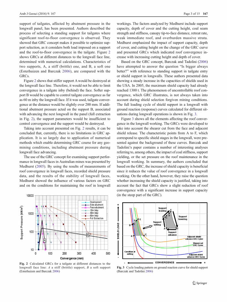
Based on the GRC concept, Barczak and Tadolini (2006)have attempted to answer the question BIs bigger alwaysbetter?^ with reference to standing support in tailgate entryor shield support in longwalls. These authors presented datashowing a steady increase in the capacities of shields used inthe USA. In 2005, the maximum shield capacity had alreadyreached 1300 t. The phenomenon of uncontrollable roof con-vergence, which GRC illustrates, is not always taken intoaccount during shield selection forgiven mining conditions.The full loading cycle of shield support in a longwall withground reaction (response) curves calculated for different sit-uations during longwall operations is shown in Fig. 3.
Figure 3 shows all the elements affecting the roof conver-gence in the longwall working. The GRCs were developed totake into account the shearer cut from the face and adjacentshield release. The characteristic points from A to F, whichcorrespond to specific shield stages in the longwall, were pre-sented against the background of these curves. Barczak andTadolini’s paper contains a number of interesting analysesreferring to, among others, the impact of coal stiffness, supportyielding, or the set pressure on the roof maintenance in thelongwall working. In summary, the authors concluded thatbased on the GRC, the increase of shield capacity is beneficialsince it reduces the value of roof convergence in a longwallworking. On the other hand, however, they raise the questionwhether increasing the shield capacity is justified, taking intoaccount the fact that GRCs show a slight reduction of roofconvergence with a significant increase in support capacity(in the steep part of the GRC).
Fig. 2 Calculated GRCs for a tailgate at different distances to thelongwall face line: A a stiff (brittle) support, B a soft support(Esterhuizen and Barczak 2006)
Fig. 3 Cycle loading pattern on ground reaction curve for shield support(Barczak and Tadolini 2006)
Arab J Geosci (2016) 9: 167 Page 3 of 15 167

Barczak and Tadolini indicate that in the case of using GRCfor shield design, the following elements occurring in alongwall panel ought to be taken into account: coal in thelongwall panel ahead of the shields and the gob behind theface. Shield support does not affect the parameters of thesetwo elements. The authors also described the various negativeeffects resulting from an increase in shield capacity, includingthe following: an increase in shield stiffness, an increase offorces in lemniscate links, or a higher toe base pressure. Theystated that a stiffer support will develop more loading than asofter support under the same load conditions.
The indicated benefits of using the GRC concept in theselection of shield parameters for specific mining conditionsprompted the authors of this paper to make an attempt to applythis concept to the conditions of Polish underground hard coalmines. To accomplish this purpose, the results of undergroundtests of shield support carried out in two longwall retreatpanels with roof caving are used. The underground studieswere performed under the Geomechanics and Control ofSoft Mine Floors and Sides (GEOSOFT) project undertakenbetween 2010 and 2013. The project was co-financed by theResearch Fund for Coal and Steel (RFCR-CT-2010-00001)and Ministry of Science and Higher Education. The objectiveof this project was to determine the influence of the floor-bearing capacity on shield performance and roof maintenancein longwall faces. In one specially prepared shield, calledBmeasuring shield^ in this paper, changes of the leg pressureswere collected. In addition, the changes of inclination of theselected shield elements were measured using inclinometers.The courses of the GRCs were calculated for two longwallfaces by means of numerical modeling. Numerical computa-tions were performed using Phase2 software, using theCoulomb–Mohr stress criterion.
Underground measurements of selected shieldparameters in two longwall panels with roof caving
To assess the shield performance in two retreat longwalls withroof caving, measurements of the pressure in legs and changesin the inclinations of selected shield elements were carried out.Longwall panels (faces), in this paper named as BA^ and BB,^were located in the same seam at a similar depth of cover, at400 and 420 m, respectively. In order to measure the shieldpressure, sensors and inclinometers were installed. The ar-rangement of the inclinometers enabled the determination ofchanges in shield geometry, including changes in shieldheight. Measurements were performed in a continuous man-ner using special apparatus built on the basis of elements anautomation system Betacontrol and Mincos (www.becker-mining.com.pl). The ground and mining conditions in thelongwall panels A and B, the measurement system used, andselected examples of the results are presented in
BCharacteristics of geological and mining conditions inlongwall panels A and B,^ BCharacteristics of the measuringshield and the method of underground measurements,^ andBResults of underground measurements of the legs’ pressureand changes in shield heights in longwalls A and B^ sections.
Characteristics of geological and mining conditionsin longwall panels A and B
Longwall panel A
Longwall panel A was the first in the mining block and wastherefore surrounded by solid (unmined) coal on both sides.The longwall panel width and length were 200 and 840 m,respectively. The cutting height varied from 2.2 to 3.2 m. Thelongwall face was retreated with natural roof caving into thegob. The depth of cover was approximately 400 m, and theseam inclination was between 5° and 9°. The immediate roofof the seam consists of the following layers: shale, sandstone,shale, coal, shale, and sandstone, respectively (Fig. 4).
The values of uniaxial compression strength (UCS) of rocklayers were relatively low and generally did not exceed10 MPa. In the immediate seam floor, there was shale andsandy shale with an underlying layer of sandstone, as shownin Fig. 4a. In longwall face A, to support the roof, two-legshields (2×244-t capacity) were used.
The basic parameters of the two-leg shields used inlongwall working A are as follows:
• Construction height range 1.7–3.3 m
• Operational height range 1.9–3.2 m
• Width 1.5 m
• Leg diameter (ø) 0.275 m
• Leg load at setting 148.0 t
• Leg load at yield 244.0 t
• Leg set/yield ratio 0.606
• Shield setting load density (SLD) 56.5 t/m2
• Shield yield load density (YLD) 93.2 t/m2
• Shield setting pressure 250.0 bar
Longwall panel B
Longwall panel B was the third in the mining block; it wassurrounded by a gob on one side (adjacent longwall panel hasbeen mined) and by solid coal on the second side (Fig. 4b).The longwall panel width and length were 230 and 885 m,respectively. The cutting height was approximately 2.9 m. Thelongwall face was retreated with natural roof caving into thegob. The depth of cover was about 420 m, and the seaminclination was between 4° and 9°.
167 Page 4 of 15 Arab J Geosci (2016) 9: 167

Longwall panel B roof seam consisted of shale withoverlying sandstone and an above layer of sandy shale,sandstone, and shale. The values of uniaxial compres-sion strength (UCS) of the rock layers were low as inlongwall panel A and did not exceed 12 MPa. In theimmediate seam floor, there was shale with underlyinglayers of varigrained sandstone, as shown in Fig. 4b.For roof maintenance in the working in longwall panelB, two-leg shields (2 × 346-t capacity) were employed.
Fundamental parameters of the two-leg shield used inlongwall working B are as follows:
• Construction height range 1.8–3.0 m
• Operational height range 2.0–2.9 m
• Width 1.5 m
• Leg diameter (ø) 0.32 m
• Leg load at setting 201.1 t
• Leg load at yield 345.8 t
• Leg set/yield ratio 0.581
• Shield setting load density (SLD) 68.6 t/m2
• Shield yield load density (YLD) 118.4 t/m2
• Shield setting pressure 250.0 bar
In both longwalls, a bi-directional (bi-di) cutting methodwas employed. In longwall workings, there is a shearer cut inone direction with a full web depth in the outbound trip andtravelling empty in the return trip. Shields employed inlongwalls A and B were controlled manually by operators.
Average daily retreat rates in longwall faces A and B were5 and 6 m/day, respectively. In the area of longwalls A and B,no seismic events occurred.
Characteristics of the measuring shield and the methodof underground measurements
In this paper, the results obtained from a GEOSOFT project(GEOSOFT 2010–2013) are used. The measuring shieldequipped with pressure sensors and inclinometers (Płonka2013) was placed against longwall panels A and B (Fig. 4).The basic parameters of the measuring shield were as follows:
• Construction height range 1.6–3.4 m
• Operational height range 2.0–3.2 m
• Width 1.5 m
• Leg diameter (ø) 0.3 m
• Leg load at setting 176.7 t
• Leg load at yield 240.3 t
• Leg set/yield ratio 0.581
• Shield setting load density (SLD) 68.5 t/m2
• Shield yield load density (YLD) 93.1 t/m2
• Shield setting pressure 250.0 bar
The measuring shield worked in longwall A as shield no.119 (about 22 m from the longwall entry, from the tail gateside) and in longwall B as shield no. 20 (about 31 m from thelongwall entry, from the tail gate side).
In longwall panel A, measurements were performed over aperiod of 4 months (the panel was retreated by approx.340 m), while in longwall panel B, the duration of the mea-surements was 11 months (the panel was retreated by approx.885 m). The values of the shield setting load density [t/m2]and shield yield load density [t/m2], presented for the basicshields used for longwalls A and B (BCharacteristics of geo-logical and mining conditions in longwall panels A and B^section of the paper) and for the measuring shield, have beencalculated taking into account the values of the leg loads atsetting or yielding, divided by the roof area supported by theshield canopy.
In longwalls A and B, the pressure measurement in the legsand changes of inclinations in the measuring shield were per-formed every second. Inclinations of the shield elements weremeasured using five inclinometers mounted on the following:base, canopy, front lemniscate link, caving shield, and one ofthe hydraulic props, as shown in Fig. 5.
Fig. 4 Profiles of roof and floor layers in the vicinity of the extracted coalseams: a longwall BA^ and b longwall BB^
Arab J Geosci (2016) 9: 167 Page 5 of 15 167

Results of underground measurements of the legs’pressure and changes in shield heights in longwalls Aand B
Based on a large number of leg pressure data collected andresults obtained from inclinometers, the load exerted on sup-port and changes in shield height for a single shield load cyclein longwalls A and B were determined. Points A to F whichcharacterize the cycle loading pattern (Fig. 3) were similar tothose adopted in Barczak and Tadolini (2005):
& A–B—shield setting; pressure in legs increase.& B–E—support loading, including points D; pressure in-
crease in legs due to shearer cut as well as C and E—increase of pressure in legs due to the release of adjacentshields.
& E–F—shield lowering. From point F, there is a shield ad-vance in the longwall face to its initial position (point A).
Figures 6, 7, and 8 are plots of the measured data showingthe changes in shield load and height in longwall faces A and
B. Changes in load were obtained from analyses and calcula-tions of the pressure recorded in the shield legs and convertedto 1 m2 of the canopy area.
When analyzing the selected examples of a full load cycleof the measuring shield in longwall faces A and B, as demon-strated in Figs. 6 and 8, it can be noted that in face A, the loadcycle of a shield lasted twice as long and was approximately230 min compared to 100 min in face B. In both faces, themeasuring shield and other shields employed in these work-ings were set against the roof manually by operators. Theresults obtained indicate that in both faces, the required(designed) shield setting load density (SLD) 68.5 t/m2 wasnot reached. In longwall face A, when the shield was beingset against the roof (point B), the SLD was about 15 t/m2. Inlongwall face B, the SLD slightly exceeded 40 t/m2. From themoment of shield setting (point B), the canopy touches theroof and shield load increase is visible. At point C, an increasein the shield load is due to the reset and advance of the adja-cent shields. Then, the longest and relatively stable shield loadcycle took place in the faces from points C to D. This is aperiod of stable shield–roof strata interaction at a moderate
Fig. 5 Distribution ofinclinometers at the measuringshield: a canopy, b caving shield,c front lemniscate link, dhydraulic leg, and e base (Pruseket al. 2013)
167 Page 6 of 15 Arab J Geosci (2016) 9: 167

roof convergence. At point D, shield load increases after theshearer face cut is visible. Point E indicates an increase in loaddue to the lowering of the immediately adjacent shield afterthe shearer cut.
In the following parts of this paper, points B and E will bereferred to as initial SLD and final load density, respectively.The characteristics of shield load variations, illustrated inFigs. 6 and 8, correspond to the steady type of pressure chang-es, in accordance with the types of pressure changes in theshield supporting cycle defined by Peng (Peng 2006). The
characteristic feature of the steady type is the occurrence, inthe long term, of an almost flat section in the course of theshield legs’ pressure changes from the shield setting to theimpact of the approaching shearer (slightly above point C topoint D). During this period, the shield has already touchedthe roof and the pressure in the legs (shield load) increases dueto roof convergence.
Figures 6 and 8 also show that in the shield supporting(load) cycles analyzed, in both longwall faces A and B, yield-ing events in the shield legs did not occur. This indicates that
Fig. 6 An example of changes inshield load and height frommeasurements in longwall BA^during a single load cycle (fromshield advance to shield lowering)
Fig. 7 An example of load andheight changes frommeasurements on shield inlongwall face BA^ during shieldadvance (F–A) and setting (A–B)
Arab J Geosci (2016) 9: 167 Page 7 of 15 167
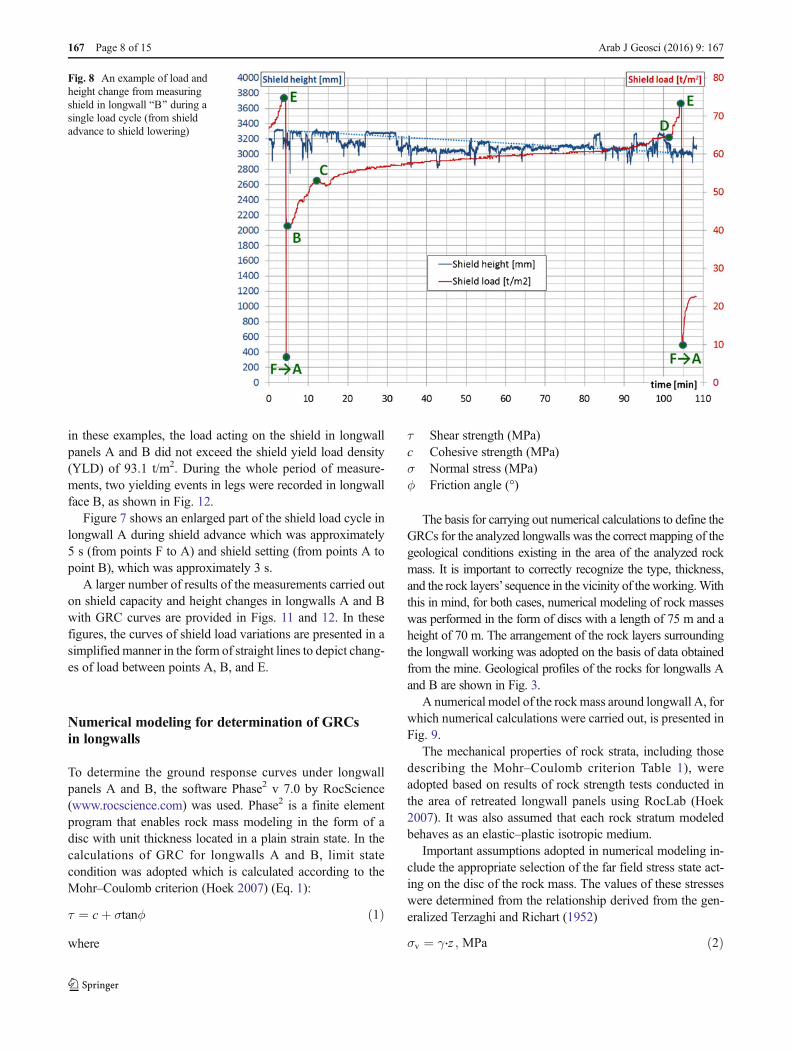
in these examples, the load acting on the shield in longwallpanels A and B did not exceed the shield yield load density(YLD) of 93.1 t/m2. During the whole period of measure-ments, two yielding events in legs were recorded in longwallface B, as shown in Fig. 12.
Figure 7 shows an enlarged part of the shield load cycle inlongwall A during shield advance which was approximately5 s (from points F to A) and shield setting (from points A topoint B), which was approximately 3 s.
A larger number of results of the measurements carried outon shield capacity and height changes in longwalls A and Bwith GRC curves are provided in Figs. 11 and 12. In thesefigures, the curves of shield load variations are presented in asimplified manner in the form of straight lines to depict chang-es of load between points A, B, and E.
Numerical modeling for determination of GRCsin longwalls
To determine the ground response curves under longwallpanels A and B, the software Phase2 v 7.0 by RocScience(www.rocscience.com) was used. Phase2 is a finite elementprogram that enables rock mass modeling in the form of adisc with unit thickness located in a plain strain state. In thecalculations of GRC for longwalls A and B, limit statecondition was adopted which is calculated according to theMohr–Coulomb criterion (Hoek 2007) (Eq. 1):
τ ¼ cþ σtanϕ ð1Þ
where
τ Shear strength (MPa)c Cohesive strength (MPa)σ Normal stress (MPa)ϕ Friction angle (°)
The basis for carrying out numerical calculations to define theGRCs for the analyzed longwalls was the correct mapping of thegeological conditions existing in the area of the analyzed rockmass. It is important to correctly recognize the type, thickness,and the rock layers’ sequence in the vicinity of the working.Withthis in mind, for both cases, numerical modeling of rock masseswas performed in the form of discs with a length of 75 m and aheight of 70 m. The arrangement of the rock layers surroundingthe longwall working was adopted on the basis of data obtainedfrom the mine. Geological profiles of the rocks for longwalls Aand B are shown in Fig. 3.
A numerical model of the rockmass around longwall A, forwhich numerical calculations were carried out, is presented inFig. 9.
The mechanical properties of rock strata, including thosedescribing the Mohr–Coulomb criterion Table 1), wereadopted based on results of rock strength tests conducted inthe area of retreated longwall panels using RocLab (Hoek2007). It was also assumed that each rock stratum modeledbehaves as an elastic–plastic isotropic medium.
Important assumptions adopted in numerical modeling in-clude the appropriate selection of the far field stress state act-ing on the disc of the rock mass. The values of these stresseswere determined from the relationship derived from the gen-eralized Terzaghi and Richart (1952)
σv ¼ γ⋅z ; MPa ð2Þ
Fig. 8 An example of load andheight change from measuringshield in longwall BB^ during asingle load cycle (from shieldadvance to shield lowering)
167 Page 8 of 15 Arab J Geosci (2016) 9: 167

σh ¼ pzm−1
; MPa ð3Þ
where
σv Vertical stressσh Horizontal stressγ Unit weight of rock (MN/m3)z Depth below surface (m)m Poisson’s ratio in reverse m= (1/υ).
Underground testing carried out in different parts of theworld shows that in many cases, the values of horizontalstresses are greater than the values determined by the Eq. (3)(Brown and Hoek 1978). The results of these studies indicate
that the ratio of horizontal to vertical stress, expressed as thecoefficient k=σh/σv, largely depends on the depth. The valueof the coefficient k ranges from 0.4 to 3.5 (depends on thedepth of cover). In the experiments of rock mass numericalmodeling in the conditions of Polish mines, the coefficientvalue k=1 is most commonly accepted for calculations andimplies a hydrostatic stress state. Accordingly, it is assumedthat for longwall panel A, the values of the vertical and hori-zontal stresses are equal and amount to σv=σh =10.0 MPa,while for longwall panel B, σv=σh =10.5 MPa.
Another important factor affecting the results of rock massmodeling in the longwall panels is properly selecting the cav-ing area parameters such as the following: angle of the cavingedge, the range of the caving zone, and the gob parameters.
Fig. 9 Numerical model of therock mass around longwall A: (a)longwall BA^ and (b) goaf oflongwall BA^
Table 1 Fundamental parameters of rock layers used in the numerical modeling
Model Types of rocks Young’smodulus(MPa)
Poisson’sratio υ
Tensilestrength(MPa)
Cohesion(MPa)
Frictionangle (°)
Dilatation(°)
Longwall panel BA^ Coal 1300 0.30 −0.014 0.31 23 2
Clay shale 2118 0.23 −0.011 0.45 28 4
Sandy shale 2822 0.23 −0.010 0.25 30 4
Sandstone 4187 0.20 −0.021 0.52 32 5
Longwall panel BB^ Coal 1100 0.30 −0.013 0.30 23 2
Clay shale 2110 0.23 −0.010 0.44 28 4
Sandstone 4085 0.20 −0.023 0.53 32 5
Arab J Geosci (2016) 9: 167 Page 9 of 15 167

When considering the caving angle, there are many differentpublications indicating its various values (Das 2000; Hosseiniet al. 2013). A wide range of research performed in Indianunderground coal mines shows that the value of this angledepends on the type of rock and its strength. In a very weaksandstone roof, the caving angle is around 75°–90°, whereasin a moderately stronger, massive sandstone roof, the cavingangle varied from 27° to 35°.
Many years of Polish mining experience in the field of coalseam methane drainage were utilized in the calculations forlongwall panels A and B. For the purposes of the proper de-sign of methane drainage holes, it was found that the cavingangle is usually about 60° in Polish conditions (Krause andŁukowicz 2013).
The height of the caving zone was calculated by means ofthe formula (Bai et al. 1995):
Hc ¼ 100⋅Ma⋅M þ b
þ c ð4Þ
where
Hc Maximum height of strata caving (m)M Extracted seam thickness (m)a, b Coefficients depending on rock dilation and lithologyc Mean square deviation
In the case of longwall panels A and B under analysis, thecalculated height of the caving zone according to Eq. (2) was7.0 m. Mechanical parameters of the caving gobs wereadopted in accordance with the conditions in longwalls Aand B according to Tajduś and Cała (1999) as follows:Young’s modulus E=700 MPa, Poisson’s ratio υ=0.4, tensilestrength = 0.08 MPa, cohesion = 0.08 MPa, friction an-gle=15°, and dilatation=0°.
In addition, the following assumptions were adopted in thenumerical models:
– Displacement on the horizontal edges of the model disk inthe vertical and horizontal direction is equal to zero.
– Displacement on the vertical edges of the model disk inthe horizontal direction is equal to zero, and in the verticaldirection, they have been released.
– For each longwall panel, the rock mass model and, then,the calculations were carried out twice: the first before theshear cut and the second after the shearer cut (after miningthe body of coal).
The results of the calculations of the rock mass responsecurves for longwall panels A and B from the numerical model-ing are presented in Fig. 10. In both cases, the obtained curvesshow the situation before and after the shearer cut. It shouldalso be noted that these curves were calculated for maximumroof convergence in the longwall workings at a distance of
4.0 m from the coal faces (in situations before shearer cut)and at a distance 4.8 m (in situation after shearer cut).
When analyzing the obtained GRCs for longwall faces Aand B, they are characterized by an elastic phase of rock massdeformation in the initial steep part of the GRCs. In thesesections of the GRCs, the support load is between 1000 and450 t/m2. The impact of the shield capacity on roof conver-gence is minimal. Then, a drop of the GRCs is observed as aresult of rock mass transition from elastic to plastic state. Roofconvergence occurs at shield support capacity under, approx-imately, 400 t/m2. In Fig. 10, the designed shield setting loaddensity (SLD), 68.5 t/m2, and shield yield load density (YLD),93.1 t/m2, were shown.
Comparison of the result of underground testsand the GRC courses for longwall panels A and B
Underground measurements, carried out for 4 months inlongwall A and for 11 months in longwall B, made availablelarge amounts of data including shield leg pressure changesand changes of inclination of its basic components. This datawas processed in order to assess shield load and changes ofshield height in two longwalls during shield advance, setting,loading, and lowering. The results are shown in Figs. 6, 7, and8. Three points were selected out of the full shield load chang-es shown in Figs. 6 and 8, namely the following: point A—thebeginning of shield setting, point B—the initial SLD, andpoint E—the final load density, before shield lowering.Figures 11 and 12 present ten simplified shield load charac-teristics of the measuring shield for the two longwalls(longwall A and B) with characteristics of GRCs. For plottingthe graphs, it was assumed that shield load changes will beconnected in their end points E, with GRC characteristics afterthe shearer cut. Furthermore, it was assumed that the change inshield height determined on the basis of inclinometer indica-tions is equal to the value of the roof convergence in thelongwall faces.
It is possible to observe different characteristics of thelongwall faces when analyzing the shield load changes, asillustrated in Fig. 10. Among these characteristics are all threemajor types of pressure changes that can occur within a min-ing cycle, namely the following: increasing, steady, and de-creasing types, as defined by Peng (2006). In the case oflongwall A, increasing pressure changes are dominant asshown in characteristic nos. 1–9. Characteristic number 10represents steady pressure changes. Figure 11 shows that inlongwall face A, initial roof convergence ranged from 115mm(characteristic no. 1) to 235 mm (characteristic no. 10), where-as final roof convergence varied from 152 mm (characteristicno. 2) to 317 mm (characteristic no. 10). The values of initialSLD were between 13.52 and 61 t/m2, while the final loaddensity ranged from 22 to 82 t/m2. In the case of longwall face
167 Page 10 of 15 Arab J Geosci (2016) 9: 167

B (Fig. 12), initial roof convergence varied from 40mm (char-acteristic no. 1) to 380 mm (characteristic no. 10) whilst thefinal roof convergence ranging from 327 mm (characteristicno. 4) to 480 mm (characteristic no. 10). The initial SLDranged from 30 to 54 t/m2, whereas final load density oscil-lated between 47 and 97 t/m2. In longwall face B, there weretwo cases where the value of the shield load (pressure in legs)slightly exceeded YLD (characteristic nos. 3 and 4), resultingin the yield valve opening. In the case of longwall face B, thecharacteristics of shield load (pressure changes in legs) ofsteady pressure changes (characteristic nos. 1, 2, 5, 6, 7, 8,9) are dominant. Changes in shield load in this longwall weresimilar to the characteristics of increasing and decreasingtypes of pressure change, designated by numbers 3, 4, and10, respectively. The probable cause of characteristic no.10’s decreasing pressure changes, occurring in longwall B,
was the local decrease of the floor-bearing capacity parame-ters (mainly by water inflow), as well as the presence of toomuch rock/coal debris between the canopy and roof strata.Due to these factors, when the shield was seated against theroof, the initial shield load reached a value of about 53 t/m2
and then started to decrease as a result of shield base penetra-tion in the floor and the crushing of rock/coal debris on thecanopy.
When analyzing the characteristics of shield load presentedin Figs. 11 and 12, it can be stated that the values of initialSLD are varied, both in longwall A and longwall B. This ismainly due to the manual setting of the measuring shield infaces A and B. In Polish hard coal mines, there are only a fewoperational longwall faces where the shields are set against theroof by means of automatic setting systems (electrohydraulicsystems). Such systems enable the avoidance of insufficient
Fig. 10 Ground reaction curvesfor longwall panels BA^ and BB^determined from numericalmodeling—situations in thelongwall before and after shearercut; 1—shield setting load density(SLD), 2—shield yield loaddensity (YLD)
Fig. 11 Ground reaction curvesfor longwall panel BA,^ beforeand after the shearer cut, withchanges of shield load and roofconvergence (characteristic nos.1–10)
Arab J Geosci (2016) 9: 167 Page 11 of 15 167

shield setting below the setting pressure in longwall faces. Ingeneral, when the shield is set below the recommended settingpressure, adverse events may occur in the longwall workingsdue to excessive roof convergence such as minor or massiveroof falls. The impact of shield capacity on maintaining theroof was described in Trueman et al. (2011), based on anexample from Australian underground hard coal mines. Inlongwall faces A and B, despite setting the shield against theroof below the recommended setting pressure, no significantproblems in maintaining the roof occurred. This most proba-bly resulted from relatively favorable ground and mining con-ditions, such as not having a high depth of cover in compar-ison with other Polish mine conditions, a lack of seismicevents, and regular roof caving behind the shield line (lackof overhanging roof strata behind the shields).
Figures 13 and 14 present the characteristics of GRCs andthe average characteristics of changes in shield load and roofconvergence in longwall faces A and B.
When analyzing the average values of roof convergenceand shield load, based on the measurements in longwall facesA and B, it can be observed that higher initial roof conver-gence took place in face B and was equal to 270 mm, incomparison to 216 mm in face A. In longwall face B, therewas also higher roof convergence before and after the shearercut which amounted to 123 mm. In longwall face A, the av-erage convergence before and after the shearer cut was con-siderably lower and was equal to 19 mm. Final roof conver-gence was 235 and 393 mm in faces A and B, respectively.Taking into account the fact that the values of convergencewere determined about 4 m from the coal faces before theshearer cut and 4.8 m after the shearer cut, the average relativevalues of convergence were as follows: for longwall face A—average initial roof convergence of 54 mm/m and averagefinal roof convergence of 49 mm/m and for longwall faceB—average initial roof convergence of 67.5 mm/m and aver-age final roof convergence of 71 mm/m. The average values
Fig. 12 Ground reaction curvesfor longwall panel BB,^ beforeand after the shearer cut, withchanges of shield load and roofconvergence (characteristic nos.1–10)
Fig. 13 Average shield load and roof convergence in longwall face BA^with GRC: 1—GRC before shearer cut; 2—GRC after shearer cut; A—beginning of shield setting, point B—initial shield load at setting, andpoint E—final shield load, before shield lowering
Fig. 14 Average shield load and roof convergence in longwall face BB^together with GRC: 1—GRC before shearer cut; 2—GRC after shearercut; A—beginning of shield setting, point B—initial shield load at setting,and point E—final shield load, before shield lowering
167 Page 12 of 15 Arab J Geosci (2016) 9: 167

of initial SLD and final load density in face A were 32 and44.8 t/m2, respectively, whereas in face B, they measured 41.9and 75.4 t/m2, respectively. These values of initial shield loadat setting indicate that the measuring shield was set inlongwalls A and B below the setting pressure (below250 bar). After calculations, it can be stated that the averagesetting pressure in face Awas 120 bar while in face B, it was150 bar. The reason for this was the fact that the shields wereset manually, as previously stated.
The factors that had significant impact on the various roofconvergences and shield loads in faces A and B are different,for instance, the slightly increased height of longwall workingB (3.2 m) and specific differences in roof and floor stratifica-tion (Fig. 4). However, the location of the longwall panels hadthe greatest influence on this condition. Longwall panel Awassurrounded by solid (unmined) coal on both sides, whilelongwall panel B was surrounded by gob on one side, whichis more unfavorable for stability in underground workings.
Certain discrepancies can be found when comparing theabsolute and relative average values of roof convergence (cal-culated for 1 m of longwall working length) in longwall faces Aand B to findings in other countries. For example, Medhurst(2005), who analyzed Australian underground hard coal mines,states that cavities start to develop in the roof strata when roofconvergence is between 30 and 50 mm. When roof conver-gence exceeds 100 mm, the overlying strata are broken. Inlongwalls A and B, roof convergence was higher with no ad-verse events observed. In these longwall faces, neither minornor major roof falls occurred nor were any serious obstacles tomining operations (e.g., face instability or stoppages, irregularface advance) encountered. Singh and Singh (2009a), on thebasis of longwall working observations and numerical model-ing carried out in India, concluded that roof convergence in alongwall working should not exceed 75 mm/m, and this shouldform a design criterion for optimal shield selection for the staticload condition. This criterion was fulfilled in the case oflongwall faces A and B, where both average initial and finalroof convergences did not exceed 75 mm/m.
Conclusions and recommendation
This paper shows the use of the GRC concept in the analysisof shield and roof strata interaction in two retreat longwallfaces with roof caving in Polish underground coal mines.The longwall panels were retreated at the heights of 2.9 and3.2 m, respectively, at a depth of cover of about 400 m, instatic load conditions. In the two longwall faces studied, theresearch was conducted using a measuring shield for periodsof 4 and 11 months. It has been shown that in cases of manualshield setting, the shield is often not set against the roof withthe appropriate amount of initial pressure. At the time of car-rying out the measurement in longwalls A and B, the
measuring shield has never reached the recommended valueof SLD (68.5 t/m2). The use of an electrohydraulic controlsystem, in which the shield is set against the roof automatical-ly, is without doubt more advantageous.
The results of the measurements of initial and final roofconvergences in the longwall faces are presented. Initial con-vergence ranged from 216 to 270 mm, whereas final conver-gence was between 235 and 393 mm in faces A and B, re-spectively. The values of roof convergence were obtainedusing measuring shield height variations. This kind of conver-gence measurements is relatively difficult to carry out formany reasons: the high variability of the situation in thelongwall working caused by shearer cutting the coal face,shield advance, and progressive roof caving. While there aremany publications on continuous pressure measurement instatic shield legs, the results of continuous measurement ofconvergence in operational longwall faces are relatively rare.
Comparing the absolute average values of roof conver-gence, it can be concluded that they do not confirm experi-ences of Australian mines, where, at the values, cavitiesstarted to develop in the roof strata or the overlying stratabroke (Medhurst 2005). For relative average values of finalroof convergence, from 49 mm/m in longwall A to 71 mm/min longwall B, the values are consistent with given determinedconvergence for the conditions in Indian mines. Singh andSingh (2010) concluded that, to maintain stability of the roofin a longwall working, convergence ought not to exceed75 mm/m. In longwalls A and B, roof convergence was lowerand there were no difficulties in maintaining the roof. Theobserved differences between experiences of Australian minesand Polish ones show that caution is advised applying empir-ical criteria for different conditions than the ones that theywere determined for.
This paper highlights that during longwall mining, theremay be various types of pressure changes in shield legs (shieldload) which can be described as increasing, steady, and de-creasing types of pressure change. This is particularly notice-able in the case of longwall B. This situation is caused by thevariation in ground and mining conditions in the longwallpanel as a consequence of the lowering of the roof or floorrock strength parameters, the presence of rock/coal debris onthe canopy, or damage to the hydraulic props.
The results of the measurements also indicate that in thecase of the first longwall panels in a mining block which aresurrounded on both sides by solid coal (longwall panel A),roof convergence and shield load density are smaller whencompared to longwall panels surrounded by gob on one side(longwall panel B). The average values of initial SLD andfinal load density were between 32 and 44.8 t/m2 in longwallA and varied from 41.9 and 75.4 t/m2 in longwall B.
Giving an unequivocal answer to the question BIs biggerbetter?^ posed by Barczak and Tadolini (2006) remains a task.On the one hand, experience gained in Moranbah North mine
Arab J Geosci (2016) 9: 167 Page 13 of 15 167

in Australia (where shields with, most probably, the largestpossible capacity of 1750 t) shows that shields of greater ca-pacity reduce the number of roof falls and the downtimes inthe production (Martin et al. 2012). On the other hand, the datapresented in Singh and Singh (2009a) on Indian coal minesindicate that an increase in shield capacity may result in anincrease in the roof convergence in a longwall working locat-ed in certain ground and mining conditions. The authors ofthis paper caution against unjustified increase of shield capac-ity without proper characterization of the ground and miningconditions in a given longwall panel. It is strongly recom-mended that a system enabling ground characterization andmining conditions appropriate for shield capacity determina-tion and selection be developed.
Open Access This article is distributed under the terms of the CreativeCommons At t r ibut ion 4 .0 In te rna t ional License (h t tp : / /creativecommons.org/licenses/by/4.0/), which permits unrestricted use,distribution, and reproduction in any medium, provided you give appro-priate credit to the original author(s) and the source, provide a link to theCreative Commons license, and indicate if changes were made.
References
Bai M, Kendorski F, Van Roosendaal D (1995) Chinese and NorthAmerican high-extraction underground coal mining strata behaviorand water protection experience and guidelines. Proceedings of 14thInternational Conference on Ground Control in Mining,Morgantown
Bai Q-S, Shi-Hao T, Zhang X-G, Zhang C, Yuan Y (2014) Numericalmodeling on brittle failure of coal wall in longwall face—a casestudy. Arab J Geosci 7(12):5067–5080
Barczak TM,Oyler DC (1991)Amodel of shield-strata interaction and itsimplications for active shield setting requirements. Report ofInvestigations 9394. United States Department of the Interior
Barczak TM, Tadolini SC (2006) Longwall shield and standing gateroadsupport designs—is bigger better? Proceedings of Longwall USA,Pittsburgh, Pennsylvania, June 5–7
Barczak TM, Esterhuizen GS, Ellenberger J, Zahng P (2008) A first stepin developing standing roof support design criteria based on groundreaction data for Pittsburgh seam longwall tailgate support. In:Proceedings of the 27th International conference on ground controlin mining, West Virginia: 347–357
Biliński A (1976) Criteria of support selection for longwall workings withnatural roof caving. Prace GIG, Seria dodatkowa, Katowice (InPolish)
Biliński A (1983) Principles of underground working maintenance inlongwalls with rockburst hazard. Archiwum Górnictwa. Tom 28.Zeszyt 2. Kraków (In Polish)
Brady B, Brown E (2006) Rock mechanics for underground mining.The Netherlands, Springer, Third edition 2004, reprinted withcorrections
Brown E, Hoek E (1978) Trends in relationship between measured in-situstresses. Int J Rock Mech Min Sci Geomech Abstr 15:21–215
Carranza-Torres C, Fairhurst C (2000) Application of the convergence-confinement method of tunnel design to rock masses that satisfy theHoek-Brown failure criterion. Tunn Undergr Space Technol 15(2):187–213
Das SK (2000) Observations and classification of roof strata behaviourover longwall coal mining panels in India. Int J Rock MechMin Sci37(4):585–597
Dubois R (1960) Die Abhängigkeit der Konvergenz im Streb vonverschiedenen Faktoren. De L’industrie Minerale, InternationalerKongress für Gebrigsdruckforschung 16–20, Paris:469–488
Esterhuizen GS, Barczak TM (2006) Development of ground responsecurves for longwall tailgate support design. Colorado, Proceedingsof the 41st U.S. Rock Mechanics Symposium:1–10
Frith R (2005) Half a career trying to understand why the roof along thelongwall face falls in from time to time? In: Proceedings of the 24thInternational conference on ground control in mining, WestVirginia: 33–43
Frith R (2013) A holistic examination of the geotechnical design oflongwall shields and associated mining risks. In: Proceedings ofthe 13th Coal Operators’ Conference:38–49
Gao F, Stead D, Coggan J (2014) Evaluation of coal longwall cavingcharacteristics using an innovative UDEC Trigon approach.Comput Geotech 55:448–460
GEOSOFT (2010–2013) Geomechanics and control of soft mine floorsand sides. Project co-financed by Research Fund for Coal & Steel.Project no. RFCR-CT-2010-00001, realization in (not published)
Herwig H (1981) Die Wirkung des Gebirgdruckes auf denHangendzustand im Streb. Glückauf No 117
Hoek E (2007) Practical rock engineering. Rocscience Inc, www.rocscience.com
Holub K, Rusajova J, Holecko J (2011) Particle velocity generated byrockburst during exploitation of the longwall and its impact on theworkings. Int J Rock Mech Min Sci 48:942–949
Hosseini N, Goshtasbi K, Oraee-Mirzamani B (2013) Calculation of pe-riodic roof weighting interval in longwall mining using finite ele-ment method. Arab J Geosci. doi:10.1007/s12517-013-0859-8
Hoyer D. (2012) Early warning of longwall of cavities using LVA soft-ware. In: 12th Coal Operators’ Conference, University ofWollongong & the Australasian Institute of Mining andMetallurgy: 69–77
Hussain MA, Ibrahim AR, Imbay SS (2013) Load calculations and se-lection of the powered supports based on rock mass classificationand other formulae for Abu-Tartur longwall phosphate mining con-ditions. Journal of Engineering Sciences, Assiut University, Facultyof Engineering, Vol. 41, No. 4, July
Jacobi O (1981) Praxis der Gebirgsbeherrschung. Verlag GlückaufGmbH, Essen
Keim SK, Miller MS (1999) Case study evaluation of geological influ-ences impacting mining conditions at a West Virginia longwallmine. Int J Coal Geol 41:51–71
Krause E, Łukowicz K (2013) Zagrożenia gazowe. Bezpieczeństwopracy w kopalniach węgla kamiennego, praca zbiorowa podredakcją Władysława Konopko. Tom 2, Zagrożenia Naturalne:9–54 (In Polish)
Langosch U, Ruppel U, Wyink U (2003) Longwall roof control by cal-culation of the shield support requirements. In: Proceedings of theCoal Operators’ Conference:162–172
Manteqi H, Shahriar K, Torabi R (2012) Prediction of first weightingdistance in longwall coal mining by 3D numerical modeling—a casestudy. In: Proceedings of the 31st International Conference onGround Control in Mining:1–9
Martin K, Kizil M, Canbulat I (2012) Analysing the effectiveness of the1750 tone shields atMoranbah NorthMine. In. 12th Coal Operators’Conference, University of Wollongong & the Australasian Instituteof Mining and Metallurgy:31–41
Medhurst TP (2005) Practical considerations in longwall support behav-iour and ground response. Coal Conference 2005 Brisbane, QLD,26–28 April
Mucho TP, Barczak TM, Dolinar DR, Bower J, Bryja JJ (1999) Designmethodology for standing secondary roof support in longwall
167 Page 14 of 15 Arab J Geosci (2016) 9: 167

tailgates. In: Proceedings of the 18th International conference onground control in mining, West Virginia: 136–148
Oreste PP (2003) Analysis of structural interaction in tunnels using thecovergence–confinement approach. Tunn Undergr Space Technol18:347–363
Özel R, Ünal E (1998) Support and strata interaction in longwall face. IntJ Rock Mech Min Sci 35(4/5):484–485
Payne DA (2008) Crinum Mine, 15 longwalls 40 million tones 45 rooffalls—what did we learn? In: Proceedings of the 8th Coal Operators’Conference:22–43
Peng SS (1987) Support capacity and roof behaviour at longwall faceswith shield supports, International Journal ofMining and GeologicalEngineering:29–57
Peng SS (1998):What can a shield leg pressure tell us? Coal Age, March:54-57
Peng SS (2006) Longwall mining. 2nd Edition. MorgantownPłonka M (2013) Calculations of ground response curve GRC based on
measurements of operational powered roof support in the longwallpanels with natural roof caving. Research GIG No 11110333–152,(not published) (In Polish)
Płonka M, Rajwa S (2011) Assessment of powered support loadings inplow and shearer longwalls in regard to the pressure measurementsin props. In: Proceedings of the International Mining Forum 2011,LW Bogdanka, Poland, A Balkema Book:221–232
Płonka M, Prusek S, Rułka K (2003) 3D strata model application for theselection method of the support for longwall excavation. IIIInternational Conference Mining Techniques: 233–245
Prusek S (2014) The factors causing roof fall occurrences in longwallfaces with natural roof caving. Przegląd Górniczy 3:71–78 (InPolish)
Prusek S, Rajwa S, Stoiński K (2005a) Kriterien zur Abschatzung desRisikos von Strebschaden. Glückauf-Forschungshefte nr 3 3:92–95
Prusek S, Rajwa S, Walentek A (2005b) An application of numericalmodeling for the assessment of the roof stability between the coalface and the tip of canopy. In: Proceedings of the XII InternationalScientific Conference - Górnicze Zagrożenia Naturalne. Katowice:229–252 (In Polish)
Prusek S, Rajwa S, Kasperkiewicz W, Budniok T (2013) Assessment ofperformance of powered shield support used on weak floor. In:Proceedings of the World Mining Congress, Canada.
Saeedia G, Shahriara K, Rezaia B, Karpuzb C (2008) Numerical model-ing of out-of-seam dilution in longwall retreat mining. Int J RockMech Min Sci 47(4):533–543
Sastry VR, Nair R (2009) Study of behaviour of workings in longwallpanel based on field instrumentation. Int J MinMiner Eng 1(3):232–247
Shabanimashcool M, Jing L, Li CC (2014) Discontinuous modeling ifstratum cave-in in a longwall coal mine in the Arctic area. GeotechGeol Eng 32:1239–1252
Singh GSP, Singh UK (2009a) A numerical modeling approach for as-sessment of progressive caving of strata and performance of
hydraulic powered support in longwall workings. Comput Geotech36(7):1142–1156
Singh GSP, Singh UK (2009b) Assessment of dynamic loading and rapidyield valve requirement for shield supports in longwall workings.Trans Inst Min Metall Section A Min Technol 118(1):47–52
Singh GSP, Singh UK (2010) Prediction of caving behavior of strata andoptimum rating of hydraulic powered support for longwall work-ings. Int J Rock Mech Min Sci 47:1–16
Smart BGD, Redfern A (1986) The evaluation of powered support fromgeological and mining practice specifications information. In:Proceedings of the 27th U.S. Symposium on Rock Mechanics(USRMS), Tuscaloosa, Alabama, Chapter 54- Longwall FaceSupport
Szweda S (2003) Dynamic action of rock mass on the powered supportlegs. J Min Sci 39(2):154–161
Tajduś A, Cała M (1999) Określenia parametrów obudowy wyrobiskkorytarzowych w oparciu o obliczenia numeryczne. Kraków,AGH, Geotechnika w górnictwie i budownictwie specjalnym:253–265 (In Polish)
Terzaghi K, Richart FE (1952) Stresses in rock about cavities.Geotechnique 3:57–90
Trueman R, Lyman G, Cocker A (2009) Longwall roof control through afundamental understanding of shield-strata interaction. Int J RockMech Min Sci 46:371–380
Trueman R, Callan M, Thomas R, Hoyer D (2010) Quantifying the im-pact of cover depth and panel width on longwall shield-strata inter-actions. In: Proceedings of the 10th Coal Operators’ Conference:97–107
Trueman R, Thomas R, Hoyer D (2011) Understanding the causes of roofcontrol problems on a longwall face from shield monitoring data—acase study. In. 11th Underground Coal Operators’ Conference,University of Wollongong & the Australasian Institute of Miningand Metallurgy:40–47.
Wiklund B, Kizil MS, Canbulat I (2011) Development of a cavity pre-diction model for longwall mining, 11th Underground CoalOperators’ Conference, University of Wollongong & theAustralasian Institute of Mining and Metallurgy:48–59
Wilson AH (1975) Support load requirements on longwall faces. MinEng 134:479–491
Winstanley A (1951) Die Beherrschung des Hangenden immechanisierten Abbau. International Conference about rockpressure and support in the workings, 24–28 April, Liege:203–213
Yasitli NE, Unver B (2005) 3D numerical modeling of longwall miningwith top-coal caving. Int J Rock Mech Min Sci 42:219–235
Yavuz H (2004) An estimation method for cover pressure re-establishment distance and pressure distribution in the goaf oflongwall coal mines. Int J Rock Mech Min Sci 41:193–205,http://www.becker-mining.com.pl
Arab J Geosci (2016) 9: 167 Page 15 of 15 167