Embed Size (px)
Citation preview
Applying Systems Engineering in Mine Automation
Jarmo PuputtiSANDVIK TAMROCK
System EngineeringLoaders & Drills
Content
1. Introduction- Sandvik Tamrock- Underground Mining- AutoMine Ore Transportation System
2. Sandvik Tamrock Offering Development Process
3. AutoMine System Delivery Process
4. Summary
1. Introduction
Sandvik
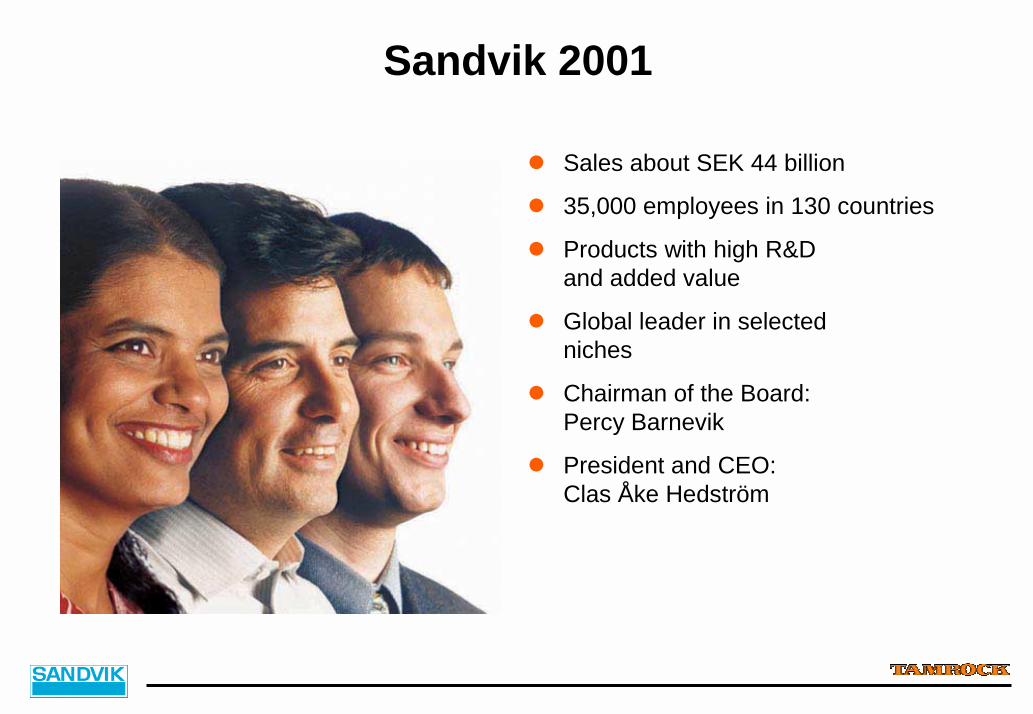
Sandvik 2001
! Sales about SEK 44 billion
! 35,000 employees in 130 countries
! Products with high R&D and added value
! Global leader in selected niches
! Chairman of the Board: Percy Barnevik
! President and CEO:Clas Åke Hedström

Sandvik AB
Board of Directors
Group Executive Management
Group Staffs
Business Areas
Sandvik Tooling
Sandvik Coromant
Sandvik CTT
Sandvik Hard Materials
Sandvik Tamrock
VA- Eimco
Driltech Mission
Sandvik Materials Handling
Sandvik Mining and Construction Sandvik Specialty Steels
Sandvik Steel
Kanthal
Sandvik Process Systems
Sandvik International
Sandvik South East Asia
Sandvik Information Systems
Sandvik Service
Other Group Companies
Associated Companies
Separate Business Units Regional Companies Service Companies
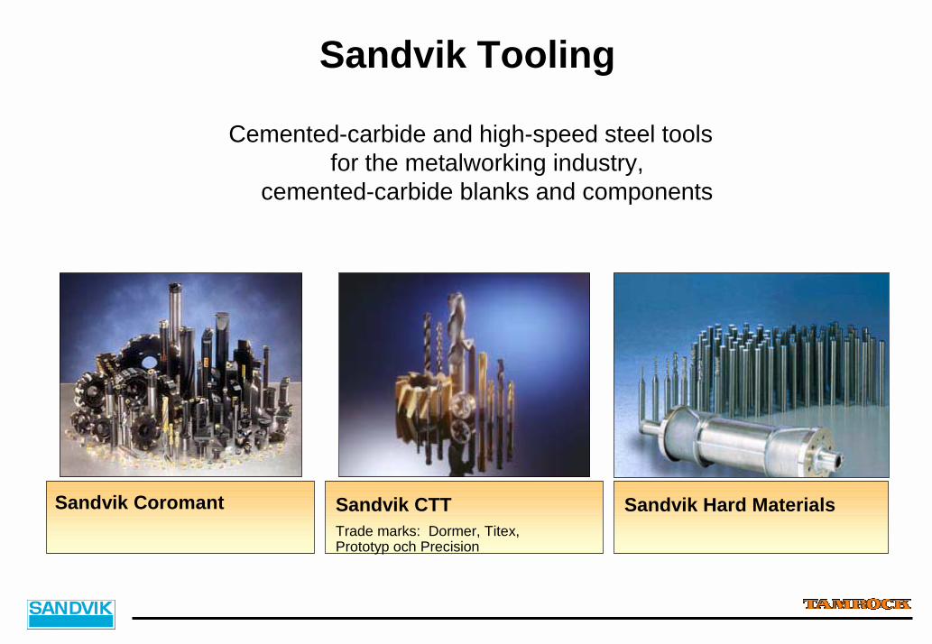
Sandvik Tooling
Cemented-carbide and high-speed steel toolsfor the metalworking industry,
cemented-carbide blanks and components
Sandvik Coromant Sandvik CTTTrade marks: Dormer, Titex,Prototyp och Precision
Sandvik Hard Materials
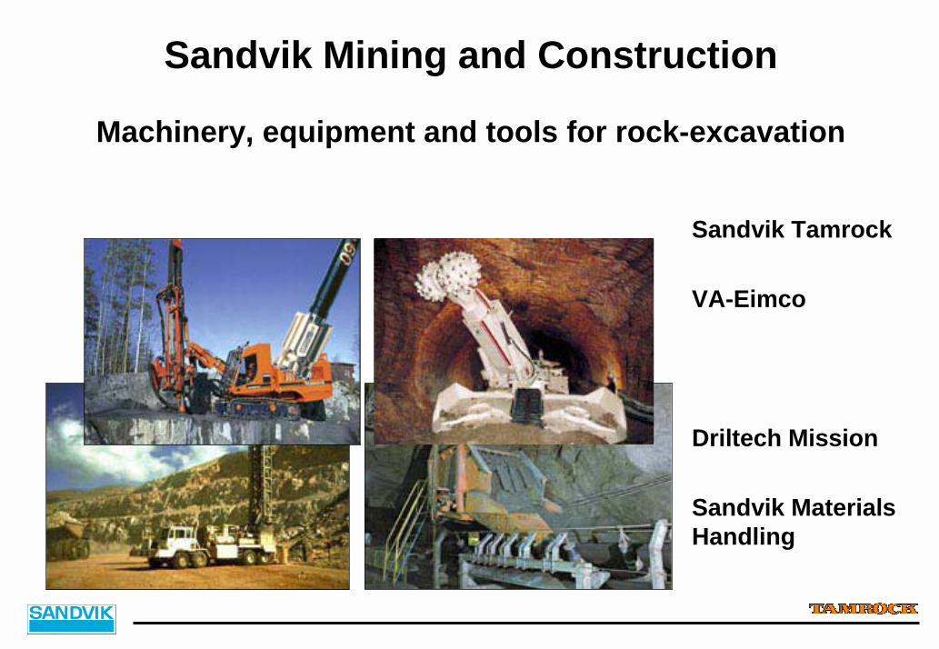
Sandvik Mining and Construction
Machinery, equipment and tools for rock-excavation
Sandvik Tamrock
VA-Eimco
Driltech Mission
Sandvik MaterialsHandling
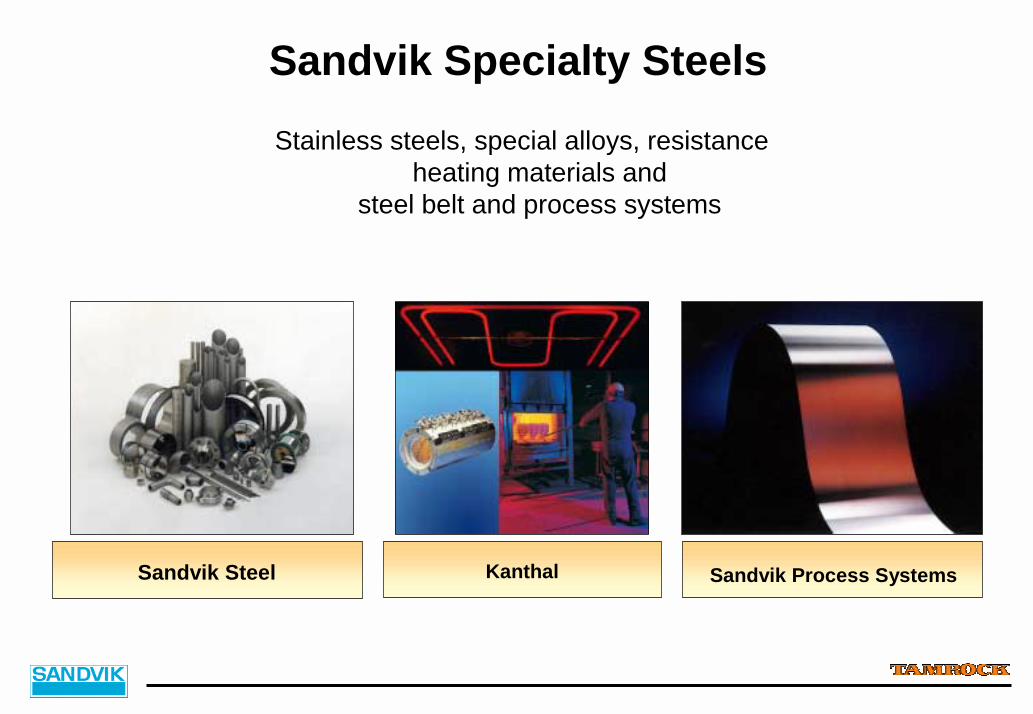
Sandvik Specialty SteelsStainless steels, special alloys, resistance
heating materials and steel belt and process systems
Sandvik Steel Kanthal Sandvik Process Systems
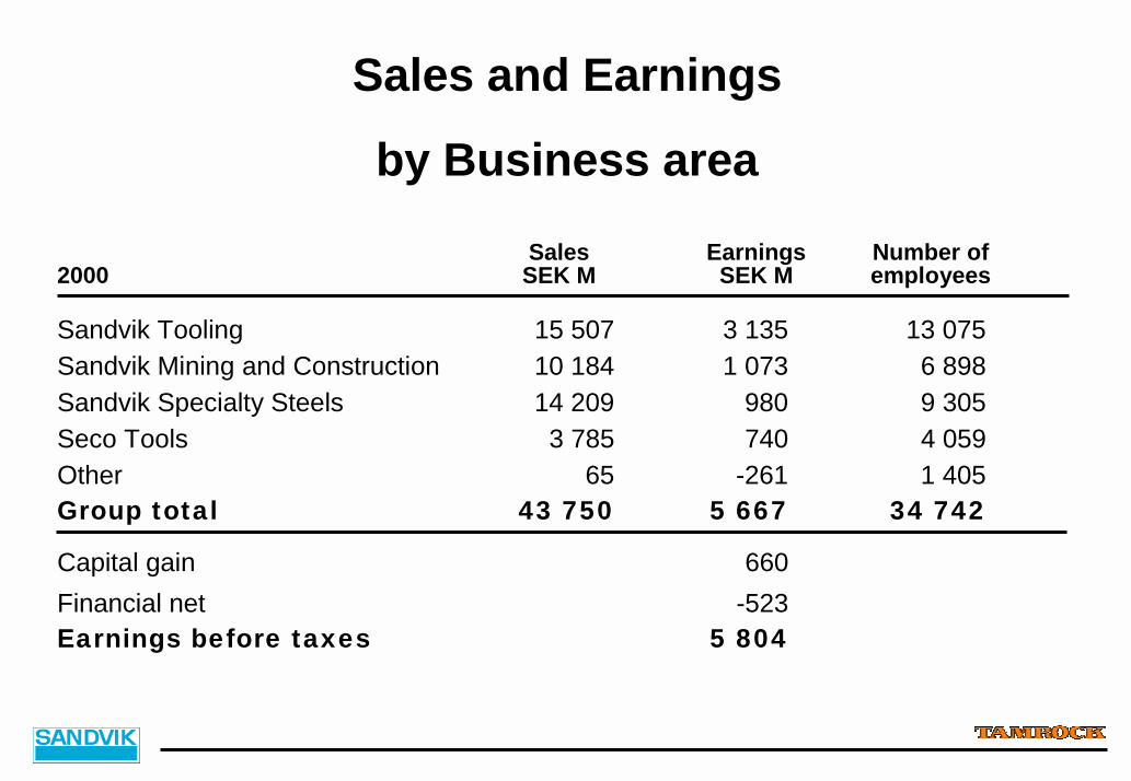
Sales and Earnings
Sales Earnings Number of2000 SEK M SEK M employees
Sandvik Tooling 15 507 3 135 13 075Sandvik Mining and Construction 10 184 1 073 6 898Sandvik Specialty Steels 14 209 980 9 305Seco Tools 3 785 740 4 059Other 65 -261 1 405Group total 43 750 5 667 34 742
Capital gain 660Financial net -523Earnings before taxes 5 804
by Business area

Sales and Earnings 1981-2000
Operating profit, *incl. Capital gain
0
10 000
20 000
30 000
40 000
50 000
81 82 83 84 85 86 87 88 89 90 91 92 93 94 95 96 97 98 99 000
2 000
4 000
6 000
8 000
10 000
Sales, SEK M Earnings, SEK M
*
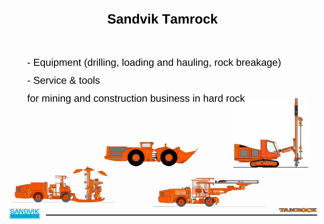
Sandvik Tamrock
- Equipment (drilling, loading and hauling, rock breakage)
- Service & tools
for mining and construction business in hard rock
1. Introduction
Underground Mining

Typical Massive Underground Block Cave Mine
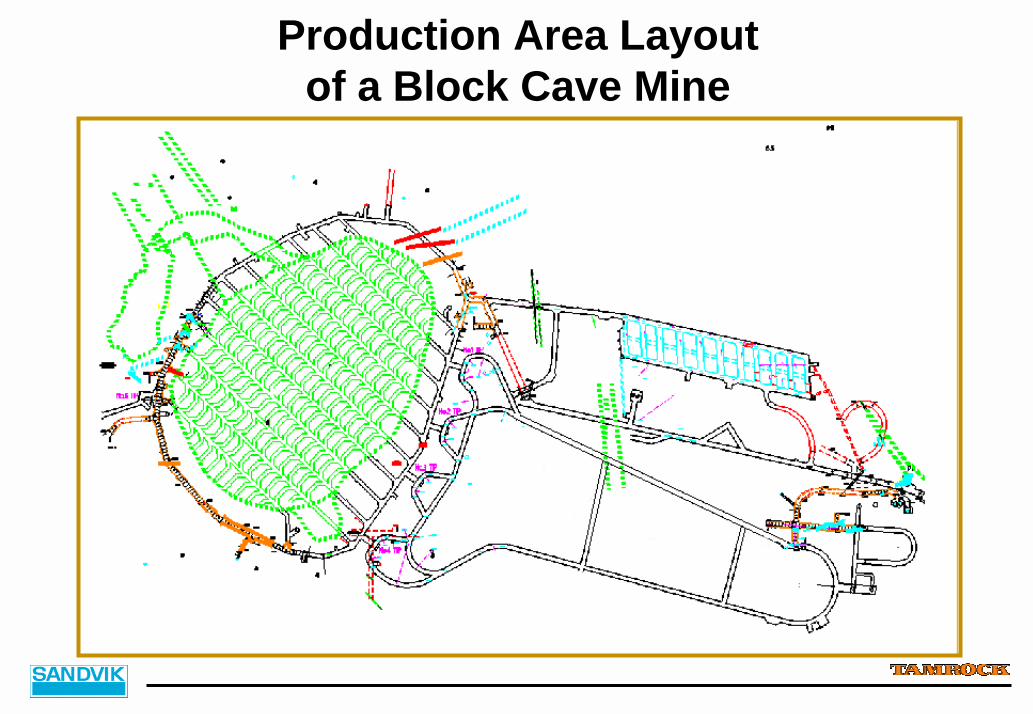
Production Area Layoutof a Block Cave Mine
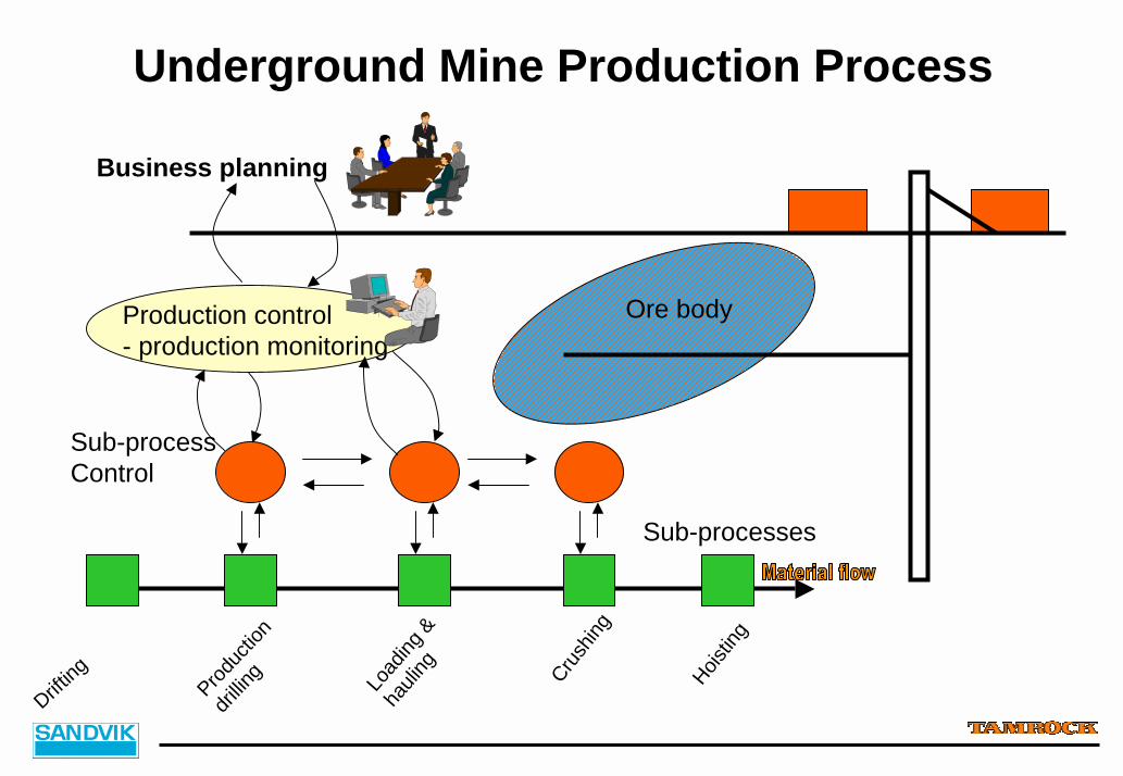
Underground Mine Production Process
Ore bodyProduction control- production monitoring
Sub-processes
Business planning
Drifting Prod
uctio
n
drillin
g Load
ing &
hauli
ng Crush
ing
Hoistin
g
Sub-processControl
1. Introduction
AutoMine Ore Transportation System

FEATURESFEATURESFEATURESFEATURES!System for automated ore
transportation!Operator can supervise &
monitor multiple machines from a control room
!Automated tramming & dumping
! Teleoperated LHD bucket loading
!Automated truck box loading
! Traffic control! Fleet & production area
supervision!Condition & production
monitoring & reporting!Remote diagnostics!Connectivity to external
onsite systems
Ore Transportation System
BENEFITSBENEFITSBENEFITSBENEFITS! Increased safety! Improved working
conditions!Higher fleet utilization """"
increased production capacity
!Optimized tramming speeds """" smooth equipment operation
!Reduced maintenance & lower operating costs
!Real time production supervision & control
! Integration with onsite systems """" improved control of mining process
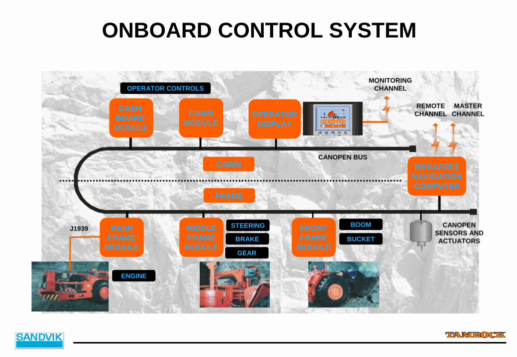
DASH-BOARD MODULE
CHAIRMODULE
OPERATORDISPLAY
REARFRAME
MODULE
MIDDLEFRAME
MODULE
FRONTFRAME
MODULE
INFRAFREENAVIGATIONCOMPUTER
CABIN
FRAME
ONBOARD CONTROL SYSTEM
MASTERCHANNEL
REMOTECHANNEL
MONITORINGCHANNEL
ENGINE
STEERING
BRAKE
GEAR
BOOM
BUCKET
OPERATOR CONTROLS
CANOPEN BUS
J1939 CANOPEN SENSORS AND ACTUATORS

INFRAFREE® NAVIGATION PRINCIPLEPOSITION MEASUREMENT BASED ONDEAD RECKONING:• DIRECTION FROM GYRO & ARTICULATION ANGLE• DISTANCE FROM DRIVE LINE• ALWAYS SOME DRIFT IN DEAD RECKONING, DUE TO
GYRO & WHEEL SLIP• DRIFT IN DEAD RECKONING IS CORRECTED
UTILIZING THE ENVIRONMENT MODEL AND WALL PROFILES
INFRAFREE® NAVIGATION SYSTEM

InfraFREE® Navigation
POSITIONSPEEDHEADING
GUIDANCE CONTROLLER
ONBOARD CONTROLSYSTEM
SPEED & STEERING
POSITION ESTIMATORWALLPROFILECORRELATION
SCANNINGLASER,
ENVIRONMENTMEASUREMENT
PRE-TAUGHTPATH &
SEGMENTS
PRE-TAUGHTENVIRONMENT
MODEL
DEAD RECKONING(LOCAL POSITION)
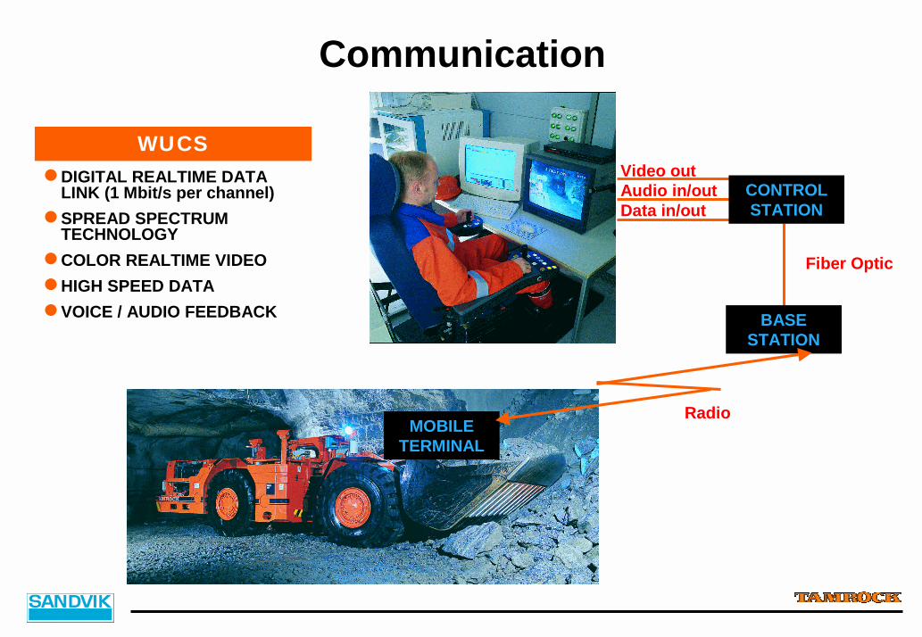
Communication
Video outAudio in/outData in/out
!DIGITAL REALTIME DATA LINK (1 Mbit/s per channel)
!SPREAD SPECTRUM TECHNOLOGY
!COLOR REALTIME VIDEO!HIGH SPEED DATA!VOICE / AUDIO FEEDBACK
WUCS
CONTROL STATION
BASE STATION
MOBILE TERMINAL
Fiber Optic
Radio

SAFETYSYSTEMSAFETYSYSTEM
ProductionProduction AreaAreaPLCPLCPLCPLC
PLCPLC
Safety PLC’sSafety PLC’s
MISSION CONTROL SYSTEM
MISSION CONTROL SYSTEM
CentralCentralCC
ontrolontrolRoomRoom
Mine planningMine planningExternalExternalsystemssystemsMaintenanceMaintenance
OPERATOR STATIONS
OPERATOR STATIONS
SCADASCADA
Wireless Communication
Wireless Communication OnboardOnboard
SystemsSystems
AUTOMINE SYSTEM OVERVIEW
NAVIGATIONNAVIGATION MONITORINGMONITORINGCAMERASCAMERAS
VIDEO
Ore Transportation System
2. Sandvik Tamrock Offering Development Process
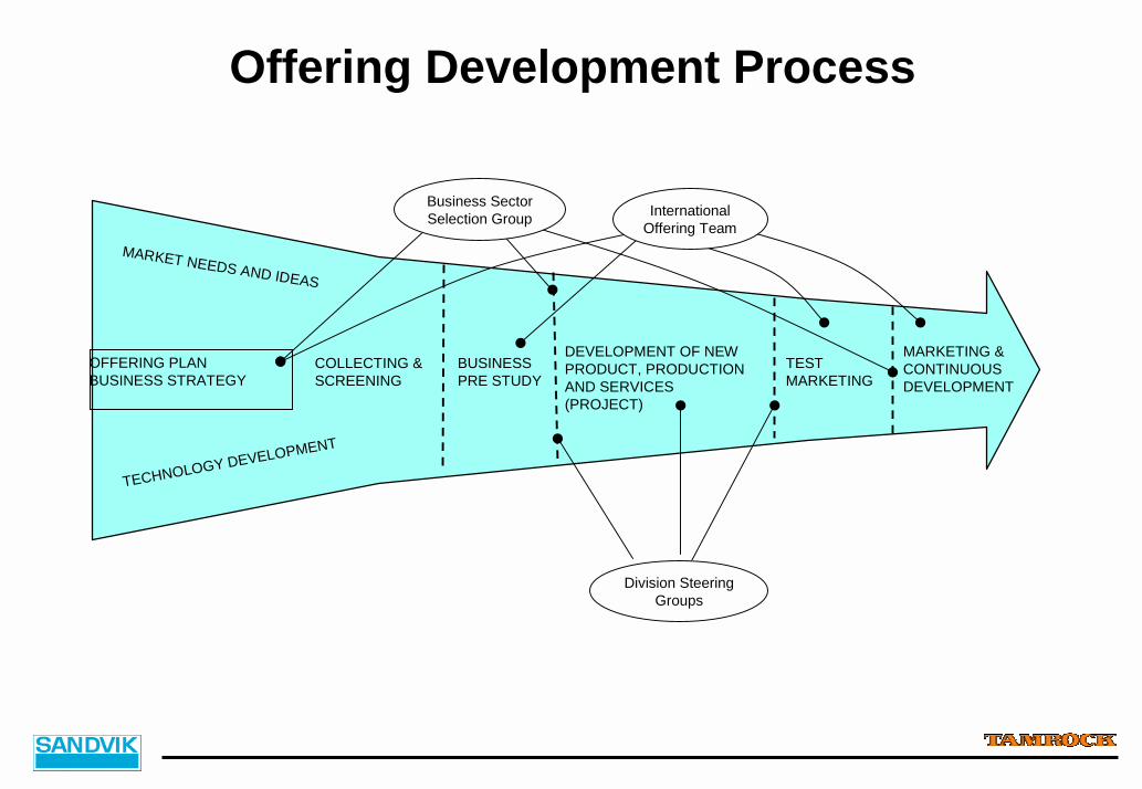
Offering Development Process
OFFERING PLANBUSINESS STRATEGY
COLLECTING &SCREENING
BUSINESSPRE STUDY
DEVELOPMENT OF NEWPRODUCT, PRODUCTIONAND SERVICES(PROJECT)
TESTMARKETING
MARKETING &CONTINUOUS DEVELOPMENT
InternationalOffering Team
Business SectorSelection Group
Division SteeringGroups
TECHNOLOGY DEVELOPMENT
MARKET NEEDS AND IDEAS
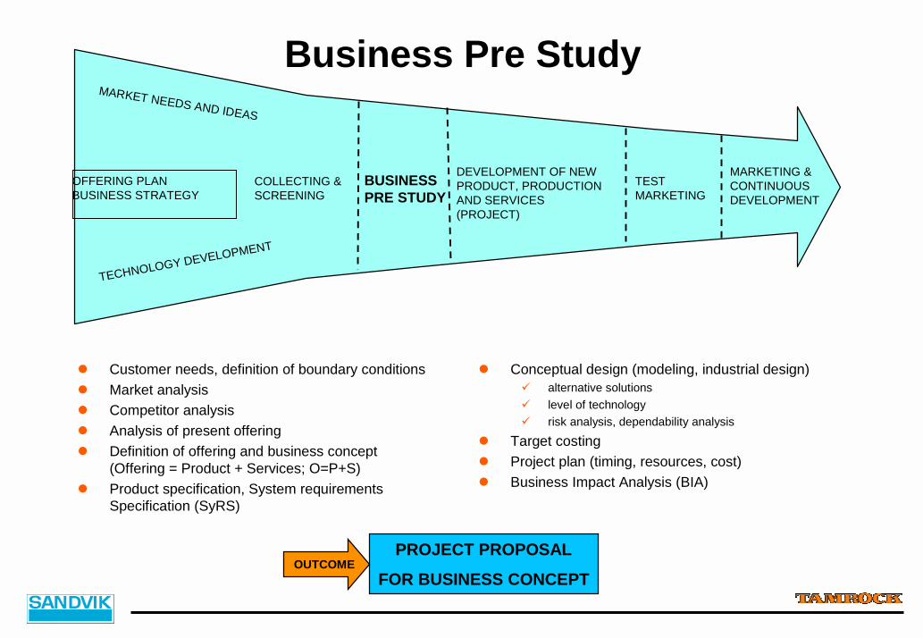
Business Pre Study
OFFERING PLANBUSINESS STRATEGY
COLLECTING &SCREENING
BUSINESSPRE STUDY
DEVELOPMENT OF NEWPRODUCT, PRODUCTIONAND SERVICES(PROJECT)
TESTMARKETING
MARKETING &CONTINUOUS DEVELOPMENT
TECHNOLOGY DEVELOPMENT
MARKET NEEDS AND IDEAS
! Customer needs, definition of boundary conditions! Market analysis! Competitor analysis! Analysis of present offering! Definition of offering and business concept
(Offering = Product + Services; O=P+S)! Product specification, System requirements
Specification (SyRS)
! Conceptual design (modeling, industrial design)# alternative solutions# level of technology# risk analysis, dependability analysis
! Target costing! Project plan (timing, resources, cost)! Business Impact Analysis (BIA)
OUTCOMEPROJECT PROPOSAL
FOR BUSINESS CONCEPT
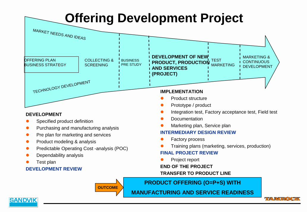
Offering Development Project
OFFERING PLANBUSINESS STRATEGY
COLLECTING &SCREENING
BUSINESSPRE STUDY
DEVELOPMENT OF NEWPRODUCT, PRODUCTIONAND SERVICES(PROJECT)
TESTMARKETING
MARKETING &CONTINUOUS DEVELOPMENT
TECHNOLOGY DEVELOPMENT
MARKET NEEDS AND IDEAS
DEVELOPMENT! Specified product definition! Purchasing and manufacturing analysis! Pre plan for marketing and services! Product modeling & analysis! Predictable Operating Cost -analysis (POC)! Dependability analysis! Test planDEVELOPMENT REVIEW
IMPLEMENTATION! Product structure! Prototype / product! Integration test, Factory acceptance test, Field test! Documentation! Marketing plan, Service planINTERMEDIARY DESIGN REVIEW! Factory process! Training plans (marketing, services, production)FINAL PROJECT REVIEW! Project reportEND OF THE PROJECTTRANSFER TO PRODUCT LINE
OUTCOMEPRODUCT OFFERING (O=P+S) WITH
MANUFACTURING AND SERVICE READINESS
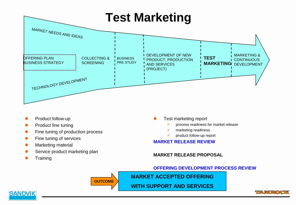
Test Marketing
OFFERING PLANBUSINESS STRATEGY
COLLECTING &SCREENING
BUSINESSPRE STUDY
DEVELOPMENT OF NEWPRODUCT, PRODUCTIONAND SERVICES(PROJECT)
TESTMARKETING
MARKETING &CONTINUOUS DEVELOPMENT
TECHNOLOGY DEVELOPMENT
MARKET NEEDS AND IDEAS
! Product follow-up! Product fine tuning! Fine tuning of production process! Fine tuning of services! Marketing material! Service product marketing plan! Training
! Test marketing report# process readiness for market release# marketing readiness# product follow-up report
MARKET RELEASE REVIEW
MARKET RELEASE PROPOSAL
OFFERING DEVELOPMENT PROCESS REVIEW
OUTCOMEMARKET ACCEPTED OFFERING
WITH SUPPORT AND SERVICES

SW Development as a Part ofthe Product Development Process
TYPICAL FEATURES OF SW PROJECTS! Project falls behind the schedule! End product does not fit to the requirements! Development costs are higher than expected! Reliability defects in products! Documents are not up to date
$ NEED TO DEVELOP SW PROCESS AND RESPECTIVE GUIDELINES! Initiation of SOFIA-project spring 1997! First guidelines ready autumn 1998! All new projects according to new process! Experiences even better than expected! $ Continuous Process Improvement
# new methods, guidelines and tools (OOD, UML, SE)# co-development together with partners

SOFtware In Automation (SOFIA)! Development process was analyzed with case studies
% 80% of identified defects caused by an inadequate requirement analysis phase! Optimum process was described! Work was directed to generate guidelines for:
# System Requirement Specifications (SyRS)# System Design Process# Software Requirement Specification (SRS)# Project Management
! The following standards and references were chosen as basics for the work:% IEEE 1233 Guide for Developing of System Requirements Specification% IEEE 830 Recommended Practice for Software requirement Specifications% IEEE 1062 Recommended Practice for Software Acquisition% ISO 9000-3 Guidelines for the application of ISO 9001 to the development, supply
and maintenance of software% ISO 10006 Quality Management – Guidelines to quality in Project Management% “Code Complete”, McConnell, S., Microsoft Press
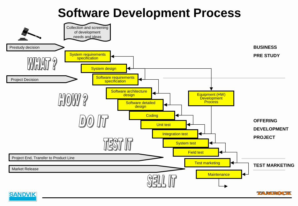
System test
Test marketing
Field test
Unit test
Coding
Software detaileddesign
Software requirementsspecification
Software Development ProcessCollection and screening
of developmentneeds and ideas
Prestudy decision
Project Decision
System requirementsspecification
System design
Software architecturedesign
Integration test
Project End, Transfer to Product Line
Maintenance
BUSINESS
PRE STUDY
Equipment (HW) Development
Process
OFFERING
DEVELOPMENT
PROJECT
TEST MARKETINGMarket Release
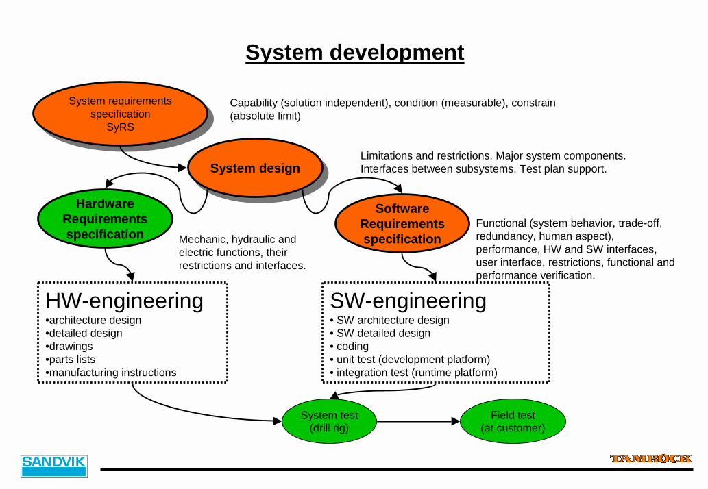
System requirementsspecification
SyRS
System requirementsspecification
SyRS
Capability (solution independent), condition (measurable), constrain (absolute limit)
System designSystem designLimitations and restrictions. Major system components. Interfaces between subsystems. Test plan support.
SoftwareRequirementsspecification
Functional (system behavior, trade-off, redundancy, human aspect), performance, HW and SW interfaces, user interface, restrictions, functional and performance verification.
HardwareRequirementsspecification Mechanic, hydraulic and
electric functions, their restrictions and interfaces.
HW-engineering•architecture design•detailed design•drawings•parts lists•manufacturing instructions
SW-engineering• SW architecture design• SW detailed design• coding• unit test (development platform)• integration test (runtime platform)
System development
System test(drill rig)
Field test(at customer)

CUSTOMER
BUSINESS SECTORS
ENVIRONMENT• Physical• Standards• Market• Organizational• Political• Cultural
TECHNICAL EXPERTS
• TECHNOLOGYCENTER
• ENGINEERING• PARTNERS
RAW REQUIREMENTS
CUSTOMER FEEDBACK
CUSTOMER REPRESENTATION
CONSTRAINT / INFLUENCETECHNICALREPRESENTATION
TECHNICAL FEEDBACK
OKREJECTION SyRSdocument
CONSTRAINT / INFLUENCE
FIELD EXPERIENCE
REVIEW
MARKET AREAS
PRODUCT LINE MANAGER
•SERVICE•PRODUCTION•PURCHASE
System RequirementsSpecification
SyRS
SyRS Process
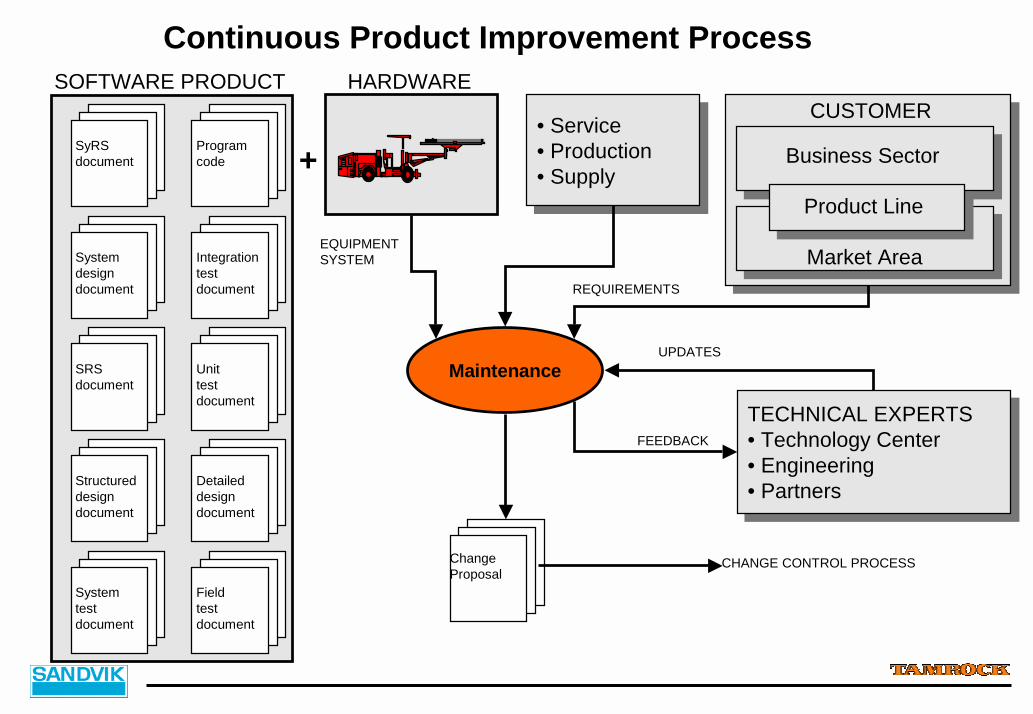
Maintenance
SOFTWARE PRODUCT
ChangeProposal
CHANGE CONTROL PROCESS
Continuous Product Improvement Process
Programcode
SyRSdocument
Systemdesigndocument
SRSdocument
Structureddesigndocument
Detaileddesigndocument
Unittestdocument
Integrationtestdocument
Systemtestdocument
Fieldtestdocument
UPDATES
TECHNICAL EXPERTS• Technology Center• Engineering• Partners
TECHNICAL EXPERTS• Technology Center• Engineering• Partners
FEEDBACK
CUSTOMER
Business Sector
Market Area
Product Line
REQUIREMENTS
• Service• Production• Supply
• Service• Production• Supply
EQUIPMENTSYSTEM
+
HARDWARE
3. AutoMine System Delivery Process
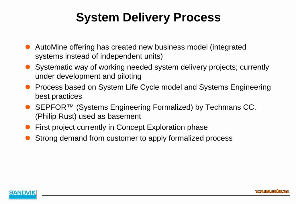
System Delivery Process
! AutoMine offering has created new business model (integrated systems instead of independent units)
! Systematic way of working needed system delivery projects; currently under development and piloting
! Process based on System Life Cycle model and Systems Engineeringbest practices
! SEPFOR™ (Systems Engineering Formalized) by Techmans CC. (Philip Rust) used as basement
! First project currently in Concept Exploration phase! Strong demand from customer to apply formalized process
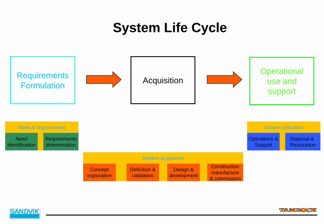
System Life Cycle
RequirementsFormulation
Need & requirements
NeedIdentification
Requirementsdetermination
System acquisition
Conceptexploration
Definition &validation
Design &development
Constructionmanufacture
& commission
System utilisation
Operations &Support
Disposal & Restoration
AcquisitionOperational
use andsupport
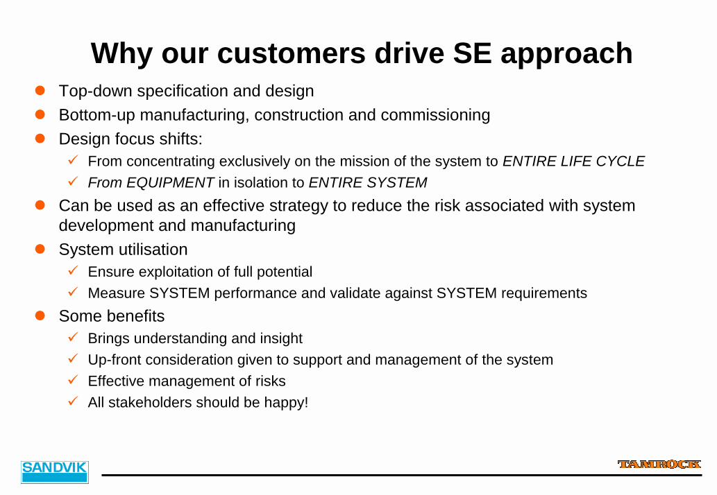
Why our customers drive SE approach! Top-down specification and design! Bottom-up manufacturing, construction and commissioning! Design focus shifts:
# From concentrating exclusively on the mission of the system to ENTIRE LIFE CYCLE# From EQUIPMENT in isolation to ENTIRE SYSTEM
! Can be used as an effective strategy to reduce the risk associated with system development and manufacturing
! System utilisation# Ensure exploitation of full potential# Measure SYSTEM performance and validate against SYSTEM requirements
! Some benefits# Brings understanding and insight# Up-front consideration given to support and management of the system# Effective management of risks# All stakeholders should be happy!

Evaluation&
Selection
Example ProjectConcept Exploration; Major deliverables
Need & requirements System acquisition
NeedIdentification
Requirementsdetermination
Conceptexploration
Definition &validation
Design &development
Constructionmanufacture
& commission
Cost effectivenessmodel
Systemspecification
Concep. Design 1Conventional
Concep. Design 2Autonomous
UserRequirementsSpecification
FunctionalArchitecture

Typical Massive Underground Mine Production System
TransferPoint
Drawpoint
ExtractionTunnel
RimTunnel
HaulageTunnel
CrusherBins
TransferPoint
Ore Extraction
System
Ore Transportation
System
OreHoisting System
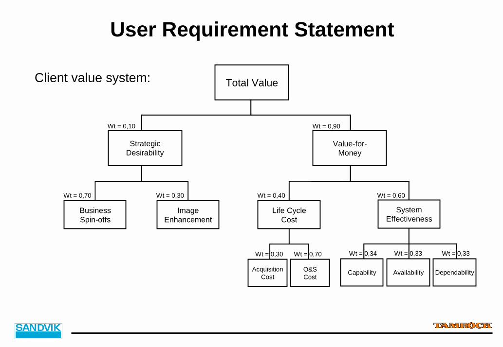
User Requirement Statement
Client value system: Total Value
Value-for-Money
Wt = 0,90
StrategicDesirability
Wt = 0,10
Wt = 0,70 Wt = 0,30 Wt = 0,40
SystemEffectiveness
Wt = 0,60
AcquisitionCost
Wt = 0,30
O&SCost
Wt = 0,70
Availability
Wt = 0,33
Capability
Wt = 0,34
Dependability
Wt = 0,33
Life CycleCost
ImageEnhancement
BusinessSpin-offs
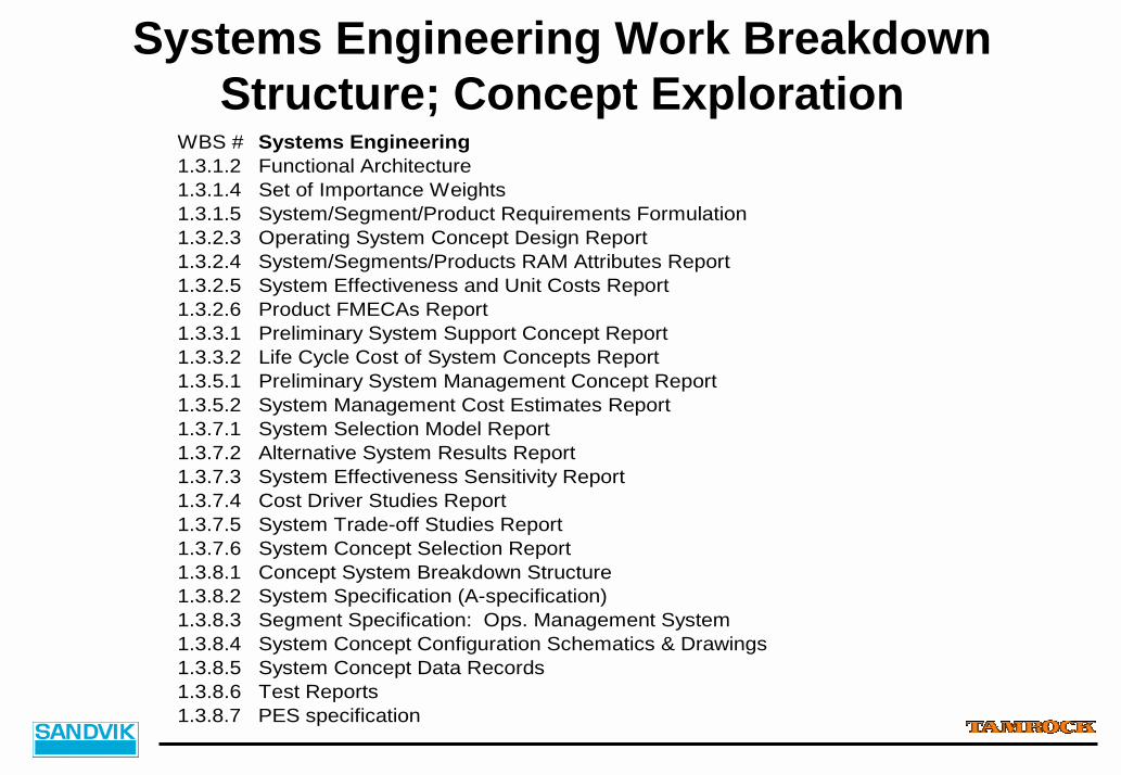
Systems Engineering Work Breakdown Structure; Concept Exploration
WBS # Systems Engineering1.3.1.2 Functional Architecture1.3.1.4 Set of Importance Weights1.3.1.5 System/Segment/Product Requirements Formulation1.3.2.3 Operating System Concept Design Report1.3.2.4 System/Segments/Products RAM Attributes Report1.3.2.5 System Effectiveness and Unit Costs Report1.3.2.6 Product FMECAs Report1.3.3.1 Preliminary System Support Concept Report1.3.3.2 Life Cycle Cost of System Concepts Report1.3.5.1 Preliminary System Management Concept Report1.3.5.2 System Management Cost Estimates Report1.3.7.1 System Selection Model Report1.3.7.2 Alternative System Results Report1.3.7.3 System Effectiveness Sensitivity Report1.3.7.4 Cost Driver Studies Report1.3.7.5 System Trade-off Studies Report1.3.7.6 System Concept Selection Report1.3.8.1 Concept System Breakdown Structure1.3.8.2 System Specification (A-specification)1.3.8.3 Segment Specification: Ops. Management System1.3.8.4 System Concept Configuration Schematics & Drawings1.3.8.5 System Concept Data Records1.3.8.6 Test Reports1.3.8.7 PES specification
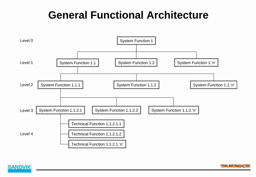
General Functional Architecture
System Function 1.1.2System Function 1.1.1 System Function 1.1.‘n’
System Function 1
System Function 1.2System Function 1.1 System Function 1.‘n’
System Function 1.1.2.2System Function 1.1.2.1 System Function 1.1.2.’n’
Technical Function 1.1.2.1.2
Technical Function 1.1.2.1.1
Technical Function 1.1.2.1.‘n’
Level 0
Level 1
Level 2
Level 4
Level 3
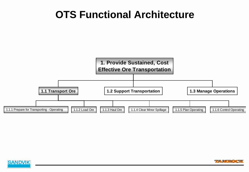
OTS Functional Architecture
1. Provide Sustained, CostEffective Ore Transportation
1.1.1 Prepare for Transporting - Operating 1.1.2 Load Ore 1.1.3 Haul Ore 1.1.6 Control Operating
1.1 Transport Ore 1.2 Support Transportation 1.3 Manage Operations
1.1.4 Clear Minor Spillage 1.1.5 Plan Operating
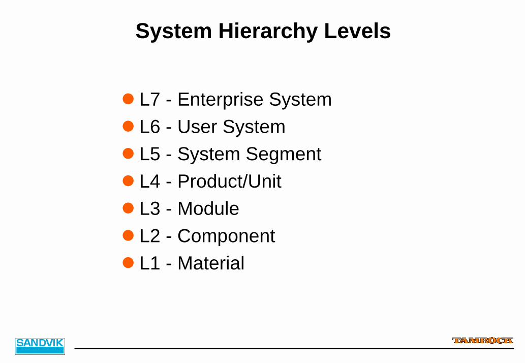
System Hierarchy Levels
! L7 - Enterprise System! L6 - User System! L5 - System Segment! L4 - Product/Unit! L3 - Module! L2 - Component! L1 - Material
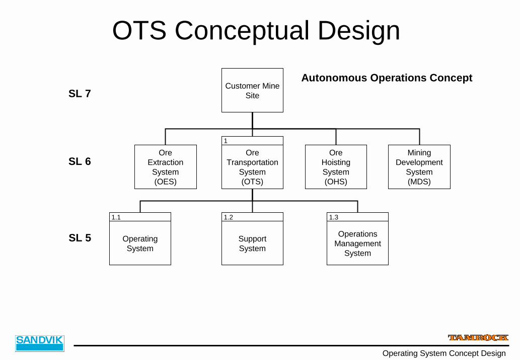
Operating System Concept Design
Autonomous Operations Concept
OreTransportation
System(OTS)
SL 7
SL 6Ore
HoistingSystem(OHS)
OreExtractionSystem(OES)
SupportSystem
OperatingSystem
OperationsManagement
System
SL 5
Customer MineSite
1.1 1.2 1.3
1
MiningDevelopment
System(MDS)
OTS Conceptual Design

Operating System Concept Design
Autonomous Operations Concept
OperatingSystem
SL 5
SL 5.1
1.1
LoadingSystem
1.1.1
HaulingSystem
1.1.2
OperatingPlanningSystem
1.1.3
OperatingControlSystem
1.1.4
Operating Segment
OTS Conceptual Design
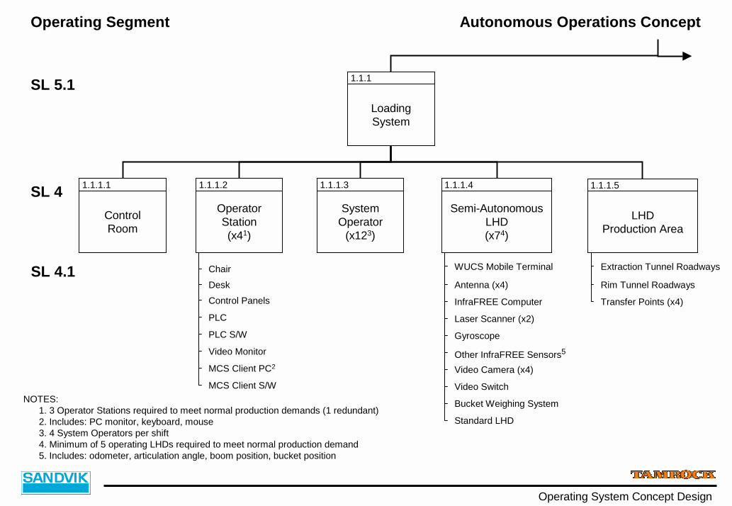
Operating System Concept Design
Autonomous Operations Concept
SL 5.1
SL 4
SL 4.1
LoadingSystem
OperatorStation(x41)
SystemOperator
(x123)
Semi-AutonomousLHD(x74)
ControlRoom
Control Panels
PLC
PLC S/W
Video Monitor
MCS Client PC2
MCS Client S/W
WUCS Mobile Terminal
InfraFREE Computer
Video Switch
Bucket Weighing System
Antenna (x4)
Standard LHD
1.1.1
1.1.1.2 1.1.1.3 1.1.1.41.1.1.1
LHDProduction Area
1.1.1.5
ChairDesk
Laser Scanner (x2)
Gyroscope
Other InfraFREE Sensors5
Video Camera (x4)
NOTES:1. 3 Operator Stations required to meet normal production demands (1 redundant)2. Includes: PC monitor, keyboard, mouse3. 4 System Operators per shift4. Minimum of 5 operating LHDs required to meet normal production demand5. Includes: odometer, articulation angle, boom position, bucket position
Extraction Tunnel Roadways
Transfer Points (x4)
Rim Tunnel Roadways
Operating Segment
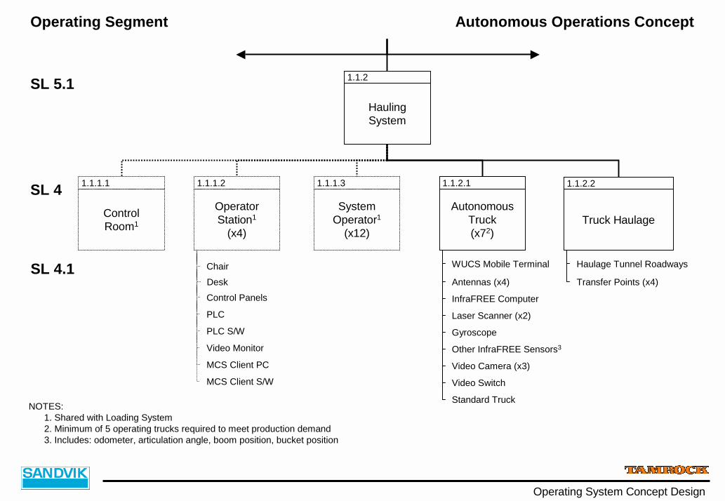
Operating System Concept Design
Autonomous Operations Concept
SL 5.1
SL 4
SL 4.1
HaulingSystem
OperatorStation1
(x4)
SystemOperator1
(x12)
ControlRoom1
Control Panels
PLC
PLC S/W
Video Monitor
MCS Client PC
MCS Client S/W
1.1.2
1.1.1.2 1.1.1.31.1.1.1
AutonomousTruck(x72)
WUCS Mobile Terminal
InfraFREE Computer
Standard Truck
Antennas (x4)
1.1.2.1
Truck Haulage
1.1.2.2
ChairDesk
Video Switch
Laser Scanner (x2)
Gyroscope
Other InfraFREE Sensors3
Video Camera (x3)
NOTES:1. Shared with Loading System2. Minimum of 5 operating trucks required to meet production demand3. Includes: odometer, articulation angle, boom position, bucket position
Haulage Tunnel Roadways
Transfer Points (x4)
Operating Segment

4. Summary
Summary
! Trend in mining business towards wider and more integrated process systems
! Expanding use of modern IT technology! Tightening quality and productivity requirements! Partnering in development; multi site projects! Need to compress development times! "Offering Development and Delivery Processes have to be well
defined! Systems Engineering Approach fits well to existing ODP! Full potential of SE not exploited yet

Thank You
Questions & Comments Please