Embed Size (px)
Citation preview
Applying Merging Convetional Marker and Backpropagation
Neural Network in QR Code Augmented Reality Tracking
Gia M. Agusta1,3
, Khodijah Hulliyah1, Arini
1, Rizal Broer Bahaweres
1,2,4
1. Department of Computer Science, Faculty of Science and Technology, State Islamic
University Syarif Hidayatullah, Jakarta, 15419, Indonesia
2. Graduated Program of Electrical Engineering Department, Mercu Buana University,
Jakarta, 11650, Indonesia
3. AR&Co. Augmented Reality and Innovative Technology, Jakarta, 11530, Indonesia
4. Department of Informatics, Institute of Technology, Bandung, 40132, Indonesia
Emails: [email protected], [email protected], [email protected], [email protected]
Submitted: June 21, 2013 Accepted: Sep. 30, 2013 Published: Dec. 16, 2013
Abstract- Usability of QR Code in Augmented Reality system has been used for digital content
accessible publicly. However, QR Code in AR system still has imprecision tracking. In this article
we propose merging QR Code within conventional marker and backpropagation neural network
(BPNN) algorithm to recognizing QR Code Finder Pattern. The method which our chosen to
approaching conventional marker. The result of BPNN testing, QRFP detected in perspective
distortion with ID-encoded character length 78, 53 and 32. The result has accuracy of 6DOF
±10.65º pitching, ±15.03° yawing and ±408.07 surging, marker stability has 97.625% and
computation time runs at 35.41 fps.
Index terms: Augmented Reality, QR Code, QR Code Finder Pattern Detection, Tracking, 6 DOF,
Backpropagation, Neural Network.
INTERNATIONAL JOURNAL ON SMART SENSING AND INTELLIGENT SYSTEMS VOL. 6, NO. 5, DECEMBER 2013
1918
I. INTRODUCTION
Currently, applications development of Augmented Reality (AR) are rapidly making the
needed of digital contents can be accessed publicly. Thus, many tracking method appear in
AR system to facilitate the development AR and user usage needed. Along with many QR
Code usability and user usage on mobile device, QR Code usage has been used for digital
content accessible publicly, however QR Code tracking in AR system is still have problem.
QR Code Augmented Reality (QRAR) is an AR applying the QR Code as marker-based
tracking. The QRAR does not require pre-registration process, it has a combination number
of 107089
ID-encoded and can be used on public AR application [1] [2]. A marker does not
require small size to ease tracking, marker-based tracking has small computation power [3]
and require real-time and accurate 6 Degree of Freedom (6 DOF) pose tracking [4].
Tracking method with three pattern in QR Code detection or called QR Code Finder Pattern
(QRFP) has been proposed by several researcher in their method such as simple count
mechanism [1], contour filtering [2] and binary histogram [5].
QRFP Detection with simple count mechanism has fast speed tracking but limited 6 DOF
pose tracking, thick border to detect three QRFP together in perspective position and
intersection between two line equation from detected QRFP unstable because QRFP in scene
more small if three QRFP should be detected together so it would difficult to determining 4th
virtual point of three QRFP and occasionally not all QRFP detected, so a pose estimation
would highly impacted on 6 DOF accuracy and 3D Augmentation. Contour filtering has
simple mechanism, however that method has limited 6 DOF pose tracking and heavy
computational power. Binary histogram has fast enough speed tracking, stable tracking, but
still depend on planar object with Optical Flow method.
Backpropagation Neural Network (BPNN) is Neural Network Multilayer Perceptron which
can solve complex function or non-linear, easy to use for supervise learning, fault tolerance
[6] and it can recognizing pattern [7].
In this case, we propose to merging conventional marker with QR Code, we called it QR
Code marker, so QRFP will be in thick border and more easy to detect. Nevertheless, in the
AR case the marker should be projected from perspective view and it will cause noise on
QRFP image, we also to propose Backpropagation approach method to recognize three QRFP
those have occurred damage or noise. In this paper, we will measure accuracy of 6 DOF and
computational speed while tracking.
Gia M. Agusta, Khodijah Hulliyah, Arini, Rizal Broer Bahaweres, APPLYING MERGING CONVETIONAL MARKER AND BACKPROPAGATION NEURAL NETWORK IN QR CODE AUGMENTED REALITY TRACKING
1919
II. QR Code Augmented Reality
In the context of the field of Augmented Reality, AR systems generally require the
registration of an earlier marker pattern, so the system can identify markers and content
augmentation. With a QR Code, marker can be scaned and decoded by the system, the system
can download content from the internet. It does not require registration process.
Mark Fiala developed an AR marker in ARTag [8], with ID-encoded marker-based system.
The system uses techniques decode marker, but it still has a limited number of markers. Then
Webtag Fiala developed to address these issues. Webtag [9] can handle 4x10¹²
marker, but
that number is still less than 7089 characters or 107089
different encoding that can be handled
by QR Code. Thus the QR Code can be solve the issue. Marker comparison table can be see
at Tabel 1.
In conventional AR system need to design a marker for tracking, of course to creating system
with big environment and using in public user need big cost to handle it. At present, QR Code
have been used by many user because QR Code has advantages than other 2D Barcode and
many library or SDK can be used freely by many developer. QR Code clearly has many
potential than using conventional marker [10].
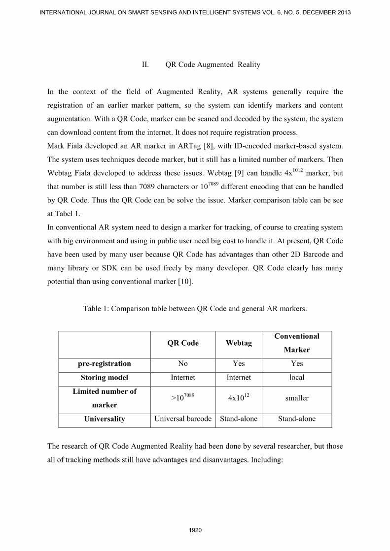
Table 1: Comparison table between QR Code and general AR markers.
QR Code Webtag Conventional
Marker
pre-registration No Yes Yes
Storing model Internet Internet local
Limited number of
marker >10
7089 4x10
12 smaller
Universality Universal barcode Stand-alone Stand-alone
The research of QR Code Augmented Reality had been done by several researcher, but those
all of tracking methods still have advantages and disanvantages. Including:
INTERNATIONAL JOURNAL ON SMART SENSING AND INTELLIGENT SYSTEMS VOL. 6, NO. 5, DECEMBER 2013
1920
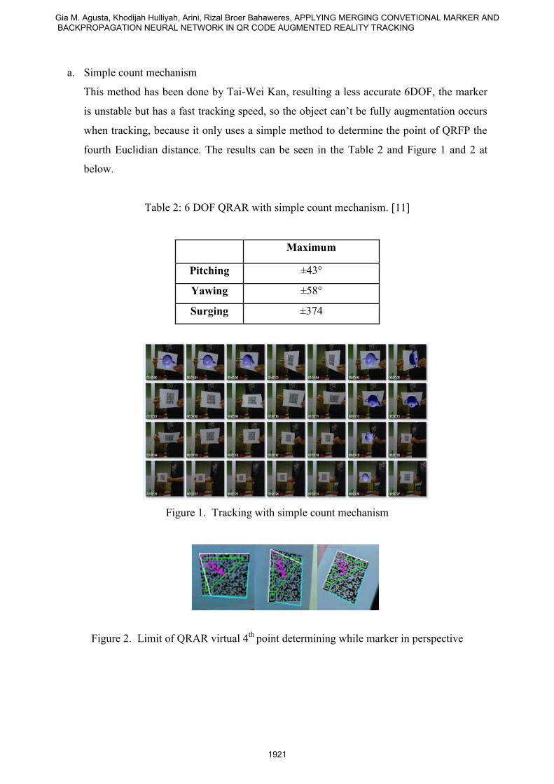
a. Simple count mechanism
This method has been done by Tai-Wei Kan, resulting a less accurate 6DOF, the marker
is unstable but has a fast tracking speed, so the object can’t be fully augmentation occurs
when tracking, because it only uses a simple method to determine the point of QRFP the
fourth Euclidian distance. The results can be seen in the Table 2 and Figure 1 and 2 at
below.
Table 2: 6 DOF QRAR with simple count mechanism. [11]
Maximum
Pitching ±43°
Yawing ±58°
Surging ±374
Figure 1. Tracking with simple count mechanism
Figure 2. Limit of QRAR virtual 4th
point determining while marker in perspective
Gia M. Agusta, Khodijah Hulliyah, Arini, Rizal Broer Bahaweres, APPLYING MERGING CONVETIONAL MARKER AND BACKPROPAGATION NEURAL NETWORK IN QR CODE AUGMENTED REALITY TRACKING
1921
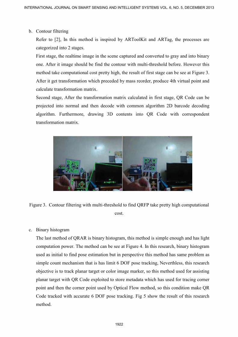
b. Contour filtering
Refer to [2], In this method is inspired by ARToolKit and ARTag, the processes are
categorized into 2 stages.
First stage, the realtime image in the scene captured and converted to gray and into binary
one. After it image should be find the contour with multi-threshold before. However this
method take computational cost pretty high, the result of first stage can be see at Figure 3.
After it get transformation which preceded by mass reorder, produce 4th virtual point and
calculate transformation matrix.
Second stage, After the transformation matrix calculated in first stage, QR Code can be
projected into normal and then decode with common algorithm 2D barcode decoding
algorithm. Furthermore, drawing 3D contents into QR Code with correspondent
transformation matrix.
Figure 3. Contour filtering with multi-threshold to find QRFP take pretty high computational
cost.
c. Binary histogram
The last method of QRAR is binary histogram, this method is simple enough and has light
computation power. The method can be see at Figure 4. In this research, binary histogram
used as initial to find pose estimation but in perspective this method has same problem as
simple count mechanism that is has limit 6 DOF pose tracking, Neverthless, this research
objective is to track planar target or color image marker, so this method used for assisting
planar target with QR Code exploited to store metadata which has used for tracing corner
point and then the corner point used by Optical Flow method, so this condition make QR
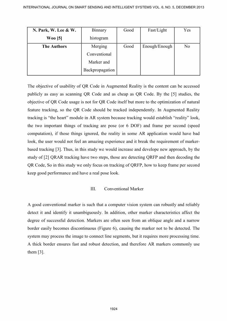
Code tracked with accurate 6 DOF pose tracking. Fig 5 show the result of this research
method.
INTERNATIONAL JOURNAL ON SMART SENSING AND INTELLIGENT SYSTEMS VOL. 6, NO. 5, DECEMBER 2013
1922
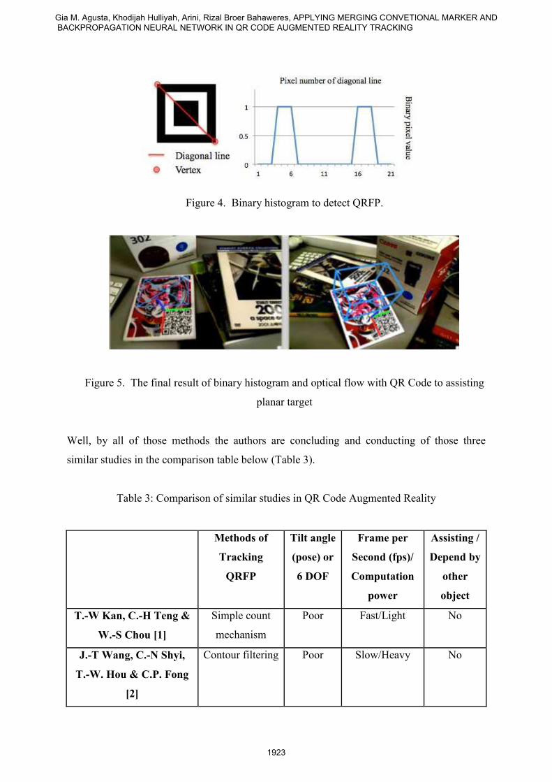
Figure 4. Binary histogram to detect QRFP.
Figure 5. The final result of binary histogram and optical flow with QR Code to assisting
planar target
Well, by all of those methods the authors are concluding and conducting of those three
similar studies in the comparison table below (Table 3).
Table 3: Comparison of similar studies in QR Code Augmented Reality
Methods of
Tracking
QRFP
Tilt angle
(pose) or
6 DOF
Frame per
Second (fps)/
Computation
power
Assisting /
Depend by
other
object
T.-W Kan, C.-H Teng &
W.-S Chou [1]
Simple count
mechanism
Poor Fast/Light No
J.-T Wang, C.-N Shyi,
T.-W. Hou & C.P. Fong
[2]
Contour filtering Poor Slow/Heavy No
Gia M. Agusta, Khodijah Hulliyah, Arini, Rizal Broer Bahaweres, APPLYING MERGING CONVETIONAL MARKER AND BACKPROPAGATION NEURAL NETWORK IN QR CODE AUGMENTED REALITY TRACKING
1923
N. Park, W. Lee & W.
Woo [5]
Binnary
histogram
Good Fast/Light Yes
The Authors Merging
Conventional
Marker and
Backpropagation
Good Enough/Enough No
The objective of usability of QR Code in Augmented Reality is the content can be accessed
publicly as easy as scanning QR Code and as cheap as QR Code. By the [5] studies, the
objective of QR Code usage is not for QR Code itself but more to the optimization of natural
feature tracking, so the QR Code should be tracked independently. In Augmented Reality
tracking is “the heart” module in AR system because tracking would establish “reality” look,
the two important things of tracking are pose (or 6 DOF) and frame per second (speed
computation), if those things ignored, the reality in some AR application would have bad
look, the user would not feel an amazing experience and it break the requirement of marker-
based tracking [3]. Thus, in this study we would increase and develope new approach, by the
study of [2] QRAR tracking have two steps, those are detecting QRFP and then decoding the
QR Code, So in this study we only focus on tracking of QRFP, how to keep frame per second
keep good performance and have a real pose look.
III. Conventional Marker
A good conventional marker is such that a computer vision system can robustly and reliably
detect it and identify it unambiguously. In addition, other marker characteristics affect the
degree of successful detection. Markers are often seen from an oblique angle and a narrow
border easily becomes discontinuous (Figure 6), causing the marker not to be detected. The
system may process the image to connect line segments, but it requires more processing time.
A thick border ensures fast and robust detection, and therefore AR markers commonly use
them [3].
INTERNATIONAL JOURNAL ON SMART SENSING AND INTELLIGENT SYSTEMS VOL. 6, NO. 5, DECEMBER 2013
1924
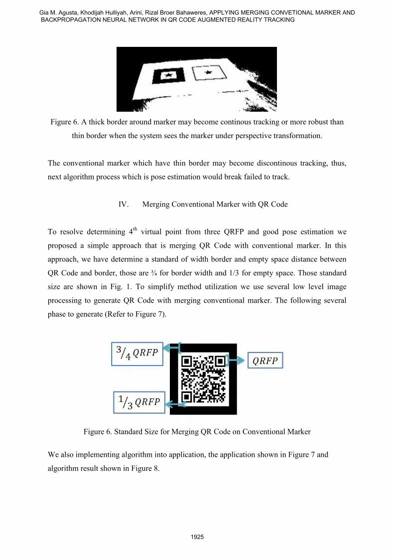
Figure 6. A thick border around marker may become continous tracking or more robust than
thin border when the system sees the marker under perspective transformation.
The conventional marker which have thin border may become discontinous tracking, thus,
next algorithm process which is pose estimation would break failed to track.
IV. Merging Conventional Marker with QR Code
To resolve determining 4th
virtual point from three QRFP and good pose estimation we
proposed a simple approach that is merging QR Code with conventional marker. In this
approach, we have determine a standard of width border and empty space distance between
QR Code and border, those are ¾ for border width and 1/3 for empty space. Those standard
size are shown in Fig. 1. To simplify method utilization we use several low level image
processing to generate QR Code with merging conventional marker. The following several
phase to generate (Refer to Figure 7).
Figure 6. Standard Size for Merging QR Code on Conventional Marker
We also implementing algorithm into application, the application shown in Figure 7 and
algorithm result shown in Figure 8.
Gia M. Agusta, Khodijah Hulliyah, Arini, Rizal Broer Bahaweres, APPLYING MERGING CONVETIONAL MARKER AND BACKPROPAGATION NEURAL NETWORK IN QR CODE AUGMENTED REALITY TRACKING
1925
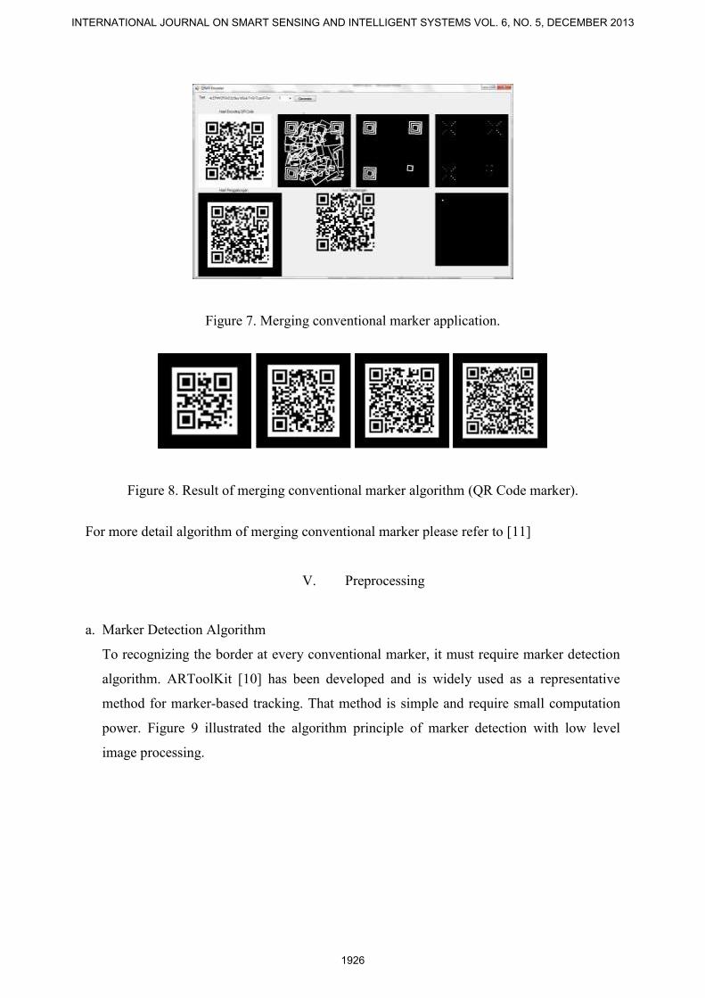
Figure 7. Merging conventional marker application.
Figure 8. Result of merging conventional marker algorithm (QR Code marker).
For more detail algorithm of merging conventional marker please refer to [11]
V. Preprocessing
a. Marker Detection Algorithm
To recognizing the border at every conventional marker, it must require marker detection
algorithm. ARToolKit [10] has been developed and is widely used as a representative
method for marker-based tracking. That method is simple and require small computation
power. Figure 9 illustrated the algorithm principle of marker detection with low level
image processing.
INTERNATIONAL JOURNAL ON SMART SENSING AND INTELLIGENT SYSTEMS VOL. 6, NO. 5, DECEMBER 2013
1926
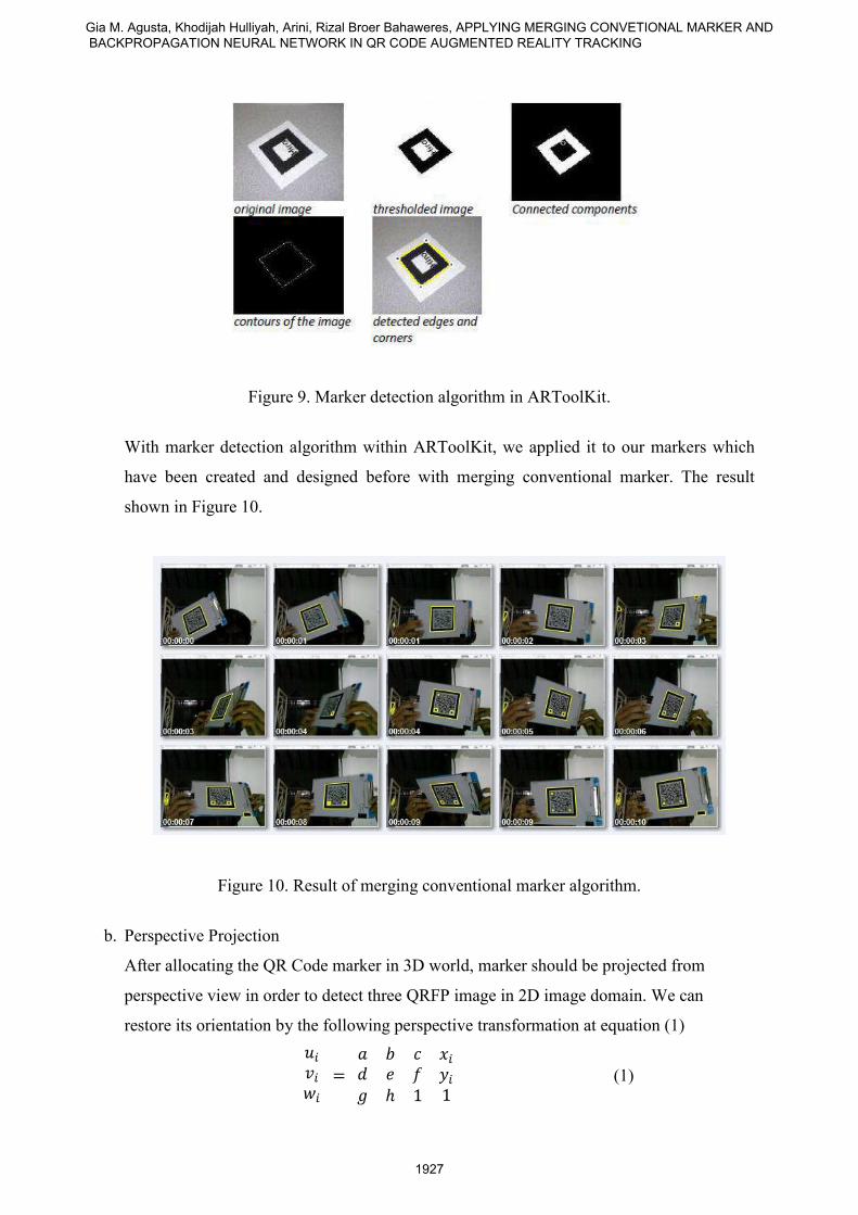
Figure 9. Marker detection algorithm in ARToolKit.
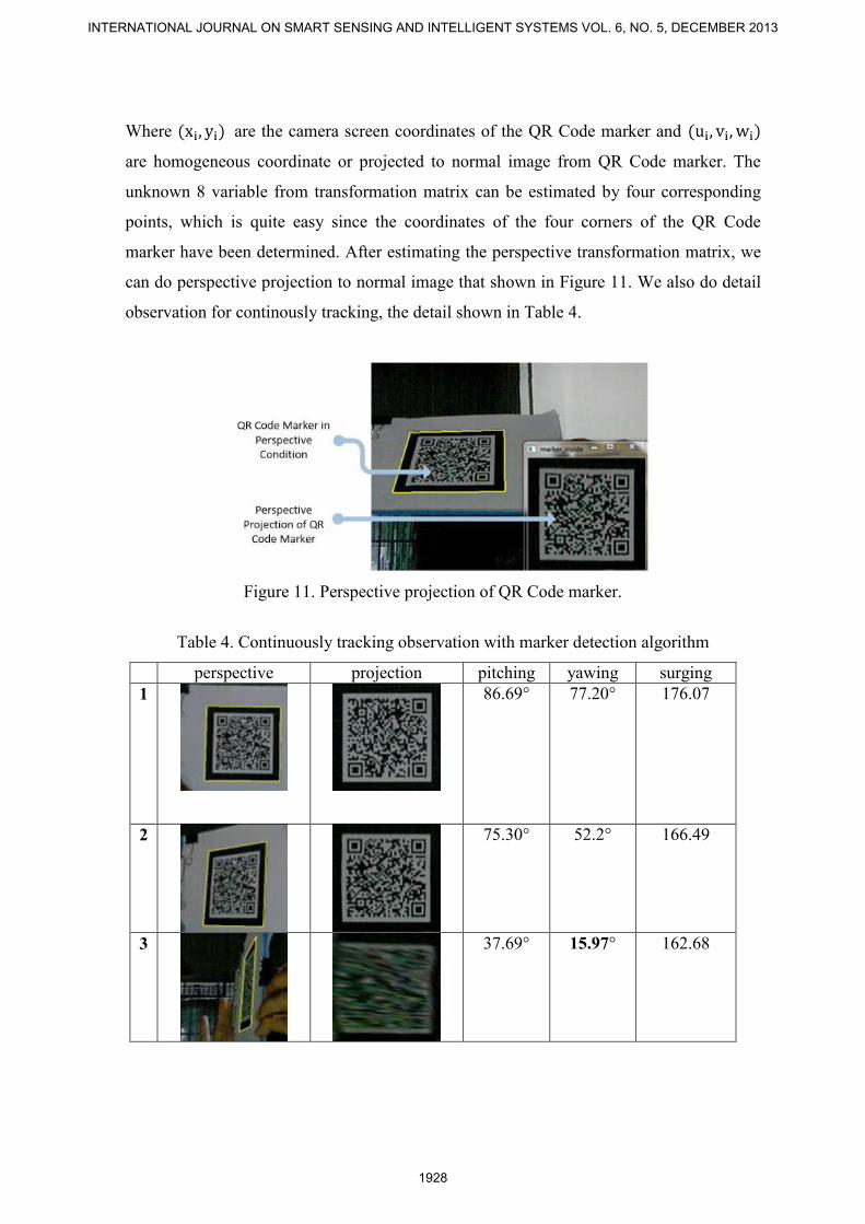
With marker detection algorithm within ARToolKit, we applied it to our markers which
have been created and designed before with merging conventional marker. The result
shown in Figure 10.
Figure 10. Result of merging conventional marker algorithm.
b. Perspective Projection
After allocating the QR Code marker in 3D world, marker should be projected from
perspective view in order to detect three QRFP image in 2D image domain. We can
restore its orientation by the following perspective transformation at equation (1)
(1)
Gia M. Agusta, Khodijah Hulliyah, Arini, Rizal Broer Bahaweres, APPLYING MERGING CONVETIONAL MARKER AND BACKPROPAGATION NEURAL NETWORK IN QR CODE AUGMENTED REALITY TRACKING
1927
Where are the camera screen coordinates of the QR Code marker and
are homogeneous coordinate or projected to normal image from QR Code marker. The
unknown 8 variable from transformation matrix can be estimated by four corresponding
points, which is quite easy since the coordinates of the four corners of the QR Code
marker have been determined. After estimating the perspective transformation matrix, we
can do perspective projection to normal image that shown in Figure 11. We also do detail
observation for continously tracking, the detail shown in Table 4.
Figure 11. Perspective projection of QR Code marker.
Table 4. Continuously tracking observation with marker detection algorithm
perspective projection pitching yawing surging
1
86.69° 77.20° 176.07
2
75.30° 52.2° 166.49
3
37.69° 15.97° 162.68
INTERNATIONAL JOURNAL ON SMART SENSING AND INTELLIGENT SYSTEMS VOL. 6, NO. 5, DECEMBER 2013
1928
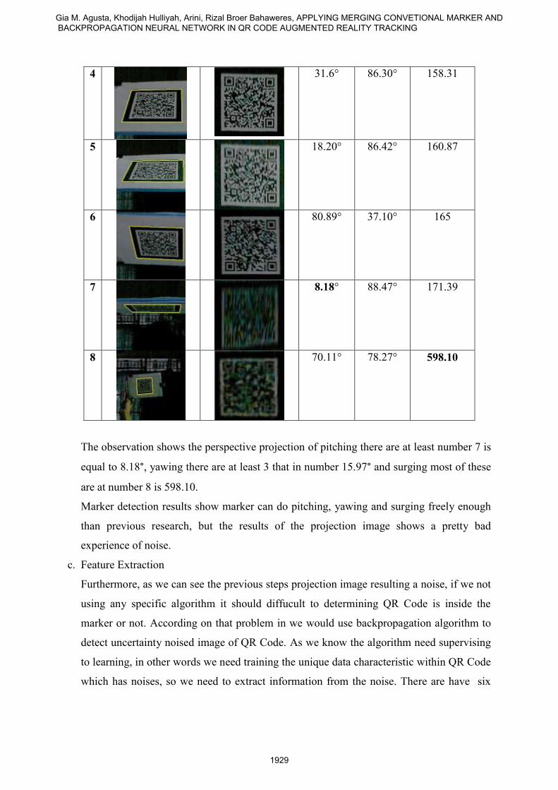
4
31.6° 86.30° 158.31
5
18.20° 86.42° 160.87
6
80.89° 37.10° 165
7
8.18° 88.47° 171.39
8
70.11° 78.27° 598.10
The observation shows the perspective projection of pitching there are at least number 7 is
equal to 8.18°, yawing there are at least 3 that in number 15.97° and surging most of these
are at number 8 is 598.10.
Marker detection results show marker can do pitching, yawing and surging freely enough
than previous research, but the results of the projection image shows a pretty bad
experience of noise.
c. Feature Extraction
Furthermore, as we can see the previous steps projection image resulting a noise, if we not
using any specific algorithm it should diffucult to determining QR Code is inside the
marker or not. According on that problem in we would use backpropagation algorithm to
detect uncertainty noised image of QR Code. As we know the algorithm need supervising
to learning, in other words we need training the unique data characteristic within QR Code
which has noises, so we need to extract information from the noise. There are have six
Gia M. Agusta, Khodijah Hulliyah, Arini, Rizal Broer Bahaweres, APPLYING MERGING CONVETIONAL MARKER AND BACKPROPAGATION NEURAL NETWORK IN QR CODE AUGMENTED REALITY TRACKING
1929
variable or six unique charateristic what we would take for feature extraction, the variable
are listed below:
(1) White color percentage,
(2) Black color percentage,
(3) Number of countour,
(4) Contour graylevel,
(5) x coordinate and,
(6) y coordinate graylevel location
To reach the research goal of 6DOF tracking accuracy, QRFP should be detected, however
the problem are three QRFP have noise, several sample of noise are shown in Table 2 on
projection column. In that case we use feature extraction approach with low level image
processing, including morphology and segmentation. In the principle, these methods are
similary with marker detection algorithm, however the different is at the usability of
output information.
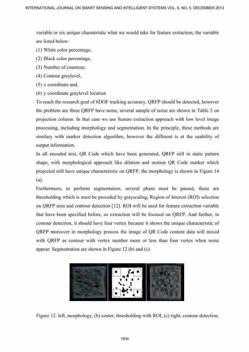
In all encoded text, QR Code which have been generated, QRFP still in static pattern
shape, with morphological approach like dilation and erotion QR Code marker which
projected still have unique characteristic on QRFP, the morphology is shown in Figure 14
(a).
Furthermore, to perform segmentation, several phase must be passed, those are
thresholding which is must be preceded by grayscaling, Region of Interest (ROI) selection
on QRFP area and contour detection [12]. ROI will be used for feature extraction variable
that have been specified before, so extraction will be focused on QRFP. And further, in
contour detection, it should have four vertex because it shows the unique characteristic of
QRFP moreover in morphology process the image of QR Code content data will mixed
with QRFP as contour with vertex number more or less than four vertex when noise
appear. Segmentation are shown in Figure 12 (b) and (c).
Figure 12. left, morphology, (b) center, thresholding with ROI, (c) right, contour detection.
INTERNATIONAL JOURNAL ON SMART SENSING AND INTELLIGENT SYSTEMS VOL. 6, NO. 5, DECEMBER 2013
1930
VI. QRFP Detection with Backpropagation Neural Network
a. Sample data training collection
In the case of this research is the data to be retrieved the data from the image that runs in
real-time from the real world, the image would appear to be strongly affected by many
variables such as light noise, contrast, blur and the other by the number of frames that are
not known before, then the case of image data population is unknown and the sample size
was also not known, so we use a non-probability sampling design, where the sampling
design of the total population is unknown with certainty and great opportunities for
population data members elected as unknown samples [13]. Sampling data retrieval
techniques are divided into two sampling techniques for the training set and a test set.
The data collection sampling techniques to be used, but the author saw several conditions
and considerations that must be considered include:
(1) The number of data samples taken must be adapted to the method of data analysis, the
neural network method of sample data that would be overtraining occured if the data
too much [19], and the pattern would not be recognized by neural network or data
can’t be representative of the population if using a little of data. These considerations
were also an influence writers to choose non-probability sampling design.
(2) Marker in the image projected to the normal form produces 4 image orientation [8]
(3) The process of detection / recognition QRFP pattern should be able to acceptance and
rejection on the target marker [3].
Therefore in this study we use judgment or purposive sampling technique that is sampling
with consideration of something [15]. According to several conditions, the data processing
is done by categorizing, categories include the following 5 conditions perspective, 4
orientations and 2 targets . Each was taken by 5 data, the total number of sample data for
training set is equal to (5 x 4 orientation perspective condition x 5 data samples) 100 data
for each target then the total of 200 data.
Then the sampling data retrieval technique to test sets are used convenience sampling, that
is a technique that is not focused to the generalization of data, quickly, easily and
inexpensively. Consideration of using this technique because it would test the results of
generalization of data samples from the training set or the test results of pattern
recognition outside the training data set as a general procedure of analysis with
backpropagation method. For processing in the test set do the same thing with the training
set and for the size according to the size of the technical convenience of data obtained
Gia M. Agusta, Khodijah Hulliyah, Arini, Rizal Broer Bahaweres, APPLYING MERGING CONVETIONAL MARKER AND BACKPROPAGATION NEURAL NETWORK IN QR CODE AUGMENTED REALITY TRACKING
1931
through by researchers [15].
Each sample data is the data vector of the predictor variable 6x4 / data elements, then there
is a sample of 200 or 4800 x 24 input elements. Predictor variables were multiplied by 4 is
a backup variable, so that the results can be tolerated ANN prediction or classification
more accurate. The data sample is expected to be representative of the population data.
Especially for the training set. To produce good accuracy 6DOF then capture the data will
be drawn from a number of conditions and considerations that have been discussed in the
research methodology chapter, a detailed consideration of them.
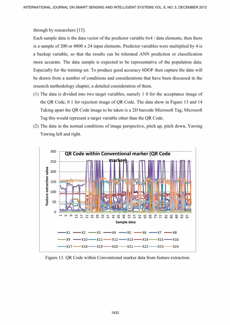
(1) The data is divided into two target variables, namely 1 0 for the acceptance image of
the QR Code, 0 1 for rejection image of QR Code. The data show in Figure 13 and 14
Taking apart the QR Code image to be taken is a 2D barcode Microsoft Tag, Microsoft
Tag this would represent a target variable other than the QR Code.
(2) The data in the normal conditions of image perspective, pitch up, pitch down, Yawing
Yawing left and right.
Figure 13. QR Code within Conventional marker data from feature extraction.
0
50
100
150
200
250
300
1 5 9
13
17
21
25
29
33
37
41
45
49
53
57
61
65
69
73
77
81
85
89
93
97
Feat
ure
ext
ract
ion
val
ue
Sample data
QR Code within Conventional marker (QR Code marker)
X1 X2 X3 X4 X5 X6 X7 X8
X9 X10 X11 X12 X13 X14 X15 X16
X17 X18 X19 X20 X21 X22 X23 X24
INTERNATIONAL JOURNAL ON SMART SENSING AND INTELLIGENT SYSTEMS VOL. 6, NO. 5, DECEMBER 2013
1932
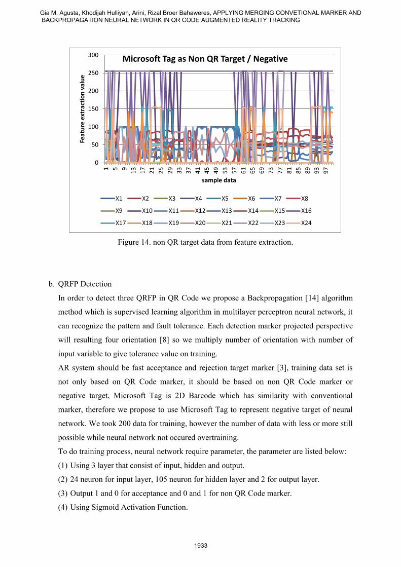
Figure 14. non QR target data from feature extraction.
b. QRFP Detection
In order to detect three QRFP in QR Code we propose a Backpropagation [14] algorithm
method which is supervised learning algorithm in multilayer perceptron neural network, it
can recognize the pattern and fault tolerance. Each detection marker projected perspective
will resulting four orientation [8] so we multiply number of orientation with number of
input variable to give tolerance value on training.
AR system should be fast acceptance and rejection target marker [3], training data set is
not only based on QR Code marker, it should be based on non QR Code marker or
negative target, Microsoft Tag is 2D Barcode which has similarity with conventional
marker, therefore we propose to use Microsoft Tag to represent negative target of neural
network. We took 200 data for training, however the number of data with less or more still
possible while neural network not occured overtraining.
To do training process, neural network require parameter, the parameter are listed below:
(1) Using 3 layer that consist of input, hidden and output.
(2) 24 neuron for input layer, 105 neuron for hidden layer and 2 for output layer.
(3) Output 1 and 0 for acceptance and 0 and 1 for non QR Code marker.
(4) Using Sigmoid Activation Function.
0
50
100
150
200
250
300
1 5 9
13
17
21
25
29
33
37
41
45
49
53
57
61
65
69
73
77
81
85
89
93
97
Feat
ure
ext
ract
ion
val
ue
sample data
Microsoft Tag as Non QR Target / Negative
X1 X2 X3 X4 X5 X6 X7 X8
X9 X10 X11 X12 X13 X14 X15 X16
X17 X18 X19 X20 X21 X22 X23 X24
Gia M. Agusta, Khodijah Hulliyah, Arini, Rizal Broer Bahaweres, APPLYING MERGING CONVETIONAL MARKER AND BACKPROPAGATION NEURAL NETWORK IN QR CODE AUGMENTED REALITY TRACKING
1933
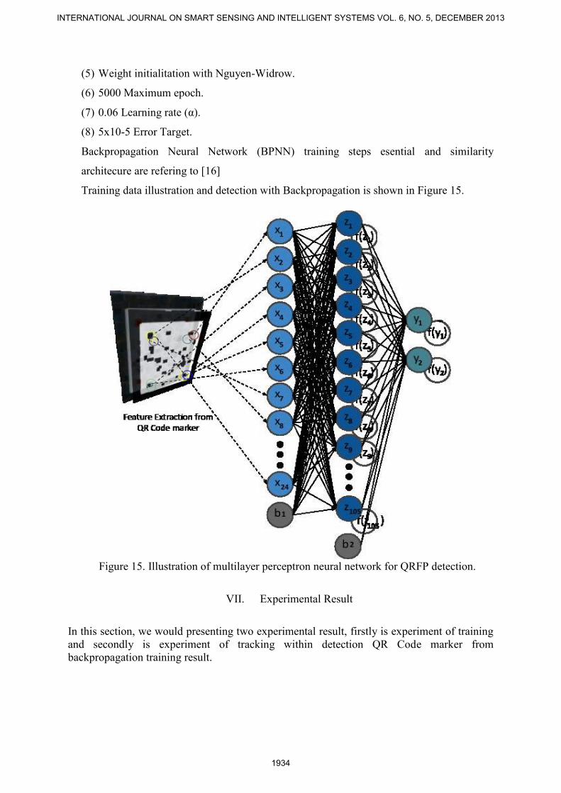
(5) Weight initialitation with Nguyen-Widrow.
(6) 5000 Maximum epoch.
(7) 0.06 Learning rate (α).
(8) 5x10⁻⁵ Error Target.
Backpropagation Neural Network (BPNN) training steps esential and similarity
architecure are refering to [16]
Training data illustration and detection with Backpropagation is shown in Figure 15.
Figure 15. Illustration of multilayer perceptron neural network for QRFP detection.
VII. Experimental Result
In this section, we would presenting two experimental result, firstly is experiment of training
and secondly is experiment of tracking within detection QR Code marker from
backpropagation training result.
INTERNATIONAL JOURNAL ON SMART SENSING AND INTELLIGENT SYSTEMS VOL. 6, NO. 5, DECEMBER 2013
1934
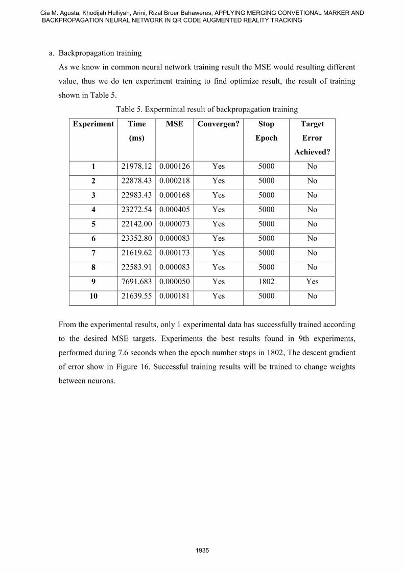
a. Backpropagation training
As we know in common neural network training result the MSE would resulting different
value, thus we do ten experiment training to find optimize result, the result of training
shown in Table 5.
Table 5. Expermintal result of backpropagation training
Experiment Time
(ms)
MSE Convergen? Stop
Epoch
Target
Error
Achieved?
1 21978.12 0.000126 Yes 5000 No
2 22878.43 0.000218 Yes 5000 No
3 22983.43 0.000168 Yes 5000 No
4 23272.54 0.000405 Yes 5000 No
5 22142.00 0.000073 Yes 5000 No
6 23352.80 0.000083 Yes 5000 No
7 21619.62 0.000173 Yes 5000 No
8 22583.91 0.000083 Yes 5000 No
9 7691.683 0.000050 Yes 1802 Yes
10 21639.55 0.000181 Yes 5000 No
From the experimental results, only 1 experimental data has successfully trained according
to the desired MSE targets. Experiments the best results found in 9th experiments,
performed during 7.6 seconds when the epoch number stops in 1802, The descent gradient
of error show in Figure 16. Successful training results will be trained to change weights
between neurons.
Gia M. Agusta, Khodijah Hulliyah, Arini, Rizal Broer Bahaweres, APPLYING MERGING CONVETIONAL MARKER AND BACKPROPAGATION NEURAL NETWORK IN QR CODE AUGMENTED REALITY TRACKING
1935
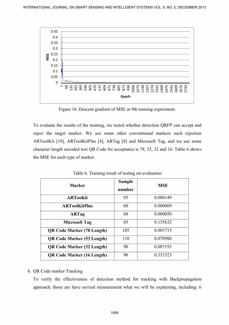
Figure 16. Descent gradient of MSE at 9th training experiment.
To evaluate the results of the training, we tested whether detection QRFP can accept and
reject the target marker. We use some other conventional markers such rejection
ARToolKit [10], ARToolKitPlus [4], ARTag [8] and Microsoft Tag, and we use some
character length encoded text QR Code for acceptance is 78, 53, 32 and 16. Table 6 shows
the MSE for each type of marker.
Table 6. Training result of testing set evaluation
Marker Sample
number MSE
ARTooKit 85 0.000149
ARToolKitPlus 60 0.000069
ARTag 60 0.000050
Microsoft Tag 85 0.155632
QR Code Marker (78 Length) 105 0.003715
QR Code Marker (53 Length) 110 0.070988
QR Code Marker (32 Length) 90 0.087193
QR Code Marker (16 Length) 90 0.351523
b. QR Code marker Tracking
To verify the effectiveness of detection method for tracking with Backpropagation
approach, those are have several measurement what we will be explaining, including: 6
0
0.05
0.1
0.15
0.2
0.25
0.3
0.35
0.4
0.45
16
81
35
20
22
69
33
64
03
47
05
37
60
46
71
73
88
05
87
29
39
10
06
10
73
11
40
12
07
12
74
13
41
14
08
14
75
15
42
16
09
16
76
17
43
MSE
Epoch
INTERNATIONAL JOURNAL ON SMART SENSING AND INTELLIGENT SYSTEMS VOL. 6, NO. 5, DECEMBER 2013
1936
DOF accuration of pitching, yawing and surging; computational speed, and; marker
stability. We have tried to implementing out approach method with 3GHz AMD Athlon II
X2 CPU and the image resolution used for experiment was 640x480.
To observe the required accuracy 6DOF we do observations through decomposition euler
angle (rotation) and translation based on camera model, euler angle and translation are 3x4
matrices obtained through pose estimation, the matrix can be called also extrinsic camera
parameters. Refer to [17] extrinsic parameter can be presented with augmenting translation
in matrix in equation (2).
(2)
Where are the euler angles, cos and sin denote the cosine and sine function, and
three general euler angles can be solved by a little complex formula but translation
augmentation matrix don’t need any formula to solve.
pose estimation is the process after the detection parameter marker with angular
coordinates (corner) at the candidate marker, so all the candidates would pass the marker
is detected pose estimation process.
After going all the candidate marker through pose estimation by the detection process
QRFP with Backpropagation, a prediction target of generating at least one variable is less
than 1.1 and greater than 0.9 and the target variable 2 is less than 0.1 and greater than -0.1
(can be seen in equation (3)), then if the data can be predicted by the value range markers
and after going through the pose estimation can be followed by tracking the augmentation
of 3D objects.
(3)
To determine the maximum degree of 6DOF, we do 6DOF pose tracking which continues
to perform with maximum rotational and translational observe decomposition matrix of
euler angle to happen detectable marker tracking lost [18]. Table 7, 8 and 9 shown the
observation of 6DOF pose tracking.
Gia M. Agusta, Khodijah Hulliyah, Arini, Rizal Broer Bahaweres, APPLYING MERGING CONVETIONAL MARKER AND BACKPROPAGATION NEURAL NETWORK IN QR CODE AUGMENTED REALITY TRACKING
1937
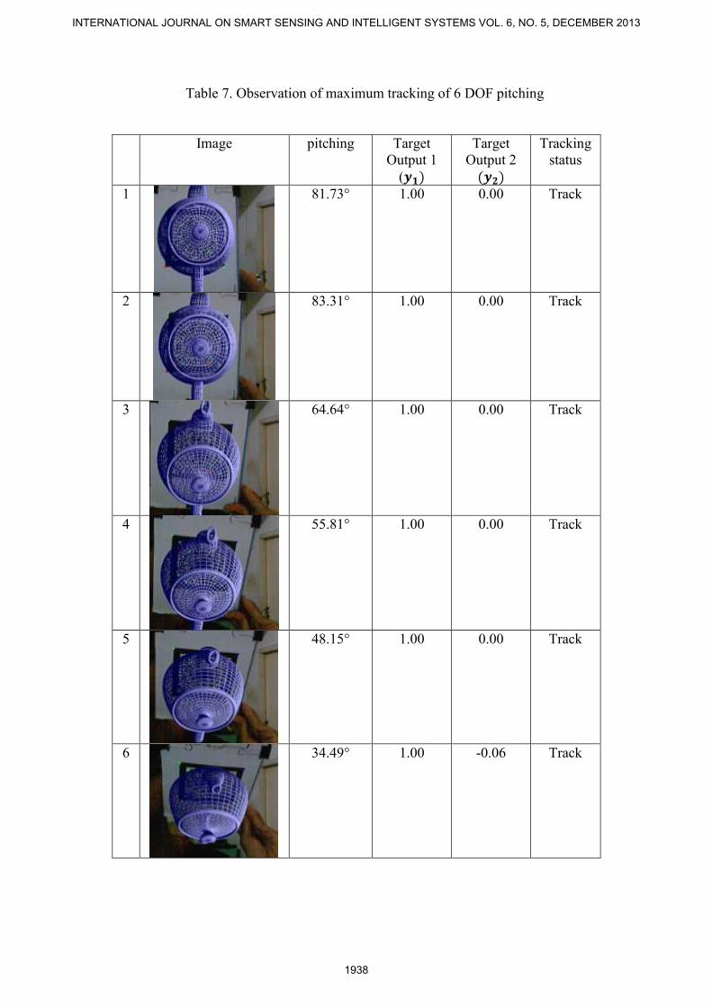
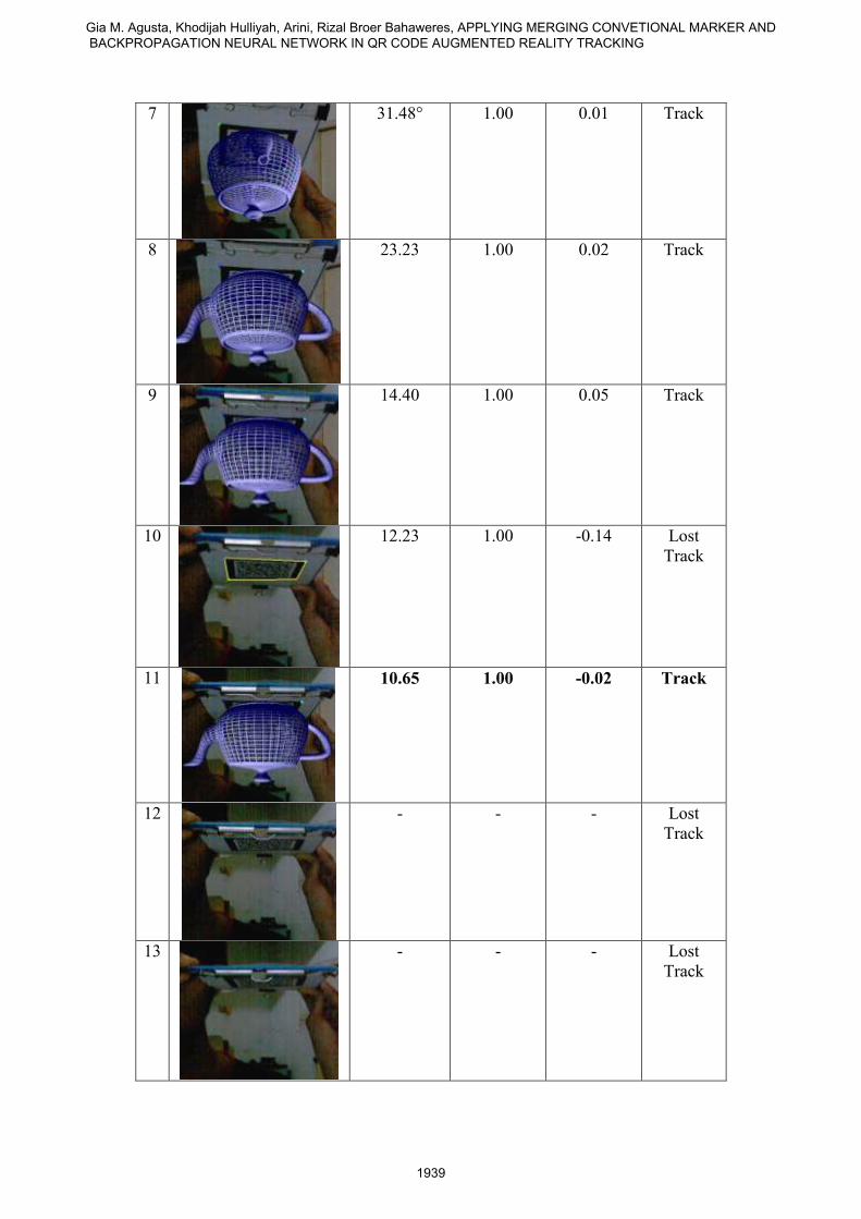
Table 7. Observation of maximum tracking of 6 DOF pitching
Image pitching Target
Output 1
(
Target
Output 2
Tracking
status
1
81.73° 1.00 0.00 Track
2
83.31° 1.00 0.00 Track
3
64.64° 1.00 0.00 Track
4
55.81° 1.00 0.00 Track
5
48.15° 1.00 0.00 Track
6
34.49° 1.00 -0.06 Track
INTERNATIONAL JOURNAL ON SMART SENSING AND INTELLIGENT SYSTEMS VOL. 6, NO. 5, DECEMBER 2013
1938
7
31.48° 1.00 0.01 Track
8
23.23 1.00 0.02 Track
9
14.40 1.00 0.05 Track
10
12.23 1.00 -0.14 Lost
Track
11
10.65 1.00 -0.02 Track
12
- - - Lost
Track
13
- - - Lost
Track
Gia M. Agusta, Khodijah Hulliyah, Arini, Rizal Broer Bahaweres, APPLYING MERGING CONVETIONAL MARKER AND BACKPROPAGATION NEURAL NETWORK IN QR CODE AUGMENTED REALITY TRACKING
1939
14
- - - Lost
Track
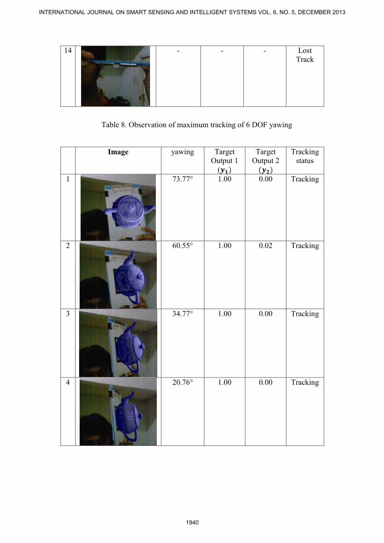
Table 8. Observation of maximum tracking of 6 DOF yawing
Image yawing Target
Output 1
(
Target
Output 2
Tracking
status
1
73.77° 1.00 0.00 Tracking
2
60.55° 1.00 0.02 Tracking
3
34.77° 1.00 0.00 Tracking
4
20.76° 1.00 0.00 Tracking
INTERNATIONAL JOURNAL ON SMART SENSING AND INTELLIGENT SYSTEMS VOL. 6, NO. 5, DECEMBER 2013
1940
5
15.03° 1.00 0.02 Tracking
6
- - - Lost
Track
7
- - - Lost
Track
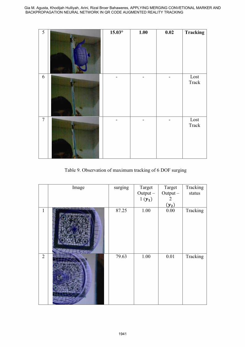
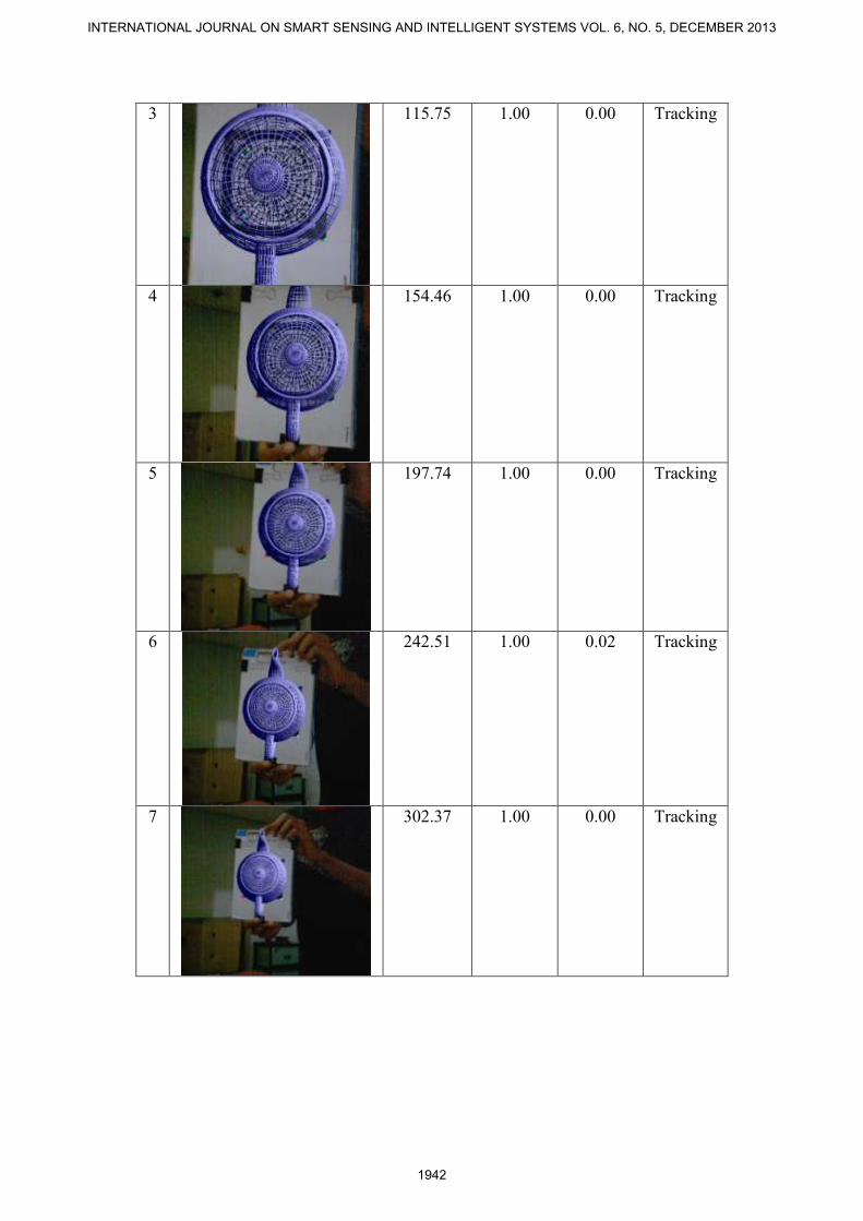
Table 9. Observation of maximum tracking of 6 DOF surging
Image surging Target
Output –
1 (
Target
Output –
2
Tracking
status
1
87.25 1.00 0.00 Tracking
2
79.63 1.00 0.01 Tracking
Gia M. Agusta, Khodijah Hulliyah, Arini, Rizal Broer Bahaweres, APPLYING MERGING CONVETIONAL MARKER AND BACKPROPAGATION NEURAL NETWORK IN QR CODE AUGMENTED REALITY TRACKING
1941
3
115.75 1.00 0.00 Tracking
4
154.46 1.00 0.00 Tracking
5
197.74 1.00 0.00 Tracking
6
242.51 1.00 0.02 Tracking
7
302.37 1.00 0.00 Tracking
INTERNATIONAL JOURNAL ON SMART SENSING AND INTELLIGENT SYSTEMS VOL. 6, NO. 5, DECEMBER 2013
1942
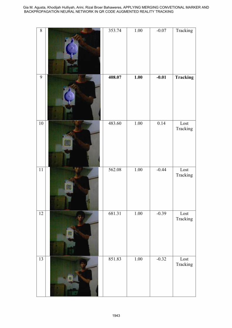
8
353.74 1.00 -0.07 Tracking
9
408.07 1.00 -0.01 Tracking
10
483.60 1.00 0.14 Lost
Tracking
11
562.08 1.00 -0.44 Lost
Tracking
12
681.31 1.00 -0.39 Lost
Tracking
13
851.83 1.00 -0.32 Lost
Tracking
Gia M. Agusta, Khodijah Hulliyah, Arini, Rizal Broer Bahaweres, APPLYING MERGING CONVETIONAL MARKER AND BACKPROPAGATION NEURAL NETWORK IN QR CODE AUGMENTED REALITY TRACKING
1943
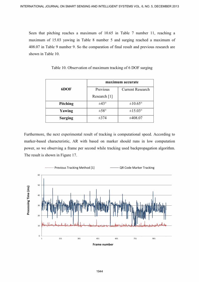
Seen that pitching reaches a maximum of 10.65 in Table 7 number 11, reaching a
maximum of 15.03 yawing in Table 8 number 5 and surging reached a maximum of
408.07 in Table 9 number 9. So the comparation of final result and previous research are
shown in Table 10.
Table 10. Observation of maximum tracking of 6 DOF surging
6DOF
maximum accurate
Previous
Research [1]
Current Research
Pitching ±43° ±10.65°
Yawing ±58° ±15.03°
Surging ±374 ±408.07
Furthermore, the next experimental result of tracking is computational speed. According to
marker-based characteristic, AR with based on marker should runs in low computation
power, so we observing a frame per second while tracking used backpropagation algorithm.
The result is shown in Figure 17.
0
10
20
30
40
50
60
1 151 301 451 601 751 901
Pro
cess
ing
Tim
e (
ms)
Frame number
Previous Tracking Method [1] QR Code Marker Tracking
INTERNATIONAL JOURNAL ON SMART SENSING AND INTELLIGENT SYSTEMS VOL. 6, NO. 5, DECEMBER 2013
1944
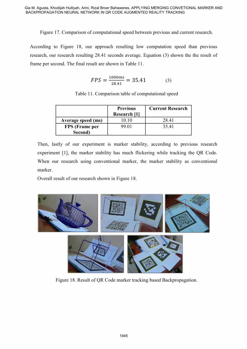
Figure 17. Comparison of computational speed between previous and current research.
According to Figure 18, our approach resulting low computation speed than previous
research, our research resulting 28.41 seconds average. Equation (3) shown the the result of
frame per second. The final result are shown in Table 11.
(3)
Table 11. Comparison table of computational speed
Previous
Research [1]
Current Research
Average speed (ms) 10.10 28.41
FPS (Frame per
Second)
99.01 35.41
Then, lastly of our experiment is marker stability, according to previous research
experiment [1], the marker stability has much flickering while tracking the QR Code.
When our research using conventional marker, the marker stability as conventional
marker.
Overall result of our research shown in Figure 18.
Figure 18. Result of QR Code marker tracking based Backpropagation.
Gia M. Agusta, Khodijah Hulliyah, Arini, Rizal Broer Bahaweres, APPLYING MERGING CONVETIONAL MARKER AND BACKPROPAGATION NEURAL NETWORK IN QR CODE AUGMENTED REALITY TRACKING
1945
VIII. Conclusion and Future Work
Then, lastly of our experiment is marker stability, according to previous research experiment
[1], the marker stability has much flickering while tracking the QR Code. When our research
using conventional marker, the marker stability as conventional marker.
Based on these results, it can be concluded as follows:
(1) Marker merging QR Code with a maximum data retrieval with pitching, yawing and
surging, can achieve an accuracy of ± 6DOF pose tracking of 10.65 º ± 43 º for pitching,
15.03º ± of ± 53° to ± 408.07 Yawing and from ± 374 to surging. Accuracy 6DOF
increase compared with the previous research, thus merging with conventional have good
pose and is good enough to be called “reality”
(2) By applying BPNN, while tracking the speed of the process per frame lag compared to
previous methods, the average speed of the process reached 28.41 milliseconds per
frame, the tracking is done by speed 35.41 fps compared by previous study at 99.01 fps,
thus have enough speed for fps requirement in virtual reality or augmented reality.
(3) By applying merging traditional marker with QR Code Tracking can be more easily
classified without having to go through complicated mechanisms to determining three
QRFP in previous research, the points on the border corner extraction becomes more
stable, stable as conventional marker.
(4) BPNN can only do a maximum of 6DOF pose tracking QR Code with length character
encoding sebsar 78, 53 and 32 while the 16 characters in length often lost tracking.
(5) Sometimes the target marker does not match the output of ANN training although output
has reached the target training. Often lost tracking occurs when too much light and still
need to manually setting thresholds on ARToolKit marker detection algorithm, it is
because the MSE is still quite high when testing.
Some suggestions are put forward for the development of this research are as follows:
(1) There needs to be integration with Kalman Filter [2] method to decode the QR Code as
part of the research data content damage and just focus on the detection QRFP the
required data content error handling.
(2) Need to use PCA [20] method to reduce the input vector to the input variables in order to
predict the output faster output.
(3) Feature selection needs to be done to the image of the QR Code is more accurate and the
use of Support Vector Machine [21] or other methods to solve the problem of over-fitting
and more accurate classification so that no tracking lost.
INTERNATIONAL JOURNAL ON SMART SENSING AND INTELLIGENT SYSTEMS VOL. 6, NO. 5, DECEMBER 2013
1946
REFERENCES
[1] T.-W Kan, C.-H Teng, W.-S Chou, Applying QR Code in Augmented Reality
Applications, Virtual Reality Continuum and its applications in industry, pp. 253 – 257,
2009
[2] J.-T Wang, C.-N Shyi, T.-W. Hou, C.P. Fong, Design and Implementation of
Augmented Reality System Collaborating with QR Code, International Computer
Symposium (ICS), pp. 414 – 418, 2010
[3] S. Siltanen, Theory and applications of marker-based augmented reality. Finland: VTT,
2012.
[4] D. Wagner, D. Schmalstieg, ARToolKitPlus for Pose Tracking on Mobile Devices,
Computer Vision Winter Workshop, 2007
[5] N. Park, W. Lee, W. Woo, Barcode-Assisted Planar Object Tracking Method for
Mobile Augmented Reality, International Symposium on Ubquitous Virtual Reality,
pp. 40 – 43, 2011
[6] K. D. Srinivasa, A. R. Settpalli. Hand Written Charater Recognition using
Backpropagation, Journal of Theoretical and Applied Information Technology (JATIT),
pp. 257-269. 2005
[7] C. Bishop. Neural Networks : A Pattern Recognition Perspective, Birmingham: Neural
Computing Research Group Aston University, 1996
[8] M. Fiala, A Fiducial Marker System Using Digital Techniques, National Research
Council of Canada, 2004
[9] M. Fiala, Webtag: A World Wide Internet Based AR System, Proceedings of the 6th
IEEE/ACM International Symposium on Mixed and Augmented Reality (ISMAR), 2007
[10] H. Kato, M. Billinghurst, Marker Tracking and HMD Calibration for Video-Based
Augmented Reality Conferencing System, 2nd IEEE and ACM International Workshop
on Augmented Reality, iwar, pp.85, 1999
[11] Gia M. Agusta, Khodijah Hulliyah, Arini, Rizal Broer Bahaweres, QR Code
Augmented Reality with Merging on Conventional Marker based Backpropagation
Neural Network, International Advanced Computer Science and Information System
(ICACSIS), pp. 257 – 261, 2012
[12] D. H. Douglas, T.K. Peucker, Algorithms for the Reduction of the Number of Points
Required to Represent a Digitized Line or Its Caricature, Cartographica: The
International Journal for Geographic Information and Geovisualization, pp. 112 –
122, 1973.
[13] Sugiyono. Research Method of Quantitative, Qualitative and R&D. Bandung: Alfabeta,
2006
[14] D. E. Rumelhart, G.E. Hinton, R.J. Williams, Learning representations by back-
propagation errors, Nature 323, pp. 533 – 536, 1986
[15] J. Mustakini. Research Methodology, Yogya: ANDI, 2008
[16] Wu Hongbing, Lou Peihuang, Tang Dunbing, Adaptive Dynamic Clone Selection
Neural Network Algorithm for Motor Fault Diagnosis, Int. Journal Smart Sensing and
Intelligent System, vol. 6, no. 2, pp. 482 – 504, 2013
[17] Zheng Li, Neural Network based multisensor fusion in a novel permanent multi-dof
actuator orientation detection system, Int. Journal Smart Sensing and Intelligent
System, vol. 5, no. 4, pp. 911 – 927, 2012
Gia M. Agusta, Khodijah Hulliyah, Arini, Rizal Broer Bahaweres, APPLYING MERGING CONVETIONAL MARKER AND BACKPROPAGATION NEURAL NETWORK IN QR CODE AUGMENTED REALITY TRACKING
1947
[18] C. Castro, P. Figueroa, A 6 DOF Tracker for Mixed Reality Applications based on AR-
Toolkit, Available: http://imagine.uniandes.edu.co
[19] I. Tetko, D. Livingstone, A. Luik. Neural network studies. Comparison of overfitting
and overtraining, pp. 826 – 833, 1995
[20] H. Abi, L. J. Williams, Principal component analysis, Wiley Interdisciplinary Reviews:
Computational Statistics, pp. 433 – 459, 2010
[21] C. Cortes, V. N. Vapnik, Support-Vector Networks, Machine Learning, 1995
INTERNATIONAL JOURNAL ON SMART SENSING AND INTELLIGENT SYSTEMS VOL. 6, NO. 5, DECEMBER 2013
1948