Embed Size (px)
Citation preview
Applied co-simulation of intelligent power
systems: implementation, usage, examplesPeter Palensky, Senior Member, IEEE, IES, Arjen A. van der Meer, Member, IEEE, IES, Claudio David
Lopez, Member, IEEE, Arun Joseph, Student Member, IEEE, IES, Kaikai Pan, Student Member, IEEE
Abstract
Smart Grids link various types of energy technologies such as power electronics, machines, grids, and markets
via communication technology, which leads to trans-disciplinary, multi-domain system. Simulation packages for
assessing system integration of components typically cover only one sub-domain, while terribly simplifying the
others. Co-simulation overcomes this by coupling sub-domain models that are described and solved within their
native environments, using specialized solvers and validated libraries. This article discusses the state of the art and
conceptually describes the main challenges for simulating intelligent power systems. Part 1 covers fundamental
concepts, part 2 applications.
Index Terms
smart grids, co-simulation, power system simulation, HIL, intelligent electrical power system, VSC-HVDC, ICT
I. INTRODUCTION
Recent developments in information and communication technology (ICT) architectures, the massive installation
of distributed energy resources (DER), and the emergence of demand-side energy management instruments have lead
to a rapid deployment of smart grids [1], [2]. The corresponding coupling of power grids with various other systems,
which on occasion can be of an entirely different nature, opens a wide range of mutual interaction opportunities, for
example, energy storage options in gas or heat networks. The merits of the evolution towards intelligent electrical
power systems are evident: the higher controllability of the electric power system potentially fosters its reliability,
general operability, and benefits the electricity market.
The operating service of power system assets commonly spans several decades. A specific challenge here is the
rapid development cycle of ICT and power electronic devices: the behavior of the individual subsystems as well as
their interaction with each other will change quickly over time, whereas it is also manifest to carefully address the
integral system behavior over the assets’ life span in planning studies performed today. It is therefore significant
to set out scenarios, testing schemes, and sophisticated simulation platforms to take up this challenge [3].
The present behaviour of the power system still relies to a large extent on physical quantities such as the elec-
tromechanical and electromagnetic interactions of rotating machines, lines, converters, smart meters, etc. Studying
behavior is generally speaking conducted on offline workstations in the time-domain by simulation experiments,
and thereby using continuous modeling of components. Large systems that need to be simulated in high detail do
usually not fit well into this approach. This gives rise to splitting the overall model into parts that are individually
February 16, 2017 DRAFT
IEEE INDUSTRIAL ELECTRONICS MAGAZINE 1
considered on separate processes that operate in parallel. Such distributed models are common practice for (real-
time) electromagnetic transients (EMT) simulation.
Modern power systems contain also subsystems of very different nature for which continuous simulators are
unsuitable. Computer networks and communication structures that fulfill dedicated control purposes have a discrete,
event-driven nature, and show stochastically distributed latencies. As a matter of fact, some of these controls rely on
automatic functionality based on heuristics, regulation (e.g., electricity markets, grid code compliance), or combined
with human supervision. Such multi-domain systems do not fit very well into the current (monolithic) power system
and components simulation paradigms.
The algorithms of single domain simulators have usually been developed and numerically optimized over decades,
and extending such solvers to multi-domain functionality commonly compromises on the numerical behaviour (solver
speed, accuracy), as discussed in part I of this article. It is therefore time to move towards simulation platforms
that can handle multi-domain systems with reasonable detail and simulation speed. Coupled simulations or co-
simulations aim to fulfill these needs by modeling multi-domain systems across multiple simulation tools, while
acting as one integral simulation platform that addresses the study [4].
Until present, co-simulation (sometimes also referred to as combined simulation or co-operative simulation) in
the power system domain has been mainly reported for single domain, distributed-model problems. Among these
are real-time EMT simulation of smart grids [5], hybrid (SPICE-type) circuit–EMT–stability simulations [6], and
parallelised EMT simulations on workstations [7], [8]. These approaches, however, did not implement the overall
system as distributed models into separate simulation processes. In [5], for instance, a smart grid test setup was
simulated in real-time. This is a multi-domain system under test being solved inside a particular fixed model
framework, i.e., an electrotechnical (monolithic) continuous simulation. Pure co-simulation separates the models
and the various solvers, and focuses on the coupling between the processes. Particularly for smart grids such a
distributed approach would be of great advantage as distributed systems of arbitrary nature are interconnected via
ICT or physical links.
Above considerations for co-simulation require the integration of simulation tools for intelligent electrical power
systems beyond the state-of-the-art. No fully fledged alternative assessment method is available: experiments
are expensive, time consuming, and are often restricted by the laboratory facilities. Especially for intelligent
electrical trans-disciplinary power systems this is challenging. Monolithic multi-domain simulators on their turn
allow assessing such systems at the cost of system scalability and sub-optimal numerical algorithms [9]. This gives
rise to various challenges for co-simulations such as:
• Refined simulation and system testing and validation procedures (e.g., success parameters);
• Hardware-in-the-loop treatment (e.g., controller and amplifier interface standardization, harmonized data struc-
tures, master algorithm compatibility);
• Dedicated coupling and model library development (e.g., harmonization of models);
• Fostering applicability by standardization of interfacing techniques among the various tools involved; and
• Model and simulation coupling algorithms (i.e., numerical algorithms).
These challenges signify the need for a clear positioning of various aspects and implications of co-simulation in
February 16, 2017 DRAFT
IEEE INDUSTRIAL ELECTRONICS MAGAZINE 2
terms of power system assessment. The second part of the article on simulation of intelligent power systems covers
the application of co-simulation to test cases that span various domains. This paper thereby mainly confines itself to
systems that represent a hardware infrastructure, such as ICT and power engineering systems. Stochastic systems,
big-data issues, and rule-based actors, which add an entirely different meta-level dimension to the heterogeneity
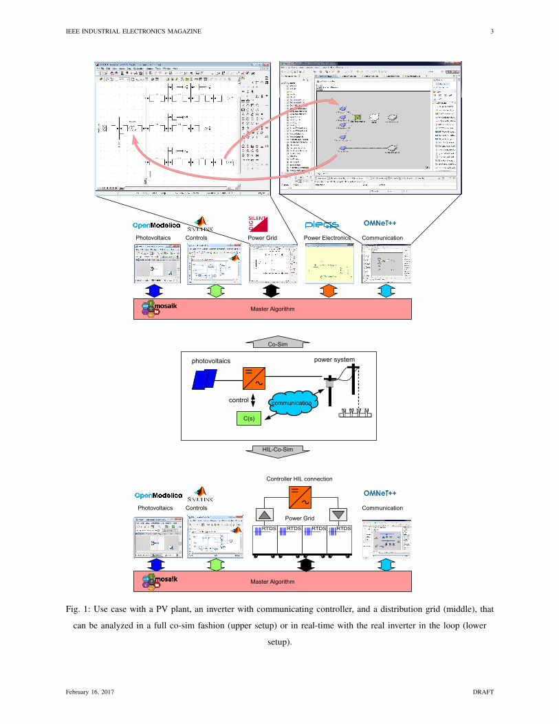
challenge [10], [11], are outside the application scope of the paper. Figure 1 shows for instance a system under
test inside the distribution system. It consists of a photo-voltaic plant grid-connected to the distribution network
by a three-phase inverter. In a smart grid the control system is typically part of a larger, centralized control entity
that provides high-level quantities such as voltage and power setpoint through telecommunication. For ensuring the
interoperability of the PV plant at the coupling point, a series of experiments need to be undergone. Defining the
actual test setup for assessing these test criteria is a challenge. Non-virtual (hardware) experiments, e.g., testing
the PV plant in a laboratory, would impel the control part of the system under test to be significantly reduced or
disregarded at all. Virtual (software) experiments, on the other hand, need an extensive model library of physical and
discrete components, which need to be solved in a monolithic fashion. Co-simulations allow virtual and non-virtual
experiments to be combined by interfacing refined domain-specific tools, or even go one step further and attach real
controllers or power hardware-in-the-loop. Figure 1 shows how a typical co-simulation test setup can be achieved
to accurately handle the higher-level controls for this particular test case.
February 16, 2017 DRAFT
IEEE INDUSTRIAL ELECTRONICS MAGAZINE 3
Fig. 1: Use case with a PV plant, an inverter with communicating controller, and a distribution grid (middle), that
can be analyzed in a full co-sim fashion (upper setup) or in real-time with the real inverter in the loop (lower
setup).
February 16, 2017 DRAFT
IEEE INDUSTRIAL ELECTRONICS MAGAZINE 4
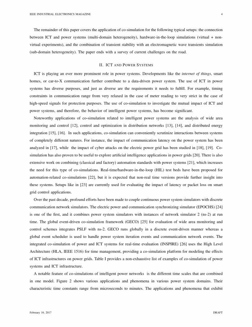
The remainder of this paper covers the application of co-simulation for the following typical setups: the connection
between ICT and power systems (multi-domain heterogeneity), hardware-in-the-loop simulations (virtual + non-
virtual experiments), and the combination of transient stability with an electromagnetic wave transients simulation
(sub-domain heterogeneity). The paper ends with a survey of current challenges on the road.
II. ICT AND POWER SYSTEMS
ICT is playing an ever more prominent role in power systems. Developments like the internet of things, smart
homes, or car-to-X communication further contribute to a data-driven power system. The use of ICT in power
systems has diverse purposes, and just as diverse are the requirements it needs to fulfill. For example, timing
constraints in communication range from very relaxed in the case of meter reading to very strict in the case of
high-speed signals for protection purposes. The use of co-simulation to investigate the mutual impact of ICT and
power systems, and therefore, the behavior of intelligent power systems, has become significant.
Noteworthy applications of co-simulation related to intelligent power systems are the analysis of wide area
monitoring and control [12], control and optimization in distribution networks [13], [14], and distributed energy
integration [15], [16]. In such applications, co-simulation can conveniently scrutinize interactions between systems
of completely different natures. For instance, the impact of communication latency on the power system has been
analyzed in [17], while the impact of cyber attacks on the electric power grid has been studied in [18], [19]. Co-
simulation has also proven to be useful to explore artificial intelligence applications in power grids [20]. There is also
extensive work on combining (classical and factory) automation standards with power systems [21], which increases
the need for this type of co-simulations. Real-time/hardware-in-the-loop (HIL) test beds have been proposed for
automation-related co-simulations [22], but it is expected that non-real time versions provide further insight into
these systems. Setups like in [23] are currently used for evaluating the impact of latency or packet loss on smart
grid control applications.
Over the past decade, profound efforts have been made to couple continuous power system simulators with discrete
communication network simulators. The electric power and communication synchronizing simulator (EPOCHS) [24]
is one of the first, and it combines power system simulators with instances of network simulator 2 (ns-2) at run
time. The global event-driven co-simulation framework (GECO) [25] for evaluation of wide area monitoring and
control schemes integrates PSLF with ns-2. GECO runs globally in a discrete event-driven manner whereas a
global event scheduler is used to handle power system iteration events and communication network events. The
integrated co-simulation of power and ICT systems for real-time evaluation (INSPIRE) [26] uses the High Level
Architecture (HLA, IEEE 1516) for time management, providing a co-simulation platform for modeling the effects
of ICT infrastructures on power grids. Table I provides a non-exhaustive list of examples of co-simulation of power
systems and ICT infrastructure.
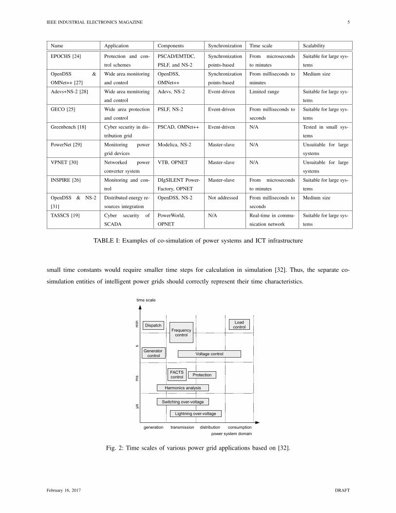
A notable feature of co-simulations of intelligent power networks is the different time scales that are combined
in one model. Figure 2 shows various applications and phenomena in various power system domains. Their
characteristic time constants range from microseconds to minutes. The applications and phenomena that exhibit
February 16, 2017 DRAFT
IEEE INDUSTRIAL ELECTRONICS MAGAZINE 5
Name Application Components Synchronization Time scale Scalability
EPOCHS [24] Protection and con-
trol schemes
PSCAD/EMTDC,
PSLF, and NS-2
Synchronization
points-based
From microseconds
to minutes
Suitable for large sys-
tems
OpenDSS &
OMNet++ [27]
Wide area monitoring
and control
OpenDSS,
OMNet++
Synchronization
points-based
From milliseconds to
minutes
Medium size
Adevs+NS-2 [28] Wide area monitoring
and control
Adevs, NS-2 Event-driven Limited range Suitable for large sys-
tems
GECO [25] Wide area protection
and control
PSLF, NS-2 Event-driven From milliseconds to
seconds
Suitable for large sys-
tems
Greenbench [18] Cyber security in dis-
tribution grid
PSCAD, OMNet++ Event-driven N/A Tested in small sys-
tems
PowerNet [29] Monitoring power
grid devices
Modelica, NS-2 Master-slave N/A Unsuitable for large
systems
VPNET [30] Networked power
converter system
VTB, OPNET Master-slave N/A Unsuitable for large
systems
INSPIRE [26] Monitoring and con-
trol
DIgSILENT Power-
Factory, OPNET
Master-slave From microseconds
to minutes
Suitable for large sys-
tems
OpenDSS & NS-2
[31]
Distributed energy re-
sources integration
OpenDSS, NS-2 Not addressed From milliseconds to
seconds
Medium size
TASSCS [19] Cyber security of
SCADA
PowerWorld,
OPNET
N/A Real-time in commu-
nication network
Suitable for large sys-
tems
TABLE I: Examples of co-simulation of power systems and ICT infrastructure
small time constants would require smaller time steps for calculation in simulation [32]. Thus, the separate co-
simulation entities of intelligent power grids should correctly represent their time characteristics.
Fig. 2: Time scales of various power grid applications based on [32].
February 16, 2017 DRAFT
IEEE INDUSTRIAL ELECTRONICS MAGAZINE 6
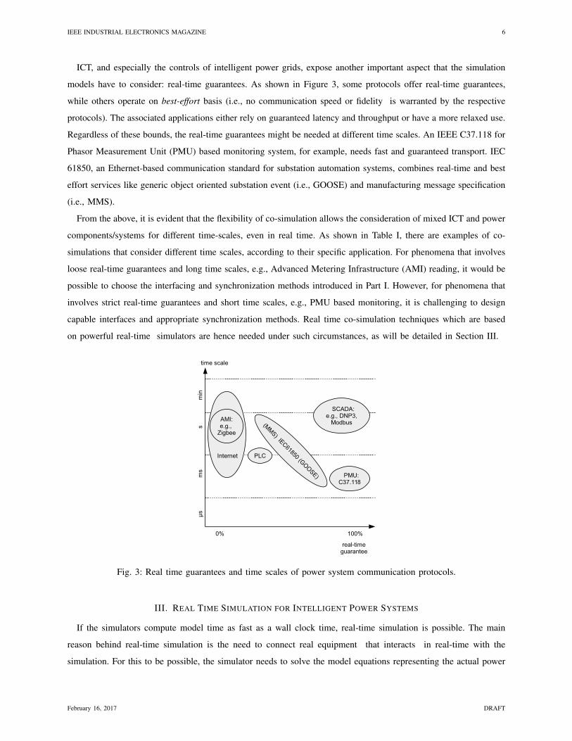
ICT, and especially the controls of intelligent power grids, expose another important aspect that the simulation
models have to consider: real-time guarantees. As shown in Figure 3, some protocols offer real-time guarantees,
while others operate on best-effort basis (i.e., no communication speed or fidelity is warranted by the respective
protocols). The associated applications either rely on guaranteed latency and throughput or have a more relaxed use.
Regardless of these bounds, the real-time guarantees might be needed at different time scales. An IEEE C37.118 for
Phasor Measurement Unit (PMU) based monitoring system, for example, needs fast and guaranteed transport. IEC
61850, an Ethernet-based communication standard for substation automation systems, combines real-time and best
effort services like generic object oriented substation event (i.e., GOOSE) and manufacturing message specification
(i.e., MMS).
From the above, it is evident that the flexibility of co-simulation allows the consideration of mixed ICT and power
components/systems for different time-scales, even in real time. As shown in Table I, there are examples of co-
simulations that consider different time scales, according to their specific application. For phenomena that involves
loose real-time guarantees and long time scales, e.g., Advanced Metering Infrastructure (AMI) reading, it would be
possible to choose the interfacing and synchronization methods introduced in Part I. However, for phenomena that
involves strict real-time guarantees and short time scales, e.g., PMU based monitoring, it is challenging to design
capable interfaces and appropriate synchronization methods. Real time co-simulation techniques which are based
on powerful real-time simulators are hence needed under such circumstances, as will be detailed in Section III.
Fig. 3: Real time guarantees and time scales of power system communication protocols.
III. REAL TIME SIMULATION FOR INTELLIGENT POWER SYSTEMS
If the simulators compute model time as fast as a wall clock time, real-time simulation is possible. The main
reason behind real-time simulation is the need to connect real equipment that interacts in real-time with the
simulation. For this to be possible, the simulator needs to solve the model equations representing the actual power
February 16, 2017 DRAFT
IEEE INDUSTRIAL ELECTRONICS MAGAZINE 7
system network, power electronic device, or communication system for one time-step within the same time as in a
real world clock. Real-time simulation applied to the domain of intelligent power systems can be classified in two
categories: fully digital and hardware-in-the-loop real-time simulations. In fully digital real time simulations, the
entire model of the system under analysis is simulated on a dedicated platform with simulation software that can
ensure the fulfillment of real-time constraints. In HIL simulations, a part of the model is replaced by an actual
physical component (e.g., a controller, power electronic device, etc.). Thus, for HIL simulation, a digital real-time
simulator (DRTS) with interfacing capabilities for connecting external devices required.
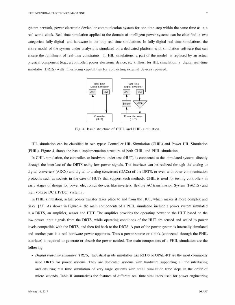
Fig. 4: Basic structure of CHIL and PHIL simulation.
HIL simulation can be classified in two types: Controller HIL Simulation (CHIL) and Power HIL Simulation
(PHIL). Figure 4 shows the basic implementation structure of both CHIL and PHIL simulation.
In CHIL simulation, the controller, or hardware under test (HUT), is connected to the simulated system directly
through the interface of the DRTS using low power signals. The interface can be realized through the analog to
digital converters (ADCs) and digital to analog converters (DACs) of the DRTS, or even with other communication
protocols such as sockets in the case of HUTs that support such methods. CHIL is used for testing controllers in
early stages of design for power electronics devices like inverters, flexible AC transmission System (FACTS) and
high voltage DC (HVDC) systems .
In PHIL simulation, actual power transfer takes place to and from the HUT, which makes it more complex and
risky [33]. As shown in Figure 4, the main components of a PHIL simulation include a power system simulated
in a DRTS, an amplifier, sensor and HUT. The amplifier provides the operating power to the HUT based on the
low-power input signals from the DRTS, while operating conditions of the HUT are sensed and scaled to power
levels compatible with the DRTS, and then fed back to the DRTS. A part of the power system is internally simulated
and another part is a real hardware power apparatus. Thus a power source or a sink (connected through the PHIL
interface) is required to generate or absorb the power needed. The main components of a PHIL simulation are the
following:
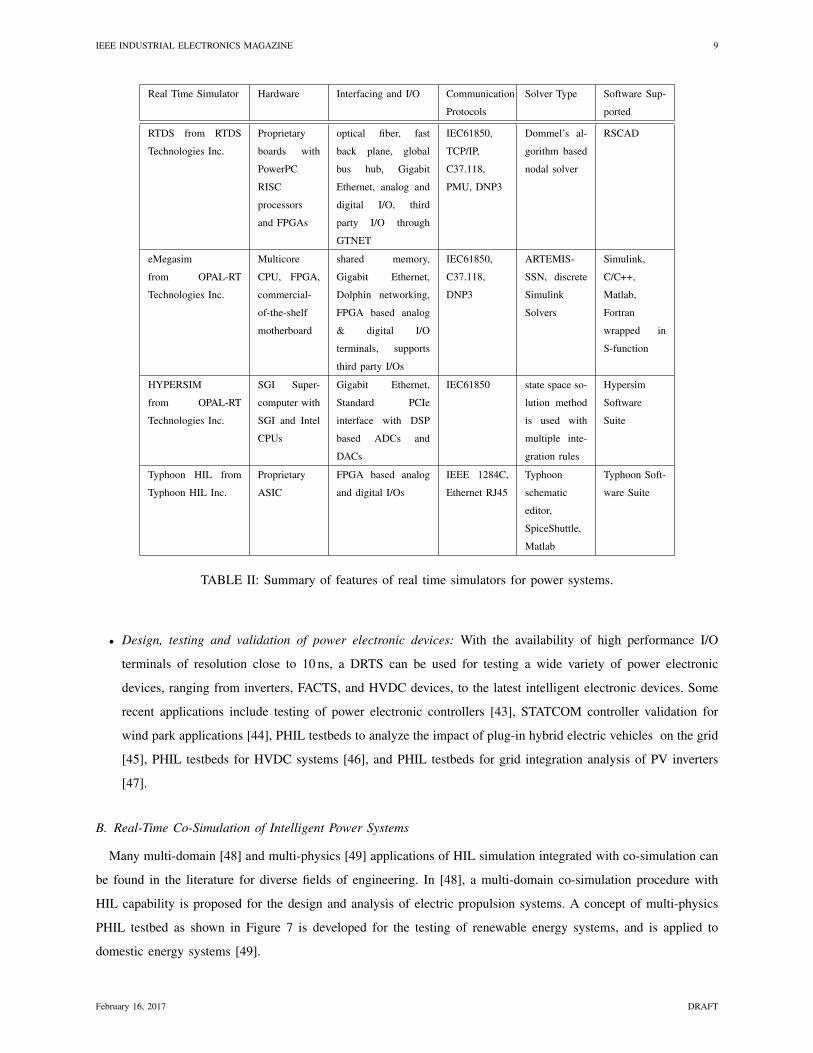
• Digital real-time simulator (DRTS): Industrial grade simulators like RTDS or OPAL-RT are the most commonly
used DRTS for power systems. They are dedicated systems with hardware supporting all the interfacing
and ensuring real time simulation of very large systems with small simulation time steps in the order of
micro seconds. Table II summarizes the features of different real time simulators used for power engineering
February 16, 2017 DRAFT
IEEE INDUSTRIAL ELECTRONICS MAGAZINE 8
applications in terms of interfacing methods used, type of hardware used, communication protocols supported,
solver and simulation software used, etc., according to [34]. The main advantage of such DRTS systems is
that they have libraries with application-specific models that are accepted by the industry.
• Power amplification unit: A power amplifier allows the transfer of power between the HUT and the part of
the power system simulated in the DRTS at the point of common coupling. The selection of such an amplifier
plays a crucial role in the stability and accuracy of PHIL simulation, since these factors are influenced by
parameters like bandwidth, slew-rate and short circuit behavior. [35]. .
• Interface algorithms: Interface algorithms provide the means for relating the voltages and currents on the
DRTS side to the HUT side of the PHIL simulation. They play a critical role in determining accuracy and
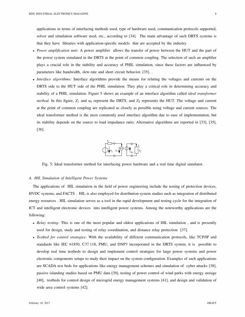
stability of a PHIL simulation. Figure 5 shows an example of an interface algorithm called ideal transformer
method. In this figure, Z1 and u0 represent the DRTS, and Z2 represents the HUT. The voltage and current
at the point of common coupling are replicated as closely as possible using voltage and current sources. The
ideal transformer method is the most commonly used interface algorithm due to ease of implementation, but
its stability depends on the source to load impedance ratio. Alternative algorithms are reported in [33], [35],
[36].
Fig. 5: Ideal transformer method for interfacing power hardware and a real time digital simulator.
A. HIL Simulation of Intelligent Power Systems
The applications of HIL simulation in the field of power engineering include the testing of protection devices,
HVDC systems, and FACTS . HIL is also employed for distribution system studies such as integration of distributed
energy resources . HIL simulation serves as a tool in the rapid development and testing cycle for the integration of
ICT and intelligent electronic devices into intelligent power systems. Among the noteworthy applications are the
following:
• Relay testing: This is one of the most popular and oldest applications of HIL simulation , and is presently
used for design, study and testing of relay coordination, and distance relay protection [37].
• Testbed for control strategies: With the availability of different communication protocols, like TCP/IP and
standards like IEC 61850, C37.118, PMU, and DNP3 incorporated in the DRTS system, it is possible to
develop real time testbeds to design and implement control strategies for large power systems and power
electronic components setups to study their impact on the system configuration. Examples of such applications
are SCADA test beds for applications like energy management schemes and simulation of cyber attacks [38],
passive islanding studies based on PMU data [39], testing of power control of wind parks with energy storage
[40], testbeds for control design of microgrid energy management systems [41], and design and validation of
wide area control systems [42].
February 16, 2017 DRAFT
IEEE INDUSTRIAL ELECTRONICS MAGAZINE 9
Real Time Simulator Hardware Interfacing and I/O Communication
Protocols
Solver Type Software Sup-
ported
RTDS from RTDS
Technologies Inc.
Proprietary
boards with
PowerPC
RISC
processors
and FPGAs
optical fiber, fast
back plane, global
bus hub, Gigabit
Ethernet, analog and
digital I/O, third
party I/O through
GTNET
IEC61850,
TCP/IP,
C37.118,
PMU, DNP3
Dommel’s al-
gorithm based
nodal solver
RSCAD
eMegasim
from OPAL-RT
Technologies Inc.
Multicore
CPU, FPGA,
commercial-
of-the-shelf
motherboard
shared memory,
Gigabit Ethernet,
Dolphin networking,
FPGA based analog
& digital I/O
terminals, supports
third party I/Os
IEC61850,
C37.118,
DNP3
ARTEMIS-
SSN, discrete
Simulink
Solvers
Simulink,
C/C++,
Matlab,
Fortran
wrapped in
S-function
HYPERSIM
from OPAL-RT
Technologies Inc.
SGI Super-
computer with
SGI and Intel
CPUs
Gigabit Ethernet,
Standard PCIe
interface with DSP
based ADCs and
DACs
IEC61850 state space so-
lution method
is used with
multiple inte-
gration rules
Hypersim
Software
Suite
Typhoon HIL from
Typhoon HIL Inc.
Proprietary
ASIC
FPGA based analog
and digital I/Os
IEEE 1284C,
Ethernet RJ45
Typhoon
schematic
editor,
SpiceShuttle,
Matlab
Typhoon Soft-
ware Suite
TABLE II: Summary of features of real time simulators for power systems.
• Design, testing and validation of power electronic devices: With the availability of high performance I/O
terminals of resolution close to 10 ns, a DRTS can be used for testing a wide variety of power electronic
devices, ranging from inverters, FACTS, and HVDC devices, to the latest intelligent electronic devices. Some
recent applications include testing of power electronic controllers [43], STATCOM controller validation for
wind park applications [44], PHIL testbeds to analyze the impact of plug-in hybrid electric vehicles on the grid
[45], PHIL testbeds for HVDC systems [46], and PHIL testbeds for grid integration analysis of PV inverters
[47].
B. Real-Time Co-Simulation of Intelligent Power Systems
Many multi-domain [48] and multi-physics [49] applications of HIL simulation integrated with co-simulation can
be found in the literature for diverse fields of engineering. In [48], a multi-domain co-simulation procedure with
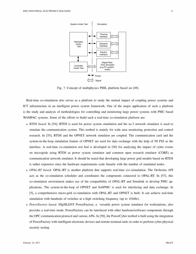
HIL capability is proposed for the design and analysis of electric propulsion systems. A concept of multi-physics
PHIL testbed as shown in Figure 7 is developed for the testing of renewable energy systems, and is applied to
domestic energy systems [49].
February 16, 2017 DRAFT
IEEE INDUSTRIAL ELECTRONICS MAGAZINE 10
Considering the the state-of-the-art of computing, sensing, and communication technologies, it is reasonable to
assume HIL integrated with co-simulation capabilities will become a relevant tool for the study and analysis of
future intelligent power systems. Applications of such HIL co-simulation testbeds include analyzing distribution
grids for demand response strategies [50], and testing of demand side management techniques to provide ancillary
services [51]. In [50] the VirGIL HIL co-simulation testbed is introduced using a master algorithm developed
in Ptolemy II that coordinates the data exchange between all individual components. The communication between
different components is done using the FMI standard. The individual components include PowerFactory as the power
system simulator, OMNeT++ for the communications network simulator, Modelica for the building model/control,
and the Ptolemy II environment for HIL simulation. The real-time PHIL co-simulation testbed introduced in [51]
consist of a demand side management module, real-time simulator module (by Applied Dynamics International)
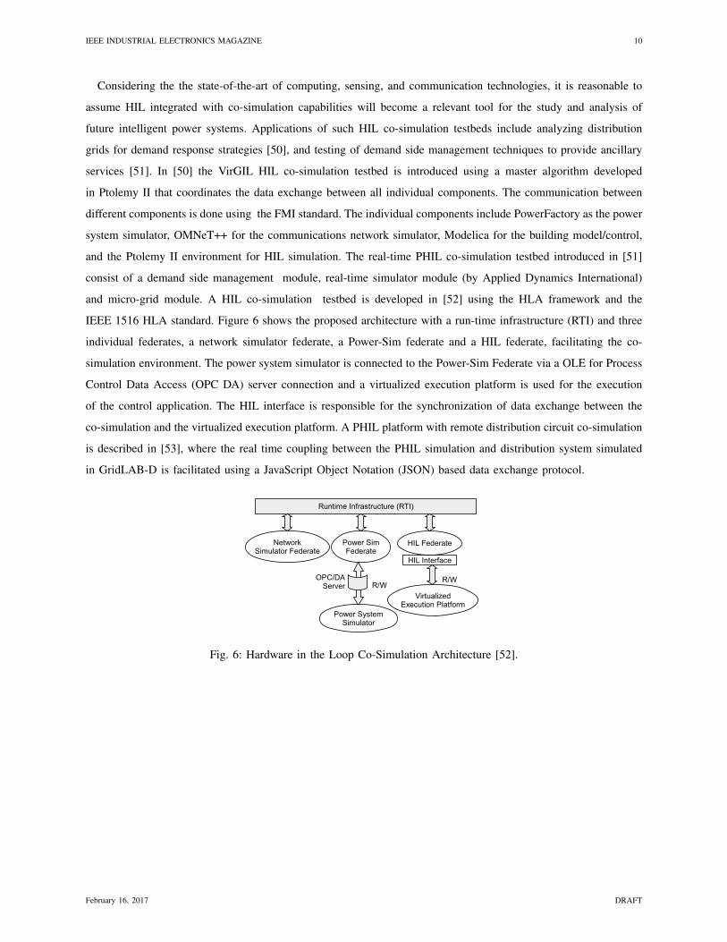
and micro-grid module. A HIL co-simulation testbed is developed in [52] using the HLA framework and the
IEEE 1516 HLA standard. Figure 6 shows the proposed architecture with a run-time infrastructure (RTI) and three
individual federates, a network simulator federate, a Power-Sim federate and a HIL federate, facilitating the co-
simulation environment. The power system simulator is connected to the Power-Sim Federate via a OLE for Process
Control Data Access (OPC DA) server connection and a virtualized execution platform is used for the execution
of the control application. The HIL interface is responsible for the synchronization of data exchange between the
co-simulation and the virtualized execution platform. A PHIL platform with remote distribution circuit co-simulation
is described in [53], where the real time coupling between the PHIL simulation and distribution system simulated
in GridLAB-D is facilitated using a JavaScript Object Notation (JSON) based data exchange protocol.
Fig. 6: Hardware in the Loop Co-Simulation Architecture [52].
February 16, 2017 DRAFT
IEEE INDUSTRIAL ELECTRONICS MAGAZINE 11
Fig. 7: Concept of multiphysics PHIL platform based on [49].
Real-time co-simulation also serves as a platform to study the mutual impact of coupling power systems and
ICT infrastructure in an intelligent power system framework. One of the major application of such a platform
is the study and analysis of methodologies for controlling and monitoring large power systems with PMU based
WAMPAC systems. Some of the efforts to build such a real-time co-simulation platform are:
• RTDS based: In [54], RTDS is used for power system simulation and the ns-3 network simulator is used to
simulate the communication system. This testbed is mainly for wide area monitoring protection and control
research. In [55], RTDS and the OPNET network simulator are coupled. The communication card and the
system-in-the-loop simulation feature of OPNET are used for data exchange with the help of NI PXI as the
interface. A real-time co-simulation test bed is developed in [56] for analyzing the impact of cyber events
on microgrids using RTDS as power system simulator and common open research emulator (CORE) as
communication network emulator. It should be noted that developing large power grid models based on RTDS
is rather expensive since the hardware requirements scale linearly with the number of simulated nodes.
• OPAL-RT based: OPAL-RT is another platform that supports real-time (co-)simulation. The Orchestra API
acts as the co-simulation scheduler and coordinates the components connected to OPAL-RT. In [57], this
co-simulation environment makes use of the compatibility of OPAL-RT and Simulink to develop PMU ap-
plications. The system-in-the-loop of OPNET and SoftPMU is used for interfacing and data exchange. In
[5], a comprehensive micro-grid co-simulation with OPAL-RT and OPNET is built. It can achieve real-time
simulation with hundreds of switches at a high switching frequency (up to 10 kHz).
• PowerFactory based: DIgSILENT PowerFactory, a versatile power system simulator for workstations, also
provides a real-time mode. PowerFactory can be interfaced with other hardware/software components through
the OPC communication protocol and various APIs. In [58], the PowerCyber testbed is built using the integration
of PowerFactory with intelligent electronic devices and remote terminal units in order to perform cyber-physical
security testing.
February 16, 2017 DRAFT
IEEE INDUSTRIAL ELECTRONICS MAGAZINE 12
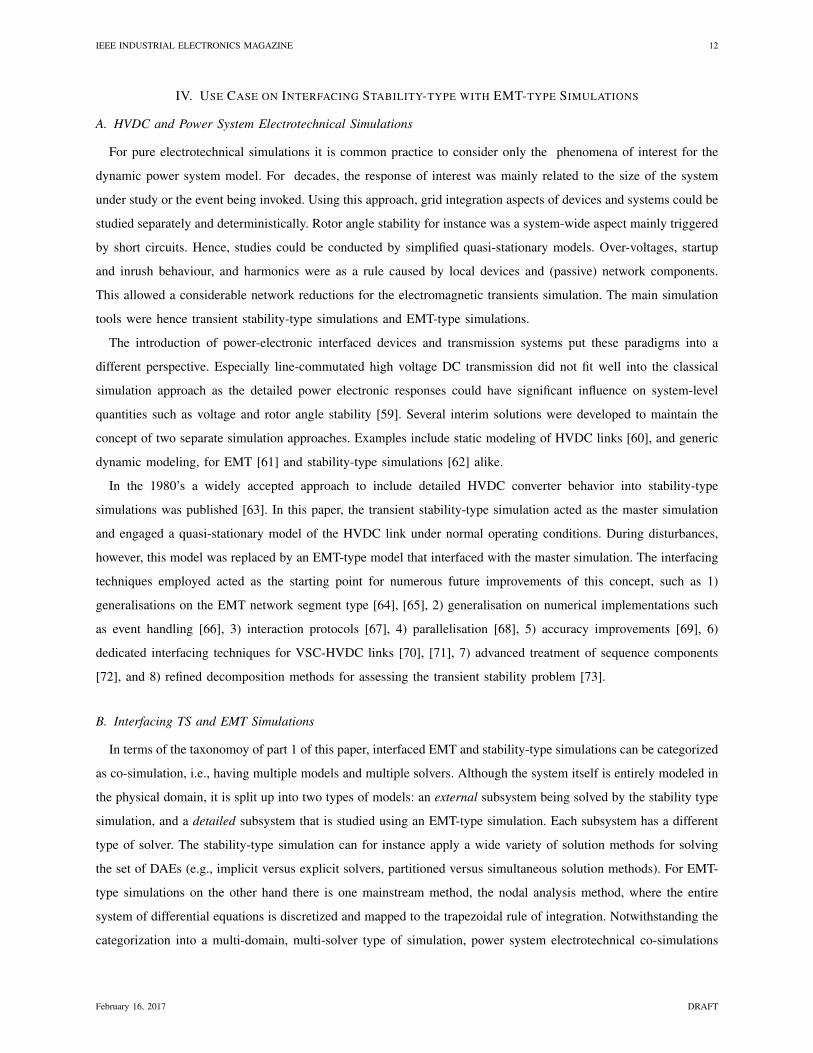
IV. USE CASE ON INTERFACING STABILITY-TYPE WITH EMT-TYPE SIMULATIONS
A. HVDC and Power System Electrotechnical Simulations
For pure electrotechnical simulations it is common practice to consider only the phenomena of interest for the
dynamic power system model. For decades, the response of interest was mainly related to the size of the system
under study or the event being invoked. Using this approach, grid integration aspects of devices and systems could be
studied separately and deterministically. Rotor angle stability for instance was a system-wide aspect mainly triggered
by short circuits. Hence, studies could be conducted by simplified quasi-stationary models. Over-voltages, startup
and inrush behaviour, and harmonics were as a rule caused by local devices and (passive) network components.
This allowed a considerable network reductions for the electromagnetic transients simulation. The main simulation
tools were hence transient stability-type simulations and EMT-type simulations.
The introduction of power-electronic interfaced devices and transmission systems put these paradigms into a
different perspective. Especially line-commutated high voltage DC transmission did not fit well into the classical
simulation approach as the detailed power electronic responses could have significant influence on system-level
quantities such as voltage and rotor angle stability [59]. Several interim solutions were developed to maintain the
concept of two separate simulation approaches. Examples include static modeling of HVDC links [60], and generic
dynamic modeling, for EMT [61] and stability-type simulations [62] alike.
In the 1980’s a widely accepted approach to include detailed HVDC converter behavior into stability-type
simulations was published [63]. In this paper, the transient stability-type simulation acted as the master simulation
and engaged a quasi-stationary model of the HVDC link under normal operating conditions. During disturbances,
however, this model was replaced by an EMT-type model that interfaced with the master simulation. The interfacing
techniques employed acted as the starting point for numerous future improvements of this concept, such as 1)
generalisations on the EMT network segment type [64], [65], 2) generalisation on numerical implementations such
as event handling [66], 3) interaction protocols [67], 4) parallelisation [68], 5) accuracy improvements [69], 6)
dedicated interfacing techniques for VSC-HVDC links [70], [71], 7) advanced treatment of sequence components
[72], and 8) refined decomposition methods for assessing the transient stability problem [73].
B. Interfacing TS and EMT Simulations
In terms of the taxonomoy of part 1 of this paper, interfaced EMT and stability-type simulations can be categorized
as co-simulation, i.e., having multiple models and multiple solvers. Although the system itself is entirely modeled in
the physical domain, it is split up into two types of models: an external subsystem being solved by the stability type
simulation, and a detailed subsystem that is studied using an EMT-type simulation. Each subsystem has a different
type of solver. The stability-type simulation can for instance apply a wide variety of solution methods for solving
the set of DAEs (e.g., implicit versus explicit solvers, partitioned versus simultaneous solution methods). For EMT-
type simulations on the other hand there is one mainstream method, the nodal analysis method, where the entire
system of differential equations is discretized and mapped to the trapezoidal rule of integration. Notwithstanding the
categorization into a multi-domain, multi-solver type of simulation, power system electrotechnical co-simulations
February 16, 2017 DRAFT
IEEE INDUSTRIAL ELECTRONICS MAGAZINE 13
are commonly referred to as hybrid simulations, mainly for legacy reasons. To prevent inconsistencies we abide by
the term co-simulation.
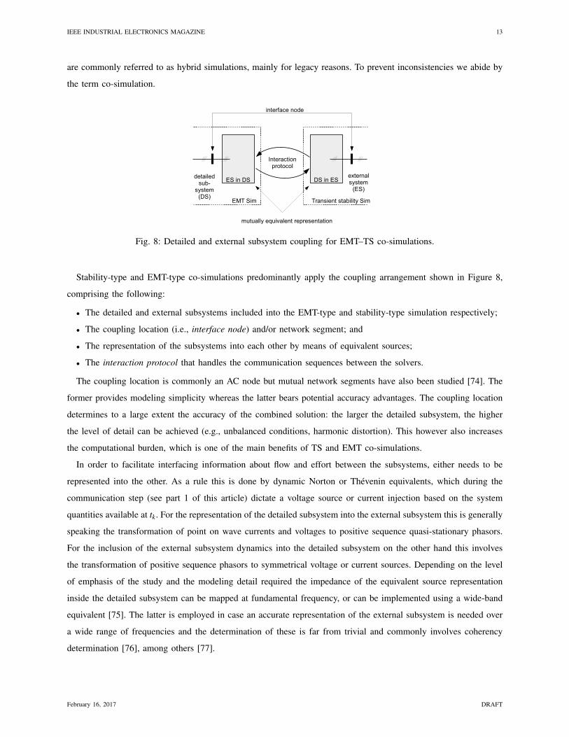
Fig. 8: Detailed and external subsystem coupling for EMT–TS co-simulations.
Stability-type and EMT-type co-simulations predominantly apply the coupling arrangement shown in Figure 8,
comprising the following:
• The detailed and external subsystems included into the EMT-type and stability-type simulation respectively;
• The coupling location (i.e., interface node) and/or network segment; and
• The representation of the subsystems into each other by means of equivalent sources;
• The interaction protocol that handles the communication sequences between the solvers.
The coupling location is commonly an AC node but mutual network segments have also been studied [74]. The
former provides modeling simplicity whereas the latter bears potential accuracy advantages. The coupling location
determines to a large extent the accuracy of the combined solution: the larger the detailed subsystem, the higher
the level of detail can be achieved (e.g., unbalanced conditions, harmonic distortion). This however also increases
the computational burden, which is one of the main benefits of TS and EMT co-simulations.
In order to facilitate interfacing information about flow and effort between the subsystems, either needs to be
represented into the other. As a rule this is done by dynamic Norton or Thevenin equivalents, which during the
communication step (see part 1 of this article) dictate a voltage source or current injection based on the system
quantities available at tk. For the representation of the detailed subsystem into the external subsystem this is generally
speaking the transformation of point on wave currents and voltages to positive sequence quasi-stationary phasors.
For the inclusion of the external subsystem dynamics into the detailed subsystem on the other hand this involves
the transformation of positive sequence phasors to symmetrical voltage or current sources. Depending on the level
of emphasis of the study and the modeling detail required the impedance of the equivalent source representation
inside the detailed subsystem can be mapped at fundamental frequency, or can be implemented using a wide-band
equivalent [75]. The latter is employed in case an accurate representation of the external subsystem is needed over
a wide range of frequencies and the determination of these is far from trivial and commonly involves coherency
determination [76], among others [77].
February 16, 2017 DRAFT
IEEE INDUSTRIAL ELECTRONICS MAGAZINE 14
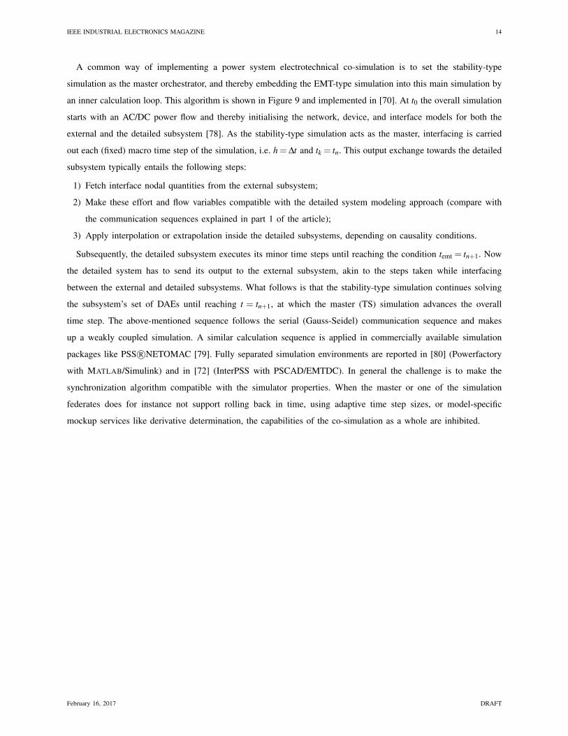
A common way of implementing a power system electrotechnical co-simulation is to set the stability-type
simulation as the master orchestrator, and thereby embedding the EMT-type simulation into this main simulation by
an inner calculation loop. This algorithm is shown in Figure 9 and implemented in [70]. At t0 the overall simulation
starts with an AC/DC power flow and thereby initialising the network, device, and interface models for both the
external and the detailed subsystem [78]. As the stability-type simulation acts as the master, interfacing is carried
out each (fixed) macro time step of the simulation, i.e. h = ∆t and tk = tn. This output exchange towards the detailed
subsystem typically entails the following steps:
1) Fetch interface nodal quantities from the external subsystem;
2) Make these effort and flow variables compatible with the detailed system modeling approach (compare with
the communication sequences explained in part 1 of the article);
3) Apply interpolation or extrapolation inside the detailed subsystems, depending on causality conditions.
Subsequently, the detailed subsystem executes its minor time steps until reaching the condition temt = tn+1. Now
the detailed system has to send its output to the external subsystem, akin to the steps taken while interfacing
between the external and detailed subsystems. What follows is that the stability-type simulation continues solving
the subsystem’s set of DAEs until reaching t = tn+1, at which the master (TS) simulation advances the overall
time step. The above-mentioned sequence follows the serial (Gauss-Seidel) communication sequence and makes
up a weakly coupled simulation. A similar calculation sequence is applied in commercially available simulation
packages like PSS R©NETOMAC [79]. Fully separated simulation environments are reported in [80] (Powerfactory
with MATLAB/Simulink) and in [72] (InterPSS with PSCAD/EMTDC). In general the challenge is to make the
synchronization algorithm compatible with the simulator properties. When the master or one of the simulation
federates does for instance not support rolling back in time, using adaptive time step sizes, or model-specific
mockup services like derivative determination, the capabilities of the co-simulation as a whole are inhibited.
February 16, 2017 DRAFT
IEEE INDUSTRIAL ELECTRONICS MAGAZINE 15
Fig. 9: Workflow of an electrotechnical EMT–TS co-simulation, in which the transient stability simulation acts as
the master simulator.
C. Co-Simulation Implementation for VSC-HVDC
The next generation of HVDC transmission based on voltage sourced converter technology (VSC-HVDC) has
the potential to transmit power in the GW range. Despite the superior controllability of such interconnections, the
AC/DC interactions cannot be safely disregarded in grid integration studies, particularly during fault-ride through
conditions [81]. This gives rise to co-simulation applications. This section gives an survey of the functionality
requirements of the co-simulation environment.
From an operation viewpoint VSC-HVDC links can be mainly separated into 3 types: offshore wind power
plant connections, VSC-HVDC links embedded in one synchronous area, and multi-terminal schemes. The control
design of point-to-point links primarily focuses on 1) conveying the active power infeed towards the opposite VSC
terminal, 2) device and HVDC primary equipment protection, and 3) ancillary services. Active power set points
are typically set by either the system operator or imposed by the wind power plant output. Fault-ride through of
point-to-point links is commonly achieved using overvoltage protection devices inside the DC link (i.e., dynamic
breaking resistors), whereas fault interruption is done via the AC side. Strictly speaking, point-to-point VSC-HVDC
schemes do not need any (fast) communication that might suddenly inflict unexpected behavior at the AC-side.
Multi-terminal schemes do not comply very well to this concept as DC faults should be cleared selectively, the
direction of active power flow shall be controllable, and sophisticated fault-ride through and/or ancillary services
must be engaged.
This operational functionality also puts a burden on the simulation and modeling needs. fault-ride through might
engage lower level (component-specific) protection mechanisms such as converter module blocking, which on their
turn inflict severe perturbations in the power output. Such events necessitate the inclusion of a wide spectrum of
February 16, 2017 DRAFT
IEEE INDUSTRIAL ELECTRONICS MAGAZINE 16
physical phenomena into the overall (physical) system assessment. Another notable domain of interest is the (fast)
communication needs of VSC-HVDC links. The inclusion of ICT-specific models into the overall system assessment
is more effective using a dedicated domain-specific model and corresponding solution algorithm.
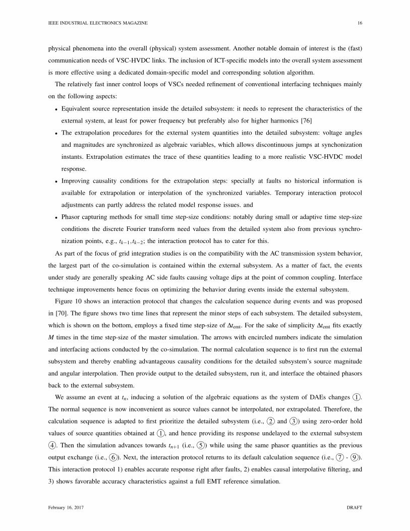
The relatively fast inner control loops of VSCs needed refinement of conventional interfacing techniques mainly
on the following aspects:
• Equivalent source representation inside the detailed subsystem: it needs to represent the characteristics of the
external system, at least for power frequency but preferably also for higher harmonics [76]
• The extrapolation procedures for the external system quantities into the detailed subsystem: voltage angles
and magnitudes are synchronized as algebraic variables, which allows discontinuous jumps at synchonization
instants. Extrapolation estimates the trace of these quantities leading to a more realistic VSC-HVDC model
response.
• Improving causality conditions for the extrapolation steps: specially at faults no historical information is
available for extrapolation or interpolation of the synchronized variables. Temporary interaction protocol
adjustments can partly address the related model response issues. and
• Phasor capturing methods for small time step-size conditions: notably during small or adaptive time step-size
conditions the discrete Fourier transform need values from the detailed system also from previous synchro-
nization points, e.g., tk−1, tk−2; the interaction protocol has to cater for this.
As part of the focus of grid integration studies is on the compatibility with the AC transmission system behavior,
the largest part of the co-simulation is contained within the external subsystem. As a matter of fact, the events
under study are generally speaking AC side faults causing voltage dips at the point of common coupling. Interface
technique improvements hence focus on optimizing the behavior during events inside the external subsystem.
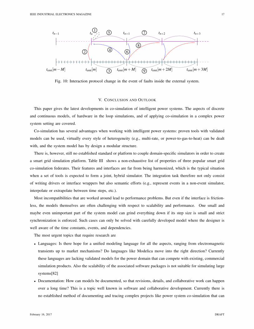
Figure 10 shows an interaction protocol that changes the calculation sequence during events and was proposed
in [70]. The figure shows two time lines that represent the minor steps of each subsystem. The detailed subsystem,
which is shown on the bottom, employs a fixed time step-size of ∆temt. For the sake of simplicity ∆temt fits exactly
M times in the time step-size of the master simulation. The arrows with encircled numbers indicate the simulation
and interfacing actions conducted by the co-simulation. The normal calculation sequence is to first run the external
subsystem and thereby enabling advantageous causality conditions for the detailed subsystem’s source magnitude
and angular interpolation. Then provide output to the detailed subsystem, run it, and interface the obtained phasors
back to the external subsystem.
We assume an event at tn, inducing a solution of the algebraic equations as the system of DAEs changes 1 .
The normal sequence is now inconvenient as source values cannot be interpolated, nor extrapolated. Therefore, the
calculation sequence is adapted to first prioritize the detailed subsystem (i.e., 2 and 3 ) using zero-order hold
values of source quantities obtained at 1 , and hence providing its response undelayed to the external subsystem
4 . Then the simulation advances towards tn+1 (i.e., 5 ) while using the same phasor quantities as the previous
output exchange (i.e., 6 ). Next, the interaction protocol returns to its default calculation sequence (i.e., 7 - 9 ).
This interaction protocol 1) enables accurate response right after faults, 2) enables causal interpolative filtering, and
3) shows favorable accuracy characteristics against a full EMT reference simulation.
February 16, 2017 DRAFT
IEEE INDUSTRIAL ELECTRONICS MAGAZINE 17
tn−1 tn tn+1 tn+2 tn+3
temt[m−M] temt[m] temt[m+M] temt[m+2M] temt[m+3M]
1
2
3
4
5
6
7
8
9
Fig. 10: Interaction protocol change in the event of faults inside the external system.
V. CONCLUSION AND OUTLOOK
This paper gives the latest developments in co-simulation of intelligent power systems. The aspects of discrete
and continuous models, of hardware in the loop simulations, and of applying co-simulation in a complex power
system setting are covered.
Co-simulation has several advantages when working with intelligent power systems: proven tools with validated
models can be used, virtually every style of heterogeneity (e.g., multi-rate, or power-to-gas-to-heat) can be dealt
with, and the system model has by design a modular structure.
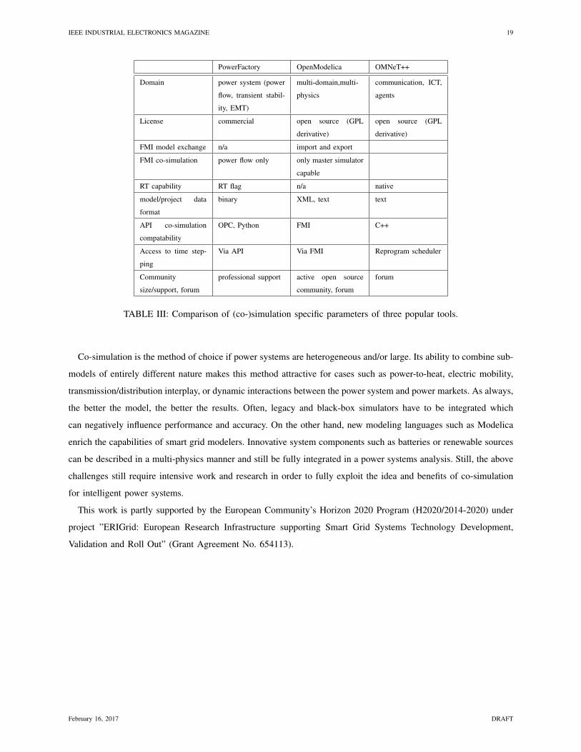
There is, however, still no established standard or platform to couple domain-specific simulators in order to create
a smart grid simulation platform. Table III shows a non-exhaustive list of properties of three popular smart grid
co-simulation federates. Their features and interfaces are far from being harmonized, which is the typical situation
when a set of tools is expected to form a joint, hybrid simulator. The integration task therefore not only consist
of writing drivers or interface wrappers but also semantic efforts (e.g., represent events in a non-event simulator,
interpolate or extrapolate between time steps, etc.).
Most incompatibilities that are worked around lead to performance problems. But even if the interface is friction-
less, the models themselves are often challenging with respect to scalability and performance. One small and
maybe even unimportant part of the system model can grind everything down if its step size is small and strict
synchronization is enforced. Such cases can only be solved with carefully developed model where the designer is
well aware of the time constants, events, and dependencies.
The most urgent topics that require research are
• Languages: Is there hope for a unified modeling language for all the aspects, ranging from electromagnetic
transients up to market mechanisms? Do languages like Modelica move into the right direction? Currently
these languages are lacking validated models for the power domain that can compete with existing, commercial
simulation products. Also the scalability of the associated software packages is not suitable for simulating large
systems[82]
• Documentation: How can models be documented, so that revisions, details, and collaborative work can happen
over a long time? This is a topic well known in software and collaborative development. Currently there is
no established method of documenting and tracing complex projects like power system co-simulation that can
February 16, 2017 DRAFT
IEEE INDUSTRIAL ELECTRONICS MAGAZINE 18
easily be deployed.
• Formats: Which standards are the most promising for time series, parameters, libraries or components [83]?
Emerging standards like hdf5 (hierarchical data format) and XML-based industry standards should be sufficient
for these needs. Many tools, however, still use comma-separated value lists and other non-descriptive formats.
• Distributed computing: How can we split large systems into parts to run them on a distributed computing
environment? Platforms like HLA are prepared for distributed computing. The key point, however, is perfor-
mance, which in turn boils down to how the used hardware and the compilers/software are balanced against
each other. Most known parallel attempts use nodes connected via general-purpose communication networks,
which is far away from real parallel computation.
• Multi-granular models: How can we define models with different levels of details to perform a coarse analysis
on the simple ones and to dive into the details once something interesting is discovered. What role can object-
oriented modeling languages play in this question? Models in Modelica could incorporate different version of
the component behavior, e.g., a static, a linearized and a detailed. Depending on the simulation run, one of
them can be activated. This could help to quickly chart the search space and later investigate the interesting
areas.
• Complexity: System complexity rises dramatically if a formerly continuous system is enhanced with digital
elements that show memory (digital controllers and software in general do that). The number of system states
explodes and validating system behavior becomes a difficult task. Is an exhaustive search needed when varying
parameters or are smart optimization algorithms capable of exploiting the peculiarities of intelligent power grid
models? Modern hybrid metaheuristics are much more efficient in searching complex spaces. It is an active
field of research where we still expect substantial progress [84].
• Heterogeneous models: How can we combine statistical models, topological models, physical models, and all
the other ways that provide valuable information of our intelligent power systems? If aspects are optimized in
one model domain, how can we harmonize that with the others? The need for multiple languages in describing
systems led to the development of the unified modeling language UML. While it has gained substantial
acceptance in other domains, it did unfortunately not receive much resonance in the power domain except
its use in InterPSS, CIM (Common Information Model, based on UML), and some academic projects.
• Numerics: How do uncertainties in input data or model data propagate through co-simulation? Do individual
model inaccuracies and solver errors add up or multiply when combined? This is a highly complicated topic.
How errors propagate and how uncertainties live on in a complex simulation is an active field of research [85].
• Validation: How to validate results when a monolithic simulation is not longer possible and therefore no
benchmark exists? Model validation is expensive if it is done via real experiments. The classical workaround
is to validate against another established and accepted model or tool. Co-simulation can simulate systems
that are too large for monolithic, validated tools, which therefore can not serve as a validation benchmark
[86]. The only workaround available for this dilemma is to use a mix of experiments and different flavors of
co-simulation to validate the simulators against each other [87].
February 16, 2017 DRAFT
IEEE INDUSTRIAL ELECTRONICS MAGAZINE 19
PowerFactory OpenModelica OMNeT++
Domain power system (power
flow, transient stabil-
ity, EMT)
multi-domain,multi-
physics
communication, ICT,
agents
License commercial open source (GPL
derivative)
open source (GPL
derivative)
FMI model exchange n/a import and export
FMI co-simulation power flow only only master simulator
capable
RT capability RT flag n/a native
model/project data
format
binary XML, text text
API co-simulation
compatability
OPC, Python FMI C++
Access to time step-
ping
Via API Via FMI Reprogram scheduler
Community
size/support, forum
professional support active open source
community, forum
forum
TABLE III: Comparison of (co-)simulation specific parameters of three popular tools.
Co-simulation is the method of choice if power systems are heterogeneous and/or large. Its ability to combine sub-
models of entirely different nature makes this method attractive for cases such as power-to-heat, electric mobility,
transmission/distribution interplay, or dynamic interactions between the power system and power markets. As always,
the better the model, the better the results. Often, legacy and black-box simulators have to be integrated which
can negatively influence performance and accuracy. On the other hand, new modeling languages such as Modelica
enrich the capabilities of smart grid modelers. Innovative system components such as batteries or renewable sources
can be described in a multi-physics manner and still be fully integrated in a power systems analysis. Still, the above
challenges still require intensive work and research in order to fully exploit the idea and benefits of co-simulation
for intelligent power systems.
This work is partly supported by the European Community’s Horizon 2020 Program (H2020/2014-2020) under
project ”ERIGrid: European Research Infrastructure supporting Smart Grid Systems Technology Development,
Validation and Roll Out” (Grant Agreement No. 654113).
February 16, 2017 DRAFT
IEEE INDUSTRIAL ELECTRONICS MAGAZINE 20
REFERENCES
[1] A. Vojdani, “Smart integration,” IEEE Power and Energy Magazine, vol. 6, no. 6, pp. 71–79, Nov. 2008.
[2] P. Palensky and F. Kupzog, “Smart grids,” Annual Reviews of Environment and Resources, vol. 38, pp. 201–226, 11 2013.
[3] R. Green, L. Wang, and M. Alam, “Applications and trends of high performance computing for electric power systems: Focusing on smart
grid,” IEEE Transactions on Smart Grid, vol. 4, no. 2, pp. 922–931, Jun. 2013.
[4] S. Chatzivasileiadis, M. Bonvini, J. Matanza, R. Yin, T. S. Nouidui, E. C. Kara, R. Parmar, D. Lorenzetti, M. Wetter, and S. Kiliccote,
“Cyber-pysical modeling of distributed resources for distribution system operations,” Proc. IEEE, vol. 104, no. 4, pp. 789 – 806, Apr.
2016.
[5] F. Guo, L. Herrera, R. Murawski, E. Inoa, C.-L. Wang, P. Beauchamp, E. Ekici, and J. Wang, “Comprehensive real-time simulation of the
smart grid,” Industry Applications, IEEE Transactions on, vol. 49, no. 2, pp. 899–908, 2013.
[6] B. Asghari, V. Dinavahi, M. Rioual, J. Martinez, and R. Iravani, “Interfacing techniques for electromagnetic field and circuit simulation
programs,” IEEE Transactions on Power Delivery, vol. 24, no. 2, pp. 939 –950, Apr. 2009.
[7] V. Jalili-Marandi and V. Dinavahi, “Large-scale transient stability simulation on graphics processing units,” in Proceedings of Power &
Energy Society General Meeting, 2009. PES’09. IEEE, Calgary, Alberta Canada, Jul. 2009.
[8] Z. Zhou and V. Dinavahi, “Parallel massive-thread electromagnetic transient simulation on GPU,” IEEE Transactions on Power Delivery,
vol. 29, no. 3, pp. 1045–1053, Jun. 2014.
[9] M. O. Faruque, V. Dinavahi, M. Steurer, A. Monti, K. Strunz, J. A. Martinez, G. W. Chang, J. Jatskevich, R. Iravani, and A. Davoudi,
“Interfacing issues in multi-domain simulation tools,” IEEE Trans. Power Del., vol. 27, no. 1, pp. 439–448, Jan. 2012.
[10] C. Molitor, S. Gross, J. Zeitz, and A. Monti, “Mescos — a multienergy system cosimulator for city district energy systems,” IEEE
Transactions on Industrial Informatics, vol. 10, no. 4, pp. 2247–2256, Nov 2014.
[11] J. B. Soyez, G. Morvan, R. Merzouki, and D. Dupont, “Multilevel agent-based modeling of system of systems,” IEEE Systems Journal,
vol. PP, no. 99, pp. 1–12, 2015.
[12] H. Lin, S. Sambamoorthy, S. Shukla, J. Thorp, and L. Mili, “A study of communication and power system infrastructure interdependence
on PMU-based wide area monitoring and protection,” in Proceedings of 2012 IEEE Power & Energy Society General Meeting, San Diego,
CA, Jul. 2012.
[13] R. Bottura, A. Borghetti, F. Napolitano, and C. A. Nucci, “ICT-power co-simulation platform for the analysis of communication-based
volt/var optimization in distribution feeders,” in Proceedings of 2014 IEEE PES Innovative Smart Grid Technologies Conference (ISGT),
Washington DC, Feb. 2014.
[14] M. Armendariz, M. Chenine, L. Nordstrom, and A. Al-Hammouri, “A co-simulation platform for medium/low voltage monitoring and
control applications,” in Proceedings of 2014 IEEE PES Innovative Smart Grid Technologies Conference (ISGT), Feb. 2014.
[15] C. Dufour and J. Belanger, “On the use of real-time simulation technology in smart grid research and development,” IEEE Transactions
on Industrial Applications, vol. 50, no. 6, pp. 3963–3970, Apr. 2014.
[16] D. Burnier de Castro, S. Ubermasser, S. Henein, M. Stifter, J. Stockl, and S. Hoglinger, “Dynamic co-simulation of agent-based controlled
charging electric vehicles and their impacts on low-voltage networks,” in Proceedings of 2013 IEEE International Workshop on Intelligent
Energy Systems (IWIES), Vienna, Austria, Nov. 2013, pp. 82–88.
[17] J. H. Kazmi, A. Latif, I. Ahmad, P. Palensky, and W. Gawlik, “A flexible smart grid co-simulation environment for cyber-physical
interdependence analysis,” in Proceedings of Workshop Modeling and Simulation of Cyber-Physical Energy Systems (MSCPES), Vienna,
Austria, Apr. 2016.
[18] M. Wei and W. Wang, “Greenbench: A benchmark for observing power grid vulnerability under data-centric threats,” in Proceedings of
IEEE INFOCOM 2014 - IEEE Conference on Computer Communications, Toronto, ON, Canada, Apr. 2014, pp. 2625–2633.
[19] M. Mallouhi, Y. Al-Nashif, D. Cox, T. Chadaga, and S. Hariri, “A testbed for analyzing security of SCADA control systems (TASSCS),”
in Proceedings of 2011 IEEE PES Innovative Smart Grid Technologies Conference (ISGT), Anaheim, CA, Jan. 2011.
[20] I. Ahmad, J. H. Kazmi, M. Shahzad, P. Palensky, and W. Gawlik, “Co-simulation framework based on power system, AI and communication
tools for evaluating smart grid applications,” in Proceedings of IEEE Innovative Smart Grid Technologies - Asia (ISGT ASIA), Bangkok,
Thailand, Nov 2015.
[21] G. Zhabelova and V. Vyatkin, “Multiagent smart grid automation architecture based on IEC 61850/61499 intelligent logical nodes,” IEEE
Transactions on Industrial Electronics, vol. 59, no. 5, pp. 2351–2362, May 2012.
February 16, 2017 DRAFT
IEEE INDUSTRIAL ELECTRONICS MAGAZINE 21
[22] C. Yang, G. Zhabelova, C. W. Yang, and V. Vyatkin, “Cosimulation environment for event-driven distributed controls of smart grid,” IEEE
Transactions on Industrial Informatics, vol. 9, no. 3, pp. 1423–1435, Aug 2013.
[23] M. Stifter, J. H. Kazmi, F. Andren, and T. Strasser, “Co-simulation of power systems, communication and controls,” in Modeling and
Simulation of Cyber-Physical Energy Systems (MSCPES), 2014 Workshop on, April 2014, pp. 1–6.
[24] K. Hopkinson, X. Wang, R. Giovanini, J. Thorp, K. Birman, and D. Coury, “EPOCHS: A platform for agent-based electric power and
communication simulation built from commercial off-the-shelf components,” IEEE Transactions on Power Systems, vol. 21, no. 2, pp.
548–558, May 2006.
[25] H. Lin, S. Veda, S. Shukla, L. Mili, and J. Thorp, “GECO: Global event-driven co-simulation framework for interconnected power system
and communication network,” IEEE Transactions on Smart Grid, vol. 3, no. 3, pp. 1444–1456, May 2012.
[26] H. Georg, S. Muller, C. Rehtanz, and C. Wietfeld, “Analyzing cyber-physical energy systems: The INSPIRE cosimulation of power and
ICT systems using HLA,” IEEE Transactions on Industrial Informatics, vol. 10, no. 4, pp. 2364–2373, Jun. 2014.
[27] D. Bhor, K. Angappan, and K. M. Sivalingam, “A co-simulation framework for smart grid wide-area monitoring networks,” in Proceedings
of 2014 Sixth International Conference on Communication Systems and Networks (COMSNETS), Bangalore, India, Jan. 2014.
[28] J. Nutaro, P. T. Kuruganti, L. Miller, S. Mullen, and M. Shankar, “Integrated hybrid-simulation of electric power and communications
systems,” in Proceedings of 2007 IEEE Power Engineering Society General Meeting, Tampa, FL, Jun. 2007.
[29] V. Liberatore and A. Al-Hammouri, “Smart grid communication and co-simulation,” in Proceedings of 2011 IEEE Energytech, Cleveland,
OH, May 2011.
[30] W. Li, A. Monti, M. Luo, and R. A. Dougal, “VPNET: A co-simulation framework for analyzing communication channel effects on power
systems,” in Proceedings of 2011 IEEE Electric Ship Technologies Symposium (ESTS), Alexandria, VA, USA, Apr. 2011, pp. 143–149.
[31] T. Godfrey, S. Mullen, R. C. Dugan, C. Rodine, D. W. Griffith, and N. Golmie, “Modeling smart grid applications with co-simulation,” in
Proceedings of Smart Grid Communications (SmartGridComm), 2010 First IEEE International Conference on, Gaithersburg, MD, USA,
Oct. 2010, pp. 291–296.
[32] K. Mets, J. A. Ojea, and C. Develder, “Combining power and communication network simulation for cost-effective smart grid analysis,”
IEEE Communications Surveys & Tutorials, vol. 16, no. 3, pp. 1771–1796, Mar. 2014.
[33] C. S. Edrington, M. Steurer, J. Langston, T. El-Mezyani, and K. Schoder, “Role of power hardware in the loop in modeling and simulation
for experimentation in power and energy systems,” Proc. IEEE, vol. 103, no. 12, pp. 2401–2409, Dec. 2015.
[34] M. Omar Faruque, T. Strasser, G. Lauss, V. Jalili-Marandi, P. Forsyth, C. Dufour, V. Dinavahi, A. Monti, P. Kotsampopoulos, J. Martinez,
K. Strunz, M. Saeedifard, X. Wang, D. Shearer, and M. Paolone, “Real-time simulation technologies for power systems design, testing,
and analysis,” IEEE Power and Energy Technology Systems Journal, vol. 2, no. 2, pp. 63–73, Jun. 2015.
[35] G. Lauss, M. Faruque, K. Schoder, C. Dufour, A. Viehweider, and J. Langston, “Characteristics and design of power hardware-in-the-loop
simulations for electrical power systems,” IEEE Transactions on Industrial Electronics, vol. 63, no. 1, pp. 406–417, Jan. 2016.
[36] W. Ren, “Accuracy evaluation of power hardware-in-the-loop (PHIL) simulation,” Ph.D. dissertation, Florida State University, Florida,
USA, 2007.
[37] P. McLaren, R. Kuffel, R. Wierckx, J. Giesbrecht, and L. Arendt, “A real time digital simulator for testing relays,” IEEE Transactions on
Power Delivery, vol. 7, no. 1, pp. 207–213, Jan. 1992.
[38] H. Aghamolki, Z. Miao, and L. Fan, “A hardware-in-the-loop SCADA testbed,” in Proceedings of North American Power Symposium
(NAPS), 2015, Charlotte, NC, USA, Oct. 2015, pp. 1–6.
[39] M. Almas and L. Vanfretti, “RT-HIL implementation of hybrid synchrophasor and GOOSE-based passive islanding schemes,” IEEE
Transactions on Power Delivery, vol. PP, no. 99, pp. 1–1, Aug. 2015.
[40] D. Mascarella, M. Chlela, G. Joos, and P. Venne, “Real-time testing of power control implemented with IEC 61850 GOOSE messaging
in wind farms featuring energy storage,” in Proceedings of 2015 IEEE Energy Conversion Congress and Exposition (ECCE), Montreal,
QC, Canada, Sep. 2015, pp. 6710–6715.
[41] B. Xiao, M. Starke, G. Liu, B. Ollis, P. Irminger, A. Dimitrovski, K. Prabakar, K. Dowling, and Y. Xu, “Development of hardware-in-the-
loop microgrid testbed,” in Proceedings of 2015 IEEE Energy Conversion Congress and Exposition (ECCE), Montreal, QC, Canada, Sep.
2015, pp. 1196–1202.
[42] A. Shrestha, V. Cecchi, and R. Cox, “A real-time platform for validating continuous wide-area control systems,” in Proceedings of 2013
IEEE PES Innovative Smart Grid Technologies (ISGT), Washington, DC, Feb. 2013.
[43] S. T. Cha, Q. Wu, A. Nielsen, J. Ostergaard, and I. K. Park, “Real-time hardware-in-the-loop (HIL) testing for power electronics controllers,”
in Proceedings of 2012 Asia-Pacific Power and Energy Engineering Conference (APPEEC), Shanghai, China, Mar. 2012, pp. 1–6.
February 16, 2017 DRAFT
IEEE INDUSTRIAL ELECTRONICS MAGAZINE 22
[44] Y. Liu, Z. Xi, Z. Liang, W. Song, S. Bhattacharya, A. Huang, J. Langston, M. Steurer, W. Litzenberger, L. Anderson, R. Adapa, and
A. Sundaram, “Controller hardware-in-the-loop validation for a 10 MVA ETO-based STATCOM for wind farm application,” in Proceedings
of IEEE Energy Conversion Congress and Exposition, 2009. ECCE 2009, San Jose, CA, USA, Sep. 2009, pp. 1398–1403.
[45] C. Edrington, O. Vodyakho, B. Hacker, S. Azongha, A. Khaligh, and O. Onar, “Virtual battery charging station utilizing power-hardware-
in-the-loop: Application to V2G impact analysis,” in Proceedings of 2010 IEEE Vehicle Power and Propulsion Conference (VPPC), Lille,
France, Sep. 2010.
[46] R. Sharma, W. U. Qiuwei, S. T. Cha, K. H. Jensen, T. W. Rasmussen, and J. Østegaard, “Power hardware in the loop validation of fault
ride through of VSC HVDC connected offshore wind power plants,” Journal of Modern Power Systems and Clean Energy, vol. 2, no. 1,
pp. 23–29, Mar. 2014.
[47] J. Leonard, R. Hadidi, and J. Fox, “Real-time modeling of multi-level megawatt class power converters for hardware-in-the-loop testing,”
in Proceedings of 2015 International Symposium on Smart Electric Distribution Systems and Technologies (EDST), Vienna, Austria, Sep.
2015, pp. 566–571.
[48] G.-J. Park, H. Jung, Y.-J. Kim, and S.-Y. Jung, “Multi-domain co-simulation with numerically identified PMSM interworking at HILS for
electric propulsion,” in Proceedings of Power Electronics Conference (IPEC-Hiroshima 2014 - ECCE-ASIA), 2014 International, Hiroshima,
Japan, May 2014, pp. 1990–1996.
[49] C. Molitor, A. Benigni, A. Helmedag, K. Chen, D. Cali, P. Jahangiri, D. Muller, and A. Monti, “Multiphysics test bed for renewable
energy systems in smart homes,” IEEE Transactions on Industrial Electronics, vol. 60, no. 3, pp. 1235–1248, Mar. 2013.
[50] S. Rotger-Griful, S. Chatzivasileiadis, R. H. Jacobsen, E. M. Stewart, J. M. Domingo, and M. Wetter, “Hardware-in-the-loop co-simulation
of distribution grid for demand response,” in 2016 Power Systems Computation Conference (PSCC), Jun. 2016.
[51] M. H. Syed, P. Crolla, G. M. Burt, and J. K. Kok, “Ancillary service provision by demand side management: A real-time power hardware-in-
the-loop co-simulation demonstration,” in 2015 International Symposium on Smart Electric Distribution Systems and Technologies (EDST),
Sep. 2015, pp. 492–498.
[52] B. Jablkowski, O. Spinczyk, M. Kuech, and C. Rehtanz, “A hardware-in-the-loop co-simulation architecture for power system applications
in virtual execution environments,” in Proceedings of 2014 Workshop on Modeling and Simulation of Cyber-Physical Energy Systems
(MSCPES), Berlin, Germany, Apr. 2014.
[53] B. Palmintier, B. Lundstrom, S. Chakraborty, T. Williams, K. Schneider, and D. Chassin, “A power hardware-in-the-loop platform with
remote distribution circuit cosimulation,” IEEE Transactions on Industrial Electronics, vol. 62, no. 4, pp. 2236–2245, Apr. 2015.
[54] C. B. Vellaithurai, S. S. Biswas, R. Liu, and A. Srivastava, “Real time modeling and simulation of cyber-power system,” in Cyber Physical
Systems Approach to Smart Electric Power Grid. Springer-Verlag Berlin Heidelberg, 2015, pp. 43–74.
[55] B. Chen, K. L. Butler-Purry, A. Goulart, and D. Kundur, “Implementing a real-time cyber-physical system test bed in RTDS and OPNET,”
in Proceedings of North American Power Symposium (NAPS), 2014, Pullman, WA, Sep. 2014.
[56] V. Venkataramanan, A. Srivastava, and A. Hahn, “Real-time co-simulation testbed for microgrid cyber-physical analysis,” in 2016 Workshop
on Modeling and Simulation of Cyber-Physical Energy Systems (MSCPES), Apr. 2016.
[57] D. Babazadeh, M. Chenine, K. Zhu, L. Nordstrom, and A. Al-Hammouri, “A platform for wide area monitoring and control system ICT
analysis and development,” in Proceedings of PowerTech (POWERTECH), 2013 IEEE Grenoble, Grenoble, France, Jun. 2013.
[58] A. Hahn, A. Ashok, S. Sridhar, and M. Govindarasu, “Cyber-physical security testbeds: Architecture, application, and evaluation for smart
grid,” IEEE Transactions on Smart Grid, vol. 4, no. 2, pp. 847–855, Mar. 2013.
[59] P. Mutschler, “Programs for transient studies of generators connected with HVDC converters and their control system,” in Proceedings of
6th Power Systems Computation Conference, Darmstadt, Germany, Aug. 1978, pp. 823–827.
[60] J. Arrillaga and I. Elamin, “Transient stability performance of a 3-machine system including an h.v d.c. link,” Proceedings of the Institution
of Electrical Engineers, vol. 123, no. 11, pp. 1239 –1244, Nov. 1976.
[61] J. Arrillaga, H. Al-Khashali, and J. Campos-Barros, “General formulation for dynamic studies in power systems including static convertors,”
Proceedings of the Institution of Electrical Engineers, vol. 124, no. 11, pp. 1047 –1052, Nov. 1977.
[62] G. Carter, C. Grund, H. Happ, and R. Pohl, “The dynamics of AC/DC systems with controlled multiterminal HVDC transmission,” IEEE
Transactions on Power Apparatus and Systems, vol. 96, no. 2, pp. 402–413, Mar. 1977.
[63] M. Heffernan, K. Turner, J. Arrillaga, and C. Arnold, “Computation of A.C.-D.C. system disturbances - Parts I, II, and III. interactive
coordination of generator and convertor transient models,” IEEE Transactions on Power Apparatus and Systems, vol. PAS-100, no. 11, pp.
4341 –4363, Nov. 1981.
February 16, 2017 DRAFT
IEEE INDUSTRIAL ELECTRONICS MAGAZINE 23
[64] J. Reeve and R. Adapa, “A new approach to dynamic analysis of AC networks incorporating detailed modeling of DC systems - Parts I
and II,” IEEE Transactions on Power Delivery, vol. 3, no. 4, pp. 2005 –2019, Oct. 1988.
[65] M. Sultan, J. Reeve, and R. Adapa, “Combined transient and dynamic analysis of HVDC and FACTS systems,” IEEE Transactions on
Power Delivery, vol. 13, no. 4, pp. 1271–1277, Oct 1998.
[66] G. Anderson, N. Watson, N. Arnold, and J. Arrillaga, “A new hybrid algorithm for analysis of HVDC and FACTS systems,” in Proceedings
of International Conference Energy Management and Power Delivery, vol. 2, Nov. 1995, pp. 462–467.
[67] B. Kasztenny and M. Kezunovic, “A method for linking different modeling techniques for accurate and efficient simulation,” IEEE
Transactions on Power Systems, vol. 15, no. 1, pp. 65 – 72, Feb. 2000.
[68] H. Su, K. Chan, and L. Snider, “Parallel interaction protocol for electromagnetic and electromechanical hybrid simulation,” IEE Proceedings-
Generation, Transmission and Distribution, vol. 152, no. 3, pp. 406–414, May 2005.
[69] H. Inabe, T. Futada, H. Horii, and K. Inomae, “Development of an instantaneous and phasor analysis combined type real-time digital
power system simulator,” in Proceedings International Conference on Power Systems Transients, New Orleans, LA, 2003.
[70] A. A. van der Meer, M. Gibescu, M. A. M. M. van der Meijden, W. L. Kling, and J. A. Ferreira, “Advanced hybrid transient stability and
EMT simulation for VSC-HVDC systems,” IEEE Transactions on Power Delivery, vol. 30, no. 3, pp. 1057–1066, Jun. 2015, .
[71] F. Plumier, P. Aristidou, C. Geuzaine, and T. V. Cutsem, “Co-simulation of electromagnetic transients and phasor models: A relaxation
approach,” IEEE Transactions on Power Delivery, vol. PP, no. 99, pp. 1–1, Mar. 2016.
[72] Q. Huang and V. Vittal, “Application of electromagnetic transient - transient stability hybrid simulation to FIDVR study,” IEEE Transactions
on Power Systems, vol. PP, no. 99, pp. 1–13, Sep. 2015, accepted for publication.
[73] S. Zadkhast, J. Jatskevich, and E. Vaahedi, “A multi-decomposition approach for accelerated time-domain simulation of transient stability
problems,” IEEE Trans. Power Syst., vol. 30, no. 5, pp. 2301–2311, Sep. 2015.
[74] A. Semlyen and M. Iravani, “Frequency domain modeling of external systems in an electro-magnetic transients program,” IEEE Transactions
on Power Systems, vol. 8, no. 2, pp. 527 –533, May 1993.
[75] X. Lin, A. Gole, and M. Yu, “A wide-band multi-port system equivalent for real-time digital power system simulators,” IEEE Transactions
on Power Systems, vol. 24, no. 1, pp. 237 –249, Feb. 2009.
[76] Y. Liang, X. Lin, A. Gole, and M. Yu, “Improved coherency-based wide-band equivalents for real-time digital simulators,” IEEE
Transactions on Power Systems, vol. 26, no. 3, pp. 1410 – 1417, Aug. 2011.
[77] U. Annakkage, N. Nair, Y. Liang, A. Gole, V. Dinavahi, B. Gustavsen, T. Noda, H. Ghasemi, A. Monti, M. Matar, R. Iravani, and
J. Martinez, “Dynamic system equivalents: A survey of available techniques,” IEEE Transactions on Power Delivery, vol. 27, no. 1, pp.
411 –420, Jan. 2012.
[78] J. Beerten, S. Cole, and R. Belmans, “Generalized steady-state VSC MTDC model for sequential AC/DC power flow algorithms,” IEEE
Transactions on Power Systems, vol. 27, no. 2, pp. 821 –829, May 2012.
[79] G. Deiml, C. Hahn, W. Winter, and M. Luther, “A novel dynamic model for multiterminal HVDC systems based on self-commutated full-
and half-bridge multilevel voltage sourced converters,” in Proceedings of Power Electronics and Applications (EPE’14-ECCE Europe),
2014 16th European Conference on, Finland, Aug. 2014, pp. 1–13.
[80] X. Kong, X. Yu, R. R. Chan, and M. Y. Lee, “Co-simulation of a marine electrical power system using powerfactory and MAT-
LAB/simulink,” in Proceedings of 2013 IEEE Electric Ship Technologies Symposium (ESTS), Apr. 2013, pp. 62–65.
[81] A. A. van der Meer, M. Ndreko, M. Gibescu, and M. A. M. M. van der Meijden, “The effect of FRT behavior of VSC-HVDC connected
offshore wind power plants on AC/DC system dynamics,” IEEE Transactions on Power Delivery, vol. 31, no. 2, pp. 878–887, Mar. 2016.
[82] P. Palensky, E. Widl, and A. Elsheikh, “Simulating cyber-physical energy systems: challenges, tools and methods,” IEEE Transactions on
Systems, Man, and Cybernetics, vol. 44, no. 3, pp. 318–326, 2013.
[83] A. Pakonen, C. Pang, I. Buzhinsky, and V. Vyatkin, “User-friendly formal specification languages - conclusions drawn from industrial
experience on model checking,” in 2016 IEEE 21st International Conference on Emerging Technologies and Factory Automation (ETFA),
Sep. 2016.
[84] J. L. Rueda, J. Cepeda, I. Erlich, D. Echeverria, and G. Arguello, “Heuristic optimization based approach for identification of power system
dynamic equivalents,” International Journal of Electrical Power & Energy Systems, vol. 64, pp. 185–193, 2015.
[85] C. Steinbrink and S. Lehnhoff, “Challenges and necessity of systematic uncertainty quantification in smart grid co-simulation,” in
EUROCON 2015 - International Conference on Computer as a Tool (EUROCON), IEEE, Sept 2015, pp. 1–6.
[86] I. Buzhinsky, C. Pang, and V. Vyatkin, “Formal modeling of testing software for cyber-physical automation systems,” in Trust-
com/BigDataSE/ISPA, 2015 IEEE, vol. 3, Aug 2015, pp. 301–306.
February 16, 2017 DRAFT

IEEE INDUSTRIAL ELECTRONICS MAGAZINE 24
[87] T. Strasser, F. Andren, G. Lauss, R. Brundlinger, H. Brunner, C. Moyo, C. Seitl, S. Rohjans, S. Lehnhoff, P. Palensky, P. Kotsampopoulos,
N. Hatziargyriou, G. Arnold, W. Heckmann, E. De Jong, M. Verga, G. Franchioni, L. Martini, A. Kosek, O. Gehrke, H. Bindner, F. Coffele,
G. Burt, and M. Valin, “Towards holistic power distribution system validation and testing - an overview and discussion of different
possibilities,” in Proc. CIGRE Session 2016, Paris, France, Aug. 2016.
February 16, 2017 DRAFT
IEEE INDUSTRIAL ELECTRONICS MAGAZINE 25
PLACE
PHOTO
HERE
Peter Palensky (M’03-SM’05) is full Professor for intelligent electric power grids at TU Delft. Before that he was
Principal Scientist at the Austrian Institute of Technology (AIT), associate Professor at the University of Pretoria, South
Africa, Department of Electrical, Electronic and Computer Engineering, University Assistant at the Vienna University
of Technology, Austria, and researcher at the Lawrence Berkeley National Laboratory, California. He is active in
international committees like ISO, IEEE and CEN. His main research fields are energy automation networks, and
modeling intelligent energy systems.
PLACE
PHOTO
HERE
Arjen van der Meer (M’08) Arjen van der Meer - obtained the B.Sc. degree in electrical engineering at NHL University
of applied sciences, Leeuwarden, the Netherlands, in 2006. In 2008, he received the M.Sc. degree (Hons.) in electrical
engineering from Delft University of Technology, the Netherlands. Currently, he is working towards the Ph.D. degree
on the grid integration of offshore VSC-HVDC grids at Delft University of Technology. His main research topic is the
interconnection of large scale wind power to transnational offshore grids. His research interests include power system
computation, the modeling and simulation of smart grids, renewable energy sources, power electronic devices, and
protection systems.
PLACE
PHOTO
HERE
Claudio David Lopez (M’16) is a doctoral researcher in the Intelligent Electrical Power Grids group at the Delft
University of Technology. He obtained an M.Sc. in Energy Technologies from the Karlsruhe Institute of Technology
and Uppsala University in 2015 and an engineer’s degree in electronics from the University of Concepcion in 2009.
He has worked as a research assistant in the Fraunhofer Institute for Wind Energy and Energy System Technology and
as a consulting engineer on energy-related projects in the public and private sectors. His research interests are related
to co-simulation of complex and large-scale power systems.
PLACE
PHOTO
HERE
Arun Joseph obtained his bachelor degree (B.Tech) in electrical engineering from Calicut University, India in 2009
and master degree (M.Tech) in control system from Indian Institute of Technology, Kharagpur in 2012. He has worked
as a research assistant in aerospace department of Indian Institute of Science, Bangalore and senior research fellow
in power system division of Central Power Research Institute, Bangalore. Currently he is a doctoral researcher in the
Intelligent Electrical Power Grids group at the Delft University of Technology and research areas include real-time
model validation of power system using co-simulation techniques, hardware-in-the-loop methods.
February 16, 2017 DRAFT

IEEE INDUSTRIAL ELECTRONICS MAGAZINE 26
PLACE
PHOTO
HERE
Kaikai Pan (M’16) received the B.Eng. and M. Eng. Degrees in measuring and control from Beihang University,
Beijing, China, in 2012 and 2015, respectively. Currently he is working towards the Ph.D. degree in the Intelligent
Electrical Power Grids group from Delft University of Technology, Delft, The Netherlands. His research interests
include cyber-physical energy systems, cyber security of intelligent power grids, risk assessment for data attacks, and
co-simulation techniques.
February 16, 2017 DRAFT
IEEE INDUSTRIAL ELECTRONICS MAGAZINE 27
LIST OF FIGURES
1 Use case with a PV plant, an inverter with communicating controller, and a distribution grid (middle),
that can be analyzed in a full co-sim fashion (upper setup) or in real-time with the real inverter in the
loop (lower setup). . . . . . . . . . . . . . . . . . . . . . . . . . . . . . . . . . . . . . . . . . . . . . 3
2 Time scales of various power grid applications based on [32]. . . . . . . . . . . . . . . . . . . . . . . 5
3 Real time guarantees and time scales of power system communication protocols. . . . . . . . . . . . 6
4 Basic structure of CHIL and PHIL simulation. . . . . . . . . . . . . . . . . . . . . . . . . . . . . . . 7
5 Ideal transformer method for interfacing power hardware and a real time digital simulator. . . . . . . 8
6 Hardware in the Loop Co-Simulation Architecture [52]. . . . . . . . . . . . . . . . . . . . . . . . . . 10
7 Concept of multiphysics PHIL platform based on [49]. . . . . . . . . . . . . . . . . . . . . . . . . . . 11
8 Detailed and external subsystem coupling for EMT–TS co-simulations. . . . . . . . . . . . . . . . . . 13
9 Workflow of an electrotechnical EMT–TS co-simulation, in which the transient stability simulation
acts as the master simulator. . . . . . . . . . . . . . . . . . . . . . . . . . . . . . . . . . . . . . . . . 15
10 Interaction protocol change in the event of faults inside the external system. . . . . . . . . . . . . . . 17
LIST OF TABLES
I Examples of co-simulation of power systems and ICT infrastructure . . . . . . . . . . . . . . . . . . . 5
II Summary of features of real time simulators for power systems. . . . . . . . . . . . . . . . . . . . . . 9
III Comparison of (co-)simulation specific parameters of three popular tools. . . . . . . . . . . . . . . . . 19
February 16, 2017 DRAFT