Embed Size (px)
DESCRIPTION
Mixers
Citation preview

Created in COMSOL Multiphysics 5.1
M i x e r
All trademarks are the property of their respective owners. See www.comsol.com/trademarks.

About the Mixer Application
The purpose of the Mixer application is to provide a user-friendly interface where scientists, process designers, and process engineers can investigate the influence that vessel, impeller, and operational conditions have on the mixing efficiency and the power required to drive the impellers. The app can be used to understand and optimize the design and operation of the mixer for a given fluid. But, maybe most importantly, it can be used as a starting point for your own app for the modeling and simulation of mixers and reactors.
The application demonstrates how parts and cumulative selections can be used to automatically set domain and boundary settings in the embedded models. These settings can be created automatically, even when the choices an app user makes create very diverse geometries.
O V E R V I E W
There are three different types of tanks that you can specify in your simulation: Dished bottom tanks, flat bottom tanks, and cone bottom tanks.
There are eleven different types of impellers: Six axial impellers and five radial impellers.
The app simulates mixers with a single impeller shaft with one or several impeller turbines (see the figure below). The tank can be equipped with baffles in order to improve mixing. Baffles are especially required when radial impellers are used.
The workflow in the Mixer app is quite straightforward and the annotated screenshot below shows the main steps. Start by defining the operating conditions, which include the fluid properties and the rotational speed of the impellers.
Dished bottom tank Flat bottom tank Cone bottom tank
Example of axial impeller Example of radial impeller
2 | M I X E R
0
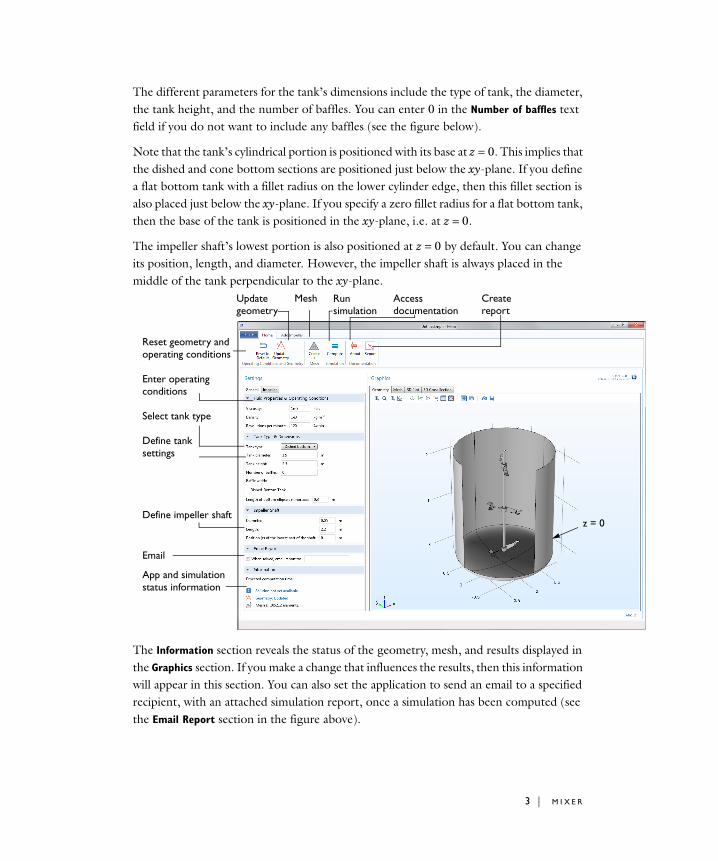
The different parameters for the tank’s dimensions include the type of tank, the diameter, the tank height, and the number of baffles. You can enter 0 in the Number of baffles text field if you do not want to include any baffles (see the figure below).
Note that the tank’s cylindrical portion is positioned with its base at z = 0. This implies that the dished and cone bottom sections are positioned just below the xy-plane. If you define a flat bottom tank with a fillet radius on the lower cylinder edge, then this fillet section is also placed just below the xy-plane. If you specify a zero fillet radius for a flat bottom tank, then the base of the tank is positioned in the xy-plane, i.e. at z = 0.
The impeller shaft’s lowest portion is also positioned at z = 0 by default. You can change its position, length, and diameter. However, the impeller shaft is always placed in the middle of the tank perpendicular to the xy-plane.
The Information section reveals the status of the geometry, mesh, and results displayed in the Graphics section. If you make a change that influences the results, then this information will appear in this section. You can also set the application to send an email to a specified recipient, with an attached simulation report, once a simulation has been computed (see the Email Report section in the figure above).
z =
Reset geometry andoperating conditions
Enter operatingconditions
Select tank type
Define tank settings
Define impeller shaft
App and simulationstatus information
Update Mesh Run Access geometry simulation documentation
Createreport
3 | M I X E R

You can add impellers by clicking the Add Impeller tab in the Ribbon in the Windows® operating system, or by clicking the Add Impeller button on Linux® and Mac® operating systems. This adds an item to the Impeller list. Several impellers can be added to the same shaft and distributed along its height by specifying the positions along the z-axis. In order to change the settings of an impeller, select it in the list, make the desired change in the settings fields, and click the Update Geometry button. Make sure to click this button, otherwise the changes will not take effect.
The dimensions and configuration of the different impellers can be controlled to a great extent. For example, if you select a pitched impeller, you can cut different areas, round its edges, define the pitch angle, and define asymmetrical blades, which are wider above the rotation plane than below. If you add several impellers to a shaft, you can also rotate them slightly around the z-axis in order to evenly distribute the blades when viewed from above in an xy-plane projection (see the θ angles in the figure below)
The application results show the velocity field, both in a 3D cut plane and in the form of 3D streamlines. In addition, a cross-section plot shows the eddy diffusivity and the streamlines within the yz-plane in the center of the mixer. Note also that the shape of the free liquid surface is calculated and that the cross-section plane can be rotated around the main axis (see the figure below). The 3D cross section scales the deformation of the shape
θ1
θ2
θ3
Add Impeller tab
Impeller list
Impeller dimensionsand position
Direction ofimpeller position
Impeller bladeshape
4 | M I X E R
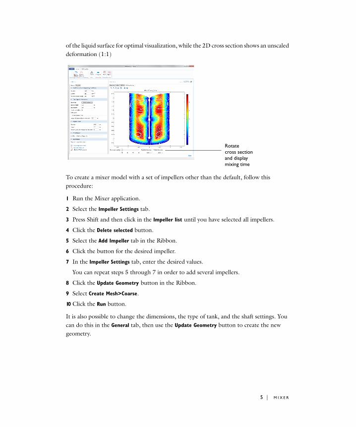
of the liquid surface for optimal visualization, while the 2D cross section shows an unscaled deformation (1:1)
To create a mixer model with a set of impellers other than the default, follow this procedure:
1 Run the Mixer application.
2 Select the Impeller Settings tab.
3 Press Shift and then click in the Impeller list until you have selected all impellers.
4 Click the Delete selected button.
5 Select the Add Impeller tab in the Ribbon.
6 Click the button for the desired impeller.
7 In the Impeller Settings tab, enter the desired values.
You can repeat steps 5 through 7 in order to add several impellers.
8 Click the Update Geometry button in the Ribbon.
9 Select Create Mesh>Coarse.
10 Click the Run button.
It is also possible to change the dimensions, the type of tank, and the shaft settings. You can do this in the General tab, then use the Update Geometry button to create the new geometry.
Rotatecross sectionand displaymixing time
5 | M I X E R

Impeller Types
As mentioned above, there are two different types of impellers included in COMSOL Multiphysics: Axial and radial impellers.
Axial impellers give the flow an axial component that provides mixing along the z-axis of the mixer. This type of mixer is appropriate for fluids that are sensitive to high shear rates. For example, fermentation processes have living cells in the reactor solution, which would be killed by high shear rates. In these processes, axial impellers are often selected and baffles are usually omitted.
Radial impellers force the flow in the radial direction and only give an axial component once the flow hits the walls of the vessel. In order to achieve good mixing, these impellers rely on high shear rates and the presence of baffles, which disrupt tangential flows that would lead to poor mixing.
There is also an anchor impeller available, which is classified as a radial impeller, since it does not introduce an axial flow component. However, the anchor impeller does not induce a radial flow like a conventional radial impeller does.
When specifying the operation of all impellers included in COMSOL Multiphysics, the default direction is specified looking at the xy-plane from above. A positive angular velocity (ω) is defined as counterclockwise and clockwise is negative (see Figure 1 below).
The convention is valid for angles as well. A positive angle (θ) is defined as counterclockwise measured from the x-axis in the xy-plane.
The inner edges of the impeller blade are defined as the vertical edges closest to the hub and the outer edges are the vertical edges away from the hub.
Figure 1: Positive and negative angular velocity as defined in COMSOL Multiphysics.
6 | M I X E R
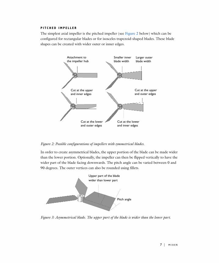
P I T C H E D I M P E L L E R
The simplest axial impeller is the pitched impeller (see Figure 2 below) which can be configured for rectangular blades or for isosceles trapezoid-shaped blades. These blade shapes can be created with wider outer or inner edges.
Figure 2: Possible configurations of impellers with symmetrical blades.
In order to create asymmetrical blades, the upper portion of the blade can be made wider than the lower portion. Optionally, the impeller can then be flipped vertically to have the wider part of the blade facing downwards. The pitch angle can be varied between 0 and 90 degrees. The outer vertices can also be rounded using fillets.
Figure 3: Asymmetrical blade. The upper part of the blade is wider than the lower part.
Attachment tothe impeller hub
Larger outerblade width
Smaller innerblade width
Cut at the upperand inner edges
Cut at the lowerand outer edges
Cut at the lowerand inner edges
Cut at the upperand outer edges
Upper part of the bladewider than lower part
Pitch angle
7 | M I X E R

The figure below contains the notation used for the pitched impeller in the Part Library. The full list of parameters and their descriptions are found in Table 1.
Figure 4: Notation used for the pitched impeller.
P I T C H E D I M P E L L E R W I T H B E N T B L A D E S
A bend may be used to decrease the pitch in the outer region (away from the hub) of the impeller blade. Bending results in a less aggressive pitch angle at the outer edges. Only the upper and outer edges of the blades can be bent in COMSOL Multiphysics. However, you can flip the impeller vertically to obtain a bend or wider part that faces downwards. The upper portion can also be made wider than the lower portion to obtain an asymmetrical blade.
Figure 5: Available blade bend and cut operations.
Attachment tothe impeller hub
Rectangularblade bend
Asymmetricblade
Blade bend at theupper and outer edges
Cut at the lowerand outer edges
Bendangle
Cut at the upperand inner edges
8 | M I X E R

The vertices of the outer vertical edge can be rounded using fillets. The figure below shows an impeller with asymmetrical blades and rounded vertices.
Figure 6: Asymmetrical impeller blades with rounded outer vertices.
The figure below contains the notations used for the pitched impeller with bent blades in the Part Library. The full list of parameters together with their descriptions is found in Table 1.
Figure 7: Notation used for the pitched impeller with bent blades.
Fillets create a rounded bend
Cut upper andinner edges
9 | M I X E R

P I T C H E D B L A D E I M P E L L E R W I T H C O N S T A N T P I T C H
For regular pitched impellers, the pitch increases with the radius of the impeller blades, since the blades travel with increasing velocity as the radius increases. This means that if the rotating impeller was allowed to move freely in the axial direction, the outer edge of a regular pitched impeller will want to travel at a higher axial velocity than the inner edge. This subjects the impeller blade to a high bending moment. The pitched impeller with constant pitch adapts the pitch angle with the increasing radius so that the outer and inner edges have the same axial velocity during rotation.
The impeller with constant pitch can be designed with isosceles trapezoid-shaped blade projections (the blades are not flat). The blades can also be cut on both upper and lower edges to achieve different impeller shapes (see figure below).
Figure 8: Pitched impellers with constant pitch and different blade shapes.
The inner pitch angle can be varied in order to change the axial and radial components of the flow induced by the impeller. The pitch angle is then automatically calculated to give a constant pitch.
Attachment tothe impeller hub
“Twisted”rectangular blade
Smaller innerblade width
Larger outerblade width
Cut upper andinner edges
Cut upper andouter edges
Cut lower andouter edges
Cut lower andinner edges
10 | M I X E R

The outer vertices of the blades can be rounded, which gives additional freedom in the design. The figure below shows a propeller created by using fillets and cuts and applying those on a pitched impeller with constant pitch.
Figure 9: Impeller of propeller type created using isosceles trapezoid-shaped blade projections and large fillet radii for the outer vertices of the blades.
The figure below contains the notations used for the pitched impeller with constant pitch in the Part Library. The full list of parameters with their descriptions is found in Table 1.
Figure 10: Notation used for the pitched impeller with constant pitch.
Fillet on upperand outer vertex
Fillet on lowerand outer vertex
Large fillet radiusyields a propeller shape
11 | M I X E R

H Y D R O F O I L I M P E L L E R
Impellers with blades that are curved along the vertical edges are called hydrofoil impellers. These are similar to pitched blade impellers, but give an additional pressure difference across the blade with a lowered pressure on the convex side.
In addition to varying the curvature radius of the blades, the shape of the impeller blade projections can be varied to achieve the same freedom in the design of hydrofoil impellers as in the case of the pitched impeller mentioned above. This implies that isosceles trapezoid-shaped blade projections, asymmetrical blades with a wider upper part, and cut blades can be used to create the desired design. Fillets make it possible to create impellers of the propeller type.
As in the case of the pitched impeller type, the pitch angle can be varied to control the relation between the radial and axial flow created as the impeller rotates.
Figure 11: The curved blades can be shaped to create a large variety of impeller designs.
Rectangular curvedblade with attachment at the hub
Asymmetrical blade with widerupper part of the blade
Curvedblades
Flipvertical
Fliphorizontal
Large filletradius
Cut upper andinner edges
Cut lower andouter edges
12 | M I X E R

The figure below contains the notations used for the hydrofoil impeller in the Part Library. The full list of parameters with their descriptions is found in Table 1.
Figure 12: Notation used for the hydrofoil impeller.
13 | M I X E R

H Y D R O F O I L I M P E L L E R W I T H C O N S T A N T P I T C H
In the same fashion as the pitched impeller, the hydrofoil impeller creates an axial flow velocity that increases with the radius as the impeller rotates. This subjects the blade to a bending moment. A hydrofoil impeller with constant pitch adapts the pitch angle in order to obtain an almost constant pitch of the projection of the curved blade along the radius. Note that it is very difficult to obtain an exactly constant pitch with increasing radius since the blades are curved.
As in the case of regular hydrofoil impellers, the hydrofoil impeller with constant pitch gives an additional pressure difference across the blade with a lowered pressure on the convex side.
The impeller blade can be designed with cut blades and asymmetrical blades. Fillets can be used to create impellers of the propeller type.
Figure 13: Hydrofoil impellers with constant pitch.
Rectangular curvedand twisted blade
Cut upper andinner edges
Cut lower andouter edges
Cut widerouter edge
Large filletradius
Cut lower andouter edges with fillets
14 | M I X E R

The figure below contains the notation used for the hydrofoil impeller with constant pitch in the Part Library. The full list of parameters with their descriptions is found in Table 1.
Figure 14: Notation used for the hydrofoil with constant pitch.
15 | M I X E R

T H E C - S H A P E D D O U B L E B L A D E I M P E L L E R
This is an axial impeller that is suitable for fluids with relatively high viscosity. It consists of two pitched blades equipped with a c-shaped double-blade part that adds shear at the outer radius. This configuration can be used to create the so-called Intermig® impeller.
The impeller can be designed with different pitch angles on the arms. The angles of the c-shaped part can also be varied. The profile can be adjusted by changing the vertical angle of the c-shaped part while keeping the upper and lower blades parallel. In addition, the angle of the back of the “c” can be varied while keeping the lower and upper blades parallel but displacing them in the xy-plane.
Figure 15: The c-shaped double blade impeller.
C-shapeddouble blade
Adapt for clockwiseand counterclockwise rotation
Varying angle ofc-shaped profile
Varying pitch angle
Impeller arm
16 | M I X E R

The figure below contains the notations used for the c-shaped double blade impeller in the Part Library. The full list of parameters with their descriptions is found in Table 1.
Figure 16: Notation used for the c-shaped double blade impeller.
17 | M I X E R

R U S H T O N TU R B I N E
Axial impellers, such as the Rushton turbine, work by pumping the fluid towards the wall of the vessel and then letting the collision of the fluid with the wall supply the axial mixing and turbulence. In order to avoid tangential flows that would result in poor mixing, baffles are often used in combination with Rushton turbines. Rushton turbines induce a relatively high shear rate and are therefore appropriate in processes where the fluid is not sensitive to shear rates.
The turbine can be designed with different blade lengths and different disk diameters.
Figure 17: The Rushton turbine.
The figure below contains the notations used for the Rushton turbine in the Part Library. The full list of parameters with their descriptions is found in Table 1.
Figure 18: Notation used for the Rushton turbine.
Impeller blade
Impeller disk
18 | M I X E R

T H E R U S H T O N TU R B I N E W I T H B A C K S W E P T B L A D E S
This type of turbine is similar to the normal Rushton turbine. The backswept blades allow for smoother operation with lower shear rates. It is possible to vary the blade length and the disk diameter, as well as the curvature and blade angle relative to the perimeter of the disk.
Figure 19: The Rushton turbine with backswept blades.
The figure below contains the notations used for the Rushton turbine with backswept blades in the Part Library. The full list of parameters with their descriptions is found in Table 1.
Figure 20: Notation used for the Rushton turbine with backswept blades.
Direction ofrotation Impeller disk
Impeller blade
19 | M I X E R

T H E S M I T H TU R B I N E
This is a turbine that resembles the Rushton turbine. It has the same properties but somewhat smoother operation with lower shear rates. The length of the blades, the diameter of the disk, and the radius of curvature of the blades can be varied when creating the impeller geometry.
Figure 21: The Smith Turbine.
The figure below contains the notations used for the Smith turbine in the Part Library. The full list of parameters with their descriptions is found in Table 1.
Figure 22: Notation used for the Smith turbine.
Impeller blade
Direction ofrotation Impeller disk
20 | M I X E R

T H E B A C K S W E P T B L A D E I M P E L L E R
This impeller type is suitable for fluids with low viscosity and density, for example, gases. The curvature creates smooth operating conditions with relatively small shear rates compared to straight blades. The impeller can be designed with different blade lengths and curvatures.
Figure 23: The backswept impeller.
The figure below contains the notations used for the backswept blade impeller in the Part Library. The full list of parameters with their descriptions is found in Table 1.
Figure 24: Notation used for the backswept blade impeller.
Direction ofrotation
Curvatureradius
Attachment to the hub
Impellerblade
21 | M I X E R

A N C H O R I M P E L L E R
This impeller type is suitable for mixing fluids of very high viscosity, for example, Portland concrete and paints in small amounts. The lower portion of the impeller is shaped like an ellipse that is cut in the middle. The major axis is equal to the impeller diameter, while the minor axis is equal to the dished tank’s minor axis where the impeller is placed, minus the clearance between the impeller and tank wall.
Figure 25: Anchor impeller.
The figure below contains the notations used for the anchor impeller in the Part Library. The full list of parameters with their descriptions is found in Table 1.
Figure 26: Notations used for the anchor impeller.
Minor axis
Major axis
Upper hub
22 | M I X E R

e
wer
per
Overview of Impeller Parameters
The table below contains the names and descriptions of the input parameters used for the impellers in the Mixer Module Part Library.
TABLE 1: MIXER MODULE PART LIBRARY PARAMETERS
ab_ib Bending angle of folded section
ac_h_s_ib Shear angle, back of c-shape blades
ac_ib Vertical angle between arm and c-shaped blade
ac_s_ib Internal angle, c-shaped profile
ap_ib Pitch angle of impeller blade
ar_ib Rake angle of impeller
as_ib Relative rotation angle around shaft
d_a_ib Diameter of attachment section
d_hu Impeller hub diameter
d_id Diameter of impeller dish
d_im Impeller diameter
d_is Impeller shaft diameter
d_ta Tank diameter
Da Input diameter for turbulence model
db_im Distance of first impeller hub from bottom
dc_ib Blade width, c-shaped blades
h_an_im Height of anchor impeller
hp_im Impeller position
hp_is Position of the lowest part of the impeller shaft
l_ib Length of the impeller blades, Rushton, Smith
lc_ib Blade length, c-shaped blades
lr_bu_ib Relative position of the bending point along the length of thupper edge of the impeller blade
lr_cl_ib Relative position of cutting point along the length of the loedge
lr_cu_ib Relative position of cutting point along the length of the upedge
n_ib Number of blades
23 | M I X E R

pa_rd_im Parameter that controls the impeller blade direction, 1 = clockwise and -1 = counterclockwise
pa_ud_im Flip impeller vertically
rc_h_ib Curvature of backswept Rushton, Smith, and Backswept impeller
rc_v_ib Hydrofoil curvature radius closest to the hub
rf_ib Fillet radius of outer vertices
w_a_ib Blade attachment width
w_bou_ib Width of the folded section at the outer edge
w_cil_ib Width of inner and lower cut
w_ciu_ib Width of inner and upper cut
w_col_ib Width of outer and lower cut
w_cou_ib Width of outer and upper cut
w_ib Impeller blade width
w_o_ib Outer impeller width
wc_ib Blade distance, c-shaped blades
wc_o_ib Outer arm width for c-shaped impeller
wr_ai_ib Ratio between blade width and blade attachment
wr_asu_ib Asymmetry factor for upper part of the width of the impeller blade: 1 = symmetry, >1 = wider upper part
TABLE 1: MIXER MODULE PART LIBRARY PARAMETERS
24 | M I X E R

The Embedded Model
The physics behind the application is based on the Mixer Module’s rotating machinery formulation. The flow is defined by a so-called y+ algebraic turbulence model in combination with the momentum and mass conservation formulations in the Single-Phase Flow interface. The rotating mesh is formulated by the moving mesh interface using an arbitrary Lagrangian-Eulerian formulation for a sliding mesh approach in the domain that surrounds the impellers. This auxiliary domain is hidden in the application’s UI.
Figure 27: Cylindrical rotating domain enveloping the impeller and shaft.
The geometry is constructed using different parts available in the Parts Library of the Mixer Module. The tanks all include a cylindrical rotating domain that completely envelopes the impellers positioned along the central axis of the tank.
R E S U L T S
The results show the flow field, the eddy diffusivity created by turbulence, and the time scale for the mixing process.
The flow field visualizations help in assessing the pattern of the flow. For example, if the flow is mainly tangential, so that the fluid moves like a merry-go-round around the center, then you may consider adding baffles.
Cylindrical rotatingdomain
25 | M I X E R

Note also that you can rotate the position of the cross-section plane by clicking the slider bar in the Graphics section. It is possible to rotate the cross-section plane both in the 3D and in the 2D plots.
The cross-sectional plot shows the streamlines in a yz-plane along the main axis of the mixer. This gives a good indication of the level of compartmentalization of the flow, which may also be broken up by baffles or by a steeper impeller pitch angle.
Rotatecross section anddisplay mixing time
Rotatecross section anddisplay mixing time
26 | M I X E R

The eddy diffusivity field is a measure of the mixing efficiency. You can estimate the time scale of the mixing process by dividing a typical area by the value of the eddy diffusivity. The time scales for the radial and axial mixing is estimated and shown below the 2D and 3D plots in the user interface.
Note that the application also computes the shape of the free surface for the fluid. This reveals whether the position of the top impeller is too close to the surface, so that some mixing power is lost to the gas above the free surface.
Application Library path: Mixer_Module/Demo_Applications/mixer
27 | M I X E R


