Embed Size (px)
Citation preview
Applications – Power train – Engine blocks Table of Contents 2 Engine blocks ......................................................................................................................... 2
2.1 Introduction ...................................................................................................................... 2 2.2 Requirements for aluminium engine blocks..................................................................... 4 2.3 Design features................................................................................................................ 6
2.3.1 Basic engine concept ................................................................................................ 6 2.3.2 Bolting concept.......................................................................................................... 8 2.3.3 Open and closed deck concepts ............................................................................... 9
2.4 Pre-cast features and add-on parts ................................................................................. 9 2.5 Cast-in inserts ................................................................................................................ 11 2.6 Criteria for alloy selection............................................................................................... 13 2.7 Alloys: Composition and heat treatment ........................................................................ 14 2.8 Applicable casting processes......................................................................................... 15
2.8.1 High pressure die casting (HPDC) .......................................................................... 16 2.8.2 Squeeze casting...................................................................................................... 17 2.8.3 Gravity die casting (GDC) ....................................................................................... 18 2.8.4 Low pressure die casting (LPDC) ........................................................................... 19 2.8.5 Sand casting processes .......................................................................................... 20 2.8.6 Lost foam process (LFC)......................................................................................... 22
2.9 Outlook........................................................................................................................... 23
Version 2011 © European Aluminium Association ([email protected]) 1
2 Engine blocks
2.1 Introduction Literature:
Köhler, E.: Verbrennungsmotoren: Motormechanik, Berechnung und Auslegung des Hubkolbenmotors. Braunschweig, Wiesbaden: Vieweg, 1998. ATZ-MTZ-Fachbuch, ISBN 3-528-03108-5 — Chapter 4.5
Menne, R.J. and Rechs, M.: Optimierte Prozesse für die Großserie (Reduzierte Entwicklungszeiten bei Verbrennungsmotoren). Berlin: Springer, 1999
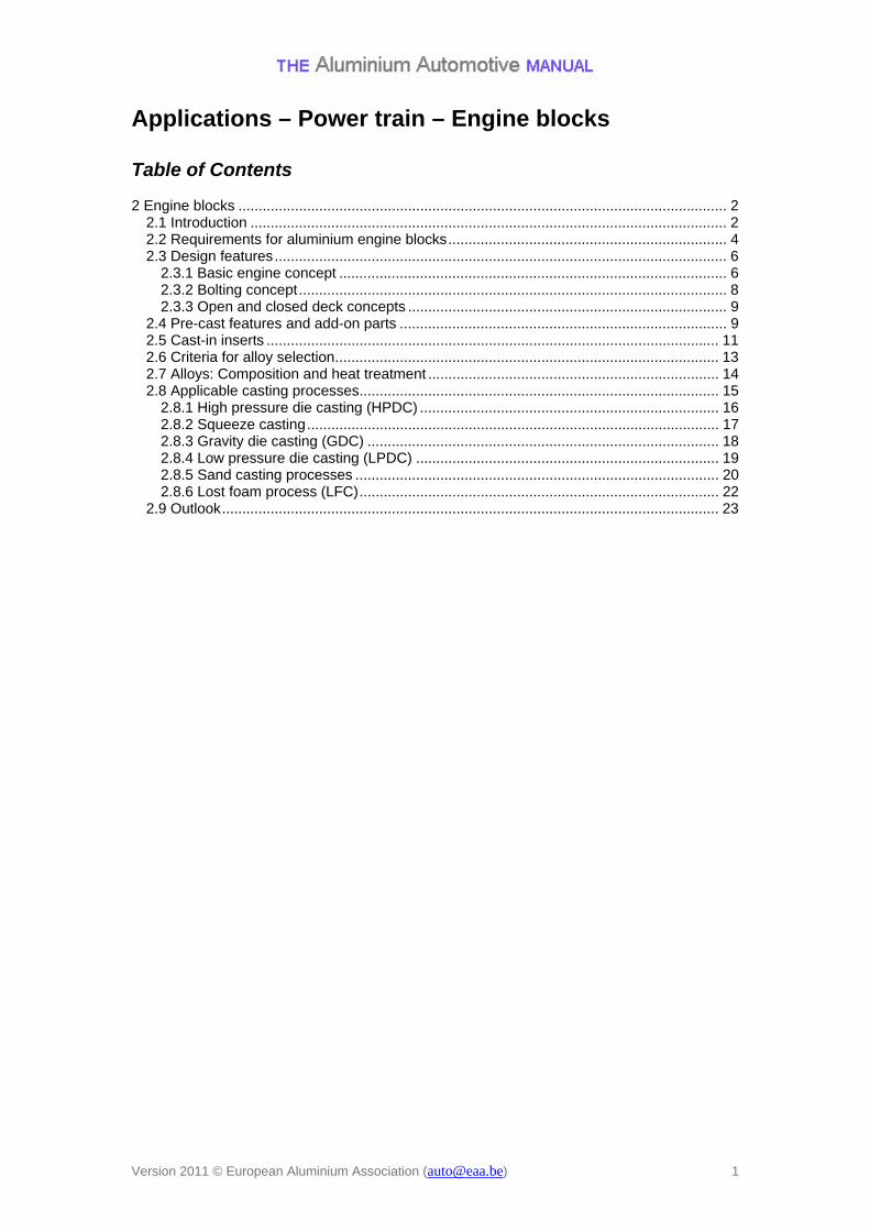
The suppliers of engine blocks are constantly striving to manufacture better and lighter blocks in order to improve and enhance the efficiency of automobile engines. The engine block (or cylinder block / crankcase) is the largest and most intricate single piece of metal used in an internal combustion engine on to which other important engine parts are mounted. Generally it is produced as a near net-shape casting and selectively machined to provide the locally required surface quality. The engine block alone accounts for 3-4% of the total weight of the average vehicle. Thus it played a key role in all weight-reduction considerations. Aluminium casting alloys as a substitute for the traditional cast iron can mean a reduction in engine block weight of between 40 and 55%, even if the lower strength of aluminium compared to grey cast iron is considered. The application of aluminium engine blocks started in gasoline engines in the late 1970s. Due to the more demanding technical requirements, however, substitution of cast iron was very limited in diesel engines until the mid 1990s. Only with the increasing numbers of diesel engines, the need to use lightweight design criteria was getting more and more important for diesel engines too. Around 2005, the market share of aluminium engine blocks reached 50% and its market penetration is further increasing. Today, blocks for gasoline engines are commonly made from aluminium and with the ongoing aluminium alloy developments, its application is also strongly growing in diesel engine blocks.
Production numbers of engine blocks in Western Europe (grey iron and aluminium cast alloys)
Version 2011 © European Aluminium Association ([email protected]) 2
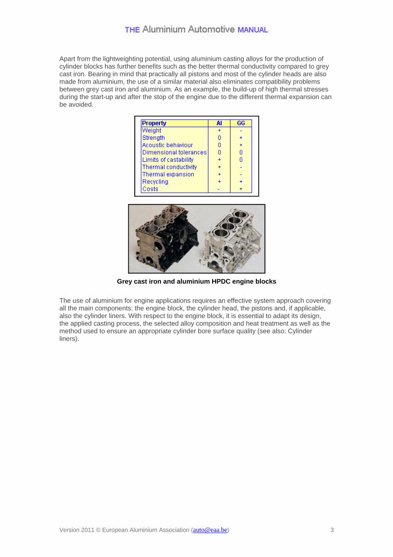
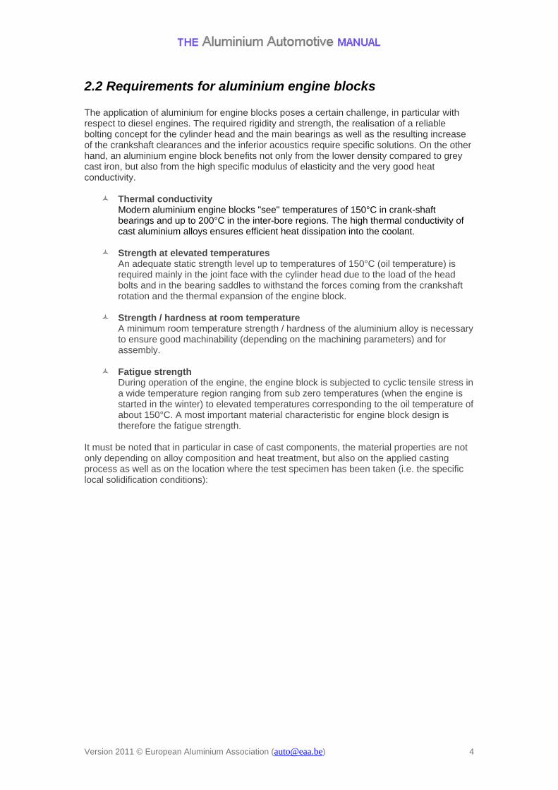
Apart from the lightweighting potential, using aluminium casting alloys for the production of cylinder blocks has further benefits such as the better thermal conductivity compared to grey cast iron. Bearing in mind that practically all pistons and most of the cylinder heads are also made from aluminium, the use of a similar material also eliminates compatibility problems between grey cast iron and aluminium. As an example, the build-up of high thermal stresses during the start-up and after the stop of the engine due to the different thermal expansion can be avoided.
Grey cast iron and aluminium HPDC engine blocks
The use of aluminium for engine applications requires an effective system approach covering all the main components: the engine block, the cylinder head, the pistons and, if applicable, also the cylinder liners. With respect to the engine block, it is essential to adapt its design, the applied casting process, the selected alloy composition and heat treatment as well as the method used to ensure an appropriate cylinder bore surface quality (see also: Cylinder liners).
Version 2011 © European Aluminium Association ([email protected]) 3
2.2 Requirements for aluminium engine blocks The application of aluminium for engine blocks poses a certain challenge, in particular with respect to diesel engines. The required rigidity and strength, the realisation of a reliable bolting concept for the cylinder head and the main bearings as well as the resulting increase of the crankshaft clearances and the inferior acoustics require specific solutions. On the other hand, an aluminium engine block benefits not only from the lower density compared to grey cast iron, but also from the high specific modulus of elasticity and the very good heat conductivity.
Thermal conductivity Modern aluminium engine blocks "see" temperatures of 150°C in crank-shaft bearings and up to 200°C in the inter-bore regions. The high thermal conductivity of cast aluminium alloys ensures efficient heat dissipation into the coolant.
Strength at elevated temperatures
An adequate static strength level up to temperatures of 150°C (oil temperature) is required mainly in the joint face with the cylinder head due to the load of the head bolts and in the bearing saddles to withstand the forces coming from the crankshaft rotation and the thermal expansion of the engine block.
Strength / hardness at room temperature
A minimum room temperature strength / hardness of the aluminium alloy is necessary to ensure good machinability (depending on the machining parameters) and for assembly.
Fatigue strength
During operation of the engine, the engine block is subjected to cyclic tensile stress in a wide temperature region ranging from sub zero temperatures (when the engine is started in the winter) to elevated temperatures corresponding to the oil temperature of about 150°C. A most important material characteristic for engine block design is therefore the fatigue strength.
It must be noted that in particular in case of cast components, the material properties are not only depending on alloy composition and heat treatment, but also on the applied casting process as well as on the location where the test specimen has been taken (i.e. the specific local solidification conditions):
Version 2011 © European Aluminium Association ([email protected]) 4
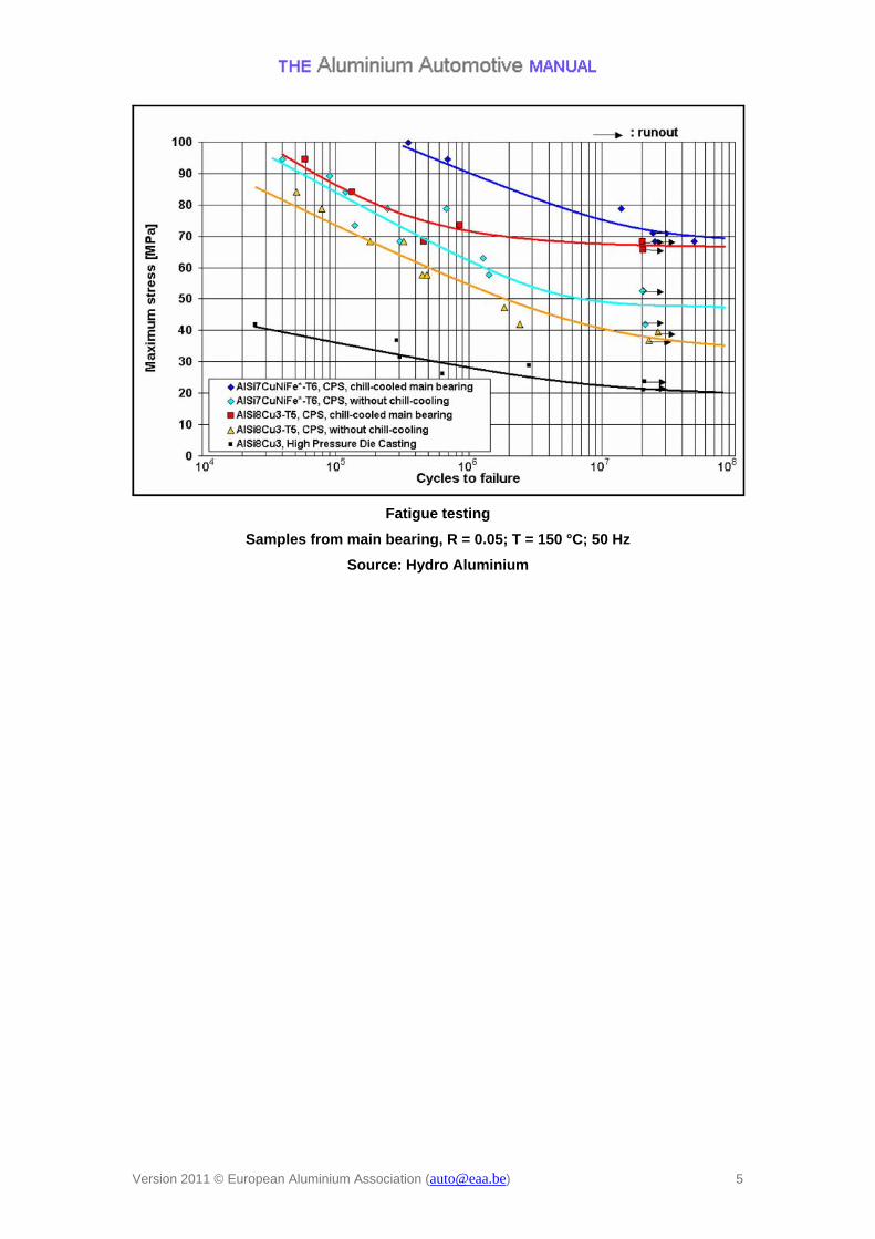
Fatigue testing
Samples from main bearing, R = 0.05; T = 150 °C; 50 Hz
Source: Hydro Aluminium
Version 2011 © European Aluminium Association ([email protected]) 5
2.3 Design features Literature:
Menne, R.J. and Rechs, M.: Optimierte Prozesse für die Großserie (Reduzierte Entwicklungszeiten bei Verbrennungsmotoren). Berlin: Springer, 1999 — Chapter 3.1.6
Metzner, F., u.a.: The New W Engines from Volkswagen with 8 and 12 Cylinders, MTZ 62, 2001, No.4, p.280-290
Tielkes, U., u.a.: Die neue Ottomotoren-Generation Duratec HE von Ford, MTZ 61, 2000, No.10, p.646-654
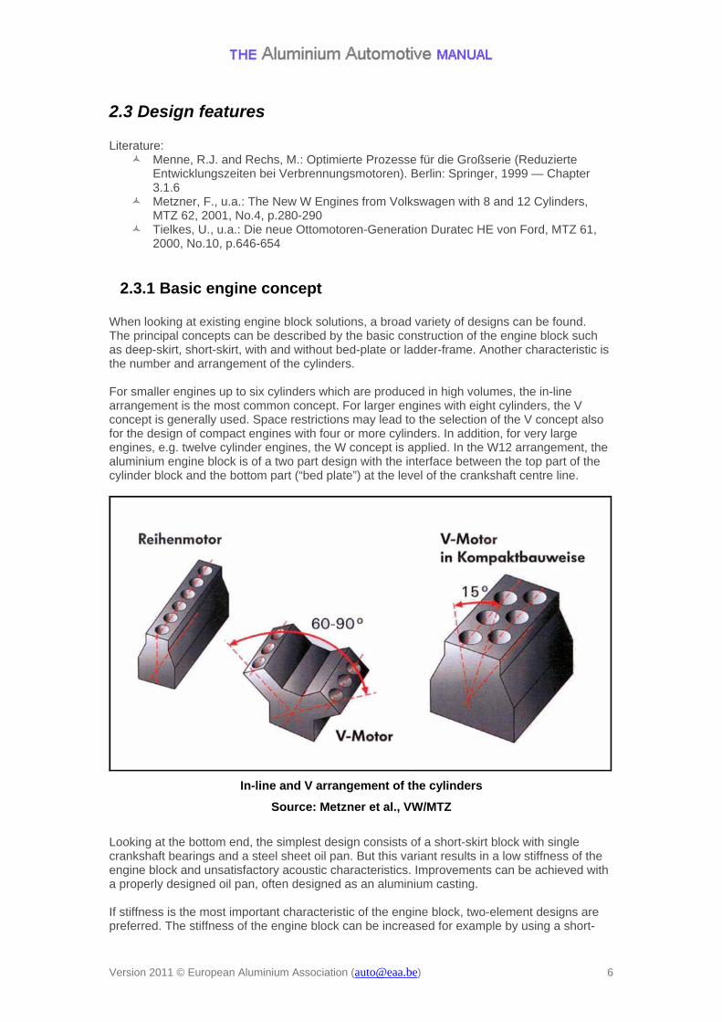
2.3.1 Basic engine concept When looking at existing engine block solutions, a broad variety of designs can be found. The principal concepts can be described by the basic construction of the engine block such as deep-skirt, short-skirt, with and without bed-plate or ladder-frame. Another characteristic is the number and arrangement of the cylinders. For smaller engines up to six cylinders which are produced in high volumes, the in-line arrangement is the most common concept. For larger engines with eight cylinders, the V concept is generally used. Space restrictions may lead to the selection of the V concept also for the design of compact engines with four or more cylinders. In addition, for very large engines, e.g. twelve cylinder engines, the W concept is applied. In the W12 arrangement, the aluminium engine block is of a two part design with the interface between the top part of the cylinder block and the bottom part (“bed plate”) at the level of the crankshaft centre line.
In-line and V arrangement of the cylinders
Source: Metzner et al., VW/MTZ
Looking at the bottom end, the simplest design consists of a short-skirt block with single crankshaft bearings and a steel sheet oil pan. But this variant results in a low stiffness of the engine block and unsatisfactory acoustic characteristics. Improvements can be achieved with a properly designed oil pan, often designed as an aluminium casting.
If stiffness is the most important characteristic of the engine block, two-element designs are preferred. The stiffness of the engine block can be increased for example by using a short-
Version 2011 © European Aluminium Association ([email protected]) 6
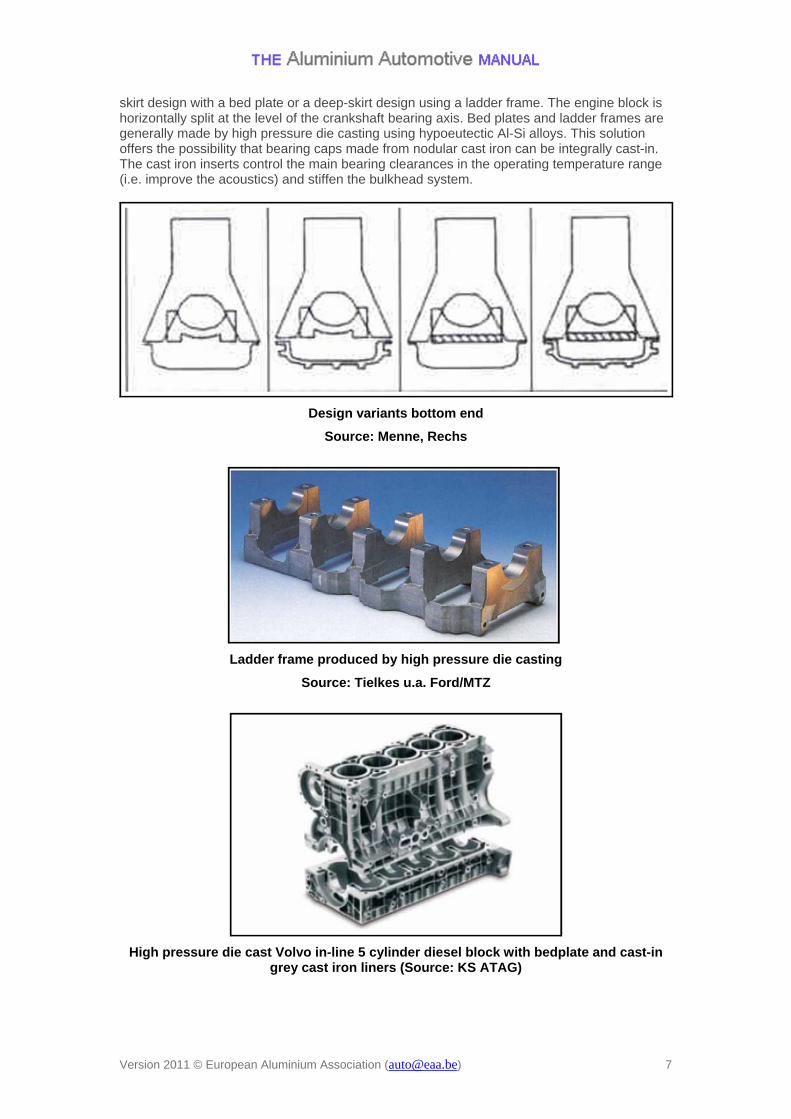
skirt design with a bed plate or a deep-skirt design using a ladder frame. The engine block is horizontally split at the level of the crankshaft bearing axis. Bed plates and ladder frames are generally made by high pressure die casting using hypoeutectic Al-Si alloys. This solution offers the possibility that bearing caps made from nodular cast iron can be integrally cast-in. The cast iron inserts control the main bearing clearances in the operating temperature range (i.e. improve the acoustics) and stiffen the bulkhead system.
Design variants bottom end
Source: Menne, Rechs
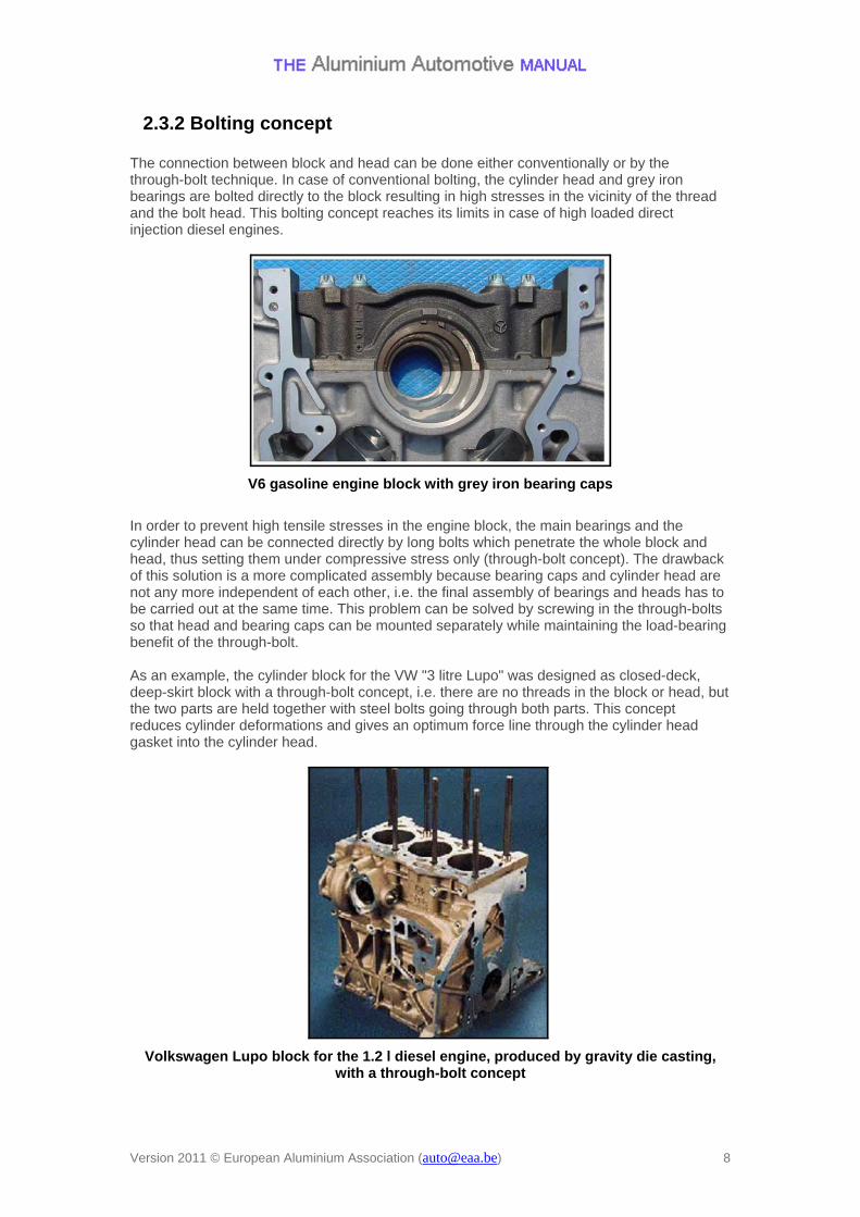
Ladder frame produced by high pressure die casting
Source: Tielkes u.a. Ford/MTZ
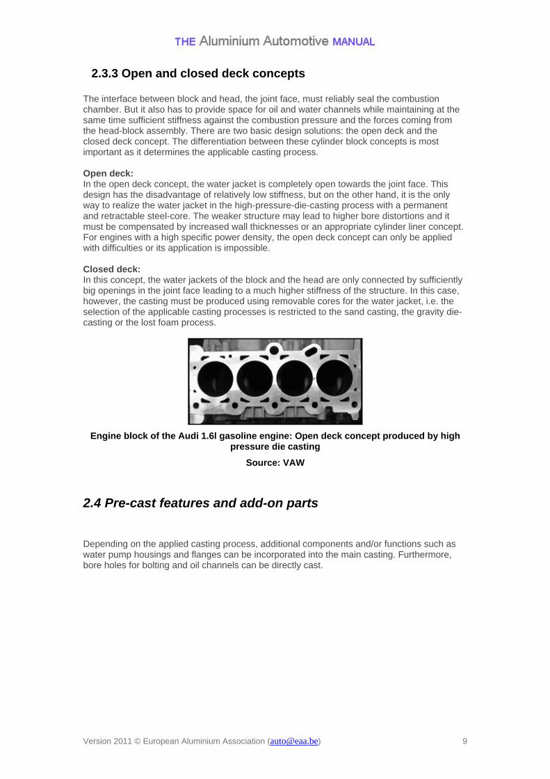
High pressure die cast Volvo in-line 5 cylinder diesel block with bedplate and cast-in grey cast iron liners (Source: KS ATAG)
Version 2011 © European Aluminium Association ([email protected]) 7
2.3.2 Bolting concept The connection between block and head can be done either conventionally or by the through-bolt technique. In case of conventional bolting, the cylinder head and grey iron bearings are bolted directly to the block resulting in high stresses in the vicinity of the thread and the bolt head. This bolting concept reaches its limits in case of high loaded direct injection diesel engines.
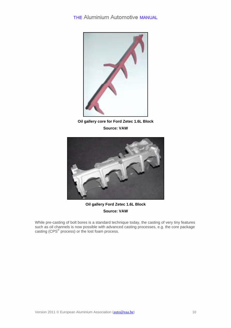
V6 gasoline engine block with grey iron bearing caps
In order to prevent high tensile stresses in the engine block, the main bearings and the cylinder head can be connected directly by long bolts which penetrate the whole block and head, thus setting them under compressive stress only (through-bolt concept). The drawback of this solution is a more complicated assembly because bearing caps and cylinder head are not any more independent of each other, i.e. the final assembly of bearings and heads has to be carried out at the same time. This problem can be solved by screwing in the through-bolts so that head and bearing caps can be mounted separately while maintaining the load-bearing benefit of the through-bolt. As an example, the cylinder block for the VW "3 litre Lupo" was designed as closed-deck, deep-skirt block with a through-bolt concept, i.e. there are no threads in the block or head, but the two parts are held together with steel bolts going through both parts. This concept reduces cylinder deformations and gives an optimum force line through the cylinder head gasket into the cylinder head.
Volkswagen Lupo block for the 1.2 l diesel engine, produced by gravity die casting, with a through-bolt concept
Version 2011 © European Aluminium Association ([email protected]) 8
2.3.3 Open and closed deck concepts The interface between block and head, the joint face, must reliably seal the combustion chamber. But it also has to provide space for oil and water channels while maintaining at the same time sufficient stiffness against the combustion pressure and the forces coming from the head-block assembly. There are two basic design solutions: the open deck and the closed deck concept. The differentiation between these cylinder block concepts is most important as it determines the applicable casting process. Open deck: In the open deck concept, the water jacket is completely open towards the joint face. This design has the disadvantage of relatively low stiffness, but on the other hand, it is the only way to realize the water jacket in the high-pressure-die-casting process with a permanent and retractable steel-core. The weaker structure may lead to higher bore distortions and it must be compensated by increased wall thicknesses or an appropriate cylinder liner concept. For engines with a high specific power density, the open deck concept can only be applied with difficulties or its application is impossible. Closed deck: In this concept, the water jackets of the block and the head are only connected by sufficiently big openings in the joint face leading to a much higher stiffness of the structure. In this case, however, the casting must be produced using removable cores for the water jacket, i.e. the selection of the applicable casting processes is restricted to the sand casting, the gravity die-casting or the lost foam process.
Engine block of the Audi 1.6l gasoline engine: Open deck concept produced by high pressure die casting
Source: VAW
2.4 Pre-cast features and add-on parts Depending on the applied casting process, additional components and/or functions such as water pump housings and flanges can be incorporated into the main casting. Furthermore, bore holes for bolting and oil channels can be directly cast.
Version 2011 © European Aluminium Association ([email protected]) 9
Oil gallery core for Ford Zetec 1.6L Block
Source: VAW
Oil gallery Ford Zetec 1.6L Block
Source: VAW
While pre-casting of bolt bores is a standard technique today, the casting of very tiny features such as oil channels is now possible with advanced casting processes, e.g. the core package casting (CPS® process) or the lost foam process.
Version 2011 © European Aluminium Association ([email protected]) 10
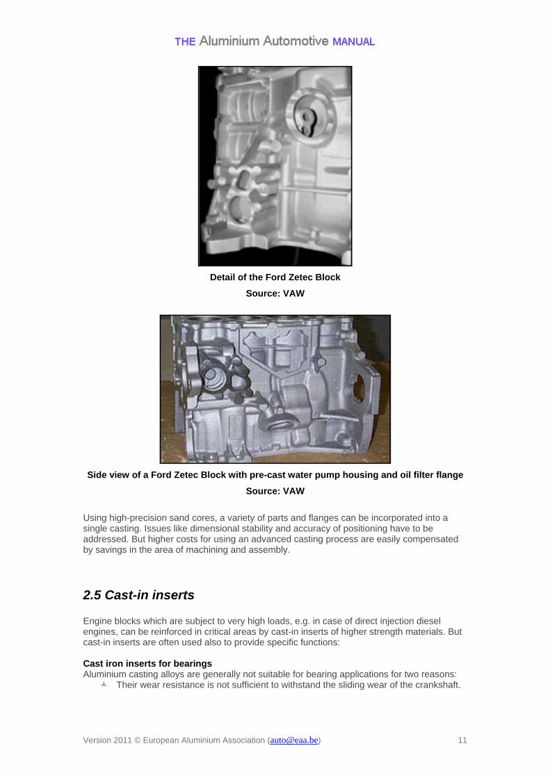
Detail of the Ford Zetec Block
Source: VAW
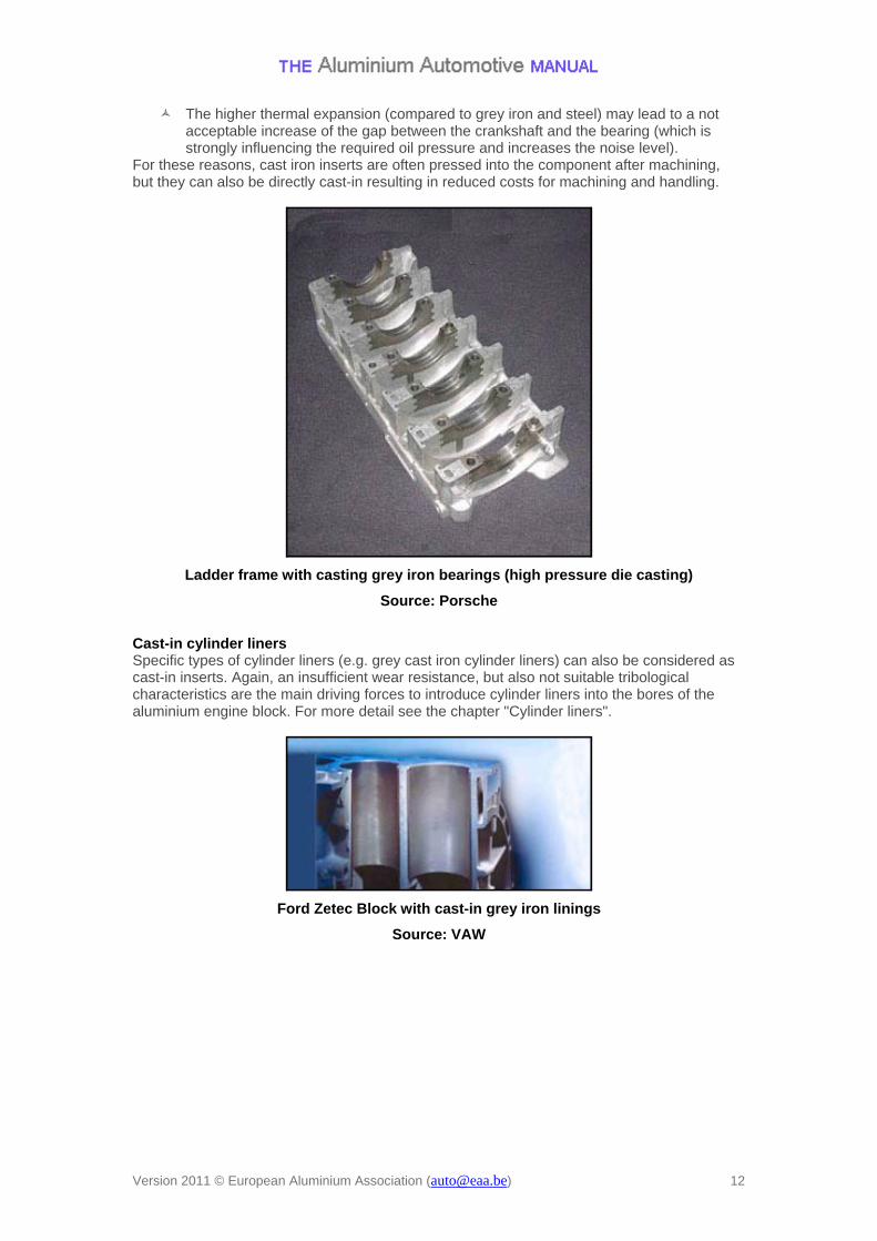
Side view of a Ford Zetec Block with pre-cast water pump housing and oil filter flange
Source: VAW
Using high-precision sand cores, a variety of parts and flanges can be incorporated into a single casting. Issues like dimensional stability and accuracy of positioning have to be addressed. But higher costs for using an advanced casting process are easily compensated by savings in the area of machining and assembly.
2.5 Cast-in inserts Engine blocks which are subject to very high loads, e.g. in case of direct injection diesel engines, can be reinforced in critical areas by cast-in inserts of higher strength materials. But cast-in inserts are often used also to provide specific functions: Cast iron inserts for bearings Aluminium casting alloys are generally not suitable for bearing applications for two reasons:
Their wear resistance is not sufficient to withstand the sliding wear of the crankshaft.
Version 2011 © European Aluminium Association ([email protected]) 11
The higher thermal expansion (compared to grey iron and steel) may lead to a not acceptable increase of the gap between the crankshaft and the bearing (which is strongly influencing the required oil pressure and increases the noise level).
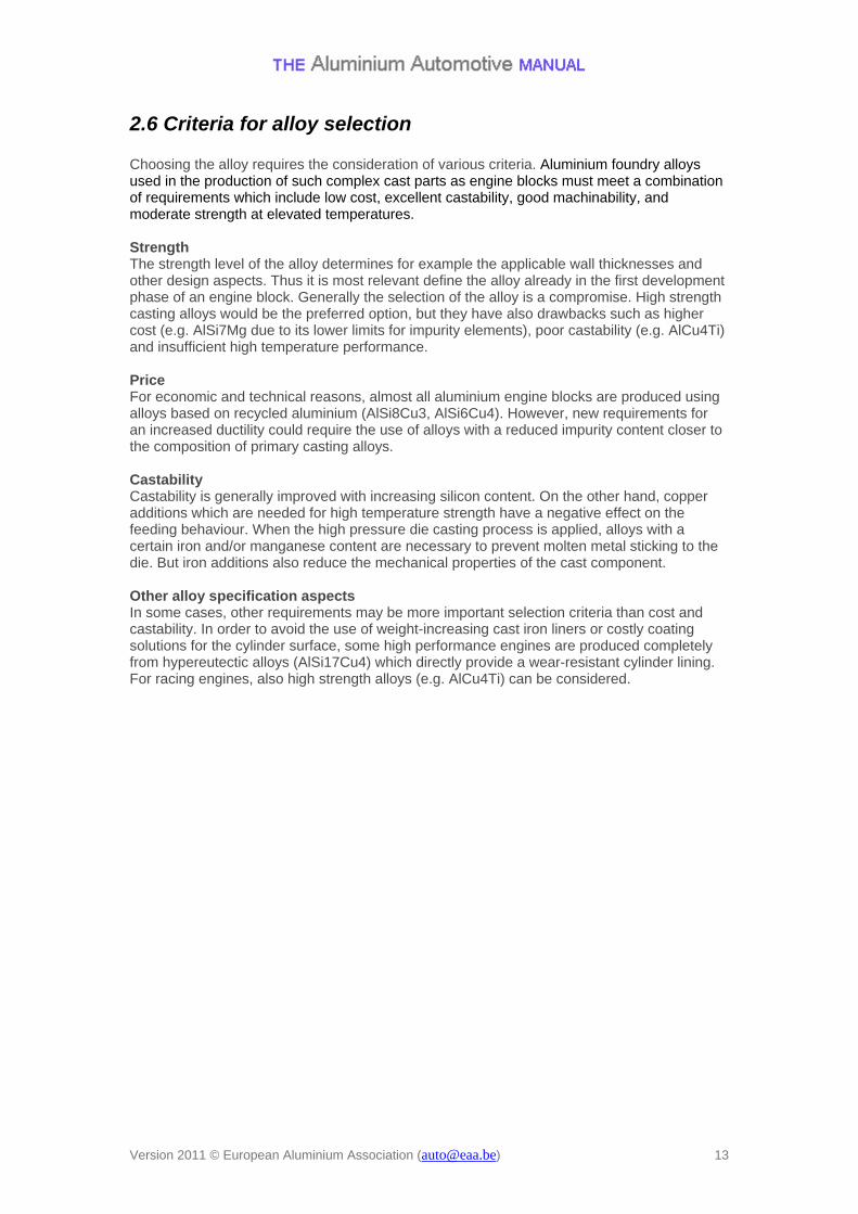
For these reasons, cast iron inserts are often pressed into the component after machining, but they can also be directly cast-in resulting in reduced costs for machining and handling.
Ladder frame with casting grey iron bearings (high pressure die casting)
Source: Porsche
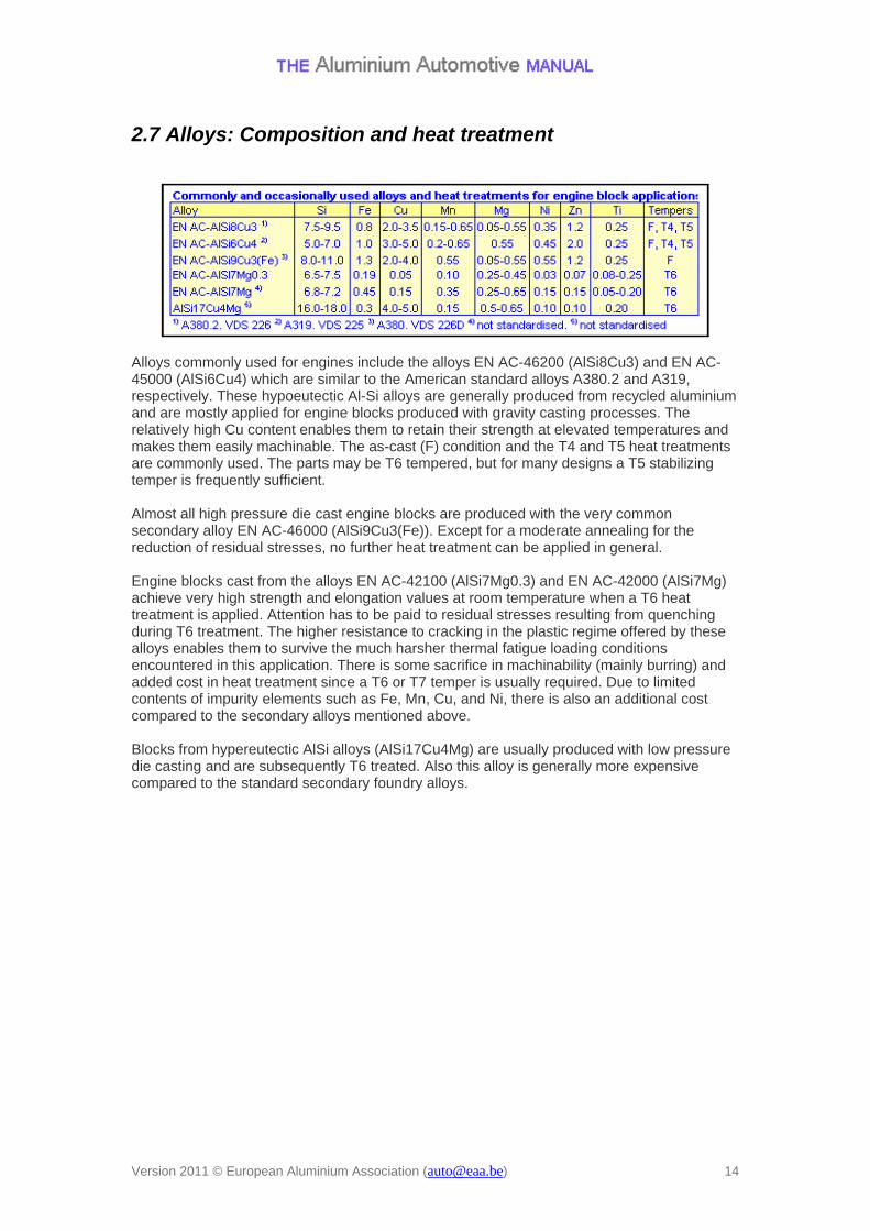
Cast-in cylinder liners Specific types of cylinder liners (e.g. grey cast iron cylinder liners) can also be considered as cast-in inserts. Again, an insufficient wear resistance, but also not suitable tribological characteristics are the main driving forces to introduce cylinder liners into the bores of the aluminium engine block. For more detail see the chapter "Cylinder liners".
Ford Zetec Block with cast-in grey iron linings
Source: VAW
Version 2011 © European Aluminium Association ([email protected]) 12
2.6 Criteria for alloy selection Choosing the alloy requires the consideration of various criteria. Aluminium foundry alloys used in the production of such complex cast parts as engine blocks must meet a combination of requirements which include low cost, excellent castability, good machinability, and moderate strength at elevated temperatures. Strength The strength level of the alloy determines for example the applicable wall thicknesses and other design aspects. Thus it is most relevant define the alloy already in the first development phase of an engine block. Generally the selection of the alloy is a compromise. High strength casting alloys would be the preferred option, but they have also drawbacks such as higher cost (e.g. AlSi7Mg due to its lower limits for impurity elements), poor castability (e.g. AlCu4Ti) and insufficient high temperature performance. Price For economic and technical reasons, almost all aluminium engine blocks are produced using alloys based on recycled aluminium (AlSi8Cu3, AlSi6Cu4). However, new requirements for an increased ductility could require the use of alloys with a reduced impurity content closer to the composition of primary casting alloys. Castability Castability is generally improved with increasing silicon content. On the other hand, copper additions which are needed for high temperature strength have a negative effect on the feeding behaviour. When the high pressure die casting process is applied, alloys with a certain iron and/or manganese content are necessary to prevent molten metal sticking to the die. But iron additions also reduce the mechanical properties of the cast component. Other alloy specification aspects In some cases, other requirements may be more important selection criteria than cost and castability. In order to avoid the use of weight-increasing cast iron liners or costly coating solutions for the cylinder surface, some high performance engines are produced completely from hypereutectic alloys (AlSi17Cu4) which directly provide a wear-resistant cylinder lining. For racing engines, also high strength alloys (e.g. AlCu4Ti) can be considered.
Version 2011 © European Aluminium Association ([email protected]) 13
2.7 Alloys: Composition and heat treatment
Alloys commonly used for engines include the alloys EN AC-46200 (AlSi8Cu3) and EN AC-45000 (AlSi6Cu4) which are similar to the American standard alloys A380.2 and A319, respectively. These hypoeutectic Al-Si alloys are generally produced from recycled aluminium and are mostly applied for engine blocks produced with gravity casting processes. The relatively high Cu content enables them to retain their strength at elevated temperatures and makes them easily machinable. The as-cast (F) condition and the T4 and T5 heat treatments are commonly used. The parts may be T6 tempered, but for many designs a T5 stabilizing temper is frequently sufficient. Almost all high pressure die cast engine blocks are produced with the very common secondary alloy EN AC-46000 (AlSi9Cu3(Fe)). Except for a moderate annealing for the reduction of residual stresses, no further heat treatment can be applied in general. Engine blocks cast from the alloys EN AC-42100 (AlSi7Mg0.3) and EN AC-42000 (AlSi7Mg) achieve very high strength and elongation values at room temperature when a T6 heat treatment is applied. Attention has to be paid to residual stresses resulting from quenching during T6 treatment. The higher resistance to cracking in the plastic regime offered by these alloys enables them to survive the much harsher thermal fatigue loading conditions encountered in this application. There is some sacrifice in machinability (mainly burring) and added cost in heat treatment since a T6 or T7 temper is usually required. Due to limited contents of impurity elements such as Fe, Mn, Cu, and Ni, there is also an additional cost compared to the secondary alloys mentioned above. Blocks from hypereutectic AlSi alloys (AlSi17Cu4Mg) are usually produced with low pressure die casting and are subsequently T6 treated. Also this alloy is generally more expensive compared to the standard secondary foundry alloys.
Version 2011 © European Aluminium Association ([email protected]) 14
2.8 Applicable casting processes For the production of engine blocks, a multitude of casting technologies are applied. From an economic aspect, for mass produced engines, highly automated casting methods using sand moulds (“core package processes”), where the cycle time is not limited by the solidification conditions, are competing with die casting methods where the cycle time is limited.
Version 2011 © European Aluminium Association ([email protected]) 15
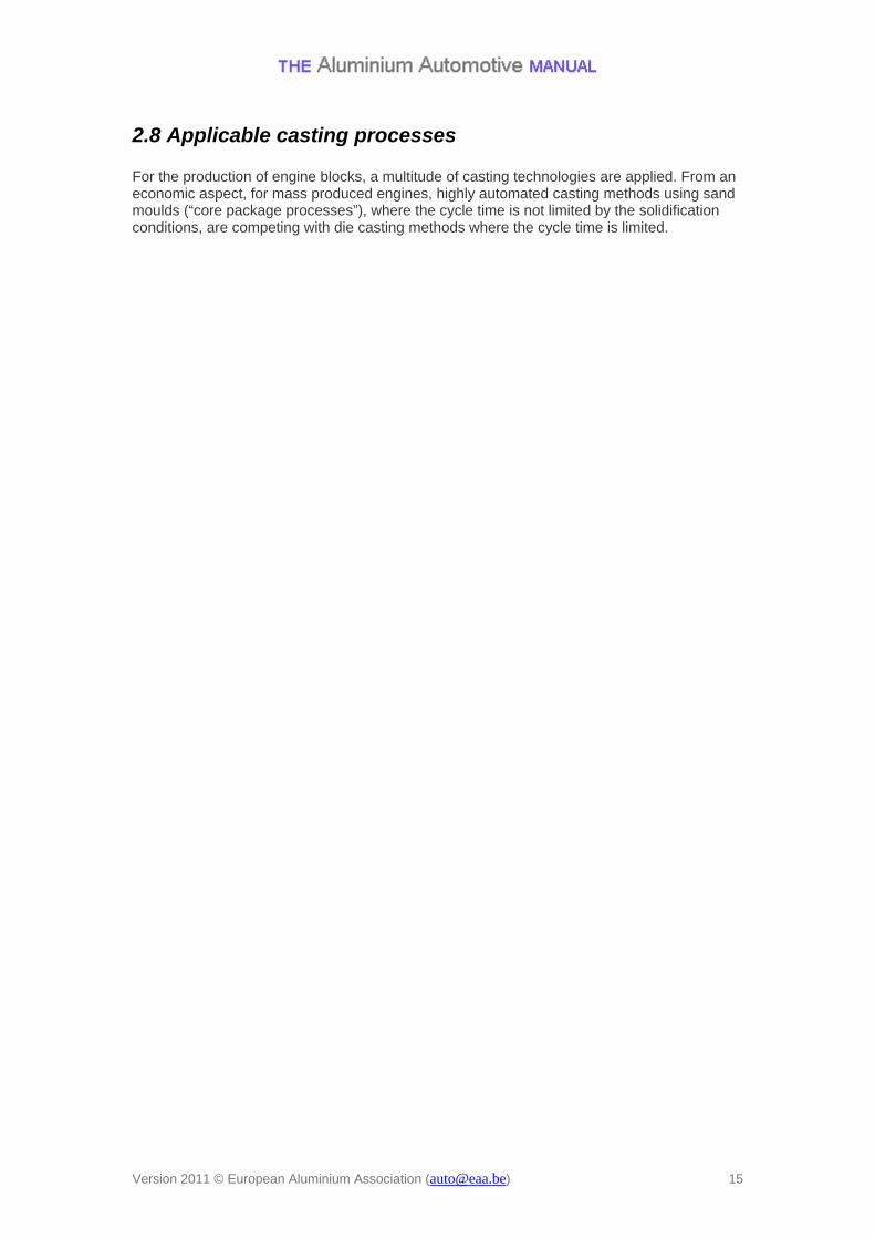
2.8.1 High pressure die casting (HPDC) The majority of the currently produced aluminium engine blocks, in particular three- to six-cylinder in-line engines are produced using the HPDC process for cost-effectiveness. This process is characterized by a high productivity, however, the production volume must be big enough to ensure pay-back of the fairly high tooling investment . The application of a steel mould limits the range of the applicable casting alloys. In principle, the HPDC technology allows only the fabrication of open deck engine block designs. But with a distinctly reduced water jacket depth and co-moulded cylinder bores, the realisation of an open deck variant with a sufficiently rigid cylinder area to meet the requirements of most in-line engines is possible. Also purpose-built sand cores that withstand the high pressures and thermal stresses of the HPDC casting method could be introduced for niche applications (top performance engines in closed deck design), but this option is usually not considered. High pressure die castings are near net-shape parts offering fairly accurate contours and extremely narrow tolerances in terms of dimensions, shape and position. Due to the very turbulent mould filling, a certain amount of casting defects (in particular gas inclusions) is unavoidable. This effect can be compensated by the application of advanced vacuum technologies. Re-feeding possibilities are limited as a result of the early solidification of the gate system, however, in some cases, the local formation of shrinkage cavities can be countered by local squeezers. In thin wall areas, the high solidification rate of high pressure die castings leads to significant strength levels. Engine blocks produced by the conventional HPDC process are usually used in the as-cast state. Heat treatments (e.g. solution heat treatment and artificial age hardening) or welding operations are generally avoided since this would require the application of sophisticated high vacuum technologies.
High pressure die cast deep skirt block of the Daimler A class in-line 4-cylinder engine with cast-in grey iron liners
Source: KS ATAG
The very fast filling of the mould in the HPDC process allows the realisation of extremely thin-walled, shell-like structures. Therefore high pressure die cast engine blocks are generally somewhat lighter than engine blocks produced by other casting techniques. The rigidity deficits of aluminium are compensated by conspicuous ribs, cambering and preferably closed-profile elements.
Version 2011 © European Aluminium Association ([email protected]) 16
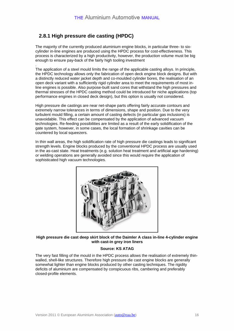
2.8.2 Squeeze casting In contrast to the HPDC process, mould filling in squeeze casting is done rather slowly and in a vertical movement. The die is therefore filled without significant gas inclusions and the components can normally be fully heat treated and welded. Satisfactory die filling and avoidance of oxide inclusions can be ensured by proper process control. But the minimum wall thickness should be slightly higher than in the HPDC process. In practice, the squeeze casting method is mainly used for the infiltration of performs, e.g. for the local integration of aluminium matrix composites as cylinder liners (LOKASIL® technology) into engine blocks.
PORSCHE Boxter opposed-cylinder block halves with LOKASIL® cylinder bore surfaces produced by squeeze casting
Version 2011 © European Aluminium Association ([email protected]) 17
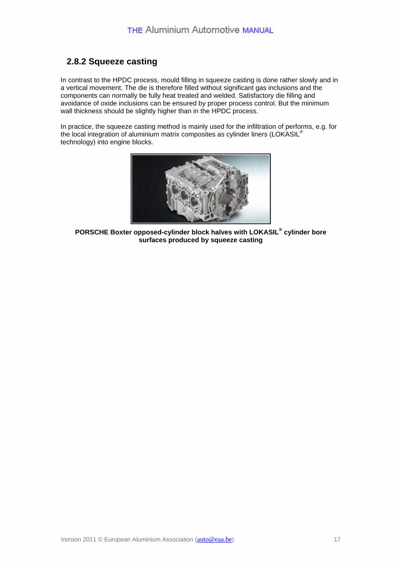
2.8.3 Gravity die casting (GDC) The permanent mold casting process makes use of a permanent steel die into which the aluminium melt is poured under the influence of gravity. Compared to the HPDC process, the complexity of the cast component can be increased by the use of sand cores to form undercuts and complex interior shapes in the casting. The use of water cooling and feeders leads to a directional solidification and hence sound castings with a low amount of defects can be achieved. Filling can be further improved using low pressure filling or the Rotacast® process. Due to the rapid process of solidification, permanent mold castings have a dense, fine-grained structure with good strength characteristics. Together with the possibility of a T5 or T6 heat treatment, the resulting mechanical properties are significantly higher than those which can be achieved with the HPDC process. There are two variants of the permanent mold casting process, the tilting permanent mold process and the low-pressure process. In the tilting process, the die is tilted towards the side of the pouring opening, and then slowly moved back into the upright position as pouring progresses. In the low-pressure process, the melt is subjected to pneumatic pressure in the casting furnace and enters the die against the force of gravity through a rise pipe.
Engine block produce by gravity die casting
Source: Honsel
Version 2011 © European Aluminium Association ([email protected]) 18
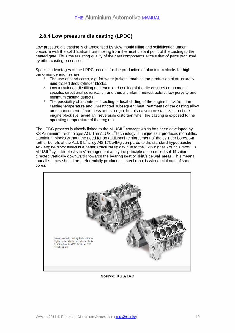
2.8.4 Low pressure die casting (LPDC) Low pressure die casting is characterised by slow mould filling and solidification under pressure with the solidification front moving from the most distant point of the casting to the heated gate. Thus the resulting quality of the cast components excels that of parts produced by other casting processes. Specific advantages of the LPDC process for the production of aluminium blocks for high performance engines are:
The use of sand cores, e.g. for water jackets, enables the production of structurally rigid closed deck cylinder blocks.
Low turbulence die filling and controlled cooling of the die ensures component-specific, directional solidification and thus a uniform microstructure, low porosity and minimum casting defects.
The possibility of a controlled cooling or local chilling of the engine block from the casting temperature and unrestricted subsequent heat treatments of the casting allow an enhancement of hardness and strength, but also a volume stabilization of the engine block (i.e. avoid an irreversible distortion when the casting is exposed to the operating temperature of the engine).
The LPDC process is closely linked to the ALUSIL® concept which has been developed by KS Aluminium-Technologie AG. The ALUSIL® technology is unique as it produces monolithic aluminium blocks without the need for an additional reinforcement of the cylinder bores. An further benefit of the ALUSIL® alloy AlSi17Cu4Mg compared to the standard hypoeutectic AlSi engine block alloys is a better structural rigidity due to the 12% higher Young’s modulus. ALUSIL® cylinder blocks in V arrangement apply the principle of controlled solidification directed vertically downwards towards the bearing seat or skirt/side wall areas. This means that all shapes should be preferentially produced in steel moulds with a minimum of sand cores.
Source: KS ATAG
Version 2011 © European Aluminium Association ([email protected]) 19
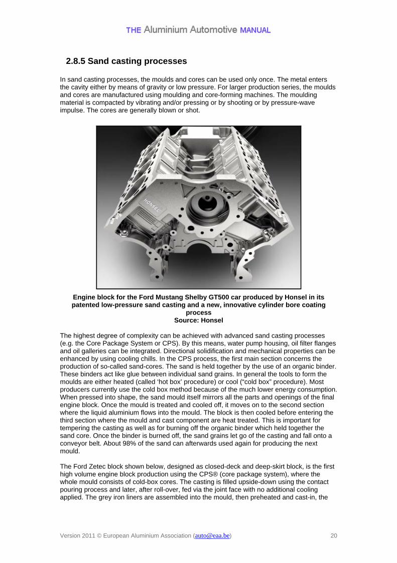
2.8.5 Sand casting processes In sand casting processes, the moulds and cores can be used only once. The metal enters the cavity either by means of gravity or low pressure. For larger production series, the moulds and cores are manufactured using moulding and core-forming machines. The moulding material is compacted by vibrating and/or pressing or by shooting or by pressure-wave impulse. The cores are generally blown or shot.
Engine block for the Ford Mustang Shelby GT500 car produced by Honsel in its patented low-pressure sand casting and a new, innovative cylinder bore coating
process Source: Honsel
The highest degree of complexity can be achieved with advanced sand casting processes (e.g. the Core Package System or CPS). By this means, water pump housing, oil filter flanges and oil galleries can be integrated. Directional solidification and mechanical properties can be enhanced by using cooling chills. In the CPS process, the first main section concerns the production of so-called sand-cores. The sand is held together by the use of an organic binder. These binders act like glue between individual sand grains. In general the tools to form the moulds are either heated (called ‘hot box’ procedure) or cool (“cold box” procedure). Most producers currently use the cold box method because of the much lower energy consumption. When pressed into shape, the sand mould itself mirrors all the parts and openings of the final engine block. Once the mould is treated and cooled off, it moves on to the second section where the liquid aluminium flows into the mould. The block is then cooled before entering the third section where the mould and cast component are heat treated. This is important for tempering the casting as well as for burning off the organic binder which held together the sand core. Once the binder is burned off, the sand grains let go of the casting and fall onto a conveyor belt. About 98% of the sand can afterwards used again for producing the next mould. The Ford Zetec block shown below, designed as closed-deck and deep-skirt block, is the first high volume engine block production using the CPS® (core package system), where the whole mould consists of cold-box cores. The casting is filled upside-down using the contact pouring process and later, after roll-over, fed via the joint face with no additional cooling applied. The grey iron liners are assembled into the mould, then preheated and cast-in, the
Version 2011 © European Aluminium Association ([email protected]) 20
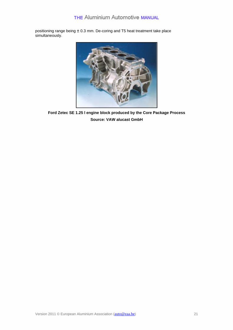
positioning range being ± 0.3 mm. De-coring and T5 heat treatment take place simultaneously.
Ford Zetec SE 1.25 l engine block produced by the Core Package Process
Source: VAW alucast GmbH
Version 2011 © European Aluminium Association ([email protected]) 21
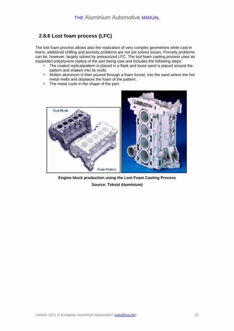
2.8.6 Lost foam process (LFC) The lost foam process allows also the realization of very complex geometries while cast-in liners, additional chilling and porosity problems are not yet solved issues. Porosity problems can be, however, largely solved by pressurized LFC. The lost foam casting process uses an expanded polystyrene replica of the part being cast and includes the following steps:
The coated replica/pattern is placed in a flask and loose sand is placed around the pattern and shaken into its voids.
Molten aluminum is then poured through a foam funnel, into the sand where the hot metal melts and displaces the foam of the pattern.
The metal cools in the shape of the part.
Engine block production using the Lost Foam Casting Process
Source: Teksid Aluminium)
Version 2011 © European Aluminium Association ([email protected]) 22
Version 2011 © European Aluminium Association ([email protected]) 23
2.9 Outlook The strength potential of aluminium has been hardly exploited in gasoline engines today. An optimisation of the common AlSiCu and AlSiMg casting alloys, the available casting processes and of subsequent heat treatments still offers significant growth potential for hardness and strength. Also for diesel engine blocks, the maximum lightweighting potential of aluminium has not yet been reached. The remaining potential in the areas of component design, alloy development and process improvements, but in particular also cylinder surface treatment technologies like plasma sprayed coatings suggest that aluminium will continue its advance in diesel engines. On the other hand, in view of the increasing component loads due to the significantly higher firing pressures in future diesel engines, cast iron in the form of compacted graphite iron (CGI) is again competing with aluminium. Compared to the conventional lamellar graphite cast iron, CGI enables the realisation of smaller cross sections. The nodularity and tensile strength of the material also increases as wall-section decreases. The thermal and damping characteristics of CGI are midway between ductile and gray iron. It is five times more fatigue resistant than aluminium at elevated temperatures, and twice as resistant to metal fatigue as gray iron. Theoretically, a CGI engine block can be fabricated lighter than an aluminum block for equal power densities. Therefore CGI engine blocks are now gaining ground in high performance diesel engines, in particular in V-engines as there is a lot of flexing in the V-area between the cylinders when it is under power. CGI strengthens this physical area considerably. Compared to all-aluminium engine blocks, additional lightweighting can be realized with a composite magnesium-aluminium alloy engine block as produced at BMW’s Landshut plant. The new magnesium-aluminum alloy crankcase for six-cylinder in-line gasoline engines is 24% lighter than a conventional aluminium block. A specific magnesium alloy system and a high pressure die casting (HPDC) process were developed together with the engine’s design. Aluminium inserts incorporating cylinder liners and coolant ducts are used in the engine block. As the magnesium housing shrinks around the aluminium insert, the thermally complex casting process ensures that both components heat up and cool down at precisely the right time during production. The magnesium alloy engine shell never comes into direct contact with coolant water, since the water only flows inside the aluminum cylinder inserts.


![arXiv:1610.02424v2 [cs.AI] 22 Oct 2018arXiv:1610.02424v2 [cs.AI] 22 Oct 2018. a train steam black locomotive is traveling on engine train train coming down a the train engine down](https://img.pdfslide.us/doc/110x75/5f7227610a9e07515a55b9ae/arxiv161002424v2-csai-22-oct-2018-arxiv161002424v2-csai-22-oct-2018-a.jpg)