Embed Size (px)
Citation preview
MICROWA VE ELECTRONICS
APPLICATIONS OF FRACTAL BASED STRUCTURES IN RADAR CROSS SECTION
REDUCTION
A thesis submitted in partial fulfilment of the
requirements for the degree of
DOCTOR OF PHILOSOPHY
by
ANUPAM R. CHANDRAN
Centre for Research in Electromagnetics and Antennas Department of Electronics
Cochin University of Science and Technology Cochin 682 022
India
June 2007

Dedicated to
my parents

CERTIFICATE
This is to certify that the thesis entitled "Applications of Fractal
Based Structures in Radar Cross Section Reduction" is a bona fide
record of the research work carried out by Mr. Anupam R. Chandran
under my supervision in Department of Electronics. Cochin University
of Science and Technology, India. The results embodied in this thesis
or parts of it have not been presented for any other degree.
Cochin-22 28th JUNE 2007
Dr. C. K. Aanandan (Supervising Guide)
Reader Department of Electronics
Cochin University of Science & Technology Cochin - 22

DECLARA TION
I hereby declare that the work presented in this thesis entitled
"Applications of Fractal Based Structures in Radar Cross Section
Reduction" is based on the original work done by me under the
supervision of Dr. C. K. Aanandan in the Department of Electronics,
Cochin University of Science and Technology, India and that no part
thereof has been presented for the award of any other degree.
Cochin-22 30th June 2007 Anupam R. Chandran

ACKNOWLEDGEMENT
I would like to express my deepest sense of gratitude to my supeIVising guide Dr. CK. Aanandan, Reader, Department of Electronics, Cochin University of Science And Technology, for his excellent guidance, valuable suggestions and the constant support I received from him. It has been really a great privilege to work under his guidance.
I am extremely grateful to Dr. K. Vasudevan, Professor and Head, Department of Electronics, CUSAT, for his wholehearted support and interest shown in my work
Let me express my deepest sense of gratitude to Prof. P. Mohanan for his invaluable suggestions and help.
I would like to express sincere thanks to Prof. K.T. Mathew, Prof. P.RS. Pillai and Dr. Tessama Thomas for their support and co-operation.
I am indebted to Dr. T.K. Mathew for fruitful discussions, invaluable help and advice given to me for the successful completion of my work
Special thanks are due to my colleague Mr. Gopikrisna for the timely help and co-operation.
It is with great pleasure I thank my colleagues Mr. Rohith K. Raj, Mr. Shynu S.V, now with Dublin Institute of Technology, Ireland, Ms. Deepti Das Krishna, Mr. Manoj Joseph, Ms. Suma MN, Mr. Deepu V, 11rs. Sreedevi K. Menon, Mr. Gijo Augustin, Ms. Jitha, Ms. Shameena and all the other research scholars of CREMA lab for their valuable help and support.
The encouragement and support received from Mr. AV. Praveen Kumar, Mr. Robin Augustine, Dr. Jaimon Yohannan, Mr. V. Hamsakutty, Mr. Anil Lonappan and Ms. Ullas of M1MR lab and all the research scholars of the Department of Electronics are gratefully acknowledged.
The encouragement I received from Dr. Joe Jacob, Senior lecturer, Newman College, Thodupuzha, kerala India, is greatly acknowledged.

I owe special thanks to Ms. Annie, Mr. Murali, Mr. Russel, Mr. Rajeev, Mr, Siraj, Mr. Ibrahim Kutty and all the other staff of the Department of Electronics for their whole hearted cooperation
I am also grateful to Mr. Suresh, Librarian, Department of Electronics and Dr. Beena, Librarian, Department of Physics for their help and cooperatlon.
During the tenure of my research, the research fellowship was supported by Cochin University of Science and Technology through University JRF. The financial support is gratefully acknowledged.
ANUPAM R. CHANDRAN
Chapter 1
INTRODUCTION
1.1 RADAR CROSS SECfION
1.2 RCS REDUCfION
1.3 FRACfAL
1.4 MOTIVATION
1.5 OUTLINE OF THE PRESENT WORK
1.6 ORGANISATION OF THE THESIS
Chapter 2
REVIEW OF THE PAST WORK
2.1 RADAR CROSS SECfION STUDIES
2.2 FRACfAL ELECfRODYNAMICS
Chapter 3
Contents
2
5
7
14
15
18
21
23
48
METHODOLOGY 55
3.1. OVERVIEW OF RCSMEASUREMENT SYSTEMS 57
3.2. MAJOR FACILITIES USED IN RCS MEASUREMENTS 59
3.2.1. Anechoic Chamber
3.2.2. Network Analyzer
3.2.3. Target Positioner And Controller
59
60
61
3.3 MEASUREMENT TEO-INIQUES 61
3.3.1. Arch Method 63
3.4 DESIGN AND FABRICATION OF FRACfAL BASED 64
METALLODIELECfRICSTRUCfURES
3.5 FLAT PLATES LOADED WITH METALLO-DIELECfRIC 65
STRUCTURES
3.5.1 Metallo-Dielectric Structure Based on Various 66
Iterated Stages of Sierpinski Carpet Fractal Geometry
3.5.2 Structures Based on the Third Iterated Stage of 68
Sierpinski Carpet Fractal Geometry with Generators
of Different Shapes
3.5.3 Sierpinski Gasket Based Metallisation 70
3.5.4 Sierpinski Carpet Fractal Geometries With 71
Varying Lacunarity
3.5.5 Effect of Loading Superstrates 73
3.6 3D STRUCTURES 75
3.6.1 Cylinder 75
3.6.2 Dihedral corner reflector 76
3.6.3 Circular cone 77
Chapter 4
EXPERIMENTAL RESULTS 79
4.1 FLAT PLATES LOADED WITH FRACT AL BASED 82
METALLO-DIELECTRICSTRUCTURES
4.1.1 Different Iterated Stages of Sierpinski Carpet Fractal 83
Geometry
4.1.1 Sierpinski carpet with different patch shapes 89
4.1.2.1 Cross 89
4.1.2.2 Octagonal 91
4.1.2.3 Hexagonal 93
4.1.2.4 Circle 98
4.1.2.5 Diamond 101

4.1.2.6 Purina Square 103
4.1.2.7 Star 105
4.1.2.8 Cross bar fractal tree 108
4.1.2.9 Sierpinski carpet array 110
4.1.3 Sierpinski gasket based metallo-dielectric structure 112
4.2 EFFECT OF LOADING SUPERSTRATES 115
4.2.1 Superstrate loading on Sierpinski carpet fractal geometry 116
4.2.2 Superstrate loading on Sierpinski gasket fractal geometry 118
4.3 FRACTAL GEOMETRIES WITH VARYINGLACUNARITY 120
4.4 RCS REDUCTION OF 3D STRUCTURES 125
4.4.1 Metallic Cylinder 125
4.4.2 Dihedral Corner Reflector 134
4.4.3 Circular Cone 163
Chapter 5
SIMULATION STUDIESAND ANALYSIS 167
5.1 BACKSCATTERING CHARACTERISTICS OF STRUCTURES 169
WITH PATCHES OF DIFFERENT SHAPES
5.2 SIMULATED RESULTS 171
5.3 RCS ENHANCEMENT OF DIHEDRAL CORNER REFLECTOR 180
5.4 EFFECT OF SUPERSTRATE LOADING 186
5.5 EFFECT OF DIELECfRIC CONSTANT 187
Chapter 6
CONCLUSIONS 189
6.1 INFERENCES FROM EXPERIMENTAL INVESTIGATIONS 191
6.1.1 Fractal Based Metallo-Dielectric Structures Loaded Flat 191
Plate

6.1.2 Experiments with 3D structures 193
6.2 CONCLUSIONS FROM SIMULATION STUDIES AND ANALYSIS 195
6.3 SCOPE FOR FURTHER WORK IN THIS FIELD
Appendix-l
DESIGN OF ABANDPN)S FILTER USING CANTOR BAR
BN)ED MET ALL()' DIE LECTRlC STRUCTURE
Appendix-2
DEVELOPMENT OF AN RCS MEN)UREMENT FAOUTY AND
ITS AUTOMATION
REFERENCES
INDEX
LIST OF PUBLICATIONS OF THE AUTHOR
RESUME OF THE AUTHOR
195
197
209
217
239
242
245

Chapter 1
INTRODUCTION
The history of radar dates back to the experiments of Heinrich
Hertz in late 1880s, but the serious development of the radar equipment
began in the middle 1930s simultaneously in several countries. The tenn
RADAR stands for Radio Detection and Ranging and is coined during the
World War II, when tremendous strides were made both in theory and
practice of radar technology. Nowadays, radars are built in a wide range of
sophistications, both in military and civilian applications.
Radar detects objects and locates them in range and angle, by
transmitting electromagnetic waves of known wavefonn. These waves are
reflected from the objects in space, and a portion of the wave energy
comes back towards the radar. The radar reads this returned signal and
analyzes it. This signal can be processed to detennine many properties of
the original object that the wave reflected off. Thus the location of the
object (distance and angular position) as well as its velocity can be
obtained by analyzing the returning signal.
A functional radar system consists of four basic elements. These
are transmitter, antenna, receiver and an indicator. The transmitter
produces radio frequency signals which are beamed towards the object
using the antenna. The energy intercepted by the object is scattered in all
directions. The scattered energy in a particular direction depends on the
size, shape and composition of the obstacle as well as the frequency and
2 Chapter 1
polarization of the incident wave. The energy scattered in the direction of
the receiver is tenned as 'echo' which is collected by the antenna and
processed by the receiver. The target infonnation is then displayed on the
indicator.
In principle, a radar can operate in any frequency, but due to
reasons like propagation effects, availability of components, target
scattering characteristics, antenna size and angular resolution requirements,
the frequency of operation is limited. Eventhough the electromagnetic
spectrum in the frequency range of 3 "MHz to 300 GHz is suitable for
radar operation, the largest number of operational radars fall within the
microwave frequency range.
1.1 RADAR CROSS SECtION
Radar cross section (Res) is a measure of the target's ability to
reflect the radar signals in the direction of the radar receiver. Res is a
characteristic of the particular target and is a measure of its size as seen by
the radar. Res is also a function of frequency, polarization, target
configuration and orientation with respect to the incident field. The basis
for the design and operation of dynamic Res test ranges is the radar range
equation. The radar range equation shows how the received power is
influenced by the Res of the target and other parameters. The radar
equation for free space propagation is given by
p = P'G(G,A?a-, (47r Y R4

Introduction
Where
Pr = received power
Pt = transmitted power
Gt, Gr = transmitting and receiving antenna gains
A. = operating wavelength
R = range from radar to target
and a = Res of the target
3
The power reflected or scattered by a target is the product of its effective
area and the incident power density. In general the 'area' is called
scattering cross section of the target. For directions back towards the
radar, it is called 'backscattering cross section' or the 'Radar Cross Section'.
The scattering cross section is not a constant. It is an angular dependent
property of the target. The far field Res does not vary with changes in
range. Although Res is defined in tenus of area, it has no general
relationship with the physical area of the object. RCS can be expressed as
cr=4Jr
Where E 5 and Hs are the scattered electric and magnetic fields and E i and
Hi are the incident electric and magnetic fields respectively. The unit of
cross section is usually given in square meters. Due to the large variation in
RCS pattern from one aspect angle to another, it is convenient to display
the RCS in logarithmic form. The unit commonly used is decibel over a
square meter or dBsm i.e.
4 Chapter 1
Res (dBsm) = 10 10glO cr
Res of a target will have a wide vanatlon, if the illuminating
electromagnetic wave has got a wide range of frequencies. The variation of
Res with frequency is classified into three regions, depending on the size
of the object. In the first region, the target dimensions are small compared
to wavelength. This is called the Rayleigh region and Res is proportional
to the fourth power of frequency. In the second region, the target
dimensions are approximately equal to the wavelength. This region is
known as the resonance region. In the third region, the object dimensions
are much larger than the wavelength. This region is called the optical
reglOn.
The knowledge of Res characteristics of some simple targets is
very important in Res measurement and analysis of complex targets.
Complex targets such as missiles, ships, aircrafts etc. can be described as
collections of relatively simple shapes like spheres, flat plates, cylinders,
cones and corner reflectors. In measuring the Res of complicated objects,
the measurements are often calibrated by comparing the echo levels of the
test objects with those of the calibration target. As the echo strength of the
calibration target must be known with high degree of accuracy, the
calibration target is always a simple one.
A practical justification for Res measurements is that it is an
incentive to develop products that satisfy Res requirements in addition to
the more usual requirements of mission, range and payload. Res
measurements are necessary to verify anticipated performance as well as to
Introduction 5
evaluate design approaches. In addition, these measurements are
important for the evaluation of microwave absorbers.
The instrumentation for the measurement of Res takes different
fonns. There are simple systems with continuous wave operation
configured from conventional microwave components and standard
receivers and transmitters. Modem network analyzers and frequency
synthesizers have greatly expanded the Res measurement facility. The
transfonnation techniques like frequency domain to time domain available
in most modem network analyzer systems further increased speed,
accuracy and convenience. The study of Radar Cross Section and its
reduction is of great importance in modem communication, and defense
applications.
1.2 RCS REDUCTION
Reduction of Radar Cross Section is a method for increasing the
swvivability by reducing the detectability of objects of strategic
importance like aeroplanes, rockets, missiles etc. There are four basic
methods for reducing the Res of a target. They are:
~ shaping of targets
~ use of radar absorbing materials
~ passive cancellation
~ active cancellation

6 Chapter 1
Each of these techniques adopts different philosophic approaches
and exploits different aspects of the encounter between radar and the
object.
In the shaping technique, the target surfaces and edges are
reoriented or reshaped to deflect the incident wave away from the radar.
But this cannot be done for all viewing angles, since a reduction at one
viewing angle is usually accompanied by an enhancement at another. For
structures such as ships and ground vehicles, internal trihedral and
dihedral corners can be avoided by bringing intersecting surfaces together
at obtuse or acute angles. The disadvantage of shaping is that it can be
made only at the engineering design phase of the target.
Radar absorbing material (RMv1) reduces the energy reflected back
to the radar by absorbing electromagnetic energy through a kind of Ohmic
loss mechanism in which electromagnetic energy is converted to heat
energy. At microwave frequencies, the loss is due to the finite conductivity
of the material and the friction experienced by the molecules in attempting
to follow the alternating fields of an impressed wave. Early absorbers used
carbon as the basic material. But they are too bulky and fragile in
operational environments. Magnetic absorbers are widely used for
operational systems and the loss mechanism is due to a magnetic dipole
moment. Magnetic absorbers offer the advantage of compactness even
though they are heavy.
The basic concept of passive cancellation (also known as impedance
loading) is to introduce an echo source whose amplitude and phase can be
Introduction 7
adjusted so as to cancel the activity of another source. However the
reduction caused for one frequency rapidly disappears as the frequency is
changed. Consequently passive cancellation has been discarded as a useful
Res reduction technique.
In active cancellation method, electromagnetic waves of proper
amplitude and phase are emitted from the target so as to cancel the
reflected wave. For this, the target must sense the angle of arrival,
intensity, frequency and waveform of the incident energy. This method is
not widely used because of the complexity of the system design.
RCS reduction involves a lot of compromises, in which advantages
are balanced against disadvantages. The requirement for reduced RCS
conflicts with the conventional target structures. The final system design is
a compromise which increases cost of the overall system. Reduced
payload, added weight, and increased maintenance are other penalties of
Res reduction.
Reduction of radar cross section using fractal based structures is
ruscussed in this thesis.
1.3 FRACfAL
Mandelbrot introduced the term 'fractal' (from the Latin jraaus,
meaning 'broken) in 1975, to characterize spatial or temporal
phenomena that are continuous but not differentiable. Unlike more
familiar Euclidean constructs, every attempt to split a fractal into smaller
pieces results in the resolution of more structure.

8 Chapter J
A fractal is a rough or fragmented geometric shape that can be
subdivided in parts, each of which is (at least approximatel0 a reduced-size
copy of the whole. Fractal structures are of infinite complexity with a self
similar natw-e. W'hat this means is that as the structure is zoomed in upon,
the structure repeats. There never is a point where the fundamental
building blocks are found. This is because the building blocks themselves
have the same form as the original object with infinite complexity in each
one. Euclidean structures have whole number dimensions, while fractal
structures have fractional dimensions. Fractal geometries have been used
previously to characterize unique occurrences in nature that were difficult
to define with Euclidean geometries, including the length of coasdines, the
density of clouds, and the branching of tress. Therefore, there aroused a
need for a geometty that handles these complex situations better than
Euclidean geometty.
An example of fractal geometty found in nature can be seen in a
fem, s'flown in me figure \.
Figure t Fern, a fmetal geometry found in nature
Introduction 9
The entire frond has the same structure as each branch. If the
individual branches are zoomed in upon, it is quite conceivable to imagine
this as a completely separate frond with branches of its own.
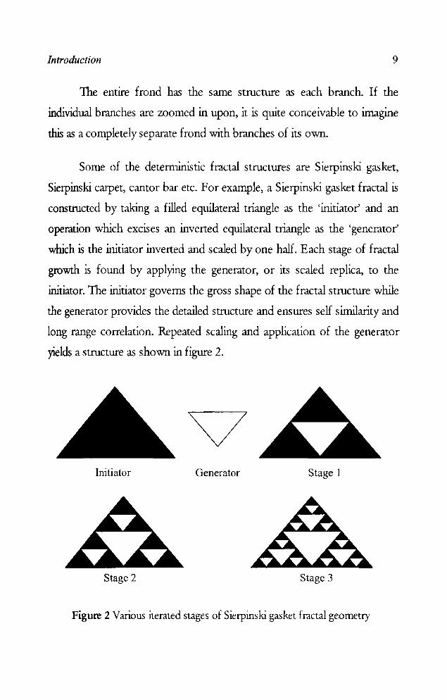
Some of the deterministic fractal structures are Sierpinski gasket,
Sierpinski carpet, cantor bar etc. For example, a Sierpinski gasket fractal is
constructed by taking a filled equilateral triangle as the 'initiator' and an
operation which excises an inverted equilateral triangle as the 'generator'
which is the initiator inverted and scaled by one half. Each stage of fractal
growth is found by applying the generator, or its scaled replica, to the
initiator. The initiator governs the gross shape of the fractal structure while
the generator provides the detailed structure and ensures self similarity and
long range correlation. Repeated scaling and application of the generator
yields a structure as shovm in figure 2.
Initiator Generator Stage 1
Stage 2 Stage 3
Figure 2 Various iterated stages of Sierpinski gasket fractal geometry

10 Chapter 1
Different iterated stages of Sierpinski carpet are shown in figure 3
which is constructed using generator as a small filled square of size 1/3 rd
of the initiator.
Initiator Generator
• • • • • • • •
(a) (b)
• • • • • • • • • ••••••••• • • • • • • • • • • • • • • • ••• • •• • • • • • • • • • • • • • • • ••••••••• • • • • • • • • •
(c) (d)
Figure 3 Different Iterated stages of Sierpinski carpet geometry (a) Stage 1 (b) Stage 2 (c) Stage 3 (d) Stage 4
Similarly, the Cantor bar is formed by a line segment whose 1I3n:1
position from the middle is repeatedly removed. In this case the initiator is
defined as a line segment of lUlit length and the generator is defined as
excising line segment of length one-third. The bar is formed by repeated
application of the generator and its scaled replica to the middle third of the

Introduction 11
initiator or the previous stage of growth. When the thickness of the Cantor
bar becomes va.nishingly small, the resultant fractal becomes Cantor dust.
The growth of Cantor bar fractal geometry is shown in figure 4.
initiator
fPUator
+
11 11 11 Figure 4 Gromh of Cantor bar fractal
In fractal analysis, the Euclidean concept of 'length' is viewed as a
process. 1his process is characterized by a constant parameter D known. as
the fractal (or fractional) dimension. The fractal dimension can be viewed
as a relative measure of complexity, or as an index of the scale-dependency
of a pattern. The fractal dimension is a summary statistic measuring overall
'complexity'.
Dimension of a geometry can be defined in several ways, most of
these often lead to the same number, even though not necessarily. Some
examples are topological dimension, Euclidean dimension, self-similarity
dimension and Hausdorff dimension. Some of these are special forms of
Mandelbrot's definition of the fractal dimension. However, the most easily
Wlderstood definition is for self-similarity dimension. A self-similar set is
one that consists of scaled down. copies of itself. To obtain this value, the
geometry is divided into scaled down., but identical copies of itself. If there

12 Chapter 1
are n such copies of the original geometry scaled down by a fraction f, the
similarity dimension D is defined as:
D = logn
log(~ ) D = log (number of self similar pieces)/log (magnification factor)
For example, a square can be divided into 4 copies of 1h scale, 9 copies of
1/3 scale, 16 copies of 1,4 scale, or rf. copies of 1/ n scale. Substituting in the
above fonnula, the dimension of the geometry is ascertained to be 2.
Similarly we can decompose a cube into nl self similar pieces of l/n with a
dimension of 3. The same approach can be followed for detennining the
dimension of fractal geometries.
Another property associated with fractal geometnes include
lacunarity. Lacunarity is a tenn coined to express the nature of the area of
the fractal having hollow spaces ("gappiness") [151]. The concept of
'lacunarity' was introduced by Mandelbrot [150] as one of the geometric
parameters to characterise fractal. A fractal is 'lacunar' if its gaps tend to be
large, in the sense that they include large intervals, while fractals with small
gaps have smalllacunarity. Highly lacunar fractals are those which are very
inhomogeneous and far from being translationally invariant, while fractals
of low lacunarity are more homogenous and approach translational
invariance. There can be several fractals with the same dimensionality but
different lacunarities, reflecting that the eliminated areas are scanered
differently. Lacunarity gives an idea of the way in which it is filled or the
texture of the set while fractal dimension gives a measure of how much
space is filled by the set [170].
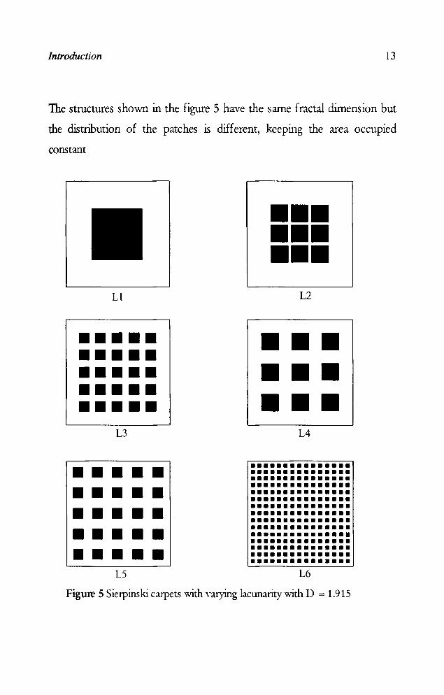
Introduction 13
The structures shown in the figure 5 have the same fractal dimension but
the distribution of the patches is different, keeping the area occupied
constant
Lt
••••• ••••• ••••• ••••• ••••• L3
••••• ••••• ••••• ••••• ••••• L5
111111 111111 111111
L2
111111 111111 111111
L4
••• •• • • ••• • • ••• • • ••• • • ••• • • ••• • • ••• • • • •• • • ••• • • ••• • • • •• • • ••• • • ••• • • • ••• • •• •••• • •• L6
•
Figure 5 Sierpinski carpets with varying lacunarity with D = 1.915
14 Chapter J
1.4 MOTIVATION
A complex target can be represented as collection of basic target
elements like flat plates, corner reflectors, cones and spheroids etc. It is
convenient to isolate the dominant sources in target echo and fix our
attention on a limited number of individual elements instead of composite
target. Flat plates and corner reflectors are the major scattering centres in
the complex target structures. RCS reduction of these scattering centres is
the major concern to the design of targets invisible to radar's eye. The
dominant scattering centers of the targets can be covered with fractal
based metallo-dielectric structures with proper parameters, thereby
reducing the RCS. These structures do not offer any air resistance because
the metallisations is in the same plane as the dielectric sheet. Multipath
intederence from building surfaces is a problem familiar to urban 1V
reception. It is a serious problem for air traffic control systems at airports
due to intederence from hanger walls near airport runways. An approach
to design hanger walls with these surfaces can eliminates unwanted
reflections.
In this thesis, the effect of embedding fractal structures on flat
plates, cylinders, dihedral corners and circular cones is investigated. It is
observed that this technique offers a good amount of reduction in the RCS
of these targets.

Introduction 15
1.5 OUTLINE OF THE PRESENT WORK
The scattering property of a periodic structure depends on the
frequency of the electromagnetic wave as well as the angle of incidence. By
properly selecting the periodicity, one can achieve nurumum
reflection/transmission at certain frequencies and angles of incidence.
Thus the structure becomes 'frequency selective'. By properly combining
different layers of the periodic surfaces, it is possible to obtain the
frequency selective property for a wide range of angles of incidence. These
structures find applications in electromagnetics as frequency selective
surfaces (FSS). They can be used as radomes, frequency scanned gratings,
sub reflectors for multifrequencyantenna systems.
An FSS backed by a ground plane can be used for reducing the
RCS of a target. These structures which can give selective reflection can be
used to reduce unwanted reflection which may interrupt other
communication systems. Development of frequency selective surfaces has
wide range of applications in communication and radar systems. For
example, communication between the aircraft and the terminal buildings is
affected by unwanted reflections from nearby structures such as walls of a
building.
Specular reflections from conducting surfaces can be eliminated by
corrugations of proper period and depth. These corrugations can be of any
shape like saw tooth, rectangular or fin. O:mugations on a conducting
surface with proper parameters can be applied to targets to divert the
power of an incident electromagnetic wave away from the radar and
16 Chapter 1
thereby reduce the Ra;. However, corrugated surfaces on a metallic plate
are heavy and bulky and its fabrication is a tedious and time consuming
task A strip grating, made by etching thin periodic metallic strips on a
dielectric sheet (metallo-dielectric structure) placed over a conducting
plane, shows similar effects of cOIrugated surface and is called as Simulated
Corrugated Surface (Sa;) [132]. Corrugations and SCS have the property
of eliminating specular reflections obeying the principle of Bragg
scattering. An important advantage of sa; over corrugations is in the ease
of fabrication technique using the photolithographic technique.
The main disadvantage of strip gratings developed earlier is that
eliminations of specular reflection is effective only for limited frequency
range and limited angular range, which impose a constraint on its use in
the design of reflection free surfaces. The use of SCS proved that the
frequency bandwidth and angular range of suppression of specular
reflection can be increased appreciably, when the period of the grating
etched on a dielectric of appropriate thickness satisfies the Bragg
condition, but the reduction in backscattered power obtained is only for a
limited range of frequencies. Reduction of backscattered power is also not
obtainable simultaneously for 1E and TM polarizations of the incident
wave using strip grating. Figure 6 shows the schematic diagram of a
corrugated surface and a reflector backed strip grating.

Introduction
/'
-... i' -....
'- '- '-- '-- '- '- - v
(a) (b)
Figure 6 Schematic diagram of (a) Conugated surface (b) Reflector backed strip grating
r--. k ~~~ .-
lit lit
plar¥! m:tallic plate
17
The present work aims at the reduction of RCS of targets using
metallo-dielectric structures based on fractal geometry. The effect of
loading these structures over a flat plate, cylinder, dihedral corner reflector
and circular cone are investigated. Fractal structures have certain properties
like self similarity and space filling property. So fractal based metallization
on a dielectric substrate backed with a conducting surface can be useful in
reducing the backscattered power simultaneously at different frequency
bands and also with improved bandwidth. Also RCS reduction can be
obtained for both TE and 1M polarization of the incident field over a
large bandwidth for structures that are symmetric.

18 Chapter 1
1.6 ORGANISATION OF THE THESIS
The scheme of the work presented in this thesis is given below.
An exhaustive review of the work done in the field of Radar Guss
Section studies and fractal electrodynamics is presented in chapter 2.
The methodology adopted for the work presented in this thesis is
highlighted in chapter 3. The methods used for the measurements of
monostatic and bistatic RC; are presented.
Chapter 4 highlights the experimental results of the investigations
carried out on the scattering behaviour of flat plate, cylinder, dihedral
corner reflector and circular cone loaded with fractal based metal1o
dielectric structures. The effect of various parameters such as dielectric
thickness, dielectric constant, Shape of metallizations and fractal geometry
are investigated.
In chapter 5, the results of the experimental studies are validated by
analyzing the structures using electromagnetic simulation softwares. The
simulation and experimental results are compared for different cases.
Cnmparisons of the backscattering properties of different structures are
also presented for different frequency bands.
Cnnclusions drawn from the investigations are presented in chapter
6. The scope of future work in this field is also discussed.

Introduction 19
Work done by the author in the related fields is presented in
appendices I and 11. The design of a band pass filter employing metallo -
dielectric structure based on cantor bar fractal geometry is presented as
appendix I. The development of an Arch method for Ra; measurements
and its automation is presented in appendix II.
Chapter 2
REVIEW OF THE PAST WORK IN THE FIELD
Methods for reducing Radar Cross Section (RCS) of objects have been
investigated by many researchers both experimentally and theoretically
for the last so many years. This chapter presents a chronological review
of important research in the fields of RCS studies, RCS reduction
techniques and fractal based scattering and radiating structures. This
chapter is divided into two sections. The first section presents a review
of Res studies, ReS reduction techniques and its measurement
techniques and the studies offractal electrodynamics are reviewed in
the second section.
Review of the past work done in the field 23
2.1 RADAR CROSS SECTION STUDIES
The history of investigations on Radar Cross Section dates back to
the early part of twentieth century. The results of the investigations were
not published until World War H. From the end of the World War II till
the present time, the radar response of specific targets has continued to be
an area of considerable interest to many researchers, and great deal of work
has been reported in the field.
The analysis and measurements on RC; of various objects are
available in open literature [1-4]. Hu [5] had measured the RC; of a dipole
antenna in the VHF range with the input terminals of the dipole shorted.
The experimental results were compared with theoretical values.
w. J. Bow et al [6] presented the computed radar cross section data
for microstrip patch antenna arrays as a function of array size, incident
signal frequency, and anisotropy.
E. H Newman and Forria [7] presented a solution to the problem
of plane wave scattering hy a rectangular microstrip patch on a grounded
dielectric substrate. The model does not include the microstrip feed, and
thus does not include the so-called "antenna mode" component of the
scattering. The solution begins by formulating an electric field integral
equation for the surface current density on the microstrip patch.
D. Pozar [8] envisaged the problem of a rectangular microstrip
antenna printed on a uniaxially anisotropic substrate. The effect of
anisotropyon the resonant frequency and surface wave excitation of the
antenna is considered, and the radar cross section (RC;) of the antenna is
calculated. The RC; calculation includes the effect of the load impedance
(antenna mode scattering). The derivation of the uniaxial Green's function

24 Chapter 2
in spectral form, the associated moment method analysis for the input
impedance and scattering of the microstrip patch, and the expressions for
the far-zone fields of a source on a uniaxial substrate are presented.
D. R Jackson [9] proposed a general formula for an arbitrary
resonant conductive body -within a layered medium, which shows that the
body radar cross section is directly related to the radiation efficiency of the
body.
A Taflove and K. Umashankar [10] presented two disparate
approaches- FDTD and MoM:, the analysis and modeling of realistic
scattering problems using these two methods are summarized and
compared. New results based on these two methods for induced surface
currents and radar cross section are compared for the three dimensional
canonical case of a conducting metal cube illuminated by a plane wave.
D. Colak et al [11] presented a dual series based solution for the
scattering of an H-polarized plane wave from a silted infinite circular
cylinder coated with absorbing material from inside or outside. For both
cases, numerical results are presented for the radar cross section and
comparisons are given for two different realistic absorbing materials.
C -G. Park et al [12] investigated the problem of transverse
magnetic plane wave scattering from a dihedral corner reflector. Using the
mode matching technique, the transmitted and scattered fields are
expressed in the angular spectral domain in terms of radial wave guide
modes.
D. A Edward et al [13] presented the application of variational
techniques to the electromagnetic scattering problem. It has been shown
that these techniques can deal effectively with distorted structures and the
case of onhogonal and nononhogonal distorted dihedrals in some detail.

Review of the past work done in the field 25
Harrison and Heinz [14] had derived a fonnula for the R~ of a
solid wire, tabular and strip chaff of finite conductivity approximating one
half wavelengths or less in length.
In the RC; analysis of coated metal plate by Knop [15], the
thickness of the plate and that of the coating were assumed to be thin, and
the size of the plate was large, so that physical optics approximation could
be used.
Blore [16] had made experimental investigation for the effect of
nose on backscattering R~ of grooves, cone spheres, double backed
cones, double rounded cones and cone spheres.
Rheinstein [17] had carried out several series of rigorous numerical
calculations of the backscatter cross sections of a conducting sphere with a
thin lossless dielectric coating.
Senior [18] reviewed the analytical techniques available for
estimating the backscattering cross section of a metal target with
classification given on the basis of wavelength to dimension of the targets.
Blacksmith et al. [19] reviewed the history of radar cross section
measurement. Gispin and Maffet [20-21] reviewed the R~ measurement
methods for simple and complex shapes, with special attention being
devoted to results rather than derivations of fonnulae.
The conditions of R~ measurement in terms of variations in the
amplitude and phase of the incident field at the target, were discussed by
Kouyoumijian and Petits [22]. A number of minimum range conditions
were listed and discussed. The theoretical and measured data pertaining to
background levels which can be achieved with conventional target
supports were presented by Freeny[23].

26 Chapter 2
Leipa and Senior [24] investigated the scattenng of plane
electromagnetic wave by a metallic sphere loaded with a circumferential
slot in a plane nonnal to the direction of incidence. The slot was assumed
to be of small width and the field scattered in any direction is obtained by
the supetposition of the field diffracted by an unloaded sphere, and the
field radiated by excited slot. Numerical and experimental results of
backscattering were also presented.
O:mmer and Pyron [25] have presented a bibliography of articles
on radar reflectivity and related subjects. The design of an extremely high
range resolution FWCW' X-band radar and Res measurements were
illustrated by Alongi et al. [26]. The primary design objective was to
provide the capability to measure Res of scaled models with a range
resolution equal to a small fraction of the target length. Millin et al. [27]
presented a numerical technique for the determination of scattering cross
section of infinitely long cylinders of arbitrary cross section.
Radar cross section of a rectangular flat plat was investigated by
Ross [28]. The simple phf-iical optics theory was used for predicting the
near specular values of RCS but failed to account for polarization
dependence. The calculations based upon the geometrical theory of
diffraction showed excellent agreement with measured data except on edge
on aspects.
Miller at el. [29] presented the monostatic Res results for straight
wires having lengths of multiple wavelengths. The numerical Res values
obtained from solving the Pocklington's integral equation for induced
current, fall within 1 dB of experimental measurements.
Res of a perfectly conducting sphere coated with a spherically
inhomogeneous dielectric was obtained using the geometrical theory of

Review of the past work done in the field 27
diffraction by Alexopoulos [30]. The result was compared to the second
order approximation obtained by asymptotic theory.
Miller and Morton [31] have studied the RC) of a metal plate with
resonant slot. RCS of a thin plate for near grazing incidence was studied by
Yu [32] with three higher order diffraction techniques.
Rahmat Samii and Mittra [33] employed a new integral equation to
calculate the current distribution on a rectangular plate, when illuminated
by a plane wave. Numerical results were also presented for the RC) of a
plate for different angles of incidences and different dimensions of the
plate.
Lin et al. [34] experimentally and numerically investigated the RCS
of a conducting rectangular plate. The numerical example also included the
edge on incidence where physical optics and geometric theory of
diffraction have failed.
Wier et al. [35] developed a technique for making RC)
measurements over wide frequency bands. The Hewlett-Packard (HP)
automatic network analyzer, which measures the scattering parameters at
discrete frequencies over a band, has been adapted to obtain RC)
measurements. Typically the background clutter, antenna cross coupling
and system errors in the absence of target were reduced by the system
measurement techniques to an equivalent value of -45 dBsm.
Mautz and Harrington [36] presented the computation of radiation
and scattering of electromagnetic fields by electrically large conducting
cylinders using geometrical theory of diffraction for the transverse electric
case. The computation accuracy was checked by comparing the results to
corresponding ones computed by a moment method solution to the H
field integral equation.

28 Chapter 2
An accurate mathematical model for the backscanering from a
loaded dihedral corner has been developed by Corona et al. [37]. This
model employed a generalization of physical optics to loaded surfaces
which takes onto account the lighting of each face by rays diffracted by
edge of other one.
Griesser and Balanis [38] predicted the backscanered cross section
of dihedral corner reflectors which have right, obtuse and acute interior
angles, using the uniform theory of diffraction (UTD) plus an imposed
edge diffraction extension. Multiple reflected and diffracted fields up to
third order were included in the analysis, for both horizontal and venical
polarizations.
Arvas and Sarkar [39] have considered the problem of determining
the RC; of two dimensional structures consisting of both dielectric and
conducting cylinders of arbitrary cross section. Both transverse electric and
transverse magnetic cases are considered. The problem is formulated in a
set of coupled integral equations involving equivalent electric and magnetic
surface currents, radiating in unbounded media.
The low RC; measurement requires careful cancellation of the
background reflections. The large size of the target tends to upset the
background cancellation balance obtained in the absence of the target. So,
when the cross section of the target is large, the target to background cross
section ratio can be made large.
RC; reduction of dihedral corners, which are major scanering
centers in radar signatures of ship and military ground vehicles, was
studied by Knon [40]. A criterion was developed that gives the required
corner angle as a function of RC; reduction desired and electrical size of
corner faces.
Review of the past work done in the field 29
The broadside R~ of a rectangular box was studied by Tsai [41]
using the integral equation technique. Jones and Shumpen [42] presented
the electromagnetic scattering behaviour of a perfectly conducting
infinitesimally thin, spherical shell with circular aperture. The problem was
fonnulated in tenns of E-field integral equation. The calculated values of
surface currents and R~ were presented and discussed for several cases of
interest.
A scheme is presented by J. L. Volakis et al [43] for reducing the
RCS of patch antennas outside their operational band without
compromising gain performance. This is achieved by placing a narrow
resistive strip (distributed loading) around the periphery of the patch which
has minimal effect at the operational frequency of the patch. Results are
presented using a finite element-boundary integral code demonstrating the
effectiveness of this scheme over the traditional method of using lumped
loads.
Keen [44] presented the development of a numerical technique for
calculation of the RCS of any regular shape of corner reflector consisting
of three orthogonal plates. A simple and accurate formula to calculate the
bac~cattered R~ of a perfectly conducting hollow, finite circular cylinder
with closed termination was proposed by Huang [45]. The radiated field
from the cavity region was evaluated via, the Kirchoff approximation and
the reciprocity theorem.
Le Vine [46] presented a solution for the backscatter RCS of
dielectric disks, of arbitrary shape, thickness and dielectric constant. The
result was obtained by employing a Kirchoff type approximation, to obtain
the field inside the disk
30 Chapter 2
The application of the uniform asymptotic theory of diffraction to
obtain an expression for Res of cUlVed plate was presented by Sanyal and
Bhattacharyya [47]. Comparison with experimental results shows good
agreement even for different small and intermediate radii of cUlVature of
the plate.
An asymptotic high frequency estimation of monostatic Res of a
finite planar metallic structure coated with a lossy dielectric was made and
compared with experiments in X band, by Bhattacharyya and Tandon [48].
Rembold [49] reponed the measurement of Res of a long metallic
rod using continuous wave Doppler radar at 60 GHz. The derived
expression for RCS demonstrates good agreement with the measured data.
A continuous wave Res measurement facility in the X band was described
by Bhattacharyya et al. [SO]. The set up was capable of automatically
measuring the monostatic Res over aspect angle ranging from 0 to +or-
1800 for both parallel and perpendicular polarizations. The typical value of
effective isolation between transmitted and received signal was of the order
of 60 dB and dynamic range of 35 dB.
Corona et al. [51] studied the radiation characteristic of a 900
dihedral corner reflector and showed that it can be conveniently used as a
reference target in experimental determination of Res. The nwnerical
model developed using physical optics and image method, has been
improved by taking into aCCOtlllt the rays diffracted by corner edges.
In 1987, Dybdal [52] reviewed the ftmdamentals of Res measurements. The wide bandwidth electronic and digital signals
processing capabilities encouraged the earlier objective of determining the
RCS and have extended to include the developing techniques to distinguish
different types of targets and modifying the target scattering properties.

f. Review of the past work done in the field 31
Achievable accuracy and those factors that limited the accuracy were
discussed.
Lee and Lee [53] calculated the Res of a circular wave guide
tenninated by a perfect electric conductor. Geometrical theory of
diffraction was employed for the rim diffraction and physical optics was
employed for the interior irradiation.
Anderson [54] used the method of physical optics to calculate the
magnitude of the reduction of Res, which result from modest departures
from orthogonality. The theoretical results were compared with
experimental measurements which are found to be in very good
agreement.
Welsh and Link [55] developed two theoretical models for Res
measurements of large targets consisting of multiple independent point
scatterers .
The history of bistatic Res of complex objects was presented by
Glaser [56]. Beginning with the first radars before World War 11, the
discussion proceeds with current experimental and analytical mode ling
methods. Data were presented from experiments on cylinders and missiles.
Youssef [57] presented a srunmary of developments and
verifications of a computer code, for calculating the Res of complex
targets. It is based on physical optics, physical theory of diffraction, ray
tracing, and semi-empirical formulations. Wu [58] evaluated the Res of
arbitrarily shaped homogeneous dielectric body of revolution by surface
integral formulation. Accuracy of the method was verified by good
agreement with the exact solutions for the RC; of a dielectric sphere.
Mitschang and Wang [59] described hybrid methods incorporating
both numerical and high frequency asymptotic techniques for

32 Chapter 2
electromagnetic scattering problems of complex objects. Sarkar and Arvas
[60] have presented an E-field equation for the computation of RC) of
finite composite conducting and lossy inhomogeneous dielectric bodies.
RC) patterns of lossy dihedral corner reflectors were calculated
using a uniform geometrical theory of diffraction for impedance surfaces
by Griesser and Balanis [61]. All terms upto third order reflections and
diffractions were considered for patterns in the principal plane. The
dihedral corners examined have right, obtuse, acute interior angles and
patterns over the entire 3600 azimuthal plane were calculated.
The problem of determination of the fields scattered by an infinite
dielectric cylinder of arbitrary cross section, located at the interface
between two semi-infinite dielectric media was presented by Marx [62].
The derivation of integral equations was given for transverse electric mode,
for dielectric cylinder and for a perfectly conducting cylinder.
Pathak and Burkholder [63] have analysed the problem of high
frequency electromagnetic scattering by open ended waveguide cavities
with an interior termination, via three different approaches, modal, ray and
beam techniques. Typically numerical results based on the different
approaches were presented, and some pros and cons of these approaches
were discussed.
The problem of electromagnetic scattering from a plate with rim
loading for transverse electric (1'£) and transverse magnetic (TIvf) polarizations was examined by Bhattacharyya [64], based on uniform
geometrical theory of diffraction. An attempt was made to estimate the
width of the coating around the edges which gives the same result as the
plate of same size which is uniformly coated. Theoretical results were
presented and discussed.
Review of the past work done in the field 33
Penno et al. [65] examined the scattenng from a perfectly
conducting cube. The results presented were for a cube on the order of 1.5
- 3 wavelengths on edge, which is illuminated at broadside incidence.
Hybrid iterative method was employed, which utilizes an initial
approximation of the surlace currents on the cube faces.
Tice [66] has presented an overview of Res measurement
techniques. In this review, the measurement radar was limited to ground
based radar systems. Targets included operational full scale ships and
aircrafts, full scale aircraft mounted on pylons and scale model of ships in
water.
Choi et al. [67] have investigated the backscattering Res of finite
conducting cones using equivalent current concept based on unifonn
geometrical theory of diffraction. The discrete Fourier transfonn method
was used to calculate the Res of orthogonal and non-orthogonal dihedral
corner reflectors by Shen [68]. The results obtained using the method
compare favourably with measurements and predictions computed using
the method of moments.
The Res of a partially open rectangular box in the resonant region
was investigated by Wang et al. [69]. Two dimensional numerical results
were generated using the method of moment's solution to the electric field
integral equation. The dependence of the resonant behaviour on the box
dimension, aperture size and incident polarization were interpreted in
tenns of the field distribution inside the cavity. Experimental data for a
three dimensional box were also presented. They were consistent with the
two dimensional simulation.
Blejer [70] presented the polarization matrix for a cylinder on a
circular disk using the physical optics approximation. Multiple scattering
34 Chapter 2
between the cylinder and the circular disk groWld plane was obtained by
invoking the image theory, and was expressed as a bistatic return from the
cylinder and its image, due to the image field. Theoretical values were
compared with experimental results.
Goggans and Shumpen [71] presented the RCS of dielectric filled
cavity backed apertures in two dimensional bodies for both 1E and 1M
polarizations. The method of moment technique was employed to solve a
set of combined field integral equations for equivalent induced electric and
magnetic currents on the exterior of the scattering body and associated
aperture.
Baldauf et al. [72] presented a general method for calculating the
Res of three dimensional targets. Following shooting and bOWlcing ray
method, a dense grid of rays was laWlched from the incident direction
towards the target. Each ray was traced according to geometrical optics
theory including the effect of ray tube divergence, polarization and material
reflection coefficient. At the point where the ray exits the target, a physical
optics type integration is performed to obtain the scattered fields. The
theoretical results were in good agreement with measured data.
Mongia et al. [73] reponed the results of precise measurement of
Res of dielectric resonators of cylindrical and rectangular shape at
resonance. The measured results were compared with those predicted by
asymptotic theory.
The monostatic Res spectra of rotating fan array, with tilted metal
blades were investigated by Yang and Bor [74]. The high frequency
theoretical treatment of slowly rotating and electrically large scatterer was
based on the quasi-stationary method with the physical optics / physical
~ of the past work done in the field 35
theory of diffraction technique. The agreement with the theoretical and
experimental results was acceptable.
Trueman et al. [75] investigated the effect of wire antennas on the
;"high frequency Res of aircraft by comparing the Res of strip, cylinder,
(and a rod with and without attached wire.
Mishra et al. [76] presented the precision measurements of Res of
" simple rod and cylinder for all angles of incidence in a plane containing the
long axis of the target. Fully automated Res measurement setup used an
HP series 9000, model 332 instrumentation controller for process control
and data acquisition and processing. HP 8510 Network analyzer system
with HP 8511A frequency converter as receiver front end was used to
determine the scattered field amplitude and phase at many frequencies
from 2 to 18 GHz. The extensive measured Res data were used as a
reference for validating numerical computations.
RillS et al. [77] presented a new and original approach for
computing the Res of complex radar targets, in real time 3-D graphics
workstation. Res of aircrafts were obtained through physical optics (PO),
method of equivalent currents (1v1Eq, physical theory of diffraction (PTO)
and impedance boundary condition (IBq. A graphical processing
approach of an image of the target at the workstation screen was used to
identify the surface of the target visible from the radar viewpoint and
obtain the unit nonnal at each point. The high frequency approximations
to RCS prediction were then easily computed from the knowledge of the
unit nonnal at illuminated surface of the target. This hybrid graphic
electromagnetic computing results in real-time Res prediction for complex
targets.
36 Chapter 2
RCS of rectangular microstrip patch on a lossy biased ferrite
substrate was investigated by Yang et al. [7S], based on a full wave integral
equation fonnulation in conjunction with the method of moments. The
RCS characteristics, especially the resonance behaviour of the patch, with
various biasing conditions were studied and compared to the case of an
unbiased ferrite.
Bincher et al. [79] measured the RC; of a long bar (at X-band) and
a scale model aircraft (at G band) under the quasi plane wave illumination
and cylindrical wave illumination and compared the results.
The RC; of a small circular loop made from YBCO high
temperature superconductor were calculated as a function of applied
magnetic field strength by Cook and Khamas [SO]. It was shown that RC;
is reduced as the magnetic field increases and that effect was more
pronounced as the radiation distance decreases.
The RC; of several bodies proposed by the electromagnetic code
consortium (EMCQ was calculated using transmission line matrix (ILlv.f)
method [S1]. The results were in good agreement with experimental and
moment method solutions, when 1LM was used together with an
appropnate boundary condition and a near to far zone transmission
approach.
Grooves [S2] have proposed an important class of boundary
structures, having alternate areas of conducting and non-conducting
materials, for control and direction of electromagnetic waves incident on
them.
The solution for the problem of a plane wave incident obliquely on
a parallel wire grid, which is backed by a plane conducting surface was

Review of the past work done in the/ield 37
presented by Wait [83]. It was shown that, in certain cases, a resistive wire
grid will absorb the entire incident wave.
The theoretical and experimental results for the reflection and
transmission of unifonn plane electromagnetic waves, nonnally incident
on an ideal strip grating was presented by Primich [84]. The theory was
based on the variational method, and measurements were made at normal
incidence in a parallel plate region operating in 8 - 10 cm wavelength
range.
Tadaka and Shiniji [85] presented a diffraction grating which was a
new version of microwave passive repeater developed to improve the
transmission qualities of links utilizing mountain diffraction. Principles and
characteristics of diffraction gratings were given with test results.
Sigelmann [86] has studied the surlace wave modes in a dielectric
slab covered by a periodically sloned conducting plane. Sampling and
variational methods were used to obtain surlace wave modes.
Jacobson [87] described an analytical and experimental investigation
of practical, two dimensional periodically modulated slow wave structures.
The structure was a dielectric slab covered on one side by a perfectly
conducting ground plane and the other side by perfectly conducting strips
perpendicular to the direction of propagation.
Integral equations for currents induced on an infinite perfectly
conducting grating for plane wave illumination were presented by Green
[88~ These integral equations were approximated by matrix equations,
which were readily solved for currents. From these currents the strengths
of the grating modes were obtained.
A numerical solution for the problem of scattering of a plane wave
by a dielectric sheet with an embedded periodic array of conducting strips

38 Chapter 2
was presented by Lee [89]. The solution to the problem of scattering of
plane wave by an infinite periodic array of thin conductors on a dielectric
slab was formulated by Montgomery [90]. Numerical results were
presented with experimental data.
Montgomery [91] analyzed the scattering of an infinite periodic
array of microstrip disks on a dielectric sheet using Galerkin solution of
vector integral equation. In 1979, he studied [92] the solutions of TE and
1M scattering for an infinite array of multiple parallel strips. The solution
was found using the penurbation form of modified residue calculus
technique. Numerical results were presented and discussed.
By using microwave models of optical gratings, Tamir et al. [93-95]
realized dielectric grating with asymmetric triangular or trapezoidal profiles
that exhibit beam coupling efficiencies. The behaviour of leaky modes
along microwave gratings show that, Bragg scattering approach provides
simple design criteria for blazed dielectric gratings and broad band high
efficient optical beam coupling devices.
Petit [96] presented the electromagnetic theory of plane grating, in
which the integral methods and differential methods were studied in
greater depth.
Kalhor and Ilyas [97] analyzed the problem of scattenng of
electromagnetic waves by periodic conducting cylinders embedded in a
dielectric slab backed by a plane reflector using the integral equation
technique. The results were compared with the limited numerical results
available in the literature and indicate excellent agreement.
A method of analysis of strip gratings with more than one
conducting strip per period was given by Archer [98] and that was then
applied to a periodic twin strip grating with two unequal gaps.

Review of the past work done in the field 39
Fonnulae for ideal and good grating system were given by Xu
Jeadong and Guorui [99]. Some applications of the strip grating systems
such as frequency filter, polarization rotators and impedance transfonners
were introduced and the principle design considerations of impedance
uansfonners were discussed.
Kobayashi [100] investigated the problem of diffraction by a thick
sttip grating with the aid of Wiener-Hopf technique. Kobayashi [101-102]
considered periodic parallel plate grating with dielectric loading, and the
problem was analyzed with the same technique. The Wiener-Hopf
equation was solved by decomposition procedure and then the modified
residue calculus technique (MRCI) was applied to increase the accuracy of
the solution.
Jose and Nair [103] have showed that the gratings can be used to
simulate the effect of rectangular conugations in conducting surfaces. The
perfect blazing of reflector backed thin strip gratings to n = -1 spectral
order for both TE and lM polarizations were compared with corrugated
reflection gratings.
A fast convergent integral equauon solution to the scanenng
problem of TE/lM plane wave by a one dimensional periodic array of
thin metal strips on a dielectric substrate was described by Wu [104].
The development of reflector backed strip gratings exhibiting the
properties like the elimination of specular reflection from a conducting
surface for normal and near normal incidence was reported by Jose et al.
[105]. This was achieved by using self complimentary strip grating which
were not possible using conventional rectangular metallic corrugations.
Kalhor [106] analyzed the scattering of electromagnetic waves from
a dielectric slab loaded with periodic array of conducting strips, using
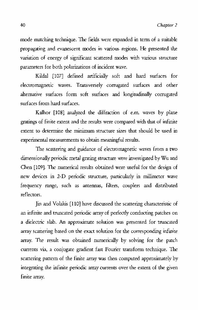
40 Chapter 2
mode matching technique. The fields were expanded in term of a suitable
propagating and evanescent modes in various regions. He presented the
variation of energy of significant scattered modes with various structure
parameters for both polarizations of incident wave.
Kildal [107] defined artificially soft and hard surfaces for
electromagnetic waves. Transversely corrugated surfaces and other
alternative surfaces form soft surfaces and longitudinally corrugated
surfaces from hard surfaces.
Kalhor [108] analyzed the diffraction of e.m. waves by plane
gratings of finite extent and the results were compared with that of infinite
extent to determine the minimum structure sizes that should be used in
experimental measurements to obtain meaningful results.
The scattering and guidance of electromagnetic waves from a two
dimensionally periodic metal grating structure were investigated by Wu and
Chen [109]. The numerical results obtained were useful for the design of
new devices in 2-D periodic structure, particularly in millimeter wave
frequency range, such as antennas, filters, couplers and distributed
reflectors.
Jin and Volakis [110] have discussed the scattering characteristic of
an infinite and tnmcated periodic array of perfectly conducting patches on
a dielectric slab. An approximate solution was presented for truncated
array scattering based on the exact solution for the corresponding infinite
array. The result was obtained numerically by solving for the patch
currents via, a conjugate gradient fast Fourier transform technique. The
scattering pattern of the finite array was then computed approximately by
integrating the infinite periodic array currents over the extent of the given
finite array.

Review of the past work done in the field 41
A new robust approach for the analysis of strip gratings both of
finite and infinite conductivity, for both 1E and 1M cases, was described
by Naqvi and Gallagher [111]. The field distributions in the plane of the
grating were expanded in a Fourier series, whose coefficients were derived
as the solution to an infinite dimensional system of linear equations.
Aas [112] presented the concepts of artificially soft and hard
surtaces, interpreted in terms of plane wave reflection properties of the
surtaces, in particular the reflection phase angles for two orthogonal
. polarizations. Numerical results for corrugated and strip loaded surfaces
were presented. The results indicate that strip loaded surface is the most
promising candidate for hard surface. The advantage of strip loaded
surlace is that, when properly designed it can have a larger bandwidth
while at the same time being thinner than corrugated surface.
Gedneyand Mittra [113] have analyzed the problem of diffraction
by a thick, conducting grating situated in an inhomogeneous dielectric slab,
using the generalized network formulation, which combines the method of
moment and finite element method. The solutions were presented for both
TE and 1M polarization.
Borkar et al. [114] presented the design procedure of a millimeter
wave twist reflector, which is a polarization sensitive device consisting of
unidirectional planar metallic grating supported on a dielectric substrate.
The loss factor of the dielectric material has been accounted for the
prediction of twist reflector performance. With the introduction of these
corrections, experimental results were found to be in close agreement with
the theory.
Gimeno et al. [115] presented a numerical model to analyse a
system fonned by the cascade connection of slanted strip grating plates, to

42 Chapter 2
rotate the polarization of a linearly polarized wave. General criteria of
design were presented and four plates 60 0 polarizer was designed in the 7-
8 GHz band. Good agreement was found between theoretical and
measured results.
Jose et al. [116] presented a method for RCS reduction of metallic
cylinders using strip grating technique. The Res of a cylinder with periodic
strip loaded dielectric surface was determined experimentally and it is
compared with the reference target having the same dimensions. Typical
reduction of 30-40 dB was reported. The Res measurements were made
using I-W 8510B network analyzer along with test set. The measurement
principle was based on the time gated signal which is differentiated
according to their time of arrival. This signal was analyzed using the
network analyzer, v.rhich is configured to make swept frequency RCS
measurements in the time domain with required corrections.
Ajaikumar et al. [117] studied the effect of rectangular strips on a
dielectric slab on the Res of dihedral corner reflector for TE polarization.
The strip grating technique was found to be more effective in the Res reduction of corners for normal incidence. Typical reduction of 40 - 50 dB
was achieved but only over narrow frequency range.
Hong and Zhu [118] presented a mixed technique for calculating
the Res characteristics of a dielectric coated conducting cylinder loaded
with metallic strips, for 'lE wave incidence, the technique was based on the
Spectral Domain Method (SD1v1), Conjugate Gradient Method (CG1v1) and
Fast Fourier Transform (FF1). Numerical results were presented which
shows the Res can be effectively controlled by adjusting the period or
spaces between the strips.
Review of the past work done in the field 43
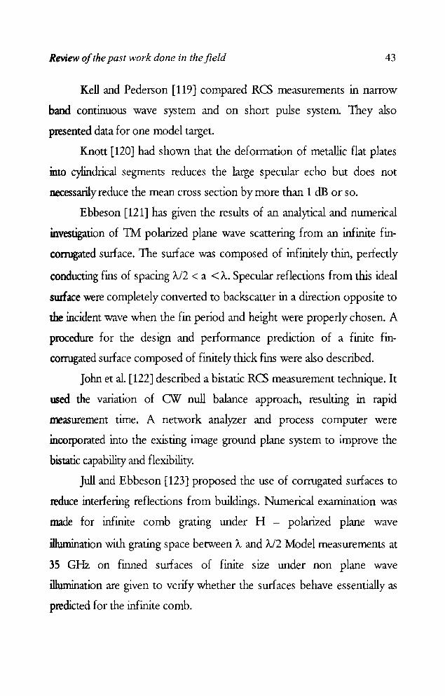
Kell and Pederson [119] compared RCS measurements in narrow
band continuous wave system and on short pulse system. They also
presented data for one model target.
Knott [120] had shown that the deformation of metallic flat plates
into cylindrical segments reduces the large specular echo but does not
necessarily reduce the mean cross section by more than 1 dB or so.
Ebbeson [121] has given the results of an analytical and numerical
investigation of TM polarized plane wave scattering from an infinite fin
conugated surface. The surface was composed of infinitely thin, perfectly
conducting fins of spacing A/2 < a <A. Specular reflections from this ideal
swface were completely converted to backscatter in a direction opposite to
the incident wave when the fin period and height were properly chosen. A
procedure for the design and performance prediction of a finite fin
corrugated surface composed of finitely thick fins were also described.
John et al. [122] described a bistatic RCS measurement technique. It
used the variation of CW null balance approach, resulting in rapid
measurement time. A network analyzer and process computer were
incorporated into the existing image grmll1d plane system to improve the
bistatic capability and flexibility.
Jull and Ebbeson [123] proposed the use of corrugated surfaces to
reduce interfering reflections from buildings. Numerical examination was
made for infinite comb grating under H - polarized plane wave
illumination with grating space between 'A and 'A/2 Model measurements at
35 GHz on finned surfaces of finite size under non plane wave
illumination are given to verify whether the sudaces behave essentially as
predicted for the infinite comb.
44 Chapter 2
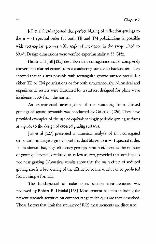
Jull et al [124] reported that perfect blazing of reflection gratings to
the n = -1 spectral order for both TE and TM polarizations is possible
with rectangular grooves with angle of incidence in the range 19.5 0 to
59.4°. Design dimensions were verified experimentally at 35 GHz.
Heath and Jull [125] described that corrugations could completely
convert specular reflection from a conducting surface to backscatter. They
showed that this was possible with rectangular groove surface profile for
either TE or TM polarizations or for both simultaneously. Numerical and
experimental results were illustrated for a surface, designed for plane wave
incidence at 500 from the nonnal.
An experimental investigation of the scattering from crossed
gratings of square pyramids was conducted by Cai et al. [126]. They have
provided examples of the use of equivalent singly periodic grating surfaces
as a guide to the design of crossed grating surfaces.
Jull et al [127] presented a numerical analysis of thin corrugated
strips with rectangular groove profiles, dual blazed to n = -1 spectral order.
It has shown that, high efficiency gratings remain efficient as the number
of grating elements is reduced to as few as two, provided that incidence is
not near grazing. Numerical results show that the main effect of reduced
grating size is a broadening of the diffracted beam, which can be predicted
from a simple formula.
The fundamental of radar cross section measurements was
reviewed by Robert B. Dybdal [128]. Measurement facilities including the
present research activities on compact range techniques are then described.
Those factors that limit the accuracy of RCS measurements are discussed.
Review of the past work done in the field 45
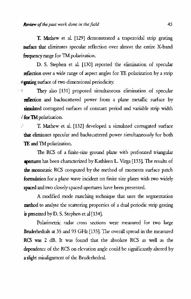
T. Mathew et al. [129] demonstrated a trapezoidal strip gratmg
sunace that eliminates specular reflection over ahnost the entire X-band
frequency range for 1M polarization.
D. S. Stephen et al. [130] reported the elimination of specular
reflection over a wide range of aspect angles for TE polarization by a strip
. 11 grating swface of two dimensional periodicity.
They also [131] proposed simultaneous elimination of specular
. reflection and backscattered power from a plane metallic swface by
simulated conugated surfaces of constant period and variable strip width
l.for 1M polarization.
T. Mathew et al. [132] developed a simulated corrugated surface
that eliminates specular and backscattered power simultaneously for both
TE and 1M polarization.
The RC) of a finite-size ground plane with perforated triangular
apertures has been characterized by Kathleen L. Virga [133]. The results of
the monostatic RC) computed by the method of moments swface patch
fOlDlulation for a plane wave incident on finite size plates with two widely
spaced and two closely spaced apertures have been presented.
A modified mode matching technique that uses the segmentation
method to analyse the scattering properties of a dual periodic strip grating
is presented by D. S. Stephen et al [134].
Polarimetric radar cross sections were measured for two large
Bruderhedrals at 35 and 93 GHz [135]. The overall spread in the measured
RCS was 2 dB. It was found that the absolute RC) as well as the
dependence of the RC) on elevation angle could be significantly altered by
a slight misalignment of the Bruderhedral.
46 Chapter 2
The transI11JSSIOn line modeling (1L11) method is applied to
detennine the radar cross section of very thin conducting targets under
critical illumination that are included in a benchmark of thin plates
proposed by the electromagnetic code consortium (EMCq for validation
of low-frequency electromagnetic computational codes [136].
S.Y. Wang and S. K. Jeng [137] proposed a compact closed-form
formula for the RC; of a perfectly conducting right dihedral corner
reflector at arbitrary aspect angles. M O. White [138] presented an
overview of radar cross section, measurements, prediction and control.
H Mosallaei and Y. Rahmat-Samii [139] presented a modal! GA
technique for RC; reduction in a wide-band frequency range for planar,
cylindrical, and spherical conducting structures. Using the GA method,
RC; of these structures is reduced more than 27 dB by designing an
optimized RAM coating. In addition, it is shown that the optimum RAM
coating designed for a planar structure can also reduce the RC; of the
cylindrical and spherical structures effectively.
A comparative study on target identification using RC; signature of
an aircraft in both the frequency domain and the range domain is proposed
byChan [140].
Smith [141] demonstrated a technique for measuring the RC; of
2D diffracting sources. The measured and predicted diffraction RC; of a
conducting halfplane edge and a gap in an otherwise infinite conducting
plane are presented. The technique may be used to measure the diffraction
coefficient of an impedance discontinuity.
P. Corona et al [142] analyzed the electromagnetic backscanering by
a perfectly conducting dihedral corner reflector with sinusoidal profiles
characterized by different periodicity values.
tAnUw of the past work done in the field 47
An application of the theory of open electromagnetic problems by
cin:uita1 analysis is presented by Penaranda [143] for the reduction of radar
,1,C!OSs sectiom of homogeneous cylinders V1ithout need for other dielectric
Lmedia
~~ V. Losada et al [144] proposed Galerkin's method in the Hankel
xttansfonn domain (HID) to the detennination of the Res of unloaded
nstacked circular microstrip patch antennas fabricated on a two-layered
'substrate which may be made of a uniaxial anisotropic dielectric, a
magnetized ferrite or a chiral material.
Richard Norland [145] showed how the assumption that specular
bac.kscattered reflection pattern of the flat plate reduces the induced
multipath error is constrained by the radar wavelength, geometric
parameters and by the plate dimension.
Misran et al [146] compared the perfonnance of a concentric ring
reflectarray element backed either by a solid metal ground plane or a
frequency-selective surface. Simulated and measured results showed that
the 'in-band' reflection phase response of the two structures is similar;
however, the periodic surface reduces the 'out-of-band' reflectivity of the
antenna by'more than 4 dB, thereby decreasing its Res profile to these
signals.
A E. Serebryannikov and A I. Nosich [147] developed a
generalized model to study the lE-polarized plane wave scattering by
coated and uncoated slotted circular cylinders of nonzero thickness and by
a filled and empty circular cylinders with sectoral cuttings.
Peixoto et al [148] investigated the Res reduction of dihedrals by
shaping and by application of Radar Absorbing Material (RA1v1).
48 Chapter 2
2.2 FRACT AL ELECTRODYNAMICS
The blend of fractal geometries and electromagnetics is called
fractal electrodynamics. A good reference on the basics of fractal
geometry, especially on how they penain to the field of electrodynamics is
described by D. L. Jaggard in [149]. Fractal geometry was first defined by
Benoit Mandelbrot [150], to define many perplexing geometries found in
nature. A very good reference for fractal antennas as elements and array
can be found in [151] by D. H Wemer and R Mittra.
J. Romeu and Y. Rahmat-Samii [152] proposed that the multiband
propenies of self-similar fractals can be advantageously exploited to design
multiband frequency selective surfaces. It is shown that the self similarity
of the Sierpinski dipole translates into a dual-band behaviour of a FSS
made by arraying a two iteration Sierpinski dipole.
C Puente-Baliarda et al [153] studied the multiband behaviour of
the fractal Sierpinski antenna.
D. H Wemer et al. [154] discussed about the recent developments
in the field of fractal anterma engineering, with particular emphasis placed
on the theory and design of fractal arrays.
C T. P. Song et al. [155] introduced a parallel feed staked fractal
antenna using square Sierpinski and diamond Sierpinski carpet, which are
suitable for applications in picocell environments for the operating bands
of GSM, DECf and W'LAN systems.
G. J. Walker and J. R James [156] proposed the concept of fractal
volume antenna in order to increase the degree of design freedom
associated with fractal antenna elements and hence improve their input
matching characteristics.

Review of the past work done in the field 49
z. Du et al [157] anal~ed the square microstrip fractal patch
antenna in a Sierpinski carpet and the effects of its elements. They
proposed that the multi-band frequency operation of the antenna res ulted
from the driven element and not from the parasitic fractal elements.
D. H Werner and D. Lee [158] proposed a technique for the design
of multiband and dual polarized frequency selective surfaces that is based
on the use of fractal screen elements.
D. H Werner and P. L. Werner [159] explained the fundamental
relationship between self-similar, that is, fractal, arra~ and their ability to
generate radiation patterns which posses fractal features. The theoretical
foundation and design procedures are developed for using fractal arra~ to
synthesize fractal radiation patterns having certain desired characteristic. A
family of functions, known as generalized Wierstrass functions, are shown
to play a pivotal role in the theory of fractal radiation pattern synthesis.
D. L. Jaggard and A D. Jaggard [160] examined the radiation
pattern from a new fractal array, the cantor ring array. They also studied
the case of thinned uniformly excited elements, and found that for large
fractal dimension and low lacunarity, the Cantor ring array is considerably
better than the periodic array, and appears to have lower sidelobes or a
large visible range for a given sidelobe level than similar random arra~ for
number of elements less than or equal to hundred.
Y. Kim and D. L. Jaggard [161] presented a novel method of
random array synthesis. It has been demonstrated that quasi-random arra~
posses the ability to control the sidelobe of the radiation pattern.
Using Sierpinski gasket as an example A Lakhtakia [162] showed
that the paraxial Fraunhoffer-zone diffracted field of a self-similar fractal
screen exhibits self-similarity.
50 Chapter 2
C. Peunte-Baliarda [163] described a novel approach to the design
of frequency independent systems based on fractal structures. The effort
has been focused in describing a technique to design low side-lobe and
multiband arrays, which has always been difficult due to the sensitivity of
most current design techniques to variations on the operating wavelength.
X. Sun and D. L. Jaggard [164] investigated the reflection and
transmission properties of finely divided fractallayers. They observed the
behaviour of electromagnetic or optical waves normally incident upon
generalized Cantor bar fractal multilayers for various fractal dimensions
and stages of growth.
D. H Wemer et al. [165] proposed a technique for generating sum
and difference pattern using Siepinski carpet based fractal subarrays.
M Lehman and M Garavaglia [166] obtained the input impedance
and the reflectance for a multilayer structure with periodic and fractal
distribution and demonstrated how it shows a self similar behaviour
according to the type of the structure.
D. L. Jaggard and Y. Kim [167] introduced the concept of band
limited fractals and used to describe the diffraction of electromagnetic and
optical waves by irregular structures. They demonstrated it through the
example of plane-wave diffraction by a fracta! phase screen of finite extent.
D. L. Jaggard and X. Sun [168] considered the scattering of
electromagnetic waves from perfectly conducting fractal surfaces. The
surface was modeled by a multiscaled bandlimited continuous fractal
function. They analytically developed a generalized Rayleigh solution for
electromagnetic wave scattenng from such fractal surfaces. After
examining the convergence of Rayleigh systems, they numerically

'- Review of the past work done in the field 51
, calculated the coupling strengths and related the angular scattering energy
~tribution to the fractal descriptors of the surface.
E. Jakeman [169] investigated on the scattenng by a
cOIrugated random surface with fractal slope. Wu and Hu [170] studied the
phase transitions on more complex Sierpinski carpets. Variations of the
critical exponents with various geometric factors and the scaling of resistor
networks are examined.
Reflection and transllllSslon propemes of polyadic fractal
superlattices are formulated, solved analytically, and characterized for
variations in fractal dimension, lacunarity, number of gaps, stage of
growth, and angle of incidence by AD. Jaggard and D. L. Jaggard [171].
D. L. Jaggard and X. Sun [172] investigated and characterized the
reflection and transmission properties of finely divided fractallayers.
The swface impedance of two thin metallic films of different fractal
structures realized on printed circuits have been measured in free-space
over the frequency range 10 GHz to 20 GHz by E. Troncet et al [173]. A
mode ling scheme based on Maxwell's equations and Fresnel's diffraction
theory is proposed.
C Puente Baliarda et al. [174] presented a model that explains the
behaviour of the Sietpinski fractal anterma. The model is applied to predict
the behaviour of the Sierpinski fractal antenna when the flare angle is
modified and its validity is assessed by comparing its predictions with
measured data.
D. H Wemer and S. Ganguly [175] has presented a comprehensive
overview of recent developments in the rapid growing field of fractal
antenna engmeenng.
52 Chapter 2
J. P. Gianvinorio et al [176] designed frequency selective surfaces
using the iterative techniques of fractals which exhibit two or three stop
bands depending on the number of iterations.
F. Chiadini et al [177] highlighted the self-similarity features of the
frequency dependent reflection coefficient of a dielectric cantor prefractal
obtained by applying cantor set construction to the optical layer lengths.
L Zhou et al [178] studied the reflective properties of a small
dielectric plate covered with fractal like metallic pattern generated by a
particular type of space filling CUIVes. They observed both experimentally
and theoretically that the plate could reflect electromagnetic waves in a
multitude of frequencies, generated from a near field mono pole antenna.
e. T. P. Song et al [179] demonstrated a novel method for
designing a wide band quasi-log periodic monopole antenna based on the
principles of the fractal Sierpinski gasket and circular disk monopole.
D. H Werner et al [180] presented a novel method for designing
reconfigurable multi-band linear and planar antenna arrays.
D. H Werner et al [181] proposed a methodology for exploiting the
self-similarity and symmetry in the geometrical structure of fractal arrays to
develop fast algorithms for calculating the impedance matrix and driving
point impedance.
From the above review of past work in the field, it is clear that
many researchers have studied the scattering properties of strip gratings
and to reduce Res of targets using strip grating tedll1ique. No work has
been reponed for reducing Res of a target using fractal based metalo
dielectric structure. This thesis is the outcome of the investigations carried
out to reduce the Res of targets by applying Metallo-Dielectric Structures

Review of the past work done in the field 53
(MDS) based on fractal geometries on the target surfaces. The scattering
characteristics of simple targets like flat plate, dihedral corner and cylinder
loaded with 1105 are investigated.

~' 1$. J Chapter 3
METHODOLOGY
'11Iis chapter highlights the methodology adopted for the work presented
in this thesis. Description of the different types of targets investigated
and their fabrication details are presented. The measurement techniques
as well as the essential facilities used for the study are also described.
fMethodology 57
·3.1 OVERVIEW OF RCS MEASUREMENT SYSTEMS
During the past several years, the increasing interest in the radar
signature reduction techniques has induced the development of Radar
Goss Section (RCS) measurement facilities. The demand for accurate
measurements of radar reflectivity of targets has resulted in proliferation of
RCS measurement systems. Technological advances in coherent wavefonn
generation, along with high speed digital signal processing, have opened
door for utilizing the radar for target identification and classification. In
R~ measurements, the response of the target is analyzed by bO\.Ulcing
radar signals off the targets and picking up the returned signals with the
recelvmg antenna.
An RCS measurement system has the following basic elements.
~ An Instrumentation radar capable of launching and recelvrng a
microwave signal of sufficient intensity
~ Data processing and recording equipments
~ A low reflection environment
~ Target support fixture and turn table
Nowadays, there are nwnerous commercial and in- house radars
that cover wide frequency range and bands centered at different
frequencies in the microwave region. The various radar systems include
continuous wave (CW), frequency modulated CW (FMCW) , interrupted
FMCW, pulsed, etc. Almost all systems in use today are coherent, that is,
they are capable of measuring both amplitude and phase.

58 Chapter 3
A low reflection environment is an outdoor test range or an
indoor chamber whose walls are covered with absorbing materials to
reduce reflection. The target is supported on a specially designed support
fixture with low reflectivity. The target support is fixed on a turn table. For
accurate measurements, the target must be at sufficiently long distance
from the radar so that the incident electromagnetic wave is plane over the
target.
To allow the selection of an appropnate RCS measurement
system, the system performance required for a given application must be
specified. Key performance criteria include frequency coverage, range of
targets and measurement accuracy. Depending on the application, Res
may be measured as a function of target position, frequency, transmit
receive polarization or bistauc angle between the transmitter and receiver.
The potential errors in RCS measurements can be reduced by means of
careful instrumentation and facility design.
A linear relationship between the final processed amplitude or
phase of a detected signal relative to the amplitude and phase of the input
signal must be maintained over the operating dynamic range, when
accurate measurements are to be made. The absolute accuracy of the Res
measurements is dependent on the validity of primary system calibration
and system stability. The primary system calibration is generally
accomplished by replacing the target with a reflector of known Res.
In the present work, measurements are carried out using HP
8510C/ Rohde & Schwarz ZVB 20 vector network analyzer. The targets
are fixed on a turn table kept inside an anechoic chamber.
Methodology 59
3.2 MAJOR FACILITIES USED IN RCS MEASURErvlENTS
3.2.1 ANEo-IOIC GIAMBER
In indoor antenna pattern and Res measurements, the
reflections from the surrounding walls, objects and external radiation may
create errors. Proper care has to be taken to avoid such spurious
reflections for better accuracy. Hence Res measurements are conducted in
a facility called "Anechoic chamber" for avoiding spurious reflections.
An anechoic chamber is an artificially simulated free space
environment in which the electromagnetic wave propagation studies can
be performed with good accuracy. TIlls is a large room whose interior
portions are covered with microwave absorbers, having good coefficient of
absotption in the frequency range of interest. Instead of flat sheet
absorbers, pyramidal and wedge shaped absorbers are used to reduce the
reflections further. In the present chamber, conunercially available
polyurethane foam based microwave absorbing material is used for
covering the inner walls and floor of the chamber. Electromagnetic
interference shielding is provided by putting thin aluminium sheets
between the absorbers and the walls of the room.
Monostatic Res measurements of different targets were carried
out in a tapered anechoic chamber. For bistatic measurements and to study
the scattered power distribution, a new facility in an anechoic environment
is designed and built up.

60 Chapter 3
3.2.2 NE TWORK ANALYSER
A network analyzer is an equipment incorporating swept-frequency
measurements to characterize the complex network parameters of a device
with high speed and accuracy. Network analysis is accomplished by
creating data model of transfer and impedance characteristics of a linear
network through stimulus response testing over the frequency band of
interest. A vector network analyser measures both the magnitude and
phase of the reflection and transmission coefficients.
1he roam components of a vector network analyzer are, a
ll1lcrowave source, an S-parameter or reflection/transmission test set,
frequency convener, detector and a display unit. The sweep oscillator
generates RF signal to stimulate the device under test. The transducer,
which is the reflection/ transmission test unit, is connected between the
signal source and the receiver. It has a three fold function. The first is to
split the incoming signal into reference and test signals. Secondly it is
capable of extending the electrical length of reference channel, so that the
distances traveled by the reference and test signals are equal. Finally it
connects the system properly for transmission or reflection measurements.
In the receiver, the harmonic convener mixes the RF signal with a local
oscillator output and the resultant IF is given to the display unit.
An HP 8510C vector network analyzer is used for the monostatic
RCS measurements of different targets described in this work This is a
fully computer controlled system capable of measuring transmission and
reflection characteristics of passive and active networks in the fonn of
Methodology 61
gain, S-parameters and nonnalized impedance in the range of 45 :tv1Hz to
20 GHz. TIlls system uses HP 8341B sweep oscillator and HP 8514 S -
parameter test set. Measurements can be done either in ramp or stepped
sweep mode. The ramp sweep mode is fast enough to make real-time
measurements. The stepped sweep mode is more accurate but slower as it
synthesizes each measured frequency.
The measurement results can be displayed on one of the
independent channels of the network analyzer. The channels can be
displayed simultaneously with results presented in logaritlunic/linear
magnitude, phase or group delay format or polar coordinates. With time
domain gating technique, undesired responses can be removed, thereby
increasing the accuracy of measurement. The measured data is acquired
and stored in a PC interfaced with the network analyser.
3.2.3 T ARGE T POSITIONER AND CONTROLLER
For measuring RCS pattern, the target is rotated about a vertical
axis in the azimuth plane keeping the transmitter antenna stationary. A
target positioner (turn table) which can be controlled using a PC is used for
the pattern measurement. A stepper motor based turn table is used so as to
rotate the target to the required angle and take the measurements.
3.3 MEASUREMENT TECHNIQUES
Monostatic measurements are done in a tapered anechoic chamber.
The target is mounted on a target support which is a thin, cylindrical

62 Chapter 3
colwnn made of wood which is attached to the turn table, kept at the quite
zone of the chamber. The target alignment combines the use of laser beam
reflections from the target and visual sighting techniques, depending on
the target geometry. A set of wide band horn antennas is used to illuminate
the target and measure the backscanered power. The two horn antennas
are arranged with a small bistatic angle of 3°. The error incurred in RCS
measurements by this bistatic angle is negligible. Microwave absorbing
materials are interposed between two antennas to avoid leakage from
transminer to receiver. Schematic of the measurement setup is shown in
figure 1.
Network Analyser
* ••
Sweep Osc.
Test Set
Anechoic Chamber
t Tx
Rx.
Figure 1 Measurement setup
~t+ Target mount
Turntable
The RCS measurement s)'tem uses a calibration technique which
allows the internal error correction capabilities of HP 8510 C to calibrate
the anechoic chamber without target. The transmission coefficient (S,,) of
the anechoic chamber without target is first measured. Then the reference

Methodology 63
target is placed and a THRU RESPOSE calibration is performed in the
Network Analyser and stored in the CAL SET. The result of empty
chamber and reference target measurements are used to generate
calibration coefficients used in error correction of the system so that the
background return is directly removed from the measurements.
For getting the RCS patterns, the positioner moves the target to the
start angle of measurement. Network analyzer is triggered to take
measurements and computer acquires the data for this position. After that,
a control pulse is sent to the positioner to move through the next step
angle and another pulse will be sent back to the computer for reading this
data. Thus the data is acquired for each step angle of measurement. The
measured data is stored in the computer which can be used for obtaining
the RCS pattern at the desired frequency.
3.3.1 ARCH METHOD
The Arch method is used to study the distribution of scattered
power around the target. The setup is indigenously fabricated in an
anechoic environment. The Arch is a semicircular wooden frame that
allows the transmitting and receiving antennas to be fixed at a constant
distance from the centre of the test panel, for a variety of subtended
angles. The transmitting antenna mounted on a wooden carriage is placed
closed to the arch. The metallo-diclectric structure with proper metallic
backing plate is placed on a turntable at the centre of the arch. The
receiving antenna is moved on the arch for measuring the scattered power
from the target of interest for an angle of 180°. For this, a stepper motor
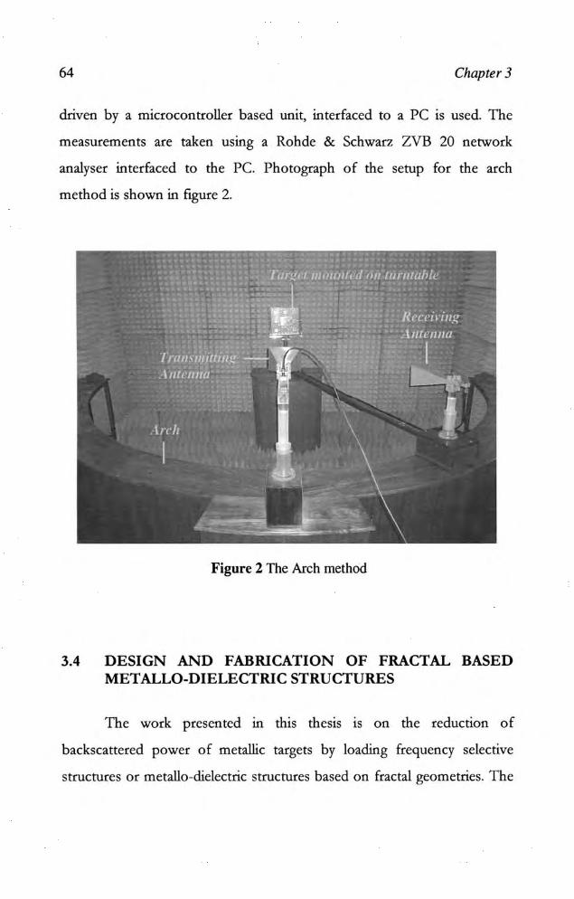
64 Chapter 3
driven by a microcontroller based unit. interfaced to a PC is used. The
measurements are taken using a Rohde & Schwarz ZVB 20 network
analyser interfaced to the Pc. Photograph of the setup for the arch
method is shown in figure 2.
Figure 2 The Arch method
3.4 DESIGN AND FABRICATION OF FRACTAL BASED METALLO-DlELECTRIC STRUCTURES
The work presented in this thesis is on the reduction of
backscauered power of metallic targets by loading frequency selective
structures or metallo~dielectric structures based on fractal geometries. T he
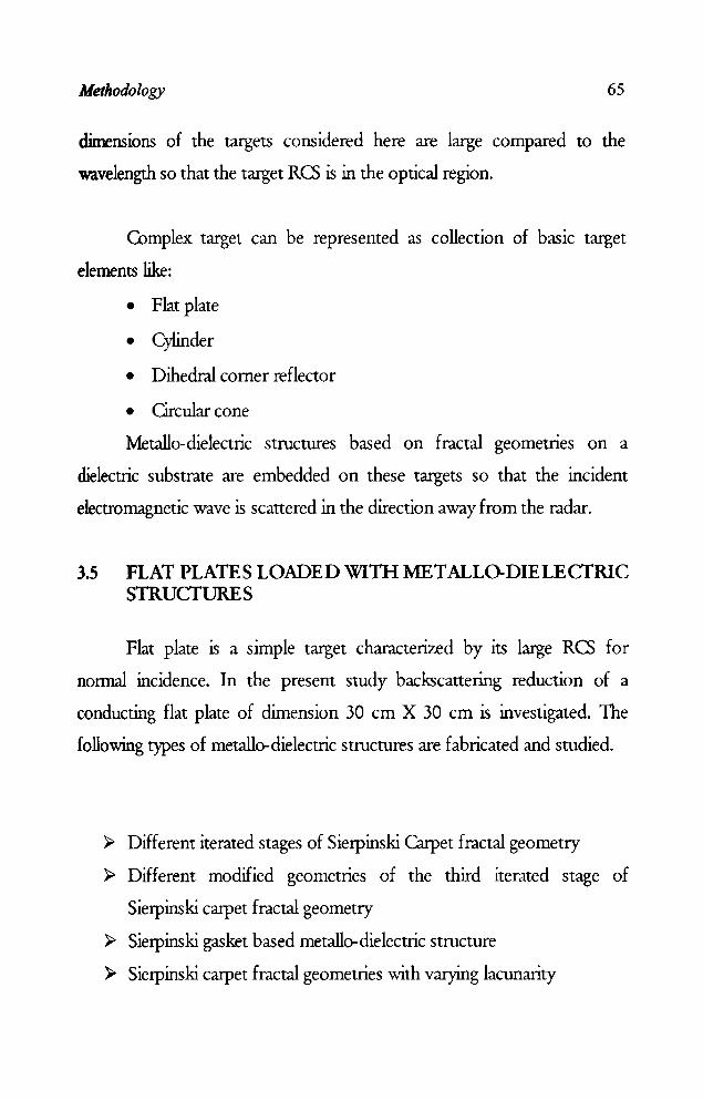
Methodology 65
dimensions of the targets considered here are large compared to the
wavelength so that the target RC) is in the optical region.
Complex target can be represented as collection of basic target
elements like:
• Flat plate
• Cylinder
• Dihedral corner reflector
• Circular cone
Metallo-dielectric structures based on fractal geometnes on a
dielectric substrate are embedded on these targets so that the incident
electromagnetic wave is scattered in the direction away from the radar.
3.5 FLAT PLATES LOADED WITH MET ALLO-DIELECfRIC STRUCfURES
Flat plate is a simple target characterized by its large RC) for
normal incidence. In the present study backscattering reduction of a
conducting flat plate of dimension 30 cm X 30 cm is investigated. The
following types of metallo-dielectric structures are fabricated and studied.
);> Different iterated stages of Sierpinski Carpet fractal geometry
);> Different modified geometries of the third iterated stage of
Sierpinski carpet fractal geometry
);> Sierpinski gasket based metallo-dielectric structure
);> Sierpinski carpet fractal geometries with varying lacunarity
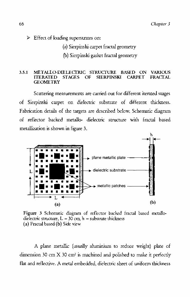
66
~ Effect of loading superstrates on:
(a) Sierpinski carpet fractal geometry
(b) Sierpinski gasket fractal geometry
Chapter 3
3.5.1 METALL()'DIELECTRIC STRUCTURE BASED ON VARIOUS ITERATED STAGES OF SIERPINSKI CARPET FRACTAL GEOMETRY
Scattering measurements are carried out for different iterated stages
of Sierpinski carpet on dielectric substrate of different thickness.
Fabrication details of the targets are described below. Schematic diagram
of reflector backed metallo- dielectric structure with fractal based
metallization is shown in figure 3. h
• • • • ••••• ••••••••• plane metallic plate ---~-• • • • • • • • •
L ••• I(.i!;t--. dielectric substrate -----~ •
• • • • • •
-*,+--7--. metallic patches ---... ",
• • • • • • L
(a) (b)
Figure 3 Schematic diagram of reflector backed fractal based metallodielectric structure, L = 30 cm, h = substrate thickness (a) Fractal based (b) Side view
A plane metallic (usually aluminium to reduce weight) plate of
dimension 30 cm X 30 cm2 is machined and polished to make it perfectly
flat and reflective. A metal embedded, dielectric sheet of uniform thickness
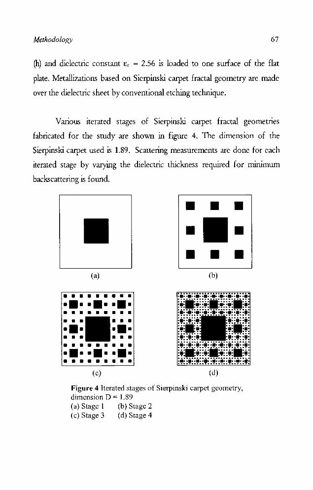
Methodology 67
(h) and dielectric constant Er = 2.56 is loaded to one surface of the flat
plate. Metallizations based on Sierpinski carpet fractal geometry are made
over the dielectric sheet by conventional etching technique.
Various iterated stages of Sierpinski carpet fractal geometnes
fabricated for the study are shown in figure 4. The dimension of the
Sierpinski carpet used is 1.89. Scattering measurements are done for each
iterated stage by varying the dielectric thickness required for minimum
backscattering is found.
• • • • • • • •
(a) (b)
• • • • • • • • • ••••••••• • • • • • • • • • • • • • • • ••• ••• • • • • • • • • • • • • • • • ••••••••• • • • • • • • • •
(c) (d)
Figure 4 Iterated stages of Sierpinski carpet geometry, dimension D = 1.89 (a) Stage 1 (b) Stage 2 (c) Stage 3 (d) Stage 4

68 Chapter 3
3.5.2 STRUCTURES BASED ON THE THIRD ITERATED STAGE OF SIERPINSKI CARPET FRACTAL GEOMETRY WITH GENERATORS OF DIFFERENT SHAPES
To study the effect of the shape of individual elements on
backscattering, Sierpinski carpet fractal geometries with patches of
different shapes are fabricated as shown in figure 5.
• • • • • • • • • ••••••••• • • • • • • • • • • • • • • • ••• ••• • • • • • • • • • • • • • • • ••••••••• • • • • • • • • •
Cross
• • • • • • • • • ••• ••• ••• • • • • • • • • • • • • ••• ••• ••• • • • • • • • • • • • • • • • ••••••••• • • • • • • • • •
Hexagon
• • • • • • • • • .+ .. + .. +. • • • • • • • • • • • • • •• . +. .+ . • • • • • • • • • • • • • • • .+ .. + .. +. • • • • • • • • •
Diamond
• • • • • • • • • • •••••••• • • • • • • • • • • • • ••• ••• • •• • • • ••• • • • • • • • • • • •••••••• • • • • • • • • •
Octagon
• • • • • • • • • ••••••••• • • • • • • • • • • • • • • • ••• ••• • • • • • • • • • • • • • • • • •••••••• • • • • • • • • •
Circle
x x x x x x x x x xXx xXx xXx x x x x x x x x x
xxxxxxx xXx xXx x x x x x x xxxxxxxxx xXx xXx xXx xxxxxxxxx
Purina square
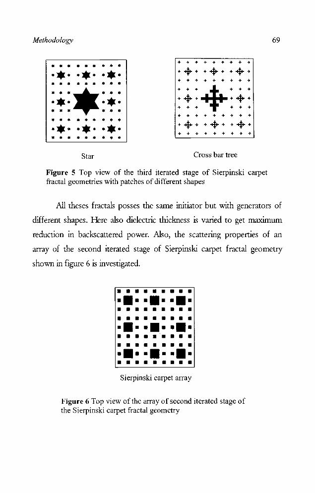
Methodology
+ + + + + + + + + • • • • • • • • • . *. . * . .* . + -+ + + + + ++ + + + + + + + + + + • • • • • • • • • ... +". • • • • • • . *. .* . +++ +++ + + + + + + • • • • • • + + + + + + + + + • • • • • • • • • +++ + -+ + + -+ + . *. . * . .* . + + + + + + + + + • • • • • • • • •
Star Cross bar tree
Figure 5 Top view of the third iterated stage of Sierpinski carpet fractal geometries with patches of different shapes
69
All theses fractals posses the same initiator but with generators of
different shapes. Here also dielectric thickness is varied to get maximum
reduction in backscanered power. Also, the scanering properties of an
array of the second iterated stage of Sietpinski catpet fractal geometry
shown in figure 6 is investigated.
• • • • • • • • • ••••••••• • • • • • • • • • • • • • • • • • • ••••••••• • • • • • • • • • • • • • • • • • • ••••••••• • • • • • • • • • Sierpinski carpet array
Figure 6 Top view of the array of second iterated stage of the Sierpinski carpet fractal geometry
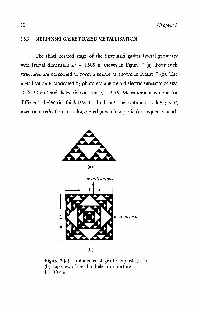
70 Chapter 3
3.5.3 SIERPINSKI GASKET BASED METALLISATION
The third iterated stage of the Sietpinski gasket fractal geometry
with fractal dimension D = 1.585 is shown in Figure 7 (a). Four such
structures are combined to form a square as shown in Figure 7 (b). The
metallization is fabricated by photo etching on a dielectric substrate of size
30 X 30 cm2 and dielectric constant er = 2.56. Measurement is done for
different dielectric thickness to find out the optimum value giving
maximum reduction in backscanered power in a particular frequency band.
(a)
metallisations
dielectric
(b)
Figure 7 (a) Third iterated stage of Sierpinski gasket (b) Top view ofmetallo-dielectric structure L= 30 cm
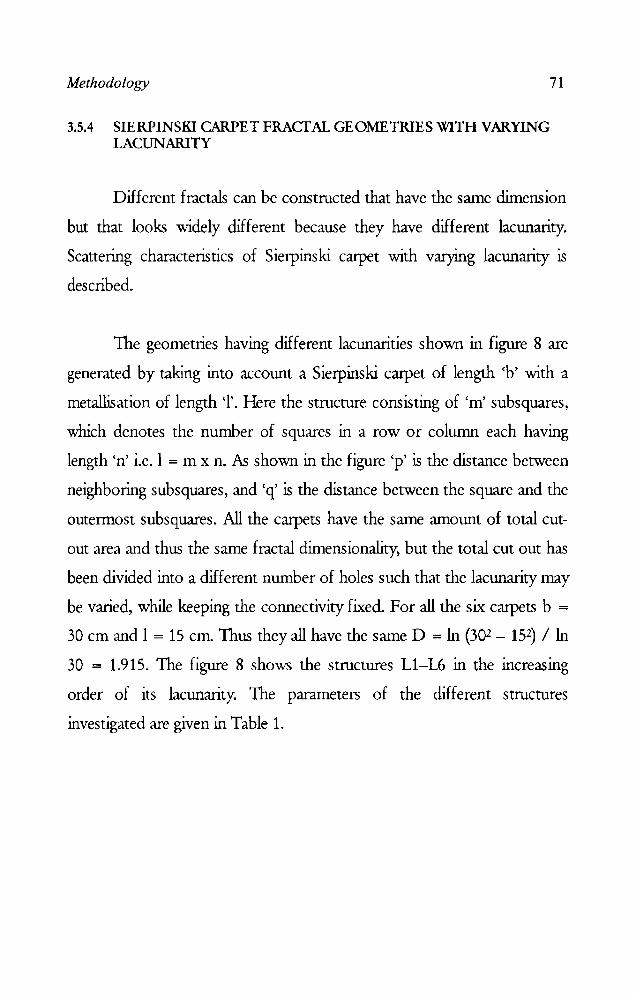
Methodology
3.5.4 SIERPINSKI CARPET FRACfAL GEOMETRIES WITH VARYING LACUNARITY
71
Different fractals can be constructed that have the same dimension
but that looks widely different because they have different lacunarity.
Scattering characteristics of Sierpinski carpet with varying lacunarity is
described.
The geometries having different lacunarities shown in figure 8 are
generated by taking into account a Sierpinski carpet of length cb' with a
metallisation of length '1'. Here the structure consisting of 'm' subsquares,
which denotes the number of squares in a row or column each having
length en' i.e. 1 = m x n. As shown in the figure 'p' is the distance between
neighboring subsquares, and 'q' is the distance between the square and the
outermost subsquares. All the carpets have the same amount of total cut
out area and thus the same fractal dimensionality, but the total cut out has
been divided into a different number of holes such that the lacunarity may
be varied, while keeping the connectivity fixed. For all the six carpets b =
30 cm and I = 15 cm. Thus they all have the same D = In (302 - 152) / In
30 = 1.915. The figure 8 shows the structures LI-L6 in the increasing
order of its lacunarity. The parameters of the different structures
investigated are given in Table 1.
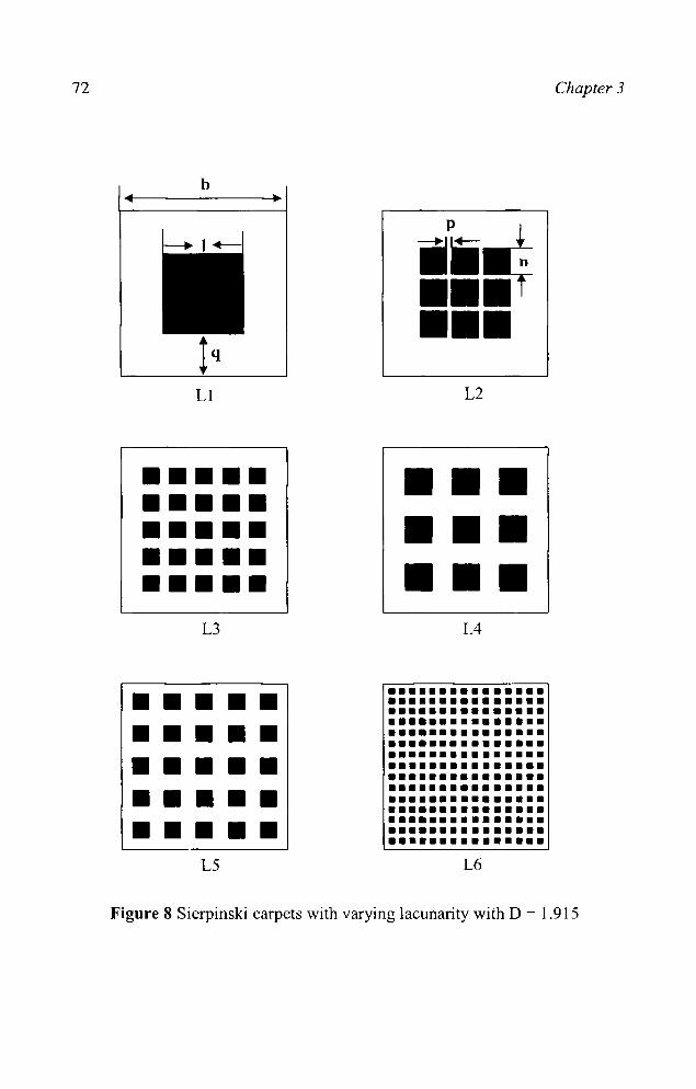
72
b
L1
••••• ••••• ••••• ••••• ••••• L3
• • • • • • • • • • • • • • • • • • • • • • • • • L5
ji~ •• if 111111
L2
111111 111111 111111
L4
••••••••••••••• ••••••••••• ••• ••••••••••• ••• ••••••••••• • ••••••••••• • ••••••••••• • ••••••••••• • ••••••••••• • ••••••••••• • ••••••••••• • ••••••••••• • ••••••••••• • ••••••••••• • ••••••••••• • ••••••••••• • L6
Chapter 3
Figure 8 Sierpinski carpets with varying lacunarity with D = 1.915
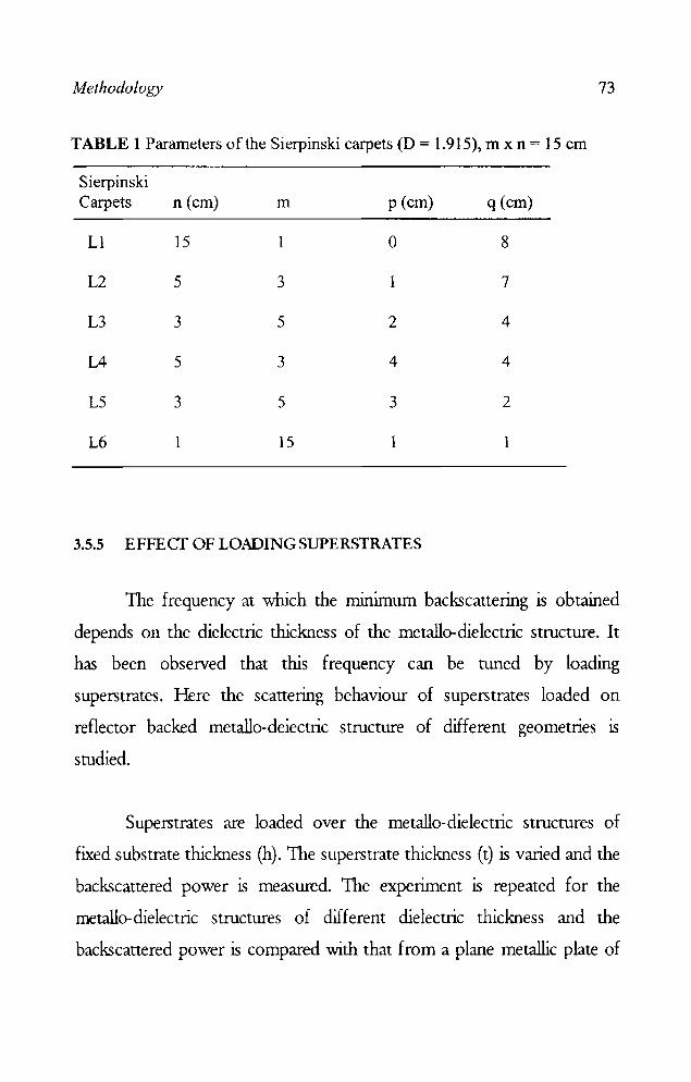
Methodology 73
TABLE 1 Parameters of the Sierpinski carpets (D = 1.915), m x n = 15 cm
Sierpinski Carpets n (cm) m p (cm) q (cm)
Ll 15 1 0 8
L2 5 3 1 7
L3 3 5 2 4
L4 5 3 4 4
L5 3 5 3 2
L6 15 1
3.5.5 EFFECf OF LOADING SUPERSTRATES
The frequency at which the minimrun backscattering is obtained
depends on the dielectric thickness of the metallo-dielectric structure. It
has been observed that this frequency can be tuned by loading
superstrates. Here the scattering behaviour of superstrates loaded on
reflector backed metallo-deiectric structure of different geometries is
studied.
Superstrates are loaded over the metallo-dielectric structures of
fixed substrate thickness (h). The superstrate thickness (t) is varied and the
backscattered power is measured. The experiment is repeated for the
metallo-dielectric structures of different dielectric thickness and the
backscattered power is compared with that from a plane metallic plate of
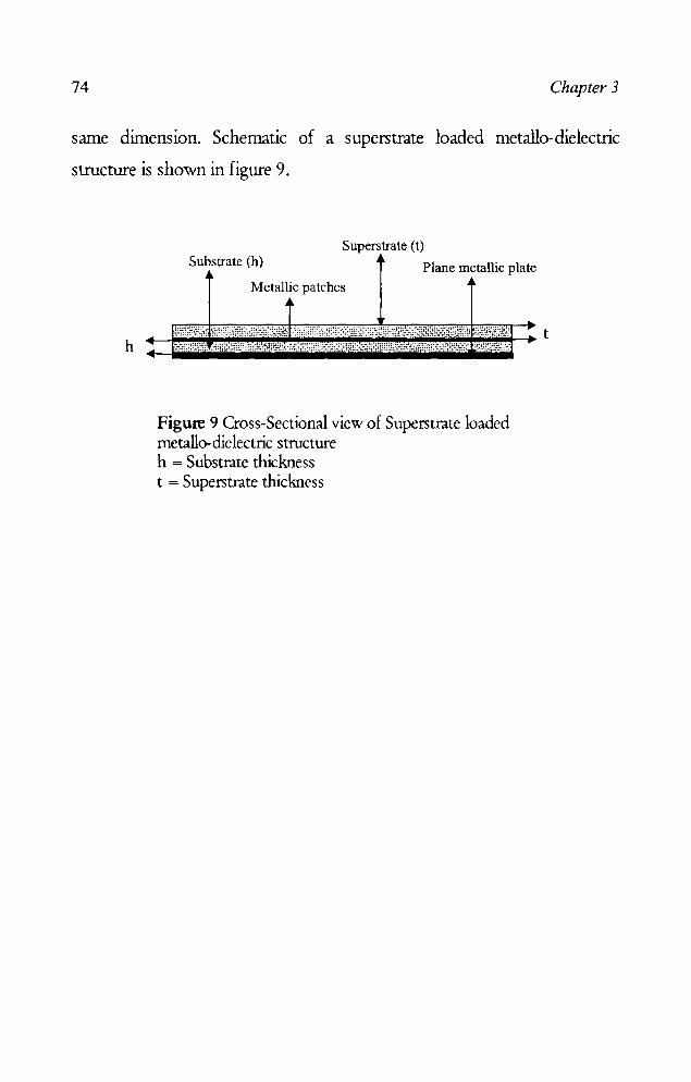
74 Chapter 3
same dimension. Schematic of a superstrate loaded metallo-dielectric
structure is shown in figure 9.
h
Superstrate (t) Substrate (h) Plane metallic plate
Metallic patches
Figure 9 Cross-Sectional view of Superstrate loaded metallo-die lectric structure h = Substrate thickness t = Superstrate thickness
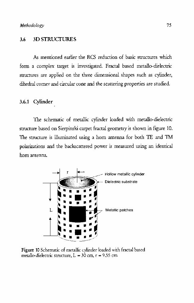
Methodology 75
3.6 3D STRUCTURES
As mentioned earlier the RCS reduction of basic structures which
fOIm a complex target is investigated. Fractal based metallo-dielectric
structures are applied on the three dimensional shapes such as cylinder,
dihedral corner and circular cone and the scattering properties are studied.
3.6.1 Cylinder
The schematic of metallic cylinder loaded with metallo-dielectric
structure based on Sierpinski carpet fraetal geometry is shown in figure 10.
The structure is illuminated using a horn antenna for both 'lE and 1M
polarizations and the backscattered power is measured using an identical
horn antenna.
L
••• • • ,~.,-----~-----"..,.. .... ' -
Hollow metallic cylinder
Dielectric substrate
Metallic patches
Figure 10 Schematic of metallic cylinder loaded with fractal based rnetallo-dielectric structure, L = 30 cm, r = 9.55 cm
76 Chapter 3
Measurements are perfonned by varying the dielectric thickness for both
IT and 1M polarizations and the optimum dielectric thickness giving
minimum hackscattered power is found out. The backscattered power at
various angles of incidence is measured by rotating the target. The
backscattered power from these structures is compared with that of an
unloaded plane metallic plate or cylinder of the same dimension.
3.6.2 Dihedral corner reflector
Right angled dihedral corner reflector provides a large radar cross
section over a wide angular range in a plane normal to its wedge. The large
echo which arises due to multiple reflections from the two mutually
orthogonal flat surfaces dominates the backscattered pattern. The flat
surfaces of the dihedral corner reflector are loaded with fractal structures
and the backscattering is measured. This is repeated for different corner
angles.
The dihedral corner reflector is formed by attaching two square
metallic plates of side L = 30 cm on a hinge arrangement. The structure is
specially designed so as to vary the corner angle precisely from 0 to 180°.
The metallization based on Sierpinski carpet fractal geometry is fabricated
on a dielectric substrate material of Er = 2.56 and is insened in the corner
reflector as shown in figure 11. The target under test is mounted on a
suppon which is attached to the turn table kept at the quiet wne of the
anechoic chamber. A set of wide band horn antennas are used to
ilhuninate the target and to measure the backscattered field. The
measurements are perfonned for 1E and 1M polarizations for different
Methodology 77
corner angles. Effect of dielectric thickness for each corner angle is
studied. A metallic dihedral corner reflector of the same dimension is used
as the reference target.
Metallizations Metal Plate
u
Figure 11 Dihedral corner reflector loaded with fractal based metallo-dielectric structure, L = 30 cm
3.6.3 Circular cone
r
1
M etallic patches
.. • • • • • •
L
Direction of propagation
..
Figure U Metallic circular cone loaded with array of Sierpinski carpet fractal geometry, radius = 11 cm, L = 22 cm.
78 Chapter 3
A metallic circular cone of outer radius r = 11 cm and length L =
22 cm is used in the present study. Fractal structure based on the array of
Sierpinski carpet is fabricated on a dielectric substrate and is loaded over
the metallic cone as shown in figure 12.
The direction of the incident wave is as indicated in the figure. The
backscattered power is measured for the structure for different dielectric
substrate thickness and is compared with a square metallic plate of same
base area of 22 cm2• The optimum thickness giving minimum
backscattering is found out. The variation of backscattered power for
different angles of incidence is measured by rotating the structure on the
turntable.

Chapter 4
EXPERIMENTAL RESULTS
This chapter highlights the results of the scattering measurements
carried out on different targets such as flat plate cylinder, dihedral
corner reflector and circular cone, loaded with metal/o-dielectric
structures based on jractal geometries. The scattering characteristics of
the above targets with different parameters are measured for TE and
TM polarizations in C, X and Kufrequency bands.
Experimental Results 81
Reduction of Radar G-oss Section (Ra;) of targets is of great
importance in the design of low detectable targets. The conventional
methods of Ra; reduction are shaping of targets, use of absorbing
materials, passive cancellation and active cancellation. It is also possible to
reduce the RCS of targets by modifying its scattering propenies so that the
scattered energy is diverted away from the radar. This can be achieved by
loading dielectric backed metallisations (metallo-dielectric structures) on
the target surface.
The results of the scattering measurements carned out on different
targets loaded with metallo-dielectric structures based on fractal geometries
are described in this chapter. The investigations were carried out in the
frequency range 4.5 GHz - 16 GHz. As mentioned in the previous
chapter, the following targets which form the basic building blocks of any
complex target are investigated.
~ Flat plate
~ Cylinder
~ Dihedral corner reflector
~ Circular cone
Fractal based metallo-dielectric structures (MDS) etched on
dielectric substrates of different thickness are loaded over these targets.
The parameters of the 11DS were optimized to produce large reduction in
backscattering. The results of the backscattering measurements for TE and
1M polarizations of the incident electromagnetic waves are presented and
compared with that of the original target.
82 Chapter 4
• TE - polarizations : Magnetic field perpendicular to the plane of
incidence
• TM - polarizations : Electric field petpendicular to the plane of
incidence
4.1 FLAT PLATES LOADED WITH FRACTAL BASED ME T ALLO DIELECTRIC STRUCTURES (MDS)
Measurement results of the flat plates loaded with fractal based
1v1DS is presented in this section. The following types of fractal structures
were investigated.
y Different iterated stages of Sierpinski carpet fractal geometry
y Sierpinski carpet fractal geometry with different patch shapes
Y Sierpinski gasket based metallo-dielectric structure
Y Fractal geometries with varying laclUlarity
The scattering characteristics of the above targets were measured
for TE and TM polarizations in C X and Ku bands to study the following.
• Variation of backscattered power with frequency
• Variation of backscattered power with angle of incidence.
• Angular distribution of the scattered power
• Olange in backscattered power with dielectric thickness, fractal
geometry, patch shape and dielectric constant
• Effect of loading superstrates

Experimental Results 83
4.1.1 Different Iterated Stages of Sietpinski Catpet Fractal Geometry
Here, the backscattering measurements were taken for both 1E and
'I'M: polarized fields incident nonnallyon the target. The first iterated stage
of Sierpinski carpet fractal geometry and the scattered power measured for
different dielectric thickness compared to that of flat plate of same
dimension is shown in figure 4.1. Measured results for the second, third
and fourth iterated stages are shown in figures 4.2-4.4.
(a)
h ~2mm -.-.- - h ~ 3mm ------ h~4mm
- _.- - h ~ 5mm - -- h~6mm
•••• ••••••• Flat plate
5 6 7 8 9 10 11 12 13 14 15 16
Frequency (GHz)
(b)
Figure 4.1 ( a) First iterated stage of Sierpinski carpet fractal geometry (b) Variation of backscattered power with frequency
for different dielectric thickness (h)

84 Chapter 4
The backscattered power is measured for normal incidence in the range
of frequencies covering C, X and Ku bands. The measurement is repeated for
different iterated stages of the Sierpinski carpet fractal geometry. The dielectric
thickness is also varied in each case, and the results are shown in figures 4.1-4.4 .
• • • • • • • •
(a)
.--.. (l) "0 o ..•.......•.•..••.••.•••... .....•• .s..a--_~ ........ !..L!. • .,.. ____ d~ .. 1
r'-~.:::-:- --_. '- - . ...-' ..... ---~~----. ~--L-Cl)
~ o -10 C. "0
~ :§ -20
~ IJ)
~ -30 co .0 Cl)
> -40 ~ Q)
0::::
......... '--. -.,---._ - ~'-.>.c. ~ . - -.... r--- _.,r'- ~ --- ____ - .......... ..: ...... -:-./f\_ /' .""'-"-... _ r --.. ____ --<: ......... _\/" -.-;,.1....".J._-
-, r/-~'-,.)
h ~2mm h~3mm
h~4mm
h =5mm h = 6mm Flat plate
5 6 7 8 9 10 11 12 13 14 15 16
Frequency (GHz)
(b)
Figure 4.2 (a) Second iterated stage of Sierpinski carpet (b) Variation of backscattered power with frequency for
different dielectric thickness (h)

Experimental Results
-co 0 ~ ....
Q)
== 0 -10 a. "0 Q) .... Q) ...... -20 -ra (.) III
.::tt. -30 (.) ra .0 Q) > -40 :;:; ro Q)
a:::
• • • • • • • • • ••••••••• • • • • • • • • • • • • • • • ••• • •• • • • • • • • • • • • • • • • ••••••••• • • • • • • • • •
(a)
~""""".'-'-."-' •• c:.' • ••••••••••••• ••••••••••••••••••••• ~--- ....... ~ ••••••• -.-:::~::" ~ -- .--"_"- .:-;-:;:;::r---~ \, \ -.//.... .... """-/'/?''' " "--~ / --;>-"'-/_-----
5
~ \ \ ,\ \ I'\.-, f- I /' \ I I / / \ Y \-,. .. ,/' / ./
6
~\I \\I/,!, I
\ I \ I / '" / , '/ I "I
1 \ \ I \ I 11 \ I \ ! I, I j' ~
J \! \ \ I ~ h~ 2mm
h~ 3 mm h = 4 mm h ~ 5 mm h = 6 mm Flat Plate
7 8 9 10 11 12 13 14 15 16
Frequency (GHz)
(b)
Figure 4.3 (a) Third iterated stage of Sierpinski carpet (b) Variation of backscanered power with frequency for
different dielectric thickness (h)
85

86
........ en
0 "0 '-'
"-ID 3': 0 -10 a.
"0 ID "-ID -20 --et! (.) If) ~ -30 (.) et!
.D (]) > -40 :;::; et! ID
et:: -50
(a)
,,"":::..-.: .............. .,.:: •. : .............. ~.~.~-~~-.. . ............... /" \ I ,,-- - ./ ,..// . ...- --.. ..... ,\.... ~.- ~ '",,--V:'\~ ~./
" '/I' \"/ /,J \ "'-. ~ .~ . -, \ T I x / '" I
'" \, '.j' )\', '''I \ I '- 7 ,,'. i'- , '-~ I ~ t \ I: ,\ \' I
\ . \ I I V \ J I \' \: I I "-., , I, \' I. t 1'1\ 'I \' I ' \ ,
~ 1/
h=2mm - - - - h =3mm ------ h=4mm
h=5mm --- h=6mm ••••••••••• Flat P'ate
Chapter 4
5 6 7 8 9 10 11 12 13 14 15 16
Frequency (GHz)
(b)
Figure 4.4 (a) Fourth iterated stage of Sierpinski carpet fractal geometry (b) Variation of backscattered power with frequency for
different dielectric thickness (h)
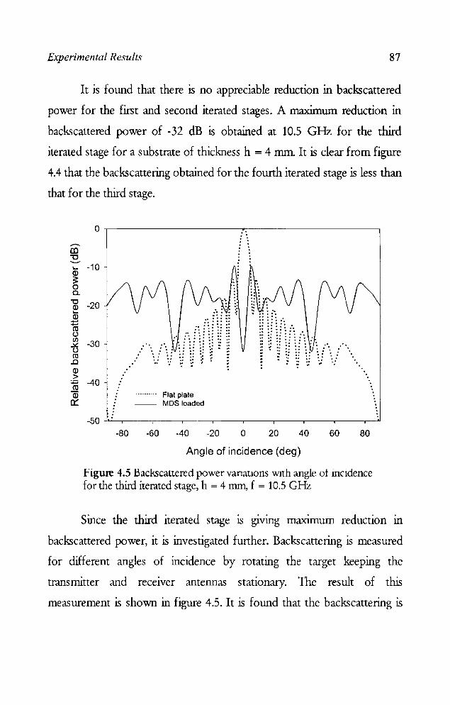
Experimental Results 87
It is found that there is no appreciable reduction in backscattered
power for the first and second iterated stages. A maximum reduction in
backscattered power of -32 dB is obtained at 10.5 GHz for the third
iterated stage for a substrate of thickness h = 4 mm. It is clear from figure
4.4 that the backscattering obtained for the fourth iterated stage is less than
that for the third stage.
o .--------------------.~,-------------------. ..-CD "tJ ......., .... -10
~ o a. "'C ~ -20 Q) ..... ..... co ()
~ -30 () co .c Q)
> :.:::; -40 co Q)
c:::
· . · . , . · ' · . , . , . · . · . , .
.. ' • a ••• -0-" • .I' ........ ._ ._0._
• .... 0 ••
. .... . '\j vW~~ 1
Flat plate -- MDS loaded
"
'. "
-50 ~,---_.--~~--~--_.--_,----._--_.--_.~
-80 -60 -40 -20 o 20 40 60 80
Angle of incidence (deg)
Figure 4.5 Backscattered power vanatlons WIth angle ot inCldence for the third iterated stage, h = 4 mm, f = 10,5 GHz
Since the third iterated stage is giving maximum reduction in
backscattered power, it is investigated further. Backscattering is measured
for different angles of incidence by rotating the target keeping the
transmitter and receiver antennas stationary. The result of this
measurement is shown in figure 4.5. It is found that the backscattering is
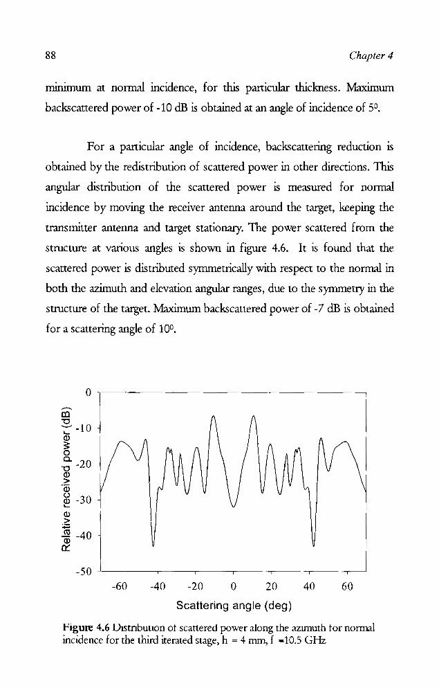
88 Chapter 4
mmunum at normal incidence, for this particular thickness. Maximum
backscanered power of -10 dB is obtained at an angle of incidence of 5°,
For a particular angle of incidence, backscanering reduction is
obtained by the redistribution of scanered power in other directions. This
angular distribution of the scanered power is measured for normal
incidence by moving the receiver antenna around the target, keeping the
traIlsminer antenna and target stationary. The power scanered from the
structure at various angles is shown in figure 4.6. It is found that the
scanered power is distributed symmetrically with respect to the normal in
both the azimuth and elevation angular ranges, due to the symmetry in the
structure of the target. Maximum backscattered power of -7 dB is obtained
for a scanering angle of 10°.
o .---------------------------------------~ -III "0 -::--10 ID ~ o a. -20 -0 ID >
'Q) o ID -30 L...
ID > :.;= m -40 ID
0:::
-60 -40 -20 o 20 40 60
Scattering angle (deg)
Figure 4.6 1)1stnbutton ot scattered power along the aZllTIuth tor normal incidence for the third iterated stage, h = 4 mm, f =10.5 GHz

Experimental Results 89
4.1.2 Sierpinski carpet with different patch shapes
From the previous section it is concluded that the third iterated
stage of the Sierpinski carpet fractal structure is giving maximum reduction
in backscattered power over a considerable range of frequencies. Therefore
this fractal geometry constructed with patches of different shapes as
generator and is used for studying the scattering characteristics as
described below.
4.1.2.1 Cross
Sierpinski carpet geometry with patches of the shape of Ooss is
shown in figure 4.7.
• • • • • • • • • ••• •••••• • • • • • • • • • • • • • • • ••• ••• • • • • • • • • • • • • • • • ••• •••••• • • • • • • • • •
Figure 4.7 Third stage of the Sierpinski carpet fractal with Cross as the generator

90
.-III 0 "0 ........
L....
Cl> ~ -10 0 a. "0
Cl> L.... -20 Cl>
+-' +-' ro u (/)
...:.t: -30 u tU
..0 Cl> > -40 :;::::; co Cl> a:
-50
.-III 0 "0 '-"
L....
Cl> ~ -10 0 a. "0
Cl> L....
Cl> -20 +-' +-' CO U (/)
...:.t: -30 u CO
..0
Cl> > -40 :;::::; CO Cl> a:
-50
Chapter 4
.. ..::- --: :.~ . ..:..: ..... " .... """ .. ,,""""",,.,,"""""""" "" .. "" ... " .. """" .. ",, .. .-<~\ \ ...- -:..~.-=::.:::.:..--=-~.-.~=---=.=.-...;.-
",\ \ / /" -----"---
5 6
5 6
\..,\.... / ----.... \.~, j/
7
7
~ . ...// \1
8
8
---------- _ .. _., .•••.....•.
9 10 11 12 13
Frequency (GHz)
(a)
--------.- .. - .. ----•..........
9 10 11 12 13
Frequency (GHz) (b)
h=2mm h = 3mm h=4mm h=5mm Flat Plate
14 15 16
h=6mm h=7mm h =8mm h=9mm h = 10 mm Flat Plate
14 15 16
Figure 4.8 (a) & (b) Backscanering characteristics with frequency for different substrate thickness for the structure with cross shaped generator

Experimental Results 91
Backscattered power is measured in different frequency bands for
this structure for different substrate thickness and the results are shown in
figures 4.8 (a) and (b). A maximum reduction in backscattered power of -
17.6 dB is obtained at 8. 65 GHz, for a dielectric thickness h = 4 mm.
4.1.2.2 Octagon
Octagonal shaped patches are used to construct fractal based
metallo-dielectric structure as shown in figure 4.9.
• • • • • • • • • ••• •••••• • • • • • • • • • • • • • • • ••• ••• • • • • • • • • • • • • • • • ••• ••• ·e· • • • • • • • ••
Figure 4.9 Sierpinski carpet with octagon as the generator

92
--. III "'0 -L-
a> 3: 0 a.
"'0 a> L-
a> ....... ....... rn u (/) ~ u rn .0 a> > ~ rn ID er:
..--.. III "'C -L-
a>
0
-10
-20
-30
-40
o
~ -10 a.
"'0 ~ a> ~ rn u (/) ~ u rn .0 a> > ~ rn a>
0:::
-20
-30
-40
Chapter 4
................................................................ .......... ~ .• .a..a. __ ~~.:-- ......... ._" _0'- __ -
5
' .. ~, \ --., ~\..\ / ........ _" \'1~ -/-- ,,/ "-........ /" --\)\X \, /"-/ ----- ' ........ -----/
'../
\ I
1\ I \ f \ I \ I \1
V h=2mm --- h=3mm ------ h == 4mm - -- --- h ==5mm ••••••••••• Flat plate
6 7 8 9 10 11 12 13 14 15 16
Frequency (GHz) (a)
h=6mm h=7mm
- - - - - - h == 8mm - - -- h =9mm - -- h=10mm •••• ••••••• Flat Plate
5 6 7 8 9 10 11 12 13 14 15 16
Frequency (GHz)
(b)
Figure 4.10 ( a) & (b) Backscattered power variations with frequency for different substrate thickness for the structure with octagonal patches

Experimental Results 93
Measurement results for the structure in figure 4.9 are shown in figures
4.10 (a) and (b). A maximum reduction in backscattered power of -35.5 dB
is obtained at 8.15 GHz for a substrate thickness of 5 mm.
4.1.2.3 Hexagon
Metallo-dielectric structure constructed with hexagonal patches is
shown in figure 4.11.
• • • • • • • •• ••• ••• ·e· • • • • • • • •• • • • • •• ·e· ·e· • • • • •• • • • • ••••• ••• .•. ·e· • • • • • • • • •
Figure 4.11 Sierpinski carpet with hexagon as the generator
Since the patch shape is not symmetric, scattering measurements
are done for both 1E and 1M polarizations. The experiment is conducted
for a large variation of substrate thickness and the measured results for lE
polarization is shown in figure 4.12 (a) and (b). An appreciable reduction in
backscattered power is obtained at 9.9 GHz for a dielectric thickness of h=
5 mm. A bandwidth (- 10 dB) of 2.82 GHz is achieved.

94
..--.. (()
0 "'0 '-" ~
0)
~ -10 0 c.. "'C 0) ~
ID -20 ....... ..... ro (.) (/')
..::£ -30 (.) ro .0 0) > -40
:t::' ro
Q) 0::
-50
--a:l 0 "'0 ---L-0)
~ -10 0 c..
"'0 0) L-
-20 0) ~ CO (.) (J)
.:£ -30 (.)
CO ..0 0) > -40 :p ro 0)
er:: -50
.. :..~.~"" •• " ........................... ~~~.~~~~"~.""".-::.!~-1.~ • .....$-W
.-=:-::--- --... ,,/--
5
-... .. ,~, " .... -.", \ ...... ,..-'----~ -
6
., ." I /"
',.'.\ " 1--- --.1,- /" 1 '_-.' -", " -....... ~ \y \ l --'
\ I \ 1
7
I \1 I: 'J
8 9 10 11
h=2mm --- h=3mm ------ h=4mm - .. - .. - .. h=Smm •.....••... Flat Plate
12 13 14 15
Frequency (GHz)
(a)
h =6mm h=7mm
-~---- h = Bmm _ .. _ .. _.- h =9mm
- -- h=10mm ••••••••••• Flat Plate
-
16
Chapter 4
5 6 7 8 9 10 11 12 13 14 15 16
Frequency (GHz)
(b)
Figure 4.U (a) & (b) Backscattered power variations with frequency for different substrate thickness for the structure with hexagonal patches for 1E polarisation

Experimental Results 95
1M polarization is also showing similar results with the maximum
reduction obtained at a slightly different frequency. From figure 4.13 (a)
and (b), a maximum reduction in backscattered power of -38 dB is
obtained at 8.24 GHz for a substrate thickness of 5 nun. A bandwidth of
2.13 GHz below -10 dB is achieved. Also, this structure is giving a
reduction in backscattered power over an appreciable range of
frequencies in X-band.
From figure 4-13(b), it IS observed that a reduction in
backscattered power of about 45 dB is obtained at 13.04 GHz for a
thickness h = 10 mm apart from the dip at 8.24 GHz. The observations
indicate that the metallo-dielectric structure can be optimized to give
minimum backscattering at a different frequency by varying the
thickness of the substrate. The variation of backscattered power with
angle of incidence for the hexagonal shaped fractal for the two
frequencies giving minimum backscattering is shown in figure 4.14 (a)
and (b).

96
"-ID
~ -10 0..
"'0 ~ ID -20
+-" +-" ro t.) en ~ t.) ro .0 ID
-30
> -40 ::= ro ID 0::
5 6 7 8
---------_ •• _0 __ ••
•..•...•..•
9 10 11 12 13
Frequency (GHz)
(a)
Chapter 4
h=2mm h=3mm h=4mm h=5mm Flat Plate
14 15 16
-50 ...L-.__-_.__-.___~.__-.___-_.__-.__-.__-.__-_r__-_r_______l
5 6 7 8 9 10 11 12 13 14 15 16
Frequency (GHz)
(b)
Figure 4.13 (a) & (b) Backscattered power variations -with frequency for different substrate thickness for the structure -with hexagonal patches for 1M polarisation

Experimental Results 97
0 .-... CO "C ......... L-
~ -10 0 c..
"C ~ -20 a> ...... ...... ro u ~ -30 u ro .0
~ -40 :;::: ro a> 0::
-50 -80 -60 -40 -20 0 20 40 60 80
Angle of incidence (deg)
(a)
0 -en "'0 --L-
~ -10 0 c..
"'0 a> -20 L-
a> t: ro u Cl) -30 .::t:. U ro .0 a>
-40 > :;::: ro a>
0:: -50
-80 -60 -40 -20 0 20 40 60 80
Angle of incidence (deg)
(b)
Figure 4.14 (b) Variation of backscattered power with angle of incidence (a) f = 8.24 GHz h = 5 mm (b) f = 13.04 GHz h = 10 mm

98 Chapter 4
4.1.2.4 Circle
1bird iterated stage of the Sierpinski carpet structure with circular
patches as the generator is shuwn in figure 4.15.
• • • • • • • • • ••• ••• ·e· • • • • • • • • • • • • • • • ·e· • •• • • • • • • • • • • • • • • • ••• ·e· ••• • • • • • • • • •
Figure 4.15 Sierpinski carpet with circle as the generator
The reduction in backscattered power with frequency for various
substrate thickness for this case is shown in figures 4.16 (a) and (b). This
structure is found to give backscattering reduction to an appreciable range
of frequencies. The minirmun thickness at which an appreciable reduction
in backs cane red power obtained is h = 5 mm. Th~ frequency of minimum
backscattering is 7.77 GI-Iz. A bandwidth of 2.57 GHz below -10 dB is
achieved for this structure.
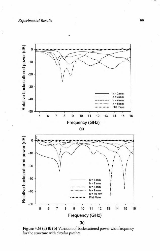
Experimental Results
-aJ 0 " -~ " ~ -10 0 c.
" " ~ -20 " --'" 0 <J)
.>: -30 0
'" .c
" > -40 ., .!!!
" 0:: -50
-aJ 0 " -~ " ~ -10 0 c.
" ~ " -20 --'" 0 <J)
.>: -30 0
'" .c
" > -40 ., '" " 0::
•••• • •••• • ••••••••••••••••••••••••• • ••• ••• ••• •. u..o ...... ~_ ....... 'O\_.~
~- .-.. - .. -----"-.. ~ ~.... .- ... ---
5
5
~ -. ," ...- -,./ ... "\/ -- ............. ---
6
6
"" .. /' _/ ........ - ,-\ '1 ',/1-............... )( /..x...... 'i\........ '... .... - "........ ,/ . / -- '- ,/
7
7
\ ..... ........ -\ I \ I , I J \ . J
8
8
h = 2mm --- h=3mm ------ h=4mm _ .. _ .. _ .. h = 5 mm ••••• •••••• Flat Plate
9 10 11 12 13 14 15 16
Frequency (GHz)
(a)
h=6mm h=7 mm h = 8mm h=9mm h= 10mm
........... Flat Plate
9 10 11 12 13 14 15 16
Frequency (GHz)
(b)
Figure 4.16 (a) & (b) Variation of backscattered power with frequency for the structure with circular patches
99

100 Chapter 4
0 ......... CO "0 '-" l.-Q) -10 3: 0 0.. "0 Q) -20 l.-Q) ::: m C".') rfJ -30 .::tt: C".') m
..Cl Q)
-40 > ~ m Q)
a:: -50
-80 -60 -40 -20 0 20 40 60 80
Angle of incidence (deg) (a)
0 -. CO "0 -l.-Q) -10 3: 0 0-"0 Q) -20 l.-Q) ....... ...... ro C".') rfJ -30 .::tt: C".') ro
..Cl Q)
-40 > ~ m Q) a::
-50 -80 -60 -40 -20 0 20 40 60 80
Angle of incidence (deg)
(b)
Figure 4.17 (b) Backscattered power variations with angle of incidence (a) f=7.77GHz h=5mm (h) f = 13.28 GHz h = 10 mm
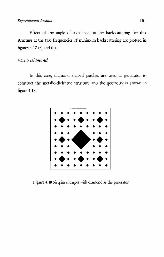
Experimental Results 101
Effect of the angle of incidence on the backscauering for this
structure at the two frequencies of minimum backscauering are ploned in
figures 4.17 (a) and (b).
4.1.2.5 Diamond
In this case, diamond shaped patches are used as generator to
construct the metallo-dielectric structure and the geometry is shown in
figure 4.18.
• • • • • • • • • . +. .+ . . + . • • • • • • • • • • • • • • • . +. .+ . • • • • • • • • • • • • • • • . +. . + . .+ . • • • • • • • • •
Figure 4.18 Sierpinski carpet with diamond as the generator

102
-ID 0 "0 -~ Q)
;. ·10 0
c. "0 ~
·20 Q) ., " U
'" -'" ·30 u
" .0 Q) ." -40 -" Q)
a:: ·50
~ Q) ·20
'iil U
~ U ·30
2: Q) > -40 ., " a;
-J.-., ___ "".~ .... ~ ................................................ ,,~ .::..": _~-::.::~, .. _,,_ .. _, __ ;-__ __ ,_.::::-.:.:.::o--:.-=-
5 6 7
-",',' .... "" ... ---- ,./ '-...... ~, / ' ,," --\.---
8
"" , ---
h=2mm --- h"'3mm ------ h=4mm _ .. _ .. _ .. h '" 5 mm •••••••• ••• Flat Plate
9 10 11 12 13 14 15 16
Frequency (GHz)
<a)
h=6mm h=7mm
------ h=8mm - ,, _ .• _ ... h '" 9mm --- h"10mm •• • •• • ••••• Flat Plate
Chapter 4
a:: .~ L-~------~----~-----r----~----~
6 8 10 12 14 16
Frequency (GHz)
(b)
Figure 4.19 (a) & (b) Backscattered power variations with lrequency lor diflerent substrate thickness lor the sttucture with diamond shaped patches.
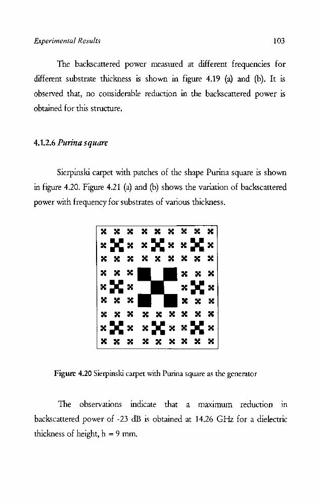
Experimental Results 103
The backscattered power measured at different frequencies for
different substrate thickness is shown in figure 4.19 (a) and (b). It is
observed that, no considerable reduction in the backscattered power is
obtained for this structure.
4.1.2.6 Purina square
Sierpinski carpet with patches of the shape Purina square is shown
in figure 4.20. Figure 4.21 (a) and (b) shows the variation of backscattered
power with frequency for substrates of various thickness.
x X X X X X X X X
XXX XXX XXX X X X X X X X X X
X X X X X X
XXX XXX X X X X X X X X X X X X X X X
XXX XXX XXX X X X X X X X X X
Figure 4.20 Sietpinski carpet with Purina square as the generator
The observations indicate that a maxunum reduction in
backscattered power of -23 dB is obtained at 14.26 GHz for a dielectric
thickness of height, h = 9 mm.
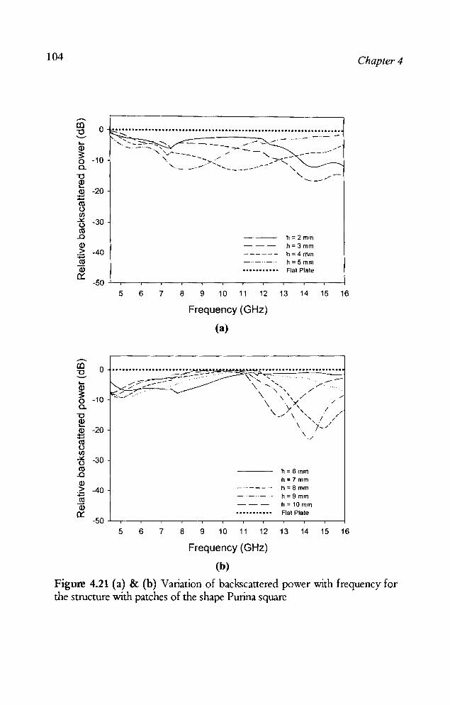
104
.--. CO -C ---.... a> ::!: 0 a.
-C a> .... a> :s:: ro u Cl) ~ u ro .0 a> > :;::::; ro ID a:::
o .................................................................... . ......
-20
-30
-40
5 6 7 8
0
-10
-20
-30
-40
-50 5 6 7 8
_.--_.-" _ .. _ .. _"
h=2mm h = 3 mm h=4mm h=5mm Flat Plate
9 10 11 12 13 14 15 16
Frequency (GHz)
(a)
------- -----...........
9 10 11 12
Frequency (GHz)
(b)
h = 6mm h=7mm h=8mm h=9mm h = 10 mm Flat Plate
13 14 15 16
Chapter 4
Figure 4.21 (a) & (b) Variation of backscattered power with frequency for the structure with patches of the shape Purina square

Experimental Results 105
4.1.2.7 Star
The third iterated stage of the Sierpinski carpet fractal geometry
with patches of the Star shape is shown in figure 4.22.
• • • • • • • • • ••• ••• ••• • • • • • • • • • • • • • • • ••• ••• • • • • • • • • • • • • • • • ••• ••• ••• • • • • • • • • •
Figure 4.22 Sierpinski carpet vvith star as the generator
Since this the structure is not synunetric, the measurements are taken for 1E
and 1M polarization of the incident field. The results are shown in figures
4.23 (a) and (b).
It is observed that for both cases, the maxunum reduction in
backscattered power is obtained for a dielectric thickness of 4 mm.
Variations of backscattered power with frequency is almost identical for
both polarizations.
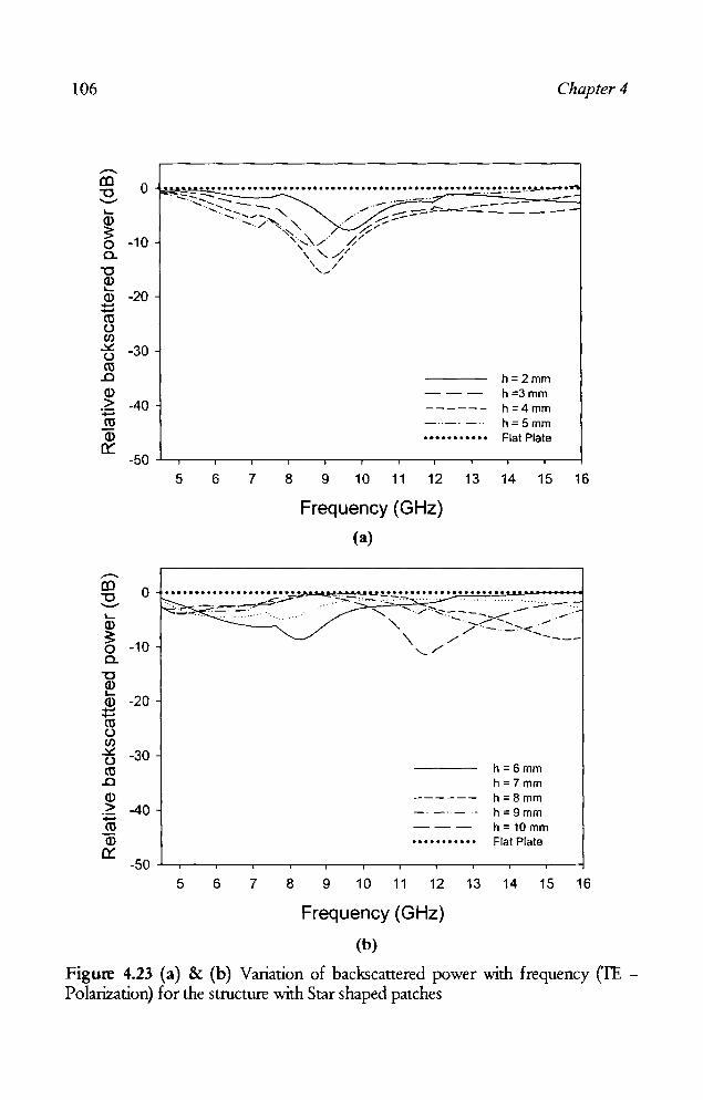
106 Chapter 4
I.-
o ..................... .............................. ~!..!.I!' ................ ...., ""'';::-.:-,:::: - - .. -~." ---
"' ........ ':-::- ~ """ ,""'- -- --~---=-.:::::.:;--- - - - -'''' . ..... ,- /' ........::--........ /"'\.. " . r./,.--" /./ ~ o -10 '\ ..... '\ /' ';;'-\ '- /./ a.
"'0 ~ a.> :t:: Cl) u rJ) ~ u Cl)
..0
a.> > ~ Cl)
a.> n::
.-CO "'0 "-I.-a.> ~ 0 a.
"'0 a.> '-a.> ...... ...... Cl) u rJ) ~ u Cl)
..0
a.> > ...... Cl)
a.> n::
-20
-30
-40
\ / ,~/
h=2mm h=3mm h=4mm h=5mm Flat Plate
-50 -'---,---,---,---,---,---,---,--.,.---.,.---.-----.-----1
5 6 7
0
-10
-20
-30
-40
-50 5 6 7
8
8
9 10 11 12 13 14 15 16
Frequency (GHz)
(a)
h=6mm h =7mm
------ h=8mm -'-'-'- h=9mm --- h=10mm ••••••••••• Flat Plate
9 10 11 12 13 14 15 16
Frequency (GHz)
(b)
Figure 4.23 (a) & (b) Variation of backscattered power with frequency ('lE -Polarization) for the structure with Star shaped patches
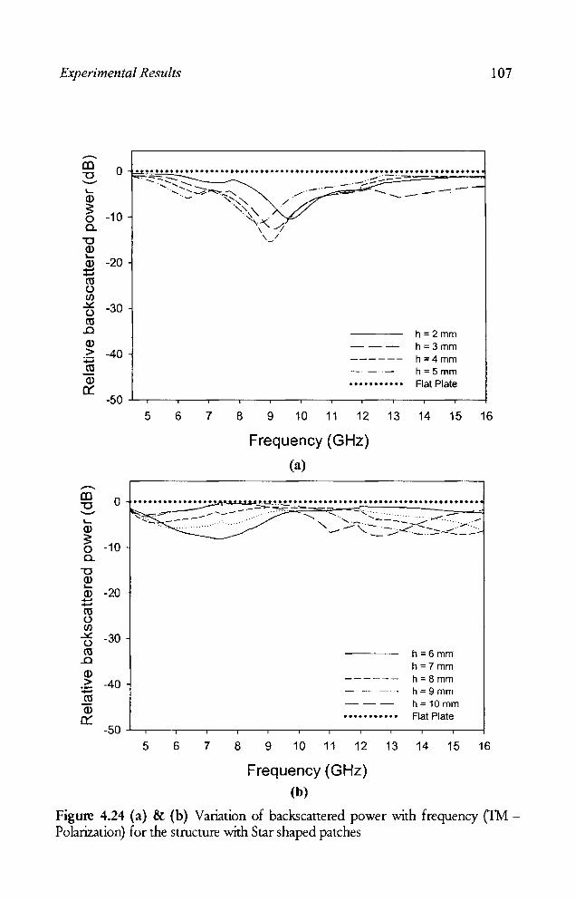
Experimental Results 107
..--.. CC 0 "'C -'-
(J.)
3: -10 0 c..
"'C (J.) "-(J.) -20 :t:: co u If) ~ -30 u co
.J:)
Q) > -40
+=' co Q)
er: -50
-.. CC 0 "'C -'-Q)
3: -10 0 c..
"'C Q) "-ID -20 ..... ..... co u If) ~ -30 u co
.J:)
(J.) > -40 :;:: co Q)
a:: -50
....•••••..........••.•........•...........••••...........••••••..... . ~.:::-- ........... .;,.. .. --.;.;~ :;..,:::-:::~'-==-~~-=--"-==----;
........... ::.~,;::;:.~~-..... .-' - ---: -
5 6
- ~~ / ~~
7
'\" -'-'<../1 \ I ,_/
8 9
h =2 mm --- h=3mm ------ h=4mm -- ---- h=5mm •••• ••••••• Flat Plate
10 11 12 13 14 15 16
Frequency (GHz)
(a)
•••••••• ~~.u...~ •••••••••••• •••••••••••••••••••••••••••••
~~~~~--=-::~-~ ,,~-~=~~~~~-?-:~~-S ~
5 6 7 8
------- .. - -
---.....••....
9 10 11 12 13
Frequency (GHz) (b)
h =6 mm h=7mm h=8mm h= 9mm h = 10 mm Flat Plate
14 15 16
Figure 4.24 (a) & (b) Variation of backscanered power with frequency (1M -Polarization) for the structure with Star shaped patches

108 Chapter 4
4.1.2.8 Cross barfractal tree
Figure 4.25 shows the metallo-dielectric structure based on the
Sierpinski carpet geometry with crossed bar fractal tree shaped patches.
+ + + + + + + + +
+++ +++ +++
+ + + + + + + + +
:+:+:+: + + + + + +
+ + + + + + + + +
+++ +++ +++
+ + + + + + + + +
Figure 4.25 Sierpinski carpet with Crossed bar fraetal tree as the eenerator
From the experimental results shown in figures 4.26 (a) and (b) it is
observed that this structure is not giving appreciable reduction in the
backscattered power.

Experimental Results
..-III 0 "'C '-' .... Q)
~ -10 0 a.
"'C Q) .... Q) -20 --C\l () If)
.Y: -30 () C\l
.J':J Q) > -40 :;:; C\l Q)
a::
.--.
...............................................................••••••
5 6 7 8
h=2 mm h = 3 mm
------ h=4mm _. __ . _ .. h=5mm
••••••••••• Flat Plate
9 10 11 12 13 14 15 16
Frequency (GHz)
(a)
III "'C
o .................................................................... . ...... -::-=-_~c-:~~-.::'O::;~"'=~~~.::i; ____ ~~?:-'-' ....
Q)
~ -10 a.
"'C ~ Q) -20 ~
~ If)
-t5 -30 C\l
.J':J Q)
> -40 :;:; C\l Q)
a::
h=6mm h=7mm
------ h=8mm _ .. - _ ... h=9 mm
--- h=10mm ••••••• •••• Flat Plate
-50 ..L......----r--,---,--.----;--.....,--.---r--.-----,_~
5 6 7 8 9 10 11 12 13 14 15 16
Frequency (GHz)
(b)
109
Figure 4.26 (a) & (b) Variation of backscattered power with frequency for the structure with patches of the shape crossed bar fmctal tree dipole

110 Chapter 4
4.1.2.9 Sierpinski carpet array
Array of second iterated Sierpinski carpet fractal geometry is shown
in figure 4.27.
• • • • • • • • • • • • • • • • • • • • • • • • • • • • • • • • • • • • • • • • • • • • • • • • • • • • • • • • • • • • • • • • • • • • • • • •
Figure 4.27 Array of second iterated stage of Sietpinski carpet
Results of the scattering measurements for this structure are shown in
figure 4.28 (a) and (b). A maximum reduction of backscattered power of -
24.5 is obtained at 8.775 GHz for a substrate thickness of 5 mm.
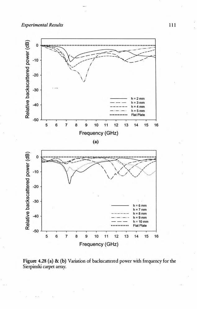
Experimental Results
-ID 0 "0 ~
~
'" ~ -10 0 Cl. "0 ~
-20 Q) = '" ()
'" "'" -30 ()
'" .0 Q) > -40 .,
.J!l Q)
a:: -50
-ID 0 "0 ~
~
Q)
~ -10 0 Cl.
"0 ~
-20 Q) = '" ()
'" "'" -30 ()
'" .0 Q) > -40 ., '" Q)
a:: -50
i"'!!"~' .~.~ •• :.:: •••••.••••..•••••••• .•• ...••.. .................. .......... .. ...... :: ... ~, .-" .. -"
5
.. -~...... .. .. .' _., -.. - .-----',\ -~-- -
6
\ ... ~ ....... -- /_- ---~ ... ~ _---7- "'..::::=. __ .......
':.~-................ ;" I
., I
7 8
\ ./
9
h =2mm - -- h = 3mm ------ h =4 mm - .. - .. - .. h = 5 mm •••• •• •••• • Flat Plate
10 11 12 13 14 15 16
Frequency (GHz)
(a>
•••••• '..!!!' •••••••••• .!!..~ .• """ ...... .! y.!.~~ ~ •• .! ~ ....................... . .... ~............ .. 7'" _~ .... :, . , .' -... , .. ",;"--- ..... >"' . ..., --/ . --...... , \ .'?'" ........ ,....... .... ·.v i·· ... ..... · .\ \/ 'X/ ... //
.... " /" / \/ . ,_ ....
5 6 7 8 9
h = 6mm h=7mm
---- - - h=8mm _ .. _ .. _ .. . h = 9 mm
--- h = 10mm ........... Flat Plate
10 11 12 13 14 15 16
Frequency (GHz)
111
Figure 4.28 (a) & (b) Variation of backscarrered power with frequency for the Sierpinski carpet array.

112 Chapter 4
4.1.3 Sietpinski gasket based metallo-dielectric structure
TIlls section describes the use of Sierpinski gasket based metallo -
dielectric structure for backscattering reduction. Figure 4.29 shows the
metallo-dielectric structure based on Sierpinski gasket.
Figure 4.29 Sierpinski gasket based metallodielectric structure
Backscattering characteristics of this structure is shown in figure.
4.30 (a) and (b). Here, a reduction of up to -31 dB at 8.8 GHz is achieved
for a substrate thickness of 5 mm. Further increase in substrate thickness
gives reduction in backscattering at a lower frequency but with less
bandwidth.

Experimental Results
~
CO 0 "0 ~
~
Q)
~ -10 0
a. "0 ~
-20 Q) --'" u
'" -" -30 u
'" .0 Q) > -40 ., .!!! Q)
er -50
.....................................................................
5 6 7 8
\
\ v -',,;
9
I I
h ::2mm --- h= 3mm - ---- - h=4mm - '- - '--" h = Smm ........... Flat Plate
10 11 12 13 14 15 16
Frequency (GHz)
(a)
o ......... ... ....... ;.:~~":..."!-• ..!~!. ••. ~.~ .~ .~ .~ .•.•. ~ ....................... .
.. :::~ ... ,.. /' ::.:::. .. ):...-.=.\ ..... :, .. :~.-~.:: .-<~::,- ..... / ~~
-10
"0 ~ ~ -20
'" u ~ u
'" .0 Q) > ., '" Q)
er
-30
-40
\\\ ... ./ .... -- ./ '- " ....... , "' " ····7'·~····· :,;,.. . \ -. " . ........ . .... ... -7-.. --,\ \)1,/ / ...... / "" \, .......... -.("'"./ /
5
~"/· .... , .... \ / ~,-..... 'i'· I '-. I , \ .'l /. ' t " I, ', ;
It .. I, ,; ~ "
6 7 8
h =6mm h=7mm h=8mm h=9mm h:: 10mm Flat Plate
9 10 11 12 13 14 15 16
Frequency (GHz)
(b)
113
Figure 4.30 (a) & (b) Backscanering characteristics of Sierpinski gasket based merallo-die1eculc structure.
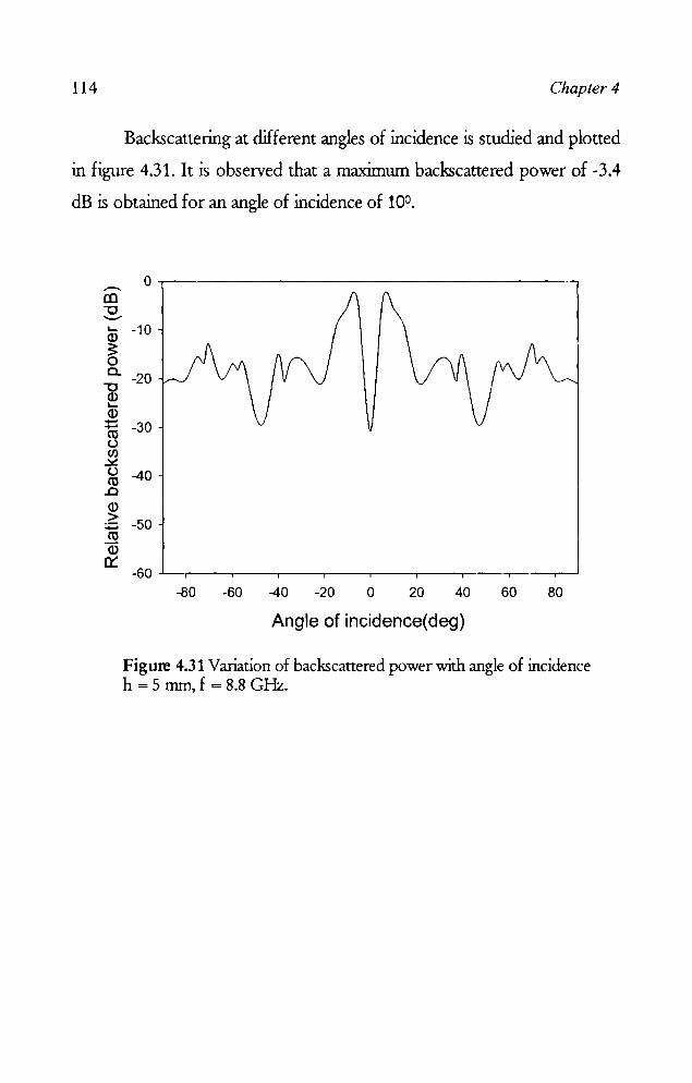
114 Chapter 4
Backscattering at ilifferent angles of incidence is studied and plotted
in figure 4.31. It is observed that a maximum backscattered power of ~3.4
dB is obtained for an angle of incidence of 100.
..-... CO "'0 --... I-
ID ~ 0 a.
"'0 ID l-Q) .... +-' ro
c..> en ~
c..> ro
..0 ID > :.::::; ro ID
er:
0
-10
~20
-30
-40
-50
-80 ~60 -40 -20 o 20 40 60 80
Angle of incidence(deg)
Figure 4.31 Variation of backscattered power with angle of incidence h = 5 mm, f = 8.8 GHz.
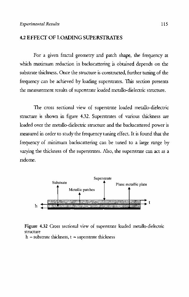
Experimental Results 115
4.2 EFFECT OF LOADING SUPERSTRATES
For a given fractal geometry and patch shape, the frequency at
which maximum reduction in backscattering is obtained depends on the
substrate thickness. Once the structure is constructed, further tuning of the
frequency can be achieved by loading superstrates. This section presents
the measurement results of superstrate loaded metallo-dielectric structure.
The cross sectional view of superstrate loaded metallo-dielectric
structure is shown in figure 4.32. Superstrates of various thickness are
loaded over the metallo-dielectric structure and the backscattered power is
measured in order to study the frequency tuning effect. It is found that the
frequency of minimum backscattering can be tuned to a large range by
varying the thickness of the superstrates. Also, the superstrate can act as a
radome.
Superstrate Substrate Plane metallic plate
Metallic patches
t h
Figure 4.32 Cross sectional view of superstrate loaded metallo-dielectric structure h = substrate thickness, t = superstrate thickness

116 Chapter 4
4.2.1 Supers trate loading on Sierpins ki carpet fractal geometry
The Sierpinski carpet based metallo-dielectric structure is loaded
with superstrates of various thickness (t) and the backscattering is
measured. This is repeated for the structure fabricated on substrates of
different thickness (h).
III '"0
'-Q)
~ 0 0.
"'C Q) '-Q) .... .... ro () Cl)
..::tt! ()
ro .0 Q) > :;::. ro Q) '-
0
-10
-20
-30
-40
. __ ~"-" ___ ............ _'!....~-L:==~~~~~:. .. ~-- ......... "- -,.-- -. .--~- --~-" ..... ----~... .~ .. , -'. ", ", /' \, .... "'. ...... ,/
\ I, " •••••
\ I", / •
\ '. \ ,/ .:' \ '. .~ .'
\ ", ",J", :
\ .} ... : \" . v ~ :'. : : ~ / \! \!
\i ij
t= 0 mm t = 0.6 mm t= 1 mm t = 1.5 mm flat plate
-50+---~--~----~--~--~--~--~----~--~
8 9 10 11 12 13 14 15 16 17
frequency, GHz
Figure 4.33 Variation of backscattered power with frequency with superstrate loading on Sierpinski carpet structure, h = 3 mm.
Results shown in figure 4_33 indicate that as the superstrate
thickness is increased, the frequency giving minimrun backscattering
decreases. The frequency of minimrun backscattering at 13.75 GHz
without superstrate (t = 0) can be shifted upto lOA GHz by loading
superstrate of thickness t = 1.5 nun. Appreciable reduction is obtained at
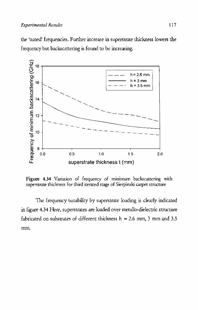
Experimental Results 117
the 'umed' frequencies. Further increase in superstrate thickness lowers the
frequency but backscattering is found to be increasing.
--N I 18~--------------------------------------~ (9
Cl C ·c 16 Cl) ..... ..... ('IJ (.J
~ 14 (.J ('IJ ..c
§ 12 E c
E 10 '+o >-(.J c
"~
.~.
.~. - -.-.
h= 2.6 mm
h=3mm _. __ ... h = 3.5 mm
--- - --- --
Cl) 8+---------~--------~--------~--------~ :::::I C" 0.0 0.5 1.0 1.5 2.0 ~ u. superstrate thickness t (mm)
Figure 4.34 Variation of frequency of nurumum backscattering with superstrate thickness for third iterated stage of Sierpinski carpet structure
The frequency umability by superstrate loading is clearly indicated
in figure 4.34 Here, superstrates are loaded over metallo-die1ectric structure
fabricated on substrates of different thickness h = 2.6 mm, 3 mm and 3.5
mm.

118 Chapter 4
4.2.2 Superstrate loading on Sierpinski gasket [ractal geometry
Effect of superstrate loading is studied on Sietpinski gasket
geometry also . .As before, when the structure is loaded with superstrate, the
frequencies of minimum backscattering are shUted downwards with
increase in superstrate thickness as shown in figure 4.35.
-CO 0 ................ . ................ "0 - ""~~~.~ ... L-
a> 3: ".~ ,",
-10 "I .. , •
0 .~ \ ... c... . \ '. "0 ~ \ ............. "';(.. Q) .~ , ./'. f L- ., .... ---.x I. -_ Q) -20 \-. """ /' I ...... _. " :::: ~ I· 'f:' . ro \/ .". / .1\ I"'~:' u f/) \ . I \ I ., t=O mm
::i! -30 'y .. 1 I ~: t= 1 mm u \ \ I , I .: •.•••.......
ro ___ / . , I ------ t= 2 mm ...c \ .~ ,1 a> / "
--~ .. -.- t= 3 mm > -40
" --- t=4 mm ~ ,t
ro h=5mm ,t --_._.- t=5 mm Q) ~ flat plate 0::
-50 5 6 7 8 9 10 11 12
Frequency (GHz)
Figure 4.35 Power measured for different superstrate thickness on the Sierpinski gasket strucntre
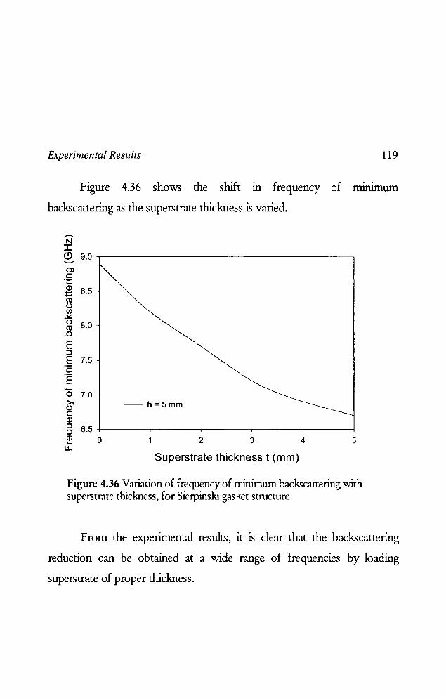
Experimental Results 119
Figure 4.36 shows the shift m frequency of rrurumwn
backscattering as the superstrate thickness is varied .
.--... N I (!) 9.0 ,-----------------------, '-" 0) c ·c ~ 8.5 (\l () Cl) ~
~ 8.0 .0
E :::I E 7.5 'c E '0 7.0 >. () c Q)
-- h=5mm
:::I 0- 6.5 +-----.----....-------,------.--------l
~ o 2 3 4 5 LL
Superstrate thickness t (mm)
Figure 4.36 Variation of frequency of minimum backscattering with superstrate thickness, for Sierpinski gasket structure
From the experimental results, it is clear that the backscattering
reduction can be obtained at a wide range of frequencies by loading
superstrate of proper thickness.
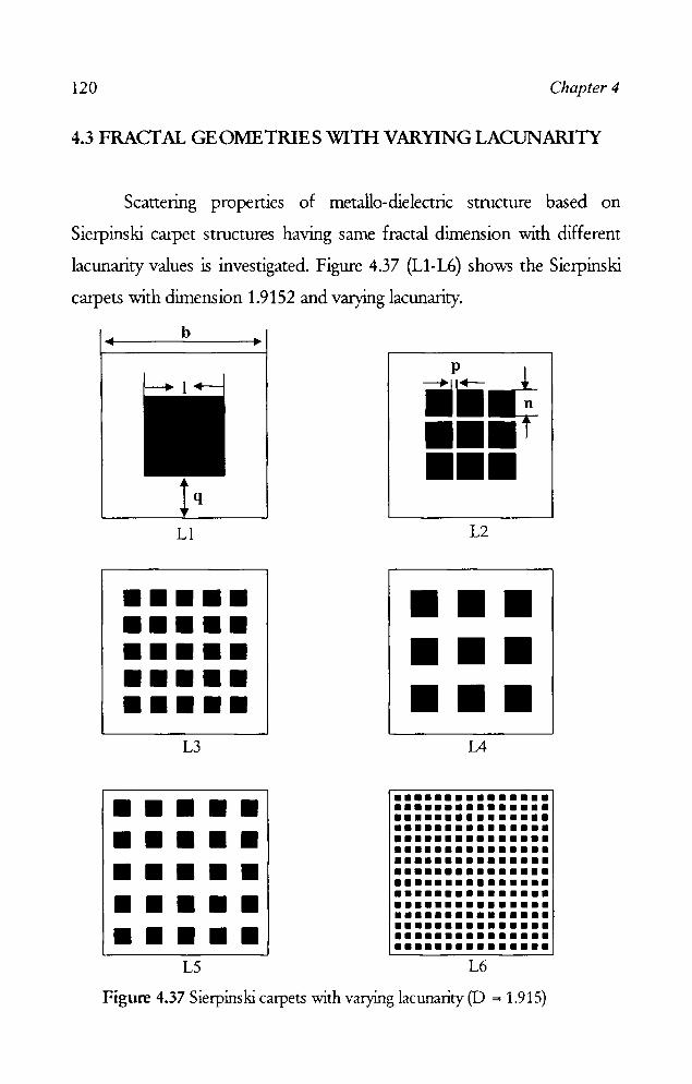
120 Chapter 4
4.3 FRACfAL GEOIvlETRIES WITH VARYING LACUNARITY
Scattering propertIes of metallo-dielectric structure based on
Sierpinski carpet structures having same fractal dimension with different
lacunarity values is investigated. Figure 4.37 (LI-L6) shows the Sierpinski
carpets with dimension 1.9152 and varying lacunarity.
b
LI
••••• ••••• ••••• ••••• ••••• L3
• • • • • • • • • • • • • • • • • • • • • • • • • L5
ii~ •• if 111111
L2
11 11 11 11 11 11 11 11 11
L4
•••••••••••••• •••••••••••••• •••••••••••••• ••••••• ••• •• ••••••• ••• • • ••••••• ••• • • ••••••• ••• •• ••••••• ••• •• ••••••• ••• • • ••••••• ••• • • ••••••• ••• • • ••••••• ••• •• ••••••• ••• •• ••••••• ••• •• ••••••• ••• • • L6
Figure 4.37 Sierpinski carpets -with varying lacunarity (D = 1.915)

Experimental Results
ID ."
o .......................................................... ·UJc· ...... U"O
.- -- '- -- '- '- '-'--- -- '- '- '- -- '- '::---""'- -=---'- --~ ~ o -10 Co
-~,:<, ... ;» :- __ C:·77~"'CC: "0 ....... _'-( /' ~ , /
~ -20 \ /
~ \ / w \,
tj -30 ' ',<C-!_-- Ll(h= 4.5 mm) ~ \ I ... L2(h: 5 mm)
Q) \ t------ L3(h: 7 mm) 1; -40 \ I - -- -- .. . L4{h= 7 mm) ro IJ - - - L5(h= 8.5 mm)
1) _ ._ ._ .- L6(h= 12 mm)
'" , __ ~ __ ~ __ ~_~",,··CC· ·CC··:;·:;··"··--"""'·",';"o'"""'-" ... ,~" -50 ~ 4.5 5.0 5.5 6.0 6.5 7.0 7.5 8.0
Frequency (GHz)
121
Figure 4.38 Variation of backscattered power with frequency for optimum dielectric thickness for carpets with varying Iacunarity in C band
Figure 4.38 shows the variation in relative backscattered power with
frequency in C - band for the structures shown in figure 4.37. The
substrate thickness is varied for each strucrure and the thickness giving
minimum backscattering in the band is found out. A reduction in
backscattered power of 44dB is achieved at 6.46 GHz for a dielectric
thickness h ~ 7 mm for the structure 13. It is also noted that the
backscattered power is below - 20 dB for a wide band of 5 .54 GHz to
6.84 GHz. Similarly, the results of the measurements in X and Ku bands,
are shown in figure 4.39 and 4.40. The backscattered power is reduced up
to - 42 dB at 8.34 GHz and - 44 dB at 15.22 GHz in X and Ku frequency
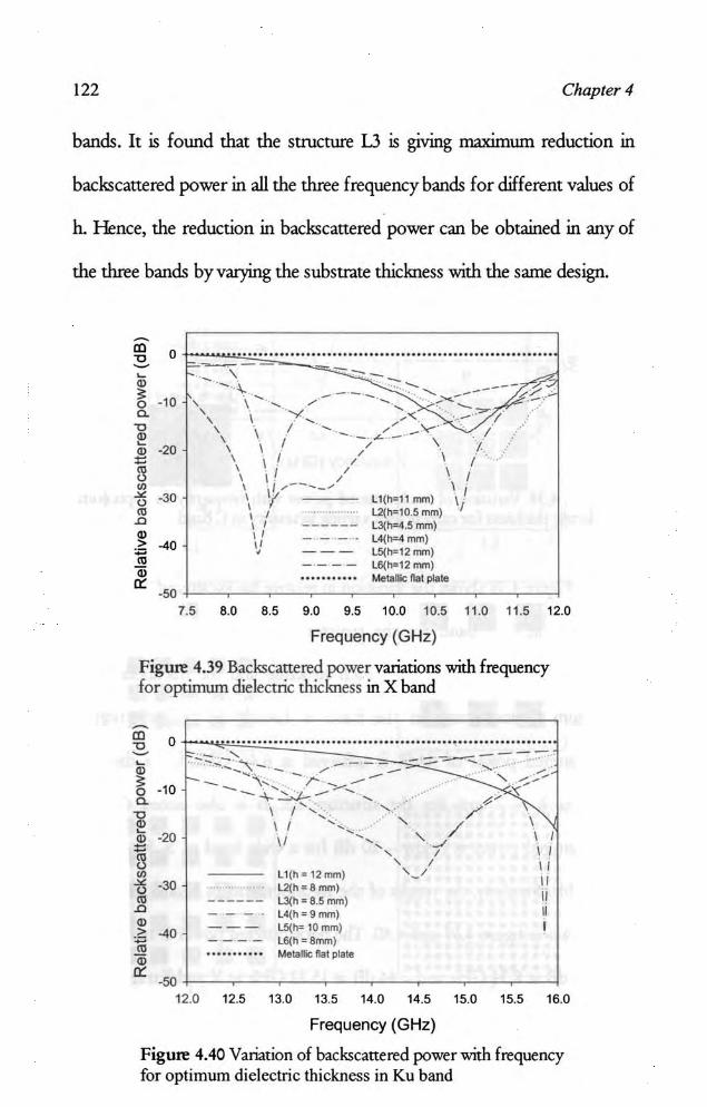
122 Chapter 4
bands. It is found that the structure 13 IS giving maximum reduction in
backscanered power in all the three frequency bands for different values of
h. Hence, the reduction in backscanered power can be obtained in any of
the three bands by varying the substrate thickness with the same design.
ID "0 0 ............................................................ - ---~ " \ ---" -- " l,.. . - -------- /:/ . ~ ----·10
" , -_ ....... - .- -.
0 , , , c. ,
1'- - ,.~.- .:::-/ , \ ........ '<; . "0 ,
\ - -_ L' _ .. -~. / ~ , .,
1 , \ .. -20 , \ / " \ 1
, \ '"
, , 1 1l \ \ ! /
, \ \ , 1 "' , " .... ----'" -" -30 \ Ll(lP:ll nvn)
.. I
" , y 'I '" , , L.2(tF=10.5 mm) .D , , ------ L3(h:4.5 mm)
" , , - - .- ..• L4(h=4 mm) > -40 " "' , --- L5(h=12 mm)
'" ---- l6(h=12 nvn) Qi
'" ........... Metallic flat plate
-50 7.5 • . 0 • . 5 9.0 9.5 10.0 10.5 11 ,0 11 .5 12.0
Frequency (GHz)
Figure 4.39 Backscanered power variations with frequency for optimum dielectric thickness in X band
iil ~ 0 t::;?.~ .. ~ .. ~.~ .. ~ .. ~ .. ~.:: .. : .. : .. ::.; .. ; .. ; .. ~.~ .. ~ .. ; .. ~.~ .. ~ .. ~ .. ~.:. ~ ................. . - r" -~"'::::""- -...- -~:---.-;- . ~o -10 1--- ... "\ .......... - .r ~--- . "x- ,- ~ '~ 'V/' a. -...l,..~-- ............ 6" ~'\
\ , ........ -, -.." /'" ¥ " ---- "/ \ .! -20 \1 .............. ," \ I ...... ~,-f \ I 1l ',_/' \I rh L1(h :12mm) -n -30 L.2(h = 8 mm) 11 ro ______ L3(/'I=S.Srrm) It .0 ___ . L4(/'I:9mm) If ~ -40 --- L5(Iv<,Omm) I ~ - - .- - L6(/'I = Srnrn) Q) • ••••• • •••• Metallic llat plate
'" 12.0 12.5 13.0 13.5 14.0 14.5 15.0 15.5 16.0
Frequency (GHz)
Figure 4.40 Variation of backscanered power with frequency for optimum dielectric thickness in Ku band
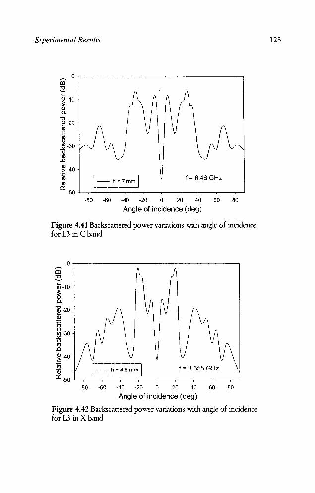
Experimental Results
o,-------------------------------------. --a:l -0 '-" .... ~-10 a. -0 ~-20 Q) ..... ~ ~-30 o m .0
~ -40 :;:; m Q)
0:= 1- h=7mm I f = 6.46 GHz
-50~~--~--_r--_.--_.--_,,_--._--.---~~
~ ~ ~ ~ 0 ~ ~ W ~
Angle of incidence (deg)
Figure 4.41 Backscattered power variations with angle of incidence for L3 in C band
O,-------------------------------------~ --a:l -0 '-"
ID -10 ~ o a.
~-20 .... Q)
::::: ~ en -30
..la:: () m .0
~-40 :;:; m Q)
f = 8.355 GHz
0:=-50~.---~---r---.---.---,----.---.---~~ -80 -60 -40 -20 0 20 40 60 80
Angle of incidence (deg)
Figure 4.42 Backscattered power variations with angle of incidence for L3 in X band
123
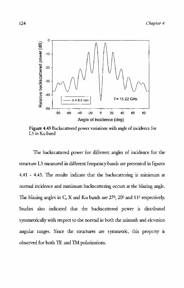
124 Chapter 4
o~----------------------------------. -r.o "0 --.... ~ -10 o Cl.
~ -20 Q) ......
1§ ~ -30 o ttl .0
~ -40 :;J ttl Q)
0:: 1- h=8.5mm 1 f = 15.22 GHz
-50 "'----~--~--_.__--~--_.__--~--_.__--~--....___' -80 -60 -40 -20 0 20 40 60 80
Angle of incidence (deg)
Figure 4.43 Backscattered power variations with angle of incidence for L3 inKu band
The backscattered power for different angles of incidence for the
structure L3 measured in different frequency bands are presented in figures
4.41 - 4.43. The results indicate that the backscattering is minimum at
nonnal incidence and maximum backscattering occurs at the blazing angle.
The blazing angles in C, X and Ku bands are 270, 200 and 110 respectively.
Studies also indicated that the backscattered power is distributed
synunetricallywith respect to the normal in both the azimuth and elevation
angular ranges. Since the structures are symmetric, this property is
observed for both TE and Th1 polarizations.

Experimental Results 125
4.4 RCS REDUCTION OF 3D STRUCTURES
As mentioned earlier, basic building blocks of any complex targets are
flat plates, cylinders, cones and corner reflectors. Result of loading fractal
based metallo-dielectric structure on these objects are described in the next
sectlon
4.4.1 METALLIC CYLINDER
A metallic cylinder loaded with the metallo dielectric structure is
shown in figure 4.44.
• • • •• • . . . .. '----
Dieledric substrata
Metallic patches
Figure 4.44 Hollow metallic cylinder loaded with fractal based metallodielectric structure, L = 30 cm, r = 9.55 cm
The measurements are done for both TE and TM polarization of
the incident field for vertical and horiwntal orientation of the cylinder for
different angles of incidence.
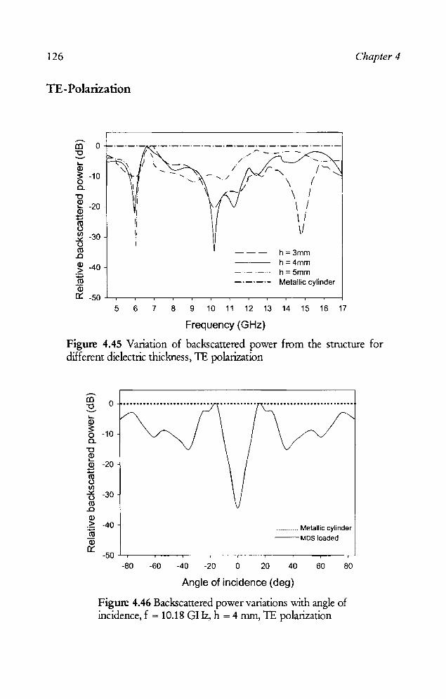
126 Chapter 4
TE-Polarization
.--. CD 0 "0 --~ Q)
:s: -10 o Cl.
-g ~ -20 Q)
~ ~ -30 (.) co .0
~ -40 :;::; co Q)
./ i
./
r_____ /'->... \ ( \ / \ I \ / \1
--- h=3mm h=4mm
-.- ._ .. - h = 5mm --_._.- Metallic cylinder
0:: -50 -'----r_-.--~---r--.-----,--__,____,-___,__-r__._-.,...__l
5 6 7 8 9 10 11 12 13 14 15 16 17
Frequency (GHz)
Figure 4.45 Variation of backscattered power from the structure for different dielectric thickness, 1E polarization
.--. CD -0 ---~ ~ o -10 0.. "0 ~ 2 -20 -co (,) If)
t5 -30 co .0 Q) _~ -40 (ij Q)
0:::
.......... _ Melallic cylinder --MDS loaded
-50~--.--__,_--.----,--.--___,__-~--~
-80 -60 -40 -20 o 20 40 60 80
Angle of incidence (deg)
Figure 4.46 Backscattered power variations with angle of incidence, f = 10.18 GHz, h = 4 mm, 1E polarization
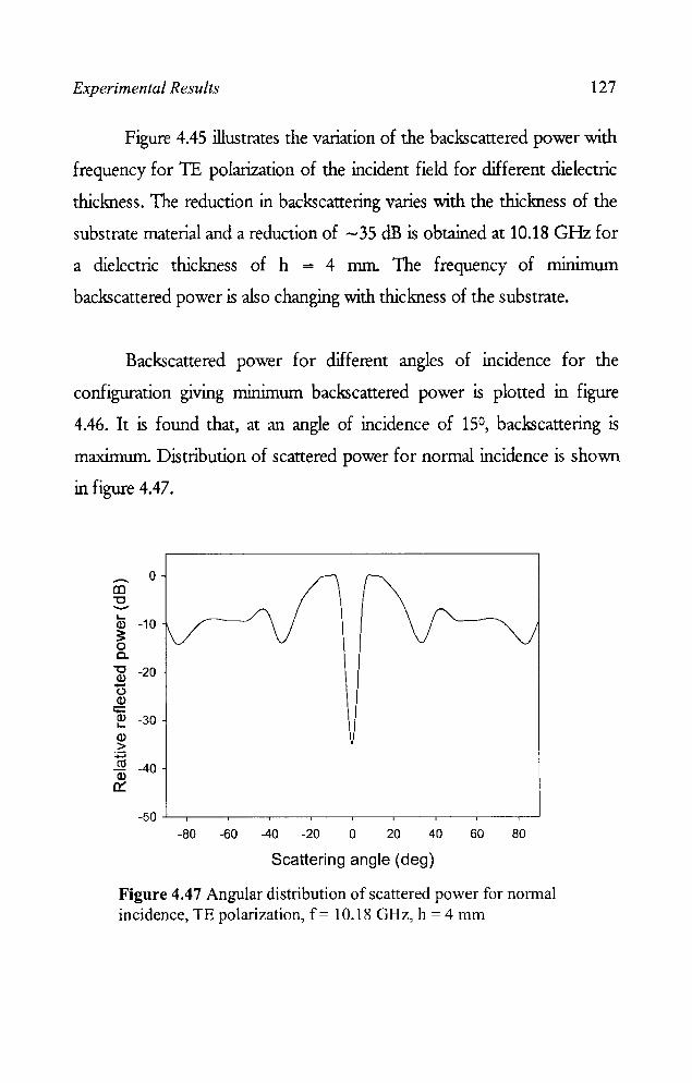
Experimental Results 127
Figure 4.45 illustrates the variation of the backscattered power with
frequency for 1E polarization of the incident field for different dielectric
thickness. The reduction in backscattering varies with the thickness of the
substrate material and a reduction of - 35 dB is obtained at 10.18 GHz for
a dielectric thickness of h = 4 mm. The frequency of minimum
backscattered power is also changing with thickness of the substrate.
Backscattered power for different angles of incidence for the
configuration giving minimum backscattered power is plotted in figure
4.46. It is found that, at an angle of incidence of 15°, backscattering is
maximum Distribution of scattered power for normal incidence is shown
in figure 4.47.
_ 0
co "'C ........-.... Q) -10 ~ o a. ~ -20 t5 Q)
1i5 -30 '-Q) >
:;::; ca Q) -40
a:: -50 -'----.-----.---_.__-_.__-_.__-~-_.__-~-..,..__J
-80 -60 -40 -20 0 20 40 60 80
Scattering angle (deg)
Figure 4.47 Angular distribution of scattered power for nonnal incidence, TE polarization, f = 10.18 GHz, h = 4 mm
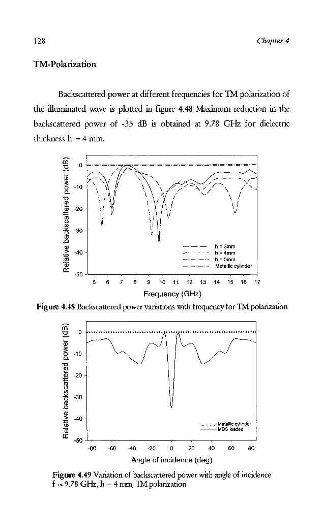
128 Chapter 4
TM-Polarization
Backscattered power at different frequencies for 1M polarization of
the illuminated wave is plotted in figure 4.48 Maximum reduction in the
backscattered power of -35 dB is obtained at 9.78 GHz for dielectric
thickness h = 4 mm.
o '--Q.l
~ -10 c.. "0 ~ Q.l -20 -~ f/)
t5 -30 cc
..0 Q.l £; -40 cc Q.l 0::
h=3mm h=4mm h=5mm Metallic cylinder
5 6 7 8 9 10 11 12 13 14 15 16 17
Frequency (GHz)
Figure 4.48 Backscattered power variations with trequency tor 1M polarization
......... ID -0 o· .................................................................... .. --..... Q.l
~ -10 c.. "0 Q.l L-
Q.l -20 ;:
~ f/)
tj -30 cc
..0 Q.l ~ -40 cc Q.l
...... ..... Metallic cylinder --MDS loaded
0:: -50 -'--r--.-----.----.-----.--.-----.-----r------,---' -80 -60 -40 -20 o 20 40 60 80
Angle of incidence (deg)
Figure 4.49 Variation of backscauered power with angle of incidence f = 9.78 GHz, h = 4 mm, 1M polarization
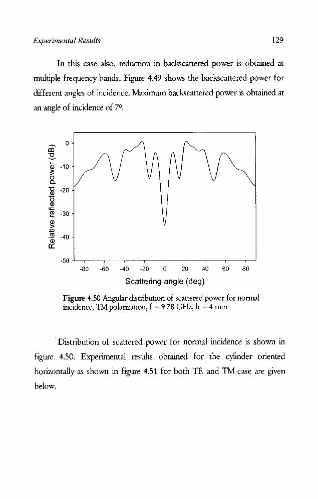
Experimental Results 129
In this case also, reduction in backscattered power is obtained at
multiple frequency bands. Figure 4.49 shows the backscattered power for
different angles of incidence. Maximum backscattered power is obtained at
an angle of incidence of 7°.
.-... co "'0 '-" L-
a> ~ 0 Co
"'0 a> -u a>
;;:::: a> L-
e]) > :;::::; et)
a> 0::
0
-10
-20
-30
-40
-80 -60 -40 -20 o 20 40 60 80
Scattering angle (deg)
Figure 4.50 Angular distribution of scattered power for nonnal incidence, 1M polarization, f = 9.78 GHz, h = 4 mm
. Distribution of scattered power for nonnal incidence is shown in
figure 4.50. Experimental results obtained for the cylinder oriented
horizontally as shown in figure 4.51 for both TE and TM ·case are given
below.

130 Chapter 4
Figure 4.51 Fractal structure loaded cylinder, horizontally oriented
TE -Polarization
0 -al "'C --L-a> -10 ~ 0 c..
"'C a> -20 L-a> ...... ...... ro () (/) -30 ~ () ro
..0
a> -40 > :;::: ro a>
0::: -50~--~----~--~----~----~----~----~~
-60 -40 -20 o 20 40 60
Angle of incidence (deg)
Figure 4.52 Variation of backscattered power with angle of incidence f = 9.78 GHz, h = 4 mm, TE polarization
The graph of vanatlon ill backscanered power with angle of
incidence for the frequency giving minimum backscanered power and
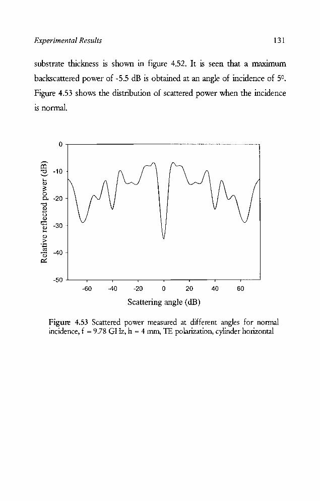
Experimental Results 131
substrate thickness is shown in figure 4.52. It is seen that a maximllil1
backscattered power of -5.5 dB is obtained at an angle of incidence of 5°.
Figure 4.53 shows the distribution of scattered power when the incidence
is nonnal.
---o:l "0 '-" I-< Q)
~ 0 0..
"0 Q) ...... u Q)
4: Q) I-< Q)
.~ ...... ro .-Q)
~
0
-10
-20
-30
-40
-50 -60 -40 -20 0 20 40 60
Scattering angle (dB)
Figure 4.53 Scattered power measured at different angles for nonnal incidence, f = 9.78 GHz, h = 4 mm, lE polarization, cylinder horizontal
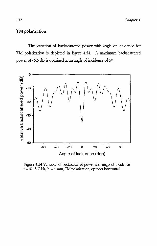
132 Chapter 4
TM polarization
The variation of backscattered power with angle of incidence for
1M polarization is depicted in figure 4.54. A maximum backscattered
power of -6.6 dB is obtained at an angle of incidence of 50.
0 --!Xl "'0 --L-
a> -10 ~ 0 Cl.
"'0 a> -20 L-
a> ....... ....... co C,) Cl) -30 ~ C,)
co ..c a> -40 > :;::::. co a>
0:: -50~--.-----.---~----~----.---~-----,--~
-60 -40 -20 o 20 40 60
Angle of incidence (deg)
Figure 4.54 Variation of backscattered power with angle of incidence f =10.18 GHz, h = 4 nun, 1M polarization, cylinder horizontal

Experimental Results 133
Figure 4.55 shows the distribution of scattered power when the incidence
is nonnal.
......... (() "0 --I.... Q)
~ 0 c..
"0 Q)
....... {) Q)
'+= Q) I....
Q)
> ....... rn Q)
n::::
0
-10
-20
-30
-40
-50~--~----.---~----~----~----.---~--~
-60 -40 -20 o 20 40 60
Scattering angle (deg)
Figure 4.55 Scattered power measured at different angles for normal incidence, f = 10.18 GHz, h = 4 mm, TM polarization
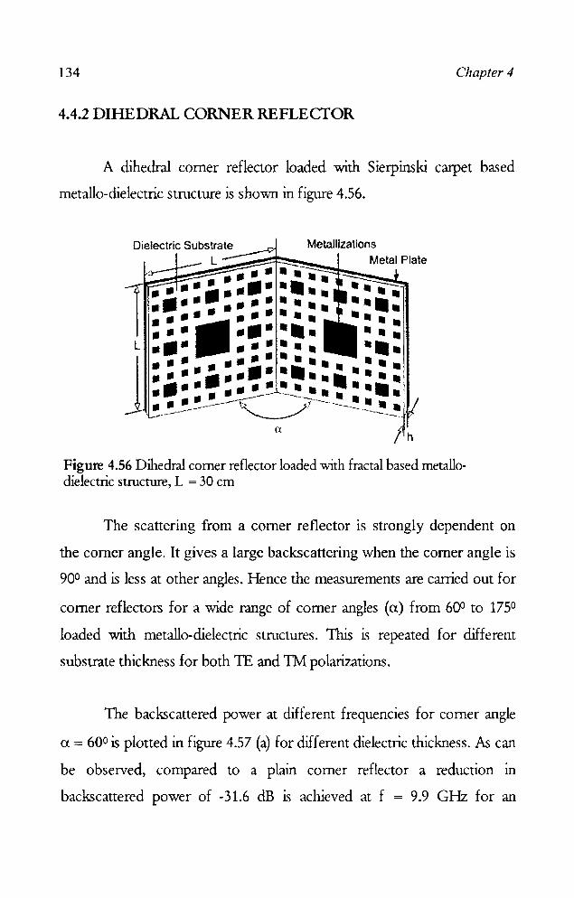
134 Chapter 4
4.4.2 DIHEDRAL CORNER RE FLE CfOR
A dihedral corner reflector loaded with Sierpinski carpet based
metallo-dielectric structure is shown in figure 4.56.
Dielectric Substrate Metallizations L Metal Plate ..............
•••••• III •• ...
•••• • ••••••• ..... ...... . 11·· ..... .. L ••• ....... • ••
••• •••••••••• ••• ..... .•..•. .... ...... . ••• •••••• • •• . . . .. . . .. ••• • ••• . - . Figure 4.56 Dihedral corner reflector loaded with fractal based metallodielectric structure, L = 30 cm
The scattering from a corner reflector is strongly dependent on
the corner angle. It gives a large backscattering when the corner angle is
900 and is less at other angles. Hence the measurements are carried out for
corner reflectors for a wide range of corner angles (a) from 600 to 1750
loaded with metallo-dielectric structures. This is repeated for different
substrate thickness for both TE and TM polarizations.
The backscattered power at different frequencies for corner angle
a = 600 is plotted in figure 4.57 (a) for different dielectric thickness. As can
be observed, compared to a plain corner reflector a reduction in
backscattered power of -31.6 dB is achieved at f = 9.9 GHz for an

Experimental Results 135
dielectric thiclmess of h = 2 mm. It is also obselVed that there IS an
increase in backscauering (3.96 dB) at f = 8.5 GHz compared to a plane
corner reflector. The measurements are repeated for different acute angles
of the corner reflector and the results for TE polarization are shown in
figures 4.57 (a)-(f). 10,--------------------------------------. -co
"0 ....... L.. 0 •••••.•••••........• • ~ . ......... . Cl) //, .
3: // \ \ I / o 11' \/ . C. , ' . 'J '
"0 -10 \ \. /~::;. '/ \ ~ " \ I \ \ \ I
~ I \1 '1\ I Cl) \ I \\1, " i: :::: -20 , : \~ , " I ~ 'I'~' I: w l ~ \ ~ -30 I .0
~ :;:::; -40
--- 2mm - - 3mm --- 4mm
", " , ,
ro a::: 600 •••••• Plain dihedral corner Cl)
0:::
5 6 7 8 9 10 11 12 13 14 15 16
Frequency (GHz) (a)
20.---------------------------------------~ .-III "0 -:- 10 Cl)
3: " -" r:/ 0c. 0 ~o.&&,o~, "!..!." •••••••••••••••••••••••••••••••••••••• ~' ....
" ./. '- / " '
~ '-.. ..... \ '- -10 \\ 2k ~ I U) -20 \1 ~ (.)
~ -30 Cl) > ~ -40 Cl)
0:::
--2mm 3mm 4mm Plain dihedral corner
------
5 6 7 8 9 10 11 12 13 14 15 16
Frequency (GHz) (b)
Figure 4.57 Variation of backscattered power against frequency for acute angles of the dihedral corner reflector for TE polarization (a) a = 60° (b) a = 65° , ...................... contd
136 Chapter 4
L... (],) ;: o c.. -0 ~ (],) ~
10
o
C\l -10 () (f)
.::&:. ()
C\l ..0 (],) > ~ C\l Q)
Cl:::
..-[l) -0 --L... (],) ;: o c.. -0 (],) L... (],) ~ C\l () (f)
.::&:. () C\l
..0 Q) > ~ C\l Q)
Cl:::
-20
-30
-40
20
10
0
-10
-20
-30
-40
-50
'\ / 1-4, / .. '..
.~ J i\ / \ £,-~, ./ \. .. /
_...a...:c.~.~~~~~,I' •• ,- .•••• ~... ~.\ •••••••• / ••••••• "rI.~ .....
-- h=2mm h=3mm h=4mm
~ ,\ I -......" . \ .:, . .f '\ I . / J \" , !- \ I I. ',\ " ~ I I
11 11 11 I
Plain dihedral corner a:::: 700
5 6 7 8 9 10 11 12 13 14 15
Frequency (GHz)
(c)
."""'
-- 2mm 3mm 4mm a=750 Plain dihedral corner
5 6 7 8 9 10 11 12 13 14 15
Frequency (GHz)
(d)
16
I
16
Experimental Results
20.-------------------------------------------~ ..-.. CO "'C .......... L-
a> 10 ~ o a..
"'C ~ 0
~ ro c.> Cl) -10 ~ t)
ro .0
~ -20 :.;::::l ro a> 0::
~, .......
h=2mm _. - _ .. h=3mm
------ h=4mm
\ i J
./ \.
• •••••••••• Plain dihedral corner
/ /
<X= 800
-30~.---.---._--r__,--_,--_,--_,--_.--_.--_.--~
5
20 ..-.. CO "'C .......... 10 L-a> ~ 0 0 a..
"'C
~ -10 a> :::: ro t) -20 Cl) ~ t)
ro -30 .0
a> > ~ -40 J2 a>
0:: -50
5
6 7 8 9 10 11 12 13 14 15 16
Frequency (GHz) (e)
/ .. ---- ...... .;: ...... \ ..... ................. ~~ ... ,~ ..... ~ .. . /' \ .. / // ..
-- h=2mm h = 3 mm h =4 mm
\ k~ ."\ / / \ / \ '\ 'I, (\ / / \I. . \ '" "'. . . 1\ /.\.:v /'- I
\ . \ I \! ,1\.\ I \ ·It/ J \, \ I : 1
" \1 \: ~ ,I \1 ,I
~ i i
Plain dihedral corner
6 7 8 9 10 11 12 13 14 15 16
Frequency (GHz)
(f)
137

138 Chapter 4
It is observed from figure 4.57 (a) - (f) that there is an enhancement in
backscattering at certain frequencies for corner angles in the range
60° - 85°.
In the case of 900 plain dihedral corner reflector, a large RCS is
obtained due to the multiple reflections from the two mutually orthogonal
flat surfaces dominating the backscattered pattern .. TIlls is reduced when
the metallo-dielectric structure is loaded over the flat surfaces .
...-.. m '0 o ...•....•.••..................•..•.•.............•.•................. -"-ID
~ -10 a. '0 ~ ID -20 ~ co u U)
TI -30 co .0
ID ~ -40 co ID
0:::
, .......... , , , .. , '._ .. , :..-~ '--' ~ .J)..
." /T I·~ \ '/ \ I , .. \, "-\ I \ ' \. /' " \' \ \"
I' 'to
-- h=2mm h=3 mm h=4 mm
" \ I j \ J I 1/
~
Plain dihedral corner
" " / /
/
.'. \
/,,-----
\ I
\ . . , \.
/
I
---
5 6 7 8 9 10 11 12 13 14 15 16
Frequency (GHz)
Figure 4.58 backscattered power variations against frequency for a right angled dihedral corner reflector, 1E polarization
The variation of backscattered power with frequency for corner
angle ex = 900 is shown in figure 4.58 for different dielectric thickness. A
maximum reduction in backscattered power of - 32.8 dB is achieved at f =
9.05 GHz for substrate thickness h = 4 mm. It is clear that by loading
Experimental Results 139
metallo-dielectric structures, the back scattered power is reduced to a
considerable extend for ex. = 90°.
o~----------------------------------------~ ..-CO "'0 -L-
a> -10 ~ o 0..
"'0 ~ -20 a> ::::: CO u en -30 ~ u CO ..c
~ -40 +::
CO a>
a::: -50~--~----~----~----~--~----~----~--~
-60 -40 -20 o 20 40 60
Angle of incidence (deg)
Figure 4.59 Backscattered power variations with angle of incidence for f =
9.05 GHz, TE polarization
Backscauered power measured for different angles of incidence for
the dihedral corner with corner angle 900 loaded with the metallo-dielectric
structure of thickness h = 4 mm at f =9.05 GHz is shown in figure 4.58. It
is observed a maximum backscauered power of -3.43 is obtained for an
angle of incidence of 400•
The backscauered power measurements for obtuse angles (<Y = 950
- 1750) are shown in figure 4.60 (a) - (q) for different dielectric thickness.

140 Chapter 4
o ·····················r··.~ ............................ ;~..!....~~ ••••• . - " '( \ _/ ---'-
Q)
~ -10 c..
"0 ~ Q) --~ (,,) In
.::s:. (,,) tU ..c Q) > :p tU Q)
n::
..-... CO "0 -..... ~ Q)
~ 0 c.. "0 Q) ~ Q) --~ (,,) In
.::s:. u ~ ..c Q) > :p ~ Q)
n::
-20
-30
-40
20
10
0
-10
-20
-30
-40
-50
'\ '.__ A\: ./ .... ../'....... .,_, ---- ........... ".'\ ( \r· ./ \/'~- ......--
5
\~ i l \ /'\ /"1·-'
~ /1 "'\ l ~ \ I .\ \ ' \ I \ I
. \ ' \ 1 .\ I ' I I :
I IJ 1_
I U 11
I -- h=2mm
h=3mm h;:;;4 mm
...... Plain dihedral corner
6 7 8 9 10 11 12 13 14 15 16
-- h;:;;2mm h=3mm h=4mm
Frequency (GHz)
(a)
et = 1000
...... Plain dihedral corner
5 6 7 8 9 10 11 12 13 14 15 16
Frequency (GHz) (b)
Figure 4.60 Variation of backscattered power against frequency for obtuse angles of the dihedral corner reflector for TE polarization (a) a = 95° (b) a = 100° ....................... contd
Experimental Results 141
30 --a:J "'C 20 --l-Q)
3: 10 0 c..
"'C /
Q) 0 ,/
l-Q) - -10 -ro () Cl) ~ -20 C,.) ro ..c
-30 Q) -- h=2mm > :;:::::l h=3mm ~ -40 h=4mm Cl = 1050 Q)
0::: ...... Plain dihedral corner -50
5 6 7 8 9 10 11 12 13 14 15 16
Frequency (GHz)
(c)
20 --a:J "'C --l-Q) 10 ~ 0 c..
"'C Q) 0 l-Q) --ro () Cl) -10 ~ () ro -- h=2mm ..c Q) h=3mm > -20 h =4mm :;:::::l
Cl = 1100 ro Plain dihedral corner Q.)
0::: -30
5 6 7 8 9 10 11 12 13 14 15 16
Frequency (GHz)
(d)

142 Chapter 4
20 .-CO "'0 .......... L... 10 Q) ,. ;! 0 0. 0
"'0 ~ Q)
+-' -10 +-' ro () (/) ~ () -20 ro .0 Q) -- h=2mm >
:0:; -30 h = 3 mm Cl = 1150 ro h =4 mm ID
0::: Plain dihedral corner -40
5 6 7 8 9 10 11 12 13 14 15 16
Frequency (GHz) (e)
15 .-CO "'0 10 .......... L... Q)
;! 5 0 0.
"'0 0 Q) '...-L... Q) A
+-' -5 .' ,
+-' /, ro --() \i..fI r (/) \ , ~ -10 \J () ~ ro .0
-15 Q) h = 2mm .~ h=3mm If +-'
Cl = 1200 ro -20 h=4 mm Q3 0::: Plain dihedral corner
-25 5 6 7 8 9 10 11 12 13 14 15 16
Frequency (GHz)
(f)
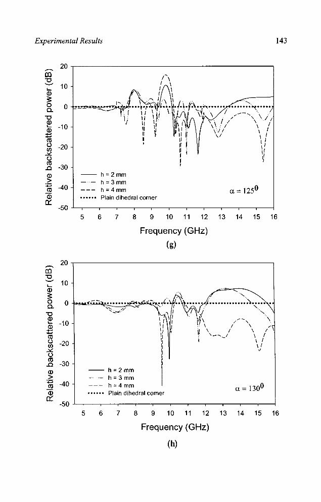
Experimental Results 143
20 ..-CO "'0 -- 10 ~
ID ~ 0 0 a.
"'0 ID
-10 ~
ID .... .... tU u -20 t/) ~ U tU
-30 ..c ID -- h=2mm > h=3mm :;::; -40 tU h;::;4mm ID Plain dihedral corner
0::: -50
5 6 7 8 9 10 11 12 13 14 15 16
Frequency (GHz)
(g)
20 ..-CO "'0 -- 10 ~
ID ~ 0 0 ~,;-- •••••••• ,,~ltr. a. :.....':::;:~ ........ </. "'0 "-ID --~ -10 / , ID / \ .... I \ .... '--_I \ tU u -20 \ I t/) \ I ~ " U tU
-30 ..c ID -- h;:::2mm > h;:::3mm
:;::; -40 h;:::4mm a = 1300 tU ID Plain dihedral corner
0::: -50
5 6 7 8 9 10 11 12 13 14 15 16
Frequency (GHz)
(h)

144 Chapter 4
10 --CO "'C
'- 0 Q)
~ 0 0.. -10
"'C
~ Q) 1) ....... -20 .......
'/ ca (J L tIJ I ~ 1: (J -30 0/ ca .0 -~ h=2mm Q) h=3mm > :;::: -40 h=4 mm
(l = 1350 ca Plain dihedral corner Q)
0::: -50
5 6 7 8 9 10 11 12 13 14 15 16
Frequency (GHz)
(i)
10 --CO "'C
'- 0 ... Q)
~ 0 0.. -10
"'C
~ Q) .......
-20 ....... ca (J tIJ ~ (J -30 ca .0 -- h=2mm Q) h = 3 mm > -40 h =4 mm :;:::
(l = 1400 C\l Plain dihedral corner Q)
0::: -50
5 6 7 8 9 10 11 12 13 14 15 16
Frequency (GHz)
(j)
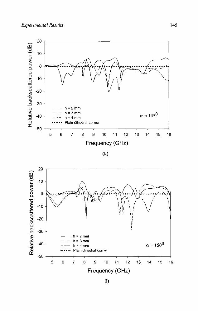
Experimental Results 145
20 --CO "'0 -- 10 L-Q)
~ 0 0 c..
"'0 Q)
-10 L-Q) ...... ...... et! t.) -20 Cl) ~ t.) et!
-30 .0 Q) h =2mm > h =3mm
a. CC! 1450 :;:; -40 et! h=4 mm
Q) Plain dihedral corner 0:::
-50 5 6 7 8 9 10 11 12 13 14 15 16
Frequency (GHz)
(k)
20 --CO "'0 -- 10 L-Q) /
~ 0 0 ........ /-;-.")~. c..
" / \ "'0 Q) '/ \ I \ L.. -10 \ I \ Q) \ I \ ...... \. \ ...... et! t.) -20 Cl) ~ t.) m
-30 .0 Q) -- h=2mm > h= 3mm :;:; -40 a = 1500 m h=4mm Q) Plain dihedral corner
0::: -50
5 6 7 8 9 10 11 12 13 14 15 16
Frequency (GHz)
(I)

146 Chapter 4
20 ..-c:n -0 ---L- 10 a)
~ 0 a.
0 -0 a) L-a)
........ -10 ........
ro u Cl) ~ U -20 ro .0 a) -- h=2mm > -30 h = 3mm
+=' ro a = 1550 h =4 mm
a) Plain dihedral corner 0:::
-40
5 6 7 8 9 10 11 12 13 14 15 16
Frequency (GHz) (m)
20 ..-c:n -0 ......... 10 L-a)
~ --- -;-.;:. --;;: .. : .;.' 0 0 .... ...... a. . ~ ,
\ \j , \ / -0
\ \ //1\--/--a) L- -10 \ .1 / \.1 a)
\ \ / \ ........ ........ \ I .. ro
\ Iv " u -20 If Cl) ~
, f
U
" ro -30 " .0 II
a)
I h =2 mm > :p -40 h = 3mm
a c:= 1600 ro h =4 mm a)
0::: Plain dihedral corner -50
5 6 7 8 9 10 11 12 13 14 15 16
Frequency (GHz)
(n)
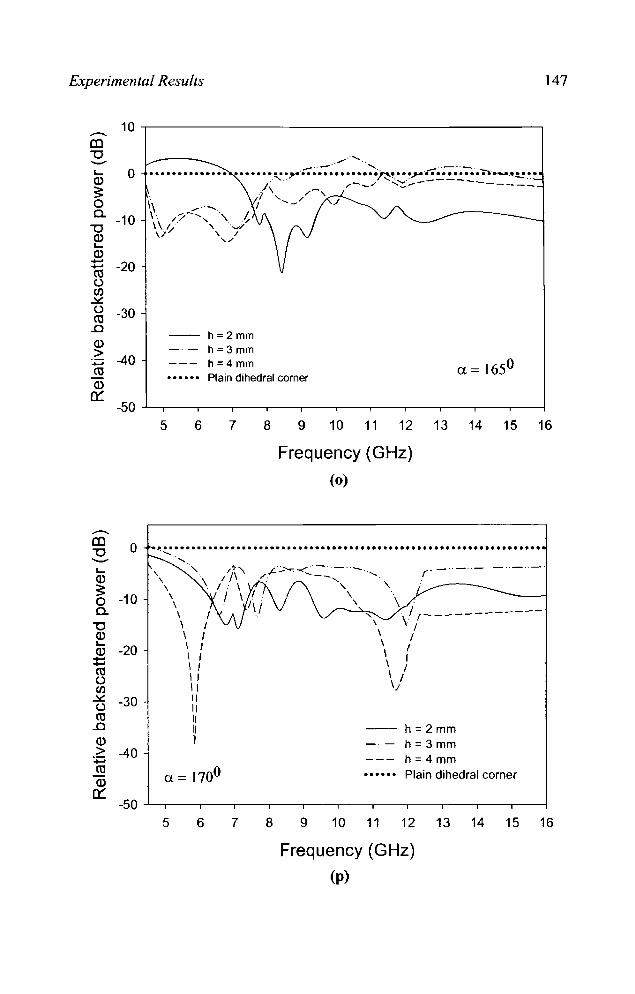
Experimental Results 147
-. CC "'0 '-" I-a> ~ 0 a.
"'0 a> I-
a> +-' +-' C13 Q Cl) ~ Q C13
..0
a> > ....... ro a> n::
-. CC "'0
----l-Q)
~ 0 a.
"'0 Q) I-a>
+-' +-'
C13 Q Cl) ~ Q et!
..c Q) >
:j:J et! a> n::
10.-------------------------------------------,
0
-10
-20
-30
-40
___ .. _ .. /....................... ..,,--.0-•••••••••••••• •••••••••• ,.,.. .•••••••••••••• ~~ ••• "...'r. •••••••. ~ .... _ .• .!..! .••
/............. /-_/ ',;::."::,.----------- . 1', /,-,
1\ ....-........ . I .... -I //- .... ,', ? \ \ I ,~; ,,/ 'I ,/
h =2 mm h = 3 mm h =4 mm Plain dihedral corner
-50 -.l....-,---..---y------;r-------.-----r----,------r-----r------.-----.-----j
0
-10
-20
-30
-40
5 6 7 8 9 10 11 12 13 14 15 16
Frequency (GHz)
(0)
.................................................................... ......
, \
\ \
5
\ \ \ \ I \ I \ I 1 I
" 11 11 11
11
I
6 7 8 9
r' -"-"- ._ .. _ .. -'
\ '
/ r------------\ /
/ I I
I / 1/
-- h=2mm h = 3 mm h =4 mm Plain dihedral corner
10 11 12 13 14 15 16
Frequency (GHz)
(p)

148 Chapter 4
..-(Q ~ 0 ••••••••••••••••••••.•...•••••.••••••••••••••.••••••••.•.....•••••••••
-20
-30
-40
-- h ;;2mm h;;3mm h=4mm Plain dihedral corner
-50 -'---,----.---r---.----.--------,,------,----,-~--.-----.--l
5 6 7 8 9 10 11 12 13 14 15 16
Frequency (GHz)
(q)
From the observations it is found that loading fracta! based
metallo-dielectric structure reduces the backscattering from a corner
reflector of corner angle 900• For other angles, an enhancement in
backscattered power is observed compared to a plain corner reflector. The
backscattered power is maximum for cenain acute and obtuse angles. An
enhancement in backscattered power of around 20 dB is obtained for
corner angles a = 800 and 105°.

Experimental Results 149
TM polarization
The measurement results for acute angles of the corner reflector for
1M polarization are shown in figures 4.61 (a) - (t).
IlJ "0 .........
: /._', o ~ • •••••••••••••••••••••••••••••••••••••••••••••••••••••• 'I ........ .
.. \ L-
a> ~ o a. "0 a> L-a> :::: co C,) !J)
.!le: C,)
co .0
ID > :.:::; ro a> 0::
\ . ,.....~ /
'j
, / , I
-- h=2mm h=3mm h=4mm
\ I \ I / \ 1 \ I \ 1 \ / \1 \ I tJ \ /--./
\ I \ I \ I \ 1 \1 \1 \1 V
Plain dihedral corner
\ \
/--
-50~.---r--.---.---.--~--.---.---r--.---.--~
5 6 7 8 9 10 11 12 13 14 15 16
Frequency (GHz) (a)
10 ,-------------------------------------------, .-IlJ "0 ---L- 0 a> ~ o a. -10 "0 a> L-
a> ..... ro -20 u !J) ~
u -30 ro ..0 a> > :;::::; -40 ro a>
0::
h=2mm h=3mm h=4mm Plain dihedral corner
-50 ~,---,---.---.---.---.---.---.---.---.---.-~
5 6 7 8 9 10 11 12 13 14 15 16
Frequency (GHz) (b)
Figure 4.61 Variation of backscattered power against frequency for acute angles of the dihedral corner reflector for 1M polarization (a) a = 600 (b) a = 650
..................... contd
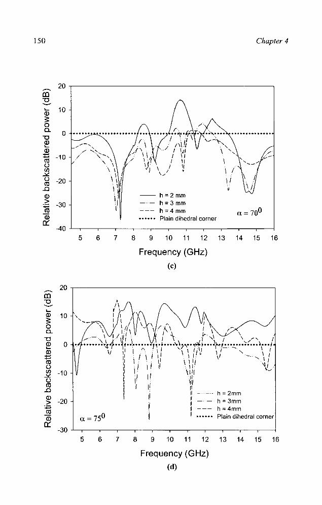
150
20 .-ca "'0 --L... 10 Q.)
~ 0 a.
0 "'0 Q.) L... Q.) .-
-10 ....... CO U (j) ~ u -20 CO ..0 Q)
.2: -30 .-CO Q.)
er: 5 6 7 8
-- h=2mm h =3 mm h =4 mm Plain dihedral corner
Chapter 4
9 10 11 12 13 14 15 16
Frequency (GHz)
(c)
20 .-------------------------------------------~ .-ca "'0 --L...
• 1\ ,
Q.)
~ o
10 ", 1 I / \ ( --, 1 1 / \ \ ~ I
a. "'0 Q) L... Q.) ~ co ()
(j) -10 ~ u co
..0 Q.)
> :p co Q.)
er:
-20
\ 1 I It ~ \ /', \ J /-\ I J \ I .\" Jr. \ \
....... _, \ J/\~I \ . J \\ ./' "\ f \./', f •••••. ···...f.~r··' ~. -:- ....•• T'· ~ ••• ·\"~·i"'\·· .,.~ ~ •••• \~.,~~ -:...- ••••••••••• #
5 6
\/ I' \ .". : \ , \ \ I J IJ I I" \ I 11 : I \ / I' 1 '.. \1 .~." \ I
7
I' \: .. I' \ , , J . I I' ./ \ I 1I . ". ~/. , \: \\11 ~--'I \1" I· \1/ J \1 [/
11 11 . 11
I j . I
h=2mm h=3mm h=4mm
I I Plain dihedral corner
8 9 10 11 12 13 14 15 16
Frequency (GHz)
(d)
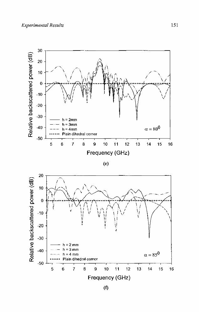
Experimental Results 151
30 ~------------------------------------------~ -CO ~ 20 l-Q)
~ 10 o c.
/"".
. ./ \ I
\ I
-- h=2mm h=3mm h =4mm
/~
,
\
\/
\ / \ I \ I \.
a=800 Plain dihedral corner
5 6 7 8 9 10 11 12 13 14 15 16
Frequency (GHz)
(e)
20~------------------------------------------~ -CO "'C ':' 10 Q)
~ c. o
"'C
~ -10 Q)
::::: co o Cl)
.::s:. <.) co
..0 Q) >
:;::; co Q)
0:::
-20
-30
-40
I \
v
-- h=2mm h = 3mm h =4 mm
\ / \ I \ I \ / \ 1 \1 11 11 11 ,
\ \ (\ 1 1/ \ I 1/ \ I
11 11 11 I
a = 850 Plain dihedral corner
5 6 7 8 9 10 11 12 13 14 15 16
Frequency (GHz)
(f)

152
--. CO "'0 -~ Q)
o
~ -10 c..
"'0 ~ ~ CO o Cl) ~ (.) ro ..c Q)
> :;:::; CO Q)
0:::
-20
-30
-40
5 6 7 8
-- h=2mm h = 3mm h=4mm
Chapter 4
Plain dihedral corner
9 10 11 12 13 14 15 16
Frequency (GHz)
Figure 62 Backscatter power variations against frequency for a right angled corner reflector for TM polarization
As in the case of TE polarisation, 900 corner reflector glves
backscattering reduction when loaded with metallo-die1ectric structures.
Results plotted in figure 62 indicates a reduction of - 40 dB at 8.03 GHz
forh =4 mm.
Backscattered power measured for different angles of incidence for
1M is given in figure 4.63.lt is observed a maximum backscattered power
of -12.27 dB is obtained for an angle of incidence of 15°.
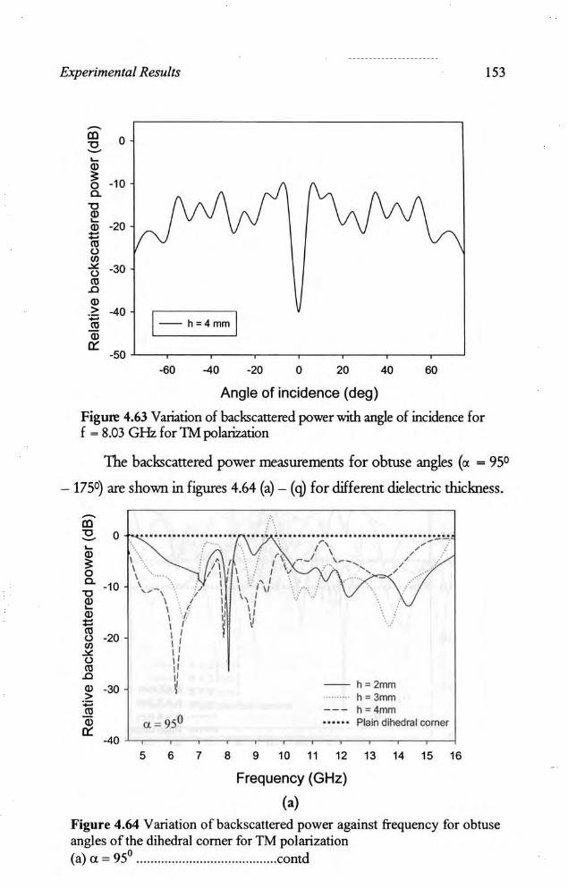
Experimental Results
-'" 0 "0 -~ Q) ;:
·10 0 a. "0 Q) ~
·20 Q)
'" '" ()
"' ~ ·30 ()
'" .Cl Q) > -40 l-h= 4mm l ., '" Q)
0:: ·50
·60 -40 ·20 0 20 40 60
Angle of incidence (deg)
Figure 4.63 Variation of backscattered power with angle of lncidence for f - 8.03 GHz for 1M polarization
153
The backscattered power measurements for obtuse angles (a - 95'
- 175') are shown in figures 4.64 (a) - (q) for different dielectric thickness.
j \ o \. ••••. .......... : .~.:.~. .. . ... , ............ ;~ .................... ;;. . ..:.!. \ \'" " " /\: /' /rr \ . : /I/ ~. j l\-- / \ ' · 'I'I ,: IV .~ ...... . \ 1 I ;: .. I ""'-, ir 1 I' / \/ , ..... : \/ 1 \'/ .; ... .. 1:/ lJ I, ',. ~ ~ 1 I I 1 I I I
"
'. ' .. :
" " ~ -- h ::2mm
....... h ::3mm h::4mm Plain dihedral comer
5 6 7 8 9 10 11 12 13 14 15 16
Frequency (GHz)
(a)
Figure 4.64 Variation of back scattered power against frequency for obtuse angles of the dihedral corner for TM polarization (al et - 95' .......................... ..... ......... contd
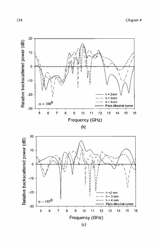
154 Chapter 4
20 .--.. (() "'C --L-Q) 10 ~ 0 0-
"'C Q) 0 L-Q) --ctI t) Cl) -10 .::£ t) ctI
..0 Q)
-20 -- h=2mm > :;::::; h=3mm ctI Q) a = 1000 h=4mm
0::: Plain dihedral corner -30
5 6 7 8 9 10 11 12 13 14 15 16
Frequency (GHz)
(b)
20 .--.. (() "'C --L-Q) 10 ~ ." 0 ..... -, 0- \
\ "'C \/ Q) 0 .. ~ .,}' ~ ..... \_. L- . 1\ Q) - \. -- . I ctI \ . t) CIJ -10 : I
.::£ \ . t) r ctI \.
..0 / Q)
-20 > :;::::; h = 3 mm ctI
Q) a = 1050 h=4 mm 0::: Plain dihedral corner
-30 5 6 7 8 9 10 11 12 13 14 15 16
Frequency (GHz)
(c)
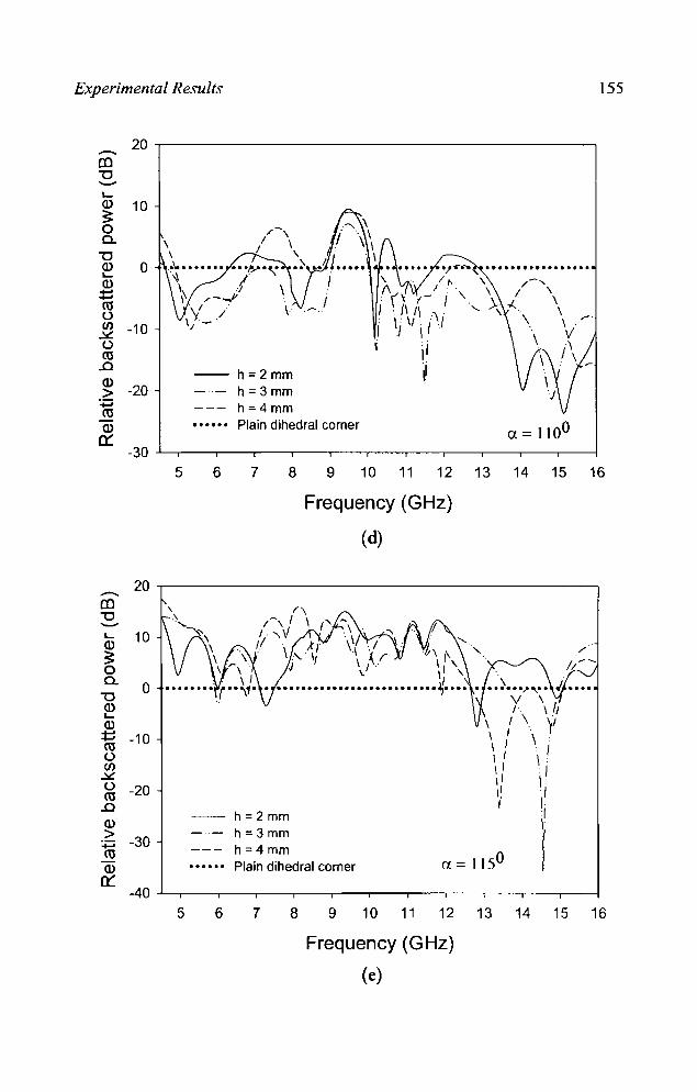
Experimental Results 155
20 -ro "'C .......... L-Q) 10 ~ 0 a.
"'C Q) 0 . ..... .,..-...... . ................ L-
\ / l-Q) +-' (\ / .. +-' : (' ,- i \. ro , : II 11 . .. u . 1· 11: .11 Cl) -10 I " l' .Y. U I ro I .0 -- h;:;2mm ~ Q)
> -20 h;:;3mm :;::; h;:;4mm ro Q) Plain dihedral corner a = 1100
0::: -30
5 6 7 8 9 10 11 12 13 14 15 16
Frequency (GHz)
(d)
20 -ro "'C .......... L- 10 Q)
~ 0 a. 0
"'C Q) L-Q) +-' -10 +-' ro u Cl)
.Y. u -20 ro .0
-- h;:;2mm Q)
> -30 h;:;3mm
:;::; h;:;4mm ro a= 1150
Q) Plain dihedral corner 0:::
-40 5 6 7 8 9 10 11 12 13 14 15 16
Frequency (GHz)
(e)
156 Chapter 4
30~-----------------------------------------. --CO "0 -- 20 L-
a> :?: 10 o 0. "0 a> L-
a>
o
::: -10 re () Cl) ~ ()
re -20
..0 a> -30 .~ -re a> ~
-40 a = 1200
5 6 7 8
f \
'/ \ ..... ~ ... , ......... . \ J \ J \
-- h=2mm h = 3mm h =4 mm
••• ••• Plain dihedral corner
9 10 11 12 13 14 15 16
Frequency (GHz)
(1)
30 ~------------------------------------------~ --CO "0 -L-
a> 20 :?: o 0. "0 ~ 10 a> --re () (/) 0 ~ () re
..0 a> .~ -10 -re a> ~
-- h=2mm h=3mm h =4 mm Plain dihedral corner
-20 ...L.-,----.-----,-----,------,----,----,------.------,----,------r------i
5 6 7 8 9 10 11 12 13 14 15 16
Frequency (GHz)
(g)
Experimental Results 157
20 -,-----------------------,
10 \
~
U= 1300
-- h=2mmh =3mmh =4 mmPlain dihedral corner
/~\ ~\I \ / \
v··...,\,/x -\/ \/.r., \,I
/
LI r~ \ 1\, I \ f
r \' .. .o ..... 1•••••••.•• .• •••"I.. ••••••••,.. •• l,
"1/\ . A;. \ \ ...\.~. \ I ) ',/ \\ . I .
IV I\ II'I'V
-20
L-Q)
~Cl."0~:§roo~ -10oro..cQ)>:;::::roQ)
0::-30 .L-,_____,-~--r-_,__-,_____,-~--r-_,__-,__--1
5 6 7 8 9 10 11 12 13 14 15 16
Frequency (GHz)
(h)
20 -,------------------------,~
m"0~
L-
Q) 103:oCl."0~ 0Q)::::rooI/l -10
.l<:oro..c~ -20
:;::::roQ)
0::
-- h=2mmh=3mmh =4 mmPlain dihedral corner
\\ I
-30 -"--,__---,~__,_--r-__,_-,_____,-__,_-__._-__,_-.__--1
5 6 7 8 9 10 11 12 13 14 15 16
Frequency (GHz)
(1)
158 Chapter 4
20 .-ca "'0 --L- I' a> 10 3: 0 c..
"'0 a> 0 L-
a> ........ ........ ro () /1 .. (/) -10 ·v:/ \ ~ I I \ () \ I ro It ..Cl If a> -20 11 h =2 mm > 11 h::: 3 mm :;::; H ro 11 h;;;4 mm a> ,
Plain dihedral corner a = 1400 0:::
-30 5 6 7 8 9 10 11 12 13 14 15 16
Frequency (GHz)
(j)
30 .-ca "'0 --L- 20 a> 3: 0 c.. 10
"'0 a> L-
a> ........ 0 ........ ro () (/)
..!C: (.) -10 ro
..Cl
a> > -20 -- h=2mm
:;::::; h=3mm ro
a> --- h;;;4mm a = 1450 0::: • ••••• Plain dihedral corner
-30 5 6 7 8 9 10 11 12 13 14 15 16
Frequency (GHz)
(k)
Experimental Results 159
20.-------------------------------------------~
'-Q)
:: o a.
10
,./ X 6 I \ / \
"0 ~
~\ J -- \ {-o ..................... ~··t}.······ .. ). . .. ~ .. ,. .. -.~ .................. . \ -,: ...... _-------<:::...--:---ID t:: ro U ,-/ (f) -10 ~ u ro
..0 Q) > :.;:::; ro Q)
~
-20 h=2mm h=3mm h=4mm
\ I -,J ...... __ - '. "., .........
\ / \1
Plain dihedral corner -30~.---.---.__,,__,---,---.--_,--_,--_r--_r--~
5 6 7 8 9 10 11 12 13 14 15 16
Frequency (GHz)
(I)
30 ~--------------------------------------------. -m "0 -'-Q) 20 :: o a. "0 ID "-ID t:: ro
10 ".." -... ..
/;. ...... -/ "-
/; '" u (f) ~ u
-~/ \~ \ I o ~.4)"tI············l·r-·
ro ..0
~ -10 -ro
~
, 11 11 V
r, / \ 1-\
'/ ~ \--\/'t-, ,,_ "
- \ y/ ~.' . -- -.' ,/~ / ------ /
\. / - ---, : ................... -l.\.; ............. . \..
h = 2 mm h=3mm h =4 mm Plain dihedral corner
-20 ~.---._--.-_,---,---.--_,---,--_r--_r---,--~
5 6 7 8 9 10 11 12 13 14 15 16
Frequency (GHz)
(m)

160
30 -CO "'C
20 ----L-(1)
3: 10 0 C.
"'C 0 ~ (1) +-' -10 +-' ca C,,) (IJ ~ -20 C,,) ca .0
-30 Q) > ~ ca -40 Q)
~ -50
Chapter 4
,/'" ./ ..... " ... """ "
\ t~\ ~( \ ': \ /
\1 \ I 1/
---I:'" ......... --v';" : .............. "" ,:. • .J ..... ~~ """"""
\/
h=2mm h=3mm h =4mm Plain dihedral corner
5 6 7 8 9 10 11 12 13 14 15 16
Frequency (GHz)
(n)
20 ,-----------------------------------------------, -CO "'C ':" 1 0 (1)
3: o C.
"'C
~ ~ ca C,,)
~ C,,) ca ..c Q) > ~ ca Q)
~
o
-10
-20
-30
-40
--\ \ \ "
I ' \ \..,- -'-.
~ .• -!. ~ ,"" "" " " """ """ ""t."" "" """"".t •• ,""""""" """" ..... " """" """ "" "" " -", ..-'7"- . "~'. --./'-" :
- - _ ..... , / ~ \1/ \ I .... / / \'
\ . \ I \ ) \ 1 \1 \1 11 \1
I
I I""----~.... _ \ I '..-"- -----\1 \)
-- h=2mm h =3 mm h = 4 mm Plain dihedral corner
-50 ~._--._--._--._--.__.--_.--_.--_.--_.--_.--~
5 6 7 8 9 10 11 12 13 14 15 16
Frequency (GHz)
(0)
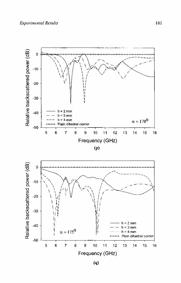
Experimental Results 161
..-CO 0 .- •.••••••••••.•........................... ""C .... --- ,." ---------" .. .... '- ,
\\ -- .. Q) ..... -- .--3: \ \ ...-0 -10 \ /
a. \ \ I . \ I
\ J I ""C ,1\ : . I Q) : I \. '- -20 \. Q) +J +J ro () (/)
.::£ -30 () ro
..0 Q)
h =2mm > -40 :.0:; h=3mm ro
h=4mm Q)
0:: Plain dihedral corner Cl = 1700
-50 5 6 7 8 9 10 11 12 13 14 15 16
Frequency (GHz)
(p)
o .................................................................... . '-Q)
~ -10 a.
""C
~ Q) -20 :t:: ro () (/)
.::£ () ro
..0 Q) >
:.0:; ro Q)
0::
-30
-40
, " , ,
\ , . , \ \
\ \ 1"-- 1/ . \ .f \ \., I
\1, \ \, . ~,
\ 1\) \ j \,
I
I , 'i ~ Cl = 1750
5 6 7 8 9
.... ' -- .... /' --------/ -....
/ " \ --. _. - .. \
.",.,
-- h=2mm h; 3 mm h;4 mm Plain dihedral corner
10 11 12 13 14 15 16
Frequency (GHz)
(q)

162 Chapter 4
In the case of 1M polarizations also it is found that loading fractal
based metallo-dielectric structure reduces the backscattering from a corner
reflector of corner angle 90°, There are enhancements in backscattered
power for certain acute and obtuse angles. Maximum increase ill
backscattered power is observed for corner angles a = 80° and 120°,

Experimental Results 163
4.4.3 CIRCULAR CONE
The scattering characteristic of a circular metallic cone loaded with
metallo-dielectric structure based on the array of Sierpinski carpet fractal
geometry is described in this section. A schematic of the structure is shown
in figure 4.65.
Metallic patches
Direction of incidence
III
Figure 4.65 Metallic circular cone loaded with array of Sierpinski carpet fractal geometry, radius = 11 cm, L = 22 cm.
The variation of backscattered power with frequency for different
substrate thickness is shown in figure 4.66. A plain metallic plate having
the same area as that of the base of the cone is used as the reference target.
The measured results indicate that by loading fractal based structure over
the cone the backscattered power can be reduced to a considerable extent.
A maximum reduction in backscattered power of 25.5 dB with respect to
metallic cone is obtained at f = 8.1275 GHz for a dielectric thickness h =
1.2 mm.
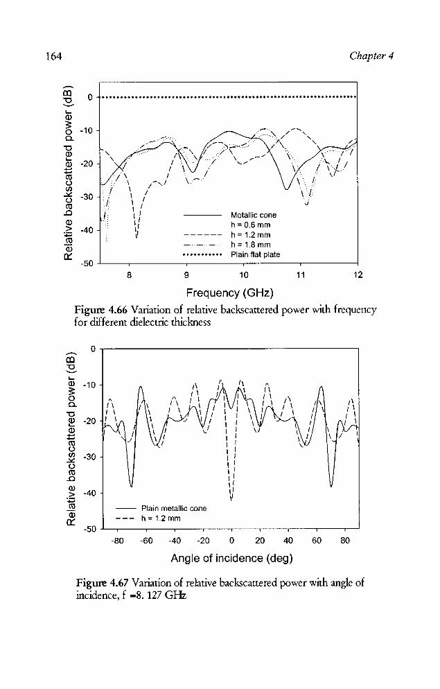
164 Chapter 4
o ..................................................................... . ~
ID
~ -10 c..
"'0 ID ~
ID -20 t: CO u
/\ :. \
(/) .::s:. u CO .0
/ \ -30 J \
ID >
:.::; CO ID 0::
I -40
Metallic cone h= 0.6 mm h = 1.2 mm h = 1.8 mm Plain flat plate
/
\/1
/\1/ . ... \' \. /' \/' ."
-50 -'------,--------,---------.------.------l
8 9 10 11 12
Frequency (GHz)
Figure 4.66 Variation of relative backscattered power with frequency for different dielectric thickness
o ,-----------------------, ......... CO "'0 ""~
ID -10 ~ o c..
"'0 ~ -20 (]) t: CO u ~ -30 u CO .0
~ -40 :.::; CO ID 0::
-- Plain metallic cone h=1.2mm
-80 -60 -40 -20 o 20 40
Angle of incidence (deg)
60 80
Figure 4.67 Variation of relative backscattered power with angle of incidence, f =8. 127 GHz
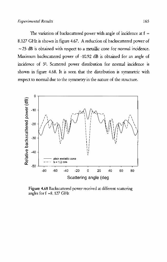
Experimental Results 165
The variation of backscattered power with angle of incidence at f =
8.127 GHz is shown in figure 4.67. A reduction of backscattered power of
- 25 dB is obtained with respect to a metallic cone for normal incidence.
Maximum backscattered power of -10.92 dB is obtained for an angle of
incidence of 5°. Scattered power distribution for normal incidence is
shown in figure 4.68. It is seen that the distribution is symmetric with
respect to normal due to the symmetry in the nature of the structure.
o ~--------------------------------------~ -. CD "'0 '--" L-
a> -10 ~ o c..
"'0 ~ -20 a> ....... ....... co t.)
~ -30 t.) co .0
~ -40 :;::; co a>
0:: -- plain metallic cone --- h=1.2mm
-50~.----.----.---.----.----.---~---.----.-~
-80 -60 -40 -20 o 20 40 60 80
Scattering angle (deg
Figure 4.68 Backscattered power received at different scattering angles for f =8. 127 GHz

Chapter 5
SIMULATION STUDIES AND ANALYSIS
Comparisons of the backscattering properties of d!f[erent structures are
presented in this chapter. The results of the experimental studies are
validated by analyzing the structures using electromagnetic simulation
software. The simulation and experimental results are compared for
different structures.

Simulation Studies and Analysis 169
5.1 BACKSCATTERING CHARACTERISTICS OF STRUCTURES
WITH PATCHES OF DIFFERENT SHAPES
Sietpinski carpet structures with third iterated stages were fabricated
with generators of different shapes and their characteristics were studied in
detail in the previous chapter.
Table 1 presents the comparison of backscattering characteristics of
different structures in ~ X and Ku frequency bands. From the table, it is
clear that by using fractal structures the reduction in backscattered power
can be obtained at different bands. Sietpinski carpet with circular patch as
the generator is giving backscanering reduction over a bandwidth of 3
GHz (below -10 dB) in the C band. A bandwidth of 3.37 GHz is obtained
for the structure with hexagonal patch as the generator in the X band. In
Ku band, 3.1 GHz bandwidth is obtained for square Sietpinski carpet
structure.

170 Chapter 5
Table 1 Comparison of backscattering properties of different fractal structures
-10 dB Bandwidth ( GHz) Fractal structures
C-band X-band Ku-band Sierpinski carpet 0.46 2.4 3.1 Square TE & TM Cross TE & TM 0.21 1.15 1.48
Octagon 0.6 1.95 2.52 TE&TM Hexagon 1.03 1.14 1.44 TE-polarization Hexagon 0.7 3.37 1.64 TM-polarization Circle 3 1.71 2.8 TE&TM Diamond TE & TM - 1.22 1.64
Purina square 0.7 2.66 3 TE&TM Star - 1.6 0.l3 TE - polarization Star - 1.25 -TM - polarization Sierpinski carpet 1.05 1.05 1.12 Array TE & TM Sierpinski gasket 2.58 2.6 1.8 TE and TM

Simulation Studies and Analysis 171
5.2 SIMULATED RESULTS
The different iterated stages of Sietpinski carpet (shown in figures
4.1 - 4.4) were studied for the structures fabricated on substrates of
different thickness. The optimum thickness giving minimum backscattered
power in the band is found out. Simulation using CST Microwave Studio
showed that the structure with the third iterated stage of Sietpinski carpet
gives maximum reduction in backscattered power. The simulated results
are shown in figure 5.1 (a). Experimental results shown in the previous
chapter is repeated in 5.1 (b) for comparison.
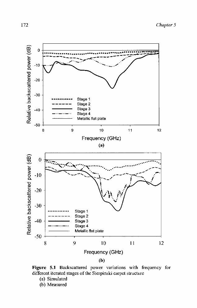
172 Chapter 5
.-.. ID "'0 -L-
o +-----------------------------------~~~~=d ................•.....••...•......•.••..••. ~::~~ .. ~~~~ ------._--.... ...------_ ... --- . .". ...
Q)
~ -10 a.
"'0 Q) L-Q) ::::: ro u r/)
...lI:: U CO .0 Q) >
:t;j ro Q)
Cl:
-20
-30
-40
-'-" ,/ .................. _.. ...... ........ _ ........
••••••••••• Stage 1 Stage 2 Stage 3 Stage 4 Metallic flat plate
-50 +----------.----------~----------.---------~ 8 9
.-..
10
Frequency (GHz) (a)
11 12
ID "'0 o ~~------------------------------~~ ... :...... ,. --L-Q)
~ o -10 a.
"'0 Q) L-
Q) -20 ::::: ro u If)
t5 -30 ro .0 Q)
.;:: -40 -ro Q)
Cl: -50
8
......... (': . ~ ... -, '.' ...... ,. ..''''.......... . ............ . ........ . ....
Stage 1 Stage 2 Stage 3 Stage 4 Metallic flat plate
9 10
Frequency (GHz)
(b)
11 12
Figure 5.1 Backscattered power vanatlOns with frequency for different iterated stages of the Sierpinski carpet structure
(a) Simulated (b) Measured

Simulation Studies and Analysis 173
Figures 5.2 (a) to 5.2 (g) shows the comparison of the experimental
and simulated results of the backscattering from structures with generators
of different shapes. In all these cases, the experiment results are found to
be in good agreement with the simulation results.
-III "0 ........ ..... Q)
~ 0 n. "0 ~ Cl.)
:t::: m u C/J ~ u m
..Cl Q)
> ~ co Cl.)
0.:::
0
-10
-20
-30
-40
-50
8
--• •••••••• ••••••••• • •••••••• • • • • • ••• • • •• • • • • •• ••••••••• • • • • • • • • •
Square
9
'-,
10
Frequency (GHz)
h=4mm
11 12
Figure 5.2 (a) Variation of backscattered power against frequency for the structure with square patch as the generator
Simulation Experiment Flat plate
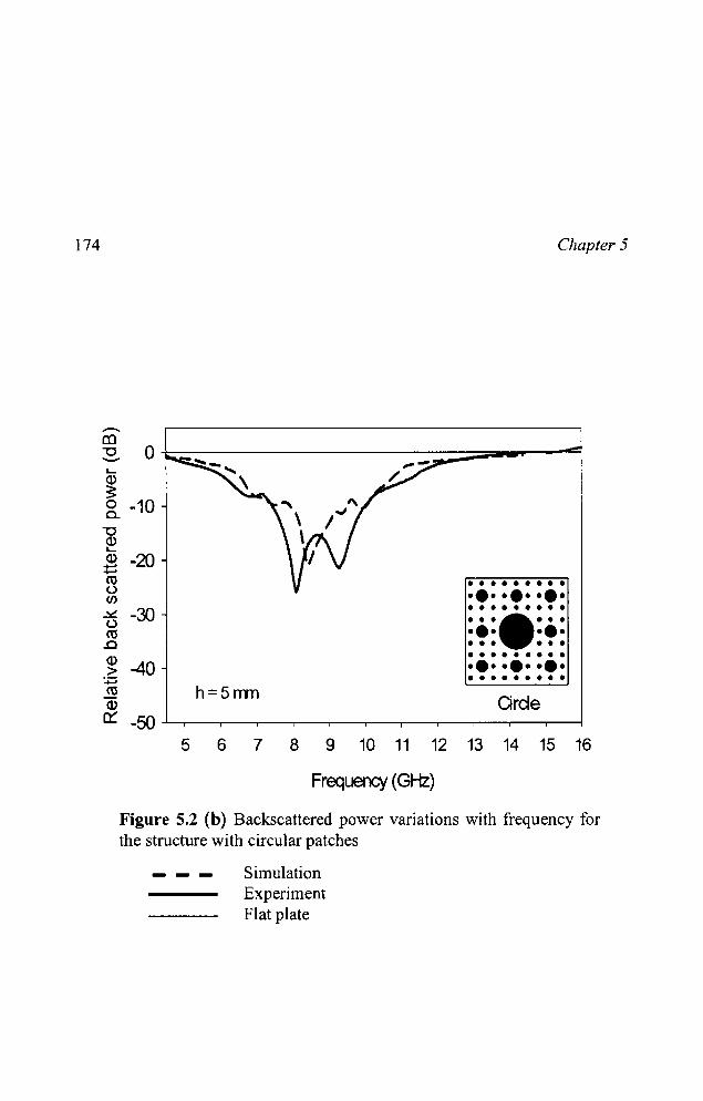
174 Chapter 5
--III
~ O~~-----------------===~~----~ L..
~ o -10 c..
"'C
~ 2 -20 ...... ro u (/J
..::.::. -30 u ro
.Cl
~ -40 :;::; ro Q)
h=5rrm
• • • • • • • • • ·e· ·e· ·e· • • • • • • • • • ••••••• ·e· ·e· • • • • • • • • • • • • • • • ·e· ·e· ·e· a • • • • • • • •
Qrde ~ -so ...L..-r------.---.--------;-----,---r------.---;-------;---,---.-------i
5 6 7 8 9 10 11 12 13 14 15 16
Frequency (GHz)
Figure 5.2 (b) Backscattered power variations with frequency for the structure with circular patches
Simulation Experiment Flat plate
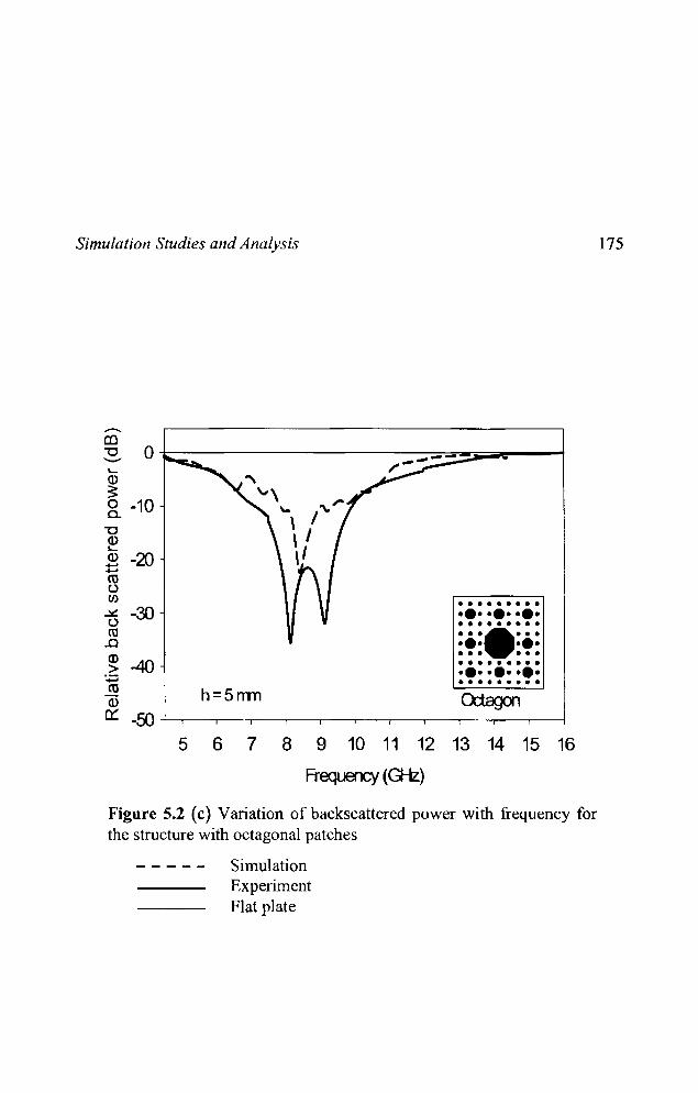
Simulation Studies and Analysis
h=5mn
• •••••••• ••• ••• ••• • •••••••• •••••• • ••• • •• • • • • •• • •••••••• ••• ••• ••• • •••••• ••
5 6 7 8 9 10 11 12 13 14 15 16
Frequercy (G-Iz)
Figure 5.2 (c) Variation of back scattered power with frequency for the structure with octagonal patches
Simulation Experiment Flat plate
175
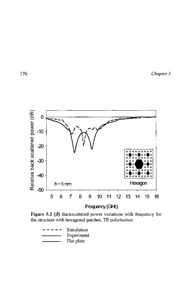
176 Chapter 5
h=5mn
• • • • • • • • • .•. ·e· ·e· • • • • • • • • • ••••••• ·e· ·e· • • • • •• • • • • • • • • • .•..•. ·e· a • • • • • • • •
Hexagon
5 6 7 8 9 10 11 12 13 14 15 16
Frequency (GHz)
Figure 5.2 (cl) Backscattered power variations with frequency for the structure with hexagonal patches, TE polarisation
- - - - - Simulation Experiment Flat plate

Simulation Studies and Analysis
--~ 0 ~~------------------------------------------~ -..... ID
~ -10 a.
"'C ID ..... ID -20 ...... ...... ro u (/)
.::t: -30 u ro ..c ID > -40 :;::::; ro ID
0:::
• • • • • • • • • ••••••••• • • • • • • • • • ••••••• ••• • •• • • • • •• • • • • • • • • • ••••••••• • • • • • • • • • Cross h=5mm
-50 ...L-,--.------r----r-----,----.----.---,---,---.------r----j
5 6 7 8 9 10 11 12 13 14 15 16
Frequency (GHz)
177
Figure 5.2 (e) Backscattered power variations with frequency for the structure with generator of the shape of cross
Simulation Experiment Flat plate
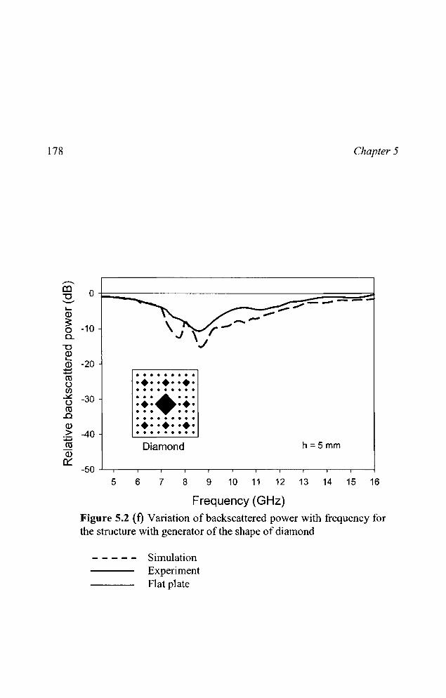
178
-CO "'0 ----L-Q)
~ 0 c..
"'0 Q) L-Q) ..... ..... cu c..> Cl) ~
c..> CtI ..c Q) >
;,0:; CtI Q)
0:::
Chapter 5
0
-10
-20 • • • • • • • • • ••••••••• · . . . . . . . .
-30 ••••••• ••• • •• • • • • •• · . . . . . . . . ••••••••• -40 · ...... . . Diamond h=5mm
5 6 7 8 9 10 11 12 13 14 15 16
Frequency (GHz) Figure 5.2 (f) Variation of backscattered power with frequency for the structure with generator of the shape of diamond
- - - - - Simulation Experiment Flat plate

Simulation Studies and Analysis
..-ca "'0 ---I-ID ;: 0 c.
"'0 ~ ID ....... ....... ro u (/) ~ <..> ro ..c (l) > :..::; ro ID
et:
0
-10
-20
• •••••••• ••••••••• -30 • ••••••••
• •••••••• ••• ••• ••• • •••••••• • •••••••• ••••••••• -40 • •••••••• Carpet array h:::5mm
-50 ..L-.--------,-----.----,----.---,---.------,------,---,--.-------1
567 8 9 10 11 12 13 14 15 16
Frequency (GHz)
Figure 5.2 (g) Variation of backscattered power against frequency for the structure with array of second iterated stage of Sierpinski carpet
Simulation Experiment Flat plate
179
From the observations it can be concluded that the reduction in
backscattered power depends on the area occupied by the patch. The
backscattered power obtained is high for Sierpinski carpet fractal structure
with diamond, cross bar fractal tree, Purina square and star as generators.
1bis is due to the fact that the patch area occupied by this geometry is less
compared to other geometries such as Square, octagon, hexagon, circle,
array of Sierpinski carpet. It is also noted that the central patch plays an
important role in the reduction of backscattered power.
180 Chapter 5
5.3 RCS ENHANCEMENT OF DIHEDRAL CORNER REFLECTOR
Backscattering property of dihedral corner reflector greatly depends
on the corner angle. For a plane right angled dihedral corner reflector, the
RC) is large. In chapter 4 it is shown that embedding metallo-dielectric
fractal structures reduces the backscattering which means a reduction in
RC). Also low RC) of corner reflectors with acute and obtuse corner
angles can be increased by applying metallo-dielectric structures. Studies
were conducted on dihedral corner reflectors with corner angles in the
range of 650 -1750 for both TE and TM polarizations to verify the
dependence of corner angle on RC) reduction! enhancement.
Figure 5.3 presents the variation of RC) against frequency with and
without loading :MDS, for a dihedral corner reflector with 800 corner angle.
Compared to an unloaded corner reflector, a large value of RC) (above 20
dBsm) is obtained in the frequency range 9.15 - 10.33 GHz for substrate
thickness of h = 3 mm, the peak (31 dBsm) being at 9.55 GHz. The
backscattered cross section as a function of angle of incidence at this
frequency is shown in Fig. 5.4.
Large enhancement in RC) is obtained for a corner angle of 1200
also. The plot of RC) against frequency with and without loading :MDS for
1200 corner angle is shown in figure 5.5. A maximum RC) is obtained for
9.4 GHz for a dielectric thickness h = 2mm. RC) variations with angle for
this configuration is shown in figure 5.6. RC) variations with corner angles
at f = 9.55 GHz and 9.4 GHz for TM and TE polarizations are shown in
figures 5.7 and 5.8 respectively.

Simulation Studies and Analysis
40,-------------------------,
30
......... 20 E (J)
al '0 10 (j) l)
~ 0
-10
-20+-------~---~-----~------~
8 9 10 11 12 Frequency (GHz)
Figure 5.3 Variation ofRCS against frequency for normal incidence (h = 3 mm)
181
--MDS loaded, TM polarization ---- MDS loaded, TE Polarization .......... 80° plain dihedral corner reflector
40,--------------------------~
30
......... 20 E (J)
al :s. 10 Cl) l) 0::: 0
-10
-20 -60 -40 -20 0 20 40 60
Angle of incidence (deg)
Figure 5.4 Variation ofRCS against angle of incidence, h = 3 mm -- MDS loaded, TM polarization - - - - MDS loaded, TE polarization .......... 80° plain dihedral corner reflector

182
40~----------------------------------~
30
.-20 E Cl)
~ 10 --Cl)
U 0:: 0
-10
:.--, ~ \
\ I ................. " ......•.•......... \ \ \
-20+---------._-------,---------.--------4 8 9 10 11 12
Frequency (GHz)
Chapter 5
Figure 5.5 Variation ofRCS against frequency for nonnal incidence h=2mm ---- MDS loaded, TM polarization - - - - MDS loaded, TE polarization
1200 plain dihedral corner reflector 40.------------------------------------,
30
-20 E Cl)
CO ~10 Cl)
U 0:: 0
-10 · · · · , , . . ..
','
\ '
\ :.\/ , , , , . . , . , , '.'
-20~._--~----~----_r----~----~----~
-60 -40 -20 0 20 40 60
Angle of incidence (deg)
Figure 5.6 Variation of RCS against angle of incidence, h = 2 mm --- MDS loaded, TM polarization - - - - MDS loaded, TE polarization ... .... ... 1200 plain dihedral corner reflector
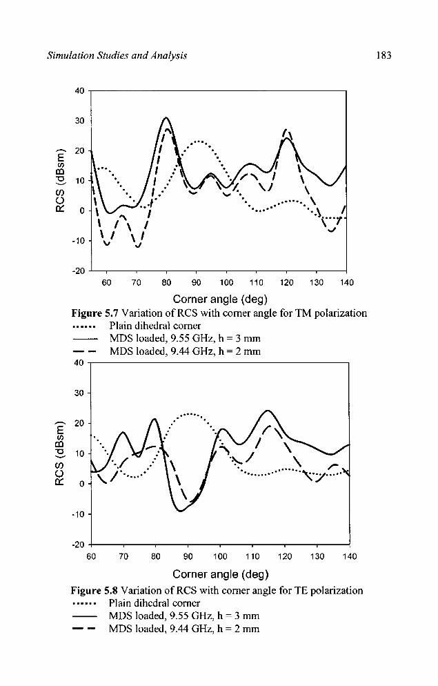
Simulation Studies and Analysis
,-....
E Cl)
CD "0 -(f) () 0::
-.. E Cl)
CO "0 -(f) () 0::
40
30
... . . . 20 . . . . . . 10 - . ... . ........ \ ..... - ... \ I , ... ., , , ~
-10 ..J
-20 60 70 80 90 100 110 120 130 140
Corner angle (deg) Figure 5.7 Variation ofRCS with corner angle for TM polarization
Plain dihedral corner
40
30
20
10
0
-10
-20 60
MDS loaded, 9.55 GHz, h = 3 mm MDS loaded, 9.44 GHz, h = 2 mm
.- .... . ..
70 80 90 100 110
Corner angle (deg)
120 130 140
Figure 5.8 Variation ofRCS with corner angle for TE polarization Plain dihedral corner MDS loaded, 9.55 GHz, h = 3 mm MDS loaded, 9.44 GHz, h = 2 mm
183

184
.--.. E Cl)
I1l "0 '-"
Cl) 0 c:::
40
30
20
10
0
-10
-20
60
..........
Chapter 5
'" ....................
80 100 120 140
Corner angle (deg)
Figure 5.9 ReS variations with corner angles for TE polarization Plain dihedral corner
-- MDS loaded, 10.03 GHz, h = 3 mm
In chapter 4, it is observed that a large enhancement in RC; in the
case of YE polarization is obtained by loading MDS over a corner reflector
with corner angle a = 105°. The variation of RCS with corner angles at f =
10.03 GHz and h = 3 mm is sho'WI1 in figure 5.9. The results of the
investigation indicate that the RC; of dihedral corner reflector can be
enhanced by loading MDS based on Sierpinski carpet fractal geometries
for both 1E and TM polarization.
Table 2 shows the frequency of minimum RC; and the frequency
of maximum RC; enhancement for dihedral corner reflectors of various
corner angles. The results obtained for both YE and TM polarizations are
listed. Maximum reduction of backscanered power of 45 dB is obtained

Simulation Studies and Analysis 185
for a corner angle a = 1600 in the case of lE polarizations and 47 dB for
corner angle a = 1750 for 1M polarization. Maxinl1Ull enhancement is
observed for corner angle a = 1050 in the case of lE polarization and
a = 1200 in the case of 1M polarization.
Table 2 Frequencies of RCS reduction! enhancement for various corner angles for TE and TM polarizations
Q)mer Frequency of Maximum Frequency of Maximum angle RCS Reduction Res Enhancement
(a) TE TM TE TM (GHz) dB (GHz) dB (GHz) dB (GHz) dB
60 9.9 -31.6 12.6 -43.3 8.47 4.0 4.5 6.7 65 12.43 -22.1 15.15 -45.3 16 9.9 8.55 3.4 70 12.75 -37.5 728 -36 15.8 14.4 10.68 14.2 75 10.15 -37.7 8.83 -26.7 8.65 6.8 7 15.6 80 12.38 -23.4 12.93 -33.4 10.7 12.4 9.55 22 85 11.55 -31.6 13.95 -29.6 5.15 8.9 5.78 18.2 90 9.05 -32.8 8.03 -40 - - 6.3 0.9 95 7.24 -31.7 6.19 -30.8 8.85 0.8 9.55 4.0 100 9.08 -18 6.53 -21.6 15 9.3 10 16.3 105 9.3 -24.3 9.75 -25 10.03 19.1 9.98 13.7 110 10.28 -10.5 15.15 -23.7 10.5 10.9 9.53 9.6 115 8.95 -26.1 14.55 -35.6 10.28 14 4.5 17.5 120 10.9 -18.8 6.9 -26.8 10.03 11.7 9.4 22.9 125 10.65 -29.1 11.7 -14.2 9.85 15.8 10.9 20.7 130 9.53 -33 14.83 -15.9 14 7.2 10.35 17.8 135 9.85 -32 10.08 -28.2 9.03 5.4 11.78 17.2 140 12.88 -36.5 4.72 -26.9 11.25 4.1 9.25 14.1 145 11.43 -20'.1 11.77 -24.5 11.05 6.8 9.13 18.9 150 12.36 -28.5 15.9 -22.6 7.87 9.9 8.8 9.4 155 7.23 -35.2 8.08 -13.3 8.9 6.4 9.33 20.9 160 6.3 -45 5.9 -20.5 10.58 8.1 10.53 18.4 165 8.4 -21.2 7.39 -36.4 10.48 3.8 10.7 13.5 170 5.85 -38.2 7.5 -33.7 - - - -175 9.15 -22 5.85 -46.6 - - - -

186 Chapter 5
5.4 EFFECT OF SUPERSTRATE LOADING
A structure is optimised to get a minimum RCS at a particular
frequency by adjusting the substrate thickness. Experiments have proved
that the frequency can be tuned by applying superstrates of different
thickness. The frequency of tuning effect of the structures based on
Sierpinski carpet and Sierpinski gasket are shown in tables 3 and 4
res pectively.
Table 3 Effect ofloading superstrates on Sierpinski carpet structure
Substrate thickness Superstrate Frequency of minimum
h(mm) thickness, t (mm) backscattering , f (GHz)
0 13.7
3 0.6 U.03
1 11.24
1.5 10.7
Table 4 Effect of loading superstrates on Sierpinski gasket structure
Subs tra te thickness Superstrate Frequency of minimum
h(mm) thic~ess, t(mm) backscattering, f (GHz)
0 8.9
1 8.29
5 2 7.74
3 7.26
4 6.94
5 6.74

Simulation Studies and Analysis 187
5.5 EFFECT OF DIELECTRIC CONSTANT
The effect of dielectric constant on the frequency giving minimum
backscattering is studied for a particular structure. Table 5 shows the
simulated results for different dielectric constant with a substrate thickness
of 5 mm.
Table 5 Effect of dielectric thickness on the resonance frequency
Freqencyof Dielectric IIl1numum constant backscattering
(GHz) 2.2 8.6
2.56 8.4
4.4 8.0
10.2 5.0

Chapter 6
CONCLUSIONS
This chapter presents the conclusions drawn from the investigations
carried out in lowering the ReS of targets. Studies conducted by
embeddingfractal based metal/a-dielectric structures on targets such as
metallic flat plate, cylinder, dihedral corner reflector and circular cone
conducted for both TE and TM polarizations are found to be very
effective in reducing the ReS of targets over a wide frequency band.
Scope for further work related to this field is also discussed.

Conclusions 191
6.1 INFERENCES FROM EXPERIMENTAL INVESTIGATIONS
6.1.1. Fractal Based Metallo-Dielectric Structures Loaded Flat Plate
The results of the backscattering characteristics for various iterated
stages of Sierpinski catpet fractal based metallo-dielectric structures loaded
flat plates were presented in section 4.1.1. It is observed the third iterated
stage is giving a maxllnwn reduction in backscattered power when
measured for nonnal incidence. Also there is an optimum thickness for the
dielectric substrate giving maximum backscattering reduction in a
particular band. A reduction of backscattered power of 28.6 dB (h=3 mm),
32 dB (h=4 mm) and 28.8 dB (h = 3 mm) in C, X and Ku bands
respectively is obtained compared to a flat plate of same physical
dimension. The backscattered power measurement with angle of incidence
shows that the reduction is obtained for other incident angles also, with
large backscattering at the blazing angles. The reduction is obtained for
due to the power scattered in different directions and the measurements
indicated that the scattered power is distributed synunetrically with respect
to nonnal in both azimuthal and elevation angular ranges. This is true for
both TE and 1M polarizations, due to the synunetry in the nature of the
geometry.
Scattering results of Sierpinski carpet with generators of different
shapes are described in section 4.1.2. Patches of different shapes are
applied to the third iterated stage of the Sierpinski catpet, as this
configuration is giving minimwn backscattering. From the observations it
is found that Sierpinski carpet with hexagonal patches is giving maximwn
192 Chapter 6
reduction m backscattered power of 45 dB at f = 13.04 GHz. The
optimum substrate thickness giving maximum reduction in backscattered
power is h = 10 mm. It is also observed that the backscattered power
obtained is high for Sierpinski carpet fractal structures with patches of the
shape of cross bar fractal tree. This is due to the fact that the patch area
occupied by this geometry is less compared to other geometries. It is
inferred that the backscattering depends on the area occupied by the
patches.
Backscattering reduction to an appreciable range of frequencies is
obtained for the Sierpinski carpet structure with square patches. A
bandwidth (below -10 dB) of 2.83 GHz is obtained for a substrate
thickness h = 5 mm compared to other structures.
From the observations it is seen that the backscattering
characteristic for TE and 1M polarizations are different for Sierpinski
carpet structures with patches of the shape Star and Hexagon. This is due
to non synunetry in its shape.
Loading superstrates on Sierpinski carpet fractal geometry and
Sierpinski gasket fractal geometries are found to be effective in shifting the
frequency of minimum backscattering to the desired frequency.
Superstrates loading over Sierpinski carpet structure in a shift in the
frequency of minimum backscattering from Ku to X band, as the
superstrate thickness is increased. A reduction of -28 dB at 13.7 GHz is
shifted to 10.7 GHz giving -27 dB by increasing the superstrate thickness
by 1.5 mm, while Sietpinski gasket structure shifts the frequency of
Conclusions 193
minimum backscattering from X to C band. Here a reduction of -31 dB at
8.9 GHz is shifted to 6.76 GHz giving - 21 dB by increasing the
superstrate thickness by 5 mm.
The results of the scattering behaviour of Sietpinski carpet fractal
geometries with same fractal dimension and varying lacunarity is presented
in chapter 4.3. Reduction in backscattered power in all the three frequency
bands (c, X and Ku) is obtained for the structure with medium lacunarity.
6.1.2. Experiments with3D structures
(a) Metallic Cylinder
Scattering studies conducted on metallic cylinder by loading
Sietpinski carpet based metallo-dielectric structure is presented in section
4.4. It is observed that loading fractal based structures is effective in
reducing the backscattered power for both TE and 1M polarizations of the
incident field.
Maximum reduction of - 35 dB in backscattering for TE polarization
15 obtained at f = 10.18 GHz, for a substrate thickness h = 4 mm
compared to a metallic cylinder of same physical dimensions. Maximum
backscattered power is obtained for an angle of incidence of 15°.
In the case of Th1 polarization, a maximum reduction of -35 dB is
obtained at f = 9.78 GHz for a substrate thickness h = 4 mm. In this case,
maximum backscattered power is obtained for an angle of incidence of 7°.
Similar results are obtained for the horiwntallyoriented cylinder also.

194 Chapter 6
(b) Dihedral Corner Reflector
Studies on the scattering characteristics of dihedral corner reflector
loaded with fmctal structures have given some interesting results. Here
Res reduction is obtained for a 900 corner reflector while the Res is
enhanced for acute and obtuse corner angles.
Experiments conducted using a corner reflector with adjustable
corner angle yielded the following results. In the case of 1E polarization, a
maximum reduction in backscattered power of 33 dB at f = 9.05 GHz is
obtained for h = 4 nun for 900 corner reflector when compared to metallic
dihedral corner reflector of same physical dimension. For 1M polarization,
reduction is 40 dB at f = 8.03 GHz for the same thickness h = 4 mm.
For acute and obtuse angles, the backscattered power is more than
that of a plane corner reflector. So, this technique is suitable for enhancing
the Res of dihedral corner reflectors. An Res enhancement of -30 dBsm
is obselVed for corner reflector with angle a = 80° and 1200 corner angle.
(c) Cin:ular Cone
Backscattering studies of metallic circular cone loaded with Sierpinski
carpet based metallo-dielectric structure is presented in section 4.6. It is
observed that this technique reduces the backscattering from the cone for
both 1E and 1M polarizations of the incident field.
Conclusions 195
A maximum reduction ID backscattered power of 25.5 dB with
respect to metallic cone, at f = 8.1275 GHz is obtained for a dielectric
thickness of h = 1.2 mm. Maximum backscattered power of -10.92 dB is
obtained for an angle of incidence of 50. The results obtained are identical
for both 1E and 1M polarizations.
6.2 CONCLUSIONS FROM SIMULATION STUDIES AND ANALYSIS
From the experimental results, it is observed that backscattering
reduction over a wide range of frequencies is obtained by loading
Sierpinski carpet based fractal structure on a metallic plate. Embedding this
structure on a dihedral corner reflector gives RCS enhancement at certain
acute and obtuse corner angles.
Simulations studies were conducted for Sierpinski carpets with
different iterated stages and also for Sierpinski carpets with generators of
different shapes. It is concluded that the experimental results are in good
agreement with the simulations results.
It is also observed that the frequency of minimum backscattering
can be tuned by loading superstrate of different thickness over the metaIlo
dielectric structure.
6.3 SCOPE FOR FURTHER WORK IN THIS FIELD
Application of fractal based metallo-dielectric structures in real time
targets like models of aircrafts, ships, vehicles and missiles for reducing the
RCS is an important work to be carried up in this area. This requires more
196 Chapter 6
careful analysis and attention. More detailed investigation could be carried
out in this direction.
Backscattering reduction of flat plates, cylinder, dihedral corner
reflectors and circular cone are carried out in the present work Scattering
studies could be extended to more targets like trihedral corner reflectors,
ellipsoids and bruderhedral.
The study on the scattering characteristics of the metallo- dielectric
structures with temperature, the scattering behaviour of non deterministic
fractal shapes and other deterministic shapes other than Sierpinski carpet
and Sierpinski gasket can be taken up as a further study.
Development of techniques for reducing the backscattering for a
wide angular and wide frequency range requires further detailed
investigation. A suitable theoretical model to different fractal loaded
targets leaves much scope for future work in the field.
Appendix I
DESIGN OF ABANDPASS FILTER USING CANTOR BAR BASED METALL()'DIELECfruC
STRUCfURE
Development of a filter in rectangular waveguides using metallo
dielectric inserts based on Cantor bar fractal geometry is reported. The
structure consisting of an array of cantor bars placed inside introduces
a higher cutoff frequency for the waveguides which results in a
band pass response. The cutoff frequency depends on the parameters of
the array.

199
INTRODUCTION
Wave guide filters usually require a complex and expensive process
of manufacture; but they are very useful in applications where high power
handling is desired. Various techniques are reported in the literature for the
design of waveguide filters. :Many of these designs are based on the use of
short circuited stubs about half a wavelength long as discussed by Matthaei
et al. [1]. Fin lines are also extensively used for constructing microwave
filters [2, 3]. Left handed coplanar wave guide bandpass filters based on
split ring resonators and microstrip bandpass filters are discussed in [4, 5].
A technique for constructing a bandstop wave guide filter containing
multiple-coupled cavities has been proposed in [6]. Seager et. al. A
bandpass type response in a wave guide using a two sided array of close
coupled resonant aperture FSS is presented in [7]. A wave guide filter
employing several conducting cylindrical posts that have a bow-tie shape is
synthesized and investigated in [8]. In this paper we discuss the use of
Cantor bar based fractal structure for designing a wave guide filter.
:Mandelbrot described a family of complex objects or shapes as 'fractal'
[9]. Fractals are structures that posses inherent characteristics such as self
similarity and space filling property. 'The application of fractal geometries
in electromagnetics in radiating, propagation and scattering problems has
gained much interest recently [10 - 12]. In the present work, dielectric
sheet with metallization pattern in the form of an array of cantor bars is
inserted in the wave guide. 'The transmission characteristic is studied by
varying different parameters of the cantor bar geometry.
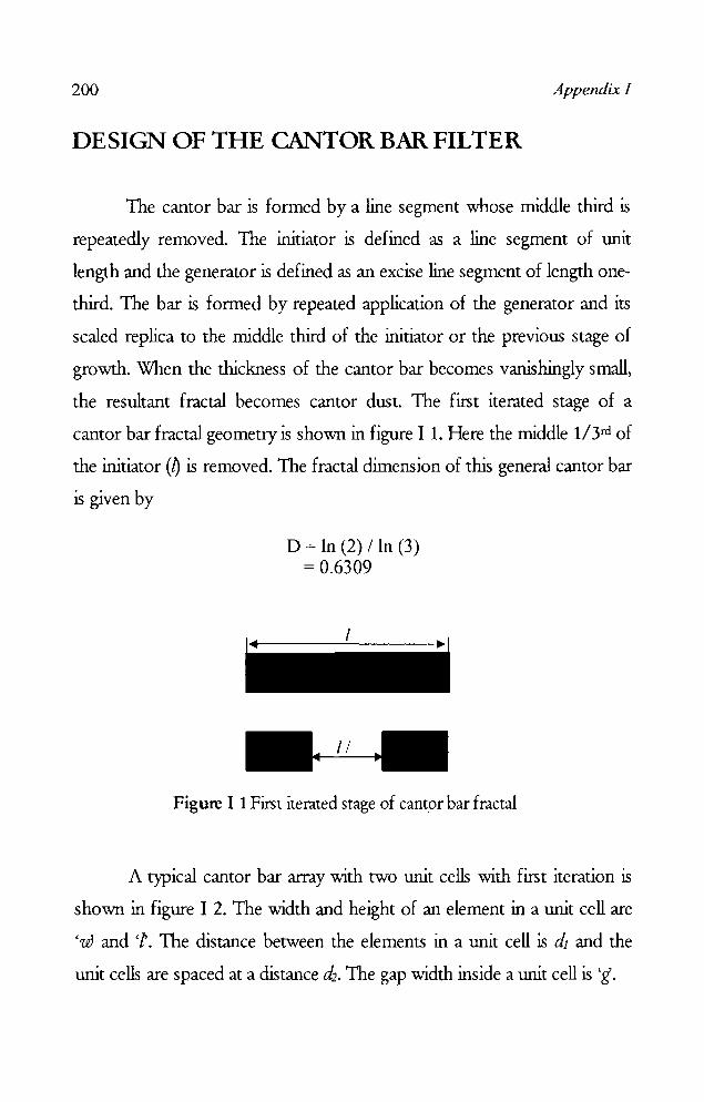
200 Appendix I
DESIGN OF THE CANTOR BAR FILTER
The cantor bar is formed by a line segment whose middle third is
repeatedly removed. The initiator is defined as a line segment of unit
length and the generator is defined as an excise line segment of length one~
third. The bar is formed by repeated application of the generator and its
scaled replica to the middle third of the initiator or the previous stage of
growth. "When the thickness of the cantor bar becomes vanishingly small,
the resultant fractal becomes cantor dust. The first iterated stage of a
cantor bar fractal geometry is shown in figure I 1. Here the middle 1I3rd of
the initiator W is removed. The fractal dimension of this general cantor bar
is given by
D = In (2) /In (3) = 0.6309
Figure I 1 First iterated stage of cantor bar fractal
A typical cantor bar array with two unit cells with first iteration is
sho"WIl in figure I 2. The width and height of an element in a unit cell are
'wand'/'. The distance between the elements in a unit cell is d1 and the
unit cells are spaced at a distance d2• The gap width inside a unit cell is 'g.

1 9
T ~~
w
--~~~~---~ 1
Figure I 2 Cantor bar array of two unit cells
201
The metallo-dielectric structure based on cantor bar array of
foruteen unit cells is photo etched on a FR4 substrate having a thickness t
=1.6 mm and dielectric constant, C r = 4.4. Cantor arrays of unit cells with
I = 7 mm, W = 2 mm, d1 = 2 mm, d2 = 2 mm with different gap width ~
0.05 mm, 1 mm, 1.5 mm and 2.3 mm are fabricated and studied. The
structure is inserted in a X band wave guide as shown in figure 13.
Figure I 3 X - band wave guide with Cantor bar based metallo-dielectric insert
The measurements are perfonned using Rohde and Schwarz ZVB
20 vector network analyzer. The transmission characteristics are studied by

202 Appendix J
inserting the structure in the waveguide at different positions (x) along the
X-axis_ The measurements are also conducted by varying the spacing of
the array elements, spacing of the elements in the unit cell and the number
of unit cells. Ansoft HFSS VID simulation software is used to validate the
experimental results.
RESUfLS AND DISCUSSIONS
The transmission characteristics of the waveguide with cantor bar array
unit cells inserted at different position along the width of the waveguide is
ploned in figure I 4. It is observed that the response is maximum at the
centre of the waveguide.
-ID -0
o ~--~~~~~~~/~_~ .. ~.~ r / I 1\ 1\ !\ .
-20
-40
\ .. v" ... -, , I .
\, I I I
. I
--80 ~
N (/)
-80. - - _. x=2mm ---- x:4mm
;.:=7mm -100 --- x:: 10mm
Waveguide response
-120 +--_--_-_--~-~--~-~ 5 6 7 8 9 10 11 12
Frequency (GHz)
Figure I 4 Transmission characteristic of a waveguide loaded with arrays of cantor bar at different positions (g - 0.5 rnrn. dl - 2 mm. d2 - 2 mm. w - 2 rrun, 1 - 7 rrun,N - 14)

203
Simulated results of the response of the TEIO mode wave guide with
different number of unit cells (N) of the cantor bar, kept at the field
maximum is shown in figure I 5. It is observed that as the number of unit
cell is increased, a bandpass filter response is achieved.
-CD '0 -~
'" Cl)
0 I
(J1/X '~ . , \l . ..... ..... . ,
·20 1, ft: ' ~" . ' ..... \ ".
, , '01 h '·· i{.(: .. .
-40 ,': r"
1\'- \ .... J: I I \ \ .
1\ ·· \ lE I .. 0 ' , i \ \ \ , ,
i \ \ \ , , N=1 I \ \ \ ------
·80 ............. N =3 I \ \ - --- N = 5 I
\ \ - " - '" - ' " N =7 I
..
-100 --- N"9 \ \ N = 14 --_.- N '" 18 \ \
-120 \
5 6 7 8 9 10 11 12
Frequency (GHz) Figure I 5 Transmission characteristic of a v.raveguide loaded with different nwnber cantor bar unit cells 'N (cl, - 2 mm, d2 - 2 mm, w - 2 mm, I - 7 nun)
The effect of gap width on the transmission characteristic of the
waveguide is studied and the measured results are shown in figure I 6. It is
observed that as the gap width is decreased the width of the pass band is
increased. It is also found that the insertion loss is minimum when the gap
width is 0.5 IIU1l.
Figure I 7 shows the transmission characteristics of the wave guide
loaded with arra)' of cantor bar with different period's d, and d,. It is
found that the bandwidth is decreased as the period d, or d, is increased. It
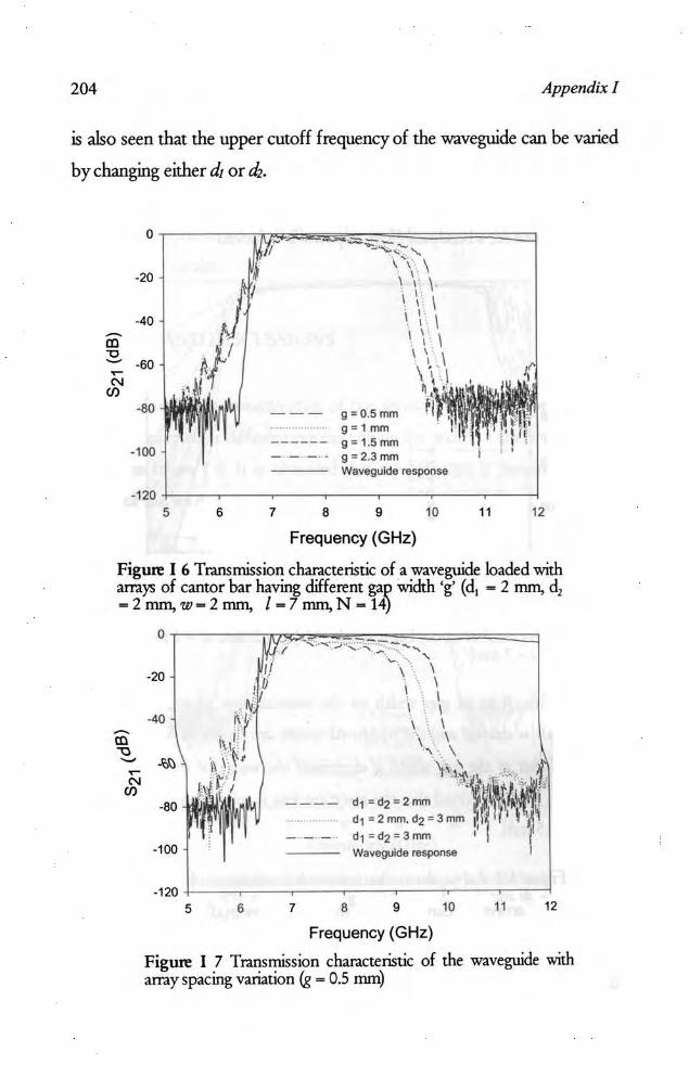
204 Appendix I
is also seen that the upper cutoff frequency of the waveguide can be varied
by cbanging either d, or d,.
0
·20
·40
III "0 - ·60 ~
'" C{)
·80
· 100
-120 S 6 7 8
\ \ \ . \ \ \ \ ,. \
\
g = O.5mm g:1mm g = 1.Smm g=2.3mm Waveguide response
9 10
Frequency (GHz)
11 12
Figure I 6 Transmission characteristic of a waveguide loaded with am.}'i of cantor bar having different gap width 'g' (cl, - 2 rrun, cl, - 2 rrun, w- 2 rrun, 1 - 7 rrun, N - 14)
-III .., -~ '" (J)
0
-20
-40
-11>
-80
-100
-120 5 6
' ... " "'" -.... "
I, \ ! \ i \
---- d1 = d2 "' 2mm d,=2mm. d2 = 3mm
- - - d, ; d2 = 3mm Waveguide response
7 8 9 10
Frequency (GHz)
11 12
Figure I 7 Transmission characteristic of the wave guide with am.y spacing variation (g - 05 mm)

205
Figure I 8 shows the results in a Gband waveguide. Here also the
Cantor bar array introduces a higher cutoff frequency in the wave guide
which can be controlled by varying the parameters of the array.
0 .. ~
I \. ---I '\ "-
-10 \ 1 \
1 \ \ -20
\ \ I
1 CD ·30 I
1 "0 I .....
1 C\I I (J) -40 1 1 ('
-50 I 1 --- {= 11 mm I1
-60 \ _.- _ .. - {= 19 mm I1 1 Waveguide response
-70 3 4 5 6 7 8
Frequency (GHz)
Figure I 8 Transmission characteristic of a Gband wave guide loaded with array of cantor bar (g = 0.5 mm, d! = 2 mm, d2 = 4 mm, w = 2 mm, x = 10mm,N = 14)
From the observations it can be concluded that the upper cutoff
frequency of the waveguide can be controlled by varying either of the
parameters I, g, d1 or d2. So that a bandpass response is obtained in the
wave guide.
CONCLUSION
Metallo-dielectric structure based on arrays of cantor bar fractal
geometry is useful in bringing in an upper cutoff frequency in a waveguide.
The higher cutoff frequency depends on the gap width, height of the unit
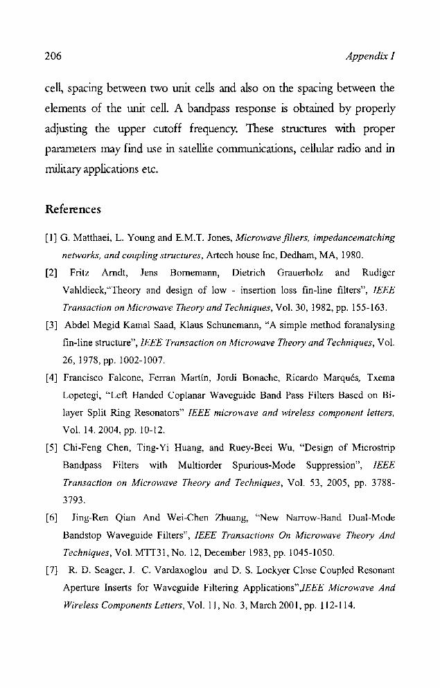
206 Appendix J
cell, spacing between two unit cells and also on the spacing between the
elements of the unit cell. A bandpass response is obtained by properly
adjusting the upper cutoff frequency. These structures with proper
parameters may find use in satellite communications, cellular radio and in
military applications etc.
References
[I] G. Matthaei, L. Young and E.M.T. lones, Microwavefilters, impedancematching
networks, and coupling structures, Artech house Inc, Dedham, MA, 1980.
[2] Fritz Amdt, lens Bomemann, Dietrich Grauerholz and Rudiger
Vahldieck,"Theory and desib'll of low - insertion loss fin-line filters", IEEE
Transaction on Microwave Theory and Techniques, Vol. 30, 1982, pp. 155-163.
[3] Abdel Megid Kamal Saad, Klaus Schunemann, "A simple method foranalysing
fin-line structure", IEEE Transaction on Microwave Theory and Techniques, Vol.
26,1978, pp. 1002-1007.
[4] Francisco Falcone, Ferran Martin, lordi Bonache, Ricardo Marques, Txema
Lopetegi, "Left Handed Coplanar Waveguide Band Pass Filters Based on Bi
layer Split Ring Resonators" IEEE microwave and wireless component letters,
Vol. 14.2004, pp. 10-12.
[5] Chi-Feng Chen, Ting-Yi Huang, and Ruey-Beei Wu, "Design of Microstrip
Bandpass Filters with Multiorder Spurious-Mode Suppression", IEEE
Transaction on Microwave Theory and Techniques, Vol. 53, 2005, pp. 3788-
3793.
[6] ling-Ren Qian And Wei-Chen Zhuang, "New Narrow-Band Dual-Mode
Bandstop Waveguide Filters", IEEE Transactions On Microwave Theory And
Techniques, Vol. MTT31 , No. 12, December 1983, pp. 1045-1050.
[7] R. D. Seager, 1. C. Vardaxoglou and D. S. Lockyer Close Coupled Resonant
Aperture Inserts for Waveguide Filtering Applications",IEEE Microwave And
Wireless Components Letters, Vot. 11, No. 3, March 2001, pp. 112-114.
207
[8] R. Lech and J. Mazur, "Tunable waveguide filter with bow-tie metallicposts",
lEE Proc.-Microw. Antennas Propag., Vol. 151, No. 2, April 2004, pp. 156-160.
[9] B. B. Mandelbrot, The Fractal Geometry a/nature, New York, W. H. Freeman,
1983.
[10] D. H. Wemer and S. Ganguly, "An overview of fractal antenna engineering
research", IEEE Antennas and propagation Magazine, 2003, pp. 38-57.
[11] J. Romeu and Y. Rahmat-Samii, "Fractal FSS: A novel dual-band frequency
selective surfaces", IEEE Transaction on Antennas and propagation, Vol.40,
2000, pp. 1097 - 1105.
[12] A. R. Chandran, T. Mathew, C. K. Aanandan, P. Mohanan and K. Vasudevan,
"Low Backscattered Dual-Polarised Metal/o-Dielectric Structure Based on
Sierpinski Carpet", Microwave and Optical Technology Letters., Vol. 40. No.3.
February 2004, pp. 246 - 248.

Appendix 11
DEVELOPMENT OF AN RCS MEASUREMENT FACILITY AND ITS AUfOMATION
The development of a setup for measurement of Radar Cross Section of
different types of targets and its automation are presented in this
appendix. Both monostatic and bistatic measurements of RCS can be
done using this facility.
211
MEASUREMENT SETUP AND ITS AUTOMATION
The setup consists of a semicircular wooden frame (Arch) that
allows the transmitting and receiving antennas to be ftxed at a constant
distance from the target, for a variety of subtended angles. The radius of
the arch is ~92 inch cm and its circumference is ~288 inch. The target is
mounted on a stepper motor based turntable placed at the centre of the
arch. The transmitting antenna is mounted on a wooden carriage is placed
just outside the arch which can be moved parallel to the arch. The receiver
antenna support is mounted on a stepper motor assembly unit that can be
moved on the arch. The target rotation as well as the receiving antenna
movement is controlled by two separate stepper motors driven by a
microcontroller based unit, interfaced to a Pc. Rhode & Schwarz network
analyzer ZVB 20 is also interfaced to the Pc. The measurements can be
taken with an accuracy of one degree, using this set up. The photograph
of the measurement setup is shown in Figure 11. 1.
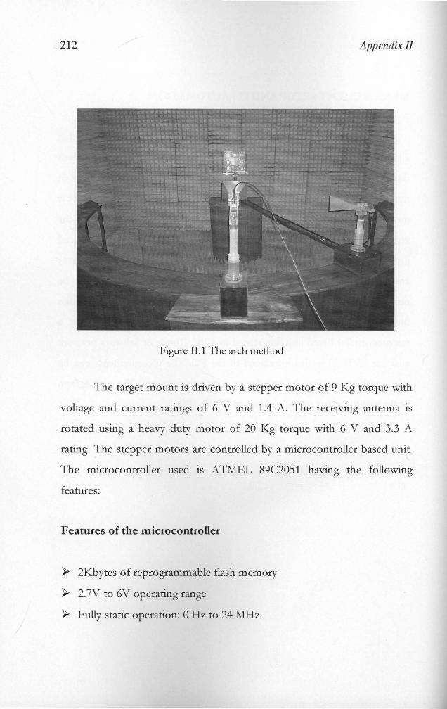
· 212 Appendix Il
Figure II.l The arch method
The target mount is driven by a stepper motor of 9 Kg torque with
voltage and current ratings of 6 V and 1.4 A. The receiving antenna is
rotated using a heavy duty motor of 20 Kg torque with 6 V and 3.3 A
rating. The stepper motors are controlled by a microcontroller based unit.
The microcontroller used is ATMEL 89C2051 having the following
featu res:
Features of the microcontroller
~ 2Kbytes o f reprogrammable flash memory
~ 2.7V to 6V operating range
~ Fully static operation: 0 Hz to 24 MHz
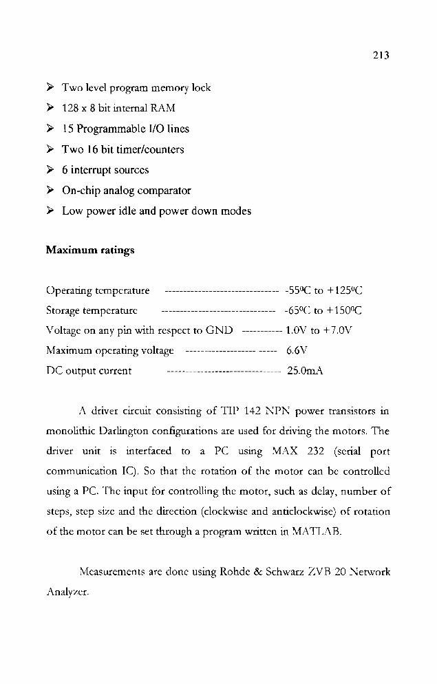
» Two level program memory lock
» 128 x 8 bit internal RAM
» 15 Programmable 110 lines
» Two 16 bit timer/counters
» 6 interrupt sources
» On-chip analog comparator
» Low power idle and power down modes
Maximum ratings
Operating temperature ------------------------------- -550C to + 125°C
Storage temperature ------------------------------- -65°C to + 1500C
Voltage on any pin with respect to GND ----------- 1.0V to + 7.0V
Maximum operating voltage ------------------- ----- 6.6V
DC output current ------------------------------- 25.0mA
213
A driver circuit consisting of TIP 142 NPN power transistors in
monolithic Darlington configurations are used for driving the motors. The
driver unit is interfaced to a PC using MAX 232 (serial port
communication Iq. So that the rotation of the motor can be controlled
using a Pc. The input for controlling the motor, such as delay, number of
steps, step size and the direction (clockwise and anticlockwise) of rotation
of the motor can be set through a program written in ~1ATLAB.
Measurements are done using Rohde & Schwarz 7.VB 20 Network
Analyzer.
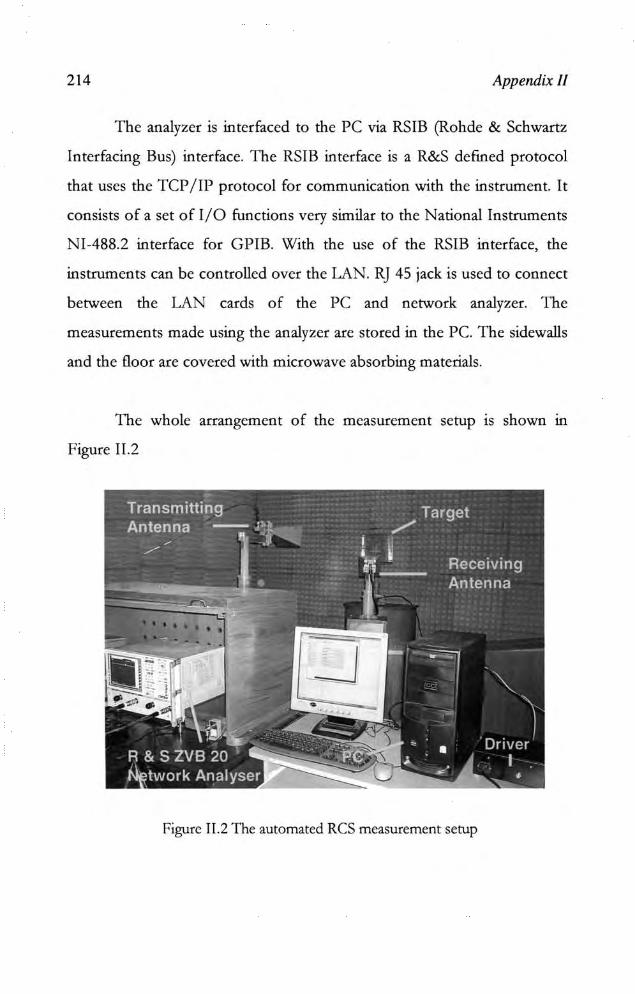
214 Appendix J/
The analyzcr is interfaced to the PC via RSIB (Rohde & Schwartz
Interfacing Bus) interface. The RSIB interface is a R&S defined protocol
that uses the TCP / 11' protocol for communication with the instrument. It
consists of a set of I/O functions very similar to the National Instruments
NI-488.2 interface for GPIB. With the use of the RSIB interface. the
instruments can be controlled over the LAN. RJ 45 jack is used to connect
between the LAN cards of the PC and network analyzer. The
measurements made using the analyzer are stored in the Pc. The sidewalls
and the floor are covered with microwave absorbing materials .
The whole arrangement of the measurement setup 15 shown U1
Figure 11.2
Figure II.2 The automated ReS measurement setup

215
CONCLUSION
An automated setup is developed and used for measurement of
Radar Ooss Section using the Rohde & Schwarz vector network analyzer.
TIlls automated setup can also be used for the measurement of antenna
radiation patterns at multiple frequencies with less time effort.
References
I) Muhammad Ali Mazidi & Janice Gillispie Mazidi, "The 8051 Microcontroller
and embedded systems", Pearson education, Sixth edition, 2003
2) KennethJ.Ayala, "The 8051 Microcontroller", Penram international publishing
Pvt.Ltd, Second edition, 1998
3) Ajay.V.Deshmukh, "Microcontrollers-Theory and Applications", Tata McGraw
Hill, Second edition, 2005
4) Eugene.F.Knot John.F.Shaeffer Michael.T.Tuley "Radar Cross Section Its
Prediction Measurement and Reduction", Artech House, 1985
5) Rohde & Schwarz ZVB20 Vector Network Analyzer Reference Manual

217
REFERENCES
I. George T. Ruck, '"Radar Cross Section handbook" Vol. I & 11,
Plenum Press, New York, 1970.
2. M. I. Skolnik, '"Introduction to Radar systems", Mc Graw Hill, 1989.
3. Eugene F. Knott, John F. Shaeffer, and Micheal T. Tuley, '"Radar
Cross Section" Artech House Inc., Dedham, M. A, 1989
4. Nicholas C. Curie, "Techniques of Radar reflectivity measurements"
Artech House Inc., Dedham, M. A, 1989.
5. Y. Y. Hu, "Backscattering cross section of a center loaded cylindrical
antenna," IRE Trans. Antennas & prop., Vol. AP-36, No. I, pp 140-
148, Jan 1958.
6. W. J. Bow, A. S. King and C. E. Lee, "Scattering from finite array of
microstrip patches on uniaxial substrate", lEE Electron. Lett., Vol.
28, No. 2, pp. 126 - 127. January 1992.
7. E. H. Newman and D. Forria, "Scattering from microstrip patches",
IEEE Trans Antennas Propagat , Vo!. 35, No. 3, pp. 245 -251,
March 1987.
8. D. Pozar, "Radiation and Scattering from a Microstrip Patch on a
Uniaxial Substrate", IEEE Trans Antennas Propagat , Vol. 35, No.
6, pp.613-621,JuneI987.
9. D. R. Jacks on , 'The RCS of a rectangular Microstrip patch in a
substrate-superstrate geometry", IEEE Trans Antennas Prop., Vo!.
38, No. I, pp. 2 - 8, January 1990.

218 References
10. A. Taflove and K. Umashankar, "Radar Cross Section of General
Three - Dimensional Scatterers", IEEE Trans Antennas Prop., Vol.
25, No. 4, pp. 433 - 440, Nov. 1983.
11. D. Colak, A. I. Nosich and A. Altintas, '"Radar Cross Section study
of cylindrical cavity backed Apertures with Outer or Inner Material
Coating: The Case of H-Polarization", IEEE Trans Antennas Prop.,
Vol. 43, No. 5, pp. 440 - 447, May 1995.
12. C. -G. Park, N. -H. Myung and S. -D. Choi, "Efficient solution for
backscattered field of a dihedral corner reflector" lEE Electron.
Left., Vo!. 31, No. 9, pp. 706-707, April 1995.
13. D. A. Edward, R. A. McCulloch and W. T. Shaw, "Variational
estimation of radar cross section", lEE proceedings, Vo!. 137, No. 4,
Aug. 1990.
14. C. W. Harrison and R.O. Heinz "On the radar cross section of rods,
tubes and strips of finite conductivity " IEEE Trans. Antennas &
prop., Vo!. AP-ll, No. 4, pp 459-468, July 1963.
15. Charles M. Knop "On the Radar Cross Section of a coated plate"
IEEE Trans Antennas & prop., "Vol AP-II, No.6, pp 719-721, Nov
1963.
16. W. E. Blore, "The radar cross section of ogives, double backed
cones, double rounded cones and cone spheres", IEEE Trans.
Antennas and prop., Vol AP-12, No. 5, pp 582-590, Sept 1964.
17. John Rheinstein, " Scattering of electromagnetic waves from
dielectric coated conducting spheres", IEEE Trans. Antennas &
prop., Vo!. AP-12, No. 3, pp 334-340, May1964.

219
18. T .B.A. Senior, "A survey of analytical techniques for cross section
estimation", Proc. of IEEE, Vo1.53, pp 822-832, Aug 1965.
19. P. Blacksmith, R.E. Hiatt and R.B. Mack. "Introduction to radar
cross section measurements", Proc. of IEEE, Vol. 53, pp 901-920,
Aug 1965.
20. J. W. Crispin and A. L. Maffet, "Radar cross section estimation of
simple shapes", Proc. of IEEE, Vol.53, pp 833-848, Aug 1965.
21. 1. W. Crispin and A. L. Maffet, "Radar cross section estimation of
complex shapes" Proc. of IEEE, Vol. 53, pp 972-982, Aug 1965.
22. R. G. Kouyoumijian and L. Peters, "Range requirement in the radar
cross section measurements," Proc. of IEEE, Vol. 53, pp 920-928,
Aug 1965.
23. C.C. Freeny, "Target support parameters associated with radar
reflectivity measurements", Proc. of IEEE, Vol. 53, pp 929-936,
Aug 1965.
24. V. V. Liepa and T. B. A. Senior, "Modification of the scattering
behaviour of a sphere by loading", Proc. of IEEE, Vol. 53, pp. 1004-
1011, Aug 1965.
25. H. A. Corriher and Berry O. Pyron, "A bibliography of articles on
radar reflectivity and related subjects 1957-1964", Proc. of IEEE,
Vol. 53, pp 1025-1058, Aug 1965.
26. A.V. Alongi, R.E. Kell and D. J. Newton, "A high resolution X-band
FM/CW radar for RCS measurements", Proc. of IEEE, Vol. 53, pp
1072-1076, Aug 1965.
27. C. R. Millin, R. Sandburg and C. O. Velline, "A numerical technique
for the detennination of scattering cross section of infinite cylinders
220 References
of arbitrary cross section", IEEE Trans. Antennas and prop., Vol
AP-13, No. 5, pp 141-149, Jan 1965.
28. R.A. Ross, "Radar cross section of rectangular flat plate as a
function of aspect angle", IEEE Trans. Antennas prop., Vol. AP-14,
pp. 329-335, May 1966.
29. E.K. Miller, G.J. Burke, B.J. Maxum, G.M. Pjerrou and A.R.
Neureuthev. "Radar cross section of a long wire", IEEE Trans.
Antennas prop., Vol. AP-17, No. 3, pp. 381-383, May 1967.
30. Nicholas C. Alexopoulos, "Radar cross section of perfectly
conducting sphere coated with certain class of radially
inhomogenous dielectrics", IEEE Trans. Antennas prop., Vol. AP-
17, No. 5, pp. 667-669, Sept 1969.
31. E. K. Miller and J.B. Morton, " The RCS of a metal plat with
resonant slot", IEEE Trans. Antennas prop., Vol. AP-18, No. 2, pp.
290-292, March 1970.
32. Jiunn S. Vu, " Radar cross section of a thin plate near grazing
incidence", IEEE Trans. Antennas prop., Vol. AP-22, No. 15, pp.
711-713, Sept.1970.
33. Y. Rahmat-Samii and Raj Mittra, "Integral equation solution and
RCS computation of a thin rectangular plate", IEEE Trans. Antennas
prop., Vol. AP-22, No. 4, pp. 608-610, July 1974.
34. J.L. Lin, W.L. Curtis and M.C. Vincent, "Radar cross section of a
rectangular conducting plate by wire mesh mode1ing" IEEE Trans.
Antennas prop. Vol. AP-22, No.5, pp. 718-720, Sept. 1974.
35. W.B. Weir, L.A. Robinson and Don Parker, "Broadband automated
radar cross section measurements", IEEE Trans. Antennas prop.,
Vol. AP-22, No.6, Nov. 1974.

221
36. Joseph R. Mautz and Roger F. Harrington, "Radiation and
scattering from large polygonal cylinders, Transverse Electric
Fields", IEEE Trans. Antennas prop., Vo!. AP-24, NoA, pp. 469-
477, July 1976.
37. P. Corona, G. Ferrara and C. Gennaralli, "Backscattering by loaded
and unloaded dihedral corners", IEEE Trans. Antennas prop., Vo!.
AP-35, No.lO, pp. 1148-1153, Qct 1987.
38. Timothy Griesser and Constantine A. Balanis, "Dihedral corner
reflector backscatter using higher order reflections and diffractions",
IEEE Trans. Antennas prop., Vol. AP-35, No. 11, ppI235-1247,
Nov. 1987.
39. Ercument Arvas and Tapan K. Sarkar, "RCS of two dimensional
structures consisting of both dielectric and conductors of arbitrary
cross section", IEEE Trans. Antennas prop., Vol. AP-37 , No.5, pp.
546-554, May 1989.
40. Eugene F. Knott, "RCS reduction of dihedral corners", IEEE Trans.
Antennas prop., Vol. AP-25, No.3, pp. 406-409, May 1977.
41. Leonard L. Tsai, "Radar cross section of a simple target: A three
dimensional conducting rectangular box", IEEE Trans. Antennas
prop., Vol. AP-25, No.6, pp. 882-884, Nov. 1977.
42. Randy K. Jones and Thomas H. Shumpert, "Surface currents and
RCS of a spherical shell with circular aperture", IEEE Trans.
Antennas prop., Vo!. AP-28, No.I, pp. 128-132, Jan1980.
43.1. L. Volakis, A. Alexanian and 1. M. Lin, "Broadband RCS
reduction of rectangular patch by using distributed loading", lEE
Electron. Lett., Vol. 28, No. 25, pp. 2322 - 2323 Dec. 1992.
222 References
44. Keith M. Keen, "New technique for evaluation of scattering cross
section of radar corner reflectors", IEEE Proc. H, Vol. 130, No.5,
pp. 322-326, Aug 1983.
45. C.C. Huang, "Simple formula for RCS of a finite hollow circular
cylinder", lEE Electron Left., Vol. 19, No. 20, pp. 854, Sept. 1983.
46. David M. Le. Vine, "The radar cross section of dielectric disks",
IEEE Trans. Antennas prop., Vol. AP-32, No.l, pp 6-12, Jan. 1984.
47. Subrata Sanyal and Asoke K. Bhattacharyya, "Electromagnetic
scattering by a curved -plate -Solution by unifonn asymptotic theory
of diffraction", IEEE Trans. Antennas and prop., Vol. AP-32, No.2,
pp. 187-189, Feb. 1984.
48. Asoke K. Bhattacharyya and S.K. Tandon, "Radar cross section of a
finite planar structure coated with lossy dielectric", IEEE Trans.
antennas prop., Vol. AP-32, No. -9, pp. 1003-1007, Sept 1984.
49. Bernhard Rembold, "Radar cross section of long wires", IEEE
Trans. Antennas prop., Vo!. AP-32, No. 10, pp. 1124-1126, Oct.
1984.
50. Asoke K. Bhattacharyya, S.K. Tandon, Subrata Sunyal and D .R.
Sarkar, "A CW radar cross section facility in X-band", IETE
Technical review, Vol. I, No.5, pp. 59- 64, 1984.
51. P. Corona, G. Ferrara and G. Gennarelli, "A simple and practical
reference target for RCS measurements", Alta Frequenza, Vol. LIV
NoA, pp. 261-267, 1985.
52. Robert B. Dybdal, "Radar cross section measurements", Proc.
IEEE, Vol. 75, No. 4, pp. 498-516, April 1987.
53. Choon S. Lee and Shung Wu Lee, "RCS of a coated circular
223
waveguide terminated by a perfect conductor", IEEE Trans.
Antennas prop., Vol. AP-35, NoA, pp.391- 398, April 1987.
54. W.C. Anderson, "Consequences of non-orthogonality on the
scattering properties of dihedral corner reflectors", IEEE Trans.
antennas prop., Vol. AP-35 , No. 10, pp. 1154-1159, oct. 1987.
55. Byron Welsh and Jon N. Link, "Accuracy criteria for RCS
measurements of targets consisting of multiple independent
scatterers", IEEE Trans. Antennas prop., Vol AP- 36, No. 11, pp.
1587-1593, Nov 1988.
56. Jerome I. Glaser, "Some results in the bistatic radar cross section of
complex objects", Proc. of IEEE, Vo!. 77, No.5, pp. 639-648, May
1989.
57. Nazeh N. Youssef, "Radar cross section of complex targets", Proc.
of IEEE, Vol. 77, No.5, pp. 722-734, May 1989.
58. Te-Kao Wu, "Radar cross section of arbitrarily shaped bodies of
revolution", Proc. of IEEE, VoI. 77, No.5, pp. 735-740, May 1989.
59. Louis N. Medgyesi-Mitschang and Dav-sing Wang, "Hybrid
methods for analysis of complex scatterers", Proc. of IEEE, Vol. 77,
No.5, pp. 770-779, May 1989.
60. Tapan K. Sarkar and Ercument Arvas, "Scattering cross section of
composite conducting and lossy dielectric bodies", Proc. of IEEE,
Vol. 77, No.5, pp. 788-795, May 1989.
61. Timothy Griesser, Constantine A. Balanis and Kefeng Liu, "ReS
analysis and reduction for lossy dihedral corner reflectors", Proc. of
IEEE, Vol. 77, No.5, pp. 806-814, May 1989.
62. Egon Marx, "Scattering by an arbitrary cylinder at a plane interface:
224 References
Broadside incidence", IEEE Trans. Antennas prop., Vol. AP-37,
No.5, pp. 619-628, May 1989.
63. Prabhakar H.Pathak and Robert lBurkholder, "Modal, Ray and
Beam techniques for analysing the EM scattering by open-ended
waveguide cavities", IEEE Trans. Antennas prop., Vol. AP-37,
No.5, pp. 635-647, May 1989.
64. Asoke K. Bhattacharyya, "Electromagnetic scattering from a flat
plate with rim loading RAM saving", IEEE Trans. Antennas prop.
VoI. AP-37, No.5, pp 659-663, I May 1989.
65. Robert P. Penno, Cary A. Thiele and Krishna M. Pas ala, "Scattering
from a perfectly conducting cube", Proc. of IEEE, VoI. 77, No.5,
pp. 815-823, May 1989.
66. Thomas E. Tice, "An overview of radar cross section measurement
techniques", IEEE Trans. Instrum & meas., VoI. 39, No.1, pp. 205-
207, Feb 1990.
67. laehoon Choi, Nan Wang, Leon Peters lr. and P-Levy, "Near axial
backscattering from finite cones", IEEE Trans. Antennas prop., Vol.
AP-38, No.8, pp. 1264-1272 Aug. 1990.
68. C. Y. Shen, "Application of DFT method to non-orthogonal
dihedral reflectors", IEEE Trans. Antennas prop., Vol. AP-38,
No.12, pp. 1913-1919, Dec. 1990.
69. Tai-Mo Wang, Alfonso Cuevas and Hao Ling, "RCS of a partially
open rectangular box in the resonant region", IEEE Trans. Antennas
prop., Vol. AP-38, No.9, pp. 1498-1504, Sept. 1990.
70. Dennis J. Blejer. "Physical optics polarisation scattering matrix for a
Top Hat reflector", IEEE Trans. Antennas prop., VoI. AP-39, No.6,
225
pp. 857-858, June1991.
71. P.M. Goggans and T .H. Shumpert, "Backscatter RCS for TE and
TM excitations of dielectric filled cavity backed apertures in two
dimensional bodies", IEEE Trans. Antennas prop., Vol. AP-39,
No.8, pp. 1224-1227, Aug 1991.
72. John Baldauf, Shung Wu-Lee, Luke Lin, Shyk-Kaang Jang and
Steven McScarborogh, "High frequency scattering from Trihedral
corner reflectors and other benchmark targets: SBR versus
experiment", IEEE Trans. Antennas prop., Vol. AP-39, No.9, pp.
1345-1351, Sept. 1991.
73. R.K. Mongia, C.L.Larose, S.R. Mishra and P. Bhartia,
"Measurement of RCS of cylindrical and rectangular dielectric
resonators", lEE Electron Left., Vol. 28, No. 21, ppI953-1955, oct
1992.
74. T .L. Yang and S.S. Bor, "Monostatic radar cross section spectra of
a rotating fan array with tilted plate metal blades, in the PQIPTD
approximation" lEE proc.H, Vol. 139, No.6, pp. 495-499, Dec.
1992.
75. C.W. Trueman, S.R. Mishra, SJ. Kubina and C.L Larose, "RCS of
resonant scatterers with attached wires" IEEE Trans. Antennas
prop., Vol. AP-4l, No.3, pp. 351-354, Marchl993.
76. S.R. Mishra, C.L. Larose and C.W. Trueman, "Precision radar cross
section measurements for computer code validation", IEEE Trans.
instrum. meas., Vol. 42, No.2, pp. 179-185, April 1993.
77. Juan M. Rius, Miguel Ferrando and Luis Jofre, "High frequency
ReS of complex radar targets in real time", IEEE Trans. Antennas
226 References
prop., Vo!. AP-41, No.9, pp. 1038-1019, Sept. 1993.
78. Hung-Yu Yang, Jesse A. Castanenda and N.G. Alexopoulos, "The
RCS of a microstrip patch on an arbitrarily biased ferrite substrate",
IEEE Trans. Antennas prop., Vo!. AP-41, No. 21, pp. 1610-1614,
Dec. 1993.
79. Craig R. Birtcher, Constantine A. Balanis and V.J. Vokurka, "RCS
measurements, Transformations and comparisons under cylindrical
and plane wave illumination", IEEE Trans. Antennas prop., Vol.
AP-42, No.3, pp. 329-334, March 1994.
80. G.G. Cook and S.K. Khamas, "Control of radar cross sections of
electically small high temperature super conducting antenna
elements using a magnetic field", IEEE Trans. Antennas prop., Vol.
AP-42, No.6, pp. 888-890, June 1994.
81. Mohsine Khaliadi, Juan A. Morente and Jorge A. Forti, "RCS of
arbitrarily shaped targets with TLM method", IEEE Trans.
Antennas prop., Vol. AP-42, No.6, pp. 891-893, June 1994.
82. W.E. Groves, "Transmission of electromagnetic waves through
pairs of paral1el wire grids", Jour. Appl. Phys., Vol. 24, No.7, pp.
845-854, July 1953.
83. James R. Wait, "Reflection from a wire grid paral1el to a conducting
plane", CanadJour. Phys., Vol. 32, pp. 571-579,1954.
84. Robin I. Primich, "some electromagnetic transmission and reflection
properties of a strip grating" IRE Trans. Antennas prop., Vol. AP-5,
pp. 176-182, April 1957.
85. M. Takada and M. Shinji, "An application of the diffraction grating
to the 11 GHz microwave systems," IEEE Trans. Antennas prop.,
227
Vol. AP-13, NoA, pp. 532-541, July1965.
86. Rubens A. Sigelmann, "Surface waves on a grounded dielectric slab
covered b: periodically slotted conducting plane", IEEE Trans.
Antennas prop., Vol. AP-15 No.5, pp. 672-676, Sept. 1967.
87. lohannes Jacobson, "Analytical, numerical and experimental
investigation of guided waves on periodically strip loaded dielectric
slabs", IEEE Trans. Antennas prop., Vol. AP-18, No.8, pp. 379-
388, May 1970.
88. Robert B. Green, "Diffraction efficiencies for infinite perfectly
conducting gratings of arbitrary profile", IEEE Trans. Microwave
Theory & Tech., Vol. MTT-18, No. 6, pp. 313-318, June 1970.
89. Shung-Wu Lee, "Scattering by dielectric loaded screen", IEEE
Trans. Antennas prop., Vol. AP-19, No.6, pp. 656-665, Sept. 1971.
90. J. P. Montgomery, "Scattering by an infinite periodic array of thin
conductors on a dielectric sheet" IEEE Trans. Antennas prop., Vol.
AP- 23, No.!, pp. 70-75, Jan. 1975.
91. J .P. Montgomery, "Scattering by an infinite periodic array of
microstrip elements", IEEE Trans. Antennas prop., Vol. AP-26,
No.6, pp. 850-853, Nov. 1978.
92. J.P. Montgomery, "Scattering by an infinite parallel array of
multiple parallel strips", IEEE Trans. Antennas prop., Vol. AP-27,
No.6, pp. 798-807, Nov. 1979.
93. K.C. Chang, K.T. Tarn and T. ramir, "Simplified approach to
surface wave scattering by bJazed dielectric gratings", Appl. Opt.,
Vol. 19, pp. 282- 288, 1980.
94. A. Gross, K. T. Tarn, and T. Tamir, "Blazed dielectric gratings with
228 References
high beam coupling efficiencies", Appl. Phys. Lett., Vol. 36, No.7,
pp. 523- 525, April 1980.
95. K.C. Chang, V. Shah and T. Tamir, "Scattering and guiding of
waves by dielectric gratings with arbitrary profile", J. Opt. Soc.
Am., Vol. 70, No.7, pp. 804-813, July 1980.
96. R. Petit, "Electromagnetic theory of gratings", Springer Verlag,
New York, 1980.
97. Hassan A. Kalhor and Mohammad Ilyas, "Scattering of plane
electromagnetic waves by a grating of conducting cylinders
embeded in a dielectric slab over a ground plane", IEEE Trans.
Antennas prop., Vol. AP-30, No.4, pp. 576-579, July 1982.
98. M.J. Archer, "Periodic multielement strip grat ings " , lEE Electron
Left., Vol. 18, No. 22, pp. 958-959, Qct. 1982.
99. Xu-Jeadong and Chen Guorui, "Microwave characteristics and
applications of a planar metallic grating systems", J. China Inst.
Comm., Vol. 5. pp. 83-87, April 1984.
100. K. Kobayashi, "Diffraction of a plane wave by a thick strip
grating" Proc. of IEEE AP-S Int. Symp., Canada, pp. 553-556,
1985.
101. K. Kobayashi, "Diffraction of a plane electromagnetic wave by a
parallel plate grating with dielectric loading: The case of transverse
incidence", Canad. Jour. Phys., Vol. 63, No.4, pp. 453-465,1985.
102. K. Kobayashi, "Diffraction of Electromagnetic waves by a parallel
plate grating with dielectric loading", The IOOOth anniversary
Bulletin ofChuo University, pp. 473-524, 1985.
103. K.A. Jose and K.G. Nair, "Reflector backed perfectly blazed strip
229
gratings simulate corrugated reflector effects", lEE Electron Lett.,
VoL 23, No.2, pp. 86-87, Jan 1987.
104. Te-Kao Wu, "Fast convergent integral equation of strip gratings on
dielectric substrate", IEEE Trans. Antennas prop., Vol AP-35,
No.2, pp. 205-207, Feb,1987.
105. K.A. Jose, C. K. Aanandan and K.G. Nair, '"Low backascattered
TM- polarised strip gratings", lEE Electronic Lelt., Vol. 23, No.
17, pp. 905- 906, Aug. 1987.
106. Hassan A. Kalhor, "Electromagnetic scattering by a dielectric slab
loaded with a periodic array of strips over a ground plane", IEEE
Trans. Antennas prop., Val. 36, No.!, pp. 147-151, Jan. 1988.
107. P .S. Kildal, "Definition of artificially soft and hard surfaces for
electromagnetic waves", lEE Electronic Lett., Vol. 24, No.3, pp.
168-170, Feb. 1988.
108. Hassan A. Kalhor, "Plane metallic gratings of finite number of
strips", IEEE Trans. Antennas prop., Vol. 37, No.3, pp. 406-407,
March 1989.
109. T .H. Wu and K.S. Chen, "Analysis of scattering and guidance ofa
two dimensionally periodic metal grating structure by spectral
domain method", Int. Jour. of Infrared and millimeter waves, Vol.
n, NoJ, pp. 451-461, 1990.
110. Jian-Ming Jin and John Volakis. "Electromagnetic scattering by a
perfectly conducting patch array on a dielectric slab", IEEE Trans.
Antennas prop., Vol. AP-38, No. 38, pp. 556-563, April 1990.
Ill. S. Sohail H. Naqvi and N.C. Gallagher, "A general solution to the
scattering of electromagnetic waves from a strip grating", Jour. of

230 References
Modem optics, Vol. 37, NolO, pp, 1629-1643,1990.
112. John Andes Aas, "Plane wave reflection properties of two
artificially Hard surfaces", IEEE Trans. Antennas prop. Vol. AP-
39, No.5, pp. 651- 656, May 1991.
113. Stephen D. Gedney and Raj Mittra, "Analysis of the
electomagnetic scattering by thick gratings using a combined
FEMIMM solution", IEEE Trans. Antennas prop., Vol. AP-39, No.
11, pp. 1605-1614, Nov. 1991.
114. V.G. Borkar, V.M. Pandharipande and E. Ethiraj, "Millimeter
wave twist reflector design aspects", IEEE trans. Antennas prop.,
Vol. AP-40, No. 11, Nov 1992.
115. B. Gimeno, J.L. Cruz, E.A. Navarro and V. Sueh, "A polariser
rotator system for three dimensional oblique incidence", IEEE
Trans. Antennas prop., Vol. AP-42, No. 7, pp. 912-914, July 1994.
116. K.A. Jose, P. Mohanan, and K.G. Nair, "Reduction of radar cross
section of metallic cylinders", IEEE AP-S Int. Symp. Digest 1990,
pp. 1284-1287,1990.
117. V. Ajaikumar, K.A. Jose, C. K. Aanandan, P. Mohanan and K.G.
Nair, "Backscattering reduction corner reflectors using SCS
technique", Microwave & Opt. Tech. Lett., Vo!. 5, No. 11, pp. 557-
559,Oct.1992.
118. W. Hong and Z. Zhu, "Radar cross section of dielectric coated
conducting cylinder loaded with periodic metallic strips using
mixed SDM, CGM, FFT : TE incidence", lEE proc. H, Vol. 140,
No.5, pp. 373-376, Qct. 1993.
119. R. E. Kell and N. E. Pedersen, "Comparison of experimental radar
231
cross section measurements", Proc. of IEEE, Vol. 53, Aug. 1965,
pp. 1092-103.
120. E. F. Knott, "Radar Cross Section reduction using cylindrical
segments", IEEE Trans. Antennas & Prop., Vol. 24, No. 6, Nov,
1976, pp. 882-884.
121. Gordon R. Ebbeson, "TM polarized electromagnetic scattering
from fin-corrugated periodic surfaces", J. of Opt. Soc. Am., Vol.
66, No.12, Dec. 1976, pp. 1363-1367.
122. John F. Hunka, Robert E. Stovall and D. 1. Angelakos, "A
technique for the rapid measurement of bistatic radar cross
section", IEEE Trans. Antennas & Propagat., Vol. 25, No. 2,
march 1977, pp. 243-248.
123. E. V. Jull and G .R. Ebbesson, "The reduction of interference from
large reflecting surfaces", IEEE trans. Antennas & Propagat., Vol.
67, No. 6, march 1977, pp. 565-570.
124. E.V. Jull, 1.W. heath and G.R. Ebbesson, "Gratings that diffract all
incident energy", J. of Opt. Soc. Am., Vo1.67, No.4, April 1977, pp.
557-560.
125. J.W. Heath and E.V. Jull, "Total backscatter from conducting
rectangular corrugations', IEEE trans. Antennas & Propagat., Vol.
27, No. 1, march 1977, pp. 95-97.
126. L. Cai, E.V. Jull and R. Deleui, "Scattering by pyramidal reflection
grating", Proc. of IEEE Ap-S Int. Symp., 1984, pp. 45-47.
127. E.V. Jull, D.C.W. Hui and P. Facq, "Scattering by dual blazed
corrugated conducting strips and small reflection gratings", J. of
Opt. Soc.Am., Vo1.2, July 1985, pp. 205-207.
232 References
128. Robert B. Dybda1, "Radar cross section measurements", Proc.
IEEE, April 1987, pp. 498-516.
129. T. Mathew, D.S. Stephen, C.K. Aanandan, P. Mohanan and K.G.
Nair, "Wideband trapezoidal strip grating for elimination of
specular reflection", lEE Electron. Lett., Vo1. 30, pp.l037-1039.
June 1994.
130. D.S. Stephen, T. Mathew, P. Mohanan and K.G. Nair, "A modified
strip grating with dual periodicity for RCS reduction", Microwave
Opt. Technol Lett. Vol. 7, No.7, pp. 315 - 317, May. 1994.
131. D.S. Stephen, T. Mathew, K. A. Jose, C. K. Aanandan, P.
Mohanan and K.G. Nair, "New simulated corrugated scattering
surface giving wideband characteristics", lEE Electron. Lett., Vol.
29, No. 4, pp. 329- 331. Feb 1993.
132. T. Mathew,D.S. Stephen, K. A. Jose, C. K. Aanandan, P. Mohanan
and K.G. Nair, "The perfonnance of a novel simulated corrugated
surface for reduction of radar cross section", Microwave Opt.
Technol Lett. Vol. 6, No.lO, pp. 615 - 617, Aug. 1993.
133. Kathleen L. Virga, and Yaliya Rahmat-Samii, "RCS
Characterization of a Finite Ground Plane with Perforated
Apertures: Simulations and Measurements", IEEE Trans Antennas
Prop., Vol. 42, No. 11, pp. 1491 - 1501, Nov 1994.
134. D.S. Stephen, T. Mathew, C. K. Aanandan, P. Mohanan, K. A.
Jose, and K.G. Nair, "Analysis of a dual periodic strip grating",
Microwave Opt. Technol Lett. Vol. 13, No.3, pp. 173 - 175, Oct.
1996.
135. J. D. Silverstein and R. Bender, "Measurements and Predictions of

233
the RCS ofBruderhedrals at Millimeter Wavelengths", IEEE Trans
Antennas Prop., Vol. 45, No. 7, pp. 1071 - 1079, July 1997.
136. J. A. Porti, 1. A. Morente, H. Mag'an, and D. P. Ruiz, "RCS of
Low Observable Targets with the TLM Method", IEEE Trans
Antennas Propagat, Vol. 46, No. 5, pp. 741 - 743, May 1998.
137. S. Y. Wang and S. K. Jeng, "A compact RCS formula for a
dihedral corner reflector at arbitrary aspect angles", IEEE Trans
Antennas Propagat, Vol. 46, No. 7, pp. 1112 - 1113, July 1998.
138. M. O. White, "Radar cross-section: measurement, prediction and
control", Electronics & Communication Engineering Journal, pp.
169 - 180, August 1998.
139. H. Mosallaei and Y. Rahmat-Samii, "RCS Reduction in Planar,
Cylindrical, and Spherical Structures by Composite Coatings using
Genetic Algorithms", IEEE Int. Symposium on Antennas and
Propagation, Vol. 1, pp 438 - 441, July 1999.
140. Y.T.Chan, K.C.Ho and S.K.Wong, "Aircraft identification from
RCS measurement using an orthogonal transform", lEE Proc.
Radar, Sonar Navig. Vol. 147, No. 2, pp. 93 - 102, April 2000.
141. F.C. Smith, "Measurement of diffraction radar crosssection
(RCS)", lEE Electron. Lett., Vol. 36, No. 9, pp. 830- 831. April
2000.
142. P. Corona, F. D. Agostino, G. Riccio and G. Toso, "Scattering
from dihedral corner reflectors with sinusoidally deformed faces",
Microwave Opt. Technol Lett. Vol. 25, NoA, pp. 246 - 251, May.
2000.
143. F. L. Penaranda-Foix and M. Ferrando-Bataller, "Inhomogeneous

234 References
corrugations to improve RCS measurements", lEE Electron. Lett.,
Vol. 38, No. 15, pp. 769 - 771, July 2002.
144. V. Losada, R. R. Boix, and F. Medina, "Radar Cross Section of
Stacked Circular Microstrip Patches on Anisotropic and Chiral
Substrates", ", IEEE Trans Antennas Propagat , Vol. 51, No. 5,
pp. 1136 - 1139, May 2003.
145. Richard Norland, "Multipath of Flat Plate Radar Cross Section
Measurements", Proceedings of Int. Radar co~lerence 2003, pp.
152 - 155, Sept. 2003.
146. N. Misran, R. Cahill and V.F. Fusco, "RCS reduction technique for
reflectarray antennas", lEE Electron. Lett., Vol. 39, No. 23, pp.
1630-1632, Nov 2003.
147. Andriy E. Serebryannikov and Alexander I. Nosich, "TE-Case
RCS Analysis of Finite-Thickness Slotted Circular Cylinder
Loaded With Lossy Filling", IEEE Trans Antennas Propagat., Vol.
53, No. 4, pp. 1426 - 1434, April 2005.
148. G. G. Peixoto, A. L. de Paula, L. A. Andrade, C. M. A. Lopes and
M. C. Rezende, "Radar Cross Section Reduction of Dihedral
Corners", Proceeding of the 2005 SBMOIIEEE MTT-S Int. Con!
on Microwave and Optoe!ectronics, pp. 460-463, July 2005.
149. D.L. Jaggard, "On fractal electrodynamics", Recent advances in
Electromagnetic theory, H.N. Kritikos and D.L. Jaggard (Editors.),
Springer-Ver1ag, New York, 1990, 183 - 224.
150. Benoit. B. Mandelbrot, "The fractal geometry of nature," W.H.
Freeman and company, New York, 1977.

235
151. D. H. Wemer and R. Mittra, "Frontiers In Electromagnetics",
Wiley - IEEE press, 1999.
152. 1. Romeu and Y. Rahmat-Samii, "Fractal FSS: A novel Dual-band
Frequency Selective Surfaces," IEEE Trans Antennas Propagat.,
Vol. 48, No. 7, pp. 1097-1104, July 2000.
153. C. Peunte, 1. Romeu, R. Pous, and A. Cardama, "On the behaviour
of the Sierpinski multiband antenna", IEEE Trans Antennas
Propagat ., Vol. 46, pp. 517-524, April 1998.
154. D. H. Wemer, R. L. Haupt and P. L. Werner, "Fractal Antenna
Engineering: The Theory and Design of Fractal Antenna Arrays",
IEEE Antennas Propagat Mag, Vol. 41, No. 5, (1999),37 - 59.
155. C. T. P. Song, P. S. Hall, H. Ghafouri-Shiraz and D. Wave,
"Fractal stacked monopole with very wide bandwidth", lEE
Electron. Lelt., Vol. 35, No. 12, pp. 945 - 946. June 1999.
156. G. J. Walker and J. R. James, "Fractal Volume Antennas", lEE
Electron. Lelt., Vol. 34, No. 16, pp. 1536 - 1537. August 1998.
157. Z. Du, K. Gong, J. S. Fu and B. Gao, "Analysis ofmirostrip fractal
patch antenna for multi-band", lEE Electron. Lelt., Vol. 37, No. 13,
pp. 805 - 806 June 200 I.
158. D. H. Wemer and D. Lee, "Design of dual-polarised muItiband
frequency selective surfaces using fractal elements", lEE Electron.
Lelt., Vol. 36, No. 6, pp. 487 - 488 March 2000.
159. D. H. Wemer and P. L. Wemer, "On the Synthesis of Fractal
Radiation Pattern", Radio Science, Vol. No. 30, No. 1, pp. 29-45,
Jan-Feb 1995.
160. D. L. Jaggard and A. D. Jaggard, "Cantor Ring Arrays " ,

236 References
Microwave Opt. Technol Lett. Vol. 19, No.2, pp. 121 - 125, Oct.
1998.
161. Y. Kim and D. L. Jaggard, "'The Fracta1 Random Array",
Proceedings of IEEE, Vol. 74, No. 9, pp. 1278-1280, Sept. 1986.
162. A. Lakhtakia, N.S. Holter, V.K Varadan and V.V. Varadan, "Self
similarity in diffraction by a self similar fractal screen," IEEE
Trans Antennas Propagat, Vol. AP-35, (1987), 236 - 239.
163. C. Peunte-Ba1iarda and R. Pous, "Fracta1 Design of Multiband and
Low Side-Lobe Arrays", IEEE Trans Antennas Propagat , Vol. 44,
No. 5, pp. 730 -739, May 1996.
164. X. Sun and D.L. laggard, "Wave interactions with generalized
cantor bar fractal multilayers," J. Appl. Phys. 70 (1991), 2500 -
2507.
165. D. H. We mer, K. C. Anushko and P. L. Werner, "Microwave Opt.
Technol Lett. Vol. 22, No.1, pp. 54 - 57, July. 1999.
166. M. Lehman and M. Garavag1ia, "Beam reflection from mu1ti1ayers
with periodic and fractal distributions", Journ. of modern Optics,
Vo1. 46, No. 11, pp. 1579 - 1593, 1999.
167. D. L. laggard and Y. Kim, "Diffraction by band limited fracta1
screens", Opt. Soc. Am. A, Vol. 6, (1987), 1055-1062.
168. D. L. laggard and X. Sun, "Fractal Surface Scattering: A
generalized Rayleigh Solution", J. Appl. Phys., Vol. 68, No. 11,
Dec 1990.
169. E. lakeman, "Scattering by a corrugated random surface with
fractal slopes", J. Phys. A. Math Gen., Vol. 15, pp. L55-L59,
1982.

237
170. Y. -Wo Wu and B. Hu, "Phase transitions on complex Sierpinski
carpets", Phy. Rev. A, Vol. 35, No. 3, pp. 1404 - 1411, Feb 1987.
171. A. D. laggard and D. L laggard, "Scattering from fracta!
superlattices with variable lacunarity", 1. Opt. Soc. Am. A, Vol. 15,
No. 6, pp 1626 - 1635, June 1998.
172. D. L. laggard and X. Sun, "Reflection from fractal multilayers",
Optics Let!. Vol. 15, No. 24, Dec. 1990, pp 1428 -1430.
173. E. Troncet, G. Ablart and L. Allam, "Microwave characterization
and modeling of the surface impedance of fractal structure copper
films", IEEE Trans Antennas Propagat , Vol. 46, No. 3, pp. 434 -
441, March 1998.
174. C. Puente Baliarda, C. Bmja Borau, M. Navarro Rodero and J.
Romeu Robert, "An iterative model for fractal Antennas:
Application to the Sierpinski Gasket Antenna", IEEE Trans
Antennas Propagat., Vol. 48, No. 5, pp. 713 - 719, May 2000.
175. D. H. Werner and S. Ganguly, "An overview of fractal antenna
engineering research", IEEE Antennas Propagat. Mag., Vol. 45,
No. 1, pp. 38 -57, Feb. 2003.
176. 1. P. Gianvittorio, l. Romeu, S. Blanch and Y. Rahmat-Samii,
"Self-Similar Prefractal Frequency Selective Surfaces for
Multiband and Dual-Polarised Applications", IEEE Trans
Antennas Propagat., Vol. 51, No. 11, pp. 3088 - 3096, Nov. 2003.
177. F. Chiadini, V. Fiumara, I. M. Pinto and A. Scaglione, "Self
Scaling properties of the reflection coefficient of cantor prefactal
multilayers", Microwave Opt. Technol Let!. Vol. 37, No.5, pp. 339
- 343, June 2003.

238 References
178. L. Zhou, W. Wen, C. T. Chan and P. Sheng, "Reflectivity of planar
metallic fractal patterns", Applied Phy. Let!. Vol. 82, No. 7, Feb.
2003.
179. C. T. P. Song, P. S. Hall and H. G. Ghafouri-Shiraz, "Multiband
Multiple Ring Monopole Antennas, "IEEE Trans Antennas
Propagat, Vol. 51, No. 4, pp. 722 - 729, May 2000.
180. D. H. Werner, M. A. Gingrich and P. L. Werner, "A self similar
fractal radiation pattern synthesis technique for reconfigurable
multiband arrays " , IEEE Trans Antennas Propagat , Vol. 51, No.
7, pp. 1486 - 1498, July. 2003.
181. D. H. Werner, D. Baldacci and P. L. Werner, "An efficient
Recursive procedure for evaluating the impedance matrix of linear
and planar fractal arrays", IEEE Trans Antennas Propagat , Vol.
52, No. 2, pp. 380 - 387, Feb. 2004.

INDEX
A
Aanandan·207,229,230,232 Active cancellation· 5, 7, 81 Ajaikumar . 42, 230 Anderson . 3 I, 223 Anechoic· 58,59,61,62,63,76 Aspect angle· 3, 30, 220 Automation· 19, 209 Azimuth· 61,88, 124
B
Backscattering reduction - 65, 88, 98, 112,119,152,169,191, 195
Balanis - 28, 32, 221, 223, 226 Bhattacharyya - 30, 32, 222, 224 Bistatic· 18,31,34,43,58,59,62,
209,223,231 Blore . 25, 218
c
Circle· 98, 170 Cone· 17, 18,25,65, 75, 77, 78, 79,
81,163,165,189,194,195,196, 218
Corner angle· 28, 76, 134, 138, 139, 148,162,180,184,194
Corner reflector· 17, 18,24,29,30, 42,46, 65, 76, 79, 81, 134, 138, 148, 149, 152, 162, 180, 184, 189, 194, 195,218,233
Corona· 28, 30, 46, 221, 222, 233 Cross ·2, 3, 7,23,24,25,26,27,28,
32,43,44,45,46,47, 76, 115, 179, 180,192,217,218,219,220,221, 222,223,224,225,226,230,231, 232,233
Crossed bar fractal . 108 CW . 26, 43, 57, 219, 222
239
Cylinder· 17, 18,24,29,32,33,35, 42,53, 75, 76, 79, 125, 129,189, 193, 196, 222, 223, 230
D
Dimension· 11, 12, 13,25,33,47,49, 51,65,66,67,70,71,74,76,77, 83,120,191,193,194,200
Dybdal-30,222,231
E
Electrodynamics· 18, 21, 48, 234 Electromagnetics . 15, 48, 199 Elevation angle· 45
F
Flat plate· 17, 18,47,53,65,67, 79, 83,189,191,220,224
Fractal ·7,8,9,11,12, 13, 14, 17, 18, 19,21,48,49,50,51,52,64,65, 66,67,68,69,70,71,75,76,79, 81,82,83,84,89,91,95,105,108, 110,115,116,118,120,125,148, 162,163,169,179,180,181,189, 191,192,193,194,195,196,197, 199,200,205,207,234,235,236, 237,238
Frequency selective· 15,48,49,52, 64,207,235
G
Geometric theory of di ffraction . 27
H
Harrington . 27, 221 Harrison· 25,218 Heinz· 25,218
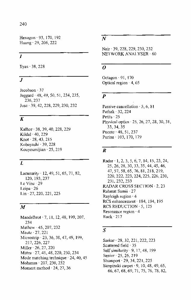
240
Hexagon' 93, 170, 192 Huang' 29, 206, 222
I
Ilyas . 38, 228
J
Jacobson' 37 Jaggard' 48,49,50,51,234,235,
236,237 Jose' 39, 42, 228, 229, 230, 232
K
Kalhor' 38, 39, 40, 228, 229 Kildal . 40, 229 Knot· 28,43,215 Kobayashi· 39,228 Kouyoumijian . 25, 219
L
Lacunarity- 12,49,51,65,71,82, 120, 193,237
Le Vine' 29 Leipa' 26 Lin' 27,220,221,225
M
Mandelbrot· 7, 11, 12,48, 199,207, 234
Mathew . 45, 207, 232 Mautz· 27, 221 Microstrip' 23, 36, 38, 47, 49, 199,
217,226,227 Miller' 26, 27, 220 Mittra . 27,41,48,220,230,234 Mode matching technique' 24, 40, 45 Mohanan' 207, 230,232 Moment method' 24,27,36
N
Nair' 39,228,229,230,232 NETWORK ANALYSER' 60
o Octagon . 91, 170 Optical region' 4, 65
p
Passive cancellation' 5, 6, 81 Pathak . 32, 224 Petits' 25 Physical optics' 25, 26, 27, 28, 30, 31,
33,34,35 Puente' 48, 51, 237 Purina . 103, 170, 179
R
Radar' 1,2,3,5,6, 7, 14, 15,23,24, 25,26,28,30,33,35,44,45,46, 47,57,58,65,76,81,218,219, 220,222,223,224,225,226,230, 231,232,233
RADAR CROSS SECTION· 2, 23 Rahmat Samii . 27 Rayleigh region' 4 RCS enhancement· 184, 194, 195 RCS REDUCTION' 5 125 , Resonance region' 4 Ruck' 217
s Sarkar . 28, 32, 221, 222, 223 Scattered tield . 35 Self similarity· 9, 17,48, 199 Senior' 25,26,219 Shumpert . 29,34, 221,225 Sierpinski carpet· 9, 10,48,49,65,
66,67,68,69,71,75,76,78,82,
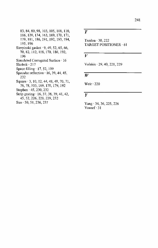
83, 84, 89,98, 103, 105, 108, 110, 116,120,134,163,169,170,171, 179,181,186,191,192,193,194, 195,196
Sierpinski gasket - 9,49, 52, 65, 66, 70, 82, 112, 118, 170, 186, 192, 196
Simulated Corrugated Surface - 16 Skolnik - 217 Space filling - 17, 52, 199 Specular ret1ection - 16,39,44,45,
232 Square- 3,10,12,44,48,49,70,71,
76,78,103,169,170,179,192 Stephen -45, 230, 232 Strip grating - 16,37,38,39,41,42,
45,52,226,228,229,232 Sun - 50, 51, 236, 237
T
Tandon - 30, 222 TARGET POSITIONER - 61
v Volakis - 29,40,221,229
w Weir - 220
y
Yang-34,36,225,226 Yousef- 31
241
242
List of publications of the author
International Journal
1. A. R. Chandran, M. Gopikrishna, C.K. Aanandan, P. Mohanan and
K.Vasudevan, "Radar Cross Section enhancement of dihedral corner
reflector using fractal based metallo-dielectric structures" lEE Electronics
Letters., Vol. 42. NO.2. September 28, 2006. pp. 1135-1136.
2. A. R. Chandran, T. Mathew, C.K. Aanandan, P. Mohanan and
K.Vasudevan, "Frequency tunable metallo-diectric structure for
backscattering reduction" lEE Electronics Letters., Vol. 40. No.20.
September 30, 2004.pp. 1245-1246.
3. A. R. Chandran, T. Mathew, C. K. Aanandan, P. Mohanan and K.
Vasudevan, "Low Backscattered Dual-Polarised Metallo-Dielectric Structure
Based on Sierpinski Carpet", Microwave and Optical Technology
Letters., Vol. 40. No.3. February 2004, pp. 246 - 248.
4. A. R. Chandran, M. Gopikrishna, C.K. Aanandan, P. Mohanan and
K.Vasudevan, "Scattering behaviour of fractal based metallo-dielectric
structures" Progress in Electromagnetic Research, PIER 69, 2007, pp.
323 - 339.
5. M. Gopikrishna, D. D. Krishna, A. R. Chandran and C. K. Aanandan,
"Band notched planar square monopole Antenna for UWB systems"
Journal of Electromagnetic waves and applications (JEMWA), Vol
21, No. 11,2007, 1525 - 1537.
International Conference
1. A. R. Chandran, T. Mathew, C. K. Aanandan, P. Mohanan and K.
Vasudevan, "Low Backscattered Dual polarized Metallo-Dielectric
Structure Based on Fractal Geometry", IEEE APS 2003 Int Symp
USNC/CNC/URSI, North Amer. Radio Sci. Mtg, Columbus, OH, USA. Vol.4,
June 2003, pp. 315 - 318.
2. A. R. Chandran, Thomaskutty Mathew, C. K. Aanandan, P. Mohanan and
K. Vasudevan, "Backscattering Reduction Using Fractal Based Metallo-

243
Dielectric Structure", Proc. PIERS 2003, Honolulu, Hawaii, USA, Oct
2003, Pp. 663.
3. Shynu S.V, Rohith K. Rat A. R. Chandran, C. K. Aanandan, P. Mohanan
and K. Vasudevan, "Single-Feed Dual-Frequency Dual Polarized Microstrip
Antenna with Hexagonal Slot, IEEE APS 2004 Int. Symp
USNC/CNC/URSI, Monterey, California, USA, June 2004, pp. 4380-4383.
4. Anupam R. Chandran, Thomaskutty. Mathew, Sona O. Kundukulam, C.
K. Aanandan, P. Mohanan and K. Vasudevan/' Multi-band Characteristic
of a Fractal Based Metal/o-dielectric Structure for Backscattering
reduction/, Proc. of Asia Pacific Microwave Conference (APMC-04)
1nt. Symp. New Delhi, INDIA. 15-18 December, 2004. pp. 580-
581(APMC/04/C/66).
5. A. R. Chandran, Thomaskutty. Mathew, C. K. Aanandan, P. Mohanan and
K. Vasudevan, "Metallo-Dielectric Structures for backscattering reduction",
IEEE APS 2005 Int Symp USNC/CNC/URS1, North Amer. Radio Sci. Mtg,
Washington DC, USA, July 2005, pp. 7803-8883.
6. Anupam R. Chandran, Thomaskutty. Mathew, C. K. Aanandan, P.
Mohanan and K. Vasudevan, "Superstrate Loaded Metallo-Dielectric
Structure Based On Fractal Geometry" Proceeding on The 5 th
International Conference on ITS Telecommunications (itst 2005t ,
Brest, FRANCE, 27-29 June.
7 Anupam R. Chandran, Gopikrishna M, C.K. Aanandan, P. Mohanan and
K. Vasudevan , "Sierpinski gasket based fractal structure for Radar Cross
Section reduction with frequency tunability" International Conference on
Microwaves, Antennas, Propagation and Remote Sensing (ICMARS-2006)
20-22 December, Jodhpur, India.
8. D. D. Krishna, A. R. Chandran and C. K. Aanandan, "A Compact Dual
Frequency Antenna with Sierpinski Gasket Based Slots" European
Microwave conference 2007 (EURAD 07) accepted.
9. A. R. Chandran, M. Gopikrishna, C. K. Aanandan, P. Mohanan and K.
Vasudevan, "Filter design using Cantor bar based Metal/a-dielectric
Structure/' Proc. of Asia Pacific Microwave Conference (APMC-07)
1nt. Symp. Thailand, December 11-14, 2007 (communicated).
244
National Conference
1. Anupam R. Chandran, Thomaskutty. Mathew, C. K. Aanandan, P.
Mohanan and K. Vasudevan, "Scattering Behaviour of Metal/a-Dielectric
Structure Based On Fractal Geometry", Proceedings of National
Symposium on Antennas and Propagation (APSYM-2002), 9-11
December, Cochin, India, pp.148-151, 2002.
2. Anupam R. Chandran, Thomaskutty Mathew, C.K. Aanandan, P.
Mohanan K.Vasudevan and K.G. Nair, " On the effect of loading
superstrate on a Metal/a-Dielectric Structure based on Sierpinski Gasket",
Proceedings of National Symposium on Antennas and Propagation
(APSYM-2004), 21-23 December, Cochin, India, pp .94-97, 2004.
3. M. Gopikrishna, D. D. Krishna, A. R. Chandran and C. K. Aanandan, "5
GHz WLAN band notched square monopole antenna for UWB systems"
Proceedings of National Symposium on Antennas and Propagation
(APSYM-2006), 14 - 16 December, Cochin, India, pp. 47-50, 2006.
245
Resume of the author
Anupam R. Chandran Senior Research Fellow Centre for Research in Electromagnetics and Antennas Department of Electronics Cochin University of Science and Technology Kochi-22, Kerala, India Tel: +91-484-2576418, Mob: +91-9447475614 Fax: +91-484-2575800 Email: [email protected]@yahoo.com
OBJECTIVE
To pursue research activities in the field of Radar Cross Section studies, frequency selective surfaces and microstrip antennas.
EDUCATION
M. Sc Applied Electronics (2001) PSG College of Arts and Sciences Bharathiar University Coiambatore Tamil Nadu India Class: First Class
B. Sc Applied Electronics (1998) College of Applied Sciences Mavelikkara Kerala University Kerala India Class: First Class
PROJECTS/TRAINING
1. Actively involved in development of an RCS measurement facility and its automation at Dept. of Electronics, Cochin University, Cochin, Kerala.
2. Successfully completed a project entitled "Development of Multi-functional single chip telephone" done at BPL Telecom Ltd. PaJakkad, Kerala India.

246
3. Successfully completed a project entitled "Interfacing 12-bit Serial ADC with 16C84 PlC microcontroller" done at PSG College of Arts and Science, Coimbatore India.
4. Attended State level workshop on "Recent Trends in Biomedical Instrumentation" held at PSG College of Arts and Science, Coimbatore, India from March 27 to March 29, 2000.
6. Attended National conference on Antennas and Propagation (APSYM 2002 held at Cochin, India) and presented paper.
7. Attended National conference on Ocean Electronics (SYMPOL 2003 held at Cochin, India)
8. Attended National conference on Antennas and Propagation (APSYM 2004 held at Cochin, India) and presented paper.
9. Attended National conference on Ocean Electronics (SYMPOL 2005 held at Cochin, India)
10. Attended workshop on LabVilEW conducted by National Instruments at Sophisticated Test and Instrumentation Centre, Cochin University, Kochi, India.
11. Attended National conference on Antennas and Propagation (APSYM 2006 held at Cochin, India)
COMPUTER SKILLS
Languages
C++, FORTRAN Assembly language programming 8085,8051, PlC 16F84
Operating Systems
Windows 9x, Windows 2000, Windows XP, Macintosh.
RF Tools
Zealand IE3D, Ansoft HFSS, Ansoft Designer
Scientific Applications
Mat/ab, Mathematica, Sigma plot, LabVIEW 8
Computer Hardware
Cert(fication in Diploma in Computer Hardware Engineering with 'A . grade from Drishna Technologies, Cochin, India.
![Research on garment pattern design based on …...geometry is also called geometry describing nature [ 7]. After that, fractal design, fractal information, fractal art, and other applications](https://img.pdfslide.us/doc/110x75/5e81482453849554aa2fa807/research-on-garment-pattern-design-based-on-geometry-is-also-called-geometry.jpg)