Embed Size (px)
Citation preview
Progress In Electromagnetics Research, PIER 69, 323–339, 2007
SCATTERING BEHAVIOUR OF FRACTAL BASEDMETALLO-DIELECTRIC STRUCTURES
A. R. Chandran, M. Gopikrishna, C. K. AanandanP. Mohanan and K. Vasudevan
Centre for Research in Electromagnetics and AntennasDepartment of ElectronicsCochin University of Science and TechnologyCochin 682 022, India
Abstract—The scattering behaviour of fractal based metallo-dielectric structures loaded over metallic targets of different shapessuch as flat plate, cylinder and dihedral corner reflector are investigatedfor both TE and TM polarizations of the incident wave. Out of thevarious fractal structures studied, square Sierpinski carpet structureis found to give backscattering reduction for an appreciable range offrequencies. The frequency of minimum backscattering depends on thegeometry of the structure as well as on the thickness of the substrate.This structure when loaded over a dihedral corner reflector is showingan enhancement in RCS for corner angles other than 90◦.
1. INTRODUCTION
Fractal has found an intricate place in science as a representationof some of the unique geometrical features occurring in nature.Fractal geometry is described as an arrangement of identical orsimilar elements repeated in different magnifications, orientationsand positions. There are a number of geometric properties usedto depict fractals [1]; self similarity, fractional dimension and thespace filling property. The blend of fractal geometry and theory ofelectromagnetism paved the way to a new research area known asfractal electrodynamics. Structures based on fractal geometries arefinding applications especially in the design of antennas for multibandapplications, due to their inherent self similarity and space fillingproperties [2, 3]. The Sierpinski antenna was the first example of amulti band radiator based on fractal geometry. These antennas keepthe same behaviour at several bands in terms of input impedance
324 Chandran et al.
and radiation pattern. It features as many bands as scales levels ingeometry [4, 5]. Some of the other areas of study include frequencyselective surfaces, diffraction by band limited fractal screens, thereflection and transmission properties of fractal multilayers, the sidelobe computation of fractal arrays, the scattering of electromagneticwave from corrugated random surfaces with fractal slopes etc. [6–10].
The study of radar cross section (RCS) is of great importanceas it is used in modeling many portions of aircrafts and missiles.The development of smart radar systems triggered the scientiststo the field of radar cross section reduction during the past fewyears. Recent interest in RCS is to reduce the detectability oftargets. Elimination of specular reflection over a wide range of aspectangle using a strip grating surface of two dimensional periodicity forTE polarization is reported in [11]. Studies for the elimination ofbackscattering and specular reflections were studied extensively bymany researchers [12, 13]. All these structures employ metallizationbased on conventional Euclidean geometry backed by a flat metallicplate.
Electromagnetic scattering problems of perfectly conductingcylinder and parallel metamaterial cylinders are studied in [14, 15].RCS of a target with lossy background has been calculated usingparabolic equation method in [16]. In order to show the validity ofthe method the RCS of a conducting cylinder computed using theparabolic equation method is compared with the analytic results.Various techniques are available in the literature for the reductionof RCS of cylindrical bodies. The method of loading impedanceas a means of controlling the RCS of objects has been extensivelyinvestigated by many researchers. This technique consists of loadingthe body with lumped or distributed impedances. Its main objectiveis to calculate the optimum impedance and to position it in the objectin order to attain the necessary control of RCS. The minimizationof backscattering of a cylinder by loading lumped impedances at twopoints is reported in [17]. The technique for minimizing the RCSof a moderated cylindrical structure using central impedance loadinghas been discussed in [18]. Michielssen et al. have reported thereduction of RCS of solid dielectric cylinders using simulated annealingtechnique [19]. Electromagnetic scattering from corrugated cylindersof circular cross section has been described in [20]. Arvas et al. havereported RCS of dielectric and conducting cylinders of arbitrary crosssection using the method of moments [21].
Missiles and aircrafts are complex targets that can be representedas collections of basic geometric elements such as cylinders, conesand flat plates. Studies of the backscattering cross section of corner
Progress In Electromagnetics Research, PIER 69, 2007 325
reflectors are important for many radar applications and are often usedas an RCS standard. Corner reflectors are inadvertently formed onships and military vehicles wherever flat surfaces meet at right anglesand form major scattering centers of these objects. They are highlyretrodirective and the return persists in angles. An aircraft dihedraleffect involves the upper surface of the wing and the curved side of thefuselage. Another similar dihedral occurs between the upper surfaceof the horizontal stabilizer and the side of the tail fin. Dihedralsincrease the probability of radar detection. Right angled dihedralcorner reflector provides a large radar cross section over a wide angularrange in a plane normal to its wedge, which makes it a suitable referencetarget in remote sensing and synthetic aperture radar applications.These large echoes from these targets arise from multiple reflectionsbetween the two mutually orthogonal flat surfaces dominating thebackscattered pattern in forward region, forming the reflectors [22–25]. In recent years several papers dealing with the backscatteringby perfectly conducting as well as loaded dihedral corner reflectorstructures have been published. Dihedral corners have been proposedby many workers in RCS reduction studies and also in RCS calibrationtarget [26–29]. It has also been reported that RCS reduction of dihedralcorners can be achieved by altering the mutual orthogonality of the flatsurfaces [30]. This technique involves changes in original engineeringdesign of the target. The consequence of non orthogonality on thescattering properties have been analysed in [31].
The large RCS of a 90◦ dihedral corner over a wide angular rangemakes it a suitable reference target in remote sensing and syntheticaperture radar applications. The RCS of dihedral corner reflector withacute and obtuse corner angles are less. A slight variation from the 90◦corner angle reduces the RCS drastically. This is a major drawbackin designing corner reflectors for the applications aforementioned. Thebackscattered power is appreciably lower for dihedral corner reflectorwith corner angle other than 90◦.
Recently the authors have reported the use of fractal basedmetallization for the elimination of backscattered power from targets.The maximum reduction in backscattered power is obtained when themetallization is based on the third iterated stage of Sierpinski carpetfractal geometry [32]. The frequency tunability is also possible inthis type of structure [33]. This paper deals with the study of thescattering behaviour of different targets such as metallic flat plate,cylinder surface and dihedral corner reflector loaded with metallo-dielectric structures (MDS) based on fractal geometries. The studyencompasses three parts. First, the scattering behaviour of Sierpinskicarpet fractal structures with different basic geometries etched on
326 Chandran et al.
substrates of different thickness is presented along with a description ofthe measurement setup. The second part deals with the backscatteringproperties of a cylinder loaded with Sierpinski carpet fractal structureand finally the effect of fractal loading over dihedral corner reflector isdiscussed.
2. METHODOLOGY
The metallo-dielectric structures based on fractal geometries arefabricated by photo etching the metallizations on a dielectric sheet(ε = 2.56) of size 30 × 30 cm2 and thickness h. The targets ofinterest (metallic flat plate, metallic cylinder and dihedral cornerreflector) are loaded with these metallo-dielectric structures and placedon a turn table inside an anechoic chamber. The structure isilluminated using a horn antenna and the backscattered power ismeasured using an identical horn antenna kept at the side of thetransmitter. The backscattered power at various angles of incidenceis measured by rotating the target. The measurements are performedusing an HP 8510C network analyzer. The backscattered power fromthese structures is compared with that of unloaded targets of samedimension.
3. FLAT PLATE
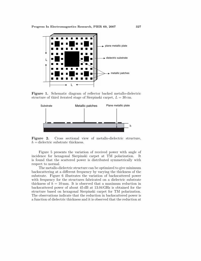
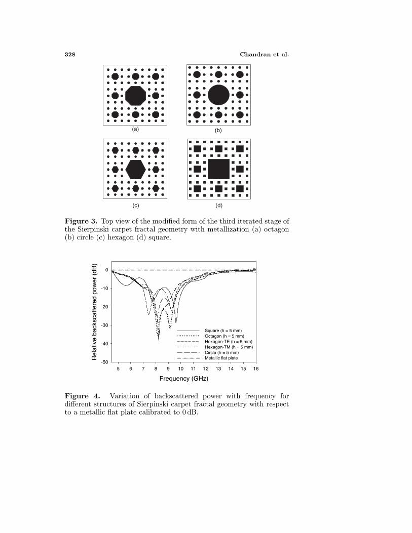
Scattering properties of a flat plate loaded with metallo-dielectricstructures are discussed in this section. The schematic of reflectorbacked metallo-dielectric structure and its cross sectional view areshown in Figures 1 and 2 respectively. Top view of the third iteratedstage of Sierpinski carpet fractal geometry using different generatorslike octagon, circle, hexagon and square are shown in Figure 3.
The variation of backscattered power with frequency for differentstructures in the frequency range from 4.5 GHz to 16 GHz is illustratedin Figure 4. From the graph it is seen that out of various carpetstructures, hexagonal Sierpinski carpet is giving a maximum reductionin backscattered power of ∼38 dB at 8.24 GHz for TM polarization for adielectric thickness h = 5 mm. Also, this structure is giving a reductionin backscattered power over an appreciable range of frequencies in X-band. Since the structure is not symmetric, the backscattered powerobtained is different for TE polarization. A maximum bandwidth(below −10 dB) of 2.83 GHz is obtained by using square Sierpinskicarpet simultaneously for both TE and TM, since the structure issymmetrical.
Progress In Electromagnetics Research, PIER 69, 2007 327
metallic patches
plane metallic plate
dielectric substrateL
L
Figure 1. Schematic diagram of reflector backed metallo-dielectricstructure of third iterated stage of Sierpinski carpet, L = 30 cm.
Plane metallic plate Substrate Metallic patches
h
Figure 2. Cross sectional view of metallo-dielectric structure,h = dielectric substrate thickness.
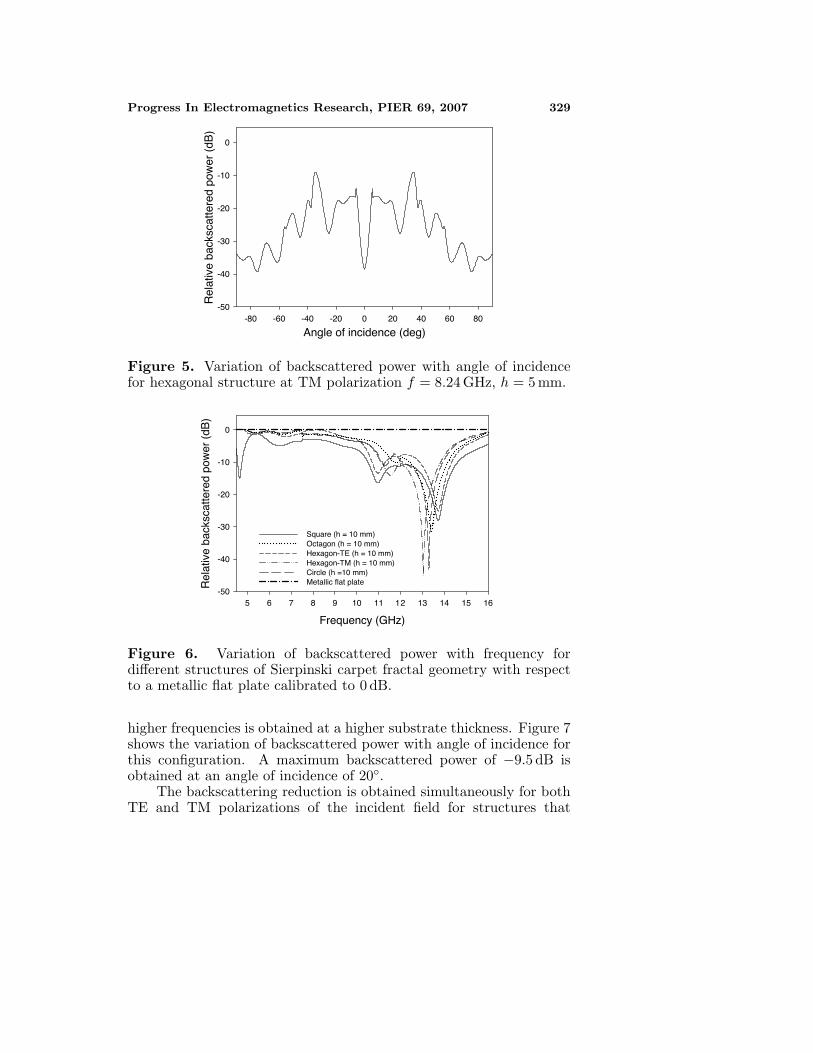
Figure 5 presents the variation of received power with angle ofincidence for hexagonal Sierpinski carpet at TM polarization. Itis found that the scattered power is distributed symmetrically withrespect to normal.
The metallo-dielectric structure can be optimized to give minimumbackscattering at a different frequency by varying the thickness of thesubstrate. Figure 6 illustrates the variation of backscattered powerwith frequency for the structures fabricated on a dielectric substratethickness of h = 10 mm. It is observed that a maximum reduction inbackscattered power of about 45 dB at 13.04 GHz is obtained for thestructure based on hexagonal Sierpinski carpet for TM polarization.The observations indicate that the reduction in backscattered power isa function of dielectric thickness and it is observed that the reduction at
328 Chandran et al.
(b)
(c)
(a)
(d)
Figure 3. Top view of the modified form of the third iterated stage ofthe Sierpinski carpet fractal geometry with metallization (a) octagon(b) circle (c) hexagon (d) square.
Frequency (GHz)
5 6 7 8 9 10 11 12 13 14 15 16
Rel
ativ
e ba
cksc
atte
red
pow
er (
dB)
-50
-40
-30
-20
-10
0
Square (h = 5 mm)Octagon (h = 5 mm)Hexagon-TE (h = 5 mm)Hexagon-TM (h = 5 mm)Circle (h = 5 mm)Metallic flat plate
Frequency (GHz)
5 6 7 8 9 10 11 12 13 14 15 16
Rel
ativ
e ba
cksc
atte
red
pow
er (
dB)
-50
-40
-30
-20
-10
0
Square (h = 5 mm)Octagon (h = 5 mm)Hexagon-TE (h = 5 mm)Hexagon-TM (h = 5 mm)Circle (h = 5 mm)Metallic flat plate
Figure 4. Variation of backscattered power with frequency fordifferent structures of Sierpinski carpet fractal geometry with respectto a metallic flat plate calibrated to 0 dB.
Progress In Electromagnetics Research, PIER 69, 2007 329
Angle of incidence (deg)-80 -60 -40 -20 0 20 40 60 80
Rel
ativ
e ba
cksc
atte
red
pow
er (
dB)
-50
-40
-30
-20
-10
0
Figure 5. Variation of backscattered power with angle of incidencefor hexagonal structure at TM polarization f = 8.24 GHz, h = 5 mm.
Frequency (GHz)
5 6 7 8 9 10 11 12 13 14 15 16
Rel
ativ
e ba
cksc
atte
red
pow
er (
dB)
-50
-40
-30
-20
-10
0
Square (h = 10 mm)Octagon (h = 10 mm)Hexagon-TE (h = 10 mm)Hexagon-TM (h = 10 mm)Circle (h =10 mm)Metallic flat plate
Figure 6. Variation of backscattered power with frequency fordifferent structures of Sierpinski carpet fractal geometry with respectto a metallic flat plate calibrated to 0 dB.
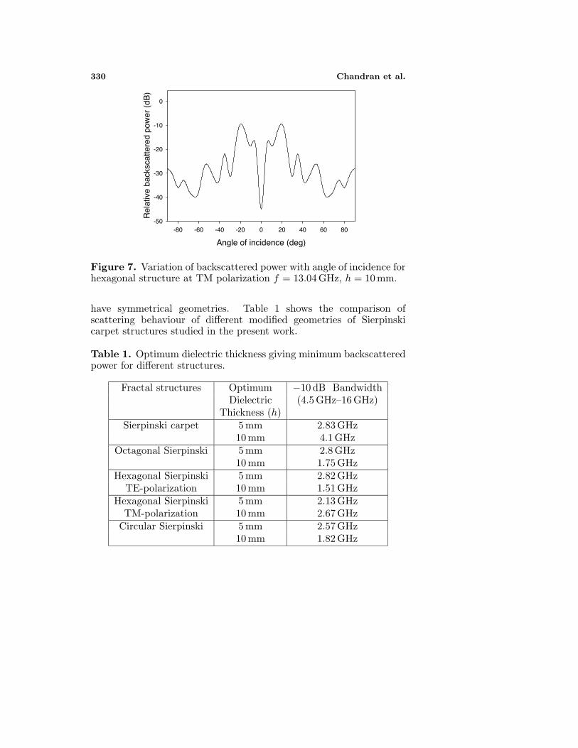
higher frequencies is obtained at a higher substrate thickness. Figure 7shows the variation of backscattered power with angle of incidence forthis configuration. A maximum backscattered power of −9.5 dB isobtained at an angle of incidence of 20◦.
The backscattering reduction is obtained simultaneously for bothTE and TM polarizations of the incident field for structures that
330 Chandran et al.
Angle of incidence (deg)
-80 -60 -40 -20 0 20 40 60 80
Rel
ativ
e ba
cksc
atte
red
pow
er (
dB)
-50
-40
-30
-20
-10
0
Figure 7. Variation of backscattered power with angle of incidence forhexagonal structure at TM polarization f = 13.04 GHz, h = 10 mm.
have symmetrical geometries. Table 1 shows the comparison ofscattering behaviour of different modified geometries of Sierpinskicarpet structures studied in the present work.
Table 1. Optimum dielectric thickness giving minimum backscatteredpower for different structures.
Fractal structures Optimum −10 dB BandwidthDielectric (4.5 GHz–16 GHz)
Thickness (h)Sierpinski carpet 5 mm 2.83 GHz
10 mm 4.1 GHzOctagonal Sierpinski 5 mm 2.8 GHz
10 mm 1.75 GHzHexagonal Sierpinski 5 mm 2.82 GHz
TE-polarization 10 mm 1.51 GHzHexagonal Sierpinski 5 mm 2.13 GHz
TM-polarization 10 mm 2.67 GHzCircular Sierpinski 5 mm 2.57 GHz
10 mm 1.82 GHz
Progress In Electromagnetics Research, PIER 69, 2007 331
4. METALLIC CYLINDER
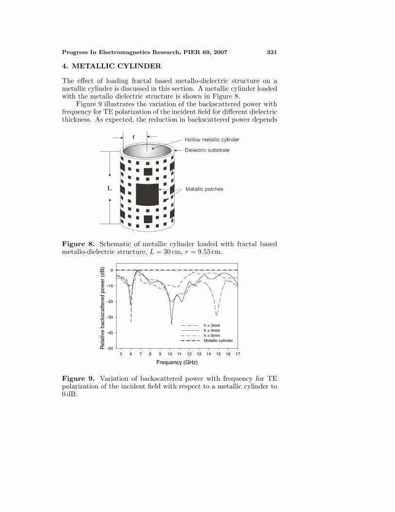
The effect of loading fractal based metallo-dielectric structure on ametallic cylinder is discussed in this section. A metallic cylinder loadedwith the metallo dielectric structure is shown in Figure 8.
Figure 9 illustrates the variation of the backscattered power withfrequency for TE polarization of the incident field for different dielectricthickness. As expected, the reduction in backscattered power depends
L
r
Figure 8. Schematic of metallic cylinder loaded with fractal basedmetallo-dielectric structure, L = 30 cm, r = 9.55 cm.
Frequency (GHz)
5 6 7 8 9 10 11 12 13 14 15 16 17
Rel
ativ
e ba
cksc
atte
red
pow
er (
dB)
-50
-40
-30
-20
-10
0
h = 3mm h = 4mm h = 5mm Metallic cylinder
Figure 9. Variation of backscattered power with frequency for TEpolarization of the incident field with respect to a metallic cylinder to0 dB.

332 Chandran et al.
Angle of incidence (deg)
-80 -60 -40 -20 0 20 40 60 80
Rel
ativ
e ba
cksc
atte
red
pow
er (
dB)
-50
-40
-30
-20
-10
0
Figure 10. Backscattered power with angle of incidence f =10.18 GHz, h = 4 mm, TE polarization.
Frequency (GHz)
5 6 7 8 9 10 11 12 13 14 15 16 17
Rel
ativ
e ba
cksc
atte
red
pow
er (
dB)
-50
-40
-30
-20
-10
0
h = 3mm h = 4mm h = 5mm Metallic cylinder
Figure 11. Backscattered power variation with frequency for TMpolarization of the incident field with respect to a metallic cylindercalibrated to 0 dB.
on the thickness of the substrate material. A reduction of ∼ 35 dBin the backscattered power is obtained at 10.18 GHz for a dielectricthickness = 4 mm. The frequency of minimum backscattered power isalso changing with thickness of the substrate. Backscattered powerfor different angles of incidence for the configuration giving minimumbackscattered power is plotted in Figure 10. It is found that, at anangle of incidence of 15◦, backscattering is maximum.
Progress In Electromagnetics Research, PIER 69, 2007 333
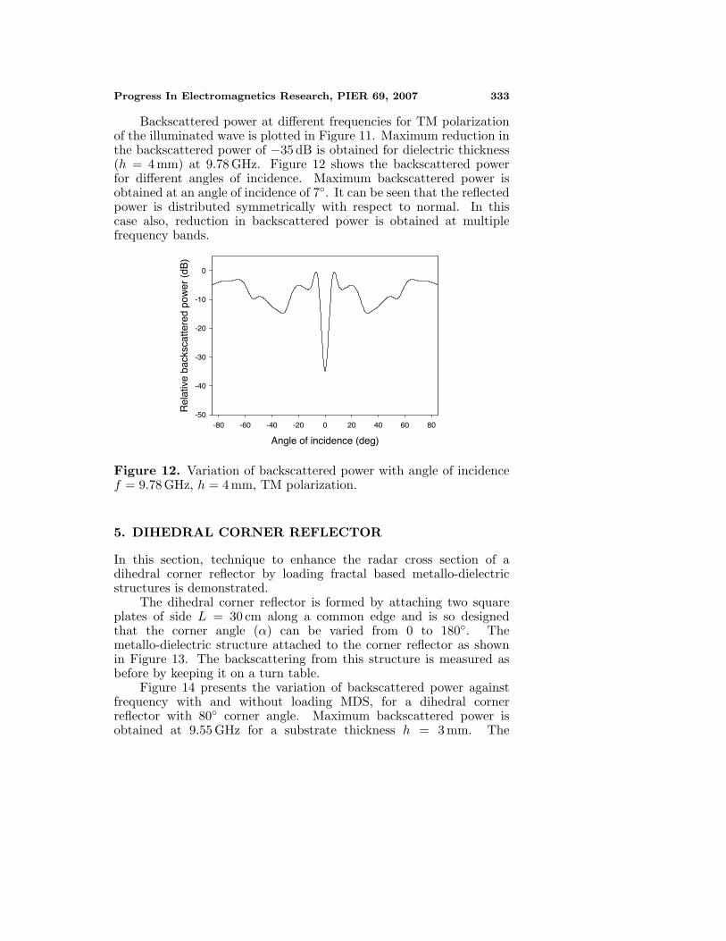
Backscattered power at different frequencies for TM polarizationof the illuminated wave is plotted in Figure 11. Maximum reduction inthe backscattered power of −35 dB is obtained for dielectric thickness(h = 4 mm) at 9.78 GHz. Figure 12 shows the backscattered powerfor different angles of incidence. Maximum backscattered power isobtained at an angle of incidence of 7◦. It can be seen that the reflectedpower is distributed symmetrically with respect to normal. In thiscase also, reduction in backscattered power is obtained at multiplefrequency bands.
Angle of incidence (deg)
-80 -60 -40 -20 0 20 40 60 80
Rel
ativ
e ba
cksc
atte
red
pow
er (
dB)
-50
-40
-30
-20
-10
0
Figure 12. Variation of backscattered power with angle of incidencef = 9.78 GHz, h = 4 mm, TM polarization.
5. DIHEDRAL CORNER REFLECTOR
In this section, technique to enhance the radar cross section of adihedral corner reflector by loading fractal based metallo-dielectricstructures is demonstrated.
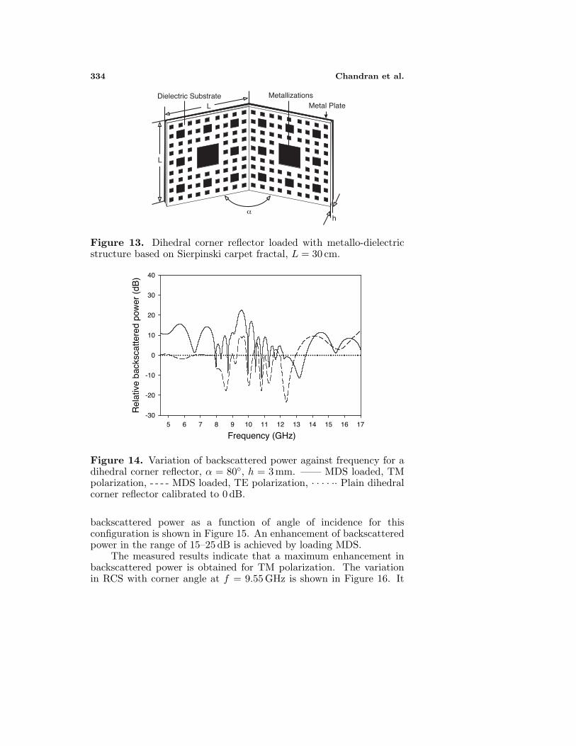
The dihedral corner reflector is formed by attaching two squareplates of side L = 30 cm along a common edge and is so designedthat the corner angle (α) can be varied from 0 to 180◦. Themetallo-dielectric structure attached to the corner reflector as shownin Figure 13. The backscattering from this structure is measured asbefore by keeping it on a turn table.
Figure 14 presents the variation of backscattered power againstfrequency with and without loading MDS, for a dihedral cornerreflector with 80◦ corner angle. Maximum backscattered power isobtained at 9.55 GHz for a substrate thickness h = 3 mm. The
334 Chandran et al.
L
L
h
Metal PlateMetallizationsDielectric Substrate
α
Figure 13. Dihedral corner reflector loaded with metallo-dielectricstructure based on Sierpinski carpet fractal, L = 30 cm.
Frequency (GHz)5 6 7 8 9 10 11 12 13 14 15 16 17
Rel
ativ
e ba
cksc
atte
red
pow
er (
dB)
-30
-20
-10
0
10
20
30
40
Figure 14. Variation of backscattered power against frequency for adihedral corner reflector, α = 80◦, h = 3 mm. —— MDS loaded, TMpolarization, - - - - MDS loaded, TE polarization, · · · · ·· Plain dihedralcorner reflector calibrated to 0 dB.
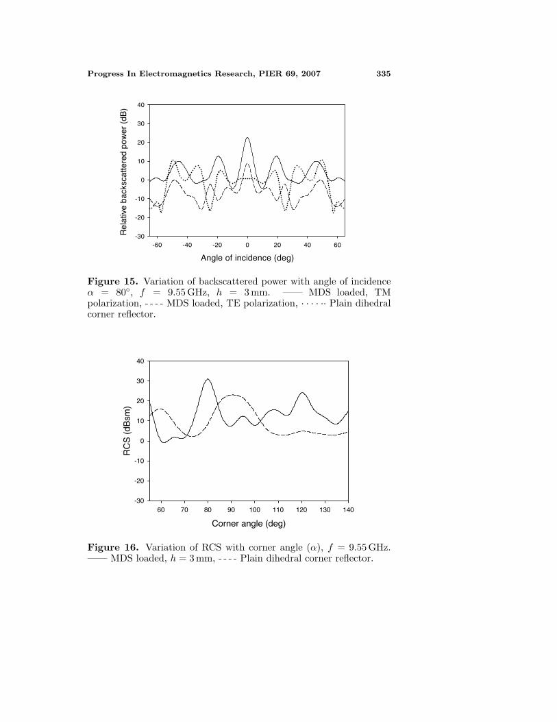
backscattered power as a function of angle of incidence for thisconfiguration is shown in Figure 15. An enhancement of backscatteredpower in the range of 15–25 dB is achieved by loading MDS.
The measured results indicate that a maximum enhancement inbackscattered power is obtained for TM polarization. The variationin RCS with corner angle at f = 9.55 GHz is shown in Figure 16. It
Progress In Electromagnetics Research, PIER 69, 2007 335
Angle of incidence (deg)
-60 -40 -20 0 20 40 60
Rel
ativ
e ba
cksc
atte
red
pow
er (
dB)
-30
-20
-10
0
10
20
30
40
Figure 15. Variation of backscattered power with angle of incidenceα = 80◦, f = 9.55 GHz, h = 3 mm. —— MDS loaded, TMpolarization, - - - - MDS loaded, TE polarization, · · · · ·· Plain dihedralcorner reflector.
Corner angle (deg)
60 70 80 90 100 110 120 130 140
RC
S (
dBsm
)
-30
-20
-10
0
10
20
30
40
Figure 16. Variation of RCS with corner angle (α), f = 9.55 GHz.—— MDS loaded, h = 3 mm, - - - - Plain dihedral corner reflector.
336 Chandran et al.
is clear from the graph that RCS enhancement is obtained at certainacute and obtuse corner angles of the dihedral corner reflector whenMDS is loaded. The results also show that, maximum enhancementin RCS of 20–30 dBsm is obtained for TM polarization of the incidentfield, for certain corner angles.
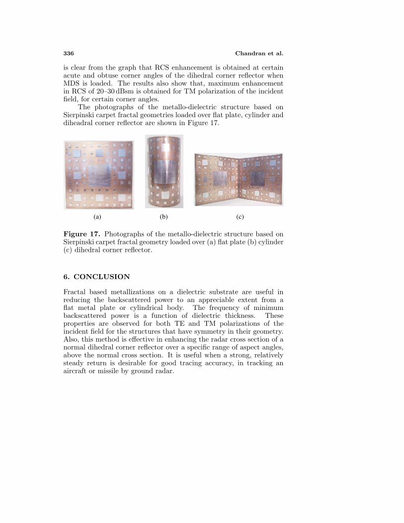
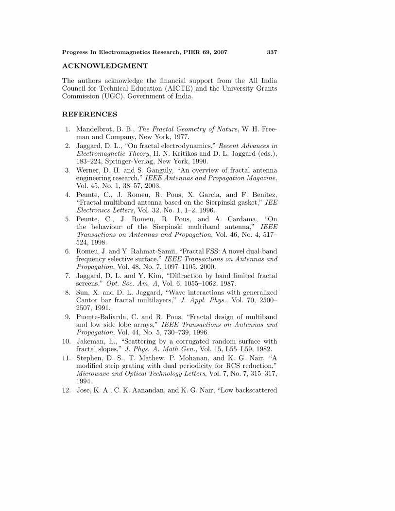
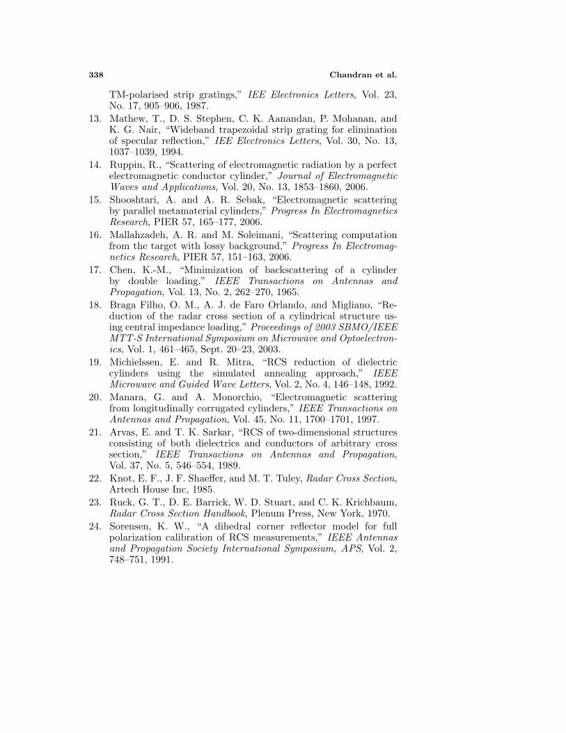
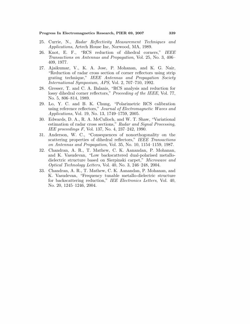
The photographs of the metallo-dielectric structure based onSierpinski carpet fractal geometries loaded over flat plate, cylinder anddiheadral corner reflector are shown in Figure 17.
(a) (b) (c)
Figure 17. Photographs of the metallo-dielectric structure based onSierpinski carpet fractal geometry loaded over (a) flat plate (b) cylinder(c) dihedral corner reflector.
6. CONCLUSION
Fractal based metallizations on a dielectric substrate are useful inreducing the backscattered power to an appreciable extent from aflat metal plate or cylindrical body. The frequency of minimumbackscattered power is a function of dielectric thickness. Theseproperties are observed for both TE and TM polarizations of theincident field for the structures that have symmetry in their geometry.Also, this method is effective in enhancing the radar cross section of anormal dihedral corner reflector over a specific range of aspect angles,above the normal cross section. It is useful when a strong, relativelysteady return is desirable for good tracing accuracy, in tracking anaircraft or missile by ground radar.
Progress In Electromagnetics Research, PIER 69, 2007 337
ACKNOWLEDGMENT
The authors acknowledge the financial support from the All IndiaCouncil for Technical Education (AICTE) and the University GrantsCommission (UGC), Government of India.
REFERENCES
1. Mandelbrot, B. B., The Fractal Geometry of Nature, W. H. Free-man and Company, New York, 1977.
2. Jaggard, D. L., “On fractal electrodynamics,” Recent Advances inElectromagnetic Theory, H. N. Kritikos and D. L. Jaggard (eds.),183–224, Springer-Verlag, New York, 1990.
3. Werner, D. H. and S. Ganguly, “An overview of fractal antennaengineering research,” IEEE Antennas and Propagation Magazine,Vol. 45, No. 1, 38–57, 2003.
4. Peunte, C., J. Romeu, R. Pous, X. Garcia, and F. Benitez,“Fractal multiband antenna based on the Sierpinski gasket,” IEEElectronics Letters, Vol. 32, No. 1, 1–2, 1996.
5. Peunte, C., J. Romeu, R. Pous, and A. Cardama, “Onthe behaviour of the Sierpinski multiband antenna,” IEEETransactions on Antennas and Propagation, Vol. 46, No. 4, 517–524, 1998.
6. Romeu, J. and Y. Rahmat-Samii, “Fractal FSS: A novel dual-bandfrequency selective surface,” IEEE Transactions on Antennas andPropagation, Vol. 48, No. 7, 1097–1105, 2000.
7. Jaggard, D. L. and Y. Kim, “Diffraction by band limited fractalscreens,” Opt. Soc. Am. A, Vol. 6, 1055–1062, 1987.
8. Sun, X. and D. L. Jaggard, “Wave interactions with generalizedCantor bar fractal multilayers,” J. Appl. Phys., Vol. 70, 2500–2507, 1991.
9. Puente-Baliarda, C. and R. Pous, “Fractal design of multibandand low side lobe arrays,” IEEE Transactions on Antennas andPropagation, Vol. 44, No. 5, 730–739, 1996.
10. Jakeman, E., “Scattering by a corrugated random surface withfractal slopes,” J. Phys. A. Math Gen., Vol. 15, L55–L59, 1982.
11. Stephen, D. S., T. Mathew, P. Mohanan, and K. G. Nair, “Amodified strip grating with dual periodicity for RCS reduction,”Microwave and Optical Technology Letters, Vol. 7, No. 7, 315–317,1994.
12. Jose, K. A., C. K. Aanandan, and K. G. Nair, “Low backscattered
338 Chandran et al.
TM-polarised strip gratings,” IEE Electronics Letters, Vol. 23,No. 17, 905–906, 1987.
13. Mathew, T., D. S. Stephen, C. K. Aanandan, P. Mohanan, andK. G. Nair, “Wideband trapezoidal strip grating for eliminationof specular reflection,” IEE Electronics Letters, Vol. 30, No. 13,1037–1039, 1994.
14. Ruppin, R., “Scattering of electromagnetic radiation by a perfectelectromagnetic conductor cylinder,” Journal of ElectromagneticWaves and Applications, Vol. 20, No. 13, 1853–1860, 2006.
15. Shooshtari, A. and A. R. Sebak, “Electromagnetic scatteringby parallel metamaterial cylinders,” Progress In ElectromagneticsResearch, PIER 57, 165–177, 2006.
16. Mallahzadeh, A. R. and M. Soleimani, “Scattering computationfrom the target with lossy background,” Progress In Electromag-netics Research, PIER 57, 151–163, 2006.
17. Chen, K.-M., “Minimization of backscattering of a cylinderby double loading,” IEEE Transactions on Antennas andPropagation, Vol. 13, No. 2, 262–270, 1965.
18. Braga Filho, O. M., A. J. de Faro Orlando, and Migliano, “Re-duction of the radar cross section of a cylindrical structure us-ing central impedance loading,” Proceedings of 2003 SBMO/IEEEMTT-S International Symposium on Microwave and Optoelectron-ics, Vol. 1, 461–465, Sept. 20–23, 2003.
19. Michielssen, E. and R. Mitra, “RCS reduction of dielectriccylinders using the simulated annealing approach,” IEEEMicrowave and Guided Wave Letters, Vol. 2, No. 4, 146–148, 1992.
20. Manara, G. and A. Monorchio, “Electromagnetic scatteringfrom longitudinally corrugated cylinders,” IEEE Transactions onAntennas and Propagation, Vol. 45, No. 11, 1700–1701, 1997.
21. Arvas, E. and T. K. Sarkar, “RCS of two-dimensional structuresconsisting of both dielectrics and conductors of arbitrary crosssection,” IEEE Transactions on Antennas and Propagation,Vol. 37, No. 5, 546–554, 1989.
22. Knot, E. F., J. F. Shaeffer, and M. T. Tuley, Radar Cross Section,Artech House Inc, 1985.
23. Ruck, G. T., D. E. Barrick, W. D. Stuart, and C. K. Krichbaum,Radar Cross Section Handbook, Plenum Press, New York, 1970.
24. Sorensen, K. W., “A dihedral corner reflector model for fullpolarization calibration of RCS measurements,” IEEE Antennasand Propagation Society International Symposium, APS, Vol. 2,748–751, 1991.
Progress In Electromagnetics Research, PIER 69, 2007 339
25. Currie, N., Radar Reflectivity Measurement Techniques andApplications, Artech House Inc, Norwood, MA, 1989.
26. Knot, E. F., “RCS reduction of dihedral corners,” IEEETransactions on Antennas and Propagation, Vol. 25, No. 3, 406–409, 1977.
27. Ajaikumar, V., K. A. Jose, P. Mohanan, and K. G. Nair,“Reduction of radar cross section of corner reflectors using stripgrating technique,” IEEE Antennas and Propagation SocietyInternational Symposium, APS, Vol. 2, 707–710, 1992.
28. Gresser, T. and C. A. Balanis, “RCS analysis and reduction forlossy dihedral corner reflectors,” Proceeding of the IEEE, Vol. 77,No. 5, 806–814, 1989.
29. Lo, Y. C. and B. K. Chung, “Polarimetric RCS calibrationusing reference reflectors,” Journal of Electromagnetic Waves andApplications, Vol. 19, No. 13, 1749–1759, 2005.
30. Edwards, D. A., R. A. McCulloch, and W. T. Shaw, “Variationalestimation of radar cross sections,” Radar and Signal Processing,IEE proceedings F, Vol. 137, No. 4, 237–242, 1990.
31. Anderson, W. C., “Consequences of nonorthogonality on thescattering properties of dihedral reflectors,” IEEE Transactionson Antennas and Propagation, Vol. 35, No. 10, 1154–1159, 1987.
32. Chandran, A. R., T. Mathew, C. K. Aanandan, P. Mohanan,and K. Vasudevan, “Low backscattered dual-polarised metallo-dielectric structure based on Sierpinski carpet,” Microwave andOptical Technology Letters, Vol. 40, No. 3, 246–248, 2004.
33. Chandran, A. R., T. Mathew, C. K. Aanandan, P. Mohanan, andK. Vasudevan, “Frequency tunable metallo-dielectric structurefor backscattering reduction,” IEE Electronics Letters, Vol. 40,No. 20, 1245–1246, 2004.