Embed Size (px)
Citation preview

METRA. THE WORLD’S BEST KITS.™
© COPYRIGHT 2004-2011 METRA ELECTRONICS CORPORATION
APPLICATIONS
1-800-221-0932 metraonline.com
INSTALLATION INSTRUCTIONS FOR PART 99-7423
REV.
5/7
/12
WIRING & ANTENNA CONNECTIONS (sold separately) Wiring Harness:• 70-7552 - Nissan harness 2007-upAntenna Adapter:• 40-NI12 - Nissan antenna adapter 2007-up
• Panel removal tool • Flat blade screwdriver • Phillips screwdriver • Torx screwdriver
TOOLS REQUIRED
Nissan Altima 2007-up99-7423
• A) Radio housing • B) Radio housing trim plate • C) Radio housing brackets • D) Double DIN trim plate • E) Double DIN brackets • F) ISO brackets • G) Pocket • H) (2) Climate control trim panels • I) (2) #8 3/8” screws
KIT FEATURES
KIT COMPONENTS
B CA
• DIN radio provision with pocket• ISO mount radio provision with pocket• Double DIN radio provision• Stacked ISO mount unit provision
D
I
F GE H
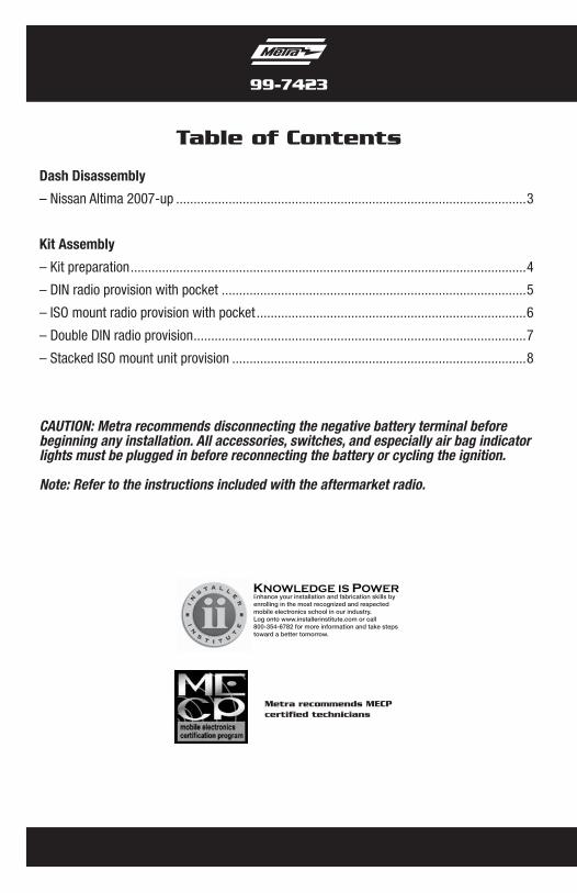
Table of Contents
Dash Disassembly
– Nissan Altima 2007-up ....................................................................................................3
Kit Assembly
– Kit preparation .................................................................................................................4
– DIN radio provision with pocket .......................................................................................5
– ISO mount radio provision with pocket .............................................................................6
– Double DIN radio provision ...............................................................................................7
– Stacked ISO mount unit provision ....................................................................................8
KNOWLEDGE IS POWEREnhance your installation and fabrication skills by enrolling in the most recognized and respected mobile electronics school in our industry.Log onto www.installerinstitute.com or call 800-354-6782 for more information and take steps toward a better tomorrow.
Metra recommends MECP certified technicians
99-7423
CAUTION: Metra recommends disconnecting the negative battery terminal before beginning any installation. All accessories, switches, and especially air bag indicator lights must be plugged in before reconnecting the battery or cycling the ignition.
Note: Refer to the instructions included with the aftermarket radio.
1. Unclip and remove trim panel between the shifter and the radio/climate control panel. (Figure A)
2. Remove (2) Phillips screws exposed behind panel below radio/climate control panel. (Figure A)
3. Unclip and remove the climate control vent trim panel then remove (2) Phillips screws exposed behind panel. (Figure B)
4. Unclip, unplug and remove entire radio/climate control panel. (Figure B)
5. Remove (5) T-20 Torx screws securing the radio/climate control brackets then unclip and remove the climate control.
Note: Retain the factory climate controls for reuse during kit assembly.
Continued to kit preparation
3
Nissan Altima 2007-up
Dash Disassembly 99-7423
(Figure A)
(Figure C)
PASSAIR BAG
(Figure B)
4
Kit Assembly 99-7423
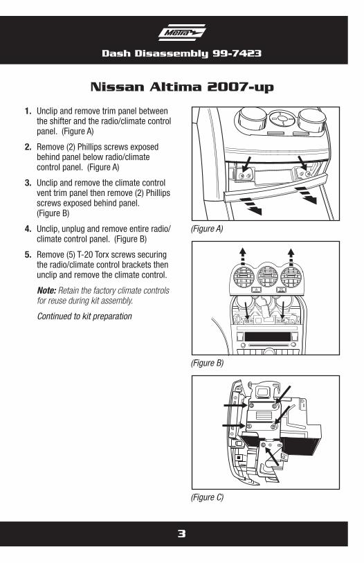
1. Clip the corresponding climate control trim panel into the radio housing. (Figure A)
Note: There are (2) different climate control trim panels. One for auto climate control and one for manual climate control.
2. Attach the (2) radio housing brackets to the climate controls using the factory screws. (Figure B)
3. Attach the bracket/climate control assembly to the radio housing using the (2) #8 3/8” screws supplied with this kit. (Figure C)
Continued to kit assembly
Kit preparation
(Figure A)
(Figure C)
(Figure B)
5
Kit Assembly 99-7423
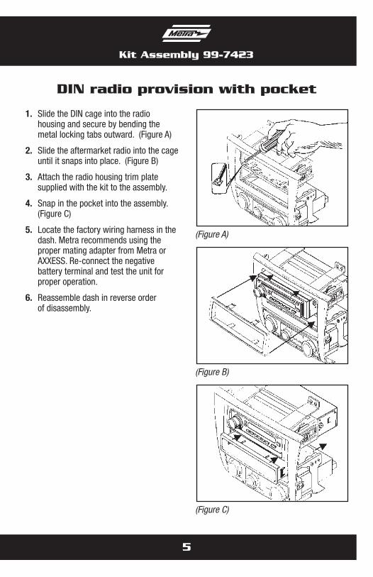
1. Slide the DIN cage into the radio housing and secure by bending the metal locking tabs outward. (Figure A)
2. Slide the aftermarket radio into the cage until it snaps into place. (Figure B)
3. Attach the radio housing trim plate supplied with the kit to the assembly.
4. Snap in the pocket into the assembly. (Figure C)
5. Locate the factory wiring harness in the dash. Metra recommends using the proper mating adapter from Metra or AXXESS. Re-connect the negative battery terminal and test the unit for proper operation.
6. Reassemble dash in reverse order of disassembly.
DIN radio provision with pocket
(Figure A)
(Figure C)
(Figure B)
Kit Assembly 99-7423
6
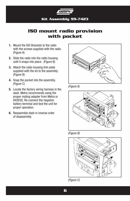
ISO mount radio provisionwith pocket
1. Mount the ISO Brackets to the radio with the screws supplied with the radio. (Figure A)
2. Slide the radio into the radio housing until it snaps into place. (Figure B)
3. Attach the radio housing trim plate supplied with the kit to the assembly. (Figure B)
4. Snap the pocket into the assembly. (Figure C)
5. Locate the factory wiring harness in the dash. Metra recommends using the proper mating adapter from Metra or AXXESS. Re-connect the negative battery terminal and test the unit for proper operation.
6. Reassemble dash in reverse order of disassembly.
(Figure A)
(Figure C)
(Figure B)
7
Kit Assembly 99-7423
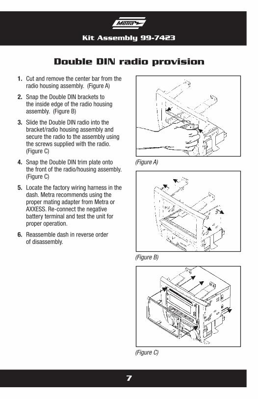
1. Cut and remove the center bar from the radio housing assembly. (Figure A)
2. Snap the Double DIN brackets to the inside edge of the radio housing assembly. (Figure B)
3. Slide the Double DIN radio into the bracket/radio housing assembly and secure the radio to the assembly using the screws supplied with the radio. (Figure C)
4. Snap the Double DIN trim plate onto the front of the radio/housing assembly. (Figure C)
5. Locate the factory wiring harness in the dash. Metra recommends using the proper mating adapter from Metra or AXXESS. Re-connect the negative battery terminal and test the unit for proper operation.
6. Reassemble dash in reverse order of disassembly.
Double DIN radio provision
(Figure A)
(Figure C)
(Figure B)
Kit Assembly 99-7423
8
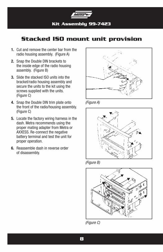
Stacked ISO mount unit provision
1. Cut and remove the center bar from the radio housing assembly. (Figure A)
2. Snap the Double DIN brackets to the inside edge of the radio housing assembly. (Figure B)
3. Slide the stacked ISO units into the bracket/radio housing assembly and secure the units to the kit using the screws supplied with the units. (Figure C)
4. Snap the Double DIN trim plate onto the front of the radio/housing assembly. (Figure C)
5. Locate the factory wiring harness in the dash. Metra recommends using the proper mating adapter from Metra or AXXESS. Re-connect the negative battery terminal and test the unit for proper operation.
6. Reassemble dash in reverse order of disassembly.
(Figure A)
(Figure C)
(Figure B)
Notes

Notes

Notes

METRA. THE WORLD’S BEST KITS.™
© COPYRIGHT 2004-2011 METRA ELECTRONICS CORPORATION 1-800-221-0932 metraonline.com
INSTALLATION INSTRUCTIONS FOR PART 99-7423
REV.
5/7
/12
METRA. THE WORLD’S BEST KITS.™
© COPYRIGHT 2004-2011 METRA ELECTRONICS CORPORATION
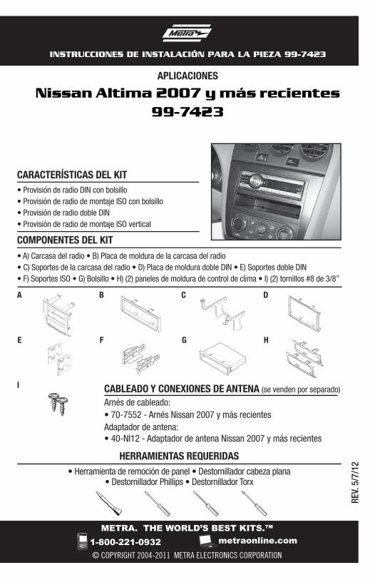
APLICACIONES
1-800-221-0932 metraonline.com
INSTRUCCIONES DE INSTALACIÓN PARA LA PIEZA 99-7423
REV.
5/7
/12
CABLEADO Y CONEXIONES DE ANTENA (se venden por separado)
Arnés de cableado:• 70-7552 - Arnés Nissan 2007 y más recientesAdaptador de antena:• 40-NI12 - Adaptador de antena Nissan 2007 y más recientes
• Herramienta de remoción de panel • Destornillador cabeza plana• Destornillador Phillips • Destornillador Torx
HERRAMIENTAS REQUERIDAS
Nissan Altima 2007 y más recientes99-7423
• A) Carcasa del radio • B) Placa de moldura de la carcasa del radio • C) Soportes de la carcasa del radio • D) Placa de moldura doble DIN • E) Soportes doble DIN • F) Soportes ISO • G) Bolsillo • H) (2) paneles de moldura de control de clima • I) (2) tornillos #8 de 3/8”
CARACTERÍSTICAS DEL KIT
COMPONENTES DEL KIT
B CA
• Provisión de radio DIN con bolsillo• Provisión de radio de montaje ISO con bolsillo• Provisión de radio doble DIN• Provisión de radio de montaje ISO vertical
D
I
F GE H
Indice
Desmontaje del tablero
– Nissan Altima 2007 y más recientes ................................................................................3
Ensamble del kit
– Preparación del kit ...........................................................................................................4
– Provisión de radio DIN con bolsillo ...................................................................................5
– Provisión de radio de montaje ISO con bolsillo .................................................................6
– Provisión de radio doble DIN ............................................................................................7
– Provisión de radio de montaje ISO vertical .......................................................................8
99-7423
PRECAUCIÓN: Metra recomienda desconectar el terminal negativo de la batería antes de comenzar cualquier instalación. Todos los accesorios, interruptores y, especialmente, las luces indicadoras de airbag deben estar enchufados antes de volver a conectar la batería o comenzar el ciclo de ignición.
Nota: Remítase a las instrucciones incluidas con el radio de posventa.
KNOWLEDGE IS POWEREnhance your installation and fabrication skills by enrolling in the most recognized and respected mobile electronics school in our industry.Log onto www.installerinstitute.com or call 800-354-6782 for more information and take steps toward a better tomorrow.
Metra recomienda técnicos con certificación del Programa de Certificación en Electrónica Móvil (Mobile Electronics Certification Program, MECP).
EL CONOCIMIENTO ES PODERMejore sus habilidades de instalación y fabricación inscribiéndose en la escuela de dispositivos electrónicos móviles más reconocida y respetada de nuestra industria. Regístrese en www.installerinstitute.com o llame al 800-354-6782 para obtener más información y avance hacia un futuro mejor.

1. Desenganche y quite el panel de la moldura entre la palanca de velocidades y el panel del radio/control de clima. (Figura A)
2. Quite los (2) tornillos Phillips que quedan a la vista detrás del panel que está debajo del panel del radio/control de clima. (Figura A)
3. Desenganche y quite el panel de la moldura del control de clima y quite (2) tornillos Phillips que quedan a la vista detrás del panel. (Figura B)
4. Desenganche, desconecte y quite todo el panel del radio/control del clima. (Figura B)
5. Quite los (5) tornillos T-20 Torx que sujetan los soportes del radio/control de clima y desenganche y quite el control de clima.
Nota: Conserve los controles de clima de fábrica para reutilizarlos durante el ensamble del kit.
Continuará la preparación del kit
3
Nissan Altima 2007 y más recientes
Desmontaje del tablero 99-7423
(Figura A)
(Figura C)
PASSAIR BAG
(Figura B)
4
Ensamble del kit 99-7423
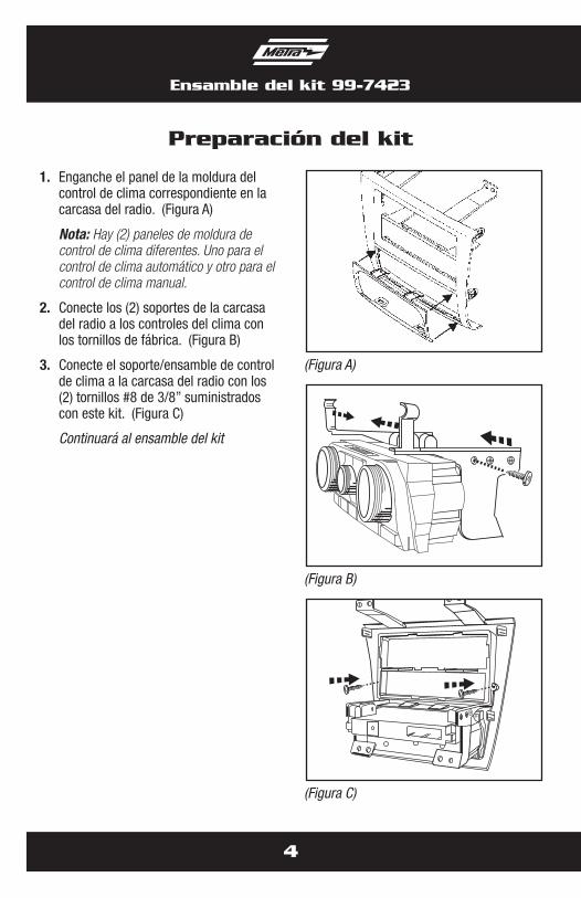
1. Enganche el panel de la moldura del control de clima correspondiente en la carcasa del radio. (Figura A)
Nota: Hay (2) paneles de moldura de control de clima diferentes. Uno para el control de clima automático y otro para el control de clima manual.
2. Conecte los (2) soportes de la carcasa del radio a los controles del clima con los tornillos de fábrica. (Figura B)
3. Conecte el soporte/ensamble de control de clima a la carcasa del radio con los (2) tornillos #8 de 3/8” suministrados con este kit. (Figura C)
Continuará al ensamble del kit
Preparación del kit
(Figura A)
(Figura C)
(Figura B)
5
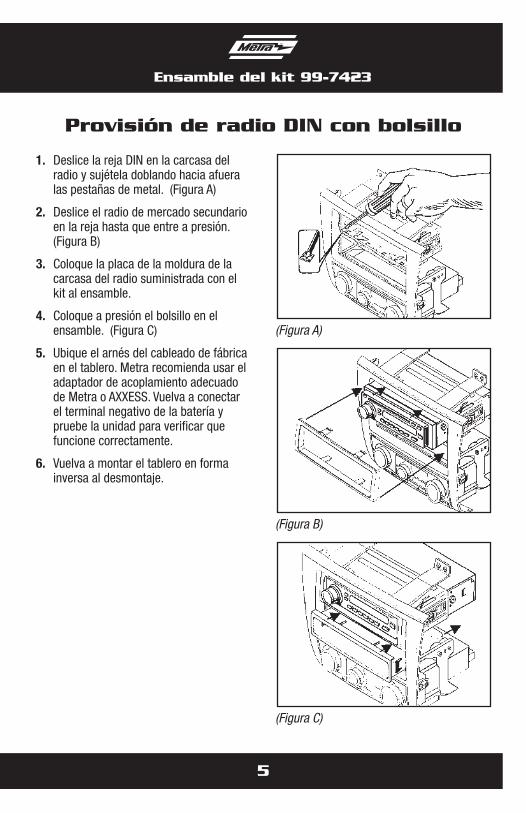
Ensamble del kit 99-7423
1. Deslice la reja DIN en la carcasa del radio y sujétela doblando hacia afuera las pestañas de metal. (Figura A)
2. Deslice el radio de mercado secundario en la reja hasta que entre a presión. (Figura B)
3. Coloque la placa de la moldura de la carcasa del radio suministrada con el kit al ensamble.
4. Coloque a presión el bolsillo en el ensamble. (Figura C)
5. Ubique el arnés del cableado de fábrica en el tablero. Metra recomienda usar el adaptador de acoplamiento adecuado de Metra o AXXESS. Vuelva a conectar el terminal negativo de la batería y pruebe la unidad para verificar que funcione correctamente.
6. Vuelva a montar el tablero en forma inversa al desmontaje.
Provisión de radio DIN con bolsillo
(Figura A)
(Figura C)
(Figura B)

Ensamble del kit 99-7423
6
Provisión de radio de montaje ISOcon bolsillo
1. Monte los soportes ISO en el radio con los tornillos que vienen con el radio.(Figura A)
2. Deslice el radio en la carcasa hasta que entre a presión. (Figura B)
3. Coloque la placa de la moldura de la carcasa del radio suministrada con el kit al ensamble. (Figura B)
4. Coloque a presión el bolsillo en el ensamble. (Figura C)
5. Ubique el arnés del cableado de fábrica en el tablero. Metra recomienda usar el adaptador de acoplamiento adecuado de Metra o AXXESS. Vuelva a conectar el terminal negativo de la batería y pruebe la unidad para verificar que funcione correctamente.
6. Vuelva a montar el tablero en forma inversa al desmontaje.
(Figura A)
(Figura C)
(Figura B)

7
Ensamble del kit 99-7423
1. Corte y quite la barra central del conjunto de la carcasa del radio. (Figura A)
2. Coloque a presión los soportes Doble DIN en el borde interior del conjunto de la carcasa del radio. (Figura B)
3. Deslice el radio doble DIN en el soporte/conjunto de la carcasa del radio y sujete el radio al conjunto utilizando los tornillos suministrados con el radio. (Figura C)
4. Coloque a presión la placa de la moldura doble DIN al frente del conjunto del radio/carcasa. (Figura C)
5. Ubique el arnés del cableado de fábrica en el tablero. Metra recomienda usar el adaptador de acoplamiento adecuado de Metra o AXXESS. Vuelva a conectar el terminal negativo de la batería y pruebe la unidad para verificar que funcione correctamente.
6. Vuelva a montar el tablero en forma inversa al desmontaje.
Provisión de radio doble DIN
(Figura A)
(Figura C)
(Figura B)

Ensamble del kit 99-7423
8
Provisión de radio de montajeISO vertical
1. Corte y quite la barra central del conjunto de la carcasa del radio. (Figura A)
2. Coloque a presión los soportes Doble DIN en el borde interior del conjunto de la carcasa del radio. (Figura B)
3. Deslice las unidades ISO verticales en el soporte/ensamble de alojamiento del radio y sujete las unidades al kit utilizando los tornillos suministrados con las unidades. (Figura C)
4. Coloque a presión la placa de la moldura doble DIN al frente del conjunto del radio/carcasa. (Figura C)
5. Ubique el arnés del cableado de fábrica en el tablero. Metra recomienda usar el adaptador de acoplamiento adecuado de Metra o AXXESS. Vuelva a conectar el terminal negativo de la batería y pruebe la unidad para verificar que funcione correctamente.
6. Vuelva a montar el tablero en forma inversa al desmontaje.
(Figura A)
(Figura C)
(Figura B)

Notas

Notas

Notas

METRA. THE WORLD’S BEST KITS.™
© COPYRIGHT 2004-2011 METRA ELECTRONICS CORPORATION 1-800-221-0932 metraonline.com
INSTRUCCIONES DE INSTALACIÓN PARA LA PIEZA 99-7423
REV.
5/7
/12