Embed Size (px)
Citation preview
MEP-7xxx Direct-Coupled Actuators (120 to 190 in-lb.) 1 Applications Guide, AN1113A Rev. B
Applications Guide
DRAFTNOTE: Watermark is
on nonwritable DRAFT
Watermark layer. Turn the
layer off or delete layer
to remove from the final
document.
MEP-7xxx
Direct-Coupled Actuators (120 to 320 in-lb.)
ContentsImportant Notices........................................................................................................................... 2
Introduction .................................................................................................................................... 2
Models ............................................................................................................................................ 3
Torque Requirements for Dampers ................................................................................................. 3
Accessories ..................................................................................................................................... 4
Master/Slave Wiring........................................................................................................................ 5
All Master/Slave Combinations .................................................................................................... 5
MEP-7802/7852 Proportional Actuators ...................................................................................... 5
MEP-7801/7803 Tri-State Actuators ............................................................................................. 6
MEP-7851/7853 Tri-State with Fail-Safe Actuators....................................................................... 6
Configuration .................................................................................................................................. 7
Direction, Feedback, and Auto-Mapping (Proportional MEP-7xx2 Models) ................................. 7
Fail-Safe Direction (MEP-7x5x) .................................................................................................... 8
Troubleshooting .............................................................................................................................. 8
Auxiliary Switch Does Not Work ................................................................................................. 8
Fail-Safe Does Not Work .............................................................................................................. 8
Feedback Does Not Work ............................................................................................................ 8
No Rotation ................................................................................................................................. 9
Rotation in Wrong Direction ....................................................................................................... 9
Stroke Range Is Wrong ................................................................................................................ 9
Wiring Issues ............................................................................................................................... 9
Index ............................................................................................................................................. 10Specifications, design, and operation are subject to change without notice.
MEP-7xxx Direct-Coupled Actuators (120 to 190 in-lb.) 2 Applications Guide, AN1113A Rev. B
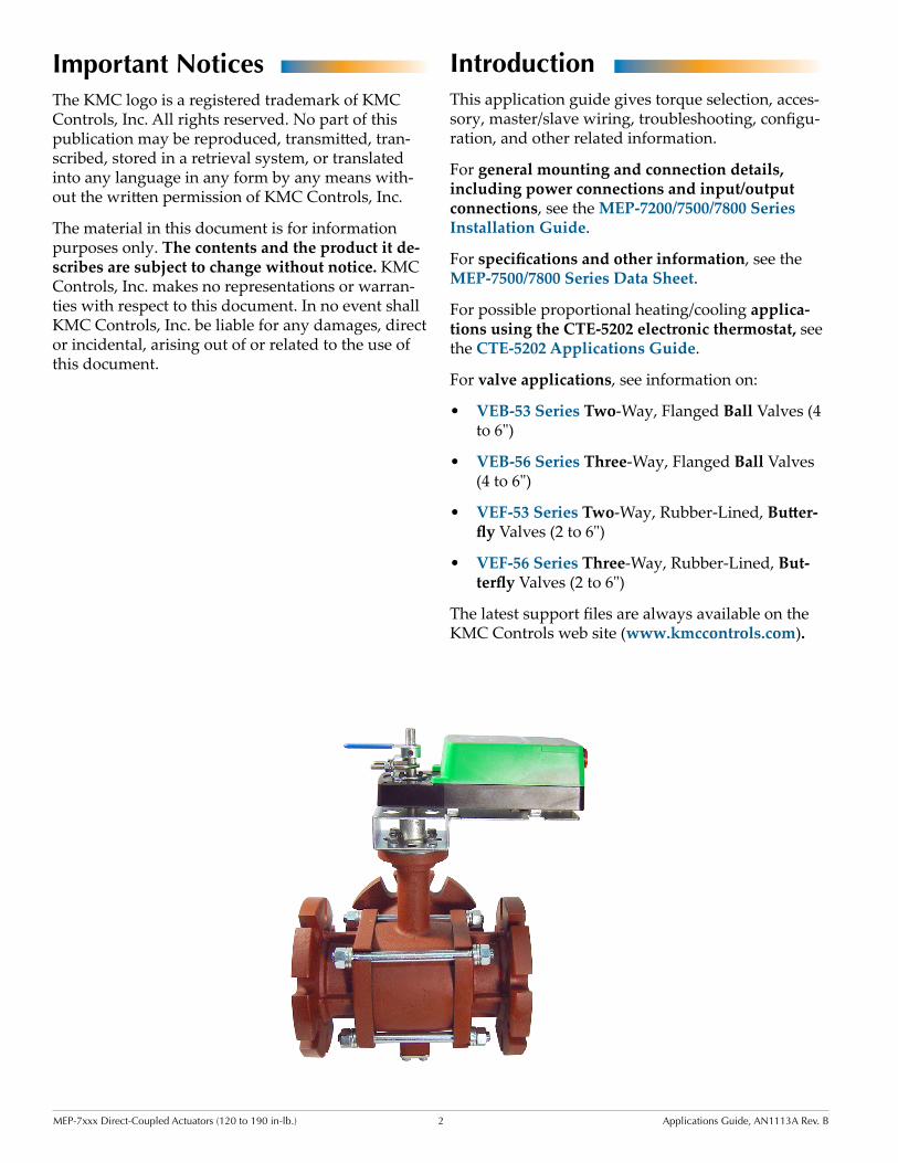
IntroductionThis application guide gives torque selection, acces-sory, master/slave wiring, troubleshooting, configu-ration, and other related information.
For general mounting and connection details, including power connections and input/output connections, see the MEP-7200/7500/7800 Series Installation Guide.
For specifications and other information, see the MEP-7500/7800 Series Data Sheet.
For possible proportional heating/cooling applica-tions using the CTE-5202 electronic thermostat, see the CTE-5202 Applications Guide.
For valve applications, see information on:
• VEB-53 Series Two-Way, Flanged Ball Valves (4 to 6")
• VEB-56 Series Three-Way, Flanged Ball Valves (4 to 6")
• VEF-53 Series Two-Way, Rubber-Lined, Butter-fly Valves (2 to 6")
• VEF-56 Series Three-Way, Rubber-Lined, But-terfly Valves (2 to 6")
The latest support files are always available on the KMC Controls web site (www.kmccontrols.com).
Important NoticesThe KMC logo is a registered trademark of KMC Controls, Inc. All rights reserved. No part of this publication may be reproduced, transmitted, tran-scribed, stored in a retrieval system, or translated into any language in any form by any means with-out the written permission of KMC Controls, Inc.
The material in this document is for information purposes only. The contents and the product it de-scribes are subject to change without notice. KMC Controls, Inc. makes no representations or warran-ties with respect to this document. In no event shall KMC Controls, Inc. be liable for any damages, direct or incidental, arising out of or related to the use of this document.
MEP-7xxx Direct-Coupled Actuators (120 to 190 in-lb.) 3 Applications Guide, AN1113A Rev. B
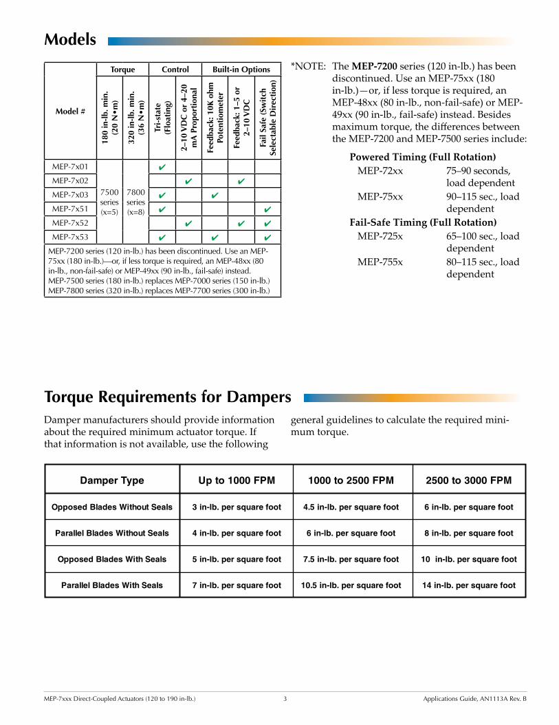
Torque Requirements for Dampers
Models
Powered Timing (Full Rotation)MEP-72xx 75–90 seconds,
load dependentMEP-75xx 90–115 sec., load
dependentFail-Safe Timing (Full Rotation)
MEP-725x 65–100 sec., load dependent
MEP-755x 80–115 sec., load dependent
Damper manufacturers should provide information about the required minimum actuator torque. If that information is not available, use the following
*NOTE: The MEP-7200 series (120 in-lb.) has been discontinued. Use an MEP-75xx (180 in-lb.)—or, if less torque is required, an MEP-48xx (80 in-lb., non-fail-safe) or MEP-49xx (90 in-lb., fail-safe) instead. Besides maximum torque, the differences between the MEP-7200 and MEP-7500 series include:
Damper Type
Opposed Blades Without Seals
Parallel Blades Without Seals
Opposed Blades With Seals
Parallel Blades With Seals
Up to 1000 FPM
3 in-lb. per square foot
4 in-lb. per square foot
5 in-lb. per square foot
7 in-lb. per square foot
1000 to 2500 FPM
4.5 in-lb. per square foot
6 in-lb. per square foot
7.5 in-lb. per square foot
10.5 in-lb. per square foot
2500 to 3000 FPM
6 in-lb. per square foot
8 in-lb. per square foot
10 in-lb. per square foot
14 in-lb. per square foot
general guidelines to calculate the required mini-mum torque.
Model #
Torque Control Built-in Options
180
in-l
b. m
in.
(20
N•
m)
320
in-l
b. m
in.
(36
N•
m)
Tri-
stat
e (F
loat
ing)
2–10
VD
C o
r 4–
20
mA
Pro
port
iona
l
Feed
back
: 10K
ohm
Po
tent
iom
eter
Feed
back
: 1–5
or
2–10
VD
C
Fail
Safe
(Sw
itch
Se
lect
able
Dir
ecti
on)
MEP-7x01
7500 series(x=5)
7800 series(x=8)
4
MEP-7x02 4 4
MEP-7x03 4 4
MEP-7x51 4 4
MEP-7x52 4 4 4
MEP-7x53 4 4 4
MEP-7200 series (120 in-lb.) has been discontinued. Use an MEP-75xx (180 in-lb.)—or, if less torque is required, an MEP-48xx (80 in-lb., non-fail-safe) or MEP-49xx (90 in-lb., fail-safe) instead.MEP-7500 series (180 in-lb.) replaces MEP-7000 series (150 in-lb.)MEP-7800 series (320 in-lb.) replaces MEP-7700 series (300 in-lb.)
MEP-7xxx Direct-Coupled Actuators (120 to 190 in-lb.) 4 Applications Guide, AN1113A Rev. B
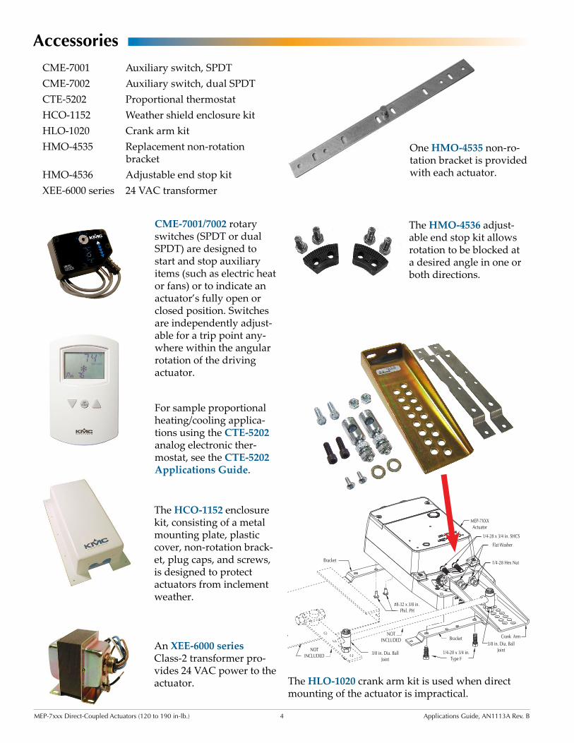
The HMO-4536 adjust-able end stop kit allows rotation to be blocked at a desired angle in one or both directions.
CME-7001/7002 rotary switches (SPDT or dual SPDT) are designed to start and stop auxiliary items (such as electric heat or fans) or to indicate an actuator’s fully open or closed position. Switches are independently adjust-able for a trip point any-where within the angular rotation of the driving actuator.
AccessoriesCME-7001 Auxiliary switch, SPDTCME-7002 Auxiliary switch, dual SPDTCTE-5202 Proportional thermostatHCO-1152 Weather shield enclosure kitHLO-1020 Crank arm kitHMO-4535 Replacement non-rotation
bracketHMO-4536 Adjustable end stop kitXEE-6000 series 24 VAC transformer
The HCO-1152 enclosure kit, consisting of a metal mounting plate, plastic cover, non-rotation brack-et, plug caps, and screws, is designed to protect actuators from inclement weather.
For sample proportional heating/cooling applica-tions using the CTE-5202 analog electronic ther-mostat, see the CTE-5202 Applications Guide.
The HLO-1020 crank arm kit is used when direct mounting of the actuator is impractical.
One HMO-4535 non-ro-tation bracket is provided with each actuator.
An XEE-6000 series Class-2 transformer pro-vides 24 VAC power to the actuator.
MEP-7xxx Direct-Coupled Actuators (120 to 190 in-lb.) 5 Applications Guide, AN1113A Rev. B
Master/Slave WiringAll Master/Slave Combinations1. Follow the instructions in the Wiring (General)
section of the MEP-7200/7500/7800 Series Installation Guide and also include the following steps.
2. Connect the actuators according to the relevant illustration below.
4. Check that the wiring is properly phased (“~” to “~” and “ ” to “ ”). In tri-state actuators, CW and CWW are connected to like terminals for “stacked-mounted” applications and opposite terminals for “opposite-mounted” applications.
2. On applicable models, set the Master and the Slave’s CW/CCW switches according to the relevant illustration and chart.
24 VAC/VDCPower In
(MEP
-7x5
2 On
ly)
4–20 mA Control Signal
1–5 or 2–10 VDC Feedback Signal
Control Signal Common
(MEP
-7x5
2 On
ly)
MASTER SLAVE
(MEP-7802/7852 Opposite Mount, 4–20 mA Input)
MASTER
24 VAC/VDCPower In
(MEP
-7x5
2 On
ly)
4–20 mA Control Signal
1–5 or 2–10 VDC Feedback Signal
Control Signal Common
(MEP
-7x5
2 On
ly)
MASTER SLAVE
(MEP-7802/7852 Stacked Mount, 4–20 mA Input)
MASTER
3. On applicable models, set the Master and the Slave’s FAIL switches according to the relevant illustration and chart.
5. If using feedback, connect to one actuator only. Do NOT interconnect the feedback between the master and slave.
NOTE: The 4–20 mA input and auto-mapping options are not available with Master/Slave actuators.
CAUTIONMiswiring or wrong switch positions could result in damage to one or more actuators. Carefully check wiring and switch positions.
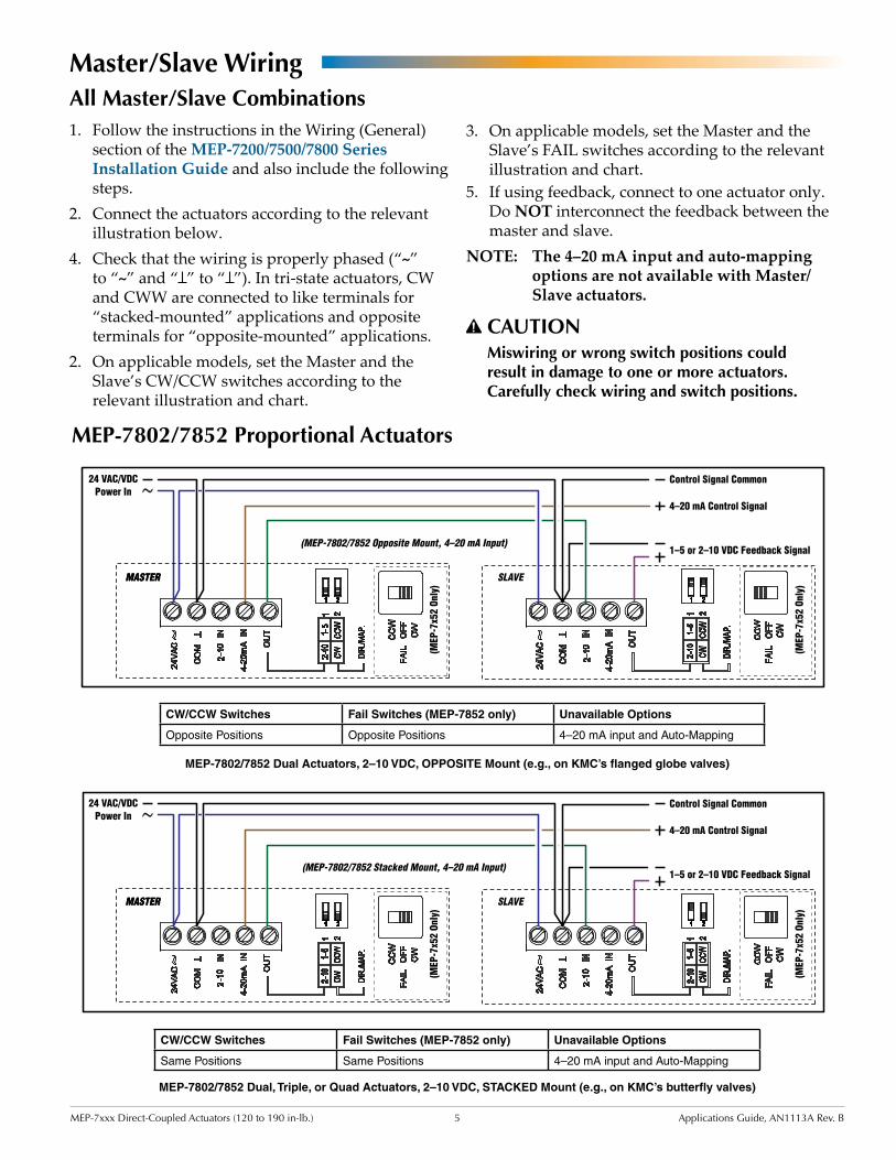
MEP-7802/7852 Dual Actuators, 2–10 VDC, OPPOSITE Mount (e.g., on KMC’s flanged globe valves)
CW/CCW Switches Fail Switches (MEP-7852 only) Unavailable Options
Opposite Positions Opposite Positions 4–20 mA input and Auto-Mapping
MEP-7802/7852 Proportional Actuators
24 VAC/VDCPower In
(MEP
-7x5
2 On
ly)
4–20 mA Control Signal
1–5 or 2–10 VDC Feedback Signal
Control Signal Common
(MEP
-7x5
2 On
ly)
MASTER SLAVE
(MEP-7802/7852 Opposite Mount, 4–20 mA Input)
MASTER
24 VAC/VDCPower In
(MEP
-7x5
2 On
ly)
4–20 mA Control Signal
1–5 or 2–10 VDC Feedback Signal
Control Signal Common(M
EP-7
x52
Only
)
MASTER SLAVE
(MEP-7802/7852 Stacked Mount, 4–20 mA Input)
MASTER
MEP-7802/7852 Dual, Triple, or Quad Actuators, 2–10 VDC, STACKED Mount (e.g., on KMC’s butterfly valves)
CW/CCW Switches Fail Switches (MEP-7852 only) Unavailable Options
Same Positions Same Positions 4–20 mA input and Auto-Mapping
MEP-7xxx Direct-Coupled Actuators (120 to 190 in-lb.) 6 Applications Guide, AN1113A Rev. B
24 VAC/VDCPower In
(MEP
-7x5
2 On
ly)
0–10 VDC Control Signal
0–5 or 0–10 VDC Feedback Signal
Control Signal Common
(MEP
-7x5
2 On
ly)
24 VAC/VDCPower In
CWCCW
SLAVEMASTER
MASTER SLAVE
(MEP-7802/7852 Opposite Mount, 0–10 VDC Input)
(MEP-7802/7852 Stacked Mount, 0–10 VDC Input)
(MEP-7851/7853 Opposite Mount)
(MEP-7801/7803 Stacked Mount)
(MEP-7801/7803 Opposite Mount)
(MEP-7851/7853 Stacked Mount)
24 VAC/VDCPower In
(MEP
-7x5
2 On
ly)
0–10 VDC Control Signal
0–5 or 0–10 VDC Feedback Signal
Control Signal Common
(MEP
-7x5
2 On
ly)
MASTER SLAVE
24 VAC/VDCPower In
CW CCW
SLAVEMASTER
24 VAC/VDCPower In
CWCCW
SLAVEMASTER
24 VAC/VDCPower In
CW CCW
SLAVEMASTER
MASTER
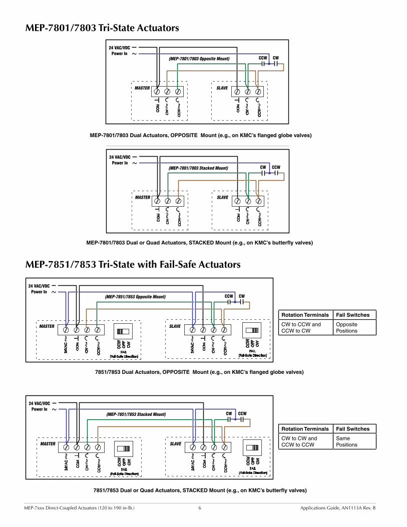
7851/7853 Dual Actuators, OPPOSITE Mount (e.g., on KMC’s flanged globe valves)
MEP-7851/7853 Tri-State with Fail-Safe Actuators
24 VAC/VDCPower In
(MEP
-7x5
2 On
ly)
0–10 VDC Control Signal
0–5 or 0–10 VDC Feedback Signal
Control Signal Common
(MEP
-7x5
2 On
ly)
24 VAC/VDCPower In
CWCCW
SLAVEMASTER
MASTER SLAVE
(MEP-7802/7852 Opposite Mount, 0–10 VDC Input)
(MEP-7802/7852 Stacked Mount, 0–10 VDC Input)
(MEP-7851/7853 Opposite Mount)
(MEP-7801/7803 Stacked Mount)
(MEP-7801/7803 Opposite Mount)
(MEP-7851/7853 Stacked Mount)
24 VAC/VDCPower In
(MEP
-7x5
2 On
ly)
0–10 VDC Control Signal
0–5 or 0–10 VDC Feedback Signal
Control Signal Common
(MEP
-7x5
2 On
ly)
MASTER SLAVE
24 VAC/VDCPower In
CW CCW
SLAVEMASTER
24 VAC/VDCPower In
CWCCW
SLAVEMASTER
24 VAC/VDCPower In
CW CCW
SLAVEMASTER
MASTER
7851/7853 Dual or Quad Actuators, STACKED Mount (e.g., on KMC’s butterfly valves)
24 VAC/VDCPower In
(MEP
-7x5
2 On
ly)
0–10 VDC Control Signal
0–5 or 0–10 VDC Feedback Signal
Control Signal Common
(MEP
-7x5
2 On
ly)
24 VAC/VDCPower In
CWCCW
SLAVEMASTER
MASTER SLAVE
(MEP-7802/7852 Opposite Mount, 0–10 VDC Input)
(MEP-7802/7852 Stacked Mount, 0–10 VDC Input)
(MEP-7851/7853 Opposite Mount)
(MEP-7801/7803 Stacked Mount)
(MEP-7801/7803 Opposite Mount)
(MEP-7851/7853 Stacked Mount)
24 VAC/VDCPower In
(MEP
-7x5
2 On
ly)
0–10 VDC Control Signal
0–5 or 0–10 VDC Feedback Signal
Control Signal Common
(MEP
-7x5
2 On
ly)
MASTER SLAVE
24 VAC/VDCPower In
CW CCW
SLAVEMASTER
24 VAC/VDCPower In
CWCCW
SLAVEMASTER
24 VAC/VDCPower In
CW CCW
SLAVEMASTER
MASTER
MEP-7801/7803 Dual Actuators, OPPOSITE Mount (e.g., on KMC’s flanged globe valves)
MEP-7801/7803 Tri-State Actuators
24 VAC/VDCPower In
(MEP
-7x5
2 On
ly)
0–10 VDC Control Signal
0–5 or 0–10 VDC Feedback Signal
Control Signal Common
(MEP
-7x5
2 On
ly)
24 VAC/VDCPower In
CWCCW
SLAVEMASTER
MASTER SLAVE
(MEP-7802/7852 Opposite Mount, 0–10 VDC Input)
(MEP-7802/7852 Stacked Mount, 0–10 VDC Input)
(MEP-7851/7853 Opposite Mount)
(MEP-7801/7803 Stacked Mount)
(MEP-7801/7803 Opposite Mount)
(MEP-7851/7853 Stacked Mount)
24 VAC/VDCPower In
(MEP
-7x5
2 On
ly)
0–10 VDC Control Signal
0–5 or 0–10 VDC Feedback Signal
Control Signal Common
(MEP
-7x5
2 On
ly)
MASTER SLAVE
24 VAC/VDCPower In
CW CCW
SLAVEMASTER
24 VAC/VDCPower In
CWCCW
SLAVEMASTER
24 VAC/VDCPower In
CW CCW
SLAVEMASTER
MASTER
MEP-7801/7803 Dual or Quad Actuators, STACKED Mount (e.g., on KMC’s butterfly valves)
Rotation Terminals Fail Switches
CW to CCW and CCW to CW
Opposite Positions
Rotation Terminals Fail Switches
CW to CW and CCW to CCW
Same Positions
MEP-7xxx Direct-Coupled Actuators (120 to 190 in-lb.) 7 Applications Guide, AN1113A Rev. B
Configuration
Direction, Feedback, and Auto-Mapping (Proportional MEP-7xx2 Models)
MEP-7xx2 models also offer a actuator/signal range reset program (auto-mapping) feature that reassigns the full 2–10 VDC input signal scale over a reduced stroke range for more precise control.
NOTE: The auto-mapping feature works best for ranges that are more than about 45°.
NOTE: Auto-mapping scales the input signal and feedback voltage over the selected mechanical rotation range. For example, if the maximum auto-mapping rotation is set for 75°, then at 100% of the signal input (10 VDC), the actuator will rotate to and stop at 75° and the feedback signal will then be 100% of the selected voltage range (either 5 or 10 VDC).
To set the auto-mapping:1. Use the HMO-4536 adjustable end stop kit to
limit the stroke of the actuator as needed.2. With power applied to the actuator, flip selector
switch #2 (from its required CW or CCW increasing voltage direction) to start the reset mode. The actuator will first move to the CCW limit. The complete reset process will take approximately four minutes.
NOTE: On fail-safe models, wait for at least one minute after power has been applied to the actuator (allowing the capacitors to fully charge) before initiating the automap feature.
3. Return selector switch #2 to the required increasing voltage direction before the reset finishes. The reset process is complete after the actuator has moved to the CW limit and has begun to position normally.
4. Verify that the actuator travels completely across the new range.
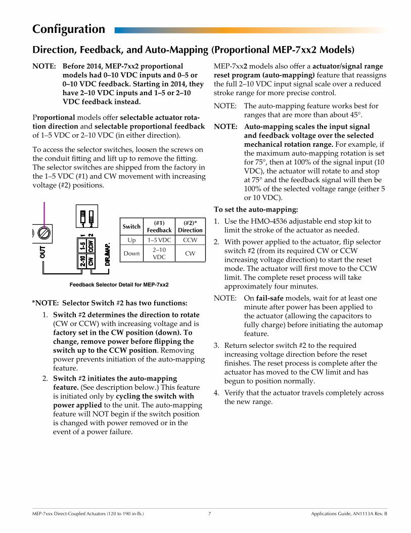
Proportional models offer selectable actuator rota-tion direction and selectable proportional feedback of 1–5 VDC or 2–10 VDC (in either direction).
To access the selector switches, loosen the screws on the conduit fitting and lift up to remove the fitting. The selector switches are shipped from the factory in the 1–5 VDC (#1) and CW movement with increasing voltage (#2) positions.
*NOTE: Selector Switch #2 has two functions:1. Switch #2 determines the direction to rotate
(CW or CCW) with increasing voltage and is factory set in the CW position (down). To change, remove power before flipping the switch up to the CCW position. Removing power prevents initiation of the auto-mapping feature.
2. Switch #2 initiates the auto-mapping feature. (See description below.) This feature is initiated only by cycling the switch with power applied to the unit. The auto-mapping feature will NOT begin if the switch position is changed with power removed or in the event of a power failure.
Switch(#1)
Feedback(#2)*
Direction
Up 1–5 VDC CCW
Down2–10 VDC
CW
NOTE: Before 2014, MEP-7xx2 proportional models had 0–10 VDC inputs and 0–5 or 0–10 VDC feedback. Starting in 2014, they have 2–10 VDC inputs and 1–5 or 2–10 VDC feedback instead.
Feedback Selector Detail for MEP-7xx2
24 VAC/VDCPower In
Feedback Potentiometer
(MEP-7xx3 only)
24 VAC/VDCPower In
24 VAC/VDCPower In 2–10 VDC Control Signal
4–20 mA Control Signal
1–5 or 2–10 VDC Feedback Signal
Control Signal Common(M
EP-7
x52
Only
)
24 VAC/VDCPower In
21
Switch/Contact Jumper
Feedback Potentiometer
(MEP-7xx3 only)
Feedback Potentiometer
(MEP-7xx3 only)
CW
CCW
CW
CCW
1 2
MEP-7xxx Direct-Coupled Actuators (120 to 190 in-lb.) 8 Applications Guide, AN1113A Rev. B
Troubleshooting
Auxiliary Switch Does Not Work• Check the auxiliary switch setting. See the
CME-7001/7002 Auxiliary Switches Installation Guide.
• Check the wiring. See Wiring Issues on page 9.
Fail-Safe Does Not Work• After initial connection or reconnection to power,
proper fail-safe operation might be delayed up to 20 seconds for the MEP-725x/755x or up to 40 seconds for the MEP-785x (until the capacitors are fully charged).
• Check the Fail-Safe Direction switch. See Fail-Safe Direction (MEP-7x5x) on page 8.
Feedback Does Not WorkNOTE: Before 2014, MEP-7xx2 models had 0–5 or
0–10 VDC feedback. Starting in 2014, they have 1–5 or 2–10 VDC feedback. When replacing an older style actuator with a new actuator, configure the connected controller feedback input to match.
• Check the feedback switch setting. See Direction, Feedback, and Auto-Mapping (Proportional MEP-7xx2 Models) on page 7.
• Check the wiring. See Wiring Issues on page 9.
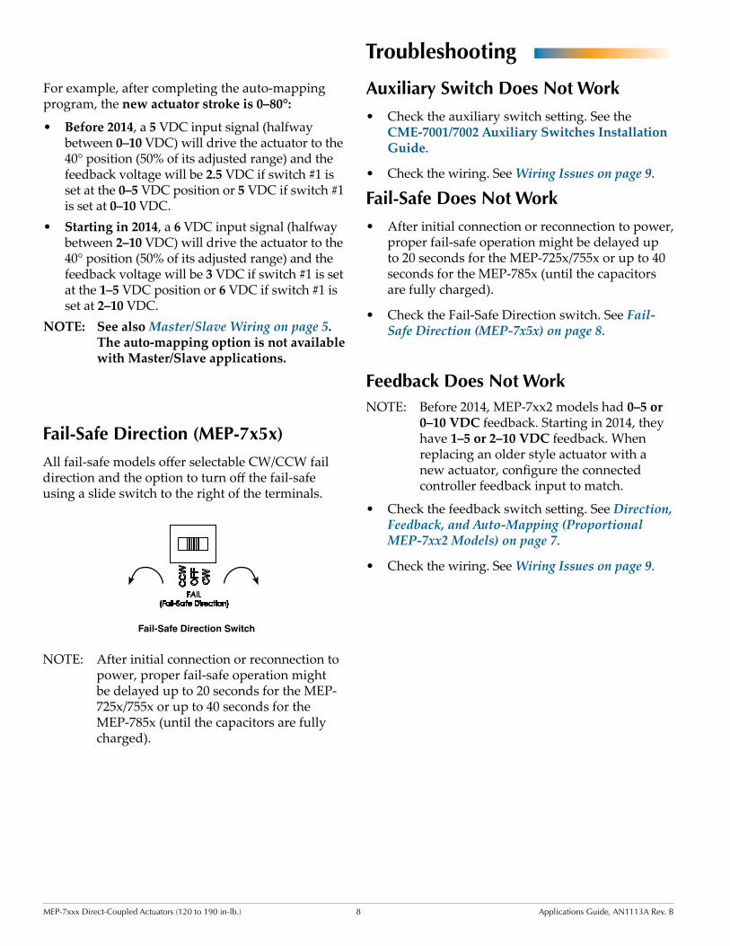
Fail-Safe Direction Switch
Fail-Safe Direction (MEP-7x5x)All fail-safe models offer selectable CW/CCW fail direction and the option to turn off the fail-safe using a slide switch to the right of the terminals.
NOTE: After initial connection or reconnection to power, proper fail-safe operation might be delayed up to 20 seconds for the MEP-725x/755x or up to 40 seconds for the MEP-785x (until the capacitors are fully charged).
24 VAC/VDCPower In
Feedback Potentiometer
(MEP-7xx3 only)
24 VAC/VDCPower In
24 VAC/VDCPower In 2–10 VDC Control Signal
4–20 mA Control Signal
1–5 or 2–10 VDC Feedback Signal
Control Signal Common
(MEP
-7x5
2 On
ly)
24 VAC/VDCPower In
21
Switch/Contact Jumper
Feedback Potentiometer
(MEP-7xx3 only)
Feedback Potentiometer
(MEP-7xx3 only)
CW
CCW
CW
CCW
1 2
For example, after completing the auto-mapping program, the new actuator stroke is 0–80°:
• Before 2014, a 5 VDC input signal (halfway between 0–10 VDC) will drive the actuator to the 40° position (50% of its adjusted range) and the feedback voltage will be 2.5 VDC if switch #1 is set at the 0–5 VDC position or 5 VDC if switch #1 is set at 0–10 VDC.
• Starting in 2014, a 6 VDC input signal (halfway between 2–10 VDC) will drive the actuator to the 40° position (50% of its adjusted range) and the feedback voltage will be 3 VDC if switch #1 is set at the 1–5 VDC position or 6 VDC if switch #1 is set at 2–10 VDC.
NOTE: See also Master/Slave Wiring on page 5. The auto-mapping option is not available with Master/Slave applications.
MEP-7xxx Direct-Coupled Actuators (120 to 190 in-lb.) 9 Applications Guide, AN1113A Rev. B
No RotationNOTE: Before 2014, MEP-7xx2 models had 0–10
VDC inputs. Starting in 2014, they have 2–10 VDC inputs. When replacing an older 0–10 VDC actuator with a 2–10 VDC actuator, configure the connected controller or thermostat output to match.
• Check that the direction switch (Switch 2) is fully engaged in the proper position. See Direction, Feedback, and Auto-Mapping (Proportional MEP-7xx2 Models) on page 7.
• Check that the shaft moves freely. (Press and hold the gear disengagement lever and manually rotate the shaft.)
• Check for a tripped circuit breaker to the trans-former (or power supply).
• Check polarity and strength of input signal.
• Check for proper supply voltage from the trans-former (or power supply) and that it has enough capacity (VA) for all connected devices. See their respective data sheets and Tips for Connecting 24-Volt Power Application Note (AN0604D).
• Check the wiring. See Wiring Issues on page 9.
Rotation in Wrong Direction• For tri-state models, check the CW/CCW wiring.
• For proportional models, check the position of the direction switch (Switch 2). See Direction, Feedback, and Auto-Mapping (Proportional MEP-7xx2 Models) on page 7.
• For fail-safe operation, check the Fail-Safe Direc-tion switch. See Fail-Safe Direction (MEP-7x5x) on page 8.
Stroke Range Is WrongNOTE: Before 2014, MEP-7xx2 models had 0–10
VDC inputs. Starting in 2014, they have 2–10 VDC inputs. When replacing an older 0–10 VDC actuator with a 2–10 VDC actuator, configure the connected controller output to match.
• Use and/or check position of the HMO-4536 adjustable end stop kit.
• Check the automapping. See Direction, Feed-back, and Auto-Mapping (Proportional MEP-7xx2 Models) on page 7.
• Check the voltage from the controller or thermo-stat.
Wiring Issues• For master/slave wiring, see Master/Slave Wir-
ing on page 5.
• Check for correct wiring for the application.
• Check the wiring at the connected devices.
• Use a voltmeter and ohmmeter to check the terminals for expected values.
• See Tips for Connecting 24-Volt Power Applica-tion Note (AN0604D).
NOTE: Wiring must be adequate to avoid exces-sive voltage drop on long runs! Allow plenty of “cushion” in measurements. A meter may be too slow to register tran-sient dips or peaks during startup.
MEP-7xxx Direct-Coupled Actuators (120 to 190 in-lb.) 10 Applications Guide, AN1113A Rev. B
Index
Symbols
0-5/0-10 vs. 1-5/2-10 VDC Feedback: 7, 80-10 vs. 2-10 VDC Inputs: 7, 8, 9
A
Accessories: 4Auto-Mapping: 7Auxiliary Switch: 4, 8
B
Bracket, Non-Rotation: 4
C
CME-7001/7002: 4Configuration: 7Crank Arm Kit: 4CTE-5202 Thermostat: 4
D
Dampers: 3Direction: 7, 9
E
Enclosure: 4
F
Fail-Safe: 8, 9Feedback: 7, 8
H
HCO-1152 Weather Shield Kit: 4HLO-1020 Crank Arm Kit: 4HMO-4535 Non-Rotation Bracket: 4HMO-4536 Adj. End Stop Kit: 4
I
Important Notices: 2Inputs: 7, 9
M
Master/Slave Wiring: 5MEP-7x5x: 8MEP-7xx2: 7MEP-72xx: 3MEP-7801/7803: 6MEP-7802/7852: 5MEP-7851/7853: 6Models: 3
© 2014 KMC Controls, Inc. AN1113A Rev. B
KMC Controls19476 Industrial DriveNew Paris, IN 46553
574.831.5250; Fax [email protected]
N
Non-Rotation Bracket: 4
P
Proportional: 5, 7, 8, 9
R
Range, Stroke: 7, 9Rotation: 7, 9
S
Stop Kit, End: 4Stroke Range: 8, 9Support Files: 2Switch
Auxiliary: 8Fail-Safe Direction: 8, 9Feedback Voltage: 7, 8Rotation Direction: 7, 9
T
Thermostat: 4Torque Selection: 3Transformer: 4Tri-State: 6, 9Troubleshooting: 8
V
Valve Applications: 2VEB-5x Series Ball Valves: 2VEF-5x Series Butterfly Valves: 2
W
Weather Shield Enclosure Kit: 4Web Site: 2Wiring: 5, 9
X
XEE-6000 Series: 4