Embed Size (px)
Citation preview

® ®
Active Around the World Probes and Measurement Fixtures
The Institute for Electronics and Measurement Technology
HELMUT FISCHER in Sindelfingen/Germany is
an innovative leader in the field of coatingthickness measure-
ment, material analysis, microhard-
ness testing, electricalconductivity- and
ferrite contentmeasurement as well
as for density and porosity testing.
The company is able torecommend the best solution for any appli-
cation. A compre-hensive range of
products is offered using X-ray fluores-cence; Beta-backscatter; Magnetic;Magnetic induction; Electric resistance; Eddy current and Coulometrictechniques. HELMUT FISCHER has 12 subsidiary
companies and 32 marketing agencies
strategically located around the globe.
FISCHERSCOPE® X-RAY to measure coatingthickness using the X-Ray fluorescence method.
The high quality standard of FISCHERinstruments is the result of our efforts toprovide the very best instrumentation toour customers.
FISCHER is a reliable and competentpartner, offering expert advice, extensiveservice, and training seminars.
Today, FISCHER instruments are usedsuccessfully in all technological fields ofindustry and research.
POROSCOPE® HV20 to test for pores and pinholesin nonconductive coatings.
Microhardness testing system FISCHERSCOPE® H100C.
Fischer Instrumentation (G.B.) Ltd.Lymington/Hampshire SO41 8JD, EnglandTel. (+44) 1590-683663, Fax (+44) 1590-684110Internet: http://www.fischergb.co.uk
Fischer Instruments, S.A.08018 Barcelona, SpainTel. (+34) 93 309 79 16, Fax (+34) 93 485 05 94E-Mail: [email protected]
Helmut Fischer Meettechniek B.V.5627 GB Eindhoven, The NetherlandsTel. (+31) 40 248 22 55, Fax (+31) 40 242 88 85E-Mail: [email protected]
Fischer Instruments K.K.Saitama-ken 340, JapanTel. (+81) 489 32 3621, Fax (+81) 489 32 3618E-Mail: [email protected]
Fischer Instrumentation (Far East) Ltd.Kwai Chung, N.T., Hong KongTel. (+852) 24 20 11 00, Fax (+852) 24 87 02 18E-Mail: [email protected]
Fischer Technology, Inc.Windsor, Ct. 06095, USATel. 860 683-0781, Fax 860 688-8496Internet: http://www.fischer-technology.com
Fischer Instrumentation (S) Pte Ltd.Singapore 118529, SingaporeTel. (+65) 276 67 76, Fax (+65) 276 76 67E-Mail: [email protected] Fischer Instrumentation Ltd.Shanghai 200437, P.R.C., ChinaTel. (+86) 21 6555 7455, Fax (+86) 21 6555 2441E-Mail: [email protected]
ISO 9001SQS RegistrationNo. 11899
Valid for Helmut Fischer AG and Branch Offices
Helmut Fischer GmbH+Co.KG71069 Sindelfingen, GermanyTel. (+49) 70 31 303-0, Fax (+49) 70 31 303-79Internet: http://www.Helmut-Fischer.com
Sole Agent for Helmut Fischer GmbH+Co.KG, Germany:
Helmut Fischer Elektronik und Messtechnik AGCH-6331 Hünenberg, SwitzerlandTel. (+41) 41 785 08 00, Fax (+41) 41 785 08 01E-Mail: [email protected]
Branch Offices of Helmut Fischer AG, Switzerland:
Fischer Instrumentation Electronique78180 Montigny le Bretonneux, FranceTel. (+33) (0) 1 30 58 00 58, Fax (+33) (0) 1 30 58 89 50E-Mail: [email protected]
Helmut Fischer S.R.L., Tecnica di Misura20128 Milano, ItalyTel. (+39) 02 255 26 26, Fax (+39) 02 257 00 39E-Mail: [email protected]
© Helmut Fischer GmbH+Co.KG Subjects to changes 902-052 Printed in Germany 03/02
01/0
1
Application Specific Probes The key to successful coating measurement
Probes are the most important compo-nent of systems used to measure coa-ting thickness with either magnetic, magnetic induction and eddy currentmethods. This is the reason significantefforts and resources are expended byFISCHER for the development and qua-lity control of probes.
• FISCHER probes are adapted and optimized for the application!This guarantees accurate and reliablemeasurement results.
• FISCHER probes are dependable and durable!The probes are long lasting and durable, even when measurements are to be per-formed which test their “wear resistance”.
• FISCHER probes are reliable!This is due to their advanced design, their careful assembly and use of high quality components.
Measurement Accuracy(DIN 55350 section 13, paragraph 2.1.1)The measurement accuracy has beendetermined with plastic foils of specificthickness. The specified value us cor-responds to the measured systematic de-viation (bias) between the measured thick-ness value and true thickness value of thecalibration foil.Example: 50 - 1000 µm: 0.5%
∆ usThis parameter is a quality indicator show-ing how good the measurement signal fromthe probe has been converted over thecharacteristic probe output function storedin the memory of the probe into a corres-ponding coating thickness value.
Measuring Methods and Processing Measuring Signals Technical Data and Selection of Probes
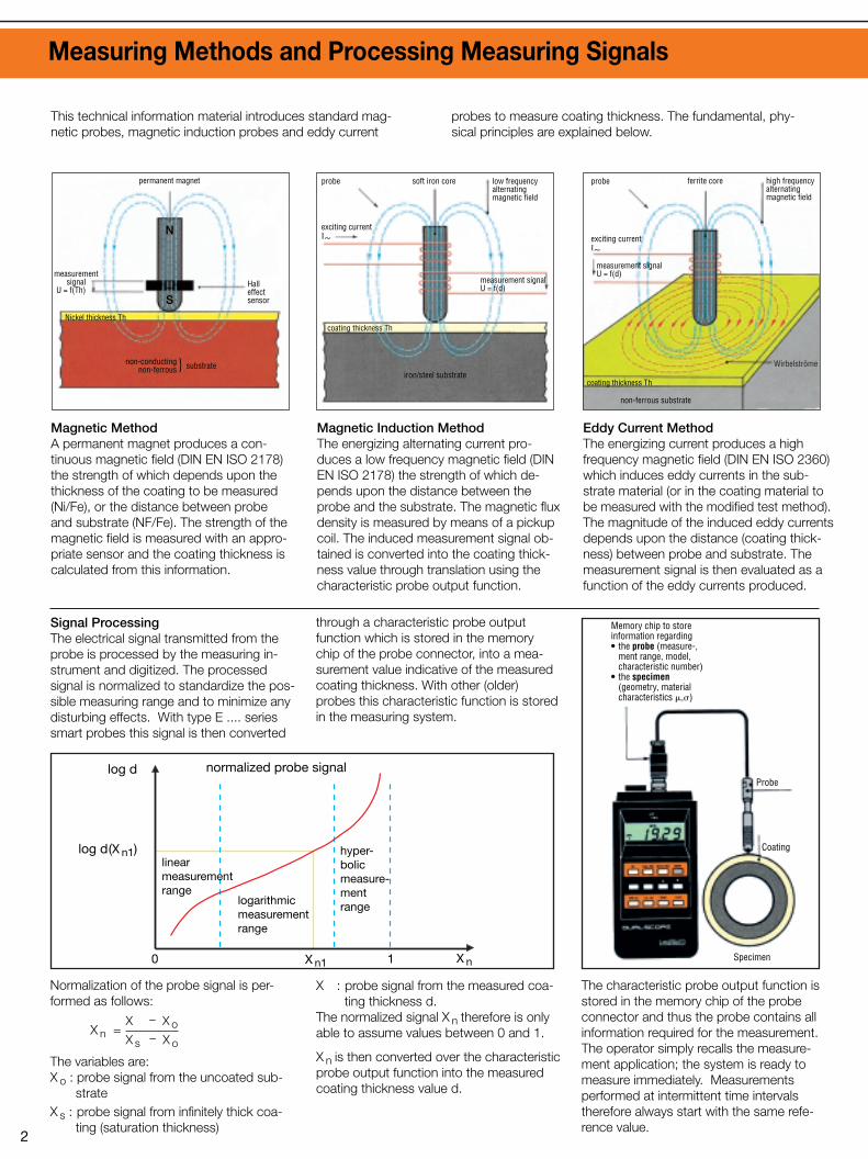
Magnetic MethodA permanent magnet produces a con-tinuous magnetic field (DIN EN ISO 2178)the strength of which depends upon thethickness of the coating to be measured(Ni/Fe), or the distance between probeand substrate (NF/Fe). The strength of themagnetic field is measured with an appro-priate sensor and the coating thickness iscalculated from this information.
Signal ProcessingThe electrical signal transmitted from theprobe is processed by the measuring in-strument and digitized. The processedsignal is normalized to standardize the pos-sible measuring range and to minimize anydisturbing effects. With type E .... seriessmart probes this signal is then converted
through a characteristic probe outputfunction which is stored in the memory chip of the probe connector, into a mea-surement value indicative of the measuredcoating thickness. With other (older)probes this characteristic function is storedin the measuring system.
Normalization of the probe signal is per-formed as follows:
X n =
The variables are:X o : probe signal from the uncoated sub-
strateX s : probe signal from infinitely thick coa-
ting (saturation thickness)
X : probe signal from the measured coa-ting thickness d.
The normalized signal X n therefore is onlyable to assume values between 0 and 1.
X n is then converted over the characteristicprobe output function into the measuredcoating thickness value d.
X – X oX s – X o
Magnetic Induction MethodThe energizing alternating current pro-duces a low frequency magnetic field (DINEN ISO 2178) the strength of which de-pends upon the distance between theprobe and the substrate. The magnetic fluxdensity is measured by means of a pickupcoil. The induced measurement signal ob-tained is converted into the coating thick-ness value through translation using thecharacteristic probe output function.
Eddy Current MethodThe energizing current produces a highfrequency magnetic field (DIN EN ISO 2360)which induces eddy currents in the sub-strate material (or in the coating material tobe measured with the modified test method).The magnitude of the induced eddy currentsdepends upon the distance (coating thick-ness) between probe and substrate. Themeasurement signal is then evaluated as afunction of the eddy currents produced.
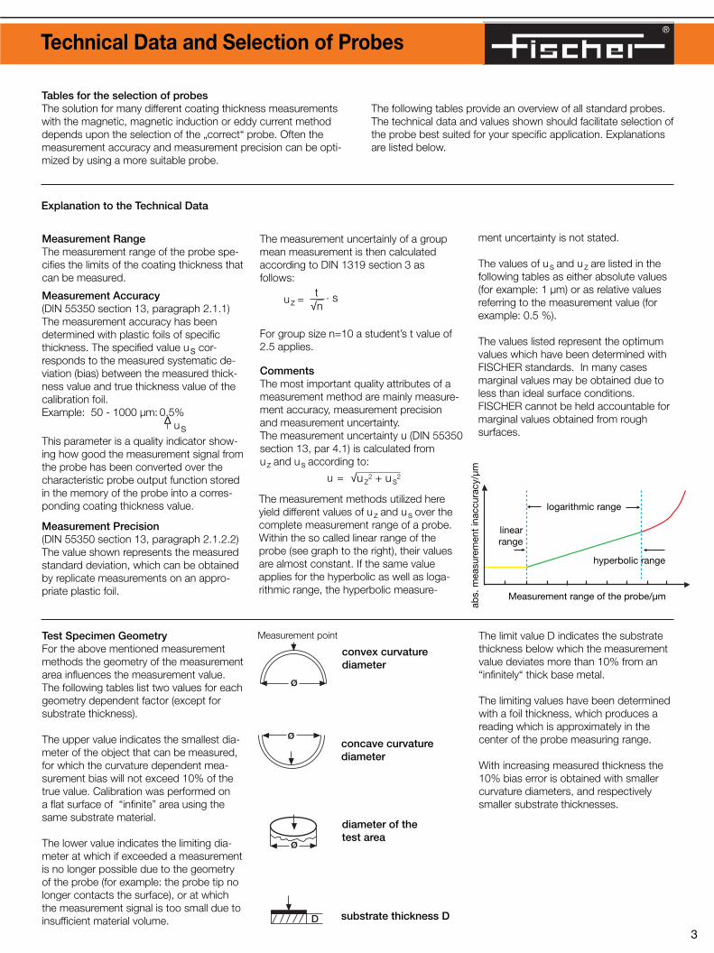
Measurement RangeThe measurement range of the probe spe-cifies the limits of the coating thickness thatcan be measured.
Test Specimen GeometryFor the above mentioned measurementmethods the geometry of the measurementarea influences the measurement value.The following tables list two values for eachgeometry dependent factor (except forsubstrate thickness).
The upper value indicates the smallest dia-meter of the object that can be measured,for which the curvature dependent mea-surement bias will not exceed 10% of thetrue value. Calibration was performed on a flat surface of “infinite” area using thesame substrate material.
The lower value indicates the limiting dia-meter at which if exceeded a measurementis no longer possible due to the geometryof the probe (for example: the probe tip nolonger contacts the surface), or at whichthe measurement signal is too small due toinsufficient material volume.
convex curvaturediameter
concave curvaturediameter
diameter of the test area
substrate thickness D
Measurement point The limit value D indicates the substratethickness below which the measurementvalue deviates more than 10% from an“infinitely“ thick base metal.
The limiting values have been determinedwith a foil thickness, which produces areading which is approximately in thecenter of the probe measuring range.
With increasing measured thickness the10% bias error is obtained with smallercurvature diameters, and respectivelysmaller substrate thicknesses.
CommentsThe most important quality attributes of ameasurement method are mainly measure-ment accuracy, measurement precision and measurement uncertainty.The measurement uncertainty u (DIN 55350section 13, par 4.1) is calculated fromuz and us according to:
u =
The measurement uncertainly of a groupmean measurement is then calculatedaccording to DIN 1319 section 3 asfollows:
uz =
For group size n=10 a student’s t value of2.5 applies.
Measurement Precision(DIN 55350 section 13, paragraph 2.1.2.2)The value shown represents the measuredstandard deviation, which can be obtainedby replicate measurements on an appro-priate plastic foil.
t√n
. s
Explanation to the Technical Data
The characteristic probe output function isstored in the memory chip of the probeconnector and thus the probe contains allinformation required for the measurement.The operator simply recalls the measure-ment application; the system is ready tomeasure immediately. Measurementsperformed at intermittent time intervalstherefore always start with the same refe-rence value.
Tables for the selection of probesThe solution for many different coating thickness measurementswith the magnetic, magnetic induction or eddy current methoddepends upon the selection of the „correct“ probe. Often themeasurement accuracy and measurement precision can be opti-mized by using a more suitable probe.
The following tables provide an overview of all standard probes.The technical data and values shown should facilitate selection ofthe probe best suited for your specific application. Explanationsare listed below.
√uz2 + us
2
ment uncertainty is not stated.
The values of us and uz are listed in thefollowing tables as either absolute values(for example: 1 µm) or as relative valuesreferring to the measurement value (forexample: 0.5 %).
The values listed represent the optimumvalues which have been determined withFISCHER standards. In many casesmarginal values may be obtained due toless than ideal surface conditions.FISCHER cannot be held accountable formarginal values obtained from roughsurfaces.
The measurement methods utilized hereyield different values of uz and us over thecomplete measurement range of a probe.Within the so called linear range of theprobe (see graph to the right), their valuesare almost constant. If the same valueapplies for the hyperbolic as well as loga-rithmic range, the hyperbolic measure-
ø
ø
ø
D
log d normalized probe signal
linearmeasurementrange
logarithmicmeasurementrange
hyper-bolicmeasure-mentrange
linearrange
logarithmic range
Measurement range of the probe/µm
abs.
mea
sure
men
t in
accu
racy
/µm
hyperbolic range
log d(X n1)
0 1 X nX n1
permanent magnet
N
SHall effect sensor
soft iron coreprobe
exciting currentI~
low frequencyalternatingmagnetic field
high frequencyalternatingmagnetic field
measurement signalU = f(d)
measurement signalU = f(d)
non-conductingnon-ferrous substrate}
iron/steel substrate
Nickel thickness Thcoating thickness Th
probe ferrite core
exciting currentI~
non-ferrous substrate
Wirbelströme
coating thickness Th
Memory chip to storeinformation regarding• the probe (measure-,
ment range, model, characteristic number)
• the specimen(geometry, material characteristics �,�)
Probe
Coating
Specimen
®
This technical information material introduces standard mag-netic probes, magnetic induction probes and eddy current
probes to measure coating thickness. The fundamental, phy-sical principles are explained below.
2 3
measurementsignal
U = f(Th)
Measurement Accuracy(DIN 55350 section 13, paragraph 2.1.1)The measurement accuracy has beendetermined with plastic foils of specificthickness. The specified value us cor-responds to the measured systematic de-viation (bias) between the measured thick-ness value and true thickness value of thecalibration foil.Example: 50 - 1000 µm: 0.5%
∆ usThis parameter is a quality indicator show-ing how good the measurement signal fromthe probe has been converted over thecharacteristic probe output function storedin the memory of the probe into a corres-ponding coating thickness value.
Measuring Methods and Processing Measuring Signals Technical Data and Selection of Probes
Magnetic MethodA permanent magnet produces a con-tinuous magnetic field (DIN EN ISO 2178)the strength of which depends upon thethickness of the coating to be measured(Ni/Fe), or the distance between probeand substrate (NF/Fe). The strength of themagnetic field is measured with an appro-priate sensor and the coating thickness iscalculated from this information.
Signal ProcessingThe electrical signal transmitted from theprobe is processed by the measuring in-strument and digitized. The processedsignal is normalized to standardize the pos-sible measuring range and to minimize anydisturbing effects. With type E .... seriessmart probes this signal is then converted
through a characteristic probe outputfunction which is stored in the memory chip of the probe connector, into a mea-surement value indicative of the measuredcoating thickness. With other (older)probes this characteristic function is storedin the measuring system.
Normalization of the probe signal is per-formed as follows:
X n =
The variables are:X o : probe signal from the uncoated sub-
strateX s : probe signal from infinitely thick coa-
ting (saturation thickness)
X : probe signal from the measured coa-ting thickness d.
The normalized signal X n therefore is onlyable to assume values between 0 and 1.
X n is then converted over the characteristicprobe output function into the measuredcoating thickness value d.
X – X oX s – X o
Magnetic Induction MethodThe energizing alternating current pro-duces a low frequency magnetic field (DINEN ISO 2178) the strength of which de-pends upon the distance between theprobe and the substrate. The magnetic fluxdensity is measured by means of a pickupcoil. The induced measurement signal ob-tained is converted into the coating thick-ness value through translation using thecharacteristic probe output function.
Eddy Current MethodThe energizing current produces a highfrequency magnetic field (DIN EN ISO 2360)which induces eddy currents in the sub-strate material (or in the coating material tobe measured with the modified test method).The magnitude of the induced eddy currentsdepends upon the distance (coating thick-ness) between probe and substrate. Themeasurement signal is then evaluated as afunction of the eddy currents produced.
Measurement RangeThe measurement range of the probe spe-cifies the limits of the coating thickness thatcan be measured.
Test Specimen GeometryFor the above mentioned measurementmethods the geometry of the measurementarea influences the measurement value.The following tables list two values for eachgeometry dependent factor (except forsubstrate thickness).
The upper value indicates the smallest dia-meter of the object that can be measured,for which the curvature dependent mea-surement bias will not exceed 10% of thetrue value. Calibration was performed on a flat surface of “infinite” area using thesame substrate material.
The lower value indicates the limiting dia-meter at which if exceeded a measurementis no longer possible due to the geometryof the probe (for example: the probe tip nolonger contacts the surface), or at whichthe measurement signal is too small due toinsufficient material volume.
convex curvaturediameter
concave curvaturediameter
diameter of the test area
substrate thickness D
Measurement point The limit value D indicates the substratethickness below which the measurementvalue deviates more than 10% from an“infinitely“ thick base metal.
The limiting values have been determinedwith a foil thickness, which produces areading which is approximately in thecenter of the probe measuring range.
With increasing measured thickness the10% bias error is obtained with smallercurvature diameters, and respectivelysmaller substrate thicknesses.
CommentsThe most important quality attributes of ameasurement method are mainly measure-ment accuracy, measurement precision and measurement uncertainty.The measurement uncertainty u (DIN 55350section 13, par 4.1) is calculated fromuz and us according to:
u =
The measurement uncertainly of a groupmean measurement is then calculatedaccording to DIN 1319 section 3 asfollows:
uz =
For group size n=10 a student’s t value of2.5 applies.
Measurement Precision(DIN 55350 section 13, paragraph 2.1.2.2)The value shown represents the measuredstandard deviation, which can be obtainedby replicate measurements on an appro-priate plastic foil.
t√n
. s
Explanation to the Technical Data
The characteristic probe output function isstored in the memory chip of the probeconnector and thus the probe contains allinformation required for the measurement.The operator simply recalls the measure-ment application; the system is ready tomeasure immediately. Measurementsperformed at intermittent time intervalstherefore always start with the same refe-rence value.
Tables for the selection of probesThe solution for many different coating thickness measurementswith the magnetic, magnetic induction or eddy current methoddepends upon the selection of the „correct“ probe. Often themeasurement accuracy and measurement precision can be opti-mized by using a more suitable probe.
The following tables provide an overview of all standard probes.The technical data and values shown should facilitate selection ofthe probe best suited for your specific application. Explanationsare listed below.
√uz2 + us
2
ment uncertainty is not stated.
The values of us and uz are listed in thefollowing tables as either absolute values(for example: 1 µm) or as relative valuesreferring to the measurement value (forexample: 0.5 %).
The values listed represent the optimumvalues which have been determined withFISCHER standards. In many casesmarginal values may be obtained due toless than ideal surface conditions.FISCHER cannot be held accountable formarginal values obtained from roughsurfaces.
The measurement methods utilized hereyield different values of uz and us over thecomplete measurement range of a probe.Within the so called linear range of theprobe (see graph to the right), their valuesare almost constant. If the same valueapplies for the hyperbolic as well as loga-rithmic range, the hyperbolic measure-
ø
ø
ø
D
log d normalized probe signal
linearmeasurementrange
logarithmicmeasurementrange
hyper-bolicmeasure-mentrange
linearrange
logarithmic range
Measurement range of the probe/µm
abs.
mea
sure
men
t in
accu
racy
/µm
hyperbolic range
log d(X n1)
0 1 X nX n1
permanent magnet
N
SHall effect sensor
soft iron coreprobe
exciting currentI~
low frequencyalternatingmagnetic field
high frequencyalternatingmagnetic field
measurement signalU = f(d)
measurement signalU = f(d)
non-conductingnon-ferrous substrate}
iron/steel substrate
Nickel thickness Thcoating thickness Th
probe ferrite core
exciting currentI~
non-ferrous substrate
Wirbelströme
coating thickness Th
Memory chip to storeinformation regarding• the probe (measure-,
ment range, model, characteristic number)
• the specimen(geometry, material characteristics �,�)
Probe
Coating
Specimen
®
This technical information material introduces standard mag-netic probes, magnetic induction probes and eddy current
probes to measure coating thickness. The fundamental, phy-sical principles are explained below.
2 3
measurementsignal
U = f(Th)

®
Characteristic values and technical data of probes for the magnetic induction measurement method
Measurementrange
DescriptionOrder Number
Note regarding probe designations:
L: cable length for magnetic induction probes 5 mand for eddy current probes 3 m instead of 1.5 m.
F: Measuring element protected against moist,aggressive media.
T: Intermittent measurements on specimens withtemperatures up to 100 ºC (212 ºF) possible.
* Note: Probe capability (accuracy and precision)tested under controlled conditions.
Ø for 10% error
min. Ø
Ø for 10% error
min. Ø
Ø for 10% error
min. Ø
D for 10% error
0.75 mm (30 mils)
Heat treated steel
yes
---
10 mm (0.4“)
110 mm (4.3“)
ø
ø
ø
D
Type of probeApplication
Probe tip radius
Probe tip material
replaceable probe tip
Height
Diameter/width
Length
(see page 24
0.75 mm (30 mils)
Heat treated steel
yes
23 mm (0.9“)
14 mm (0.6“)
72 mm (2.8“)
0.75 mm (30 mils)
PVD coated
yes
---
10 mm (0.4“)
110 mm (4.3“
0.75 mm (30 mils)
PVD coated
yes
23 mm (0.9“)
14 mm (0.6“)
72 mm (2.8“)
0.75 mm (30 mils)
PVD coated
yes
6.5 mm (0.26“)
5.5 mm (0.22“)
320 mm (12.6“)
0.75 mm (30 mils)
yes
PVD coated
6.5 mm (0.26“)
430 mm (17“)
5.5 mm (0.22“)
flat: ø 8 mm (320 mils)
Polyamide
no
---
100 mm (4“)
18 mm (0.7“)
0.8 mm (32 mils)
Tungsten carbide
no
4.3 mm (0.17“)
4 mm (0.16“)
120 mm (4.7“)
Measurement point
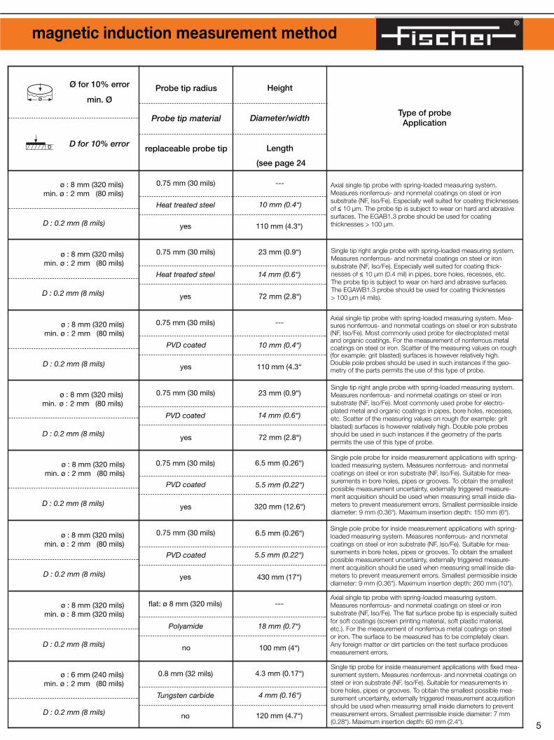
Axial single tip probe with spring-loaded measuring system. Measures nonferrous- and nonmetal coatings on steel or ironsubstrate (NF, Iso/Fe). Especially well suited for coating thicknessesof ≤ 10 µm. The probe tip is subject to wear on hard and abrasivesurfaces. The EGAB1.3 probe should be used for coatingthicknesses > 100 µm.
Single tip right angle probe with spring-loaded measuring system.Measures nonferrous- and nonmetal coatings on steel or ironsubstrate (NF, Iso/Fe). Especially well suited for coating thick-nesses of ≤ 10 µm (0.4 mil) in pipes, bore holes, recesses, etc. The probe tip is subject to wear on hard and abrasive surfaces.The EGAWB1.3 probe should be used for coating thicknesses > 100 µm (4 mils).
Axial single tip probe with spring-loaded measuring system. Mea-sures nonferrous- and nonmetal coatings on steel or iron substrate(NF, Iso/Fe). Most commonly used probe for electroplated metaland organic coatings. For the measurement of nonferrous metalcoatings on steel or iron. Scatter of the measuring values on rough(for example: grit blasted) surfaces is however relatively high.Double pole probes should be used in such instances if the geo-metry of the parts permits the use of this type of probe.
Single tip right angle probe with spring-loaded measuring system.Measures nonferrous- and nonmetal coatings on steel or ironsubstrate (NF, Iso/Fe). Most commonly used probe for electro-plated metal and organic coatings in pipes, bore holes, recesses,etc. Scatter of the measuring values on rough (for example: gritblasted) surfaces is however relatively high. Double pole probesshould be used in such instances if the geometry of the partspermits the use of this type of probe.
Single pole probe for inside measurement applications with spring-loaded measuring system. Measures nonferrous- and nonmetalcoatings on steel or iron substrate (NF, Iso/Fe). Suitable for mea-surements in bore holes, pipes or grooves. To obtain the smallestpossible measurement uncertainty, externally triggered measure-ment acquisition should be used when measuring small inside dia-meters to prevent measurement errors. Smallest permissible insidediameter: 9 mm (0.36“). Maximum insertion depth: 150 mm (6“).
Single pole probe for inside measurement applications with spring-loaded measuring system. Measures nonferrous- and nonmetalcoatings on steel or iron substrate (NF, Iso/Fe). Suitable for mea-surements in bore holes, pipes or grooves. To obtain the smallestpossible measurement uncertainty, externally triggered measure-ment acquisition should be used when measuring small inside dia-meters to prevent measurement errors. Smallest permissible insidediameter: 9 mm (0.36“). Maximum insertion depth: 260 mm (10“).
Axial single tip probe with spring-loaded measuring system.Measures nonferrous- and nonmetal coatings on steel or ironsubstrate (NF, Iso/Fe). The flat surface probe tip is especially suitedfor soft coatings (screen printing material, soft plastic material,etc.). For the measurement of nonferrous metal coatings on steelor iron. The surface to be measured has to be completely clean.Any foreign matter or dirt particles on the test surface producesmeasurement errors.
Single tip probe for inside measurement applications with fixed mea-surement system. Measures nonferrous- and nonmetal coatings onsteel or iron substrate (NF, Iso/Fe). Suitable for measurements inbore holes, pipes or grooves. To obtain the smallest possible mea-surement uncertainty, externally triggered measurement acquisitionshould be used when measuring small inside diameters to preventmeasurement errors. Smallest permissible inside diameter: 7 mm(0.28“). Maximum insertion depth: 60 mm (2.4“).4 5
0-1500 µm0-60 mils
EGA1.3602-118
0-1500 µm0-60 mils
EGAW1.3602-119
EGABW1.3 601-964EGABW1.3.L 602-925
0-1000 µm0-40 mils
0-1000 µm0-40 mils
0-2000 µm0-80 mils
EGAB1.3-SD602-107
V1EGA1HR34 602-109V1EGA1HR34L 602-367
0-1000 µm0-40 mils
EGAB1.3 601-793EGAB1.3.L 602-794EGAB1.3.T 602-359
0-2000 µm0-80 mils
0-2000 µm0-80 mils
EGABI1.3-260601-961
EGABI1.3-150601-932
Measurementaccuracy*
us
Measurementprecision*
s
0-50 µm : 0.25 µm50-1000 µm : 0.5 %
1000-1500 µm : < 2.5 %
0-50 µm : 0.1 µm50-1500 µm : 0.2 %
0-50 µm : 0.25 µm50-1000 µm : 0.5 %
1000-1500 µm : < 2.5 %
0-50 µm : 0.1 µm50-1500 µm : 0.2 %
0-50 µm : 0.5 µm50-1000 µm : 1 %
1000-2000 µm : < 3 %
0-50 µm : 0.5 µm50-1000 µm : 1 %
0-50 µm : 0.15 µm50-1000 µm : 0.3 %
0-50 µm : 0.5 µm50-1000 µm : 1 %
0-50 µm : 0.15 µm50-1000 µm : 0.3 %
0-50 µm : 0.5 µm50-1000 µm : 1 %
0-100 µm : 0.2 µm100-1000 µm : 0.2 %
0-100 µm : 0.5 µm100-1000 µm : 0.5 %
1000-2000 µm : < 3 %
0-50 µm : 0.1 µm50-2000 µm : 0.2 %
0-100 µm : 0.5 µm100-1000 µm : 0.5 %
1000-2000 µm : < 3 %
0-50 µm : 0.1 µm50-2000 µm : 0.2 %
0-100 µm : 0.5 µm100-2000 µm : 0.5 %
ø : 14 mm (550 mils)min. ø : 2 mm (80 mils)
ø : 36 mm (1.4“)min. ø : 10 mm (400 mils)
ø : 14 mm (550 mils)min. ø : 1 mm (40 mils)
ø : 36 mm (1.4“)min. ø : 18 mm (700 mils)
ø : 18 mm (700 mils)min. ø : 2 mm (80 mils)
ø : 35 mm (1.4“)min. ø : 10 mm (400 mils)
ø : 16 mm (640 mils)min. ø : 1 mm (40 mils)
ø : 35 mm (1.4“)min. ø : 18 mm (720 mils)
only for flat specimen
only for flat specimen
ø : 16 mm (630 mils)min. ø : 2 mm (80 mils)
ø : 35 mm (1.4“)min. ø : 9 mm (350 mils)
ø : 16 mm (630 mils)min. ø : 2 mm (80 mils)
ø : 35 mm (1.4“)min. ø : 9 mm (350 mils)
ø : 18 mm (700 mils)min. ø : 2 mm (80 mils)
ø : 35 mm (1.4“)min. ø : 7 mm (280 mils)
ø : 8 mm (320 mils)min. ø : 2 mm (80 mils)
D : 0.2 mm (8 mils)
ø : 8 mm (320 mils)min. ø : 2 mm (80 mils)
D : 0.2 mm (8 mils)
ø : 8 mm (320 mils)min. ø : 2 mm (80 mils)
D : 0.2 mm (8 mils)
ø : 8 mm (320 mils)min. ø : 2 mm (80 mils)
D : 0.2 mm (8 mils)
ø : 8 mm (320 mils)min. ø : 8 mm (320 mils)
D : 0.2 mm (8 mils)
ø : 8 mm (320 mils)min. ø : 2 mm (80 mils)
D : 0.2 mm (8 mils)
ø : 8 mm (320 mils)min. ø : 2 mm (80 mils)
D : 0.2 mm (8 mils)
ø : 6 mm (240 mils)min. ø : 2 mm (80 mils)
D : 0.2 mm (8 mils)
®
Characteristic values and technical data of probes for the magnetic induction measurement method
Measurementrange
DescriptionOrder Number
Note regarding probe designations:
L: cable length for magnetic induction probes 5 mand for eddy current probes 3 m instead of 1.5 m.
F: Measuring element protected against moist,aggressive media.
T: Intermittent measurements on specimens withtemperatures up to 100 ºC (212 ºF) possible.
* Note: Probe capability (accuracy and precision)tested under controlled conditions.
Ø for 10% error
min. Ø
Ø for 10% error
min. Ø
Ø for 10% error
min. Ø
D for 10% error
0.75 mm (30 mils)
Heat treated steel
yes
---
10 mm (0.4“)
110 mm (4.3“)
ø
ø
ø
D
Type of probeApplication
Probe tip radius
Probe tip material
replaceable probe tip
Height
Diameter/width
Length
(see page 24
0.75 mm (30 mils)
Heat treated steel
yes
23 mm (0.9“)
14 mm (0.6“)
72 mm (2.8“)
0.75 mm (30 mils)
PVD coated
yes
---
10 mm (0.4“)
110 mm (4.3“
0.75 mm (30 mils)
PVD coated
yes
23 mm (0.9“)
14 mm (0.6“)
72 mm (2.8“)
0.75 mm (30 mils)
PVD coated
yes
6.5 mm (0.26“)
5.5 mm (0.22“)
320 mm (12.6“)
0.75 mm (30 mils)
yes
PVD coated
6.5 mm (0.26“)
430 mm (17“)
5.5 mm (0.22“)
flat: ø 8 mm (320 mils)
Polyamide
no
---
100 mm (4“)
18 mm (0.7“)
0.8 mm (32 mils)
Tungsten carbide
no
4.3 mm (0.17“)
4 mm (0.16“)
120 mm (4.7“)
Measurement point
Axial single tip probe with spring-loaded measuring system. Measures nonferrous- and nonmetal coatings on steel or ironsubstrate (NF, Iso/Fe). Especially well suited for coating thicknessesof ≤ 10 µm. The probe tip is subject to wear on hard and abrasivesurfaces. The EGAB1.3 probe should be used for coatingthicknesses > 100 µm.
Single tip right angle probe with spring-loaded measuring system.Measures nonferrous- and nonmetal coatings on steel or ironsubstrate (NF, Iso/Fe). Especially well suited for coating thick-nesses of ≤ 10 µm (0.4 mil) in pipes, bore holes, recesses, etc. The probe tip is subject to wear on hard and abrasive surfaces.The EGAWB1.3 probe should be used for coating thicknesses > 100 µm (4 mils).
Axial single tip probe with spring-loaded measuring system. Mea-sures nonferrous- and nonmetal coatings on steel or iron substrate(NF, Iso/Fe). Most commonly used probe for electroplated metaland organic coatings. For the measurement of nonferrous metalcoatings on steel or iron. Scatter of the measuring values on rough(for example: grit blasted) surfaces is however relatively high.Double pole probes should be used in such instances if the geo-metry of the parts permits the use of this type of probe.
Single tip right angle probe with spring-loaded measuring system.Measures nonferrous- and nonmetal coatings on steel or ironsubstrate (NF, Iso/Fe). Most commonly used probe for electro-plated metal and organic coatings in pipes, bore holes, recesses,etc. Scatter of the measuring values on rough (for example: gritblasted) surfaces is however relatively high. Double pole probesshould be used in such instances if the geometry of the partspermits the use of this type of probe.
Single pole probe for inside measurement applications with spring-loaded measuring system. Measures nonferrous- and nonmetalcoatings on steel or iron substrate (NF, Iso/Fe). Suitable for mea-surements in bore holes, pipes or grooves. To obtain the smallestpossible measurement uncertainty, externally triggered measure-ment acquisition should be used when measuring small inside dia-meters to prevent measurement errors. Smallest permissible insidediameter: 9 mm (0.36“). Maximum insertion depth: 150 mm (6“).
Single pole probe for inside measurement applications with spring-loaded measuring system. Measures nonferrous- and nonmetalcoatings on steel or iron substrate (NF, Iso/Fe). Suitable for mea-surements in bore holes, pipes or grooves. To obtain the smallestpossible measurement uncertainty, externally triggered measure-ment acquisition should be used when measuring small inside dia-meters to prevent measurement errors. Smallest permissible insidediameter: 9 mm (0.36“). Maximum insertion depth: 260 mm (10“).
Axial single tip probe with spring-loaded measuring system.Measures nonferrous- and nonmetal coatings on steel or ironsubstrate (NF, Iso/Fe). The flat surface probe tip is especially suitedfor soft coatings (screen printing material, soft plastic material,etc.). For the measurement of nonferrous metal coatings on steelor iron. The surface to be measured has to be completely clean.Any foreign matter or dirt particles on the test surface producesmeasurement errors.
Single tip probe for inside measurement applications with fixed mea-surement system. Measures nonferrous- and nonmetal coatings onsteel or iron substrate (NF, Iso/Fe). Suitable for measurements inbore holes, pipes or grooves. To obtain the smallest possible mea-surement uncertainty, externally triggered measurement acquisitionshould be used when measuring small inside diameters to preventmeasurement errors. Smallest permissible inside diameter: 7 mm(0.28“). Maximum insertion depth: 60 mm (2.4“).4 5
0-1500 µm0-60 mils
EGA1.3602-118
0-1500 µm0-60 mils
EGAW1.3602-119
EGABW1.3 601-964EGABW1.3.L 602-925
0-1000 µm0-40 mils
0-1000 µm0-40 mils
0-2000 µm0-80 mils
EGAB1.3-SD602-107
V1EGA1HR34 602-109V1EGA1HR34L 602-367
0-1000 µm0-40 mils
EGAB1.3 601-793EGAB1.3.L 602-794EGAB1.3.T 602-359
0-2000 µm0-80 mils
0-2000 µm0-80 mils
EGABI1.3-260601-961
EGABI1.3-150601-932
Measurementaccuracy*
us
Measurementprecision*
s
0-50 µm : 0.25 µm50-1000 µm : 0.5 %
1000-1500 µm : < 2.5 %
0-50 µm : 0.1 µm50-1500 µm : 0.2 %
0-50 µm : 0.25 µm50-1000 µm : 0.5 %
1000-1500 µm : < 2.5 %
0-50 µm : 0.1 µm50-1500 µm : 0.2 %
0-50 µm : 0.5 µm50-1000 µm : 1 %
1000-2000 µm : < 3 %
0-50 µm : 0.5 µm50-1000 µm : 1 %
0-50 µm : 0.15 µm50-1000 µm : 0.3 %
0-50 µm : 0.5 µm50-1000 µm : 1 %
0-50 µm : 0.15 µm50-1000 µm : 0.3 %
0-50 µm : 0.5 µm50-1000 µm : 1 %
0-100 µm : 0.2 µm100-1000 µm : 0.2 %
0-100 µm : 0.5 µm100-1000 µm : 0.5 %
1000-2000 µm : < 3 %
0-50 µm : 0.1 µm50-2000 µm : 0.2 %
0-100 µm : 0.5 µm100-1000 µm : 0.5 %
1000-2000 µm : < 3 %
0-50 µm : 0.1 µm50-2000 µm : 0.2 %
0-100 µm : 0.5 µm100-2000 µm : 0.5 %
ø : 14 mm (550 mils)min. ø : 2 mm (80 mils)
ø : 36 mm (1.4“)min. ø : 10 mm (400 mils)
ø : 14 mm (550 mils)min. ø : 1 mm (40 mils)
ø : 36 mm (1.4“)min. ø : 18 mm (700 mils)
ø : 18 mm (700 mils)min. ø : 2 mm (80 mils)
ø : 35 mm (1.4“)min. ø : 10 mm (400 mils)
ø : 16 mm (640 mils)min. ø : 1 mm (40 mils)
ø : 35 mm (1.4“)min. ø : 18 mm (720 mils)
only for flat specimen
only for flat specimen
ø : 16 mm (630 mils)min. ø : 2 mm (80 mils)
ø : 35 mm (1.4“)min. ø : 9 mm (350 mils)
ø : 16 mm (630 mils)min. ø : 2 mm (80 mils)
ø : 35 mm (1.4“)min. ø : 9 mm (350 mils)
ø : 18 mm (700 mils)min. ø : 2 mm (80 mils)
ø : 35 mm (1.4“)min. ø : 7 mm (280 mils)
ø : 8 mm (320 mils)min. ø : 2 mm (80 mils)
D : 0.2 mm (8 mils)
ø : 8 mm (320 mils)min. ø : 2 mm (80 mils)
D : 0.2 mm (8 mils)
ø : 8 mm (320 mils)min. ø : 2 mm (80 mils)
D : 0.2 mm (8 mils)
ø : 8 mm (320 mils)min. ø : 2 mm (80 mils)
D : 0.2 mm (8 mils)
ø : 8 mm (320 mils)min. ø : 8 mm (320 mils)
D : 0.2 mm (8 mils)
ø : 8 mm (320 mils)min. ø : 2 mm (80 mils)
D : 0.2 mm (8 mils)
ø : 8 mm (320 mils)min. ø : 2 mm (80 mils)
D : 0.2 mm (8 mils)
ø : 6 mm (240 mils)min. ø : 2 mm (80 mils)
D : 0.2 mm (8 mils)

®
Characteristic values and technical data of probes for the magnetic induction measurement method
Type of probeApplication
Ø for 10% error
min. Ø
D for 10% error
ø
D
Axial single tip probe with spring-loaded measuring system.Measures nonferrous- and nonmetal coatings on steel or ironsubstrate (NF, Iso/Fe). Due to the larger probe tip diameter bettersuited for rough surfaces than the EGAB1.3 probe.
Axial single tip probe with spring-loaded measuring system.Measures nonferrous- and nonmetal coatings on steel or ironsubstrate (NF, Iso/Fe). Due to the larger probe tip diameter bettersuited for rough surfaces than the EGABW1.3 probe.
Axial single tip probe with spring-loaded measuring system.Measures nonferrous- and nonmetal coatings on steel or ironsubstrate (NF, Iso/Fe). Has the largest measurement range of all single tip probes. Due to unshielded magnetic field largergeometric influence, however smaller tilting effect.
Single tip angle probe with spring-loaded measuring system.Measures nonferrous- and nonmetal coatings on steel or ironsubstrate (NF, Iso/Fe). Same as EGB2 probe, however preferablyused for measurements in pipes, bore holes or recesses.
Double pole probe for angular measurements with fixed measure-ment system. Measures nonferrous- and nonmetal coatings onsteel or iron substrate (NF, Iso/Fe). Double pole probe producingthe lowest possible measurement uncertainty. The uncoatedprobe tips make this probe especially suited for thin coatings (forexample: lubricant and phosphate coatings). Greater measuringprecision on rough surfaces than single tip probes, however fasterprobe tip wear than with EKB4 probe.
Double pole probe for angular measurements with fixed mea-surement system. Measures nonferrous- and nonmetal coatingson steel or iron substrate (NF, Iso/Fe). Well suited for thin coatings.Higher measurement precision on rough surfaces than single pole probes.
Double pole probe for inside measurements with spring-loadedmeasuring system. Measures nonferrous- and nonmetal coatingson steel or iron substrate (NF, Iso/Fe). Suitable for measurement inbore holes, pipes or grooves. Greater measuring precision onrough surfaces than with EGABI1.3 -150 (260) probe.Smallest permissible inside diameter: 8.5 mm (0.34“)Maximum insertion depth: 185 mm (7.4“)
Axial double-tip measurement probe with spring-loaded measuringelement. Measures nonferrous and nonmetal coatings on steel oriron (NE, Iso/Fe). Especially well suited for thin layers (phosphorouscoatings) because of uncoated probe tips. Higher repeatabilitythan single tip probes when measuring rough surfaces. Springloaded measuring system allows exact positioning and constantpressure force, which is advantageous for measuring weakcoatings.
Measurement range
DescriptionOrder Number
Measurementaccuracy*
us
Measurementprecision*
s
Ø for 10% error
min. Øø
Measurement point
Ø for 10% error
min. Ø
ø
Note regarding probe designations:
L: cable length for magnetic induction probes 5 mand for eddy current probes 3 m instead of 1.5 m.
F: Measuring element protected against moist,aggressive media.
T: Intermittent measurements on specimens withtemperatures up to 100 ºC (212 ºF) possible.
* Note: Probe capability (accuracy and precision)tested under controlled conditions.
6 7
0-50 µm : 0.25 µm50-500 µm : 0.5 %
500-1500 µm : < 1 %
0-50 µm : 0.15 µm50-1500 µm : 0.3 %
EGAW2H602-122
0-50 µm : 0.25 µm50-500 µm : 0.5 %
500-1500 µm : < 1 %
0-50 µm : 0.15 µm50-1500 µm : 0.3 %
EGB2602-023
0-0,2 mm : 0.002 mm0,2-3 mm : 1 %
3-5 mm : < 5 %
0-0,2 mm : 0.0005 mm0,2-5 mm : 0.3 %
EGBW2602-024
0-0,2 mm : 0.002 mm0,2-3 mm : 1 %
3-5 mm : < 5 %
0-0,2 mm : 0.0005 mm0,2-5 mm : 0.3 %
EK4602-123
0-100 µm : 1 µm100-2000 µm : 1 %
0-25 µm : 0.1 µm25-2000 µm : 0.4 %
0-100 µm : 1.5 µm100-2000 µm : 1.5 %
0-25 µm : 0.1 µm25-2000 µm : 0.4 %
EKB4602-108
0-100 µm : 0.5 µm100-2000 µm : 0.5 %
0-50 µm : 0.15 µm50-2000 µm : 0.3 %
V1EKB4602-126
0-100 µm : 0.5 µm100-2000 µm : 0.5 %
0-50 µm : 0.15 µm50-2000 µm : 0.3 %
0-1500 µm0-60 mils
EGA2H 602-121EGA2HF 602-754
0-1500 µm0-60 mils
0-5 mm0-200 mils
0-5 mm0-200 mils
0-2000 µm0-80 mils
0-2000 µm0-80 mils
0-2000 µm0-80 mils
V7EK4 602-582V7EK4L 602-605
0-2000 µm0-80 mils
ø : 22 mm (870 mils)min. ø : 2 mm (80 mils)
ø : 38 mm (1.5“)min. ø : 20 mm (800 mils)
ø : 20 mm (800 mils)min. ø : 2 mm (80 mils)
ø : 38 mm (1.5“)min. ø : 20 mm (800 mils)
ø : 20 mm (800 mils)min. ø : 2 mm (80 mils)
ø : 38 mm (1.5“)min. ø : 13 mm (510 mils)
ø : 22 mm (870 mils)min. ø : 2 mm (80 mils)
ø : 38 mm (1.5“)min. ø : 13 mm (510 mils)
ø : 30 mm (1.2“)min. ø : 2 mm (80 mils)
ø : 40 mm (1.6“)min. ø : 18 mm (700 mils)
ø : 30 mm (1.2“)min. ø : 2 mm (80 mils)
ø : 40 mm (1.6“)min. ø : 9 mm (350 mils)
ø : 25 mm (990 mils)min. ø : 2 mm (80 mils)
ø : 34 mm (1.3“)min. ø : 18 mm (700 mils)
ø : 25 mm (990 mils)min. ø : 2 mm (80 mils)
ø : 34 mm (1.3“)min. ø : 22 mm (870 mils)
ø : 30 mm (1.2“)min. ø : 15 mm (590 mils)
D : 0.4 mm (16 mils)
ø : 30 mm (1.2“)min. ø : 15 mm (590 mils)
D : 0.4 mm (16 mils)
ø : 30 mm (1.2“)min. ø : 15 mm (590 mils)
D : 0.4 mm (16 mils)
ø : 30 mm (1.2“)min. ø : 15 mm (590 mils)
D : 0.4 mm (16 mils)
ø : 12 mm (470 mils)min. ø : 2 mm (80 mils)
D : 0.25 mm (10 mils)
ø : 12 mm (470 mils)min. ø : 2 mm (80 mils)
D : 0.25 mm (10 mils)
Probe tip radius
Probe tip material
replaceable probe tip
ø : 15 mm (590 mils)min. ø : 2 mm (80 mils)
ø : 15 mm (590 mils)min. ø : 2 mm (80 mils)
D : 0.4 mm (16 mils)
2.25 mm (88 mils)
Tungsten carbide
yes
---
13 mm (0.5“)
80 mm (3.2“)
2.25 mm (88 mils)
Tungsten carbide
yes
23 mm (0.9“)
14 mm (0.6“)
72 mm (2.8“)
1.0 mm (40 mils)
PVD coated
yes
---
10 mm (0.4“)
110 mm (4.3“)
1.0 mm (40 mils)
PVD coated
yes
23 mm (0.9“)
14 mm (0.6“)
72 mm (2.8“)
1.25 mm (49 mils)
Heat treated steel
yes
21 mm (0.8“)
12 mm (0.5“)
18 mm (0.7“)
1.25 mm (49 mils)
PVD coated
yes
21 mm (0.8“)
12 mm (0.5“)
18 mm (0.7“)
1.25 mm (49 mils)
PVD coated
yes
---
8.5 mm (0.3“)
300 mm (11.8“)
1.25 mm (49 mils)
Heat treated steel
yes
---
20 mm (0.8“)
70 mm (2.8“)
ø : 15 mm (590 mils)min. ø : 2 mm (80 mils)
Height
Diameter/width
Length
(see page 24)

®
Characteristic values and technical data of probes for the magnetic induction measurement method
Ø for 10% error
min. Øø
Ø for 10% error
min. Ø
Ø for 10% error
min. Ø
D for 10% error
ø
ø
D
8 9
Measurement point
ø : 50 mm (2“)min. ø : 2 mm (80 mils)
ø : 75 mm (3“)min. ø : 24 mm (950 mils)
ø : 50 mm (2“)min. ø : 2 mm (80 mils)
∞∞
ø : 50 mm (2“)min. ø : 2 mm (80 mils)
ø : 75 mm (3“)min. ø : 24 mm (950 mils)
0-0.5 mm : 0.005 mm0.5-8 mm : 1 %
0-0.5 mm : 0.0025 mm0.5-8 mm : 0.5 %
0-8 mm0-320 mils
0-0.5 mm : 0.005 mm0.5-8 mm : 1 %
0-0.5 mm : 0.0015 mm0.5-8 mm : 0.3 %
V1EKB10602-676
0-8 mm0-320 mils
0-0.5 mm : 0.01 mm0.5-8 mm : 2 %
0-0.5 mm : 0.0025 mm0.5-8 mm : 0.5 %
EKB10602-225
0-8 mm0-320 mils
EKB10-OD EKB10L-OD
Measurementrange
DescriptionOrder Number
Measurementaccuracy*
us
Measurementprecision*
s
0-100 µm : 1 µm100-2000 µm : 1 %
0-50 µm : 0.15 µm50-2000 µm : 0.3 %
ø : 20 mm (800 mils)min. ø : 2 mm ( 80 mils)
ø : 38 mm (1.5“)min. ø : 20 mm ( 800 mils)
0-2000 µm0-80 mils
V7EKB4 V7EKB4L
602-583602-606
602-165602-760
ø : 60 mm (2.4“)min. ø : 10 mm (400 mils)
ø : 85 mm (3.3“)min. ø : 20 mm (800 mils)
0-15 mm0-590 mils
0-1 mm : 0.02 mm1-7 mm : 2 %
7-15 mm : < 5 %
0-0.5 mm : 0.01 mm0.5-15 mm : 2 %
EKB25 EKB25L
601-952602-913
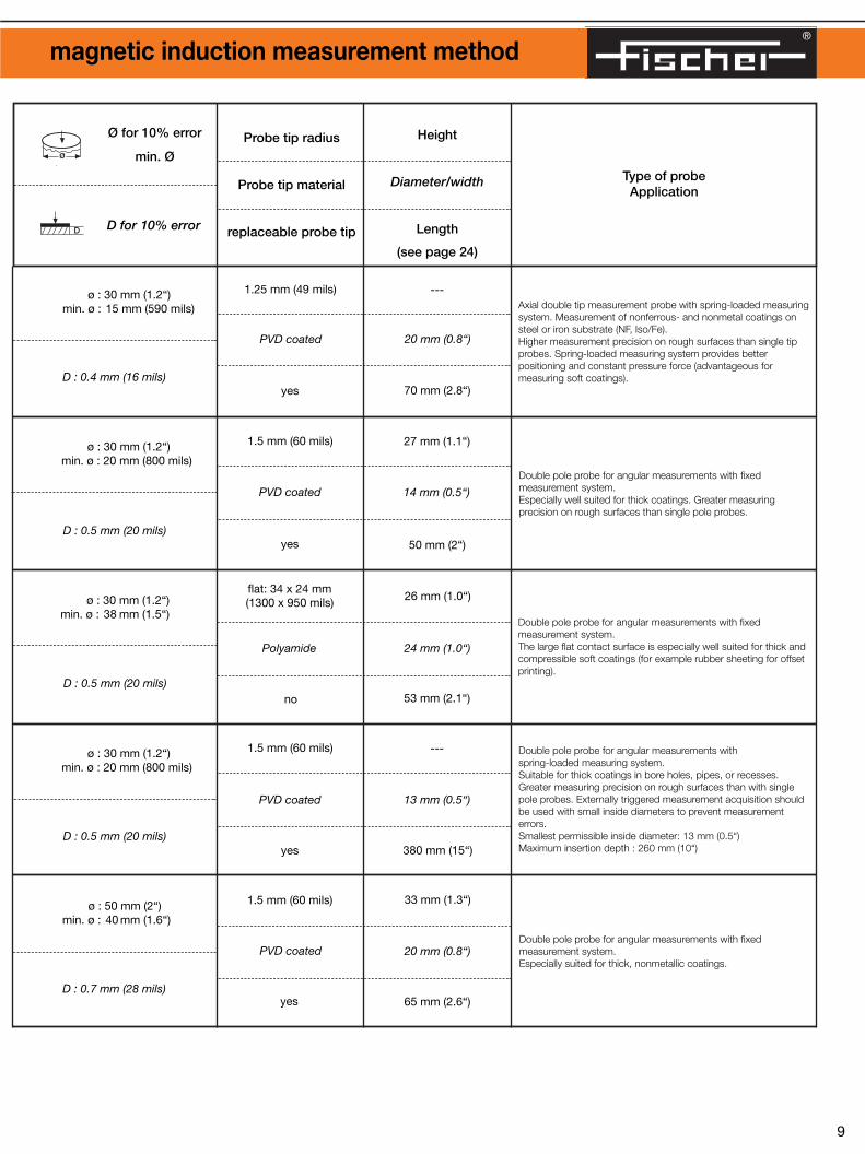
Note concerning the application of probes using the magnetic induction measurement method:Please consult with the manufacturer before measuring electrically conducting coatings with thicknesses > 500 µm (20 mils).
Note regarding probe designations:
L: cable length for magnetic induction probes 5 mand for eddy current probes 3 m instead of 1.5 m.
F: Measuring element protected against moist,aggressive media.
T: Intermittent measurements on specimens withtemperatures up to 100 ºC (212 ºF) possible.
* Note: Probe capability (accuracy and precision)tested under controlled conditions.
ø : 30 mm (1.2“)min. ø : 20 mm (800 mils)
D : 0.5 mm (20 mils)
ø : 30 mm (1.2“)min. ø : 38 mm (1.5“)
D : 0.5 mm (20 mils)
ø : 30 mm (1.2“)min. ø : 20 mm (800 mils)
D : 0.5 mm (20 mils)
1.25 mm (49 mils)
PVD coated
yes
---
20 mm (0.8“)
70 mm (2.8“)
1.5 mm (60 mils)
PVD coated
yes
27 mm (1.1“)
14 mm (0.5“)
50 mm (2“)
flat: 34 x 24 mm(1300 x 950 mils)
Polyamide
no
26 mm (1.0“)
24 mm (1.0“)
53 mm (2.1“)
1.5 mm (60 mils)
PVD coated
yes
---
13 mm (0.5“)
380 mm (15“)
D : 0.4 mm (16 mils)
ø : 30 mm (1.2“)min. ø : 15 mm (590 mils)
Type of probeApplication
Probe tip radius
Probe tip material
replaceable probe tip
Height
Diameter/width
Length
(see page 24)
Axial double tip measurement probe with spring-loaded measuringsystem. Measurement of nonferrous- and nonmetal coatings onsteel or iron substrate (NF, Iso/Fe).Higher measurement precision on rough surfaces than single tipprobes. Spring-loaded measuring system provides betterpositioning and constant pressure force (advantageous formeasuring soft coatings).
Double pole probe for angular measurements with fixedmeasurement system.Especially well suited for thick coatings. Greater measuringprecision on rough surfaces than single pole probes.
Double pole probe for angular measurements with fixedmeasurement system.The large flat contact surface is especially well suited for thick andcompressible soft coatings (for example rubber sheeting for offsetprinting).
Double pole probe for angular measurements with spring-loaded measuring system.Suitable for thick coatings in bore holes, pipes, or recesses.Greater measuring precision on rough surfaces than with singlepole probes. Externally triggered measurement acquisition shouldbe used with small inside diameters to prevent measurementerrors.Smallest permissible inside diameter: 13 mm (0.5“)Maximum insertion depth : 260 mm (10“)
ø : 50 mm (2“)min. ø : 40 mm (1.6“)
D : 0.7 mm (28 mils)
1.5 mm (60 mils)
PVD coated
yes
33 mm (1.3“)
20 mm (0.8“)
65 mm (2.6“)
Double pole probe for angular measurements with fixedmeasurement system.Especially suited for thick, nonmetallic coatings.
®
Characteristic values and technical data of probes for the magnetic induction measurement method
Ø for 10% error
min. Øø
Ø for 10% error
min. Ø
Ø for 10% error
min. Ø
D for 10% error
ø
ø
D
8 9
Measurement point
ø : 50 mm (2“)min. ø : 2 mm (80 mils)
ø : 75 mm (3“)min. ø : 24 mm (950 mils)
ø : 50 mm (2“)min. ø : 2 mm (80 mils)
∞∞
ø : 50 mm (2“)min. ø : 2 mm (80 mils)
ø : 75 mm (3“)min. ø : 24 mm (950 mils)
0-0.5 mm : 0.005 mm0.5-8 mm : 1 %
0-0.5 mm : 0.0025 mm0.5-8 mm : 0.5 %
0-8 mm0-320 mils
0-0.5 mm : 0.005 mm0.5-8 mm : 1 %
0-0.5 mm : 0.0015 mm0.5-8 mm : 0.3 %
V1EKB10602-676
0-8 mm0-320 mils
0-0.5 mm : 0.01 mm0.5-8 mm : 2 %
0-0.5 mm : 0.0025 mm0.5-8 mm : 0.5 %
EKB10602-225
0-8 mm0-320 mils
EKB10-OD EKB10L-OD
Measurementrange
DescriptionOrder Number
Measurementaccuracy*
us
Measurementprecision*
s
0-100 µm : 1 µm100-2000 µm : 1 %
0-50 µm : 0.15 µm50-2000 µm : 0.3 %
ø : 20 mm (800 mils)min. ø : 2 mm ( 80 mils)
ø : 38 mm (1.5“)min. ø : 20 mm ( 800 mils)
0-2000 µm0-80 mils
V7EKB4 V7EKB4L
602-583602-606
602-165602-760
ø : 60 mm (2.4“)min. ø : 10 mm (400 mils)
ø : 85 mm (3.3“)min. ø : 20 mm (800 mils)
0-15 mm0-590 mils
0-1 mm : 0.02 mm1-7 mm : 2 %
7-15 mm : < 5 %
0-0.5 mm : 0.01 mm0.5-15 mm : 2 %
EKB25 EKB25L
601-952602-913
Note concerning the application of probes using the magnetic induction measurement method:Please consult with the manufacturer before measuring electrically conducting coatings with thicknesses > 500 µm (20 mils).
Note regarding probe designations:
L: cable length for magnetic induction probes 5 mand for eddy current probes 3 m instead of 1.5 m.
F: Measuring element protected against moist,aggressive media.
T: Intermittent measurements on specimens withtemperatures up to 100 ºC (212 ºF) possible.
* Note: Probe capability (accuracy and precision)tested under controlled conditions.
ø : 30 mm (1.2“)min. ø : 20 mm (800 mils)
D : 0.5 mm (20 mils)
ø : 30 mm (1.2“)min. ø : 38 mm (1.5“)
D : 0.5 mm (20 mils)
ø : 30 mm (1.2“)min. ø : 20 mm (800 mils)
D : 0.5 mm (20 mils)
1.25 mm (49 mils)
PVD coated
yes
---
20 mm (0.8“)
70 mm (2.8“)
1.5 mm (60 mils)
PVD coated
yes
27 mm (1.1“)
14 mm (0.5“)
50 mm (2“)
flat: 34 x 24 mm(1300 x 950 mils)
Polyamide
no
26 mm (1.0“)
24 mm (1.0“)
53 mm (2.1“)
1.5 mm (60 mils)
PVD coated
yes
---
13 mm (0.5“)
380 mm (15“)
D : 0.4 mm (16 mils)
ø : 30 mm (1.2“)min. ø : 15 mm (590 mils)
Type of probeApplication
Probe tip radius
Probe tip material
replaceable probe tip
Height
Diameter/width
Length
(see page 24)
Axial double tip measurement probe with spring-loaded measuringsystem. Measurement of nonferrous- and nonmetal coatings onsteel or iron substrate (NF, Iso/Fe).Higher measurement precision on rough surfaces than single tipprobes. Spring-loaded measuring system provides betterpositioning and constant pressure force (advantageous formeasuring soft coatings).
Double pole probe for angular measurements with fixedmeasurement system.Especially well suited for thick coatings. Greater measuringprecision on rough surfaces than single pole probes.
Double pole probe for angular measurements with fixedmeasurement system.The large flat contact surface is especially well suited for thick andcompressible soft coatings (for example rubber sheeting for offsetprinting).
Double pole probe for angular measurements with spring-loaded measuring system.Suitable for thick coatings in bore holes, pipes, or recesses.Greater measuring precision on rough surfaces than with singlepole probes. Externally triggered measurement acquisition shouldbe used with small inside diameters to prevent measurementerrors.Smallest permissible inside diameter: 13 mm (0.5“)Maximum insertion depth : 260 mm (10“)
ø : 50 mm (2“)min. ø : 40 mm (1.6“)
D : 0.7 mm (28 mils)
1.5 mm (60 mils)
PVD coated
yes
33 mm (1.3“)
20 mm (0.8“)
65 mm (2.6“)
Double pole probe for angular measurements with fixedmeasurement system.Especially suited for thick, nonmetallic coatings.

®
Characteristic values and technical data of probes for the eddy current measuring method
Ø for 10% error
min. Øø
Ø for 10% error
min. Ø
Ø for 10% error
min. Ø
D for 10% error
ø
ø
D
10 11
Measurement point
ø : 18 mm (720 mils)min. ø : 1 mm ( 40 mils)
ø : 30 mm (1.2“)min. ø : 20 mm (800 mils)
ø : 100 mm (4“)min. ø : 10 mm (400 mils)
ø : 140 mm (5.5“)min. ø : 14 mm (550 mils)
0-30 mm0-1200 mils
0-1 mm : 0.05 mm1-10 mm : 5 %
10-30 mm : < 7 %
0-50 µm : 0.3 µm50-700 µm : < 2 %
0-50 µm : 0.1 µm50-700 µm : < 0.3 %
0-1 mm : 0.02 mm1-30 mm : 2%
EGA06H 602-936EGA06H-L 602-626
EGA06H-MC603-092
V2EGA06H603-112
0-700 µm0-28 mils
ø : 18 mm (720 mils)min. ø : 1 mm ( 40 mils)
ø : 18 mm (720 mils)min. ø : 1 mm ( 40 mils)
ø : 30 mm (1.2“)min. ø : 20 mm (800 mils)
---
0-70 µm : 0.3 µm70-700 µm : < 2 %
0-70 µm : 0.08 µm70-700 µm : < 0.08 %
0-50 µm : 0.3 µm50-700 µm : < 2 %
0-50 µm : 0.1 µm50-700 µm : < 0.3 %
0-700 µm0-28 mils
0-700 µm0-28 mils
EK50 602-127EK50L 602-923
Measurementrange
DescriptionOrder Number
Measurementaccuracy*
us
Measurementprecision*
s
Note regarding probe designations:
L: cable length for magnetic induction probes 5 mand for eddy current probes 3 m instead of 1.5 m.
F: Measuring element protected against moist,aggressive media.
T: Intermittent measurements on specimens withtemperatures up to 100 ºC (212 ºF) possible.
* Note: Probe capability (accuracy and precision)tested under controlled conditions.
ø : 5 mm (200 mils)min. ø : 2 mm (80 mils)
D : 0.25 mm (10 mils)
ø : 84 mm (3.3“)min. ø : 70 mm (2.8“)
D : 1.2 mm (47 mils)
2.5 mm (98 mils)
Heat treated steel
yes
33 mm (1.3“)
20 mm (0.8“)
95 mm (3.7“)
0.3 mm (12 mils)
Tungsten carbide
no
110 mm (4.4“)
13 mm (0.52“)
---
ø : 5 mm (200 mils)min. ø : 2 mm (80 mils)
D : 0.25 mm (10 mils)
ø : 5 mm (200 mils)min. ø : 2 mm (80 mils)
D : 0.25 mm (10 mils)
0.3 mm (12 mils)
Tungsten carbide
no
0.3 mm (12 mils)
Tungsten carbide
no
110 mm (4.4“)
13 mm (0.52“)
---
---
10 mm (0.4“)
110 mm (4.4“)
Double pole probe for angular measurements with fixedmeasurement system.Especially suited for very thick, nonmetallic coatings. For austenitic stainless steel coatings smaller measurement errorsdue to ferromagnetic delta ferrite content than with all other typesof probes.
Axial single tip measurement probe with spring-loaded measuringsystem. Measures electrically nonconducting or nonferrouscoatings on steel or iron (NF/Fe).Mechanical design especially suited for installation in customer-specific probe fixtures or guide devices for precise probepositioning.
Axial single tip measurement probe with spring-loaded measuringtsystem. Measures electrically nonconducting or nonferrouscoatings on steel or iron (NF/Fe).Mechanical design especially suited for installation in customer-specific probe fixtures or guide devices for precise probepositioning.
Measures electrically nonconducting or nonferrous metal coatings on steel or iron (NF/Fe). Measuring element same as with EGA06H probe. Especially well suited for the integration in automatedmeasurement systems. No measurement tip wear even afterseveral million measurement cycles when used properly. Suited for cylindrical specimen with diameter range 8 to 25 mm.(0.32“ to 1“). Other diameters on request.
Type of probeApplication
Probe tip radius
Probe tip material
replaceable probe tip
Height
Diameter/width
Length
(see page 24)
®
Characteristic values and technical data of probes for the eddy current measuring method
Ø for 10% error
min. Øø
Measurement point
Ø for 10% error
min. Ø
Ø for 10% error
min. Ø
D for 10% error
ø
ø
D
12 13
ø : 1200 mm (47“)min. ø : 200 mm (7.9“)
∞∞
ø : 160 mm (6.3“)min. ø : 2 mm (80 mils)
ø : 160 mm (6.3“)min. ø : 40 mm (1.6“)
ø : 60 mm (2.4“)min. ø : 2 mm (80 mils)
ø : 55 mm (2.2“)min. ø : 9 mm (350 mils)
ø : 50 mm (2“)min. ø : 2 mm (80 mils)
ø : 50 mm (2“)min. ø : 34 mm (1.6“)
ø : 50 mm (2“)min. ø : 2 mm (80 mils)
ø : 50 mm (2“)min. ø : 30 mm (1.2“)
ø : 50 mm (2“)min. ø : 2 mm (80 mils)
∞∞
ø : 50 mm (2“)min. ø : 2 mm (80 mils)
ø : 55 mm (2.2“)min. ø : 30 mm (1.2“)
ø : 50 mm (2“)min. ø : 2 mm (80 mils)
ø : 50 mm (2“)min. ø : 30 mm (1.2“)
Measurementrange
DescriptionOrder Number
Measurementaccuracy*
us
Measurementprecision*
s
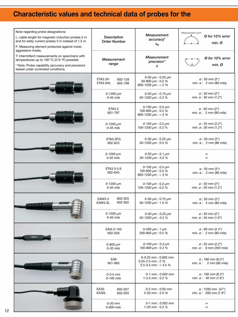
0-1200 µm0-45 mils
0-50 µm : 0.25 µm50-800 µm : 0.5 %
800-1200 µm : < 2 %
0-50 µm : 0.15 µm50-1200 µm : 0.3 %
ETA3.3FG602-623
0-50 µm : 0.25 µm50-1200 µm : 0.5 %
0-50 µm : 0.1 µm50-1200 µm : 0.2 %
ETA3.3601-797
0-100 µm : 0.5 µm100-800 µm : 0.5 %
800-1200 µm : < 3 %
0-100 µm : 0.2 µm100-1200 µm : 0.2 %
ETA3.3-5.6602-645
0-100 µm : 0.5 µm100-800 µm : 0.5 %
800-1200 µm : < 3 %
0-100 µm : 0.2 µm100-1200 µm : 0.2 %
0-1200 µm0-45 mils
0-50 µm : 0.75 µm50-1200 µm : 1.5 %
0-50 µm : 0.25 µm50-1200 µm : 0.5 %
EAI3.3-150602-026
0-200 µm : 1 µm200-800 µm : 0.5 %
0-100 µm : 0.3 µm100-800 µm : 0.3 %
EA9601-965
0-0.25 mm : 0.005 mm0.25-2.5 mm : 2 %2.5-3.5 mm : < 3.5 %
0-1 mm : 0.002 mm1-3.5 mm : 0.2 %
0-20 mm0-800 mils
0-2 mm : 0.05 mm2-20 mm : 2.5 %
0-1 mm : 0.002 mm1-20 mm : 0.2 %
ETA3.3H ETA3.3HL
602-128602-799
EAW3.3EAW3.3L
602-025602-922
EA30EA30L
602-027602-633
0-1200 µm0-45 mils
0-1200 µm0-45 mils
0-1200 µm0-45 mils
0-800 µm0-32 mils
0-3.5 mm0-140 mils
Note regarding probe designations:
L: cable length for magnetic induction probes 5 mand for eddy current probes 3 m instead of 1.5 m.
F: Measuring element protected against moist,aggressive media.
T: Intermittent measurements on specimens withtemperatures up to 100 ºC (212 ºF) possible.
* Note: Probe capability (accuracy and precision)tested under controlled conditions.
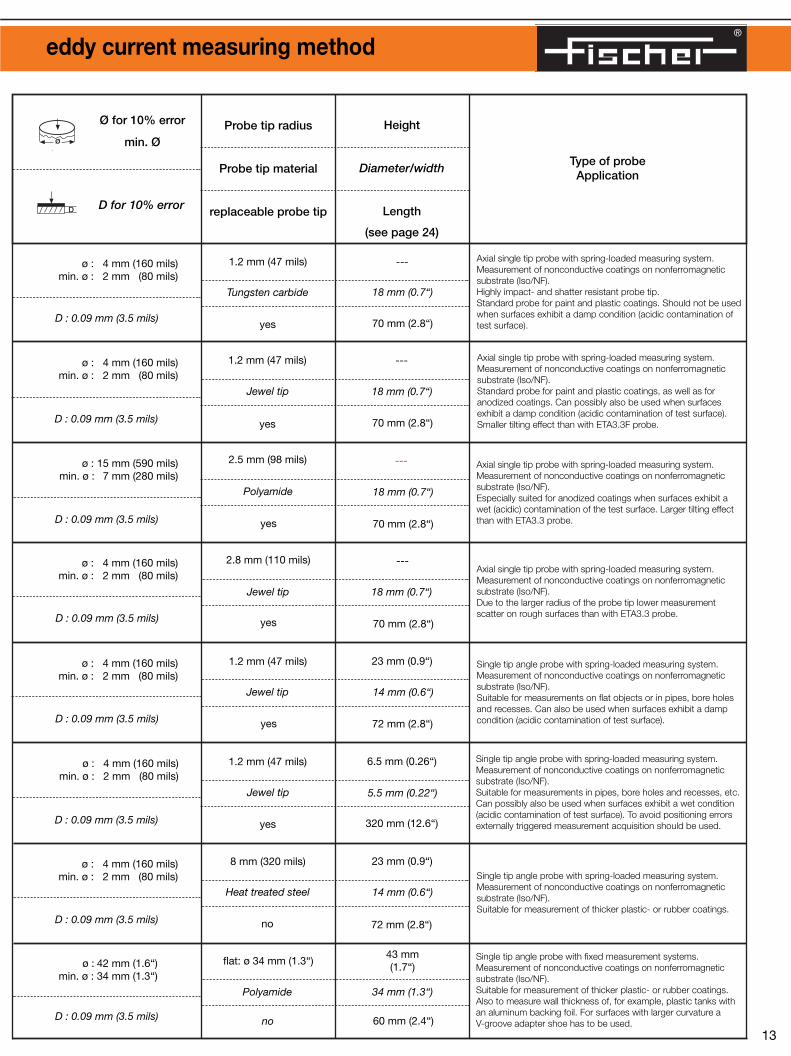
ø : 42 mm (1.6“)min. ø : 34 mm (1.3“)
D : 0.09 mm (3.5 mils)
ø : 4 mm (160 mils)min. ø : 2 mm (80 mils)
D : 0.09 mm (3.5 mils)
ø : 4 mm (160 mils)min. ø : 2 mm (80 mils)
D : 0.09 mm (3.5 mils)
ø : 4 mm (160 mils)min. ø : 2 mm (80 mils)
D : 0.09 mm (3.5 mils)
ø : 4 mm (160 mils)min. ø : 2 mm (80 mils)
D : 0.09 mm (3.5 mils)
ø : 15 mm (590 mils)min. ø : 7 mm (280 mils)
D : 0.09 mm (3.5 mils)
ø : 4 mm (160 mils)min. ø : 2 mm (80 mils)
D : 0.09 mm (3.5 mils)
ø : 4 mm (160 mils)min. ø : 2 mm (80 mils)
D : 0.09 mm (3.5 mils)
Type of probeApplication
Probe tip radius
Probe tip material
replaceable probe tip
1.2 mm (47 mils)
Tungsten carbide
yes
---
18 mm (0.7“)
70 mm (2.8“)
1.2 mm (47 mils)
Jewel tip
yes
---
18 mm (0.7“)
70 mm (2.8“)
2.5 mm (98 mils)
Polyamide
yes
---
18 mm (0.7“)
70 mm (2.8“)
2.8 mm (110 mils)
Jewel tip
yes
---
18 mm (0.7“)
70 mm (2.8“)
1.2 mm (47 mils)
Jewel tip
yes
23 mm (0.9“)
14 mm (0.6“)
72 mm (2.8“)
1.2 mm (47 mils)
Jewel tip
yes
6.5 mm (0.26“)
5.5 mm (0.22“)
320 mm (12.6“)
8 mm (320 mils)
Heat treated steel
no
23 mm (0.9“)
14 mm (0.6“)
72 mm (2.8“)
flat: ø 34 mm (1.3“)
Polyamide
no
43 mm(1.7“)
34 mm (1.3“)
60 mm (2.4“)
Height
Diameter/width
Length
(see page 24)
Axial single tip probe with spring-loaded measuring system.Measurement of nonconductive coatings on nonferromagneticsubstrate (Iso/NF).Highly impact- and shatter resistant probe tip.Standard probe for paint and plastic coatings. Should not be usedwhen surfaces exhibit a damp condition (acidic contamination oftest surface).
Axial single tip probe with spring-loaded measuring system.Measurement of nonconductive coatings on nonferromagneticsubstrate (Iso/NF).Standard probe for paint and plastic coatings, as well as foranodized coatings. Can possibly also be used when surfacesexhibit a damp condition (acidic contamination of test surface).Smaller tilting effect than with ETA3.3F probe.
Axial single tip probe with spring-loaded measuring system.Measurement of nonconductive coatings on nonferromagneticsubstrate (Iso/NF).Especially suited for anodized coatings when surfaces exhibit awet (acidic) contamination of the test surface. Larger tilting effectthan with ETA3.3 probe.
Axial single tip probe with spring-loaded measuring system.Measurement of nonconductive coatings on nonferromagneticsubstrate (Iso/NF).Due to the larger radius of the probe tip lower measurementscatter on rough surfaces than with ETA3.3 probe.
Single tip angle probe with spring-loaded measuring system.Measurement of nonconductive coatings on nonferromagneticsubstrate (Iso/NF).Suitable for measurements on flat objects or in pipes, bore holesand recesses. Can also be used when surfaces exhibit a dampcondition (acidic contamination of test surface).
Single tip angle probe with spring-loaded measuring system.Measurement of nonconductive coatings on nonferromagneticsubstrate (Iso/NF).Suitable for measurements in pipes, bore holes and recesses, etc.Can possibly also be used when surfaces exhibit a wet condition(acidic contamination of test surface). To avoid positioning errorsexternally triggered measurement acquisition should be used.
Single tip angle probe with spring-loaded measuring system.Measurement of nonconductive coatings on nonferromagneticsubstrate (Iso/NF).Suitable for measurement of thicker plastic- or rubber coatings.
Single tip angle probe with fixed measurement systems.Measurement of nonconductive coatings on nonferromagneticsubstrate (Iso/NF).Suitable for measurement of thicker plastic- or rubber coatings.Also to measure wall thickness of, for example, plastic tanks withan aluminum backing foil. For surfaces with larger curvature a V-groove adapter shoe has to be used.
®
Characteristic values and technical data of probes for the eddy current measuring method
Ø for 10% error
min. Øø
Measurement point
Ø for 10% error
min. Ø
Ø for 10% error
min. Ø
D for 10% error
ø
ø
D
12 13
ø : 1200 mm (47“)min. ø : 200 mm (7.9“)
∞∞
ø : 160 mm (6.3“)min. ø : 2 mm (80 mils)
ø : 160 mm (6.3“)min. ø : 40 mm (1.6“)
ø : 60 mm (2.4“)min. ø : 2 mm (80 mils)
ø : 55 mm (2.2“)min. ø : 9 mm (350 mils)
ø : 50 mm (2“)min. ø : 2 mm (80 mils)
ø : 50 mm (2“)min. ø : 34 mm (1.6“)
ø : 50 mm (2“)min. ø : 2 mm (80 mils)
ø : 50 mm (2“)min. ø : 30 mm (1.2“)
ø : 50 mm (2“)min. ø : 2 mm (80 mils)
∞∞
ø : 50 mm (2“)min. ø : 2 mm (80 mils)
ø : 55 mm (2.2“)min. ø : 30 mm (1.2“)
ø : 50 mm (2“)min. ø : 2 mm (80 mils)
ø : 50 mm (2“)min. ø : 30 mm (1.2“)
Measurementrange
DescriptionOrder Number
Measurementaccuracy*
us
Measurementprecision*
s
0-1200 µm0-45 mils
0-50 µm : 0.25 µm50-800 µm : 0.5 %
800-1200 µm : < 2 %
0-50 µm : 0.15 µm50-1200 µm : 0.3 %
ETA3.3FG602-623
0-50 µm : 0.25 µm50-1200 µm : 0.5 %
0-50 µm : 0.1 µm50-1200 µm : 0.2 %
ETA3.3601-797
0-100 µm : 0.5 µm100-800 µm : 0.5 %
800-1200 µm : < 3 %
0-100 µm : 0.2 µm100-1200 µm : 0.2 %
ETA3.3-5.6602-645
0-100 µm : 0.5 µm100-800 µm : 0.5 %
800-1200 µm : < 3 %
0-100 µm : 0.2 µm100-1200 µm : 0.2 %
0-1200 µm0-45 mils
0-50 µm : 0.75 µm50-1200 µm : 1.5 %
0-50 µm : 0.25 µm50-1200 µm : 0.5 %
EAI3.3-150602-026
0-200 µm : 1 µm200-800 µm : 0.5 %
0-100 µm : 0.3 µm100-800 µm : 0.3 %
EA9601-965
0-0.25 mm : 0.005 mm0.25-2.5 mm : 2 %2.5-3.5 mm : < 3.5 %
0-1 mm : 0.002 mm1-3.5 mm : 0.2 %
0-20 mm0-800 mils
0-2 mm : 0.05 mm2-20 mm : 2.5 %
0-1 mm : 0.002 mm1-20 mm : 0.2 %
ETA3.3H ETA3.3HL
602-128602-799
EAW3.3EAW3.3L
602-025602-922
EA30EA30L
602-027602-633
0-1200 µm0-45 mils
0-1200 µm0-45 mils
0-1200 µm0-45 mils
0-800 µm0-32 mils
0-3.5 mm0-140 mils
Note regarding probe designations:
L: cable length for magnetic induction probes 5 mand for eddy current probes 3 m instead of 1.5 m.
F: Measuring element protected against moist,aggressive media.
T: Intermittent measurements on specimens withtemperatures up to 100 ºC (212 ºF) possible.
* Note: Probe capability (accuracy and precision)tested under controlled conditions.
ø : 42 mm (1.6“)min. ø : 34 mm (1.3“)
D : 0.09 mm (3.5 mils)
ø : 4 mm (160 mils)min. ø : 2 mm (80 mils)
D : 0.09 mm (3.5 mils)
ø : 4 mm (160 mils)min. ø : 2 mm (80 mils)
D : 0.09 mm (3.5 mils)
ø : 4 mm (160 mils)min. ø : 2 mm (80 mils)
D : 0.09 mm (3.5 mils)
ø : 4 mm (160 mils)min. ø : 2 mm (80 mils)
D : 0.09 mm (3.5 mils)
ø : 15 mm (590 mils)min. ø : 7 mm (280 mils)
D : 0.09 mm (3.5 mils)
ø : 4 mm (160 mils)min. ø : 2 mm (80 mils)
D : 0.09 mm (3.5 mils)
ø : 4 mm (160 mils)min. ø : 2 mm (80 mils)
D : 0.09 mm (3.5 mils)
Type of probeApplication
Probe tip radius
Probe tip material
replaceable probe tip
1.2 mm (47 mils)
Tungsten carbide
yes
---
18 mm (0.7“)
70 mm (2.8“)
1.2 mm (47 mils)
Jewel tip
yes
---
18 mm (0.7“)
70 mm (2.8“)
2.5 mm (98 mils)
Polyamide
yes
---
18 mm (0.7“)
70 mm (2.8“)
2.8 mm (110 mils)
Jewel tip
yes
---
18 mm (0.7“)
70 mm (2.8“)
1.2 mm (47 mils)
Jewel tip
yes
23 mm (0.9“)
14 mm (0.6“)
72 mm (2.8“)
1.2 mm (47 mils)
Jewel tip
yes
6.5 mm (0.26“)
5.5 mm (0.22“)
320 mm (12.6“)
8 mm (320 mils)
Heat treated steel
no
23 mm (0.9“)
14 mm (0.6“)
72 mm (2.8“)
flat: ø 34 mm (1.3“)
Polyamide
no
43 mm(1.7“)
34 mm (1.3“)
60 mm (2.4“)
Height
Diameter/width
Length
(see page 24)
Axial single tip probe with spring-loaded measuring system.Measurement of nonconductive coatings on nonferromagneticsubstrate (Iso/NF).Highly impact- and shatter resistant probe tip.Standard probe for paint and plastic coatings. Should not be usedwhen surfaces exhibit a damp condition (acidic contamination oftest surface).
Axial single tip probe with spring-loaded measuring system.Measurement of nonconductive coatings on nonferromagneticsubstrate (Iso/NF).Standard probe for paint and plastic coatings, as well as foranodized coatings. Can possibly also be used when surfacesexhibit a damp condition (acidic contamination of test surface).Smaller tilting effect than with ETA3.3F probe.
Axial single tip probe with spring-loaded measuring system.Measurement of nonconductive coatings on nonferromagneticsubstrate (Iso/NF).Especially suited for anodized coatings when surfaces exhibit awet (acidic) contamination of the test surface. Larger tilting effectthan with ETA3.3 probe.
Axial single tip probe with spring-loaded measuring system.Measurement of nonconductive coatings on nonferromagneticsubstrate (Iso/NF).Due to the larger radius of the probe tip lower measurementscatter on rough surfaces than with ETA3.3 probe.
Single tip angle probe with spring-loaded measuring system.Measurement of nonconductive coatings on nonferromagneticsubstrate (Iso/NF).Suitable for measurements on flat objects or in pipes, bore holesand recesses. Can also be used when surfaces exhibit a dampcondition (acidic contamination of test surface).
Single tip angle probe with spring-loaded measuring system.Measurement of nonconductive coatings on nonferromagneticsubstrate (Iso/NF).Suitable for measurements in pipes, bore holes and recesses, etc.Can possibly also be used when surfaces exhibit a wet condition(acidic contamination of test surface). To avoid positioning errorsexternally triggered measurement acquisition should be used.
Single tip angle probe with spring-loaded measuring system.Measurement of nonconductive coatings on nonferromagneticsubstrate (Iso/NF).Suitable for measurement of thicker plastic- or rubber coatings.
Single tip angle probe with fixed measurement systems.Measurement of nonconductive coatings on nonferromagneticsubstrate (Iso/NF).Suitable for measurement of thicker plastic- or rubber coatings.Also to measure wall thickness of, for example, plastic tanks withan aluminum backing foil. For surfaces with larger curvature a V-groove adapter shoe has to be used.

®
Characteristic values and technical data of probes for the eddy current measuring method
Ø for 10% error
min. Øø
Measurement point
Ø für 10%-Fehler
min. Ø
Ø for 10% error
min. Ø
D for 10% error
ø
ø
D
14 15
0 - 800 µm0 - 32 mils
1 - 30 cm0.4 - 12“
ETD3.3602-607
ø : 2500 mm (98“)min. ø : 300 mm (11.9“)
ø : 50 mm (2“)min. ø : 1 mm (40 mils)
∞∞
Measurementrange
DescriptionOrder Number
Measurementaccuracy*
us
Measurementprecision*
s
ETA3.3-Cu**602-550
ETA3.3F-Cu**603-015
0 - 150 µm0 - 6 mils
Cu/Iso
ETA3.3-Cr**602-607
0 - 500 µm0 - 20 mils
Cr/NF
0 - 5 mm : 0.05 mm5 - 50 mm : 1 %
0 - 50 mm : 0.3 %
0 - 10 µm : 0.3 µm10 - 130 µm : 3 %
0 - 20 µm : 0.2 µm20 - 130 µm : 1 %
0 - 50 µm : 0.5 µm50 - 500 µm : 1 %
0 - 50 µm : 1 µm50 - 500 µm : 2 %
0 - 100 µm : 0.2 µm100 - 800 µm : 0.2 %
0 - 100 µm : 1 µm100 - 800 µm : 1 %
0 - 10 cm : 0.01 cm10 - 30 cm : 0.1 %
0 - 10 cm : 0.05 cm10 - 30 cm : 0.5 %
EA70602-028
0 - 50 mm0 - 2“
---
---
0.5 - 15 µm : 0.3 µm
0.5 - 8 µm : 0.1 µm8 - 15 µm : 1.2 %
ETA3.3-CuMR1**603-161
0.5 - 15 µm0.02 - 0.6 mil
---
---
2 - 10 µm : 0.1 µm10 - 50 µm : 1 %
2 - 10 µm : 0.05 µm10 - 50 µm : 0.5 %
ETA3.3-CuMR2**603-164
2 - 50 µm0.08 - 2 mils
---
---
---
---
10 - 100 µm : 1.5 µm100 - 250 µm : 1.5 %
10 - 100 µm : 0.5 µm100 - 250 µm : 0.5 %
ETA3.3-CuMR3**603-167
10 - 250 µm0.4 - 10 mils
ø : 55 mm (2.2“)min. ø : 10 mm (400 mils)
ø : 50 mm (2“)min. ø : 1 mm (40 mils)
ø : 55 mm (2.2“)min. ø : 10 mm (400 mils)
ø : 4 mm (160 mils)min. ø : 2 mm (80 mils)
ø : < 40 mm (1.6“)min. ø : 40 mm (1.6“)
ET280**602-302
** Probe can not be connected to FISCHERSCOPE® MMS®
Note regarding probe designations:
L: cable length for magnetic induction probes 5 mand for eddy current probes 3 m instead of 1.5 m.
F: Measuring element protected against moist,aggressive media.
T: Intermittent measurements on specimens withtemperatures up to 100 ºC (212 ºF) possible.
* Note: Probe capability (accuracy and precision)tested under controlled conditions.
ø : 82 mm (3.2“)min. ø : 74 mm (2.9“)
D : 0.09 mm (3.5 mils)
ø : 4 mm (160 mils)min. ø : 2 mm (80 mils)
no substrate influence
ø : 2 mm (80 mils)
board thickness (Epoxy) 0.4 mm (16 mils)
ø : 4 mm (160 mils)min. ø : 2 mm (80 mils)
D : 0.7 mm (28 mils) (Al)
ø : 6 mm (240 mils)min. ø : 3 mm (120 mils)
D : 0.09 mm (3.6 mils)
---
---
Type of probeApplication
Probe tip radius
Probe tip material
replaceable probe tip
flat: ø 75 mm (3“)
Polyamide
no
43 mm (1.9“)
75 mm (3“)
80 mm (3.1“)
---
10 mm (0.4“)
110 mm (4.4“)
70 mm (2.8“)
18 mm (0.7“)
---
---
10 mm (0.4“)
110 mm (4.4“)
---
16 mm (0.6“)
70 mm (2.8“)
1.2 mm (48 mils)
Jewel tip
yes
1.2 mm (48 mils)
Jewel tip
yes
ø : 2 mm (80 mils)
board thickness (Epoxy) 0.8 mm (32 mils)
70 mm (2.8“)
18 mm (0.7“)
---
1.2 mm (48 mils)
Jewel tip
yes
ø : 2 mm (80 mils)
board thickness (Epoxy) 1 mm (40 mils)
110 mm (4.4“)
10 mm (0.4“)
---
1.2 mm (48 mils)
Jewel tip
yes
1.2 mm (48 mils)
Jewel tip
yes
1.2 mm (48 mils)
Jewel tip
yes
205 mm (8.2“)
300 mm (12“)
---
---
---
no
Height
Diameter/width
Length
(see page 24)
Single tip angle probe with fixed measurement systems.Measurement of nonconductive coatings on nonferromagneticsubstrate (Iso/NF).Suitable for measurements of very thick plastic- or rubbercoatings, however mainly to measure wall thickness of, forexample, plastic tanks with an aluminum backing foil. For surfaceswith larger curvature a V-groove adapter shoe has to be used.
Axial single tip measurement probe with spring-loadedmeasuring system. Measures nonferrous- and nonmetalcoatings on electrically nonconducting substrate (NF/Iso).Preferred application is copper thickness measurement on pc-board surfaces. The copper may not be lacquered.
Axial single tip measurement probe with spring-loadedmeasuring system. Measures nonferrous metal coatings on nonferromagneticsubstrate (ISO/NE). Especially well suited for measuring Cu coating thickness on pc-boards. The copper may not belaquered.
Axial single tip measurement probe with spring-loaded measuringsystem. Same applications as ETA3.3-CuMR1 probe, however suitable forthicker coatings.
Axial single tip measurement probe with spring-loaded measuringsystem. Same applications as ETA3.3-CuMR1 and -MR2 probes, howeversuitable for thicker coatings.
Axial single tip measurement probe with spring-loadedmeasuring system.Measures chrome coatings on nonferrous substrate like steel,aluminum or copper.Measuring of chrome coatings on stainless steel or titanium orother subtrates with very low electrical conductivity is notpossible.
Patented axial single tip measurement probe with spring-loadedmeasuring system.Unique curvature compensation for measuring paint-, laquer-,plastic and anodized coatings on nonferrous metals.Especially well suited for curved surfaces like motorcar bodysheet, blinds etc.Probe can be operated with Fischer instrument typesDUALSCOPE® MP20 or MP40.
Axial measurement probe with fixed measurement system.Measures nonmetal coatings on nonferromagnetic substratematerials (Iso/NF) or on steel and iron (Iso/Fe). Suited for measurements of the pavement thickness in roadconstruction, thick synthetic or rubber coatings or for measuringthe thickness of walls of, e.g., large-volume synthetic tanks byplacing an aluminum foil on the other side.
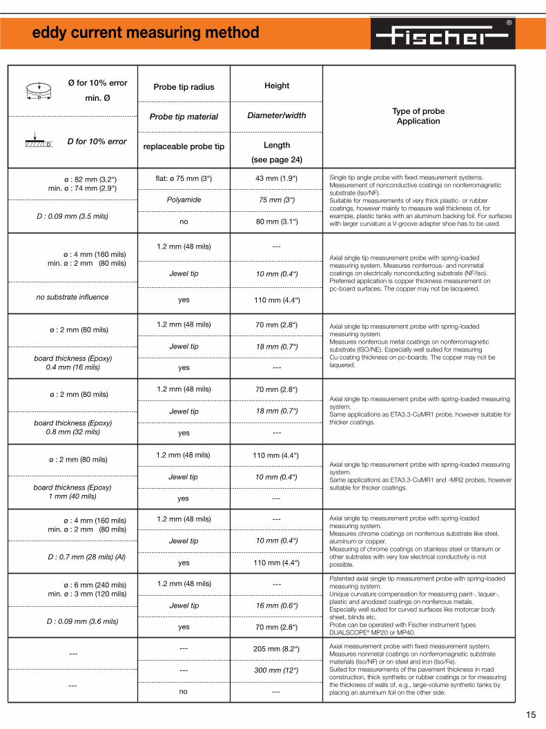

Characteristic values and technical data of probes for the phase-sensitive eddy current measurement method
Characteristic values and technical data of probes for the modified eddy current measuring method
Ø for 10% error
min. Øø
Measurement point
Ø for 10% error
min. Ø
ø
ø
D
16 17
ø : 15 mm (600 mils) (NF/Fe)min. ø : 1 mm (40 mils) (NF/Fe)
ø : 75 mm (3“) (Iso/NF)min. ø : 1 mm (40 mils) (Iso/NF)
ø : 30 mm (1.2“) (NF/Fe)min. ø : 15 mm (600 mils) (NF/Fe)
ø : 75 mm (3“) (Iso/NF)min. ø : 15 mm (600 mils) (Iso/NF)
Note: Electrical conductivity changes of the base material in the range between 17 MS/m and 58 MS/m (30-100% IACS) cause a measurement error of < 2% with all eddy current probes listed in the tables.
ED10602-796
ED10L602-093
NF/Fe0-50 µm : 0.2 µm (0.008 mil) 50-1500 µm (0-60 mils) : 1 %
Iso/NF0-100 µm : 0.5 µm (0.02 mil)
100-1200 µm (4-48 mils) : 0.5 %
NF/Fe0-50 µm : 0.1 µm (0.004 mil)
50-1500 µm (2-60 mils) : 0.5 % Iso/NF
0-100 µm : 0.2 µm (0.008 mil)100-1200 µm : 0.5 %
Dual Mode0-800 µm (0-32 mils) (NE/Fe)0-800 µm (0-32 mils) (Iso/NE)
Single Mode0-1500 µm (0-60 mils) (NE/Fe)0-1200 µm (0-48 mils) (Iso/Fe)
Measurementrange
DescriptionOrder Number
Measurementaccuracy*
us
Measurementprecision*
s
ø : 13 mm (520 mils) (NF/Fe)min. ø : 1 mm (40 mils) (NF/Fe)
ø : 45 mm (1.8“) (Iso/NF)min. ø : 1 mm (40 mils) (Iso/NF)
ø : 30 mm (1.2“) (NF/Fe)min. ø : 15 mm (600 mils) (NF/Fe)
ø : 45 mm (1.8“) (Iso/Fe)min. ø : 15 mm (600 mils) (Iso/Fe)
NF/FeZn 15-30 µm (0.6-1.2 mils) : 15 %
Zn ≥ 30 µm (1.2 mils) : 5 % Iso/NF
Paint 0-50 µm (2 mils) : 5 % Paint ≥ 50 µm (2 mils) : 1 %
NF/FeZn 15-30 µm (0.6-1.2 mils) : 0.6 µm
Zn ≥ 30 µm (1.2 mils) : 2 % Iso/Fe
Paint ≤ 1.5 µm (0.06 mil)
EDX10603-084
0 - 800 µm (32 mils)
Total paint + Zn (NF/Fe)or only paint (paint/Fe)
Note regarding probe designations:
L: cable length for magnetic induction probes 5 mand for eddy current probes 3 m instead of 1.5 m.
F: Measuring element protected against moist,aggressive media.
T: Intermittent measurements on specimens withtemperatures up to 100 ºC (212 ºF) possible.
* Note: Probe capability (accuracy and precision)tested under controlled conditions.
h : 0-700 µm (0-28 mils) (NF/Fe)
h : 0-200 µm (0-8 mils) (Ni/Fe)
ø 10%: 4 mm/2 mm (160/80 mils)at 25 µm (1 mil) Zn/Fe
min ø: 4 mm/2 mm (160 mils/80 mils) at 25 µm (1 mil) Ni/Fe
h : 0-700 µm (0-28 mils) (NF/Fe)
h : 0-200 µm (0-8 mils) (Ni/Fe)
ø 10%: 4 mm/2 mm (160/80 mils)at 25 µm (1 mil) Zn/Fe
min ø: 4 mm/2 mm (160 mils/80 mils) at 25 µm (1 mil) Ni/Fe
0-500 µm (0-20 mils) (Zn/Fe)0-180 µm (0-7.2 mils) (Cu/Fe)
0-100 µm (0-4 mils) (Ni/Fe)
0.04 µm (0.0016 mils) or 1 % (Zn/Fe)
0.1 µm (0.004 mils) or 2 % Ni/Fe)
ESD2602-308
0-200 µm (0-8 mils) (Zn/Fe)0-80 µm 80-3.2 mils) (Cu/Fe)
0-50 µm (0-2 mils) (Ni/Fe)
0.02 µm (0.008 mils) or 0.5 % (Zn/Fe)
0.05 µm (0.002 mils) or 1 % (Ni/Fe)
ESD1(1)
ESD1L(1)
602-307
602-898
Index description see page 22.
Lift-off hConvex curvature
Description/No.us*
s*
NF/FeEdge effect: 0.5 mm (20 mils)
Min. ø : 2 mm (28 mils)
Iso/FeEdge effect: 0.7 mm
Min. ø : 2 mm (28 mils)
NF/Feø : 0.4 mm (16 mils)
Iso/Fe
depending on the normalization layer
0.75 mm (30 mils)
Tungsten carbide
100 mm (4“)
---
13 mm (0.5“)
Axial measurement probe for simultaneous measurement ofindividual coating thicknesses of duplex coatings (paint/zinc) onsteel sheets (e.g., in household appliance manufacturing) or onsteel constructions in structural metal engineering.Both electro-galvanized and hot galvanized coatings can bemeasured.Probe can be connected to measuring instrument modelsDUALSCOPE® MP20 and MP40.
ø :12 mm (480 mils) (NF/Fe)min. ø : 2 mm (80 mils) (NF/Fe)
ø : 4 mm (160 mils) (Iso/NF)min. ø : 2 mm (80 mils) (Iso/NF)
D : 0.2 mm (8 mils) (NF/Fe)
D : 0.09 mm (4 mils) (Iso/NF)
Tungsten carbide
no 100 mm (4“)
---
13 mm (0.5“)
Axial measurement probe for simultaneous measurement ofindividual coating thicknesses according to the magnetic inductionmethod and eddy current method. Especially well suited for measuring paint- and laquer thicknesseson steel or iron or aluminum or copper etc. Because of smallprobe tip not suited for measuring on rough e.g. shot-blastedsurfaces.Both electro-galvanized and hot galvanized coatings can bemeasured.Probe can be connected to instrument models DUALSCOPE®
MP10/20/30/40 (depending on the measuring method) andFISCHERSCOPE® MMS® module PERMASCOPE®.
Type of probeApplication
Probe tip radius
Probe tip material
replaceable probe tip
Ø for 10% error
min. Ø
D for 10% error
Height
Diameter/width
Length
(see page 24)
no
0.75 mm (30 mils)
6 mm/2 mm (240/80 mils)at 25 µm (1 mil) Zn/Fe
6 mm/2 mm (240/80 mils)at 25 µm (1 mil) Ni/Fe
6 mm/4 mm (240/160 mils)at 25 µm (1 mil) Zn/Fe
6 mm/4 mm (240/160 mils)at 25 µm (1 mil) Ni/Fe
0.1 mm (4 mils)
0.1 mm (4 mils)
0.1 mm (4 mils)
0.1 mm (4 mils)
flat: ø 5.5 mm (220 mils)
Polyamide
no
---
16 mm (0.6“)
110 mm (4.3“)
flat: ø 5.5 mm (220 mils)
Polyamide
no
---
16 mm (0.6“)
110 mm (4.3“)
Measurement of nonferrous metal coatings on steel and iron(NF/Fe) or nonferrous metal coatings on nonferrous substrates(NF/NF), as well as electroplated nickel coatings on steel (Ni/Fe).Suited especially for fast, non-destructive measurement of nickelcoatings. Produces very little measurement scatter when mea-suring NF-coatings on very rough steel surfaces. Measurement ofNF-coatings on NF-substrate if the electrical conductivity of thecoating material is at least double the conductivity of the substratematerial. Due to lift-off compensation of the test signal it is possibleto perform noncontacting measurements or measurements ofcoatings under a nonconductive coating up to 700 µm (28 mils)(for Ni up to 200 µm (8 mils)) thickness. The measurement systemis moisture proof.
Axial single tip measurement probe with spring-loaded measuringelement. Measures nonferrous metal coatings on steel or iron (NF/Fe) or onnonferrous metal coatings (NF/NF) and galvanized nickel coatingson steel or iron (Ni/Fe).Same applications and characteristics as ESD1 probe, howeversuitable for thinner coatings. As with probes ESD1 and ESD3 verylittle influence from test area geometry.
Type of probeApplication
Probe tip radiusProbe tip material
replaceable probe tip
HeightDiameter/width
Length (see page 24)
Ø for 10% errorD for 10% error
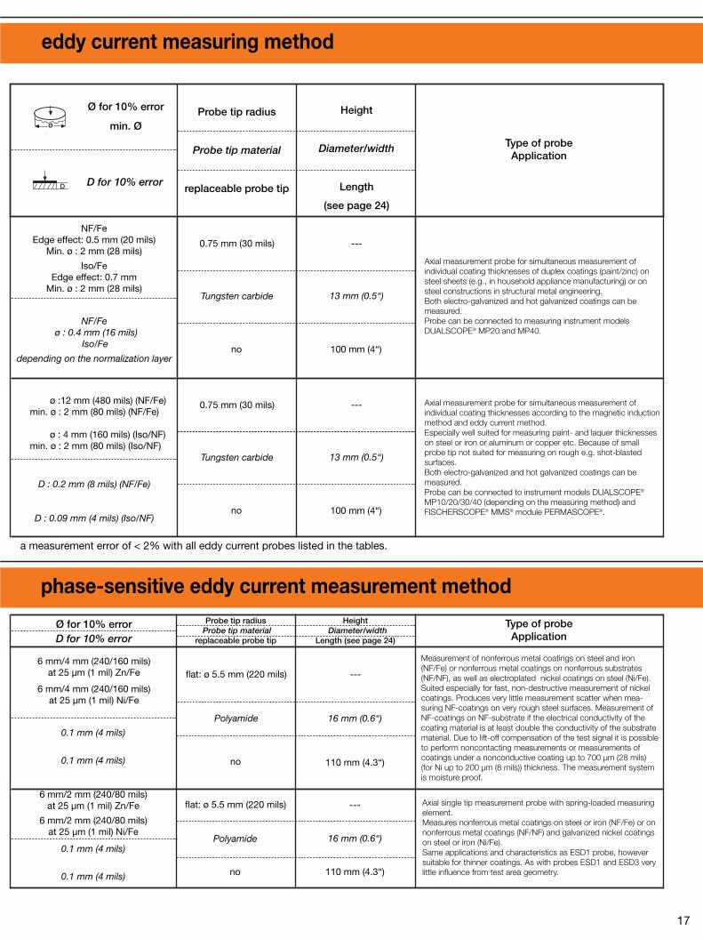

®
Characteristic values and technical data of probes for the phase- sensitive eddy current measurement method
Lift-off hø
Dø
Measurement point
h
Probe
Coating
Ø for
10% error/min. Ø
18 19
0.3 µm or 1 %
DescriptionOrder Number
Measurementrange
Measurementprecision*
s
ESL08A(1)
602-224
ESC3(1)
603-039
5 - 80 µm (Cu/Iso)
only for measurements in boreholeswith 0.8 to 2.0 mm (32 to 80 mils)
diameter
Lift-off compensationfor bore diameters of
0.8 - 1.8 mm (32 to 70 mils)
Lift-off compensationfor bore diameters of
0.8 - 1.8 mm (32 to 70 mils)
only for measurements in boreholeswith 0.8 to 2.0 mm (32 to 80 mils)
diameter
no lift-off compensation
0.3 µm or 1 %
SL08A(6)
602-385
5 - 80 µm (Cu/Iso)
1 - 800 µm (paint/Zn)1 - 100 µm (Zn/Fe)
1 µm or 1 % (paint/Zn)1 µm or 1 % (Zn/Fe)
ø : 20 mm (800 mils) (paint/Zn)ø : 6 mm (240 mils) (Zn/Fe)
ESG2(7)
ESG2L(7)
602-311602-724
h : 0 - 300 µm (12 mils)no lift-off compensation
h : 0 - 300 µm (12 mils)no lift-off compensation
6 mm/3 mm (240/120 mils)at 100 µm (4 mils) Cu/Iso
35 mm/2 mm (1400/80 mils)at 230 µm (9 mils) Cr/Al
6 mm/3 mm (240/120 mils)35 mm/2 mm (1400/80 mils)
at 150 µm (6 mils) Cr/Al
ESC1(1)
602-658
0 - 170 µm (Cu/Iso) 0 - 700 µm (Cr/Cu)
0 - 90 µm (Cu/Iso)0 - 200 µm (Cr/Cu)
ESC2602-237
0.04 µm or 1 % (Cu/Iso)0.1 µm or 2 % (Cr/Cu)
0.02 µm or 0.5 % (Cu/Iso)0.05 µm or 1 % (Cr/Cu)
0 - 700 µm (28 mils)
22 mm/6 mm (870/240 mils)at 200 µm (8 mils) Cu/Fe
ESD3(1)
602-309
0 - 2000 µm (Zn/Fe) 0 - 1000 µm (Cu/Fe)
90 - 1000 µm (Cu/Iso) 0 - 500 µm (0 - 20 mils)
0.2 µm or 0.5 % (Cu/Fe)
0.3 µm/0.5 % not relevant
Index description see page 22.
Note regarding probe designations:
L: cable length for magnetic induction probes 5 mand for eddy current probes 3 m instead of 1.5 m.
F: Measuring element protected against moist,aggressive media.
T: Intermittent measurements on specimens withtemperatures up to 100 ºC (212 ºF) possible.
* Note: Probe capability (accuracy and precision)tested under controlled conditions. (the greater value applies)
0.2 mm (8 mils) Fe
not relevant
board thickness from D = 0.5 mm (20 mils) to 2.5 mm (100 mils)
can be entered
not relevant
board thickness from D = 0.5 mm (20 mils) to 2.5 mm (100 mils)
can be entered
10 mm/4 mm (400/160 mils)
Type of probeApplication
Probe tip radius
Probe tip material
replaceable probe tip
ø Probe tip: 0.78 mm(31 mils)
ø Probe tip: 0.78 mm(31 mils)
Austenitic steel
no
---
13 mm (0.5“)
100 mm (4“)
Austenitic steel
no
---
13 mm (0.5“)
100 mm (4“)
ø Probe tip: 0.78 mm(31 mils)
Austenitic steel
no
---
20 mm (0.8“)
100 mm (4“)
Height
Diameter/width
Length
(see page 24)
Single tip axial probe for inside measurements with fixedmeasurement system.Designed specifically to measure the thickness of copper plating (even under a Sn- or SnPb-coating ) in metallized through holes of PC-boards. Smallest permissible PTH diameter: 0.8 mm (32 mils).
Single pole probe for inside measurements with fixed measurement system.Same as ESL08A probe, however used only for CU-SCOPE CMP1A.
Axial single tip probe with spring-loaded measuring system.Simultaneous measurement of a double coating, i.e. paint overzinc on steel.Suitable to measure so-called Duplex coatings (paint over zinc and zinc alloy on galvanized surfaces) on sheet metal or strips. Not suitable for thick, hot dipped galvanized coatings, because ofthe nonhomogeneous alloy composition with unknown materialproperties and characteristics.
D for 10% error
Ø for
10% error/min. Ø
15 mm/10 mm (0.6/0.4“)at 200 µm (8 mils) Cu/Fe
0.2 mm (8 mils)
15 mm (600 mils)
not relevant
flat: ø 15 mm (600 mils)
Polyamide
no
no tip, flat: ø 15 mm (600 mils)
Polyamide
no
---
35 mm (1.4“)
130 mm (5.2“)
130 mm (5.2“)
18 mm (0.7“)
---
Measures nonferrous metal coatings on steel or iron (NF/Fe) ornonferrous metal coatings (NF/NF).Same applications (except Ni/Fe) and characteristics as ESD1probe, however suitable for thicker coatings.
Axial single tip measurement probe with spring-loaded measuringelement. Measures nonferrous metal coatings on nonmetal (NF/Iso) or onnonferrous metal substrate materials (NF/NF).Same applications as ESC1 probe, but for thicker coatings.
8 mm/6 mm (320/240 mils)at 100 µm (4 mils) Cu/Iso
10 mm/6 mm (400/240 mils)at 230 µm (9 mils) Cr/Al
8 mm/4 mm (320/160 mils) at 60 µm (2.4 mils) Cu/Iso
10 mm/4 mm (400/160 mils)at 150 µm (6 mils) Cr/Al
---0.9 mm (35 mils) CuZn
---0.5 mm (20 mils) CuZn
flat: ø 5.5 mm (220 mils)
Polyamide
no
---
16 mm (0.63“)
110 mm (4.3“)
flat: ø 5.5 mm (220 mils)
Polyamide
no
---
16 mm (0.63“)
Measurement of nonferrous metal coatings on nonconductivesubstrates (NF/NC) and nonferrous metal substrates (NF/NF).
Main application is to measure Cu-cladding thickness onPC-boards, also under a conformal coating; also measures thethickness of metal foils, as well as Cr-coatings on copper,aluminum or brass.
Same application as ESC1 probe, however for thinner coatings.
110 mm (4.3“)
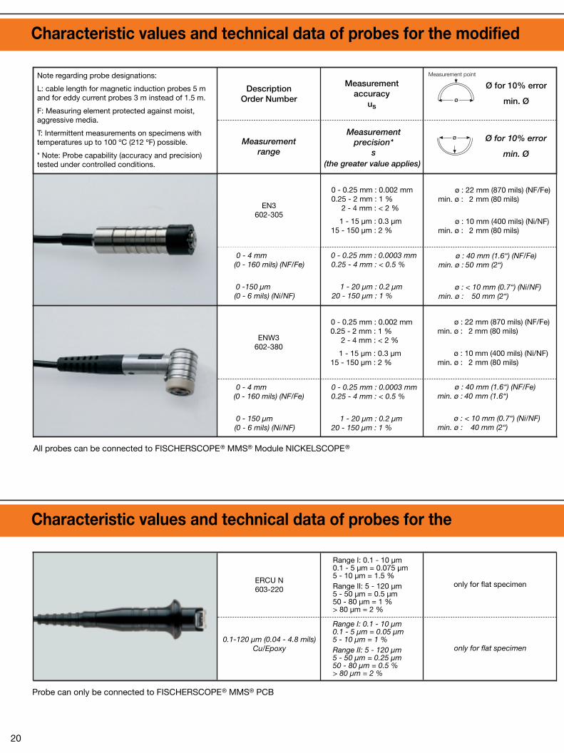
®
Characteristic values and technical data of probes for the modified magnetic method
ø
D
Ø for 10% error
min. Ø
Ø for 10% error
min. Ø
ø
ø
Measurement point
Characteristic values and technical data of probes for the electrical conductivity method
20 21
ø : 22 mm (870 mils) (NF/Fe) min. ø : 2 mm (80 mils)
ø : 10 mm (400 mils) (Ni/NF) min. ø : 2 mm (80 mils)
ø : 40 mm (1.6“) (NF/Fe) min. ø : 50 mm (2“)
ø : < 10 mm (0.7“) (Ni/NF) min. ø : 50 mm (2“)
EN3602-305
0 - 0.25 mm : 0.002 mm0.25 - 2 mm : 1 %
2 - 4 mm : < 2 %
1 - 15 µm : 0.3 µm15 - 150 µm : 2 %
0 - 0.25 mm : 0.0003 mm0.25 - 4 mm : < 0.5 %
1 - 20 µm : 0.2 µm20 - 150 µm : 1 %
0 - 4 mm (0 - 160 mils) (NF/Fe)
0 -150 µm (0 - 6 mils) (Ni/NF)
ø : 22 mm (870 mils) (NF/Fe) min. ø : 2 mm (80 mils)
ø : 10 mm (400 mils) (Ni/NF) min. ø : 2 mm (80 mils)
ø : 40 mm (1.6“) (NF/Fe) min. ø : 40 mm (1.6“)
ø : < 10 mm (0.7“) (Ni/NF) min. ø : 40 mm (2“)
ENW3602-380
0 - 0.25 mm : 0.002 mm0.25 - 2 mm : 1 %
2 - 4 mm : < 2 %
1 - 15 µm : 0.3 µm15 - 150 µm : 2 %
0 - 0.25 mm : 0.0003 mm0.25 - 4 mm : < 0.5 %
1 - 20 µm : 0.2 µm20 - 150 µm : 1 %
Range I: 0.1 - 10 µm0.1 - 5 µm = 0.075 µm5 - 10 µm = 1.5 %Range II: 5 - 120 µm5 - 50 µm = 0.5 µm50 - 80 µm = 1 % > 80 µm = 2 %
Range I: 0.1 - 10 µm0.1 - 5 µm = 0.05 µm5 - 10 µm = 1 %Range II: 5 - 120 µm5 - 50 µm = 0.25 µm50 - 80 µm = 0.5 %> 80 µm = 2 %
only for flat specimen
only for flat specimen
0 - 4 mm (0 - 160 mils) (NF/Fe)
0 - 150 µm (0 - 6 mils) (Ni/NF)
ERCU N603-220
0.1-120 µm (0.04 - 4.8 mils)Cu/Epoxy
Measurementaccuracy
us
DescriptionOrder Number
Measurementrange
All probes can be connected to FISCHERSCOPE® MMS® Module NICKELSCOPE®
Probe can only be connected to FISCHERSCOPE® MMS® PCB
Measurementprecision*
s(the greater value applies)
Note regarding probe designations:
L: cable length for magnetic induction probes 5 mand for eddy current probes 3 m instead of 1.5 m.
F: Measuring element protected against moist,aggressive media.
T: Intermittent measurements on specimens withtemperatures up to 100 ºC (212 ºF) possible.
* Note: Probe capability (accuracy and precision)tested under controlled conditions.
ø : 22 mm (870 mils)min. ø : 2 mm (80 mils)
ø : 8 mm (320 mils) min. ø : 2 mm (80 mils)
D : 0.1 mm (4 mils)
not relevant (Ni/NF)
D : 0.1 mm (4 mils)
not relevant (Ni/NF)
ø : 22 mm (870 mils)min. ø : 2 mm (80 mils)
ø : 8 mm (320 mils) min. ø : 2 mm (80 mils)
not relevant
: 8 x 8 mm
: 1 mm
Ø for 10% error
min. Ø
D for 10% error
Type of probeApplication
Probe tip radius
Probe tip material
replaceable probe tip
flat: 0.75 mm (30 mils)
Heat treated steel
no
---
13 mm (0.5“)
80 mm (3.1“)
flat: 0.75 mm (30 mils)
Heat treated steel
no
50 µm (2 mils)
Heat treated steel
no
130 mm (5“)
32 mm (1.2“)
---
23 mm (0.9“)
14 mm (0.6“)
72 mm (2.8“)
Height
Diameter/width
Length
(see page 24)
Axial single tip probe with spring-loaded measuring system.
Measurement of nonferrous metal coatings on steel and iron(NF/Fe) or electroplated nickel coatings on nonferrous substrates(Ni/NF).
Ideally suited for the measurement of electroplated nickel coatingson, for example: PC-board contacts, also under a thin coating ofgold. Also used to measure thick NF metal coatings on steel, notsubject to eddy current induced measurement errors in thickconductive coatings.
Single tip angle probe with spring-loaded measuring system.
Same as probe EN3, however designed for measurements inpipes, bore holes or recesses.
Four-point probe measuring copper coating thicknesses on the surface of printed circuit boards according to the electricresistance method. No interference from underlying coppercoatings separated by thin isolating layers.
min.
(320 x 320 mils)
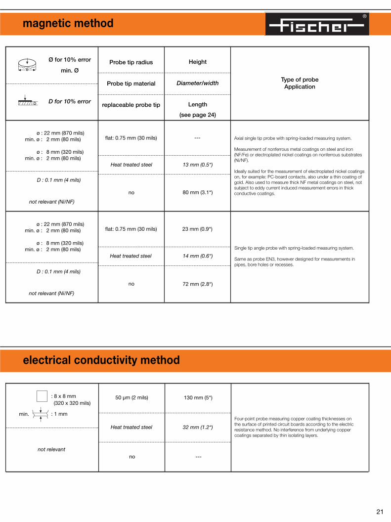

®
Characteristic values and technical data of probes to measure the electrical volume conductivity
ø
D
h
ø
22 23
0 - 500 µm (20 mils)
36 mm (1400 mils)2 mm (80 mils)
0 - 700 µm (28 mils)
50 mm (200 mils)2 mm (80 mils)
0 - 700 µm (28 mils)
50 mm (200 mils)2 mm (80 mils)
ES1A(1)
602-222
0.5 - 108 % IACS0.3 - 63 MS/m
Measurementrange
DescriptionOrder Number
Measurementaccuracy*
us
Lift-off h
Ø for 10% error
min. Ø
0.3 %of measured value
0.01 % IACS or0.03 % of measured value
ESW1A(1)
602-389
0.5 - 108 % IACS0.3 - 63 MS/m
0.3 %of measured value
0.01 % IACS or0.03 % of measured value
ES2602-223
0.5 - 108 % IACS0.3 - 63 MS/m
0.5 %of measured value
0.0 1% IACS or0.05 % of measured value
0 - 700 µm (28 mils)
50 mm (200 mils)2 mm (80 mils)
S1A (2)
601-568
0.5 - 108% IACS0.3 - 63 MS/m
0.3 %of measured value
0.01 % IACS or0.03 % of measured value
0 - 700 µm (28 mils)
50 mm (200 mils)2 mm (80 mils)
SW1A (2)
601-615
0.5 - 108% IACS0.3 - 63 MS/m
0.3 %of measured value
0.01 % IACS or0.03 % of measured value
0 - 500 µm (20 mils)
36 mm (1400 mils)2 mm (80 mils)
S2 (3)
601-569
0.5 - 108% IACS0.3 - 63 MS/m
0.5 %of measured value
0.01 % IACS or0.05 % of measured value
0 - 500 µm (20 mils)
30 mm (1.2“)1 mm (40 mils)
ES4B (4)
602-539ES40(5)
603-235
0,5-108 % IACS0,3-63 MS/m
0,3 %of measured value
0,01 % IACS or0,03 % of measured value
(1) : Probe can only be connected to FISCHERSCOPE® MMS® module SIGMASCOPE® and module DUPLEX(2) : Probe can only be connected to SIGMASCOPE® SMP1B(3) : Probe can only be connected to SIGMASCOPE® SMP2(4) : Probe can only be connected to FISCHERSCOPE® MMS® EURO HF
(5) : Probe can only be connected to SIGMASCOPE® SMP10(6) : Probe can only be connected to CU-SCOPE® CMP1A(7) : Probe can only be connected to FISCHERSCOPE® MMS Module DUPLEX
Probe
Coating
Measurement pointMeasurementprecision*
s
Note regarding probe designations:
L: cable length for magnetic induction probes 5 mand for eddy current probes 3 m instead of 1.5 m.
F: Measuring element protected against moist,aggressive media.
T: Intermittent measurements on specimens withtemperatures up to 100 ºC (212 ºF) possible.
* Note: Probe capability (accuracy and precision)tested under controlled conditions.
12 mm (470 mils)5 mm (200 mils)
0.44 mm (17 mils)at 52% IACS
22 mm (870 mils)15 mm (590 mils)
0.91 mm (36 mils)at 52% IACS
22 mm (870 mils)15 mm (590 mils)
0.91 mm (36 mils)at 52% IACS
Ø for 10% error
min. Ø
D for 10% error
Type of probeApplication
Probe tip radius
Probe tip material
replaceable probe tip
22 mm (870 mils)15 mm (590 mils)
0.91 mm (36 mils)at 52% IACS
22 mm (870 mils)15 mm (590 mils)
0.91 mm (36 mils)at 52% IACS
12 mm (470 mils)5 mm (200 mils)
0.44 mm (17 mils)at 52% IACS
flat: ø 14 mm (550 mils)
Polyamide
no
---
35 mm (1.4“)
130 mm (5.1“)
flat: ø 14 mm (550 mils)
Polyamide
no
40 mm (1.6“)
35 mm (1.4“)
90 mm (3.5“)
flat: ø 5.5 mm (220 mils)
Polyamide
no
---
---
110 mm (4.3“)
flat: ø 14 mm (550 mils)
Polyamide
no
---
18 mm (0.7“)
130 mm (5.1“)
flat: ø 14 mm (550 mils)
Polyamide
no
40 mm (1.6“)
35 mm (1.4“)
90 mm (3.5“)
flat: ø 5.5 mm (220 mils)
Polyamide
no
---
16 mm (0.6“)
110 mm (4.3“)
10 mm (400 mils)5 mm (200 mils)
0.35 mmat 30 MS/m and 480 kHz
flat: ø 14 mm (550 mils)
Polyamide
no
---
18 mm (0.7“)
90 mm (3.5“)
Height
Diameter/width
Length
(see page 24)
Axial single tip probe with fixed measurement system.Used to measure volume conductivity of nonferrous metals.Used mainly in the aerospace industry, for NF-metal testing orprocessing. Also suitable to check heat treatment effects (materialstrength) or to check for microstructural changes. A separate V-groove adapter has to be used on curved surfaces.
Single tip angle probe with fixed measurement system. Same application as ES1A probe, however designed formeasurements in pipes, bore holes or recesses. A separate V-groove adapter has to be used on curved surfaces.
Axial single tip probe with fixed measurement system.Same application as ES1A probe, however due to the highermeasurement frequency especially suited for thinner specimen(strips, sheet metal, coatings).
Axial single tip probe with fixed measurement system.Same application as ES1A probe, however only in conjunctionwith the hand-held instruments SMP1B and SMP1BS.
Single tip angle probe with fixed measurement system.Same application as S1A probe, however designed formeasurements in pipes, bore holes and recesses.
Axial single tip probe with fixed measurement system.Same application as ES2 probe, however only in conjunction with the hand-held instrument SMP2.
Axial single-tip measurement probe with fixed measuring element.Measures the electrical conductivity of nonferrous metalsaccording to the eddy current method. Applications include mate-rial sorting, heat treatment inspections and analysis of structuralconditions. Suitable for the following measurement frequencies:120 kHz, 240 kHz and 480 kHz.Measurement ES40 probe is additionally suited for a frequency of60 kHz and contains an integrated temperature sensor.
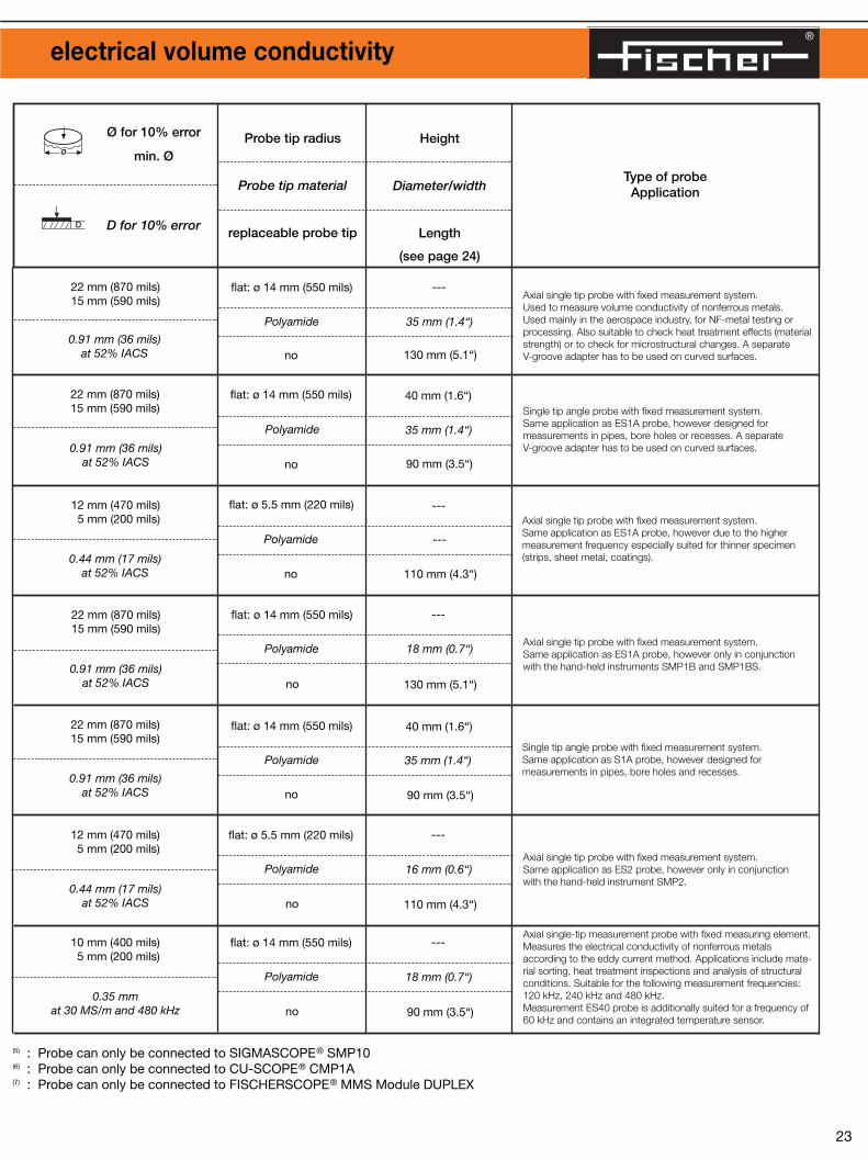

Characteristic values and technical data of probes to measure the ferrite content
ø
ø
ø
D
24 25
ø : 15 mm (590 mils)min. ø : 1 mm (80 mils)
ø : 30 mm (1.2“)min. ø : 10 mm (400 mils)
EGAB1.3-FE602-221
0.1 - 80 % Fe0.1 - 110 FN
0 - 5 %Fe/5FN : 0.1 %FE/FN5 %Fe/5FN - 80 %/110FN : 2 %
0 - 10 %Fe/10FN : 0.05 %Fe/FN10 %Fe/10FN - 80 %Fe/110FN : 0.5 %
ø : 15 mm (590 mils)min. ø : 1 mm (40 mils)
ø : 36 mm (1.4“)min. ø : 18 mm (720 mils)
EGABW1.3-FE602-304
EGABW1.3L-FE602-614
0.1 - 80 % Fe0.1 - 110 FN
0 - 5 %Fe/5FN : 0.1 %FE/FN5 %Fe/5FN - 80 %/110FN : 2 %
0 - 10 %Fe/10FN : 0.05 %Fe/FN10 %Fe/10FN - 80 %Fe/110FN : 0.5 %
ø : 15 mm (590 mils)min. ø : 2 mm (80 mils)
ø : 30 mm (1.2“)min. ø : 9 mm (350 mils)
EGABI1.3-150FE602-706
0.1 - 80% Fe0.1 - 110 FN
0 - 10 %Fe/10FN : 0.05 %Fe/FN10 %Fe/10FN - 68 %Fe/110FN : 0.5 %
0 - 5 %Fe/5FN : 0.1 %FE/FN5 %Fe/5FN - 80 %/110FN : 2 %
Measurementrange
DescriptionOrder Number
Measurementaccuracy*
us
Measurementprecision*
s
Ø for 5% error
min. Ø
Ø for 5% error
min. Ø
All probes can be connected to FISCHERSCOPE® MMS® module PERMASCOPE® and FERITSCOPE® MP30(1) : Measurement of Delta Ferrite content in sheet material. Thickness of the sheet material.(2) : Measurement of Delta Ferrite content in clad layers. Thickness of the cladding.
Measurement point
Comments to probe dimensions:
Listed are the maximum diameter (respective to width) and the maximum height of theprobe, as well as the overall length from the probe tip to the cable entry point.
Length Length
Example EGAB1.3 Example EGABW1.3
DiameterHeight
Diameter
Note regarding probe designations:
L: cable length for magnetic induction probes 5 mand for eddy current probes 3 m instead of 1.5 m.
F: Measuring element protected against moist,aggressive media.
T: Intermittent measurements on specimens withtemperatures up to 100 ºC (212 ºF) possible.
* Note: Probe capability (accuracy and precision)tested under controlled conditions.
ø : 10 mm (400 mils)min. ø : 2 mm (80 mils)
D : 1 mm (40 mils)D : 1 mm (40 mils)
ø : 10 mm (400 mils)min. ø : 2 mm (80 mils)
D : 1 mm (40 mils)D : 1 mm (40 mils)
ø : 10 mm (400 mils)min. ø : 2 mm (80 mils)
D : 1 mm (40 mils)D : 1 mm (40 mils)
Ø for 5% error
min. Ø
D for 5% error*
D for 10% error**
Type of probeApplication
Probe tip radius
Probe tip material
replaceable probe tip
0.75 mm (30 mils)
PVD coated
yes
---
10 mm (0.4“)
110 mm (4.3“)
0.75 mm (30 mils)
PVD coated
yes
23 mm (0.9“)
14 mm (0.6“)
72 mm (2.8“)
0.75 mm (30 mils)
PVD coated
yes
6.5 mm (0.26“)
5.5 mm (0.22“)
320 mm (12.6“)
Height
Diameter/width
Length
(see page 24)
Axial single tip probe with spring-loaded measuring system.Measurement of the Delta Ferrite content in ferrite percent or WRC ferrite number.Suitable for the measurement of delta ferrite content in weld metal and clad layers of austenitic or Duplex stainless steel. Also used to determine the ratio of martensite in austeniticstainless steels.
Single pole angle probe with spring-loaded measuring system.Same application as EGAB1.3-FE probe, however preferred formeasurements in pipes, bore holes or recesses.
Single tip probe for inside measurements with spring-loadedmeasuring system.Same application as EGAB1.3-FE probe, however designed formeasurements in pipes, bore holes and grooves. Externally triggered measurement acquisition should be usedwhen measuring small inside diameters to prevent measurementerrors.Maximum insertion depth : 320 mm (12.8“).
Example EKB25 Example V1EGA1HR34Width
Length Length
HeightHeight
Width
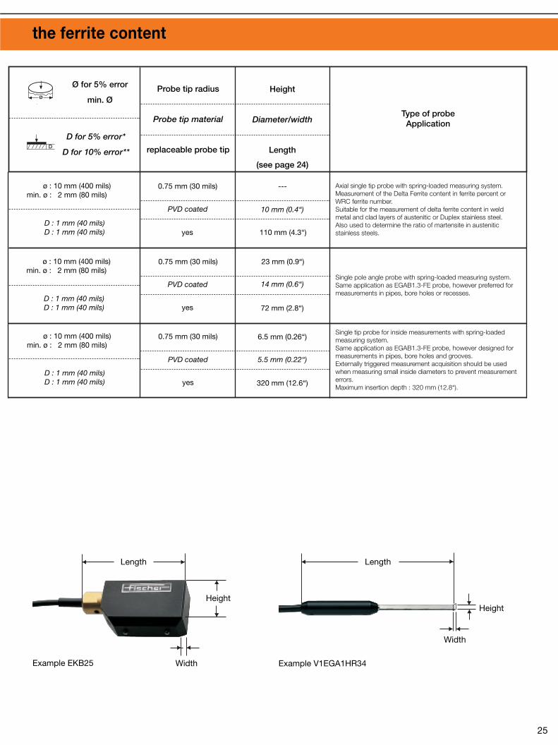

®
Test InstrumentsAccessories
26 27
V12 measurement stand with adapter600-213 to mount the following probes:• ESD1, ESD2• ESC1, ESC2• ES2
V12 measurement stand with V-table*, adapter600-173* and adapter 601-691 to mount thefollowing probes:• EGABI1.3-150, EGABI1.3-260,
V1EKB4, V1EKB10, EGABI1.3-150FE• EAI3.3-150
V12 measurement stand with magnetic shuttletable 600-019 and adapter 600-173* to mount the following probes:• EGA2H• EN3
V12-SP measurement stand with quick loadingscrew fixture and adapter 602-370* to mountthe following probes:• EGAB1.3, EGB2, EGAB1.3FE
Screw measurement device for accuratemeasurements of coating thicknesses onmetallic fasteners according to ISO DIN 4042.
Measuring stand V12 mot. MP for automatedmeasurements specifically for paint coatingswithout indentation- or positioning errors.
Measuring head MD4 for automatic measure-ments of coatings on ferromagnetic substratematerials. Easy integration into production linesfor 100% testing.
For the accurate measurement of coating thickness on small parts,such as fasteners, stampings, sleeves, etc. or parts with complexgeometry. Probe specific mounting adapters are required.
*: included with standard V12 measurement stand (order number 602-260) or V12-SP stand (order number602-262)
V12 measurement stand with V-table*,adapter 600-173* and adapter 600-077 tomount the following probes:• EGABW1.3, EGBW2, EGABW1.3FE• EAW3.3, EA9• ENW3
V12 measurement stand with base* andadapter 600-796* to mount the followingprobes:• ETA3.3H, ETA3.3F, ETA3.3T• EGAB1.3-SD• V6EKB4
DELTASCOPE® MP10 displays individualmeasurement values without statistics, it has no serial interface (no printing, no data transfer)and does not store measurement values.
Measurement of the paint coating thickness ona curved surface using ETD3.3 probe andDUALSCOPE® MP40.
DUALSCOPE® MP20 with statistical measure-ment series evaluation capability. Does not storemeasurements, it has no serial interface.
Measurement of a duplex coating (paint/zinccoating on iron) using EDX10 probe andDUALSCOPE® MP40.
Hand-held NICKELSCOPE® NMP2 for themeasurement of nickel or nonferrous metalcoating on steel, as well as nonferrous metalcoatings on nonconductive substrates.
Measurement system Fischerscope® MMS withvarious methods for coating thickness mea-surement and material testing.
The CU-SCOPE CMP1A is used to measurecopper plating thickness in PCB through holes.
The FERITSCOPE® MP30 determines the deltaferrite content in austenitic weld metal or duplexstainless steel.
SIGMASCOPE® SMP10 for measuring theelectrical conductivity of nonferromagnetic,electrically conducting metals.
A series of hand-held and bench top instruments are available for the probeslisted. For magnetic induction based measurement the DELTASCOPE®
MPxC series is used, the ISOSCOPE® MP series is used for eddy current
coating thickness measurement, the DUALSCOPE® MP20 and MP40 seriescombine the magnetic induction and eddy current methods.

® ®
Active Around the World Probes and Measurement Fixtures
The Institute for Electronics and Measurement Technology
HELMUT FISCHER in Sindelfingen/Germany is
an innovative leader in the field of coatingthickness measure-
ment, material analysis, microhard-
ness testing, electricalconductivity- and
ferrite contentmeasurement as well
as for density and porosity testing.
The company is able torecommend the best solution for any appli-
cation. A compre-hensive range of
products is offered using X-ray fluores-cence; Beta-backscatter; Magnetic;Magnetic induction; Electric resistance; Eddy current and Coulometrictechniques. HELMUT FISCHER has 12 subsidiary
companies and 32 marketing agencies
strategically located around the globe.
FISCHERSCOPE® X-RAY to measure coatingthickness using the X-Ray fluorescence method.
The high quality standard of FISCHERinstruments is the result of our efforts toprovide the very best instrumentation toour customers.
FISCHER is a reliable and competentpartner, offering expert advice, extensiveservice, and training seminars.
Today, FISCHER instruments are usedsuccessfully in all technological fields ofindustry and research.
POROSCOPE® HV20 to test for pores and pinholesin nonconductive coatings.
Microhardness testing system FISCHERSCOPE® H100C.
Fischer Instrumentation (G.B.) Ltd.Lymington/Hampshire SO41 8JD, EnglandTel. (+44) 1590-683663, Fax (+44) 1590-684110Internet: http://www.fischergb.co.uk
Fischer Instruments, S.A.08018 Barcelona, SpainTel. (+34) 93 309 79 16, Fax (+34) 93 485 05 94E-Mail: [email protected]
Helmut Fischer Meettechniek B.V.5627 GB Eindhoven, The NetherlandsTel. (+31) 40 248 22 55, Fax (+31) 40 242 88 85E-Mail: [email protected]
Fischer Instruments K.K.Saitama-ken 340, JapanTel. (+81) 489 32 3621, Fax (+81) 489 32 3618E-Mail: [email protected]
Fischer Instrumentation (Far East) Ltd.Kwai Chung, N.T., Hong KongTel. (+852) 24 20 11 00, Fax (+852) 24 87 02 18E-Mail: [email protected]
Fischer Technology, Inc.Windsor, Ct. 06095, USATel. 860 683-0781, Fax 860 688-8496Internet: http://www.fischer-technology.com
Fischer Instrumentation (S) Pte Ltd.Singapore 118529, SingaporeTel. (+65) 276 67 76, Fax (+65) 276 76 67E-Mail: [email protected] Fischer Instrumentation Ltd.Shanghai 200437, P.R.C., ChinaTel. (+86) 21 6555 7455, Fax (+86) 21 6555 2441E-Mail: [email protected]
ISO 9001SQS RegistrationNo. 11899
Valid for Helmut Fischer AG and Branch Offices
Helmut Fischer GmbH+Co.KG71069 Sindelfingen, GermanyTel. (+49) 70 31 303-0, Fax (+49) 70 31 303-79Internet: http://www.Helmut-Fischer.com
Sole Agent for Helmut Fischer GmbH+Co.KG, Germany:
Helmut Fischer Elektronik und Messtechnik AGCH-6331 Hünenberg, SwitzerlandTel. (+41) 41 785 08 00, Fax (+41) 41 785 08 01E-Mail: [email protected]
Branch Offices of Helmut Fischer AG, Switzerland:
Fischer Instrumentation Electronique78180 Montigny le Bretonneux, FranceTel. (+33) (0) 1 30 58 00 58, Fax (+33) (0) 1 30 58 89 50E-Mail: [email protected]
Helmut Fischer S.R.L., Tecnica di Misura20128 Milano, ItalyTel. (+39) 02 255 26 26, Fax (+39) 02 257 00 39E-Mail: [email protected]
© Helmut Fischer GmbH+Co.KG Subjects to changes 902-052 Printed in Germany 03/02
01/0
1
Application Specific Probes The key to successful coating measurement
Probes are the most important compo-nent of systems used to measure coa-ting thickness with either magnetic, magnetic induction and eddy currentmethods. This is the reason significantefforts and resources are expended byFISCHER for the development and qua-lity control of probes.
• FISCHER probes are adapted and optimized for the application!This guarantees accurate and reliablemeasurement results.
• FISCHER probes are dependable and durable!The probes are long lasting and durable, even when measurements are to be per-formed which test their “wear resistance”.
• FISCHER probes are reliable!This is due to their advanced design, their careful assembly and use of high quality components.


![La protection contre i'auto incrimination au canada - mythe ou réalité [yves de montigny]](https://img.pdfslide.us/doc/110x75/549d52a2b47959bd318b49be/la-protection-contre-iauto-incrimination-au-canada-mythe-ou-realite-yves-de-montigny.jpg)