Embed Size (px)
Citation preview

APPLICATION OF ULTRASONIC GUIDED WAVE FOR STRUCTURAL HEALTH
MONITORING OF PIPELINE
MUKHLIS CHUA @ CHUA CHING KOK
A dissertation submitted in partial fulfilment of the
requirements for the award of the degree of
Doctor of Engineering (Process Plant Management)
Faculty of Chemical and Energy Engineering
Universiti Teknologi Malaysia
OCTOBER 2015

iii
DEDICATION
In the name of Allah, the Most Beneficent, the Most Merciful.
“ Glory be to you, we have no knowledge except what you have taught us. Verily, it
is You, the All-Knower, the All-Wise”
(Al-Baqarah: 32)
To my family,
Thank you for your prayers and support.

iv
ACKNOWLEDGEMENT
I would like to express my deepest appreciation to my friend and teacher,
Professor Dr Peter Cawley, of Imperial College, London for his encouragement,
guidance, views and ideas throughout all phases of my graduate study. Special
thanks to Professor Dr Ir Mohd Salman Leong for his ideas, support and editing of
the thesis. I would also like to thank Professor Ramlan bin Aziz for his support and
encouragement in this research study. At Huntsman Tioxide Malaysia, I would like
to thank Mr Ramu Kumar for being a great friend and believing in me.I would also
like to thank En Khairul Izham Bin Musa for being very patient in providing me with
valuable information of their various systems and En Ahmad Affan Bin Zainun for
agreeing to release the information. At GUL, I would like to thank Dr David Alleyne
and Ben Nooteboom for their guidance and very interesting discussions especially
during the three days that David spent with us in our field work. At TWI,
Cambridge, I would like to thank Professor Gan Tat-Hean and Dr Slim Soua for the
many discussions held at his office and their different NDT approaches in resolving
industrial problems. This graduate continual professional education in this advanced
stage of my life would not be possible if not for the constant encouragement and
support from Dato‟ Seri Professor Ir Dr Zaini Ujang, for which I am extremely
grateful. Finally, I deeply appreciate the enormous moral support given by my wife,
Kaniza and my children, Arman, Clara, Hana, Adam and Sarah during this education
journey. I thoroughly enjoyed it and this could not have happened without their love,
patience and constant encouragement especially during times when I thought that
this feat was impossible! Last but not least, I cannot thank my son, Chien An,
enough, for his constant proof reading of my work, for being my companion in my
GW training sessions and during the stressful field work. I could not have completed
this thesis without his support.

v
ABSTRACT
Corrosion and erosion in pipes are a major concern for the chemical
industries specifically during the transportation of corrosive chemicals in steel
pipes.Such problems can lead to potential unscheduled plant down time and
economic losses which can be in the order of USD500K per day. Conventional
ultrasonic thickness (UT) measurement is routinely used to quantify remaining wall
thickness of pipes. In most practical transportation pipeline situations, the test
surface is so large that apoint by point inspection of the entire surface is not feasible.
As a result, industries seek a more efficient method to detect defects on their
pipelines. In this work, the application of guided wave technology to address this
serious industrial problem was quantitatively assessed in terms of technical
capabilities, economic feasibility and suitability to be incorporated as part of the
industry risk based inspection programmes. The technical capabilities are
qualitatively and quantitatively assessed through nine performance objectives, which
were formulated to determine if it can be adopted in the industry. Through
laboratory study and field work at a paint pigment chemical manufacturing plant, it
was shown that guided wave successfully met all nine performance objectives. It was
demonstrated to be suitable for the detection of common defects such as pit and
patch corrosion in a 12 inch nominal pipe size (NPS) Schedule 60 sulphuric acid
pipeline.Key performance achievements found from this field study included a
maximum inspection range of 260m from a single test location and the capability of
detecting and monitoring growth of defect of up to 2% cross-sectional area loss.
Through the use of the Inspection Value Method, it was shown in the case of the
2.75km acid pipeline the use of guided wave with follow-up UT inspection can value
their system at a net present value (NPV) of RM0.9 million at the 25th year; in
comparison to NPV of - RM0.1 million (negative) as a result of using conventional
manual UT on its own.A new inspection procedure which incorporates the use of
guided wave along with other conventional NDT methods was proposed which
complied with API 579-1 Fitness for Service requirements.

vi
ABSTRAK
Karat dan hakisan dalam paip adalah menjadi salah satu masalah utama
dalam industri petrokimia khususnya dalam pengaliran bahan kimia yang boleh
menghakis paip keluli. Hakisan sedemikian boleh membawa kepada kerosakan
yang tidak diduga. Kerugian pendapatan boleh mencapai sehingga USD500K sehari.
Pengukuran konvensional ultrasonik (UT) kerap diguna sebagai kaedah untuk
mengesan ketebalan dinding paip. Secara praktikal, paip mempunyai permukaan
keseluruhan yang amat besar yang perlu di imbas yang menyebabkan ujian tidak
boleh dilaksanakan. Oleh itu, industri perlu kepada kaedah yang lebih efisien untuk
mengesan kecacatan pada saluran paip mereka. Dalam kerja ini, aplikasi teknologi
gelombang untuk menangani masalah serius industri ini telah dinilai secara
kuantitatif dari segi teknikal, kewangan dan kesesuaian untuk digabungkan sebagai
sebahagian daripada program pemeriksaan berasaskan risiko dalam industri.
Keupayaan teknikal dinilai secara kualitatif dan kuantitatif melalui sembilan objektif
prestasi, yang dicadangkan untuk menentukan sama ada ianya boleh diguna dalam
industri. Melalui kajian makmal dan tapak di sebuah kilang pembuatan cat kimia
pigmen, kaedah ini telah menunjukkan bahawa teknologi gelombang ini memenuhi
kesemua sembilan objektif prestasi. Ianya dibuktikan sesuai dalam pengesahan
kecacatan yang biasa dihadapi iaitu lubang dan tampalan kakisan pada 12 inci untuk
talian paip asid sulfurik. Pencapaian prestasi utama yang diperoleh daripada kajian
tapak dengan menggunakan gelombang pelaksanaan ini termasuklah keupayaan
mencapai pemeriksaan maksimum sepanjang 260m dengan keupayaan mengesan dan
memantau kecacatan sehingga 2% keratan rentas. Melalui penggunaan Nilai Kaedah
Pemeriksaan, dalam kes 2.75 km paip asid ini, menggabungkan kaedah teknologi
gelombang yang disusuli pemeriksaan UT boleh mencapai nilai bersih kini (NPV)
daripada RM0. 9 juta pada tahun ke-25; berbanding dengan NPV dari -RM0.1 juta
(negatif) hasil dengan penggunaan UT sahaja. Kaedah pemeriksaan baru yang
melibatkan penggunaan gelombang dengan kaedah konvensional NDT yang
dicadangkan ini mematuhi keperluan API 579-1 Fitness for- Service.

vii
TABLE OF CONTENTS
CHAPTER TITLE PAGE
DECLARATION ii
DEDICATION iii
ACKNOWLEDGEMENT iv
ABSTRACT v
ABSTRAK vi
TABLE OF CONTENTS vii
LIST OF TABLES xiii
LIST OF FIGURES xv
LIST OF ABBREVIATIONS xxvii
LIST OF APPENDICES xxviii
1 INTRODUCTION 1
1.1 Structural Health Monitoring of Pipeline 1
1.2 Guided Wave Ultrasonic Testing 1
1.3 Background Problem and Motivation 4
1.4 Importance of the Study 9
1.5 Problem Statements 11
1.6 Research Objectives 13
1.6.1 Industrial Objectives 13
1.6.2 Academic Objective 14
1.7 Scope and Limitations of the Study 14
1.8 Structure of this Dissertation 15
2 LITERATURE REVIEW 18
2.1 Overview 18
2.2 Background 19

viii
2.3 Early Developments 23
2.3.1 Defects Sensitivity and Identifying Non-
Axisymmetric Features 24
2.3.2 Mode Choice 29
2.3.3 Effect of Frequency 30
2.3.4 Crack Detection 31
2.3.5 Application of Guided Waves in Other Geometries 32
2.4 Current Routine Usage 32
2.4.1 Commercial Systems 32
2.4.2 Typical Application Areas 36
2.5 Limitations of the Technology 37
2.5.1 Difficult Features 37
2.5.2 Technology Improvements 42
2.5.3 Mechanisms of Attenuation 43
2.6 Inspection of Embedded Structures 44
2.6.1 Effect of Embedding on the Properties of the Guided
Waves 45
2.7 Testing Past Features 48
2.7.1 The Influence of Features on Guided Waves 49
2.7.2 Effect of Bends on the Properties of the Guided
Waves 50
2.8 Reflections from Corrosion and Cracks 52
2.8.1 Reflections from Corrosion and Cracks in Pipes 52
2.8.2 Defect Sizing 54
2.9 Structural Health Monitoring and Pipeline Integrity
Management System 56
2.10 Review of Best Practice in Pipeline Integrity Management 57
2.11 Review and Selection of Detection Methods 60
2.12 Conclusions 62
3 GUIDED WAVES – THEORETICAL BACKGROUND 65
3.1 Overview 65
3.2 Introduction 65
3.3 Equations of Motion in Isotropic Media 66

ix
3.4 Guided Waves in Unbounded Stress-Free Plates 69
3.4.1 The Solution for SH Waves 70
3.5 Guided Waves in Hollow Cylinders 74
3.5.1 Modal Properties 77
3.6 Relationship between Guided Waves in Plates and Pipes 79
3.6.1 Application of the Plate-Pipe Analogy to a Through
the Thickness Circular Hole 82
3.7 Choice of Excitation Modes and Frequency Range for
Inspection Purposes 84
3.8 Finite Element Simulation of Guided Waves 85
3.8.1 General Procedure for FE Modelling 87
3.9 Conclusion 88
4 METHODOLOGY 89
4.1 Overview 89
4.2 Research Methodology 91
4.2.1 Technology Acquisition and Familiarisation 91
4.2.2 Establishment of Performance Criteria 92
4.3 Wavemaker Pipe Screening System 94
4.3.1 Materials & Equipment 94
4.3.2 Preparations before Inspection 96
4.3.3 Data Collection 103
4.3.4 Analytical Tools 104
4.3.5 Orientation of Features (Axi-Symmetric) 105
4.3.6 Orientation of Features (Non Axi-Symmetric) 106
4.3.7 Defining Features of the Pipe System 107
4.3.8 Distance Amplitude Correction (DAC) Setting 108
4.4 Conclusion 109
5 INDUSTRIAL CASE STUDY 111
5.1 Overview 111
5.2 Case 1: Huntsman-Tioxide Malaysia (HTM) 111
5.3 Site Problem Identification 111

x
5.4 Laboratory Setup 1 (Axisymmetric) 113
5.4.1 Simulating “Pit and Patch Corrosion” on a 4” Pipe 113
5.4.2 Practical Representation of Localised (Pit) and
Uniform Corrosion (Patch) 115
5.5 Laboratory Setup 2 (Non-axisymmetric) 118
5.5.1 Simulating “Pit and Patch Corrosion” on a 4-inch
Pipe Bend 118
5.6 Pilot Study: 12-inch Schedule 60 Sulphuric Acid
Transportation Pipeline (3.4 km) 120
5.6.1 Test Point 1 - Near Pig Receiver (Range of 20m in
each Direction) 122
5.6.2 Test Point 2 - Tunnel Exit to Pig Receiver (Range of
130m in each Direction) 125
5.6.3 TP 3 - At the Tunnel Exit (Range of 45m in each
Direction) 126
5.7 Results & Discussion 129
5.7.1 Performance Criterion 129
5.7.2 Minimum Size of Sizing Defect & Capability of
Defect Growth Monitoring 129
5.7.3 Frequency Regime Selection 133
5.7.4 Bandwidth Selection 133
5.7.5 Selection to EFC (Enhanced Focussing and
Circumferential Resolution) Mode at the Localised
Defect Location 134
5.7.6 Stability of Signal Traces 137
5.7.7 Achievable Inspection Distance 139
5.7.8 Stability of Signal Traces and Durability of
Transducers 142
5.7.9 Improved Planning for Maintenance Activities 144
5.7.10 Increased Efficiency in Pipeline Maintenance 146
5.7.11 Technology Maturation 147
5.8 Plant Wide Implementation 147
5.8.1 Introduction 147
5.8.2 Probability of Defect Detection Using Manual UT 153

xi
5.8.3 Probability of Defect Detection Using Guided Waves 155
5.8.4 HTM Case Study Example 157
5.9 Conclusion 163
6 INSPECTION ECONOMIC ASSESSMENT 164
6.1 Introduction 164
6.2 Inspection Value Method 164
6.2.1 Definitions 164
6.2.2 Cost and Benefits Estimation 166
6.3 Method Selection for 12” Sulphuric Acid Pipeline Erosion 167
6.3.1 Background 167
6.3.2 Cost & Benefits Estimation 168
6.3.3 Results & Discussion 171
6.4 Conclusion 172
7 RECOMMENDATION FOR A NEW INSPECTION
PROCEDURE 174
7.1 Introduction 174
7.2 Recommendations for plant: New Inspection Procedure 175
7.2.1 Step 1: Identification 176
7.2.2 Step 2: Quantification 177
7.2.3 Step 3: Assessment 179
7.2.4 Velocity of Sound through Sulphuric Acid 179
7.2.5 Amplitude of Wave Pressure 181
7.2.6 Surge Pressure 182
7.2.7 A Guideline for Finite Element Analysis 183
8 CONCLUSION 188
8.1 Introduction 188
8.2 Key findings 188
8.3 Key Contributions 189
8.3.1 Contributions to the Body of Knowledge 190
8.3.2 Contributions to the Petrochemical Industries 191
8.4 Recommendation & Future Work 192

xii
REFERENCES 194
Appendices A-H 206 - 226

xiii
LIST OF TABLES
TABLE NO. TITLE PAGE
1.1 Average annual consequences of significant corrosion
incidents between 1988 and 2007(Horrocks, et al., 2010). 9
2.1 Typical ranges obtained in different conditions with
standard transducers (Guided Ultrasonics Ltd, 2007) 36
2.2 Summary of the current capabilities and feasibilities for
pipe screening 63
3.1 Description of three types of modes present in pipes 78
4.1 Quantitative Performance Objectives 94
4.2 Work scope permitted for Level 1 operator (Guided-
Ultrasonics Ltd, 2014) 96
4.3 Summary of interpretation Tools (Guided Ultrasonics Ltd,
2007) 104
4.4 Summary axi-symmetric features encountered and its
associated reflection behaviour 107
5.1 Result summary of the nine performance objectives 128
5.2 Reflected signal change from a hole in the pipe and the
operator‟s interpretation of the signal as a result of growing
the size of defect (drilled hole diameter) for Lab Setup 1.
Weld DAC and Call DAC levels are set at 22.5% and 6%
respectively 132
5.3 Stability of signal trace collected on a weekly basis over a
period ofmonths; data of reflection peak CSC at defect A1,
weld and defect A2 are tabulated 138
6.1 Three classes of costs incurred during inspection 166
6.2 Estimated costs in RM incurred for inspection for 3.4 Km
12” acid pipeline 170

xiv
6.3 Sensitivity Analysis of Pitting Growth Rate vs NPV (at 5th
Inspection year) 172
7.1 Defect zone scenarios 176
7.2 Summary of Finite Element Analysis results 184

xv
LIST OF FIGURES
FIGURE NO. TITLE PAGE
1.1 Principles of conventional UT 2
1.2 Comparison between conventional ultrasonic testing (UT)
and guided wave ultrasonic testing (GWUT) 3
1.3 (a) Piezo electric crystals transducers (b) Magnetostrictive
transducers 4
1.4 Examples of oil pipeline leakage accidents which had
caused the loss of human lives, environmental
contamination and major financial loss 5
1.5 Sulphuric acid pipeline structural failure near Tiger Bay,
Teluk Kalong, at Huntsman Tioxide Malaysia 6
1.6 Causes of 5960 significant incidents in onshore and
offshore pipelines as adapted from (Baker, 2008) 10
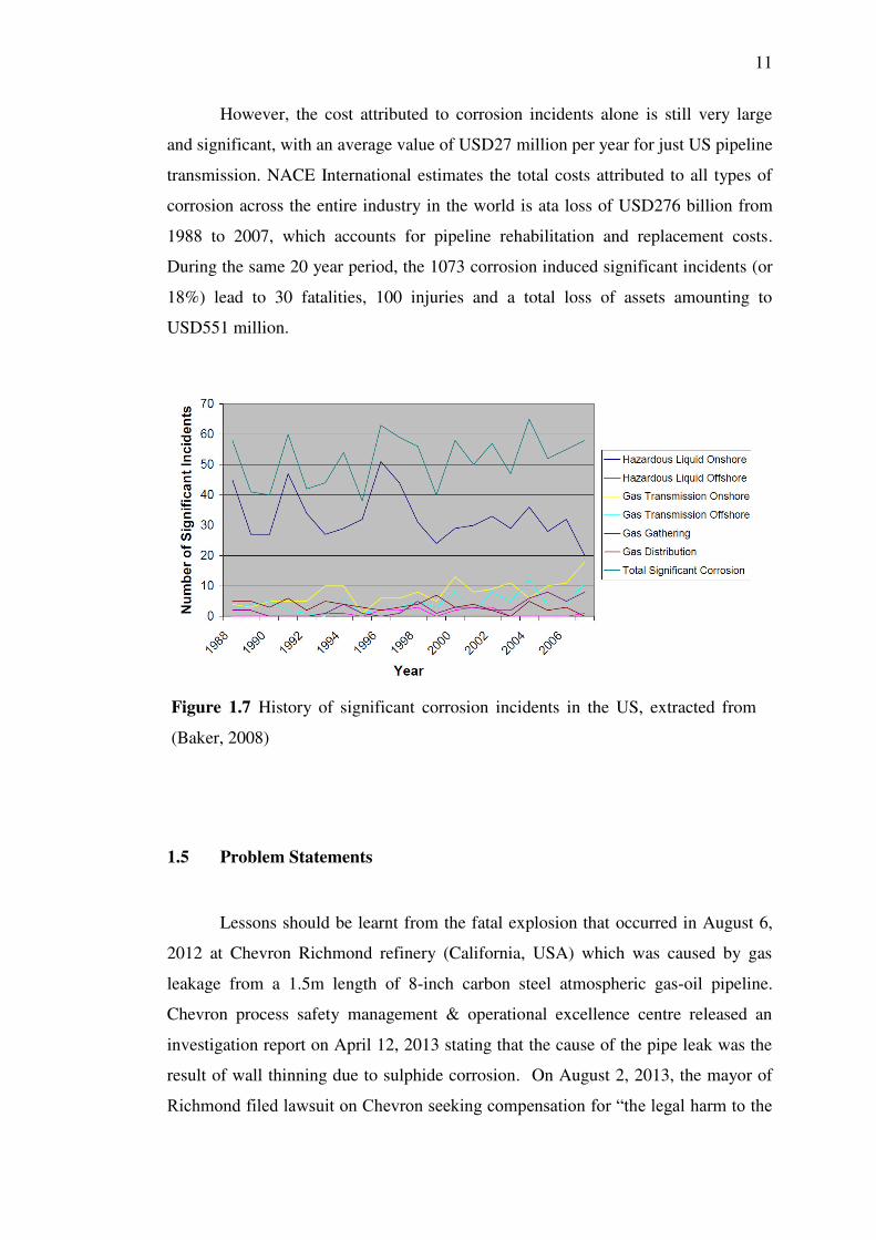
1.7 History of significant corrosion incidents in the US,
extracted from (Baker, 2008) 11
1.8 Explosion and fire caused by leakage in a 1.5m 8-inch
carbon steel pipe suffering from sulphide corrosion – HTM
PSM Case Reference 12
1.9 Evidence of sulfidation corrosion in the ruptured pipe 12
1.10 Typical sulphuric pipeline installed at HTM a) over ground
pipeline b) inside containment (or buried pipe) 12
2.1 Key milestones in the development of GWUT technology 19
2.2 Schematic of a general pit defect. The transition from the
localised to uniform corrosion morphology is defined by the
ratio of the pit diameter (D) and pit depth (T) (Galbraith &
Williamson, Practical considerations for users of guided
wave ultrasonic testing, 2008) 21

xvi
2.3 Schematic of common forms of corrosions (Davies J. ,
2000) 22
2.4 Group velocity dispersion curves for 6-inch schedule 40
steel pipe. (Demma A. C., The reflection of the fundamental
torsional mode from cracks and notches in pipes , 2003b) 23
2.5 Measured and predicted reflection coefficients for a
through-thickness notch in a 3 inch, schedule 40 steel pipe
at 70 kHz as a function of the circumferential extent of the
notch. L (0,2) mode input (Lowe M. , 1998) 26
2.6 The validation of the depth estimation method for the six
corrosion patches. Different markers represent the results
from the same defect shape reproduced in 4” (triangles) and
10” (circles) pipes. (Caradente & Cawley, 2011) 27
2.7 Six real corrosion patches scaled from the original 10” pipe
to a 4” pipe, represented in 3-D (Caradente & Cawley,
2011) 28
2.8 Finite element prediction of torsional mode reflection
coefficient from axially symmetric crack in 6 inch schedule
40 steel pipe as a function of crack depth. Also shown are
results for 24 inch pipe at 10 kHz and 50 kHz. (Demma A.
C., The reflection of the fundamental torsional mode from
cracks and notches in pipes , 2003b) 31
2.9 An example of a solid EFC ring for the use in small
diameter pipes (Guided-Ultrasonics Ltd, 2014) 33
2.10 Lightweight and portable equipment (Toughbook and
inflatable ring) makes pipe testing at site simpler. (Guided-
Ultrasonics Ltd, 2014) 33
2.11 Typical signals from (a) axisymmetric feature e.g. weld; (b)
corrosion (Lowe & Cawley, 2006) 35
2.12 Typical Guided Ultrasonics system report format (Guided
Ultrasonics Ltd, 2007) 35
2.13 Inspection of 10” pipe passing through earth wall from side
remote from defect (Lowe & Cawley, 2006) 38

xvii
2.14 Inspection of 10 inch pipe passing through earth wall from
other side of wall (Lowe & Cawley, 2006) 38
2.15 Test result on 3-inch pipe with bends at –F2, +F2 and +F3,
also showing corrosion at supports (-F1, +F1). The
reflection from the second bend weld at both –F2 and +F2
has a significant asymmetric (red) component, while the
reflection from the first weld is predominantly symmetric
(black). The bend +F3 occurs after the bend +F2 and this
shows significant asymmetric reflections from both welds.
This is due to mode conversion of the forward going wave
at bend +F2. (Lowe & Cawley, 2006) 40
2.16 Example of corrosion at simple supports. Clear indications
at S12 and S15; no significant corrosion at S11, S13, S14.
The double signal at S10 relates to a bend. F2 and F5 are
welds (Lowe & Cawley, 2006) 41
2.17 Dispersion curves for a 6-inch schedule 40 steel pipe,
showing only the order 0 and order 1 modes. (a) Phase
velocity for free pipe; (b) Phase velocity for pipe embedded
in concrete; (c) attenuation for pipe embedded in concrete
(Lowe & Cawley, 2006) 46
2.18 Dispersion curves for a steel bar embedded in concrete,
showing only the order 0 modes. (a) Energy velocity; (b)
Attenuation. After (Pavlakovic B. L., 2001) 47
2.19 Spectrum of reflection coefficient for L(0,1) mode in
cylindrical steel bar at location where bar enters polymer
adhesive. After (Vogt T. L., 2003) 48
2.20 Comparison between dispersion curves for a straight pipe
and those for a curved pipe. (a) Fundamental extensional
and flexural modes for a 2 inch diameter (5.5mm wall
thickness) steel pipe; (b) The equivalent modes in the same
pipe when bent to a curvature radius of 0.45m (Demma A.
C., The effect of bends on the propagation of guided waves
in pipes, 2005) 51

xviii
2.21 Predicted transmission coefficients for extensional mode
(L(0,2)) passing through bend of 3 inch pipe (wall thickness
5.5mm). (a) Coefficients versus frequency for different
bend radii; (b) Coefficients versus frequency for different
bend lengths (Demma A. C., The effect of bends on the
propagation of guided waves in pipes, 2005) 52
2.22 Reflection coefficient predictions and measurements for the
fundamental extensional mode L(0,2) at 70 kHz incident at
a circumferential notch in a pipe; (a) a part-depth notch
extending around 11% of the circumference; (b) a through-
thickness notch extending around part of the circumference,
also showing scattering conversion to other modes (Alleyne
D. L., 1998); (Lowe M. , 1998) 54
2.23 Key Elements of Pipeline Integrity (Hopkins, Pipeline
integrity-training our engineers and what they need to
know, 2001a) 60
3.1 Representation of the internal reflecting waves in an
isotropic plate 69
3.2 Phase velocity dispersion curves for the SH modes in a steel
plate (cs=3260 ms-1) generated from Disperse program,
where solid lines represent symmetric modes whilst dotted
lines represent anti-symmetric modes (Pavlakovic B. L.,
1997) 72
3.3 A schematic of the reflection of waves at the boundary
which is governed by Snell‟s law 73
3.4 The group velocity, cg, dispersion curves for the SH modes
in a steel plate (cs=3260 ms-1), where solid lines represent
symmetric modes whilst dotted lines represent anti-
symmetric modes 74
3.5 A schematic representation of the geometry of a hollow
cylinder or pipe and cylindrical coordinate set (r,θ,z) 75
3.6 Phase velocity dispersion curves for 3” steel schedule 40
pipe in a vacuum, where solid lines represent symmetric

xix
modes whilst dotted lines represent anti-symmetric mode
(Caradente & Cawley, 2011) 79
3.7 A comparison between longitudinal L(0,1) and L(0,2) phase
velocity dispersion curves in 3” and 8” schedule 40 pipes.
A0 and S0 Lamb modes are also displayed (Caradente &
Cawley, 2011) 81
3.8 A schematic representation of a) a pipe with cylindrical
coordinates and b) pipe (a) unrolled 81
3.9 A schematic of the geometries used during finite element
modelling of the scattering field from a through-thickness
circular hole with diameter of 28mm in a) a plate and b) 3”
schedule 40 pipe 83
3.10 a) Reflection coefficient (RC) spectrum from a circular
defect in a plate and in a 3” schedule 40 pipe b) Comparison
of the RC between the results from FE modelling and
Veilichko formula (Caradente & Cawley, 2011) 84
3.11 A group velocity dispersion curves for a 3” schedule 40
steel pipe (Caradente & Cawley, 2011) 85
4.1 Research methodology flow chart 91
4.2 The Wavemaker G4-mini 95
4.3 4” EFC Solid Ring 95
4.4 Direct transmission frequency transmission by transducer;
29.1138kHz; Amp = 18.249 FRF 97
4.5 4-inch deployable transducer ring showing top and bottom
halves and classification of segments. Model #: R2F04H;
Serial #: 3071; T14; Frequency range: 30-90 kHz; 2 rings 8
segments 98
4.6 Configuration of 40 physical transducers divided into 8
segments and 16 signal channels; (a) Transducer ring
diagnostic check, (b) diagram showing segment and
transducer numbering system for top half (A), (c) diagram
showing segment and transducer numbering system for
bottom half (B) 99

xx
4.7 Total 40 physical transducers consolidated to 16 segments
with 16 channels for Pulse-Echo Time Trace Display; data
#: 1062 for straight pipe without hole 100
4.8 Preparing test point location; (a) Laboratory straight pipe
set up, (b) 1mm hole drilled at 1.85m from transducer, (c)
the file number for the baseline signal recorded on the pipe
and (d) Data collection system set up using Wavemaker
Pipe Screening System (WPSS) manufactured by Guided
Ultrasonics Ltd. Model: G4m-410 with 4-inch transducer
ring (serial no.:R2F04H[3071]) 101
4.9 Environmental parameters monitored; (a) Mercury
thermometer for temperature measurement, (b) Machine
defect size 70mm x 70mm x 3mm left to corrode naturally 102
4.10 Axi-symmetric case; direction of hole in a straight pipe; (a)
upwards (N), (b) right (E), (c) downwards (S), and (d) left
(W) 105
4.11 Non axi-symmetric case; direction of bend; (a) bend
upwards (N), (b) bend right (E), (c) bend downwards (S),
and (d) bend left (W) 106
5.1 Examples of HTM‟s specific corrosion defects. a) pit
corrosion; b) patch corrosion 112
5.2 Laboratory straight pipe arrangement (axisymmetric case)
showing transducer, drilled hole (increasing diameter),
weld, clamped support and constant machined defect on a
4-inch NPS schedule 40 carbon steel pipe. Distance
between transducer and hole = 1.85m; distance between
transducer and weld = 3.44m; distance between transducer
and machined defect = 3.78m; distance from transducer to
far end of pipe = 4.18m; distance of transducer and near end
of pipe = 0.32m 115
5.3 Laboratory straight pipe set up 117
5.4 1mm hole drilled at 1.85m from transducer 117
5.5 Baseline signal data file record 117

xxi
5.6 Data collection system set up using Wavemaker Pipe
Screening System (WPSS) manufactured by Guided
Ultrasonics Ltd. Model: G4m-410 with 4.5-inch transducer
ring (serial no: R2F04H[3071]) 117
5.7 Mercury thermometer for temperature measurement 117
5.8 Machine defect size 70mm x 70mm x 3mm left to corrode
naturally 117
5.9 Drilled hole to represent localised corrosion and machined
slot to represent uniform corrosion 118
5.10 Laboratory pipe loop arrangement to monitor pit and patch
corrosion in pipe bends (non-axisymmetric case); pit
corrosion A1, is on inside radius of B1; patch corrosion is
on outside radius of B2 119
5.11 Schematic of laboratory pipe loop arrangement showing key
features 120
5.12 Huntsman Tioxide Malaysia 12-inch schedule 60 sulphuric
acid transportation pipeline from Port to Storage Tanks 121
5.13 Pipe supports plan for 12-inch schedule 60 sulphuric acid
pipeline near pig receiver (HTM construction drawing no.:
7665-00D20-012 by Simon Carves Ltd., U.K. in 1991) 123
5.14 Photo of 12-inch schedule 60 sulphuric acid pipeline near
pig receiver; demonstration of reliability and robustness of
guided wave testing instrument 124
5.15 Wavemaker G4 automatic diagnostic ring check for (a)
Segment balance, (b) Raw data time trace, and (c)
Capacitance balance. Transducer B3 at Segment 3 was
faulty 125
5.16 Transducer installed near datum weld JT134 in between
pipe supports referenced PS104 and PS105. The positive
direction of guided wave was set against sulphuric acid flow
and towards tunnel entry. The view of this photo show the
pipeline system leading towards the pig receiver 126
5.17 Transducer installed near datum weld JT134 in between
pipe supports referenced PS104 and PS105. The positive

xxii
direction of guided wave was set against sulphuric acid flow
and towards tunnel entry. The view of this photo show the
pipeline system leading towards the road tunnel entry 126
5.18 Pipe supports plan for 12-inch schedule 60 sulphuric acid
pipeline from tunnel entry to pig receiver 126
5.19 Placement of transducer at tunnel exit 127
5.20 Placement of transducer at straight pipe to screen entry and
exit pipe bends 127
5.21 Inspectable distance from; (a) TP2 with range 43m (b) TP3
with range 130m in each direction 127
5.22 Changes in signal trace caused by increasing defect size (i.e.
hole diameter) from a diameter of 2mm to 5mm in
increments of 1mm. At a diameter of 3mm, the signal trace
begin to show noticeable change although confidence level
of detection is low 130
5.23 Changes in signal trace caused by increasing defect size (i.e.
hole diameter) from a diameter of 6mm to 9mm in
increments of 1mm. At a diameter of 6mm, the signal trace
begin to show strong change as it touches the sensitivity
DAC line which was set to 1%. Confidence level of
detection is good. At 8mm diameter, the signal trace shows
very strong change with reading of CSC: 2%. Confidence
level of detection is now very good. Note that the
interaction of guided wave at A1 (6mm) has caused the
signal trace at A2 (machine defect) to change significantly 130
5.24 Changes in signal trace caused by increasing defect size (i.e.
hole diameter) from a diameter of 10mm to 13mm in
increments of 1mm. At a diameter of 13mm, the signal trace
showed strong change as it approaches the Call DAC line
which was set to 5%. Confidence level of detection is
extremely good. At 13mm diameter, the signal trace showed
a reading of CSC: 4%. Signal trace at A2 appear to remain
stable from 6 to 13mm diameter 131

xxiii
5.25 Growth monitoring of pitting corrosion; (a) in a symmetric
case i.e. straight pipe and (b) non-symmetric case i.e. bend 131
5.26 The results from the same position on the pipe at a
frequency regime (a) -0.4, (b) 0.0, (c) 4.0, and (d) 6.2 are
shown. The shape, size and amplitude of the defect change
dramatically 133
5.27 The results from the same position on the pipe at a
frequency regime (a) 6, (b) 0, (c) -6, and (d) -12 are shown.
The shape, size and amplitude of the defect change
dramatically. The C-scan provides a visual image of the
extent of the distortion of the signal trace 134
5.28 Enhanced Focusing Capability function used for the hole
and machined defect are shown in (a)-(c) and (e)-(f)
respectfully. Accurate measurements of the defects in the
axial direction was done using A-scan view and for the
circumference direction using C-scan view 136
5.29 Signal stability over 4 months of monitoring; (a) Month 1,
(b) Month 2, (c) Month 3, and (d) Month 4; Peak amplitude
(symmetric) at A1 remained stable at 4% CSC 138
5.30 Signal stability over 4 months of monitoring; baseline
signal recorded for weld stable to 1%, anomaly A2 at 2%
and anomaly A1 at 1% 139
5.31 Achievable inspection distance from test point 2 using
G4m-410#1047 and inflatable ring R2B12-2459, R2M:
35mm standard modules. The set test range was 130m with
16 averages and boosted voltage (~350 Vpp); Collecting
sequence using G4USB; Sequence sampling at 200kHz
(HP=10kHz, 16avg); Output voltage is 350V; Case
temperature is 37.5 OC; Analysis and data collection took
11.4 mins; Average signal to noise level is 55.6 dB 140
5.32 Signal trace collected from test point 2 (TP2). The end of
test is determined when the sensitivity and the call DACs
intersects (i.e. 5% CSC in this case); displayed in log scale.
Location: Pig receiver to tunnel entry at Huntsman Tioxide

xxiv
Malaysia. The maximum inspectable range in each direction
is approximately 110m 141
5.33 Maximum inspection range at straight sulphuric acid above
ground pipeline; approximately 110m in each direction;
displayed in linear scale. Location: Pig receiver to tunnel
entry at Huntsman Tioxide Malaysia 141
5.34 Maximum inspection range at straight sulphuric acid below
ground pipeline; approximately 43m in each direction;
displayed in log scale. Location: Pig receiver to tunnel entry
at Huntsman Tioxide Malaysia 142
5.35 Maximum inspection range at straight sulphuric acid below
road tunnel pipeline; approximately 43m in each direction;
displayed in linear scale. Location: Pig receiver to tunnel
entry at Huntsman Tioxide Malaysia 142
5.36 Inflatable ring transducer showing transducer no: 13
removed during inspection to demonstrate the durability of
instrument 143
5.37 Inflatable ring check before inspection 143
5.38 Signal trace with transducer no: 13 removed; the data file
shows good signal stability and interpretation of the result is
possible 144
5.39 An example of a baseline signal trace that can be used as a
reference for planning for maintenance activities in a
straight pipe system (symmetric case) 145
5.40 An example of a baseline signal trace that can be used as a
reference for planning for maintenance activities in a pipe
system with upward bend (non-symmetric case) 145
5.41 An example of a baseline signal trace that can be used as a
reference for planning for maintenance activities in a pipe
system with downward bend (non-symmetric case) 146
5.42 Inspection grid (a) schematic, and (b) superimposed unit
cell with circular defect. Overlap between the defect and the
transducer beam is represented by the grey area. (Evans &
Vogt, 2010) 154

xxv
5.43 Example calculation of P(x>0) as a function of defect
radius R for a square grid of 0.1 m length and a transducer
diameter of 10mm. It is equivalent to the maximum
achievable total POD (Evans & Vogt, 2010) 154
5.44 Field inspection grid length for a 12-inch sulphuric acid
pipeline 155
5.45 (a) various possible test positions at a distance of L from
each other on the pipe, and (b) unit grid cell schematic for
guided waves (Evans & Vogt, 2010) 156
5.46 GW inspection at confined space road crossing pipeline.
Culvert opening is less than 1m square 157
5.47 Schematic of road crossing pipeline indicating key features
in GW testing 158
5.48 Planned manual UT inspection points at J 150a, 150b, 150c
and 150d 159
5.49 GW test result for 12-inch sulphuric acid road crossing
pipeline running inside culvert which is below ground. A
typical example of an inaccessible situation for manual UT 160
5.50 (a) New 12-inch Schedule 60 pipe, (b) CSC=2.5%; defect
diameter (DD)=38mm; remaining wall thickness
(RWT)=4.6mm, (c) CSC=2.5%; DD=50mm; RWT=7.1mm,
(d) CSC=2.5%; DD=100mm; RWT=10.7mm 161
5.51 (a) Old 12-inch pipe with average wall thickness of
12.8mm, (b) CSC=2.5%; DD=38mm; RWT=4.1mm, (c)
CSC=2.5%; DD=50mm; RWT=6.2mm, (d) CSC=2.5%;
DD=100mm; RWT=9.6mm 162
6.1 12-inch sulfuric acid pipeline layout (shown in red) from
Kemaman Port to Storage tanks at Huntsman-Tioxide Plant 168
6.2 Graph of NPV against time for three different methods to
inspect the 2.745 km acid pipeline 171
7.1 Proposed manual UT inspection for a defect location
identified by GW test result. (a) Defect area identified by
GW test of 260 x 200mm, (b) Manual UT grid size of 65 x
50mm 175

xxvi
7.2 Proposed new pipeline inspection process flow diagram 175
7.3 Reported defect location. (a) Defect detected between PS
119 and PS 123, (b) axial distance from ring and
circumferential orientation of defect found 177
7.4 Defect characterisation. (a) B-Scan for detailed 3D
dimension report, (b) defect photograph evidence, (c) rough
estimate of defect size, and (d) manual UT thickness
measurement 178
7.5 Pressure wave propagation causing surge pressure 180
7.6 Calculations of the amplitude of wave pressure using
Equation 57 at (a) 2.5 ft/s, (b) 3.0 ft/s, and (c) 5.5 ft/s 181
7.7 Finite element analysis; (a) Model, (b) Wall hoop stress
versus Code design criteria analysis as adapted from
(Vicente & Risso, 2008) 183
7.8 Metal loss screening criteria; (a) longitudinal, (b)
circumferential 186

xxvii
LIST OF ABBREVIATIONS
CSC - Cross-sectional Change
DAC - Distance Amplitude Curve
EFC - Enhanced Focusing Capability
EHS - Environmental, Health & Safety
FR - Frequency Regime
GUL - Guided Ultrasonic Limited
HTM - Huntsman-Tioxide Malaysia
IGSB - Inter-Granite Sdn. Bhd.
LRUCM - Long Range Ultrasonic Condition Monitoring of Engineering
Assets
LRUT - Long Range Ultrasonic Testing
NDT - Non-destructive testing
PDE - Partial Differential Equation
PSM - Process Safety Management
PHMSA - Pipeline and Hazardous Materials Safety Administration
POD - Probability of Detection
RBI - Risk Based Inspection
SMEs - Small and Medium Sized Enterprises
TP - Test position
UT - Ultrasonic Thickness
WE - White End
WPPS - Wavemaker Pipe Screening System
WSE - Written Scheme of Examination

xxviii
LIST OF APPENDICES
APPENDIX TITLE PAGE
A Operator Temporary Level 1 Certificate 206
B Details of Supports and other features in Pipe Test
Rig (IGSB) 207
C Photograph of inspection test site at Huntsman-Tioxide
Malaysia 209
D Ultrasonic thickness survey reports for the inspected test
site at HTM 210
E 12” Pipe Layout Plan (Port to Tank) 213
F Laboratory Setup 2 (Picture & Isometric Drawing) 216
G Weld and Call DAC settings 217
H Pipeline Defect Assessment -- A Review &
Comparison of Commonly Used Methods 224

1
CHAPTER 1
INTRODUCTION
1.1 Structural Health Monitoring of Pipeline
Structural health monitoring (SHM) refers to the process of in-line
permanently installed monitoring sensors for effective management of structural
systems with respect to the potential occurrence of damage. The goal of a SHM
system is to decrease the cost of sustaining safe operations by facilitating condition-
based maintenance. In other words, the principal objective is to direct decision-
making based on the current health of the structure (Farrar & Worden, 2007). Whilst
related, SHM systems are distinguished in concept from non-destructive (NDE)
approaches in two major respects namely;
1. SHM systems utilise embedded sensors to provide monitoring without the
need to take the system offline for inspection.
2. SHM systems are focussed on more autonomous operation, reducing or
even eliminating the need for expert interpretation of results.
1.2 Guided Wave Ultrasonic Testing
Guided Wave Ultrasonic Testing (GWUT) or Long Range Ultrasonic Testing
(LRUT) is one of latest methods in the field of non-destructive evaluation. The
method employs mechanical stress waves that propagate along an elongated structure
while guided by its boundaries. This allows the waves to travel a long distance with

2
little loss in energy. Higher frequencies can be used in some cases, but detection
range is significantly reduced. In addition, the underlying physics of guided waves is
more complex than bulk waves. Much of the theoretical background has been
addressed in a Section 3.
Ultrasonic testing (UT) is a family of non-destructive testing techniques
based on the propagation of ultrasonic waves in the object or material tested. In most
common UT applications, very short ultrasonic pulse-waves with centre frequencies
ranging from 0.1-15 MHz, and occasionally up to 50 MHz, are transmitted into
materials to detect internal flaws or to characterize materials. A common example is
ultrasonic thickness measurement, which tests the thickness of the test object, for
example, to monitor pipework corrosion. The “Time of Flight” of an ultrasonic wave
is directly proportional to the thickness of the material measured. This is described
in Figure 1.1.
Figure 1.1 Principles of conventional UT

3
Figure 1.2 Comparison between conventional ultrasonic testing (UT) and guided
wave ultrasonic testing (GWUT)
While conventional UT measures the wall thickness at a spot, advanced
guided wave ultrasonic testing (GWUT) can identify locations of metal loss along a
length of the pipe (Guided Ultrasonics, 2010).
Some of the differences between conventional ultrasonic waves and guided
waves (see Figure 1.2) are;
1. Guided waves are mechanical stress waves that travel along the wall of the pipe;
therefore the entire volume of the pipe is inspected,
2. Frequencies used in guided wave inspection are much lower than conventional
ultrasonic testing; therefore the wave lengths are much longer and are scattered
instead of reflected from changes in the dimension of the wave guide; typically
between 30 – 75 KHz,
3. The pipe acts as a wave guide, permitting the waves to travel long distances,
4. The waves can be introduced at a single location into the pipe by one of two
systems and these are;
a) An array of piezoelectric crystals are positioned in modules that typically hold
two transducers each. The modules are spaced around the pipe under an air
bladder which when pressurized forces the units against the surface. The
individual crystals oscillate at the frequency at which they are excited and

4
transmit the wave into the pipe.
b) Coils of insulated wire are wrapped around the pipe. An alternating current is
passed through the coils, and an oscillating magnetic field is produced. Due to
the magnetostrictive effect of ferromagnetic materials, this produces a wave in
the pipe which can be amplified by using a nickel or cobalt strip bonded to the
pipe under the coil.
(a)
(b)
Figure 1.3 (a) Piezo electric crystals transducers (b) Magnetostrictive transducers
1.3 Background Problem and Motivation
Corrosion and erosion in pipes are a major concern within the chemical
industry specifically during the transportation of corrosive chemicals in steel pipes,
as it could lead to potential explosions or unscheduled plant down time. Both
economical and safety incentives drive the chemical industry to assess the health of
pipes which could lead to either down time or disasters.
For example, oil production from Alaska's Prudhoe Bay field was reduced by
95% (of its daily production of 630,000 barrels of oil) after a leak was discovered in
the Trans-Alaska Pipeline resulted in an increased in crude oil prices by over 2% (to
nearly USD90). British Petroleum (BP) suffered major losses which saw their share
value dipping by 2.5% at the FTSE 100 stock exchange in London (The Guardian,
2011).

5
In another example, the death toll from two huge blasts caused by leaked oil
from a ruptured pipeline in an eastern Chinese port city (Qingdao, China) had taken
62 lives with 150 injured and contaminated approximately 3,000 square feet of the
city. The pipeline owned by China's largest oil refiner, Sinopec, ruptured and leaked
for about 15 minutes onto a street and into the sea before it was shut off. Hours later,
as workers cleaned up the spill, the oil caught fire and exploded in two locations.
This incident was classified as one of the country's worst industrial accidents of the
year.
(a) Trans-Alaskan oil pipeline leak
(The Guardian, 2011)
(b) Qingdao city oil pipeline leak
(The Telegraph, 2013)
Figure 1.4 Examples of oil pipeline leakage accidents which had caused the loss
of human lives, environmental contamination and major financial loss

6
Figure 1.5 Sulphuric acid pipeline structural failure near Tiger Bay, Teluk
Kalong, at Huntsman Tioxide Malaysia
A further example of a major pipeline failure occurred locally at Huntsman
Tioxide Malaysia (HTM) located at Teluk Kalong, Terengganu. The pipeline
transports concentrated sulphuric acid to the plant and a major accident occurred
when a leak and pipe structural failure occurred at a stretch of the pipeline location as
shown in Figure 1.5. Although no injuries or fatalities were recorded but the incident
had tarnished the good reputation held by HTM over the past 20 years. A suitable
sulphuric acid pipeline integrity management system (PIMS) which complies with
industry standards is required to be implemented and this is the motivation of this
work.
As a result, the gas, refinery, chemical and petro-chemical industries seek to
detect damage to their pipeline systems at the earliest possible time. In order to do
this, it would require a form of structural health monitoring (SHM) system to be
implemented. Guided wave ultrasonic testing (GWUT) or long range ultrasonic
testing (LRUT) which is a new technology recently developed showed great potential
to address these issues and has been identified to be a possible inspection tool to
perform structural health monitoring (SHM) of pipelines carrying hazardous fluids.

7
Corrosion had been identified as one of the major factors which had caused
the pipelines to leak and in this work, the application of guided ultrasonic wave for
SHM of pipeline will be demonstrated in detail in both laboratory and field work.
The complexity of the corrosion profiles encountered in practice makes more
challenging the sizing of these discontinuities with guided ultrasonic waves. In the
literature many scientists and engineers have recognised similarities in the forms the
corrosion manifested in practice. These types of discontinuities can be classified in
specific groups by similarity of the mechanism of attack (Scoot, 1994) or appearance
of the corroded metal (Greene, 1967). Other authors have discussed the more typical
forms of corrosion related to specific metals and alloys (Uhlig, 1963) and (Evans U.
R., 1960). However, as with any classification system, the classification of these
corrosion types is not distinct or all-inclusive since more than one mode of attack
may occur.
Conventional methods for corrosion inspections and detection exist, typically
using ultrasonic and acoustics emission methods. There are however severe
limitations when the pipes or components to be tested are in extreme hazardous
environment, rendering such inspections feasible only during plant shutdowns. Such
inspections are done at discrete and localised locations which imply that such
assessment of the entire pipeline to a “hit or miss” affair, or extremely time
consuming if the inspections are extended along the entire pipe line. For example,
inspection of insulated pipework by spot removal poses problems such as break in
weather proofing and creating a potential entry point for future water ingress
(Horrocks, et al., 2010). Screening range using this method is also very little which
would give rise to the potential to miss sections with defect. Moreover,
inaccessibility of inspectors to carry out inspection also poses as a problem for
conventional UT methods for wall thickness inspection. Buried pipes under roads
and rail crossings will disable operators from inspection using conventional methods
unless expensive excavation work is carried out to expose the buried pipes. In
addition, there may not necessarily be enough space clearance to carry out these tests
such as radiography or UT in areas such as pipe racks or process pipes.

8
Devices known as maintenance pigs and smart pigs are currently being
implemented by being passed through a pipeline to measure wall thickness loss and
other structural anomalies. In addition, leak indicating pressure testing and
excavation to expose the surface of buried pipes for visual inspection are also used.
However, these techniques are invasive and not very effective if there are internal
obstructions, external dikes, or other complex geometric features along the pipeline.
Furthermore, these approaches do not provide sufficient information to predict the
future health of the piping unless a failure leading to leakage has already occurred. In
addition, these conventional techniques are time-based inspection methods which does
not offer a solution of monitoring the health of the structure at all times, which could
lead to missing of a serious defect between inspection periods.
Long range ultrasonic testing (LRUT) is an advanced non-destructive testing
(NDT) technology utilising guided ultrasonic wave. It is currently being
implemented to overcome the limitation of conventional methods by being able to
screen structures over a range of up to 100m from a single test location (Guided-
Ultrasonics Ltd, 2014). In addition, this technology can be implemented for pipeline
monitoring since the equipment can be retrofitted and permanently mounted onto
pipes to continuously monitor the health of pipes. This technology has been
developed and commercialised by a number of companies in the UK and US and it is
now included in the API 570 procedures as a new pipeline safety inspection tool.
Guided ultrasonic wave is a novel and promising technique which could offer a safe
and economically feasible solution for the industry to detect and monitor defects on
existing structures until the point is reached when they are deemed to be unsafe.
However, since this technology is new in Malaysia (and also other Asian countries),
the capability of the technology would therefore need to be demonstrated and
validated under field condition before local plant managers are convinced of possible
implementation in the industry.

9
1.4 Importance of the Study
Ageing of plant is commonly misunderstood as being how old an equipment
is. However, its correct association should be about plant equipment condition and
determining the extent of material deterioration and damage, which is usually but not
necessarily associated with time in service.
The typical ageing plant damage mechanism such as erosion and corrosion
then contributes to an increase in likelihood of equipment failure over the plant
lifetime. Studies from the EU Major Accident Database have shown that ageing has
a 50% contribution factor to technical integrity failure, which is the main factor
(60%) leading to major hazard loss of containment incident (Horrocks, et al., 2010).
See Table 1.1.
Corrosion and erosion induced pipe failures can either be pipe rupture or
leaks, with the latter being more common. As seen in Figure 1.6, excavation damage
and corrosion has been reported to be responsible for 1550 and 1073 significant
incidents respectively in both onshore and offshore US transmission pipelines, from
Table 1.1 : Average annual consequences of significant corrosion incidents between
1988 and 2007 (Horrocks, et al., 2010).

10
the period of 1988 through to 2008 (Baker, 2008). The US Department of
Transportation‟s Pipeline and Hazardous Materials Safety Administration (PHMSA)
defines an incident as significant if it causes fatality, an injury requiring
hospitalisation, cost of USD50K or more, release of 5 barrels or more of a highly
volatile liquid, 50 barrels or more of other liquids, or release of a liquid resulting in
an unintentional fire or explosion (Baker, 2008).
Figure 1.6 Causes of 5960 significant incidents in onshore and offshore pipelines
as adapted from (Baker, 2008)
On average there have been 52 significant incidents on US pipelines per year
caused by corrosion alone. These corrosion induced incidents involved onshore
hazardous liquid pipelines (63%), onshore gas transmission pipelines (15%), offshore
gas transmission pipelines, natural gas distribution lines, gas gathering lines and off
shore liquid lines (remaining %), as shown Figure 1.6. From Figure 1.7, the pattern
has been reported to be relatively consistent over time as a result of the industry‟s
effectiveness at corrosion control.
11
However, the cost attributed to corrosion incidents alone is still very large
and significant, with an average value of USD27 million per year for just US pipeline
transmission. NACE International estimates the total costs attributed to all types of
corrosion across the entire industry in the world is ata loss of USD276 billion from
1988 to 2007, which accounts for pipeline rehabilitation and replacement costs.
During the same 20 year period, the 1073 corrosion induced significant incidents (or
18%) lead to 30 fatalities, 100 injuries and a total loss of assets amounting to
USD551 million.
1.5 Problem Statements
Lessons should be learnt from the fatal explosion that occurred in August 6,
2012 at Chevron Richmond refinery (California, USA) which was caused by gas
leakage from a 1.5m length of 8-inch carbon steel atmospheric gas-oil pipeline.
Chevron process safety management & operational excellence centre released an
investigation report on April 12, 2013 stating that the cause of the pipe leak was the
result of wall thinning due to sulphide corrosion. On August 2, 2013, the mayor of
Richmond filed lawsuit on Chevron seeking compensation for “the legal harm to the
Figure 1.7 History of significant corrosion incidents in the US, extracted from
(Baker, 2008)

12
general public as well as to the assets and resources of the city of Richmond”, which
is still an on-going case at the time of writing of this thesis. See Figure 1.8 and
Figure 1.9. This case study was adopted by HTM as their “accident case reference”.
Huntsman process safety management group (PSM) had identified this
problem as “very severe” and had recommended that a condition based pipeline
monitoring system to be implemented in their Tioxide plant especially in all pipes
that carry sulphuric acid.
Figure 1.8 Explosion and fire caused by
leakage in a 1.5m 8-inch carbon steel pipe
suffering from sulphide corrosion – HTM
PSM Case Reference
Figure 1.9 Evidence of sulfidation
corrosion in the ruptured pipe
(a)
(b)
Figure 1.10 Typical sulphuric pipeline installed at HTM a) over ground
pipeline b) inside containment (or buried pipe)

13
Corrosion and erosion of sulphuric acid pipelines causing non-uniform wall
thinning are the major problems at Huntsman Tioxide Malaysia. This phenomenon
occurred more severely at pipe bends (see Figure 1.10a) than at the straight pipes
(see Figure 1.10b).
Current conventional sulphuric acid pipeline inspection program practiced by
HTM includes visual and UT thickness measurement inspection. Inspections are
done annually and the spot thickness checks are determined by qualified third party
independent NDT companies. In hazardous locations, inspections can only be
performed when the plant has been shut down and in “difficult to access” or non-
accessible locations inspections cannot be done.
1.6 Research Objectives
There are primarily two major objectives in this Doctorate of Engineering
programme and they are classified under (1) industrial and, (2) academic
requirements.
1.6.1 Industrial Objectives
In this research work, there are two main industrial objectives and they are;
(1) To quantitatively assess the technical capabilities of guided wave as an
inspection tool for the purpose of pipeline screening and structural health
monitoring of sulphuric acid pipelines.
(2) To economically assess and quantify the cost of inspection and monitoring
using guided waves.
The measurement of success in the achievement of the first objective was
discussed and agreed amongst Huntsman-Tioxide Malaysia (HTM) corporate process

14
safety management (PSM), Imperial College, London (ICL) and Universiti
Teknologi Malaysia (UTM). The agreed scope of work shall comply with API
570:1998 – Piping Inspection Code and are defined as follows;
(a) To assess the feasibility of detection of erosion and hydrogen induced defects
at bends and straight pipes,
(b) To establish the performance objectives of the guided wave pipe inspection
tool,
(c) To quantify the performance of the inspection tool under laboratory condition
and,
(d) To quantify the performance of the inspection tool under plant condition.
1.6.2 Academic Objective
Based on the definition of UTM‟s Engineering Doctorate (Engineering
Business Management) program published in 5-April 2013, “the research work must
demonstrate innovation in the application of knowledge to solve a significant
industrial problem. The work should make a significant contribution to the
performance of the company”.
1.7 Scope and Limitations of the Study
The intent of this work was to demonstrate practical and economically
feasible industrial applications of GWUT technology in SHM of pipelines. An
extensive literature review of the principles and applications of guided wave
technology was carried out, covering the period of 1991 to 2014.
The commercially available equipment used for the purpose of demonstration
was GUL‟s Wavemaker™ G4mini, which was introduced into the market in early
2014. Before demonstrating the technology at the field, a pipe test rig was fabricated

15
in the laboratory to verify the performance of this equipment at defect detection.
Using the deployable solid enhanced focusing capability (EFC) ring, baseline signals
were successfully established for the λm 4” pipe loop and two test locations (above
and below ground) on the 2.75km 12” sulphuric acid pipeline at Huntsman-Tioxide
pigment production plant.
Due to time restriction, implementation of the more suitable gPIMS™
permanently installed ring, which is designed to be permanently installed onto the
pipe (to give more stable readings for repeated monitoring) could not be carried out
for this pipe section. Based on the data collected from this site, a procedure specific
for these pipe sections was successfully devised for future implementation by
Huntsman-Tioxide.
A preliminary economic analysis for the plant wide implementation of guided
wave for the purpose of SHM was also investigated upon.
1.8 Structure of this Dissertation
This dissertation is divided into nine chapters. Chapter 1 introduces the effect
of problems associated with corrosion in which the chemical industry faces. These
problems includes billions of dollars‟ worth of cost every year, produces about 50
fatality globally each year and damages to the environment.
Chapter 2 provides an extensive literature review of the commercial available
ultrasonic guided waves products in the market. The history of the technological
development of these products is briefly covered here. The current usage capabilities
and limitations of these equipment and feasibility for screening pipes successfully are
discussed in great details in this chapter. In addition, this chapter covers the
proposed future technological improvements on ultrasonic guided wave equipment
which are currently undergoing research and development.

16
Chapter 3 provides the background theory to ultrasonic guided waves
propagating in structures. Shear horizontal (SH) waves in plates and torsional guided
waves in pipes are emphasised in this thesis due to relevance to thesis. The analogy
between the propagation of guided waves in pipes and plates is also presented. In
addition, the choice of mode, frequency range and a general procedure to conduct
finite element simulations are discussed in this chapter.
Chapter 4 outlines the methodology of this research work. It identifies the
industrial problem and reviews the current industrial best practice for pipeline
inspection systems. A thorough research of new NDT innovations available
commercially in the market is discussed and the selection of guided wave testing
(GWT) which is an advanced NDT technology is decided based upon its excellent
defect detection capability. Rigorous training of the GW technology by Guided
Ultrasonics Ltd. to familiarise with the technology acquired was done in order for the
instrument to be applied at both laboratory level and pilot study at the industrial
plant.
Chapter 5 describes the industrial case study which was done at Huntsman
Tioxide, Malaysia to demonstrate the capability of GWT as a pipe screening
instrument with 100% wall coverage. A list of GW performance targets including its
success criteria was set by Hunstman as the objectives for the case study. The
outcome of the case study was very favourable and demonstrated that GW
technology was successful in meeting all the performance targets set.
Chapter 6 proposes a new pipe inspection procedure which combines the
current conventional NDT with advanced NDT methods to offer an improved defect
detection system to Huntsman‟s pipe integrity management system. In this chapter,
the probability of detection (POD) of a defect in both NDT methods are discussed in
detail and the benefit of combining the two methods are described.
Chapter 7 assesses the cost implications in the implementation of this new
pipe inspection procedure in the plant‟s pipeline integrity management system. It not
only shows how the improved defect detection system can prevent accidents from

17
occurring but also saves unnecessary cost to plant operators since only the section of
pipes screened with defects need to be followed up with manual UT inspection. If
the pipeline has few defects, it could save plant operators more than 50% of the
existing pipe inspection cost.
Chapter 8 details out the proposed general preliminary structural health
monitoring procedure for the transportation pipes involved in HTM‟s process flow.
Chapter 9 summarises the key findings and contribution of this work along
with recommendation for future works.

194
REFERENCES
A. Demma, D. A. (2011). Inspection of Pipes using Guided Waves : state of the art.
5th Pan American Conference for NDT. Mexico.
Abaqus. (2010). User Manual Version 6.9. Retrieved from www.simulia.com
Alleyne, D. a. (1992a). Optimisation of Lamb wave inspection techniques. NDT&E
International, Vol 25, pp11-22.
Alleyne, D. a. (1992b). The interaction of Lamb waves with defects. IEEE Trans
UFFC, Vol 39, pp381-397.
Alleyne, D. a. (1996a). The excitation of Lamb waves in pipes using dry coupled
piezoelectric transducers. J NDE, Vol 15, pp11-20.
Alleyne, D. a. (1997). Long range propagation of Lamb waves in chemical plant
pipework. Materials Evaluation, Vol 55, pp504-508.
Alleyne, D. C. (1997). The Lamb Wave Inspection of Chemical Plant Pipework.
Review of Progress in Quantitative NDE, Vol 16, DO Thompson and DE
Chimenti (eds), Plenum Press, New York, pp1269-1276.
Alleyne, D. L. (1998). The reflection of guided waves from circumferential notches
in pipes. ASME J Applied Mechanics, Vol 65, pp635-641.
Alleyne, D. N., & Cawley, P. (1992). The interaction of lamb waves with defects.
IEEE Transactions on Ultrasonics, Ferroelectrics, and Frequency control,
39(3):381.
Alleyne, D. P. (2001). Rapid, long range inspection of chemical plant pipework using
guided waves. Insight, Vol 43, pp93-96.
Alleyne, D., & Cawley, P. (1991). A two-dimensional fourier transform method for
the measurement of propagating multimode signals. Journal of Acoustical
Society of America, 89(3), 1168.
Alleyne, D., & Cawley, P. (1996a). The excitation of Lamb waves in pipes using dry
coupled piezoelectric transducers. J NDE, Vol 15, pp11-20.

195
Alleyne, D., & Cawley, P. T. (1996b). The effect of discontinuities on the long range
propagation of Lamb waves in pipes. Proc I Mech E, Part E: J Process mech
Eng, Vol 210, pp217-226.
Anon. (1999). Guide on methods for assessing the acceptability of flaws in fusion
welded structures. BS 7910 : 1999, Incorporating Amendment No. 1, British
Standards Institution, London, UK.
Anon. (2001). Managing System Integrity for Hazardous Liquid Pipelines. API
Standard 1160 (ANSI/API STD 1160-2001), First Edition, November.
API 570. (1998). Piping Inspection Code. American Petroleum Institute, 2nd edition.
API 579-1, A. P. (2007). API 579-1: Fitness for service.
API 579-1/ASME FFS-1. (2007). Fitness-for-service .
ASME B31.4. (1999). Pipeline transportation systems for liquid and hydrocarbonss
and other liquids. (1998 ed.). New York.
ASTM-E2775-11. (2011). Standard Practice for Guided Wave Testing of Above
Ground Steel Pipework Using Piezoelectric Effect Transduction. ASTM.
ASTM-E2929-13. (2013). Standard Practice for Guided Wave Testing of Above
Ground Steel Piping with Magnetostrictive Transduction. ASTM.
Auld, B. (1990). Acoustic fields and waves in solids. Kreiger, Malabar, Florida.
Bai, H. S. (2001). Scattering of guided waves by circumferential cracks in steel
pipes. ASME J Applied Mechanics, Vol 68, pp619-631.
Baker, M. (2008). Pipeline Corrosion. U.S. Department of Transportation Pipeline
and Hazardous Material Safety Administration Office of Pipeline Safety.
Beard, M. L. (2002). Development of a guided wave inspection technique for rock
bolts. Insight, Vol 44, pp19-24.
Beard, M. L. (2003a). Ultrasonic guided waves for inspection of grouted tendons and
bolts. ASCE J Materials in Civil Engineering, Vol 15, pp212-218.
Beard, M. L. (2003b). Non-destructive testing of rock bolts using guided ultrasonic
waves. Int J Rock Mech & Mining Sci, Vol 40, pp527-536.
Beaumont, M. R. (2006). Mechanical Integrity Best Practice for Sulphuric Acid
Plants. Loss prevention symposium.
Böttger, W. S. (1987). Prototype EMAT system for tube inspection with guided
ultrasonic waves. Nuclear Eng. and Design, Vol 102, pp356-376.
Brotton, J. (2002). Corrosion at pipe supports: Causes and solutions. Technical
report, Deepwater Corrosion Services.

196
BS9690. (2011). Non-destructive testing – Guided wave testing – Part 1: General
principles. BSI.
BS9690. (2011). Non-destructive testing – Guided wave testing – Part 2: Basic
requirements for guided wave testing of pipes, pipelines and structural
tubulars. BSI.
BS9690. (2011). Non-destructive testing – Guided wave testing – Part 2: Basic
requirements for guided wave testing of pipes, pipelines and structural
tubulars. BSI.
Caradente, R., & Cawley, P. (2011). Interaction between the fundamental torsional
guided wave mode and complex defects in pipe. London: Imperial College
London.
Carandente, R. (2012). Interaction between the fundamental torsional guided wave
mode and complex defects in pipes. Imperial College PhD thesis.
Castaings, M. L. (2002). Modal decomposition method for modelling the interaction
of Lamb waves with cracks. J Acoust Soc Am, Vol 112, pp2567-2582.
Cawley, P. A. (1994). Inspection of pipes. WO 96/12951, priority date 20-10-1994.
Cawley, P. L. (2003). Practical long range guided wave inspection - applications to
pipes and rail. Materials Evaluation, Vol 61, pp66-74.
Cawley, P., Cegla, F., & Stone, M. (2012). Corrosion monitoring strategies-Choice
between area and point measurements. J NonDestructive Evaluation(DOI
10.1007/s10921-012-0168-2).
Cho, Y. a. (1996). A boundary element solution for a mode conversion study on the
edge reflection of Lamb waves. J Acoust Soc Am, Vol 99, pp2097-2109.
Cho, Y. H. (1997). Lamb wave scattering analysis for reflector characterization.
IEEE Trans UFFC, Vol 44, pp44-52.
Clarke, T. (2009). Guided Wave Health Monitoring Of Complex Structures.
Clarke, T., Simonetti, F., & Cawley, P. (2010). Guided wave health monitoring of
complex structures by sparse array systems: influence of temperature changes
on performance. Journal of Sound and Vibration.
Cosham, A., & Hopkins, P. (2004). The assessment of corrosion in pipelines –
guidance in the pipeline. Amsterdam.
Cosham, A., & Hopkins, P. (2004). The assessment of corrosion in pipelines –
guidance in the pipeline defect assessment manual (PDAM). Amsterdam, The

197
Netherlands: Pipeline Pigging and Integrity Management Conference 17-18th
May.
Daryl Corbin, E. W. (2007). New Technology for Real-Time Corrosion Monitoring.
TRI-SERVICE Corrosion Conference.
Datta, S. S. (1982). Diffraction of medium and long wavelength horizontally
polarized shear waves by edge cracks. J Appl Phys, Vol 53, pp2895-2903.
Daud, M. A. (2011). Report of Examination of Piping. Axiom Engineering
Associates Ltd.
Daud, M. A. (2011). Report of Examination of Piping. Axiom Engineering
Associates Ltd.
Davies, J. (2000). Corrosion: Understanding the basics. ASM International.
Davies, J. O. (2008). Inspection of Pipes using Low Frequency Focused Guided
Wave. London: Imperial College London.
Davies, J. R. (2000). Corrosion: Understanding the basics. ASM International.
Davies, J. S. (2006). Review of Synthetically Focused Guided Wave Imaging
Techniques with Application to Defect Sizing. Review of Progress in
Quantitative NDE, Vol 25, DO Thompson and DE Chimenti (eds), American
Institute of Physics, in press.
Demma, A. A. (2003c). Testing offshore risers using guided waves. internal report,
Guided Ultrasonics Ltd..
Demma, A. C. (2003a). Scattering of the fundamental shear horizontal mode from
steps and notches in plates. J Acoust Soc Am, Vol 113, pp1880-1891.
Demma, A. C. (2003b). The reflection of the fundamental torsional mode from
cracks and notches in pipes . J Acoust Soc Am, Vol 114, pp611-625.
Demma, A. C. (2004). The reflection of guided waves from notches in pipes: a guide
for interpreting corrosion measurements. NDT&E International, Vol 37,
pp167-180.
Demma, A. C. (2004). The reflection of guided waves from notches in pipes: a guide
for interpreting corrosion measurements. NDT&E International, Vol 37,
pp167-180.
Demma, A. C. (2005). The effect of bends on the propagation of guided waves in
pipes. Trans ASME J Pressure Vessel Technology, Vol 127, pp328-335.
Demma, A. C. (2005). The effect of bends on the propagation of guided waves in
pipes. Trans ASME J Pressure Vessel Technology, Vol 127, pp328-335.

198
Diligent, O. a. (2005). Reflection of the S0 Lamb mode from a flat bottom circular
hole. J Acoust Soc Am, Vol 118, pp2869-2879.
Diligent, O. G. (2002). The low frequency reflection and scattering of the S0 Lamb
mode from a circular through-thickness hole in a plate: Finite Element,
analytical and experimental studies. J Acoust Soc Am, Vol 112, pp2589-2601.
Ditri, J. (1996). Some results on the scattering of guided elastic SH waves from
material and geometric waveguide discontinuities. J Acoust Soc Am, Vol 100,
pp3078-3087.
Doosan Babcock Energy Limited. (2009). Evaluation of the effectiveness of non-
destructive testing screening methods for in-service inspection. Health and
Safety Executive.
Edwards, G. (2006). Long Range Ultrasonic Testing – New Markets for New
Technology. Long Range Ultrasonic Condition Monitoring of Engineering
Assets (Coll-CT-2005-516405).
Edwards, G. (2006). New Markets for New Technology - Long Range Ultrasonics
Testing. LRUCM Consortium. TWI Ltd.
Engelhardt, G., & Macdonald, D. (1998). Deterministic prediction of pit depth
distribution. Journal of Corrosion NACA, 469-479.
Evans, M., & Vogt, T. (2010). Reliability of guided wave testing. ENDT.
Evans, M., & Vogt, T. (2010). Reliability of guided wave ultrasonic testing. ECNDT
- Moscow.
Evans, U. R. (1960). The corrosion and oxidation of metals. Edward Arnold Ltd.
Farrar, C., & Worden, K. (2007). An introduction to structural health monitoring.
Sheffield: Philosophical Transaction ofthe Royal Society.
Fitch, A. (1963). Observation of elastic-pulse propagation in axially symmetric and
non-axially symmetric longitudinal modes of hollow cylinders. Journal of the
Acoustical Society of America, 35(5), 706-708.
Fortunko, C. K. (1982). Nondestructive evaluation of planar defects in plates using
low frequency SH waves. J Appl Phys, Vol 53, pp3450-3458.
Fromme, P. W. (2005). A guided ultrasonic wave array for structural integrity
monitoring. Review of Progress in Quantitative NDE, Vol 24, DO Thompson
and DE Chimenti (eds), American Institute of Physics, pp1780-1787.
Galbraith, J. M., & Williamson, G. C. (2008). Practical considerations for users of
guided wave ultrasonic testing. NACE International, 07164.

199
Galbraith, J. M., & Williamson., G. C. (2008). Practical considerations for users of
guided wave ultrasonic testing. NACE International, 07164.
Galvagni, A. (2013). Pipeline Health Monitoring.
Galvagni, A. (2013). Pipeline Health Monitoring. Imperial College London PhD
Thesis.
Gazis, D. (1959). Three dimensional investigation of propagation of waves in hollow
circular cylinders. Journal of the Acoustical Society of America, 31(5), 568-
578.
Grahn, T. (2003). Lamb wave scattering from a circular partly through-thickness
hole in a plate. Wave Motion, Vol 37, pp63–80.
Greene, M. G. (1967). Corrosion Engineering. McGraw Hill.
Gridin, D. C. (2003). The high-frequency asymptotic analysis of guided waves in a
circular elastic annulus. Wave Motion, Vol 38, pp67-90.
Grills, R. H. (2001). Probability of Detection - A NDT Solution. Retrieved from
http://www.asnt.org/publications/materialseval/solution/jul01solution/.
Guided Ultrasonics Ltd. (2007). Wavemaker G3 Procedure based Training Manual.
Guided Ultrasonics, L. (2010). GUL 105: 2010 Standard Practice for the GWT of
Basic Pipe-work using the Wavemaker G3 Pipe Screening System (2 ed.).
Nottingham.
Guided-Ultrasonics Ltd. (2014). Retrieved from Guided-Ultrasonics Ltd:
http://www.guided-ultrasonics.com
GUL, G. U. (2013). gPIMS Sensors. Retrieved from http://www.guided-
ultrasonics.com/public2013/?page_id=922.
Haddara, F. I. (2003). Risk-based maintenance (rbm): a quantitative approach. J.
Loss Prevent. Proc.,.
Hardy, F. (2009). Evaluation of the effectiveness of non-destructive testing screening
methods for in-service inspection.
Hassan, W. a. (1997). Circumferential creeping waves around a fluid-filled
cylindrical cavity in an elastic medium. J Acoust Soc Am, Vol 101, pp2496-
2503.
Hayashi, T. a. (2002). Multiple reflections of Lamb waves at a delamination.
Ultrasonics, Vol 40, pp193-197.
Hayashi, T. a. (2005). Defect imaging with guided waves in a pipe. J Acoust Soc Am,
Vol 117, pp2134-2140.

200
Hayashi, T. K. (2003). Analysis of flexural mode focusing by a semianalytical finite
element method. J Acoust Soc Am, Vol 113, pp1241-1248.
Haynes, C. M. (2014). Effective Health Monitoring Strategies for Complex
Structures. University of Calfornia, San Diego.
Hopkins, P. (2001a). Pipeline integrity-training our engineers and what they need to
know. Mexico.
Hopkins, P. (2001b). Pipeline integrity reviews. Houston: Clarion Press.
Horrocks, P., Mansfield, D., Parker, K., Thompson, J., Atkinson, T., & Worsley, J.
(2010). Managing Ageing Plant. Health & Safety Executives (HSE) Books.
HSE. (2012). Failure rate and event data for use within risk assessments. Retrieved
October 7, 2014, from www.hse.gov.uk/landuseplanning/failure-rates.pdf
http://www.guided-ultrasonics.com. (2011, 07 09). Retrieved 07 09, 2011
Huntsman. (2010). Sustainability Report : We See A Better World.
Hutchins, D. J. (1993). Lamb Wave Tomography using noncontact transduction.
Ultrasonics, Vol 31, pp97-103.
Ideris, E., & Yahya, M. F. (2010). 12" Acid Sulphuric Pipeline-12-R17-031-II (01)-
Visual and UTTM Inspection Report. Malaysia: TestEx (M) Sdn Bhd.
K. Worden, C. R. (2007). The fundamental axioms of structural health monitoring.
Proc. R. Soc. A, vol. 463, p. 1639.
Kiefner, J. F., & Leewis, K. (2011). Pipeline Defect Assessment - A Review &
Comparison of Commonly Used Methods. Report No. L52314.
King, R. a. (1982). Extended variational solution for scattering from flaws in plates.
J Appl Phys, Vol 53, pp3459-3460.
Koshiba, M. H. (1987). Finite Element solution of horizontally polarized shear wave
scattering in an elastic plate. IEEE Trans UFFC, Vol 34, pp461-466.
Koshiba, M. K. (1984). Finite Element analysis of Lamb wave scattering in an elastic
plate waveguide. IEEE Trans Son Ultrason, Vol SU-31, pp18-25.
Kwun, H. a. (1995). Feasibility of under-lagging corrosion detection in steel pipe
using the magnetostrictive sensor technique. NDT&E International, Vol 28,
pp211-214.
Kwun, H. a. (1995). Feasibility of under-lagging corrosion detection in steel pipe
using the magnetostrictive sensor technique. NDT&E International, Vol 28,
pp211-214.

201
Kwun, H. K. (2003). The magnetostrictive sensor technology for long range guided
wave testing and monitoring of structures. Materials Evaluation, Vol 61,
pp80-84.
Le Clezio, E. C. (2002). The interaction of the S0 Lamb mode with vertical cracks in
an aluminium plate. Ultrasonics, Vol 40, pp187-192.
Lewis, K. (2001). Integrity Management of Pipelines. Congreso Internacional de
Ductos (International Pipeline Congress), Mérida, Yucatán, Mexico, 14-16
November.
Li, J. (2005). On circumferential disposition of pipe defects by long range ultrasonic
guided waves. Trans ASME J Pressure Vessel Technology, Vol 127, pp530-
537.
Li, J. a. (2002). Angular-profile tuning of guided waves in hollow cylinders using a
circumferential phased array. IEEE Trans UFFC, Vol 49, pp1720-1729.
Liu, G. a. (1998). Guided circumferential waves in a circular annulus. ASME J
Applied Mechanics, Vol 65, pp424-430.
Liu, Z. H. (2006). Circumferential and longitudinal defect detection using T(0,1)
mode excited by thickness shear piezoelectric elements. Ultrasonics, Vol 44
(in press) (Presented at UI/WCU conference Beijing, Sept 2005).
Lowe, M. (1998). Characteristics of the reflection of Lamb waves from defects in
plates and pipes. Review of Progress in Quantitative NDE, Vol 17, DO
Thompson and DE Chimenti (eds), Plenum Press, New York, pp113-120.
Lowe, M. A. (1998). The mode conversion of a guided wave by a part-
circumferential notch in a pipe. ASME J Applied Mechanics, Vol 65, pp649-
656.
Lowe, M. C.-Y. (2002b). The low frequency reflection characteristics of the
fundamental antisymmetric Lamb wave a0 from a rectangular notch in a
plate. J Acoust Soc Am, Vol 112, pp2612-2622.
Lowe, M. D. (2002a). Low frequency reflection characteristics of the S0 Lamb wave
from a rectangular notch in a plate. J Acoust Soc Am, Vol 111, pp64-74.
Lowe, M., & Cawley, P. (2006). Long Range Guided Wave Inspection Usage -
Current Commercial Capabilities and Research Directions. Department of
Mechnical Engineering, Imperial College London.
Luo, W. R. (2004). Circumferential shear horizontal wave axial crack sizing in pipes.
Research in Nondestructive Evaluation, Vol 15, pp149-171.

202
McKeon, J. a. (1999a). Lamb wave scattering from a through hole. J Sound Vib, Vol
224, pp843-862.
McKeon, J. a. (1999b). Parallel projection and crosshole Lamb wave contact
scanning tomography. J Acoust Soc Am, Vol 106, pp2568-2577.
Mirsky, I. (1965). Wave propagation in transversely isotropic circular cylinders, Part
1: Theory. Journal of the Acoustical Society of America, 37(6), 1016-1021.
Mohr, W. a. (1976). On inspection of thin walled tubes for transverse and
longitudinal flaws by guided ultrasonic waves. IEEE Trans Sonics and
Ultrasonics, Vol SU-23, pp369-374.
Moser, F., Jacobs, L., & Qu, J. (1999). Modelling elastic wave propgation in
waveguides with the finite element method. NDT & E international, 32, 225-
234.
Mudge, P. (2001). Field application of the Teletest long range ultrasonic testing
technique. Insight, Vol 43, pp74-77.
Mudge, P. a. (1997). Detection of corrosion in pipes and pipelines. ASNT
International Chemical and Petroleum Industry Inpection Technology
Topical Conference V, Houston Texas.
Nagy, P. B. (1994). Weep hole inspection by circumferential creeping waves. NDT &
E Int, Vol27, pp131-142.
Nishino, H., Takashima, S., Uchida, F., Takemoto, M., & Ono, K. (2001). Modal
analysis of hollow cylindrical guided waves and applications. Japanese
Journal of Applied Physics, 40, 364-370.
Norris, A. a. (1995). Scattering of flexural waves on this plates. J Sound Vib, Vol
181, pp115-125.
Norris, A. a. (1997). Flexural wave propagation and scattering on thin plates using
Mindlin theory. Wave Motion, Vol 26, pp1-12.
Ogilvy, J. A. (1993). NDT & E International, Vol 26, No 1.
Olympus. (2012). http://www.olympus-ims.com/en/pipewizard/. Retrieved August 23,
2015
Paris, P., & Erdogan, F. (n.d.). A critical analysis of crack propagation laws. Journal
of Basic Engineering (Trans. ASME) 85D (4) 528 to 534.
Patel, R. J. (2005). Risk Based Inspection. Middle east non-destructive testing
conference. Bahrain.

203
Pavlakovic, B. (1998). Leaky guided ultrasonic waves in NDT. London: Imperial
College London.
Pavlakovic, B. L. (1997). Disperse: a general purpose program for creating
dispersion curves. Review of Progress in Quantitative NDE, Vol 16, DO
Thompson and DE Chimenti (eds), Plenum Press, New York, pp185-192.
Pavlakovic, B. L. (2001). High frequency low loss ultrasonic modes in embedded
bars. ASME J Applied Mechanics, Vol 68, pp67-75.
PHMSA. (2007). Guided wave UT Target items for go-no go procedures - the ‘18
point’ guidelines. PHMSA.
PHMSA. (2010, March 1). Guidelines for integrity assessment of cased pipe for gas
transmission pipelines in high consequence areas (HCAs), Revision 0, publ.
Retrieved from http://primis.phmsa.gov/gasimp/documents.htm
RACH. (1999). Reliability Assessment for Containment of Harzardous Materials
(RACH). European Commission Project OG 112/FR/UK, Final Report.
Richardson, S. (2012). Safety & Loss Prevention (Lecture Notes) (pp. 1-12 ed.).
Imperial College London.
Rokhlin, S. (1980). Diffraction of Lamb waves by a finite crack in an elastic layer. J
Acoust Soc Am, Vol 67, pp1157-1165.
Rokhlin, S. (1981). Resonance phenomenon of Lamb waves scattering by a finite
crack in a solid layer. J Acoust Soc Am, Vol 69, pp922-928.
Rose, J. (1999). Ultrasonic waves in solid media.
Rose, J. D. (1999). A guided wave inspection technique for nuclear steam generator
tubing. Cambridge University Press.
Rose, J. L. (2004). Ultrasonic Waves in Solid Media. Pennsylvania: Cambridge
University Press.
Rose, J. L. (2005). A natural focusing low frequency guided wave experiment for the
detection of defects beyond elbows. ASME J Pressure Vessel Technology,
Vol 127, pp310-316.
Rose, J. S. (2003). Guided wave flexural mode tuning and focusing for pipe
inspection. Materials Evaluation, Vol 61, pp162-167.
Scoot, S. D. (1994). Corrosion in the petrochemical industry. ASM International.
Shin, H. a. (1998). Guided wave tuning principles for defect detection in tubing. J
NDE, Vol 17, pp27-36.

204
Sicard, R. C. (2004). Guided Lamb waves and L-SAFT processing techniques for
enhanced detection and imaging of corrosion defects in plates with small
depth-to-wavelength ratio. IEEE Trans UFFC, Vol 51, pp1287-1297.
Sicard, R. G. (2002). A SAFT algorithm for Lamb wave imaging of isotropic plate-
like structures. Ultrasonics, Vol 39, pp487-494.
Silk, M. G. (1979). The propagation in metal tubing of ultrasonic wave modes
equivalent to Lamb waves. Ultrasonics, Vol 17, pp11-19.
Silk, M. G., & Bainton, K. F. (1979). The propagation in metal tubing of ultrasonic
wave modes equivalent to Lamb waves. Ultrasonics, Vol 17, pp11-19.
Simonetti, F. a. (2004). On the nature of shear horizontal wave propagation in elastic
plates coated with viscoelastic materials. Proc Royal Soc Lond:
Mathematical, Physical and Engineering Sciences, Vol 460, pp2197-2221.
Simonetti, F. a. (2005). On the nature of shear horizontal wave propagation in elastic
plates coated with viscoelastic materials. Proc Royal Soc Lond:
Mathematical, Physical and Engineering Sciences, Vol 460, pp2197-2221.
Sun, Z. Z. (2005). Flexural torsional guided wave mechanics and focusing in pipe.
ASME J Pressure Vessel Technology, Vol 127, pp471-478.
The Guardian. (2011). http://www.theguardian.com/business/2011/jan/10/bp-shuts-
alaska-pipeline-after-leak. Retrieved August 21, 2015
The Telegraph. (2013).
http://www.telegraph.co.uk/news/worldnews/asia/china/10469661/Death-toll-
from-Chinese-pipeline-explosion-rises.html. Retrieved August 22, 2015
Thompson., N. G. (2006). Gas and liquid transmission pipelines. Technical report,
CC Technologies.
U45000990. (2008). Non-destructive testing - Inspection of above-ground steel
pipelines using guided waves. Italian Organisation for Standardisation (UNI).
Uhlig, H. H. (1963). Corrosion and corrosion control. John Wiley & Sons.
Valle, C. N. (2001). Crack characterization using guided circumferential waves. J
Acoust Soc Am, Vol 110, pp1282-1290.
Valle, C. Q. (1999). Guided circumferential waves in layered cylinders. Int. J. Eng.
Sci., Vol 37, pp1369-1387.
Velichko, A., & Wilcox, P. (2009). Excitation and scattering of guided waves:
relationshipos between soluition for free plates and pipes. Journal of the
Acoustical Society of America, 125(6), 3623-3631.

205
Vicente, F., & Risso, E. (2008). Argentine NGL case study applies economic
procedure. Neuquen: Oil & Gas Journal.
Vogt, T. L. (2003). The scattering of guided waves in partly embedded cylindrical
structures. J Acoust Soc Am, Vol 113, pp1258-1272.
Vogt, T., & Evans, M. (2009). 4th European-American Workshop on reliability of
NDE, We.4.A.3.
Wieslaw Ostachowicz, P. K. (2012). Guided Waves in Structures for SHM. UK:
Wiley.
Wilcox, P. C. (1996). An example of the use of interdigital PVDF transducers to
generate and receive a high order Lamb wave mode in a pipe. Review of
Progress in Quantitative NDE, Vol 16, DO Thompson and DE Chimenti
(eds), Plenum Press, New York, pp919-926.
Wilcox, P. E. (2003). Guided wave testing of rail. Insight, Vol 45, pp413-420.
Wilcox, P. L. (2005). Omnidirectional guided wave inspection of large metallic plate
structures using an EMAT array. IEEE Trans UFFC, Vol 52, pp653-665.
Worden, C. R. (2007). An introduction to structural health monitoring. Phil. Trans.
R. Soc. A, vol. 365, p. 303.
Yahya, M. F. (2010). 12” ACID SULPHURIC PIPELINE - 12-R17-031-II (01) -
VISUAL AND UTTM INSPECTION REPORT. TestEx (M) Sdn Bhd.
Zemanek, J. (1972). An experimental and theoretical investigation of elastic wave
propagation in a cylinder. Journal of the Acoustical Society of America,
51(1), 265-283.
Zhao, X. a. (2003). Boundary Element modeling for defect characterization potential
in a waveguide. Int J Solids Struct, Vol 40, pp2645-2658.
Zhao, X. a. (2004). Guided circumferential shear horizontal waves in an isotropic
hollow cylinder. J Acoust Soc Am, Vol 115, pp1912-1916.
Zhu, W. (2002). An FEM simulation for guided elastic wave generation and
reflection in hollow cylinders with corrosion defects. Trans ASME J Pressure
Vessel Technology, Vol 124, pp108-117.
Zhuang, W. S. (1997). Axisymmetric guided wave scattering by cracks in welded
steel pipes. Trans ASME J Pressure Vessel Technology, Vol 119, pp401-406.