Embed Size (px)
Citation preview
IMP
LA
NT
OL
OG
IE
3/08
DIE
ZEI
TSC
HR
IFT
FÜR
DIE
PR
AX
IS
VOLUME 16SEPTEMBER 2008
SPECIAL REPRINT
Application of the syn-thetic nanostructuredbone grafting materialNanoBone® in sinus floorelevation
Jens Meier, Eduard Wolf,Volker Bienengräber
Copyrig
ht
by
N
otfor
Qu
in
tessence
Not
forPublication

Copyrig
ht
by
N
otfor
Qu
in
tessence
Not
forPublication
Implantologie 2008;16(3):301-314
� 301Meier et al. Application of NanoBone® in sinus floor elevation
This prospective study evaluated the structural changes (modeling and remodeling) as well as thebiodegradation of the new bone grafting material NanoBone® based on clinical and histological in-vestigation. Sinus floor elevations were performed on 17 patients using a two-stage protocol whenthe subantral bone height was less than 5 mm. 43 bone biopsies were collected during implant pla-cement, which was carried out after healing periods of 8–11 weeks (group I) or 12–15 weeks (groupII), and subjected to undecalcified tissue processing by applying a hard specimen cutting-grindingtechnique. The clinical findings showed a solid ossification with bone qualities of D1 or D2, thatcould be verified in the histologic sections showing impressive hyperostosis. The resorption ofNanoBone® and the de novo bone formation took place simultaneously similar to the processes fol-lowing transplantations of autogenous cancellous bone. Compared with other bone substitutes weobserved an accelerated organization and new bone formation that after only 3 months yielded asolid bony layer for primary stable implant placement in the augmented maxillary sinus. Early im-plantation and functional loading stimulates the new bone and prevents a loss of volume.
Jens Meier, Eduard Wolf, Volker Bienengräber
Application of the synthetic nanostructured bone grafting material NanoBone®
in sinus floor elevation
Augmentation, hard tissue cutting-grindig technique, histomorphometry, bonegrafting material, bone substitutes, NanoBone, nanocrystallites, sinus floor elevation
INDIZES
Jens MeierDr. med. Dr. med. dent.Practice for oral, maxillaryand facial surgeryBürgermeister-Smidt-Straße 8627568 Bremerhaven
Eduard WolfProf. Dr. med.Institute of pathology Dres. Tiemann andFeyerabend a. P.Postfach 540 64922506 Hamburg
Volker BienengräberProf. Dr. med. Dr. med. dent.Functional areaExperimental research Clinic for oral, maxillary andplastic facial surgeryUniversity of Rostock Strempelstraße 1318057 Rostock
Please address correspondence to Dr. Dr. Jens Meier.E-Mail: [email protected]
ManuscriptReceived: July 09, 2007Accepted: April 16, 2008
� Introduction
For evaluating a new bone substitute, in addition tothe usually approved criteria and good clinical safety,it is required that the efficacy as an augmentationmaterial be proven by means of fine-tissue studies aswell. This prospective study constitutes a part of theclinical investigations to this effect. The data gainedwill be discussed compared with other bone substi-tutes, particular attention being turned to the degreeof new bone formation and the progress in time. Na-noBone® (Artoss, Rostock, Germany) is fully synthe-tic, consists of nanocrystalline hydroxyapatite (HA)
mounted in a highly porous silicon dioxide gel matrixand is used in the form of granulates (diameter: 0,6x 2,0 or 1,0 x 2,0 mm). It is not a sintered ceramiclike many other synthetic bone substitutes.
The surface enlarged to maximum on account ofthe nanostructure sets the stage for a faster adsorp-tion of cells and matrix proteins. The high porositywith an inside surface of 80m2 per gram1 favors theinvasion of osteogenic cells and of capillary buds asthe basis of osseous regeneration.
First the silica gel is replaced by non collagenousmatrix proteins within approximately two weeks invivo1. Animal experiments also show a remarkably
Copyrig
ht
by
N
otfor
Qu
in
tessence
Not
forPublication
faster new bone formation compared to other syn-thetic or bovine bone substitutes.
This was confirmed in an upstream human studyin which the new bone formation five months afterthe implantation of NanoBone® in the maxillary sinusand in cystic defects was so impressive that we deci-ded for shorter time windows until taking bone biop-sies for this study.
The present prospective study is based on the cli-nical findings regarding bone quality and the histo-morphological evaluation of the biopsy material af-ter augmentation of the caudal maxillary sinus withNanoBone® in relation to time. 17 patients (9 male,8 female) were included in whom an open sinus floorelevation according to Tatum2 or Boyne and James3
was performed because of too little subantral boneheight. We drew the line for the indication of two-stage procedures at less than 5 mm.
Five of these patients underwent bilateral aug-mentation; on one side pure NanoBone®, on the ot-her side NanoBone® with addition of autogenousbone chips was used.
The time windows for taking the bone biopsieswere defined that the second stage procedure wasperformed either eight to eleven weeks (group 1) ortwelve to fifteen weeks (group 2) after the augmen-tation with NanoBone®. The patients were randomlyassigned to the groups: eight patients were assignedto group 1 and nine patients to group 2. This shouldallow for a differentiation in histomorphometry ac-cording to time.
� Materials and Methods� Clinical Procedures
Performing open sinus floor elevations the area ofthe caudal maxillary sinus was prepared in the typi-cal way and then filled with a mixture of NanoBone®
and blood at the ratio of 3:2 (e. g. 1.2 ml NanoBone® plus 0.8 ml venous blood). For those fivepatients who underwent bilateral surgery, autoge-nous bone from a bone collector (BoneTrap®; Astra-Tech, Mölndal, Sweden) was added to this material,this portion accounting for approx. 50% of the vo-lume of NanoBone®, that is about a third of the over-all volume.
The facial window was not closed separately butonly covered with the local periosteum. Preoperati-vely a one-shot dose of antibiotics using a broad-spectrum cephalosporine was injected. The sutureswere removed ten days after the operation. The im-plantations were performed after eight to eleven andtwelve to fifteen weeks and the bone biopsies for his-tological analysis were taken simultaneously.
The bone biopsies were collected using a tre-phine bur of an outside diameter of 3.5 mm (Usto-med, Tuttlingen, Germany) which provided a diame-ter of 3.1 mm for the drilled bone cores. This ensu-red a sufficient cross-sectional area for therepresentative analysis of the bone structures. Thedefinite preparation of the implant bed could be per-formed with small additional effort. Considering theextreme bone density in some cases an intermittentapproach was important to avoid heat-necrosis sincecooling was possible only at the surface of the tre-phine bur and on the outside of the bone using phy-siological saline solution.
� Tissue processing / histology
The bone cylinders were fixed in 10 % formalin so-lution with 0.1 molar phosphate buffer. The undecal-cified cylinders were mounted in methyl methacry-late (Technovit® 9100 new; Kulzer, Wehrheim, Ger-many)4,5 and could be prepared using both the hardtissue cutting technique for histologic evaluation (ro-tation microtome; Leica company, Solms, Ger-many)6,7 and the separating thin grinding techni-que8,9 (separating and grinding machines, Exaktcompany, Norderstedt, Germany) up to a layer thick-ness of 20 to 30 µm. Then they were deacrylated andstained using haematoxylin-eosin, toluidine blue ac-cording to Giemsa, Goldner- and von Kossa-stainingand / or processed further for immunohistology / his-tochemistry (tab. 1).Histological evaluation and photo documentationwere performed using the Axioplan 2 Imaging® mi-croscope (Carl Zeiss company, Göttingen, Germany).Histomorphometry was carried out after digitaliza-tion using the MosaiX software, AxioVision 4.3 withthe image processing software analySIS 5.0 (SoftImage Systems company, Münster, Germany).
The international standard definitions for histo-morphometry of bones were used10:
Implantologie 2008;16(3):301-314
302 � Meier et al. Application of NanoBone® in sinus floor elevation
Copyrig
ht
by
N
otfor
Qu
in
tessence
Not
forPublication
1. Total area of cross-section = bone / spongiosawith total medullary space (with and without Na-noBone®): TiAr = Tissue Area in mm2;
2. Bone area: Mineralized and non mineralizedbone tissue: BoAr = Bone Area in mm2;
3. Medullary space without NanoBone®: Intertra-becular area of the medullary space: BmAr =Bone Marrow Area in mm2;
4. The cross-sectional area of NanoBone® in mm2
was registered as NB.
Those sections of the drill cores coming from the ori-ginal alveolar process were examined separatelyfrom the augmented areas. The measurement is ba-sed on Merz’ grids11 and requires a cross-sectionalarea of > 20 mm2 with 160- to 200-fold magnifica-tion with more than 50 segments. Compressed orstrongly disintegrated biopsies were excluded fromthis study.
Implantologie 2008;16(3):301-314
� 303Meier et al. Application of NanoBone® in sinus floor elevation
Table 1 Data on the Processing Methods
Method Product Manufacturer Test
Plastic embeddingPolymethyl methacrylate Technovit® 9100 NEW4 Heraeus Kulzer, Polymerization system in the cold for the embedding of
Wehrheim/Taunus mineralized tissue. Undecalcified processing using hard tissue cutting and separating thin grinding technique in histology, immuno- and enzyme histochemistry and in-situ hybridization.
StainingsHard tissue cutting Burkhardt6, Schenk7
HE Haematoxylin-eosin General stainingTb-G Toluidine blue -Giemsa Visualization of the cellular componentsMG Trichrome staining acc. to Mineralized substance green, osteoid red
Masson-Goldner
Grinding preparations Donath8
Tb Toluidine blue General staining for the ground section, visualization of the cellular components
Immunohistology (IHICH AK: CD34, clone: DakoCytomation Endothelial cells (capillaries)
QBEnd-10 # M7165 (Glostrup, Denmark)ICH AK: CD45(LCA), clone: DakoCytomation Leucocytes common antigen; reacts with all isotypes of the
2B11 + PD7/26 #M0701 (Glostrup, Denmark) CD4 familyICH AK: CD68, clone: DakoCytomation Cells of the mono- and macrophagocytic cell lines;
PG-M1 #M0876 (Glostrup, Denmark) Osteoclasts, mast cellsICH AK: VS38c, clone: DakoCytomation Anti p63 protein; plasma cells, epithelial cells, undifferentiated
VS38c #M7077 (Glostrup, Denmark) also in spindle cells and osteoblasts, osteoblasticprecursor cells, monocytes, neutrophilic lymphocytes
Detection systemfor immunohistology (DS)DS StreptABComplex/AP DakoCytomation Complex consisting of streptavidin, coupled with
#K0391 (Glostrup, Denmark) alkaline phosphataseDS Rabbit anti DakoCytomation Secondary / bridge antibody biotin, coupled for
mouse/biotin #E0413 (Glostrup, Denmark) immunohistological detection proceduresDS Goat anti rabbit/ DakoCytomation Secondary / bridge antibody biotin, coupled for
biotin #E0432 (Glostrup, Denmark) immunohistological detection proceduresDS Pararosaniline #107509 Merck, Darmstadt Chromogen for enzyme detection, reddish brown
Histochemistry (HC)ASD Naphtol AS-D-chloroacetate Serva, Heidelberg Substrate for ASD-chloracetate esterase detection for granulocytes,
#29995 different levels of maturation and mast cells
Copyrig
ht
by
N
otfor
Qu
in
tessence
Not
forPublication
� Results� Clinics
17 patients who underwent surgery according to thestudy design were included. Nine were male andeight female of an average age of 55.2 years (m:56.2; f: 54.8).
The healing periods of eight to fifteen weekswere shorter than the recommended healing periodsfor other bone substitutes.
Bego-Semados S-implants (Bego-Implant Sys-tems, Bremen, Germany) and Astra-Tech-implants(Astra-Tech, Mölndal, Sweden) were inserted anddefinitive prosthetic work and functional loadingstarted ten to twelve weeks post implantationem.None of the 43 implants placed in the augmentedarea was lost during the observation period (key date31 January 2008); incorporation time ranged from19 and 33 months.
No bone loss was found in the clinical appearanceor in the radiological follow-up x-rays.
While bone qualities of D3 or D4 are common inthe lateral maxilla in particular in the former molararea12, we have regularly found very firm i.e. D1- orD2-bone above the residual alveolar process whenusing the trephine burs and preparing the definitiveimplant bed as well as when screwing in the implants.Only one female patient (78 years of age, smoker, nodrug history) showed D3 bone during implant inser-tion, which however was not important given thepossible implant length of 13 mm.
� Histology
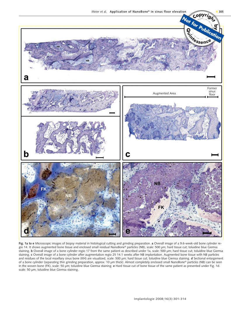
When taking the bone biopsies, we managed wit-hout difficulty to gain a long bone cylinder (Fig. 1a),when the newly created maxillary sinus floor was di-rectly above the end of the trephine. From time totime the drill cores remained firmly linked with theaugmented area through the small base of the cylin-der and had to be prepared separately which was dif-ficult because of the density of the bone and on theother hand on account of the necessity not to extendthe future implant bed. Some predrilled cylinderscould only be extracted in several segments (Fig. 1b),so that only sections shorter than the bone cores ofideally more than 10 mm could be examined.
When no well-preserved bone structure was gai-ned or the samples were excessively segmented onlymorphological but no histomorphometrical analysesof these biopsies could be performed. Thus 25 out ofthe 43 biopsies remained for quantitative evaluation.The numbers in table 2 refer to the consecutive num-bering of the samples. Bone cylinders of the originalalveolar process without squeezing artifacts were ob-tained in five samples only all others were excludedfrom the histomorphometrical examination due tothe irregular structure which had been created bypressing out fat marrow and the disturbance of thetrabecular architecture when removing it from thetrephine burs.
The augmented bone tissue showed signs of hy-perostosis in the form of broad, plump trabeculi thatconsisted of woven bone in the early stages. ResidualNanoBone® was found enclosed in de novo bone for-mations (Fig. 1a to c). The contact zone between theosteoblasts and the bone substitute showed a largeamount of osteoid (Fig. 2b to d) which partly infiltra-ted the NanoBone® particles. Furthermore cellularresorption by osteoclasts and macrophages is obser-ved on the surface of the NanoBone® particles.
A dense osteoblast lining with increased activityand broadening of the trabeculi’s diameter wasfound in the adjacent local bone as a result of the en-dosseous stimulation (Fig. 1b at the bottom). Afterlonger healing periods hyperostosis increased as wellin the bone as in the augmentation material (Fig.1c).
Table 2 gives an overview of the variety of the fin-dings. First of all the average portion of the bone areaof 37.7% in the augmentation material exceeds theone in the local alveolar process by 3%. The predo-minantly incorporated NanoBone® portion (NB) of anaverage of 19.3% adds to that figure which explainsthe remarkable increase in the bone density. The partof the medullary space is reduced and now amountsto an average of 43% which is approximately onethird less then in the local alveolar process with66.1% in average.
The volume of NanoBone® in the total crosssection reduces in time which can be demonstratedin samples taken after prolonged periods. When NanoBone® is mixed with blood in the recommendedratio of 3 : 2 in volume the histomorphometrical ana-lysis yielded 39.7% NB and 60.3% for the coagulum.
Implantologie 2008;16(3):301-314
304 � Meier et al. Application of NanoBone® in sinus floor elevation
Copyrig
ht
by
N
otfor
Qu
in
tessence
Not
forPublication
Implantologie 2008;16(3):301-314
� 305Meier et al. Application of NanoBone® in sinus floor elevation
Fig. 1a to e Microscopic images of biopsy material in histological cutting and grinding preparation. a Overall image of a 9.6-week-old bone cylinder re-gio 14. It shows augmented bone tissue and enclosed small residual NanoBone® particles (NB), scale: 500 µm; hard tissue cut; toluidine blue Giemsastaining. b Overall image of a bone cylinder regio 17 from the same patient as described under 1a, scale: 500 µm; hard tissue cut; toluidine blue Giemsastaining. c Overall image of a bone cylinder after augmentation regio 25 14.1 weeks after NB implantation. Augmented bone tissue with NB particlesand residues of the local maxillary sinus bone (KH) are visualized, scale: 500 µm; hard tissue cut; toluidine blue Giemsa staining. d Sectional enlargementof a bone cylinder (separating thin grinding preparation, approx. 10 µm thick). Almost completely enclosed small NanoBone® particles (NB) can be seenin the woven bone (FK), scale: 50 µm; toluidine blue Giemsa staining. e Hard tissue cut of bone tissue of the same patient as presented under Fig. 1d.scale: 50 µm; toluidine blue Giemsa staining.
Augmented Area
Formersinusfloor
Copyrig
ht
by
N
otfor
Qu
in
tessence
Not
forPublication
Taking into consideration the variation of the mea-sured ratios and the small number of samples analy-zed in this study we can only state that the meancompartment of NB in this material has decreased to19.3% .
The reduction in the NB portion can be explainedas the consequence of the degradation of the bonesubstitute. Only approximately 50% of the initiallyinserted augmentation material was still present af-ter two to three months.
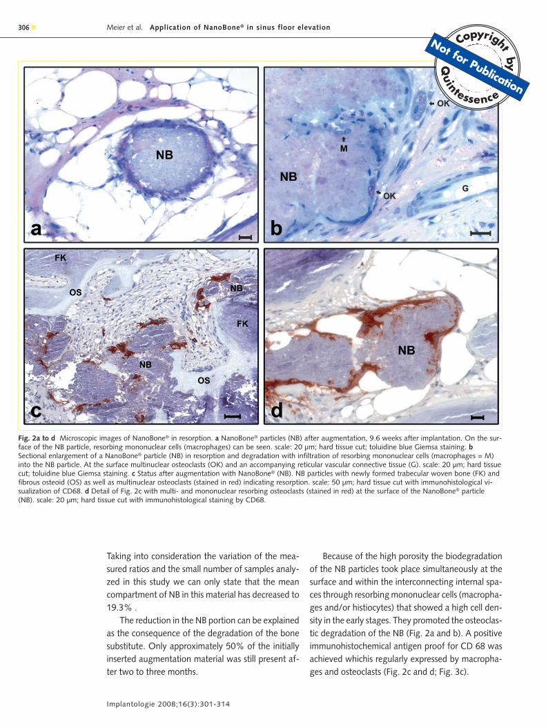
Because of the high porosity the biodegradationof the NB particles took place simultaneously at thesurface and within the interconnecting internal spa-ces through resorbing mononuclear cells (macropha-ges and/or histiocytes) that showed a high cell den-sity in the early stages. They promoted the osteoclas-tic degradation of the NB (Fig. 2a and b). A positiveimmunohistochemical antigen proof for CD 68 wasachieved whichis regularly expressed by macropha-ges and osteoclasts (Fig. 2c and d; Fig. 3c).
Implantologie 2008;16(3):301-314
306 � Meier et al. Application of NanoBone® in sinus floor elevation
Fig. 2a to d Microscopic images of NanoBone® in resorption. a NanoBone® particles (NB) after augmentation, 9.6 weeks after implantation. On the sur-face of the NB particle, resorbing mononuclear cells (macrophages) can be seen. scale: 20 µm; hard tissue cut; toluidine blue Giemsa staining. bSectional enlargement of a NanoBone® particle (NB) in resorption and degradation with infiltration of resorbing mononuclear cells (macrophages = M)into the NB particle. At the surface multinuclear osteoclasts (OK) and an accompanying reticular vascular connective tissue (G). scale: 20 µm; hard tissuecut; toluidine blue Giemsa staining. c Status after augmentation with NanoBone® (NB). NB particles with newly formed trabecular woven bone (FK) andfibrous osteoid (OS) as well as multinuclear osteoclasts (stained in red) indicating resorption. scale: 50 µm; hard tissue cut with immunohistological vi-sualization of CD68. d Detail of Fig. 2c with multi- and mononuclear resorbing osteoclasts (stained in red) at the surface of the NanoBone® particle(NB). scale: 20 µm; hard tissue cut with immunohistological staining by CD68.
Copyrig
ht
by
N
otfor
Qu
in
tessence
Not
forPublication
Implantologie 2008;16(3):301-314
� 307Meier et al. Application of NanoBone® in sinus floor elevation
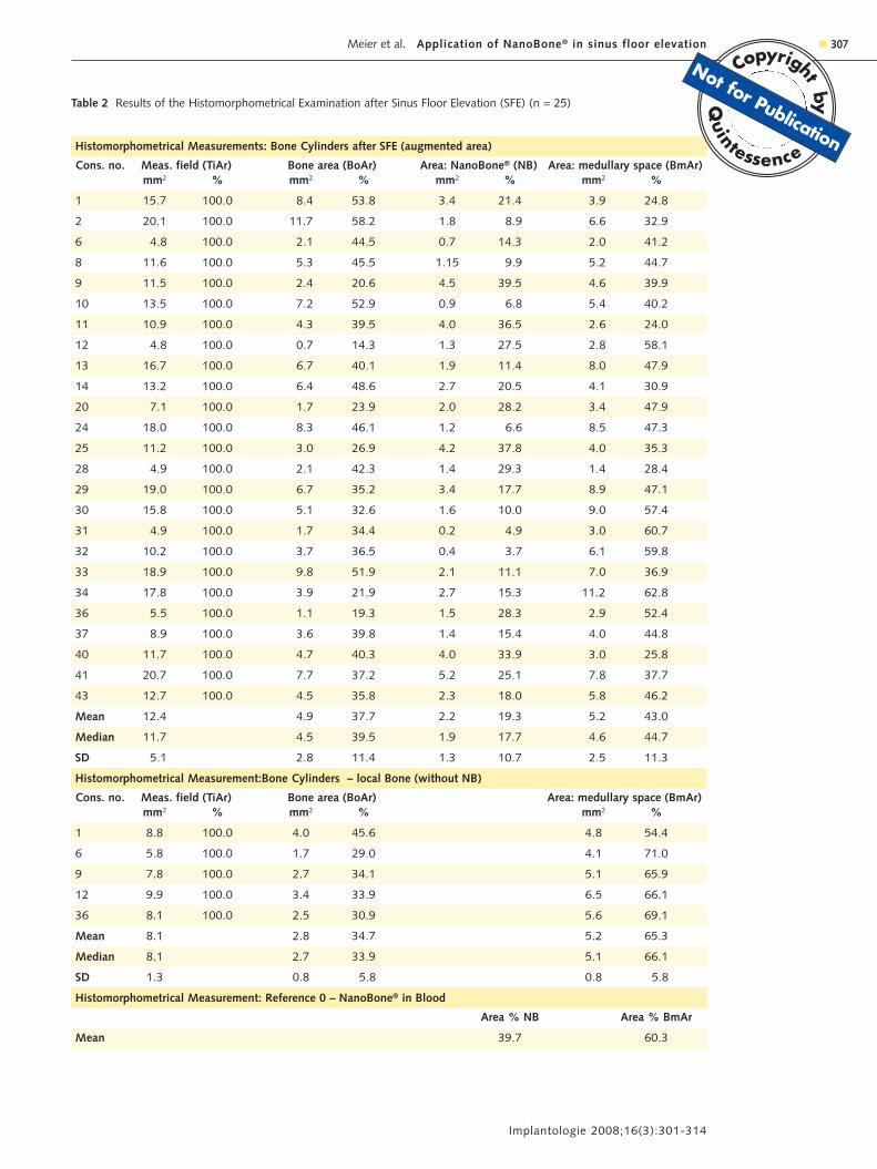
Table 2 Results of the Histomorphometrical Examination after Sinus Floor Elevation (SFE) (n = 25)
Histomorphometrical Measurements: Bone Cylinders after SFE (augmented area)
Cons. no. Meas. field (TiAr) Bone area (BoAr) Area: NanoBone® (NB) Area: medullary space (BmAr)mm2 % mm2 % mm2 % mm2 %
1 15.7 100.0 8.4 53.8 3.4 21.4 3.9 24.8
2 20.1 100.0 11.7 58.2 1.8 8.9 6.6 32.9
6 4.8 100.0 2.1 44.5 0.7 14.3 2.0 41.2
8 11.6 100.0 5.3 45.5 1.15 9.9 5.2 44.7
9 11.5 100.0 2.4 20.6 4.5 39.5 4.6 39.9
10 13.5 100.0 7.2 52.9 0.9 6.8 5.4 40.2
11 10.9 100.0 4.3 39.5 4.0 36.5 2.6 24.0
12 4.8 100.0 0.7 14.3 1.3 27.5 2.8 58.1
13 16.7 100.0 6.7 40.1 1.9 11.4 8.0 47.9
14 13.2 100.0 6.4 48.6 2.7 20.5 4.1 30.9
20 7.1 100.0 1.7 23.9 2.0 28.2 3.4 47.9
24 18.0 100.0 8.3 46.1 1.2 6.6 8.5 47.3
25 11.2 100.0 3.0 26.9 4.2 37.8 4.0 35.3
28 4.9 100.0 2.1 42.3 1.4 29.3 1.4 28.4
29 19.0 100.0 6.7 35.2 3.4 17.7 8.9 47.1
30 15.8 100.0 5.1 32.6 1.6 10.0 9.0 57.4
31 4.9 100.0 1.7 34.4 0.2 4.9 3.0 60.7
32 10.2 100.0 3.7 36.5 0.4 3.7 6.1 59.8
33 18.9 100.0 9.8 51.9 2.1 11.1 7.0 36.9
34 17.8 100.0 3.9 21.9 2.7 15.3 11.2 62.8
36 5.5 100.0 1.1 19.3 1.5 28.3 2.9 52.4
37 8.9 100.0 3.6 39.8 1.4 15.4 4.0 44.8
40 11.7 100.0 4.7 40.3 4.0 33.9 3.0 25.8
41 20.7 100.0 7.7 37.2 5.2 25.1 7.8 37.7
43 12.7 100.0 4.5 35.8 2.3 18.0 5.8 46.2
Mean 12.4 4.9 37.7 2.2 19.3 5.2 43.0
Median 11.7 4.5 39.5 1.9 17.7 4.6 44.7
SD 5.1 2.8 11.4 1.3 10.7 2.5 11.3
Histomorphometrical Measurement:Bone Cylinders – local Bone (without NB)
Cons. no. Meas. field (TiAr) Bone area (BoAr) Area: medullary space (BmAr)mm2 % mm2 % mm2 %
1 8.8 100.0 4.0 45.6 4.8 54.4
6 5.8 100.0 1.7 29.0 4.1 71.0
9 7.8 100.0 2.7 34.1 5.1 65.9
12 9.9 100.0 3.4 33.9 6.5 66.1
36 8.1 100.0 2.5 30.9 5.6 69.1
Mean 8.1 2.8 34.7 5.2 65.3
Median 8.1 2.7 33.9 5.1 66.1
SD 1.3 0.8 5.8 0.8 5.8
Histomorphometrical Measurement: Reference 0 – NanoBone® in Blood
Area % NB Area % BmAr
Mean 39.7 60.3
Copyrig
ht
by
N
otfor
Qu
in
tessence
Not
forPublication
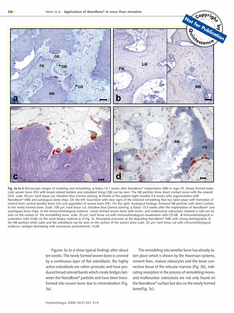
Figures 3a to d show typical findings after aboutten weeks: The newly formed woven bone is coveredby a continuous layer of flat osteoblasts; the highlyactive osteoblasts are rather prismatic and have pro-duced broad osteoid bands which create bridges bet-ween the NanoBone® particles and have been trans-formed into woven bone due to mineralization (Fig.3a).
The remodeling into lamellar bone has already ta-ken place which is shown by the Haversian systems,cement lines, mature osteocytes and the loose con-nective tissue of the reticular marrow (Fig. 3b). Indi-cating resorption in the process of remodeling mono-and multinuclear osteoclasts are not only found onthe NanoBone® surface but also on the newly formedbone(Fig. 3c).
Implantologie 2008;16(3):301-314
308 � Meier et al. Application of NanoBone® in sinus floor elevation
Fig. 3a to d Microscopic images of modeling and remodeling. a Status 14.1 weeks after NanoBone® implantation (NB) in regio 25. Newly formed trabe-cular woven bone (FK) with broad osteoid borders and osteoblast lining (OB) can be seen. The NB particles show direct contact zones with the osteoid(OS). scale: 50 µm; hard tissue cut; toluidine blue Giemsa staining. b Details of the patient (right maxilla) 9.6 weeks after augmentation withNanoBone® (NB) and autologous bone chips. On the left: local bone with clear signs of the endostal remodeling that has taken place with formation ofcement lines, central lamellar bone (LK) and apposition of woven bone (FK). On the right: Analogical findings: Enclosed NB particles with direct contactto the newly formed bone. Scale: 100 µm; hard tissue cut; toluidine blue Giemsa staining. c Status 13.9 weeks after the implantation of NanoBone® andautologous bone chips. In the immunohistological evidence newly formed woven bone with mono- and multinuclear osteoclasts (stained in red) can beseen on the surface of the remodelling bone, scale: 20 µm; hard tissue cut with immunohistological visualization with CD 68. d Immunohistological vi-sualization with Vs38c on the same biopsy material as in Fig. 3c. Resorptive processes at the degrading NanoBone® (NB) with strong disintegration ofthe NB particles while cubic and flat osteoblasts can be seen on the surface of the woven bone scale: 20 µm; hard tissue cut with immunohistologicalevidence, (antigen demasking with microwave pretreatment). Vs38.
Copyrig
ht
by
N
otfor
Qu
in
tessence
Not
forPublication
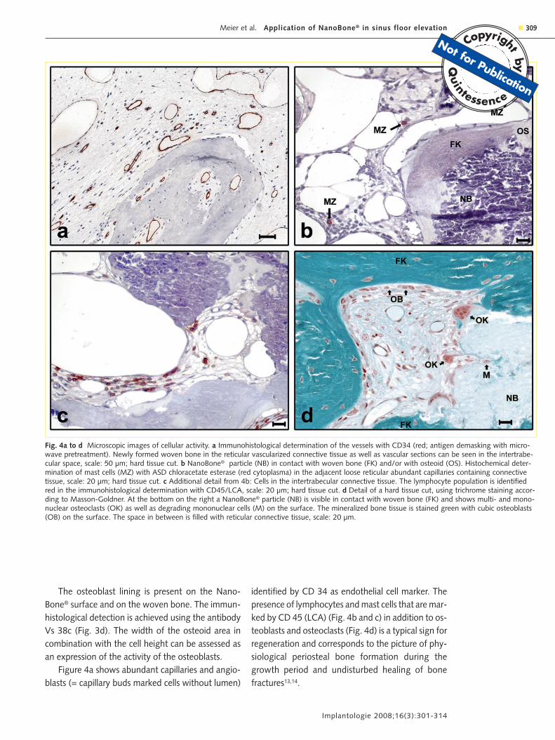
The osteoblast lining is present on the Nano-Bone® surface and on the woven bone. The immun-histological detection is achieved using the antibodyVs 38c (Fig. 3d). The width of the osteoid area incombination with the cell height can be assessed asan expression of the activity of the osteoblasts.
Figure 4a shows abundant capillaries and angio-blasts (= capillary buds marked cells without lumen)
identified by CD 34 as endothelial cell marker. Thepresence of lymphocytes and mast cells that are mar-ked by CD 45 (LCA) (Fig. 4b and c) in addition to os-teoblasts and osteoclasts (Fig. 4d) is a typical sign forregeneration and corresponds to the picture of phy-siological periosteal bone formation during thegrowth period and undisturbed healing of bonefractures13,14.
Implantologie 2008;16(3):301-314
� 309Meier et al. Application of NanoBone® in sinus floor elevation
Fig. 4a to d Microscopic images of cellular activity. a Immunohistological determination of the vessels with CD34 (red; antigen demasking with micro-wave pretreatment). Newly formed woven bone in the reticular vascularized connective tissue as well as vascular sections can be seen in the intertrabe-cular space, scale: 50 µm; hard tissue cut. b NanoBone® particle (NB) in contact with woven bone (FK) and/or with osteoid (OS). Histochemical deter-mination of mast cells (MZ) with ASD chloracetate esterase (red cytoplasma) in the adjacent loose reticular abundant capillaries containing connectivetissue, scale: 20 µm; hard tissue cut. c Additional detail from 4b: Cells in the intertrabecular connective tissue. The lymphocyte population is identifiedred in the immunohistological determination with CD45/LCA, scale: 20 µm; hard tissue cut. d Detail of a hard tissue cut, using trichrome staining accor-ding to Masson-Goldner. At the bottom on the right a NanoBone® particle (NB) is visible in contact with woven bone (FK) and shows multi- and mono-nuclear osteoclasts (OK) as well as degrading mononuclear cells (M) on the surface. The mineralized bone tissue is stained green with cubic osteoblasts(OB) on the surface. The space in between is filled with reticular connective tissue, scale: 20 µm.
Copyrig
ht
by
N
otfor
Qu
in
tessence
Not
forPublication
None of the samples showed inflammatory infil-trates or foreign-body reaction or a tight collagenousand poorly vascularized fiber formation like scar tis-sue or fibrous enclosure.
� Discussion
The generally accepted standards for bone substitu-tes and / or grafting materials include:
– no transmission of infections or other diseases– absence of allergizing components– good applicability– sufficient volume stability– osteoconductivity– complete resorbability with simultaneous repla-
cement by vital lamellar bone and– possibly an osteoinductive potential.
The material examined in this study meets these cri-teria. The first two requirements are met through thesynthetic origin and the use of nature-identical com-ponents (HA and SiO2). A good applicability is achie-ved by mixing it with venous blood (or blood col-lected from the site of augmentation) in the givenmixing ratio which results in a well moldable com-pound.
The augmentation material’s volume stability de-pends decisively on the resorption period and thenew bone formation which under ideal conditions ta-kes place simultaneously. The functional stimulus bythe early loading of the implants after only a relati-vely short integration period is decisive for volumepreservation. This prevents inactivity involution thathas been observed after augmentation with autoge-nous bone and long incorporation periods5,28. Thisobservation lead to the recommendation of perfor-ming an overcompensation by approx. 30% in thosecases. Because of the inconstant resorption of exces-sive autogenous bone this is not necessary at all if thefunctional loading takes place early and in accor-dance with bone physiology.
For NanoBone® complete resorption can be ex-pected after approximately nine months (unpublis-hed author’s data). During this period, the residualvolume of NanoBone® falls below 10% and new vi-tal bone is formed. After the initial period with for-mation of woven bone, the transformation into la-
mellar bone starts from the forth week on and thefunction-oriented structured remodeling begins afteranother eight to twelve weeks in case of prompt (af-ter eight to twelve weeks) implantation and functio-nal loading of the implants.
No loss of marginal or antral bone height was ob-served during the follow-up period of at leasteighteen months. This is confirmed by the findings ofrecall examinations and survey radiographs. Radio-graphic findings are only suitable for volume deter-mination but not for the assessment of the resorptionprogress or new bone formation since the Nano-Bone®-blood mixture and the regenerated bone donot really differ from natural bone on account of thegrain size and the calcium content.
All histological preparations show the good os-teoconductivity since the NanoBone® particles are inclose contact with the appositionally formed newbone and/or are enclosed in bone. The cellular colo-nization of the inside and outer surfaces and theearly and considerable vascularization are decisive forappositional osteogenesis. Similar to the healing ofbone fractures the immobilization of the augmenta-tion material is mandatory. This can easily be achie-ved in the maxillary sinus, at other sites this has to bedemanded as conditiosine qua non and where neces-sary to be ensured through a suitable coverage15.
It is under discussion whether NanoBone® can beconsidered to have an osteoinductive potential.Further studies will be carried out on this subject tosettle this question, but this is not part of this study.Nevertheless, the histological findings with a newbone formation that is found constantly throughoutthe entire cross section of the samples – not only“creeping substitution” from the neighbouringbone like other bone substitutes – suggest such pre-sumptions.
The principles for the filling of osseous defectswith autogenous bone transplants are standard me-thods and references for the use of bone substitutesin combination with implant therapy. Their main in-convenience consists of the donor-site morbidity andthe possibly limited availability. Nevertheless, thecomparison of the cellular processes in the trans-plantation of autogenous bone provides interestingparallelities to the augmentation using bone substi-tutes since the cascade of cellular reaction recurseverywhere. A characteristic feature of both the
Implantologie 2008;16(3):301-314
310 � Meier et al. Application of NanoBone® in sinus floor elevation
Copyrig
ht
by
N
otfor
Qu
in
tessence
Not
forPublication
transplantation of autogenous bone blocks and ofparticulate bone tissue reveals the fact that regene-ration takes place starting from the adjacent bone by“creeping substitution“ and also as new bone tissueis formed in the wake of vascularization with the re-sorption of the transplanted bone taking place simul-taneously. The same happens in case of the augmen-tation using NanoBone® with the analogous se-quence of cellular reactions like that after thetransplantation of autogenous cancellous bone.
The vascularized adjacent tissue always is thestarting point of the regeneration processes. Compa-ring NanoBone® with other bone substitutes diffe-rent features can be observed with regard to the pe-netration of the augmentation material with macro-phages and newly formed blood-vessels. Thisangiogenic new bone formation was described byRöser et al.29 for the augmentation with hydroxyapa-tite. Transplants made of cancellous bone blocks areossified within three to four months, transplantsmainly made of cortical blocks need nine to twelvemonths for complete osseous integration. A healingperiod corresponding to the latter (six to twelvemonths) is recommended for coralline bone substi-tute19, β-TCP20,28 and bovine bone matrix21,26,27.
In all cases new bone formation only takes placestarting from the border (creeping substitution).
Therefore, the angiogenic osteogenesis takingplace throughout the entire volume in NanoBone®
constitutes a true difference in quality. The compari-son with the regeneration periods of other bone sub-stitutes emphasizes the essentially faster new boneformation with NanoBone®: For β-TCP (e. g. Cera-sorb®; Curasan Ltd., Kleinostheim, Germany), an in-corporation period of nine to twelve months up tofifteen months is recommended before implanta-tion18,20,25,28 and a six to twelve months incorporationperiod is recommended for bone substitutes of bo-vine origin (e. g. BioOss®; Geistlich, Wolhusen, Swit-zerland)21,26,27; the time until loading of the implantswould add another six months.
Only a small number of papers is available in whichhistomorphometrical data have been published forthese bone substitutes after sinus floor elevations.Those show that 17 to 34% of newly formed bonewas found eight to twelve months after sinus floor ele-vations with bovine bone matrix21,26 and 17 to 38%after implantation of β-TCP20,28 after similar periods.
After sinus floor elevations with NanoBone® com-parable values are available after less than threemonths. The mean ratios found in this relatively smalltest group are:
– 37.7% for calcified bone (BoAr)– 43.0 % for bone narrow (BmAr) and– 19.3 % for residual NanoBone®
Our data show a considerable standard deviation(SD about 11%). Median values however show littledifferences:
– 39.5 % BoAr– 44.7 % BmAr and– 17.7 % for NB residues.
The relation between calcified bone and bone mar-row in the alveolar processus only shows a small de-viation and is approximately one to two thirds (34%vs. 66%) which corresponds to literature.
The fact that no substantial difference was foundin case of addition of autogenous bone (chips frombone collectors) is noteworthy but cannot be evalua-ted statistically – due to the small test group.The dif-ferentiation according to time of the sample col-lection between group 1 and 2 does not show anyreliable differences. This may result from the fact thatthe times of sampling did not differ much and the in-terindividual variables obscure possible differences.Studies including a larger number of cases are neces-sary to answer these questions.
Hydroxyapatite (HA) is the inorganic componentof bone. This is why the request for synthetic bonesubstitutes in the early 80’s resulted in the develop-ment of different bone substitutes based on HA gra-nules sintered at high-temperatures30,31. It’s most stri-king characteristic was the fact that new bone forma-tion was achieved under very special conditions only.In most cases only an invagination by connective tis-sue and at best the formation of a fibrous scar wasseen but most often sequestrations occurred even af-ter several years. For bone substitutes made of β-TCPof similar macrostructure the results are alike alt-hough presentations with new bone formationestablished this material as one of the current refe-rences for bone substitutes.
The disturbed, missing or delayed de novo boneformation for sintered hydroxylapatite or tricalciumphosphates can be explained by the lack of porosity
Implantologie 2008;16(3):301-314
� 311Meier et al. Application of NanoBone® in sinus floor elevation
Copyrig
ht
by
N
otfor
Qu
in
tessence
Not
forPublication
and the poor solubility and/or the lack of phagocy-tability of the HA macrocrystals. The disadvantage ofthe lack of porosity was avoided by using coralline orbovine bone substitutes. These preparations alsocontain HA macrocystals that are characterized byhigh stability and the resistance to resorption. This iswhy remnants of these bone substitutes are stillfound even after more than two years. Since foreignmaterial in the bone results in bypass structures32,33 ithas to be discussed whether this can be justified forachieving higher stability of the augmented volumeor offers functional advantages at all compared tothe naturally structured bone17,18 and has a relevantinfluence on the long-term success of implants.
After the transplantation of autogenous boneand complete ossification this is of identical biolo-gical value like the original bone. The same appliesto the status after augmentation with NanoBone®.The stability of the augmented volume here is notthe effect of the filler but the functional reqiuire-ments that are stimulating the bone around im-plants and natural teeth. Thus the correctly timedfunctional loading of the implants determine vo-lume as well as the trabecular structure of the newalveolar bone.
The cellular reactions after augmentation of thesinus using NanoBone® correspond to those of pri-mary healing after bone fractures32,33. No signs of aresorptive inflammation were found in the study’scollective. The cells responsible for osteogenesis aregenerated by the sessile periosteal and endossal stemcells of the recipient site and of circulating stem cellsand by angiogenesis. The latter is responsible for theimage of the neo-osteogenesis taking place almosthomogeneously throughout the entire cross section.
The nanocrystalline hydroxyapatite embedded inamorphic silica gel leads to a vast enlargement of theinternal surface which is attracting the precursors ofcellular regeneration through the adsorption ofthrombocytes, fibrinogen, complement factors andglycoproteins34-49 which explains the remarkably fas-ter angiogenesis and de novo bone formation com-pared to other bone substitutes. Since NanoBone®
gets substituted completely by natural bone duringprocess of remodelling calling it ‘bone augmentationmaterial‘ is justified.
The role of the silica gel that disappears comple-tely within two weeks after installation is subject to
ongoing studies (additional publication is being pre-pared).
� Conclusion
This nanostructured hydroxyapatite in a silica gel isan augmentation material that provides us with a sta-ble and reliable implant layer within only threemonths after sinus floor elevation .
� Acknowledgement
We would like to thank the following staff membersfor technical processing including the performance ofthe morphometric work: Ms H. Ahrens (MTA), Ms S.Franke (MHSc – NZ), Ms G. Hall (MTA), Dr. rer. nat.S. Lenz.
� References1. Gerber T, Holzhüter G, Götz W, Bienengräber V, Henkel K-
O, Rumpel E. Nanostructuring of biomaterials – A pathwayto bone grafting substitute. Eur J Trauma 2006;32:132-140.
2. Tatum OH. Maxillary sinus grafting for endosseous implants.Annual Meeting of the Alabama Implant Study Group:Birmingham, USA, 1977.
3. Boyne PJ, James RA. Grafting of the maxillary sinus floor withautogenous marrow and bone. J Oral Surg 1980;38: 613-616.
4. Wolf E. Technovit® 9100 NEU: Polymerisationssystem fürdie Einbettung von mineralisiertem Gewebe und Weich-gewebe zur histologischen, immun- und enzymhistochemi-schen Untersuchung einschließlich In-situ-Hybridisierung.Heraeus Kulzer, Hanau 2001.
5. Wolf E, Röser K, Hahn M, Welkerling H, Delling G. Enzymeand immunohistochemistry on undecalcified bone and bonemarrow biopsies after embedding in plastic: a new embed-ding method for routine application. Virchows Archiv APathol Anat Histopathol 1992;420:17-24.
6. Burkhardt R. Farbatlas der klinischen Histopathologie vonKnochenmark und Knochen. Berlin: Springer, 1970.
7. Schenk R, Olah A, Herrmann W. Preparation of calcified tis-sues for light microscopy: In: Dickson G (ed). Methods ofCalcified Tissue Preparation. Amsterdam – New York –Oxford: Elsevier, 1984:1-56.
8. Donath K. Preparation of histologic sections by the cutting-grinding technique for hard tissue and other material notsuitable to be sectioned by routine methods – Equipmentand methodical performance. Norderstedt: PublicationExakt-Kulzer, 1995.
9. Donath K. Die Trenn-Dünnschliff-Technik zur Herstellunghistologischer Präparate von nicht schneidbaren Gewebenund Materialien. Der Präparator 1988;34:197-206.
10. Parfitt AM, Drezner MK, Glorieux FH, Kanis JA, Malluche H,Meunier PJ, et al. Bone histomorphometry: standardizationof nomenclature, symbols, and units. Report of the ASBMRHistomorphometry Nomenclature Committee. J Bone MinRes 1987;2:595-610.
Implantologie 2008;16(3):301-314
312 � Meier et al. Application of NanoBone® in sinus floor elevation
Copyrig
ht
by
N
otfor
Qu
in
tessence
Not
forPublication
11. Merz W. Die Streckenmessung an gerichteten Strukturen imMikroskop und ihre Anwendung zur Bestimmung vonOberflächen-Volumen-Relationen im Knochengewebe.Mikroskopie 1967;22:132-142.
12. Lekholm U, Zarb G. Kieferanatomie: In: Brånemark I, ZarbG, Albrektson T (eds). Gewebeintegrierter Zahnersatz.Berlin: Quintessenz, 1985:198.
13. Schenk R, Willenegger H. Zum histologischen Bild der soge-nannten Primärheilung der Knochenkompakta nach experi-mentellen Osteotomien am Hund. Separatum Experientia1963;19:593-595.
14. Schenk R, Willenegger H. Zur Histologie der primärenKnochenheilung. Langenbecks Arch Klin Chir Ver Dtsch ZChir 1964;308:440-452.
15. Von Arx T, Hardt N, Wallkamm B, Kurt B. Die TIME-Technik:Lokale Osteoplastik zur Alveolarkammaugmentation –Auswertung und Ergebnisse der ersten 15 Fälle. Implan-tologie 1996;4:33-48.
16. Von Arx T, Cochran DL, Schenk RK, Buser D. Evaluation of aprototype trilayer membrane (PTLM) for lateral ridge aug-mentation: an experimental study in the canine mandible.Int J Oral Maxillofac Surg 2002;31:190-199.
17. Buser D, Ingimarsson S, Dula K, Lussi A, Hirt HP, Belser UC.Long-term stability of osseointegrated implants in augmen-ted bone: A 5-year prospective study in partially edentulouspatients. Int J Periodontics Restorative Dent 2002;22:108-117.
18. Buser D. Aus der Gefahren-Zone in die Komfort-Zone(Vortrag). EAO-Tagung:München, 2005.
19. Ewers R, Kasperk C, Simons B. Biologisches Knochen-implantat aus Meeresalgen. Zahnärztl Praxis 1987;38:319-324.
20. György S, Huys L, Coulthard P, Maiorana C, Garagiola U,Barabas J, et al. A prospective multicenter randomized clini-cal trial of autogenous bone versus β-tricalcium-phospategraft alone for bilateral sinus elevation. Histologic and histo-morphometric evaluation. Int J Oral Maxillofac Implants2005;20:371-381.
21. Hallman M, Sennerby L, Lundgren S. A clinical and histolo-gic evaluation of implant integration in the posterior maxillaafter sinus floor augmentation with autogenous bone, bovi-ne hydroxyapatite or a 20:80 mixture. Int J Oral MaxillofacImplants 2002;17:635-643.
22. Härle F. Augmentation with hydroxylapatite and vestibulo-plasty in the atrophic maxilla with a flabby ridge. JMaxillofac Surg 1985;13:209-212.
23. Haessler D, Fürst U, Foitzik C. Implantatversorgung des teil-bezahnten Gebisses nach Extension und Augmentation desKieferkamms durch freie autogene Knochentransplantation.Quintessenz 1994;45:645-652.
24. Maas W, Bienengraeber V, Wolf E. Sicher augmentieren –Split-mouth-Fallstudie zur Augmentation mittelgroßerKnochendefekte. Implantologie Journal 2006;5:40-44.
25. Terheyden H. Knochenzüchtung – geht das? (Vortrag).Jahrestagung DGI, München, 2007.
26. Valentini P, Abensur D, Wenz B, Peetz M, Schenk R. Sinusgrafting with porous bone mineral (Bio-Oss) for implant pla-cement: A 5-year study on 15 patients. Int J PeriodonticsRestorative Dent 2000;20:245-253.
27. Wallace SS, Froum SJ, Cho SC, Elian N, Monteiro D, Kim BS,et al. Sinus augmentation utilizing anorganic bovine bone(BioOss) with absorbable and nonabsorbable membranesplaced over the lateral window: Histomorphometric and cli-nical analysis. Int J Periodontics Restorative Dent 2005;25:551-559.
28. Zijderveld SA, Zerbo IR, van den Bergh JP, Schulten EA, tenBrugenkate CM. Maxillary sinus floor augmentation using a
β-tricalcium phosphate (Cerasorb) alone compared to auto-genous bone grafts. Int J Oral Maxillofac Implants 2005;20:432-440.
29. Röser K, Donath K, Schnettler R. Histopathologische undhistochemische Untersuchung an unentkalkten Schliff-präparaten zur Knochendefektheilung unter Verwendung al-logener Transplantate und poröser Hydroxylapatitkeramik-Implantate. Osteosynthese International 1994;2:124-134.
30. Osborn JF. Die enossale Implantation von Hydroxyl-apatitkeramik unter Verwendung des Fibrinklebesystems.Dtsch Zahnärztl Z 1983;38:956-958.
31. Donath K, Hormann K, Kirsch A. Welchen Einfluss hatHydroxylapatitkeramik auf die Knochenbildung? Dtsch ZMund Kiefer Gesichtschir 1985;9:438-440.
32. Schenk R, Willenegger H. Zur Histologie der primärenKnochenheilung. Modifikation und Grenzen der Spalthei-lung in Abhängigkeit von der Defektgröße. Unfallheilkunde1977;80:155-160.
33. Schenk R. Die Histologie der primären Knochenheilung imLichte neuer Konzeptionen über den Knochenumbau.Unfallheilkunde 1978;81:219-227.
34. Friedenstein A (Hrsg). Determined and Inducible OsteogenicPrecursor Cells. Amsterdam: Elsevier, 1973.
35. Friedenstein A. Precursor cells of mechanocytes. Int RevCytol 1976;47:327-359.
36. Friedenstein AJ, Chailakhyan RK, Gerasimov UV. Bone mar-row osteogenic stem cells: in vitro cultivation and transplan-tation in diffusion chambers. Cell Tissue Kinet 1987;20:263-272.
37. Owen M. The origin of bone cells in the postnatal organism.Arthritis & Rheumatism 1980;23:1073-1080.
38. Owen M, Cave J, Joyner C. Clonal analysis in vitro of osteo-genic differentiation of marrow CFU-F. J Cell Sci 1987;87:731-738.
39. Donath K, Laaß M, Günzl H-J. The histopathology of diffe-rent foreign-body reactions in oral soft tissue and bone tis-sue. Virchows Archiv A Pathol Anat Histopathol 1992;420:131-137.
40. Vroman L, Adams AL, Klings M. Interactions among humanblood proteins at interfaces. Federation Proceedings 1971;30:1494-1502.
41. Hartwig BA, Lohman RE, Hench LL. Morphology of poly-peptide adsorption on ceramic substrates. Am Ceram SocBull 1973;52:430.
42. Van Oss CJ. Phagocytosis as a surface phenomenon. AnnRev Microbiol 1978;32:19-39.
43. Klein CPAT, de Groot K, Vermeiden JPW, van Kamp G.Interaction of some serum proteins with hydroxylapatite andother materials. J Biomed Mater Res 1980;14:705-712.
44. Chambers IJ. The response of the macrophage to foreignmaterial: In: Williams DF (ed): Fundamental Aspects ofBiocompatibility. Boca Raton Florida: CRC Press, 1981:145-158.
45. Hoffman AS. Principles governing biomolecule interactionsat foreign interfaces. J Biomed Mater Res 1974;8:77-83.
46. Taylor AC. Adhesion of cells to surfaces: In: Manly RS (ed):Adhesion in Biological Systems. New York: Academic Press,1970:51-71.
47. Sakamato S, Sakamato M. Bone collagenase, osteoblastsand cell-mediated bone resorption. In: Peck W (ed). Boneand Mineral Research. Amsterdam – New York – Oxford:Elsevier, 1986:49-102.
48. Frost H. The Bone Dynamics in Osteoporosis and Osteo-malacia. Springfield, USA: Thomas, 1966.
49. Rassmussen H, Bordier P. The physiological and cellular ba-sis of metabolic bone disease. Baltimore: Williams & Wilkins,1974.
Implantologie 2008;16(3):301-314
� 313Meier et al. Application of NanoBone® in sinus floor elevation
Copyrig
ht
by
N
otfor
Qu
in
tessence
Not
forPublication

![arXiv:2001.00702v2 [cs.CV] 23 Jan 2020arXiv:2001.00702v2 [cs.CV] 23 Jan 2020 method based on MANO [Romero etal., 2017]. Because syn-thetic images do not correspond exactly to real](https://img.pdfslide.us/doc/110x75/601b13192438884114105274/arxiv200100702v2-cscv-23-jan-2020-arxiv200100702v2-cscv-23-jan-2020-method.jpg)