Embed Size (px)
Citation preview
Selected Technique
1Biomedicasity, 2-1 Seiryo
2InstituteAoba, Sendai
CorrespondResearch Orga980-8575, Jap
Ann Vasc SurgDOI: 10.1016/� Annals of VPublished onli
Application of Shape Memory AlloyPressure-Controlled Vascular Clampfor Atraumatic Vessel Occlusion
Ye Zhang,1 Yun Luo,1 Shingo Kodaira,2 and Toshiyuki Takagi,2 Sendai, Japan
Background: To realize atraumatic vessel occlusion, a new hemostatic clamp using superelas-tic shape memory alloy (SMA) as a pressure control limiter has been proposed. It was designedtaking advantage of a unique mechanical property of SMA. The ability to control pressure withthe newly designed SMA clamp was investigated. The traumatic effect on vessel walls was eval-uated in order to confirm the SMA clamp’s biological effect of protecting vessels from damage.Methods: Twenty-four pig thoracic aortas were divided into four groups: SMA group 1 (0.3 mmdiameter SMA wire used), SMA group 2 (0.4 mm diameter SMA wire used), base model group(hemostatic clamp of Mimura type), and a control group. The biomechanical interaction betweenthe pressure-controlled clamp and animal aortas was evaluated with a micropressure analyzingsystem. The atraumatic effect of the SMA clamp was examined on pig thoracic aortas in vitro andcompared with that of its base model. The morphological injury of each vessel was evaluatedafter being clamped for 15 min.Results: Pressure saturation was shown in the displacementepressure curve of the SMAclamp. In both SMA group 1 and SMA group 2, except for a slight imprint of compression inthe intima, no obvious injury was observed, while in the base model group the endothelial lacer-ation was observed when the clamp was closed to notch I. More serious injuries in the endothe-lial intima and media were observed when the clamp was closed to notches II and III.Conclusion: The effect of pressure-controlling SMA clamps on the in vitro vessel model wasevaluated. Histological observation and the traumatic score proved that the safety of the clampswas improved with the new design of pressure control. This technique supplies an effective andapplicable way of realizing atraumatic clamping.
INTRODUCTION
The clamp technique is essential in any surgical
operation.1 Clamps are used to arrest bleeding and
to control blood flow from the arteries. They are
also used to ensure a clear surgical view through
temporary local vascular control in order to favor-
ably accomplish operations. This is achieved by
l Engineering Research Organization, Tohoku Univer-, Aoba, Sendai 980-8575, Japan.
of Fluid Science, Tohoku University, 2-2-1 Katahira,980-8577, Japan.
ence to: Ye Zhang, MD, Biomedical Engineeringnization, Tohoku University, 2-1 Seiryo, Aoba, Sendaian, E-mail: [email protected]
2009; 23: 813-820j.avsg.2009.06.001ascular Surgery Inc.ne: September 11, 2009
either cross- or lateral clamping.2 However, clamps
may also cause moderate to severe damage to the
vessel wall. Injuries caused by incorrect use of
clamps have been reported in several articles.3,4
Coelh et al.,4 using arteriographic and ultrasonic
evaluation, showed that the proportion of intimal
tears and flaps will reach 26% in some cases.
Atraumatic technique is an important issue in
surgery. Since Guthrie suggested its importance in
1903, many kinds of atraumatic clamps, such as Sat-
insky and De Bakey, have been invented.5 Although
these clamps have been widely used, they could not
fully meet the demand of the atraumatic technique.
Dujovny et al.6 demonstrated that these ‘‘atrau-
matic clamps’’ may also cause considerable endo-
thelial damage, which is proportional to the
‘‘closure force’’ applied. Injuries of vessels could be
minimized when force was controlled by closing to
813

Fig. 1. The newly designed pressure-controlled clamp
and SMA wires. The SMA wire was embedded in one
handling branch of the clamp with an additional fulcrum.
The wire and fulcrum formed a pressure-control
structure.
814 Zhang et al. Annals of Vascular Surgery
the minimal occlusive force (MOF),6,7 which refers
to the force applied that barely occludes the vessel.
Many improvements on pressure controlling have
proved that effective control of clamping pressure can
improve safety. For example, Darcin et al.2 invented
an atraumatic occluding clamp using a percutaneous
transluminal coronary angioplasty balloon combined
with a real-time pressure monitor. Other methods,
such as the use of silastic rubber,5,8 have also been
proposed; however, because of complication or
imprecision, those methods could not be practically
used or generally accepted.
Lack of an effective and consistent method for
pressure control impedes the improvement of
clamps. To create an atraumatic clamp that reduces
vessel injuries, the design can usually be improved
by two aspects of the clamp: the structure and the
material. Improvement on the structure has been
widely adopted, such as changes in the architecture
of the jaw face and the clamp geometry.9
On the other hand, the basic structure of the
clamp, a lever, allows the displacement of the
handle and the pressure of the jaw to show an expo-
nential relation when using general materials.10
With this basic structure, controlling pressure
becomes quite difficult. Because of the restrictions
of the material, it is not easy using only improve-
ments in the structure to realize an ‘‘atraumatic’’
technique. Selecting a new material which facili-
tates pressure controlling may be helpful to improve
the atraumatic ability of clamps.
Shape memory alloy (SMA) is an excellent bioma-
terial thathasbeenwidely used inclinical settings.11,12
SMA has the advantage of stress saturation.13 In order
to improve clamping safety, Luo et al13 proposed
taking advantage of this property to control the
closure pressure of clamps. The proposal is to embed
superelastic SMA wire into conventional hemostatic
clamps. Such a design, based on the unique mechan-
ical property of SMA, will limit the pressure between
the clamping jaws during its stress-induced transfor-
mation. The stress reaction of SMA wire has been
analyzed in our previous study.13 In this article, the
ability to control pressure with the newly designed
SMA clamp was investigated using an in vitro vessel
model. The traumatic effect on vessel walls was eval-
uated in order to confirm the SMA clamp’s biological
effect of protecting vessels from damage.
MATERIALS AND METHODS
SMA Pressure-Controlled Clamp
The basic concept of the new hemostatic clamps is to
ensure that the clamping pressure remains within
a safe range through an additional limiter made of
the superelastic wire of SMA. In addition to supere-
lastic and shape memory, some kinds of SMA mate-
rial have another phenomenon: With increasing
force, those SMAs reveal stress-induced transforma-
tion, during which the material shows a constant
stress for further extension.13,14 This is called stress
saturation.13
In the new design (Fig. 1), the SMA wire serves as
a stress limiter. It is embedded in one handling branch
of the clamp with an additional fulcrum. Thus, when
the clamp is quickly closed, the SMA wire is elon-
gated. With the transformation, the SMA wire is
elongated to cross a critical point. After reaching the
critical point, stress saturation will be present and
the pressure remains constant. Further displacement
of the handling rings does not increase the pressure.
The improvement was realized on a conventional
base model of the clamp. The base model (Mimura
type; Mizuho Ikoh, Tokyo, Japan) has the following
dimensions: 50 mm in length of jaws and 180 mm in
total length. The additional fulcrum was set to
95 mm in distance from the tip of the jaw.
Biomechanical Characteristic of SMA
Wires and Clamps
To construct the pressure-controlled vessel clamp,
TiNi SMA with the Ni component of 55.98-
56.04% was used.13 The diameters of wires were
0.3 and 0.4 mm. The length of the SMA wire was
40 mm. The biomechanical characteristic of SMA
wires was tested using a universal tensile testing
machine (Instron 4505 Universal Machine; Instron,
Norwood, MA) with the procedure described previ-
ously.13 The tensile test was performed with rates of
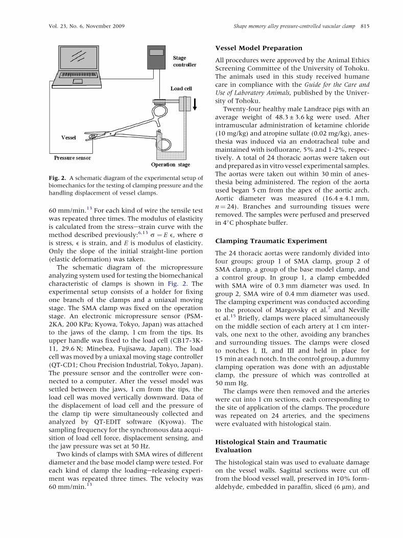
Fig. 2. A schematic diagram of the experimental setup of
biomechanics for the testing of clamping pressure and the
handling displacement of vessel clamps.
Vol. 23, No. 6, November 2009 Shape memory alloy pressure-controlled vascular clamp 815
60 mm/min.13 For each kind of wire the tensile test
was repeated three times. The modulus of elasticity
is calculated from the stressestrain curve with the
method described previously:6,13 s ¼ E e, where sis stress, e is strain, and E is modulus of elasticity.
Only the slope of the initial straight-line portion
(elastic deformation) was taken.
The schematic diagram of the micropressure
analyzing system used for testing the biomechanical
characteristic of clamps is shown in Fig. 2. The
experimental setup consists of a holder for fixing
one branch of the clamps and a uniaxal moving
stage. The SMA clamp was fixed on the operation
stage. An electronic micropressure sensor (PSM-
2KA, 200 KPa; Kyowa, Tokyo, Japan) was attached
to the jaws of the clamp, 1 cm from the tips. Its
upper handle was fixed to the load cell (CB17-3K-
11, 29.6 N; Minebea, Fujisawa, Japan). The load
cell was moved by a uniaxal moving stage controller
(QT-CD1; Chou Precision Industrial, Tokyo, Japan).
The pressure sensor and the controller were con-
nected to a computer. After the vessel model was
settled between the jaws, 1 cm from the tips, the
load cell was moved vertically downward. Data of
the displacement of load cell and the pressure of
the clamp tip were simultaneously collected and
analyzed by QT-EDIT software (Kyowa). The
sampling frequency for the synchronous data acqui-
sition of load cell force, displacement sensing, and
the jaw pressure was set at 50 Hz.
Two kinds of clamps with SMA wires of different
diameter and the base model clamp were tested. For
each kind of clamp the loadingereleasing experi-
ment was repeated three times. The velocity was
60 mm/min.13
Vessel Model Preparation
All procedures were approved by the Animal Ethics
Screening Committee of the University of Tohoku.
The animals used in this study received humane
care in compliance with the Guide for the Care and
Use of Laboratory Animals, published by the Univer-
sity of Tohoku.
Twenty-four healthy male Landrace pigs with an
average weight of 48.3 ± 3.6 kg were used. After
intramuscular administration of ketamine chloride
(10 mg/kg) and atropine sulfate (0.02 mg/kg), anes-
thesia was induced via an endotracheal tube and
maintained with isofluorane, 5% and 1-2%, respec-
tively. A total of 24 thoracic aortas were taken out
and prepared as in vitro vessel experimental samples.
The aortas were taken out within 30 min of anes-
thesia being administered. The region of the aorta
used began 5 cm from the apex of the aortic arch.
Aortic diameter was measured (16.4 ± 4.1 mm,
n¼ 24). Branches and surrounding tissues were
removed. The samples were perfused and preserved
in 4�C phosphate buffer.
Clamping Traumatic Experiment
The 24 thoracic aortas were randomly divided into
four groups: group 1 of SMA clamp, group 2 of
SMA clamp, a group of the base model clamp, and
a control group. In group 1, a clamp embedded
with SMA wire of 0.3 mm diameter was used. In
group 2, SMA wire of 0.4 mm diameter was used.
The clamping experiment was conducted according
to the protocol of Margovsky et al.7 and Neville
et al.15 Briefly, clamps were placed simultaneously
on the middle section of each artery at 1 cm inter-
vals, one next to the other, avoiding any branches
and surrounding tissues. The clamps were closed
to notches I, II, and III and held in place for
15 min at each notch. In the control group, a dummy
clamping operation was done with an adjustable
clamp, the pressure of which was controlled at
50 mm Hg.
The clamps were then removed and the arteries
were cut into 1 cm sections, each corresponding to
the site of application of the clamps. The procedure
was repeated on 24 arteries, and the specimens
were evaluated with histological stain.
Histological Stain and Traumatic
Evaluation
The histological stain was used to evaluate damage
on the vessel walls. Sagittal sections were cut off
from the blood vessel wall, preserved in 10% form-
aldehyde, embedded in paraffin, sliced (6 mm), and
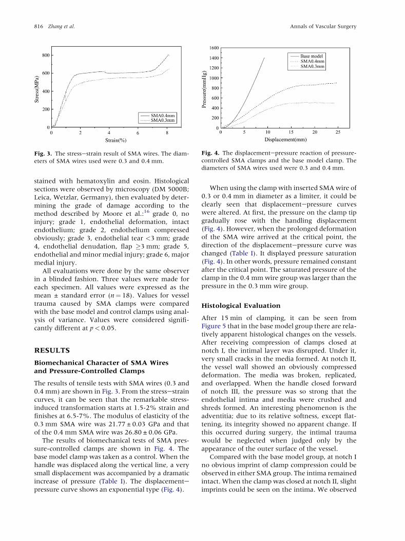
Fig. 3. The stressestrain result of SMA wires. The diam-
eters of SMA wires used were 0.3 and 0.4 mm.
Fig. 4. The displacementepressure reaction of pressure-
controlled SMA clamps and the base model clamp. The
diameters of SMA wires used were 0.3 and 0.4 mm.
816 Zhang et al. Annals of Vascular Surgery
stained with hematoxylin and eosin. Histological
sections were observed by microscopy (DM 5000B;
Leica, Wetzlar, Germany), then evaluated by deter-
mining the grade of damage according to the
method described by Moore et al.:16 grade 0, no
injury; grade 1, endothelial deformation, intact
endothelium; grade 2, endothelium compressed
obviously; grade 3, endothelial tear <3 mm; grade
4, endothelial denudation, flap �3 mm; grade 5,
endothelial and minor medial injury; grade 6, major
medial injury.
All evaluations were done by the same observer
in a blinded fashion. Three values were made for
each specimen. All values were expressed as the
mean ± standard error (n¼ 18). Values for vessel
trauma caused by SMA clamps were compared
with the base model and control clamps using anal-
ysis of variance. Values were considered signifi-
cantly different at p< 0.05.
RESULTS
Biomechanical Character of SMA Wires
and Pressure-Controlled Clamps
The results of tensile tests with SMA wires (0.3 and
0.4 mm) are shown in Fig. 3. From the stressestrain
curves, it can be seen that the remarkable stress-
induced transformation starts at 1.5-2% strain and
finishes at 6.5-7%. The modulus of elasticity of the
0.3 mm SMA wire was 21.77 ± 0.03 GPa and that
of the 0.4 mm SMA wire was 26.80 ± 0.06 GPa.
The results of biomechanical tests of SMA pres-
sure-controlled clamps are shown in Fig. 4. The
base model clamp was taken as a control. When the
handle was displaced along the vertical line, a very
small displacement was accompanied by a dramatic
increase of pressure (Table I). The displacementepressure curve shows an exponential type (Fig. 4).
When using the clamp with inserted SMA wire of
0.3 or 0.4 mm in diameter as a limiter, it could be
clearly seen that displacementepressure curves
were altered. At first, the pressure on the clamp tip
gradually rose with the handling displacement
(Fig. 4). However, when the prolonged deformation
of the SMA wire arrived at the critical point, the
direction of the displacementepressure curve was
changed (Table I). It displayed pressure saturation
(Fig. 4). In other words, pressure remained constant
after the critical point. The saturated pressure of the
clamp in the 0.4 mm wire group was larger than the
pressure in the 0.3 mm wire group.
Histological Evaluation
After 15 min of clamping, it can be seen from
Figure 5 that in the base model group there are rela-
tively apparent histological changes on the vessels.
After receiving compression of clamps closed at
notch I, the intimal layer was disrupted. Under it,
very small cracks in the media formed. At notch II,
the vessel wall showed an obviously compressed
deformation. The media was broken, replicated,
and overlapped. When the handle closed forward
of notch III, the pressure was so strong that the
endothelial intima and media were crushed and
shreds formed. An interesting phenomenon is the
adventitia; due to its relative softness, except flat-
tening, its integrity showed no apparent change. If
this occurred during surgery, the intimal trauma
would be neglected when judged only by the
appearance of the outer surface of the vessel.
Compared with the base model group, at notch I
no obvious imprint of clamp compression could be
observed in either SMA group. The intima remained
intact. When the clamp was closed at notch II, slight
imprints could be seen on the intima. We observed

Tab
leI.
Cla
mpin
gpre
ssu
rean
dtr
au
mati
csc
ore
son
the
vess
el
wall
pro
du
ced
by
clam
ps
(n¼
18)
Pre
ssu
re(m
mH
g)
Tra
um
ati
csc
ore
Gro
ups
Notc
hI
Notc
hII
Notc
hII
Ip
aN
otc
hI
Notc
hII
Notc
hII
Ip
SM
A(0
.3m
m)
409.1
4±
69.6
7490.5
4±
69.6
7495.9
0±
74.2
20.9
50.5
0±
0.2
60.6
7±
0.2
30.7
2±
0.2
10.6
0
SM
A(0
.4m
m)
640.9
1±
84.7
7811.7
2±
140.4
5846.2
5±
159.2
10.7
90.8
3±
0.1
51.6
6±
0.2
31.8
3±
0.1
50.5
5
Base
model
1,0
16.4
3±
159.2
12,7
20.5
8±
192.3
74,6
00.3
2±
420.4
50.0
32.8
3±
0.1
54.6
7±
0.4
15.6
7±
0.5
20.0
07
Con
trol
50
50
50
0.2
2±
0.1
80.1
7±
0.1
50.2
2±
0.1
80.6
8
p0.0
15
b<
0.0
01
b<
0.0
01
b<
0.0
01
<0.0
01
<0.0
01
aC
om
pari
son
betw
een
notc
hII
an
dn
otc
hII
I.bC
om
pari
son
of
SM
Agro
up
1(0
.3m
m)
an
dSM
Agro
up
2(0
.4m
m)
wit
hbase
model
gro
up.
Vol. 23, No. 6, November 2009 Shape memory alloy pressure-controlled vascular clamp 817
that the elastic lamina structure on the media was
slightly compacted. When the clamps closed at the
notch III, the clamp imprint on the vessel wall
became more obvious. Because the force remained
in the safety range, the intima was preserved in
both groups. The continuity of the intima was not
disturbed or broken. Only mild compressions could
be seen on the elastic structure of the media. The
compressions found in group 1 (0.3 mm diameter
SMA) were less obvious than those in group 2
(0.4 mm diameter SMA). However, no other
distinct signs could be observed.
In the control group, the intima, media, and
adventitia remained intact (Fig. 5).
Traumatic Evaluation
The traumatic score and its relation to clamping
pressure are shown in Table I. It could be seen that
vessel trauma correlated with clamp pressure. The
scores of the SMA groups were lower than the score
of the base model group. On the other hand, in the
base model group, as the pressure increased, trau-
matic scores increased from 4.67 ± 0.41 at notch II
to 5.67 ± 0.52 at notch III. There was a significant
difference in scores. However, in the two SMA
groups, since the pressure at notch II and notch III
remained constant, the traumatic score did not
increase (Table I).
DISCUSSION
As a kind of shape-memory, superelastic, and
fatigue-resistant biomaterial, SMA has been used
in many minimally invasive surgery and diagnostic
applications, such as vessel stents11 and ortho-
dontic appliances.12 On the other hand, with the
component changed, some SMA materials have
another unique mechanical property, stress satura-
tion.14 Thus, it may be a useful material in those
circumstances in which controlling pressure is
important.
In our study, a pressure-controlled clamp using
SMA material was designed. First, it should be
understood whether this design could effectively
control the pressure put on vessels. An in vitro
vessel model of pig thoracic aorta was used for its
comparable size to that of humans. From the results
of the loadingedisplacement experiment (Fig. 4), it
could be seen that the pressure put on vessels by
base model clamps increased with the handle’s
displacement. The displacementepressure curve is
an exponential shape. In the SMA groups the rela-
tion was altered. There is an obvious ‘‘pressure
constant’’ on the displacementepressure curve,
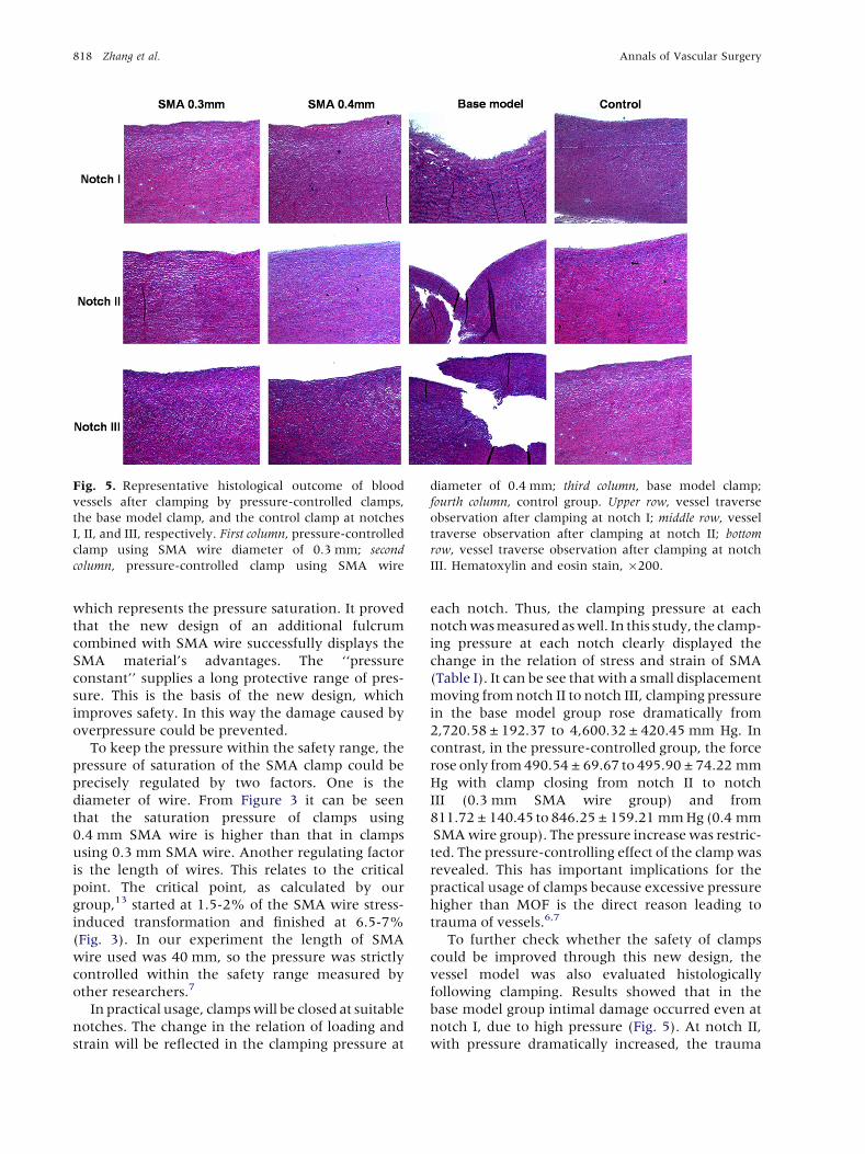
Fig. 5. Representative histological outcome of blood
vessels after clamping by pressure-controlled clamps,
the base model clamp, and the control clamp at notches
I, II, and III, respectively. First column, pressure-controlled
clamp using SMA wire diameter of 0.3 mm; second
column, pressure-controlled clamp using SMA wire
diameter of 0.4 mm; third column, base model clamp;
fourth column, control group. Upper row, vessel traverse
observation after clamping at notch I; middle row, vessel
traverse observation after clamping at notch II; bottom
row, vessel traverse observation after clamping at notch
III. Hematoxylin and eosin stain, �200.
818 Zhang et al. Annals of Vascular Surgery
which represents the pressure saturation. It proved
that the new design of an additional fulcrum
combined with SMA wire successfully displays the
SMA material’s advantages. The ‘‘pressure
constant’’ supplies a long protective range of pres-
sure. This is the basis of the new design, which
improves safety. In this way the damage caused by
overpressure could be prevented.
To keep the pressure within the safety range, the
pressure of saturation of the SMA clamp could be
precisely regulated by two factors. One is the
diameter of wire. From Figure 3 it can be seen
that the saturation pressure of clamps using
0.4 mm SMA wire is higher than that in clamps
using 0.3 mm SMA wire. Another regulating factor
is the length of wires. This relates to the critical
point. The critical point, as calculated by our
group,13 started at 1.5-2% of the SMA wire stress-
induced transformation and finished at 6.5-7%
(Fig. 3). In our experiment the length of SMA
wire used was 40 mm, so the pressure was strictly
controlled within the safety range measured by
other researchers.7
In practical usage, clamps will be closed at suitable
notches. The change in the relation of loading and
strain will be reflected in the clamping pressure at
each notch. Thus, the clamping pressure at each
notch was measured as well. In this study, the clamp-
ing pressure at each notch clearly displayed the
change in the relation of stress and strain of SMA
(Table I). It can be see that with a small displacement
moving from notch II to notch III, clamping pressure
in the base model group rose dramatically from
2,720.58 ± 192.37 to 4,600.32 ± 420.45 mm Hg. In
contrast, in the pressure-controlled group, the force
rose only from 490.54 ± 69.67 to 495.90 ± 74.22 mm
Hg with clamp closing from notch II to notch
III (0.3 mm SMA wire group) and from
811.72 ± 140.45 to 846.25 ± 159.21 mm Hg (0.4 mm
SMA wire group). The pressure increase was restric-
ted. The pressure-controlling effect of the clamp was
revealed. This has important implications for the
practical usage of clamps because excessive pressure
higher than MOF is the direct reason leading to
trauma of vessels.6,7
To further check whether the safety of clamps
could be improved through this new design, the
vessel model was also evaluated histologically
following clamping. Results showed that in the
base model group intimal damage occurred even at
notch I, due to high pressure (Fig. 5). At notch II,
with pressure dramatically increased, the trauma
Vol. 23, No. 6, November 2009 Shape memory alloy pressure-controlled vascular clamp 819
penetrated into the media. Shreds formed and
media folds could be observed. In contrast, in both
of the SMA groups, since the pressure was effec-
tively controlled, even at notch III only slight
compression could be seen in the sample of vessels.
The intima and media maintained integrity.
The innermost layer of blood vessels, the tunica
intima, is composed of a monolayer of endothelial
cells, the endothelium.17 Pabst et al.,5 using scan-
ning electron microscopy, proved that marked
endothelial fractures and intimal injury occurred
when vessels were clamped at a pressure higher
then MOF. The intimal lesion will be followed by
a pathological reaction such as fibrin deposition,
pseudoaneurysm formation,5 and embolization,
which could accelerate vessel injury.7,18 For this
reason, an intact intima is very important.
The relation between the score of trauma and the
force at each notch proved that it is due to the effec-
tive control of pressure that the difference in the
pathology was produced. This also shows the impor-
tance of controlling pressure for the safety of blood
vessels (Table I). Clamping pressure at notch I led
the base model clamp to cause trauma in vessel
walls. However, the trauma was within the intima.
As the handle moved to notch II and notch III, the
dramatically increased pressure caused the vessel
wall more serious trauma. The traumatic score
increased from 4.67 ± 0.41 at notch II to
5.67 ± 0.52 at notch III. This would bring serious
complications in clinical application. In the SMA
group, pressure increased moving from notch I to
notch II, leading the imprint in the vessel wall to
become more obvious. However, when the handle
moved from notch II to notch III, the pressure
remained constant. Thus, the score for damage on
vessel walls did not increase. This means that the
trauma caused by increased pressure in the control
group was avoided. This confirmed that the safety
of the clamp was improved.
The experiment was not in vivo, and some trau-
matic phenomena such as thrombin formation,
flow-induced shear stress, and reperfusion lesion
could not be analyzed. However, on the basis of
intimal lesions, this kind of pathological lesion would
certainly further accelerate vessel injury, which has
been proved by many other researchers.18,19
This experiment confirmed that the safety of the
base model improved with design improvement.
SMA plays a role by controlling the pressure of the
clamp. Certainly, the clamp is only a rough model.
The final design should take into account other
factors, such as jaw geometry, vessel size, systematic
blood pressure, and arterial wall elasticity. Other
special conditions, such as atherosclerotic arteries,
need to be considered as well. This technique should
be studied further.
Above all, this unique mechanical property was
effective at controlling clamp pressure. The new
design successfully improved the clamp’s safety.
This pressure-controlling method can be also used
in many related research areas, such as in the use
of endoscopes, computer simulation, and surgical
navigation.
CONCLUSIONS
The effect of pressure-controlling SMA clamps on
the in vitro vessel model was confirmed. Pressure
saturation was shown in the displacementepressure
curve. Occlusive pressure could be controlled in
a safe range.
Histological observation and the traumatic score
proved that the safety of clamps was improved
with the new design of pressure control.
This work was partially supported by the special coordination
funds for Promoting Science and Technology from the Ministry
of Education, Culture, Sports, Science, and Technology, Japan.
The authors thank Mizuho Ikoh Co. for assistance in prototyping.
REFERENCES
1. Gersak B, Trobec R, Krisch I, et al. Loss of endothelium-
mediated vascular relaxation as a response to various
clamping pressures. Eur J Cardiothorac Surg 1996;10:
684-689.
2. Darcin OT, Cengiz M, Ozardali I, et al. Pressure-controlled
vascular clamp: a novel device for atraumatic vessel occlu-
sion. Ann Vasc Surg 2004;18:254-256.
3. Margovsky AI, Lord RS, Meek AC, et al. Artery wall damage
and platelet uptake from so-called atraumatic arterial clamps:
an experimental study. Cardiovasc Surg 1997;5:42-47.
4. Coelho JC, Sigel B, Flanigan DP, et al. Arteriographic and ultra-
sonic evaluation of vascular clamp injuries using an in vitro
human experimental model. Surg Gynecol Obstet 1982;155:
506-512.
5. Pabst TS, 3rd, Flanigan DP, Buchbinder D. Reduced intimal
injury to canine arteries with controlled application of vessel
loops. J Surg Res 1989;47:235-241.
6. Dujovny M, Wakenhut N, Kossovsky N, et al. Minimum
vascular occlusive force. J Neurosurg 1979;51:662-668.
7. Margovsky AI, Chambers AJ, Lord RS. The effect of increasing
clamping forces on endothelial and arterial wall damage: an
experimental study in the sheep. Cardiovasc Surg 1999;7:
457-463.
8. Moore WM, Manship LL, Bunt TJ. Differential endothelial
injury caused by vascular clamps and vessel loops. I. Normal
vessels. Am Surg 1985;51:392-400.
9. Harvey JG, Gough MH. A comparison of the traumatic
effects of vascular clamps. Br J Surg 1981;68:267-272.
10. Dogliotti AM, Guglielmini G. A new two-lever compression
clamp for vascular surgery. Surgery 1955;38:717-719.

820 Zhang et al. Annals of Vascular Surgery
11. Vogel PM, Parise C. Comparison of SMART stent placement
for arteriovenous graft salvage versus successful graft PTA.
J Vasc Interv Radiol 2005;16:1619-1626.
12. Es-Souni M, Es-Souni M, Fischer-Brandies H. Assessing the
biocompatibility of NiTi shape memory alloys used for medical
applications. Anal Bioanal Chem 2005;381:557-567.
13. Luo Y, Kodaira S, Zhang Y, et al. Application of superelastic
SMAs in less invasive hemostatic forceps. Smart Mater.
Struct 2007;16:1061-1065.
14. Gall K, Tyber J, Brice V, et al. Tensile deformation of NiTi
wires. J Biomed Mater Res A 2005;75:810-823.
15. Neville RF, Padberg FT, DeFouw D, et al. The arterial wall
response to intimal injury in an experimental model. Ann
Vasc Surg 1992;6:50-54.
16. Moore WM, Jr, Bunt TJ, Hermann GD, et al. Assessment of
transmural force during application of vascular occlusive
devices. J Vasc Surg 1988;8:422-427.
17. Gasser TC, Schulze-Bauer CA, Holzapfel GA. A three-
dimensional finite element model for arterial clamping.
J Biomech Eng 2002;124:355-363.
18. Manship LL, Moore WM, Bynoe R, et al. Differential
endothelial injury caused by vascular clamps and vessel
loops. II. Atherosclerotic vessels. Am Surg 1985;51:
401-406.
19. Arnljots B, Dougan P, Wieslander JB, et al. Platelet accumu-
lation and thrombus formation after microarterial injury. An
experimental study in rabbits. Scand J Plast Reconstr Surg
Hand Surg 1994;28:167-175.