Embed Size (px)
Citation preview
SHAPE MEMORY ALLOY ROBOTIC TRUSS
Except where reference is made to the work of others, the work described in this thesis is my own or was done in collaboration with my advisory committee.
This thesis does not include proprietary or classified information.
_________________________________ Lori Michelle Prothero
Certificate of Approval: ________________________________ ________________________________ Winfred A. Foster, Jr. Robert S. Gross, Chair Professor Associate Professor Aerospace Engineering Aerospace Engineering
________________________________ ________________________________ David A. Cicci George T. Flowers Professor Dean Aerospace Engineering Graduate School

SHAPE MEMORY ALLOY ROBOTIC TRUSS
Lori Michelle Prothero
A Thesis
Submitted to the
Graduate Faculty of
Auburn University
in Partial Fulfillment of the
Requirements for the
Degree of
Master of Science
Auburn, Alabama August 9, 2008

iii
SHAPE MEMORY ALLOY ROBOTIC TRUSS
Lori Michelle Prothero
Permission is granted to Auburn University to make copies of this thesis at its discretion, upon request of individuals or institutions and at their expense.
The author reserves all publications rights.
________________________________ Signature of Author
________________________________ Date of Graduation

iv
VITA
Lori Michelle Prothero, daughter of Karen R. S. Prothero and granddaughter of
the late Myrtle R. Setzer and the late Robert L. Setzer, was born November 4, 1981, in
Jacksonville, Florida. She graduated as Valedictorian of Watauga High School in
Boone, North Carolina, in June 2000. In May of 2004, Prothero graduated Cum
Laude and as a University Honors Scholar with a Bachelor of Aerospace Engineering
degree from Auburn University in Auburn, Alabama. During her first year at Auburn,
Prothero began working in the Adaptive Aerostructures Laboratory for Dr. Ronald
Barrett. In her third year of enrollment, she received the Auburn University
Undergraduate Competitive Research Fellowship to independently research and
develop a space structure utilizing adaptive materials. In April of 2004, Prothero
presented her research findings at the National Conference of Undergraduate Research
in Indianapolis, Indiana. In December of 2003 she was accepted to be a Master's
candidate at Auburn University starting in the fall of 2004 to continue her work with
adaptive structures. In the spring of 2006, Prothero's second generation prototype
space truss using adaptive materials was tested in reduced gravity by the Auburn
University NASA Reduced Gravity Student Team (Proposal ID: 2006-1767) in
Houston, Texas aboard the NASA C-9 aircraft.

v
THESIS ABSTRACT
SHAPE MEMORY ALLOY ROBOTIC TRUSS
Lori Michelle Prothero
Master of Aerospace Engineering, August 9, 2008 (B.A.E., Auburn University, 2004)
113 Typed Pages
Directed by R. Steven Gross
The development, design, and analysis of a Shape Memory Alloy Robotic
Truss (SMART) actuator is presented in this research paper. SMART is a three-
degree of freedom actuator capable of large rotary and bending displacements using
shape memory alloy (SMA) wires as the mechanism for actuation. Using SMA
actuator wires instead of conventional hydraulic actuators simplifies the overall
complexity of design by reducing the number of working parts. SMA actuator wires,
because of vibrational dampening in the material itself, have a natural advantage over
hydraulic actuators because they are not susceptible to large parasitic vibrations and
long settling times inherent in hydraulic systems.
With that said, the most radical development in the actuator design of SMART
is that the entire structure acts as an actuator instead of actuation occurring at only a
few synthetic joints. That is to say that the amount of actuation is dependent on the

vi
length of SMART and corresponds directly to the structural stiffness of the truss. For
this reason, the truss backbone of the SMART actuator was designed to be structurally
weak in torsion, strong in tension, and weak in axial bending to allow for the twisting
and bending actuations. The actuation force is provided by the contraction of SMA
wires which are attached in a specific pattern, to be described in further detail later, to
wire guides at nodes along the truss. The force of the SMA wire’s contraction is
distributed to the truss through the nodes at which the SMA is attached. That is to say
that the nodes connected to the SMA wire become closer, and as a result, the SMA’s
contraction actuates the entire truss.
The ability of the SMAs to contract is a unique material property of their
crystalline structure to be trained at high heat to remember a desired length. When
cold, SMAs can be mechanically stretched easily; however, they immediately return to
the remembered length when a heat stimulus is applied. Exploiting this material
property, electricity was supplied to one or multiple SMA wires in a simple circuit in
which the SMA wires acted as the resistors. The resistance produced heat in the SMA
wires which then contracted in approximately a second to their remembered length.
The result is that the entire truss actuated in a specified mode depending on which
wires were heated.
Results of SMART from ground based testing and reduced gravity testing
aboard the NASA C-9 aircraft, while undergoing parabolic trajectories to simulate
reduced gravity, demonstrated the feasibility of SMART as an actuator truss capable
of large actuations and functionality in a reduced gravity environment such as space.

vii
ACKNOWLEDGEMENTS
The author would like to thank Dr. Ronald Barrett for being the primary
faculty mentor throughout the research, for his expertise in shape memory alloy
research, and for his awesome support of the project. The author would also like to
thank Dr. R. Steven Gross for assuming the position of major professor when Dr.
Barrett accepted a position at the University of Kansas. Special thanks are due Dr.
Gross for his knowledge, support, and motivation throughout the writing process and
without whom this thesis would not have been possible. The author would like to
thank the Auburn University Undergraduate Competitive Research Fellowship which
helped fund this research. The author wish to acknowledge the Auburn University
NASA Reduced Gravity Student Flight Opportunities Project (RGSFOP) Team who
flew with the research prototypes aboard the NASA C-9 research aircraft in March of
2006. The author also wishes to thank the Lord to whom all praise is due for the
ability to think and discover the awesome world He has created.

viii
Style manual or journal used: American Institute of Aeronautics and Astronautics
Journal
Computer software used: Microsoft Word 2003, Microsoft Excel 2003

ix
TABLE OF CONTENTS
LIST OF SYMBOLS ........................................................................................... xii
LIST OF TABLES ............................................................................................. xiv
LIST OF FIGURES ............................................................................................. xv
I. INTRODUCTION ............................................................................................. 1
II. SHAPE MEMORY ALLOY ........................................................................... 5
2.1 CRYSTALLINE STRUCTURE ........................................................ 6
2.2 TEMPERATURE EFFECTS ON SHAPE MEMORY ...................... 9
2.3 PHYSICAL SIGNIFICANCE .......................................................... 10
2.4 FLEXINOL® .................................................................................... 11
III. INITIAL DESIGN PHASE .......................................................................... 15
3.1 STRUCTURAL DESIGN ................................................................ 15
3.2 MATERIAL SELECTION ............................................................... 17
3.3 KEVLAR® TRUSS MANUFACTURING ..................................... 18
3.4 SMA WINDINGS ............................................................................ 21
IV. INITIAL DESIGN PHASE TESTING ........................................................ 22
V. INITIAL DESIGN PHASE DATA ............................................................... 29
VI. INITIAL DESIGN PHASE CONCLUSIONS.............................................. 32
VII. SECOND DESIGN PHASE ....................................................................... 34

x
7.1 NEW TRUSS STRUCTURE ........................................................... 34
7.2 END CAP ASSEMBLY ................................................................... 36
7.3. BASE PLATE ASSEMBLY ........................................................... 38
7.4 BI-DIRECTIONAL ACTUATION .................................................. 40
VIII. SECOND DESIGN PHASE TESTING .................................................... 41
IX. SECOND PHASE DATA ............................................................................ 43
X. SECOND PHASE CONCLUSIONS ............................................................. 45
XI. THIRD DESIGN PHASE ............................................................................ 46
11.1 REDESIGN OF SMART CARRIER STRUCTURE ..................... 46
11.2 DETAILED CONSTRUCTION INFORMATION ....................... 48
11.3 CENTRAL SPINE .......................................................................... 49
11.4 FIBERGLASS VERTEBRAE ........................................................ 49
11.5 COLLETS ....................................................................................... 50
11.6 END CAP ASSEMBLY ................................................................. 51
11.7 ANCHOR SCREWS ...................................................................... 53
11.8 END BASE ASSEMBLY .............................................................. 56
11.9 TENSIONING SCREWS ............................................................... 58
11.10 SHAPE MEMORY ALLOY (SMA) WIRES .............................. 59
11.11 ELECTRICAL CIRCUIT ............................................................. 60
XII. GROUND AND REDUCED GRAVITY FINAL TESTING .................... 61
XIII. GROUND AND REDUCED GRAVITY TEST DATA ........................... 64
13.1 BENDING SMART GROUND TEST ........................................... 64
13.2 TWISTING SMART GROUND TEST ......................................... 66

xi
13.3 BENDING SMART REDUCED GRAVITY TEST ...................... 68
XIV. SMART PROGRAM CONCLUSIONS ................................................... 69
REFERENCES .................................................................................................... 70
APPENDIX A: PROPERTIES OF SHAPE MEMORY ALLOYS .................... 71
APPENDIX B: PHOTOGRAPHS OF TEST SETUP
FOR FIRST DESIGN ITERATION .......................................... 74
APPENDIX C: PHOTOGRAPHS FROM SECOND
DESIGN ITERATION ............................................................... 77
APPENDIX D: PHOTOGRAPHS OF POSTTEST OF
FINAL SMART TWISTING TRUSS ........................................ 81
APPENDIX E: REDUCED GRAVITY TESTING OF
SMART IN BENDING .............................................................. 83

xii
LIST OF SYMBOLS
SYMBOL DEFINITION UNITS
SMA Shape Memory Alloy
SMART Shape Memory Alloy Robotic Truss
NOL Naval Ordnance Laboratory
NiTiNOL Nickel Titanium Alloy
δ Displacement, Elongation, or Deflection in./deg.
ξ Fraction of Phase Change from 0 to 1 none
T Temperature °C AS Austenitic Phase Starting Temperature °C
Af Austenitic Phase Final Temperature °C
MS Martensitic Phase Starting Temperature °C
Mf Martensitic Phase Final Temperature °C
® Registered Trade Mark
°C Degrees Celsius
DC Direct Current mV
Tan-1 Inverse Tangent Function
in. / ” Inch
° / deg Degree

xiii
V Electrical Voltage
I Electrical Current
R Electrical Resistance
mV Measure of Voltage, 10E-3 Volts
mA Measure of Amperage, 10E-3 Ampere
sec Unit of Time, Second
g Unit of Mass, Gram
cm Unit of Length, 10E-2 Meter
lb Unit of Weight, Pound
μ Micro-, 10E-6 Ω, ohm Unit of Resistance psi Unit of Pressure/Modulus Unit, Pound Per Square Inch
GPa Giga-Pascal, Unit of Stress (or Pressure), 10^9 Pascals
% Part of Whole, Percent
cal Unit of Heat, Calorie

xiv
LIST OF TABLES
Table 2.4 NiTiNOL Flexinol® Published Technical ......................................... 11
Table 5.1 Tabulated Data of Voltage ................................................................. 30
Table 13.2 Twisting of SMART per SEGMENT ............................................... 67
Table A.1 NiTiNOL Flexinol ® Published Technical Data ............................... 72
Table A.2 Typical Properties of NiTiNOL SMA Alloys ................................... 73

xv
LIST OF FIGURES
Figure 2.1.1 Austenitic (High Temperature) Crystal Structure ............................ 7
Figure 2.1.2 Martensitic (Cold Temperature) Crystal Structure .......................... 7
Figure 2.1.3 Deformed Martensitic (Cold Temperature) Crystal Structure ......... 8
Figure 2.1.4 Diagram of Crystalline Transformations as SMA Heats and Cools, δ Denotes Elongation ................................. 8
Figure 2.2.1 Phase Change Graph as a Function of Temperature ........................ 9
Figure 2.3.1 Diagram of Shape Memory Alloy Changing Physical Shape and Phases ............................................................. 10
Figure 2.4.2 Simple Test of SMA Material Characteristics ............................... 13
Figure 2.4.3 Sample Test Data from Material Test of a 0.01” Diameter SMA Wire ....................................................................... 14
Figure 3.1.1 Shape Memory Alloy Truss Schematic with Coordinate Axes ..... 16
Figure 3.3.1 Schematic of a KEVLAR® Truss Lay-Up .................................... 19
Figure 3.3.2 Enlargement of a Triangular Truss Section ................................... 20
Figure 3.2.2 Triangular Truss Shown With Hole Indexing System ................... 20
Figure 4.1.1 Photograph of Voltmeter, Ammeter, and DC Power Supply ......... 23
Figure 4.1.2 SMA Truss on Test Stand with Torsional Relief Coil ................... 23
Figure 4.1.3 Diagram of SMA Truss on Test Stand with Laser, Mirror, and Graph Board Measuring Setup ............................................... 24
Figure 4.1.4 Diagram of Basic Geometry of Laser Reflection ........................... 25

xvi
Figure 4.1.5 Diagram of the Geometry Depicting Angular Deflection of the Beam and Mirror ............................. 26
Figure 4.1.6 Depiction of the Perceived Angle Change ..................................... 27
Figure 5.1.1 SMA Truss on Test Stand After Testing ........................................ 29
Figure 5.1.2 Graph of Voltage vs. Current ......................................................... 31
Figure 5.1.3 Graph of Deflection vs. Voltage .................................................... 31
Figure 7.1.1 Photograph of the post buckled Phase Two SMART .................... 35
Figure 7.2.1 Photograph of SMA Loop with Washers for Anchoring ............... 36
Figure 7.2.2 Photograph of SMA Loop and Washers Tightened ....................... 37
Figure 7.2.3 Photgraph of the Finished End Cap ............................................... 38
Figure 7.3.1 Close-up Photograph of the Base Plate Assembly ......................... 39
Figure 9.1.1 Photograph of Near Maximum Deflection of the Second Prototype Twisting Actuator .............................................. 43
Figure 11.1.1 Pattern for Fiberglass Vertebrae and Photograph of Finished Vertebra .................................................... 47
Figure 11.3.1 Cap End of Central Spine ............................................................. 49
Figure 11.4.1 Integrated Vertebrae on Central Spine ......................................... 50
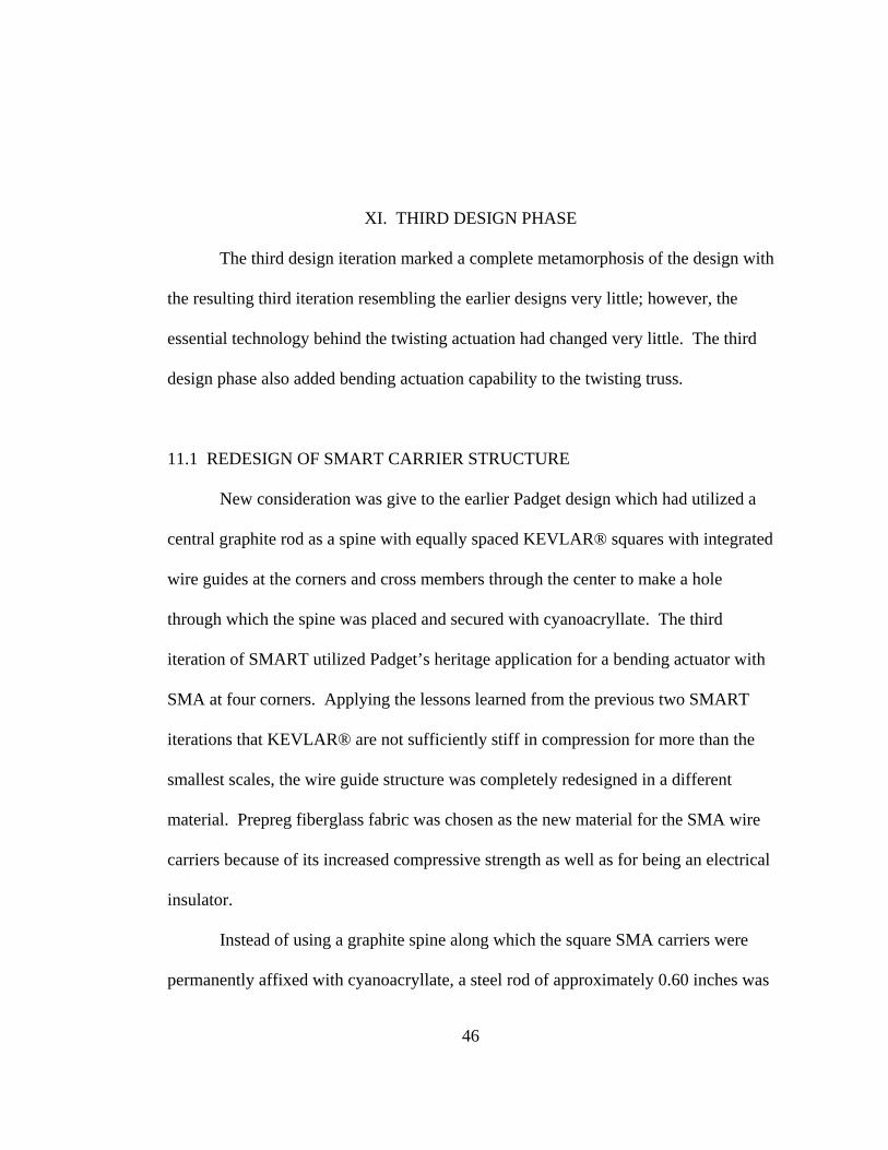
Figure 11.5.1 Collets against the Fiberglass Vertebrae ...................................... 51
Figure 11.6.1 Photograph of the Tool-Hardened Steel Stub and Brass Tubing . 51
Figure 11.6.2 Photograph of the Finished End Cap Assembly .......................... 52
Figure 11.6.3 Photograph of End Cap Mating with End of Central Spine ......... 53
Figure 11.7.1 Photograph of SMA Loop with Washers for Anchoring ............. 54
Figure 11.7.2 Photograph of SMA Loop and Washers Tightened ..................... 54
Figure 11.7.3 Anchor Screw with SMA Assembly Attached ............................ 55
xvii
Figure 11.7.4 Completed Anchor Screw Assembly ........................................... 56
Figure 11.8.1 Base Assembly Before Ready for Tensioning Screws ................. 57
Figure 11.8.2 Finished Base Assembly with Tensioning Screws ...................... 58
Figure 11.10.1 SMA Wires on the Twisting Model of the SMART .................. 60
Figure 12.1.1 Ground Based Test Setup of Bending Truss ................................ 62
Figure 13.1.1 Photograph of SMART at Maximum Bending Deflection With and Without Displacement Measurements on Image .......... 65
Figure 13.1.2 Side-by-Side Comparisons of Bending SMART Pretest, Posttest, and Posttest with Residual Bend Measurement ............. 66
Figure 13.2.1 Photograph of Twisting Truss At Maximum Deflection Posttest ........................................................................ 67
Figure 13.2.2 Plot of Twisting of SMART per Segment ................................... 67
Figure B.1 Photograph of Test Setup Showing Laser, Test Stand, and DC Power Supply ................................................... 75
Figure B.2 Enhanced photograph of the SMA Truss on the Test Stand ............ 75
Figure B.3 Close-up Photograph of the Torsional Strain Relief Device ............ 76
Figure B.4 Photograph of Test Setup with Test Stand, Laser, and Wall Graph Board ............................................................................. 76
Figure C.1. Frame of Maximum Twist Extracted from Video of Twist in Clockwise Direction ...................................................... 78
Figure C.2 Frame of Truss Post Clockwise Twist with Relaxed SMA Extracted from Video of Twist in Clockwise Direction ................... 78
Figure C.3. Frame of Truss at Beginning of Counterclockwise Test Video ...... 79
Figure C.4. Frame Extracted Near Maximum Restoring Counterclockwise Twist from Test Video ..................................................................... 79
Figure D.1. Final Iteration of Twisting Smart Posttest with Measurements of Twist ................................................................... 81

xviii
Figure D.2 Close-up Photograph of Twisting SMART with Color Coding ....... 82
Figure D.3 Researcher Lori Prothero with the Posttest SMART ....................... 82
Figure E.1. Auburn University “Vomit Comet” Team at Team Readiness Review .................................................................. 85
Figure E.2. Ream Readiness Review Presentation with SMART Test Module at Right ......................................................... 85
Figure E.3. Demonstration of SMART Operations Inside Plexiglas Enclosure with NASA C-9 Aircraft in Background ........................ 86
Figure E.4. Unpacking and Presentation of Twisting SMART at Team Readiness Review .................................................................. 86
Figure E.5. Team Preflight Physiological Testing in Altitude Simulator .......... 87
Figure E.6. Andrew Wright during Physiological Test ...................................... 87
Figure E.7. Flight Crew and Flyers from March 9, 2006 at Johnson Space Center in Houston, Texas flight aboard the NASA C-9 Reduced Gravity Aircraft ............................ 88
Figure E.8. Ryan SMART Flyers Leureck and Vanessa Smith from March 9, 2006 Flight .............................................................. 88
Figure E.9. Andrew Wright, Backup Flyer for SMART Received Opportunity to Fly with Experiment from Another University on March 9, 2006 ........................................................... 89
Figure E.10. Ryan Leureck During Reduced Gravity Flight .............................. 89
Figure E.11. Andrew Wright During Reduced Gravity Flight ........................... 90
Figure E.12. Ryan Leureck and Vanessa Smith Operating SMART During Reduced Gravity Parabola .................................. 90
Figure E.13. Vanessa Smith and Ryan Leureck Observing SMART During Reduced Gravity Parabola .................................. 91
Figure E.14. Vanessa Smith and Ryan Leureck Observing SMART Through Top of Plexiglass Enclosure ............................. 91
xix
Figure E.15. Flight Crew and Flyers from March 10, 2006 at Johnson Space Center in Houston, Texas flight aboard the NASA C-9 Reduced Gravity Aircraft .......................... 92
Figure E.16. Smart Flyers Michael Brennison and Meghan Brown with SMART Test Module on March 10, 2006 Flight ................... 92
Figure E.17. Smart Flyers Michael Brennison and Meghan Brown During Reduced Gravity Flight on March 10, 2006 ....................... 93
Figure E.18. Meghan Brown During Reduced Gravity ...................................... 93
Figure E.19. Michael Brennison Checking Computer In Flight ........................ 94
Figure E.20. Meghan Brown Checking SMART Bending Truss Experiment ... 94

1
I. INTRODUCTION
Shape memory alloys (SMAs) are a special class of metals with a unique
crystalline structure which can be heat trained to remember a specific size and shape
to which it returns when a heat stimulus is applied. The unique characteristics of
shape memory alloys (SMAs) were first discovered in the 1930s by Arne Örlander
while he was working with Cadmium-gold alloys.1 In 1962, William Buehler and
other researchers at the Naval Ordnance Laboratory (NOL) discovered the memory
effects in nickel-titanium alloy, which Buehler had previously renamed NiTiNOL in
1956 to include the Naval Ordnance Laboratory acronym.2 Buehler discovered the
ability of SMA to recover from high strains, of approximately 8% without plastic
deformation.2 Eight percent strain recovery means SMA can stretch as much as 8% of
the original length and return to its original length without any permanent deformation
or change in the strength of the SMA. Because of the ability to stretch and shrink
repeatedly with strain recovery, SMA is the ideal material for mechanical devices
which perform repetitive tasks.
There are three general categories of SMA devices: devices which use the
SMA shape recovery directly, stress recovery devices which exploit the stress of SMA
when it is constrained, and actuators which use the force induced by SMA to cause
movements in other objects.3

2
An actuator, as the name implies, is a mechanical device which causes
something else to move.4 Actuators typically contain a large number of working parts
such as gears and hydraulic pistons. SMA actuators reduce the complexity of
conventional actuators by replacing the numerous mechanical parts with a single wire
capable of the same actuation force.5 Replacing hydraulic pistons and gears with a
single wire also reduces the vibrational settling time, or shaking, as the actuator
moves. Long vibrational settling times cause hydraulically mechanized machines to be
more clumsy and imprecise in their movements.4 As a result, vibration is a major
limiting factor in robotic design which is highly dependent on precise actuators
designed for specific desired movements.
There are already some SMA actuators for simple bending; however, only one
of these designs by Padgett involves bending of an entire truss in two planes.5
Howard, in his thesis on his design of a rotary SMA actuator, remarked that there exist
very few designs for rotary actuators.6 Howard’s design is the only rotary design
found of record which had more than one degree of freedom; however, both of its
degrees of freedom are rotational and in a traditional joint-type actuator.6 Drawing
from the success of a bending-truss actuator by Padgett and the need for rotary
actuators, the Shape Memory Alloy Robotic Truss was conceived as a two-degree-of-
freedom bending actuator with a third rotary degree of freedom in the form of axial
twisting of the truss for a total of three degrees of freedom.
Because the design of SMART was so complex, the final design was
accomplished in a number of iterative stages with smaller, more specific goals. The
first goal of this research project was to develop an axially twisting truss actuator as no

3
such device existed previously. The original hypothesis was that helically wound
SMA wires around the truss when heated, would cause the entire truss to twist. After
many design and prototyping iterations, a fully functional prototype twisting truss
actuator was produced and tested. The twisting truss actuator will be discussed in
further detail later in this thesis. After a twisting actuator had been developed, the
second goal was to develop a bi-directional twisting actuator by incorporating
opposing SMA actuator wires in a slightly modified truss. The Bi-directional
requirement meant that the truss had to be untwisting mechanically rather than untwist
due to cooling wire relaxation and gravity. After this second phase was accomplished,
the truss had to be completely redesigned to accommodate bending. Even though the
third generation truss design radically differed from the first two designs, the method
by which the truss actuated was still the same as the first and second generations with
the added bending capability similar to Padgett’s actuator.
The third generation truss reverted to a configuration first proposed by Padgett
for his bending truss actuator which had a common central spine. Along this spine
were linearly spaced square trusses to which SMA attached linearly from truss to truss
at each of the four corners; however, that is where the similarities between the Padgett
design and SMART end. There are many key differences between the second and
third generation designs as well as between the third generation bending and twisting
actuator and Padgett’s design.
In the third design generation, two actuators were incorporated into the same
truss structure: one was a twisting actuator and the other was a bending actuator. By
using the same truss for separate mode actuators, it was proposed that the truss could

4
be actuated as an integrated actuator of twisting and bending. This was also supported
by a test in the first phase of design in which a linear set of SMA wires was connected
at the same time while the twisting mode SMA wires were activated and did not have
any affect on the actuation. In the third phase of design, small sliding insulators were
added to the SMA wires in areas where the wires might have come into contact as a
result of actuation of the bi-directional twisting. The effective use of insulators proved
that SMA wires in bending could also be isolated from twisting-mode SMA wires
through insulators as well. The fourth phase of the SMART project was extensive
ground-based testing of both bending and twisting actuating trusses. The fifth phase
was the reduced gravity test of the SMART bending mode and twisting mode aboard
the NASA C-9 reduced gravity aircraft. The testing aboard the C-9 aircraft in
parabolic freefall certified SMART and its structural components for reduced gravity
operation such as found in space.
Further research is needed to develop a truly-integrated bending and twisting
truss actuator as well as an actuator suitable for operation in a space environment.
5
II. SHAPE MEMORY ALLOY
Although Shape Memory Alloys were discovered much earlier by Arne
Orlander, they have only been used in engineering applications since the discovery of
NiTiNOL, nickel-titanium alloy, in the 1950's.2 William Buehler discovered the shape
memory and high strain characteristics of NiTiNOL SMA quite by accident. In 1959,
Buehler and an assistant made six NiTiNOL bars in an arc-melting furnace. Buehler
dropped the first cooled bar on the concrete floor to see what the bar would do. The
bar made a thud indicative of some kind of vibrational damping within the material
itself. Buehler tested the other bars which were still warm and found the warm bars
resonated with a “bell-like quality sound.” Buehler then cooled the warm bars in a
nearby water fountain to see if the resonance of the warm bars was temperature
dependent. He found that the bars made the same thud sound as the cooled bar did.
To test the reverse characteristic, he warmed the bars in boiling water, and the bars
regained their resonance.
Buehler continued to test the bars warm and cold and found the trend remained
the same; the warm bars were resonant and the cold bars were damped. Buehler
understood that the change in the acoustic damping indicated that the atomic structure
must change as a result of the temperature change. The significance of the change in

6
atomic structure at different temperatures was not significant until the shape memory
effects of NiTiNOL were discovered.
Raymond Wiley joined the Naval Ordnance Laboratory (NOL) in 1960 and
worked on failure analysis of different metals including NiTiNOL. In a briefing,
Wiley demonstrated the fatigue resistance by repeatedly bending a NiTiNOL wire
which had a diameter of one hundredth of an inch. Repeated bending typically
weakens metals until they eventually break; however the NiTiNOL wire did not break.
While passing the wire around the boardroom table so that everyone could have a turn
bending the metal, David Muzzey, one of the technical directors of the NOL, “decided
to see how it would behave under heat.” Muzzey held the accordion folded NiTiNOL
strip in the flame of his pipe lighter and the wire became instantly straight by itself.
Buehler, hearing about the incident, decided the shape recovery phenomenon was
related to the earlier observation about sonic damping and resonance; however, the
shape memory effects would be more useful. Buehler’s earlier observation that the
structure of the NiTiNOL’s atoms changed was later shown to be a change between
two distinct crystalline structures depending on temperature.
2.1 CRYSTALLINE STRUCTURE
Shape memory alloys have two distinct phases called Austenite, which is the
hot phase, and Martensite, which is the cold phase.2 The Austenitic phase is known
for its regular lattice pattern as shown in the following figure.7
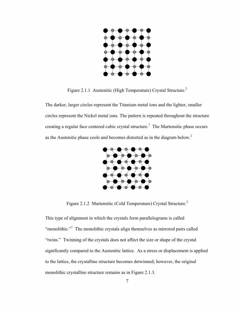
Figure 2.1.1 Austenitic (High Temperature) Crystal Structure.2
The darker, larger circles represent the Titanium metal ions and the lighter, smaller
circles represent the Nickel metal ions. The pattern is repeated throughout the structure
creating a regular face centered cubic crystal structure.7 The Martensitic phase occurs
as the Austenitic phase cools and becomes distorted as in the diagram below.2
Figure 2.1.2 Martensitic (Cold Temperature) Crystal Structure.2
This type of alignment in which the crystals form parallelograms is called
“monolithic.”7 The monolithic crystals align themselves as mirrored pairs called
“twins.” Twinning of the crystals does not affect the size or shape of the crystal
significantly compared to the Austenitic lattice. As a stress or displacement is applied
to the lattice, the crystalline structure becomes detwinned; however, the original
monolithic crystalline structure remains as in Figure 2.1.3.
7

Figure 2.1.3 Deformed Martensitic (Cold Temperature) Crystal Structure.2
The structure shown in Figure 2.1.3, which is still in the Martensitic phase, has been
deformed.2 At this point heat can be applied and the lattice realigns in the Austenite
form. The diagram below shows the crystalline transformations as the structure heats
and cools.
AUSTENITE
MARTENSITE(TWINNED)
MARTENSITE(DEFORMED)
COOLING HEAT RECOVERY
DEFORMING
δ
Figure 2.1.4 Diagram of Crystalline Transformations as SMA Heats and Cools, δ Denotes Elongation.2
8
2.2 TEMPERATURE EFFECTS ON SHAPE MEMORY
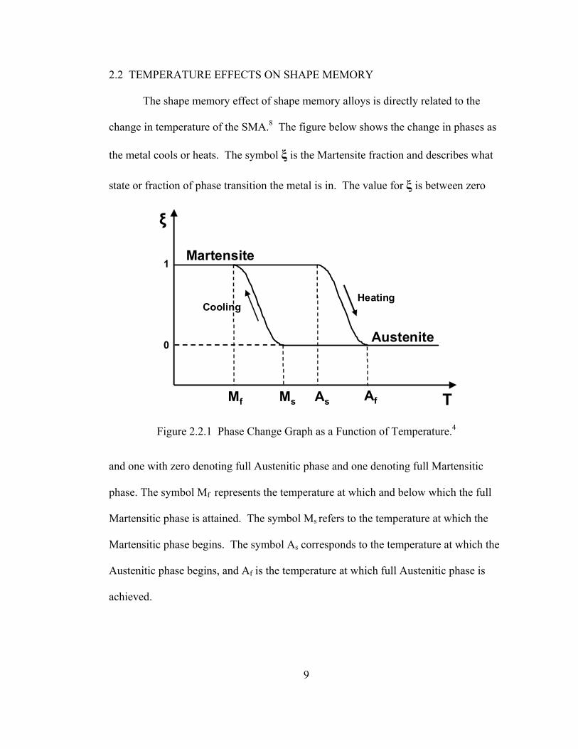
The shape memory effect of shape memory alloys is directly related to the
change in temperature of the SMA.8 The figure below shows the change in phases as
the metal cools or heats. The symbol ξ is the Martensite fraction and describes what
state or fraction of phase transition the metal is in. The value for ξ is between zero
0
1
ξ
TMf AfMs As
Martensite
Austenite
HeatingCooling
Figure 2.2.1 Phase Change Graph as a Function of Temperature.4
and one with zero denoting full Austenitic phase and one denoting full Martensitic
phase. The symbol Mf represents the temperature at which and below which the full
Martensitic phase is attained. The symbol Ms refers to the temperature at which the
Martensitic phase begins. The symbol As corresponds to the temperature at which the
Austenitic phase begins, and Af is the temperature at which full Austenitic phase is
achieved.
9

2.3 PHYSICAL SIGNIFICANCE
Recall in the Austenitic phase, the crystals align and remember a specific
shape. As the material loses heat, it changes phases to the Martensitic phase which
retains the same shape since twinning does not change the exterior shape significantly.
As more heat is lost, the Shape Memory Alloy (SMA) becomes fully Martensitic, and
it is possible to physically realign the crystals of the SMA. As the material is heated,
it returns to the regular alignment of the Austenitic lattice without any trace of the
Martensitic deformed shape.
10
Figure 2.3.1 Diagram of Shape Memory Alloy Changing Physical Shape and Phases.2
HEAT
HEAT COOL
T = Af T = Mf T = Mf T = Af
T = Mf
Austenitic, Initial State Martensitic, Undeformed Martensitic, Mechanically Deformed
Austenitic, Shape Recovered
Martensitic, Undeformed
COOL
The physical significance of the phase change can be seen in Figure 2.3.1.
The warm Austenitic phase metal retains its shape as it cools to the Martensitic phase.
In the Martensitic phase, the metal is deformed mechanically. As heat is applied, the
metal returns to its original size and shape without any remaining deformation.

2.4 FLEXINOL®
FLEXINOL® is the proprietary NiTiNOL alloy manufactured by Dynalloy,
Incorporated and the particular NiTiNOL SMA wires used in SMART. 9 Dynalloy
withholds the exact composition of FLEXINOL® as well as their processing and
tempering of the alloy as trade secrets; however, they do supply extensive technical
data specific to FLEXINOL® on their company website, www.dynalloy.com.
According to the company website, this alloy was specifically engineered to be used in
actuators; therefore, the company supplies the maximum pull force of a FLEXINOL®
wire given its diameter. It is also assumed that in the typical application, the SMA
wires will be heated by electrical resistance in a circuit. Dynalloy supplies the
resistance of the wires in ohms per inch length as well as the current required in
milliamps given the diameter of the wire in Table 2.4.9
Table 2.4 NiTiNOL Flexinol® Published Technical Data9
FLEXINOL© Technical Data
Diameter Size
(Inches)
Resistance (Ohms per
Inch)
Maximum Pull Force (grams)
Current at Room
Temperature (mA)
ContractionTime
(seconds)
Off Time 70° C Wire (seconds)
Off Time 90° C Wire (seconds)
0.001 45 7 20 1 0.1 0.06 0.0015 21 17 30 1 0.25 0.09 0.002 12 35 50 1 0.3 0.1 0.003 5 80 100 1 0.5 0.2 0.004 3 150 180 1 0.8 0.4 0.005 1.8 230 250 1 1.6 0.9 0.006 1.3 330 400 1 2 1.2 0.008 0.8 590 610 1 3.5 2.2 0.01 0.5 930 1000 1 5.5 3.5 0.012 0.33 1250 1750 1 8 6 0.015 0.2 2000 2750 1 13 10 0.02 0.12 3562 4000 1 18 15
11

12
Using the resistance and current, it is easy to calculate the voltage across the
wires given the circuit configuration. In a simple, one strand circuit with power
supply connected directly to the wire, the voltage obeys Ohm's Law as presented in
equation (1) with voltage, V, current, I, and resistance, R.
V = I × R (1)
According to the supplied technical data as well as sample testing in the
laboratory, FLEXINOL® has been shown to have very good fatigue qualities with the
laboratory tested capability of over a hundred-thousand flex and relax cycles without
breakdown.4 FLEXINOL® is available in a range of gauges from 0.001 inch diameter
to 0.02 inch diameter wires and has two different choices of transition temperatures:
70°C and 90°C. 9 The initial smaller scale prototype SMART used 0.001 inch
diameter SMA wires; however, the final prototypes which were almost ten times
larger in size than the original SMART switched to 0.005 inch diameter SMA wires
since there was heavier structure to actuate in the later designs.
The contraction time is approximately one second for each of the wires with
the relaxation time varying between 0.1 seconds to a few seconds due to the diameter
and the transition temperature of the chosen wire.9 The relaxation time varies because
cooling is convective with ambient air and varies with surface area and thus with the
diameter of the wire.4 Crystalline differences in the transition temperature also cause
the cooling times to be inherently different.4 The technical data assumes that the
wires are at room temperature and are isolated from radical air currents.9
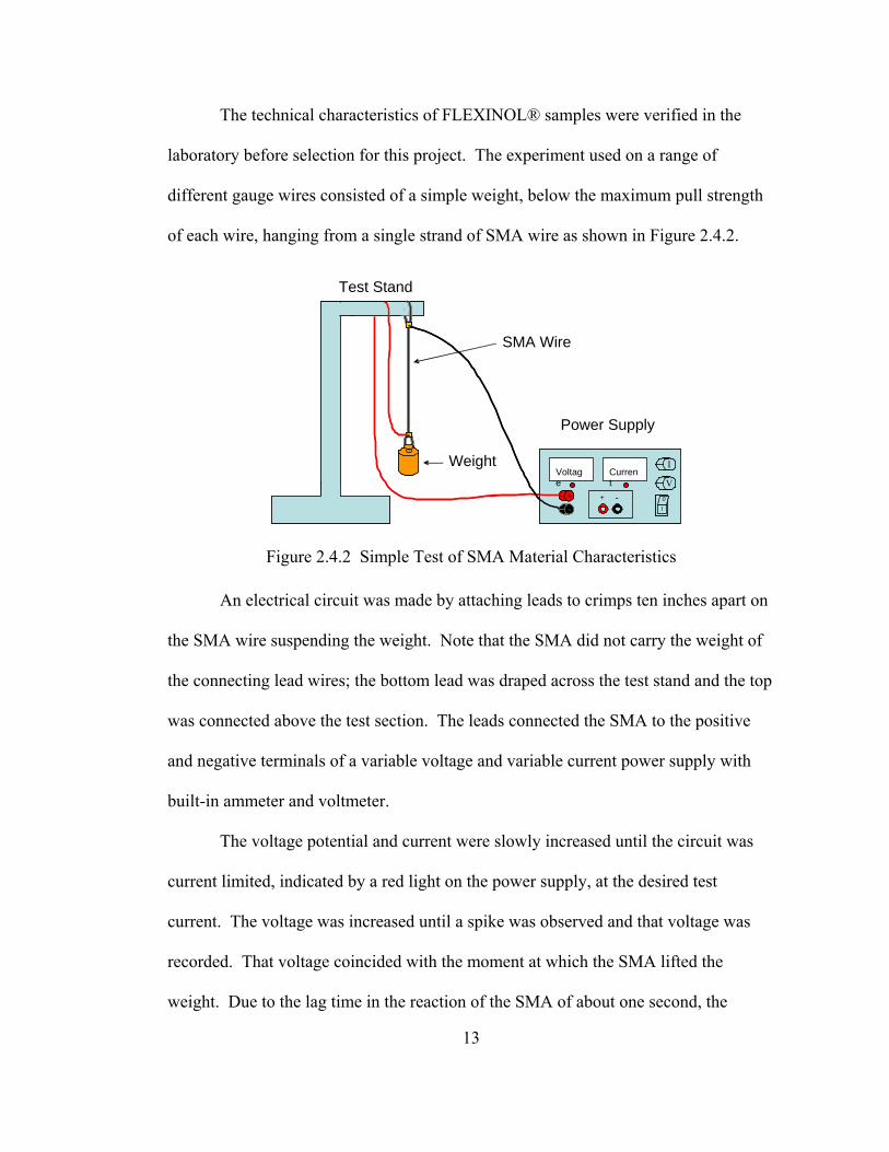
The technical characteristics of FLEXINOL® samples were verified in the
laboratory before selection for this project. The experiment used on a range of
different gauge wires consisted of a simple weight, below the maximum pull strength
of each wire, hanging from a single strand of SMA wire as shown in Figure 2.4.2.
13
Figure 2.4.2 Simple Test of SMA Material Characteristics
An electrical circuit was made by attaching leads to crimps ten inches apart on
the SMA wire suspending the weight. Note that the SMA did not carry the weight of
the connecting lead wires; the bottom lead was draped across the test stand and the top
was connected above the test section. The leads connected the SMA to the positive
and negative terminals of a variable voltage and variable current power supply with
built-in ammeter and voltmeter.
The voltage potential and current were slowly increased until the circuit was
current limited, indicated by a red light on the power supply, at the desired test
current. The voltage was increased until a spike was observed and that voltage was
recorded. That voltage coincided with the moment at which the SMA lifted the
weight. Due to the lag time in the reaction of the SMA of about one second, the
+ +
--
I V
Voltage
Current
I0 + +
--
I V
Voltage
Current
I
0
SMA Wire
Test Stand
Weight
Power Supply
voltages were read directly from the power supply just as the ammeter registered the
voltage spike instead of using only the visual observation of the wire contracting. The
test was repeated with other incremental currents tested and corresponding voltages
recorded until the maximum current was exceeded and failure of the SMA occurred
due to overheating.
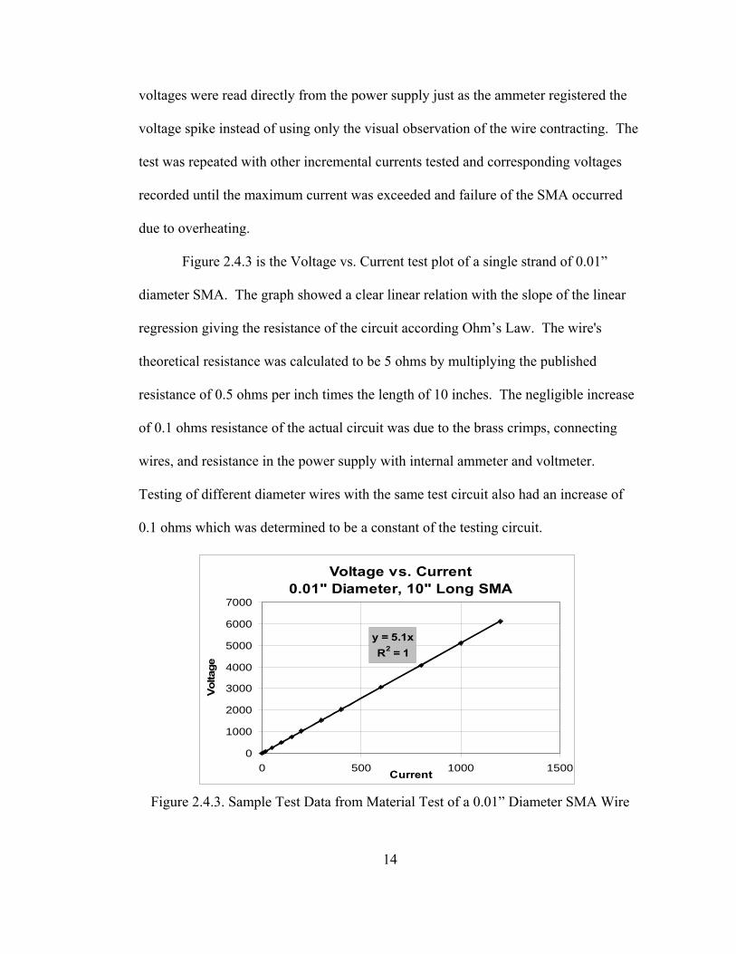
Figure 2.4.3 is the Voltage vs. Current test plot of a single strand of 0.01”
diameter SMA. The graph showed a clear linear relation with the slope of the linear
regression giving the resistance of the circuit according Ohm’s Law. The wire's
theoretical resistance was calculated to be 5 ohms by multiplying the published
resistance of 0.5 ohms per inch times the length of 10 inches. The negligible increase
of 0.1 ohms resistance of the actual circuit was due to the brass crimps, connecting
wires, and resistance in the power supply with internal ammeter and voltmeter.
Testing of different diameter wires with the same test circuit also had an increase of
0.1 ohms which was determined to be a constant of the testing circuit.
Voltage vs. Current
0.01" Diameter, 10" Long SMA
y = 5.1xR2 = 1
0
1000
2000
3000
4000
5000
6000
7000
0 500 1000 1500Current
Volta
ge
Figure 2.4.3. Sample Test Data from Material Test of a 0.01” Diameter SMA Wire
14

15
III. INITIAL DESIGN PHASE
The first challenge was to establish the initial and derived requirements of the
design. To create a twisting only actuator, the truss had to be structurally flexible in
torsion while stiff in tension and compression. The truss also had to accommodate
connections and wire guides for the SMA to transfer force from the SMA as torque on
the truss. The SMA wires, which were heated by electricity, had to be attached in
such a way that the wires would not touch each other or anything that would conduct
electricity.
3.1 STRUCTURAL DESIGN
The first requirement that the truss has to be flexible in torsion and stiff in
tension and compression imposed that the truss be fixed in five of the six degrees of
freedom: translation in the x-, y-, and z-direction and rotation about the x-, y-axis,
while still being able to rotate easily about the z-axis as shown in Figure 3.1.1.
Triangular trusses were used to constrain the xy-plane of the truss, which
constrained translations in the x- and y-directions. Stiff horizontal beam members
connect the vertex of one triangular truss to the corresponding vertex of another as in
Figure 3.1.1. The arrangement of the three horizontal beams with a triangular base
effectively constrained bending in the xz- and yz- planes as well as any linear
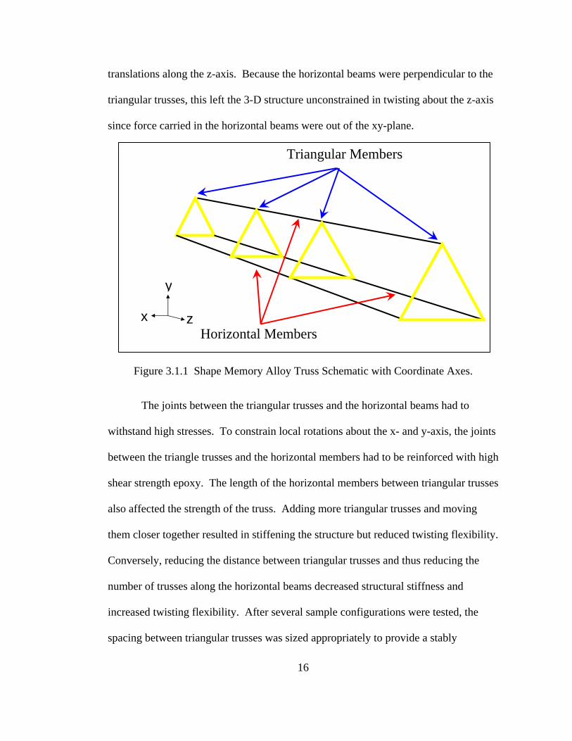
translations along the z-axis. Because the horizontal beams were perpendicular to the
triangular trusses, this left the 3-D structure unconstrained in twisting about the z-axis
since force carried in the horizontal beams were out of the xy-plane.
Triangular Members
Horizontal Members
y
z x
Figure 3.1.1 Shape Memory Alloy Truss Schematic with Coordinate Axes.
The joints between the triangular trusses and the horizontal beams had to
withstand high stresses. To constrain local rotations about the x- and y-axis, the joints
between the triangle trusses and the horizontal members had to be reinforced with high
shear strength epoxy. The length of the horizontal members between triangular trusses
also affected the strength of the truss. Adding more triangular trusses and moving
them closer together resulted in stiffening the structure but reduced twisting flexibility.
Conversely, reducing the distance between triangular trusses and thus reducing the
number of trusses along the horizontal beams decreased structural stiffness and
increased twisting flexibility. After several sample configurations were tested, the
spacing between triangular trusses was sized appropriately to provide a stably
16

17
stiffened structure which retained the a maximum amount of flexibility. The
triangular trusses which measure one inch on each side, were spaced every two inches
along the horizontal beams.
3.2 MATERIAL SELECTION
Materials were carefully chosen for the truss members. Boron filaments
which were 0.050 inch diameter were selected for the horizontal members because of
their high compressive strength. Boron has a Young’s modulus of elasticity of 478
GPa.10 Compared to the Young’s modulus of elasticity of steel, which is 200 GPa,11
boron is more than twice as stiff as steel.
Strands of prepreg KEVLAR® which measured 0.04 inches by 0.012 inches
were selected to make the triangular truss members. KEVLAR® possesses very good
tensile stiffness and strength properties while being poorer in compression. Due to
twisting actuation of the truss, the KEVLAR® trusses were only subjected to high
tension loads such that given the scale of the application, the local stiffness of the resin
in the KEVLAR® truss was sufficient for the nominal compressive loads. The
modulus of elasticity of KEVLAR® is 60 – 120 GPa and the tensile strength is 3 GPa,
or 3000 MPa.12
Incorporating the SMA actuation into the truss posed some difficulty. To
actuate the truss, the SMA needed to be attached to the truss to transfer the pull force
evenly at each node. The main obstacle was that SMA is difficult to bond with any
material, including with itself, because the elasticity and strain recovery that make the
material so useful, also prevents gluing, soldering, compression fitting, etc.

18
Many methods were tested before discovering that the most effective method for
constraining SMA is to knot it with itself inside of a crimp. The friction of the knot
and crimp was sufficient to hold the SMA since the force required to pull the SMA out
of it is usually more than the maximum load rated for the wire. It was simply not
practical to replicate the complicated knot/crimp joint while ensuring even pre-
tensioning between each crimped section of SMA at each of the three nodes of all the
triangular trusses. As a result, wire guides were incorporated into the KEVLAR®
trusses through with the SMA could transfer the load as a contact load. The SMA
wires at each end of the truss were knotted and crimped with a crimp larger that the
diameter of the wire guide so that it could not be pulled through the hole.
Another concurrent complication in the design was that the SMA wires had to
be electrically insulated from each other as well as from the boron filaments which are
conductors. Incorporating the wire guides into the triangular trusses was the logical
solution since KEVLAR® is an electrical insulator. SMA wire guides with a diameter
of 0.01 inch were added at each node of the KEVLAR® triangle design with a
geometric arrangement which prevented the SMA wires from touching each other or
the boron.
3.3 KEVLAR® TRUSS MANUFACTURING
A single strand of KEVLAR® prepreg was tied in a pattern of knots, molded
around piano wires larger than the diameter of the horizontal members, and pressed
between two metal caul plates to create a triangular truss with holes large enough to
accept the boron filaments at each vertex as well as the SMA as shown in Figure 3.3.1.

Figure 3.3.1 Schematic of a KEVLAR® Truss Lay-Up
Whole stacks of molded KEVLAR® using the top caul-plate surface as the
bottom surface for the next mold were stacked together and clamped. This method of
efficient manufacturing was developed by Padget; however, adding knots and weaving
the strands for added strength and adhesion of the epoxy was unique to this particular
application. The whole stack was placed in an autoclave to cure the impregnated resin
in the KEVLAR® strand. The KEVLAR® triangles were heated in the autoclave for
eight hours at 170°C using standard composite materials manufacturing techniques.
The result of the process can be seen in Figure 3.3.2 and Figure 3.3.3 which depict the
regular pattern of the finished KEVLAR® triangular truss. The wire guides were
positioned symmetrically at each vertex of the triangular truss. Figure 3.3.2 shows the
indexing system of holes in the triangular truss sections.
19

20
Boron Filament Interface Guides for
SMA Wires
Figure 3.3.2 Enlargement of a Triangular Truss Section to Show the Boron Filament Interface and Guides for the SMA Wires.
2B
B
R
R
S
S
L
L
1S
B
R
3
L
Figure 3.3.3 Triangular Truss Shown With Hole Indexing System. B Denotes the Boron Interface, L Denotes Local Left Upper Hole, R Denotes Local
Right Upper Hole, S Denotes Shared Hole, and 1,2, and 3 Denote the Vertex.

21
3.4 SMA WINDINGS
Three SMA wires were wound helically around the boron-KEVLAR® truss. It
is important to note that the strands were parallel so they never touched. The
following is a detailed description of the SMA windings using the indexing system.
The first SMA wire started at vertex 1 in the hole L of truss one. Then the
same SMA wire passed through the second truss at hole S of vertex 2. Then that SMA
wire passed through hole L at vertex 3 of the third truss and so on down the length of
the truss. Two other SMA wires started separately at vertex 2 and vertex 3 of truss 1
and continued in a pattern similar to that of the first wire. None of the wires crossed
each other or came into contact with the boron. Three opposing SMA wires were
similarly strung starting at the other end of the truss. The wires ran through the shared
and right holes of the KEVLAR® triangles. The end result was that three SMA wires
ran in a clockwise direction three wires ran in a counterclockwise direction without
any of the wires crossing.
Opposing pulling wires heated alternately act much like bicep and tricep
muscles do to actuate and restore position of an elbow joint. As one muscle (or SMA
wire) contracts, the opposing muscle (or SMA wire) extends and vice versa for motion
in the opposite direction. For the laboratory test, however, only twisting in only the
clockwise direction was tested to prove the basic concept of SMA torsional actuation.
The counterclockwise winding would work in an identical manner for actuation in the
opposite direction; therefore, testing of the counterclockwise windings was redundant.
The redundant wires were left in the truss to show that the opposing wires do not come
in contact with the other set of SMA wires.

22
IV. INITIAL DESIGN PHASE TESTING
A truss constructed of four triangular KEVLAR® trusses secured with
cyanoacryllate at two inch intervals on three boron filaments as previously described
was placed on a test stand. Small sections of brass tubing were crimped at each end of
pre-stretched SMA wires to provide a surface to pull against the end of the truss and
transfer the force to the truss. Contact wires which had a 0.15 inch diameter were then
soldered to the brass crimps. A simple electrical circuit was made with a variable DC
power supply, external ammeter used to accurately measure the current, internal
voltmeter used to accurately measure the voltage, and SMA wires, which acted as
three resistors in parallel. The electrical resistance in the SMA wires provided the heat
to the SMA. The electrical supply/control system is shown in Figure 4.1.1.
The truss was attached to the test stand with tape around the top contact wires
as in Figure 4.1.2. The straight contact wires naturally resist torsion and would have
restrained the actuation of the SMA Truss. Therefore, the contact wires at the bottom
of the truss were connected to a torsional strain relief device. The torsional strain
relief device was simply a length of the same type of wire used as contact wires which
had been coiled into a 0.4 inch diameter. The coiled shape allowed the SMA Truss to
deflect more easily.

Figure 4.1.1 Photograph of Voltmeter, Ammeter, and DC Power Supply.
Figure 4.1.2 SMA Truss on Test Stand with Torsional Relief Coil at Bottom
23

A laser mirror was mounted just above the torsional strain relief. A laser was
focused onto the mirror and the reflection from the mirror onto a graph board to
measure the deflection as in Figure 4.1.3.
LASER
Test Stand
Graph Board
Figure 4.1.3 Diagram of SMA Truss on Test Stand with Laser, Mirror,
and Graph Board Measuring Setup.
The focal lengths of the laser and graph board were set such that one inch
deflection on the graph board corresponded to one degree of deflection of the truss.
The geometry of the reflected laser beam from the deflection mirror is shown in
Figure 4.1.4.
24

Opaque Wall
Flat Mirror
LaserTheoretical Origin ofIncident Ray
Reflected Ray
Normal Lineθr
θi
Fixed Distance
Opaque Wall
Flat Mirror
LaserTheoretical Origin ofIncident Ray
Reflected Ray
Normal Lineθr
θi
Fixed Distance
Figure 4.1.4 Diagram of Basic Geometry of Laser Reflection In Figure 4.1.4, an opaque wall was positioned behind the laser source at a
fixed distance parallel to a flat mirror. The symbol θi represents the angle of incidence
between the source laser beam and the normal line to the mirror. The angle of
reflection θr is the angle between the normal line to the mirror and the reflected laser
beam from the mirror. The angle of incidence and the angle of reflection are equal
according to the Law of Reflection presented in Equation (2).
θθθ ≡≡ ir (2)
Figure 4.1.5 depicts the same setup as the flat mirror deflects an angle δ.
The perceived angle of deflection on the opaque wall is α.
25

Opaque Wall
Flat Mirror
LaserTheoretical Origin ofIncident Ray
Original Reflected Ray
Original Normal Line
Fixed Distance
δ
αNew Normal Line
New Reflected Ray
δ
Opaque Wall
Flat Mirror
LaserTheoretical Origin ofIncident Ray
Original Reflected Ray
Original Normal Line
Fixed Distance
δ
αNew Normal Line
New Reflected Ray
δ
Figure 4.1.5 Diagram of the Geometry Depicting Angular
Deflection of the Beam and Mirror
Since the position of the origin beam stayed fixed relative to the wall, the
perceived angle change α is really the sum of the change in angle of the incident beam
and of the reflected beam from the previous mirror position when the mirror was
parallel to the wall.
ri θθα Δ+Δ= (3)
Defining the change in angle as the difference between the new angle and old
angle and using the identity from Equation (2) results in Equation (4):
0θθθ −=Δ (4)
Equation (3) then becomes:
θα Δ= 2 (5)
Recalling that the mirror deflection is δ and geometric relations for
perpendicular lines, the deflection of the normal line is also δ. The angle δ is also the
26

true angle of deflection and the change in deflection of the angle of incidence and
angle of reflection. Therefore, Equation (5) can be rewritten in terms of δ.
δα 2= (6)
Since linear distances are more easily measured than angles, angle α is
calculated geometrically from the linear displacement of the reflected beam on the
opaque wall. Using a fixed distance between the opaque wall and the mirror which is
many orders of magnitude larger than the linear displacement, the wall may be
assumed to be approximately perpendicular to the original reflected beam. Then the
calculation of α becomes simple trigonometry as depicted in Figure 4.1.6.
Figure 4.1.6 Depiction of the Perceived Angle Change α with Wall Assumption
Opaque Wall
New Reflected Ray
Flat Mirror
y
α
x
Original Reflected Ray
The definition for the tangent function of an angle in a right triangle is used to
determine angle α. The equation for α is:
yxTan =)(α (7)
Solving the equation for y, the previous equation becomes:
)(αTanxy = (8)
27

Realizing that for calculation purposes it would be much easier if δ of 1° corresponds
to x = 1”, we let α = 2˚ recalling from Equation (6) that α is twice δ. Plugging in
Equation (8), we get:
"65.28)1(
"1≈
°=
Tany (9)
Thus, the experiment used a fixed distance between the mirror and the wall of 28.65”
so that an inch of lateral deflection of the laser beam on the wall corresponded to a 1˚
twist of the truss.
A range of voltages was applied to the circuit, and the current as well as the
angular deflection were measured and recorded. The data was afterward compiled
into a table and plotted. More photographs from the test setup may be found in the
Appendix.
28

V. INITIAL DESIGN PHASE DATA
The twisting of the SMA truss can be seen qualitatively below in the
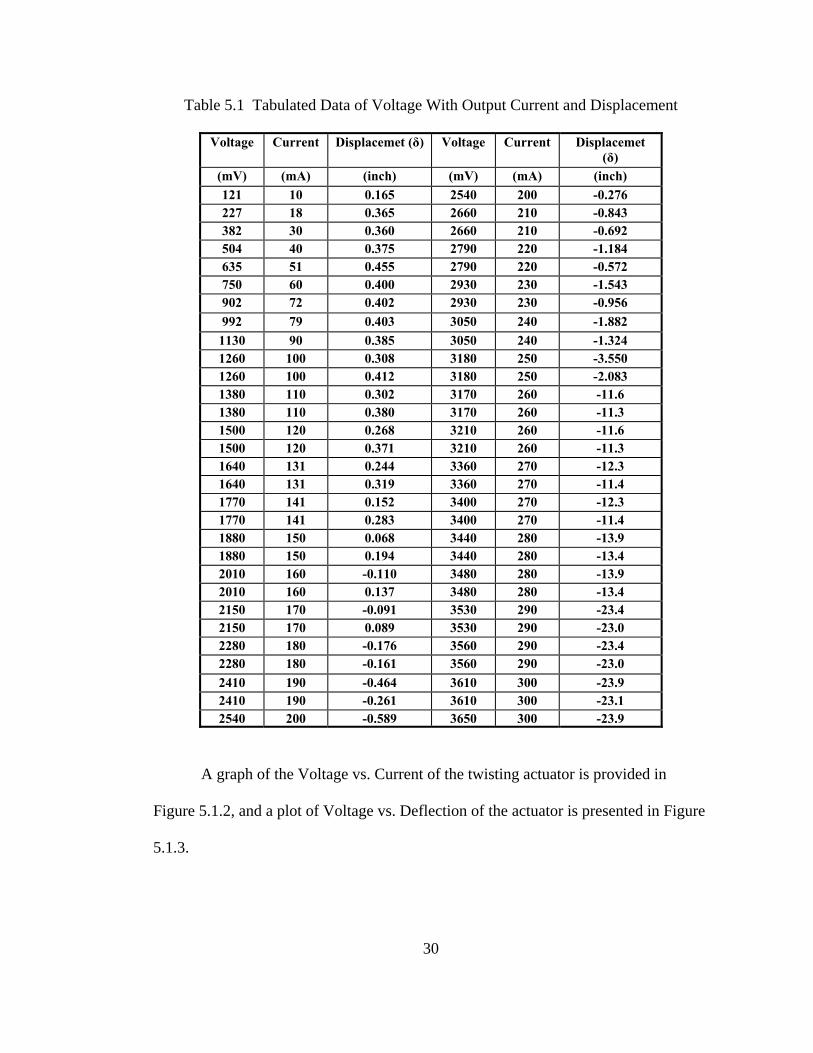
photograph. Also presented is a tabulated chart of the data collected in Table 5.1.
Figure 5.1.1 SMA Truss on Test Stand After Testing.
29
30
Table 5.1 Tabulated Data of Voltage With Output Current and Displacement
Voltage Current Displacemet (δ) Voltage Current Displacemet (δ)
(mV) (mA) (inch) (mV) (mA) (inch) 121 10 0.165 2540 200 -0.276 227 18 0.365 2660 210 -0.843 382 30 0.360 2660 210 -0.692 504 40 0.375 2790 220 -1.184 635 51 0.455 2790 220 -0.572 750 60 0.400 2930 230 -1.543 902 72 0.402 2930 230 -0.956 992 79 0.403 3050 240 -1.882 1130 90 0.385 3050 240 -1.324 1260 100 0.308 3180 250 -3.550 1260 100 0.412 3180 250 -2.083 1380 110 0.302 3170 260 -11.6 1380 110 0.380 3170 260 -11.3 1500 120 0.268 3210 260 -11.6 1500 120 0.371 3210 260 -11.3 1640 131 0.244 3360 270 -12.3 1640 131 0.319 3360 270 -11.4 1770 141 0.152 3400 270 -12.3 1770 141 0.283 3400 270 -11.4 1880 150 0.068 3440 280 -13.9 1880 150 0.194 3440 280 -13.4 2010 160 -0.110 3480 280 -13.9 2010 160 0.137 3480 280 -13.4 2150 170 -0.091 3530 290 -23.4 2150 170 0.089 3530 290 -23.0 2280 180 -0.176 3560 290 -23.4 2280 180 -0.161 3560 290 -23.0 2410 190 -0.464 3610 300 -23.9 2410 190 -0.261 3610 300 -23.1 2540 200 -0.589 3650 300 -23.9
A graph of the Voltage vs. Current of the twisting actuator is provided in
Figure 5.1.2, and a plot of Voltage vs. Deflection of the actuator is presented in Figure
5.1.3.

Figure 5.1.2 Plot of Voltage vs. Current
Voltage vs. Current
0
500
1000
1500
2000
2500
3000
3500
4000
0 50 100 150 200 250 300 350
Current (mA)
Vol
tage
(mV
)
Figure 5.1.3 Plot of Deflection vs. Voltage
Voltage vs. Deflection
-30
-25
-20
-15
-10
-5
0
5
0 50 100 150 200 250 300 350
Voltage (mV)
Defle
ctio
n (d
egre
es)
Deflection vs. Voltage
Voltage (mV)
31

32
VI. INITIAL DESIGN PHASE CONCLUSIONS
The proof of design SMA Truss actuator performed well during testing and
showed that high angular SMA actuation of a truss section is feasible. When heat was
applied to the SMA, the SMA caused the truss to twist as is evident qualitatively in
Figure 5.1.1. The plot of Voltage vs. Current, Figure 5.1.2, shows a linear relationship
between Voltage and Current. Recalling Ohm’s law that voltage is current times
resistance, the slope of that graph represents the resistance of the system. This is
consistent with the published resistance for the type of SMA wire used in this
experiment. The maximum angular deflection was approximately twenty-three
degrees as shown in the graph of Voltage vs. Deflection, Figure 5.1.3.
SMART met the design requirement that the entire truss twist to accommodate
rotational actuation and was an overall success. Since this stage of the design was an
intermediate proof of design feature to a more complex design, further testing and
development of this particular actuator were abandoned to pursue the integrated
actuator. Future recommendations for developing this particular intermediate actuator
as its own functional design would include integrating the opposing SMA wires for bi-
modal twist and untwist. Also, extensive testing should be performed to determine the
fatigue life of the actuator after repeated cycles of twisting. A mathematical model of
the twisting actuation would also need to be developed using numerical analysis

33
methods as the data did not readily converge to any of the 300 closed form solutions
which were attempted by using curve fit software. The technological strides and proof
of concept discoveries made in the initial design phase directly translated into the
success of the final design of the Shape Memory Alloy Robotic Truss.
34
VII. SECOND DESIGN PHASE
The initial design phase of the SMA Truss actuator demonstrated the capability
of a rotationally actuated truss using helically wound SMA actuator wires. The next
set of design requirements required the capability of bi-directional actuation, so a new
actuator was build which could accommodate bi-directional actuation.
7.1 NEW TRUSS STRUCTURE
Since the small scale of the initial design had made construction tedious and
time consuming, the overall scale was increased to facilitate faster prototyping. The
new triangular KEVLAR® trusses had exactly the same thickness and orientation of
wire guides as the initial design; however the distance between vertices of the new
triangles was increased from one inch to two inches and the wire guide hole diameter
was increased to accommodate new horizontal members and new 0.005 inch diameter
SMA actuator wires. The boron filament horizontal members of the initial design
were replaced with 0.05 inch diameter graphite rods due to the limited selection of
boron diameters on hand and the hazard of working with boron filaments which are
prone to shatter into sharp splinters.
A working prototype truss of 14 inches tall with KEVLAR® triangles fixed
with cyanoacryllate at two-inch intervals was constructed and attached firmly to a base
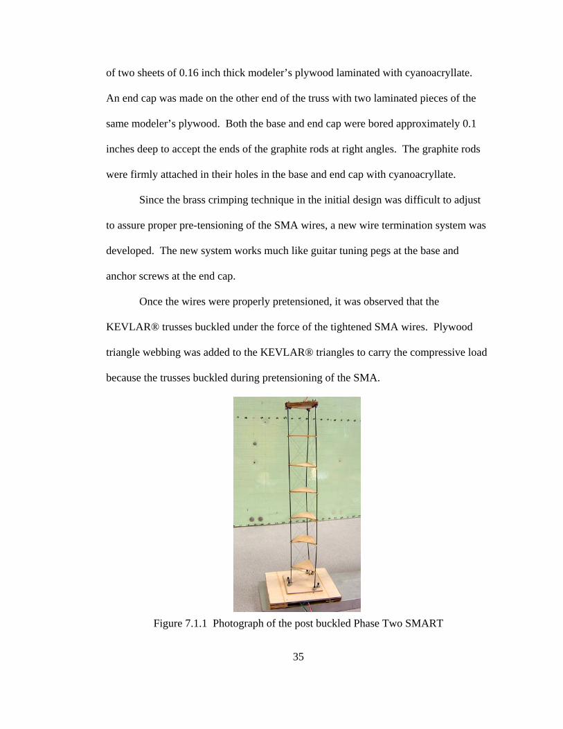
of two sheets of 0.16 inch thick modeler’s plywood laminated with cyanoacryllate.
An end cap was made on the other end of the truss with two laminated pieces of the
same modeler’s plywood. Both the base and end cap were bored approximately 0.1
inches deep to accept the ends of the graphite rods at right angles. The graphite rods
were firmly attached in their holes in the base and end cap with cyanoacryllate.
Since the brass crimping technique in the initial design was difficult to adjust
to assure proper pre-tensioning of the SMA wires, a new wire termination system was
developed. The new system works much like guitar tuning pegs at the base and
anchor screws at the end cap.
Once the wires were properly pretensioned, it was observed that the
KEVLAR® trusses buckled under the force of the tightened SMA wires. Plywood
triangle webbing was added to the KEVLAR® triangles to carry the compressive load
because the trusses buckled during pretensioning of the SMA.
Figure 7.1.1 Photograph of the post buckled Phase Two SMART
35

7.2 END CAP ASSEMBLY
The end cap assembly consisted of a wooden end cap with anchor screws.
Two holes were bored through the end cap at each vertex: one set of holes inside the
triangle made by the graphite rods at the vertices and the other set outside that triangle.
The six holes had a diameter just larger than a 0-80 size screw and were drilled at an
offset angle so they would be accessible to a mini wrench.
The anchor screws were 0-80 size, stainless steel (silver in color), 0.5” long
screws with hex heads and a number of #0 stainless steel washers and 0-80 steel nuts.
The following is a step by step description of an anchor screw assembly:
1. A piece of 0.005 inch diameter SMA wire was threaded straight through a
first size #0 stainless steel washer and a second washer of the same type.
2. The SMA wire was then looped over and threaded in the opposite direction
back through the first washer while skipping over the second washer as
shown in the following photograph.
Figure 7.2.1 Photograph of SMA Loop with Washers for Anchoring
36
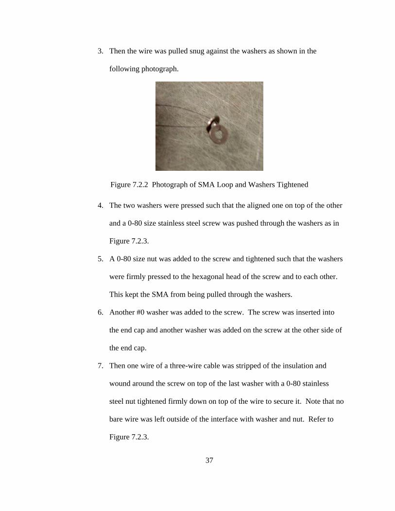
3. Then the wire was pulled snug against the washers as shown in the
following photograph.
Figure 7.2.2 Photograph of SMA Loop and Washers Tightened
4. The two washers were pressed such that the aligned one on top of the other
and a 0-80 size stainless steel screw was pushed through the washers as in
Figure 7.2.3.
5. A 0-80 size nut was added to the screw and tightened such that the washers
were firmly pressed to the hexagonal head of the screw and to each other.
This kept the SMA from being pulled through the washers.
6. Another #0 washer was added to the screw. The screw was inserted into
the end cap and another washer was added on the screw at the other side of
the end cap.
7. Then one wire of a three-wire cable was stripped of the insulation and
wound around the screw on top of the last washer with a 0-80 stainless
steel nut tightened firmly down on top of the wire to secure it. Note that no
bare wire was left outside of the interface with washer and nut. Refer to
Figure 7.2.3.
37

8. Steps 1-7 were repeated for each of the remaining five anchor screws
paying special attention to which wire was attached to which screw
obeying the following: Anchor screws on the inside of the triangle were
attached to one to each wire of a three-wire cable and the outer anchor
screws were attached one to each wire of a separate three-wire cable.
Refer to section 7.4 for an explanation of the wiring of the SMA circuit.
Below is the completed end cap. See Figure 7.2.3.
Figure 7.2.3 Photgraph of the Finished End Cap
7.3. BASE PLATE ASSEMBLY
The base plate assembly consisted of the base plate, tensioning screws and
wooden feet glued to the base plate which lifted the base plate so that the assembly did
not sit on the screws. A wooden cover plate attached with rubber bands to the base
plate insured that the ends of the tensioning screws did not come into contact with
anything. See Figure 7.3.1.
38
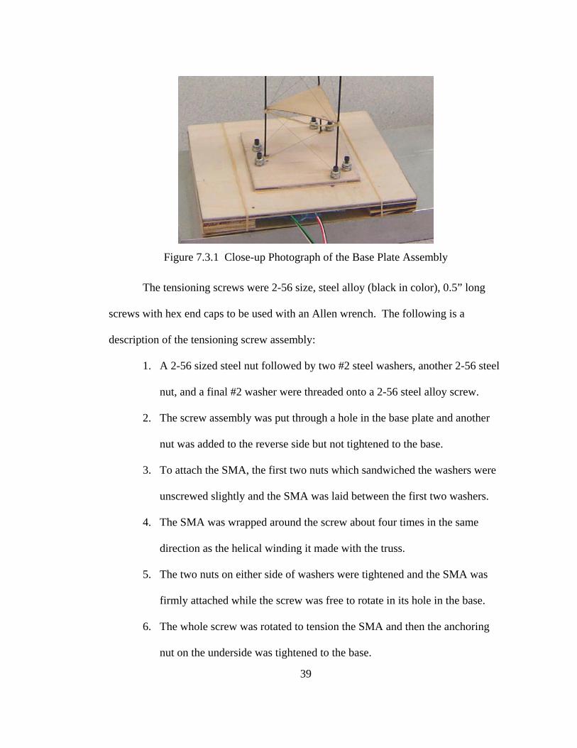
Figure 7.3.1 Close-up Photograph of the Base Plate Assembly
The tensioning screws were 2-56 size, steel alloy (black in color), 0.5” long
screws with hex end caps to be used with an Allen wrench. The following is a
description of the tensioning screw assembly:
1. A 2-56 sized steel nut followed by two #2 steel washers, another 2-56 steel
nut, and a final #2 washer were threaded onto a 2-56 steel alloy screw.
2. The screw assembly was put through a hole in the base plate and another
nut was added to the reverse side but not tightened to the base.
3. To attach the SMA, the first two nuts which sandwiched the washers were
unscrewed slightly and the SMA was laid between the first two washers.
4. The SMA was wrapped around the screw about four times in the same
direction as the helical winding it made with the truss.
5. The two nuts on either side of washers were tightened and the SMA was
firmly attached while the screw was free to rotate in its hole in the base.
6. The whole screw was rotated to tension the SMA and then the anchoring
nut on the underside was tightened to the base.
39

40
7. Then one wire of a three-wire cable was stripped of the insulation and
wound around the bottom end of the last nut with another 2-56 steel nut
tightened firmly down on top of the wire to secure it. Note that no bare
wire was left outside of the interface of nut and nut. Refer to section 7.4
for an explanation of the wiring of the SMA circuit.
7.4 BI-DIRECTIONAL ACTUATION
Both clockwise and counterclockwise windings of 0.005 inch diameter SMA
actuator wires were attached to the wire guides of the KEVLAR® trusses. Two
separate circuits were made: one with the three clockwise wound SMA wires and the
other with the three counterclockwise wound SMA wires. A different tri-wire cable
was connected to each set of clockwise or counterclockwise wires at each end. Tri-
wire cables which had a green wire in them were connected to the clockwise wound
SMAs, and tri-wire cables which had a red wire connected to the counterclockwise
wound SMAs. Red insulated alligator-type connecting clips were soldered to each of
the cables coming off of the end cap while black alligator-type connectors were
soldered to the cables from the base cap.
The black alligator connector of the green (clockwise SMA) cable was
connected to the negative terminal of the power supply. The red alligator connector of
the green cable was attached to the positive terminal of the power supply. This made a
circuit of three resisting SMA wires in parallel as in the initial design. Refer to the
section on the initial design for specific circuit setup.

41
VIII. SECOND DESIGN PHASE TESTING
The second design of the Shape Memory Alloy Robotic Truss was tested to
show twisting actuation and opposing twisting actuation of the same truss. Two
separate circuits were made. The set of clockwise SMA wires wound around the truss
were each attached at the anchor/cap end screws to one strand of a tri-wire cable with
a distinguishable green strand. The set of counterclockwise SMA wires wound around
the truss were likewise attached individually to a strand in the tri-wire cable with a red
strand. The green strand cable from the cap end of the truss (with a soldered red
alligator clip) attached mechanically to the positive terminal of a variable voltage
power supply. The other green strand cable from the base end of the truss (with a
soldered black alligator clip) attached mechanically to the negative terminal of the
variable voltage power supply. This created a parallel circuit of three SMA wires
acting as resistors. An ammeter internal to the power supply was connected to the
circuit in series and measured the input current in the circuit. A voltmeter internal to
the power supply was connected in parallel to the circuit to measure the voltage drop
of the entire circuit. The second circuit was made similarly by replacing the
corresponding alligator clips of the counterclockwise circuit to the same power supply
with internal ammeter and voltmeter.
42
Current was supplied to one circuit at a time to determine the maximum
twisting displacement in either direction. When a circuit was connected, current and
voltage were turned up in small increments from zero until the ammeter registered and
motion was observed. Leaving the power supply set to this current and voltage, the
circuits were alternated between clockwise and counter clockwise SMA sets. Then to
determine the maximum actuation, the current and voltage were increased by about
20% to increase the speed of actuation and to determine the maximum automated
actuation. The circuits were then tested alternately. Finally the circuits were
disconnected and the truss was manually twisted to determine the true absolute
maximum actuation of the truss itself. The experiment was videotaped and
photographed against a background graph board at approximately six inches behind
the truss to determine the maximum deflections.
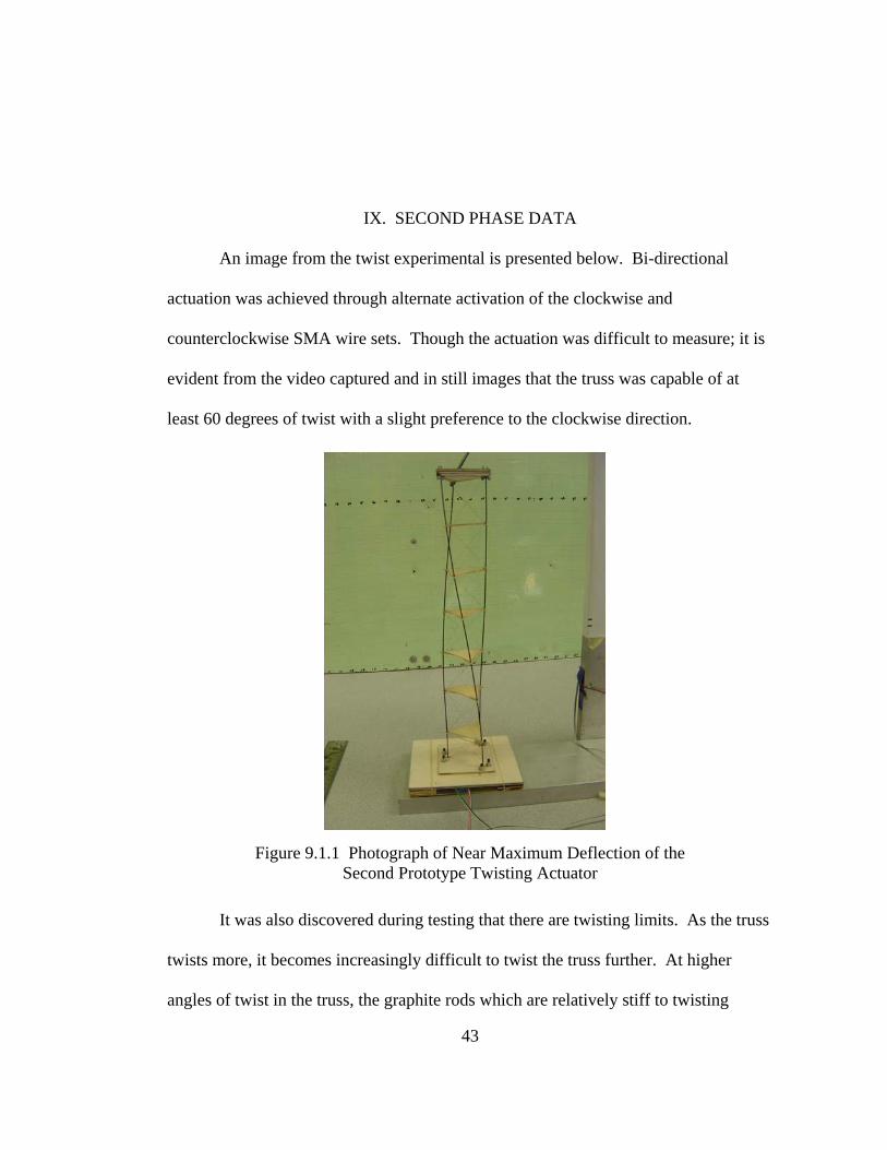
IX. SECOND PHASE DATA
An image from the twist experimental is presented below. Bi-directional
actuation was achieved through alternate activation of the clockwise and
counterclockwise SMA wire sets. Though the actuation was difficult to measure; it is
evident from the video captured and in still images that the truss was capable of at
least 60 degrees of twist with a slight preference to the clockwise direction.
Figure 9.1.1 Photograph of Near Maximum Deflection of the Second Prototype Twisting Actuator
It was also discovered during testing that there are twisting limits. As the truss
twists more, it becomes increasingly difficult to twist the truss further. At higher
angles of twist in the truss, the graphite rods which are relatively stiff to twisting
43

44
locally in themselves, must twist locally to allow the entire truss to twist. This can be
observed in the previous test image. At approximately 180 degrees of rotation, there
is also an interference problem with the graphite rods which point touch each other.
These conclusions of twist limitations were conducted by manual twisting of the truss
structure.

45
X. SECOND PHASE CONCLUSIONS
The goal of bi-directional actuation was achieved in this design using opposing
helical windings of SMA wires. This actuator prototype performed similarly to the
previous truss; however, there were some notable conclusions which fell out of the
testing. The sizing and stiffness of the rods and fixed ends of the truss affected the
amount of actuation achieved. The original triangular trusses of prepreg KEVLAR©
were inadequately stiff locally to prevent buckling. This required a redesign of the
triangles during testing to add a more a rigid plywood web. Redesign of the SMA
carrier triangles was noted as an opportunity for improvement in future prototyping.
During testing, it was shown that increasing the voltage and current above minimum
operational activation would increase the speed of the actuation; however, it would
probably lead to shorter fatigue life. Also, an important observation was made that the
more truss module segments in the truss, the more twist actuation is capable because
the amount of twist contributed by each truss cell is additive. Because there was
discovered a limitation on the amount of twist which can be achieved in this design, a
redesign of the support structure was recommended as essential to achieve better
twisting capabilities.
46
XI. THIRD DESIGN PHASE
The third design iteration marked a complete metamorphosis of the design with
the resulting third iteration resembling the earlier designs very little; however, the
essential technology behind the twisting actuation had changed very little. The third
design phase also added bending actuation capability to the twisting truss.
11.1 REDESIGN OF SMART CARRIER STRUCTURE
New consideration was give to the earlier Padget design which had utilized a
central graphite rod as a spine with equally spaced KEVLAR® squares with integrated
wire guides at the corners and cross members through the center to make a hole
through which the spine was placed and secured with cyanoacryllate. The third
iteration of SMART utilized Padget’s heritage application for a bending actuator with
SMA at four corners. Applying the lessons learned from the previous two SMART
iterations that KEVLAR® are not sufficiently stiff in compression for more than the
smallest scales, the wire guide structure was completely redesigned in a different
material. Prepreg fiberglass fabric was chosen as the new material for the SMA wire
carriers because of its increased compressive strength as well as for being an electrical
insulator.
Instead of using a graphite spine along which the square SMA carriers were
permanently affixed with cyanoacryllate, a steel rod of approximately 0.60 inches was

used. Further design influences came from nature and from snake vertebrae which
have a great deal of articulation due to the allowed rotation of their vertebrae in the
spinal column. Therefore, the fiberglass SMA carriers were allowed to rotate freely
about the central steel spine and were only constrained from translating along the
spine by the addition of collets on either side of the fiberglass vertebrae. When the
first prototype fiberglass vertebrae was produced, it was discovered that it did not slide
well about the steel spine because of the “brooming” delaminations which form as
holes are drilled; therefore steel washers just larger than the diameter of the steel spine
were added as inclusions in the layup to serve as crude bearings. There were no
observed delaminations around the modified vertebrae with steel washers for bosses as
is evident in the photograph of a finished vertebra. The steel washer bosses also
served as alignments for the templates to be affixed to the cured blanks.
Figure 11.1.1 Pattern for Fiberglass Vertebrae, left and Photograph of Finished Vertebra, right
Further design alterations were made to accommodate six holes for SMA wires
in each node instead of the original five. It was thought that by tying the SMA wires
to each vertebra that the force would be better transferred to the vertebra instead of
relying on contact with the rough drilled hole edge. Also, this method was developed
47

48
to maximize the pull force of each unit of the spine and allow each vertebra to work
equally. This concept was quickly abandoned when it was discovered that the wires
degraded rapidly from tying in such tight knots and the heating in the wires was not
uniform. The wires located at the ends were doing the most pulling. Rather than
remake the vertebrae for only three holes at each corner (one for bending wire,
clockwise twist, and counterclockwise twist), the vertebrae were used as is with
leaving three of the holes empty. The pull force of the wire was allowed to
equivalence itself along the entire length of the spine, and it was discovered that
bearing directly on the rough hole guides did not affect the wires significantly. It
should be noted as a risk that frequent chafing from the holes could cause premature
wear on the SMA wires. The inclusion of some sort of silicone inserts or grommets
would alleviate this chafing.
11.2 DETAILED CONSTRUCTION INFORMATION
Two SMARTs were made almost identically except that one was wired for
bending and the other for twisting. Both bending and twisting model SMARTs use
the same base components as follows:
A. Central Spine B. Fiberglass Vertebrae C. Collets D. End Cap Assembly E. Anchor Screws F. Base Assembly G. Tensioning Screws H. Shape Memory Alloy (SMA) Wires I. Electrical wiring

11.3 CENTRAL SPINE
The central spine is a steel rod with a diameter between 0.058 and 0.065
inches. One end of the steel rod is inserted into the base assembly and secured with
cyanoacryalate. See Section on Base Assembly. The other end of the rod is sharpened
to a point and mates with the End Cap. Refer to section on End Cap Assembly. See
photograph below.
Figure 11.3.1 Cap End of Central Spine
11.4 FIBERGLASS VERTEBRAE
“Clover-shaped” Fiberglass Vertebrae are located every three inches along the
Central Spine and simply supported by collets on either side. The individual vertebrae
are made from four plies of epoxy pre-impregnated fiberglass with a washer placed
middle layer to reinforce the central hole in the finished vertebrae. The blank lay-up is
placed between two caul plates and heated in an autoclave for two hours at 177°C.
Patterns are placed on the blank to align with the washers. Then the pattern is cut out
using a band saw, and the holes are drilled with a hand drill. The holes accommodate
49

the Shape Memory Alloy wires and act as electrical insulators between the Central
Spine and each SMA wire at the nodes. The Vertebrae slides onto the steel spine and
is secured between two Collets which prevent the vertebrae from translating. See
section 11.5 on collets.
Figure 11.4.1 Integrated Vertebrae on Central Spine
11.5 COLLETS
The Collets are appropriately sized to fit over the steel Central Spine and
contain set screws which tighten them onto the steel spine. The set screws will either
require a jeweler’s screwdriver or appropriate sized hex key/Allen key. Collets may
be purchased at a hobby supply store. Each Fiberglass Vertebrae is sandwiched
between two collets to prevent translation up or down the Central Spine. Please note
that the Collets do not prevent rotation.
50
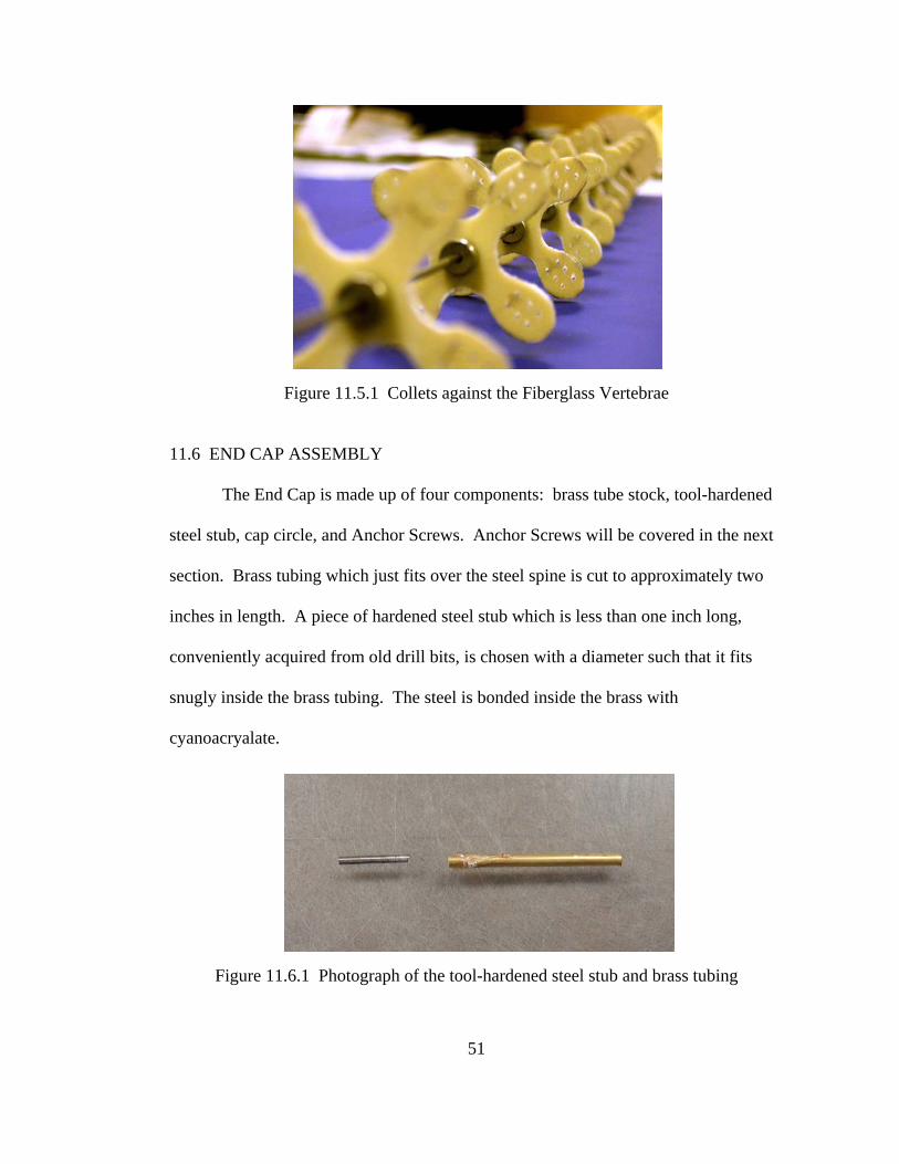
Figure 11.5.1 Collets against the Fiberglass Vertebrae
11.6 END CAP ASSEMBLY
The End Cap is made up of four components: brass tube stock, tool-hardened
steel stub, cap circle, and Anchor Screws. Anchor Screws will be covered in the next
section. Brass tubing which just fits over the steel spine is cut to approximately two
inches in length. A piece of hardened steel stub which is less than one inch long,
conveniently acquired from old drill bits, is chosen with a diameter such that it fits
snugly inside the brass tubing. The steel is bonded inside the brass with
cyanoacryalate.
Figure 11.6.1 Photograph of the tool-hardened steel stub and brass tubing
51

Next, a piece of “light-ply” hobbiest’s plywood with about a 1/8 inch thickness
is cut into a disc with a diameter of approximately two inches. A depression is made
into the center of the disc to accept the brass/steel stub assembly. The brass/steel
assembly is bonded with cyanoacryalate to the End Cap. A filet of cyanoacryalate is
made at the joint to make the connection much stronger. A filet may be made by
applying a cyanoacryalate accelerating spray and cyanoacryalate epoxy in alternating
layers to build up a filet. Holes are drilled for the Anchor Screws according to the
same pattern as the Fiberglass Vertebrae; however, only a single hole is drilled per
pair in the pattern.
Figure 11.6.2 Photograph of the Finished End Cap Assembly
Graphite lubricating dust, commonly used to lubricate locks and is available in
any hardware store, is put into the brass tubing to allow smooth rotation when the End
Cap Assembly is mounted to the sharpened end of the steel spine. Please note that
because the Steel Spine only contacts the End Cap Assembly at the sharpened point
52

and graphite lubrication reduces friction, the End Cap Assembly acts like a frictionless
bearing and is free to rotate.
Figure 11.6.3 Photograph of End Cap Mating with End of Central Spine
Please note, the first bending model of S.M.A.R.T. does not have a brass tubing/steel
stub on the End Cap Assembly. The end of the Steel Spine simply fit into a hole
drilled halfway though the End Cap. This constrains the rotational degree of freedom
at the End Cap; however, the bending actuation of the S.M.A.R.T. does not create any
torsion on the end. As a result, rotation at the end cap is insignificant for the bending
model, and the basic End Cap is sufficient for the Bending S.M.A.R.T.
11.7 ANCHOR SCREWS
The Anchor Screws are the attachment nodes for the Shape Memory Alloy
(SMA) wires at the End Cap Assembly. The Anchor Screws are 0-80 steel alloy
(black in color) screws that are 1 inch in length and have a hex cap head for use with
53
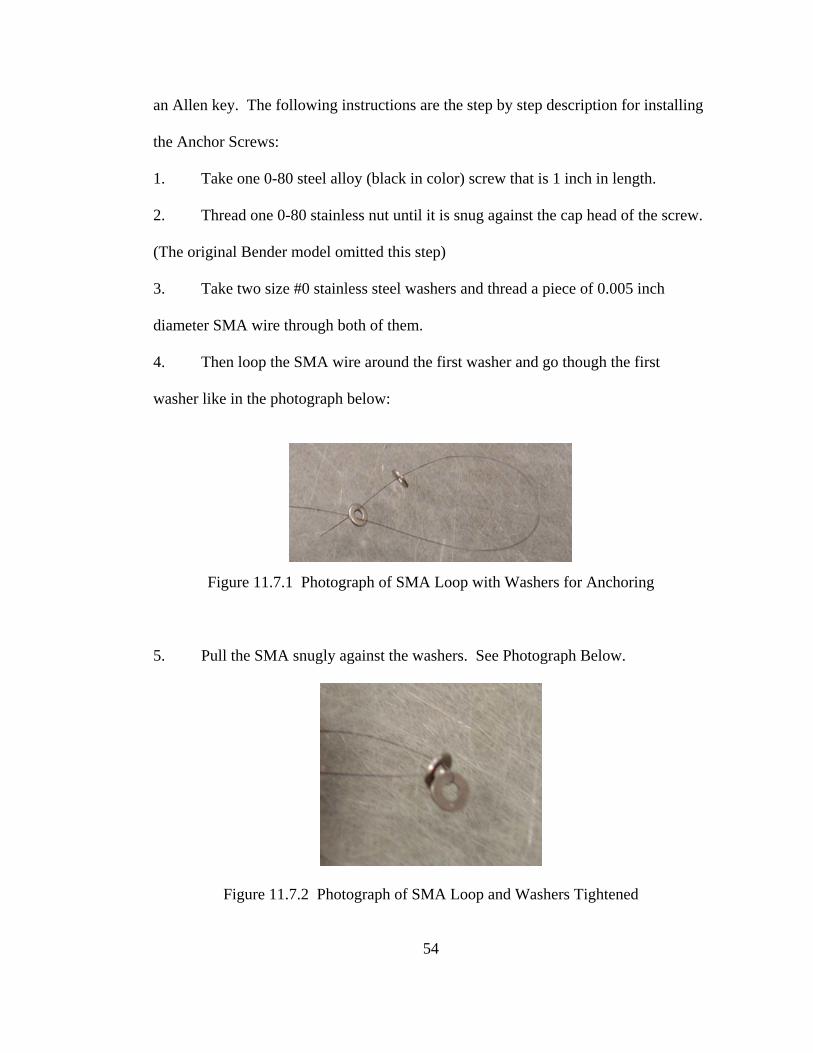
an Allen key. The following instructions are the step by step description for installing
the Anchor Screws:
1. Take one 0-80 steel alloy (black in color) screw that is 1 inch in length.
2. Thread one 0-80 stainless nut until it is snug against the cap head of the screw.
(The original Bender model omitted this step)
3. Take two size #0 stainless steel washers and thread a piece of 0.005 inch
diameter SMA wire through both of them.
4. Then loop the SMA wire around the first washer and go though the first
washer like in the photograph below:
Figure 11.7.1 Photograph of SMA Loop with Washers for Anchoring
5. Pull the SMA snugly against the washers. See Photograph Below.
Figure 11.7.2 Photograph of SMA Loop and Washers Tightened
54
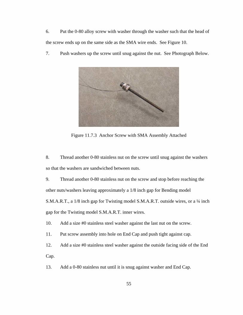
6. Put the 0-80 alloy screw with washer through the washer such that the head of
the screw ends up on the same side as the SMA wire ends. See Figure 10.
7. Push washers up the screw until snug against the nut. See Photograph Below.
Figure 11.7.3 Anchor Screw with SMA Assembly Attached
8. Thread another 0-80 stainless nut on the screw until snug against the washers
so that the washers are sandwiched between nuts.
9. Thread another 0-80 stainless nut on the screw and stop before reaching the
other nuts/washers leaving approximately a 1/8 inch gap for Bending model
S.M.A.R.T., a 1/8 inch gap for Twisting model S.M.A.R.T. outside wires, or a ¼ inch
gap for the Twisting model S.M.A.R.T. inner wires.
10. Add a size #0 stainless steel washer against the last nut on the screw.
11. Put screw assembly into hole on End Cap and push tight against cap.
12. Add a size #0 stainless steel washer against the outside facing side of the End
Cap.
13. Add a 0-80 stainless nut until it is snug against washer and End Cap.
55

Figure 11.7.4 Completed Anchor Screw Assembly
14. Check to see that the SMA wire is firmly attached to the screw assembly and
that the screw assembly is firmly attached to the End Cap.
15. For electrical contacts, it may be desirable to add another 0-80 nut to the screw
with a 1/8 inch gap. Then add an electrical lead, as pictured above, and secure with
another nut. This step may be modified accordingly or omitted as in the case of
alligator type electrical connectors.
11.8 BASE ASSEMBLY
The Base Assembly consists of a base block which is about 4 inches long with
embedded 2-56 plated nuts for 2-56 steel alloy (black in color) Tension Screws and a
Mounting Base Plate. The end of the Central Spine attaches to the Base Assembly in a
hole drilled into the top of the block. The joint is secured using cyanoacryalate in the
hole and a filet of cyanoacryalate around the outside of the joint. The filet is made
56
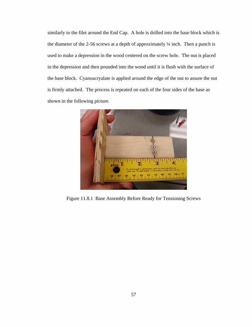
similarly to the filet around the End Cap. A hole is drilled into the base block which is
the diameter of the 2-56 screws at a depth of approximately ¼ inch. Then a punch is
used to make a depression in the wood centered on the screw hole. The nut is placed
in the depression and then pounded into the wood until it is flush with the surface of
the base block. Cyanoacryalate is applied around the edge of the nut to assure the nut
is firmly attached. The process is repeated on each of the four sides of the base as
shown in the following picture.
Figure 11.8.1 Base Assembly Before Ready for Tensioning Screws
57
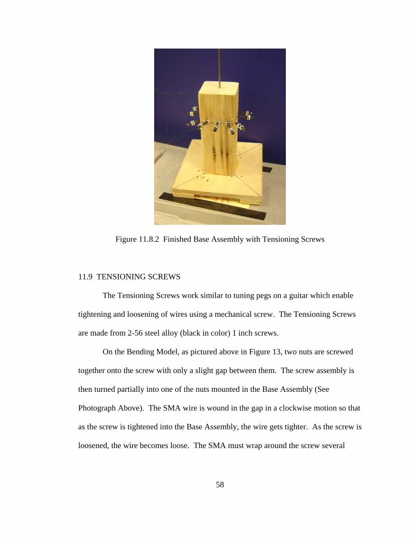
Figure 11.8.2 Finished Base Assembly with Tensioning Screws
11.9 TENSIONING SCREWS
The Tensioning Screws work similar to tuning pegs on a guitar which enable
tightening and loosening of wires using a mechanical screw. The Tensioning Screws
are made from 2-56 steel alloy (black in color) 1 inch screws.
On the Bending Model, as pictured above in Figure 13, two nuts are screwed
together onto the screw with only a slight gap between them. The screw assembly is
then turned partially into one of the nuts mounted in the Base Assembly (See
Photograph Above). The SMA wire is wound in the gap in a clockwise motion so that
as the screw is tightened into the Base Assembly, the wire gets tighter. As the screw is
loosened, the wire becomes loose. The SMA must wrap around the screw several
58

59
times and the nuts must be tightened together for the SMA wire to be secured
by friction.
The Twisting Model works similarly to the Bending Model with the addition
of two washers between the nuts which give more surface area to clamp onto the
SMA wire.
Tension should be relatively close in each of the wires and may be felt by
touching the wires. The wires should not have any slack but should not be so tight
that the S.M.A.R.T. is almost rigid.
11.10 SHAPE MEMORY ALLOY (SMA) WIRES
Nickel Titanium Shape Memory Alloy Wires with a transition temperature of
70°C and a diameter of 0.005 inches are used. Wires should be cut to approximately
42 inches to insure overrun. Please refer to directions about Anchor screws and
Tensioning Screws for instructions on how to connect the wires.
On the Bending Model, wires run linearly from one node to the next in the
same corresponding hole. On the Twisting Model, sets of wires run clockwise and
counterclockwise as in Figure 11.10.1. The inner set of wires use Teflon tubing
inserted over the wires in the stringing process. The tubing is approximately 2/3 of
the length of the exposed wire length nodes.

60
Figure 11.10.1 SMA Wires on the Twisting Model of the SMART
11.11 ELECTRICAL CIRCUIT
Power is supplied to the SMA wires by a manual power supply. Tandem
pulling SMA wires are connected in parallel. This means that pairs of wires on the
Bending model are wires in parallel, and the four outer wires on the Twisting model
are wired in parallel separately from the four inner wires on the Twisting model which
are wired together in parallel.
Power Requirements for the S.M.A.R.T.’s are as follows: For the Bending
Model, a current not exceeding 1 amp is supplied at a voltage of between 30 and 35
volts. For the Twisting Model, a current not exceeding 1 amp is supplied at a voltage
of around 30 volts.

61
XII. GROUND AND REDUCED GRAVITY FINAL TESTING
The ground based tests of both the twisting and bending were conducted using
nearly identical setups as the previous iterations of SMART. The actuation modes
were tested separately on identical SMARTs with one wired with helical SMA for
twisting and the other wired linearly for bending. This was done to accommodate the
need for redundant test articles for two days of testing aboard the NASA C-9 aircraft.
If one SMART failed, the other would be ready to go that day and be available for
reworking to accommodate the other mode testing during the night between flights. A
third truss structure was made; however, it was not wired and was there in case spare
parts were needed or could be wired in case both trusses failed or the flown truss could
not be reworked.
In ground based testing, SMART was suspended by its base which was
clamped in a fixture. A graph board was placed just behind SMART so that
displacements could be measured from still and video images taken of the truss.
Additionally, a mirror was mounted to the tip of the truss and a laser beam bounced
off of the mirror onto a graph board to measure deflections of the tip of SMART more
accurately.
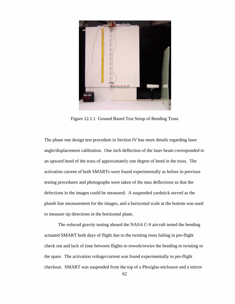
Figure 12.1.1 Ground Based Test Setup of Bending Truss
The phase one design test procedure in Section IV has more details regarding laser
angle/displacement calibration. One inch deflection of the laser beam corresponded to
an upward bend of the truss of approximately one degree of bend in the truss. The
activation current of both SMARTs were found experimentally as before in previous
testing procedures and photographs were taken of the max deflections so that the
defections in the images could be measured. A suspended yardstick served as the
plumb line measurement for the images, and a horizontal scale at the bottom was used
to measure tip directions in the horizontal plane.
The reduced gravity testing aboard the NASA C-9 aircraft tested the bending
actuated SMART both days of flight due to the twisting truss failing in pre-flight
check out and lack of time between flights to rework/rewire the bending to twisting or
the spare. The activation voltage/current was found experimentally in pre-flight
checkout. SMART was suspended from the top of a Plexiglas enclosure and a mirror 62

63
was mounted on the tip of SMART to reflect the laser beam onto a graph board.
Smart was manually turned on just before the 30 seconds of parabolic path freefall for
approximately 60 cycles of parabolas per flight. Digital video equipment continuously
captured movements of the reflected laser point as SMART actuated and stored the
video to the hard drive of a laptop in the test enclosure. The enclosure was mounted
on four large dampers so that vibrations from the C-9 aircraft would have less effect
on the data. The detailed circuit, test setup, photographs from the flights, as well as
the operations manual for SMART for the reduced gravity testing by the Auburn
University NASA Reduced Gravity Student Team is available in the Appendix.
64
XIII. GROUND AND REDUCED GRAVITY TEST DATA
The two SMARTs were tested in ground based tests. Both SMARTs were
slated to fly aboard the NASA C-9 aircraft in reduced gravity; however, due to
technical difficulty, the Twisting SMART was scratched and the Bending SMART
was flown on both days of flight on March 9-10, 2006 at NASA Johnson in Houston,
Texas. The members of the Auburn University team who performed the in flight
operations of SMART were Michael Brennison, Ryan Leureck, Megan Brown, and
Vanessa Smith, Andrew Wright and Christopher Worley served as ground crew and
backup crew for flight operations.
13.1 BENDING SMART GROUND TEST
In testing the bending truss, the laser beam left the graph board before max
deflection. Also, because of the high deflection of the tip of SMART, the laser beam
no longer focused on the mirror. The still image of bending SMART at maximum
actuation shows a tip deflection of 13.5 inches in the horizontal and a tangent angle of
the tip section of 58 degrees from the vertical yellow yardstick. Measurements were
calculated from image processing of the photograph taken at maximum deflection
from a camera mounted perpendicular to test plane.

5º
13.5”
58º
Figure 13.1.1 Photograph of SMART at Maximum Bending Deflection With and Without Displacement Measurements on Image
The base of SMART was observed to rotate in its fixture. Using the same
photograph captured at maximum bending deflection, the angle deflected by the base
was measured. The 5 º deflection of the base was added to the tip deflection of 58º
which resulted in a total truss deflection of 63º in bending.
Following the bending test, there was an observable post-test residual
deformation of the truss. The residual tip deflection was 1.5 inches from pretest and a
bending angle residual of 7º. Repeating the test consistently yielded the same
deflection and residual post deflection.
65
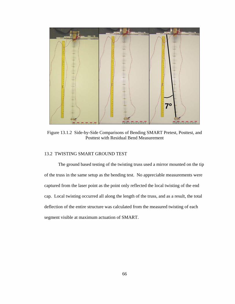
7º
Figure 13.1.2 Side-by-Side Comparisons of Bending SMART Pretest, Posttest, and Posttest with Residual Bend Measurement
13.2 TWISTING SMART GROUND TEST
The ground based testing of the twisting truss used a mirror mounted on the tip
of the truss in the same setup as the bending test. No appreciable measurements were
captured from the laser point as the point only reflected the local twisting of the end
cap. Local twisting occurred all along the length of the truss, and as a result, the total
deflection of the entire structure was calculated from the measured twisting of each
segment visible at maximum actuation of SMART.
66

Figure 13.2.1 Photograph of Twisting Truss At Maximum Deflection Posttest.
(Photograph is Rotated 90 Degrees Counterclockwise)
Figure 13.2.1 Photograph of Twisting Truss At Maximum Deflection Posttest.
(Photograph is Rotated 90 Degrees Counterclockwise)
Table 13.2 Twisting of SMART per SEGMENT Table 13.2 Twisting of SMART per SEGMENT
SegmentSegment Node From Node From Node To Node To Deflection Deflection 1 Base Vertebra 1 0º 2 Vertebra 1 Vertebra 2 75º 3 Vertebra 2 Vertebra 3 15º 4 Vertebra 3 Vertebra 4 45º 5 Vertebra 4 Vertebra 5 45º 6 Vertebra 5 Vertebra 6 30º 7 Vertebra 6 Vertebra 7 90º 8 Vertebra 7 Vertebra 8 75º 9 Vertebra 8 Vertebra 9 90º 10 Vertebra 9 Vertebra 10 90º 11 Vertebra 10 Vertebra 11 90º 12 Vertebra 11 End Cap 90º
TOTAL TWISTING DEFLECTION: 735º
Figure 13.2.2 Plot of Twisting of SMART per Segment
Twisting of SMART Per Segment
0102030405060708090
100
0 1 2 3 4 5 6 7 8 9 10 11 12 13Segment Number
Def
lect
ion
in D
egre
es
67
68
13.3 BENDING SMART REDUCED GRAVITY TEST
The Bending SMART flew aboard the NASA C-9 Aircraft and operated safely.
Post flight analysis of the structure certified that the structure remained intact for the
entire flight and still maintained mechanical functionality following reduced gravity
operations. Observations from the flight test crew indicated that SMART worked as
anticipated and experienced bending deflections of more than 90 degrees during
reduced gravity sets. The video captured in-flight did not have an adequate frame of
reference to measure true deflection of SMART from normal. What can de derived
from the film is that there was a gain of approximately 12 degrees in the max
deflection during the reduced gravity sets when compared to the max deflection in
normal gravity. This was measured from the deflection of the laser beam on a
graphboard between max deflection at constant gravity and max deflection at reduced
gravity.

69
XIV. SMART PROGRAM CONCLUSIONS
There were many strides as well as many lessons learned over the course of
SMART development, and the final SMART design benefits from both. SMART
successfully satisfied the fit, form, and function of a degree of deflection bending and
twisting actuator. Ground based testing produced approximately 70 degrees bending
and a little over 2 full rotations of the structural components. Further reduced gravity
testing of SMART in bending resulted in additional bending by conservative estimates
of more than 10 degrees. Successful flight tests aboard the NASA C-9 aircraft
certified SMART as a reduced gravity actuator and raised the design’s technology
readiness level one step closer to space operations and the transition from prototype to
production.
Further design refinements to be considered in the future are: to find a better
method of electrical insulation for SMA wires that will not hinder even heating of the
wires, work out actuation control to achieve intermediate actuation, integrating
operations of bending and twisting in tandem on a single SMART, creating a
mathematical model to further explore the additive effects of segment actuation of a
chain of segments, and studying out-gassing of materials in SMART and considering
using materials which would be more suitable in a vacuum and under very hot and
very cold temperatures.
70
REFERENCES
1. Fromer, J., Sectionally Heated Shape Memory Alloy Actuator for Multiple Position Aircraft Roll Control, M.S. Thesis, Auburn University, Auburn, Alabama, 2002. 2. Srinivasan, A. V., and McFarland, D. M., Smart Structures: Analysis and Design, Cambridge University Press, Cambridge, United Kingdom, 2001, pp. 26-72 3. Schwartz, M., Encyclopedia of Smart Materials, John Wiley & Sons, Inc., New York, New York, Vol.2, 2002, p. 923. 4. Barrett, R. M., Introduction to Adaptive Aerostructures, Short Course Presented at Auburn University, May 2003. 5. Howard, N. A. Design, Construction, and Analysis of a 2-Degree-Of-Freedom Shape Memory Alloy Rotary Actuator, M.S. Thesis, Auburn University, Auburn, Alabama, 2000.
6. Padgett, D. A. The Design and Construction of a Shape Memory Alloy Tail Boom Actuator. 41st Aerospace Sciences Meeting and Exhibit. 6-9 January 2003, Reno, Nevada 7. Otsuka, K. and Wayman, C. Shape Memory Materials, Cambridge University Press, Cambridge, United Kingdom, 1999. 8. Banks, H., Smith, R., and Wang, Y., Smart Material Structures: Modeling, Estimation, and Control, John Wiley & Sons, Inc., New York, New York, 1996, pp. 18-26. 9. Dynalloy Co. Web Page, http://www.sma-inc.com/Actuator.html, 2004. 10. Kelly, A., Concise Encyclopedia of Composite Materials, MIT Press, Cambridge, Massachusetts, 1989, pp 33-35. 11. Hibbler, R., Mechanics of Materials, Prentice Hall, Upper Saddle River, New Jersey, 2000, p. 92.

71
APPENDIX A
PROPERTIES OF SHAPE MEMORY ALLOYS
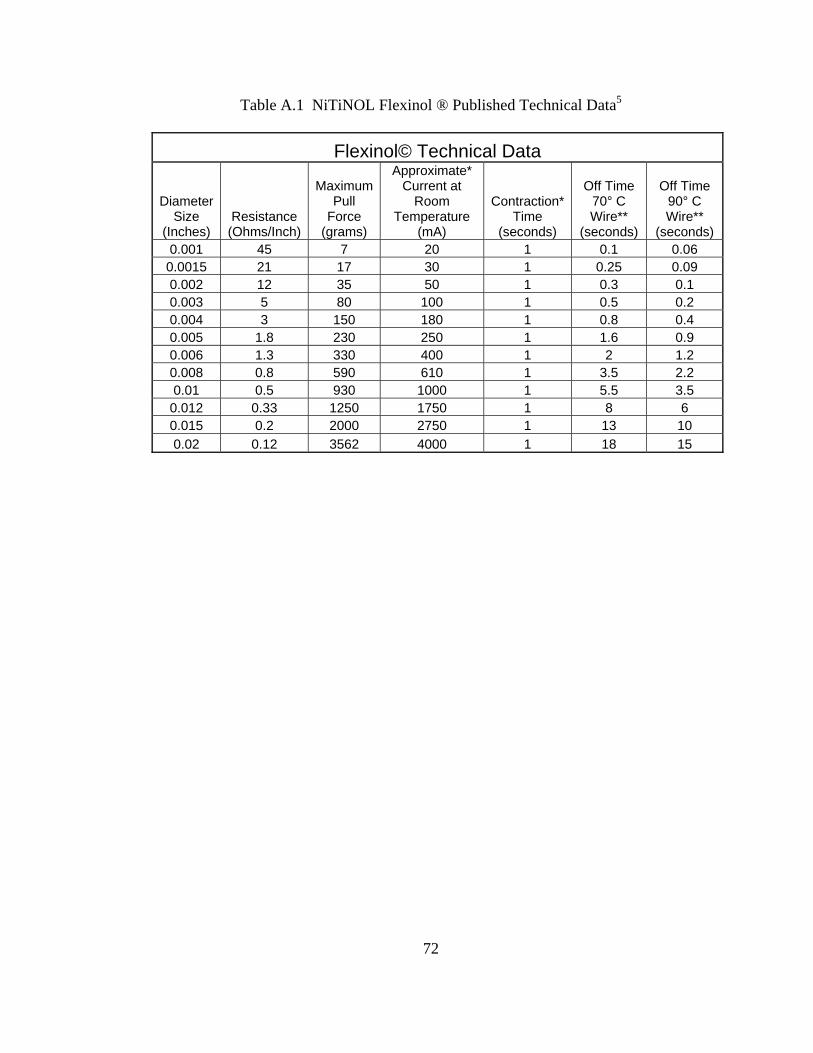
72
Table A.1 NiTiNOL Flexinol ® Published Technical Data5
Flexinol© Technical Data
Diameter Size
(Inches) Resistance (Ohms/Inch)
Maximum Pull
Force (grams)
Approximate* Current at
Room Temperature
(mA)
Contraction* Time
(seconds)
Off Time 70° C Wire**
(seconds)
Off Time 90° C Wire**
(seconds) 0.001 45 7 20 1 0.1 0.06 0.0015 21 17 30 1 0.25 0.09 0.002 12 35 50 1 0.3 0.1 0.003 5 80 100 1 0.5 0.2 0.004 3 150 180 1 0.8 0.4 0.005 1.8 230 250 1 1.6 0.9 0.006 1.3 330 400 1 2 1.2 0.008 0.8 590 610 1 3.5 2.2 0.01 0.5 930 1000 1 5.5 3.5
0.012 0.33 1250 1750 1 8 6 0.015 0.2 2000 2750 1 13 10 0.02 0.12 3562 4000 1 18 15

73
Table A.2 Typical Properties of NiTiNOL SMA Alloys2
Typical Properties of NiTiNOL Alloys
Physical Properties
Melting Point 1300 °C Density 6.45 g/cm^3 0.233 lb/in^3 Electrical Resistivity: Austenite ~100 μΩcm Martensite ~70 μΩcm Thermal Conductivity: Austenite 0.18 W/cm°C Martensite 0.085 W/cm°C
Similar to 3000 Series
Corrosion Resistance Stainless Steel or Ti Alloys
Mechanical Properties
Young's Modulus: Austenite ~12E6 psi Martensite ~4.6E6 psi Yield Strength: Austenite 28-100E3 psi Martensite 10-20E3 psi Ultimate Strength 130E3 psi Elongation Failure 20-30 %
Transformation Properties
Transformation Temperature -100 to 200 °C Latent Heat of Transformation 40 cal/g atom Shape Memory Strain 8.4% Maximum

74
APPENDIX B
PHOTOGRAPHS OF TEST SETUP
FOR FIRST DESIGN ITERATION

Figure B.1 Photograph of Test Setup Showing Laser, Test Stand, and DC Power Supply
Figure B.2 Enhanced photograph of the SMA Truss on the Test Stand. The Dark Lines Trace the Boron Filaments. The Lighter Gray Lines trace the SMA Wires
75

76
Figure B.3 Close-up Photograph of the Torsional Strain Relief Device Which is the White Coil in the Photograph
Figure B.4 Photograph of Test Setup with Test Stand, Laser, and Wall Graph Board

77
APPENDIX C
PHOTOGRAPHS FROM SECOND DESIGN ITERATION
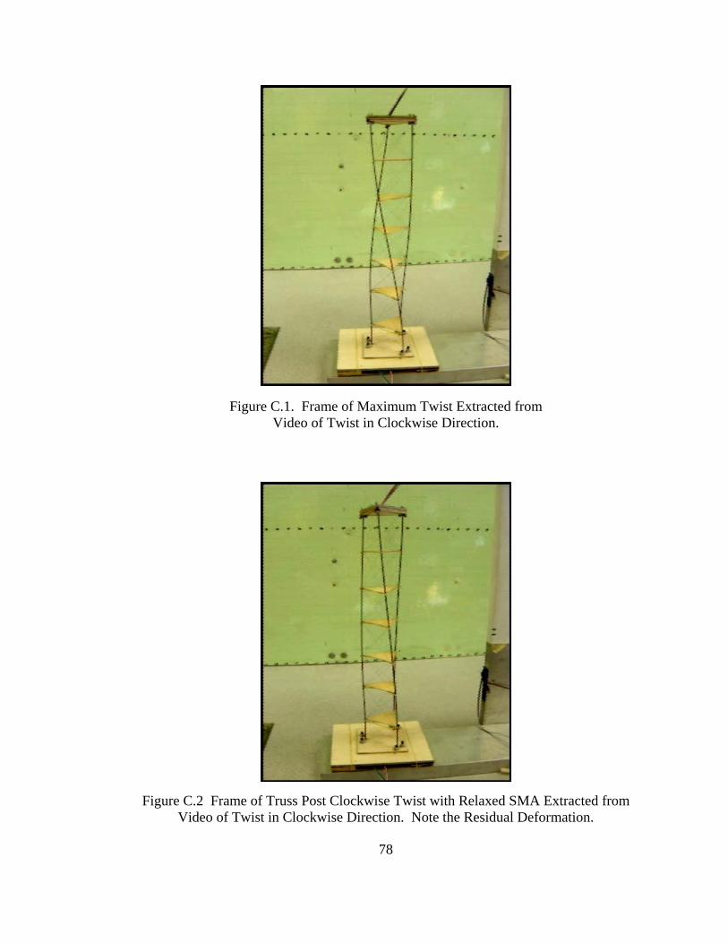
Figure C.1. Frame of Maximum Twist Extracted from Video of Twist in Clockwise Direction.
Figure C.2 Frame of Truss Post Clockwise Twist with Relaxed SMA Extracted from
Video of Twist in Clockwise Direction. Note the Residual Deformation.
78
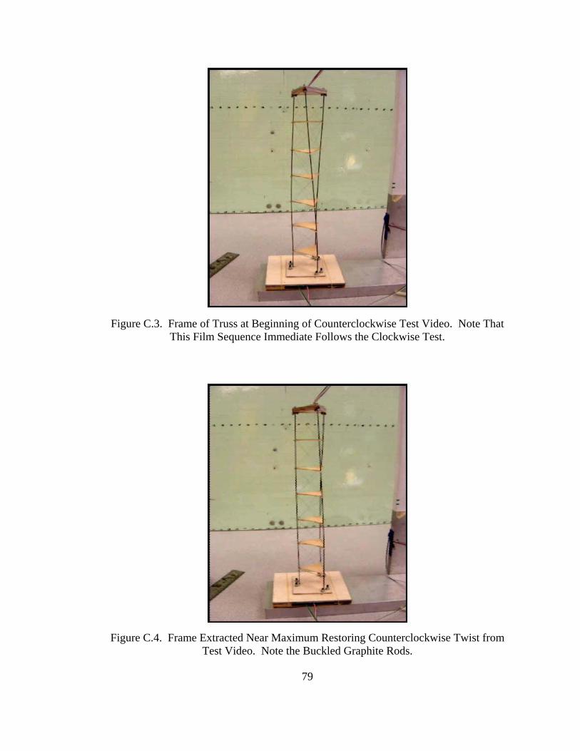
79
Figure C.3. Frame of Truss at Beginning of Counterclockwise Test Video. Note That
This Film Sequence Immediate Follows the Clockwise Test. Figure C.4. Frame Extracted Near Maximum Restoring Counterclockwise Twist from
Test Video. Note the Buckled Graphite Rods.

80
APPENDIX D
PHOTOGRAPHS OF POSTTEST
OF FINAL SMART TWISTING TRUSS

0 degrees
75 degrees
15 degrees
45 degrees
90 degrees
90 degrees
90 degrees
45 degrees
75 degrees
90 degrees
90 degrees
30 degrees
0 degrees
75 degrees
15 degrees
45 degrees
90 degrees
90 degrees
90 degrees
45 degrees
75 degrees
90 degrees
90 degrees
30 degrees
Figure D.1. Final Iteration of Twisting Smart Posttest with Measurements of Twist
Note that the nodes were color coded such that at high magnification, one can
discern the rotation. Also, several wires fractured in the test, so the degree of twist
was likely more than in the posttest photograph.
81

82
Figure D.2 Close-up Photograph of Twisting SMART with Color Coding Evident
Figure D.3 Researcher Lori Prothero with the Posttest SMART

83
APPENDIX E
REDUCED GRAVITY TESTING OF SMART IN BENDING

84
SMART Reduced Gravity Testing Proposal Abstract Reprinted from Microgravity University
http://microgravityuniversity.jsc.nasa.gov/theArchives
Auburn University 2006 Shape Memory Alloy Robotic Truss Shape Memory Alloys (SMA) belong to a special class of metals with a unique crystalline structure that can be heat trained to remember a specific size or shape, which it will return to when a heat stimulus is applied. Because of the ability to stretch and shrink repeatedly with strain recovery, SMA are the ideal materials for mechanical devices that perform repetitive tasks, or actuators. An actuator, as the name implies, is a mechanical device which causes something else to move.4 Actuators can be composed of a large number of moving parts such as gears and hydraulic pistons. The light-weight and simplicity of shape memory alloys have made them a great alternative to conventional actuator systems. SMA have the capacity to reduce the complexity of an actuator by replacing many moving parts with a few strands of SMA wire. This reduces spacecraft actuator mass, which can be significant to reducing launch costs. Replacing hydraulic pistons and gears with a single wire also reduces the vibrational settling time, or shaking, as the actuator moves, causing hydraulically mechanized machines to be imprecise in their movements.4 As a result, vibration is a major limiting factor in robotic design, especially in a space environment because it has fewer media to help dampen the undesired movement. Two proof-of-concept designs previously completed by team members show the feasibility of SMA actuation, both linearly and torsionally. The overall goal of Team SMART is to build and test two fully functional SMA actuated Remote Manipulator Systems (RMS’s) designed to function in a reduced gravity environment. The team will then compare mechanical characteristics including fatigue life, nodal deflections, total deflections, force, stress, and coiling phenomena between gravitational field and reduced gravity environments. The testing will increase the technological readiness level for SMA spaceflight actuated devices and will help to develop a correlation factor for linear actuation and coiling phenomena.

Figure E.1. Auburn University “Vomit Comet” Team at Team Readiness Review Team Members (Left to Right): Meghan Brown, Chris Worley, Unknown Girl Not on
Team, Vanessa Smith, Andrew Wright, Ryan Lureck, Michael Brennison
85
Figure E.2. Team Readiness Review Presentation with SMART Test Module at Right

Figure E.3. Demonstration of SMART Operations Inside Plexiglas Enclosure with NASA C-9 Aircraft in Background
Figure E.4. Unpacking and Presentation of Twisting SMART at Team Readiness Review
86

87
Figure E.5. Team Preflight Physiological Testing in Altitude Simulator
Figure E.6. Andrew Wright during Physiological Test

Figure E.7. Flight Crew and Flyers from March 9, 2006 at Johnson Space Center in Houston, Texas flight aboard the NASA C-9 Reduced Gravity Aircraft
Figure E.8. Ryan SMART Flyers Leureck and Vanessa Smith from March 9, 2006 Flight
88

Figure E.9. Andrew Wright, Backup Flyer for SMART Received Opportunity to Fly with Experiment from Another University on March 9, 2006
89
Figure E.10. Ryan Leureck During Reduced Gravity Flight on March 9, 2006

Figure E.11. Andrew Wright During Reduced Gravity Flight on March 9, 2006
Figure E.12. Ryan Leureck and Vanessa Smith Operating SMART During Reduced Gravity Parabola on March 9, 2006
90

Figure E.13. Vanessa Smith and Ryan Leureck Observing SMART During Reduced Gravity Parabola on March 9, 2006
Figure E.14. Vanessa Smith and Ryan Leureck Observing SMART Through Top of Plexiglass Enclosure on March 9, 2006
91

Figure E.15. Flight Crew and Flyers from March 10, 2006 at Johnson Space Center in Houston, Texas flight aboard the NASA C-9 Reduced Gravity Aircraft
Figure E.16. Smart Flyers Michael Brennison and Meghan Brown with SMART Test Module on March 10, 2006 Flight
92

Figure E.17. Smart Flyers Michael Brennison and Meghan Brown During Reduced Gravity Flight on March 10, 2006
Figure E.18. Meghan Brown During Reduced Gravity on March 10, 2006
93

94
Figure E.19. Michael Brennison Checking Computer In Flight on March 10, 2006
Figure E.20. Meghan Brown Checking SMART Bending Truss Experiment Through Plexiglass Top of Experiment Enclosure on March 10, 2006.