Embed Size (px)
Citation preview
Application of high-order FEM to the P-wave propagation
around and inside an underground cavity
Journal: Geophysics
Manuscript ID GEO-2016-0447.R2
Manuscript Type: Technical Paper
Date Submitted by the Author: 03-Apr-2017
Complete List of Authors: Esterhazy, Sofi; Universitat Wien Fakultat fur Mathematik, ; Universitat Wien Fakultat fur Geowissenschaften Geographie und Astronomie, Departement of Meteorology and Geophysics Schneider, Felix; Universitat Wien Fakultat fur Geowissenschaften Geographie und Astronomie, Department of Meteorology and Geophysics Perugia, Ilaria; Universitat Wien Fakultat fur Mathematik
Bokelmann, Götz; University of Vienna, Department of Meteorology and Geophysics
Keywords: compressional wave (P-wave), finite element, frequency-domain, wave equation, two-dimensional
Area of Expertise: Seismic Modeling and Wave Propagation, Geophysical Software and Algorithms
Note: The following files were submitted by the author for peer review, but cannot be converted to PDF. You must view these files (e.g. movies) online.
Table1.tex
GEOPHYSICS
This paper presented here as accepted for publication in Geophysics prior to copyediting and composition. © 201 Society of Exploration Geophysicists.7
Dow
nloa
ded
06/1
2/17
to 1
31.1
30.1
57.1
41. R
edis
trib
utio
n su
bjec
t to
SEG
lice
nse
or c
opyr
ight
; see
Ter
ms
of U
se a
t http
://lib
rary
.seg
.org
/

Application of high-order FEM to the P-wave
propagation around and inside an underground
cavity
Sofi Esterhazy1,2, Felix Schneider2, Ilaria Perugia1, Gotz Bokelmann2
1
University of Vienna, Faculty of Mathematics, Vienna, Austria.
E-mail: [email protected], [email protected]
2
University of Vienna, Faculty of Earth Sciences, Geography and Astronomy,
Department of Meteorology and Geophysics, Vienna, Austria
E-mail: [email protected], [email protected]
(April 20, 2017)
GEO-2016-0447
Running head: Wave propagation around a cavity
ABSTRACT
In this paper we study the scattering of P-waves from an acoustic inclusion in a 2D
half-space with free surface. The motivation for this study comes from detecting a
cavity which might be caused by a underground nuclear explosion (UNE). This is
relevant to the On-Site Inspection (OSI), an element of the Comprehensive Nuclear-
Test Ban Treaty (CTBT). The waveform modeling we address is implemented in the
frequency domain, i.e. we consider the wavefield as well as the source to be time-
harmonic. We numerically investigate the cases where the source of the scattered
1
Page 1 of 38 GEOPHYSICS
123456789101112131415161718192021222324252627282930313233343536373839404142434445464748495051525354555657585960
This paper presented here as accepted for publication in Geophysics prior to copyediting and composition. © 201 Society of Exploration Geophysicists.7
Dow
nloa
ded
06/1
2/17
to 1
31.1
30.1
57.1
41. R
edis
trib
utio
n su
bjec
t to
SEG
lice
nse
or c
opyr
ight
; see
Ter
ms
of U
se a
t http
://lib
rary
.seg
.org
/

field is either a plane wavefrom the bottom or the side as from a passive sources
like teleseismic waves or ambient noise or a spherical wavefrom the surface as from
an active point sources like a vibroseis or an explosion. To this end we split the
total field in an incident and an unknown scattered field in order to understand the
e↵ects more explicitly. Modeling the response of a void in a medium is not trivial
and many numerical algorithms commonly used for seismic propagation modeling will
fail. We want to highlight therefore the advantage of high-order methods for this
type of applications in general and demonstrate the benefit by using the FEM code
Ngsolve. This is in particular the case for the situation we have at hand where the
ratio between the size and the depth of the cavity is notably high. In our study we
address this scenario numerically in the first place, as there are few field observations
of the e↵ects and the number of papers addressing the theoretical basis is sparse.
Finally, we find that our splitting strategy together with the numerical scheme that
we apply give rise to a constructive approach for studying this specific issue.
2
Page 2 of 38GEOPHYSICS
123456789101112131415161718192021222324252627282930313233343536373839404142434445464748495051525354555657585960
This paper presented here as accepted for publication in Geophysics prior to copyediting and composition. © 201 Society of Exploration Geophysicists.7
Dow
nloa
ded
06/1
2/17
to 1
31.1
30.1
57.1
41. R
edis
trib
utio
n su
bjec
t to
SEG
lice
nse
or c
opyr
ight
; see
Ter
ms
of U
se a
t http
://lib
rary
.seg
.org
/

INTRODUCTION
The numerical simulation of wavefield propagation has many applications in geo-
physics, in particular for the study of the complex behavior of seismic waves through
some heterogeneous underground structures such as gas or oil reservoirs, sinkholes
(Tran et al., 2013), clandestine tunnels (Sloan et al., 2015), old mine workings (Gritto,
2003) or cavities caused by a nuclear explosion (Richards and Zavales, 1990). The
latter is of interest to us due to the need to detect nuclear explosions set o↵within the
Earth, i.e. underground. This need arises from the future Comprehensive Nuclear
Test-Ban Treaty (CTBT). In order to put the Treaty in force, treaty violations need
to be verifiable. An important ingredient of this is the On-site Inspection (OSI) part
of the CTBT, where a group of up to 40 scientific experts investigate a designated
suspicious area for a limited amount of time, searching for evidence of an under-
ground nuclear explosion (UNE), and thus testing the compliance with the treaty
in the field. The underlying technical questions of the OSI are still quite new and
a strong scientific groundwork is pending. So far, there are only few experimental
examples that have been suitably documented to build a proper scientific ground-
work. The techniques comprise the entire spectrum of applied geophysics; a key is to
detect the anomalous structures in the subsurface using various kinds of man-made
or naturally-created seismic waves. We thus study the interaction of seismic waves
with underground cavities, using a simple model of a spherical cavity.
Some theoretical approaches have been discussed for the scattering problem of a
fluid-filled cavity (Korneev, 2009) in an elastic medium, but very few discussions on
3
Page 3 of 38 GEOPHYSICS
123456789101112131415161718192021222324252627282930313233343536373839404142434445464748495051525354555657585960
This paper presented here as accepted for publication in Geophysics prior to copyediting and composition. © 201 Society of Exploration Geophysicists.7
Dow
nloa
ded
06/1
2/17
to 1
31.1
30.1
57.1
41. R
edis
trib
utio
n su
bjec
t to
SEG
lice
nse
or c
opyr
ight
; see
Ter
ms
of U
se a
t http
://lib
rary
.seg
.org
/

the theory have been provided in a field context (Rechtien et al., 1976), in particular
for the special case of nuclear verification. Some reasons for this lack might be the
excessive costs as well as the absence of suitable cavities where the conditions and
precise location are already known for a scientific verification. Furthermore, testing
these techniques comes at an extremely expensive cost. This motivates the inves-
tigation of the problem on a purely numerical level and the simulation of potential
observations based on recent advances in numerical modeling of wave propagation
problems.
For the numerical computations we want to motivate the use of high-order finite
element methods (in contrast to low order methods with a comparable number of
degrees of freedom). Prevalent methods for local problems used in geophysics are
the spectral element method (Faccioli et al., 1997; Komatitsch and Vilotte, 1998;
Komatitsch and Tromp, 2002) and also the spectral discontinous Galerkin method
(Antonietti et al., 2014) as part of the family of high-order methods in geophysics.
Alternative options include methods based on boundary layer theory (e.g. Mei et al.,
1984), multipole expansions (e.g. Imhof, 2004) and boundary integral formulations
(e.g. Pointer et al., 1998).
We approximate a complex subsurface structure by a simplified geometry of a
homogeneous half-space with a spherical inclusion (Figure 1). As we seek to inves-
tigate the wave propagation on a local scale, one needs the domain of interest and
some suitable conditions on the artificial boundary. Here, the perfectly matched
layer (PML) method is a suitable solution for both, plane waves as well as spherical
4
Page 4 of 38GEOPHYSICS
123456789101112131415161718192021222324252627282930313233343536373839404142434445464748495051525354555657585960
This paper presented here as accepted for publication in Geophysics prior to copyediting and composition. © 201 Society of Exploration Geophysicists.7
Dow
nloa
ded
06/1
2/17
to 1
31.1
30.1
57.1
41. R
edis
trib
utio
n su
bjec
t to
SEG
lice
nse
or c
opyr
ight
; see
Ter
ms
of U
se a
t http
://lib
rary
.seg
.org
/
waves in the presence of a free surface. With the cavity being small compared to the
surrounding media, the interface is very curved. This geometric feature suggests to
use triangles for a regular/good discretization. Our computations are done with the
parallel High-Order Finite Element Library Ngsolve ontop of the automatic 2D/3D
tetrahedral mesh generator Netgen (Schoberl, 1997, 2014).
Accurate numerical modeling can help to create observational strategies for de-
tecting the presence of an underground (nuclear) cavity and improve the protocols for
OSI field deployments. Appropriately addressing the phenomena of wave propagation
around an underground cavity in a mathematical sense will thus help to set a proper
scientific base of OSI and contribute to bringing the Treaty into force.
In this paper we first specify the mathematical formulation of our model problem
introducing the governing equations, a suitable treatment on the boundary of the
computational domain, and a description of the sources that are taken into account.
Then we give a detailed formulation of our numerical approach and discuss the stabil-
ity for our numerical model. Finally we present numerical examples for some specific
cases of a point source in the near-field and a plane wave coming from the far-field.
PROBLEM FORMULATION
Geometry design
The model we use for our computations is described in in Table 1 and Figure 1. It
is based on the representation of a cavity caused by a possible underground nuclear
5
Page 5 of 38 GEOPHYSICS
123456789101112131415161718192021222324252627282930313233343536373839404142434445464748495051525354555657585960
This paper presented here as accepted for publication in Geophysics prior to copyediting and composition. © 201 Society of Exploration Geophysicists.7
Dow
nloa
ded
06/1
2/17
to 1
31.1
30.1
57.1
41. R
edis
trib
utio
n su
bjec
t to
SEG
lice
nse
or c
opyr
ight
; see
Ter
ms
of U
se a
t http
://lib
rary
.seg
.org
/

explosion (UNE). In general, these are not spherical. In most cases, the void created
by the initial explosion will collapse and create an elongated vertical chimney filled
with rubble. If the chimney does not extend to the surface, as would be the case for
an event that necessitates an OSI, the upper point of the chimney will have a void
(apical void) at the top. Of course, sometimes a cavity is created (e.g. the GNOME
explosion, Rawson et al., 1964). To detect the cavity as a remnant of an UNE would
be a significant contribution to an OSI.
This simplistic model, however, gives already valuable information in term of
numerical requirements and carries the essential features of the problem at hand.
The challenge is to model the behavior of the wave interaction correctly over a broad
range of frequencies, e.g. from the static regime to scattering at high frequencies,
including eigenoscillations. This allows us to propose the best strategy for detecting
deeply buried cavities.
Governing equations
We consider the 2D time-harmonic acoustic wave propagation problem
r ·✓
1
⇢(x)rp(x)
◆+
!2
⇢(x)v(x)2p(x) = 0 in ⌦ (1)
for the scalar-valued pressure field p with an angular frequency ! > 0 in the un-
bounded half plane ⌦ = {x := (x, y)2 R2 : y < 0} which is partitioned into two
6
Page 6 of 38GEOPHYSICS
123456789101112131415161718192021222324252627282930313233343536373839404142434445464748495051525354555657585960
This paper presented here as accepted for publication in Geophysics prior to copyediting and composition. © 201 Society of Exploration Geophysicists.7
Dow
nloa
ded
06/1
2/17
to 1
31.1
30.1
57.1
41. R
edis
trib
utio
n su
bjec
t to
SEG
lice
nse
or c
opyr
ight
; see
Ter
ms
of U
se a
t http
://lib
rary
.seg
.org
/

subdomains,⌦1
and ⌦2
as depicted in Figure 1. The domain-wise constant functions
v(x) =
8>><
>>:
v1
in⌦1
v2
in ⌦2
, ⇢(x) =
8>><
>>:
⇢1
in⌦1
⇢2
in ⌦2
(2)
represent the characteristic speed of sound and the density, respectively, of the medium.
An example of choice of material and geometry parameters, which will be used in the
numerical tests reported in the following is given in Table 1. For the following, we
also define the domain-wise constant wavenumber by
k(x) =
8>><
>>:
k1
= !/v1
in⌦1
k2
= !/v2
in ⌦2
. (3)
Let us now assume that a known incident wavefield pinc
satisfies the Helmholtz
equation (1) in the homogeneous full space with v ⌘ v2
(and ⇢ arbitrary, but con-
stant) and split the total wavefield into the incident and a scattered wavefield as
p = pinc
+ pscat
. Then the equation for the remaining unknown pscat
in the outer
domain⌦2
looks like:
r ·✓
1
⇢2
rpscat
◆+
k2
2
⇢2
pscat
= �r·✓
1
⇢2
rpinc
◆� k2
2
⇢2
pinc
= 0 in ⌦2
, (4)
while we obtain an inhomogeneous contribution of the right hand side for the domain
⌦1
:
7
Page 7 of 38 GEOPHYSICS
123456789101112131415161718192021222324252627282930313233343536373839404142434445464748495051525354555657585960
This paper presented here as accepted for publication in Geophysics prior to copyediting and composition. © 201 Society of Exploration Geophysicists.7
Dow
nloa
ded
06/1
2/17
to 1
31.1
30.1
57.1
41. R
edis
trib
utio
n su
bjec
t to
SEG
lice
nse
or c
opyr
ight
; see
Ter
ms
of U
se a
t http
://lib
rary
.seg
.org
/
r ·✓
1
⇢1
rpscat
◆+
k2
1
⇢1
pscat
= �r·✓
1
⇢1
rpinc
◆� k2
1
⇢1
pinc
+k2
2
⇢1
pinc
� k2
2
⇢1
pinc
= �r·✓
1
⇢1
rpinc
◆� k2
2
⇢1
pinc
| {z }=0
�k2
1
⇢1
pinc
+k2
2
⇢1
pinc
= �✓k2
1
⇢1
� k2
2
⇢1
◆pinc
in⌦1
,
(5)
Thus, the remaining unknown pscat
solves the following in-homogeneous problem
r ·✓
1
⇢(x)rp
scat
◆+
k2(x)
⇢(x)pscat
= scat
in ⌦, (6)
where the right hand side is defined domain-wise as
scat
(x) =
8>><
>>:
� 1
⇢1(k2
1
� k2
2
)pinc
in⌦1
0 in ⌦2
. (7)
Boundary and far-field conditions
We assume the homogeneous Dirichlet boundary condition p = 0 on the surface
� := {x =(x, y)2 R2 : y = 0}, which translates into the inhomogeneous boundary
condition
pscat
= �pinc
. (8)
The half-space problem is completed by the outgoing Sommerfeld radiation condition.
For the numerical computation, however, we truncate the unbounded domain ⌦2
to
a finite domain ⌦2
as shown in Figure 2 and impose some artificial condition on the
emerging boundary. Here, we use the Perfectly Matched Layer (PML) method
(Berenger, 1994) which adds a layer around the artificial boundary where a complex
8
Page 8 of 38GEOPHYSICS
123456789101112131415161718192021222324252627282930313233343536373839404142434445464748495051525354555657585960
This paper presented here as accepted for publication in Geophysics prior to copyediting and composition. © 201 Society of Exploration Geophysicists.7
Dow
nloa
ded
06/1
2/17
to 1
31.1
30.1
57.1
41. R
edis
trib
utio
n su
bjec
t to
SEG
lice
nse
or c
opyr
ight
; see
Ter
ms
of U
se a
t http
://lib
rary
.seg
.org
/

coordinate transformation is applied so that all outgoing waves get absorbed. To the
simplest degree, denoting by ⌫ the coordinate normal to the interface between⌦2
and
⌦PML
with positive direction pointing inside⌦PML
, and taking ⌫ = 0 at the interface,
this coordinate transformation can be expressed as
⌫ = �PML
(⌫) = ⌫ + i
Z⌫
0
�(t)dt, (9)
where �(t) is a function such that �(t) = 0 outside⌦PML
and �(t) > 0 in ⌦PML
.
The coordinate tangential to the interface remains unchanged. In our case we simply
chose �(t) = �0
(constant) in⌦PML
. For details on the PML technique in Cartesian
geometries, we refer to Bramble and Pasciak (2013). There, the Cartesian PML was
proven to be stable provided that the product L�0
is su�ciently large where L is the
width of the boundary layer.
Source excitation
We consider the source to be a point source either located on�in the vicinity of⌦1
or
somewhere at infinity in ⌦2
. In both cases, we are assuming the source to be harmonic
in time. Therefore, we only define the space-dependent factor of the incident field.
In the first case, denoting by (x0
, y0
) 2 � the location of the point source and setting
r =p
(x� x0
)2 + (y � y0
)2, the incident field is a spherical wave given by
pinc
(x) =ak2
2
i
4H
(1)
0
(k2
r), (10)
where H(1)
0
is the Hankel function of first kind, zeroth order and a 2 R+ an amplifica-
tion factor (McLean, 2000, p. 282). Note also that here pinc
is the Green’s function of
9
Page 9 of 38 GEOPHYSICS
123456789101112131415161718192021222324252627282930313233343536373839404142434445464748495051525354555657585960
This paper presented here as accepted for publication in Geophysics prior to copyediting and composition. © 201 Society of Exploration Geophysicists.7
Dow
nloa
ded
06/1
2/17
to 1
31.1
30.1
57.1
41. R
edis
trib
utio
n su
bjec
t to
SEG
lice
nse
or c
opyr
ight
; see
Ter
ms
of U
se a
t http
://lib
rary
.seg
.org
/
the 2D acoustic wave/Helmholtz equation with wavenumber k2
. In the second case,
the incident field is a plane wave given by
pinc
(x) = ak2
ei(cos(↵)k2x+sin(↵)k2y) (11)
with ↵ is the angle of incidence, and again a 2 R+.
FINITE ELEMENT APPROXIMATION
For the numerical computation we chose to use the Finite Element Method (FEM)
which is a powerful computational method with high flexibility regarding the under-
lying geometry. In particular, we will use high-order elements which, in the case of
the time-harmonic wave problems with high wavenumbers, deliver a higher accuracy,
as compared to low order schemes with the same number of degrees of freedom (Es-
terhazy and Melenk, 2012). We point out that in the context of acoustic equations
in the time domain a similar situation occurs; see e.g. (Seriani and Priolo, 1994;
Cohen, 2002; Ainsworth, 2004; De Basabe and Sen, 2007). We used the software
package Ngsolve, an open source, parallel, high-order finite element library on top
of the mesh handler Netgen developed by Joachim Schoberl (Schoberl, 2014, 1997).
Ngsolve is written in C++11 and contains a rich Python interface to control the
program flow as well as the geometry description and the equation setup.
10
Page 10 of 38GEOPHYSICS
123456789101112131415161718192021222324252627282930313233343536373839404142434445464748495051525354555657585960
This paper presented here as accepted for publication in Geophysics prior to copyediting and composition. © 201 Society of Exploration Geophysicists.7
Dow
nloa
ded
06/1
2/17
to 1
31.1
30.1
57.1
41. R
edis
trib
utio
n su
bjec
t to
SEG
lice
nse
or c
opyr
ight
; see
Ter
ms
of U
se a
t http
://lib
rary
.seg
.org
/
The variational formulation
The finite element method is based on a variational formulation of the problem.
In order to derive it for problem (6), we multiply the equations by a test function
and integrate over the computational domain⌦:=⌦1
[ ⌦2
[ ⌦PML
and denote by
JPML
the Jacobian of the PML coordinate transformation�PML
and by DPML
the
determinant of JPML
(J�>PML
denotes the transpose of the inverse of JPML
). Then the
weak formulation reads:
Find pscat
2 H1(⌦) s.t. pscat
= �pinc
on�and
B(pscat
, v) = l(v) 8v 2 H1
�
(⌦)
(12)
where
B(pscat
, v) =
Z
⌦1
✓1
⇢1
rpscat
·rv +k2
1
⇢1
pscat
v
◆dx
+
Z
⌦2
✓1
⇢2
rpscat
·rv +k2
2
⇢2
pscat
v
◆dx
+
Z
⌦PML
1
⇢2
(J�>PML
rpscat
)·(J�>PML
rv)DPML
dx
+
Z
⌦PML
k2
2
⇢2
pscat
vDPML
dx
and
l(v) =
Z
⌦
scat
v dx = �k2
2
� k2
1
⇢1
Z
⌦1
pinc
v dx (13)
The function spaces are defined by
H1(⌦) := {p 2 L2(⌦) | rp 2 L2(⌦)} (14)
and
H1
�
(⌦) := {p 2 H1(⌦) | p = 0 on �}. (15)
11
Page 11 of 38 GEOPHYSICS
123456789101112131415161718192021222324252627282930313233343536373839404142434445464748495051525354555657585960
This paper presented here as accepted for publication in Geophysics prior to copyediting and composition. © 201 Society of Exploration Geophysicists.7
Dow
nloa
ded
06/1
2/17
to 1
31.1
30.1
57.1
41. R
edis
trib
utio
n su
bjec
t to
SEG
lice
nse
or c
opyr
ight
; see
Ter
ms
of U
se a
t http
://lib
rary
.seg
.org
/

Depending on the choice of source the method is also slightly adapted as discussed
in the following section.
The discrete formulation
For the finite element discretization, we partition the computational domain⌦with
a mesh containing a finite number of elements:
Th
:= {K | diam(K) < h,[
K = ⌦}. (16)
We introduce the space of continuous functions
P`
(Th
) = {v 2 C0(⌦) : v|K
2 P`
(K) 8K 2 Th
} (17)
where P`
(K) is the space of polynomials of degree at most ` on K. Then, the discrete
formulation reads
Find pNscat
2 P`
(Th
) s.t. pNscat
= �pNinc
on�and
B(pNscat
, vN) = l(vN) 8vN 2 VN
(18)
with pNinc
2 P`
(Th
) being the interpolation of pinc
in P`
(Th
) and VN
:= P`
(Th
)\H1
0
(⌦)
with N = N(h,` ) being the total number of degrees of freedom. With {'j
}Nj=1
being
a basis of VN
and using the ansatz pscat
=P
N
j=1
pj
'j
, v =P
N
j=1
vj
'j
, (18) reduces to
a linear system
Bp = l (19)
where B = [B('j
,'i
)]Ni,j=1
and l := [l('i
)]Ni=1
can be computed explicitly and p =
[pi
]Ni=1
is the unknown coe�cient vector to be computed. In Ngsolve we use the
12
Page 12 of 38GEOPHYSICS
123456789101112131415161718192021222324252627282930313233343536373839404142434445464748495051525354555657585960
This paper presented here as accepted for publication in Geophysics prior to copyediting and composition. © 201 Society of Exploration Geophysicists.7
Dow
nloa
ded
06/1
2/17
to 1
31.1
30.1
57.1
41. R
edis
trib
utio
n su
bjec
t to
SEG
lice
nse
or c
opyr
ight
; see
Ter
ms
of U
se a
t http
://lib
rary
.seg
.org
/

C0 continuous expansion of Legendre–Dubiner basis (Dubiner, 1991; Sherwin and
Karniadakis, 1995) with Gauss-Legendre quadrature.
Numerical issues
The numerical approximation of the time-harmonic wave problem is challenging when
the product of wavenumber and domain size is large. In fact, the solutions display
oscillations with wavelength proportional to the inverse of the wavenumber. It is
well-known that the classic FEM (but the situation would not be di↵erent with the
finite di↵erence method) su↵er of the so-called pollution e↵ect (Babuska and Sauter,
1997): Keeping the ratio between the mesh size and the wavelength constant, piece-
wise linear elements guarantee good approximation properties of the FEM space,
yet it does not guarantee convergence of the FEM approximation. In the context
of computational seismology this means that the same spatial discretization is less
accurate for higher incident frequencies. However, it can be shown that a stronger
condition, namely a mesh size proportional to the square of the wavelength (Bayliss
et al., 1985; Ihlenburg and Babuska, 1995) leads to quasi-optimality, i.e. the solu-
tion up to a constant that is independently of the wavenumber as good as the best
approximation.
The situation is mitigated in the case of higher order FEM, where similar accuracy
can be obtained with less degrees of freedom. The better convergence for higher order
FEM is shown in Figure 3 as well as in Figure 4, where it is also clear that the pre-
asymptotic region (before convergence takes place) is wider for lower degrees. We
13
Page 13 of 38 GEOPHYSICS
123456789101112131415161718192021222324252627282930313233343536373839404142434445464748495051525354555657585960
This paper presented here as accepted for publication in Geophysics prior to copyediting and composition. © 201 Society of Exploration Geophysicists.7
Dow
nloa
ded
06/1
2/17
to 1
31.1
30.1
57.1
41. R
edis
trib
utio
n su
bjec
t to
SEG
lice
nse
or c
opyr
ight
; see
Ter
ms
of U
se a
t http
://lib
rary
.seg
.org
/
first demonstrate the convergence of the FEM solution by testing against a refined
FEM solution on a finer mesh and with higher polynomial degree. In addition, we
verify the convergence for a case of a cylindrical vacuum cavity in the surface-free
space where an analytic solution is known by (Colton and Kress, 1983; Bin-Mohsin,
2013, p. 39)
u(r,✓ ) = J0
� J0
(ka)H(1)
0
(kr)
H(1)
0
(ka)+
1X
n=1
in cos(n✓)
"Jn
(kr)� Jn
(ka)H(1)
n
(kr)
H(1)
n
(ka)
#, (20)
for (r,✓ ) 2 R2\B(0; a), i.e. r � a,✓ 2 [0, 2⇡) and Jn
, H(1)
n
are the Bessel and Hankel
function of first kind of order n, respectively.
The improvement is remarkable when comparing e.g. approximations obtained
with linear and cubic polynomials. In this computation the advantage of using poly-
nomials of degree 1 versus 2, or 3 versus 4 seems less visible. This behavior can be
traced back to the fact that the width of the PML region was chosen to be the same
for all polynomial degrees. A wavenumber-explicit convergence analysis (Melenk and
Sauter, 2010, 2011; Esterhazy and Melenk, 2012, 2014) shows that for the classical
hp-FEM one can obtain the quasi-optimality under the condition that hk/p is suf-
ficiently small and p is at least O(log k) ( if the solution operator of the Helmoltz
problem is bounded by a constant which polynomially depends on k).
We therefore chose the FEM parameters as well as the PML parameters in de-
pendence of the frequency f = !/2⇡. In particular and in accordance to the findings
mentioned above we chose the polynomial degree p = max{2, dlog(k)e} and the mesh
size h = cp/k with c := ⇡/4. Notice that, due to equation (3), the same h and p are
used in⌦2
and⌦PML
. The mesh size inside the cavity is fine according to the slower
14
Page 14 of 38GEOPHYSICS
123456789101112131415161718192021222324252627282930313233343536373839404142434445464748495051525354555657585960
This paper presented here as accepted for publication in Geophysics prior to copyediting and composition. © 201 Society of Exploration Geophysicists.7
Dow
nloa
ded
06/1
2/17
to 1
31.1
30.1
57.1
41. R
edis
trib
utio
n su
bjec
t to
SEG
lice
nse
or c
opyr
ight
; see
Ter
ms
of U
se a
t http
://lib
rary
.seg
.org
/

material velocity. We carried out the time-harmonic computations for a wide range
of frequencies in order to reproduce the time-dependent problem. Our numerical cal-
culations were conducted on the VSC3, one of the multi-core machines of the Vienna
Scientific Cluster. There, we occupied 16 nodes and split the full range of frequencies
into 16 equal sub-intervals of frequencies, spreading one subsection to each node. For
computational simplification we then built only one mesh on each node such that the
grid size suit to the smallest frequency in the sub-interval while the PML width L
was chosen su�ciently for the lowest wavenumber in the according sub-interval.
We have chosen the function � in the PML transformation in equation (9) as
�(t) ⌘ 1. As the amplitude of the wavefield increases with respect to the frequency,
we cannot expect to scale the PML width linearly to the wavelength in order to
obtain the same level of absorption at the outer edge of the computational domain. In
particular for our purpose we found it to be suitable to choose the following correlation
for the PML width L = v2
/p2⇡f = v
2
/p! =
p2⇡v
2
�. We show in Figure 5 that,
for di↵erent values of frequency f , the PML selected according to this rule induces
more or less the same level of absorption of the wavefield.
SEISMIC WAVE COMPUTATIONS
To present our findings, we illustrate our method according to the parameters given
in Table 1 and the model problem defined in equation (6). In Figure 6 are shown the
geometry and the according mesh generated by Ngsolve.
As mentioned in the introduction, our motivation for considering the above de-
15
Page 15 of 38 GEOPHYSICS
123456789101112131415161718192021222324252627282930313233343536373839404142434445464748495051525354555657585960
This paper presented here as accepted for publication in Geophysics prior to copyediting and composition. © 201 Society of Exploration Geophysicists.7
Dow
nloa
ded
06/1
2/17
to 1
31.1
30.1
57.1
41. R
edis
trib
utio
n su
bjec
t to
SEG
lice
nse
or c
opyr
ight
; see
Ter
ms
of U
se a
t http
://lib
rary
.seg
.org
/

scribed model problem comes from seismic applications. For this reason, we will be
interested in the displacement field
u(x,!) =1
⇢(x)!2
rp(x). (21)
In addition to that, seismograms at a particular position x at the surface are build by
inverse Fourier transform. We are able to sample the incoming frequency over a large
and dense range. This gives us an insight into the interplay of the wavefield within and
outside of the cavity. In particular, for our model we sampled the incoming frequency
from 0.1 to 64 Hz with a rate of 1/10 Hz. In our experiments, we have chosen the
material parameters according to Table 1. The parameters for⌦1
represent the
properties of a water-filled cavity, while the parameters for⌦2
can be associated to a
material such as sandstone ore limestone (Bourbie and Coussy, 1987).
Note that the problem is solved in the pressure formulation. However, the visual-
ization of the wavefield at the surface is not possible for the pressure field due to the
presence of the free surface. Hence, we derive the displacement field from the pressure
field using the expression in equation (21). From the displacement field we construct
the seismograms set up by harmonic composition of the displacement field spectra
at any particular point of interest due to the continuous solution at hand. We show
only the vertical components of the displacement at the free surface, since for the
acoustic case there is no contribution in the horizontal component. The seismograms
of the incoming, scattered, and total field are given along the surface from -2000 m
to 2000 m distance from the cavity center with a spacing of 50 m far from and 30 m
in the vicinity of the cavity. The spacing above the cavity is a little denser in order
16
Page 16 of 38GEOPHYSICS
123456789101112131415161718192021222324252627282930313233343536373839404142434445464748495051525354555657585960
This paper presented here as accepted for publication in Geophysics prior to copyediting and composition. © 201 Society of Exploration Geophysicists.7
Dow
nloa
ded
06/1
2/17
to 1
31.1
30.1
57.1
41. R
edis
trib
utio
n su
bjec
t to
SEG
lice
nse
or c
opyr
ight
; see
Ter
ms
of U
se a
t http
://lib
rary
.seg
.org
/

to better resolve the area near the vertex of the refracted wave.
In the following, we describe the application for the two types of sources which
were mentioned in previous section.
Example for a passive seismic source
In this example we illustrate the case of a plane wave coming from the bottom left
with an angle ↵ = 3⇡/8 = 67.5 degree from the horizontal, see equation (11).
Note that in this case we split o↵the incident wave and the surface reflection from
the total wavefield such that ptot
= pinc
+ psurf
+ pscat
, in order to avoid a numerical
artificial shadow zone due to the absorbing layer. In particular, the plane wave
reflected at the surface is then given by
psurf
= �aei(cos(↵)k2x�sin(↵)k2y). (22)
Consequently, the remaining unknown pscat
takes only into account the scattering
originated solely by the cavity.
In Figure 7 is shown the horizontal and the vertical component of the incident
wavefield; measured as plane waves in the surface. The incoming wavefield is given
as a plane wave in the full space, measured along a line equivalent to the surface
and therefore has a contribution the both components, the horizontal as well as the
vertical. Same hold also for the surface-scattered plane wave. Now, the horizontal
components of these two waves cancel each other out, while the vertical component
do add up. The remaining scattered wavefield originating from the cavity, however,
17
Page 17 of 38 GEOPHYSICS
123456789101112131415161718192021222324252627282930313233343536373839404142434445464748495051525354555657585960
This paper presented here as accepted for publication in Geophysics prior to copyediting and composition. © 201 Society of Exploration Geophysicists.7
Dow
nloa
ded
06/1
2/17
to 1
31.1
30.1
57.1
41. R
edis
trib
utio
n su
bjec
t to
SEG
lice
nse
or c
opyr
ight
; see
Ter
ms
of U
se a
t http
://lib
rary
.seg
.org
/
has no contribution in the horizontal component due to the resulting homogeneous
boundary condition at the surface as the refection from the surface is explicitly sepa-
rated from the scattering wavefield. Thus, since the incoming and scattered wavefield
from the surface cancel each other out as they have exactly the opposite contribution
in the horizontal direction, the total field has no contribution in the horizontal compo-
nent as well. The vertical component however has a contribution from the scattering
of the cavity. The reflected wave pulse propagates away from the surface, with the
same speed and amplitude as the incident wave, and with the same polarity. Note
also that at a free (soft) boundary, the restoring force is zero and the reflected wave
has the same polarity (no phase change) as the incident wave (Hirose and Lonngren,
1985).
In Figure 8 we show the synthetic spectrogram as well as the seismograms of the
scattered wavefield. In the spectrogram one can see that the amplitude is higher
near the cavity, since the scattered wave propagates especially like a spherical (here
cylindrical) wave, and shows therefore a distance-dependence of the amplitude. The
amplitude is the strongest for frequencies higher than 15 Hz, which again reflects
the e�ciency of scattering. The seismograms show the primary reflected wave as
well as some subsequent scattered waves due to internal reflections inside the cavity,
which couple out of the cavity a somewhat bit later. The vertical component of the
total wavefield is shown in Figure 9. Here, the incident wavefield and the scattered
wavefield from the surface add up (and keep the same phase) as mentioned above.
18
Page 18 of 38GEOPHYSICS
123456789101112131415161718192021222324252627282930313233343536373839404142434445464748495051525354555657585960
This paper presented here as accepted for publication in Geophysics prior to copyediting and composition. © 201 Society of Exploration Geophysicists.7
Dow
nloa
ded
06/1
2/17
to 1
31.1
30.1
57.1
41. R
edis
trib
utio
n su
bjec
t to
SEG
lice
nse
or c
opyr
ight
; see
Ter
ms
of U
se a
t http
://lib
rary
.seg
.org
/

Example for active seismic source
In our second example we tested the case of an incoming spherical wave originating
from the surface with an o↵set of 1500 m distance to the cavity center. For numerical
stability, the mesh is not only refined inside the cavity but also towards the origin of
the source (see Figure 6). Synthetic traces are not shown in a neighborhood with a
radius of 100 m of the source location.
In this case the scattered wavefield includes the scattering from the surface as well
as the scattering from the cavity. As the source is located at the surface and propa-
gates radially, the incident wavefield (measured as a spherical wave in the full space)
along the surface has a contribution in the horizontal component and no contribution
in the vertical component, see Figure 10. Hence, the vertical component has only
a contribution of the scattered wavefield from the cavity which also remains in the
total wavefield, Figure 11. Again we can see the multiple reflection from inside the
cavity. The spectrograms show a more complex structure which is more spread out
in the frequency range as well as in distance above the cavity.
For the elastic parameters chosen in this study the condition kR = 1 holds for
f ⇠ 16Hz. Hence, the system is in the Rayleigh scattering regime for f ⌧ 16 Hz,
while the so-called Mie and geometrical scattering are expected for values f � 16Hz
(Skolnik, 1962). For both, incident plane wave observed in the transmission domain
and incident spherical wave observed in the back-scattered domain, the incident wave-
fields have a continuous frequency band, while in the observed scattered fields, the
19
Page 19 of 38 GEOPHYSICS
123456789101112131415161718192021222324252627282930313233343536373839404142434445464748495051525354555657585960
This paper presented here as accepted for publication in Geophysics prior to copyediting and composition. © 201 Society of Exploration Geophysicists.7
Dow
nloa
ded
06/1
2/17
to 1
31.1
30.1
57.1
41. R
edis
trib
utio
n su
bjec
t to
SEG
lice
nse
or c
opyr
ight
; see
Ter
ms
of U
se a
t http
://lib
rary
.seg
.org
/

frequency content is low for f < 16Hz. Thus the amount of Rayleigh scattering is
low compared to the scattering at higher frequencies.
CONCLUSIONS
We have presented a numerical study of the acoustic wave propagation in a 2D-half
space containing an inclusion with di↵erent acoustic material parameters. The study
has used a computational code that can compute the wave propagation in a reliable
way, so far in the acoustic limit. We have used high-order FEM with mesh size and
polynomial approximation degree chosen in dependence of the problem frequency.
Beside the freedom in choosing the spatial geometry of the model we set up a
scheme including the relevant types of seismic sources (point sources and plane wave).
Our formulation allows to consider the incident and the scattered wavefields sepa-
rately. The strength of the approach is that we can compute the wave propagation
over a broad range of frequencies. The physical parameters can be varied easily. Our
method has also the ability to easily take into account complex geometries/models
that include e.g. rubble zones.
From the actually computed scalar, time-harmonic pressure field the full 2-component
displacement field is derived. The e�ciency of the implementation allows to compute
the full wavefield on a large and dense frequency range. The FEM implementation
can be used to study the actual dependence of the spectral characteristics from the
existence and the properties of an acoustic cavity. Seismograms can be constructed
by harmonic composition of the displacement field spectra at each particular point
20
Page 20 of 38GEOPHYSICS
123456789101112131415161718192021222324252627282930313233343536373839404142434445464748495051525354555657585960
This paper presented here as accepted for publication in Geophysics prior to copyediting and composition. © 201 Society of Exploration Geophysicists.7
Dow
nloa
ded
06/1
2/17
to 1
31.1
30.1
57.1
41. R
edis
trib
utio
n su
bjec
t to
SEG
lice
nse
or c
opyr
ight
; see
Ter
ms
of U
se a
t http
://lib
rary
.seg
.org
/

of interest. Here, we focused on acoustic waves (P-wave propagation), respectively,
in a 2D half-space. The next steps are to extend the code to a 3D geometry and
also to incorporate the full elastic behavior including shear wave propagation. In that
way, seismological campaigns can be tested and designed with the objective to find
characteristic signals from a cavity in the target region.
ACKNOWLEDGMENT
We acknowledge financial support by the Vienna Science and Technology Fund (WWTF)
project MA14-006. This study was initially also supported by the CTBTO and dis-
tinguished with the Young Scientist Research Award (YSRA) within their education
and outreach initiative. The computational results presented have been achieved in
part using the Vienna Scientific Cluster (VSC).
21
Page 21 of 38 GEOPHYSICS
123456789101112131415161718192021222324252627282930313233343536373839404142434445464748495051525354555657585960
This paper presented here as accepted for publication in Geophysics prior to copyediting and composition. © 201 Society of Exploration Geophysicists.7
Dow
nloa
ded
06/1
2/17
to 1
31.1
30.1
57.1
41. R
edis
trib
utio
n su
bjec
t to
SEG
lice
nse
or c
opyr
ight
; see
Ter
ms
of U
se a
t http
://lib
rary
.seg
.org
/

REFERENCES
Adushkin, V. and Spivak, A., 2004, Changes in Properties of Rock Massifs Due to
Underground Nuclear Explosions: Combustion, Explosion, and Shock Waves, 40,
no. 6, 624–634.
Ainsworth, M., 2004, Discrete Dispersion Relation for hp-Version Finite Element
Approximation at High Wave Number: SIAM Journal on Numerical Analysis, 42,
no. 2, 553–575.
Antonietti, P. F., Mazzieri, I., Quarteroni, A., and Rapetti, F., 2014, High order
space-time discretization for elastic wave propagation problems. In Spectral and
High Order Methods for Partial Di↵erential Equations-ICOSAHOM 2012 (pp. 87-
97). Springer International Publishing.
Babuska, I. M., and Sauter, S. A., 1997, Is the pollution e↵ect of the FEM avoidable
for the Helmholtz equation considering high wave numbers?: SIAM Journal on
Numerical Analysis, 34, no. 6, 2392–2423.
Bayliss, A., Goldstein, C. I. and Turkel, E., 1985, On accuracy conditions for the
numerical computation of waves: Journal of Computational Physics, 59, 396–404.
Berenger, J., 1994, A perfectly matched layer for the absorption of electromagnetic
waves: Journal of Computational Physics, 114, 185–200.
Bin-Mohsin, B. A., 2013, The method of fundamental solutions for Helmholtz-type
problems, PhD thesis, University of Leeds.
22
Page 22 of 38GEOPHYSICS
123456789101112131415161718192021222324252627282930313233343536373839404142434445464748495051525354555657585960
This paper presented here as accepted for publication in Geophysics prior to copyediting and composition. © 201 Society of Exploration Geophysicists.7
Dow
nloa
ded
06/1
2/17
to 1
31.1
30.1
57.1
41. R
edis
trib
utio
n su
bjec
t to
SEG
lice
nse
or c
opyr
ight
; see
Ter
ms
of U
se a
t http
://lib
rary
.seg
.org
/
Bourbie, T., and Coussy, O., 1987, Acoustics of porous media: Institut francais du
petrole publications Editions Technip.
Bramble, J. H., and Pasciak, J. E., 2013, Analysis of a cartesian PML approximation
to acoustic scattering problems in R2 and R3: Journal of Computataional and
Applied Mathematics, 247, 209–230.
Cohen, G., 2002, Higher-Order Numerical Methods for Transient Wave Equations:
Scientific Computation: Springer-Verlag Berlin Heidelberg.
Colton, D., Kress, R., 1983, Integral Equation Methods in Scattering Theory: Society
for Industrial and Applied Mathematics, Classics in Applied Mathematics.
De Basabe, J. D. and Sen, M. K., 2007, Grid dispersion and stability criteria of
some common finite-element methods for acoustic and elastic wave equations: Geo-
physics, 72, no. 6, T81–T95.
Dubiner, M., 1991, Spectral methods on triangles and other domains: Journal of
Scientific Computing, 6, no. 4, 345–390.
Esterhazy, S., and Melenk, J. M., 2012, On stability of discretizations of the Helmholtz
equation (extended version), Volume 83 of Lecture Notes in Computational Science
and Engineering, Springer, Berlin Heidelberg, Berlin, Heidelberg.
Esterhazy, S., and Melenk, J. M., mar 2014, An analysis of discretizations of the
Helmholtz equation in and in negative norms: Computers & Mathematics with
Applications, 67, no. 4, 830–853.
23
Page 23 of 38 GEOPHYSICS
123456789101112131415161718192021222324252627282930313233343536373839404142434445464748495051525354555657585960
This paper presented here as accepted for publication in Geophysics prior to copyediting and composition. © 201 Society of Exploration Geophysicists.7
Dow
nloa
ded
06/1
2/17
to 1
31.1
30.1
57.1
41. R
edis
trib
utio
n su
bjec
t to
SEG
lice
nse
or c
opyr
ight
; see
Ter
ms
of U
se a
t http
://lib
rary
.seg
.org
/

Faccioli, E., Maggio, F., Paolucci, R., and Quarteroni, A., 1997, 2D and 3D elastic
wave propagation by a pseudo-spectral domain decomposition method: Journal of
seismology, 1, no. 3, 237–251.
Gritto, R., 2003, Subsurface void detection using seismic tomographic imaging:
Lawrence Berkeley National Laboratory.
Hirose, A., and Lonngren, K. E., 1985, Introduction to wave phenomena: Wiley-
Interscience.
Ihlenburg, F., and Babuska, I., 1995, Finite element solution of the Helmholtz equa-
tion with high wave number Part I: The h-version of the FEM: Computers &
Mathematics with Applications, 30, no. 9, 9–37.
Imhof, M. G., 2004, Computing the elastic scattering from inclusions using the mul-
tiple multipoles method in three dimensions: Geophysical Journal International,
156, no. 2, 287–296.
Komatitsch, D. and Vilotte, J.-P., 1998,The spectral element method: An e�cient
tool to simulate the seismic response of 2D and 3D geological structures. Bulletin
of the Seismological Society of America, 88, 368—392.
Komatitsch, D. and Tromp, J., 2002a, Spectral-element simulations of global seismic
wave propagation - I. Validation, Geophysical Journal International, 149, 390—412.
Korneev, V. A., and Johnson, L. R., 1993, Scattering of Elastic Waves by a Spherical
Inclusion. I. Theory and Numerical Results: Geophysical Journal International,
115, no. 1, 230–250.
24
Page 24 of 38GEOPHYSICS
123456789101112131415161718192021222324252627282930313233343536373839404142434445464748495051525354555657585960
This paper presented here as accepted for publication in Geophysics prior to copyediting and composition. © 201 Society of Exploration Geophysicists.7
Dow
nloa
ded
06/1
2/17
to 1
31.1
30.1
57.1
41. R
edis
trib
utio
n su
bjec
t to
SEG
lice
nse
or c
opyr
ight
; see
Ter
ms
of U
se a
t http
://lib
rary
.seg
.org
/
Korneev, V. A., and Johnson, L. R., 1993, Scattering of elastic waves by a spherical
inclusion-11. Limitations of asymptotic solutions: Geophysical Journal Interna-
tional, 115, no. 1, 251-263.
Korneev, V. A., 2009, Resonant seismic emission of subsurface objects: Geophysics,
74, no. 2, T47–T53.
McLean, W.C.H., 2000, Strongly Elliptic Systems and Boundary Integral Equations:
Cambridge University Press.
Mei, C. C., Si, B. I., and Cai, D., 1984, Scattering of simple harmonic waves by a
circular cavity in a fluid-infiltrated poro-elastic medium: Wave Motion, 6, no. 3,
265–278.
Melenk, J. M., and Sauter, S., 2010, Convergence analysis for finite element discretiza-
tions of the Helmholtz equation with Dirichlet-to-Neumann boundary conditions:
Mathematics of Computation, 79, no. 272, 1871–1871.
Melenk, J. M., and Sauter, S., 2011, Wavenumber Explicit Convergence Analysis for
Galerkin Discretizations of the Helmholtz Equation: SIAM Journal on Numerical
Analysis, 49, no. 3, 1210–1243.
Pointer, T., Liu, E. and Hudson, J. A., 1998, Numerical modeling of seismic waves
scattered by hydrofractures: application of the indirect boundary element method:
Geophysical Journal International, 135, no. 1, 289–303.
Rechtien, R. D., Stewart, D. M., and Cavanaugh, T. D., Seismic detection of sub-
25
Page 25 of 38 GEOPHYSICS
123456789101112131415161718192021222324252627282930313233343536373839404142434445464748495051525354555657585960
This paper presented here as accepted for publication in Geophysics prior to copyediting and composition. © 201 Society of Exploration Geophysicists.7
Dow
nloa
ded
06/1
2/17
to 1
31.1
30.1
57.1
41. R
edis
trib
utio
n su
bjec
t to
SEG
lice
nse
or c
opyr
ight
; see
Ter
ms
of U
se a
t http
://lib
rary
.seg
.org
/

terranean cavities, Technical report, Missouri University, Rolla, Department of
Geology, 1976.
Richards, P. G., and Zavales, J., 1990, Seismic discrimination of nuclear explosions:
Annual Review of Earth and Planetary Sciences, 18, 257.
Schoberl, J., 1997, Netgen an advancing front 2D/3D-mesh generator based on ab-
stract rules: Computing and visualization in science, 1, no. 1, 41–52.
Schoberl, J., C++ 11 implementation of finite elements in ngsolve:, Technical report,
Institute for Analysis and Scientific Computing, TU Wien, 2014.
Seriani, G. and Priolo, E., 1994, Spectral element method for acoustic wave simulation
in heterogeneous media: Finite Elements in Analysis and Design, 16, no. 3–4, 337–
348.
Sherwin, S. J., and Karniadakis, G. E., 1995, A triangular spectral element method;
applications to the incompressible Navier-Stokes equations: Computer methods in
applied mechanics and engineering, 123, no. 1-4, 189–229.
Sloan, S. D., Peterie, S. L., Miller, R. D., Ivanov, J., Schwenk, J. T., and McKenna,
J. R., 2015, Detecting clandestine tunnels using near-surface seismic techniques:
Geophysics, 80, no. 5, EN127–EN135.
Skolnik, M. I., 1962, Introduction to Radar Systems: McGraw-Hili book company.
Tran, K. T., McVay, M., Faraone, M., and Horhota, D., 2013, Sinkhole detection
using 2D full seismic waveform tomography: Geophysics, 78, no. 5, R175–R183.
26
Page 26 of 38GEOPHYSICS
123456789101112131415161718192021222324252627282930313233343536373839404142434445464748495051525354555657585960
This paper presented here as accepted for publication in Geophysics prior to copyediting and composition. © 201 Society of Exploration Geophysicists.7
Dow
nloa
ded
06/1
2/17
to 1
31.1
30.1
57.1
41. R
edis
trib
utio
n su
bjec
t to
SEG
lice
nse
or c
opyr
ight
; see
Ter
ms
of U
se a
t http
://lib
rary
.seg
.org
/
Yokoi T., Sanchez-Sesma, F. J., 1998, A hybrid calculation technique of the Indi-
rect Boundary Element Method and the analytical solutions for three-dimensional
problems of topography: Geophysical Journal International, 133, no. 1, 121–139.
27
Page 27 of 38 GEOPHYSICS
123456789101112131415161718192021222324252627282930313233343536373839404142434445464748495051525354555657585960
This paper presented here as accepted for publication in Geophysics prior to copyediting and composition. © 201 Society of Exploration Geophysicists.7
Dow
nloa
ded
06/1
2/17
to 1
31.1
30.1
57.1
41. R
edis
trib
utio
n su
bjec
t to
SEG
lice
nse
or c
opyr
ight
; see
Ter
ms
of U
se a
t http
://lib
rary
.seg
.org
/

1 Left: Subsurface structure after an underground nuclear explosion (Adushkin and Spivak, 2004). Right: Simple design of a homogeneous medium surrounding a spherical cavity.
104x63mm (300 x 300 DPI)
Page 28 of 38GEOPHYSICS
123456789101112131415161718192021222324252627282930313233343536373839404142434445464748495051525354555657585960
This paper presented here as accepted for publication in Geophysics prior to copyediting and composition. © 201 Society of Exploration Geophysicists.7
Dow
nloa
ded
06/1
2/17
to 1
31.1
30.1
57.1
41. R
edis
trib
utio
n su
bjec
t to
SEG
lice
nse
or c
opyr
ight
; see
Ter
ms
of U
se a
t http
://lib
rary
.seg
.org
/

2 Geometry with PML region for numerical computation. The star indicates an active seismic source, while triangles represent seismometers.
54x42mm (300 x 300 DPI)
Page 29 of 38 GEOPHYSICS
123456789101112131415161718192021222324252627282930313233343536373839404142434445464748495051525354555657585960
This paper presented here as accepted for publication in Geophysics prior to copyediting and composition. © 201 Society of Exploration Geophysicists.7
Dow
nloa
ded
06/1
2/17
to 1
31.1
30.1
57.1
41. R
edis
trib
utio
n su
bjec
t to
SEG
lice
nse
or c
opyr
ight
; see
Ter
ms
of U
se a
t http
://lib
rary
.seg
.org
/

3 Convergence analysis on a geometry given by a unit square containing a circular vacuum-cavity with radius a = 0.25. With the Dirichlet boundary condition imposed on the top the other sides are surrounded by a PML of width L = 3. The wavenumber is k = 30 and physical parameters are set to one, i.e. (v = ρ = 1).
Hence, there are 7 and 28 waves in the domain of interest and the whole domain including the PML, respectively; the FEM-solutions for p = 1,2,3,4 are tested again a reference solution of polynomial degree p
= 6 on a very fine mesh (again 6 refinements).
307x230mm (300 x 300 DPI)
Page 30 of 38GEOPHYSICS
123456789101112131415161718192021222324252627282930313233343536373839404142434445464748495051525354555657585960
This paper presented here as accepted for publication in Geophysics prior to copyediting and composition. © 201 Society of Exploration Geophysicists.7
Dow
nloa
ded
06/1
2/17
to 1
31.1
30.1
57.1
41. R
edis
trib
utio
n su
bjec
t to
SEG
lice
nse
or c
opyr
ight
; see
Ter
ms
of U
se a
t http
://lib
rary
.seg
.org
/
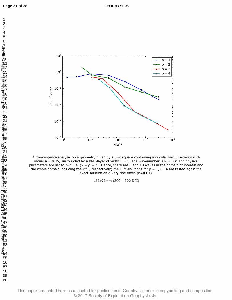
4 Convergence analysis on a geometry given by a unit square containing a circular vacuum-cavity with radius a = 0.25, surrounded by a PML-layer of width L = 1. The wavenumber is k = 10π and physical
parameters are set to two, i.e. (v = ρ = 2). Hence, there are 5 and 10 waves in the domain of interest and
the whole domain including the PML, respectively; the FEM-solutions for p = 1,2,3,4 are tested again the exact solution on a very fine mesh (h=0.01).
122x92mm (300 x 300 DPI)
Page 31 of 38 GEOPHYSICS
123456789101112131415161718192021222324252627282930313233343536373839404142434445464748495051525354555657585960
This paper presented here as accepted for publication in Geophysics prior to copyediting and composition. © 201 Society of Exploration Geophysicists.7
Dow
nloa
ded
06/1
2/17
to 1
31.1
30.1
57.1
41. R
edis
trib
utio
n su
bjec
t to
SEG
lice
nse
or c
opyr
ight
; see
Ter
ms
of U
se a
t http
://lib
rary
.seg
.org
/

5 Decrease of the scattered wavefield evaluated at the depth of 600 m on the right side of the perfectly matched layer (see red dots in the domain thumbnail).
1120x868mm (600 x 600 DPI)
Page 32 of 38GEOPHYSICS
123456789101112131415161718192021222324252627282930313233343536373839404142434445464748495051525354555657585960
This paper presented here as accepted for publication in Geophysics prior to copyediting and composition. © 201 Society of Exploration Geophysicists.7
Dow
nloa
ded
06/1
2/17
to 1
31.1
30.1
57.1
41. R
edis
trib
utio
n su
bjec
t to
SEG
lice
nse
or c
opyr
ight
; see
Ter
ms
of U
se a
t http
://lib
rary
.seg
.org
/

6 Top: Geometry of the cavity design build in Netgen. Bottom: Mesh with refinement in the cavity and the source point.
302x305mm (300 x 300 DPI)
Page 33 of 38 GEOPHYSICS
123456789101112131415161718192021222324252627282930313233343536373839404142434445464748495051525354555657585960
This paper presented here as accepted for publication in Geophysics prior to copyediting and composition. © 201 Society of Exploration Geophysicists.7
Dow
nloa
ded
06/1
2/17
to 1
31.1
30.1
57.1
41. R
edis
trib
utio
n su
bjec
t to
SEG
lice
nse
or c
opyr
ight
; see
Ter
ms
of U
se a
t http
://lib
rary
.seg
.org
/
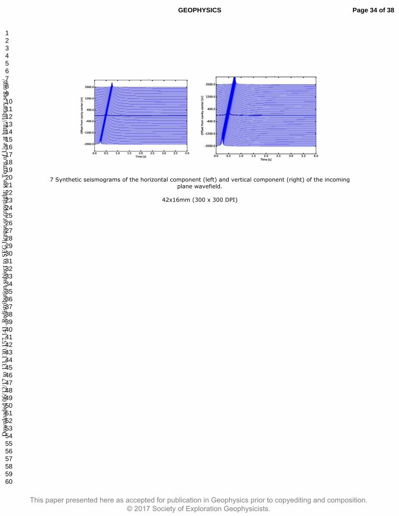
7 Synthetic seismograms of the horizontal component (left) and vertical component (right) of the incoming plane wavefield.
42x16mm (300 x 300 DPI)
Page 34 of 38GEOPHYSICS
123456789101112131415161718192021222324252627282930313233343536373839404142434445464748495051525354555657585960
This paper presented here as accepted for publication in Geophysics prior to copyediting and composition. © 201 Society of Exploration Geophysicists.7
Dow
nloa
ded
06/1
2/17
to 1
31.1
30.1
57.1
41. R
edis
trib
utio
n su
bjec
t to
SEG
lice
nse
or c
opyr
ight
; see
Ter
ms
of U
se a
t http
://lib
rary
.seg
.org
/

8 Synthetic spectrograms (left) and seismograms (right) of the vertical component of the scattered wavefield from the cavity, measured at the surface. The curve left of the spectrogram displays the spatial
distribution of the scattered field amplitude averaged over all frequencies.
142x51mm (300 x 300 DPI)
Page 35 of 38 GEOPHYSICS
123456789101112131415161718192021222324252627282930313233343536373839404142434445464748495051525354555657585960
This paper presented here as accepted for publication in Geophysics prior to copyediting and composition. © 201 Society of Exploration Geophysicists.7
Dow
nloa
ded
06/1
2/17
to 1
31.1
30.1
57.1
41. R
edis
trib
utio
n su
bjec
t to
SEG
lice
nse
or c
opyr
ight
; see
Ter
ms
of U
se a
t http
://lib
rary
.seg
.org
/
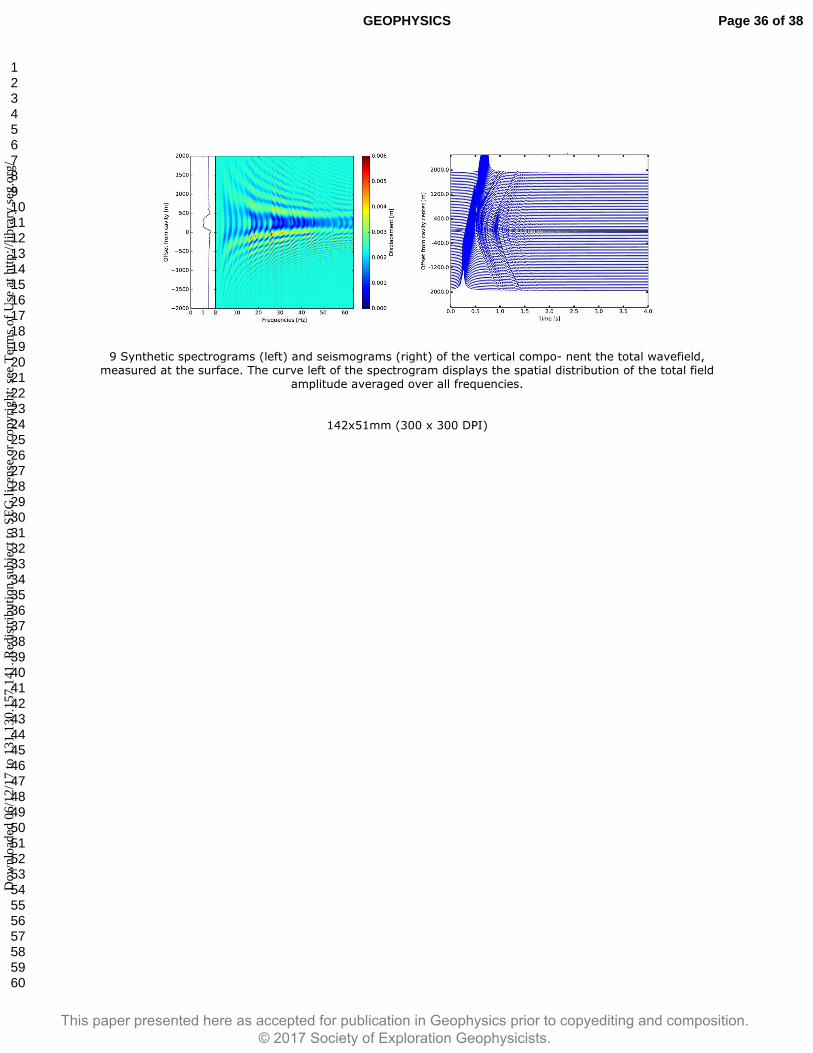
9 Synthetic spectrograms (left) and seismograms (right) of the vertical compo- nent the total wavefield, measured at the surface. The curve left of the spectrogram displays the spatial distribution of the total field
amplitude averaged over all frequencies.
142x51mm (300 x 300 DPI)
Page 36 of 38GEOPHYSICS
123456789101112131415161718192021222324252627282930313233343536373839404142434445464748495051525354555657585960
This paper presented here as accepted for publication in Geophysics prior to copyediting and composition. © 201 Society of Exploration Geophysicists.7
Dow
nloa
ded
06/1
2/17
to 1
31.1
30.1
57.1
41. R
edis
trib
utio
n su
bjec
t to
SEG
lice
nse
or c
opyr
ight
; see
Ter
ms
of U
se a
t http
://lib
rary
.seg
.org
/
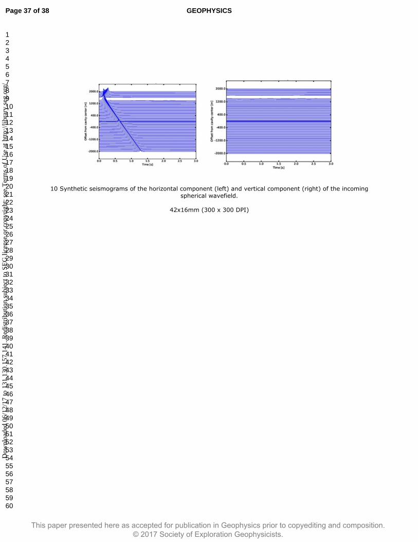
10 Synthetic seismograms of the horizontal component (left) and vertical component (right) of the incoming spherical wavefield.
42x16mm (300 x 300 DPI)
Page 37 of 38 GEOPHYSICS
123456789101112131415161718192021222324252627282930313233343536373839404142434445464748495051525354555657585960
This paper presented here as accepted for publication in Geophysics prior to copyediting and composition. © 201 Society of Exploration Geophysicists.7
Dow
nloa
ded
06/1
2/17
to 1
31.1
30.1
57.1
41. R
edis
trib
utio
n su
bjec
t to
SEG
lice
nse
or c
opyr
ight
; see
Ter
ms
of U
se a
t http
://lib
rary
.seg
.org
/
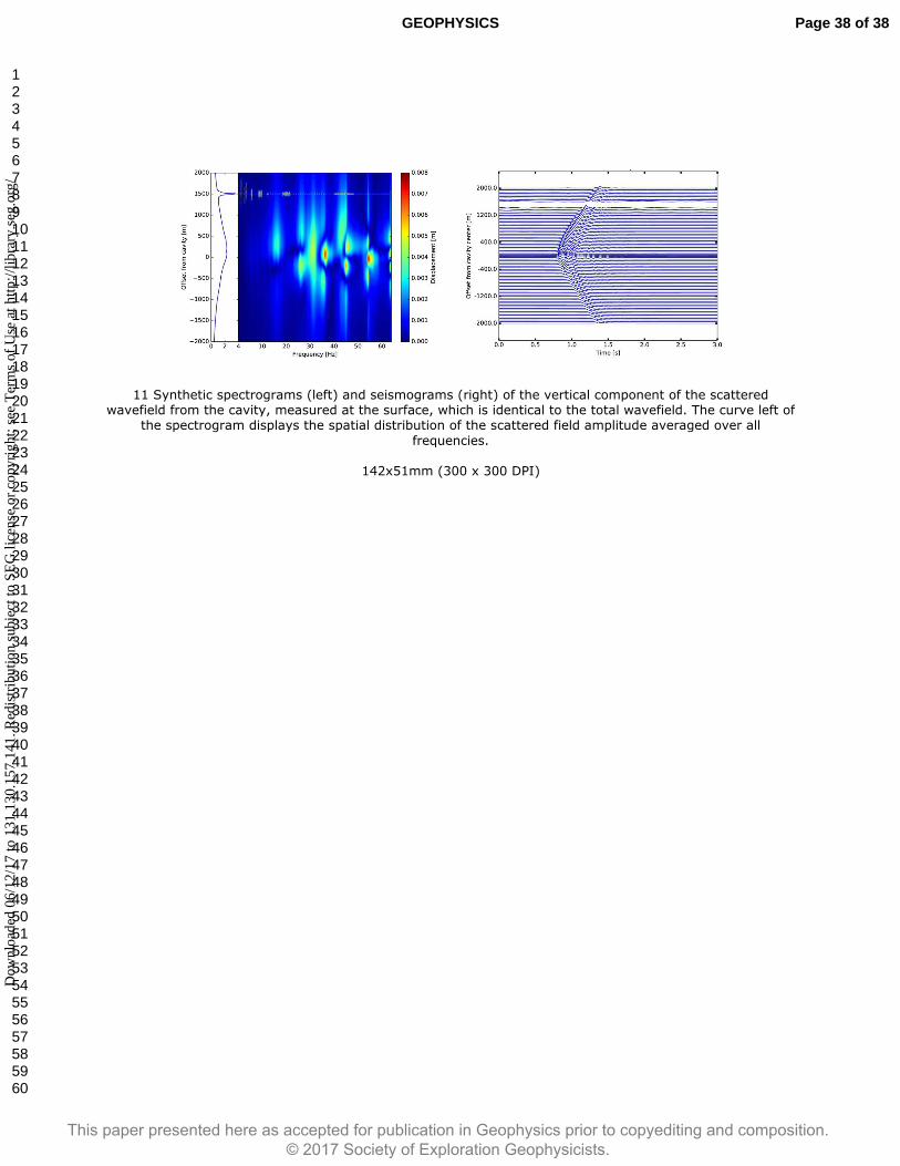
11 Synthetic spectrograms (left) and seismograms (right) of the vertical component of the scattered wavefield from the cavity, measured at the surface, which is identical to the total wavefield. The curve left of
the spectrogram displays the spatial distribution of the scattered field amplitude averaged over all
frequencies.
142x51mm (300 x 300 DPI)
Page 38 of 38GEOPHYSICS
123456789101112131415161718192021222324252627282930313233343536373839404142434445464748495051525354555657585960
This paper presented here as accepted for publication in Geophysics prior to copyediting and composition. © 201 Society of Exploration Geophysicists.7
Dow
nloa
ded
06/1
2/17
to 1
31.1
30.1
57.1
41. R
edis
trib
utio
n su
bjec
t to
SEG
lice
nse
or c
opyr
ight
; see
Ter
ms
of U
se a
t http
://lib
rary
.seg
.org
/