Embed Size (px)
Citation preview
“Application of borehole radar to pothole identification and delineation
ahead of the working face in Platinum Mines”
Authors: Dr Carina Kemp[i], Petro Du Pisani[ii] and Mduduzi Shokei
Abstract
Borehole radar is a proven geophysical technology that can be used to reduce the geological risk in extracting an ore body and therefore improve mine planning. This paper presents an example of how borehole radar can be used within the mining cycle to map out ore body blocks to assist with the mine design months ahead of mining. Refined equipment and procedures now enable a slim-line borehole radar tool to be deployed on the end of drill rods, making it easier and faster to deploy in an underground mine with minimal impact on the mining process. Slim-line borehole radar tools are deployed in applications where boreholes are drilled parallel or sub-parallel to the ore bodies in order to delineate them and any disruptive structures on them, which change the normal ore body location, thickness and sometimes composition. Advance knowledge of how the ore bodies are displaced impacts on how the ore body is mined. Mine planning can then be adapted to mine the ore body more economically, and potentially hazardous situations can be negated.
1. Introduction
Globally, the mining industry and particularly Anglo Platinum is adapting to rapidly rising labour costs and improvements in technology. It is moving from a tradition in which small, flexible airleg mining crews advance a large number of ~30m wide meter-high panels about 17m per month, through concentrated capital intensive trackless mining operations advancing at ~50m per month on a front five times wider, to experimental continuous mining operations that are projected to achieve advance rates of over 100m per month. Negotiating geological discontinuities interferes with production to a degree that generally rises with the level of mechanisation and the rate of face advance. For example, in platinum reef mining, potholes cause the most frequent disruptions. A faster advance rate increases the frequency of exposed potholes. The greater the capital concentration, the more serious the impact upon ore production. The more unexpected the pothole, the lower the stockpiles, and thus the ripple of feedstock that enters the mill is greater. Observations such as these have stimulated recent geophysical reconnaissance efforts across a number of different commodities. Three dimensional surface seismic surveys costing around AU$250 000 per square kilometre can map faults of several meters of throw, and most shallow potholes greater than 50m wide in plan on those parts of platinum reef that are neither overshadowed by old workings on an overlying platinum reef, nor vulnerable to screening by seismic reverberation between horizons that lie either above or near the platinum reef. This technique is useful on a broader exploration scale, but more detailed information is needed to negotiate geological discontinuities on the panel scale. The work described in this paper shows how mining operations can be supported by tactical underground borehole radar (BHR) surveys, and puts forward the proposition that BHR can be used to better manage many of the risks that are inherent in concentrating production on a small number of high output mechanised panels. 2. Borehole Radar for Platinum Mining
BHR is an electromagnetic subsurface imaging technique designed for imaging or detecting discontinuities in restive hard rock formations. Radar works best when the tool is deployed in a resistive host rock and used to image a conductive ore body. Reflections are normally caused by sharp changes in the electrical properties of the rock, and can yield information on geological change, faults/fractures, voids, dykes, ore body geometry, etc. On the other hand, conductive or highly fractured rock formations increase the attenuation (scattering) of electromagnetic energy, making BHR less effective. 2.1 Instrumentation
A BHR tool consists of a transmitter and receiver, which can be combined in one antenna, resulting in a “single-stick” probe, or as two separate antennas in two separate probes, usually separated by a fibre optic spacer. Both antenna configurations have their advantages and disadvantages, however due to logistical and space constraints in underground hard rock mining, usually the “single-stick” probes are used. The slim-line BHR tool has been designed specifically for underground mining. Its diameter enables it to fit into exploratory geological or cover drill holes with diameters smaller than 48mm. The BHR tool is broadband, with a centre frequency of 50MHz. This equates to a range in most hard-rock environments of at least 30m from the borehole, but up to 80m in some rock types. The dielectric properties of the host-rock determine the range that BHR can achieve. Slim-line BHR tools are omni-directional. Reflection data is recorded from signals received from 360 degrees surrounding the boreholes. While a lot of research is being conducted in directional radar technology, it is difficult to fit an efficient directional radar antenna in a probe that will fit in underground mining drill holes, e.g less than 48mm diameter. 2.2 Deployment Methods
The current BHR design has come a long way in the last couple of years. Improving from probes that were connected by fibre optics to a digital acquisition system at the borehole collar (Vogt, 2006), to the single-stick radars with onboard memory (Bray et al, 2007) enabling surveying to be conducted on the drill rods directly after the boreholes are drilled, in the same manner that borehole deviation surveys are conducted. The latter technique now enables BHR to be surveyed in all underground boreholes, where previously broken ground and difficult end of hole pulley deployment methods hindered its success.
2.3 Borehole Radar Survey Design
The borehole design and layout is absolutely critical in successful radar implementation. For thin reef or vein style deposits, BHR is generally conducted in a series of regularly spaced single-borehole reflection surveys, however, the borehole design depends greatly on the type of ore body and the geological discontinuities associated with it. Here we will look at a BHR survey design for thin reef or vein style deposits. Survey design is conditioned by limitations of site access and possible parallel layering due to bedding or joint planes within the host rock. Consider, in Figure 1a, the descent of a BHR through a succession of bedding planes, the UG2 (Hangingwall bedding) and UG1

(Footwall bedding). Passage of the borehole past each plane in turn can be traced in the synthetic radargram (Figure 1b). The curved borehole produces curved reflections in the radargram. An inclined and curved borehole enables one to interpret whether a reflector lies above or below the borehole overcoming the non-directional nature of the borehole radar antenna.
Figure 1: (a) example borehole radar layout, (b) resulting borehole radar radargram.

3 Example of borehole radar for Platinum Mining
3.1 Overview
BHR has been used successfully in many of South Africa’s underground platinum mines to delineate both the Merensky and UG2 platinum reefs (Van Schoor et al, 2006; De Vries and Du Pisani, 2007). Here we will consider potholes and rolls that disrupt the reef. According to Lomberg et al (1999), potholes are more disruptive to layering and mining than rolls. Mining operations near potholes are disrupted by the sudden dip in the strata, increasing the number of joints and talc-filled fractures, cross cutting pegmatite veins and a weakening of the roof. The reef thins gradually on approach to a shallow conformable pothole. More rapid reef thinning indicates an approach to a deep unconformable pothole. “At the edge the upper leader chromitite suddenly breaks through the lower leader chromitite layers and then, over 2-5m, cuts sharply into the underlying feldspathic pyroxenite … sometimes … so sharply that it cuts back underneath the pothole reef” (after Lomberg et al 1999). Potholes range from 1 to 500m in diameter, drop from 1-100m into the footwall, and can have sloping, steep, or even overhanging margins. They can appear as simple washouts, as slumps, or as deeply sunken cones, the sides of which may be decorated by shards of UG2 chromitite, and into which are sucked substantial amounts of the hanging wall. The layers above a deep pothole are frequently deformed, sometimes plastically. Brittle failures above some potholes fault the hanging wall and hamper efforts to mine into or through them.
3.2 Borehole Radar Survey Design
BHR test surveys were conducted in 2003 at Anglo Platinum’s Bleskop shaft that is close to Rustenburg (South Africa) in order to detect disruptions in the UG2 reef, demonstrate that BHR can be used to optimise mine layouts and to test the viability of applying BHR in underground platinum mines. The locations of boreholes drilled for the application of BHR are limited by the access available from mining excavations. Platinum reefs in South Africa are traditionally mined using a conventional breast stoping mining method. Radar boreholes are usually drilled below the reef in the footwall, either from haulages or crosscuts, and are oriented parallel or sub-parallel to the reef plane. This enables the radar to image back up onto the UG2 as shown in Figure 2. The area covered by radar boreholes is usually the size of a planned stope, around 200 x 200m. This enables mapping the reef topography prior to mining. Figure 3 illustrates how a mining panel can be scattered with pothole and rolls that have been missed by exploration and resource definition drilling. Figure 3b shows a panel which neighbours our example survey area where more than 30% of the panel was corrupted by disturbed ground. Using a borehole layout as shown in Figure 3c the entire panel can be mapped with borehole radar produced a contour map similar to that shown in Figure 3d. A similar survey design was used in the borehole radar example shown here.

Figure 2. Boreholes drilled from below the prospective reef horizon (e.g. the UG2) provide coverage of the reef panel with borehole radar.
Figure 3: A mining panel can be scattered with potholes and rolls that have been missed in resource definition drilling as shown as a schematic in (a) and from a real mining layout in (b). Four boreholes drilled from development (c) can provide enough coverage for a detailed reef contour (d) to prevent unexpected hazards in mining.
3.3 Borehole Radar Results and Interpretation
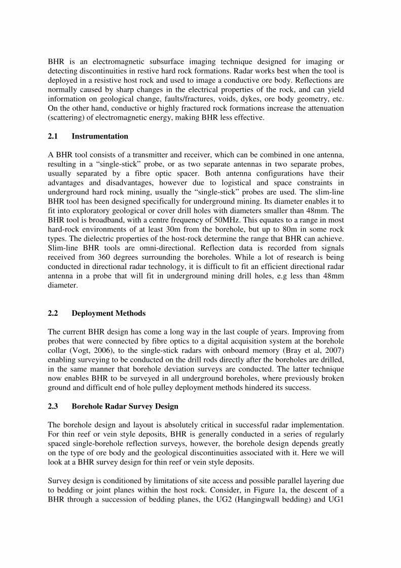
The five panels in Figure 4 show the radargrams from an example panel, shown in the top right of Figure 4, in the Bleskop Platinum Mine. It is difficult to identify the different reflections in the data from the borehole radar data alone. This is difficult because slimline BHRs have toroidal non-directional radiation patterns and therefore collect data from 360 degrees around the drillhole. Distinguishing between arrivals from planes above the borehole and from those below is accomplished by modelling the curvature of the borehole with the expected reef planes, similar to what was shown above in Figure 1. The radargram for BH1 contains the expected reef reflections for the UG1 and UG2 as dashed white lines. Using these lines as a guide you can easily trace the reflections from the UG1 and UG2 in the remaining radargrams.
Figure 4. Example borehole radargrams from a layout of five boreholes across a mining panel, plan shown top right. Radargrams are filtered and gain-swept. Time runs vertically downwards. Distance from hole collars runs horizontally across the radargrams. The radargram for BH1 (top left) shows the expected curved radar reflections from the UG1 and UG2. These reflections follow a similar shape to the synthetic section shown in Figure 1(b) and can be easily seen across the remaining radargrams. Deviations from the smooth curves indicate undulations on the reef horizons.
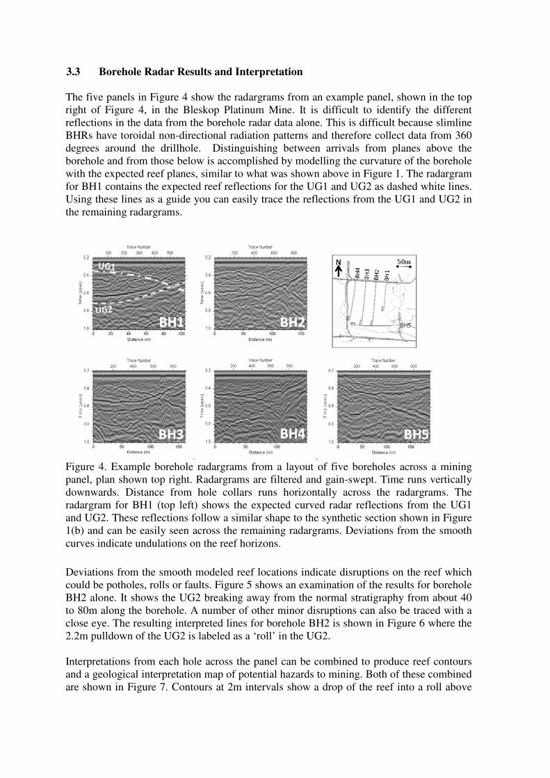
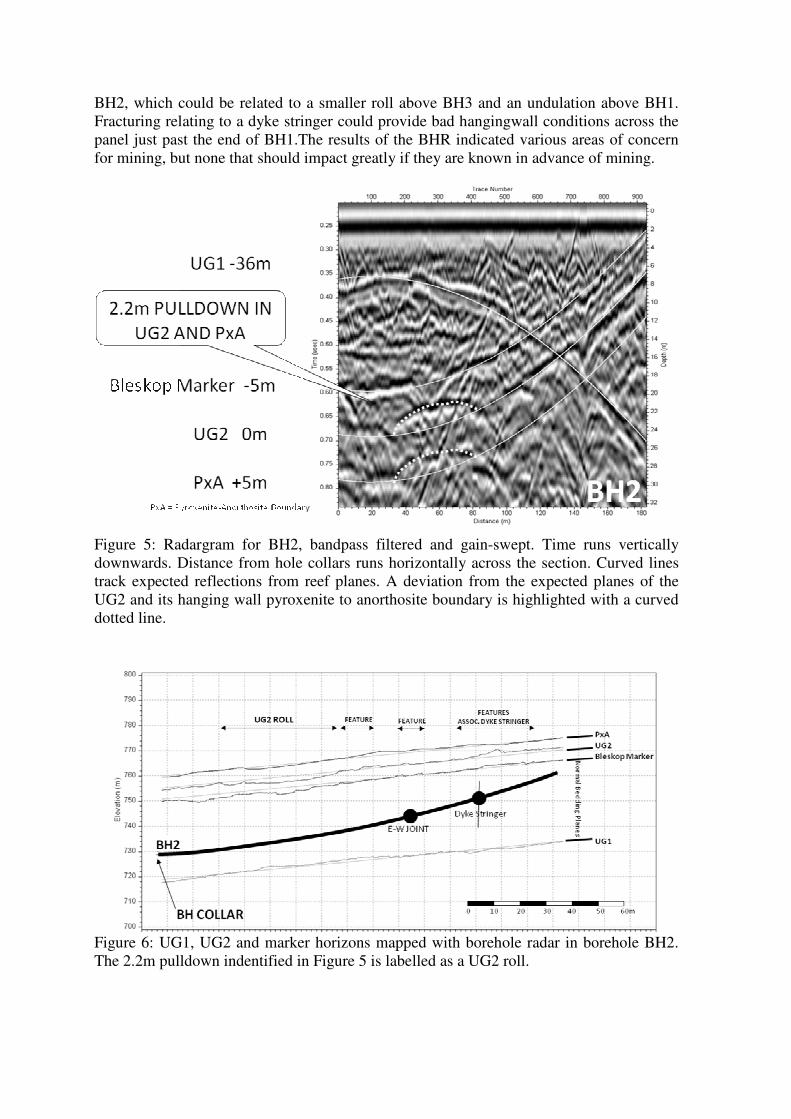
Deviations from the smooth modeled reef locations indicate disruptions on the reef which could be potholes, rolls or faults. Figure 5 shows an examination of the results for borehole BH2 alone. It shows the UG2 breaking away from the normal stratigraphy from about 40 to 80m along the borehole. A number of other minor disruptions can also be traced with a close eye. The resulting interpreted lines for borehole BH2 is shown in Figure 6 where the 2.2m pulldown of the UG2 is labeled as a ‘roll’ in the UG2. Interpretations from each hole across the panel can be combined to produce reef contours and a geological interpretation map of potential hazards to mining. Both of these combined are shown in Figure 7. Contours at 2m intervals show a drop of the reef into a roll above
BH2, which could be related to a smaller roll above BH3 and an undulation above BH1. Fracturing relating to a dyke stringer could provide bad hangingwall conditions across the panel just past the end of BH1.The results of the BHR indicated various areas of concern for mining, but none that should impact greatly if they are known in advance of mining.
Figure 5: Radargram for BH2, bandpass filtered and gain-swept. Time runs vertically downwards. Distance from hole collars runs horizontally across the section. Curved lines track expected reflections from reef planes. A deviation from the expected planes of the UG2 and its hanging wall pyroxenite to anorthosite boundary is highlighted with a curved dotted line.
Figure 6: UG1, UG2 and marker horizons mapped with borehole radar in borehole BH2. The 2.2m pulldown indentified in Figure 5 is labelled as a UG2 roll.
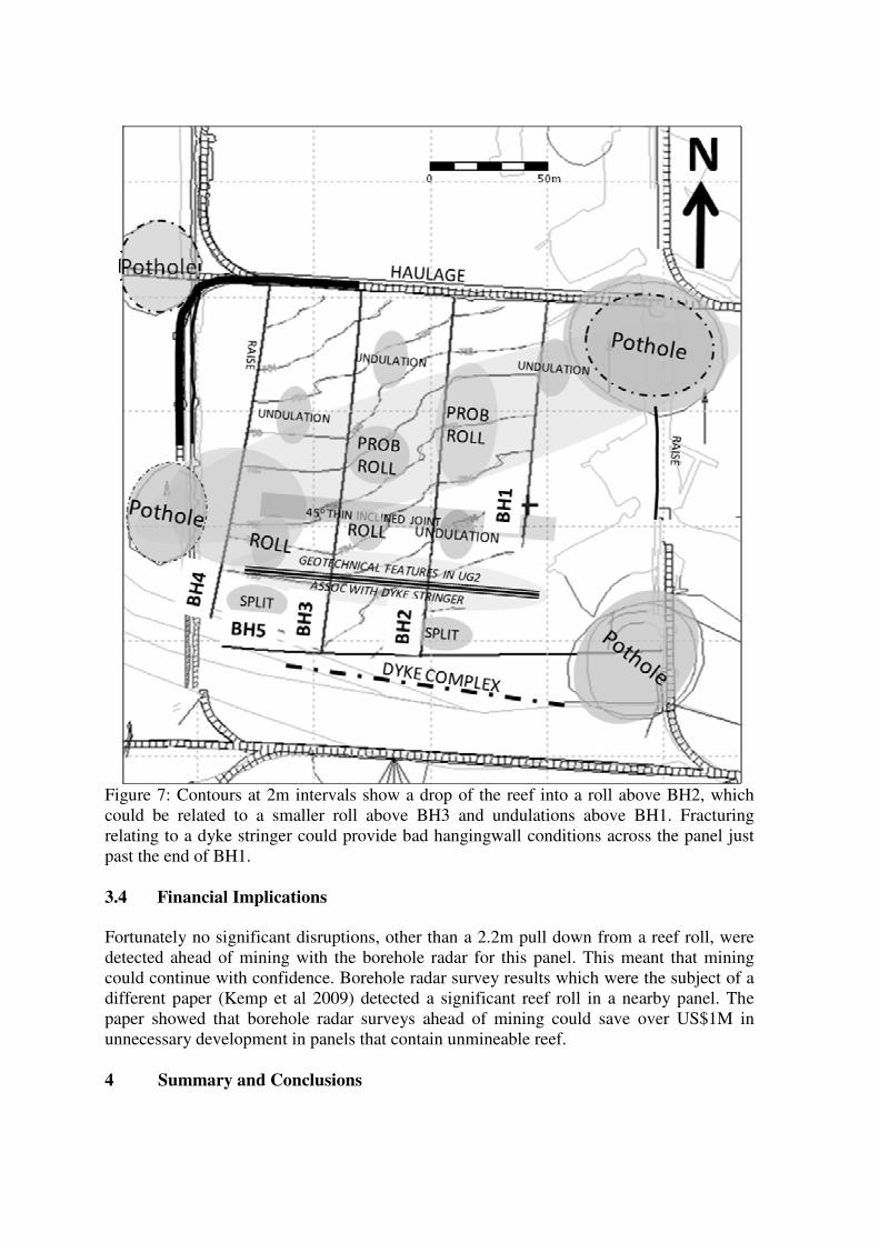
Figure 7: Contours at 2m intervals show a drop of the reef into a roll above BH2, which could be related to a smaller roll above BH3 and undulations above BH1. Fracturing relating to a dyke stringer could provide bad hangingwall conditions across the panel just past the end of BH1. 3.4 Financial Implications
Fortunately no significant disruptions, other than a 2.2m pull down from a reef roll, were detected ahead of mining with the borehole radar for this panel. This meant that mining could continue with confidence. Borehole radar survey results which were the subject of a different paper (Kemp et al 2009) detected a significant reef roll in a nearby panel. The paper showed that borehole radar surveys ahead of mining could save over US$1M in unnecessary development in panels that contain unmineable reef. 4 Summary and Conclusions

This paper has presented an introduction to BHR and how it can be used in Platinum Mining. In the example shown borehole radar was used to map the UG2 reef and disruptions on the reef ahead of mining. If applied correctly this can significantly contribute to lowering the costs of operating a platinum mine. Strategically conducting BHR surveys both prior to and within the mining cycle improves the geological knowledge about the ore body. BHR surveys enable strategic mine planning for the appropriate mine design, and the efficient deployment of mining teams. But most of all, BHR can identify additional resources in structurally complex areas of the mine and sterilise areas that are too disrupted to mine. At Anglo Platinum, BHR has since moved beyond the realm of trial surveys and is being routinely applied as a geological mapping tool at various mines. 5 Acknowledgments
The authors thank Anglo Platinum for allowing these results to be published. In particular, all the Rustenburg geologists, borehole radar surveyors and drilling contractors who have made these borehole radar surveys possible. The authors would like to acknowledge staff members and miners of Anglo Platinum for their vision and support of the implementation of geophysical programms. The professional enthusiasm of Anglo Platinum staff made this study both possible and enjoyable. We thank the drillers of Rosond, and all of the miners for their competence and invariably kind assistance. The authors gratefully acknowledge the scientific and technical contributions of the CRCMining, University of Sydney and University of Stellenbosch Borehole Radar research Teams.
6 References
Bray, A., Sindle, T., Mason, I.M., Palmer, K., Cloete, J., Steenkamp, J., Du Pisani, P. & Trofimczyk, K. Using slimline borehole radar from cover holes. Tenth SAGA Biennial
Technical Meeting and Exhibition, Wild Coast Sun, 2007.
Cawthorn, R. G., The platinum and palladium resources of the Bushveld Complex, South
African Journal of Science, 1999. Vol. 95, pp. 481-489.
Davis, J.C., Statistics and data analysis in geology. John Wiley: New York 2nd Edition, 1986. p. 290.
De Vries, P. & Du Pisani, P. Borehole radar delineation of the UG2 reef at Modikwa Mine, The Ninth SAGA Biennial Technical Meeting and Exhibition, 2005.
Du Pisani, P., Mason, I.M. & Daniso, L.N., Borehole radar delineation of the Brakspruit regional pothole at Anglo Platinum’s Rustenburg Section, Tenth SAGA Biennial Technical
Meeting and Exhibition, Wild Coast Sun. 2007.
Du Pisani, P., Coomber, S., Chitiyo, G., Daniso, V., Mampa, S. & Mason, I., Using borehole radar to detect disruptions in platinum reefs in South Africa – the financial

implication, 12th
International Conference on Ground Penetrating Radar, Birmingham,
UK, 2008.
Eales, H.V., Botha, W.J., Hattingh, P.J., De Klerk, W.J., Maier, W.D. & Odgers, A.T.R., The mafic rocks of the Bushveld Complex: a review of emplacement and crystallization history, and mineralization, in light of recent data, Journal of African Earth Science, 1993. Vol. 16, pp. 121 – 142.
Kemp, C., Du Pisani, P., Bray, A., and Chitiyo, G. Reducing the Geological Risk in Mining an Orebody by Using Borehole Radar for Strategic Mine Planning, Orebody
Modelling and Strategic Mine Planning, Perth, WA, 2009.
Lomberg, K.G., Martin, E.S., Patterson, M.A. & Venter, J.E., The morphology of potholes in the UG2 Chromitite Layer and Merensky Reef (pothole reef facies) at Union Section, Rustenburg Platinum Mines, South African Journal of Geology, 1999. Vol. 102, no. 3, pp. 209-220.
Van Schoor, M., Du Pisani, P. & Vogt, D. High-resolution, short-range, in-mine geophysical techniques for the delineation of South African ore bodies South African
Journal of Science, 2006. Vol. 102, pp. 355 – 360.
Viljoen, M.J. & Schürmann, L.W., The Mineral Resources of South Africa. Council for Geoscience, South Africa, Pretoria. 1998.
Vogt, D. A borehole radar system for South African gold and platinum mines, South
African Journal of Geology, 2006. Vol. 109 pp. 521 – 528.
[i]
Geomole Pty Ltd
Suite 108, 2 Cornwallis St
Eveleigh, NSW 2015
Australia
Ph: +61 2 9209 4191
[ii] Geosciences Resource Group
Anglo Technical Division
PO Box 61587
Marshalltown, 2107
South Africa