Embed Size (px)
Citation preview

Application of alteration minerals and thermal fluid geochemistry in
geothermal conceptual modeling, case study of Olkaria geothermal
field in Kenya
M1BEI GEOFFREY KIPTOO
156/78011/2009
A dissertation submitted in partial fulfillment of the requirements for the degree of Master of Science in Applied Geochemistry
4 >
APRIL, 2012

DECLARATION
I hereby declare that this dissertation is my original work and has not been presented for a degree
in any other university or any other award.
Signature J _________ Date: n ,
Mr. Geoffrey Kiptoo Mibei
University of Nairobi
School of Physical Sciences
Department of Geology
We hereby confirm that Mr. Geoffrey Kiptoo Mibei is candidate under our supervision
undertaking the work reported in this dissertation;
Signature______
Dr. Daniel Olago
University of Nairobi
School of Physical Sciences
Department of Geology
Signature
Dr. Christopher Nyam;
University of Nairobi
School of Physical Sciences
Department of Geology
Date: f ! «/
II

ABSTRACT
The Olkaria geothermal field is located within the central sector of the Kenyan Rift Valley in
Naivasha basin. It is a high-temperature geothermal system and is associated with late
Quaternary rhyolite volcanism. The surface geology of Olkaria is mainly characterized by
comendite lavas, trachyte lavas and pyroclastics while low lying areas are mainly masked by
Holocene sediments especially in the Ol'Njorowa Gorge. Shallow rhyolitic intrusions are thought
to be the heat source for the geothermal system. This study considers geothermal conceptual
modeling as an important tool in exploration and exploitation of geothermal resources. The main
objective is to use thermal fluids and hydrothermal alteration mineral geothermometry to develop
a conceptual model of the Olkaria geothermal field. Hydrothermal alteration mineralogy and
thermal fluid chemistry are important sources of useful information in geothermal conceptual
modeling. Alteration minerals can be used to infer subsurface formation temperatures and also
reconstruct the thermal history of a geothermal field. Chemical and solute geothermometers
from thermal fluid analysis on the other hand help in the calculation of subsurface temperatures.
The approach pursued in the study included; (1) The chemical analysis of major elements in the
thermal fluids from Olkaria Northeast, Olkaria East and Olkaria Domes subfields, in order to
calculate subsurface temperatures using geothermometric equations by Fournier (1979),
Amosson et al. (1983) and Giggenbach (1988). (2) The use of lithological logs from wells OW-
710, OW-23 and OW-910A drilled in the aforementioned subfields to reconstruct
lithostratigraphy and hydrothermal alteration zonation. The key index minerals are identified and
temperature isotherms mapped. The temperature results from thermal fluids and alteration
minerals are analyzed and correlated to identify the inflow, upflow and the outflow. The data is
analyzed with the help of high definition softwares such as Rockworks, Surfer and ArcGlS. In
this study, minerals such as epidote and actinolite are identified, they infer temperatures of
>250°C and 280°C respectively and are markers for an upflow zone in the system. Results from
calculated temperature on fluid chemistry and inferred temperatures from alteration minerals,
indicate an anomalously relatively high subsurface temperature in Olkaria Northeast compared to
Olkaria East and Olkaria Domes. This indicates that the Northeast field is one of the upflow
zones for the Olkaria geothermal system.
iii

ACKNOWLEDGEMENT
This study was made possible with the assistance of a number of selfless individuals and
organizations. 1 deeply appreciate the assistance and continued guidance I have received from
my supervisors. Dr. D. Olago and Dr. C. Nyamai. Dr. Olago relentlessly guided me during the
proposal writing, data setup and synthesis and the write-up of the dissertation. Dr. Nyamai
patiently supplied me with fruitful criticisms and much-needed inputs that added value to the
study. I also appreciate the focused contribution from Dr. Kuria (of University of Nairobi), Mr.
John Lagat, Paul Odhiambo and Irene Mboin (of Geothermal Development Company) touching
on specific areas of this dissertation especially the field planning. To the Kenya Electricity
Generating Company (KENGEN) for the help they provided in carrying out field mapping,
sample analysis and provision of other relevant data.
1 am grateful to the administration of the University of Nairobi for the scholarship they offered
me for my MSc. studies. I acknowledge the support and guidance from the entire administration
and staff of Geology department under the chairmanship of Dr. C. Nyamai. 1 specifically express
my gratitude to both the teaching staff and technical team in the department for their selfless
services. To my colleagues, thank you for your encouragement, helpfiil data and information you
provided for my dissertation. To my family, you gave me the motivation and love that 1 badly
needed during this time. And above all, to God who enabled me to accomplish this hectic though
worthy course in sound health.
IV

TABLE OF CONTENTS
DECLARATION.................................................................................................................................ii
ABSTRACT........................................................................................................................................ iii
ACKNOWLEDGEMENT.................................................................................................................. iv
TABLE OF CONTENTS.....................................................................................................................v
CHAPTER O N E................................................................................................................................ 1
1.0 INTRODUCTION...................................................................................................................... 1
1.1 Background information............................................................................................................1
1.2 Statement of problem................................................................................................................ 3
1.3 Objectives................................................................................................................................... 3
1.3.1 Main objective.....................................................................................................................3
1.3.2 Specific objectives.............................................................................................................. 3
1.4 Justification and significance....................................................................................................4
1.5 Literature review........................................................................................................................4
1.5.1 Lithology..................................................................................................'......................... 4
1.5.2 Hydrothermal alteration minerals.......................................................................................5
1.5.3 Thermal fluid geochemistry........................................................................................ 8
CHAPTER TW O ............................................................................................................................. 11
2.0 THE STUDY AREA................................................................................................................ 11
2.1 General information..................................................................................................... ..........11
2.2 Physiography and drainage..................................................................................................... 12
2.3 Geological setting..................................................................................................................... 13
2.3.1 Regional geology................................................... .'.......................................................13
v

2.3.2 Local geology....................................................................................................................15
2.3.3 Structural geology and tectonics.......................................................................................17
2.4 Hydrogeology........................................................................................................................... 19
CHAPTER THREE.........................................................................................................................21
3.0 METHODOLOGY.................................................................................................................. 21
3.1 Data sourcing and handling.....................................................................................................22
3.2 Data interpretation....................................................................................................................22
3.3 Field w ork......... ......................................................................................................................22
3.3 Laboratory methods................................................................................................................. 24
3.3.1 Stereo microscope analysis...............................................................................................24
3.3.2 X-ray diffractometer analysis.......................................................................................... 24
3.3.3 Petrographic microscope analysis................................................................................... 24
CHAPTER FOUR............................................................................................................................25
4.0 RESULTS.................................................................................................................................25
4.1 Surface geology of Olkaria......................................................................................................25
4.2 Lithology..................................................................................................................................28/
4.3 Stratigraphic correlation.......................................................................................................... 32
4.4 Petrochemistry of Olkaria field rocks..................................................................................... 34
4.5 Description and distribution of hydrothermal alteration minerals............................... !?..... 37
4.6 Hydrothermal zonation............................................................................................................ 44
4.7 Fluid geochemistry of the Olkaria fields............................................................................... 46
4.8 Solute geothermometry.................................................................................. .............T........47
CHAPTER FIVE.............................................................................................................................49
5.0 DATA SYNTHESIS AND THE CONCEPTUAL MODELLING.......................................49
5.1 Geology and petrochemistry................................... ..............................-................................49
VI
5.1.1 Surface geology of Olkaria............................................................................................. 49
5.1.2 Lithostratigraphy.............................................................................................................. 50
5.1.3 Petrochemistry.................................................................................................................. 50
5.2 Fluid geochemistry and geothermometry..............................................................................51
5.3 Hydrothermal alteration and zonation................................................................................... 52
5.4 Conceptual model.....................................................................................................................53
CHAPTER SIX................................................................................................................................ 57
6. 0 CONCLUSION AND RECOMMENDATIONS................................................................. 57
6.1 Conclusion................................................................................................................................57
6.2 Recommendations.................................................................................................................... 58
REFERENCES................................................................................................................................. 58
APPENDIX IA: Preparation of samples for clay analysis.......................................................... 63
APPENDIX IB: A flow chart on procedure for XRD analysis................................................... 64
APPENDIX II: Well log of OW-912A based on binocular microscope analysis...................... 65
APPENDIX III: Clay analysis and interpretation.........................................................................78/
\
/i
vii
/

Figure 1.1: Georeferenced Olkaria subfields in UTM coordinates..............................................1
Figure 1.2: CI-SO4-HCO3 Ternary diagram.................................................................................. 9
Figure 2.1: Map of the study area................................................................................................ 11
Figure 2.2: Physiography of around Olkaria geothermal field...................................................12
Figure 2.3 : The Great Rift Valley system...................................................................................14
Figure 2.4: Quaternary volcanic centers..................................................................................... 16
Figure 2.5: Olkaria ring structure................................................................................................18
Figure 2.6: Regional hydrogeological map.................................................................................19
Figure 3.1: A flowchart the five primary stages in the study.....................................................21
Figure 3.2: Location of study wells..............................................................................................23
Figure 4.1: The geological map of Olkaria area..........................................................................23
Figure 4.2: Lithology and hydrothermal alteration minerals in well OW-710.......................... 29
Figure 4.3: Lithology and hydrothermal alteration minerals in well OW-912A.......................30
Figure 4.4: Lithology and hydrothermal alteration minerals in well OW-23............................ 31
Figure 4.5: Geological cross-section between well OW-912A,OW-23 and OW-710............... 33
Figure 4.6: TAS Classification based on the petrochemical results............................................ 36
Figure 4.7: Classification in terms of Al2OHotal iron as FeO diagram...................................... 37
Figure 4.8: Diffractogram showing calcite peaks............................................................... 37
Figure 4.9: Vescicle filling chlorite in thin section.................................. 39
Figure 4.10: Diffractograms showing chlorite peaks................................................................ 40
Figure 4.11: Diffractograms showing illite peaks...............................................:...........4,...... 42
Figure 4.12: Diffractogram showing pyrite peaks.................................................................... 43
Figure 4.13: Distribution of hydrothermal across wells OW-912A, OW-23 and OW-710....45
Figure 4.14: Average chloride concentration from Olkaria fields............. '............................... 461
LIST OF FIGURES
viii

Figure 4.15: Temperatures inferred from the K/Na ratios...........................................................47
Figure 4.16: Temperatures inferred from the quartz geothermometry........................................48
Figure 5.1: Cross-section line (A, B, C, and D)..........................................................................54
Figure 5.2: Integrated conceptual geothermal model............................................................... 55
Figure 5.3: A three dimensional conceptual model of Olkaria geothermal field.................... 56
LIST OF TABLES
Table 1.1: Location of wells OW- 23,OW-710 and OW-912A...................................................2
Table 1.2: Common alteration minerals with their equilibrium temperatures............................. 6
Table 1.3: Common hydrothermal alteration minerals and temperature stability ranges...........7
Table 1.4: Primary minerals and their altered equivalents........................................................... 8
Table 4.1: Petrochemistry of Olkaria Northeast and East fields................................................ 34
Table 4.2: Chemistry of Olkaria domes.......................................................................................35
Table 5.1: Hydrothermal alteration mineral in the study wells..................................................52
/
IX

CHAPTER ONE
1.0 INTRODUCTION
1.1 Background information
The Olkaria Geothermal field is a high-temperature geothermal system located within the central
sector of the Kenyan Rift Valley in Naivasha basin. It is associated with late Quaternary
rhyolite volcanism (Omenda 1998).The study area has been divided into seven sub fields these
are; Olkaria East, Olkaria Central, Olkaria Northeast, Olkaria West, Olkaria Southwest, Olkaria
South, and Olkaria Domes (Figure 1.1).
O L K A R IA S U B F IE L D S
o
M eters0 2,200L__________ I
Figure 1.1: Georeferenced Olkaria subfield in UTM coordinates (after Muchemi 2000)
1

Geothermal resources in this area have been developed since the 1980s.The current installed
capacity of about 200 megawatts of electricity and over 110 wells drilled for production and re
injection purposes. Being a high enthalpy geothermal resource with a potential of generating
much more steam for electric generation, the current status is far from its full potential. There is
therefore a need to invest in drilling of productive wells and increase the electric output. Good
production wells can only be achieved by targeting productive areas using an accurately
developed model indicating upflow, outflow zones and recharge areas.
This study has helped in understanding the field better and in deriving an accurate model. It
describes thermal fluids and hydrothermal alteration minerals geothermometry from Olkaria
East, Olkaria Northeast and Olkaria Domes fields. According to Sarolkar (2000), the prominent
hydrothermal minerals in geothermal systems are; stilbite, quartz, limonite, smectite, albite with
subordinate illite and calcite. Most of these minerals are encountered in Olkaria as hydrothermal
alteration minerals. Colin and Patrick (2000) indicated that the success of the application of
hydrothermal minerals in geothermometry largely depends on the permeability and ability to
achieve equilibrium between fluids and host rocks. Therefore this study is based on this
assumption.
The approach of the study is to use data from previous work on well (OW-23) located in Olkaria
East and well (OW-710) in Northeast field. Analysis of sample cuttings from well (OW- 9I2A)✓
in Olkaria Domes using X-Ray diffraction and petrographic methods will also be carried out.
The coordinate location in UTM of the mentioned wells are as shown in (Table 1.1) below.
Table 1.1: Location of wells OW- 23, OW-710 and OW-912A (Units in meters)
Well No. Northing! M) Easting (M) Elevations (M) Depth (M)
912A 9898199 204633 2074 300Q
23 9901677 201308 1940 1292
710 9904490 198268 2069 . 1801
2

Being an energy deficit country and need to mitigate on the anthropogenic influences on climate
change, the Kenya government has opted for geothermal as the best alternative source of energy.
Geothermal energy is clean, reliable and independent of erratic climatic patterns. Due to this
renewed vigor in geothermal development, drilling of production wells in Olkaria geothermal
field is being undertaken by Geothermal Development Company (GDC) under the Ministry of
Energy. This study will, therefore be a guide to priority areas for production and possible areas
where reinjection wells being drilled by GDC and move closer to realizing the full potential of
the Olkaria field.
1.2 Statement of problem
Geothermal resource development has always relied on conceptual modeling and simulations as
an approach to understanding a geothermal system comprehensively. Models are imperative in
developing strategies of how to efficiently exploit geothermal resources. Alteration minerals and
fluid geochemistry can be employed as temperature proxies and consequently guide in pointing
out the best drilling targets by indicating possible upflow and outflow zones, recharge areas, as
well as permeable zones. A successful study was done in Olkaria Domes (Lagat 2004) using
alteration minerals; however, there is need to apply both thermal fluids and alteration mineral
characteristics and interaction on a larger scale in various fields. In this regard the study has
applied alteration minerals and fluid geochemistry (i.e. chemical geothermometiy). This will not
only help in developing an integrated geothermal conceptual model of the Olkaria field, but also
test the validity and applicability of thermal fluids as temperature proxies.
1.3 Objectives
1.3.1 Main objective
The main objective is to use thermal fluids and hydrothermal alteration mineral geotliermometry
to develop a conceptual model of the Olkaria geothermal field.
1-3,2 Specific objectives4',
• Review geology and petrochemistry data of Olkaria geothennal system and relate
geological logs from selected wells so as to develop a lithostratigraphic correlation of the area;
3

• Review fluid chemistry data with respect to solute and chemical geothermometers in
order to calculate subsurface temperatures in the field;
• Identify hydrothermal alteration minerals and temperature zonation from sample cuttings
in order to infer the subsurface temperatures in each well; and
• Develop a conceptual geothermal model.
1.4 Justification and significance
A conceptual model of Olkaria Domes was developed based on alteration minerals from wells
OW-901, OW-902 and OW-903 (Lagat 2004). The model was very instrumental in
understanding temperature zonation and locating high value targets in Olkaria Domes area for
drilling. The Olkaria geothermal system is, however, large and complex hence understanding it
in a detailed manner is important, particularly now when appraisal and production drilling is
being scaled up in Olkaria Northeast and East fields which are remote from the better understood
Olkaria Domes. This study is of great significance in that it will assess three wells in Olkaria
North East, Olkaria East and Domes area by applying alteration mineral characteristics in
addition to fluid chemistry data. The results will give more detail information on subsurface
temperatures hence elucidating the upflow, outflow and permeable zones in the Olkaria
subfields. The ultimate goal is to developing a conceptual model of the three Olkaria sub fields,
which will greatly enhance the understanding of the geothermal system. The study will also help
validate thermal fluids as proxies in geothermal modeling. The model will be used as a tool for
the current and future designs for sustainable exploitation of the resource.
1.5 Literature review
1.5.1 Lithology
Studies by Thomson and Dodson (1963) showed that the surface geology of Olkaria volcanic
complex is dominated by pyroclastics which blanket all the other rocks. These pyroclastics were
found to be of Quaternary age mainly from Longonot and other small eruption centers within
Olkaria. Other lithologic units like the comendites are found in the central parts of Olkaria.
Omenda (1998), Muchemi (2000) and Lagat (2004) working in Olkaria on 90 wells that had been
drilled in the field found out that the lithostratigraphic units encountered include pyroclastics,
4

tuffs rhyolites, trachyte, phonolites, basalts and minor intrusives. Studies by Lagat (2004)
mainly focusing on Olkaria Domes field showed that from the surface to about 400 m below the
surface the predominant lithological units were the pyroclastics. The major lithological units
below 400 m were trachyte, basalts with rhyolites and tuffs occurring as intercalations.
1.5.2 Hydrothermal alteration minerals
Extensive research and studies by Browne (1978) and Utami et a/. (2005) have been done on
Olkaria and Indonesian geothermal systems. The results indicated that the chemical composition
of host rocks and possible fugitive components from presumed magmatic heat sources
determines the availability of components to form hydrothermal alteration minerals. The most
critical factor, however, for hydrothermal alteration is temperature because most mineral
components are unstable at elevated temperature.
Pressures at depth in the Olkaria wells, like others elsewhere around the world (Browne 1978)
are not sufficient to greatly affect hydrothermal alteration of minerals. Therefore temperature and
chemistry of host rocks are the critical parameters for hydrothermal alteration in Olkaria fields.
Permeability however, has also been found to have a direct bearing on hydrothermal alteration.
For example, Colin and Patrick (2000) working in the Philippines geothermal fields showed that
permeability of rocks controls the circulation of thermal fluids thus causing hydrothermal
alteration and precipitation of secondary minerals in open spaces or fractures. Hydrothermal
alteration minerals encountered in Olkaria geothermal field are zeolites at shallow depths while
clays, epidote and actinolite are encountered deeper. Table 1.2 below gives various alteration
minerals, their chemical formulas and temperatures they infer.
5

Table 1 2: Common alteration minerals with their equilibrium temperatures (Utami et al. 2005)
^ £ f^ ^ T lO N M IN E R A L S CHEMICAL FORMULAE TEMPERATURES IN °C
Zeolite K6[(A1, Si) 0 4] 100-210
Clay Al20 32S i02 2H20. 200-300
Actinolite Ca2(Mg, Fe)sSi8022(0H )2 >290
Hematite Fe20 3 all environments
Pyrite FeS2, all environments
Albite NaAlSi308 170-310
Titanite (Sphene) CaTiSiOs >200
Epidote Ca2(Al, Fe)3(S i04)3(0H ), >240
Prenhite Ca2 Al2 Si3 Oio(OH)2 210-310
Wairakite CaAl2Si40 i 22(H20 ) 200-310
Adularia KAlSi30 8 190-290 /
I
6

Reyes (1990) while studying the Philippines systems came up with a standard reference chart
(Table 1.3) of hydrothermal alteration minerals and the temperatures they infer.
Table 1.3: Common hydrothermal alteration minerals and their temperature stability ranges (after Reyes 1990) (.Broken lines indicate minerals outside their usual stability ranges)
M IN E R A L S T E M P E R A T U R E °C1QO 2QO 300i l i i i i l i i • i 1 ■ ■ ■ i
ChalcedonyMordeniteCalcitePyriteChloritemiteAlbiteAdulariaQuartzSpheueWairakitePrehmteEpidoteBiotiteActinoliteGarnet
—
/
A summary of hydrothermal alteration minerals and their primary phases have been postulated
by Reyes (1990). From her hypotheses, most of the high temperature index minerals are
alteration products of olivine, pyroxene and plagioclases (Table 1.4).
t
7

Table 1.4: Primary minerals and their altered equivalents (After Reyes 1990)
Primary phases Alteration products
Volcanic glass
OlivinePyroxene, amphiboles
Ca-plagioclase
Sanidine, orthoclase, microcline
Magnetite
Zeolites, clays, quartz, calcite
Chlorite, actinolite, hematite, clay minerals
Chlorite, illite, quartz, pyrite, calcite
Calcite, albite, adularia, quartz, illite, epidote,
Sphene
Adularia
Pyrite, sphene, hematite
1.5J Thermal fluids geochemistry
An often- used application of thermal fluid geochemical analysis is the calculation of subsurface
temperatures using geothermometric equations. Several types of these geothermometers have
been studied and described in detail by Karingithi and Wambugu (1997). The basic assumption
underlying most geothermometers in fluid chemistry are that the ascent of deeper, hotter waters
and the accompanying cooling is fast enough such that kinetic factors will inhibit re-equilibration
of the water and minimal mixing with alternate water sources occurs during its ascent. It should
be noted that compliance with these assumptions is often exceedingly difficult to prove
(Ferguson et al. 2009). An additional assumption presented by Fournier (1997) is that all
reactants are present in sufficient quantities and that equilibrium itself is attained at depth.
Fluid geothermometry requires a high level of characterization of thermal fluids before their
application. The CI-SO4-HCO3 ternary diagram (Figure 1.2) is an important tool in
characterization and classification of natural waters (Giggenbach 1991). The position of the data
point in such a triangular plot is obtained by evaluating the concentration (in mg/kg) of all three
constituents involved.
9
8

In the ternary diagram, composition ranges are indicated for several typical groups of water such
as volcanic and steam heated waters, mature waters and peripheral waters. From characterization
it has been noted chloride waters with near neutral pH are the most reliable indication of deep
reservoir temperatures whereas superficial acid sulphate waters give only indication of surficial
conditions (Wambugu 1995).
Figure 1.2: CI-SO4-HCO3 Ternary diagram (Modified from Arnorsson et aL 1983) -4\
In silica geothermometry, deep fluids with temperatures >180°C are in equilibrium depending
on the degree of initial saturation. Below 100°C a solution may remain supersaturated with
9

respect to silica, the basic equation for silica dissolution being; SiC>2(s) +2H20=H2Si04.
According to Fournier and Potter (1982) we apply the equation;
yo . _ _ 42.198+ 0.2883C - 3.6686 x 10⁻⁴ C2 + 3.166 x 10⁻⁷ C3+ 77.034 LogC.......... Equation 1
Where: C- Concentration (mg/kg )
T-Temperature( °C)
In Na/K geothermometiy, many equations have been developed over the years, for example
Fournier (1979), Amorsson et al. (1983) and Giggenbach (1988). The observed response of the
Na/K ratio decrease with increase in fluid temperature is due to cation exchange reaction
between Na and K bearing feldspars. The equation for such reaction is K+ + Na bearing feldspar
= K-bearing feldspar +N a\ Waters from high reservoirs temperatures are suitable for this
geothermometry with adularia being a very important mineral for this application. The most
important equations for Na/K geothermometers have been described by Fournier (1979),
Amosson et al. (1983) and Giggenbach (1988) as;
T C =(1217/1.483) + log ( Na/K) - 273.15....................................Equation 2 (Fournier 1979)
T°C = (1319/1.699) + log (Na/K)-273.15.................................... Equation 3 (Amosson et al. 1983)
T C = (1390/1.750) + log (Na/K) - 273........................................ Equation 4 (Giggenbach 1988)
Where: C- Concentration (mg/kg)
T-Temperature (°C)
t
10

CHAPTER TW O
2.0 THE STUDY AREA
2.1 General informationThe Olkaria geothermal field is situated within Hells Gate National Park in Naivasha, the
geographical positioning places the study area between longitudes 36 00 E and 36° 30 E and
latitudes 0 30’ S and 1 00’ S. It is southwest of Lake Naivasha and in the southern segment of
the Kenya Rift Valley (Figure 2.1). The geothermal field is divided into seven subfields and has
a total area of about 140 km2.
11

2.2 Physiography and drainage
The physiography of Olkaria geothermal field is impressive; various volcanic masses and scarps
formed by both faulting and erosion have created wonderful scenery. The field is flanked to the
east and south by Longonot and Suswa caldera volcanoes respectively and to the north is the
Tburru pantelleritic dome (Figure 2.2).Lake Naivasha is also an important physiographical
feature in the northeast at an altitude of 1884m above sea level and an area of about 139 km2.
There is a general lack of deep dissection within the Olkaria Domes area but to the south is the
prominent Ol’Njorowa Gorge. The Gorge is steep sided and 200 m wide with a gently dipping
floor to the south. It was an outlet of the lake Naivasha during the lower and middle Gamblian
period (Thomson and Dodson 1963).
Figure 2.2: Physiography of Olkaria geothermal field (Adapted from Macdonald etaL- 2011) . :
12
On a regional scale Kinangop Plateau and Mau Escarpment are important controls on the
drainage pattern. The Kinangop Plateau is on the northeastern part situated between Aberdare
Ranges and the Rift floor. It is a broad flat plain with an altitude of about 2440 m above sea
level The Plateau is deeply incised by Makungi, Kitiri and Engare Magutyu which forms part of
Malewa, the largest river flowing to Lake Naivasha (Thomson and Dodson 1963).
The Mau Escarpment with an elevation of approximately 3050 m above sea level forms the
western wall of the Rift Valley. It is composed of soft volcanic ashes and tuffs with rare outcrops
of agglomerates and lavas. Eburru volcano is linked to the Mau Escarpment by a ridge with an
elevation of 2800m above sea level caused by piling up of the pyroclastics. Like the escarpment,
the ndge is deeply incised by water courses.
2.3 Geological setting
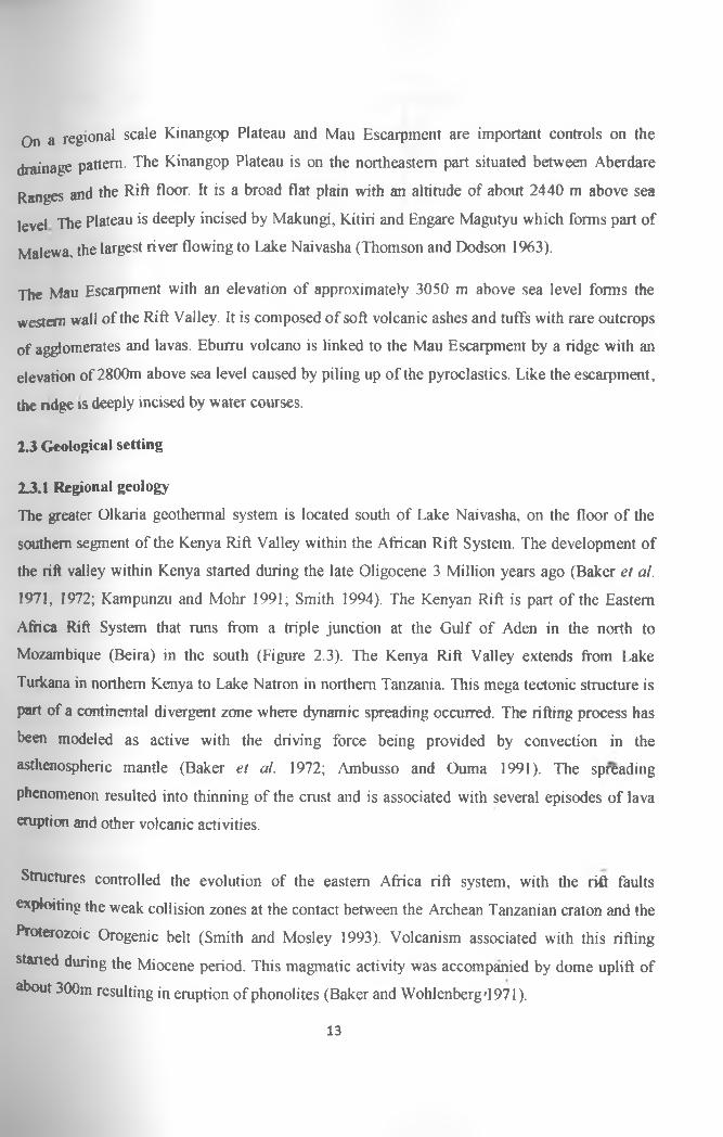
2 J .I Regional geology
The greater Olkaria geothermal system is located south of Lake Naivasha, on the floor of the
southern segment of the Kenya Rift Valley widiin the African Rift System. The development of
the rift valley within Kenya started during the late Oligocene 3 Million years ago (Baker et al.
1971, 1972; Kampunzu and Mohr 1991; Smith 1994). The Kenyan Rift is part of the Eastern
Africa Rift System that runs from a triple junction at the Gulf of Aden in the north to
Mozambique (Beira) in the south (Figure 2.3). The Kenya Rift Valley extends from Lake
Turkana in northern Kenya to Lake Natron in northern Tanzania. This mega tectonic structure is
part of a continental divergent zone where dynamic spreading occurred. The rifting process has
been modeled as active with the driving force being provided by convection in the
asthenospheric mantle (Baker et al. 1972; Ambusso and Ouma 1991). The spreading
phenomenon resulted into thinning of the crust and is associated with several episodes of lava
eruption and other volcanic activities.
Structures controlled the evolution of the eastern Africa rift system, with the rift faults
exploiting the weak collision zones at the contact between the Archean Tanzanian craton and the
Proterozoic Orogenic belt (Smith and Mosley 1993). Volcanism associated with this rifting
started during the Miocene period. This magmatic activity was accompanied by dome uplift of
*b°ut 300m resulting in eruption of phonolites (Baker and Wohlenberg'1971).
13

Figure 2.3: The Great Rift Valley system (Modified from Dunkley et al. 1993)
The evolution of the rift was sequential with massive and extensive Pliocene eruption of
trachytic ignimbrites in the central area, forming the Mau and Kinangop tuffs and was followed
by block faulting. A second faulting episode, which followed the ignimbrite eruptions, resulted
in the formation of the graben structure as known today. A graben is a long structure compared
to its width that is lower relative to the blocks on either side (Billings 1972). In the developing
graben, fissure eruptions of trachyte, basalt, basaltic trachy-andesite and trachy-andesite occurred
(Baker et al. 1971). The plateau rocks that filled the developing graben were then block faulted
to create high angle normal faults within the rift floor. The fractures apparently served as
conduits for the Quaternary volcanic activity of mafic to felsic composition.
t
14

The most intense volcanic activity occurred within the central sector o f the rift where the
volcanic succession is 5 km thick (estimated from seismic data and information from geothermal
wells drifted in Olkaria) (Simiyu et al. 1995).
2.3.2 Local geologyThe greater Olkaria volcanic complex is characterized by numerous volcanic centers of
Quaternary age and is the only area within the Kenya nft with occurrences of comendite on the
surface (Thompson and Dodson 1963; Omenda 2000). Magmatic activity in Olkaria occurred in
the Pleistocene age and continued to Recent as indicated by the Ololbotut comendite dated at
180±50 year B.P, using carbonized wood from a pumice flow associated with the lava (Clarke et
ai. 1990). Other Quaternary volcanic centers adjacent to Olkaria include Longonot volcano to the
southwest and Ebumi volcanic complex to the north (Figure 2.4). Whereas the other volcanoes
are associated with calderas of varying sizes, Olkaria volcanic complex does not have any clear
caldera association. However the presence of a ring of volcanic domes in the east, south, and
southwest has been used to invoke the presence of a buried caldera (Naylor 1972; Virkir 1980;
Clarke et al. 1990). Seismic wave attenuation studies for the whole of the Olkaria area also
indicate an anomaly in the area coinciding with the proposed caldera (Simiyu et al. 1998). The
geology of Olkaria is dominated by Pliestocene-Holocene comendite rhyolite flows, basalt,
trachyte and tuff (Omenda 1998). The Mau tuffs are the oldest rocks that crop out in the Olkaria
area. These rocks are common in the area west of Olkaria Hill, but are absent in the east due to
an east dipping high angle normal fault that passes through Olkaria Hill (Omenda 2000).
t
15

Figure 2.4: Quaternary volcanic centers (Modified after Muchemi 2000)
Data from lithological logs of earlier drilled wells indicates that there is a basalt (Olkaria basalt),
underling the Upper Olkaria volcanics in the area to the east of Olkaria Hill. This lithological
unit, however, is not encountered in the wells drilled in Olkaria West field. The formation varies
tn thickness from 100 m to 500 m. The surface geology is mainly domendite lavas and their
16

equivalents, ashes from Suswa and Longonot volcanoes with minor trachytes and
basalts (Thompson and Dodson 1963, Ogoso-Odongo 1986, Omenda 2000),
2 j j structural geology and tectonics
Structures in the Greater Olkaria volcanic complex include; the Olkaria fault. Gorge Farm faults,
Suswa lineament, and the Ol’Njorowa Gorge (Figure 2.5). The faults are prominent in the
Olkana Central and Olkarta West fields but are scarce in the Olkana Domes area, possibly due to
the thick pyroclastic cover (Ndombi 1981, Omenda 1998). The NW-SE and WNW-ESE faults
are thought to be the oldest and are associated with the development of the main Rift Valley. The
Gorge Farm fault in the northeastern part extends to Olkaria Domes area and displaces the
Ol’Njorowa Gorge in strike slip orientation. The most recent structures in the area are the N-S
faults. Hydroclastic craters located on the northern edge of the Olkaria Domes area mark
magmatic explosions, which occurred in a submerged terrain. These craters form a row along
where the extrapolated caldera rim trace passes.
pyroclastic
t
17

S T R U C T U R A L M A P O F O L K A R IA
Figure 2.5: Olkaria ring structure (Modified from Clarke et al 1990)«•»
tyke swarms exposed by the Ol’Njorowa Gorge trend in a NNE direction further attesting to the
recent reactivation of faults with that trend. The Ol’Njorowa Gorge was thought to have been
formed by faulting but the feature is known today to have been as a result of a catastrophic
outflow of Lake Naivasha during its high stands (Clarke et al. 1990). Volcanic plugs (netks) and
felsic dikes occurring along the Gorge further attests to the fault control in the development of
this feature. Subsurface faults have also been encountered in most Olkaria wells (Karingithi 1996).
18

2.4 HydrogeologyThe hydrogeology of Olkaria area is significantly controlled by tectonics, topography, geology
and climatic aspects. Recent tectonic activity has modified the fracture patterns and created
regions o f enhanced permeability enabling mainly meteoric recharge into the system. The
Kinangop Plateau and Mau Escarpments are high altitude areas with high precipitation,
especially the Mau Escarpment. This provides meteoric water and hydrogeological gradient
enabling an axial flow towards the Rift floor and Olkaria (Figure 2.6).
EBURRUGEOTHERMALFIELD
OLKARIA vGEOTHERMALXFIELD
Piezometnc contour (masl)LONGONOT
------► Lateral flow
' —— — Surface water divide
0 50kmOfNjorowaGorge
Figure 2.6: Regional hydrogeological map
19

Xlie main recharge paths are the NNW-SSE and NW-SE east dipping Rift faults exposed on the
Vfau Escarpment. Rejuvenated N-S Rift floor faults and fractures control a lateral component of
ground water flow into the geothermal system but have a shallower influence than the major rift
fu m ing faults that provide deep recharge. The regional NE and NW faults such as Olkaria
fracture and Suswa lineament that cut across the Rift from the margins also contribute to local re
charge into the geothermal system. Lake Naivasha is the main surface water body and
contributes to the recharge of the system through a subterranean outflow system.
4 ,
I
20

CHAPTER THREE
3.0 METHODOLOGY
The methodology adopted in this study was dedicated towards achieving the set objectives of
the project. The main study themes included; review of the surface geology, review of
petrochemistry data, lithological studies based on well logs and petrographic analysis to
identify secondary or alteration minerals. Clay analysis for clay identification was also done
and finally available chemical data of thermal fluids was used to calculate and predict
subsurface temperatures. The project was conceived and undertaken in five main stages, the
arrangement of the primary stages and the activities are presented by the flow chart in figure
3.1 below.
Figure 3,1: A flowchart of the five primary stages adopted in the study
21

The main materials used to accomplish the various tasks in this project included;
• Geological logs for wells OW-710, OW-23 obtained from Kengen.
• Geological map of scale 1:10000
• Topographical maps (Sheet No 133/4)
• Computer programs; ArcGIS, Rockworks and Canvas 9.
3.1 Data sourcing and handling
The data used in this report was made available by Kenya Electricity Generating Company and
from laboratory analytic results. The data consisted of; the analyzed water samples, prepared
geological logs and reports on the selected subfields. Major laboratory work was done on
samples from well OW-912A since this was a new well while intermittent analysis was done on
the other wells for quality control. For the purpose of this report, geological and geochemical
data from wells OW-23, OW-710 and OW-912A were admitted. Out of the raw data from the
aforementioned wells singling out the suitable analytical data that would best represent the
geology and aquifer temperatures was done based on some important aspects e.g. representative
data and quality.
3.2 Data interpretation
During this task geological maps were acquired and analytical data results obtained were
analyzed and synthesized using various computer programs including; Surfer, ArcGIS,
Rockworks and Canvas 9. ArcGIS and Canvas 9 were useful in digitization of georeferenced
maps. The Surfer and Rockworks softwares were used to generate temperature Iso-maps and
Litho-stratigraphic maps.
3.3 Field work
The first field exploration was undertaken from 2nd to 14th September 2010. The main work
during this field work concentrated on well OW-912A, OW-23 and OW-710 and jnvolved
mapping of the wells (Figure 3.2). Selection of rock cuttings was done and specifically samples
ottt OW-912A were sorted in the Coreshed. It is important to note the sampling guidelines as
^ e d by Omenda (1998) were adhered to during sample selection and sorting such that samples.
22

8
8
83-
8
8
194000 196000 198000 200000 202000 204000■ «--------------1_________ I_________I_________ I___
Olkaria North West
OlkanaWest
OlkariaCentral
East
Olkaria North East
1OW-710
Olkaria East @
OW-23 ^
OlkariaSouth
East
N
A
OlkariaDomes
OW-912A ©------1--------------1-----
194000 196000M eters
0 2.200I__________I
| | | |198000 200000 202000 204000
8
o>
8
8
i - S
8
§
Figure 3.2: Location of study wells (modified from Muchemi 2000)
Preliminary analysis was done using a binocular microscope of the sample cuttings in order to
identify lithological units penetrated, secondary minerals and subsurface structures. Sample
cuttings were later selected at 50 meter intervals for XRD analysis. The second field campaign
was undertaken from 2nd January to 12 January 2011. The work done during this period involved
collection of data available on thermal fluid and subsequent analysis.
4\
I
23

3.3 Laboratory methods
3 3 I Stereo microscope analysis
Stereo microscope analysis is a visual method for preliminary analysis and semi quantitative
form of describing rock and pore characteristics from drill cutting samples (Tiaine el al. 2002).
The analysis during this stage was done using the Wild Heerbrugg binocular microscope. Each
sample was scooped from the sample bag into a Petri dish and then washed with clean water to
remove impurities and dust. Wetting the cuttings was necessary to enhance visibility of samples
including obscure features such as finely disseminated sulphides e.g. pyrite. The sample was then
placed on the mounting stage of the binocular microscope and among the essential features noted
were the colons) of the cuttings, rock types, grain size, rock fabric and original mineralogy,
alteration mineralogy and alteration intensity.
3.3.2 X-ray diffractometer analysis (XRD)
The x-ray diffraction is used to identify individual minerals especially clays and zeolites
(Cathelieau et al. 1985). The X-ray technique complements other methods, including optical
light microscopy. Samples were selected from all the lithologic units in 50m interval and
analyzed for clays. The <4 microns fractions were prepared for X-ray diffraction by use o f a rock
crusher. Finely grounded rock was then mixed with water to form a paste which was then
mounted on a glass slide. A Shimadzu 600 diffractometer was used with Cuka radiation (at 40 kV
and 50mA). Automatic divergence slit, fine receiving slit and graphite monochromatic count data
were collected from 2°-14° at intervals of 0.02° - 20 for a period of 1 second. Count data were
collected from 4°-56° at intervals of O.O4°-20 for time of 1 second. The procedure of preparing
clay sample preparations and XRD analysis are indicated in Appendix 1A and Appendix IB
respectively. The clay results for well OW-912A are tabulated in Appendix III.
3.3.3 Petrographic microscope analysis
Representative samples from all the lithological units encountered in well OW-912A were taken
and thin sections were prepared for petrographic studies. The petrographic microscope was used
to. confirm the rock type, alteration minerals not observed by the binocular microscope and to
study the mineralogical evolution.
24

CHAPTER FOUR
4.0 r e s u l t s
4.1 S u r f a c e geology of OlkariaThe surface geology of Olkaria area is very intricate and complex (Thompson and Dodson
1063) The main lithological units can be summarized as follows;
• Basalts
• Tephrites
• Trachytes
• Rhyolites
• Comendite
• Pyroclastics
Basalts
The Olkaria basalts are bluish grey and are younger compared to those that underlie Kinangop
volcanics and the Kijabe basalts. They are vesicular with vesicles of up to 2.5 cm in diameter and
may vary from finely porous rocks to scoracious. The basalts exposed at the periphery o f die area
are more porphyritic and slightly older than the others in area. The fine textured basalts that form
cones near the southern end of the Ol'Njorowa Gorge are usually purplish maroon or reddish
brown and finely textured rocks but porous. They are, however, extremely tough rocks
containing few small plagioclase phenocrysts. The reddish color is due to erosion and oxidation
hastened by the large surface area of those porous rocks. The coarse textured basalts are less
prone to weathering and retain their typical bluish grey color.
Teph rites
A few small volcanic plugs project through the Gamblian lake beds west of I.ake Naiva$ha and
Spears unrelated to the volcanism in the area. They are formed by rocks that are fined grained,
bluish grey and sparsely distributed amygdaloidal vesicles. These rock are Tephrites and extend
from west of Lake Naivasha to Ndabibi Plains.
25

Trachytes
Trachytes are found in most parts of Naivasha area occurring in both the Kinangop and Mau
escarpments succession as valley lava flow and in the more Recent volcanic series of Longonot
that extends to Olkaria. The trachytes are interbedded with the supposed Kamasian lacustrine
deposited pyroclastics. They are grey medium to coarse grained porphyritic lavas. Weathering
lias altered their characteristic grey color to lighter shades of greenish gray. In more advanced
stages of alteration, iron oxides are formed either in the phenocrysts or in a whole rock and
appear as pale shades of maroon. Weathering frequently also accentuates fissility not apparent in
fresh rocks and therefore trachytes frequently appear as fragments. The younger trachytes from
Longonot volcano are fine grained and often highly vesicular making it easier to map their
extents Most of the agglomerates in the southern end of Ol’Njorowa Gorge are mainly trachytic
in composition.
Rhyolites
Non comenditic rhyolite extrusions of the area are confined to an irregular area which curves
around the south western shores of the lake. Other rhyolite craters and plugs are scattered along a
line roughly parallel with the Ol'Njorowa Gorge. The rhyolites are younger than the comendites
and may represent a later phase of volcanism involving common parent magma. In hand
specimen they are pale grey, fined grained to porphyritic rocks with visible quartz. The
pumiceous rhyolites are spongy like, highly porous and whitish to dirty grey and can float on
water for a limited time.
Comendites
Sodic rhyolites of the Naivasha area have been variously described as comendite, pantellerite,
quartz soda trachyte or simply soda rhyolite. The terms comendite and pantellerite are derived from the names of such localities as, comende in San Pietro Island south of Sicily and, the island of Panthellaria. In hand specimen they are dark colored with phenocrysts of quartz, alkali
feldspars, aegirite, arfvedsonite or riebeckite or less common biotite. The comendites are fairly
even y distributed in the central portion of area. The most important exposures are the imposing
26

1 a flows at the north entrance of 01 'Njorowa Gorge and the columnar jointing flows which are
bout 107 m thick and form steep cliffs. Scenically the most impressive features are two
omendite lava plugs known as Fischer’s tower and horse (El barta) (Thomson and Dodson
1963).
Pyroclasties
Ashs agglomerates and tuffs make up a considerable proportion of the volcanics in Olkaria field.
Most volcanics or vents that have ejected ashes have the heaviest accumulations on the western
sides of the cones due to a westerly prevailing wind during the eruption. The ashes are usually
interbedded with other volcanics and have masked lava flows and structures in the area. Figure
4 1 give a geological map of the area showing the spatial relationship of the aforementioned
lithologic units.
LegendRockjiype
Akira pumice
1 1 Alluvial deposits
Basalt
Basalt and hawarte
P>r drastic con as
Ingnimtxites
| Lacustrine sediments
Hawawte lava
Longer ot ash
H Longonot trachyte
j l H Olkaria comend ite
| 0|k#na trachyte
fXmce Pyroclasties
pumice and tuff cones
Figure 4.1: The geological map of Olkaria area (After Thompson and Dodson 1963)t
27

4.2 Lithology
Wells OW-9I2A, OW-23 and OW-710 were drilled to depths of 3000 m, 1292 m and 1801 m
jypectively. The results from binocular and petrographic analysis show that the dominant rock
unit is the pyroclastic and overlies basalts, trachytes, rhyolites and tuffs. The pyroclastics are
yellowish brown and mainly made up of: pumice, obsidian and lava lithic fragments. They are
gocountered from the surface to about 50m below the surface. The tuffs, on the other hand, are
brownish to reddish fined grained rocks. They are light in weight and moderately altered to
clays They are dominating in well OW-710 with a thickness o f about 100m in sections where
they are encountered (Figure 4.2).
The lava flows encountered are mainly rhyolitic, trachytic and basaltic. Rhyolites are light grey
to grey in color with a porphyritic texture, under the microscope they show flow texture and
phenocrysts of quartz and feldspars. They dominate in all wells under study, however they are
encountered at shallower levels in well OW-912A as compared to the other wells (Figure 4.3).
The trachytes are light grey, porphyritic lava with phenocrysts of feldspars. They are mainly
altered to clays and are occasionally highly bleached. It is the most dominant rock unit especially
in well OW-912A.The basalts are brownish to grey, fine grained and moderately altered lavas.
They are distinguished from other formations due to their high content of calcite. They are
mostly encountered at deeper levels the shallowest being at about 500m below surface. The
dominant rock type in well OW-23 is trachyte encountered at extreme depths (Figure 4.4).
28

r
§ 5 5 $ § £ }§ - § § S 3 |
Lithology Index
1M w n
/ r .« X i A t * U
|■ r
t -
^ ® lre Lithology, distribution of hydrothermal alteration minerals and zonation in
well OW-710 (Olkaria Northeast, depth is in meters)
t
29

30
m m u t t t m m ____ m mz i 5V P
5l
S tw u»o ^J 3 r►WAA 5vA
r* A lt e r a t io n m in e ra l
3T Zeoliteo Hite
£ Pyrite'C Epidote3a Chlorite
X ChakedonyCaldte
40-120T 180 300
— *2SO 300‘C — 230 300'C
= <180*C---------- 100-300°C
> 1Figure 4.3: Lithology, distribution of hydrothermal alteration minerals and zonation in well OW-912A (Olkaria Domes, depth
is in meters)
Akaratkm
minerals

Figure 4.4: Lithology, distribution of hydrothermal alteration minerals and zonation in
well OW-23 (Olkaria East, depth is in meters)
4\
9
31

4 3 Stratigraphic correlation
A geological cross-section across wells OW-912A, OW-23, OW-710 in Olkaria Domes, Olkaria
East and Olkaria Northeast is shown in Figure 4.5 below. The figure reveals in detail the
subsurface geology of tine study area. The structures in the area are faults and fractures indicated
by displacement in the rock units and by loss of circulation during drilling resulting in
unconformities within the lithological units. The stratigraphy of Olkaria Domes and Olkaria East
art mostly similar, however, Olkaria Northeast is slightly different. The trachytic unit in Olkaria
Northeast is smaller while the basaltic unit is thicker compared to the other subfields in this
study. Olkaria Northeast and areas closer to Olkaria East are highly faulted, this favors the flow
of thermal fluids making this subfield the most probable productive subfield, however, these
faults are not very obvious on the surface due to thick pyroclastic cover.
4 ,
t
32

Figure 4.5: Geological cross-section between well OW-912A,OW-23 and OW-710

4 4 Petrochemistry of Olkaria field rocks
Various chemical analyses of surface and subsurface rock samples from the Rift flanks and
•jjjjH Greater Olkaria show that, the volcanic complex is composed of rocks ranging in
composition from basalt to rhyolite (Brownel978, Omenda 2000). The chemical analyses of
samples from Olkaria Northeast and Olkaria East fields by MacDonald et al. 1987 and Olkaria
Pomes by Black el al. 1997 (Tables 4.1 and 4.2) were important in determining the exact rock
type and compositional variation. The results indicate that the rocks from Olkaria East and
Olkaria Northeast have composition similar to those of Olkaria Domes generally with somewhat
alkaline compositions.
Table 4.1: Petrochemistry of Olkaria Northeast and East fields. Oxides in % and elements in ppm (MacDonalds et al. 1987)
Rock Comendite Comendite Trachyte Rhyolite T rachyte I rachyte Basalt I rachyte
\Y*U No. 707 706 714 16 16 17 17 17
(a.a.s.01737 1S34 1499 1193 751 1698 1386 702
SiO: 72.37 75.3 6933 75.73 67.1 62.7 5495 64 04Ti^ 0.34 0.17 0.48 0.33 0.72 0.62 0.42 0.8al-6) 11.49 10.58 12.41 9.26 13.26 14.76 15 44 1141F*0) 5.84 4.43 6.64 5.25 6.74 S 933 1082NlaO| 0.13 0.07 0.02 0.16 0.23 0.31 0.21 0.4\IfO 0.02 0 0.06 0.1 0.19 0.13 ' 2.07 0.57CiO 0.33 0.1 0.37 0.11 0.76 0.85 4.77 0.52
~T*,6 4.11 4.64 4.43 1.03 3.88 4.55 449 3.39TTO 4 9 4.53 4 94 5.64 5.45 5.65 3.05 *76Ishi 0 0 0.02 0.02 0.07 0.06 0.34 0.09
~Loi 0.4 0.22 0.55 1 86 1.01 2.13 3 37 3.14Total 99.53 99.75 99.25 99.49 99.41 99.76 9S.44 98 94
f
34

Table 4.2: Chemistry of Olkaria domes. Oxides %, elements in ppm (Black et a l 1997)
“Rock Rhyolite Rhyolite I rachyte Basalt Syenite
903 903 903 903 903
M**-11755-53 1537-35 1221-19 1141-39 209-207
155T" 75.45 77.32 63.48 4691 64 59
-TS5T- 0.14 0 13 046 2.11 0.81
AfcOi 10.61 10.75 1408 15.01 1402
'RIST' 4 47 2.9 6.43 12.3 7.01
006 004 0.19 0.2 0.24
0 0 0.63 6.28 0.47
0.08 0 14 3.16 10.7 1 57
~Na:0 4.36 3 IS 3.81 2.24 465K.0 4 44 5.220.01 5 53 084 4 96P:Os 001 0 0.05 0.21 0.1LOI 0.33 0.29 2.15 3.02 0.87Total 99 96 99 99 99 96 99 82 99 29
The Total Alkalis versus Silica (TAS) diagram in Figure 4.6 is developed from chemical
analysis of the rocks from Olkaria East, Olkaria Northeast and Olkaria Domes fields. The plot
shows that the samples mainly fall in the basaltic, trachytic and rhyolite portions in the TAS
classification. This further helps in in determining the exact rock types in the area.
t
35

Figure 4.6: TAS Classification based on the petrochemical results of Table 4.1 and 4.2
According to Omenda (2000), the Olkaria comendites have high Si02 (71.8-77.3%) and are
strongly depleted in Ti02 (0.13-0.42%), MgO (0-0.16%), CaO (0.08-0.41%), and P20 5 (0.01-
0.02%). Major element variation plots for trachytes and comendites show linear trends for the
variation of T i02 and Fe20} (T) with S i02. The oxides A12C>3, CaO, Na20 , and K20 show the
comendites fall on a trend that is at an angle to the trachyte trend. These trends suggest that most
of the comendites are not related to the trachytes and to one another by simple fractional
crystallization processes. However, those that lie on the same trend as the quartz trachyte
genetically related.
Based on classification in terms of Al203-total iron as FeO diagram (MacDonald 1974) the
Olkaria lavas are pantelleritic (Figure 4.7) and also fall in the comendite field* This
classification separates comendites from pantellerite which have lower Al203, Fe203 (t), CaO,
^ d Na20. Some of the samples plotting in the pantelleritic field have petrographic
characteristics consistent with them being trachytes. These features' include flow-aligned
crystallites (Trachytic texture) and the absence of quartz phenocrysts. Their major element
36

concentrations are also different from the comendites in that they have higher contents of MgO,
pC20 , and AI2O3 (12.5%). These rocks are therefore, true trachytes and can be referred to as
qggrtz trachytes due to their high silica contents. The trachytes are typically potassic
(K’C^N^O) but the total alkalis are similar to those of the comendites, which have nearly equal
proportions of Na20 and KiO.this classification indicate that pantellerite may have been formed
from fractional crystallization of the comendites hence single source or same magma chamber.
Figure 4.7: Classification in of terms of AhC^-tota! iron as FeO diagram (MacDonald 1974)
4.5 Description and distribution of hydrothermal alteration minerals
The distribution of hydrothermal minerals in wells OW-710, OW-912A and OW-23 is shown in
the aforementioned Figures 4.2, 4.3 and 4.4 respectively. Below is a description of the
hydrothermal alteration minerals encountered in the Olkaria Northeast, Olkaria Domes and
Olkaria East wells.
Caldte *
Calcite is a widely distributed alteration mineral occurring in all the three Olkaria wells. They
*** mainly deposited in Vesicles, fractures and as veins as white massive or colourless
deposits. Calcite replaces plagioclase phenocrysts, pyroxenes and volcanic glass. The crystal
37

morphology of calcite is variable and ranges from individual thin-bladed crystals to equant
n e e d le - lik e crystals. Calcite crystals are deposited in veins at between 500 - 1600 m in well
0VV-71O (Figure 4.2) and 600-1100 m in well OW-23 (Figure 4.5). In well OW-912A calcite
persist up to 2200 m (Figure 4.3). The calcite crystals were analyzed qualitatively by X-ray
diffraction and the most intense peak ranged from about 3.02 to 3.05A. A calcite diflfractogram
is shown in Figure 4.8.
Chalcedony
Chalcedony occurs from the surface to the bottom in all the study wells except in well OW-912A
where it disappears at 2500 m. They are cryptocrystalline and range from colourless, white, or
hluish-grey in colour. They are deposited in vesicles, fracture and also as veins. They generally
have massive, banded or botryoidal texture. At greater depths where temperatures are high,
chalcedony in vesicles is transformed or was completely transformed into quartz but the
chalcedonic texture was still preserved.
/
38

Chlorite
Chlorite occurs between 0 and 1300 m in well OW-710, 0 and 1250 m in well OW-23 and 438
(Ol940 m in well OW-912A (Appendix III). Chlorite shows a wide distribution and a big
variability in colours, forms and textures. It varies in colour from light-to-dark green, has low
birefringence and occasionally shows anomalously blue, brown or purple interference (Figure
4 9) In the upper levels of the volcanic sequences, chlorite appears in small intergranular
patches whereas at the deepest levels, chlorite is idiomorphic and forms in radial aggregates in
veinlets and vugs in association with: quartz, calcite, epidote, amphibole and pyrite. Within the
veins, chlorite occurs as microspherules enclosed within epidote, but it may also replace primary
pyroxene. XRD analyses of chlorite show conspicuous peaks at 7.0-7.2A and 14.0-14.5A in the
untreated, glycolated and oven heated samples. A diffractogram indicative of chlorite is shown
in figure 4.10.
Figure 4.9: Vescicle filling chlorite In thin section showing a low birefringence and an anomalously blue, brown and purple interference
4'»
t
39

Figure 4.10: DifTractograms of clays showing unchanged peaks at 7.1lA and 14.2 A for chlorite and 10.13A for illite in the Air dried, glycolatqd and the oven heated samples

Epidote
The first appearance of epidote is from 850 m and is evident up to 1580 m in well OW-710.In
well OW-912A it occurs between 1000 and 2900 m, however it is absent in well OW-23. Epidote
shows a systematic textural development with increasing depth. In shallow zones crystals are
anhedral and form fine grained aggregates and in deeper zones they are idiomorphic, tabular,
radiated or fibrous. Epidote is found filling fractures, vesicles, and replacing primary plagioclase
and pyroxene and in most cases forms mineral associations with mainly quartz, chlorite and
sometimes calcite, wairakite and pyrite.
Illite
Illite is detected below 600 m in the three wells. The mineral is light green to white in colour,
replaces K-feldspar and occurs as a vein and vesicle filling mineral. XRD analyses o f illite
show no change at the 10 A in the untreated, glycolated and oven heated samples. An illite
XRD pattern clearly indicating the 14 A and 10 A d-spacing is shown in figure 4.11.
t
41

Lm (
Cos)
Figure 4.11: Difrractograms of (plays showing strong illite peaks at aroundlOA and minor chlorite component with peaks at
7.14A and at 14.41A in the Air dried, glycoiated and the oven heated samples

r
pyritepyrite crystals are present below 500 m to the bottom in the three wells, however, they become
^ from 1580m in well OW-710. Pyrite occurs as euhedral cubic crystals with brassy yellow
luster in reflected light. Tiny cubic pyrite crystals were deposited in fractures, vesicles and veins
and as disseminations in the groimdmass. XRD analysis of pyrite indicates strong peaks at 3.13
A, 2.71 A, 2.42 A, 2.21 A and 1.91 A as shown in the XRD diffractogram (Figure 4.12).
•« ■
•• -
3
Vc • -m i
-
4
M
l 1
9 \«r
A
• n m m m
2 -T h « a-S c* »EH3«43t1iOWINe^AiO(»'fWTtl Di YEAS - S»sgnn VlN< OOt D?W£A; VI Vfl DO. «!♦ XAM fM • Tyo« m\T1> oe»«a - s a r . 4 006 ’ - E-e « coc
optrascr* y v o e m t 1K | now .
Figure 4.12: Diffractogram of pyrite showing strong peaks at 3.13A, 2.71 A, 2.42A, 2.21 A
and 1.91 A
Actinolite
An actinolite mineral is green to greyish green in colour, and forms radiating fibers or acicular
uystals and also massive to granular aggregates in the groundmass and has a moderate
birefringence. The mineral is formed as a replacement of ferromagnesian minerals in
association with epidote and chlorite. Actinolite appeared in the deeper hotter parts of well
OW-710 but was conspicuously absent in well OW-912A and OW-23.
43

r
4.6 Hydrotherma* zonat>ongasefj on this study encountered mineral assemblages in Olkaria have been grouped into four
basic depth and temperature related alteration zones. The zeolite-chlorite-(smectite) zone (1),
initiated around 40°C, reflects die alteration of the most unstable primary minerals, namely
volcanic glass and olivine, into smectite clays (Fe-rich saponites) and a variety of low-
temperature Ca-Si zeolites including analcime, clinoptilolites and stilbite. There is a transition
zone of mixed-layer clay defined by the point at which smectite starts to become unstable
(~200°C) and is gradually replaced by an inter-stratified smectite-chlorite. The underlying illite-
chlorite zone (2) is characterized by the presence of discrete chlorite, which begins to form
around 230°C (Lagat 2004). The chlorite-epidote-illite zone (3) correlates with the first
appearance of epidote, believed to form at temperatures exceeding 230-250°C. Other
temperature dependent minerals associated with the latter two zones include the high-
temperature zeolite wairakite (>200°C), prehnite (>240°C) and wollastonite (>260°C).
The first appearance of the amphiboles and actinolites formed by the alteration of pyroxene at
temperatures exceeding 280°C, defines the epidote-actinolite zone (4). At Olkaria, grossular
garnet has also been sporadically identified within these zones (Browne 1981) and at the deepest,
hottest parts (>350°C). In addition to the minerals described above, pyrite is widespread across
the entire temperature range and its abundance is believed to be controlled by the system
permeability and supply of H2S (e.g. Reyes 1990). Calcite is also abundant in well-cuttings, with
its stability extending to temperatures around 290-300°C. Chalcedony and amorphous silica are
observed at temperatures below 180°C, but at higher temperatures crystalline quartz is formed.
Other secondary minerals that are typically identified in Olkaria geothermal system include:
pyrrhotite, chalcopyrite, sphalerite, apatite and titanite.
Lagat (2004) described the depth-zonal distribution of some of the main temperature dependent
alteration minerals throughout the domes subfield - quartz (>180°C), epidote (>230-250°C),4 ,
wollastonite (>260°C), and Al-free amphibole (>280°C). A cross-section through Olkaria
Domes, Olkaria East and Olkaria Northeast subfields showing the hydrothermal zonation is
shown in figure 4.13. The cross-section shows the four zones describe aboye.
44

Figure 4.13: Distribution of hydrothermal mineral zonation with depth across wells OW-912A, OW-23 and OW-710 in Olkaria
geothermal field (Units in meters)
i t

Fluid geochemistry of the Olkaria fields
•The fluid chemistry of Olkaria geothermal field has marked similarities and variations from
jubfield to subfield and sometimes from one well to another. Chloride concentration variations
from various subfields are indicated in figure 4.14 below.
Figure 4.14: Average chloride concentration from Olkaria fields
According to Karingithi (1992, 1993, 19%), Karingithi and Wambugu (1997) the Olkaria East
fluid discharges rich bicarbonates-carbonate concentration of 200ppm and Cl' concentrations of
350 ppm. While the Olkaria North east fluids are bicarbonate-carbonate waters with relatively
higher Cl' concentrations of 600 ppm.
Olkaria central wells results indicate Cl' concentrations of about 300ppm except for well OW -
201 which gives high values of 700 ppm. Olkaria central wells have relatively high
concentrations of reservoir CO2 concentrations, therefore they are bicarbonate waters similar to
those in Olkaria west field (Wambugu 1995), and have high chloride concentration of about
200ppm compared to those from Olkaria East. Karingithi (1999) suggested that Olkaria domes
wells discharge mixed sodium bicarbonates-chloride- sulphates fluids with chloride
concentrations of 270 ppm.
46

4 8 Solute geothermometry
The temperature functions of Fournier and Porter (1982) for quartz geothermometers, Fournier
( j979) and Giggenbach (1988) for Na/K are utilized in the estimation of the reservoir
temperatures. Reservoir temperatures calculated based on the K/NA ratio indicates aquifer
temperature values at Olkaria East fields as 250°C (Amorsson et al. 1983). Olkaria Northeast
fields results indicates values of 290°C on average (Figure 4.15), however K/Na data is limited
and, therefore, in the current study quartz geothermometry is applied.
Figure 4.15: Temperatures inferred from the K/Na ratios
According to Fournier and Potter (1982), quartz geothermometry indicates that Olkaria East
wells have reservoir temperatures of 260°C. The Olkaria Northeast wells have values of 270°C
while Olkaria central and Olkaria domes is 259°C about 236°C respectively (Figure 4.16).There
is a significant reduction in temperatures towards Olkaria west field to values of about 180°C.
t
47

300
O 250
i 200
| 150 w| 100
1 i i i i i0
O lkaria O lkaria O lkaria East O lkaria O lkaria
N ortheast W e st Central D om es
Olkaria subfields
Figure 4.16: Temperatures inferred from the quartz geothermometry
/
48

CHAPTER FIVE
50 DATA SYNTHESIS AND THE CONCEPTUAL MODELING
5 .1 Geology and petrochemistry
The Olkaria geothermal system is characterized by complex tectonic activity associated with the
evolution of the Eastern African Rift System (EARS). The volcanism is thought to have started
during the Pleistocene period and resulted in various geomorphologic features including the
Longonot and Eburru volcanoes. The hydrogeology of Olkaria area is strongly controlled by the
eastern and western rift flank faults, the rift floor faults and the rock types. The main recharge for
the system is mainly from the rift faults and the NNW-SSE faults. The rock petrochemistry
reveals that the rocks in the area are not related genetically by simple fractional crystallization.
5.1.1 Surface geology of Olkaria
The surface geology as revealed by field data can be divided into five main rock types namely;
basalts, trachytes, rhyolites, comendite and pyroclastics. The Olkaria basalts are younger
compared to those that underlie the Kinangop volcanics and the Kijabe basalts. They form cones
near the southern end of the Ol’Njorowa Gorge and are usually reddish brown and finely
textured but porous rocks. They are, however, extremely tough rocks containing small
plagioclase phenocrysts. The trachytes are found in more recent volcanic series of Longonot and
extend to Olkaria. The trachytes are interbedded with Kamasian lacustrine sediments and
pyroclastics. Older trachyte frequently appears as fragments in younger agglomerates with some
of these agglomerates being exposed at the southern end of Ol’Njorowa Gorge. The younger
trachytes from Longonot volcano are fine grained and often highly vesicular with few exceptions
being non-porphyritic.
Non-comenditic rhyolite extrusions of the area are confined to an irregular area which curves
around the south western shores of the Lake Naivasha. Other rhyolite craters and plugs are
scattered along a line roughly parallel to the Ol’Njorowa Gorge. The rhyolites are younger than
the comendifes and may represent a later phase of volcanism involving common parent magma.
Sodic rhyolites of the Naivasha area have been described as comendites and are distributed fairly
49

eve» <n the central portion of area (Omenda 2000). The most important exposure is the lava
flows at the north entrance of 01 'Njorowa Gorge and the columnar jointing flows. They are
jbout 107 m thick and form steep cliffs often capped by a skin of black obsidian presumably of
the same composition. Volcanic ash, agglomerates and tuffs make up a considerable proportion
of the volcanics in the Olkaria area and most vents (Eniption centers) that ejected the ashes have
the heaviest accumulations on the western sides of the cones due to an easterly prevailing wind
during the eruption.
5.1.2 Lithostratigraphy
The lithostratigraphy of Olkaria geothermal field as revealed by well log data indicate that
Olkana Domes area is composed of pyroclastic, tuff, rhyolites, trachyte and basalt. Hie Olkaria
Northeast comprises of tuff layers and basalts with intercalations of pyroclastics. However, the
basalt layer is more pronounced in this field. In Olkaria East the trachyte and rhyolite are the
major lithological units. Subsurface structures inferred from noticeable displacements in the rock
units and by loss of circulation/retums in the reconstructed lithostratigraphy are faults and
fractures around Olkaria Northeast and Olkaria east subfields. The structures are not seen on
surface due to pyroclastic cover masking the area.
Permeable zones in the wells were interpreted by loss of circulation/retums and hydrothermal
alteration mineralogy patterns. Loss of circulation/retums recorded at shallow depths above the
groundwater table due to a fractured rhyolite lava. Well OW-912A generally has good
permeability compared to the other wells under study, this is inferred from the lithostratigraphy
indicating major loss of returns or circulation (Figure 4.3). In Well OW-710 loss of
circulation/retums is experienced mainly at shallow depths while in Well OW-23 the losses"were
encountered at 500 m and at 1200 m.
5.1.3 Petrochemistry
The chemical analysis of the rocks from Olkaria East, Olkaria Northeast and Olkaria Domes
fields indicate that rocks from Olkaria East and Olkaria Northeast have compositions, similar to
those of the Olkaria Domes generally with somewhat alkaline compositions. The Olkaria
comendites have high S1O2 (71.8-77.3%) and are strongly depleted in TiQ2 (0.13-0.42%), MgO
(0-0.16%), CaO (0.08-0.41%), and P2 O5 (0.01-0.02%). The trachytes have relatively low values/
50

0f Si02 (62.7-69.3%) and slightly higher values of TiCh (0.72-0.8%), MgO (0.13-0.19%), CaO
(0.52-0.85%), and P2O5 (3.76-5.65%). The basalts have low SiC>2 (54.95%) but are highly
enriched in CaO (4.77%). Major element variation plots for quartz trachytes and comendites
show linear trends for the variation of Ti02 and Fe20i with Si02. The oxides AI2O3, CaO, Na20,
and K2O show that the comendites fall on a trend that is at an angle to the quartz trachyte trend.
These trends suggest that most of the comendites are not related to the quartz trachytes and to
one another by simple fractional crystallization processes.
Based on classification in terms of AI2O3 and total iron (FeO), the Olkaria trachytes are
pantelleritic and have higher AI2O3, Fe203, CaO, and Na20. Their major element concentrations
are also different from the comendites in that they have higher contents of MgO, Fe203, and
AI2O3 (12.5%). However the petrographic characteristics are consistent with them being
trachytes. These features include flow-aligned crystallites (Trachytic texture) and the absence of
quartz phenocrysts. These rocks are, therefore, true trachytes and can be referred to as quartz
trachytes due to their high silica contents.
5.2 Fluid geochemistry and geothermometry
Thermal fluids in Olkaria West field contrast sharply with those in the fields under study. In the
Olkaria West field, the discharge fluids are typically rich in bicarbonates but the chloride content
is very low. The Olkaria East fluid discharges have similar bicarbonates-carbonate concentration
of <200 ppm as those in the Olkaria Northeast but low chloride concentrations of 200-350 ppm.
Fluid geochemistry indicates high chloride concentration in the Olkaria Northeast field; this
means the fluids are typically geothermal waters. Permeability is a factor here, the deep fractures
and faults providing channels for chloride anions from a magmatic source to admix with tfiermal
fluids and reach the surface. Olkaria Domes wells discharge is of a mixed sodium bicarbonate-
chloride-sulphate type with low mean chloride concentrations of 181.5-269.9 ppm indicating
bicarbonate and chloride thermal fluids are mixing.
Reservoir temperatures have been calculated using chemical geothennometers and the results
indicate that the K/Na ratio function by Amorsson el al. (1983) gives average reservoir
temperature values of 258°C for the Olkaria West and 290°C for Olkaria Northeast (Figure
4.15). ;
51

Reservoir temperatures calculated using the quartz geothermometry function by Fournier and
potter (1982) show Olkaria East wells have reservoir temperatures of 255°C. The Olkaria
Northeast wells have values of 270°C while Olkaria Domes field have values of 240°C (Figure-
4.16).
5.3 Hydrothermal alteration and zonation
The upper 50 m of lithostratigraphy in each well is unaltered and is mainly composed of
pyroclastics. The zone immediately below is zeolite-chlorite alteration which represents low
grade alteration. Minerals characterizing this zone include zeolites, chlorite, chalcedony, pyrite
and calcite. The illite-chlorite zone is not extensive as the zeolite-chlorite zone and occurs below
700 m deep in each well, the index minerals in this zone are illite, chlorites and pyrites. The
moderately high temperature zone of chlorite-illrte-epidote zone occurs below 1200 m and the
main index mineral is epidote indicating temperatures of over 250°C. The hottest zone is the
actinolite-epidote zone (Table 5.1) which is over 1500m deep in well OW-710. The mineral
assemblages (Epidote and actinolite) representing this zone were not observed in well OW-912A
and in OW-23 indicating that it is confined to well OW-710. Well OW-710 is therefore located
above a hot area probably overlying a hot plutonic body.
Table 5.1: Hydrothermal alteration mineral in the study wells (X) indicate presence o f
mineral)
H y d r o t h e r m a l a lt e ra t io n m in e ra ls . O W -710 O W -23 O W -912A T e m p e r a t u r e s
Z e o lite X X X 40-120°C
P y r ite X X X -
C a lc ite X X X 100-300°C
C h a lc e d o n y X X X <180°C
Illite X X X 180-300°C
C h lo r ite X X X 230-300°C
E p id o te X X 250-300°C
A c t in o l it e X >300°C
52

5 .4 Conceptual model
The development of a conceptualized model of the Greater Olkaria geothermal area was first
proposed by Sweco and Virkir (1976) and since then a model has been developed in the Olkaria
pomes area. The model developed relied mainly on hydrodiermal alteration minerals as
temperature proxies. For a geothermal system to exist, the following conditions must be present;
a heat source, recharge fluid, permeable formations and/or structures to allow water to percolate
though and time for heat transfer from the hot intrusive to the water which is the media.
Occurrences of acidic and pantelleritic rock units on the surface and at shallow depths with
comendites at deeper levels indicate a highly differentiated magma chamber source. Extrusion^
and intrusions of magma occur along the N-S structure and the ring structure; this resulted into
the emplacement of a shallow heat source in form of brittle ductile plutonic bodies. Th^
volcanicity in Olkaria is still active and is attributed to tectonics leading to increased activity in
the area as evidenced by the recent Ololbotut eruption, which has been dated at 180±50 yrs
(Clarke et al. 1990). Due to these evidences the heat source in Olkaria area is a hot plutonic body
below 6 km and this is corroborated by Seismic studies. According to (Simiyu et al. 1998) th^
presence of a semi molten magma bodies, whose depths to their roots are not known, have bee^
determined by shear wave attenuation below the 6 km depth.
Evidence from alteration minerals show that actinolite mineral is encountered at a relatively
shallower depth in well OW-710 (Olkaria Northeast field). The actinolite is an alteration miners
formed by contact metamorphism when a hot magmatic body intrudes the country rock^-bakin^
the areas adjacent to it (aureole).Using this and the high calculated temperatures from flui j
geochemistry, the Olkaria Northeast field therefore an upflow zone. The shallower hot body
heats the fluids and flows in convectional cell manner, the fluids outflow to Olkaria East ar^
Olkaria Domes. These outflow zones are characterized by relatively low temperatures inferr^j
from the mineralogy and calculated temperature from fluid geothermometry. Olkaria We^t
showed the lowest temperatures indicating that it is an inflow zone or a recharge area.
53

A conceptual model through A, B, C, and D (Figure 5.1, 5.2 and 5.3) therefore is been developed
in this report. The model indicating that hot fluids ascend from Olkaria Northeast because of the
jngh temperatures inferred by actinolite presence and high geothermetric temperatures. The high
temperatures are due a hot Plutonic Body intruding the Northeast field as the heat source. The
thermal fluids outflow laterally towards Olkaria East and Olkaria Domes area as inferred from
moderate temperatures recorded from alteration and fluid geothermometry.
0 2,200I___________ I
Figure 5.1: Cross-section line (A, B, C, and D)
/
54

2000 ma si
Z *o l i t # < N c n t *
lllit*-c M e rit*
Epidcte-ilkte-cHorite
Actiro lits-Ep idccc
LEGEND
Hot outflow
Cold inflow
Hot intrusion
Figure 5.2: Integrated conceptual geothermal model using results of wells OW-7IO, OW-
23 and OW-912A {NB/ Figure not drawn to scale).
f
55

YtyttW *. ’VlV0 \vana
O tkarta S o m e s
O W - 9 1 2 A
♦ V ♦ ♦ ♦ ♦ ♦ ♦ ♦ W s .
R e c h a rg e <VJ« V * V *
L E G E N D
U p fto w > z o n e
Ig n e o u sin trus io n s
Figure 5.3: A three dimensional conceptual model of Olkaria geothermal field
f
56

CHAPTER SIX
6. 0 CONCLUSION AND RECOMMENDATIONS
6.1 Conclusion
The surface geology of Olkaria geothermal field is dominated by basalts, trachytes, rhyolites,
comendite and pyroclastics. Non- comenditic rhyolite extrusions of the area are confined to an
irregular area which curves around the southwest on the shores of the Lake Naivasha. The
rhyolites are younger than the comendites and may represent a later phase of volcanism
involving common parent magma. The Lithostratigraphy from well logs reveals that Olkaria
Domes area is composed of pyroclastic, tuff, rhyolites, trachyte and basalt while Olkaria
Northeast are tuff layers and basalts with intercalations of pyroclastics. Olkaria East has
trachyte and rhyolite as revealed by well OW-23 stratigraphy.
Major subsurface structures (mainly faults and fractures) are inferred from the loss of
circulation/retums and displacements in the reconstructed Lithostratigraphy. The structures
mainly occur around Olkaria East and Northeast (Figure 4.5). These areas are therefore
permeable, making it possible for geothermal fluids to be transmitted, consequently, they are
favorable areas for drilling. The chemical analysis of the rocks from Olkaria East, Olkaria
Northeast and Olkaria Domes fields indicate that rocks from Olkaria East and Olkaria Northeast/
have compositions similar to those the of Olkaria Domes generally with somewhat alkaline
compositions. Based on classification in terms of AI2O3 and total iron (FeO), the Olkaria
trachytes are pantelleritic with higher AI2O3, Fe203, CaO, and Na20. Major element variation
plots for quartz trachytes and comendites show a linear trend for the variation of Ti02 and Fe203
with Si02.
Reservoir temperatures calculated using chemical geothermometers by K/Na ratio function by
Amorsson et al. (1983) indicate average temperature values of 258°C for the Olkaria West and
290°c for Olkaria Northeast. The quartz geothermometric function by Fournier and Potter
(1982) is however much more reliable and indicates 255°C, 270°C and 240°C for Olkaria East,
Olkaria Northeast and Olkaria Domes respectively. Olkaria Northeast is thus the hottest and
57

these results mirrors those inferred from alteration minerals (Figure 4.13). Therefore this
validates and proves that geothermal fluids can be used as temperature proxies in geothermal
conceptual modeling.
Based on hydrothermal alteration minerals assemblages in the three subfields, four alteration
zones are recognized with a possibility of one or two sub-zones. The zones are: (1) The zeolite-
chlorite zone; (2) The illite-chlorite zone; (3) The epidote-illite-chlorite zone; and 4) Actinolite-
epidote zone. The zones infers temperatures of 0-225°C, 230-248°C, 248-300°C and >300°C,
respectively. A conceptual model based upon thermal fluids and alteration mineral
geothermometry suggests that Olkaria Northeast is the upflow with hot fluids ascending here and
outflows laterally towards Olkaria East and Olkaria Domes area. A major intrusive in Northeast
field inferred from young rocks in the area is the heat source, the ductile body transfers heat by
conduction and eventually heats up the fluids forming thermal fluids.
6.2 Recommendations
1. Olkaria Northeast and to lesser extent Olkaria East should be given priority during
production drilling since they are upflow areas as indicated by high temperatures.
2. Structural geology also indicates that the aforementioned subfields host the main
subsurface structures that should be targeted during drilling.
3. Olkaria West should be a reinjection field since natural inflow is in that area.
4. Simulation studies using reservoir data should be done to refine the model developed in
this project.
5. Reinjection index test should be carried out to map the extent of the reservoir in the
Olkaria Northeast field.
6. More studies should be carried out incorporating more data from more wells in each
field, this will help in making a more comprehensive model of the Olkaria geothermal
field.
/
58

r e f e r e n c e s
Ambusso, W.J., Ouma, P.A., 1991: Thermodynamic and permeability structure of Olkaria
Northeast field. Geothermal Resource Council Transactions, 15, 237-242.
Amorsson, S., Gunnlaugsson, E., Svarvarson, H., 1983: The chemistry of geothermal waters in
Iceland III. Chemical geothermometry in geothermal investigations. Geochemica
Cosmochemica Acta, 46, 1513-1532.
Baker, B.H., Mohr, P.A., Williams, L.A.J., 1972: Geology of the eastern rift system of Africa.
Geological Society o f America, Special paper 136, 1-67.
Baker, B.H., Williams, L.A.J., Miller, J.A., Fitch, F.J., 1971: Sequence and geochronology of
the Kenya Rift volcanics. Tectonophysics, 11, 191-215.
Baker, B.H., Wohlenberg, J., 1971: Structural evolution of the rift valley, Nature, 229, 538-542.
Billings, M.P., 1972: Structural Geology 3rd edition. New Delhi, pp. 249-250.
Black, S„ Macdonald, R., Kelly, M R., 1997: Crustal origin of per alkaline rhyolites from
Kenya: evidence from U-series disequilibria and Th-isotopes. Journal o f Petrology, 38,
277-297.
Browne, P.R.L., 1981: Petrographic study of cuttings from drilled wells at the Olkaria
Geothermal field, Kenya. Kenya Power Company.
Browne, P.R.L., 1978: Hydrothermal alteration in active geothermal fields. Annual Review
Earth and Planetary Sciences, 6, 229-250.
Cathelineau, M., Oliver, R., Garfias, A., 1985: Mineralogy and distribution of hydrothermal
mineral zones in Los Azufres (Mexico) geothermal field. Geothermics, 14, 49-57.
Clarke, M. C. G., Woodhall, D. G., Allen, D., Darling, G., 1990: Geological, volcanological and
hydrogeological controls of the occurrence of geothermal activity in the area surrounding
Lake Naivasha. Ministry o f Energy, Nairobi, report 150,138 pp.
Colin. H., Patrick, B., 2000: Mixed-layered clays in geothermal systems and their effectiveness
as mineral geothermometers. Proceedings of World Geothermal Congress May-June
2000, Kyushu-Tohoku Japan, viewed 5th January 2012, http://w w w,geotlterma 1 -
energy, org.
59

Dunkley P.N Dunkley, P. N„ Smith, M., Allen, D. J. and Darling, W. G., 1993.The geothermal
activity and geology of Northern sector of the Kenya Rift Valley. British geological
survey research report, 93, 1.
Ferguson, G., Grasby, S.E., and Hindle, S.R., 2009: What do aqueous geothermeters really tell
us? Geofluids, 9, 39-48.
Fournier, R.O., 1997: Chemical geothermometers and mixing models for geothermal systems.
Geothermics, 5, 41-50.
Fournier, R.O., Potter, R.W., 1982: A revised and expanded silica (quartz)
geothermometer. Geothermal Resource Council Bulletin, 11-10, 3-13.
Fournier, R.O., 1979: A revised equation for the Na/K geothermometer. Geothermal Resources
Council Transactions, 3,221-224.
Giggenbach, W.F., 1991: Chemical techniques in geothermal exploration; in applications of
geochemistry in geothermal reservoir development. Cosmochemica Acta, pp. 119-144.
Giggenbach, W.F., 1988: Geothermal solute equilibria, derivation of Na-K-Mg-Ca
geoindicators. Geochemica Cosmochemica Acta, 5,2749-2765.
Kampunzu, A.B., Mohr, P., 1991: Magmatic evolution and petrogenesis in the East Africa Rift
system. Springer-Verlag, 2, 85-136.
Karingithi, C.W., 1999: Olkaria Domes geothermal field Kenya, geochemical model. Kengen,
unpublished internal report
Karingithi, C.W., Wambugu, J.M., 1997: Olkaria Geochemical Model. Kenya Power
Company, unpublished internal report.
Karingithi, C.W., 19%: Olkaria East Production Field geochemical report. Kenya Power
Company, unpublished internal report.
Karingithi, C.W., 1993: Olkaria East Production Field geochemical report. Kenya Power
Company, unpublished internal report.
Karingithi, C.W., 1992: Olkaria East Production Field geochemical report. Kenya Power
Company, unpublished internal report.
Lagat, J.K., 2004: Geology hydrothermal alteration minerals and fluid inclusions studies of
Olkaria domes geothermal field, Kenya. M.Sc. thesis, University of Iceland. 79 pp.
t1
60

Macdonald, R., Baginski, B., Leat, P.T., W hite, J.C., Dzier2anowski, P., 2011: Mineral
stability in peralkaline silicic rocks: Information from trachytes of the Menengai volcano,
Kenya. Journal o f Petrology and geochemistry, 125, 553-568.
Macdonald, R., Davies, G.R., Bliss, C.M., Leat, P.T., Bailey, D.K., Smith, R.L., 1987:
Geochemistry of high silica per alkaline rhyolites, Naivasha, Kenya rift valley. Journal o f
28, 979-1008.
Macdonald, R.,1974: Nomenclature and petrochemistry of the peralkaline oversaturated
extrusive rocks. Bulletin o f Volcanology, 38, 498-516.
Muchemi G.G., 2000: Conceptualized model of Olkaria geothermal field, Kengen, 13 pp.
Mungania, J„ 1992: Preliminary field report on geology of Olkaria volcanic complex with
emphasis on Domes area field investigations. Kenya Power Company, 38 pp.
Ogoso-Odongo, M.E., 1986: Geology of Olkaria geothermal field. Geothermics, 15, 741-748.
Omenda P.A 1998: The geology and structural controls of the Olkaria geothermal system Kenya,
Geothermics 27, 55-755.
Omenda, P.A., 2000: Anatectic origin for Comendite in Olkaria geothermal field, Kenya Rift;
Geochemical evidence for syenitic protolith. African Journal o f Science and Technology.
Science and Engineering Series, 1, 39-47.
Naylor, W. I., 1972: The geology of the Eburru and Olkaria geothermal projects. Geothermal
Resource Exploration Prospects, viewed 18lhFebruary 2010, http.V/www.os.is/gogn/unu-
ntP-sc/UNU -GTP-SC -10-0102.
Ndombi, J.M., 1981: The structure of the shallow crust beneath the Olkaria geothermal field,
Kenya, deduced from gravity studies. Journal o f Volcanology and Geothermal
Research, 9, 237-251.
Utami, P., Browne, P.R.L., Simmons, S.F., Suroto, J., 2005: Hydrothermal alteration mineralogy
of the Lahenndong geothermal system north Sulawesi, Paper presented at the 27th
geothermal workshop 2005, New Zealand, viewed 18th February 2008,
http://www.science.auckland.ac.nz/uoa.
61

Reyes, A.G., 1990: Petrology of Philippine geothermal system and the application of alteration
Mineralogy to their assessment. Journal o f Volcanology and Geothermal Research, 43,
279-304.
Sarolkar. p., 2000. Assessment of Tatapani geothermal field, India, based on hydrothermal
mineral assemblage. Proceedings of World Geothermal Congress June 2000,
Kyushu-Tohoku Japan,viewed 5th January 2012, http://www, geothermal-energy.org.
Simiyu, S.M., Oduong, E.O and Mboya, T.K., 1998: Shear wave attenuation beneath the Olkaria volcanic field. Naivasha Kenya, KenGen.
Simiyu, S.M., Omenda, P.A., Antony, E.Y., Keller, G.R., 1995: Geophysical and geological
evidence for the occurrence of shallow intrusion in Naivasha sub-basin of the Kenya rift.
Proceedings of AGU Fall 1995, viewed, 5th January 2010, http j /www.asu.on: meetings.
Smith, M„ 1994. Stratigraphy and structural constrains on mechanisms of active rifting in the
Gregory Rift, Kenya. In: Prodehl, C., Keller, G.R., Khan, M.A. (ed.), Crustal and upper
mantle structures of the Kenya rift. Tectonophysics, 236, 3-2.
Smith, M and Mosley, P., 1993: Cnistal heterogeneity and basement influence on the
development of the Kenya rift, East Africa. Tectonics, 12, 591-606.
Virkir, S., 1976: Feasibility report for the Olkaria Geothermal Project. Nairobi Kenya, United
Nations.
Thompson, A.D and Dodson, R: 1963. Geology of the Naivasha Area. Geological Survey
o f Kenya, Nairobi, Kenya, Government Printer.
Tiainen, S., King,H., Cubitt,C., Karalaus,E., Prater,T., Willis,B., 2002: A new approach to
reservoir description and characterization. Examples from copper basin, Australia.
Proceedings of Australian petroleum products and exploration association conference
Adelaide Australia, viewed 5th January 2012, http:// www.eps.mq.edu.au.
Virkir Consulting Group., 1980: Geothermal development at Olkaria. Naivasha Kenya, Kengen.
Wambugu, J.M., 1995: Geochemical up-date of Olkaria West geothermal Field. Naivasha
Kenya, Kengen.
62

APPENDIX IA: Preparation of samples for clay analysis
1. Into a clean test tube place approximately two spoonfuls of drill cuttings. Wash the cuttings to
Remove the dust with distilled water and fill the tube to approximately two-third lull with
distilled water. Place the tubes in a mechanical shaker for 4-6 hours depending on the intensity of
alteration of the cuttings.
2. Allow the particles to settle for 1 -2 hours, until those particles less than approximately 4 A are
left in suspension. Pipette a few millilitres from each tube and place approximately 10 drops on a
labeled glass plate, not making the film thick. Make a duplicate of each sample and let them dry
at room temperature overnight.
3. Place one sample at the desiccators containing glycol (C2H6O2) solution and the other in a set
of desiccator containing hydrated calcium chloride (CaCl2.H20). Store it at room temperature for
at least 24 hours. Thicker samples need more time at least 48 horns.
4. Run both sets of samples in the range 2-14° at intervals of 0.02°, 26 for a time of 1 second on
XRD machine.
5. Place one set of samples (usually the glycolated one) on an asbestos plate and insert in a
preheated oven. Heat the samples at 500-550°C for one hour making sure the oven temperatures
do not exceed 600°C. When the samples have cooled, nm them in the range 2-14° on the XRD
machine. -
/
63

APPENDIX IB: A flow chart on procedure for XRD analysis
/
64

APPENDIX II: Well logging data of OW-912A based on binocular microscope analysis
STRATIGRAPHY OF WELL 912A
Depth Rock description Rock type hydrothermal
alteration
minerals
0-50 Brownish, light grey, unconsolidated
rock cuttings consisting of soils,
pumice, obsidian, quartz and glass
fragments
Pyroclastic Oxides
Clays
50-72 Greenish to greenish grey, fine
grained lava. Porphyritic with quartz
and feldspars and moderately
altered.
Rhyolite Oxides
Clays
72-170 Brownish to reddish brown fine
grained lava, porphyritic with quartzif ip tr»nfiorotoK' fr\XVIUJ UIJ 11 1J lllOUVi UIV1J 1C
highly oxidized. Pyrite disseminated
in ground mass, vein filling with
pyrite.
Rhyolite Oxides
Clays
/
170-190 Brownish grey fine grained almost
fresh lava it is porphyritic with
quartz and feldspars
Rhyolite Oxides
Clays
190-252 Grey almost fresh lava. It is fine
grained and crystalline it is
porphyritic with quartz and feldspars
Rhvolite Oxides
Clays
it is weakly altered.
Greenish grey tine grained quartz Rhyoifre oxides
and feldspars weakly porphyritic
lava. It’s moderately altered to----------- -----*----
Clays
65

brownish and greenish.
287-310 Light grey fine grained quartz and
feldspars physic lava, it is weakly
altered to brownish clay
Rhyolite Oxides
Clays
310-342 Greenish grey to greenish grey finecrrcunoH nunrt? n"r*V> lava
altered.
Rhyolite OxidesPlmrc-
342-360 Light grey to greenish grey fine
grained feldspar rich phyric lava it is
moderately altered and appears
fractured
Trachyte Oxides
Clays
Pyrite
360-442 Loss of returns/ circulation - -
442-450 Light grev weaklv porphyritic lava
with feldspars, it is fine grained and
moderately altered to clays. It’s also
bleached
Trachyte Oxides
Clays
Pyrite
450-458 Loss of returns/ circulation - -
458-460 Light grey weakly porphyritic lava
with feldspars. It is fine grained and
moderately altered to clays. It’s also
bleached.
Trachyte Oxides
/Clays
Pyrites —r 4«otww—IUU T opr at rahime/ aitahIoti amVJX IVUUUiJI VUWIUUUVU1
488-514
514-522
Light grey fine grained quartz and
feldspar rich lava. It is silicic,
moderately altered and porphyritic.
Loss of returns/ circulation
Rhyolite Clay
Oxides
pyrite ~
522-580 Light grey fine grained quartz and
feldspar rich lava. It is silicic,
Rhyolite Clay
Oxides
66

moderately altered and porphyritic. pyrite '
calcite
580-584 Light grey fine grained feldspar rich Trachyte Clays
lava. It is moderately altered and has Pyrite
some green coloration. Chlorite
calcite
584-586 Loss of retums/circulation - -
586-588 Light grey to greenish grey fine Trachyte Clays
grained feldspar rich phyric lava. pyrite
Has veins filled with quartz. Also Chlorite
pyrite is disseminated in the
groundmass. It is moderately altered
and appears fractured.
calcite
588-654 Loss of retums/circulation - -
654-662 Light grey to greenish grey fine Trachyte Clays
grained feldspar rich phyric lava. Pyrite
Has veins filled with quail/. Also Quartz
pyrite is disseminated in the Chlorite
groundmass. It is moderately altered calcite
and appears fractured. /
662-666 Loss of retums/circulation - ‘
666-668 Light grey to greenish grey fine Trachyte Pyrite
grained feldspar rich phyric lava. Clays -
Has veins filled with quartz. Also Quartz
pyrite is disseminated in the Chlorite
groundmass. It is moderately altered
and appears fractured.4 ,
668-670 Loss of retums/circulation - "
670-680 Light grey to greyish grey fine Trachyte Oxides
feldspar rich phyric lava. Has veins - Clays
filled within quartz .Also pyrite is*
Pyrite
67

disseminated in the groundmass. It’s
moderately altered and appears
fractured.
Quartz
680-682 Loss of retums/circulation - -
682-684 Light grey to greenish grey fine Trachyte Oxides
grained feldspar rich phyic lava. Has Clays
veins filled with quartz .Also pyrite Pyrites
is disseminated in groundmass Its
moderately altered and appears
fractured.
Quartz
684-790 Loss of retums/circulation - -
790-792 Light grey to grey fine grained Trachyte Clays
quartz and feldspar phyric lava. It’s Chlorite
moderately altered to greenish and Pyrite
brownish clays. Epidote
792-846 Loss of retums/circulation - -
940-944 Grey to grayish green fine grained Trachyte Clays
lava. It’s porphyritic with feldspars. Chlorite
It also has veins filled with quartz .It Pyrite
is fractured and shows moderate to Epidote
high intensity of alteration. Quartz
944-990 Dark grey feldspar phyric lava. It is Basalt Clays
highly porphyritic and has reddish Chlorite —
brown tinges on the groundmass. It Pyrite
also has abundant calcite It appears
fractured and moderately altered to
Epidote
brownish and greenish clays.
990-1012 Grey to brownish grey feldspar Basalt Clays
phyric lava. It is moderately to Chlorite
highly porphyritic .It shows flow •- Pyrite
banding, veined and fractured. It’s / Epidote
68

moderately altered to brownish,
greenish and reddish brown.
1012-1018 Greyish green fine feldspar phyric
lava. It is moderately porphyritic and
veined. It’s also chloritized at some
depths It’s moderately altered to
greenish and whitish clays.
Trachyte Clays
Chlorite
Pyrite
Hpidote
Calcite
1018-1040 Brownish grey fine grained
moderately altered lava. It is
moderately too high porphyritic. It
has reddish brown tinges on the
groundmass. It is also veined and
fractured
Basalt Clays
Chlorite
Pyrite
Epidote
(abundant)
Calcite
1040-1070 Dark grey moderately porphyritic
with feldspars lava. It has reddish
brown tinges on the matrix. It is also
veined and appears fractured.
Basalt Clays
Chlorite
Pyrite
Epidote
(abundant)
calcite
1142-1152 Grayish to grayish green feldspar
phyric lava. It is weakly porphyritic
and slightly chloritized. It is also
veined.
Trachyte Clays
Chlorite
Pyrite
Epidote «.
(abundant)
quartz
1152-1162 Light brown brownish grey lava. It
is porphyritic with feldspar. It is also
fractured. Moderately altered to
clays
Trachyte Clays
Chlorite
Pyrite
Epidote
(abundant)
1162-1174 Greyish to greyish green feldspar Trachyte , Clays
69

phyric lava. It is weakly porphyritic
and slightly chloritized. It is also
veined.
Chlorite
Pyrite
Epidote
(abundant)
1174-1178 Grey to grayish brown feldspar
phyric lava It is fine grained and has
reddish brown alterations.
Trachyte Clays
Chlorite
Pyrite
Epidote
(abundant
1178-1180 Light grey to grey, quartz phyric
lava. It is fine grained and
crystalline, It also shows flow
banding and moderately altered to
brownish and greenish clays.
Rhyolite Clays
Chlorite
Pyrite
Epidote
(abundant
1180-1194 Loss of retums/circulation
1194-1214 Light grey to grey fine grained
feldspar phyric lava. It shows flow
banding and also veined it is weakly
to moderately altered
Trachyte Clays
Chlorite
Pyrite
1214-1194
Light grey to greyish feldspar rich
lava. It is fine grained, veined and
fractured. Shows moderate intensity
of alteration.
Trachyte Clays
Chlorite
Epidote
Quartz _
1412-1416 Light grey to bluish grey highly
porphyritic with feldspar. It shows
flow banding, veined and appears
fractured. It is moderately altered to
clays
Trachyte Clays
Chlorite
Epidote
pyrite
1416-1422 Pale green to light weakly
porphyritic lava. It is rich in fields
and appears fractured. It also has
Trachyte
*/
Clays
Chlorite
Epidote
70

brownish alteration
1422-1438 Grayish to greenish grey fine
grained lava.
It is weakly porphyritic and highly
altered.
Trachyte Clays
Chlorite
Epidote
14422-1456 Brownish grey, bluish grey weakly
to moderately porphyritic with
feldspar. It is fracture and shows
moderately to high intensity of
alteration
Trachyte Clays
Chlorite
Epidote
1456-1468 Brownish to reddish brown fine
grained vesicular lava. It appears
light weight and moderately altered
to white clays
Tuff Clays
Chlorite
Epidote
1462-1472 Light grey to bluish grey fine
grained lava. It is porphyritic with
feldspar. Moderately altered to
bluish and brownish clays
Trachyte Clays
Chlorite
Epidote
pyrite
1472-1486 Light grey to brownish grey fine
grained feldspar phyric lava. It is
veined and highly altered to reddish
brown
Trachyte Clays
Chlorite
Epidote
pyrite
1486-1490 Greenish grey fine grained
porphyritic lava. It is moderately
altered and appears fractured.
Trachyte Clays
Chlorite
Epidote
pyrite ~
1490-1540 Light grey to brownish grey phyric
lava. It has quartz and feldspar rich,
moderately altered and appears
fractured.
Rhyolite
%
/
Clays
Chlorite
Epidote
pyrite
71
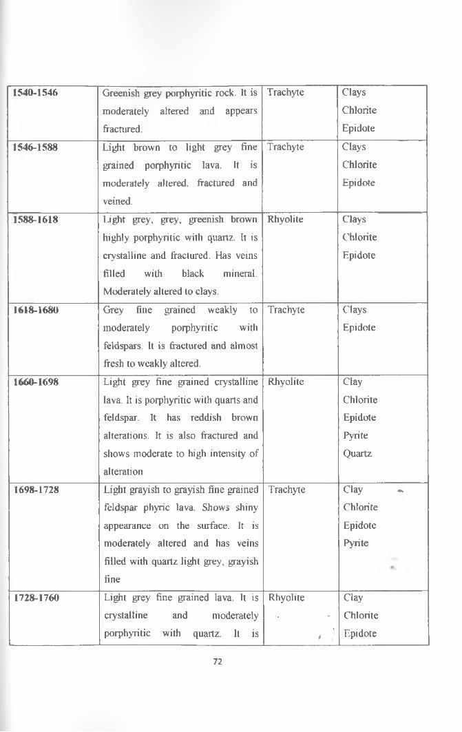
1540-1546 Greenish grey porphyritic rock. It is
moderately altered and appears
fractured.
Trachyte Clays
Chlorite
Epidote
1546-1588 Light brown to light grey fine
grained porphyritic lava. It is
moderately altered, fractured and
veined.
Trachyte Clays
Chlorite
Epidote
1588-1618 Light grey, grey, greenish brown
highly porphyritic with quartz. It is
crystalline and fractured. Has veins
filled with black mineral.
Moderately altered to clays.
Rhyolite Clays
Chlorite
Epidote
16I&-1680 Grey fine grained weakly to
moderately porphyritic with
feldspars. It is fractured and almost
fresh to weakly altered.
Trachyte Clays
Epidote
1660-1698 Light grey fine grained crystalline
lava. It is porphyritic with quarts and
feldspar. It has reddish brown
alterations. It is also fractured and
shows moderate to high intensity of
alteration
Rhyolite Clay
Chlorite
Epidote
Pyrite
Quartz
1698-1728 Light grayish to grayish fine grained
feldspar phyric lava. Shows shiny
appearance on the surface. It is
moderately altered and has veins
filled with quartz light grey, grayish
fine
Trachyte Clay -
Chlorite
Epidote
Pyrite
1728-1760 Light grey fine grained lava. It is Rhyolite Clay
crystalline and moderately •• Chlorite
porphyritic with quartz. It is * Epidote
72

fractured and weakly altered. Pyrite
Quartz
1760-1776 Brown to brownish grey weakly
porphyritic with feldspar lava. It is
fine grained and highly altered to
greenish and whitish clays. It is also
veined and fractured.
Trachyte Clay
Chlorite
Epidote
Quartz
1776-1784 Light grey fine grained feldspar
porphyritic lava. It is fractured and
also moderately altered
Trachyte Clays
Chlorite
Epidote
1784-1794 Grayish to grayish brown fine
grained phyric lava. It is veined,
fractured and moderately altered to
clays
Trachyte Clays
Chlorite
Epidote
1828-1842 Dark grey to grey feldspar phyric
lava. It is fine gained and
moderately to highly porphyritic.
Highly altered to greenish, brownish
and whitish clays.
Trachyte Clay
Chlorite
Epidote
Quartz
1842-1850 Light to whitish green bleached
rock.
It is weakly porphyritic with
feldspar. It is also highly altered.
/
2100-2178 Brownish grey, fine grained weakly
porphyritic. It is fractured and has
quartz veins and moderately to
highly altered. Also has reddish
brown tinges and is shinny on the
surface.
Trachyte Epidote
Clays
Biotite
Quartz
Chlorite
2178-2212 Greenish grey fine grained phyric Trachyte Epidote
lava with feldspar. It is moderately *
/ Clays
73

altered and has reddish brown Quartz
alterations. Also appears fractured. Chlorite
2212-2300 Brownish grey moderately Trachyte Epidote
porphyritic lava with feldspars. It is Clays
moderately to highly altered and Quartz
appears fractured. Chlorite
2300-2356 Light grey, light brown fine grained Trachyte Clays
quartz and feldspars porphyritic Chlorite
lava. It is moderately altered to
clays.
Epidote
2356-2372 Brownish grey moderately Trachyte Clays
porphyritic lava with feldspars. Chlorite
Moderately altered to brownish
clays and appears fractured
Epidote
2372-2438 Light brown fine grained feldspar Trachyte Clays
rich lava. It has veins filled with Chlorite
quartz and moderately altered to
clays.
Epidote
2438-2458 Light grey to greyish feldspar rich Trachyte Clays
lava. It is fine grained, veined and Chlorite/fractured. Shows moderate intensity Epidote
of alteration. Quartz
2458-2468 Light grey to greyish feldspar rich Trachyte Clays —
lava. It is fine grained, veined and Chlorite
fractured. Shows moderate intensity Epidote
of alteration. Quartz
2468-2504 Light grey to grey fine grained Trachyte Epidote
phyric lava. It is veined, fractured Clays
and flow banding is evident and it’s Quartz
moderately altered. - Chlorite
2504-2514 Grey to brownish grey fine grained Trachyte , Epidote
74

phyric lava. It’s moderately to
highly altered to brownish clays and
appears fractured.
Clays
Chlorite
2514-2556 Greyish fine grained feldspar and
quartz rich crystalline lava. It is
moderately to highly altered and it’s
also moderately porphyritic.
Rhyolite Epidote
Clays
Chlorite
2556-2606 Light grey to greyish fine grained
feldspar rich lava. It is moderately
altered to brownish. It is also veined
and fractured.
Trachyte Epidote
Clays
Chlorite
Quartz
2606-2608 Loss of retums/circulation - -
2608-2624 Light grey to greyish fine grained
feldspar rich lava.It is moderately
altered to brownish. It is also veined
and fractured.
Trachyte Epidote
Clays
Chlorite
Quartz
2624-2626 Loss of retums/circulation - -
2626-2658 Light grey to greyish fine grained
feldspar rich lava. It is moderately
altered to brownish. It is also veined
and fractured.
Trachyte Epidote
Clays
Chlorite
Quartz
2658-2680 Brownish grey to grey fine grained
phyric lava. It is moderately altered
to brownish clays and it appears
fractured.
Trachyte Epidote
Clays -
Chlorite
Quartz
2680-2730 Light brown light feldspar rich
moderately porphyritic lava. It
shows moderate to high intensity of
alteration
Trachyte Epidote
Clays
Chlorite
2730-2742 Loss of retums/circulation -
2742-2770 Light grey feldspar rich moderately Trachyte , Epidote
75

porphyritic lava. It is crystalline and
shows moderate to high intensity of
alteration to brownish clays.
Clays
Chlorite
Pyrite
2770-2786 Loss of retums/circulation - -
2786-2794 Light grey to light brown fine
grained porphyritic lava feldspar. It
is moderately altered and also
appears fractured.
Trachyte Epidote
Clays
Chlorite
Pyrite
2794-2816 Light grey to brownish grey fine
grained highly porphyritic with
black phenocrysts on feldspar
matrix. It is silicic and shows
moderate to high intensity of
alteration to clays. It has reddish
brown tinges on the groundmass.
Trachyte Epidote
Clays
Chlorite
Pyrite
2816-2832 Brownish grey to grey fine grained
lava. It is fine grained and fractured.
It is fine grained and fractured. It is
porphyritic with feldspars. It also
shows flow banding. It is moderately
altered to clays.
Trachyte Epidote
Clays
Chlorite
Pyrite
/
2832-2840 Bluish to bluish grey fine grained
feldspar phyric lava. It is silicic and
highly altered to clays.
Trachyte Epidote
Clays «.
2840-2856 Brownish grey fine grained lava.
Shows flow banding and fracturing
Its moderately altered to brownish
and bluish clays
Trachyte Epidote
Clays
Chlorite
2856-2864 Grey fine grained moderately to
highly altered lava. Shows flow
Trachyte*
t
Epidote
Clays
76

banding and it’s also silicic and
altered to brownish.
Chlorite
2864-2874 Loss of retums/circulation - -
2874-2884 Greyish to bluish fine grained
feldspar rich moderately porphyritic
lava. It is moderately altered to
bluish clays.
Trachyte Epidote
Clays
Chlorite
2884-2958 Light brown to brownish grey
grained phyric lava. It shows
moderate to high intensity of
alteration to bluish and brownish
clays.
Trachyte Epidote
Clays
Chlorite
2958-2990 Light grey light brown moderately
porphyritic lava with feldspars. It is
moderately altered and has reddish
brown tinges on the matrix.
Trachyte Epidote
Clays
Chlorite
77

APPENDIX III: Clay analysis and interpretation
Ref ID
Depth (m)
Air dried
D-spacing
(intensity)
Glycolated
D-spacing
(intensity)
Heated
D-spacing
(intensity)
Interpretation
50-60 7.19(60), 10.14(50) 7.19(38), 10.06(44) Kaolinite, illite
78-80 7.12(8) 7.03(17) 7.02(6), 7.19(19) ilhte
98-100 7.17(4), 10.11(31) 7.16(30), 10.1(30) 7.10(9), 10.01(58) Illite, kaolinite
316-320 7.07(48), 10.32(100) 7.09(42), 10.09(10) 10.10(100) Illite, kaolinite
358-360 7.01(91), 9.91(100) 7.02(99), 10.19(29) 10.09(100) Kaolinite, illite
378-380 7.10(21), 10.19(12) 7.12(18) 7.15(7), 10.13(13) Kaolinite, illite
400-402 7.13(46), 10.05(36) 7.12(56), 9.97(56) 7.08(56), 7.18(38) Illite, kaolinite
416-424 7.40(14),10.30(34) 7.41(100)10.00(40) 7.16(5), 10.14(100) Illite, kaolinite
438-440 14.00(100) 7.06(97), 10.27(99) 7.39(15), 10.10(100) illite, chlorite
458-460 7.05(100), 15.06(23) 7.34(77), 17.01(38) 7.32(42), 10.09(25) Chlorite, illite
478-480 7.07(64), 10.06(23) 7.19(47),10.00916) 7.30(180,10.10(45), Chlorite, illite
518-520 7.11(100), 10.42(19) 10.3(12), 14.04(12) 7.36(32), 10.03(100) Chlorite, illite
538-540 7.11(100) 7.10(100), 7.38(29) 7.01(29), 7.39(100) Chlorite
558-560 7.07(100), 10.14(9) 7.41(100), 10.07(21) Chlorite, illite
578-580 7.07(46), 10.13(100) 7.07(30), 9.91(100) 7.0195), 10.039100) Chlorite, illite
638-640 7.10(100), 10.16(10) 10.02(7),14.2(49) 7.16(40),10.03(15) Chlorite, illite
656-660 7.12(100), 10.29(11) 7.15(100), 10.14(7) 7.31(46), 10.05(22) Chlorite, illite
698-700 10.09(9), 14.47(41) 10.5(10), 14.77(37) 7.11(33), 14.19(100) Chlorite, illite
730-732 7.06(100), 10.30(27) 7.10(99), 10.00(19) 7.24(38), 9.87(38) Chlorite, illite
738-740 7.10(100), 10.16(33) 7.05(67), 10.01(100) Chlorite, illite
742-744 7.07(100), 10.13(10) 7.11(99), 14.03(36) Chlorite, illite
754-756 7.07(100), 10.03(16) 7.26(99), 10.22(24) 7.01(24), 9.97(44) Chlorite, illite
/
78

778-780 7.07(100), 9.97(10) 7.11(100), 9.94(19) 7.06(26), 10.07(27) Chlorite, illite,
838-842 7.07(100), 10.09(97) 7.08(99), 14.10(38) 7.29(10), 14.02(38) Chlorite, illite
878-880 7.09(100), 10.14(65) 7.13(99), 10.03(59) 7.12(67), 10.02(100) Chlorite, illite
918-920 7.06(100), 10.09(77) 7.05(100), 9.98(64) 7.27(30), 10.03(100) Chlorite, illite
Chlorite/illite
958-960 7.10(100), 10.14(10) 7.06(100), 17.54(5) 7.21(39), 9.98(89) Chlorite, illite.
Smectite
978-980 7.11(100), 9.80(7) 7.08(100), 9.97(7) 12.288(100) Chlorite, illite
998-1000 7.17(100), 10.12(17) 7.14(99), 10.07(13) 7.02(38), 9.99(100) Chlorite/illite,
smectite
1018-1020 7.11(100), 10.19(5) 7.12(99), 10.17(23) 7.09(43), 10.01(9) Chlorite, illite,
smectite
1082-1084 7.10(100), 10.11(26) 7.12(99), 10.17(23) 10.01(93), 14.14(43) Illite/Chlorite
1098-1100 7.05(100), 10.24(19) 7.18(99), 10.26(30) 7.27(71), 9.90(88) Chlorite, illite
1120-1124 7.08(100), 10.04(24) 7.05(100), 17.36(9) 7.04(75), 9.98(72) Chlorite, illite
1140-1142 7.09(100), 10.22(4) 714.11(26), 16.7(4) 7.14(38), 10.21(12) Chlorite, illite,
smectite
Illite/Chlorite.
1210-1212 7.09(100), 4.13(36) 7.07(100), 12.28(7) 7.12(28), 12.35(26) Chlorite, illite,
Illite/ChloriteSt
1
79

1238-1240 7.06(100), 9.92(25) 7.08(99), 14.08(31) 10.04(95), 14.19(100) Chlorite, illite,
illite/Chlorite
(?)
1254-1256 7.09(100), 14.05(19) 7.08(100), 17.08(3) 7.28(100), 14.17(29) Chlorite, illite,
smectite
1338-1340 7.10(100), 14.13(11) 7,07(100) Chlorite
1356-1360 7.10(100), 10.07(34) 7.07(99), 11.88(18) 7.08(32), 10.06(97) Chlorite, illite,
illite/Chlorite
1380-1382 7.08(100), 11.80(12) 7.08(100), 14.21(7) 7.02(93),12.02(100) Chlorite,
illite/Chlorite
1398-1400 10.02(6), 14.04(16) 7.07(99), 12.14(35) 7.05(21), 14.12(38) Chlorite, illite,
illite/Chlorite
1420-1422 7.07(100), 14.17(3) 7.05(100) 7.34(100) Chlorite.
1490-1494 7.10(100), 9.95(13) 7.08(100), 10.04(9) 7.09(13), 9.89(100) Chlorite, illite,
illite/Chlorite
1518-1520 7.08(100), 10.15(9) 7.08(100), 10.04(6) 7.11(100), 10.04(38) Chlorite, illite,
(minor)
1538-1540 7.16(100), 10.09(9) 7.07(100), 10.29(9) 7.09(48), 10.09(34) Chlorite, illite.
1558-1560 10.02(40), 15.06(24) 7.12(100), 10.46(9) 7.18(52),10.03(43) Chlorite, illite,
smectite
illite/Chlorite.
1588-1592 10.15(28), 14.07(63) 7.10(100), 7.10(5) 7.01(17), 14.17(99) Chlorite, illite,
smectite
illite/Chlorite.
1616-1620 7.07(31), 10.08(51) 7.15(97), 10.13(90) 7.32(41), 9.96(100) Chlorite, illite,
illite/Chlorite.
1702-1706 7.07(100) 7.08(100),14.15(12) Chlorite,
1716-1718 7.09(100), 10.10(40) 7.07(99), 10.09(23) 7.07(31), 9.94(100)
*
Chlorite, illite.
Illite/Chlorite.
80

1718-1720 7.11(25), 10.05(34) 10.05(44), 12.1(99) 9.90(98), 14.03(55) Chlorite, illite.
lllite/Chlorite.
1754-1756 7.08(100), 10.09(95) 7.10(97), 11.92(97) 7.04(16), 14.12(14) Chlorite, illite.
lllite/Chlorite.
1758-1760 7.08(100), 14.13(9) 7.11(100), 14.1(10) 7.21(100) Chlorite,
1808-1812 10.27(22), 14.35(20) 7.10(100), 10.7(24) 7.01(6), 7.30(34) Chlorite, illite.
1828-1832 10.15(20), 14.16(24) 7.06(100), 9.99(18) 7.18(100), 9.92(100) Chlorite, illite.
1836-1840 7.15(100), 14.36(29) 7.14(99), 12.58(42) 7.29(10), 10.04(85) Chlorite, illite.
illite/Chlorite
1842-1844 7.08(52), 10.07(100) 7.07(56), 10.01(99) 7.09(7), 9.91(100) Chlorite, illite.
illite/Chlorite
1854-1856 7.12(100), 14.18(45) 7.13(100), 14.20(9) 10.15(13), 14.10(50) Chlorite, illite.
1876-1880 7.16(10), 10.14(100) 7.00(20), 10.07(99) 7.11(14), 9.91(36) Chlorite, illite
illite/Chlorite
1938-1940 7.11(95), 11.93(100) 7.15(10), 12.04(99) 7.07(5), 12.17(100) Chlorite, illite.
illite/Chlorite
81/