Embed Size (px)
Citation preview
Application Note
WAGO Target Visualization
Example of Alarm Management
A762005e, English Version 1.0.0
ii • Important Notes
Application Note A762005e
Imprint
Copyright 2010 by WAGO Kontakttechnik GmbH & Co. KG All rights reserved.
WAGO Kontakttechnik GmbH & Co. KG Hansastraße 27 D-32423 Minden
Phone: +49 (0) 571/8 87 – 0 Fax: +49 (0) 571/8 87 – 1 69
E-mail: [email protected]
Web: http://www.wago.com
Technical Support Phone: +49 (0) 571/8 87 – 5 55 Fax: +49 (0) 571/8 87 – 85 55
E-mail: [email protected]
Every conceivable measure has been taken to ensure the accuracy and com-pleteness of this documentation. However, as errors can never be fully ex-cluded, we always appreciate any information or suggestions for improving the documentation.
We wish to point out that the software and hardware terms, as well as the trademarks of companies used and/or mentioned in the present manual, are generally protected by trademark or patent.
Important Notes • iii
Application Note A762005e
TABLE OF CONTENTS
1 Important Notes ......................................................................................... 5 1.1 Legal Principles ..................................................................................... 5 1.1.1 Copyright .......................................................................................... 5 1.1.2 Personnel Qualification .................................................................... 5 1.1.3 Intended Use ..................................................................................... 5 1.2 Scope of Validity ................................................................................... 6
2 Functional Range ....................................................................................... 7
3 Components ................................................................................................ 7 3.1 Control Panel CP 104 VGA TV ............................................................ 7
4 Project Creation......................................................................................... 8 4.1 Creating the Target System.................................................................... 8 4.2 Creating a Simple PLC Program ........................................................... 9 4.3 Alarm Configuration............................................................................ 10 4.3.1 Definition of Alarm Classes ........................................................... 10 4.3.2 Creating an Alarm Group ............................................................... 11 4.4 Creating a Simple User Interface......................................................... 12 4.5 Downloading and Testing the Example............................................... 15
iv • Important Notes
Application Note A762005e
Important Notes • 5
Application Note A762005e
1 Important Notes
To ensure quick installation and start-up of the units, please carefully read and adhere to the following information and explanations.
1.1 Legal Principles
1.1.1 Copyright
This document, including all figures and illustrations contained therein, is sub-ject to copyright protection. Any use of this document that infringes upon the copyright provisions stipulated herein is prohibited. Reproduction, translation, electronic and phototechnical filing/archiving (e.g., photocopying), as well as any amendments require the written consent of WAGO Kontakttechnik GmbH & Co. KG, Minden, Germany. Non-observance will involve the right to assert damage claims.
WAGO Kontakttechnik GmbH & Co. KG reserves the right to make any al-terations or modifications that serve to increase the efficiency of technical pro-gress. WAGO Kontakttechnik GmbH & Co. KG owns all rights arising from granting patents or from the legal protection of utility patents. Third-party products are always mentioned without any reference to patent rights. Thus, the existence of such rights cannot be excluded.
1.1.2 Personnel Qualification
The use of the product detailed in this document is geared exclusively to spe-cialists having qualifications in PLC programming, electrical specialists or persons instructed by electrical specialists who are also familiar with the valid standards. WAGO Kontakttechnik GmbH & Co. KG assumes no liability re-sulting from improper action and damage to WAGO products and third-party products due to non-observance of the information contained in this document.
1.1.3 Intended Use
For each individual application, the components are supplied from the factory with a dedicated hardware and software configuration. Modifications are only admitted within the framework of the possibilities documented in this docu-ment. All other changes to the hardware and/or software and the non-conforming use of the components entail the exclusion of liability on part of WAGO Kontakttechnik GmbH & Co. KG.
Please send your requests for modified and new hardware or software configu-rations directly to WAGO Kontakttechnik GmbH & Co. KG.
6 • Important Notes
Application Note A762005e
1.2 Scope of Validity
This application note is based on the stated hardware and software from the specific manufacturer, as well as the associated documentation. This applica-tion note is therefore only valid for the described installation. New hardware and software versions may need to be handled differently.
Please note the detailed description in the specific manuals.
Functional Range • 7
Application Note A762005e
2 Functional Range
This application example shows one possible use of alarms and alarm tables.
We define alarm classes and create alarm groups with alarms to display them accordingly in a visualization with alarm table.
3 Components
3.1 Control Panel CP 104 VGA TV
CP 104 TV is the 10.4" control panel from the WAGO PERSPECTO program and with its VGA display has a resolution of 640 x 480 pixels.
User interfaces are easy to create as a target visualization in CoDeSys.
This allows easy and efficient linking of control logic and user interfaces.
8 • Project Creation
Application Note A762005e
4 Project Creation
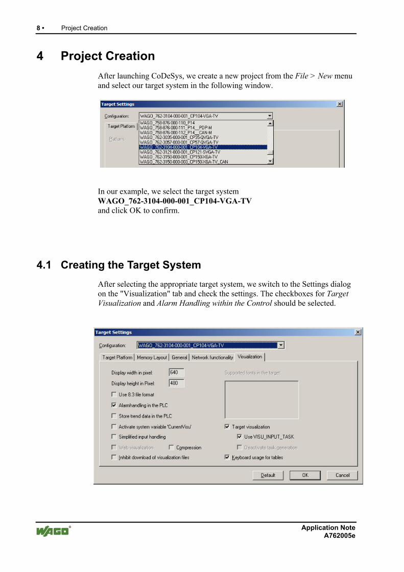
After launching CoDeSys, we create a new project from the File > New menu and select our target system in the following window.
In our example, we select the target system WAGO_762-3104-000-001_CP104-VGA-TV and click OK to confirm.
4.1 Creating the Target System
After selecting the appropriate target system, we switch to the Settings dialog on the "Visualization" tab and check the settings. The checkboxes for Target Visualization and Alarm Handling within the Control should be selected.
Project Creation • 9
Application Note A762005e
4.2 Creating a Simple PLC Program
After confirming the previous target system dialog (4.1), CoDeSys prompts us to create a module called PLC_PRG.
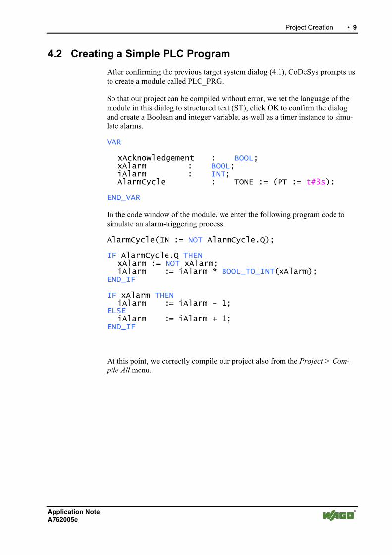
So that our project can be compiled without error, we set the language of the module in this dialog to structured text (ST), click OK to confirm the dialog and create a Boolean and integer variable, as well as a timer instance to simu-late alarms.
VAR
xAcknowledgement : BOOL; xAlarm : BOOL; iAlarm : INT; AlarmCycle : TONE := (PT := t#3s);
END_VAR
In the code window of the module, we enter the following program code to simulate an alarm-triggering process.
AlarmCycle(IN := NOT AlarmCycle.Q);
IF AlarmCycle.Q THEN xAlarm := NOT xAlarm; iAlarm := iAlarm * BOOL_TO_INT(xAlarm); END_IF
IF xAlarm THEN iAlarm := iAlarm - 1; ELSE iAlarm := iAlarm + 1; END_IF
At this point, we correctly compile our project also from the Project > Com-pile All menu.
10 • Project Creation
Application Note A762005e
4.3 Alarm Configuration
An alarm is triggered by a specific condition of a variable or expression and can be in the NORM or INTO or ACK or OUTOF states.
NORM -> Alarm is disabled INTO -> Alarm is enabled but not acknowledged ACK -> Alarm is enabled and has been acknowledged OUTOF-> Alarm is gone but not acknowledged yet
4.3.1 Definition of Alarm Classes
Each alarm belongs to an alarm class. The alarm class describes the actions triggered upon occurrence of an alarm and the states of the alarm that the user has to acknowledge. In addition, the alarm class describes the colors and bit-maps for representing the alarm in the alarm table.
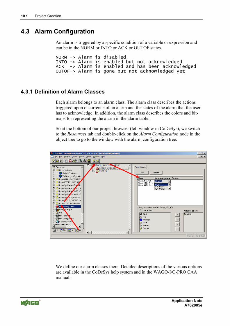
So at the bottom of our project browser (left window in CoDeSys), we switch to the Resources tab and double-click on the Alarm Configuration node in the object tree to go to the window with the alarm configuration tree.
We define our alarm classes there. Detailed descriptions of the various options are available in the CoDeSys help system and in the WAGO-I/O-PRO CAA manual.
Project Creation • 11
Application Note A762005e
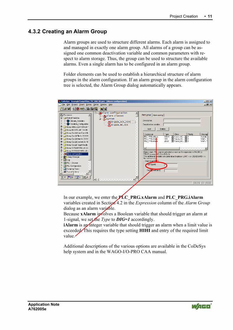
4.3.2 Creating an Alarm Group
Alarm groups are used to structure different alarms. Each alarm is assigned to and managed in exactly one alarm group. All alarms of a group can be as-signed one common deactivation variable and common parameters with re-spect to alarm storage. Thus, the group can be used to structure the available alarms. Even a single alarm has to be configured in an alarm group.
Folder elements can be used to establish a hierarchical structure of alarm groups in the alarm configuration. If an alarm group in the alarm configuration tree is selected, the Alarm Group dialog automatically appears.
In our example, we enter the PLC_PRG.xAlarm and PLC_PRG.iAlarm variables created in Section 4.2 in the Expression column of the Alarm Group dialog as an alarm variable. Because xAlarm involves a Boolean variable that should trigger an alarm at 1-signal, we set the Type to DIG=1 accordingly. iAlarm is an integer variable that should trigger an alarm when a limit value is exceeded. This requires the type setting HIHI and entry of the required limit value.
Additional descriptions of the various options are available in the CoDeSys help system and in the WAGO-I/O-PRO CAA manual.
12 • Project Creation
Application Note A762005e
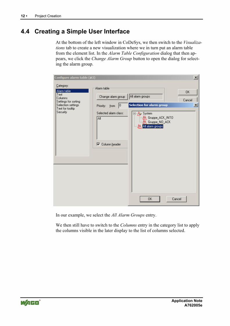
4.4 Creating a Simple User Interface
At the bottom of the left window in CoDeSys, we then switch to the Visualiza-tions tab to create a new visualization where we in turn put an alarm table from the element list. In the Alarm Table Configuration dialog that then ap-pears, we click the Change Alarm Group button to open the dialog for select-ing the alarm group.
In our example, we select the All Alarm Groups entry.
We then still have to switch to the Columns entry in the category list to apply the columns visible in the later display to the list of columns selected.
Project Creation • 13
Application Note A762005e
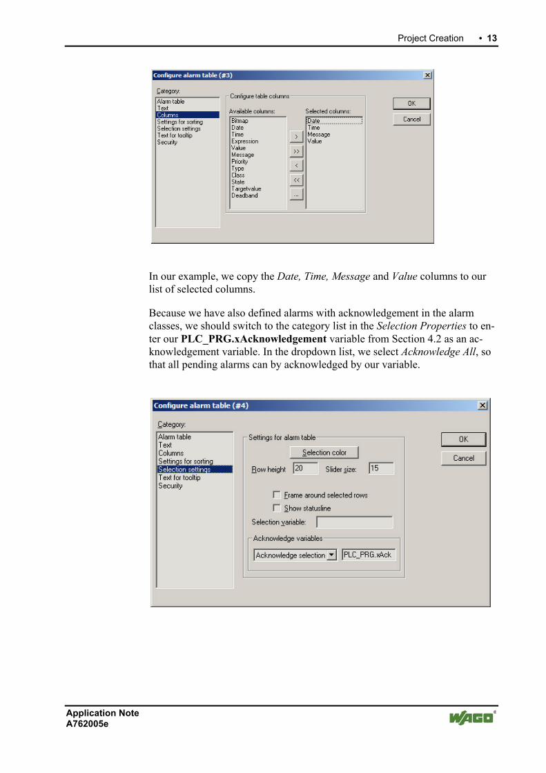
In our example, we copy the Date, Time, Message and Value columns to our list of selected columns.
Because we have also defined alarms with acknowledgement in the alarm classes, we should switch to the category list in the Selection Properties to en-ter our PLC_PRG.xAcknowledgement variable from Section 4.2 as an ac-knowledgement variable. In the dropdown list, we select Acknowledge All, so that all pending alarms can by acknowledged by our variable.
14 • Project Creation
Application Note A762005e
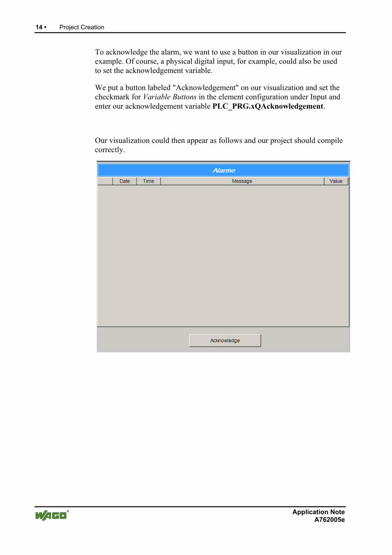
To acknowledge the alarm, we want to use a button in our visualization in our example. Of course, a physical digital input, for example, could also be used to set the acknowledgement variable.
We put a button labeled "Acknowledgement" on our visualization and set the checkmark for Variable Buttons in the element configuration under Input and enter our acknowledgement variable PLC_PRG.xQAcknowledgement.
Our visualization could then appear as follows and our project should compile correctly.
Project Creation • 15
Application Note A762005e
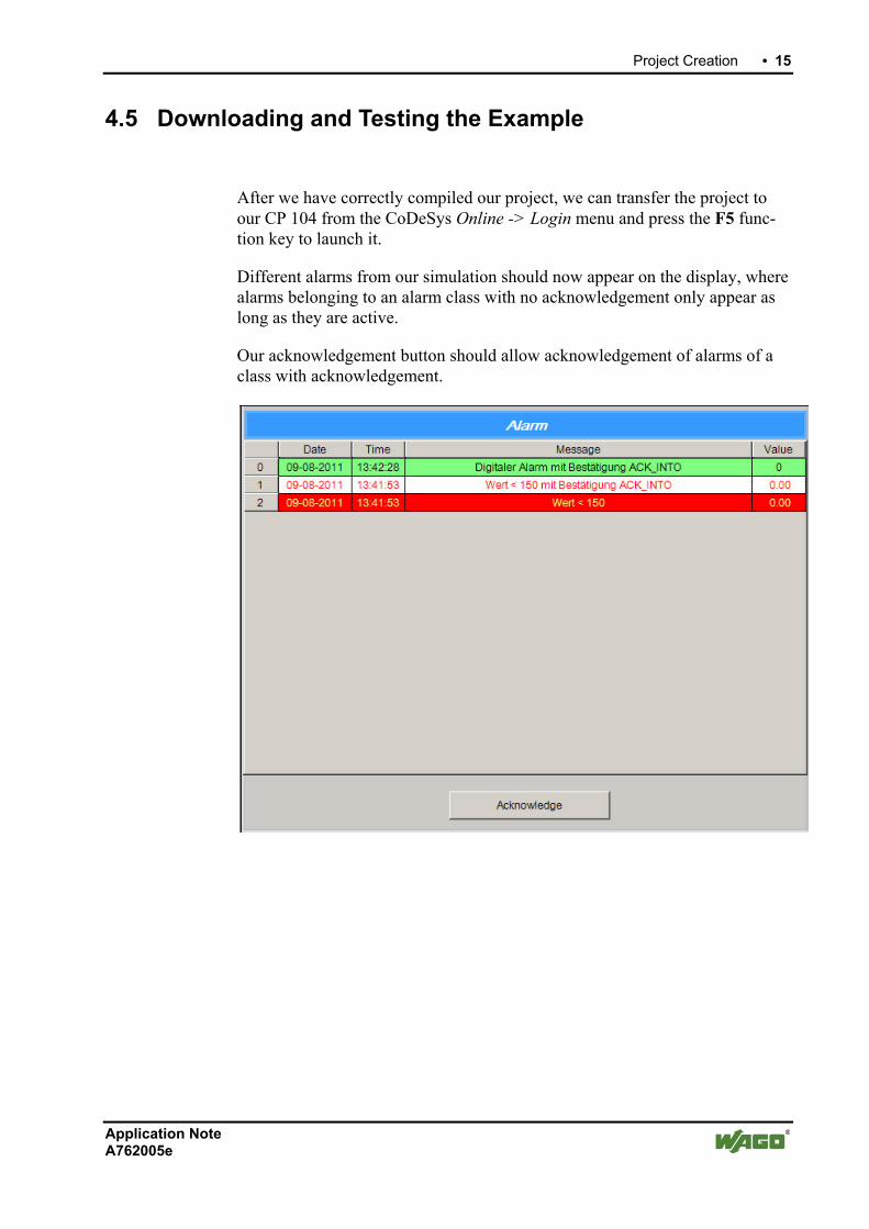
4.5 Downloading and Testing the Example
After we have correctly compiled our project, we can transfer the project to our CP 104 from the CoDeSys Online -> Login menu and press the F5 func-tion key to launch it.
Different alarms from our simulation should now appear on the display, where alarms belonging to an alarm class with no acknowledgement only appear as long as they are active.
Our acknowledgement button should allow acknowledgement of alarms of a class with acknowledgement.

WAGO Kontakttechnik GmbH & Co. KG PO Box 2880 • D-32385 Minden Hansastraße 27 • D-32423 Minden Phone: +49 (0) 571/8 87 – 0 Fax: +49 (0) 571/8 87 – 1 69 E-mail: [email protected] Internet: http://www.wago.com