Embed Size (px)
Citation preview
Manual
WAGO-I/O-SYSTEM 750
The WAGO KNX Concept
Version 1.0.6
2 General WAGO-I/O-SYSTEM 750 The WAGO KNX Concept Po
s: 1 /Alle Serien (Allgemeine Module)/Hinweise zur Dokumentation/Impressum für Gebäudeautomation @ 6\mod_1262949783214_21.doc @ 47761
General
© 2010 by WAGO Kontakttechnik GmbH & Co. KG All rights reserved.
WAGO Kontakttechnik GmbH & Co. KG
Hansastraße 27 D-32423 Minden
Phone: +49 (0) 571/8 87 – 0 Fax: +49 (0) 571/8 87 – 1 69
E-Mail: [email protected]
Web: http://www.wago.com
Technical Support
Phone: +49 (0) 571/8 87 – 7 77 Fax: +49 (0) 571/8 87 – 87 77
E-Mail: [email protected]
Every conceivable measure has been taken to ensure the accuracy and completeness of this documentation. However, as errors can never be fully excluded, we always appreciate any information or suggestions for improving the documentation.
E-Mail: [email protected]
We wish to point out that the software and hardware terms as well as the trademarks of companies used and/or mentioned in the present manual are generally protected by trademark or patent.
Po
s: 2 /Dokumentation allgemein/Gliederungselemente/---Seitenwechsel--- @ 3\mod_1221108045078_0.doc @ 21810
Manual Version 1.0.6
WAGO-I/O-SYSTEM 750 Table of Contents 3 The WAGO KNX Concept
s: 3 /Dokumentation allgemein/Verzeichnisse/Inhaltsverzeichnis - Überschrift 1 @ 3\mod_1219151230875_21.doc @ 21063 Po
Table of Contents
General ................................................................................................................... 2
Table of Contents................................................................................................... 3
1 Notes about this Documentation................................................................. 4
1.1 Copyright................................................................................................... 4 1.2 Symbols..................................................................................................... 4 1.3 Legal Bases ............................................................................................... 5 1.3.1 Use of the 750 Series in Compliance with Underlying Provisions ...... 5 1.3.2 Technical Condition of Specified Devices ........................................... 5
2 The WAGO KNX Concept.......................................................................... 6
2.1 KNX IP Controller 750-849...................................................................... 7 2.2 KNX/EIB/TP1 Module 753-646 ............................................................... 8 2.2.1 Router Mode......................................................................................... 9 2.2.2 Device Mode ...................................................................................... 10 2.3 Hardware Concept................................................................................... 11 2.4 Software Concept .................................................................................... 12 2.4.1 The IEC Application........................................................................... 13 2.4.2 ETS3, Product Database and PlugIn .................................................. 14 2.4.3 Web Visualization and Web-based Management............................... 16 2.4.3.1 Web Visualization ......................................................................... 16 2.4.3.2 Web-based Management ............................................................... 17 2.5 Application Examples ............................................................................. 18 2.5.1 KNXnet/IP Router .............................................................................. 18 2.5.2 KNX IP Application Controller + I/O Modules ................................. 19 2.5.3 KNX IP Application Controller + Router .......................................... 20 2.5.4 KNX IP Application Controller + I/O Modules + Router.................. 21 2.5.5 KNX IP Application Controller + Router + Additional KNX Module with Independent Line .......................................................... 22 2.5.6 KNX IP Application Controller + Router + KNX Module as Device in the Router Line................................................................... 23 2.5.7 Any Fieldbus Controller with KNX Module...................................... 24
3 Glossary ...................................................................................................... 26
List of Figures ...................................................................................................... 33
List of Tables........................................................................................................ 33
Po
s: 4 /Dokumentation allgemein/Gliederungselemente/---Seitenwechsel--- @ 3\mod_1221108045078_0.doc @ 21810
Manual Version 1.0.6
4 Notes about this Documentation WAGO-I/O-SYSTEM 750 The WAGO KNX Concept
s: 5 /Alle Serien (Allgemeine Module)/Überschriften für alle Serien/Hinweise zur Dokumentation - Überschrift 1 @ 4\mod_1237987661750_21.doc @ 29029 Po
1 Notes about this Documentation Po
s: 6 /Alle Serien (Allgemeine Module)/Hinweise zur Dokumentation/Urheberschutz ausführlich @ 4\mod_1235565145234_21.doc @ 27691
1.1 Copyright
This Manual, including all figures and illustrations, is copyright-protected. Any further use of this Manual by third parties that violate pertinent copyright provisions is prohibited. Reproduction, translation, electronic and phototech-nical filing/archiving (e.g., photocopying) as well as any amendments require the written consent of WAGO Kontakttechnik GmbH & Co. KG, Minden, Germany. Non-observance will involve the right to assert damage claims.
Po
s: 7 /Alle Serien (Allgemeine Module)/Hinweise zur Dokumentation/Symbole @ 3\mod_1217394197593_21.doc @ 21010
1.2 Symbols
Note Important Note! Indicates a potential malfunction which, if not avoided, however, will not result in damage to property.
Information Additional Information: Refers to additional information which is not an integral part of this documentation (e.g., the Internet).
Po
s: 8 /Dokumentation allgemein/Gliederungselemente/---Seitenwechsel--- @ 3\mod_1221108045078_0.doc @ 21810
Manual Version 1.0.6
WAGO-I/O-SYSTEM 750 Notes about this Documentation 5 The WAGO KNX Concept
s: 9 /Alle Serien (Allgemeine Module)/Überschriften für alle Serien/Rechtliche Grundlagen - Überschrift 2 @ 3\mod_1221060626343_21.doc @ 21726 Po
1.3 Legal Bases Po
s: 10 /Serie 750 (WAGO-I/O-SYSTEM)/Wichtige Erläuterungen/Bestimmungsgemäße Verwendung 750-xxxx @ 3\mod_1224064151234_21.doc @ 24070
1.3.1 Use of the 750 Series in Compliance with Underlying Provisions
Couplers, controllers and I/O modules found in the modular WAGO-I/O-SYSTEM 750 receive digital and analog signals from sensors and transmit them to the actuators or higher-level control systems. Using programmable controllers, the signals can also be (pre-)processed.
The components have been developed for use in an environment that meets the IP20 protection class criteria. Protection against finger injury and solid impurities up to 12.5 mm diameter is assured; protection against water damage is not ensured. Unless otherwise specified, operation of the components in wet and dusty environments is prohibited.
Appropriate housing (per 94/9/EG) is required when operating the WAGO-I/O-SYSTEM 750 in hazardous environments. Please note that a prototype test certificate must be obtained that confirms the correct installation of the system in a housing or switch cabinet.
Po
s: 11 /Alle Serien (Allgemeine Module)/Wichtige Erläuterungen/Technischer Zustand der Geräte @ 3\mod_1221060446109_21.doc @ 21723
1.3.2 Technical Condition of Specified Devices
The components to be supplied Ex Works, are equipped with hardware and software configurations, which meet the individual application requirements. Changes in hardware, software and firmware are permitted exclusively within the framework of the various alternatives that are documented in the specific manuals. WAGO Kontakttechnik GmbH & Co. KG will be exempted from any liability in case of changes in hardware or software as well as to non-compliant usage of components.
Please send your request for modified and new hardware or software configu-rations directly to WAGO Kontakttechnik GmbH & Co. KG.
Po
s: 12 /Dokumentation allgemein/Gliederungselemente/---Seitenwechsel--- @ 3\mod_1221108045078_0.doc @ 21810
Manual Version 1.0.6
6 The WAGO KNX Concept WAGO-I/O-SYSTEM 750 The WAGO KNX Concept
s: 13 /Serie 750 (WAGO-I/O-SYSTEM)/Feldbuskommunikation/KNX/KNX-Konzept @ 6\mod_1255599831265_21.doc @ 42940 Po
2 The WAGO KNX Concept
As the demand for flexible and convenient electrical installations increases, more emphasis is given to convenient functionality combined with least energy consumption. This results in the development of modern, resource-saving systems for the building automation, using common infrastructures and combining all functions of intelligent house and building technologies across the trades.
KNX is well established as a flexible bus system for building automation in this field. The KNX standard is based on the bus standards of the European Installation bus (EIB), BatiBUS and European Home Systems (EHS). It assures compatibility and interoperability of the various devices and systems by different manufacturers.
For the activation of the KNX devices and networks, a central tool exists in the Engineering-Tool-Software (ETS3) developed by the European-Installation-Bus-Association (EIBA, today "KNX-Association") in cooperation with software developers and KNX/EIB manufacturers.
The WAGO KNX products, controller and module, are – in many respects – an innovative development in the field of KNX.
• The KNX IP controller 750-849 is utilized in the KNX ETHERNET network as a flexible, freely programmable application controller.
• The KNX/EIB/TP1 module 753-646 (abbreviated KNX module) provides the interface between a two-wire TP1 network to the WAGO controllers, which are used as freely programmable application controllers on the TP1 network.
• The KNX module expands the KNX IP controller to a full-scale KNXnet/IP router. This router couples TP1 networks to IP networks and also provides the access to ETS3.
• The KNX IP controller contains two logical devices, of which one functions as application controller to be freely programmed. The other device becomes active when the KNX module is plugged and performs routing functions.
• The KNX module can be operated on all programmable fieldbus controllers of the Series 750, as they are relevant for building automation, and it assumes gateway functions (e.g., protocol transformation between KNX and LON).
Manual Version 1.0.6
WAGO-I/O-SYSTEM 750 The WAGO KNX Concept 7 The WAGO KNX Concept
2.1 KNX IP Controller 750-849
The KNX IP controller works on the hardware basis of the WAGO ETHERNET controller 750-841. Except for EtherNet/IP, the same protocols are used for the data transfer. In addition, the KNXnet/IP protocol is implemented. This protocol to the KNX standard combines the benefit of a high transmission rate of 10 to 100 Mbit via ETHERNET with the well known KNX procedures for commissioning and communication between several controllers in the network.
In the controller hardware, two independent KNX devices - KNX IP device and KNXnet/IP router - are located which will become active depending on the application. Both KNX IP devices use a common IP configuration and have a common IP address. The devices only differ in their port numbers.
The controller is set up and configured with the ETS3, the setup tool for KNX/EIB devices. In the ETS3, the WAGO product database is imported containing the WAGO ETS3 PlugIn which provides the configuration of the WAGO KNX devices. Depending on the device type, the ETS3 decides how the device is displayed in the network, how it communicates and how it must be configured for such communication. The principal task of the ETS3 PlugIn is the assignment of the variables used in the application, to KNX group addresses via which the communication in the TP1 network is conducted.
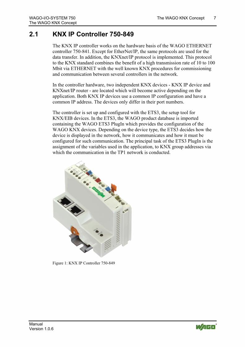
Figure 1: KNX IP Controller 750-849
Manual Version 1.0.6
8 The WAGO KNX Concept WAGO-I/O-SYSTEM 750 The WAGO KNX Concept
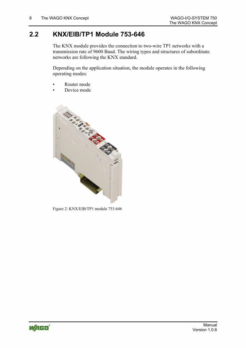
2.2 KNX/EIB/TP1 Module 753-646
The KNX module provides the connection to two-wire TP1 networks with a transmission rate of 9600 Baud. The wiring types and structures of subordinate networks are following the KNX standard.
Depending on the application situation, the module operates in the following operating modes:
• Router mode • Device mode
Figure 2: KNX/EIB/TP1 module 753-646
Manual Version 1.0.6
WAGO-I/O-SYSTEM 750 The WAGO KNX Concept 9 The WAGO KNX Concept
2.2.1 Router Mode
If KNX modules are operated on the KNX IP controller, the controller will automatically identify the first module of this type as a module with routing function. It does not matter how many non-KNX modules are plugged upstream.
With the first plugged KNX module, a KNX IP controller can be operated as KNXnet/IP router, without additional PLC program (see note). A connection is established between the KNX IP network of the controller and the TP1 network at the first KNX module. The network of the KNX module becomes a subordinate line of the KNX IP network, creating a routing between twisted-pair and ETHERNET.
The router enables the direct access of the ETS3 – which is connected to the IP network of the controller – to the TP1 network, via the controller itself and the
Note Router function can be deactivated in the Web-Based Management system! You have the option of disabling the router functionality in the web-based management system on the "KNX" page. In this case, all connected KNX modules including the first one are operated in device mode. It is assumed in the following that the routing function is enabled (default setting).
Note Routing is possible only via the first plugged KNX module! Routing is possible only via the first plugged KNX module. The routing function is independent from whether an IEC application is running on the controller. All other KNX modules plugged to the controller can be addressed only via the IEC-61131-3 application.
Note IEC application is only required for the logic processing within the IP controller! The PLC program in the controller is an IEC application, created with the programming tool WAGO-I/O-PRO CAA in conformance with IEC-61131-3. An IEC application is only required for the logic processing within the IP controller.
Manual Version 1.0.6
10 The WAGO KNX Concept WAGO-I/O-SYSTEM 750 The WAGO KNX Concept
2.2.2 Device Mode
If the KNX module operates as second or further module of this type on a WAGO KNX IP controller, it will work in device mode. In this case, it is connected to the controller via the IEC-61131-3 application. The module also operates in device mode when it is operated at any location in another WAGO controller.
Communication objects are programmed in the IEC-61131-3 application. They represent a specific data format (e.g. DPT_Switch as 1 bit value) and are connected to actions such as "Switch light" or "Operate blinds". The communication objects, of which each device owns at least one, are mapped in the ETS3.
Via the linkage of these objects to the KNX group addresses, a connection is established between the IEC application of the controller and the network of the module. Depending on the number of plugged KNX modules, two or more independent TP1 networks can be interconnected. The commissioning of the controller with the assignment of communication objects to group addresses is performed using the ETS3 PlugIn.
If the module is operating on WAGO controllers, gateway functionalities to other fieldbus systems, such as LON, PROFIBUS etc. can be realized. For the information of the subordinate TP1 network, as mapped in the process image, a specific address processing is required, which cannot be performed in the couplers or superordinate controllers. For this reason, an application of the KNX module on WAGO couplers is not possible.
Note Note the compatibility of the KNX module with other WAGO fieldbus controllers! The KNX module can be operated on all programmable fieldbus controllers used in building automation. Exceptions hereto are shown in the documentation to the KNX/EIB/TP1 module 753-646. The documentation is available on the internet site http://www.wago.com under Documentation WAGO-I/O-SYSTEM 753 Special modules 753-646 KNX/EIB/TP1 module - device mode
Manual Version 1.0.6
WAGO-I/O-SYSTEM 750 The WAGO KNX Concept 11 The WAGO KNX Concept
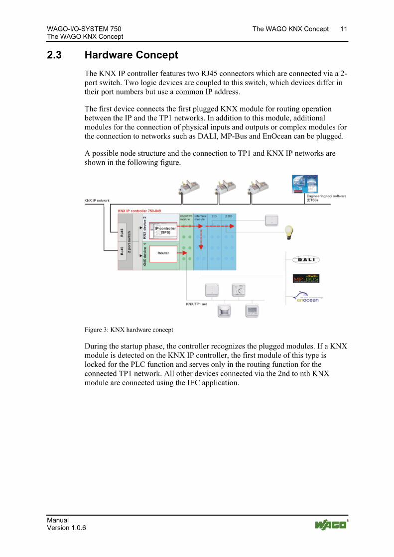
2.3 Hardware Concept
The KNX IP controller features two RJ45 connectors which are connected via a 2-port switch. Two logic devices are coupled to this switch, which devices differ in their port numbers but use a common IP address.
The first device connects the first plugged KNX module for routing operation between the IP and the TP1 networks. In addition to this module, additional modules for the connection of physical inputs and outputs or complex modules for the connection to networks such as DALI, MP-Bus and EnOcean can be plugged.
A possible node structure and the connection to TP1 and KNX IP networks are shown in the following figure.
Figure 3: KNX hardware concept
During the startup phase, the controller recognizes the plugged modules. If a KNX module is detected on the KNX IP controller, the first module of this type is locked for the PLC function and serves only in the routing function for the connected TP1 network. All other devices connected via the 2nd to nth KNX module are connected using the IEC application.
Manual Version 1.0.6
12 The WAGO KNX Concept WAGO-I/O-SYSTEM 750 The WAGO KNX Concept
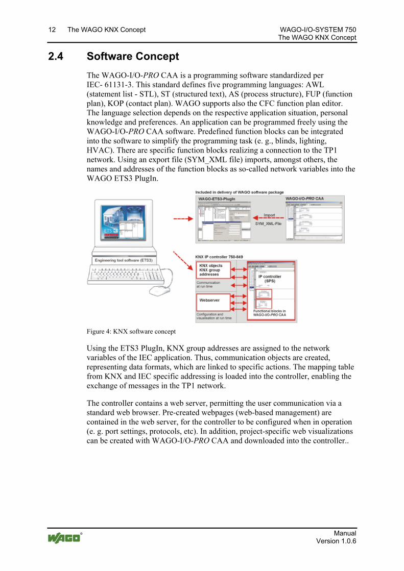
2.4 Software Concept
The WAGO-I/O-PRO CAA is a programming software standardized per IEC- 61131-3. This standard defines five programming languages: AWL (statement list - STL), ST (structured text), AS (process structure), FUP (function plan), KOP (contact plan). WAGO supports also the CFC function plan editor. The language selection depends on the respective application situation, personal knowledge and preferences. An application can be programmed freely using the WAGO-I/O-PRO CAA software. Predefined function blocks can be integrated into the software to simplify the programming task (e. g., blinds, lighting, HVAC). There are specific function blocks realizing a connection to the TP1 network. Using an export file (SYM_XML file) imports, amongst others, the names and addresses of the function blocks as so-called network variables into the WAGO ETS3 PlugIn.
Figure 4: KNX software concept
Using the ETS3 PlugIn, KNX group addresses are assigned to the network variables of the IEC application. Thus, communication objects are created, representing data formats, which are linked to specific actions. The mapping table from KNX and IEC specific addressing is loaded into the controller, enabling the exchange of messages in the TP1 network.
The controller contains a web server, permitting the user communication via a standard web browser. Pre-created webpages (web-based management) are contained in the web server, for the controller to be configured when in operation (e. g. port settings, protocols, etc). In addition, project-specific web visualizations can be created with WAGO-I/O-PRO CAA and downloaded into the controller..
Manual Version 1.0.6
WAGO-I/O-SYSTEM 750 The WAGO KNX Concept 13 The WAGO KNX Concept
2.4.1 The IEC Application
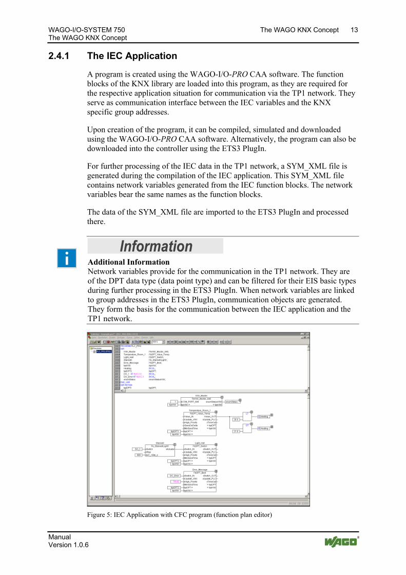
A program is created using the WAGO-I/O-PRO CAA software. The function blocks of the KNX library are loaded into this program, as they are required for the respective application situation for communication via the TP1 network. They serve as communication interface between the IEC variables and the KNX specific group addresses.
Upon creation of the program, it can be compiled, simulated and downloaded using the WAGO-I/O-PRO CAA software. Alternatively, the program can also be downloaded into the controller using the ETS3 PlugIn.
For further processing of the IEC data in the TP1 network, a SYM_XML file is generated during the compilation of the IEC application. This SYM_XML file contains network variables generated from the IEC function blocks. The network variables bear the same names as the function blocks.
The data of the SYM_XML file are imported to the ETS3 PlugIn and processed there.
Information Additional Information Network variables provide for the communication in the TP1 network. They are of the DPT data type (data point type) and can be filtered for their EIS basic types during further processing in the ETS3 PlugIn. When network variables are linked to group addresses in the ETS3 PlugIn, communication objects are generated. They form the basis for the communication between the IEC application and the TP1 network.
Figure 5: IEC Application with CFC program (function plan editor)
Manual Version 1.0.6
14 The WAGO KNX Concept WAGO-I/O-SYSTEM 750 The WAGO KNX Concept
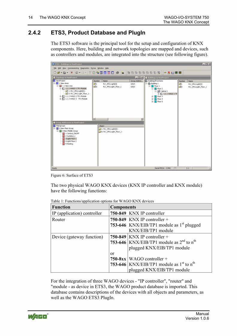
2.4.2 ETS3, Product Database and PlugIn
The ETS3 software is the principal tool for the setup and configuration of KNX components. Here, building and network topologies are mapped and devices, such as controllers and modules, are integrated into the structure (see following figure).
Figure 6: Surface of ETS3
The two physical WAGO KNX devices (KNX IP controller and KNX module) have the following functions:
Table 1: Functions/application options for WAGO KNX devices
Function Components IP (application) controller 750-849 KNX IP controller Router 750-849
753-646KNX IP controller + KNX/EIB/TP1 module as 1st plugged KNX/EIB/TP1 module
Device (gateway function) 750-849753-646 or 750-8xx753-646
KNX IP controller + KNX/EIB/TP1 module as 2nd to nth plugged KNX/EIB/TP1 module WAGO controller + KNX/EIB/TP1 module as 1st to nth plugged KNX/EIB/TP1 module
For the integration of three WAGO devices - "IP controller", "router" and "module - as device in ETS3, the WAGO product database is imported. This database contains descriptions of the devices with all objects and parameters, as well as the WAGO ETS3 PlugIn.
Manual Version 1.0.6
WAGO-I/O-SYSTEM 750 The WAGO KNX Concept 15 The WAGO KNX Concept
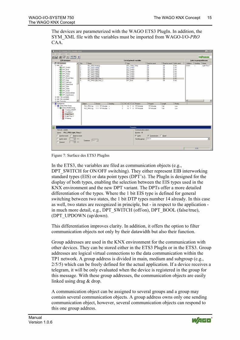
The devices are parameterized with the WAGO ETS3 PlugIn. In addition, the SYM_XML file with the variables must be imported from WAGO-I/O-PRO CAA.
Figure 7: Surface des ETS3 PlugIns
In the ETS3, the variables are filed as communication objects (e.g., DPT_SWITCH for ON/OFF switching). They either represent EIB interworking standard types (EIS) or data point types (DPT’s). The PlugIn is designed for the display of both types, enabling the selection between the EIS types used in the KNX environment and the new DPT variant. The DPTs offer a more detailed differentiation of the types. Where the 1 bit EIS type is defined for general switching between two states, the 1 bit DTP types number 14 already. In this case as well, two states are recognized in principle, but - in respect to the application - in much more detail, e.g., DPT_SWITCH (off/on), DPT_BOOL (false/true), (DPT_UPDOWN (up/down).
This differentiation improves clarity. In addition, it offers the option to filter communication objects not only by their datawidth but also their function.
Group addresses are used in the KNX environment for the communication with other devices. They can be stored either in the ETS3 PlugIn or in the ETS3. Group addresses are logical virtual connections to the data communication within the TP1 network. A group address is divided in main, medium and subgroup (e.g., 2/5/5) which can be freely defined for the actual application. If a device receives a telegram, it will be only evaluated when the device is registered in the group for this message. With these group addresses, the communication objects are easily linked using drag & drop.
A communication object can be assigned to several groups and a group may contain several communication objects. A group address owns only one sending communication object, however, several communication objects can respond to this one group address.
Manual Version 1.0.6
16 The WAGO KNX Concept WAGO-I/O-SYSTEM 750 The WAGO KNX Concept
In addition to the device configuration, the KNX group addresses are loaded into the address table of the controller. The controller is thus prepared for communication in the TP1 network.
2.4.3 Web Visualization and Web-based Management
Two options are available for making changes to the HTML pages.
2.4.3.1 Web Visualization
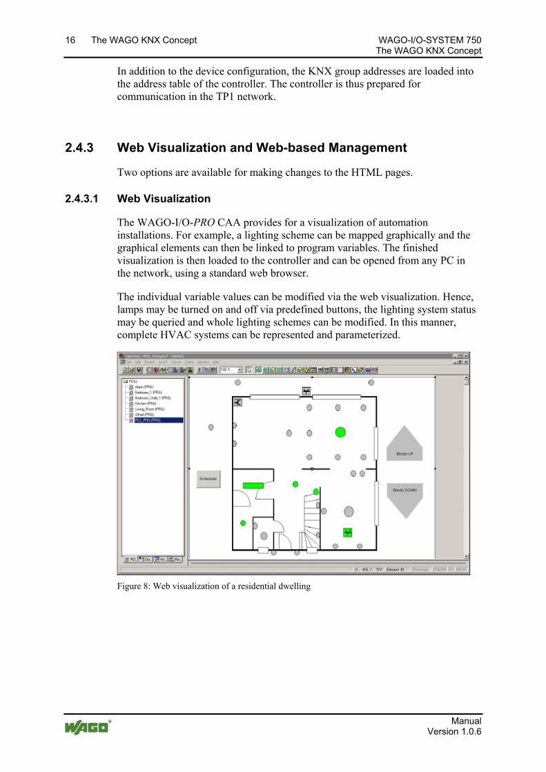
The WAGO-I/O-PRO CAA provides for a visualization of automation installations. For example, a lighting scheme can be mapped graphically and the graphical elements can then be linked to program variables. The finished visualization is then loaded to the controller and can be opened from any PC in the network, using a standard web browser.
The individual variable values can be modified via the web visualization. Hence, lamps may be turned on and off via predefined buttons, the lighting system status may be queried and whole lighting schemes can be modified. In this manner, complete HVAC systems can be represented and parameterized.
Figure 8: Web visualization of a residential dwelling
Manual Version 1.0.6
WAGO-I/O-SYSTEM 750 The WAGO KNX Concept 17 The WAGO KNX Concept
2.4.3.2 Web-based Management
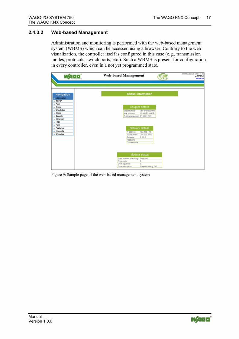
Administration and monitoring is performed with the web-based management system (WBMS) which can be accessed using a browser. Contrary to the web visualization, the controller itself is configured in this case (e.g., transmission modes, protocols, switch ports, etc.). Such a WBMS is present for configuration in every controller, even in a not yet programmed state..
Figure 9: Sample page of the web-based management system
Manual Version 1.0.6
18 The WAGO KNX Concept WAGO-I/O-SYSTEM 750 The WAGO KNX Concept
2.5 Application Examples
The KNX IP controller 750-849 and the KNX/EIB/TP1 module 753-646 can be utilized in many ways and combined with other WAGO components. The KNX IP controller 750-849 features two internal devices: an application controller (IP controller with IEC program) and a router which becomes active when a KNX module is plugged in.
The following illustrates the main application options.
2.5.1 KNXnet/IP Router
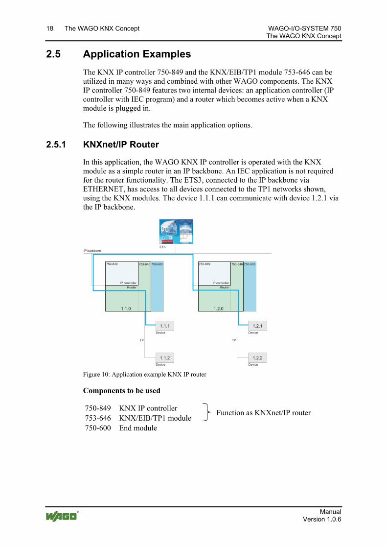
In this application, the WAGO KNX IP controller is operated with the KNX module as a simple router in an IP backbone. An IEC application is not required for the router functionality. The ETS3, connected to the IP backbone via ETHERNET, has access to all devices connected to the TP1 networks shown, using the KNX modules. The device 1.1.1 can communicate with device 1.2.1 via the IP backbone.
753-646 750-600750-849 750-600750-849
ETS
TP TP
1.1.1
1.1.2
1.2.1
1.2.2
Router
1.1.0
753-646
Router
1.2.0
Device
Device
Device
Device
IP backbone
IP controller IP controller
Figure 10: Application example KNX IP router
Components to be used
750-849 KNX IP controller 753-646 KNX/EIB/TP1 module
Function as KNXnet/IP router
750-600 End module
Manual Version 1.0.6
WAGO-I/O-SYSTEM 750 The WAGO KNX Concept 19 The WAGO KNX Concept
2.5.2 KNX IP Application Controller + I/O Modules
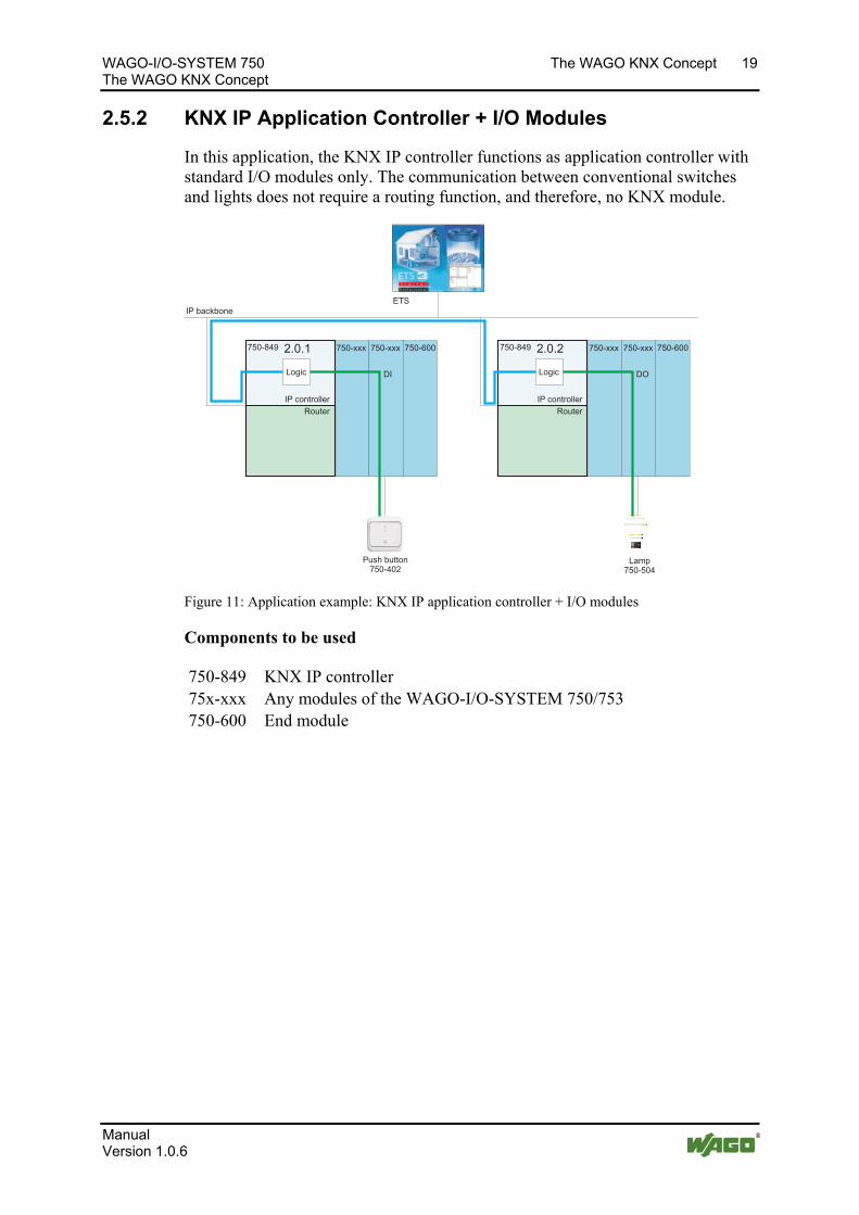
In this application, the KNX IP controller functions as application controller with standard I/O modules only. The communication between conventional switches and lights does not require a routing function, and therefore, no KNX module.
750-xxx 750-600
ETS
750-xxx 750-xxx 750-600750-xxx
DI DO
750-849 2.0.2750-849 2.0.1
Push button750-402
Lamp750-504
Logic
IP backbone
IP controller
Logic
Router Router
IP controller
Figure 11: Application example: KNX IP application controller + I/O modules
Components to be used
750-849 KNX IP controller 75x-xxx Any modules of the WAGO-I/O-SYSTEM 750/753 750-600 End module
Manual Version 1.0.6
20 The WAGO KNX Concept WAGO-I/O-SYSTEM 750 The WAGO KNX Concept
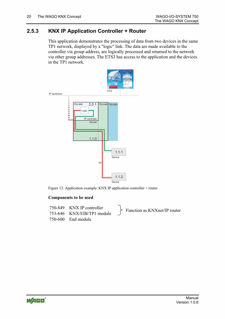
2.5.3 KNX IP Application Controller + Router
This application demonstrates the processing of data from two devices in the same TP1 network, displayed by a "logic" link. The data are made available to the controller via group address, are logically processed and returned to the network via other group addresses. The ETS3 has access to the application and the devices in the TP1 network.
753-646 750-600750-849
ETS
TP
Router
2.0.1
1.1.1
1.1.2
753-646
Router
1.1.0
IP backbone
Device
Device
Logic
IP controller
Figure 12: Application example: KNX IP application controller + router
Components to be used
750-849 KNX IP controller 753-646 KNX/EIB/TP1 module
Function as KNXnet/IP router
750-600 End module
Manual Version 1.0.6
WAGO-I/O-SYSTEM 750 The WAGO KNX Concept 21 The WAGO KNX Concept
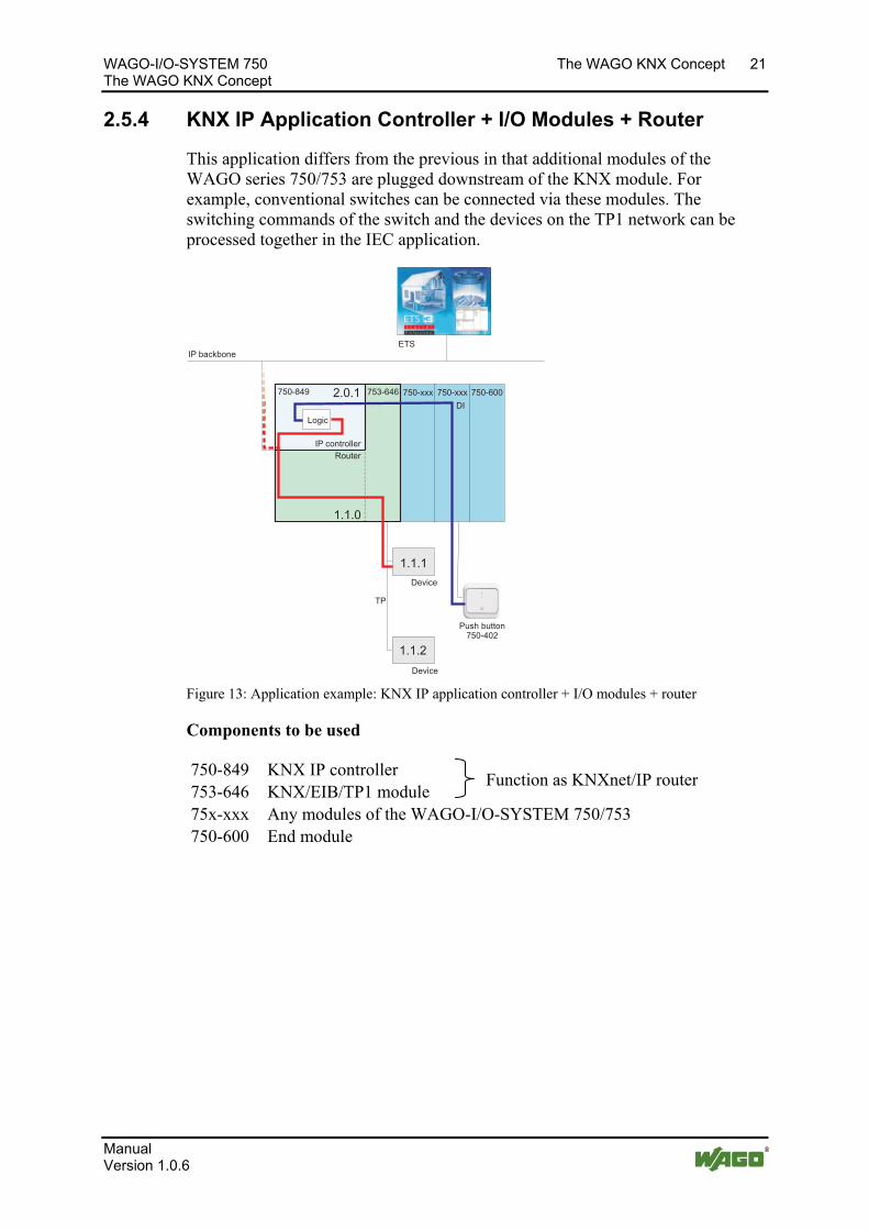
2.5.4 KNX IP Application Controller + I/O Modules + Router
This application differs from the previous in that additional modules of the WAGO series 750/753 are plugged downstream of the KNX module. For example, conventional switches can be connected via these modules. The switching commands of the switch and the devices on the TP1 network can be processed together in the IEC application.
Router
753-646 750-xxx750-849
ETS
TP
750-xxx 750-6002.0.1
1.1.1
1.1.2
DI
753-646
Router
1.1.0
IP controller
IP backbone
Device
Device
Logic
Push button750-402
Figure 13: Application example: KNX IP application controller + I/O modules + router
Components to be used
750-849 KNX IP controller 753-646 KNX/EIB/TP1 module
Function as KNXnet/IP router
75x-xxx Any modules of the WAGO-I/O-SYSTEM 750/753 750-600 End module
Manual Version 1.0.6
22 The WAGO KNX Concept WAGO-I/O-SYSTEM 750 The WAGO KNX Concept
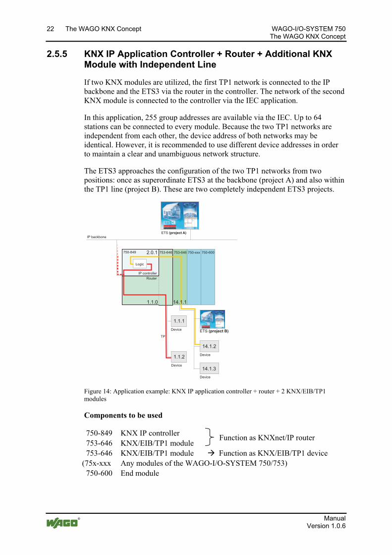
2.5.5 KNX IP Application Controller + Router + Additional KNX Module with Independent Line
If two KNX modules are utilized, the first TP1 network is connected to the IP backbone and the ETS3 via the router in the controller. The network of the second KNX module is connected to the controller via the IEC application.
In this application, 255 group addresses are available via the IEC. Up to 64 stations can be connected to every module. Because the two TP1 networks are independent from each other, the device address of both networks may be identical. However, it is recommended to use different device addresses in order to maintain a clear and unambiguous network structure.
The ETS3 approaches the configuration of the two TP1 networks from two positions: once as superordinate ETS3 at the backbone (project A) and also within the TP1 line (project B). These are two completely independent ETS3 projects.
753-646 753-646750-849
TP
750-xxx 750-600
Router
2.0.1
1.1.1
1.1.2
14.1.2
14.1.3
753-646
Router
1.1.0 14.1.1
IP backbone
ETS (project A)
Device
Device
Device
Device
ETS (project B)
IP controller
Logic
Figure 14: Application example: KNX IP application controller + router + 2 KNX/EIB/TP1 modules
Components to be used
750-849 KNX IP controller 753-646 KNX/EIB/TP1 module
Function as KNXnet/IP router
753-646 KNX/EIB/TP1 module Function as KNX/EIB/TP1 device (75x-xxx Any modules of the WAGO-I/O-SYSTEM 750/753) 750-600 End module
Manual Version 1.0.6
WAGO-I/O-SYSTEM 750 The WAGO KNX Concept 23 The WAGO KNX Concept
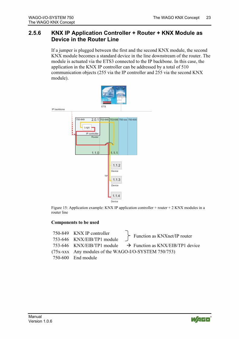
2.5.6 KNX IP Application Controller + Router + KNX Module as Device in the Router Line
If a jumper is plugged between the first and the second KNX module, the second KNX module becomes a standard device in the line downstream of the router. The module is actuated via the ETS3 connected to the IP backbone. In this case, the application in the KNX IP controller can be addressed by a total of 510 communication objects (255 via the IP controller and 255 via the second KNX module).
753-646 753-646750-849
ETS
TP
750-xxx 750-600
Router
2.0.1
1.1.2
1.1.3
1.1.4
753-646
Router
1.1.0 1.1.1
IP backbone
Device
Device
Device
IP controller
Logic
Figure 15: Application example: KNX IP application controller + router + 2 KNX modules in a router line
Components to be used
750-849 KNX IP controller 753-646 KNX/EIB/TP1 module
Function as KNXnet/IP router
753-646 KNX/EIB/TP1 module Function as KNX/EIB/TP1 device (75x-xxx Any modules of the WAGO-I/O-SYSTEM 750/753) 750-600 End module
Manual Version 1.0.6
24 The WAGO KNX Concept WAGO-I/O-SYSTEM 750 The WAGO KNX Concept
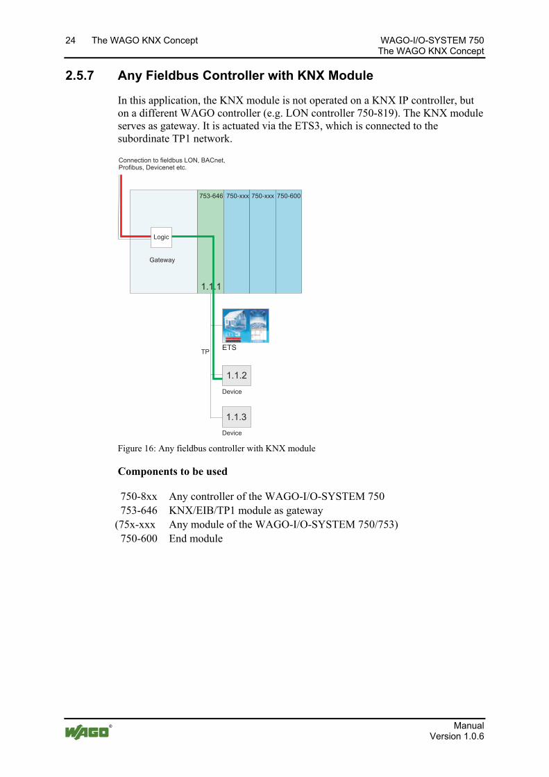
2.5.7 Any Fieldbus Controller with KNX Module
In this application, the KNX module is not operated on a KNX IP controller, but on a different WAGO controller (e.g. LON controller 750-819). The KNX module serves as gateway. It is actuated via the ETS3, which is connected to the subordinate TP1 network.
753-646 750-xxx
TP
750-xxx 750-600
ETS
Gateway
1.1.2
1.1.3
1.1.1
Connection to fieldbus LON, BACnet,Profibus, Devicenet etc.
Logic
Device
Device
Figure 16: Any fieldbus controller with KNX module
Components to be used
750-8xx Any controller of the WAGO-I/O-SYSTEM 750 753-646 KNX/EIB/TP1 module as gateway (75x-xxx Any module of the WAGO-I/O-SYSTEM 750/753) 750-600 End module
Po
s: 14 /Dokumentation allgemein/Gliederungselemente/---Seitenwechsel--- @ 3\mod_1221108045078_0.doc @ 21810
Manual Version 1.0.6
WAGO-I/O-SYSTEM 750 The WAGO KNX Concept 25 The WAGO KNX Concept
Information Additional Information Further documentation can be found on the following internet pages:
KNX/EIB/TP1 Module 753-646 http://www.wago.com Service Documentation WAGO-I/O-SYSTEM 753 Special Modules
WAGO ETS3 PlugIn http://www.wago.com Service Documentation WAGO-I/O-SYSTEM 753 Special Modules 753-646 Additional Information
Libraries for Building Automation (Description of function blocks for EIB/KNX) http://www.wago.com Service Downloads Building Automation
Manual Version 1.0.6
26 Glossary WAGO-I/O-SYSTEM 750 The WAGO KNX Concept
Po
s: 15 /Alle Serien (Allgemeine Module)/Überschriften für alle Serien/Glossar - Überschrift 1 @ 7\mod_1265811387961_21.doc @ 50272
3 Glossary Pos: 16 /Serie 750 (WAGO-I/O-SYSTEM)/Glossar/Glossar - KNX-Konzept @ 7\mod_1265975290004_21.doc @ 50580
A
Associations Associations are assignments of KNX group addresses to communication objects. The KNX/EIB/TP1 Module supports 254 associations.
C
Communication Object Communication objects are generated from KNX specific function blocks which are programmed in the IEC application and imported as network variables into the ETS3. In the ETS3, the network variables are linked to KNX group addresses. The communication objects are the result of this link. They represent certain data formats and are linked to actions which tell a device how to react. One communication object may belong to several groups and one group may contain several communication objects. A group address is required by the communication object only for data sending, but communication objects may receive data under several group addresses. A device owns at least one communication object. The format of a communication object is defined as either data point type (DPT) or EIB interworking standard (EIS).
D
Device Mode If a KNX/EIB/TP1 module 753-646 is operated as second or subsequent module of this type on a KNX IP controller, or if it is plugged into another WAGO controller at any location, the module works in device mode. Module and controller then communicate via the IEC-61131-3 application of the controller. If the KNX/EIB/TP1 operates however as first module of this type on a KNX IP controller it operates in router mode.
DPT (Data Point Type) The Data Point Type describes the property/function of a communication object and is assigned to the same via the ETS3. For example: a data point type "Boolean" may be of the data type 1.001 DPT_switch. Its data width is 1 bit. With
Manual Version 1.0.6
WAGO-I/O-SYSTEM 750 Glossary 27 The WAGO KNX Concept
this, it codes the states "on"/"off". A total of 14 different DPT's exist for the data type "Boolean".
In addition to the data point types, there are also EIS types (EIB Interworking Standard Types). This, however, is the older definition with less detailed representation than the DPT's.
E
EIS (EIB Interworking Standard) The EIS types define properties/functions of KNX objects. They are standardized by the EIBA/KNX Association as EIS 1 to EIS 15 and assure interoperability and manufacturer-independency. EIS types are increasingly replaced by the data point types structured in more detail.
ETHERNET Specifies a Local Area Network (LAN), which was developed by Xerox, Intel and DEC in the 70’s. The bus access process takes place according to the CSMA/CD method.
ETS3 (Engineering Tool Software) The ETS3 is a manufacturer-independent tool for the installation, commissioning, design, documentation, diagnostics and maintenance of KNX devices. The ETS3 defines which bus users, lines and ranges execute which function at which location.
ETS3-PlugIn Manufacturers supply their products together with a product database and possibly a specific ETS3 plugIn. This plugIn is linked into the ETS3. With WAGO products, one of the functions of the ETS3 plug is the creation of a connection between data points of the programmed application and the KNX group addresses.
Manual Version 1.0.6
28 Glossary WAGO-I/O-SYSTEM 750 The WAGO KNX Concept
F
Fieldbus The fieldbus is a dedicated bus for the serial transmission of information. Fieldbusses connect sensors, actuators and controls from the field level to the management level. Numerous different fieldbusses have been developed for various purposes. For example, the LON and KNX fieldbusses are mostly used in building automation, whereas CANbus and Interbus are mostly applied in the automotive industry.
Function Blocks/Function Modules Function blocks are used in programming and are stored in libraries for repeated utilization. A function block is a structured module, which has a name and contains input and output variables, but also local variables. The values of the local variables can be stored locally for the interim. The input and output variables are stored in the controller memory. The respective memory sectors of the function blocks are exported as network variable when the IEC program is compiled, and they are imported to the ETS3, as a SYM_ZML file, together with other data. The network variables bear the same names as the function blocks in which they originate. In the ETS3, the network variables are then linked with KNX group addresses and create the basis for the communication between the IP and the TP1 network.
G
Gateway Device for connecting two different networks, performs the translation between differing protocols.
Group Address (Logical Address in TP1 Network) The group address is a logical address serving in the communication in the KNX network. Net users will evaluate messages only when they belong to the group addressed with the group address. They are displayed in two or three levels as main, medium, where applicable, and sub group with the corresponding value ranges [0...13], [0...7] and [0...255], e.g., 3/4/12. The group classification is freely selectable but should conform to rules, e.g., main group for main functions, medium group for levels/buildings, sub group for detailed information. Communication objects and group addresses are assigned within the ETS3 plugIn. The group address assumes the length format of the communication object. Subsequently, this group address can only be allocated to communication objects with the same length.
Manual Version 1.0.6
WAGO-I/O-SYSTEM 750 Glossary 29 The WAGO KNX Concept
I
IEC 61131-3 International standard for modern systems with PLC functionality, created in 1993. Based on a structured software model, it defines a series of powerful programming languages to be utilized for different automation tasks. AWL (statement list - STL), ST (structured text), AS (process structure), FUP (function plan), KOP (contact plan).
IP (Internet Protocol) The internet protocol is a network protocol transmitting data in the net, packet-oriented, connection-free and unacknowledged. It is based on the switching layer of the ISO/OSI model. Stations are defined by their IP addresses.
K
KNX KNX is the only open standard worldwide for all applications in the field of house and building automation, from lighting and blind control to security systems, HVAC installations, monitoring and alarm systems, water supply, energy management and counters, up to household appliances, audio, video and much more. KNX is the only house and building technology standard with one single setup tool (ETS3), independent of manufacturer or product, containing a complete set of transmission media (twisted pair, power line, radio, connections to ETHERNET (KNXnet/IP) and a complete set of configuration modes (system mode, simple and automatic mode). KNX is recognized as European Standard (CENELEC EN 50090 and CEN EN 13321-1) and as International Standard (ISO/IEC 14543-3). As such, it is based on the 15 years of experience with its predecessors EIB, EHS and BatiBUS. More than 100 member organizations worldwide offer nearly 7,000 KNX-certified product groups in their catalogs.
KNX Association The KNX association is the founder and owner of the KNX technology. The association has signed partnership agreements with more than 21,000 installation companies in 70 countries (http://www.konnex.org).
KNX IP KNX IP denotes the use of the Internet Protocol (IP) as the only KNX medium.
KNX IP Controller The programmable fieldbus controller 750-849 (abbreviated as PFC) is a combination of two logic devices with a 2-port switch. The KNX IP controller can be operated directly in an IP network as a stand-alone, freely programmable KNX IP device, using a RJ-45 connector. In combination with a KNX/EIB/TP1 module, the controller is expanded to a full-size KNXnet/IP router and enables the coupling between an IP network and a two-wire TP1 network.
Manual Version 1.0.6
30 Glossary WAGO-I/O-SYSTEM 750 The WAGO KNX Concept
KNX IP Device KNX IP Device describes a KNX end device using the Internet Protocol (IP) as the only KNX medium.
KNX/EIB/TP1 Module The KNX/EIB/TP1 module 753-646 serves in the connection of two-wire TP1 networks to all WAGO controllers, except for the CANopen and the MODBUS controllers. The KNX module may be operated in device mode or router mode. The operating mode is set by the KNX IP controller and also depends on the position of the KNX module on the controller.
KNX Function Block see Function Blocks/Function Modules
KNXnet/IP Protocol Series The KNXnet/IP protocol corresponds to the already standardized EIBnet/IP protocol series. KNXnet/IP is the integration of the KNX protocol implementations on top of Internet Protocol (IP) networks. Via the KNXnet/IP protocol, a direct connection between two KNX IP devices is established. Because the KNXnet/IP protocol is based on the ETHERNET, it permits connection across large distances (e.g. via the internet). This can mean very high speeds to one or several remote networks.
KNXnet/IP Router If the 753-646 KNX/EIB/TP1 module operates as the first KNX module of this type on a KNX IP controller, it operates in router mode. The controller and the module together are designated as a KNXnet/IP router. The routing function enables the module’s TP1 network to be linked to the rapid medium IP. In addition, the KNXnet/IP router is also used as a line and range coupler that contains filter tables and contributes to a flattening out of the hierarchies in the network.
L
Line (KNX) A line connects up to 64 bus users in one TP1 network. If more users are present, additional lines are created. The lines are connected to the main line each using a line coupler. These main lines form ranges which are connected to the backbone via range couplers. Lines may also be connected directly to the backbone. A line coupler is identified in the network by its user number "0" in the physical address (e.g., 2.6.0).
LON (Local Operating Network) LON is used as fieldbus in the building automation. It was developed 1990 by Echelon and enables, as does KNX, the communication between different devices, independent of the manufacturer and active application.
Manual Version 1.0.6
WAGO-I/O-SYSTEM 750 Glossary 31 The WAGO KNX Concept
N
Network Variables Network variables reference each a memory sector in the controller, where the input and output data of the KNX-specific function blocks are stored. The network variables are exported into a SYM-XML file when the IEC application is compiled, and they are copied to the ETS3 for further processing. In the ETS3, the network variables are then linked to the KNX group addresses and create the basis for the communication between the IP and the TP1 network.
P
Parameterizing Parameterizing is defined as the assignment and storage of setup and configuration data as they are required for the execution of predefined functions.
Port Number The port number, in conjunction with the IP address, is the unique connection point between two processes (applications).
R
Range A range is a summary of maximum 15 lines. These are connected to a main line via a line coupler. Up to 15 ranges can be interconnected with range couplers. They are positioned at range line and have the physical addresses x.0.0 (e.g., 2.0.0).
RJ-45 Connector The RJ-45 connector is also known as Western connector. This connector creates the connection of two network controllers via a twisted-pair cable.
Router Connecting neighboring subnets, the router operate with addresses and protocols of the third ISO/OSI layer. As this layer is hardware independent, the routers allow transition to another transmission medium. To transmit a message the router evaluates the logical address (source and destination address) and finds the best path if there are several possibilities. Routers can be operated as repeaters or bridges.
Router Mode If the KNX/EIB/TP1 module 753-646 is operated on a KNX IP controller 750-849, the module operates in router mode enabling a data exchange between the TP1
Manual Version 1.0.6
32 Glossary WAGO-I/O-SYSTEM 750 The WAGO KNX Concept
network of the module and IP network of the controller. Thus, even devices of different TP1 networks can communicate with each other, if they are connected via an IP backbone.
S
Switch Switches are comparable to bridges, but with several outputs. Each output uses the full ETHERNET bandwidth. A switch switches a virtual connection between an input port and an output port for data transmission. Switches learn which nodes are connected and filter the information transmitted over the network accordingly.
W
WAGO-I/O-PRO CAA (CoDeSys Automation Alliance) Unified programming environment, programming tool by WAGO Kontakttechnik GmbH& Co. KG for the generation of a control program as per IEC-61131-3 for all programmable fieldbus controllers (PFC). Provides for the creation, testing, debugging and startup of the program. The WAGO-I/O-PRO CAA consists of the basic tool "CoDeSys 2.3 CAA" and the target files with WAGO specific drivers.
Po
s: 17 /Dokumentation allgemein/Gliederungselemente/---Seitenwechsel--- @ 3\mod_1221108045078_0.doc @ 21810
Pos: 18.1 /Dokumentation allgemein/Gliederungselemente/---Seitenwechsel--- @ 3\mod_1221108045078_0.doc @ 21810
Manual Version 1.0.6
WAGO-I/O-SYSTEM 750 List of Figures 33 The WAGO KNX Concept
Manual Version 1.0.6
s: 18.2 /Dokumentation allgemein/Verzeichnisse/Abbildungsverzeichnis - Überschrift 1 @ 3\mod_1219222916765_21.doc @ 21080 Po
List of Figures
Figure 1: KNX IP Controller 750-849 .................................................................... 7 Figure 2: KNX/EIB/TP1 module 753-646 .............................................................. 8 Figure 3: KNX hardware concept ......................................................................... 11 Figure 4: KNX software concept........................................................................... 12 Figure 5: IEC Application with CFC program (function plan editor)................... 13 Figure 6: Surface of ETS3..................................................................................... 14 Figure 7: Surface des ETS3 PlugIns...................................................................... 15 Figure 8: Web visualization of a residential dwelling........................................... 16 Figure 9: Sample page of the web-based management system ............................. 17 Figure 10: Application example KNX IP router ................................................... 18 Figure 11: Application example: KNX IP application controller + I/O modules . 19 Figure 12: Application example: KNX IP application controller + router............ 20 Figure 13: Application example: KNX IP application controller + I/O modules +
router ............................................................................................................ 21 Figure 14: Application example: KNX IP application controller + router + 2
KNX/EIB/TP1 modules ............................................................................... 22 Figure 15: Application example: KNX IP application controller + router + 2 KNX
modules in a router line................................................................................ 23 Figure 16: Any fieldbus controller with KNX module ......................................... 24
Po
s: 18.3 /Dokumentation allgemein/Gliederungselemente/---Seitenwechsel--- @ 3\mod_1221108045078_0.doc @ 21810
s: 18.4 /Dokumentation allgemein/Verzeichnisse/Tabellenverzeichnis - Überschrift 1 @ 3\mod_1219222958703_21.doc @ 21084 Po
List of Tables
Table 1: Functions/application options for WAGO KNX devices........................ 14
WAGO Kontakttechnik GmbH & Co. KG Postfach 2880 • D-32385 Minden Hansastraße 27 • D-32423 Minden Phone: +49/5 71/8 87 – 0 Fax: +49/5 71/8 87 – 1 69 E-Mail: [email protected] Internet: http://www.wago.com