Embed Size (px)
Citation preview
Cooling concepts for CanPAKTM* package
Published by Infineon Technologies AG
http://www.infineon.com
* CanPAKTM
products use DirectFET® technology licensed from International Rectifier Corporation. DirectFETTM
is a trademark of International Rectifier Corporation
IMM PSD LV Peinhopf Wolfgang
Cooling concepts for CanPAKTM *
package
2/17
Edition 28.02.2011
Published by Infineon Technologies Austria AG 9500 Villach, Austria
© 2011 Infineon Technologies Austria AG All Rights Reserved.
Legal Disclaimer
The information given in this document shall in no event be regarded as a guarantee of conditions or characteristics. With respect to any examples or hints given herein, any typical values stated herein and/or any information regarding the application of the device, Infineon Technologies hereby disclaims any and all warranties and liabilities of any kind, including without limitation, warranties of non-infringement of intellectual property rights of any third party.
Information
For further information on technology, delivery terms and conditions and prices, please contact the nearest Infineon Technologies Office (www.infineon.com).
Warnings
Due to technical requirements, components may contain dangerous substances. For information on the types in question, please contact the nearest Infineon Technologies Office.
Infineon Technologies components may be used in life-support devices or systems only with the express written approval of Infineon Technologies, if a failure of such components can reasonably be expected to cause the failure of that life-support device or system or to affect the safety or effectiveness of that device or system. Life support devices or systems are intended to be implanted in the human body or to support and/or maintain and sustain and/or protect human life. If they fail, it is reasonable to assume that the health of the u
Revision History
Actual Release: Rev.1.0
February 2011
Cooling concepts for CanPAKTM *
package
3/17
1 Introduction ..................................................................................................... 4
2 CanPAKTM package ........................................................................................ 4
3 Thermal resistance ......................................................................................... 5
4 CanPAKTM – Double sided cooling package .................................................. 6
4.1 Heatsink ................................................................................................... 7
4.2 Thermal interface materials (TIM’s) ......................................................... 8
4.3 Board attachment .................................................................................... 9
5 Thermal measurements and simulation ......................................................... 9
6 Summary ...................................................................................................... 14
7 Appendix ...................................................................................................... 14
Cooling concepts for CanPAKTM *
package
4/17
1 Introduction Cooling capability is the major disadvantage for SMD based power electronics. However, SMD based systems can’t be avoided when it comes to high efficiency. The CanPAK
TM package is a
package with a very low thermal resistance to the top and bottom side of the package. This allows using efficient cooling concepts and thus solves the issue of limited cooling capability in SMD systems. This document gives an overview of different cooling concepts and also provides thermal measurement and simulation results to see the improvement in thermal performance by employing such new concepts.
2 CanPAKTM
package CanPAK
TM is a surface mount semiconductor technology designed for board mounted power
applications. It optimizes elements of packaging to improve the thermal performance. CanPAKTM
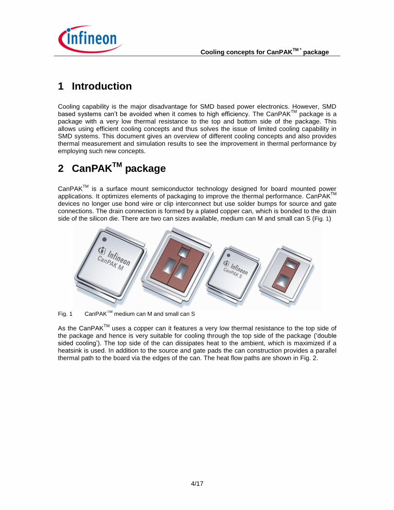
devices no longer use bond wire or clip interconnect but use solder bumps for source and gate connections. The drain connection is formed by a plated copper can, which is bonded to the drain side of the silicon die. There are two can sizes available, medium can M and small can S (Fig. 1)
Fig. 1 CanPAK
TM medium can M and small can S
As the CanPAK
TM uses a copper can it features a very low thermal resistance to the top side of
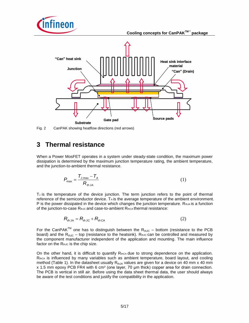
the package and hence is very suitable for cooling through the top side of the package (‘double sided cooling’). The top side of the can dissipates heat to the ambient, which is maximized if a heatsink is used. In addition to the source and gate pads the can construction provides a parallel thermal path to the board via the edges of the can. The heat flow paths are shown in Fig. 2.
Cooling concepts for CanPAKTM *
package
5/17
“Can” heat sink
Junction
Heat sink interface
material
“Can” (Drain)
SubstrateGate pad Source pads
“Can” heat sink
Junction
Heat sink interface
material
“Can” (Drain)
SubstrateGate pad Source pads
Fig. 2 CanPAK showing heatflow directions (red arrows)
3 Thermal resistance When a Power MosFET operates in a system under steady-state condition, the maximum power dissipation is determined by the maximum junction temperature rating, the ambient temperature, and the junction-to-ambient thermal resistance.
JA
max,
max
th
AJ
R
TTP
(1)
TJ is the temperature of the device junction. The term junction refers to the point of thermal reference of the semiconductor device. TA is the average temperature of the ambient environment. P is the power dissipated in the device which changes the junction temperature. RthJA is a function of the junction-to-case RthJC and case-to-ambient RthCA thermal resistance:
CA JC JA ththth RRR (2)
For the CanPAK
TM one has to distinguish between the RthJC – bottom (resistance to the PCB
board) and the RthJC – top (resistance to the heatsink). RthJC can be controlled and measured by the component manufacturer independent of the application and mounting. The main influence factor on the RthJC is the chip size. On the other hand, it is difficult to quantify RthCA due to strong dependence on the application. RthCA is influenced by many variables such as ambient temperature, board layout, and cooling method (Table 1). In the datasheet usually RthJA values are given for a device on 40 mm x 40 mm x 1.5 mm epoxy PCB FR4 with 6 cm² (one layer, 70 μm thick) copper area for drain connection. The PCB is vertical in still air. Before using the data sheet thermal data, the user should always be aware of the test conditions and justify the compatibility in the application.
Cooling concepts for CanPAKTM *
package
6/17
Table 1 Influence factors RthJC, RthCA
RthJC (product variables) RthCA (application variables)
Leadframe size & material Mounting pad size, shape and location
Die size Placement of mounting pad
Die attach material PCB size & material
Mold compound size & material Use of heatsink
Amount of thermal vias
Traces length & width
Adjacent heat sources
Air flow rate and volume of air
Ambient temperature, etc.
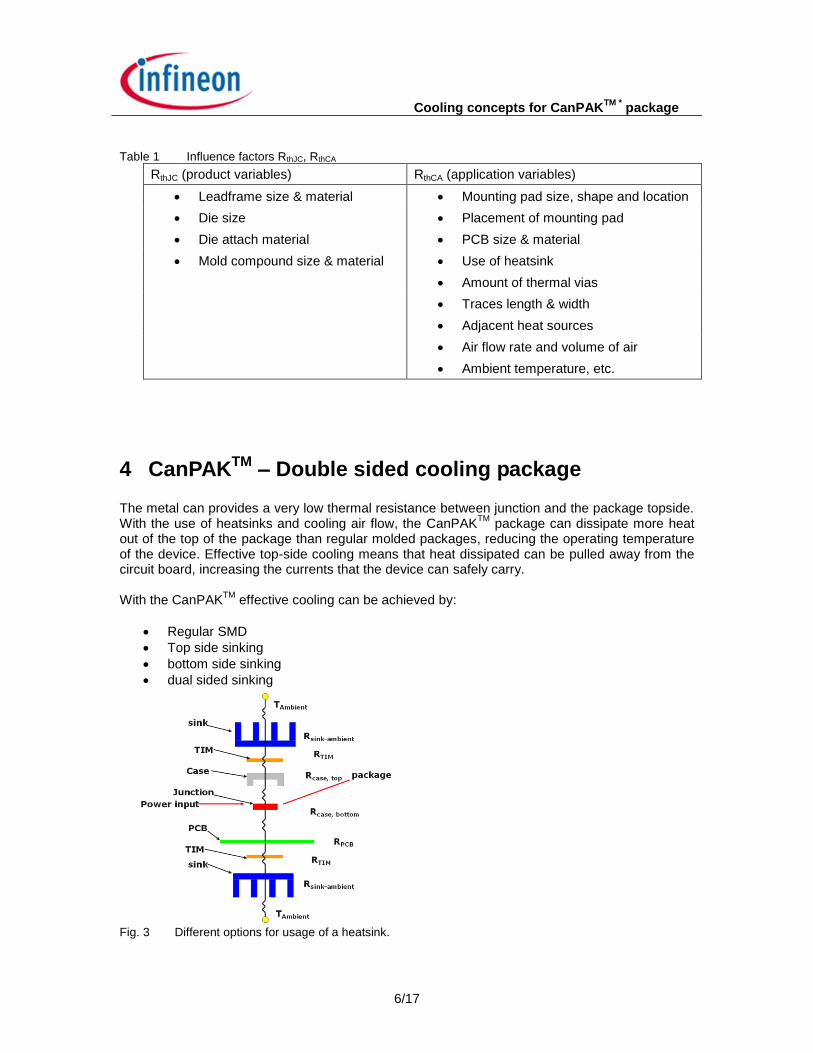
4 CanPAKTM
– Double sided cooling package The metal can provides a very low thermal resistance between junction and the package topside. With the use of heatsinks and cooling air flow, the CanPAK
TM package can dissipate more heat
out of the top of the package than regular molded packages, reducing the operating temperature of the device. Effective top-side cooling means that heat dissipated can be pulled away from the circuit board, increasing the currents that the device can safely carry.
With the CanPAK
TM effective cooling can be achieved by:
Regular SMD
Top side sinking
bottom side sinking
dual sided sinking
Fig. 3 Different options for usage of a heatsink.
Cooling concepts for CanPAKTM *
package
7/17
When using a heatsink three points have to be considered (Fig. 4) - heatsink - thermal interface material (TIM) - board attachment of heatsink
Fig. 4 Using a heatsink (heatsink, thermal interface material (TIM) and board attachment)
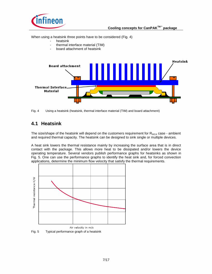
4.1 Heatsink The size/shape of the heatsink will depend on the customers requirement for RthCA case - ambient and required thermal capacity. The heatsink can be designed to sink single or multiple devices. A heat sink lowers the thermal resistance mainly by increasing the surface area that is in direct contact with the package. This allows more heat to be dissipated and/or lowers the device operating temperature. Several vendors publish performance graphs for heatsinks as shown in Fig. 5. One can use the performance graphs to identify the heat sink and, for forced convection applications, determine the minimum flow velocity that satisfy the thermal requirements.
Fig. 5 Typical performance graph of a heatsink
Cooling concepts for CanPAKTM *
package
8/17
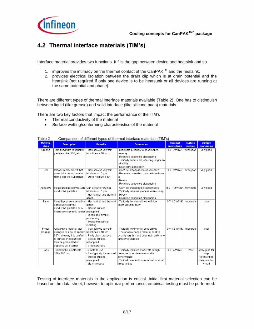
4.2 Thermal interface materials (TIM’s) Interface material provides two functions. It fills the gap between device and heatsink and so
1. improves the intimacy on the thermal contact of the CanPAKTM
and the heatsink. 2. provides electrical isolation between the drain clip which is at drain potential and the
heatsink (not required if only one device is to be heatsunk or all devices are running at the same potential and phase).
There are different types of thermal interface materials available (Table 2). One has to distinguish between liquid (like grease) and solid interface (like silicone pads) materials There are two key factors that impact the performance of the TIM’s
Thermal conductivity of the material
Surface wetting/conforming characteristics of the material Table 2 Comparison of different types of thermal interface materials (TIM’s)
Testing of interface materials in the application is critical. Initial first material selection can be based on the data sheet, however to optimize performance, empirical testing must be performed.
Cooling concepts for CanPAKTM *
package
9/17
4.3 Board attachment In the majority of cases the method of attachment is a compression fit of the heatsink onto the device. This is either achieved by screw mounting of the heatsink or through the use of a clip to affix the heatsink to the board. In both cases the interface material is sandwiched between the heatsink and the board.
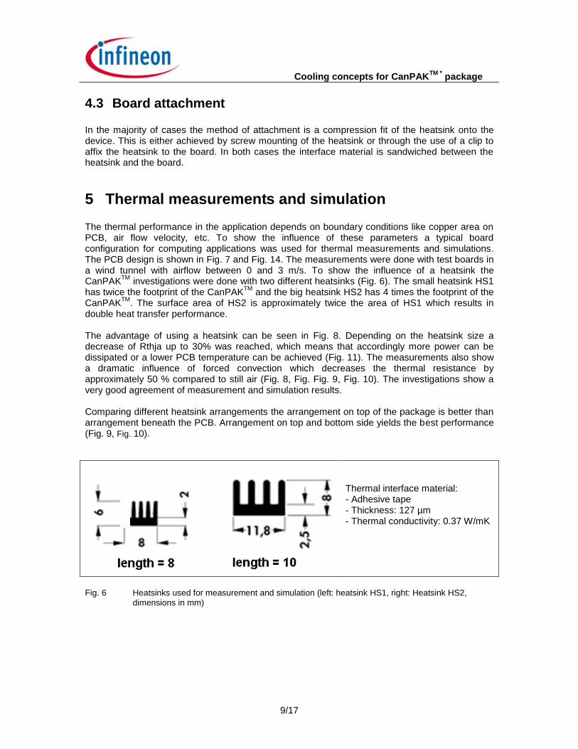
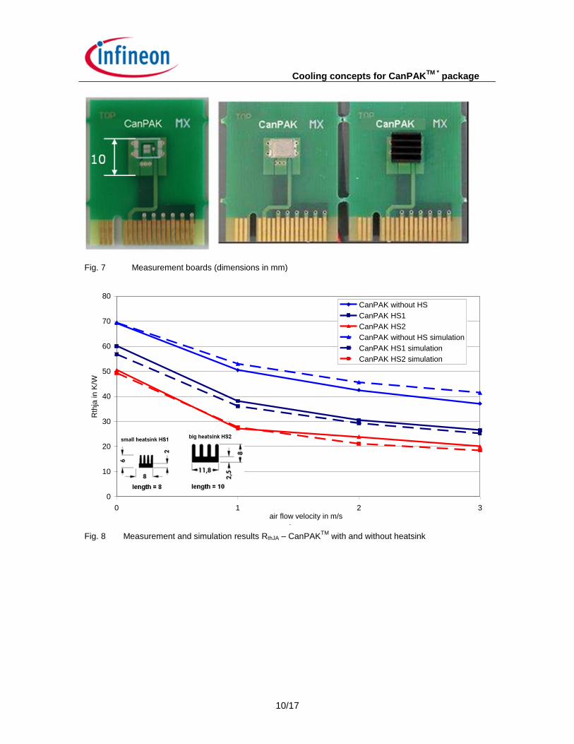
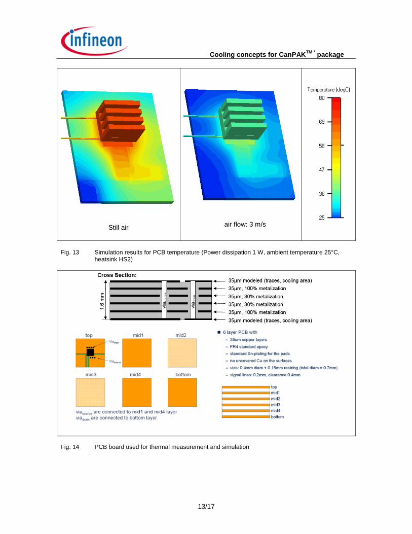
5 Thermal measurements and simulation The thermal performance in the application depends on boundary conditions like copper area on PCB, air flow velocity, etc. To show the influence of these parameters a typical board configuration for computing applications was used for thermal measurements and simulations. The PCB design is shown in Fig. 7 and Fig. 14. The measurements were done with test boards in a wind tunnel with airflow between 0 and 3 m/s. To show the influence of a heatsink the CanPAK
TM investigations were done with two different heatsinks (Fig. 6). The small heatsink HS1
has twice the footprint of the CanPAKTM
and the big heatsink HS2 has 4 times the footprint of the CanPAK
TM. The surface area of HS2 is approximately twice the area of HS1 which results in
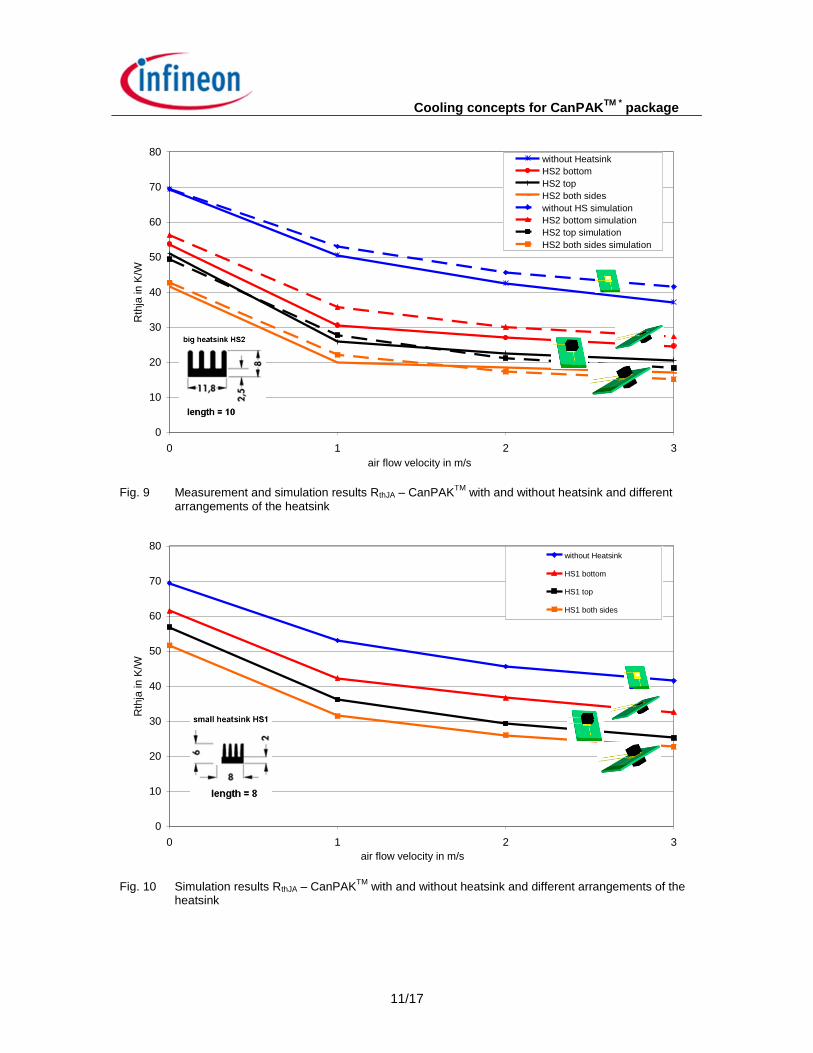
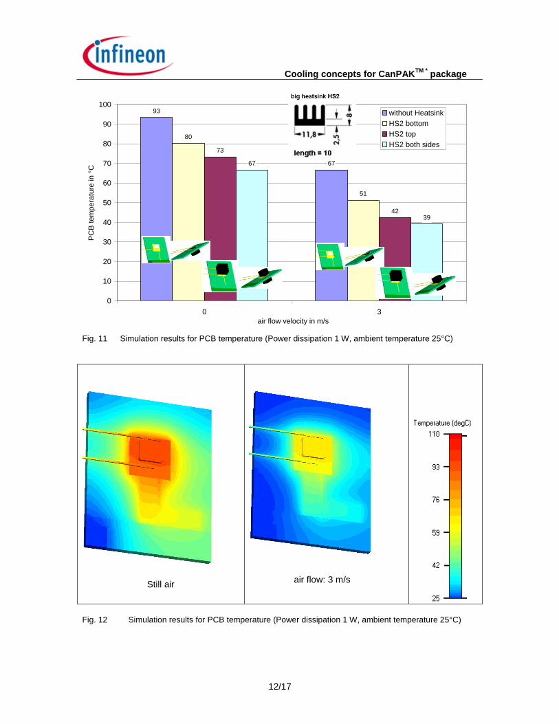
double heat transfer performance. The advantage of using a heatsink can be seen in Fig. 8. Depending on the heatsink size a decrease of Rthja up to 30% was reached, which means that accordingly more power can be dissipated or a lower PCB temperature can be achieved (Fig. 11). The measurements also show a dramatic influence of forced convection which decreases the thermal resistance by approximately 50 % compared to still air (Fig. 8, Fig. Fig. 9, Fig. 10). The investigations show a very good agreement of measurement and simulation results. Comparing different heatsink arrangements the arrangement on top of the package is better than arrangement beneath the PCB. Arrangement on top and bottom side yields the best performance (Fig. 9, Fig. 10).
Thermal interface material: - Adhesive tape - Thickness: 127 µm - Thermal conductivity: 0.37 W/mK
Fig. 6 Heatsinks used for measurement and simulation (left: heatsink HS1, right: Heatsink HS2,
dimensions in mm)
Cooling concepts for CanPAKTM *
package
10/17
Fig. 7
Measurement boards (dimensions in mm)
0
10
20
30
40
50
60
70
80
0 1 2 3
wind speed in m/s
Rth
ja in
K/W
CanPAK without HS
CanPAK HS1
CanPAK HS2
CanPAK without HS simulation
CanPAK HS1 simulation
CanPAK HS2 simulation
Fig. 8 Measurement and simulation results RthJA – CanPAK
TM with and without heatsink
air flow velocity in m/s
Cooling concepts for CanPAKTM *
package
11/17
0
10
20
30
40
50
60
70
80
0 1 2 3
wind speed in m/s
Rth
ja in K
/W
without Heatsink
HS2 bottom
HS2 top
HS2 both sides
without HS simulation
HS2 bottom simulation
HS2 top simulation
HS2 both sides simulation
Fig. 9 Measurement and simulation results RthJA – CanPAK
TM with and without heatsink and different
arrangements of the heatsink
0
10
20
30
40
50
60
70
80
0 1 2 3
wind speed in m/s
Rth
ja in K
/W
without Heatsink
HS1 bottom
HS1 top
HS1 both sides
Fig. 10 Simulation results RthJA – CanPAK
TM with and without heatsink and different arrangements of the
heatsink
air flow velocity in m/s
air flow velocity in m/s
Cooling concepts for CanPAKTM *
package
12/17
93
67
80
51
73
42
67
39
0
10
20
30
40
50
60
70
80
90
100
0 3
wind speed in m/s
PC
B tem
pera
ture
in °
C
without Heatsink
HS2 bottom
HS2 top
HS2 both sides
Fig. 11 Simulation results for PCB temperature (Power dissipation 1 W, ambient temperature 25°C)
Still air
Wind speed: 3 m/s
Fig. 12 Simulation results for PCB temperature (Power dissipation 1 W, ambient temperature 25°C)
air flow velocity in m/s
air flow: 3 m/s
Cooling concepts for CanPAKTM *
package
13/17
Still air
Wind speed: 3 m/s
Fig. 13 Simulation results for PCB temperature (Power dissipation 1 W, ambient temperature 25°C,
heatsink HS2)
Fig. 14
PCB board used for thermal measurement and simulation
air flow: 3 m/s
Cooling concepts for CanPAKTM *
package
14/17
6 Summary This document outlines different cooling concepts for the CanPAK
TM package. Measurements
and simulations show a significant thermal improvement by using heatsinks and by forced convection. There is a good agreement between measurement and simulation results. In the appendix a simple method for an analytic calculation of the thermal resistance is shown.
7 Appendix Analytic calculation of the thermal resistance Rth_JA The thermal resistance Rth_JA can be calculated using a one dimensional model. As heat is transferred via the top and bottom side the thermal resistance to the top and bottom side have to be considered. The Rth_JA can be calculated using the formula for parallel connection of thermal resistances:
bottomthtopth
bottomthtopth
JAthRR
RRR
__
__
_
(3)
ambient - junction resistance thermal
side bottom resistance thermal
side-top resistance thermal
_
_
_
JAth
bottomth
topth
R
R
R
Case 1: Without heatsink
topradconvthtopJCthtopth RRR ______ (4)
PCBthbottomJCthbottomth RRR ____ (5)
PCB resistance thermal
)(datasheet side bottom resistance package thermalR
side-top package resistance radiation and convection
)(datasheet side-bottom resistance package thermal
_
tomth__JC_bot
___
__
PCBth
topradconvth
topJCth
R
R
R
Case 1: With heatsink In case of using a heatsink the Rth_top resistance has to be calculated differently.
kheatthTIMthtopJCthtopth RRRR sin_____ (6)
heatsink resistance thermal
(TIM) material interface thermal resistance thermalR
sin_
tomth__JC_bot
kheatthR
Cooling concepts for CanPAKTM *
package
15/17
Calculation Example 1:
package CanPAK M
Heatsink no
Boundary condition Natural convection
topradconvthtopJCthtopth RRR ______
value) (datasheet /4.1__ WKR topJCth
The Rth_conv_rad_top can be calculated using equation (8). As a rule of thumb the heat transfer coefficient for convection and radiation is about 10 W/m²K. The contact area is calculated by using the package drawing in the datasheet (~ 30.9 mm²)
value) (datasheet0.1
8.32404.32394.1
4.32399.3010
1
__
_
22
___
WKR
WKR
WK
mmKm
WR
bottomJCth
topth
topradconvth
As the Rth_PCB is difficult to calculate with a one-dimensional model this value is estimated based on the measurement results.
WKR
WKR
bottomth
PCBth
71700.1
70
_
_
The RthJA is calculated using equation (3)
WKR JAth 5.69_
The ratio of power dissipation top side and overall dissipation gives:
%21008.3240
5.69100100
__
_
_
topth
JAth
R
R
P
sidetopP
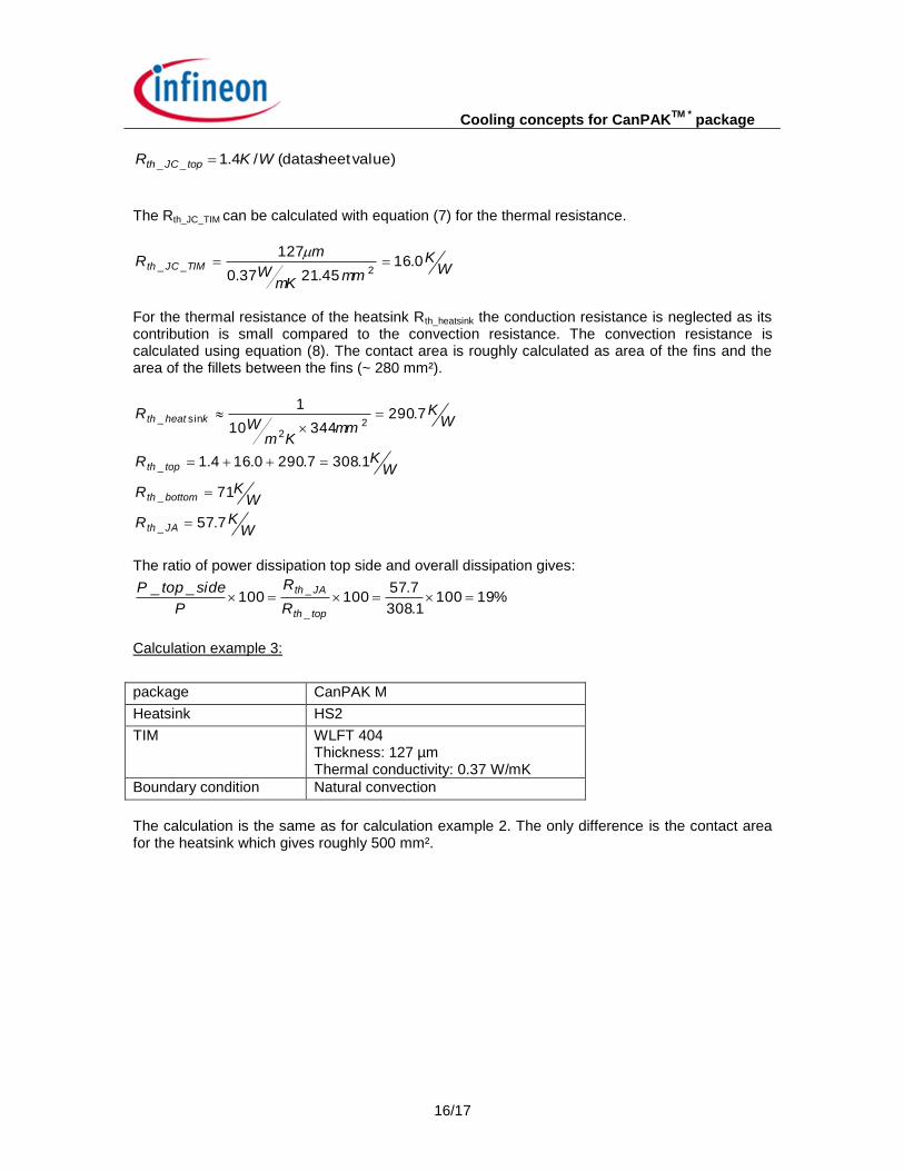
Calculation example 2:
package CanPAK M
Heatsink HS1
TIM WLFT 404 Thickness: 127 µm Thermal conductivity: 0.37 W/mK
Boundary condition Natural convection
Cooling concepts for CanPAKTM *
package
16/17
value) (datasheet /4.1__ WKR topJCth
The Rth_JC_TIM can be calculated with equation (7) for the thermal resistance.
WK
mmmK
W
mR TIMJCth 0.16
45.2137.0
127
2__
For the thermal resistance of the heatsink Rth_heatsink the conduction resistance is neglected as its contribution is small compared to the convection resistance. The convection resistance is calculated using equation (8). The contact area is roughly calculated as area of the fins and the area of the fillets between the fins (~ 280 mm²).
WKR
WKR
WKR
WK
mmKm
WR
JAth
bottomth
topth
kheatth
7.57
71
1.3087.2900.164.1
7.29034410
1
_
_
_
22
sin_
The ratio of power dissipation top side and overall dissipation gives:
%191001.308
7.57100100
__
_
_
topth
JAth
R
R
P
sidetopP
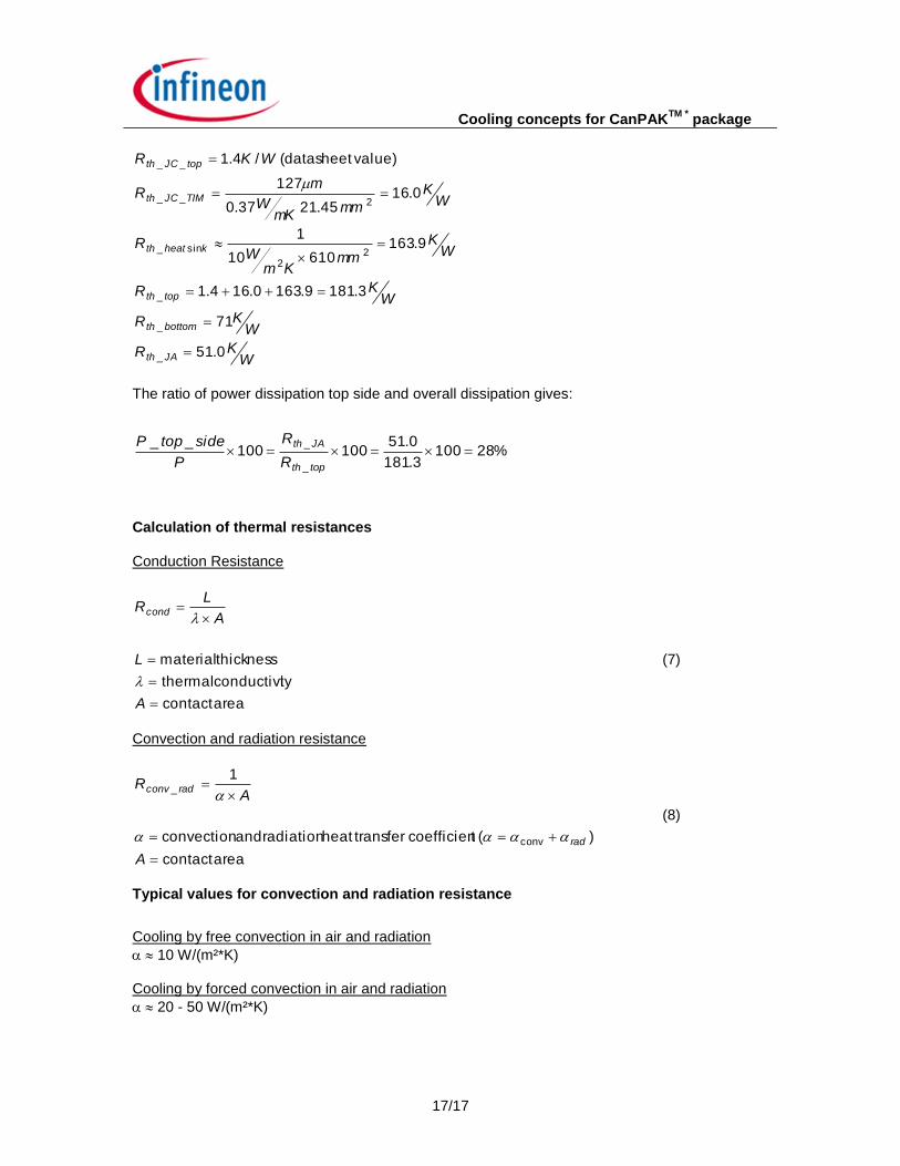
Calculation example 3:
package CanPAK M
Heatsink HS2
TIM WLFT 404 Thickness: 127 µm Thermal conductivity: 0.37 W/mK
Boundary condition Natural convection
The calculation is the same as for calculation example 2. The only difference is the contact area for the heatsink which gives roughly 500 mm².
Cooling concepts for CanPAKTM *
package
17/17
WKR
WKR
WKR
WK
mmKm
WR
WK
mmmK
W
mR
WKR
JAth
bottomth
topth
kheatth
TIMJCth
topJCth
0.51
71
3.1819.1630.164.1
9.163 61010
1
0.16 45.2137.0
127
value) (datasheet /4.1
_
_
_
22
sin_
2__
__
The ratio of power dissipation top side and overall dissipation gives:
%281003.181
0.51100100
__
_
_
topth
JAth
R
R
P
sidetopP
Calculation of thermal resistances Conduction Resistance
area contact
tyconductivi thermal
thickness material
A
L
A
LRcond
(7)
Convection and radiation resistance
area contact
)( tcoefficien transfer heat radiation and convection
1
conv
_
A
AR
rad
radconv
(8)
Typical values for convection and radiation resistance
Cooling by free convection in air and radiation
10 W/(m²*K) Cooling by forced convection in air and radiation
20 - 50 W/(m²*K)