Embed Size (px)
Citation preview
82559 EEPROM Map and Programming InformationApplication Note (AP-394)
Revision 3.0
June 2003
ii Application Note (AP-394)
Information in this document is provided in connection with Intel products. No license, express or implied, by estoppel or otherwise, to any intellectual property rights is granted by this document. Except as provided in Intel's Terms and Conditions of Sale for such products, Intel assumes no liability whatsoever, and Intel disclaims any express or implied warranty, relating to sale and/or use of Intel products including liability or warranties relating to fitness for a particular purpose, merchantability, or infringement of any patent, copyright or other intellectual property right. Intel products are not intended for use in medical, life saving, or life sustaining applications.
Intel may make changes to specifications and product descriptions at any time, without notice.
Designers must not rely on the absence or characteristics of any features or instructions marked "reserved" or "undefined." Intel reserves these for future definition and shall have no responsibility whatsoever for conflicts or incompatibilities arising from future changes to them.
The 82557, 82558, or 82559 may contain design defects or errors known as errata which may cause the product to deviate from published specifications. Current characterized errata are available on request.
Contact your local Intel sales office or your distributor to obtain the latest specifications and before placing your product order.
Contact your local Intel sales office or your distributor to obtain the latest specifications and before placing your product order.
Copies of documents which have an ordering number and are referenced in this document or other Intel literature may be obtained by calling 1-800-548-4725 or by visiting Intel's website at http://www.intel.com.
Copyright © 2003, Intel Corporation.
* Third-party brands and names are the property of their respective owners.
Revision History
Revision Date Revision Description
June 2003 3.0 First public release.
Contents
1.0 INTRODUCTION AND SCOPE ............................................................................................................11.1 EEPROM Device and Interface.......................................................................................11.2 EEPROM Programming Procedure Overview.................................................................11.3 EEUPDATE Utility ...........................................................................................................2
1.3.1 Command Line Parameters ...............................................................................2
2.0 82559 EEPROM FORMAT AND CONTENTS ....................................................................................1
2.1 82559 Allocation of EEPROM Space ..............................................................................22.2 Ethernet Individual Address (Words 00-02h) ..................................................................22.3 82559 Compatibility Fields (Word 03h) ...........................................................................2
2.3.1 Compatibility Byte 0 (Word 03h, Low Byte) ........................................................22.3.2 Compatibility Byte 1 (Word 03h, High Byte) .......................................................3
2.4 82559 Hardware Description Fields (Words 05h - 0Ah)..................................................42.4.1 Controller Type (Word 05h, High Byte) ..............................................................42.4.2 Connectors (Word 05h, Low Byte) .....................................................................42.4.3 PHY Device Records (Words 06-07h)................................................................42.4.4 PWA Number (Words 08-09h)............................................................................5
2.5 82559 Product Identification............................................................................................52.5.1 EEPROM ID (Word 0Ah)....................................................................................52.5.2 82559 Product Identification (Words 0B-0Ch)....................................................72.5.3 Subsystem ID (Word 0Bh)..................................................................................82.5.4 Subsystem Vendor ID (Word 0Ch).....................................................................8
2.6 82559 Other Information .................................................................................................92.6.1 SMBus Address, CIS Pointer, and HB Packet Pointer
(Word 0Dh)92.6.2 Boot Configuration (Word 30h)...........................................................................92.6.3 PXE Configuration (Word 3Bh) ........................................................................102.6.4 Modem Configuration (Words FBh - FEh) ........................................................112.6.5 Heartbeat Packet Structure within the EEPROM .............................................112.6.6 Checksum (Word 3FF or FFh)..........................................................................12
Application Note (AP-394) iii

iv Application Note (AP-394)
82559 EEPROM Map and Programming Information
1.0 Introduction and Scope
This document describes the EEPROM map and contents for products based upon the Intel 82559ER Fast Ethernet* controllers.
Part of the EEPROM is used for hardware configuration, while part of the EEPROM space is read by Intel-supplied drivers and other configuration software to determine and configure features specific to that design. For compatibility, Intel does not create separate drivers for the 82559 controllers.
1.1 EEPROM Device and Interface
The serial EEPROM stores configuration data for the controller. The EEPROM is a serial in/serial out device. The 82559 supports 64-word or 256-word sized EEPROMs,
In PCI designs that do not use TCO functionality, the controller only requires an EEPROM that contains 64 registers of 16 bits per register. The 256-register, (16 bits per register) EEPROM device is required in TCO enabled systems to store the heartbeat packet. CardBus systems require the larger EEPROM size to store the Card Information Structure (CIS). The 82559 auto-detects the EEPROM size via a dummy zero mechanism following reset.
All accesses, read and write, are preceded by a command instruction to the EEPROM. The command instructions begin with a logical one as a start bit, two opcode bits (read, write, erase, etc.), and six bits of address. The address field is six bits for a 64 register EEPROM. The end of the address field is indicated by a dummy zero bit from the EEPROM. This indicates that the entire address field has been transferred to the EEPROM. A command is issued by asserting the EEPROM Chip Select (EECS) signal from the controller and clocking the data out of the EEPROM Data Input (EEDI) pin into the EEPROM on its data input pin relative to the EEPROM Shift Clock (EESK) controller output. The EECS signal is de-asserted after completion of the EEPROM cycle (command, address and data).
In designs employing 64-register EEPROM, the EEPROM read is approximately 6,000 clock cycles long (180 microseconds at 33 MHz) or 12,000 clock cycles in WOL mode (360 microseconds at 33 MHz). Conversely, in designs employing 256-register EEPROM, the EEPROM read is approximately 24,000 clock cycles long (720 microseconds at 33 MHz) or 48,000 clock cycles in WOL mode (1,440 microseconds at 33 MHz). The system is required to provide a valid clock on the CLK pin for this time period after the de-assertion of RST#, even if the ISOLATE# pin is asserted (the CLK input is not isolated until the EEPROM accesses are complete).
The 82559 performs an automatic read of three registers from the EEPROM after the de-assertion of reset. The 82559 provides a sequence of 110A5A4A3A2A1A0b (start bit, read opcode, address) and read the 16 bits of data that follow the dummy zero, assuming the most significant bit first. The process is then repeated the for the next two addresses.
1.2 EEPROM Programming Procedure Overview
The EEPROM for PRO/100+ adapter products is programmed in-line at a Final Acceptance Test (FAT) station. This allows the use of a surface mount technology (SMT) EEPROM, which is otherwise difficult to handle with off-line automated programming equipment. The Bill of
Application Note (AP-394) 1
82559 EEPROM Map and Programming Information
Materials (BOM) for an 82559-based solution requires a blank EEPROM (type 93C66 for TCO-enabled systems, type 93C46 otherwise). For the 82559, the image programmed into the EEPROM is specified by two controlled documents:
1. The 8255X EEPROM Map and Programming Information (AP-394) application note (this document).
2. A program file that is unique for each printed board assembly (PBA) and contains the default EEPROM values for that particular PBA. This file can be created in a simple text editor and follows the format shown in Appendix A. Appendix A provides an example of an EEPROM map for a 82559-based design.
EEPROMs may be pre-programmed prior to soldering it onto a board. Some LAN On Motherboard (LOM) designers may prefer this method over in-line programming.
The EEPROM image consists of two types of data: static data, which is fully described by this document, and dynamic (or serialized) data, which varies for each unit programmed. The dynamic data consists of the product’s Ethernet Individual Address (IA) and the EEPROM checksum. In TCO systems, the heartbeat packet, SMBus address and heartbeat packet pointer are also dynamic data.
1.3 EEUPDATE Utility
Intel has created a DOS utility that meets the two basic requirements for an in-circuit programming utility. First, the utility can be used to update EEPROM images as part of an end-of-line production tool. Secondly, it can be used as a standalone development tool. The tool uses the two basic data files outlined in the following section (static data file, and IA address file).
The EEUPDATE utility is flexible and can be used to update the entire EEPROM image or to update only the IA address of the card. This utility is only available to OEM customers.
1.3.1 Command Line Parameters
The DOS command format is as follows:
EEUPDATE Parameter_ 1 Parameter_2where:
Parameter _1 = filename or /D
Parameter_2 = filename or /A
Parameter 1:
Parameter 1 in this example case is file1.eep, which contains the complete EEPROM image in a specific format and is used to update the complete EEPROM. All comments in the “.eep” file must be preceded by a semicolon (;). The file names given here are only examples.
Parameter 1 can also be a switch: /D. The switch /D implies, do not update the complete EEPROM image.
Parameter 2:
2 Application Note (AP-394)

82559 EEPROM Map and Programming Information
Parameter 2 in this example case is file2.dat, which contains a list of IA addresses. The EEUPDATE utility picks up the first unused address from this file and uses it to update the EEPROM. An address is marked as used by following the address with a date stamp. When the utility uses a specific address, it updates that address as used in a log file called eelog.dat. This file should then be used as the dat file for the next update. The Parameter 2 can also be /A, which implies, do not update the IA address.
See Appendix A for an example of the raw EEPROM contents.
Application Note (AP-394) 3

82559 EEPROM Map and Programming Information
4 Application Note (AP-394)
82559 EEPROM Map and Programming Information
2.0 82559 EEPROM Format and Contents
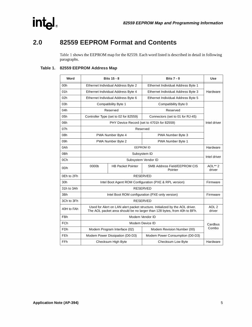
Table 1 shows the EEPROM map for the 82559. Each word listed is described in detail in following paragraphs.
Table 1. 82559 EEPROM Address Map
Word Bits 15 - 8 Bits 7 - 0 Use
00h Ethernet Individual Address Byte 2 Ethernet Individual Address Byte 1
Hardware01h Ethernet Individual Address Byte 4 Ethernet Individual Address Byte 3
02h Ethernet Individual Address Byte 6 Ethernet Individual Address Byte 5
03h Compatibility Byte 1 Compatibility Byte 0
Intel driver
04h Reserved Reserved
05h Controller Type (set to 02 for 82559) Connectors (set to 01 for RJ-45)
06h PHY Device Record (set to 4701h for 82559)
07h Reserved
08h PWA Number Byte 4 PWA Number Byte 3
09h PWA Number Byte 2 PWA Number Byte 1
0Ah EEPROM ID Hardware
0Bh Subsystem IDIntel driver
0Ch Subsystem Vendor ID
0Dh 0000b HB Packet Pointer SMB Address Field/EEPROM CIS Pointer
AOL** 2 driver
0Eh to 2Fh RESERVED
30h Intel Boot Agent ROM Configuration (PXE & RPL version) Firmware
31h to 3Ah RESERVED
3Bh Intel Boot ROM configuration (PXE-only version) Firmware
3Ch to 3Fh RESERVED
40H to FAh Used for Alert on LAN alert packet structure. Initialized by the AOL driver.The AOL packet area should be no larger than 128 bytes, from 40h to BFh.
AOL 2 driver
FBh Modem Vendor ID
Cardbus Combo
FCh Modem Device ID
FDh Modem Program Interface (02) Modem Revision Number (00)
FEh Modem Power Dissipation (D0-D3) Modem Power Consumption (D0-D3)
FFh Checksum High Byte Checksum Low Byte Hardware
Application Note (AP-394) 5
82559 EEPROM Map and Programming Information
2.1 82559 Allocation of EEPROM Space
Words 00h through 02h are used by the hardware and are common to all controllers.
Note: Words 03h through 09h are used by the Intel PRO/100+ driver, version 3.0 and later. The Intel driver uses this space as indicated here and defined later in this section. Non-Intel drivers can use this space as required.
2.2 Ethernet Individual Address (Words 00-02h)
Ethernet Individual Address (IA) is a six-byte field that must be unique for each adapter card or board and unique for each copy of the EEPROM image. The first three bytes are vendor specific. The last three bytes must be unique for each copy of the EEPROM. It is anticipated that OEM versions of the product may be required to have non-Intel ID’s in the first three byte positions. The Intel default is shown in the following table. Notice that the Ethernet Individual address is byte-swapped, as indicated next.
Note: The Individual Address (IA) bytes read from the EEPROM is used by the 82559 until an IA Setup command is issued by software. The IA defined by the IA Setup command overrides the IA read from the EEPROM.
2.3 82559 Compatibility Fields (Word 03h)
This field is used by the Intel driver. One word in the EEPROM image is reserved for compatibility information. New bits within these fields will be defined as the need arises for determining software compatibility between various hardware revisions. The bits discussed next are initialized during manufacturing and should be considered read only by software.
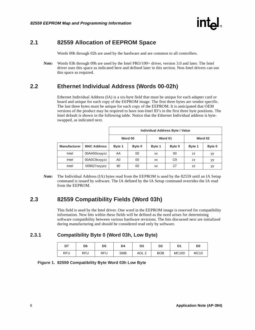
2.3.1 Compatibility Byte 0 (Word 03h, Low Byte)
Figure 1. 82559 Compatibility Byte Word 03h Low Byte
Individual Address Byte / Value
Word 00 Word 01 Word 02
Manufacturer MAC Address Byte 1 Byte 0 Byte 1 Byte 0 Byte 1 Byte 0
Intel 00AA00xxyyzz AA 00 xx 00 zz yy
Intel 00A0C9xxyyzz A0 00 xx C9 zz yy
Intel 009027xxyyzz 90 00 xx 27 zz yy
D7 D6 D5 D4 D3 D2 D1 D0
RFU RFU RFU SMB AOL 2 BOB MC100 MC10
6 Application Note (AP-394)
82559 EEPROM Map and Programming Information
Fields in this byte are described next.
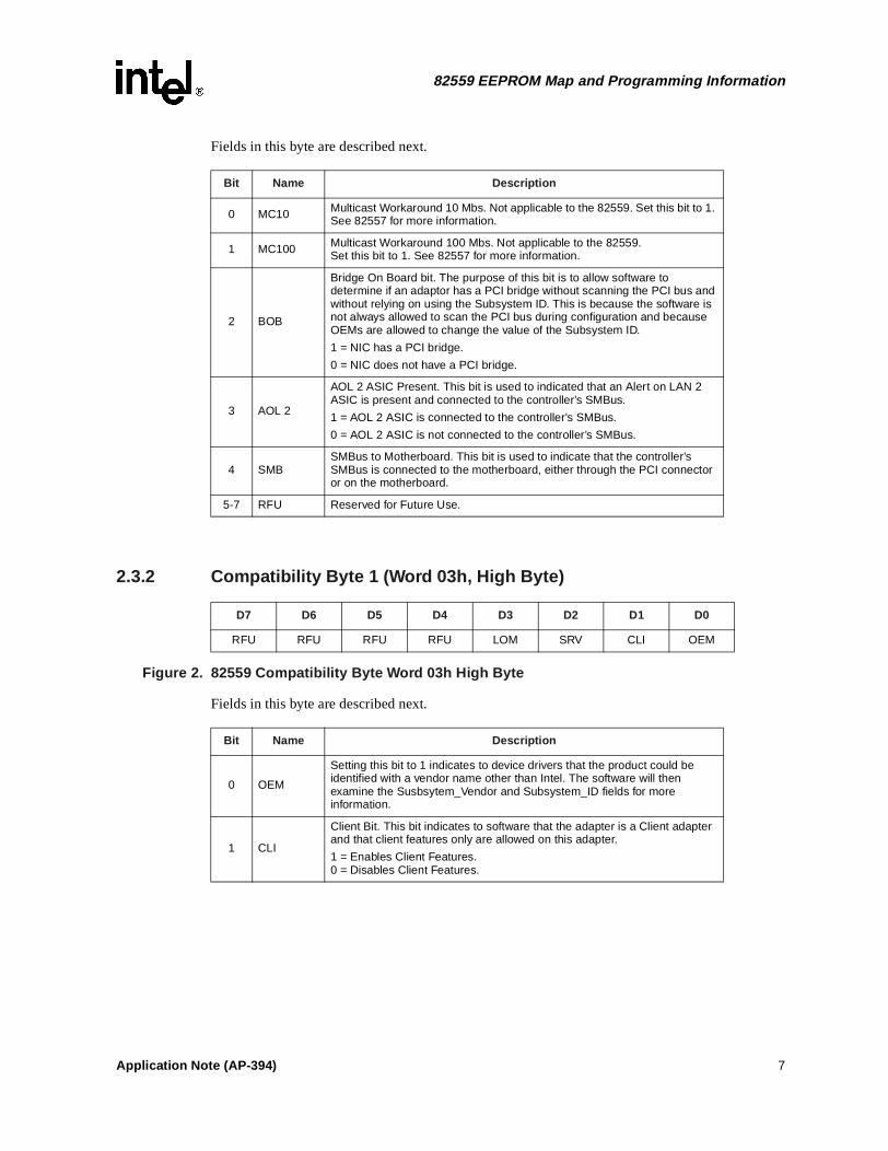
2.3.2 Compatibility Byte 1 (Word 03h, High Byte)
Figure 2. 82559 Compatibility Byte Word 03h High Byte
Fields in this byte are described next.
Bit Name Description
0 MC10 Multicast Workaround 10 Mbs. Not applicable to the 82559. Set this bit to 1. See 82557 for more information.
1 MC100 Multicast Workaround 100 Mbs. Not applicable to the 82559. Set this bit to 1. See 82557 for more information.
2 BOB
Bridge On Board bit. The purpose of this bit is to allow software to determine if an adaptor has a PCI bridge without scanning the PCI bus and without relying on using the Subsystem ID. This is because the software is not always allowed to scan the PCI bus during configuration and because OEMs are allowed to change the value of the Subsystem ID.
1 = NIC has a PCI bridge.
0 = NIC does not have a PCI bridge.
3 AOL 2
AOL 2 ASIC Present. This bit is used to indicated that an Alert on LAN 2 ASIC is present and connected to the controller’s SMBus.
1 = AOL 2 ASIC is connected to the controller’s SMBus.
0 = AOL 2 ASIC is not connected to the controller’s SMBus.
4 SMBSMBus to Motherboard. This bit is used to indicate that the controller’s SMBus is connected to the motherboard, either through the PCI connector or on the motherboard.
5-7 RFU Reserved for Future Use.
D7 D6 D5 D4 D3 D2 D1 D0
RFU RFU RFU RFU LOM SRV CLI OEM
Bit Name Description
0 OEM
Setting this bit to 1 indicates to device drivers that the product could be identified with a vendor name other than Intel. The software will then examine the Susbsytem_Vendor and Subsystem_ID fields for more information.
1 CLI
Client Bit. This bit indicates to software that the adapter is a Client adapter and that client features only are allowed on this adapter.
1 = Enables Client Features. 0 = Disables Client Features.
Application Note (AP-394) 7
82559 EEPROM Map and Programming Information
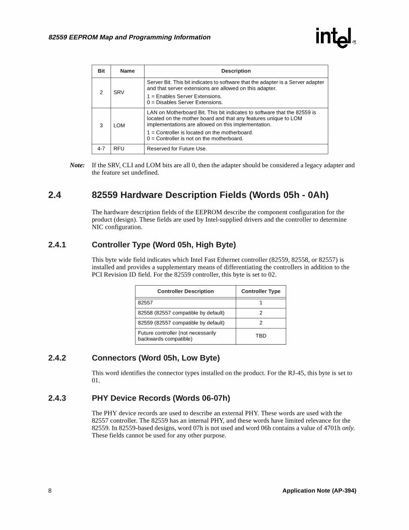
Note: If the SRV, CLI and LOM bits are all 0, then the adapter should be considered a legacy adapter and the feature set undefined.
2.4 82559 Hardware Description Fields (Words 05h - 0Ah)
The hardware description fields of the EEPROM describe the component configuration for the product (design). These fields are used by Intel-supplied drivers and the controller to determine NIC configuration.
2.4.1 Controller Type (Word 05h, High Byte)
This byte wide field indicates which Intel Fast Ethernet controller (82559, 82558, or 82557) is installed and provides a supplementary means of differentiating the controllers in addition to the PCI Revision ID field. For the 82559 controller, this byte is set to 02.
2.4.2 Connectors (Word 05h, Low Byte)
This word identifies the connector types installed on the product. For the RJ-45, this byte is set to 01.
2.4.3 PHY Device Records (Words 06-07h)
The PHY device records are used to describe an external PHY. These words are used with the 82557 controller. The 82559 has an internal PHY, and these words have limited relevance for the 82559. In 82559-based designs, word 07h is not used and word 06h contains a value of 4701h only. These fields cannot be used for any other purpose.
2 SRV
Server Bit. This bit indicates to software that the adapter is a Server adapter and that server extensions are allowed on this adapter.
1 = Enables Server Extensions. 0 = Disables Server Extensions.
3 LOM
LAN on Motherboard Bit. This bit indicates to software that the 82559 is located on the mother board and that any features unique to LOM implementations are allowed on this implementation.
1 = Controller is located on the motherboard. 0 = Controller is not on the motherboard.
4-7 RFU Reserved for Future Use.
Bit Name Description
Controller Description Controller Type
82557 1
82558 (82557 compatible by default) 2
82559 (82557 compatible by default) 2
Future controller (not necessarily backwards compatible) TBD
8 Application Note (AP-394)
82559 EEPROM Map and Programming Information
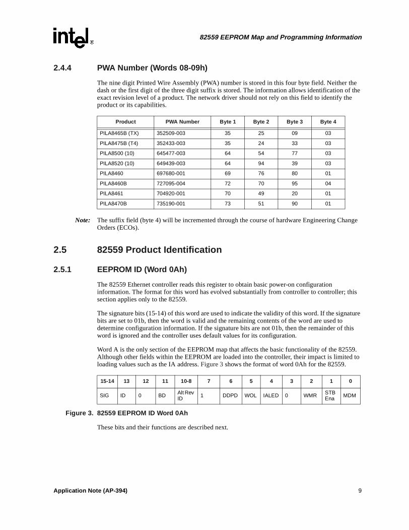
2.4.4 PWA Number (Words 08-09h)
The nine digit Printed Wire Assembly (PWA) number is stored in this four byte field. Neither the dash or the first digit of the three digit suffix is stored. The information allows identification of the exact revision level of a product. The network driver should not rely on this field to identify the product or its capabilities.
Note: The suffix field (byte 4) will be incremented through the course of hardware Engineering Change Orders (ECOs).
2.5 82559 Product Identification
2.5.1 EEPROM ID (Word 0Ah)
The 82559 Ethernet controller reads this register to obtain basic power-on configuration information. The format for this word has evolved substantially from controller to controller; this section applies only to the 82559.
The signature bits (15-14) of this word are used to indicate the validity of this word. If the signature bits are set to 01b, then the word is valid and the remaining contents of the word are used to determine configuration information. If the signature bits are not 01b, then the remainder of this word is ignored and the controller uses default values for its configuration.
Word A is the only section of the EEPROM map that affects the basic functionality of the 82559. Although other fields within the EEPROM are loaded into the controller, their impact is limited to loading values such as the IA address. Figure 3 shows the format of word 0Ah for the 82559.
Figure 3. 82559 EEPROM ID Word 0Ah
These bits and their functions are described next.
Product PWA Number Byte 1 Byte 2 Byte 3 Byte 4
PILA8465B (TX) 352509-003 35 25 09 03
PILA8475B (T4) 352433-003 35 24 33 03
PILA8500 (10) 645477-003 64 54 77 03
PILA8520 (10) 649439-003 64 94 39 03
PILA8460 697680-001 69 76 80 01
PILA8460B 727095-004 72 70 95 04
PILA8461 704920-001 70 49 20 01
PILA8470B 735190-001 73 51 90 01
15-14 13 12 11 10-8 7 6 5 4 3 2 1 0
SIG ID 0 BD Alt Rev ID 1 DDPD WOL IALED 0 WMR STB
Ena MDM
Application Note (AP-394) 9
82559 EEPROM Map and Programming Information
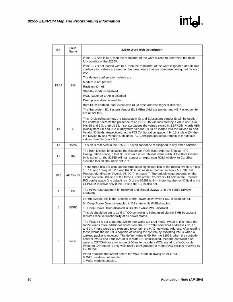
Bit Field Name 82559 Word 0Ah Description
15:14 SIG
If the SIG field is 01b, then the remainder of the word is read to determine the basic functionality of the 82559.
If the SIG is not loaded with 01b, then the remainder of the word is ignored and default configuration values are used for the parameters that are otherwise configured by word. 0Ah
The default configuration values are:
Modem is not present
Revision ID - 08
Standby mode is disabled
WOL (wake on LAN) is disabled
Deep power down is enabled
Boot ROM enabled, boot expansion ROM base address register disabled. The Subsystem ID, System Vendor ID, SMBus Address pointer and HB Packet pointer are all set to 0.
13 ID
This ID bit indicates how the Subsystem ID and Subsystem Vendor ID will be used. If the controller detects the presence of an EEPROM (as indicated by a value of 01b in bits 15 and 14), then bit 13, if set (1) causes the values stored in EEPROM, words 0Bh (Subsystem ID) and 0Ch (Subsystem Vendor ID), to be loaded into the Device ID and Vendor ID fields, respectively, in the PCI Configuration space. If bit 13 is clear (0), then the Device ID and Vendor ID fields in PCI Configuration space remain at the default values. See Section 2.5.2.
12 RSVD This bit is reserved in the 82559. This bit cannot be reassigned to any other function.
11 BD
The Boot Disable bit disables the Expansion ROM Base Address Register (PCI Configuration space, offset 30H) when it is set. Default value is 0b. If the Boot Disable bit is set to ‘1’, the 82559 will not request an expansion ROM window. In CardBus systems this bit should be set to ‘1’.
10:8 Alt Rev ID
These three bits are used as the three least significant bits of the device revision, if bits 15, 14, and 13 equal 011b and the ID is set as described in Section 2.5.2, “82559 Product Identification (Words 0B-0Ch)” on page 7. The default value depends on the silicon revision. These are the three LS bits of the 82559’s rev ID field in the Ethernet PCI config space (the default rev ID of the 82559 is 8 h). Note that the rev ID field in the EEPROM is active only if the ID field (bit 13) is also set.
7 PM The Power Management bit reserved and should always ‘1’ in the 82559 (always enabled).
6 DDPD
For the 82559, this is the “Disable Deep Power Down while PME is disabled” bit.
0 - Deep Power Down is enabled in D3 state while PME-disabled.
1 - Deep Power Down disabled in D3 state while PME-disabled.
This bit should be set to 1b if a TCO controller is being used via the SMB because it requires receive functionality at all power states.
5 WOL
The WOL bit is set to put the 82559 into Wake On LAN mode. When in this mode the 82559 reads three additional words from the EEPROM from word addresses 0h, 1h, and 2h. These words are expected to contain the MAC Individual Address. After reading these words the 82559 is capable of waking the system by asserting PME# when a wakeup packet is received. The default value is 0b. For the 82559, when the controller asserts PME# and if the 82559 is in state D3, uninitialized, then the controller also asserts CSTCHG for a minimum of 50ms to provide a WOL signal to a WOL cable. Wake on LAN mode is only valid until a configuration or memory/IO cycle is received by the 82559.
When enabled, the 82559 enters the WOL mode following an ALTRST:0’ WOL mode is not enabled1’ WOL mode is enabled.
10 Application Note (AP-394)
82559 EEPROM Map and Programming Information
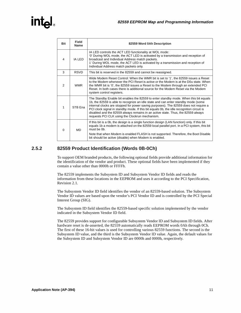
2.5.2 82559 Product Identification (Words 0B-0Ch)
To support OEM branded products, the following optional fields provide additional information for the identification of the vendor and product. These optional fields have been implemented if they contain a value other than 0000h or FFFFh.
The 82559 implements the Subsystem ID and Subsystem Vendor ID fields and reads the information from these locations in the EEPROM and uses it according to the PCI Specification, Revision 2.1.
The Subsystem Vendor ID field identifies the vendor of an 82559-based solution. The Subsystem Vendor ID values are based upon the vendor’s PCI Vendor ID and is controlled by the PCI Special Interest Group (SIG).
The Subsystem ID field identifies the 82559-based specific solution implemented by the vendor indicated in the Subsystem Vendor ID field.
The 82559 provides support for configurable Subsystem Vendor ID and Subsystem ID fields. After hardware reset is de-asserted, the 82559 automatically reads EEPROM words 0Ah through 0Ch. The first of these 16-bit values is used for controlling various 82559 functions. The second is the Subsystem ID value, and the third is the Subsystem Vendor ID value. Again, the default values for the Subsystem ID and Subsystem Vendor ID are 0000h and 0000h, respectively.
4 IA LED
IA LED controls the ACT LED functionality at WOL mode: ‘0’ During WOL mode, the ACT LED is activated by a transmission and reception of broadcast and Individual Address match packets.1’ During WOL mode, the ACT LED is activated by a transmission and reception of Individual Address match packets only.
3 RSVD This bit is reserved in the 82559 and cannot be reassigned.
2 WMR
Wide Modem Reset Control: When the WMR bit is set to ‘1’, the 82559 issues a Reset to the Modem whenever the PCI Reset is active or the Modem is at the D0u state. When the WMR bit is ‘0’, the 82559 issues a Reset to the Modem through an extended PCI Reset. In both cases there is additional source for the Modem Reset via the Modem system control registers.
1 STB Ena
The Standby Enable bit enables the 82559 to enter standby mode. When this bit equals 1b, the 82559 is able to recognize an idle state and can enter standby mode (some internal clocks are stopped for power saving purposes). The 82559 does not require a PCI clock signal in standby mode. If this bit equals 0b, the idle recognition circuit is disabled and the 82559 always remains in an active state. Thus, the 82559 always requests PCI CLK using the Clockrun mechanism.
0 MD
If this bit is a 0b, the design is a single function design (LAN function) only. If this bit equals 1b a modem is attached on the 82559 local parallel port. In a PCI system, this bit must be 0b.
Note that when Modem is enabled FLASH is not supported. Therefore, the Boot Disable bit should be active (disable) when Modem is enabled.
Bit Field Name 82559 Word 0Ah Description
Application Note (AP-394) 11
82559 EEPROM Map and Programming Information
em ID
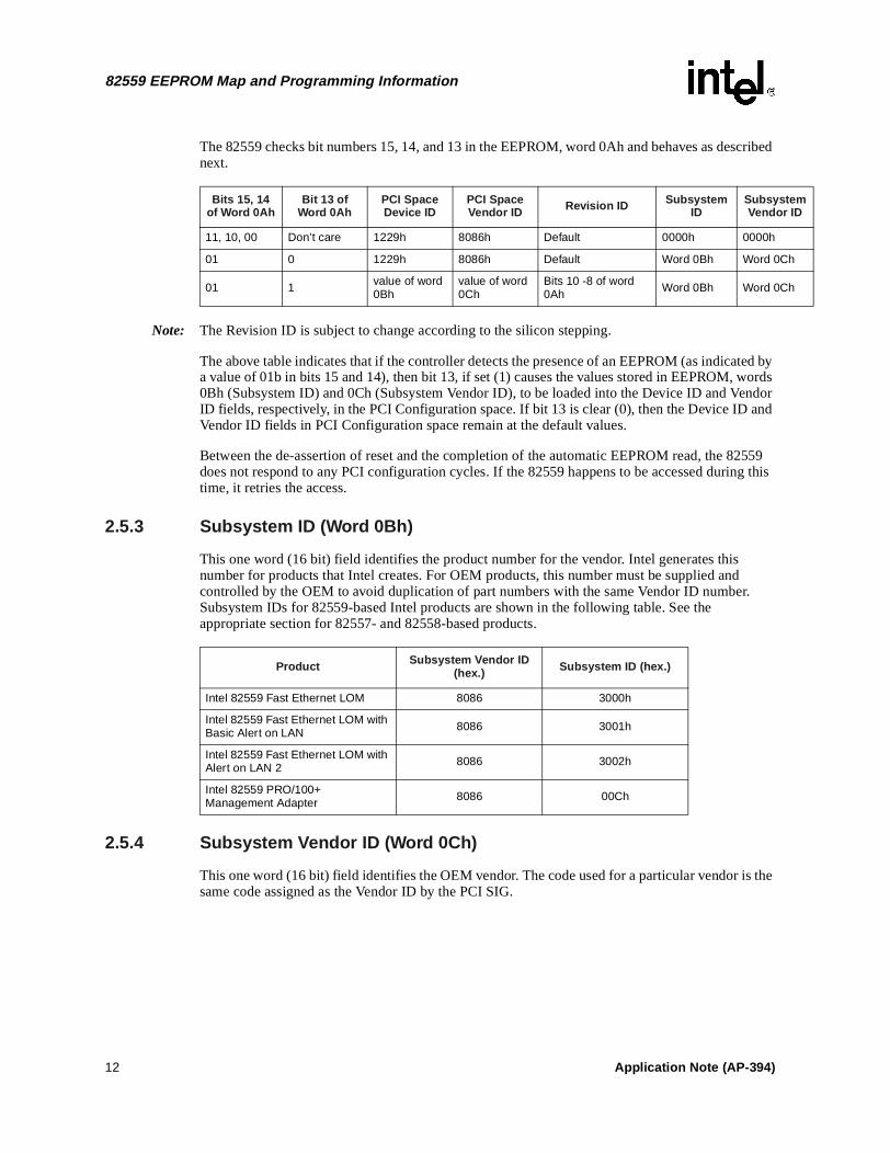
The 82559 checks bit numbers 15, 14, and 13 in the EEPROM, word 0Ah and behaves as described next.
Note: The Revision ID is subject to change according to the silicon stepping.
The above table indicates that if the controller detects the presence of an EEPROM (as indicated by a value of 01b in bits 15 and 14), then bit 13, if set (1) causes the values stored in EEPROM, words 0Bh (Subsystem ID) and 0Ch (Subsystem Vendor ID), to be loaded into the Device ID and Vendor ID fields, respectively, in the PCI Configuration space. If bit 13 is clear (0), then the Device ID and Vendor ID fields in PCI Configuration space remain at the default values.
Between the de-assertion of reset and the completion of the automatic EEPROM read, the 82559 does not respond to any PCI configuration cycles. If the 82559 happens to be accessed during this time, it retries the access.
2.5.3 Subsystem ID (Word 0Bh)
This one word (16 bit) field identifies the product number for the vendor. Intel generates this number for products that Intel creates. For OEM products, this number must be supplied and controlled by the OEM to avoid duplication of part numbers with the same Vendor ID number. Subsystem IDs for 82559-based Intel products are shown in the following table. See the appropriate section for 82557- and 82558-based products.
2.5.4 Subsystem Vendor ID (Word 0Ch)
This one word (16 bit) field identifies the OEM vendor. The code used for a particular vendor is the same code assigned as the Vendor ID by the PCI SIG.
Bits 15, 14 of Word 0Ah
Bit 13 of Word 0Ah
PCI SpaceDevice ID
PCI SpaceVendor ID Revision ID Subsystem
IDSubsystVendor
11, 10, 00 Don’t care 1229h 8086h Default 0000h 0000h
01 0 1229h 8086h Default Word 0Bh Word 0Ch
01 1 value of word 0Bh
value of word 0Ch
Bits 10 -8 of word 0Ah Word 0Bh Word 0Ch
Product Subsystem Vendor ID (hex.) Subsystem ID (hex.)
Intel 82559 Fast Ethernet LOM 8086 3000h
Intel 82559 Fast Ethernet LOM with Basic Alert on LAN 8086 3001h
Intel 82559 Fast Ethernet LOM with Alert on LAN 2 8086 3002h
Intel 82559 PRO/100+Management Adapter 8086 00Ch
12 Application Note (AP-394)
82559 EEPROM Map and Programming Information
2.6 82559 Other Information
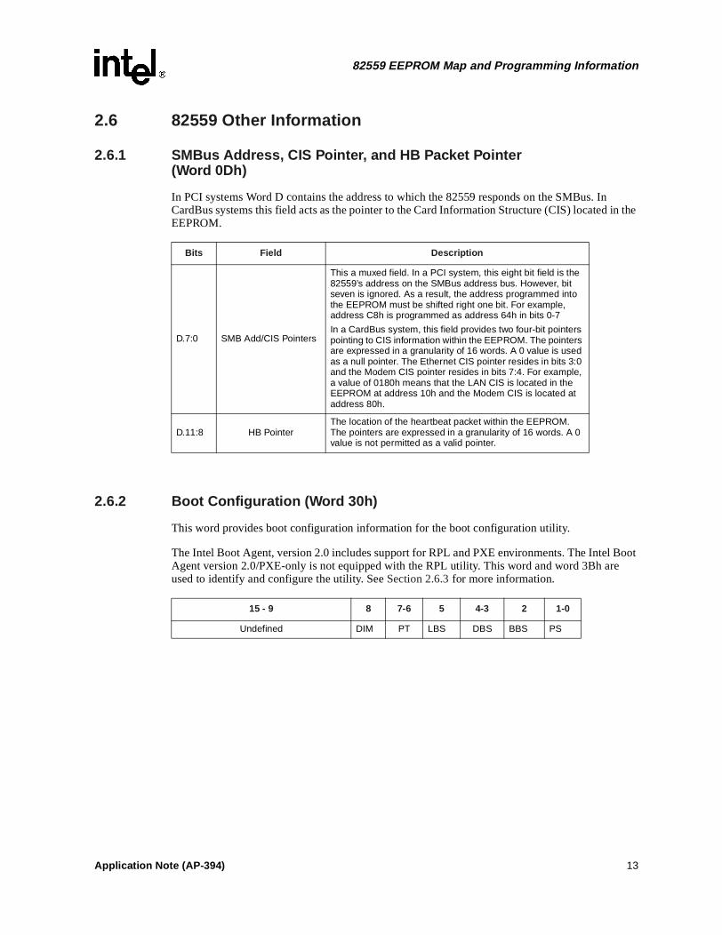
2.6.1 SMBus Address, CIS Pointer, and HB Packet Pointer(Word 0Dh)
In PCI systems Word D contains the address to which the 82559 responds on the SMBus. In CardBus systems this field acts as the pointer to the Card Information Structure (CIS) located in the EEPROM.
2.6.2 Boot Configuration (Word 30h)
This word provides boot configuration information for the boot configuration utility.
The Intel Boot Agent, version 2.0 includes support for RPL and PXE environments. The Intel Boot Agent version 2.0/PXE-only is not equipped with the RPL utility. This word and word 3Bh are used to identify and configure the utility. See Section 2.6.3 for more information.
Bits Field Description
D.7:0 SMB Add/CIS Pointers
This a muxed field. In a PCI system, this eight bit field is the 82559’s address on the SMBus address bus. However, bit seven is ignored. As a result, the address programmed into the EEPROM must be shifted right one bit. For example, address C8h is programmed as address 64h in bits 0-7
In a CardBus system, this field provides two four-bit pointers pointing to CIS information within the EEPROM. The pointers are expressed in a granularity of 16 words. A 0 value is used as a null pointer. The Ethernet CIS pointer resides in bits 3:0 and the Modem CIS pointer resides in bits 7:4. For example, a value of 0180h means that the LAN CIS is located in the EEPROM at address 10h and the Modem CIS is located at address 80h.
D.11:8 HB PointerThe location of the heartbeat packet within the EEPROM. The pointers are expressed in a granularity of 16 words. A 0 value is not permitted as a valid pointer.
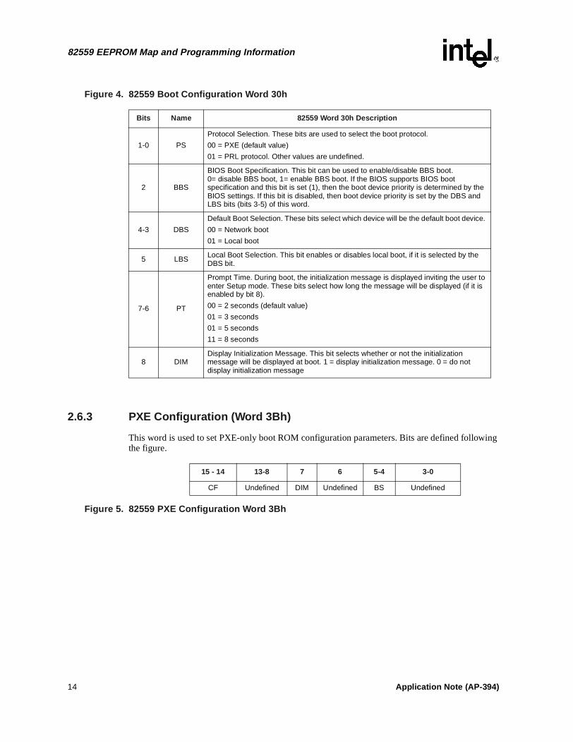
15 - 9 8 7-6 5 4-3 2 1-0
Undefined DIM PT LBS DBS BBS PS
Application Note (AP-394) 13
82559 EEPROM Map and Programming Information
Figure 4. 82559 Boot Configuration Word 30h
2.6.3 PXE Configuration (Word 3Bh)
This word is used to set PXE-only boot ROM configuration parameters. Bits are defined following the figure.
Figure 5. 82559 PXE Configuration Word 3Bh
Bits Name 82559 Word 30h Description
1-0 PS
Protocol Selection. These bits are used to select the boot protocol.
00 = PXE (default value)
01 = PRL protocol. Other values are undefined.
2 BBS
BIOS Boot Specification. This bit can be used to enable/disable BBS boot. 0= disable BBS boot, 1= enable BBS boot. If the BIOS supports BIOS boot specification and this bit is set (1), then the boot device priority is determined by the BIOS settings. If this bit is disabled, then boot device priority is set by the DBS and LBS bits (bits 3-5) of this word.
4-3 DBS
Default Boot Selection. These bits select which device will be the default boot device.
00 = Network boot
01 = Local boot
5 LBS Local Boot Selection. This bit enables or disables local boot, if it is selected by the DBS bit.
7-6 PT
Prompt Time. During boot, the initialization message is displayed inviting the user to enter Setup mode. These bits select how long the message will be displayed (if it is enabled by bit 8).
00 = 2 seconds (default value)
01 = 3 seconds
01 = 5 seconds
11 = 8 seconds
8 DIMDisplay Initialization Message. This bit selects whether or not the initialization message will be displayed at boot. 1 = display initialization message. 0 = do not display initialization message
15 - 14 13-8 7 6 5-4 3-0
CF Undefined DIM Undefined BS Undefined
14 Application Note (AP-394)
82559 EEPROM Map and Programming Information
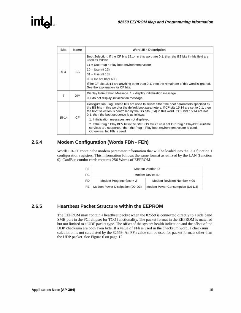
2.6.4 Modem Configuration (Words FBh - FEh)
Words FB-FE contain the modem parameter information that will be loaded into the PCI function 1 configuration registers. This information follows the same format as utilized by the LAN (function 0). CardBus combo cards requires 256 Words of EEPROM.
2.6.5 Heartbeat Packet Structure within the EEPROM
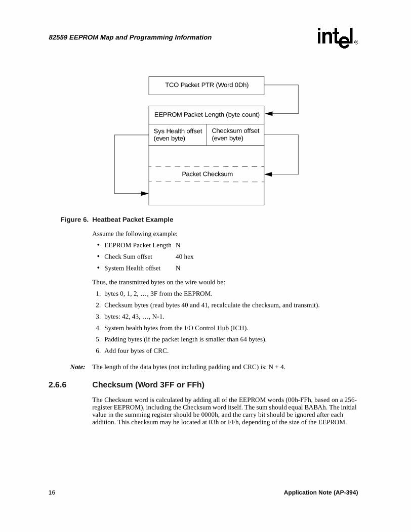
The EEPROM may contain a heartbeat packet when the 82559 is connected directly to a side band SMB port in the PCI chipset for TCO functionality. The packet format in the EEPROM is matched but not limited to a UDP packet type. The offset of the system health indication and the offset of the UDP checksum are both even byte. If a value of FFh is used in the checksum word, a checksum calculation is not calculated by the 82559. An FFh value can be used for packet formats other than the UDP packet. See Figure 6 on page 12.
Bits Name Word 3Bh Description
5-4 BS
Boot Selection. If the CF bits 15:14 in this word are 0:1, then the BS bits in this field are used as follows:
11 = Use Plug n Play boot environment vector
10 = Use Int 19h
01 = Use Int 18h
00 = Do not boot NIC.
If the CF bits 15:14 are anything other than 0:1, then the remainder of this word is ignored. See the explanation for CF bits.
7 DIM Display Initialization Message. 1 = display initialization message.
0 = do not display initialization message.
15-14 CF
Configuration Flag. These bits are used to select either the boot parameters specified by the BS bits in this word or the default boot parameters. If CF bits 15:14 are set to 0:1, then the boot selection is controlled by the BS bits (5:4) in this word. If CF bits 15:14 are not 0:1, then the boot sequence is as follows:
1. Initialization messages are not displayed.
2. If the Plug n Play BEV bit in the SMBIOS structure is set OR Plug n Play/BBS runtime services are supported, then the Plug n Play boot environment vector is used. Otherwise, Int 18h is used.
FB Modem Vendor ID
FC Modem Device ID
FD Modem Prog Interface = 2 Modem Revision Number = 00
FE Modem Power Dissipation (D0-D3) Modem Power Consumption (D0-D3)
Application Note (AP-394) 15
82559 EEPROM Map and Programming Information
Figure 6. Heatbeat Packet Example
Assume the following example:
• EEPROM Packet Length N
• Check Sum offset 40 hex
• System Health offset N
Thus, the transmitted bytes on the wire would be:
1. bytes 0, 1, 2, …, 3F from the EEPROM.
2. Checksum bytes (read bytes 40 and 41, recalculate the checksum, and transmit).
3. bytes: 42, 43, …, N-1.
4. System health bytes from the I/O Control Hub (ICH).
5. Padding bytes (if the packet length is smaller than 64 bytes).
6. Add four bytes of CRC.
Note: The length of the data bytes (not including padding and CRC) is: N + 4.
2.6.6 Checksum (Word 3FF or FFh)
The Checksum word is calculated by adding all of the EEPROM words (00h-FFh, based on a 256-register EEPROM), including the Checksum word itself. The sum should equal BABAh. The initial value in the summing register should be 0000h, and the carry bit should be ignored after each addition. This checksum may be located at 03h or FFh, depending of the size of the EEPROM.
TCO Packet PTR (Word 0Dh)
EEPROM Packet Length (byte count)
Sys Health offset(even byte)
Checksum offset(even byte)
Packet Checksum
16 Application Note (AP-394)
82559ER EEPROM Map and Programming Information
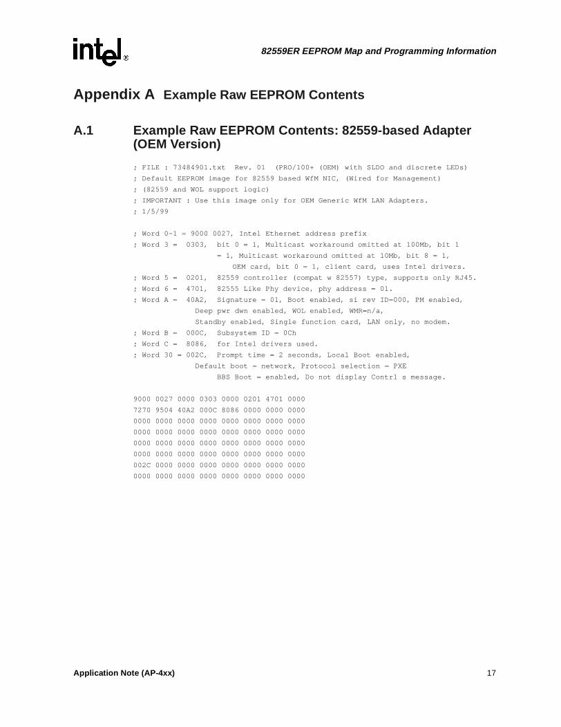
Appendix A Example Raw EEPROM Contents
A.1 Example Raw EEPROM Contents: 82559-based Adapter (OEM Version)
; FILE : 73484901.txt Rev. 01 (PRO/100+ (OEM) with SLDO and discrete LEDs)
; Default EEPROM image for 82559 based WfM NIC, (Wired for Management)
; (82559 and WOL support logic)
; IMPORTANT : Use this image only for OEM Generic WfM LAN Adapters.
; 1/5/99
; Word 0-1 = 9000 0027, Intel Ethernet address prefix
; Word 3 = 0303, bit 0 = 1, Multicast workaround omitted at 100Mb, bit 1
= 1, Multicast workaround omitted at 10Mb, bit 8 = 1,
OEM card, bit 0 = 1, client card, uses Intel drivers.
; Word 5 = 0201, 82559 controller (compat w 82557) type, supports only RJ45.
; Word 6 = 4701, 82555 Like Phy device, phy address = 01.
; Word A = 40A2, Signature = 01, Boot enabled, si rev ID=000, PM enabled,
Deep pwr dwn enabled, WOL enabled, WMR=n/a,
Standby enabled, Single function card, LAN only, no modem.
; Word B = 000C, Subsystem ID = 0Ch
; Word C = 8086, for Intel drivers used.
; Word 30 = 002C, Prompt time = 2 seconds, Local Boot enabled,
Default boot = network, Protocol selection = PXE
BBS Boot = enabled, Do not display Contrl s message.
9000 0027 0000 0303 0000 0201 4701 0000
7270 9504 40A2 000C 8086 0000 0000 0000
0000 0000 0000 0000 0000 0000 0000 0000
0000 0000 0000 0000 0000 0000 0000 0000
0000 0000 0000 0000 0000 0000 0000 0000
0000 0000 0000 0000 0000 0000 0000 0000
002C 0000 0000 0000 0000 0000 0000 0000
0000 0000 0000 0000 0000 0000 0000 0000
Application Note (AP-4xx) 17