Embed Size (px)
Citation preview
https://support.industry.siemens.com/cs/ww/en/view/62121503
Application Example 07/2016
Configuring Messages and Alarms in WinCC (TIA Portal) - Extension with S7-1500 STEP 7 V13 SP1, WinCC V13 SP1 (Basic/ Comfort/ Advanced/ Professional/ Runtime Advanced/ Runtime Professional)
Warranty and Liability
Messages and Alarms in WinCC (TIA Portal) Entry-ID: 62121503, V1.0, 07/2016 2
S
iem
en
s A
G 2
01
6 A
ll ri
gh
ts r
ese
rve
d
Warranty and Liability
Note The Application Examples are not binding and do not claim to be complete with regard to configuration, equipment or any contingencies. The application examples do not represent customer-specific solutions. They are only intended to provide support for typical applications. You are responsible for the correct operation of the described products. These application examples do not relieve you of the responsibility of safely and professionally using, installing, operating and servicing equipment. When using these Application Examples, you recognize that we cannot be made liable for any damage/claims beyond the liability clause described. We reserve the right to make changes to these application examples at any time and without prior notice. If there are any deviations between the recommendations provided in this Application Example and other Siemens publications – e.g. Catalogs – the contents of the other documents shall have priority.
We do not accept any liability for the information contained in this document. Any claims against us – based on whatever legal reason – resulting from the use of the examples, information, programs, engineering and performance data etc., described in this Application Example shall be excluded. Such an exclusion shall not apply in the case of mandatory liability, e.g. under the German Product Liability Act (“Produkthaftungsgesetz”), in case of intent, gross negligence, or injury of life, body or health, guarantee for the quality of a product, fraudulent concealment of a deficiency or breach of fundamental contractual obligations (“wesentliche Vertragspflichten”). The damages for a breach of a substantial contractual obligation are, however, limited to the foreseeable damage, typical for the type of contract, except in the event of intent or gross negligence or injury to life, body or health. The above provisions do not imply a change of the burden of proof to your detriment. Any form of duplication or distribution of these Application Examples or excerpts hereof is prohibited without the expressed consent of Siemens AG.
Security informa-
tion
Siemens provides products and solutions with industrial security functions that support the secure operation of plants, systems, machines and networks.
In order to secure plants, systems, machines and networks against cyber threats, it is necessary to implement (and continuously maintain) a holistic, state-of-the-art industrial security concept. With this in mind, Siemens’ products and solutions are only part of such a concept.
It is the client’s responsibility to prevent unauthorized access to his plants, systems, machines and networks. Systems, machines and components should only be connected with the company’s network or the Internet, when and insofar as this is required and the appropriate protective measures (for example, use of firewalls and network segmentation) have been taken.
In addition, the recommendations by Siemens regarding the respective protective measures have to be observed. For more information on industrial security, visit http://www.siemens.com/industrialsecurity.
Siemens’ products and solutions undergo continuous development in order to make them even more secure. Siemens explicitly recommends to carry out updates as soon as the respective updates are available and always only to use the current product versions. Use of product versions that are no longer supported, and failure to apply latest updates may increase customer’s exposure to cyber threats.
In order to always be informed about product updates, subscribe to the Siemens Industrial Security RSS Feed at http://www.siemens.com/industrialsecurity.
Table of Contents
Messages and Alarms in WinCC (TIA Portal) Entry-ID: 62121503, V1.0, 07/2016 3
S
iem
en
s A
G 2
01
6 A
ll ri
gh
ts r
ese
rve
d
Table of Contents Warranty and Liability ................................................................................................. 2
1 Task ..................................................................................................................... 4
1.1 Introduction ........................................................................................... 4 1.2 Scope ................................................................................................... 4
2 Solution............................................................................................................... 5
2.1 Overview............................................................................................... 5 2.2 Hardware and software components ................................................... 5
3 Fundamentals .................................................................................................... 6
3.1 Overview of the alarm procedures ....................................................... 6 3.2 User-defined alarms ............................................................................. 7 3.3 System-defined alarms ......................................................................... 8 3.4 Availability of alarm procedures ........................................................... 9
4 Configuring alarms in WinCC Basic/Comfort/Advanced ............................. 10
4.1 Configuring user-defined alarms ........................................................ 10 4.2 Configuring system-defined alarms .................................................... 11 4.2.1 Configuring system events ................................................................. 11 4.2.2 Configuring CPU system diagnostics alarms ..................................... 15 4.3 Configuring controller alarms ............................................................. 18 4.3.1 Configuring Program_Alarm ............................................................... 18 4.3.2 Configuring Get_AlarmState .............................................................. 25 4.3.3 Configuring Gen_UsrMsg ................................................................... 29 4.4 Using alarm classes ........................................................................... 33 4.5 Using alarm groups ............................................................................ 34 4.6 The acknowledgment types ............................................................... 35
5 Configuring alarms in WinCC Professional .................................................. 37
5.1 Configuring user-defined alarms ........................................................ 37 5.2 Configuring system-defined alarms .................................................... 37 5.2.1 Configuring system alarms ................................................................. 37 5.2.2 Configuring CPU system diagnostics alarms ..................................... 42 5.3 Configuring controller alarms ............................................................. 43 5.3.1 Configuring Program_Alarm ............................................................... 43 5.3.2 Configuring Get_AlarmState .............................................................. 45 5.3.3 Configuring Gen_UsrMsg ................................................................... 45 5.4 Using alarm classes in WinCC Professional ...................................... 45 5.5 Using alarm groups in WinCC Professional ....................................... 47 5.6 The acknowledgment types in WinCC Professional .......................... 48 5.6.1 Alarm without acknowledgment ......................................................... 48 5.6.2 Alarm with simple acknowledgment ................................................... 48 5.6.3 Alarm with double acknowledgment ................................................... 50 5.6.4 General information on acknowledgment types ................................. 51
6 References ....................................................................................................... 52
7 History............................................................................................................... 52

1 Task
1.1 Introduction
Messages and Alarms in WinCC (TIA Portal) Entry-ID: 62121503, V1.0, 07/2016 4
S
iem
en
s A
G 2
01
6 A
ll ri
gh
ts r
ese
rve
d
1 Task
1.1 Introduction
During a plant’s process, it is essential to visually output information on operating states, malfunctions and individual processes to an HMI operating panel. In connection with the S7-1500 SIMATIC Advanced Controllers, the WinCC (TIA Portal) alarm system provides an alarm procedure for each of these information.
In this application, you get:
An overview of the various alarm procedures in WinCC
Support in choosing the correct alarm procedure for your application and your existing hardware (S7-1200/1500)
Detailed configuration instructions of the different alarm types in WinCC (TIA Portal) and STEP 7 Professional
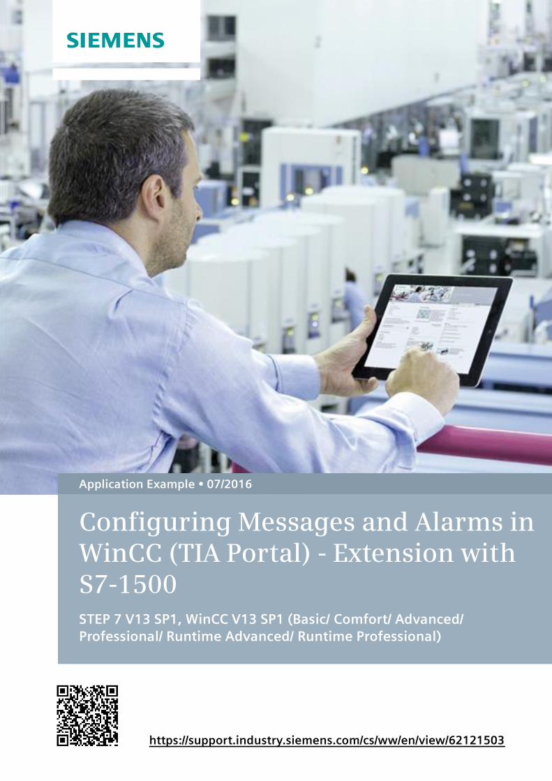
Figure 1-1
PROFINET / IE
S7-1500
TP1200
e.g. ET200 SP
Message
1.2 Scope
In this application example, messages and alarms in WinCC (TIA Portal) are described in connection with the S7-1500 controller family. Further information on the alarm procedures with the S7-300/400 controllers can be found in the second PDF document for this application example.

2 Solution
2.1 Overview
Messages and Alarms in WinCC (TIA Portal) Entry-ID: 62121503, V1.0, 07/2016 5
S
iem
en
s A
G 2
01
6 A
ll ri
gh
ts r
ese
rve
d
2 Solution
2.1 Overview
Main topics of this application
In this application example, the configuration of messages and alarms in WinCC (TIA Portal) is described in connection with the S7-1500 controller family. In essence, controller-specific alarms and messages are elaborated upon and further described.
The starting point of this application is the application example “Configuring messages and alarms in WinCC (TIA Portal)” in connection with the S7-300/400 controller family. The fundamentals as well as specific chapters explicitly refer to this application example since it has the same content and configuration scope. Furthermore, this application example also serves as additional help to the TIA Portal’s manual and online help.
2.2 Hardware and software components
The application was created with the following components:
Hardware components
Table 2-1
Component Qty Article number Note
SIMATIC CPU 1513-1 PN 1 6ES7513-1AL01-0AB0 Alternatively, every other CPU from the S7-1500 family may be used, you simply need to exchange the device in the configuration.
Memory Card 24 MByte 1 6ES7954-8FL02-0AA0
SIMATIC HMI TP1200 Comfort
1 6AV2124-0MC01-0AX0 Alternatively, any other Comfort Panel may also be used (device exchange required).
Software components
Table 2-2
Component Qty Article number Note
STEP 7 Professional V13 SP1
1 6ES7822-1..03
WinCC Professional V13 SP1
1 6AV210.-…3-0
WinCC Runtime Professional V13 SP1
1 6AV2105-0…-….
3 Fundamentals
3.1 Overview of the alarm procedures
Messages and Alarms in WinCC (TIA Portal) Entry-ID: 62121503, V1.0, 07/2016 6
S
iem
en
s A
G 2
01
6 A
ll ri
gh
ts r
ese
rve
d
3 Fundamentals
3.1 Overview of the alarm procedures
Introduction
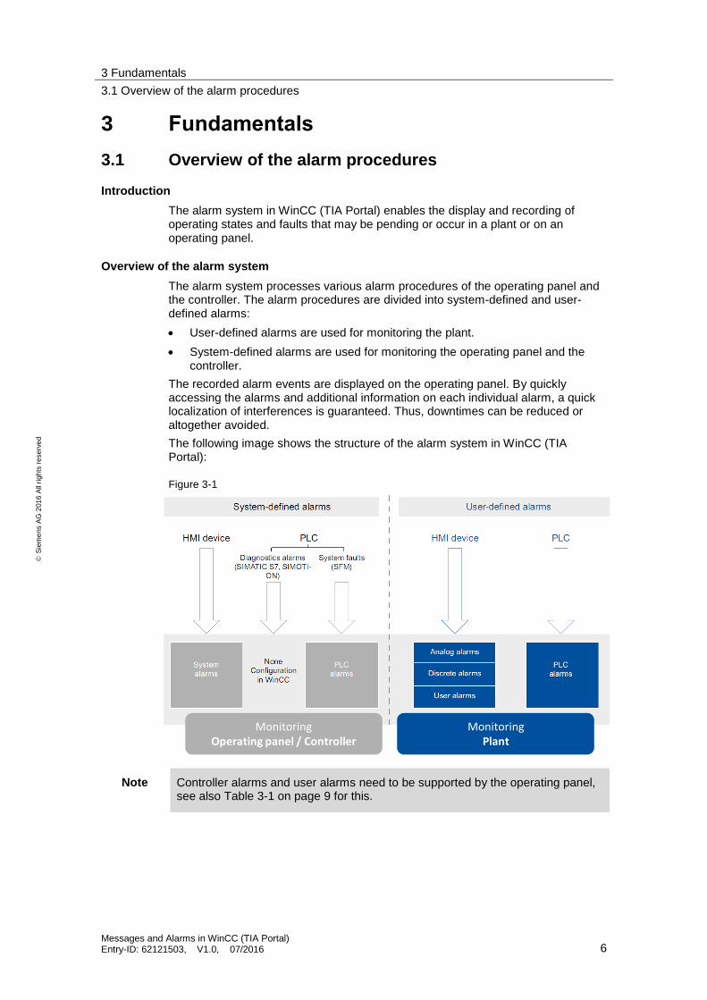
The alarm system in WinCC (TIA Portal) enables the display and recording of operating states and faults that may be pending or occur in a plant or on an operating panel.
Overview of the alarm system
The alarm system processes various alarm procedures of the operating panel and the controller. The alarm procedures are divided into system-defined and user-defined alarms:
User-defined alarms are used for monitoring the plant.
System-defined alarms are used for monitoring the operating panel and the controller.
The recorded alarm events are displayed on the operating panel. By quickly accessing the alarms and additional information on each individual alarm, a quick localization of interferences is guaranteed. Thus, downtimes can be reduced or altogether avoided.
The following image shows the structure of the alarm system in WinCC (TIA Portal):
Figure 3-1
MonitoringOperating panel / Controller
MonitoringPlant
Note Controller alarms and user alarms need to be supported by the operating panel, see also Table 3-1 on page 9 for this.

3 Fundamentals
3.2 User-defined alarms
Messages and Alarms in WinCC (TIA Portal) Entry-ID: 62121503, V1.0, 07/2016 7
S
iem
en
s A
G 2
01
6 A
ll ri
gh
ts r
ese
rve
d
3.2 User-defined alarms
The user-defined alarm procedures are used for monitoring the plant procedures. They are designated according to the type of information that is required to trigger the alarm.
User-defined alarm procedures consist of the following alarms:
Analog alarms
Bit alarms
Controller alarms
User alarms
Analog alarms
An analog alarm views limit value violations of a tag during operation. An analog alarm is triggered by exceeding/falling below a previously defined limit value.
Bit alarms
A bit alarm views status changes during operation. A bit alarm is triggered by a certain value (Bit) of a tag.
Controller alarms
Controller alarms display status values of the controller during operation.
User alarms
A user alarm monitors operating actions in WinCC Runtime Professional during operation. User alarms are triggered by triggering the alarm number. A user alarm may, for example, contain the following information:
• Type and content of the acknowledged alarm
• Time of acknowledgment
• User
• Date
Note Device dependence
Controller alarms and user alarms are not available for all operating panels.
3 Fundamentals
3.3 System-defined alarms
Messages and Alarms in WinCC (TIA Portal) Entry-ID: 62121503, V1.0, 07/2016 8
S
iem
en
s A
G 2
01
6 A
ll ri
gh
ts r
ese
rve
d
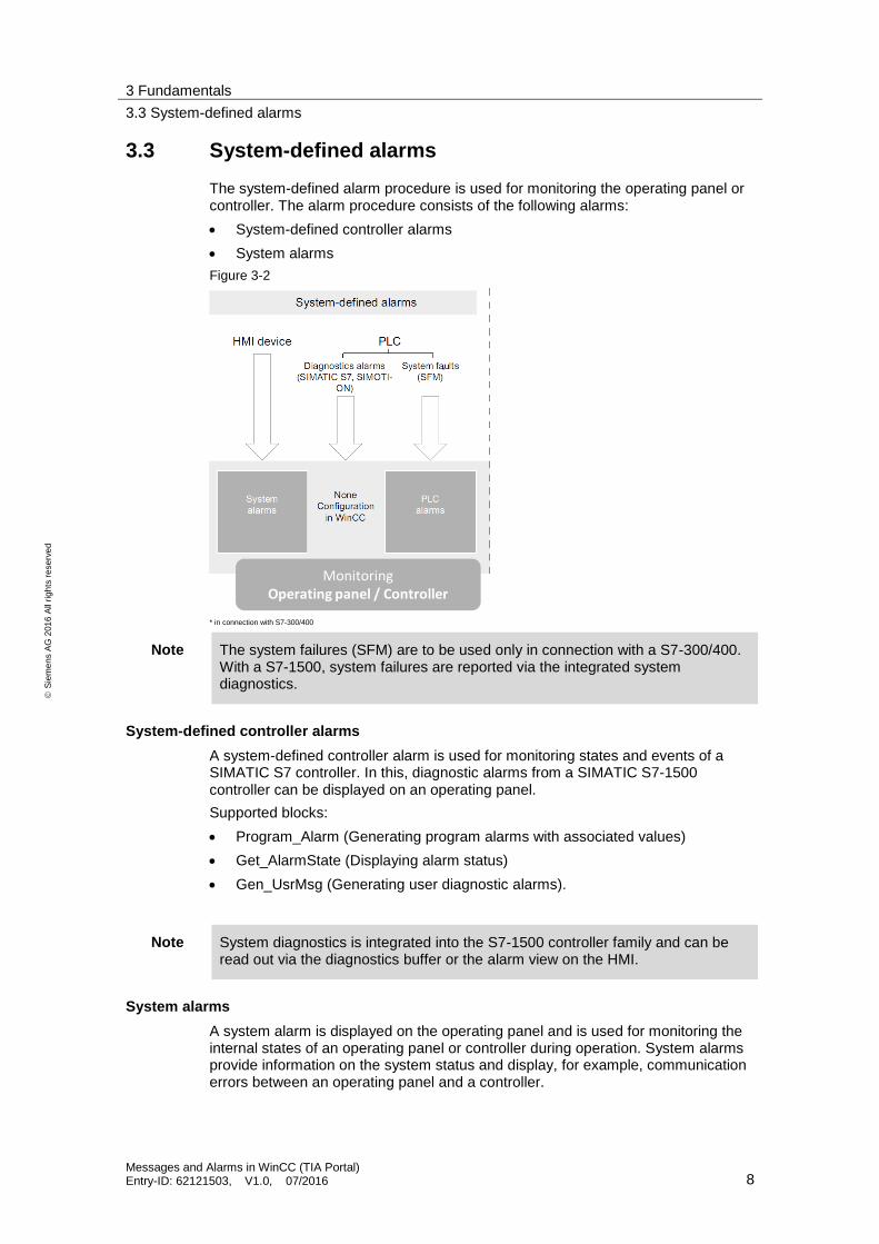
3.3 System-defined alarms
The system-defined alarm procedure is used for monitoring the operating panel or controller. The alarm procedure consists of the following alarms:
System-defined controller alarms
System alarms
Figure 3-2
MonitoringOperating panel / Controller
MonitoringPlant
* in connection with S7-300/400
Note The system failures (SFM) are to be used only in connection with a S7-300/400. With a S7-1500, system failures are reported via the integrated system diagnostics.
System-defined controller alarms
A system-defined controller alarm is used for monitoring states and events of a SIMATIC S7 controller. In this, diagnostic alarms from a SIMATIC S7-1500 controller can be displayed on an operating panel.
Supported blocks:
Program_Alarm (Generating program alarms with associated values)
Get_AlarmState (Displaying alarm status)
Gen_UsrMsg (Generating user diagnostic alarms).
Note System diagnostics is integrated into the S7-1500 controller family and can be read out via the diagnostics buffer or the alarm view on the HMI.
System alarms
A system alarm is displayed on the operating panel and is used for monitoring the internal states of an operating panel or controller during operation. System alarms provide information on the system status and display, for example, communication errors between an operating panel and a controller.
*
3 Fundamentals
3.4 Availability of alarm procedures
Messages and Alarms in WinCC (TIA Portal) Entry-ID: 62121503, V1.0, 07/2016 9
S
iem
en
s A
G 2
01
6 A
ll ri
gh
ts r
ese
rve
d
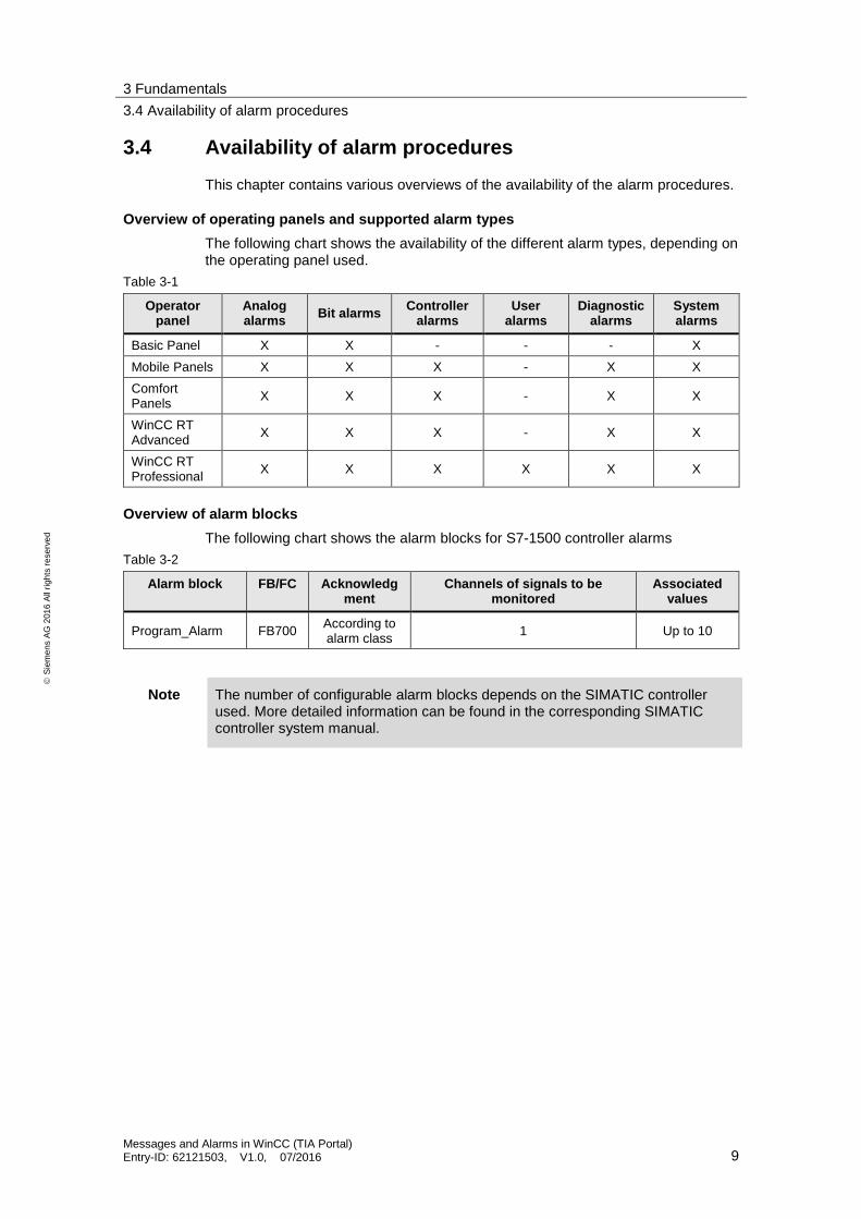
3.4 Availability of alarm procedures
This chapter contains various overviews of the availability of the alarm procedures.
Overview of operating panels and supported alarm types
The following chart shows the availability of the different alarm types, depending on the operating panel used.
Table 3-1
Operator panel
Analog alarms
Bit alarms Controller
alarms User
alarms Diagnostic
alarms System alarms
Basic Panel X X - - - X
Mobile Panels X X X - X X
Comfort Panels
X X X - X X
WinCC RT Advanced
X X X - X X
WinCC RT Professional
X X X X X X
Overview of alarm blocks
The following chart shows the alarm blocks for S7-1500 controller alarms
Table 3-2
Alarm block FB/FC Acknowledgment
Channels of signals to be monitored
Associated values
Program_Alarm FB700 According to alarm class
1 Up to 10
Note The number of configurable alarm blocks depends on the SIMATIC controller used. More detailed information can be found in the corresponding SIMATIC controller system manual.
4 Configuring alarms in WinCC Basic/Comfort/Advanced
4.1 Configuring user-defined alarms
Messages and Alarms in WinCC (TIA Portal) Entry-ID: 62121503, V1.0, 07/2016 10
S
iem
en
s A
G 2
01
6 A
ll ri
gh
ts r
ese
rve
d
4 Configuring alarms in WinCC Basic/Comfort/Advanced In addition to the manual (chapter “Working with alarms”), this section essentially describes how to configure system-defined alarms and controller alarms. For the sake of completeness, the configuration of user-defined alarms is also described.
Required software components
WinCC Basic/Comfort/Advanced V13 SP1
STEP 7 Professional V13 SP1
Prerequisite
There already is an existing WinCC (TIA Portal) project with an established connection between the operating panel and the controller.
4.1 Configuring user-defined alarms
In WinCC Basic/Comfort/Advanced, the configuration of user-defined alarms (bit alarms and analog alarms) is independent from the controller used. A detailed description on how to configure user-defined alarms can be found in the application example ”Configuring messages and alarms in WinCC (TIA Portal)“. Complete descriptions can also be found in the WinCC Advanced V13 SP1 system manual under the chapters “Configuring discrete alarms“ and “Configuring analog alarms“ .

4 Configuring alarms in WinCC Basic/Comfort/Advanced
4.2 Configuring system-defined alarms
Messages and Alarms in WinCC (TIA Portal) Entry-ID: 62121503, V1.0, 07/2016 11
S
iem
en
s A
G 2
01
6 A
ll ri
gh
ts r
ese
rve
d
4.2 Configuring system-defined alarms
4.2.1 Configuring system events
By default, system events are stored in various languages in the HMI. If you want to translate system events into further languages, the texts first have to be imported into the project.
Importing system events
Importing system events is only necessary for projects that have been newly created, or if system events have not been imported yet.
Table 4-1
No. Action
1. In the project navigation in the folder of your created operating panel, open “HMI alarms”.
2. Open the “System events” tab.
3. Confirm the following dialog to import the “System events”.
4. Importing the system events is now complete.
4 Configuring alarms in WinCC Basic/Comfort/Advanced
4.2 Configuring system-defined alarms
Messages and Alarms in WinCC (TIA Portal) Entry-ID: 62121503, V1.0, 07/2016 12
S
iem
en
s A
G 2
01
6 A
ll ri
gh
ts r
ese
rve
d
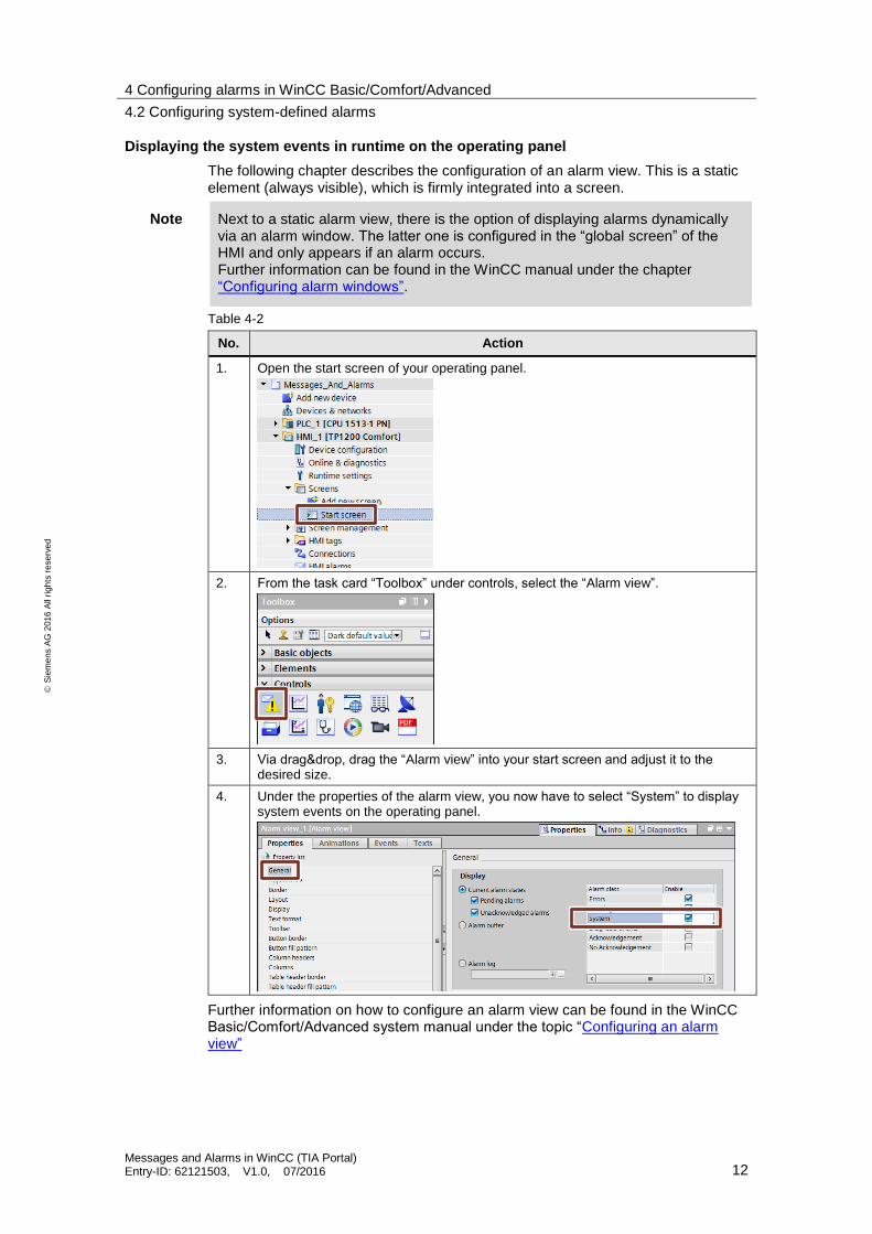
Displaying the system events in runtime on the operating panel
The following chapter describes the configuration of an alarm view. This is a static element (always visible), which is firmly integrated into a screen.
Note Next to a static alarm view, there is the option of displaying alarms dynamically via an alarm window. The latter one is configured in the “global screen” of the HMI and only appears if an alarm occurs. Further information can be found in the WinCC manual under the chapter “Configuring alarm windows”.
Table 4-2
No. Action
1. Open the start screen of your operating panel.
2. From the task card “Toolbox” under controls, select the “Alarm view”.
3. Via drag&drop, drag the “Alarm view” into your start screen and adjust it to the desired size.
4. Under the properties of the alarm view, you now have to select “System” to display system events on the operating panel.
Further information on how to configure an alarm view can be found in the WinCC Basic/Comfort/Advanced system manual under the topic “Configuring an alarm view”

4 Configuring alarms in WinCC Basic/Comfort/Advanced
4.2 Configuring system-defined alarms
Messages and Alarms in WinCC (TIA Portal) Entry-ID: 62121503, V1.0, 07/2016 13
S
iem
en
s A
G 2
01
6 A
ll ri
gh
ts r
ese
rve
d
Defining the display time for system events
Table 4-3
No. Action
1. In the project navigation in the folder of your created operating panel, open the “Runtime settings”.
2. Open the “Alarms” menu.
Under “System events > display duration in seconds”, enter a display duration for the system events into the operating panel.
Note
If you want the system events to be displayed permanently, select a display duration of “0” seconds.
3. Setting the display duration for system events is now complete.

4 Configuring alarms in WinCC Basic/Comfort/Advanced
4.2 Configuring system-defined alarms
Messages and Alarms in WinCC (TIA Portal) Entry-ID: 62121503, V1.0, 07/2016 14
S
iem
en
s A
G 2
01
6 A
ll ri
gh
ts r
ese
rve
d
Changing alarms texts for system events
The alarm texts of the system events can be changed or adjusted, if needed. The corresponding alarm numbers are not changeable.
NOTICE Changing the system events means changing clearly defined events which may lead to misinterpretations. The imported events are part of the manual and the online help. A change would mean that the altered events no longer correspond with the documentation.
Table 4-4
No. Action
1. In the project navigation in the folder of your created operating panel, open “HMI alarms”.
2. Open the “System events” tab.
Mark the system events whose alarm text is to be changed.
4 Configuring alarms in WinCC Basic/Comfort/Advanced
4.2 Configuring system-defined alarms
Messages and Alarms in WinCC (TIA Portal) Entry-ID: 62121503, V1.0, 07/2016 15
S
iem
en
s A
G 2
01
6 A
ll ri
gh
ts r
ese
rve
d
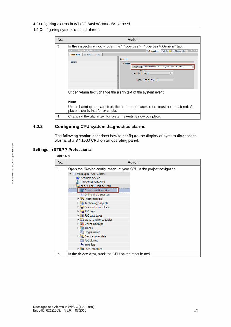
No. Action
3. In the inspector window, open the “Properties > Properties > General” tab.
Under “Alarm text”, change the alarm text of the system event.
Note
Upon changing an alarm text, the number of placeholders must not be altered. A placeholder is %1, for example.
4. Changing the alarm text for system events is now complete.
4.2.2 Configuring CPU system diagnostics alarms
The following section describes how to configure the display of system diagnostics alarms of a S7-1500 CPU on an operating panel.
Settings in STEP 7 Professional
Table 4-5
No. Action
1. Open the “Device configuration” of your CPU in the project navigation.
2. In the device view, mark the CPU on the module rack.
4 Configuring alarms in WinCC Basic/Comfort/Advanced
4.2 Configuring system-defined alarms
Messages and Alarms in WinCC (TIA Portal) Entry-ID: 62121503, V1.0, 07/2016 16
S
iem
en
s A
G 2
01
6 A
ll ri
gh
ts r
ese
rve
d
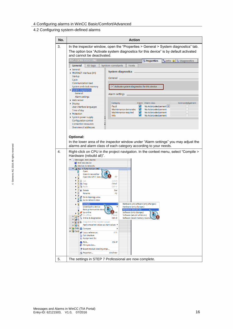
No. Action
3. In the inspector window, open the “Properties > General > System diagnostics” tab.
The option box “Activate system diagnostics for this device” is by default activated and cannot be deactivated.
Optional:
In the lower area of the inspector window under “Alarm settings” you may adjust the alarms and alarm class of each category according to your needs.
4. Right-click on CPU in the project navigation. In the context menu, select “Compile > Hardware (rebuild all)”.
5. The settings in STEP 7 Professional are now complete.
4 Configuring alarms in WinCC Basic/Comfort/Advanced
4.2 Configuring system-defined alarms
Messages and Alarms in WinCC (TIA Portal) Entry-ID: 62121503, V1.0, 07/2016 17
S
iem
en
s A
G 2
01
6 A
ll ri
gh
ts r
ese
rve
d
Settings in WinCC Basic/Comfort/Advanced
Table 4-6
No. Action
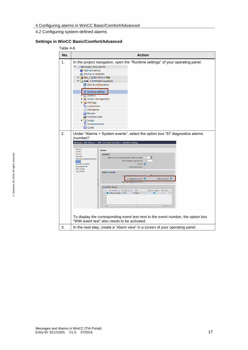
1. In the project navigation, open the “Runtime settings” of your operating panel.
2. Under “Alarms > System events”, select the option box “S7 diagnostics alarms (number)”.
To display the corresponding event text next to the event number, the option box “With event text” also needs to be activated.
3. In the next step, create a “Alarm view” in a screen of your operating panel.
4 Configuring alarms in WinCC Basic/Comfort/Advanced
4.3 Configuring controller alarms
Messages and Alarms in WinCC (TIA Portal) Entry-ID: 62121503, V1.0, 07/2016 18
S
iem
en
s A
G 2
01
6 A
ll ri
gh
ts r
ese
rve
d
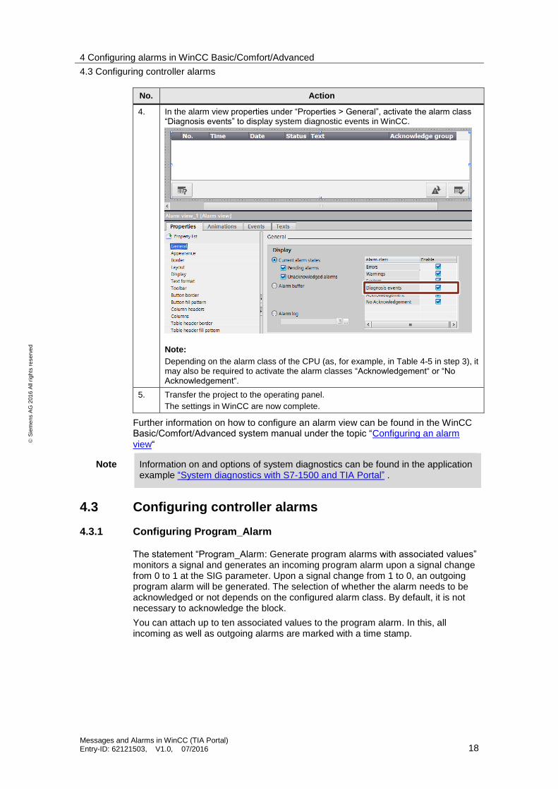
No. Action
4. In the alarm view properties under “Properties > General”, activate the alarm class “Diagnosis events” to display system diagnostic events in WinCC.
Note:
Depending on the alarm class of the CPU (as, for example, in Table 4-5 in step 3), it may also be required to activate the alarm classes “Acknowledgement“ or “No Acknowledgement“.
5. Transfer the project to the operating panel.
The settings in WinCC are now complete.
Further information on how to configure an alarm view can be found in the WinCC Basic/Comfort/Advanced system manual under the topic “Configuring an alarm view“
Note Information on and options of system diagnostics can be found in the application example “System diagnostics with S7-1500 and TIA Portal” .
4.3 Configuring controller alarms
4.3.1 Configuring Program_Alarm
The statement “Program_Alarm: Generate program alarms with associated values” monitors a signal and generates an incoming program alarm upon a signal change from 0 to 1 at the SIG parameter. Upon a signal change from 1 to 0, an outgoing program alarm will be generated. The selection of whether the alarm needs to be acknowledged or not depends on the configured alarm class. By default, it is not necessary to acknowledge the block.
You can attach up to ten associated values to the program alarm. In this, all incoming as well as outgoing alarms are marked with a time stamp.
4 Configuring alarms in WinCC Basic/Comfort/Advanced
4.3 Configuring controller alarms
Messages and Alarms in WinCC (TIA Portal) Entry-ID: 62121503, V1.0, 07/2016 19
S
iem
en
s A
G 2
01
6 A
ll ri
gh
ts r
ese
rve
d
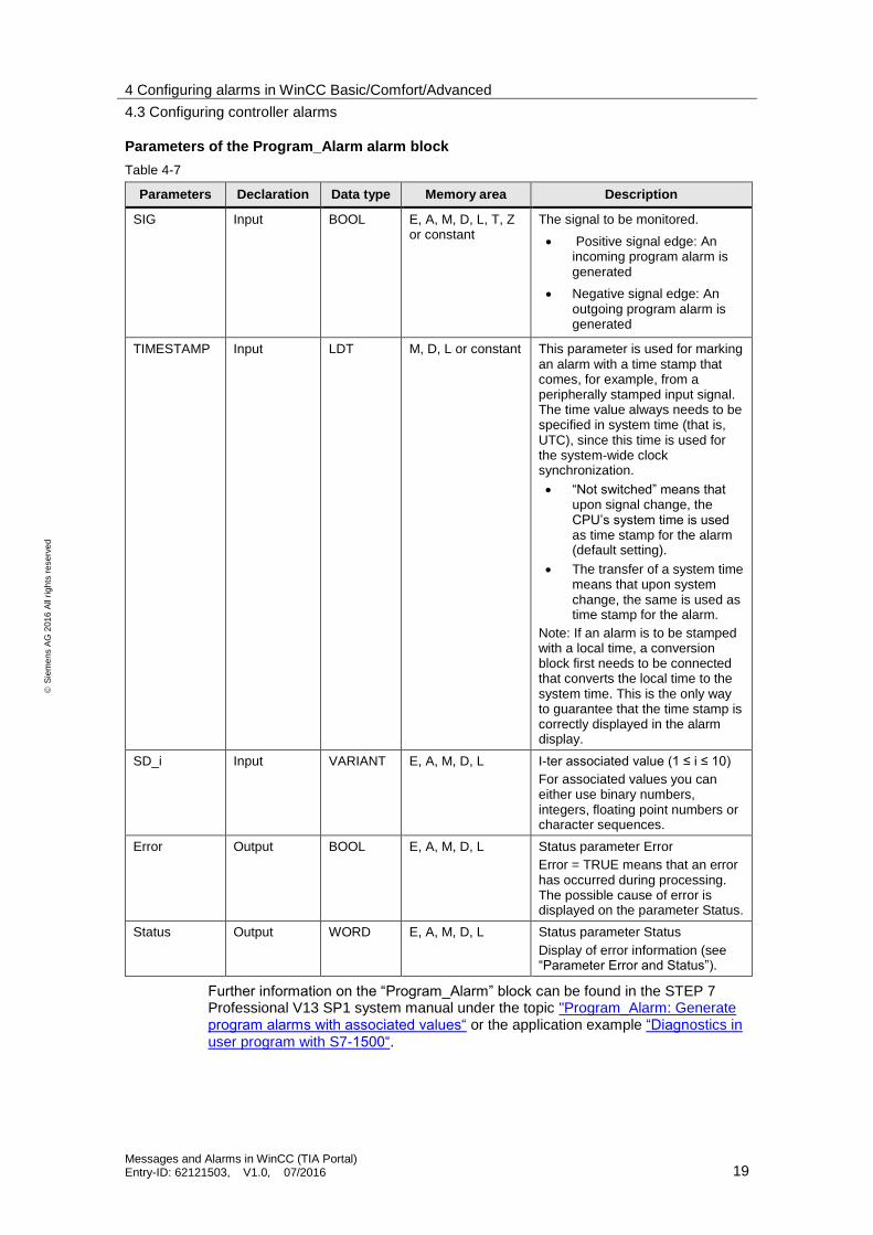
Parameters of the Program_Alarm alarm block
Table 4-7
Parameters Declaration Data type Memory area Description
SIG Input BOOL E, A, M, D, L, T, Z or constant
The signal to be monitored.
Positive signal edge: An incoming program alarm is generated
Negative signal edge: An outgoing program alarm is generated
TIMESTAMP Input LDT M, D, L or constant This parameter is used for marking an alarm with a time stamp that comes, for example, from a peripherally stamped input signal. The time value always needs to be specified in system time (that is, UTC), since this time is used for the system-wide clock synchronization.
“Not switched” means that upon signal change, the CPU’s system time is used as time stamp for the alarm (default setting).
The transfer of a system time means that upon system change, the same is used as time stamp for the alarm.
Note: If an alarm is to be stamped with a local time, a conversion block first needs to be connected that converts the local time to the system time. This is the only way to guarantee that the time stamp is correctly displayed in the alarm display.
SD_i Input VARIANT E, A, M, D, L I-ter associated value (1 ≤ i ≤ 10)
For associated values you can either use binary numbers, integers, floating point numbers or character sequences.
Error Output BOOL E, A, M, D, L Status parameter Error
Error = TRUE means that an error has occurred during processing. The possible cause of error is displayed on the parameter Status.
Status Output WORD E, A, M, D, L Status parameter Status
Display of error information (see “Parameter Error and Status”).
Further information on the “Program_Alarm” block can be found in the STEP 7 Professional V13 SP1 system manual under the topic "Program_Alarm: Generate program alarms with associated values“ or the application example “Diagnostics in user program with S7-1500“.
4 Configuring alarms in WinCC Basic/Comfort/Advanced
4.3 Configuring controller alarms
Messages and Alarms in WinCC (TIA Portal) Entry-ID: 62121503, V1.0, 07/2016 20
S
iem
en
s A
G 2
01
6 A
ll ri
gh
ts r
ese
rve
d
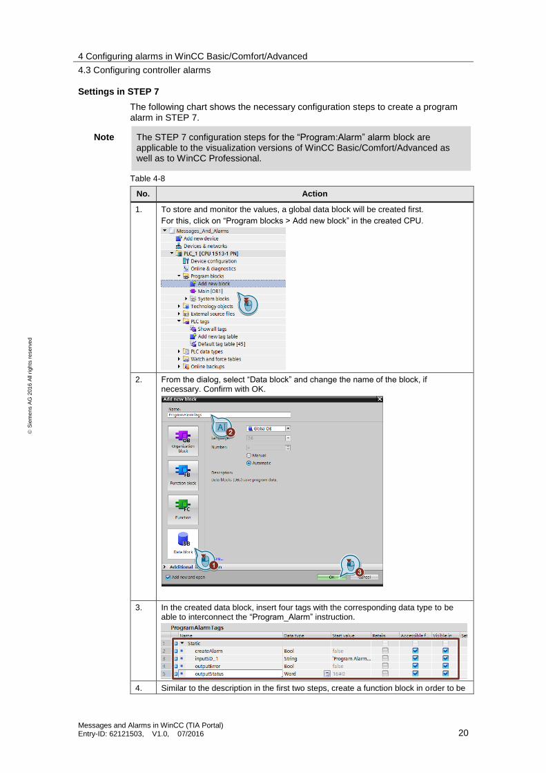
Settings in STEP 7
The following chart shows the necessary configuration steps to create a program alarm in STEP 7.
Note The STEP 7 configuration steps for the “Program:Alarm” alarm block are applicable to the visualization versions of WinCC Basic/Comfort/Advanced as well as to WinCC Professional.
Table 4-8
No. Action
1. To store and monitor the values, a global data block will be created first.
For this, click on “Program blocks > Add new block” in the created CPU.
2. From the dialog, select “Data block” and change the name of the block, if necessary. Confirm with OK.
3. In the created data block, insert four tags with the corresponding data type to be able to interconnect the “Program_Alarm” instruction.
4. Similar to the description in the first two steps, create a function block in order to be
4 Configuring alarms in WinCC Basic/Comfort/Advanced
4.3 Configuring controller alarms
Messages and Alarms in WinCC (TIA Portal) Entry-ID: 62121503, V1.0, 07/2016 21
S
iem
en
s A
G 2
01
6 A
ll ri
gh
ts r
ese
rve
d
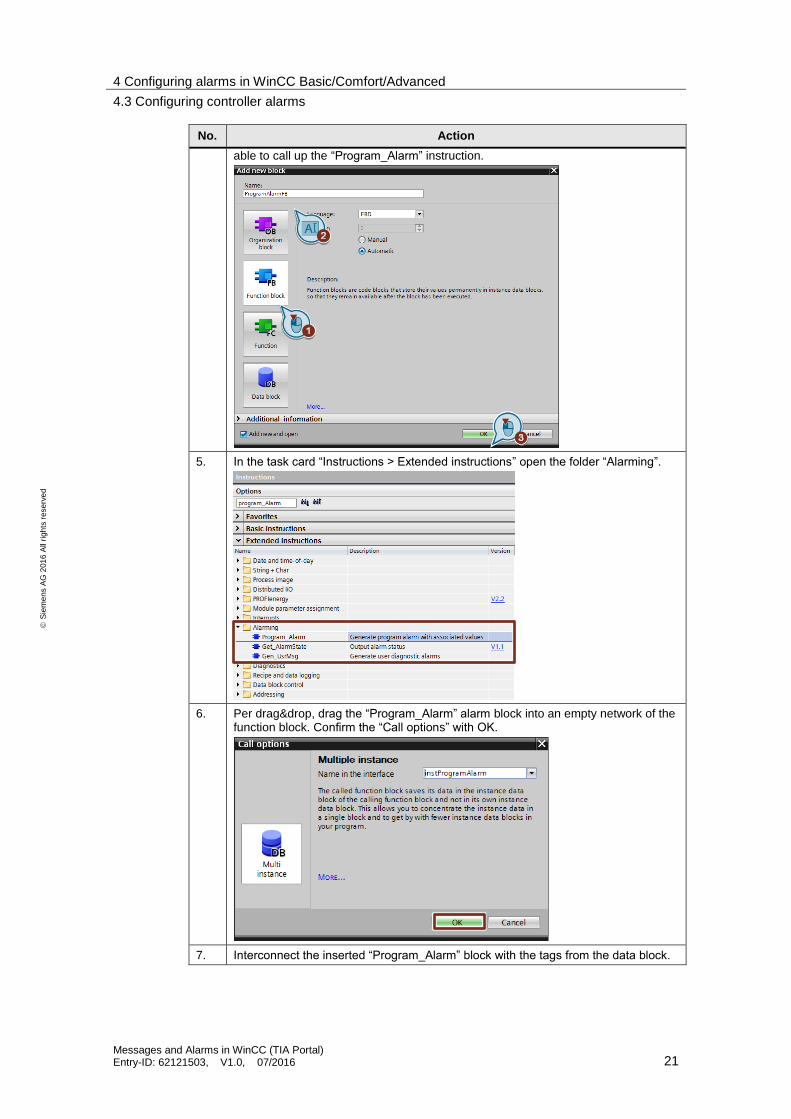
No. Action
able to call up the “Program_Alarm” instruction.
5. In the task card “Instructions > Extended instructions” open the folder “Alarming”.
6. Per drag&drop, drag the “Program_Alarm” alarm block into an empty network of the function block. Confirm the “Call options” with OK.
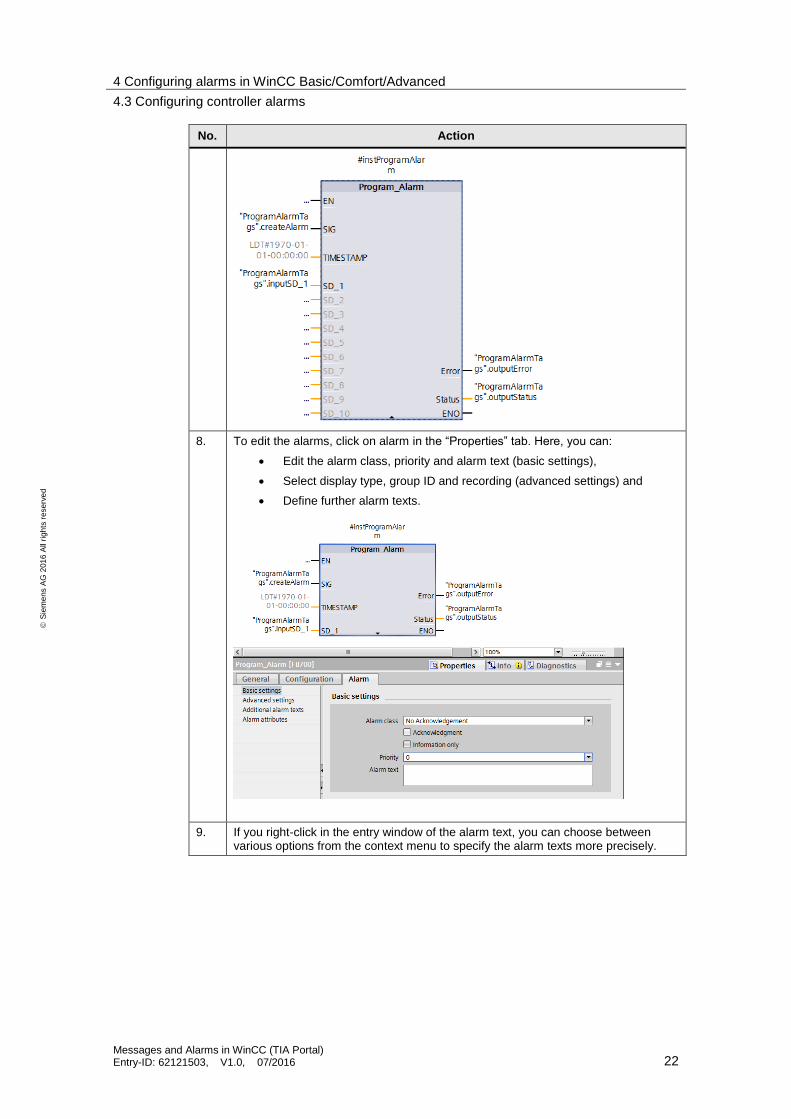
7. Interconnect the inserted “Program_Alarm” block with the tags from the data block.
4 Configuring alarms in WinCC Basic/Comfort/Advanced
4.3 Configuring controller alarms
Messages and Alarms in WinCC (TIA Portal) Entry-ID: 62121503, V1.0, 07/2016 22
S
iem
en
s A
G 2
01
6 A
ll ri
gh
ts r
ese
rve
d
No. Action
8. To edit the alarms, click on alarm in the “Properties” tab. Here, you can:
Edit the alarm class, priority and alarm text (basic settings),
Select display type, group ID and recording (advanced settings) and
Define further alarm texts.
9. If you right-click in the entry window of the alarm text, you can choose between various options from the context menu to specify the alarm texts more precisely.
4 Configuring alarms in WinCC Basic/Comfort/Advanced
4.3 Configuring controller alarms
Messages and Alarms in WinCC (TIA Portal) Entry-ID: 62121503, V1.0, 07/2016 23
S
iem
en
s A
G 2
01
6 A
ll ri
gh
ts r
ese
rve
d
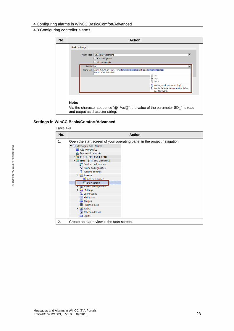
No. Action
Note:
Via the character sequence “@1%s@“, the value of the parameter SD_1 is read and output as character string.
Settings in WinCC Basic/Comfort/Advanced
Table 4-9
No. Action
1. Open the start screen of your operating panel in the project navigation.
2. Create an alarm view in the start screen.
4 Configuring alarms in WinCC Basic/Comfort/Advanced
4.3 Configuring controller alarms
Messages and Alarms in WinCC (TIA Portal) Entry-ID: 62121503, V1.0, 07/2016 24
S
iem
en
s A
G 2
01
6 A
ll ri
gh
ts r
ese
rve
d
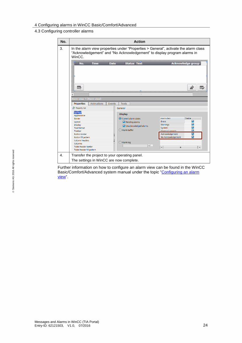
No. Action
3. In the alarm view properties under “Properties > General”, activate the alarm class “Acknowledgement” and “No Acknowledgement” to display program alarms in WinCC.
4. Transfer the project to your operating panel.
The settings in WinCC are now complete.
Further information on how to configure an alarm view can be found in the WinCC Basic/Comfort/Advanced system manual under the topic “Configuring an alarm view“.
4 Configuring alarms in WinCC Basic/Comfort/Advanced
4.3 Configuring controller alarms
Messages and Alarms in WinCC (TIA Portal) Entry-ID: 62121503, V1.0, 07/2016 25
S
iem
en
s A
G 2
01
6 A
ll ri
gh
ts r
ese
rve
d
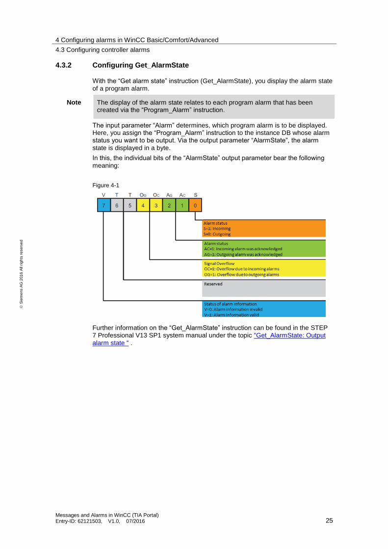
4.3.2 Configuring Get_AlarmState
With the “Get alarm state” instruction (Get_AlarmState), you display the alarm state of a program alarm.
Note The display of the alarm state relates to each program alarm that has been created via the “Program_Alarm” instruction.
The input parameter “Alarm” determines, which program alarm is to be displayed. Here, you assign the “Program_Alarm” instruction to the instance DB whose alarm status you want to be output. Via the output parameter “AlarmState”, the alarm state is displayed in a byte.
In this, the individual bits of the “AlarmState” output parameter bear the following meaning:
Figure 4-1
Further information on the “Get_AlarmState” instruction can be found in the STEP 7 Professional V13 SP1 system manual under the topic “Get_AlarmState: Output alarm state “ .
4 Configuring alarms in WinCC Basic/Comfort/Advanced
4.3 Configuring controller alarms
Messages and Alarms in WinCC (TIA Portal) Entry-ID: 62121503, V1.0, 07/2016 26
S
iem
en
s A
G 2
01
6 A
ll ri
gh
ts r
ese
rve
d
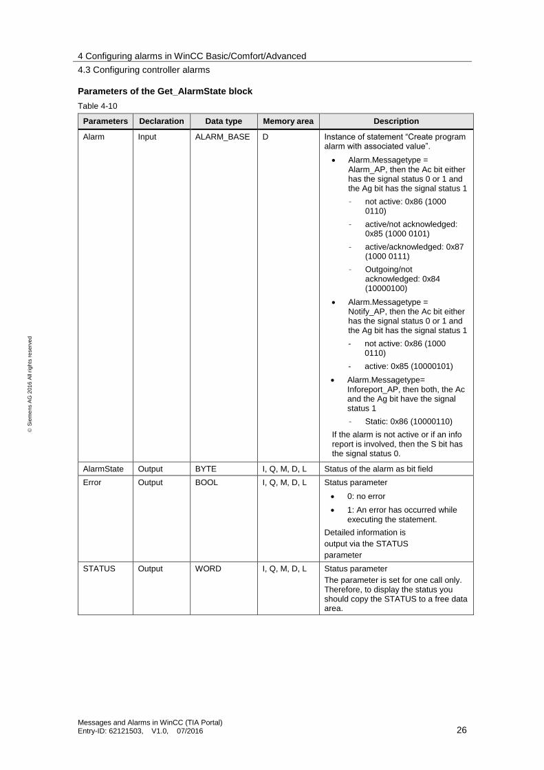
Parameters of the Get_AlarmState block
Table 4-10
Parameters Declaration Data type Memory area Description
Alarm Input ALARM_BASE D Instance of statement “Create program alarm with associated value”.
Alarm.Messagetype = Alarm_AP, then the Ac bit either has the signal status 0 or 1 and the Ag bit has the signal status 1
– not active: 0x86 (1000 0110)
– active/not acknowledged: 0x85 (1000 0101)
– active/acknowledged: 0x87 (1000 0111)
– Outgoing/not acknowledged: 0x84 (10000100)
Alarm.Messagetype = Notify_AP, then the Ac bit either has the signal status 0 or 1 and the Ag bit has the signal status 1
- not active: 0x86 (1000 0110)
- active: 0x85 (10000101)
Alarm.Messagetype= Inforeport_AP, then both, the Ac and the Ag bit have the signal status 1
– Static: 0x86 (10000110)
If the alarm is not active or if an info report is involved, then the S bit has the signal status 0.
AlarmState Output BYTE I, Q, M, D, L Status of the alarm as bit field
Error Output BOOL I, Q, M, D, L Status parameter
0: no error
1: An error has occurred while executing the statement.
Detailed information is
output via the STATUS
parameter
STATUS Output WORD I, Q, M, D, L Status parameter
The parameter is set for one call only. Therefore, to display the status you should copy the STATUS to a free data area.
4 Configuring alarms in WinCC Basic/Comfort/Advanced
4.3 Configuring controller alarms
Messages and Alarms in WinCC (TIA Portal) Entry-ID: 62121503, V1.0, 07/2016 27
S
iem
en
s A
G 2
01
6 A
ll ri
gh
ts r
ese
rve
d
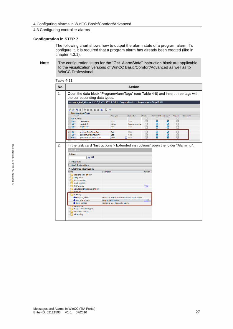
Configuration in STEP 7
The following chart shows how to output the alarm state of a program alarm. To configure it, it is required that a program alarm has already been created (like in chapter 4.3.1).
Note The configuration steps for the “Get_AlarmState” instruction block are applicable to the visualization versions of WinCC Basic/Comfort/Advanced as well as to WinCC Professional.
Table 4-11
No. Action
1. Open the data block “ProgramAlarmTags” (see Table 4-8) and insert three tags with the corresponding data types.
2. In the task card “Instructions > Extended instructions” open the folder “Alarming”.

4 Configuring alarms in WinCC Basic/Comfort/Advanced
4.3 Configuring controller alarms
Messages and Alarms in WinCC (TIA Portal) Entry-ID: 62121503, V1.0, 07/2016 28
S
iem
en
s A
G 2
01
6 A
ll ri
gh
ts r
ese
rve
d
No. Action
3. Per drag&drop, drag the “Get_AlarmState“ block into an empty network of the function block in which the block for the program alarm (Program_Alarm) is called.
4. Connect the “Alarm” input parameter with the instance of the “Program_Alarm” instruction. Then, interconnect the block’s output parameters with the three created tags of the data block.
5. Load the configuration into your CPU.
6. If in the project, the “Program_Alarm” instruction now gets the signal status “true” at the SIG input parameter, the program alarm is output. At the “AlarmState” output of the “Get_AlarmState” instruction, the alarm is then displayed according to the alarm class.

4 Configuring alarms in WinCC Basic/Comfort/Advanced
4.3 Configuring controller alarms
Messages and Alarms in WinCC (TIA Portal) Entry-ID: 62121503, V1.0, 07/2016 29
S
iem
en
s A
G 2
01
6 A
ll ri
gh
ts r
ese
rve
d
4.3.3 Configuring Gen_UsrMsg
With the “Gen_UsrMsg” instruction, you create an alarm that is entered into the diagnostics buffer. Via the Mode parameter, you can choose whether an incoming or an outgoing alarm shall be generated:
Mode = 1: Creating an incoming alarm
Mode = 2: Creating an outgoing alarm
The content of the alarm is defined via text lists and the corresponding text list entries. Via the TextListID and TextID parameters, you can select the appropriate entry that you want to write into the diagnostics buffer. In the text lists, you can also define associated values that are to be additionally displayed in the diagnostics buffer.
Further information on the “Gen_UsrMsg” instruction can be found in the STEP 7 Professional V13 SP1 system manual under the topic “Gen_UsrMsg: Generate user diagnostics alarms“
Note The statement “Generate user diagnostics alarm”(GEN_UsrMsg) is only available from STEP 7 V13 SP1 and higher.
Parameters of the Get_AlarmState block
Table 4-12
Parameters Declaration Data type Memory area Description
Mode Input UInt E, A, M, D, L, or constant
Parameter for the selection of the alarm status
1: incoming alarm
2: outgoing alarm
TextID Input UInt E, A, M, D, L, or constant
ID of text list entry that is to be used for the alarm text.
TextListID Input UInt E, A, M, D, L, or constant
ID of text list that contains text list entries.
Ret_Val Return_ Int I, Q, M, D, L Error code of instruction.
AssocValues InOut Variant D, L Pointer on the AssocValues system data type, via which you define the associated values.
Configuration in STEP 7
Note The configuration steps for the “Get_AlarmState” instruction block are applicable to the visualization versions of WinCC Basic/Comfort/Advanced as well as to WinCC Professional.
4 Configuring alarms in WinCC Basic/Comfort/Advanced
4.3 Configuring controller alarms
Messages and Alarms in WinCC (TIA Portal) Entry-ID: 62121503, V1.0, 07/2016 30
S
iem
en
s A
G 2
01
6 A
ll ri
gh
ts r
ese
rve
d
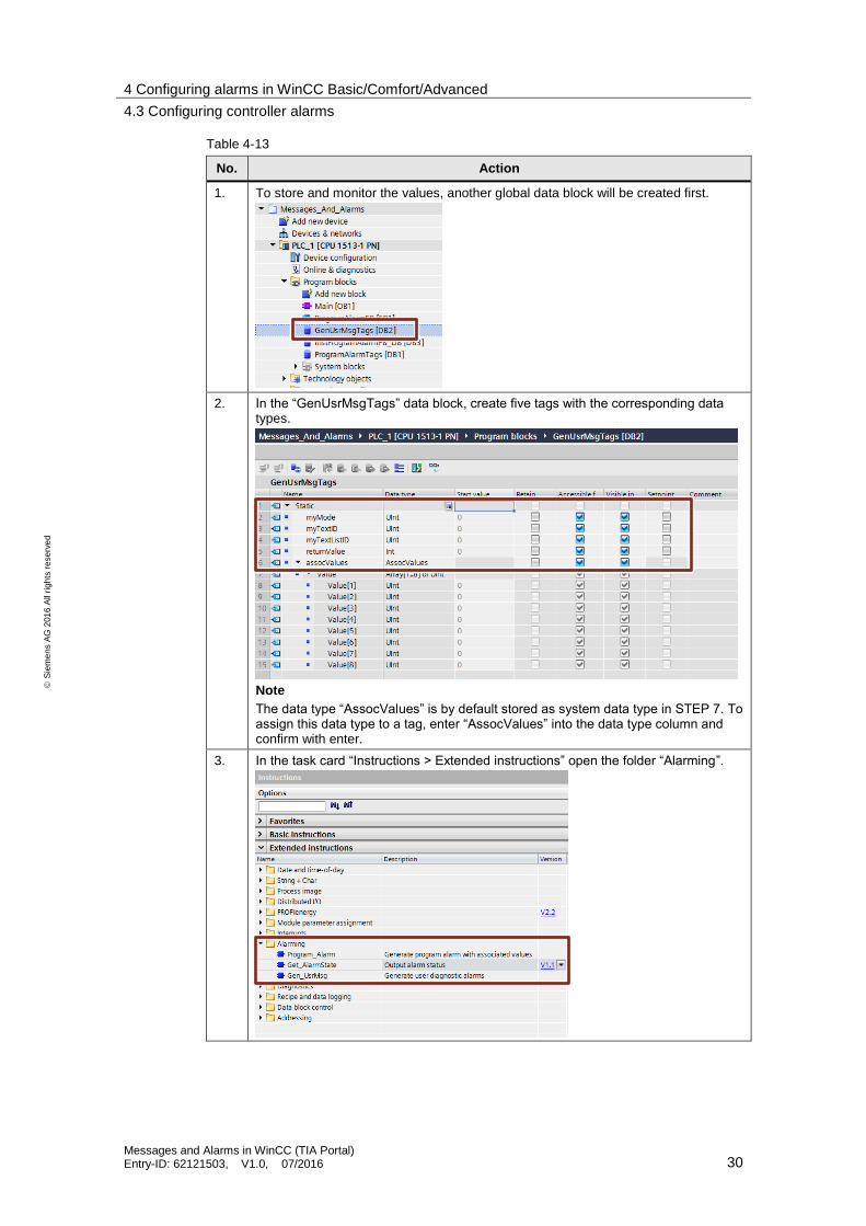
Table 4-13
No. Action
1. To store and monitor the values, another global data block will be created first.
2. In the “GenUsrMsgTags” data block, create five tags with the corresponding data types.
Note
The data type “AssocValues” is by default stored as system data type in STEP 7. To assign this data type to a tag, enter “AssocValues” into the data type column and confirm with enter.
3. In the task card “Instructions > Extended instructions” open the folder “Alarming”.

4 Configuring alarms in WinCC Basic/Comfort/Advanced
4.3 Configuring controller alarms
Messages and Alarms in WinCC (TIA Portal) Entry-ID: 62121503, V1.0, 07/2016 31
S
iem
en
s A
G 2
01
6 A
ll ri
gh
ts r
ese
rve
d
No. Action
4. Per drag&drop, drag the “Gen_UsrMsg“ block into an empty network of the function block in which the block for the program alarm is called.
5. Connect the “Alarm” input parameter with the instance of the “Program_Alarm” instruction. Then, interconnect the block’s output parameters with the three created tags of the data block.
4 Configuring alarms in WinCC Basic/Comfort/Advanced
4.3 Configuring controller alarms
Messages and Alarms in WinCC (TIA Portal) Entry-ID: 62121503, V1.0, 07/2016 32
S
iem
en
s A
G 2
01
6 A
ll ri
gh
ts r
ese
rve
d
No. Action
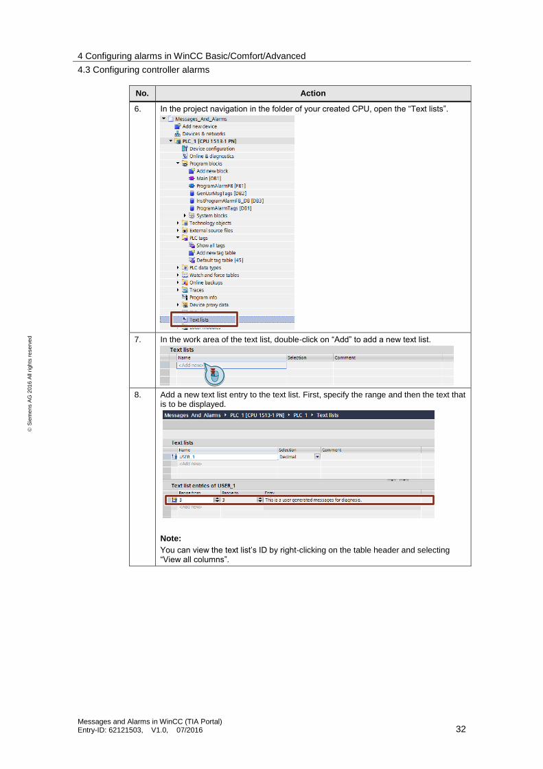
6. In the project navigation in the folder of your created CPU, open the “Text lists”.
7. In the work area of the text list, double-click on “Add” to add a new text list.
8. Add a new text list entry to the text list. First, specify the range and then the text that is to be displayed.
Note:
You can view the text list’s ID by right-clicking on the table header and selecting “View all columns”.
4 Configuring alarms in WinCC Basic/Comfort/Advanced
4.4 Using alarm classes
Messages and Alarms in WinCC (TIA Portal) Entry-ID: 62121503, V1.0, 07/2016 33
S
iem
en
s A
G 2
01
6 A
ll ri
gh
ts r
ese
rve
d
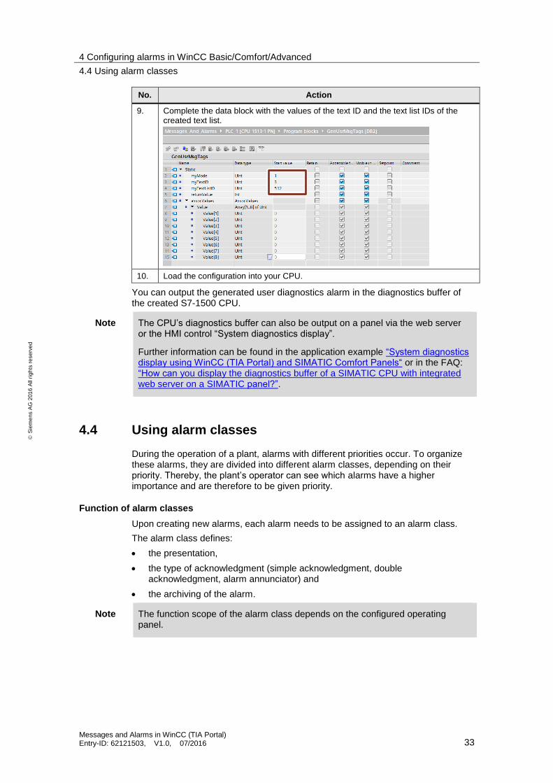
No. Action
9. Complete the data block with the values of the text ID and the text list IDs of the created text list.
10. Load the configuration into your CPU.
You can output the generated user diagnostics alarm in the diagnostics buffer of the created S7-1500 CPU.
Note The CPU’s diagnostics buffer can also be output on a panel via the web server or the HMI control “System diagnostics display”.
Further information can be found in the application example “System diagnostics display using WinCC (TIA Portal) and SIMATIC Comfort Panels“ or in the FAQ: “How can you display the diagnostics buffer of a SIMATIC CPU with integrated web server on a SIMATIC panel?”.
4.4 Using alarm classes
During the operation of a plant, alarms with different priorities occur. To organize these alarms, they are divided into different alarm classes, depending on their priority. Thereby, the plant’s operator can see which alarms have a higher importance and are therefore to be given priority.
Function of alarm classes
Upon creating new alarms, each alarm needs to be assigned to an alarm class.
The alarm class defines:
the presentation,
the type of acknowledgment (simple acknowledgment, double acknowledgment, alarm annunciator) and
the archiving of the alarm.
Note The function scope of the alarm class depends on the configured operating panel.
4 Configuring alarms in WinCC Basic/Comfort/Advanced
4.5 Using alarm groups
Messages and Alarms in WinCC (TIA Portal) Entry-ID: 62121503, V1.0, 07/2016 34
S
iem
en
s A
G 2
01
6 A
ll ri
gh
ts r
ese
rve
d
Types of alarm classes
The following types of alarm classes are available in WinCC (TIA Portal).
Predefined alarm classes
For every operating panel, you can find predefined alarm classes in the project tree under “HMI alarms” in the “Alarm class” tab. These alarm classes cannot be erased and can only be edited to a limited extent.
Unser-defined alarm classes
For every operating panel, further alarm classes can be created in the project tree under “HMI alarms” in the “Alarm class” tab. In these alarm classes, the presentation and the type of acknowledgment of the corresponding alarms can be configured individually.
Project-wide alarm classes (not with Basic Panels)
Project-wide alarm classes can be used across any operating panel in the project. In the project tree under “Common data > “Alarm classes”, the alarm classes are displayed and new project-wide alarm classes are configured.
4.5 Using alarm groups
During a plant’s operation, different alarms regarding various procedures and areas occur. To arrange these alarms (for example, by a certain plant section) for greater transparency, alarms can be added to alarm groups.
Function scope of alarm groups in WinCC Basic/Comfort/Advanced
In WinCC Basic/Comfort/Advanced, plant sections can be viewed separately with the help of alarm groups and corresponding alarms can be acknowledged collectively, if needed. Only acknowledgment-dependent alarms can be assigned to an alarm group, regardless of the alarm class used.
Example If several acknowledgment-dependent alarms are assigned to an alarm group, all alarms of the alarm group are acknowledged collectively if only one of them is acknowledged.
Intended use
Using alarm groups is recommended for the following alarms:
Error alarms with the same cause.
Similar alarms.
Alarms from a plant section (e.g. Squeezer_1).
Alarms that are part of a process (e.g. Temperature monitoring).
4 Configuring alarms in WinCC Basic/Comfort/Advanced
4.6 The acknowledgment types
Messages and Alarms in WinCC (TIA Portal) Entry-ID: 62121503, V1.0, 07/2016 35
S
iem
en
s A
G 2
01
6 A
ll ri
gh
ts r
ese
rve
d
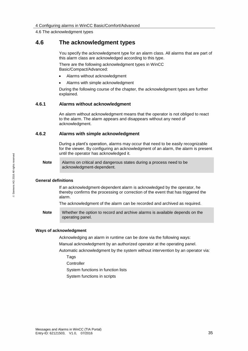
4.6 The acknowledgment types
You specify the acknowledgment type for an alarm class. All alarms that are part of this alarm class are acknowledged according to this type.
There are the following acknowledgment types in WinCC Basic/Compact/Advanced:
Alarms without acknowledgment
Alarms with simple acknowledgment
During the following course of the chapter, the acknowledgment types are further explained.
4.6.1 Alarms without acknowledgment
An alarm without acknowledgment means that the operator is not obliged to react to the alarm. The alarm appears and disappears without any need of acknowledgment.
4.6.2 Alarms with simple acknowledgment
During a plant’s operation, alarms may occur that need to be easily recognizable for the viewer. By configuring an acknowledgment of an alarm, the alarm is present until the operator has acknowledged it.
Note Alarms on critical and dangerous states during a process need to be acknowledgment-dependent.
General definitions
If an acknowledgment-dependent alarm is acknowledged by the operator, he thereby confirms the processing or correction of the event that has triggered the alarm.
The acknowledgment of the alarm can be recorded and archived as required.
Note Whether the option to record and archive alarms is available depends on the operating panel.
Ways of acknowledgment
Acknowledging an alarm in runtime can be done via the following ways:
Manual acknowledgment by an authorized operator at the operating panel.
Automatic acknowledgment by the system without intervention by an operator via:
Tags
Controller
System functions in function lists
System functions in scripts

4 Configuring alarms in WinCC Basic/Comfort/Advanced
4.6 The acknowledgment types
Messages and Alarms in WinCC (TIA Portal) Entry-ID: 62121503, V1.0, 07/2016 36
S
iem
en
s A
G 2
01
6 A
ll ri
gh
ts r
ese
rve
d
Acknowledgment by an operator at the operating panel
Depending on the configuration, the operator can acknowledge an alarm in runtime in the following ways:
Via the “Acknowledge” button in an alarm view
Note The button first needs to be activated under Alarm view properties -> Toolbar -> Buttons.
Via function buttons and configured buttons with the configured function “MessageDisplayAcknowledgeMessage” in screens
Via the acknowledge button <ACK> on an operating panel with pushbutton panel.
Note Critical alarms should only be acknowledged by authorized operators. Therefore, you should equip all operating and display elements for acknowledging alarms with operating authorizations.
Acknowledgment by controller
Other than acknowledging an alarm on the operating panel, the acknowledgment can also be done via the controller program. In that case, the acknowledgment is done via the PLC acknowledgment tag which can be configured on every acknowledgment-dependent alarm. Further information on how to configure the acknowledgement tag can be found in the chapter “Configuring bit alarms”.
Acknowledging multiple alarms collectively
To acknowledge multiple alarms collectively, those alarms need to be assigned to the same alarm group. If an alarm from this alarm group is then acknowledged, all other alarms from this alarm group are acknowledged as well. As a result, it is no longer necessary to acknowledge each alarm separately.
Further information on alarm groups can be found in the chapter “Using alarm groups”.
The alarm is triggered via an event.
The operator recognizes the alarm as acknowledgment-dependent and acknowledges the alarm.
The alarm is displayed in an alarm view/ an alarm window with the status “incoming”.
The operator fixes the cause that has triggered the event.
The alarm’s status switches to “incoming” + “acknowledged”.
The alarm’s status switches to “outgoing” + “acknowledged”.
5 Configuring alarms in WinCC Professional
5.1 Configuring user-defined alarms
Messages and Alarms in WinCC (TIA Portal) Entry-ID: 62121503, V1.0, 07/2016 37
S
iem
en
s A
G 2
01
6 A
ll ri
gh
ts r
ese
rve
d
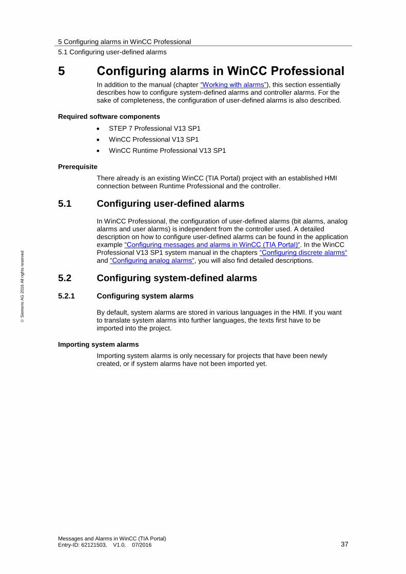
5 Configuring alarms in WinCC Professional In addition to the manual (chapter “Working with alarms”), this section essentially describes how to configure system-defined alarms and controller alarms. For the sake of completeness, the configuration of user-defined alarms is also described.
Required software components
STEP 7 Professional V13 SP1
WinCC Professional V13 SP1
WinCC Runtime Professional V13 SP1
Prerequisite
There already is an existing WinCC (TIA Portal) project with an established HMI connection between Runtime Professional and the controller.
5.1 Configuring user-defined alarms
In WinCC Professional, the configuration of user-defined alarms (bit alarms, analog alarms and user alarms) is independent from the controller used. A detailed description on how to configure user-defined alarms can be found in the application example “Configuring messages and alarms in WinCC (TIA Portal)“. In the WinCC Professional V13 SP1 system manual in the chapters “Configuring discrete alarms“ and “Configuring analog alarms“, you will also find detailed descriptions.
5.2 Configuring system-defined alarms
5.2.1 Configuring system alarms
By default, system alarms are stored in various languages in the HMI. If you want to translate system alarms into further languages, the texts first have to be imported into the project.
Importing system alarms
Importing system alarms is only necessary for projects that have been newly created, or if system alarms have not been imported yet.
5 Configuring alarms in WinCC Professional
5.2 Configuring system-defined alarms
Messages and Alarms in WinCC (TIA Portal) Entry-ID: 62121503, V1.0, 07/2016 38
S
iem
en
s A
G 2
01
6 A
ll ri
gh
ts r
ese
rve
d
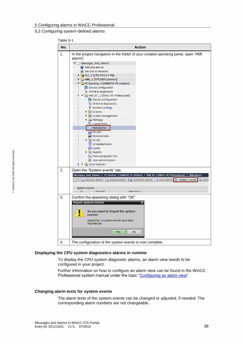
Table 5-1
No. Action
1. In the project navigation in the folder of your created operating panel, open “HMI alarms”.
2. Open the “System events” tab.
3. Confirm the appearing dialog with “OK”.
4. The configuration of the system events is now complete.
Displaying the CPU system diagnostics alarms in runtime
To display the CPU system diagnostic alarms, an alarm view needs to be configured in your project.
Further information on how to configure an alarm view can be found in the WinCC Professional system manual under the topic “Configuring an alarm view“
Changing alarm texts for system events
The alarm texts of the system events can be changed or adjusted, if needed. The corresponding alarm numbers are not changeable.
5 Configuring alarms in WinCC Professional
5.2 Configuring system-defined alarms
Messages and Alarms in WinCC (TIA Portal) Entry-ID: 62121503, V1.0, 07/2016 39
S
iem
en
s A
G 2
01
6 A
ll ri
gh
ts r
ese
rve
d
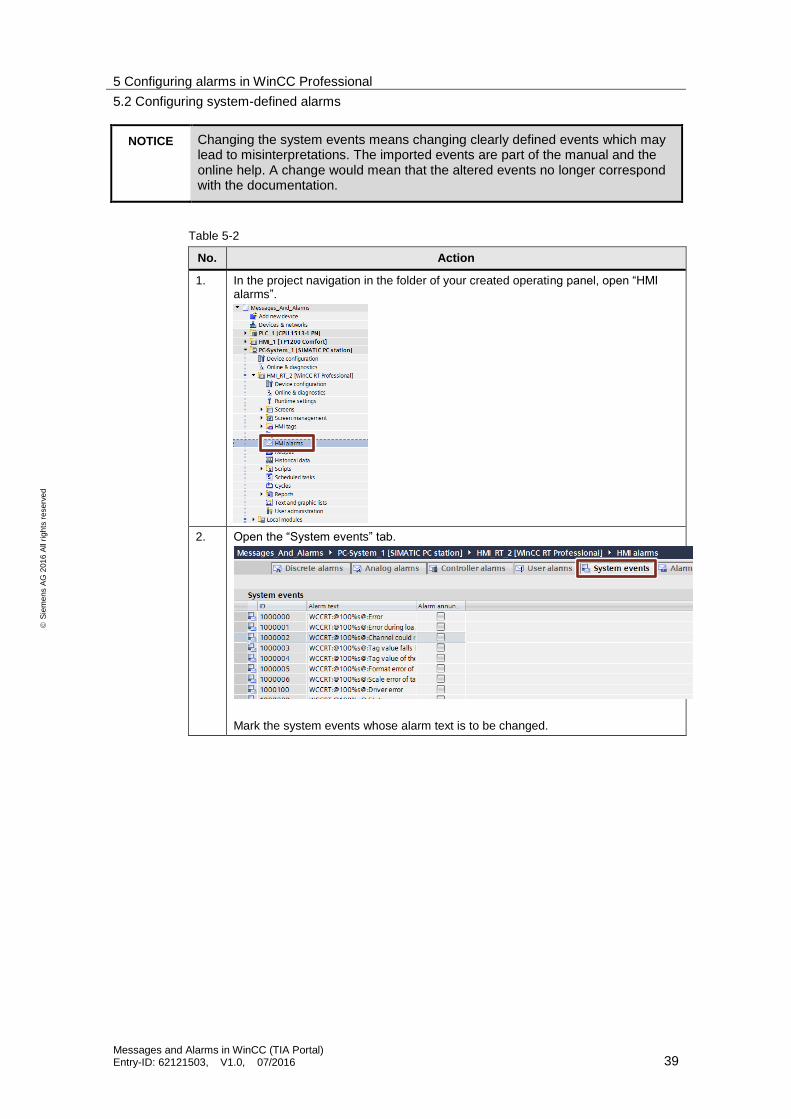
NOTICE Changing the system events means changing clearly defined events which may lead to misinterpretations. The imported events are part of the manual and the online help. A change would mean that the altered events no longer correspond with the documentation.
Table 5-2
No. Action
1. In the project navigation in the folder of your created operating panel, open “HMI alarms”.
2. Open the “System events” tab.
Mark the system events whose alarm text is to be changed.
5 Configuring alarms in WinCC Professional
5.2 Configuring system-defined alarms
Messages and Alarms in WinCC (TIA Portal) Entry-ID: 62121503, V1.0, 07/2016 40
S
iem
en
s A
G 2
01
6 A
ll ri
gh
ts r
ese
rve
d
No. Action
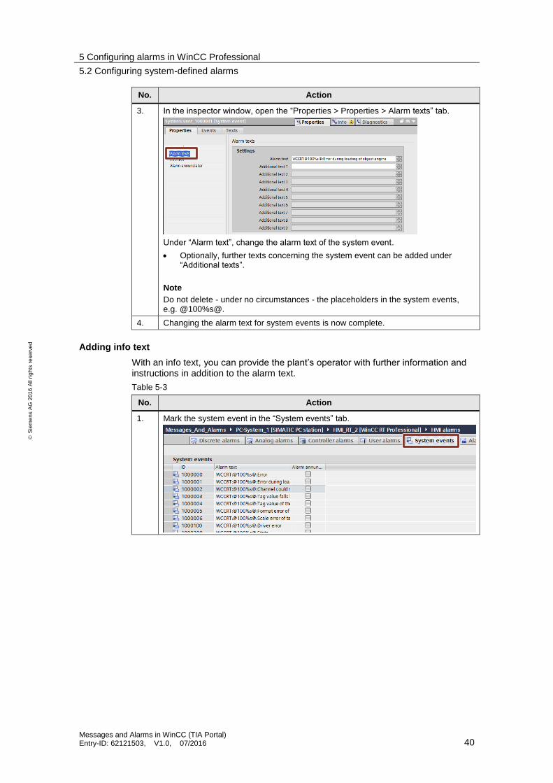
3. In the inspector window, open the “Properties > Properties > Alarm texts” tab.
Under “Alarm text”, change the alarm text of the system event.
Optionally, further texts concerning the system event can be added under “Additional texts”.
Note
Do not delete - under no circumstances - the placeholders in the system events, e.g. @100%s@.
4. Changing the alarm text for system events is now complete.
Adding info text
With an info text, you can provide the plant’s operator with further information and instructions in addition to the alarm text.
Table 5-3
No. Action
1. Mark the system event in the “System events” tab.
5 Configuring alarms in WinCC Professional
5.2 Configuring system-defined alarms
Messages and Alarms in WinCC (TIA Portal) Entry-ID: 62121503, V1.0, 07/2016 41
S
iem
en
s A
G 2
01
6 A
ll ri
gh
ts r
ese
rve
d
No. Action
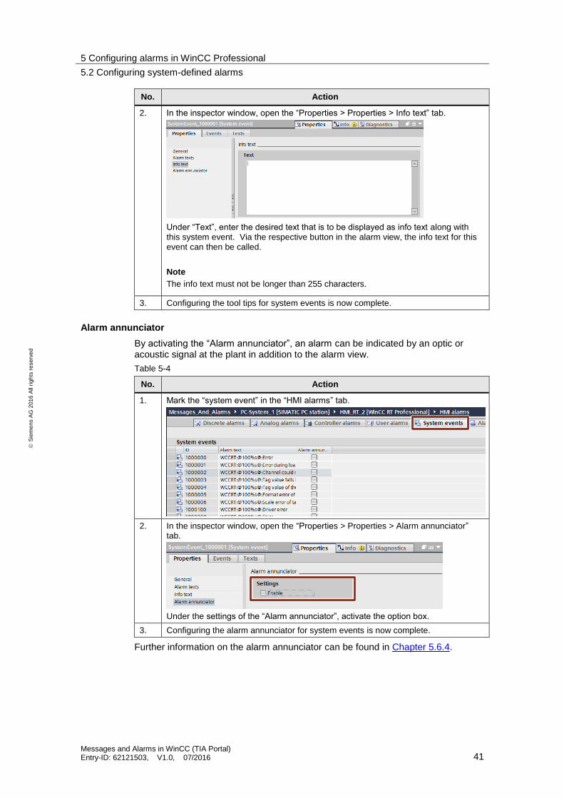
2. In the inspector window, open the “Properties > Properties > Info text” tab.
Under “Text”, enter the desired text that is to be displayed as info text along with this system event. Via the respective button in the alarm view, the info text for this event can then be called.
Note
The info text must not be longer than 255 characters.
3. Configuring the tool tips for system events is now complete.
Alarm annunciator
By activating the “Alarm annunciator”, an alarm can be indicated by an optic or acoustic signal at the plant in addition to the alarm view.
Table 5-4
No. Action
1. Mark the “system event” in the “HMI alarms” tab.
2. In the inspector window, open the “Properties > Properties > Alarm annunciator” tab.
Under the settings of the “Alarm annunciator”, activate the option box.
3. Configuring the alarm annunciator for system events is now complete.
Further information on the alarm annunciator can be found in Chapter 5.6.4.

5 Configuring alarms in WinCC Professional
5.2 Configuring system-defined alarms
Messages and Alarms in WinCC (TIA Portal) Entry-ID: 62121503, V1.0, 07/2016 42
S
iem
en
s A
G 2
01
6 A
ll ri
gh
ts r
ese
rve
d
5.2.2 Configuring CPU system diagnostics alarms
The following section describes how to configure the display of system diagnostics alarms of a CPU on an operating panel, using the following components:
CPU 1513-1PN
WinCC Runtime Professional
Settings in STEP 7 Professional
Table 5-5
No. Action
1. Open the “Device configuration” of your CPU in the project navigation.
2. In the device view, mark the CPU on the module rack.
3. In the inspector window, open the “Properties > General > System diagnostics” tab.
The option box “Activate system diagnostics for this device” is by default activated and cannot be deactivated.
Optional:
In the lower area of the inspector window under “Alarm settings” you may adjust the alarms and alarm classes of each category according to your needs.

5 Configuring alarms in WinCC Professional
5.3 Configuring controller alarms
Messages and Alarms in WinCC (TIA Portal) Entry-ID: 62121503, V1.0, 07/2016 43
S
iem
en
s A
G 2
01
6 A
ll ri
gh
ts r
ese
rve
d
No. Action
4. Right-click on CPU in the project navigation. In the context menu, select “Compile > Hardware (rebuild all)”.
5. The settings in STEP 7 Professional are now complete.
Displaying the CPU system diagnostics alarms in runtime
To display the CPU system diagnostic alarms, an alarm view needs to be configured in your project.
Further information on how to configure an alarm view can be found in the WinCC Professional system manual under the topic “Configuring an alarm view“
5.3 Configuring controller alarms
5.3.1 Configuring Program_Alarm
The statement “Program_Alarm: “Generate program alarms with associated values” monitors a signal and generates an incoming program alarm upon a signal change from 0 to 1 at the SIG parameter.
More detailed Information on the alarm block’s functions and individual parameters have already been described in Chapter 4.3.1 of this document.
Settings in STEP7
The necessary configuration steps which are required for the “Program_Alarm” alarm block in STEP 7 can be found in Chapter 4.3.1 of this document.
5 Configuring alarms in WinCC Professional
5.3 Configuring controller alarms
Messages and Alarms in WinCC (TIA Portal) Entry-ID: 62121503, V1.0, 07/2016 44
S
iem
en
s A
G 2
01
6 A
ll ri
gh
ts r
ese
rve
d
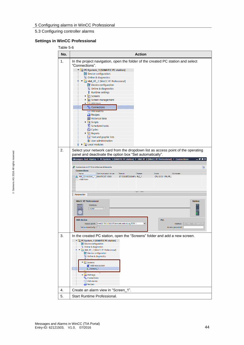
Settings in WinCC Professional
Table 5-6
No. Action
1. In the project navigation, open the folder of the created PC station and select “Connections”.
2. Select your network card from the dropdown list as access point of the operating panel and deactivate the option box “Set automatically”.
3. In the created PC station, open the “Screens” folder and add a new screen.
4. Create an alarm view in “Screen_1”.
5. Start Runtime Professional.
5 Configuring alarms in WinCC Professional
5.4 Using alarm classes in WinCC Professional
Messages and Alarms in WinCC (TIA Portal) Entry-ID: 62121503, V1.0, 07/2016 45
S
iem
en
s A
G 2
01
6 A
ll ri
gh
ts r
ese
rve
d
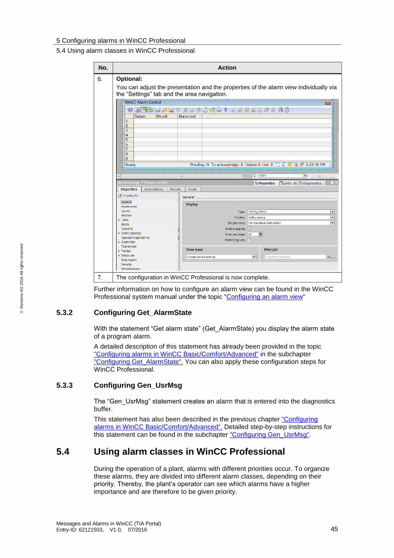
No. Action
6. Optional:
You can adjust the presentation and the properties of the alarm view individually via the “Settings” tab and the area navigation.
7. The configuration in WinCC Professional is now complete.
Further information on how to configure an alarm view can be found in the WinCC Professional system manual under the topic “Configuring an alarm view“
5.3.2 Configuring Get_AlarmState
With the statement “Get alarm state” (Get_AlarmState) you display the alarm state of a program alarm.
A detailed description of this statement has already been provided in the topic “Configuring alarms in WinCC Basic/Comfort/Advanced“ in the subchapter “Configuring Get_AlarmState“. You can also apply these configuration steps for WinCC Professional.
5.3.3 Configuring Gen_UsrMsg
The “Gen_UsrMsg” statement creates an alarm that is entered into the diagnostics buffer.
This statement has also been described in the previous chapter “Configuring alarms in WinCC Basic/Comfort/Advanced“. Detailed step-by-step instructions for this statement can be found in the subchapter “Configuring Gen_UsrMsg“.
5.4 Using alarm classes in WinCC Professional
During the operation of a plant, alarms with different priorities occur. To organize these alarms, they are divided into different alarm classes, depending on their priority. Thereby, the plant’s operator can see which alarms have a higher importance and are therefore to be given priority.
5 Configuring alarms in WinCC Professional
5.4 Using alarm classes in WinCC Professional
Messages and Alarms in WinCC (TIA Portal) Entry-ID: 62121503, V1.0, 07/2016 46
S
iem
en
s A
G 2
01
6 A
ll ri
gh
ts r
ese
rve
d
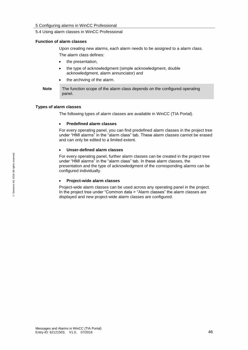
Function of alarm classes
Upon creating new alarms, each alarm needs to be assigned to a alarm class.
The alarm class defines:
the presentation,
the type of acknowledgment (simple acknowledgment, double acknowledgment, alarm annunciator) and
the archiving of the alarm.
Note The function scope of the alarm class depends on the configured operating panel.
Types of alarm classes
The following types of alarm classes are available in WinCC (TIA Portal).
Predefined alarm classes
For every operating panel, you can find predefined alarm classes in the project tree under “HMI alarms” in the “alarm class” tab. These alarm classes cannot be erased and can only be edited to a limited extent.
Unser-defined alarm classes
For every operating panel, further alarm classes can be created in the project tree under “HMI alarms” in the “alarm class” tab. In these alarm classes, the presentation and the type of acknowledgment of the corresponding alarms can be configured individually.
Project-wide alarm classes
Project-wide alarm classes can be used across any operating panel in the project. In the project tree under “Common data > “Alarm classes” the alarm classes are displayed and new project-wide alarm classes are configured.
5 Configuring alarms in WinCC Professional
5.5 Using alarm groups in WinCC Professional
Messages and Alarms in WinCC (TIA Portal) Entry-ID: 62121503, V1.0, 07/2016 47
S
iem
en
s A
G 2
01
6 A
ll ri
gh
ts r
ese
rve
d
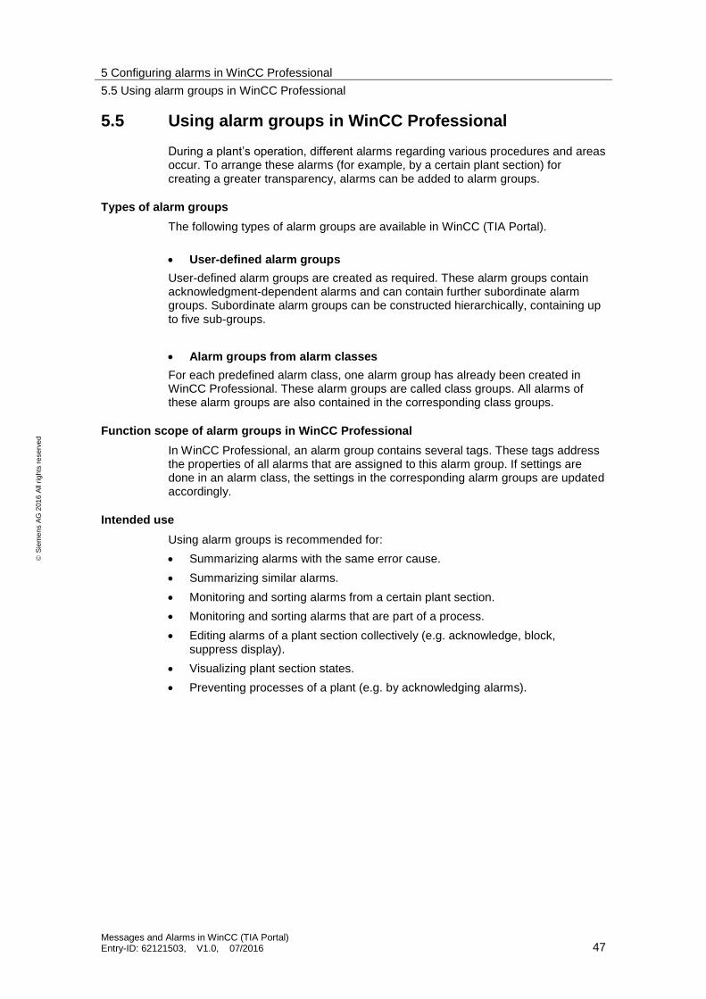
5.5 Using alarm groups in WinCC Professional
During a plant’s operation, different alarms regarding various procedures and areas occur. To arrange these alarms (for example, by a certain plant section) for creating a greater transparency, alarms can be added to alarm groups.
Types of alarm groups
The following types of alarm groups are available in WinCC (TIA Portal).
User-defined alarm groups
User-defined alarm groups are created as required. These alarm groups contain acknowledgment-dependent alarms and can contain further subordinate alarm groups. Subordinate alarm groups can be constructed hierarchically, containing up to five sub-groups.
Alarm groups from alarm classes
For each predefined alarm class, one alarm group has already been created in WinCC Professional. These alarm groups are called class groups. All alarms of these alarm groups are also contained in the corresponding class groups.
Function scope of alarm groups in WinCC Professional
In WinCC Professional, an alarm group contains several tags. These tags address the properties of all alarms that are assigned to this alarm group. If settings are done in an alarm class, the settings in the corresponding alarm groups are updated accordingly.
Intended use
Using alarm groups is recommended for:
Summarizing alarms with the same error cause.
Summarizing similar alarms.
Monitoring and sorting alarms from a certain plant section.
Monitoring and sorting alarms that are part of a process.
Editing alarms of a plant section collectively (e.g. acknowledge, block, suppress display).
Visualizing plant section states.
Preventing processes of a plant (e.g. by acknowledging alarms).
5 Configuring alarms in WinCC Professional
5.6 The acknowledgment types in WinCC Professional
Messages and Alarms in WinCC (TIA Portal) Entry-ID: 62121503, V1.0, 07/2016 48
S
iem
en
s A
G 2
01
6 A
ll ri
gh
ts r
ese
rve
d
5.6 The acknowledgment types in WinCC Professional
You specify the acknowledgment type for an alarm class. All alarms that are part of this alarm class are acknowledged according to this type.
In WinCC Professional, there are the following types of acknowledgment which are divided into further sub-types:
Alarms without acknowledgment
Alarms with simple acknowledgment
Alarms with double acknowledgment
During the following course of the chapter, these acknowledgment types are further explained.
5.6.1 Alarm without acknowledgment
An alarm without acknowledgment means that the operator is not obliged to react to the alarm. The alarm appears and disappears without any need of acknowledgment.
Alarm without “outgoing” status and without acknowledgment
So long as the event that has triggered the alarm is present, the alarm is present. If the event that has triggered the alarm is gone, the alarm is no longer displayed. The alarm is archived and must not be acknowledged.
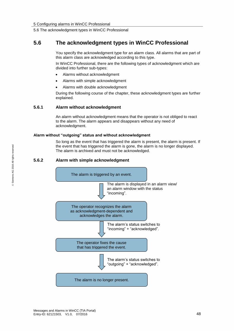
5.6.2 Alarm with simple acknowledgment
The alarm is triggered by an event.
The operator recognizes the alarm as acknowledgment-dependent and
acknowledges the alarm.
The alarm is displayed in an alarm view/ an alarm window with the status “incoming”.
The alarm’s status switches to “incoming” + “acknowledged”.
The alarm’s status switches to “outgoing” + “acknowledged”.
The operator fixes the cause that has triggered the event.
The alarm is no longer present.

5 Configuring alarms in WinCC Professional
5.6 The acknowledgment types in WinCC Professional
Messages and Alarms in WinCC (TIA Portal) Entry-ID: 62121503, V1.0, 07/2016 49
S
iem
en
s A
G 2
01
6 A
ll ri
gh
ts r
ese
rve
d
An alarm with a simple acknowledgment requires an acknowledgment as soon as the event that has triggered the alarm occurred. The alarm is present until the operator has acknowledged the alarm.
Alarm without “outgoing” status and with acknowledgment
The alarm is present as long as the event that has triggered the alarm is present and the alarm has not been acknowledged. If the event that has triggered the alarm is gone and the alarm has been acknowledged, the alarm is no longer displayed. The alarm is archived.
First-in alarm with flash signal and simple acknowledgment
A first-in alarm is an alarm within an alarm class. The alarm whose status changes first after the last acknowledgment is highlighted by flashing in the alarm window. The alarm is then designated as first in alarm.
New value alarm with flash signal and simple acknowledgment
New value alarms are alarms within an alarm class. The alarms whose status changed after the last acknowledgment are highlighted by flashing in the alarm window.
5 Configuring alarms in WinCC Professional
5.6 The acknowledgment types in WinCC Professional
Messages and Alarms in WinCC (TIA Portal) Entry-ID: 62121503, V1.0, 07/2016 50
S
iem
en
s A
G 2
01
6 A
ll ri
gh
ts r
ese
rve
d
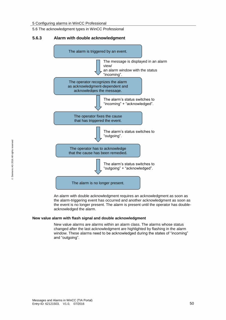
5.6.3 Alarm with double acknowledgment
An alarm with double acknowledgment requires an acknowledgment as soon as the alarm-triggering event has occurred and another acknowledgment as soon as the event is no longer present. The alarm is present until the operator has double-acknowledged the alarm.
New value alarm with flash signal and double acknowledgment
New value alarms are alarms within an alarm class. The alarms whose status changed after the last acknowledgment are highlighted by flashing in the alarm window. These alarms need to be acknowledged during the states of “incoming” and “outgoing”.
The alarm is triggered by an event.
The operator recognizes the alarm as acknowledgment-dependent and
acknowledges the message.
The message is displayed in an alarm view/ an alarm window with the status “incoming”.
The alarm’s status switches to “incoming” + “acknowledged”.
The operator fixes the cause that has triggered the event.
The alarm is no longer present.
The alarm’s status switches to “outgoing” + “acknowledged”.
The operator has to acknowledge that the cause has been remedied.
The alarm’s status switches to “outgoing”.
5 Configuring alarms in WinCC Professional
5.6 The acknowledgment types in WinCC Professional
Messages and Alarms in WinCC (TIA Portal) Entry-ID: 62121503, V1.0, 07/2016 51
S
iem
en
s A
G 2
01
6 A
ll ri
gh
ts r
ese
rve
d
5.6.4 General information on acknowledgment types
Acknowledging multiple alarms collectively
In WinCC Professional, acknowledging multiple alarms collectively can be done via a collective acknowledgment or via an alarm group.
Collective acknowledgment via the alarm view Via the “Acknowledge collectively” button of an alarm view, all visible, pending and acknowledgment-dependent alarms can be acknowledged at once.
Note Alarms with single acknowledgment activated cannot be acknowledged via the collective acknowledgment.
Acknowledgment via alarm groups To acknowledge multiple alarms collectively, those alarms need to be assigned to the same alarm group. If an alarm from this alarm group is then acknowledged, all other alarms from this alarm group are acknowledged as well. As a result, it is no longer necessary to acknowledge each alarm separately.
Further information on alarm groups can be found in Chapter 5.5.
Alarm annunciator
If an alarm annunciator has been configured for an acknowledgment-dependent alarm, there are the following possibilities to acknowledge the alarm annunciator:
The operator acknowledges the alarm annunciator together with the acknowledgment-dependent alarm.
The operator acknowledges the alarm annunciator via the “Acknowledge alarm annunciator” button on the alarm view.
The alarm annunciator is acknowledged via a tag.
Settings for the acknowledgment of the alarm annunciator are done in the alarm class settings. Those settings apply separately for each acknowledgment-dependent alarm class.
Emergency acknowledgment
Via the “Emergency acknowledgment” button of an alarm view, acknowledgment-dependent alarms can be acknowledged directly by means of the alarm number during an emergency.
NOTICE The acknowledgment bit will also be transmitted to the controller, if the alarm indicated by the corresponding alarm number is not present.
Use the emergency acknowledgment for emergencies only.
Note Further information on the acknowledgment of alarms in WinCC Professional can be found at the following link:
http://support.automation.siemens.com/WW/view/en/55622122

6 References
Messages and Alarms in WinCC (TIA Portal) Entry-ID: 62121503, V1.0, 07/2016 52
S
iem
en
s A
G 2
01
6 A
ll ri
gh
ts r
ese
rve
d
6 References Table 6-1
Topic
\1\ Siemens Industry Online Support
https://support.industry.siemens.com
\2\ Download page of the entry https://support.industry.siemens.com/cs/ww/en/view/62121503
\3\ STEP 7 Professional V13 SP1 Manual
https://support.industry.siemens.com/cs/ww/en/view/109011420/74495465995
\4\ System manual WinCC Advanced V13.0 SP1
https://support.industry.siemens.com/cs/ww/en/view/109091876/74461101323
\5\ System manual WinCC Professional V13.0 SP1
https://support.industry.siemens.com/cs/ww/en/view/109096785/74713345163
\6\ Application example: Configuring Messages and Alarms in WinCC (TIA Portal)
https://support.industry.siemens.com/cs/ww/en/view/62121503
\7\ Application example: System diagnostics display using WinCC (TIA Portal) and SIMATIC Comfort Panels.
https://support.industry.siemens.com/cs/ww/en/view/61910954
\8\ Application example: System Diagnostics with S7-1500 and TIA Portal
https://support.industry.siemens.com/cs/ww/en/view/68011497
\9\ FAQ: How can a diagnostics buffer of a SIMATIC CPU with integrated web server be displayed on a SIMATIC panel?
https://support.industry.siemens.com/cs/ww/en/view/59601288
\10\ FAQ: How can alarm messages be acknowledged in WinCC Runtime Professional V11 and higher?
https://support.industry.siemens.com/cs/ww/en/view/55622122
7 History
Table 7-1
Version Date Modifications
V1.0 07/2016 First version