Embed Size (px)
Citation preview

Installation instructions available at www.greenheck.com.
AMD-33-TDThermal Dispersion Air Measuring Station
with VCD-33 Control DamperApplication and DesignThe AMD-33-TD combines the functionality of a highly accurate thermal dispersion airflow measuring station and a low leakage control damper into one compact assembly that both measures and regulates airflow volumes to a target set-point. The AMD-33-TD comes standard with Vari-Green thermal dispersion probes factory installed in the damper sleeve, a modulating actuator and a Vari-Green airflow measurement transmitter that outputs a signal proportional to the cfm going through the unit. The transmitter and actuator are factory wired to a terminal block for easy single-point wiring. The optional factory supplied controller makes the AMD-33-TD a turn-key solution for the measurement and control of airflow. Factory supplied controllers configured for analog operation accept a 0-10 VDC setpoint signal proportional to the required cfm and output a 0-10 VDC signal proportional to the real-time cfm going through the unit. Factory supplied controllers can also be ordered with BACnet MS/TP communication capabilities. See the installation and operation manual for a list of the BACnet datapoints.
Ratings Velocity: 100 - 3,000 fpm (0.5 - 15.2 m/s) Leakage: 6 cfm/ft2 @ 4 in. wg (110 cmh/m2 @ 1 kPa) 3 cfm/ft2 @ 1 in. wg (55 cmh/m2 @ 0.25 kPa) Temperature: -20° to 140°F (-29° to 60°C). Consult factory for temperatures lower than -20°F (-29°C). Monitor Accuracy: 2-3% of reading
*W & H dimension furnished approximately 1⁄4 in. (6mm) undersize.
Construction Standard Optional
Frame Material Galvanized Steel -
Frame Material Thickness 16 ga. (1.5mm) 12 ga. (2.7mm)
Frame Type 5 in. x 1 in. hat channel -
Blade Material Galvanized steel -
Blade Type Airfoil -
Blade Action Parallel -
Linkage Plated steel out of airstream, concealed in jamb
Axle Bearings Synthetic (acetal) sleeve type
304SS
Axle Material Plated steel 304SS
Blade Seals TPE Silicone
Jamb Seals 304SS -
Sleeve 16 in.(406mm)
16 in. - 48 in. (406mm - 1219mm)
Sleeve Gauge 20 ga. 14 ga. or 16 ga.
Flange None
11⁄2 in. (38mm); Upstream side,
Downstream side, Both Sides
Air Straightener NonePolycarbonate Honeycomb
Actuator24 VAC 50/60 Hz
modulating, spring return
24 VDC modulating, Manual quadrant
W x HMinimum Size Maximum Size
External Internal Single Section
Multiple Section
Inches 6 x 6 12 x 8 48 x 74 120 x 74
mm 152 x 152 305 x 203 1219 x 1880 3048 x 1880
Features and Control Options• 24 VAC modulating actuator mounted externally or
internally (NEMA2)• Optional factory supplied controller - Analog - BACnet MS/TP• Clean wrap• Retaining angle• Flow straightener

Vari-Green Thermal Dispersion TechnologyVari-Green airflow measurement probes and transmitters utilize thermal dispersion technology to accurately measure airflow down to 0 fpm. Each probe comes with one or more airflow measuring nodes that contain precision matched thermistors. In each node one thermistor measures the ambient air temperature and the other is heated to a preset temperature differential above ambient. The air velocity is measured at each node by using the known relationship between heat transfer and air velocity and by measuring the power consumption necessary to maintain the fixed temperature difference between the thermistors. The Vari-Green transmitter then averages the velocities at each node to determine the overall cfm going through the AMD-23-TD.
®
®
Thermal Air Flow Transmitter
The nodes in Vari-Green probes utilize a highly engineered injection molded aperture that straightens the airflow as it passes over the thermistors to produce an accurate measurement.
Each Vari-Green airflow transmitter has multi-line, back-lit, graphical LCD that provides continuous display of cfm, velocity and ambient air temperature.
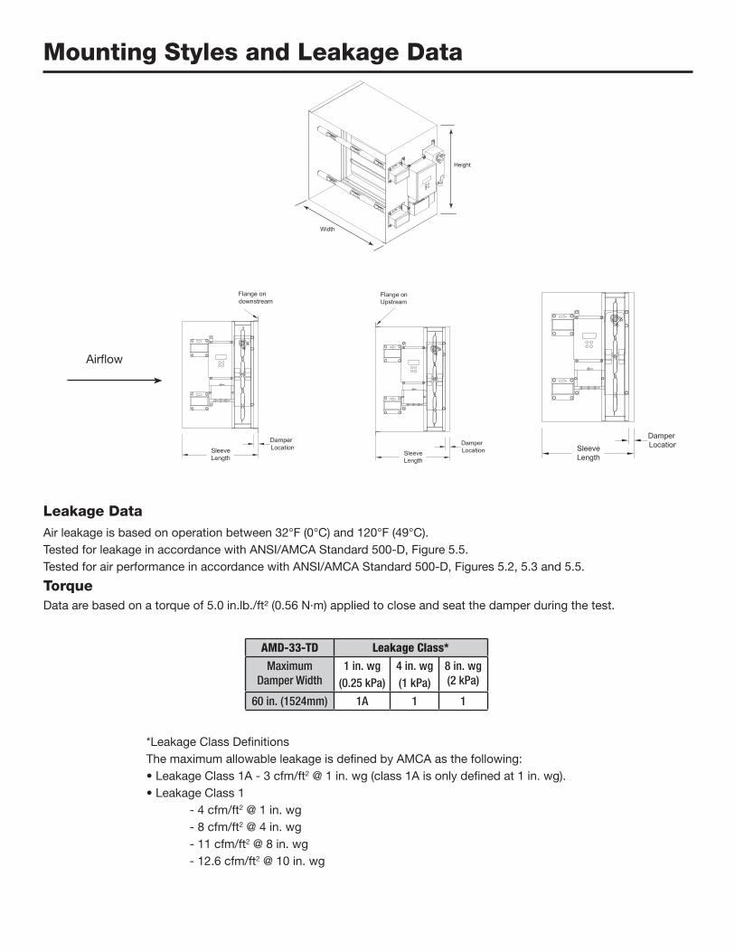
Mounting Styles and Leakage Data
Leakage DataAir leakage is based on operation between 32°F (0°C) and 120°F (49°C).Tested for leakage in accordance with ANSI/AMCA Standard 500-D, Figure 5.5.Tested for air performance in accordance with ANSI/AMCA Standard 500-D, Figures 5.2, 5.3 and 5.5.
TorqueData are based on a torque of 5.0 in.lb./ft² (0.56 N·m) applied to close and seat the damper during the test.
Height
Width
Airflow
AMD-33-TD Leakage Class*
Maximum Damper Width
1 in. wg (0.25 kPa)
4 in. wg(1 kPa)
8 in. wg (2 kPa)
60 in. (1524mm) 1A 1 1
*Leakage Class DefinitionsThe maximum allowable leakage is defined by AMCA as the following:• Leakage Class 1A - 3 cfm/ft2 @ 1 in. wg (class 1A is only defined at 1 in. wg).• Leakage Class 1 - 4 cfm/ft2 @ 1 in. wg - 8 cfm/ft2 @ 4 in. wg - 11 cfm/ft2 @ 8 in. wg - 12.6 cfm/ft2 @ 10 in. wg

Pressure Drop AMD-33-TDThis pressure drop testing was conducted in accordance with AMCA Standard 500-D using the three configurations shown. All data has been corrected to represent standard air at a density of 0.075 lb/ft3 (1.201kg/m3 ).Actual pressure drop found in any HVAC system is a combination of many factors. This pressure drop information along with an analysis of other system influences should be used to estimate actual pressure losses for a damper installed in a given HVAC system.
AMCA Test FiguresFigure 5.2 illustrates a ducted damper exhausting air into an open area. This configuration has a lower pressure drop than Figure 5.5 because entrance losses are minimized by a straight duct run upstream of the damper.
5D 6D
5D
D 4 (W) (H)3.14
5D 6D
5D
D 4 (W) (H)3.14
5D 6D
5D
D 4 (W) (H)3.14
Figure 5.3 illustrates a fully ducted damper. This configuration has the lowest pressure drop of the three test configurations because entrance and exit losses are minimized by straight duct runs upstream and downstream of the damper.
Figure 5.5 illustrates a plenum mounted damper. This configuration has the highest pressure drop because of extremely high entrance and exit losses due to the sudden changes of area in the system.

Pressure Drop Data AMD-33-TD
5D 6D
5D
D 4 (W) (H)3.14
5D 6D
5D
D 4 (W) (H)3.14
5D 6D
5D
D 4 (W) (H)3.14
AMCA 5.2
AMCA 5.3
AMCA 5.5
Velocity (fpm)Pressure Drop
(in. wg) Velocity (fpm)Pressure Drop
(in. wg) Velocity (fpm)Pressure Drop
(in. wg)
500 0.041 500 0.03 500 0.025
1000 0.131 1000 0.094 1000 0.078
1500 0.266 1500 0.189 1500 0.156
2000 0.437 2000 0.314 2000 0.259
2500 0.658 2500 0.474 2500 0.388
3000 0.927 3000 0.652 3000 0.533
3500 1.245 3500 0.876 3500 0.706
4000 1.591 4000 1.143 4000 0.914
12 in. x 12 in. (305mm x 305mm) 24 in. x 24 in. (610mm x 610mm) 36 in. x 36 in. (914mm x 914mm)
Velocity (fpm)Pressure Drop
(in. wg)
500 0.036
1000 0.102
1500 0.214
2000 0.359
2500 0.547
3000 0.772
3500 1.034
4000 1.339
48 in. x 12 in. (1219mm x 305mm)
Velocity (fpm)Pressure Drop
(in. wg)
500 0.034
1000 0.103
1500 0.213
2000 0.357
2500 0.541
3000 0.757
3500 1.017
4000 1.326
12 in. x 48 in. (305mm x 1219mm)
Velocity (fpm)Pressure Drop
(in. wg) Velocity (fpm)Pressure Drop
(in. wg) Velocity (fpm)Pressure Drop
(in. wg)
500 0.04 500 0.03 500 0.03
1000 0.12 1000 0.09 1000 0.07
1500 0.24 1500 0.17 1500 0.14
2000 0.40 2000 0.28 2000 0.23
2500 0.60 2500 0.43 2500 0.35
3000 0.84 3000 0.60 3000 0.48
3500 1.12 3500 0.80 3500 0.64
4000 1.44 4000 1.03 4000 0.82
12 in. x 12 in. (305mm x 305mm) 24 in. x 24 in. (610mm x 610mm) 36 in. x 36 in. (914mm x 914mm)
Velocity (fpm)Pressure Drop
(in. wg)
500 0.03
1000 0.09
1500 0.19
2000 0.33
2500 0.50
3000 0.71
3500 0.96
4000 1.24
48 in. x 12 in. (1219mm x 305mm)
Velocity (fpm)Pressure Drop
(in. wg)
500 0.03
1000 0.10
1500 0.20
2000 0.34
2500 0.51
3000 0.72
3500 0.97
4000 1.26
12 in. x 48 in. (305mm x 1219mm)
Velocity (fpm)Pressure Drop
(in. wg) Velocity (fpm)Pressure Drop
(in. wg) Velocity (fpm)Pressure Drop
(in. wg)
500 0.07 500 0.05 500 0.05
1000 0.24 1000 0.19 1000 0.16
1500 0.50 1500 0.38 1500 0.34
2000 0.86 2000 0.65 2000 0.57
2500 1.33 2500 1.00 2500 0.88
3000 1.89 3000 1.43 3000 1.24
3500 2.57 3500 1.90 3500 1.67
4000 3.30 4000 2.52 4000 2.19
12 in. x 12 in. (305mm x 305mm) 24 in. x 24 in. (610mm x 610mm) 36 in. x 36 in. (914mm x 914mm)
Velocity (fpm)Pressure Drop
(in. wg)
500 0.05
1000 0.19
1500 0.41
2000 0.71
2500 1.10
3000 1.55
3500 2.10
4000 2.75
48 in. x 12 in. (1219mm x 305mm)
Velocity (fpm)Pressure Drop
(in. wg)
500 0.06
1000 0.19
1500 0.41
2000 0.71
2500 1.09
3000 1.54
3500 2.08
4000 2.70
12 in. x 48 in. (305mm x 1219mm)

Copyright © 2017 Greenheck Corporation AMD-33-TD Rev. 5 May 2017
Control dampers meeting the following specifications shall be installed where shown on plans as an air monitor station integral to the minimum outside air damper. The air measuring damper shall control the minimum amount of outside air as recommended by ASHRAE Standard 62 or California Title 24.The air measuring damper shall consist of: 16 ga. (1.5mm) galvanized steel hat channel frame with 5 in. (127mm) depth; airfoil shaped, galvanized steel double skin construction blades (14 ga. (2mm) equivalent thickness). Blades shall be completely symmetrical relative to their axle pivot point, presenting identical resistance to airflow and operation in either direction through the damper (blades that are non-symmetrical relative to their axle pivot
point or utilize blade stops larger than 1⁄2 in. [13mm] are unacceptable). Axles shall be 1⁄2 in. (13mm) dia. plated steel turning in acetal bearings; TPE blade seals for 250°F (121°C) maximum temperature; flexible stainless steel jamb seals; and external (out of the airstream) blade-to-blade linkage. Vari-Green thermal dispersion probes to be installed in the damper sleeve. Transmitter and actuator to be factory wired to a terminal block for single point wiring.Damper leakage rating to be in compliance with the IECC (International Energy Conservation Code) and not to exceed 3 cfm/ft2 (55 cmh/m2) at 1 in. wg (0.25 kPa). Testing and ratings to be in accordance with AMCA standard 500-D.Basis of design is model AMD-33-TD.
Specifications AMD-33-TD