Embed Size (px)
Citation preview
®®
Vane Axial
Application and Design
May2010
2®
Introduction . . . . . . . . . . . . . . . . . . . . . . . . . . 3Definitions . . . . . . . . . . . . . . . . . . . . . . . . . . 3Vane Axial Fan Arrangements • Arrangement 4 Direct Drive . . . . . . . . . . . . . . . . . . . . 3 • Arrangement 9 Belt Drive . . . . . . . . . . . . . . . . . . . . 3Variations of Vane Axial Construction
• Hub-to-Tip Ratio . . . . . . . . . . . . . . . . . . . . . . . 4 • Half-Blade Fans . . . . . . . . . . . . . . . . . . . . . . . 4 • Two-Stage Fans . . . . . . . . . . . . . . . . . . . . . . . 5 • Fans in Parallel . . . . . . . . . . . . . . . . . . . . . . . . 5Factors Affecting Air Performance
• System Effect . . . . . . . . . . . . . . . . . . . . . . . . 6 • Air Density . . . . . . . . . . . . . . . . . . . . . . . . . 7Vane Axial Accessories Affecting Performance
• Inlet Bell . . . . . . . . . . . . . . . . . . . . . . . . . . 8 • Inlet Cone . . . . . . . . . . . . . . . . . . . . . . . . . 8 • Outlet Cone . . . . . . . . . . . . . . . . . . . . . . . . . 8Understanding Direct Drive Performance Charts . . . . . . . . . . . . . 9 • The Total Pressure Concept. . . . . . . . . . . . . . . . . . . . 9 How Outlet Conditions Affect Total, Static and Velocity Pressure . . . . . . . 10-11 • Diagram of Pressure Variations for Various Outlet Conditions . . . . . . . . . 11 Making Fan Selections
• Operating Stability . . . . . . . . . . . . . . . . . . . . . . . 12 • Avoiding Vane Axial Stall . . . . . . . . . . . . . . . . . . . . . 12 • Avoiding Motor Overload . . . . . . . . . . . . . . . . . . . . 13 • Vane Axial Efficiency . . . . . . . . . . . . . . . . . . . . . . 13Vane Axial Fans in Variable Air Volume Systems . . . . . . . . . . . . . . 13 Methods of Providing Variable Air Volume
• Two-Speed Motors . . . . . . . . . . . . . . . . . . . . . . 14 • Variable Pitch Sheaves . . . . . . . . . . . . . . . . . . . . . 14 • Inlet Vane Dampers . . . . . . . . . . . . . . . . . . . . . . 14 • Outlet Volume Dampers . . . . . . . . . . . . . . . . . . . . . 14 • Variable Frequency Drives . . . . . . . . . . . . . . . . . . . . 14Vane Axial Sound and Methods of Attenuation
• Greenheck’s Sound Trap Vane Axial . . . . . . . . . . . . . . . . . 15 • Inlet and Outlet Sound Attenuators . . . . . . . . . . . . . . . . . 15 • Acoustical Diffuser Cones . . . . . . . . . . . . . . . . . . . . 15 • Sound Absorbing Materials . . . . . . . . . . . . . . . . . . . . 16 • Fan Speed and Vane Axial Sound . . . . . . . . . . . . . . . . . . 16 • Vibration Isolators . . . . . . . . . . . . . . . . . . . . . . . 16 • Flexible Duct Connections . . . . . . . . . . . . . . . . . . . . 17 • Thrust Restraints . . . . . . . . . . . . . . . . . . . . . . . 17Economic Considerations of Vane Axial Selection and Application. . . . . . . 18-19Maintenance Costs . . . . . . . . . . . . . . . . . . . . . . . 19Specifications . . . . . . . . . . . . . . . . . . . . . . Backcover
Table of Contents
3®
INTRODUCTIONThis manual provides information on the application of vane axial fans in variable or constant air volume systems. Many problems encountered with air moving devices such as the vane axial fan, are a result of misapplication due to lack of easy to read, comprehensive and understandable information. Greenheck makes every effort to provide the customer with extensive product information. Due to the relatively high volumes, pressures and velocities generated by vane axial fans and the potential for significant performance variations, this application manual offers information for proper selection, installation and use.
DEFINITIONSAdjustable Pitch - Vane axial rotor blades may be manually adjusted to various pitches. Fan must be off, electrical power locked-out, blade retaining nuts loosened, and blades manually set to desired pitch (within horsepower limitations).
Hub - The center of the rotor. Hubs contain a provision for attachment to the driven shaft and machined sockets or holes for attaching the blades. The hub is usually covered by a nose-cone (a spun aluminum cover for streamlining the hub).
Rotor - A term used to describe the vane axial propeller. The rotor consists of a hub and blades.
Static Regain - Conversion of the energy of motion (kinetic energy) or velocity pressure to potential energy or usable static pressure. An example is the increase in static pressure as velocity is reduced across an outlet cone.
Swirl (Vortex) - Airflow rotating perpendicular to the intended axis of airflow. It is a swirling movement of air generated by the vane axial rotor.
System Effect - A pressure loss resulting from fan inlet or outlet restrictions or other condition within the system affecting fan performance. System effect is difficult to quantify and results in poor efficiency, noise and vibration.
Vane Axial Fan - An air moving device with axial airflow and straightening vanes to reduce swirl created by the rotor.
Variable Frequency Drive (VFD) - A system for controlling the rotational speed of an AC motor. Traditionally used on direct drive fans for changing the rotor speed and performance of the fan (may also be used on belt drive fans).
VANE AXIAL FAN ARRANGEMENTS
Arrangement 4 Direct DriveArrangement 4 direct drive vane axial fans have the rotor attached directly to the motor. This arrangement has several advantages over a belt drive unit in that it is more compact, has no drive losses reducing efficiency, and requires relatively little maintenance. The disadvantages include fan speeds limited to the motor speed (if used without a variable frequency drive (VFD)), poor motor accessibility, and maximum airstream temperature of 105°F using standard motor insulation. Arrangement 4 direct drive fans are available with adjustable pitch rotors and the sound trap option.
Arrangement 9 Belt DriveArrangement 9 belt drive fans are constructed with the motor mounted on the fan housing, out of the airstream. The rotor is attached to a fan shaft supported by grease lubricated bearings. A belt tube provides passage of the belts from the motor to the driven pulley. Belt drive advantages include the wide range of fan speeds available, tolerance of airstream temperatures up to 200°F, and easy motor accessibility. Also, motors for belt drive units are generally lower cost and more readily available than those in direct drive vane axials. Arrangement 9 belt drive fans are available with adjustable pitch rotors and the sound trap option.
4®
VARIATIONS OF VANE AXIAL FAN CONSTRUCTION
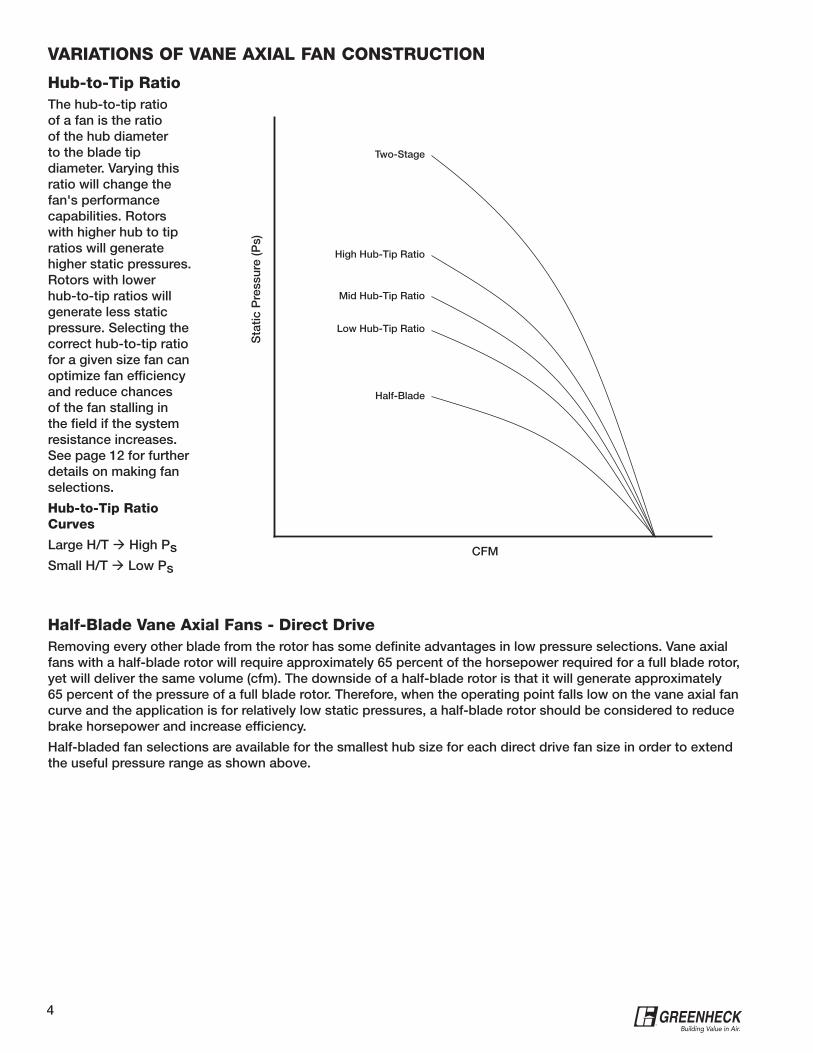
Hub-to-Tip RatioThe hub-to-tip ratio of a fan is the ratio of the hub diameter to the blade tip diameter. Varying this ratio will change the fan's performance capabilities. Rotors with higher hub to tip ratios will generate higher static pressures. Rotors with lower hub-to-tip ratios will generate less static pressure. Selecting the correct hub-to-tip ratio for a given size fan can optimize fan efficiency and reduce chances of the fan stalling in the field if the system resistance increases. See page 12 for further details on making fan selections.
Hub-to-Tip Ratio Curves
Large H/T High PsSmall H/T Low Ps
Half-Blade Vane Axial Fans - Direct DriveRemoving every other blade from the rotor has some definite advantages in low pressure selections. Vane axial fans with a half-blade rotor will require approximately 65 percent of the horsepower required for a full blade rotor, yet will deliver the same volume (cfm). The downside of a half-blade rotor is that it will generate approximately 65 percent of the pressure of a full blade rotor. Therefore, when the operating point falls low on the vane axial fan curve and the application is for relatively low static pressures, a half-blade rotor should be considered to reduce brake horsepower and increase efficiency.
Half-bladed fan selections are available for the smallest hub size for each direct drive fan size in order to extend the useful pressure range as shown above.
Two-Stage
High Hub-Tip RatioS
tatic
Pre
ssur
e (P
s)
Mid Hub-Tip Ratio
Low Hub-Tip Ratio
Half-Blade
CFM
5®
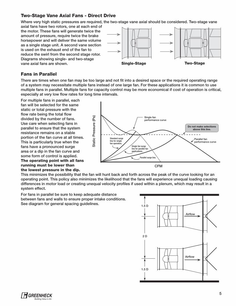
Two-Stage Vane Axial Fans - Direct DriveWhere very high static pressures are required, the two-stage vane axial should be considered. Two-stage vane axial fans have two rotors, one at each end of the motor. These fans will generate twice the amount of pressure, require twice the brake horsepower and will deliver the same volume as a single stage unit. A second vane section is used on the exhaust end of the fan to reduce the swirl from the second stage rotor. Diagrams showing single- and two-stage vane axial fans are shown. Single-Stage Two-Stage
Fans in ParallelThere are times when one fan may be too large and not fit into a desired space or the required operating range of a system may necessitate multiple fans instead of one large fan. For these applications it is common to use multiple fans in parallel. Multiple fans for capacity control may be more economical if cost of operation is critical, especially at very low flow rates for long time intervals.
For multiple fans in parallel, each fan will be selected for the same static or total pressure with the flow rate being the total flow divided by the number of fans. Use care when selecting fans in parallel to ensure that the system resistance remains on a stable portion of the fan curve at all times. This is particularly true when the fans have a pronounced surge area or a dip in the fan curve and some form of control is applied. The operating point with all fans running must be lower than the lowest pressure in the dip. This minimizes the possibility that the fan will hunt back and forth across the peak of the curve looking for an operating point. This policy also minimizes the likelihood that the fans will experience unequal loading causing differences in motor load or creating unequal velocity profiles if used within a plenum, which may result in a system effect.
For fans in parallel be sure to keep adequate distance between fans and walls to ensure proper intake conditions. See diagram for general spacing guidelines.
2 D
1.5 D
Airflow
Airflow
1.5 D
Sta
tic P
ress
ure
(Ps)
CFM
Single fan performance curve
Parallel fanperformance curve
Standard surge line for single fan operation.
Single fan surgeline for parallel fan applications.
Parallel surge line.
Do not make selectionsabove this line.
6®
FACTORS AFFECTING AIR PERFORMANCE
System EffectImagine a vane axial fan selected with great care to provide exactly the performance required in the specifications. Once installed, the air balancer reports that air performance is considerably lower than required. What went wrong?
The answer is probably system effect. The Air Movement and Control Association International Inc. (AMCA) defines system effect as "a pressure loss which recognized the effect of fan inlet restrictions, fan outlet restrictions, or other conditions influencing fan performance when installed in the system."
Fan manufacturers go to great lengths to test fans and provide reliable air performance data in their literature. These fans are tested under very specific conditions as specified on the performance pages. Statements such as, "Performance shown is for model 'xyz' with inlet and outlet ducts," indicate how the fan was tested. An installation where elbows, transitions, dampers and other disruptions to airflow are located before or after the fan can create a condition different from the manufacturer's test methods. Therefore, a performance loss or system effect is created.
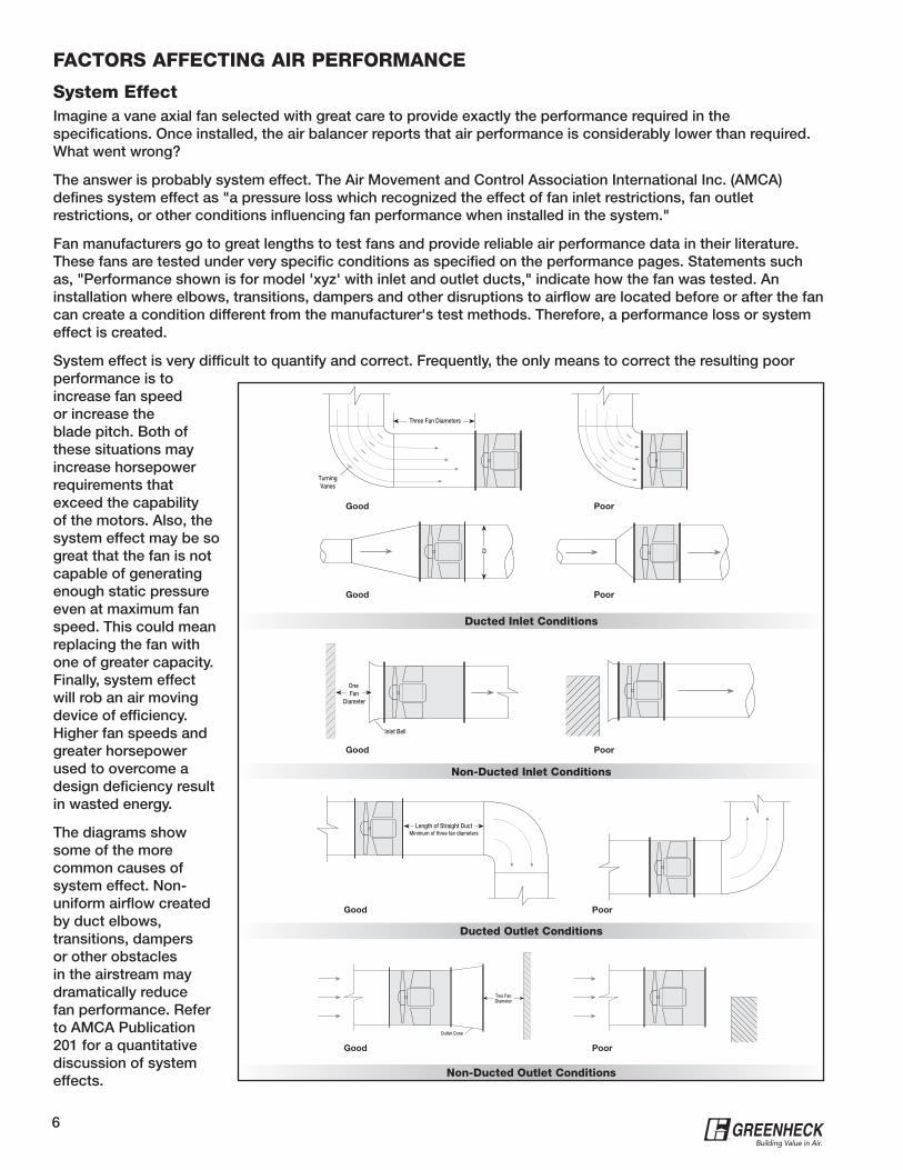
System effect is very difficult to quantify and correct. Frequently, the only means to correct the resulting poor performance is to increase fan speed or increase the blade pitch. Both of these situations may increase horsepower requirements that exceed the capability of the motors. Also, the system effect may be so great that the fan is not capable of generating enough static pressure even at maximum fan speed. This could mean replacing the fan with one of greater capacity. Finally, system effect will rob an air moving device of efficiency. Higher fan speeds and greater horsepower used to overcome a design deficiency result in wasted energy.
The diagrams show some of the more common causes of system effect. Non-uniform airflow created by duct elbows, transitions, dampers or other obstacles in the airstream may dramatically reduce fan performance. Refer to AMCA Publication 201 for a quantitative discussion of system effects.
One Fan
Diameter
Inlet Bell
Three Fan Diameters
TurningVanes
D
Ducted Inlet Conditions
Good
Good
Poor
Poor
Good
Good
Good
Poor
Poor
Poor
Length of Straight DuctMinimum of three fan diameters
Two FanDiameter
Outlet Cone
Non-Ducted Inlet Conditions
Ducted Outlet Conditions
Non-Ducted Outlet Conditions
7®
Air DensityAir density is a function of elevation and temperature, and both variables affect fan air performance. Air density will affect the total pressure that a fan can generate and the horsepower required to move the air.
Most fan performance is published at a density based on air at 70°F and at sea level. This is referred to as “standard air.” The resulting density is 0.075 Ibs. per cubic foot.
A fan operating at a higher elevation or temperature will move the SAME VOLUME of air as it will at standard conditions, however, it will generate LESS TOTAL PRESSURE and will require LESS HORSEPOWER.
When selecting a vane axial fan to operate at a non-standard density using standard air density tables and curves, corrections must be made to the parameters affected by air density. These parameters are static pressure and brake horsepower.
At higher than standard elevations and temperatures, air density will be lower than standard. Therefore, we must determine the static pressure at standard air density that will equate to the specified static pressure at our operating density. Since standard air density is greater than operating air density in this case, we would expect the corrected static pressure to be greater than the operating static pressure.
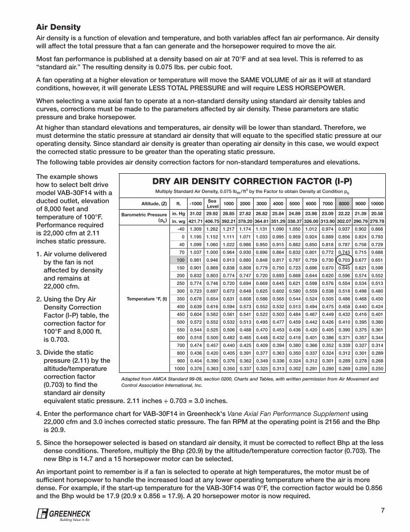
The following table provides air density correction factors for non-standard temperatures and elevations.
DRY AIR DENSITY CORRECTION FACTOR (I-P)Multiply Standard Air Density, 0.075 lbm / ft
3 by the Factor to obtain Density at Condition pb
Altitude, (Z) ft. -1000Sea
Level1000 2000 3000 4000 5000 6000 7000 8000 9000 10000
Barometric Pressure
( pb )
in. Hg 31.02 29.92 28.85 27.82 26.82 25.84 24.89 23.98 23.09 22.22 21.39 20.58
in. wg 421.71 406.75 392.21 378.20 364.61 351.29 338.37 326.00 313.90 302.07 290.79 279.78
Temperature °F, (t)
-40 1.309 1.262 1.217 1.174 1.131 1.090 1.050 1.012 0.974 0.937 0.902 0.868
0 1.195 1.152 1.111 1.071 1.033 0.995 0.959 0.924 0.889 0.856 0.824 0.793
40 1.099 1.060 1.022 0.986 0.950 0.915 0.882 0.850 0.818 0.787 0.758 0.729
70 1.037 1.000 0.964 0.930 0.896 0.864 0.832 0.801 0.772 0.743 0.715 0.688
100 0.981 0.946 0.913 0.880 0.848 0.817 0.787 0.759 0.730 0.703 0.677 0.651
150 0.901 0.869 0.838 0.808 0.779 0.750 0.723 0.696 0.670 0.645 0.621 0.598
200 0.832 0.803 0.774 0.747 0.720 0.693 0.668 0.644 0.620 0.596 0.574 0.552
250 0.774 0.746 0.720 0.694 0.669 0.645 0.621 0.598 0.576 0.554 0.534 0.513
300 0.723 0.697 0.672 0.648 0.625 0.602 0.580 0.559 0.538 0.518 0.498 0.480
350 0.678 0.654 0.631 0.608 0.586 0.565 0.544 0.524 0.505 0.486 0.468 0.450
400 0.639 0.616 0.594 0.573 0.552 0.532 0.513 0.494 0.475 0.458 0.440 0.424
450 0.604 0.582 0.561 0.541 0.522 0.503 0.484 0.467 0.449 0.432 0.416 0.401
500 0.572 0.552 0.532 0.513 0.495 0.477 0.459 0.442 0.426 0.410 0.395 0.380
550 0.544 0.525 0.506 0.488 0.470 0.453 0.436 0.420 0.405 0.390 0.375 0.361
600 0.518 0.500 0.482 0.465 0.448 0.432 0.416 0.401 0.386 0.371 0.357 0.344
700 0.474 0.457 0.440 0.425 0.409 0.394 0.380 0.366 0.352 0.339 0.327 0.314
800 0.436 0.420 0.405 0.391 0.377 0.363 0.350 0.337 0.324 0.312 0.301 0.289
900 0.404 0.390 0.376 0.362 0.349 0.336 0.324 0.312 0.301 0.289 0.278 0.268
1000 0.376 0.363 0.350 0.337 0.325 0.313 0.302 0.291 0.280 0.269 0.259 0.250
Adapted from AMCA Standard 99-09, section 0200, Charts and Tables, with written permission from Air Movement and Control Association International, Inc.
The example shows how to select belt drive model VAB-30F14 with a ducted outlet, elevation of 8,000 feet and temperature of 100°F. Performance required is 22,000 cfm at 2.11 inches static pressure.
1. Air volume delivered by the fan is not affected by density and remains at 22,000 cfm.
2. Using the Dry Air Density Correction Factor (I-P) table, the correction factor for 100°F and 8,000 ft. is 0.703.
3. Divide the static pressure (2.11) by the altitude/temperature correction factor (0.703) to find the standard air density equivalent static pressure. 2.11 inches ÷ 0.703 = 3.0 inches.
4. Enter the performance chart for VAB-30F14 in Greenheck's Vane Axial Fan Performance Supplement using 22,000 cfm and 3.0 inches corrected static pressure. The fan RPM at the operating point is 2156 and the Bhp is 20.9.
5. Since the horsepower selected is based on standard air density, it must be corrected to reflect Bhp at the less dense conditions. Therefore, multiply the Bhp (20.9) by the altitude/temperature correction factor (0.703). The new Bhp is 14.7 and a 15 horsepower motor can be selected.
An important point to remember is if a fan is selected to operate at high temperatures, the motor must be of sufficient horsepower to handle the increased load at any lower operating temperature where the air is more dense. For example, if the start-up temperature for the VAB-30F14 was 0°F, the correction factor would be 0.856 and the Bhp would be 17.9 (20.9 x 0.856 = 17.9). A 20 horsepower motor is now required.
8®
VANE AXIAL ACCESSORIES AFFECTING AIR PERFORMANCE
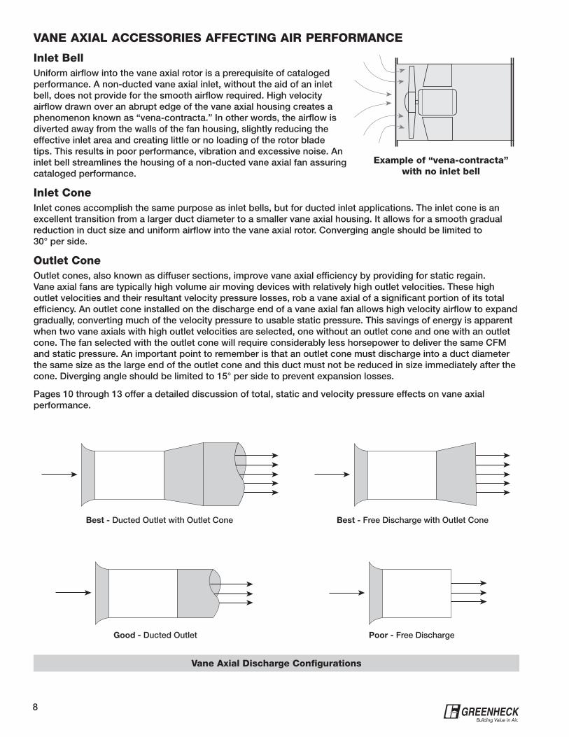
Inlet BellUniform airflow into the vane axial rotor is a prerequisite of cataloged performance. A non-ducted vane axial inlet, without the aid of an inlet bell, does not provide for the smooth airflow required. High velocity airflow drawn over an abrupt edge of the vane axial housing creates a phenomenon known as “vena-contracta.” In other words, the airflow is diverted away from the walls of the fan housing, slightly reducing the effective inlet area and creating little or no loading of the rotor blade tips. This results in poor performance, vibration and excessive noise. An inlet bell streamlines the housing of a non-ducted vane axial fan assuring cataloged performance.
Inlet ConeInlet cones accomplish the same purpose as inlet bells, but for ducted inlet applications. The inlet cone is an excellent transition from a larger duct diameter to a smaller vane axial housing. It allows for a smooth gradual reduction in duct size and uniform airflow into the vane axial rotor. Converging angle should be limited to 30° per side.
Outlet ConeOutlet cones, also known as diffuser sections, improve vane axial efficiency by providing for static regain. Vane axial fans are typically high volume air moving devices with relatively high outlet velocities. These high outlet velocities and their resultant velocity pressure losses, rob a vane axial of a significant portion of its total efficiency. An outlet cone installed on the discharge end of a vane axial fan allows high velocity airflow to expand gradually, converting much of the velocity pressure to usable static pressure. This savings of energy is apparent when two vane axials with high outlet velocities are selected, one without an outlet cone and one with an outlet cone. The fan selected with the outlet cone will require considerably less horsepower to deliver the same CFM and static pressure. An important point to remember is that an outlet cone must discharge into a duct diameter the same size as the large end of the outlet cone and this duct must not be reduced in size immediately after the cone. Diverging angle should be limited to 15° per side to prevent expansion losses.
Pages 10 through 13 offer a detailed discussion of total, static and velocity pressure effects on vane axial performance.
Example of “vena-contracta” with no inlet bell
Vane Axial Discharge Configurations
Best - Ducted Outlet with Outlet Cone
Good - Ducted Outlet
Best - Free Discharge with Outlet Cone
Poor - Free Discharge
9®
UNDERSTANDING DIRECT DRIVE VANE AXIAL PERFORMANCE CHARTSBecause of overlapping performance, numerous variables affecting fan performance, and a requirement to select vane axial fans using total pressure instead of static pressure, traditional fan selection charts using static pressure and CFM are unsuitable. Instead, direct drive vane axial fans are selected from charts containing fan curves for several blade pitch settings.
In addition to fan curves, each chart contains variables for CFM, velocity pressure, total pressure, brake horsepower, outlet velocity and efficiency.
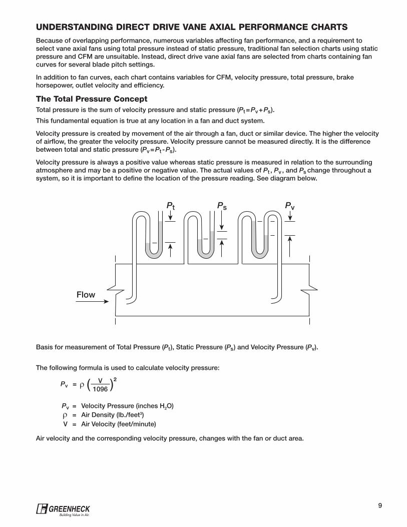
The Total Pressure ConceptTotal pressure is the sum of velocity pressure and static pressure (Pt = Pv + Ps ).
This fundamental equation is true at any location in a fan and duct system.
Velocity pressure is created by movement of the air through a fan, duct or similar device. The higher the velocity of airflow, the greater the velocity pressure. Velocity pressure cannot be measured directly. It is the difference between total and static pressure (Pv = Pt - Ps ).
Velocity pressure is always a positive value whereas static pressure is measured in relation to the surrounding atmosphere and may be a positive or negative value. The actual values of Pt , Pv , and Ps change throughout a system, so it is important to define the location of the pressure reading. See diagram below.
Pv = ( V )21096
Pv = Velocity Pressure (inches H2O)= Air Density (lb./feet3)
V = Air Velocity (feet/minute)
Air velocity and the corresponding velocity pressure, changes with the fan or duct area.
The following formula is used to calculate velocity pressure:
Basis for measurement of Total Pressure (Pt ), Static Pressure (Ps ) and Velocity Pressure (Pv).
Flow
PsPt Pv
10®
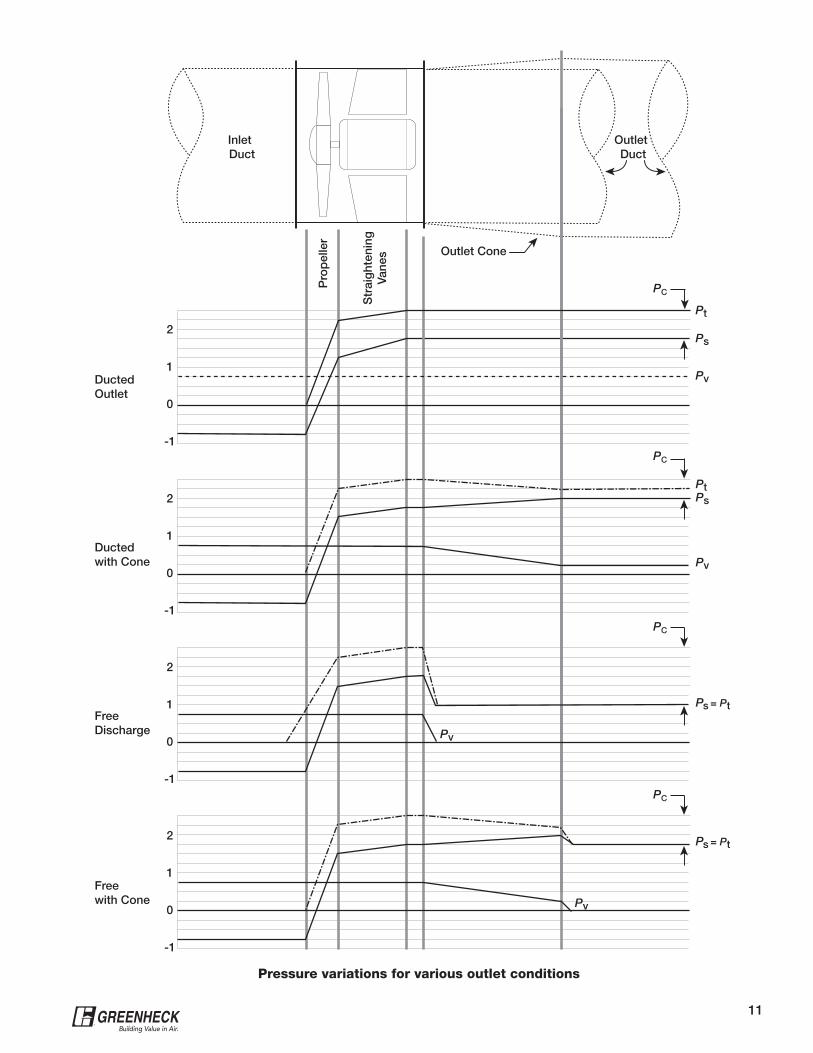
HOW OUTLET CONDITIONS AFFECT TOTAL, STATIC, AND VELOCITY PRESSUREThe purpose of a fan in an air movement system is to increase the total pressure of the system. This total pressure rise takes place primarily in the fan propeller, but additionally in the straightening vane section as swirling air velocity is converted to static pressure. The total pressure rise in the fan is used to overcome system resistance losses as well as losses due to outlet conditions.
The outlet losses change with different outlet configurations and are illustrated on the opposing page. When looking at the fluctuations in pressures through the various outlet conditions, it is important to remember that the total pressure is always equal to the sum of the static and velocity pressures. The curves show typical performance only and are used to show changes in the pressure values. If a free inlet is required, the inlet duct can be replaced with an inlet bell which provides a smooth transition to the fan velocity with no loss in total pressure.
The Ducted Outlet configuration results in the highest value of total pressure rise. The constant area of the duct connection eliminates any expansion losses. Expansion losses occur whenever air is forced to expand and slow down into a larger area. Some expansion losses are present within the fan, as the air expands around the back side of the motor to fill the entire fan area. This loss is ignored in these examples for simplicity, but is included in published performance values.
The slight drop in total pressure through the outlet cone in the Ducted with Cone situation is an expansion loss due to the increasing area of the cone. This loss is kept to a minimum by using a cone with a diverging angle of 15 degrees. The advantage of using an outlet cone, however, can be seen in the conversion of velocity pressure to usable static pressure. This is referred to as static regain and the result is lower fan Bhp for a given static pressure. An additional benefit is reduced duct resistance due to the lower duct velocity.
When the air undergoes a large expansion, as in a Free Discharge into a plenum or the atmosphere, the expansion loss becomes significant. In this case, velocity pressure is reduced to approximately zero, since the area is very large. However, none of this velocity pressure is converted to static pressure, in fact, the static pressure also drops since the expansion is so sudden. Total pressure is equal to static pressure at the discharge, since velocity pressure drops to zero.
The addition of an outlet cone in a free discharge, Free with Cone, is beneficial for two reasons. First, some static regain takes place in the outlet cone, similar to the ducted with cone situation. Secondly, since the air has already expanded and slowed down through the outlet cone, the expansion loss at the cone’s discharge is not as high as it would be at the fan outlet. Therefore, due to its dramatic effect on outlet static pressure, an outlet cone should be used whenever possible with a free discharge.
11®
Pressure variations for various outlet conditions
DuctedOutlet
Inlet Duct
Pro
pel
ler
Str
aig
hten
ing
Vane
s Outlet Cone
Outlet Duct
Ductedwith Cone
FreeDischarge
Freewith Cone
2
1
0
-1
2
1
0
-1
2
1
0
-1
2
1
0
-1
PC
PC
PC
PC
Pt
Ps
Pv
PtPs
Pv
Pv
Pv
Ps = Pt
Ps = Pt
12®
MAKING FAN SELECTIONSGreenheck vane axial fans were tested using an inlet bell to simulate a ducted inlet and an outlet duct with a diameter equal to the fan diameter. The curves are plotted in total pressure for various blade pitches and RPM’s.
In order to convert static pressure at any of the four outlet conditions to the published total pressure with ducted outlet, a pressure correction (Pc) is used. Pc is defined as the difference between ducted total pressure and static pressure in the duct or plenum. The pressure correction includes any static regain through outlet cones, as well as expansion losses in outlet cones and in free discharges. Pc should not be confused with velocity pressure, since they are equal only in the case of a ducted outlet. Values of Pc can be determined from Outlet Condition Corrections charts on each page of the Vane Axial Fan Performance Supplement.
It is important to consider outlet conditions when selecting a Greenheck vane axial fan to ensure the required performance will be met when installed. It is also important to consider outlet conditions when comparing the performance of different manufacturers. Some manufacturers publish a “stage” total pressure, or a total pressure increase from the inlet of the fan to a point in the straightening vanes just prior to the expansion into the center portion of the fan. By considering this expansion loss as part of their outlet condition correction, they are able to publish a higher total pressure (and total efficiency) than is physically possible, even with a ducted outlet. Since stage total pressure is not the same as fan total pressure, static pressure in the duct or plenum should be used as a means of fan selection when making comparisons between manufacturers.
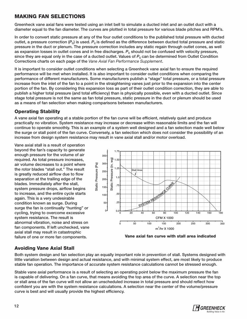
Operating StabilityA vane axial fan operating at a stable portion of the fan curve will be efficient, relatively quiet and produce practically no vibration. System resistance may increase or decrease within reasonable limits and the fan will continue to operate smoothly. This is an example of a system well designed and a fan selection made well below the surge or stall point of the fan curve. Conversely, a fan selection which does not consider the possibility of an increase from design system resistance may result in vane axial stall and/or motor overload.
Vane axial stall is a result of operation beyond the fan’s capacity to generate enough pressure for the volume of air required. As total pressure increases, air volume decreases to a point where the rotor blades “stall out.” The result is greatly reduced airflow due to flow separation at the trailing edge of the blades. Immediately after the stall, system pressure drops, airflow begins to increase, and the entire cycle starts again. This is a very undesirable condition known as surge. During surge the fan is continually “hunting” or cycling, trying to overcome excessive system resistance. The result is abnormal vibration, noise and stress on fan components. If left unchecked, vane axial stall may result in catastrophic failure of one or more fan components.
Avoiding Vane Axial StallBoth system design and fan selection play an equally important role in prevention of stall. Systems designed with little variation between design and actual resistance, and with minimal system effect, are most likely to produce stable fan operation. The importance of accurate system resistance calculations cannot be stressed enough.
Stable vane axial performance is a result of selecting an operating point below the maximum pressure the fan is capable of delivering. On a fan curve, that means avoiding the top area of the curve. A selection near the top or stall area of the fan curve will not allow an unscheduled increase in total pressure and should reflect how confident you are with the system resistance calculations. A selection near the center of the volume/pressure curve is best and will usually provide the highest efficiency.
0 20 40 60 80 100 120 140 1600.0
.25
.50
.75
1.25
1.50
1.75
180
1.0
SYSTEM RESISTANCE C
URVE
0 50 100 150 200 250 300
0
50
100
150
200
250
300
350
CFM X 1000
m3/hr X 1000
Sta
tic P
ress
ure
(Pa)
350
Sta
tic P
ress
ure
(in. w
g)
Stall Area
Vane axial fan curve with stall area indicated
13®
Avoiding Motor OverloadSpecifying the correct motor horsepower is a very important part of selecting a vane axial fan. A motor selected with no margin for error in design system static pressure may be short lived. Higher than anticipated system static pressure may overload the motor and lead to eventual failure. Additionally, the correct horsepower must be selected for a specific fan RPM. This is usually not a problem with direct drive vane axial fans but with belt drive units an increase in fan RPM can easily result in motor overload. It is a good policy to consult the factory before attempting to increase fan speed on any vane axial fan.
On direct drive vane axial fans, brake horsepower can usually be increased into the motor service factor. Airflow over the motor creates a cooling effect and operation into the service factor, typically a factor of 1.15, is allowed. For example, with adequate cooling a 10 hp motor is capable of delivering 11.5 Bhp with no reduction in service life. However, a note of caution here – electrical supply wiring, circuit protection and switches must be capable of handling the increased electrical load.
If a fan RPM increase is required, refer to the appropriate performance chart and select brake horsepower required at the new operating point. After the speed change is made, always check motor load amperage and compare it to the motor nameplate rating.
Vane Axial EfficiencyOne reason for specifying a vane axial fan is its efficient operation. The straight-through airflow, minimal discharge vortex and static regain available from a vane axial fan make it a very desirable air moving device. Total efficiencies from 70 to 80 percent are not uncommon for fans with a good operating point.
However, oversights in the selection process can have a detrimental affect on fan efficiency. First, fan size has an affect on efficiency. Selecting too small a fan will increase air velocity and create excessive pressure losses. To overcome these losses a larger motor is necessary. Here we have two detrimental effects: high pressure losses and inefficient unit size. Secondly, choosing the wrong hub-to-tip ratio will reduce efficiency. For relatively large air volumes at low total pressures, try to select a small hub in relation to the fin tip diameter. Smaller hubs mean longer rotor blades, which will move a greater volume of air at relatively low fan speeds. For performance requirements with relatively low volumes at high total pressures, try to select a large hub with relation to the fin tip diameter. A large hub with short rotor blades, turning at high fan RPM, will generate the high total pressures required.
VANE AXIAL FANS IN VARIABLE AIR VOLUME SYSTEMSVariable air volume (VAV) systems are quite common in the HVAC industry. Ventilation, heating and cooling demands in a building will vary significantly in 24 hours because of occupancy and outside air temperature. It makes economical sense to reduce the ventilation, heating or cooling at night when the building is not occupied. Conversely, during peak business hours maximum HVAC usage can be expected. A variable air volume system makes this all possible. Vane axial fans with variable frequency drives are highly suited to variable air volume systems.
14®
METHODS OF PROVIDING VARIABLE AIR VOLUMETwo-Speed Motors - Motors used in direct or belt drive vane axial fans are typically available with one-third or one-half speed reduction. This in turn will provide a corresponding air volume reduction of one-third or one-half.
Variable Pitch Sheaves - Belt drive vane axial fans with variable pitch motor sheaves provide changeable air volume, but only after stopping the fan and mechanically adjusting the sheave. In addition to being inconvenient, adjustable motor sheaves should not be used on motors over 25 horsepower because of excessive weight and possible imbalance.
Inlet Vane Dampers - Variable inlet vanes provide airflow modulation, but should not be used for vane axial fans because of high pressures and velocities. Inlet vanes create a swirl into the fan inlet, which reduces airflow and power requirements. A pressure drop results from airflow resistance through the inlet vane assembly and reduces performance.
Outlet Volume Dampers - Outlet volume dampers are seldom used for variable air volume control with vane axial fans. High pressures and velocities require use of heavy-duty industrial-type dampers which are costly and inefficient. Using an outlet volume damper on a propeller type fan—such as the vane axial—can increase horsepower requirements, overload the motor, and result in eventual motor burnout.
Variable Frequency Drives - Varying motor speed with a variable frequency drive provides a very efficient means of modulating airflow. The motor speed is varied electrically and airflow is varied proportional to fan speed. Advantages of using a variable frequency drive are reliable, precise microprocessor control of motor speed and long-term energy savings resulting from fan operation at reduced horsepower levels. A preset pitch fan with a variable frequency drive has no additional moving parts and theoretically should be very reliable. As fan speed is lowered, brake horsepower is reduced by the cube of the speed ratio and results in significant energy savings.
One disadvantage of varying fan speed is that fan performance follows a system resistance line on the fan curve, meaning that pressure varies with the square of the fan speed ratio. In other words, if you want to keep the system pressure and only vary the air volume, it cannot be done. While this is an efficient means of varying air volume, it is not suited for all applications. Varying fan speed in order to vary air volume is not suitable for a system which requires constant pressure.
One special note regarding variable frequency drives for use with explosion-proof motors: The variable frequency drive and explosion-proof motor must be UL listed together as a complete system when they are used in a hazardous environment.
VANE AXIAL SOUND AND METHODS OF ATTENUATION
Vane axial sound power levels in the upper octave bands are typically higher than other axial and centrifugal fans. The following example (40,000 cfm and 2.0 inches static pressure) shows how sound power levels and frequencies compare between a 60 inch vane axial and a 60 inch single width centrifugal fan.
As shown above, it is apparent that a vane axial fan is louder in the higher frequency bands. Consequently, one of the first steps in controlling vane axial sound is consideration of these high frequencies in system design. A vane axial fan located in an equipment room directly above the chief executive officer’s suite would not be an example of good system design.
Although vane axial fans generate high frequency sound, it is the easiest to attenuate. Reducing the high frequencies of a vane axial fan is relatively simple compared to the low frequency rumble generated by large centrifugal fans. A choice of many different methods of reducing vane axial sound is available to the system designer. The following section discusses various methods of attenuation.
Octave Band 1 2 3 4 5 6 7 8
Center Frequency (Hz) 63 125 250 500 1000 2000 4000 8000
Vane Axial (dB) 91 97 99 98 95 91 86 81
Centrifugal (dB) 96 91 86 83 78 74 70 65
Sound power comparison of a VAB-60F26 vane axial fan and a 60-BISW centrifugal fan
15®
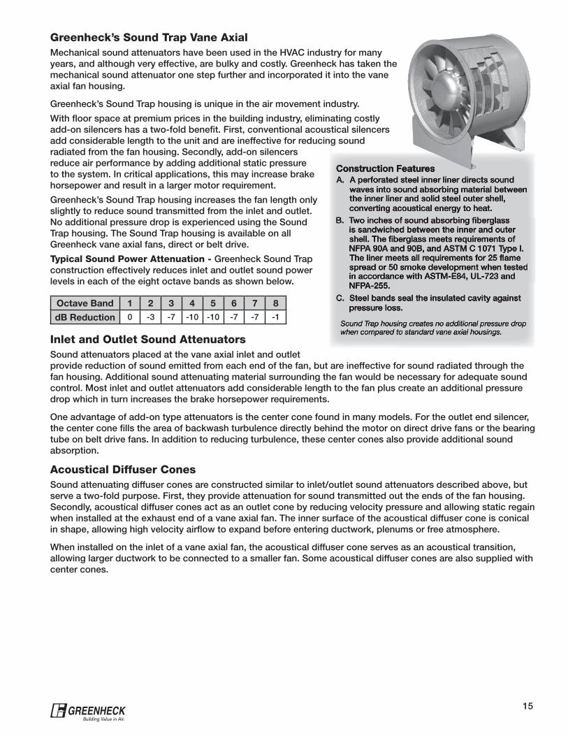
Greenheck’s Sound Trap Vane AxialMechanical sound attenuators have been used in the HVAC industry for many years, and although very effective, are bulky and costly. Greenheck has taken the mechanical sound attenuator one step further and incorporated it into the vane axial fan housing.
Greenheck’s Sound Trap housing is unique in the air movement industry.
With floor space at premium prices in the building industry, eliminating costly add-on silencers has a two-fold benefit. First, conventional acoustical silencers add considerable length to the unit and are ineffective for reducing sound radiated from the fan housing. Secondly, add-on silencers reduce air performance by adding additional static pressure to the system. In critical applications, this may increase brake horsepower and result in a larger motor requirement.
Greenheck’s Sound Trap housing increases the fan length only slightly to reduce sound transmitted from the inlet and outlet. No additional pressure drop is experienced using the Sound Trap housing. The Sound Trap housing is available on all Greenheck vane axial fans, direct or belt drive.
Typical Sound Power Attenuation - Greenheck Sound Trap construction effectively reduces inlet and outlet sound power levels in each of the eight octave bands as shown below.
Inlet and Outlet Sound AttenuatorsSound attenuators placed at the vane axial inlet and outlet provide reduction of sound emitted from each end of the fan, but are ineffective for sound radiated through the fan housing. Additional sound attenuating material surrounding the fan would be necessary for adequate sound control. Most inlet and outlet attenuators add considerable length to the fan plus create an additional pressure drop which in turn increases the brake horsepower requirements.
One advantage of add-on type attenuators is the center cone found in many models. For the outlet end silencer, the center cone fills the area of backwash turbulence directly behind the motor on direct drive fans or the bearing tube on belt drive fans. In addition to reducing turbulence, these center cones also provide additional sound absorption.
Acoustical Diffuser ConesSound attenuating diffuser cones are constructed similar to inlet/outlet sound attenuators described above, but serve a two-fold purpose. First, they provide attenuation for sound transmitted out the ends of the fan housing. Secondly, acoustical diffuser cones act as an outlet cone by reducing velocity pressure and allowing static regain when installed at the exhaust end of a vane axial fan. The inner surface of the acoustical diffuser cone is conical in shape, allowing high velocity airflow to expand before entering ductwork, plenums or free atmosphere.
When installed on the inlet of a vane axial fan, the acoustical diffuser cone serves as an acoustical transition, allowing larger ductwork to be connected to a smaller fan. Some acoustical diffuser cones are also supplied with center cones.
Octave Band 1 2 3 4 5 6 7 8
dB Reduction 0 -3 -7 -10 -10 -7 -7 -1
16®
Sound Absorbing MaterialsA variety of sound absorbing materials such as fiberglass, foam, perforated metal panels, quilted fiberglass, and asphaltic mastic are available from manufacturers of noise control products. Some of these products can be wrapped around the vane axial fan housing and associated ductwork to reduce radiated sound. Other methods of application would be to line an equipment room or adjacent wall with acoustical foam tiles. Since the high frequencies emitted by vane axial fans are easily attenuated, these materials can be very effective.
Fan Speed and Vane Axial SoundWhen sound is an important consideration in vane axial application, fan speed must be analyzed carefully. For a given duty it is much wiser to select a larger fan at lower RPM and low sound power levels than a small fan at a high RPM. Small vane axial fans operating at high fan RPM’s present two problems. First, high rotor blade tip speeds create excessive high frequency sound power levels. Secondly, high velocities created by a small fan housing generate an abundance of air noise. Of course, high total pressures and operating stability may not allow selection of a larger vane axial with lower fan RPM.
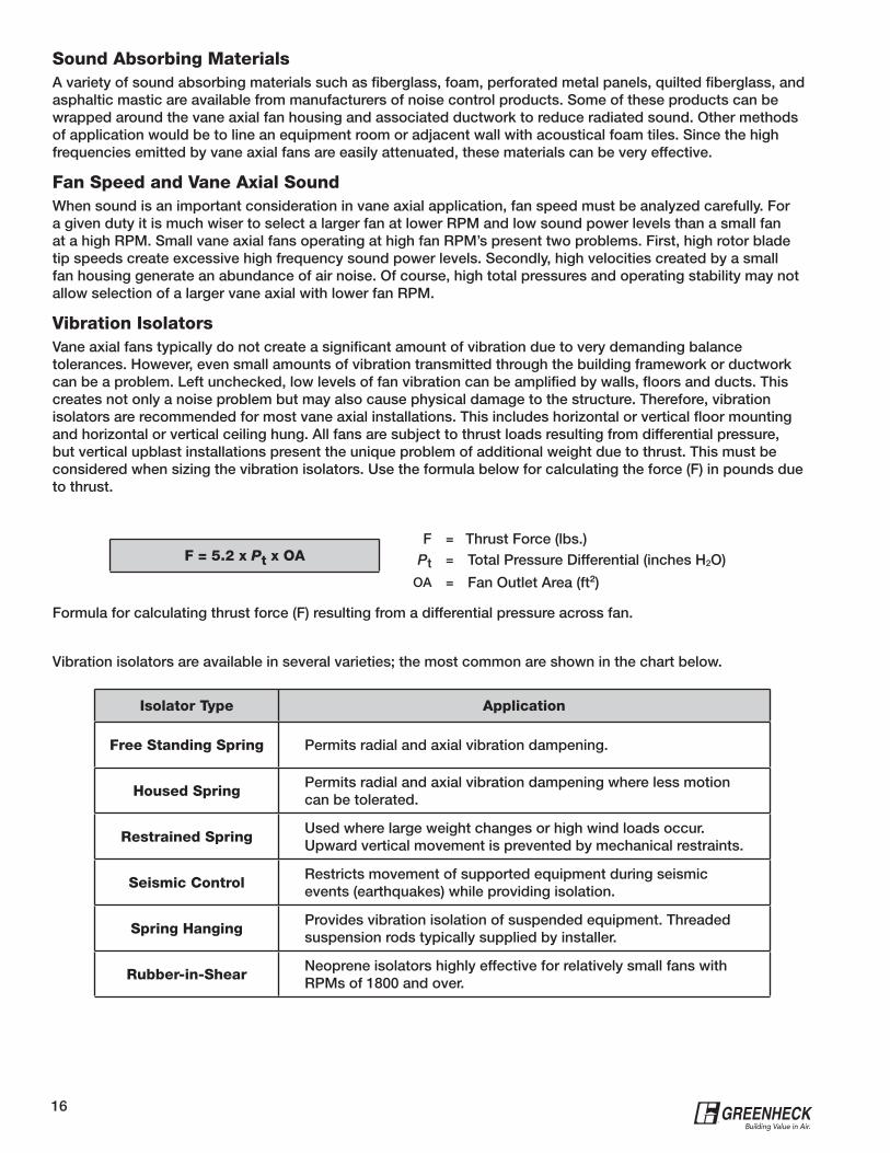
Vibration IsolatorsVane axial fans typically do not create a significant amount of vibration due to very demanding balance tolerances. However, even small amounts of vibration transmitted through the building framework or ductwork can be a problem. Left unchecked, low levels of fan vibration can be amplified by walls, floors and ducts. This creates not only a noise problem but may also cause physical damage to the structure. Therefore, vibration isolators are recommended for most vane axial installations. This includes horizontal or vertical floor mounting and horizontal or vertical ceiling hung. All fans are subject to thrust loads resulting from differential pressure, but vertical upblast installations present the unique problem of additional weight due to thrust. This must be considered when sizing the vibration isolators. Use the formula below for calculating the force (F) in pounds due to thrust.
Isolator Type Application
Free Standing Spring Permits radial and axial vibration dampening.
Housed SpringPermits radial and axial vibration dampening where less motion can be tolerated.
Restrained SpringUsed where large weight changes or high wind loads occur. Upward vertical movement is prevented by mechanical restraints.
Seismic ControlRestricts movement of supported equipment during seismic events (earthquakes) while providing isolation.
Spring HangingProvides vibration isolation of suspended equipment. Threaded suspension rods typically supplied by installer.
Rubber-in-ShearNeoprene isolators highly effective for relatively small fans with RPMs of 1800 and over.
F = Thrust Force (lbs.)Pt = Total Pressure Differential (inches H2O)
OA = Fan Outlet Area (ft²)
F = 5.2 x Pt x OA
Vibration isolators are available in several varieties; the most common are shown in the chart below.
Formula for calculating thrust force (F) resulting from a differential pressure across fan.
17®
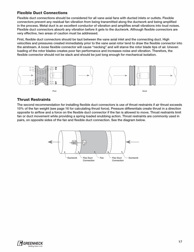
Flexible Duct ConnectionsFlexible duct connections should be considered for all vane axial fans with ducted inlets or outlets. Flexible connectors prevent any residual fan vibration from being transmitted along the ductwork and being amplified in the process. Metal duct is an excellent conductor of vibration and amplifies small vibrations into loud noises. Flexible duct connectors absorb any vibration before it gets to the ductwork. Although flexible connectors are very effective, two areas of caution must be addressed.
First, flexible duct connectors should be taut between the vane axial inlet and the connecting duct. High velocities and pressures created immediately prior to the vane axial rotor tend to draw the flexible connector into the airstream. A loose flexible connector will cause “necking” and will starve the rotor blade tips of air. Uneven loading of the rotor blades creates poor fan performance and increases noise and vibration. Therefore, the flexible connector should not be slack and should be just long enough for mechanical isolation.
Thrust RestraintsThe second recommendation for installing flexible duct connectors is use of thrust restraints if air thrust exceeds 10% of the fan weight (see page 16 for calculating thrust force). Pressure differentials create thrust in a direction opposite to airflow and a force on the flexible duct connector if the fan is allowed to move. Thrust restraints limit fan or duct movement while providing a spring loaded snubbing action. Thrust restraints are commonly used in pairs, on opposite sides of the fan and flexible duct connection. See the diagram below.
Poor Good
Ductwork Flex DuctConnection
DuctworkFlex DuctConnection
Fan
18®
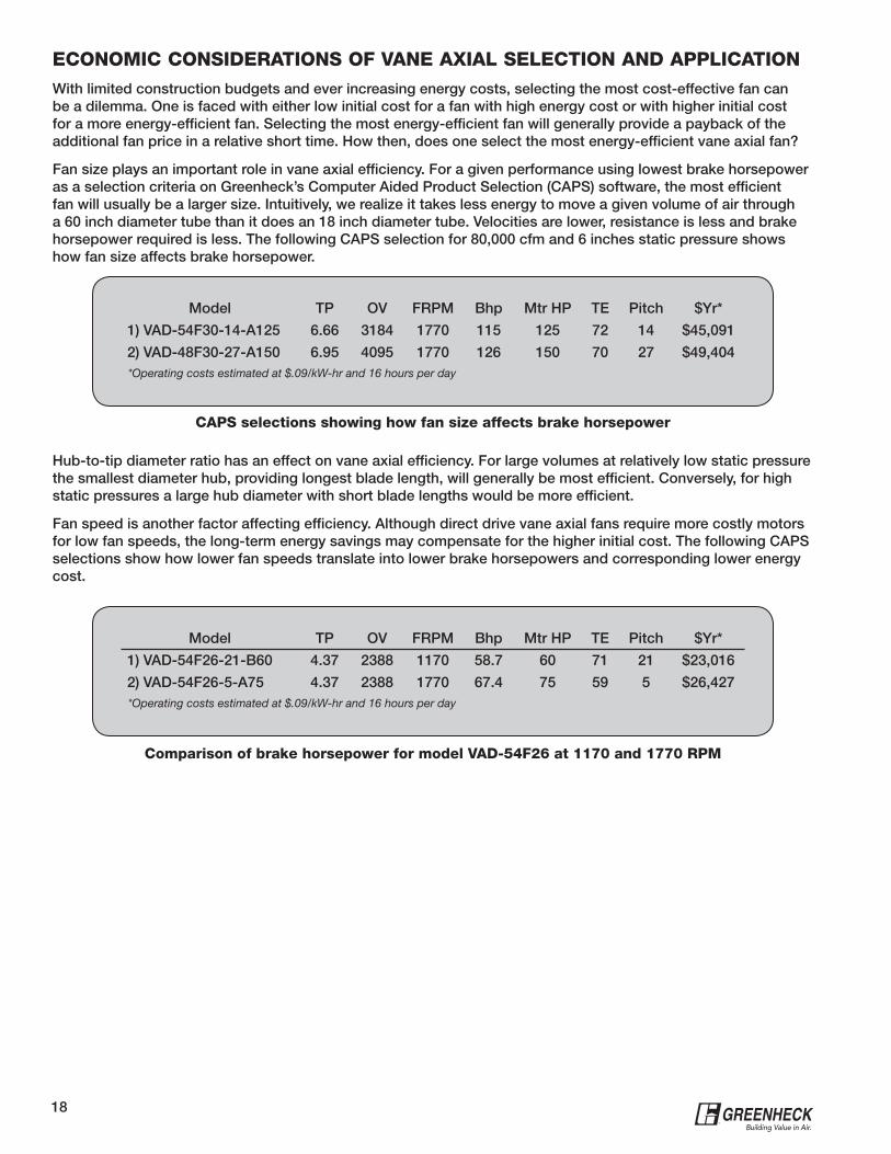
ECONOMIC CONSIDERATIONS OF VANE AXIAL SELECTION AND APPLICATIONWith limited construction budgets and ever increasing energy costs, selecting the most cost-effective fan can be a dilemma. One is faced with either low initial cost for a fan with high energy cost or with higher initial cost for a more energy-efficient fan. Selecting the most energy-efficient fan will generally provide a payback of the additional fan price in a relative short time. How then, does one select the most energy-efficient vane axial fan?
Fan size plays an important role in vane axial efficiency. For a given performance using lowest brake horsepower as a selection criteria on Greenheck’s Computer Aided Product Selection (CAPS) software, the most efficient fan will usually be a larger size. Intuitively, we realize it takes less energy to move a given volume of air through a 60 inch diameter tube than it does an 18 inch diameter tube. Velocities are lower, resistance is less and brake horsepower required is less. The following CAPS selection for 80,000 cfm and 6 inches static pressure shows how fan size affects brake horsepower.
Hub-to-tip diameter ratio has an effect on vane axial efficiency. For large volumes at relatively low static pressure the smallest diameter hub, providing longest blade length, will generally be most efficient. Conversely, for high static pressures a large hub diameter with short blade lengths would be more efficient.
Fan speed is another factor affecting efficiency. Although direct drive vane axial fans require more costly motors for low fan speeds, the long-term energy savings may compensate for the higher initial cost. The following CAPS selections show how lower fan speeds translate into lower brake horsepowers and corresponding lower energy cost.
Model TP OV FRPM Bhp Mtr HP TE Pitch $Yr*
1) VAD-54F30-14-A125 6.66 3184 1770 115 125 72 14 $45,091
2) VAD-48F30-27-A150 6.95 4095 1770 126 150 70 27 $49,404 *Operating costs estimated at $.09/kW-hr and 16 hours per day
CAPS selections showing how fan size affects brake horsepower
Model TP OV FRPM Bhp Mtr HP TE Pitch $Yr*
1) VAD-54F26-21-B60 4.37 2388 1170 58.7 60 71 21 $23,016
2) VAD-54F26-5-A75 4.37 2388 1770 67.4 75 59 5 $26,427 *Operating costs estimated at $.09/kW-hr and 16 hours per day
Comparison of brake horsepower for model VAD-54F26 at 1170 and 1770 RPM
19®
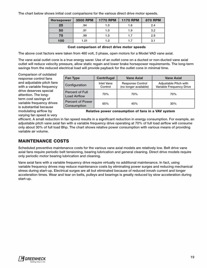
Cost comparison of direct drive motor speeds
The chart below shows initial cost comparisons for the various direct drive motor speeds.
The above cost factors were taken from 460 volt, 3 phase, open motors for a Model VAD vane axial.
The vane axial outlet cone is a true energy saver. Use of an outlet cone on a ducted or non-ducted vane axial outlet will reduce velocity pressure, allow static regain and lower brake horsepower requirements. The long-term savings from the reduced electrical load will provide payback for the outlet cone in minimal time.
Comparison of outdated response control fans and adjustable pitch fans with a variable frequency drive deserves special attention. The long-term cost savings of variable frequency drives is substantial because modulating airflow by varying fan speed is very efficient. A small reduction in fan speed results in a significant reduction in energy consumption. For example, an adjustable pitch vane axial fan with a variable frequency drive operating at 70% of full load airflow will consume only about 30% of full load Bhp. The chart shows relative power consumption with various means of providing variable air volume.
Horsepower 3500 RPM 1770 RPM 1170 RPM 870 RPM
25 .94 1.0 1.6 2.4
50 .91 1.0 1.9 3.2
75 .99 1.0 1.7 2.9
100 1.01 1.0 1.7 3.1
Fan Type Centrifugal Vane Axial Vane Axial
Configuration Inlet Vane Control
Response Control (no longer available)
Adjustable Pitch with Variable Frequency Drive
Percent of Full Load Airflow
70% 70% 70%
Percent of Power Consumption
65% 45% 30%
Relative power consumption of fans in a VAV system
MAINTENANCE COSTSScheduled preventive maintenance costs for the various vane axial models are relatively low. Belt drive vane axial fans require periodic belt tensioning, bearing lubrication and general cleaning. Direct drive models require only periodic motor bearing lubrication and cleaning.
Vane axial fans with a variable frequency drive require virtually no additional maintenance. In fact, using variable frequency drives may reduce maintenance costs by eliminating power surges and reducing mechanical stress during start-up. Electrical surges are all but eliminated because of reduced inrush current and longer acceleration times. Wear and tear on belts, pulleys and bearings is greatly reduced by slow acceleration during start-up.
®
P.O. Box 410 • Schofield, WI 54476-0410 • Phone (715) 359-6171 • greenheck.comCopyright © 2010 Greenheck Fan Corp. • 00.CVI.1025 R3 5-2010 RG
Prepared to SupportGreen Building Efforts
Belt DriveVane axial fans shall be belt driven, Arrangement 9, with the motor attached to the exterior of the fan housing on an adjustable base. Turned, precision ground and polished steel shafts shall be sized so the first critical speed is at least 25% over the maximum operating speed. Bearings shall be grease lubricated, air handling quality ball or roller type selected for a minimum average (L50) life in excess of 200,000 hours at maximum operating speed. Rotor blades and hub shall be heat-treated cast aluminum alloy A356-T6 with blade bases and hub sockets precision machined. Blades shall be attached to the hub with steel studs and self-locking nuts. Hub shall be positively secured with a steel taper lock bushing keyed to the fan shaft. Rotor blade pitch shall be manually adjustable within horsepower limitations. Rotor shall be statically and dynamically balanced to within 0.15 in./sec. peak vibration velocity as measured on the bearings. Fan housing shall be fabricated from heavy-gauge steel with prepunched flanges at both ends. A minimum of seven heavy-gauge straightening vanes shall be welded to the fan housing downstream from the rotor. (For optional Sound Trap construction insert the last paragraph). Vane axial fans shall be model VAB or VABS (select one) as manufactured by Greenheck Fan Corporation of Schofield, Wisconsin, and shall be supplied as shown on the plans and in the fan schedule.
Direct DriveVane axial fans shall be direct driven, Arrangement 4, with the fan rotor secured to the motor shaft. Motors shall be located downstream from the rotor for maximum cooling. Rotor blades and hub shall be heat-treated cast aluminum alloy A356-T6 with blade bases and
hub sockets precision machined. Blades shall be attached to the hub with steel studs and self-locking nuts. Hub shall be positively secured with a steel taper lock bushing keyed to the motor shaft. (Add paragraph for appropriate rotor type here). Rotor shall be statically and dynamically balanced to within 0.08 in./sec. peak vibration velocity as measured on the fan housing. Fan housing shall be fabricated from heavy-gauge steel with prepunched flanges at both ends. A minimum of seven heavy-gauge straightening vanes shall be welded to the fan housing downstream from the rotor. (For optional Sound Trap construction insert paragraph below here). Vane axial fans shall be model VAD or VADS (select one) as manufactured by Greenheck Fan Corporation of Schofield, Wisconsin, and shall be supplied as shown on the plans and in the fan schedule.
Adjustable Pitch RotorBlades shall be manually adjustable within horsepower limitations. A blade tip angle scale shall be machined into the base of the master blade and indexed to the hub. All blades shall be adjustable to align with the master blade pitch setting.
Sound Trap ConstructionWhen specifying optional Sound Trap construction, add the following in the locations noted above: Fan construction shall be double-walled with two inches of sound absorbing material between the walls. The inner wall shall be constructed of perforated steel. Air performance ratings shall be equal to equivalent size fans with a single wall housing.
Specifications
Our CommitmentAs a result of our commitment to continuous improvement, Greenheck reserves the right to change specifications without notice.
Specific Greenheck product warranties are located on greenheck.com within the product area tabs and in the Library under Warranties.