Embed Size (px)
Citation preview
NOVEMBER 2000
APPLICATION AND COMMISSIONING MANUAL
MIT RELAY
EASUN REYROLLE LIMITED
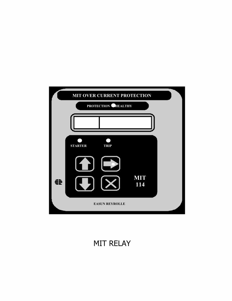
MIT RELAY
MIT OVER CURRENT PROTECTION
PROTECTION HEALTHY
MIT114
STARTER TRIP
EASUN REYROLLE
CONTENTS
PAGE
APPLICATION 4 - 8
INSTALLATION 9 - 16
COMMISSIONING 17- 23
DRAWINGS 24 -31
APPLICATION
1. INTRODUCTION
The type MIT numeric over current protection relay combines the power and flexibilityof microprocessor technology. A wide range of protection elements, characteristics andTRUE RMS measurements are available. Moreover, supervisory components and self-monitoring features give high confidence of
serviceability.
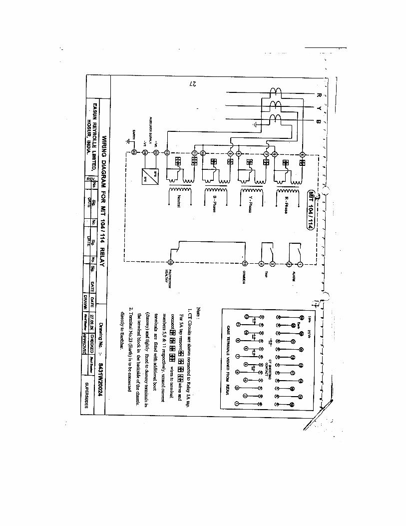
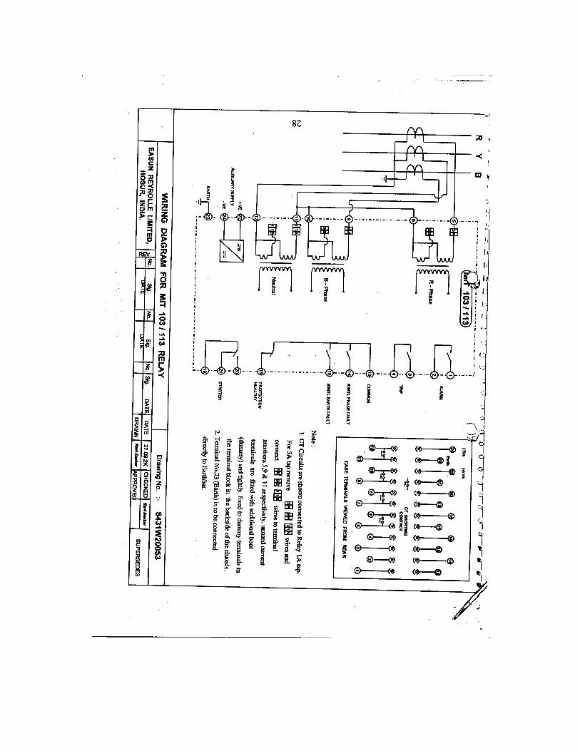
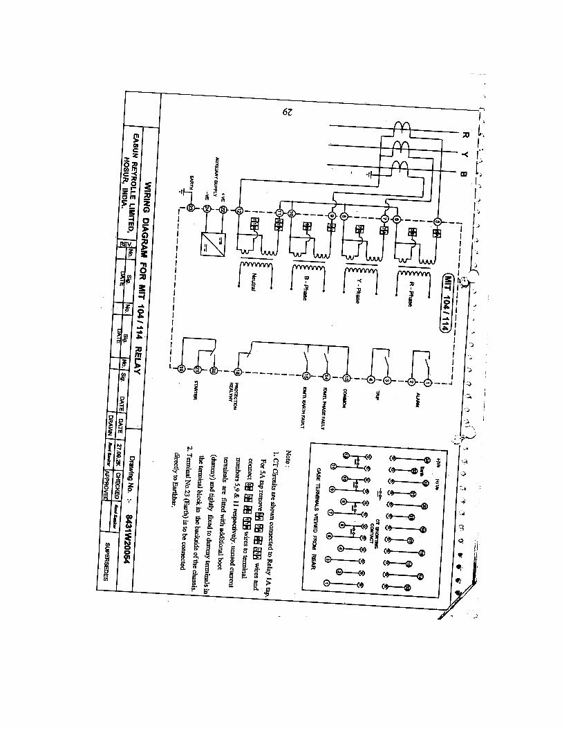
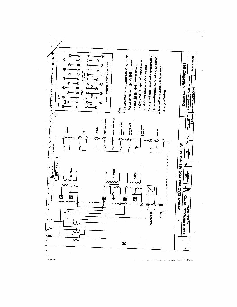
M I T 103 Three Pole Over Current and Earth Fault Relay without HighsetM I T 104 Four Pole Over Current Earth Fault Relay without HighsetM I T 113 Three Pole Over Current Earth Fault Relay with HighsetM I T 114 Four Pole Over Current Earth Fault Relay with Highset
1.1. Multiple Characteristics
MIT relay is suitable for various inverse characteristics and also for definite timelag characteristic, any one of them selectable at site independently for phase and earthfault.
Standard Inverse characteristic - SI 3 theoretical operating time is 3seconds at 10 times current setting at time multiplier setting (TMS) 1.000. Theoreticaloperating time of the Standard Inverse characteristics –SI 1 is 1.3 seconds at 10 timescurrent setting at TMS 1.000.
Very Inverse characteristic - VI curve is suited to networks where there is asignificant reduction in fault current as the distance from the source increases. Theoperating time is shorter for large fault currents and increases at a greater rate as the faultcurrent decreases. This permits the use of the same time multiplier setting for several relays in series.
Extremely Inverse characteristic - EI is very much useful to grade the relay withthe fuse and applications where short duration transient over currents occurs. E.g. motorstarting or reacceleration.
Long time Inverse characteristic - LTI is generally used for Standby Faultprotection for Neutral / Ground Earthing Resistor. The same characteristics can be used toguard against overheating / over loading protection, when it matches with thermalcharacteristics of the motor, generator, transformer or capacitor banks.
Definite Time Lag characteristic - DTL is used for grading the system wheresource impedance determines fault current level and the fault current does not vary to aconsiderable amount down the length of the line.
1.2. DC Transient Free Highset
On transmission lines or transformer feeders where the source impedance is smallcompared with the protection circuit, to reduce the tripping time at high fault level thehighset instantaneous over current element is used in addition to the inverse time overcurrent element. The MIT 113 and MIT 114 relays are provided with highset over currentelements in both phase fault and earth fault. Depending upon the point on wave switchingof the fault and the X/R ratio of the system, the initial current may have DC offset. Thehighset over current unit being instantaneous one, it should not over reach due to initialDC offset current though it may exceed the highset pick-up value. The MIT 113 / 114relays are provided with the DC transient free highset instantaneous elements, which willnot over reach for DC transient condition.
1.3. Reset Time Delay
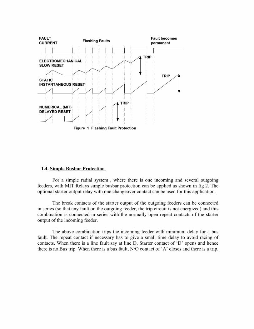
The increasing use of plastic cables, both , conventionally buried types and aerialbundled conductor types have given rise to the number of "pecking" or "flashingintermittent faults on distribution systems. At the fault position, the plastic melts andtemporarily reseals the faulty cable for a short time, after which the insulation falls again.The same phenomenon has occurred in joint boxes where an internal flashovertemporarily reseals.
The behavior of different types of over current relays under flashing faultcondition is compared in Fig.1. The repeating process often caused electromechanical discrelays to "ratchet” up and eventually trip the faulty circuit provided that the reset time ofthe relay was longer than the time between successive flashes. Early electronic IDMTLrelays with instantaneous reset features were not at all effective in dealing with thiscondition and only tripped after the flashing fault had developed into a solid permanentfault.
To overcome this the MIT relay has a reset time setting which can be userprogrammed to be either instantaneous or delayed from 1 to 60 seconds.
On the other hand, on overhead line networks, particularly where reclosers areincorporated in the protected system, instantaneous resetting is desirable to ensure that, onmultiple shot reclosing schemes, correct grading between the source relays and the relaysassociated with the reclosers is maintained.
FAULTCURRENT
ELECTROMECHANICALSLOW RESET
STATICINSTANTANEOUS RESET
NUMERICAL (MIT)DELAYED RESET
TRIP
TRIP
TRIP
Fault becomespermanentFlashing Faults
Figure 1 Flashing Fault Protection
1.4. Simple Busbar Protection
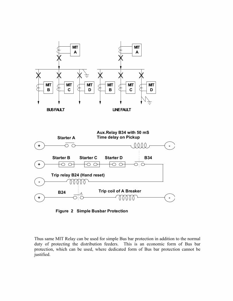
For a simple radial system , where there is one incoming and several outgoingfeeders, with MIT Relays simple busbar protection can be applied as shown in fig 2. Theoptional starter output relay with one changeover contact can be used for this application.
The break contacts of the starter output of the outgoing feeders can be connectedin series (so that any fault on the outgoing feeder, the trip circuit is not energized) and thiscombination is connected in series with the normally open repeat contacts of the starteroutput of the incoming feeder.
The above combination trips the incoming feeder with minimum delay for a busfault. The repeat contact if necessary has to give a small time delay to avoid racing ofcontacts. When there is a line fault say at line D, Starter contact of ‘D’ opens and hencethere is no Bus trip. When there is a bus fault, N/O contact of ‘A’ closes and there is a trip.
MITA
MITC
MITB
MITD
BUS FAULT
MITA
MITC
MITB
MITD
LINE FAULT
Figure 2 Simple Busbar Protection
+
-
Starter B Starter C Starter D
Trip relay B24 (Hand reset)
+ -
Aux.Relay B34 with 50 mSTime delay on Pickup Starter A
+ -Trip coil of A BreakerB24
B34
Thus same MIT Relay can be used for simple Bus bar protection in addition to the normalduty of protecting the distribution feeders. This is an economic form of Bus barprotection, which can be used, where dedicated form of Bus bar protection cannot bejustified.
1.5 Capacitor Bank Protection
The TRUE RMS measurement of the M I T Relay makes it very much suitable forprotection of capacitor banks to guard against the faults in the capacitor and the leadsbetween the circuit breaker and units.
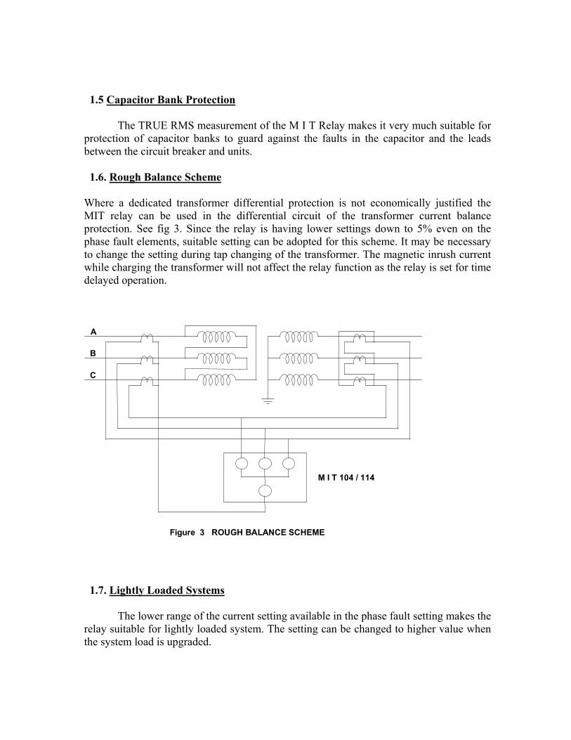
1.6. Rough Balance Scheme
Where a dedicated transformer differential protection is not economically justified theMIT relay can be used in the differential circuit of the transformer current balanceprotection. See fig 3. Since the relay is having lower settings down to 5% even on thephase fault elements, suitable setting can be adopted for this scheme. It may be necessaryto change the setting during tap changing of the transformer. The magnetic inrush currentwhile charging the transformer will not affect the relay function as the relay is set for timedelayed operation.
Figure 3 ROUGH BALANCE SCHEME
A
B
C
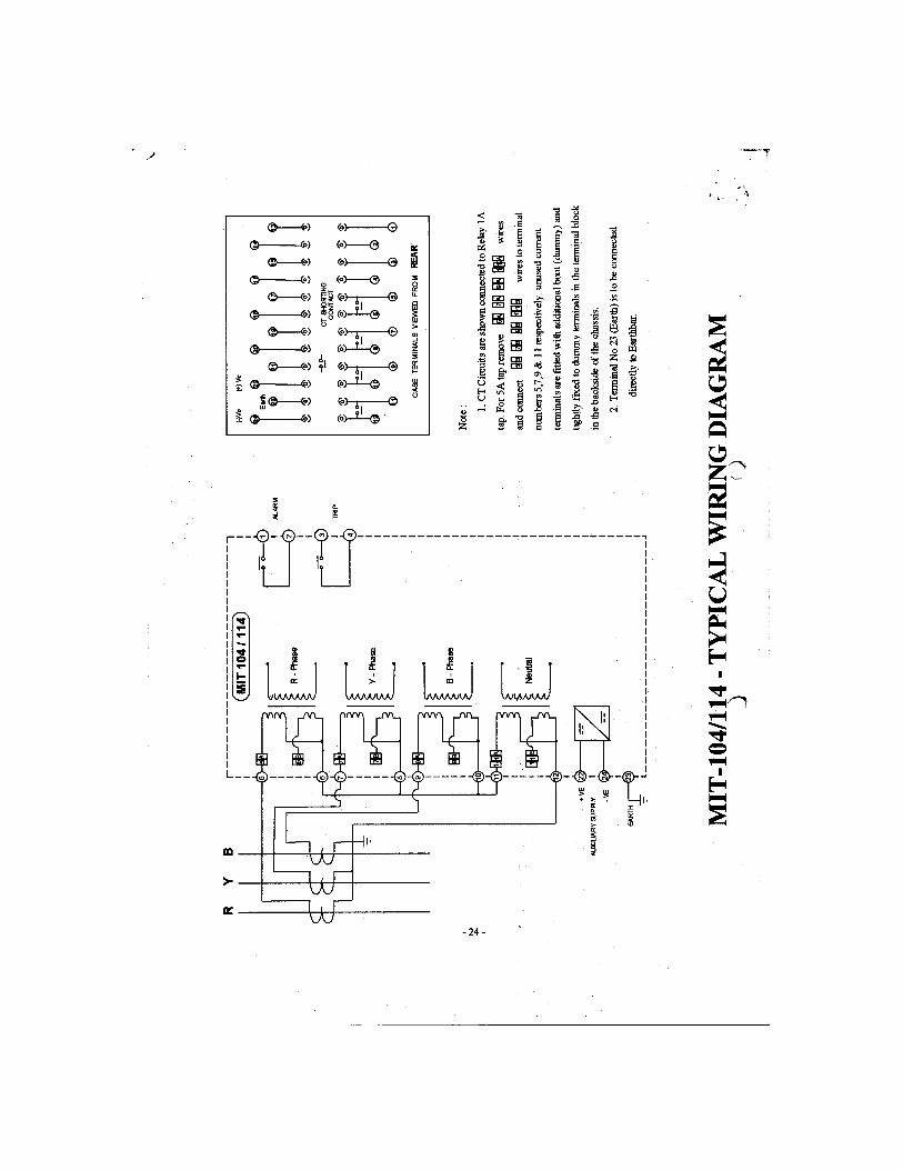
M I T 104 / 114
1.7. Lightly Loaded Systems
The lower range of the current setting available in the phase fault setting makes therelay suitable for lightly loaded system. The setting can be changed to higher value whenthe system load is upgraded.
INSTALLATION1.1 . Unpacking
On receipt, remove the relay from the carton box in which it was received andinspect it for obvious damage. It is recommended that the relay is not removed from therelay case. To prevent the possible ingress of dirt, the sealed polythene bag should not beopened until the relay is to be used.
If damage has been sustained, please inform Easun Reyrolle Ltd., for necessaryaction.
1.2 . Storage
When the relay is not required for immediate use, it should be returned to itsoriginal carton and stored in a clean dry place.
1.3 . Handling
The relay’s electronic circuits are protected from damage by static discharge when therelay is housed in its case. When relay is withdrawn from the case, static handlingprocedures should be observed:
• Before removing the relay from its case the operator must first ensure that he is atthe same potential as the relay, by touching the case.
• The relay must not be handled by any of the relay terminals at the rear of thechassis.
• Ensure that anyone else handling the relay is at the same potential. As there are no user serviceable parts and adjustable user settings inside the relay, thereshould be no requirement to remove any modules from the chassis.
If any modules are removed or tampered with, then the guarantee will beinvalidated.
1.4 Mounting
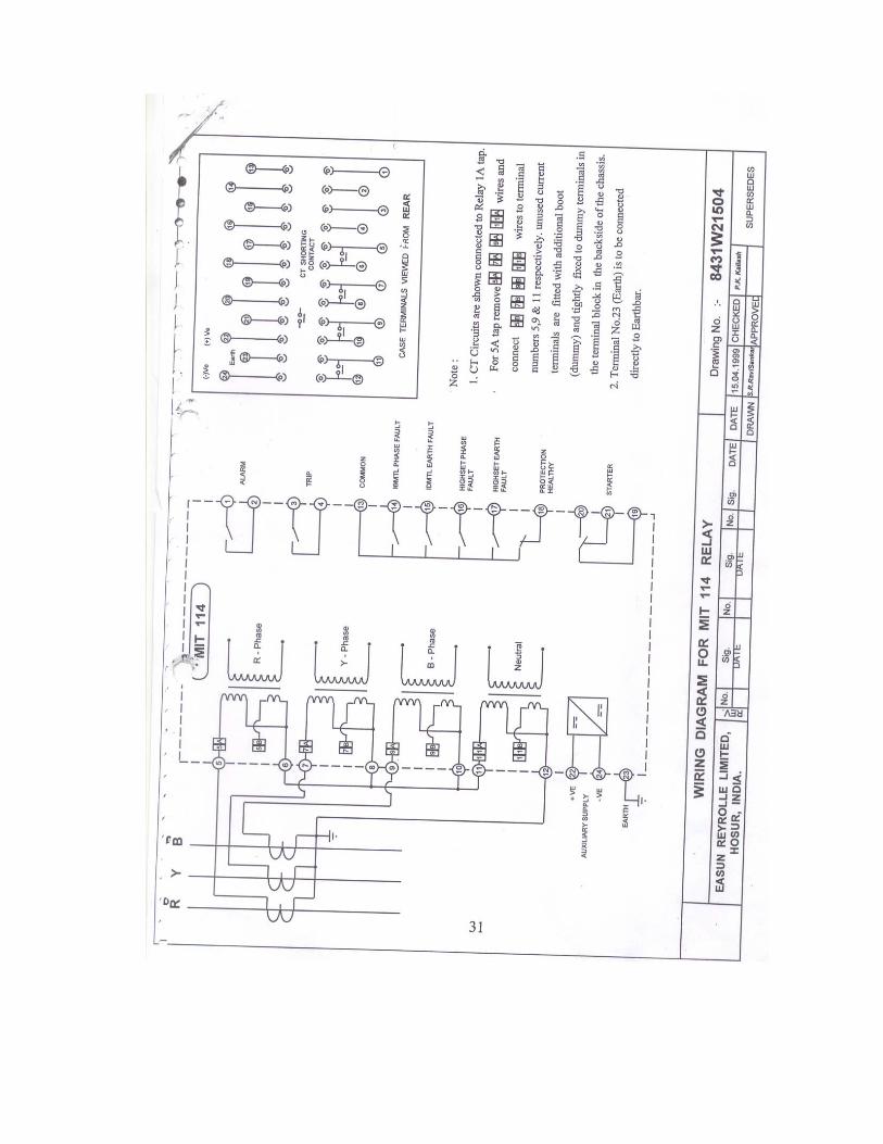
Mount the relay using 2 nos mounting straps and 1no earth strap. Ensure that an earthwire is connected to the earth strap from the earth terminal 23. Terminal 23 should bedirectly connected to the system ground. Only settings or trip details can be accessed via the pushbuttons when the cover is fitted.To change the settings the front cover has to be removed. Sealing arrangement isprovided in one of the four knurling screws fitted on the cover. Sealing can be done usinga sealing wire. Thus mechanical interlock is provided to avoid unauthorized settingchange.
2. EQUIPMENT
2.1 Current tap Selection
MIT relays are suitable for 1A or 5A application. However the relays are internallywired for either 1A or 5A as per the customer requirement. Internal wirings are to bechanged (Faston crimp connections) for changing the relay rating from one to other.
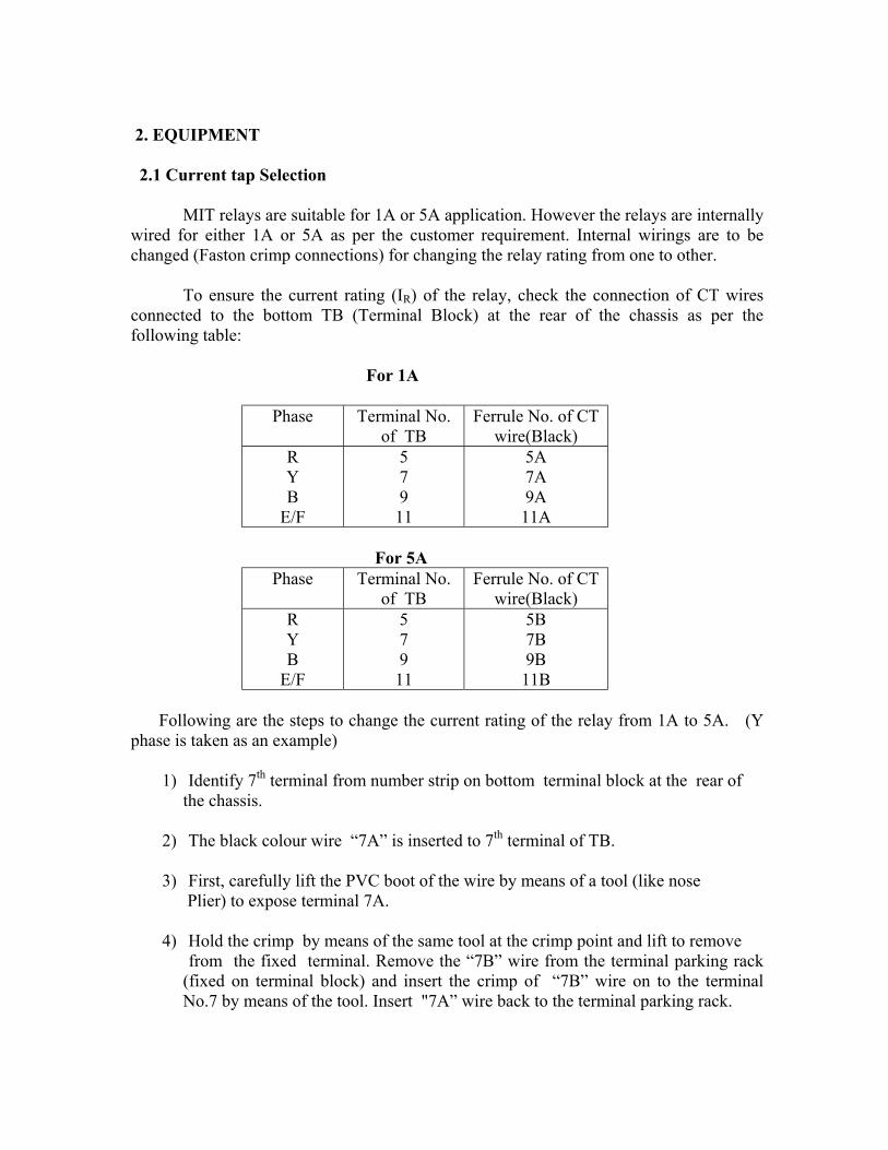
To ensure the current rating (IR) of the relay, check the connection of CT wiresconnected to the bottom TB (Terminal Block) at the rear of the chassis as per thefollowing table:
For 1A
Phase Terminal No.of TB
Ferrule No. of CTwire(Black)
RYB
E/F
57911
5A7A9A11A
For 5A Phase Terminal No.
of TBFerrule No. of CT
wire(Black)RYB
E/F
57911
5B7B9B11B
Following are the steps to change the current rating of the relay from 1A to 5A. (Yphase is taken as an example)
1) Identify 7th terminal from number strip on bottom terminal block at the rear of the chassis.
2) The black colour wire “7A” is inserted to 7th terminal of TB.
3) First, carefully lift the PVC boot of the wire by means of a tool (like nose Plier) to expose terminal 7A.
4) Hold the crimp by means of the same tool at the crimp point and lift to remove from the fixed terminal. Remove the “7B” wire from the terminal parking rack
(fixed on terminal block) and insert the crimp of “7B” wire on to the terminalNo.7 by means of the tool. Insert "7A” wire back to the terminal parking rack.
5) Ensure proper insertion of “7B” wire by pulling the wire by hand and the wire Should not come off the terminal.
6) Push the boot of “7B” wire to completely cover the crimp.
7) Follow the same routing for other phases also.
Same procedure in reverse is to be followed to change from 5A to 1A usingappropriate wire numbers
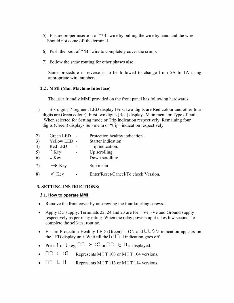
2.2 . MMI (Man Machine Interface)
The user friendly MMI provided on the front panel has following hardwares.
1) Six digits, 7 segment LED display (First two digits are Red colour and other fourdigits are Green colour). First two digits (Red) displays Main menu or Type of fault
When selected for Setting mode or Trip indication respectively. Remaining four digits (Green) displays Sub menu or “trip” indication respectively.
2) Green LED - Protection healthy indication.3) Yellow LED - Starter indication.4) Red LED - Trip indication.5) ↑ Key - Up scrolling6) ↓ Key - Down scrolling
7) → Key - Sub menu
8) × Key - Enter/Reset/Cancel/To check Version.
3. SETTING INSTRUCTIONS:
3.1. How to operate MMI
• Remove the front cover by unscrewing the four knurling screws.
• Apply DC supply. Terminals 22, 24 and 23 are for +Ve, -Ve and Ground supplyrespectively as per relay rating. When the relay powers up it takes few seconds tocomplete the self-test routine.
• Ensure Protection Healthy LED (Green) is ON and indication appears onthe LED display unit. Wait till the indication goes off.
• Press ↑ or ↓ key, or is displayed.
• Represents M I T 103 or M I T 104 versions.
• Represents M I T 113 or M I T 114 versions.
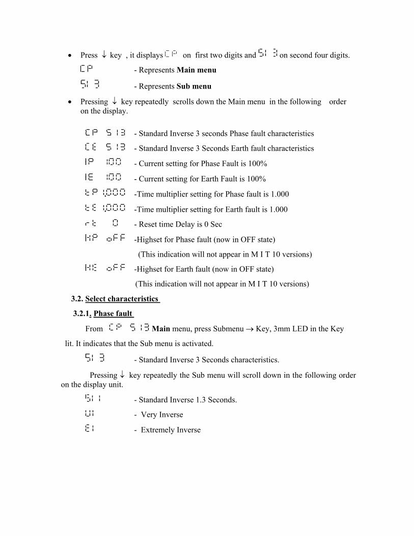
• Press ↓ key , it displays on first two digits and on second four digits.
- Represents Main menu
- Represents Sub menu
• Pressing ↓ key repeatedly scrolls down the Main menu in the following orderon the display.
- Standard Inverse 3 seconds Phase fault characteristics
- Standard Inverse 3 Seconds Earth fault characteristics
- Current setting for Phase Fault is 100%
- Current setting for Earth Fault is 100%
-Time multiplier setting for Phase fault is 1.000
-Time multiplier setting for Earth fault is 1.000
- Reset time Delay is 0 Sec
-Highset for Phase fault (now in OFF state)
(This indication will not appear in M I T 10 versions)
-Highset for Earth fault (now in OFF state)
(This indication will not appear in M I T 10 versions)
3.2. Select characteristics
3.2.1. Phase fault
From Main menu, press Submenu → Key, 3mm LED in the Key
lit. It indicates that the Sub menu is activated.
- Standard Inverse 3 Seconds characteristics.
Pressing ↓ key repeatedly the Sub menu will scroll down in the following orderon the display unit.
- Standard Inverse 1.3 Seconds.
- Very Inverse
- Extremely Inverse
- Long Time Inverse
- Definite Time Lag
By pressing ↑ or ↓ key choose the desired characteristic and press →key. NowSubmenu LED goes OFF and the Main menu appears on the LED display.
3.2.2. Earth fault
To select Earth fault characteristics, get from Main menu, followthe same procedure mentioned above for Phase Fault Characteristics.
3.3. Current settings
Setting range: 5% to 250% in steps of 5% (Phase and Earth fault)
3.3.1. Phase fault
From Main menu, press ↓ key repeatedly to get mainmenu (for Phase fault current setting). Press → key (Submenu LED On) to get the Submenu. Pressing the ↑ or ↓ key, changes the current setting in 1% increments. Uponselecting the desired setting, once again press the → key (Sub menu LED goes OFF) toreturn to the main menu.
3.3.2. Earth fault
Select Earth fault Current setting, from Main menu, follow the sameprocedure mentioned for Phase fault.
3.4. Time Multiplier Setting (For IDMTL char.)
Setting range: 0.025 Seconds to 1.00 Seconds in steps of 0.001 Seconds (Phaseand Earth fault)
3.4.1. Phase fault
From Main menu, press ↓ key repeatedly to get mainmenu (for Phase fault). Press → key (Submenu LED On) to get Submenu. Pressing ↑ or↓ key, changes time multiplier setting by 0.001 increments. Upon selecting the desiredsetting, once again press the → key (Sub menu LED goes OFF) to return to the mainmenu.
3.4.2. Earth fault
Select Earth fault Time Multiplier, from Main menu, and follow thesame procedure mentioned for Phase fault.

3.5. Definite Time Lag (For DTL char.)
Setting range: 0 Sec to 20 Seconds in steps of 0.01 Sec. (Phase and Earth fault)
3.5.1. Phase fault
From Main menu, press → key to get Sub menu and select .Once again press the → key (Sub menu LED goes OFF) to get back the main menu.
Press ↓ key repeatedly to get main menu (for Phase fault).
Press → key (Submenu LED On) to get Submenu.
Pressing ↑ or ↓ key, changes TIME setting by 0.01 sec increments.
After selecting the desired setting, once again press the → key (Sub menu LED goes OFF)to get back the main menu.
3.5.2. Earth fault
Select Earth fault Time Multiplier, from Main menu,, follow thesame procedure mentioned for Phase fault.
3.6. Reset time
Setting range: 0 Second to 60 seconds in steps of 1 Second.
(Reset time is common for both Phase and Earth fault)
From Main menu, press ↓ key repeatedly to get Mainmenu. Press → key (Submenu LED On) to get Submenu. Pressing the ↑ or ↓ key,changes reset time delay by 1sec increments. After selecting the desired setting, onceagain press the → key (Sub menu LED goes OFF) to get back the main menu.
3.7. Highset (For MIT 113 or MIT 114 versions only)
Setting range: 50% to 3000% in steps of 50% (Phase and Earth fault).
3.7.1. Phase fault
From Main menu, Press → key (Submenu LED On) to get Submenu.Pressing the ↑ or ↓ key, changes highset value by 50% increments. After selecting thedesired setting, once again press the → key (Sub menu LED goes OFF) to return to themain menu.
3.7.2. Earth fault
To get Earth fault highset, from Main menu, follow the sameprocedure mentioned for Phase fault.

3.8 Acceptance of Settings
For the relay to accept the above setting changes press ×push switch once, now thedisplay goes off and the settings are updated. By pressing any switch again
or indication will appear.
Ensure all the chosen settings are as per requirements.
To change existing settings, choose corresponding Main menu and select the Sub menu(ensure LED ON), using ↑ or ↓ key change the previous setting and once again press the
Sub menu switch → (LED OFF). Finally press Enter × switch once.
ENSURE ‘ X ’ KEY IS PRESSED TO ACCEPT THE
SETTING CHANGES
4. TO CHECK THE RELAY VERSION
Press X push switch four times quickly. Example of relay Version display is asfollows:
- Represents M I T 114 relay, version 1.
To get back the main menu presses ↑ or ↓ key.
5. TRIP INDICATION AND RESETTING OF TRIP INDICATION
When the relay operates, RED LED indicates tripping. To find the 'Type of fault', pressany arrow key.
Indicates Earth fault ( Earth pole tripped )
Further press any arrow key , the following trip information's will come depending upontype of fault.
Indicates R - pole is tripped
Indicates Y - pole is tripped
Indicates B - pole is tripped
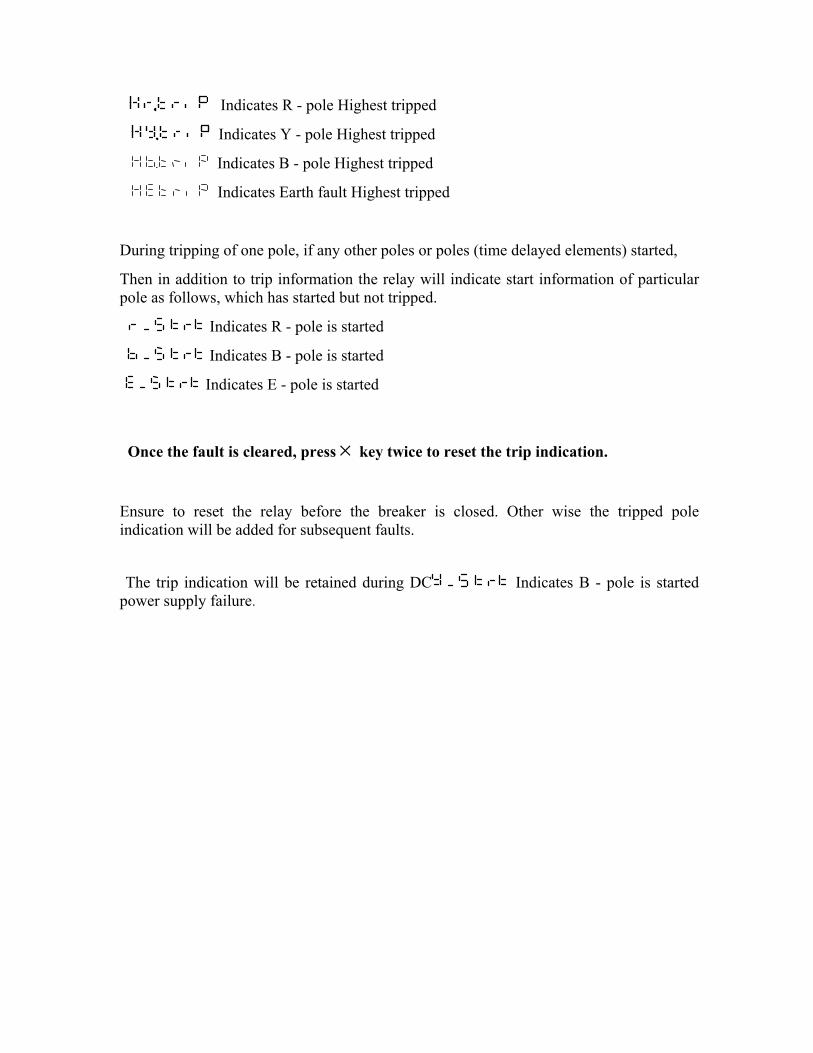
Indicates R - pole Highest tripped
Indicates Y - pole Highest tripped
Indicates B - pole Highest tripped
Indicates Earth fault Highest tripped
During tripping of one pole, if any other poles or poles (time delayed elements) started,
Then in addition to trip information the relay will indicate start information of particularpole as follows, which has started but not tripped.
Indicates R - pole is started
Indicates B - pole is started
Indicates E - pole is started
Once the fault is cleared, press × key twice to reset the trip indication.
Ensure to reset the relay before the breaker is closed. Other wise the tripped poleindication will be added for subsequent faults.
The trip indication will be retained during DC Indicates B - pole is startedpower supply failure.
COMMISSIONING 1.1. Required Test Equipments
• 500V insulation test sets.• Variable secondary injection current source rated 10A or greater.• Time interval meter • Primary injection equipment • A DC supply with a nominal voltage within the working range of the relays DC
auxiliary supply ratings
2. Inspection
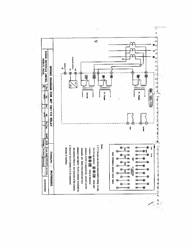
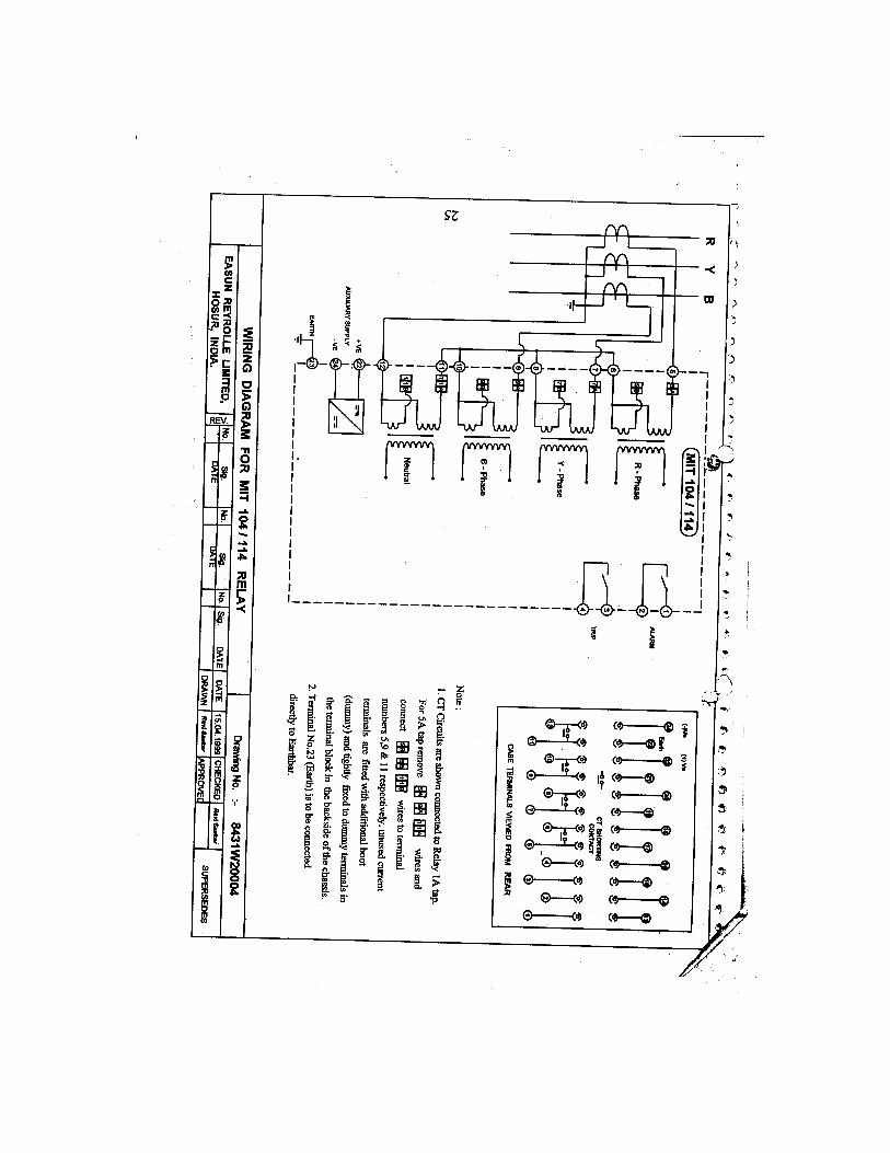
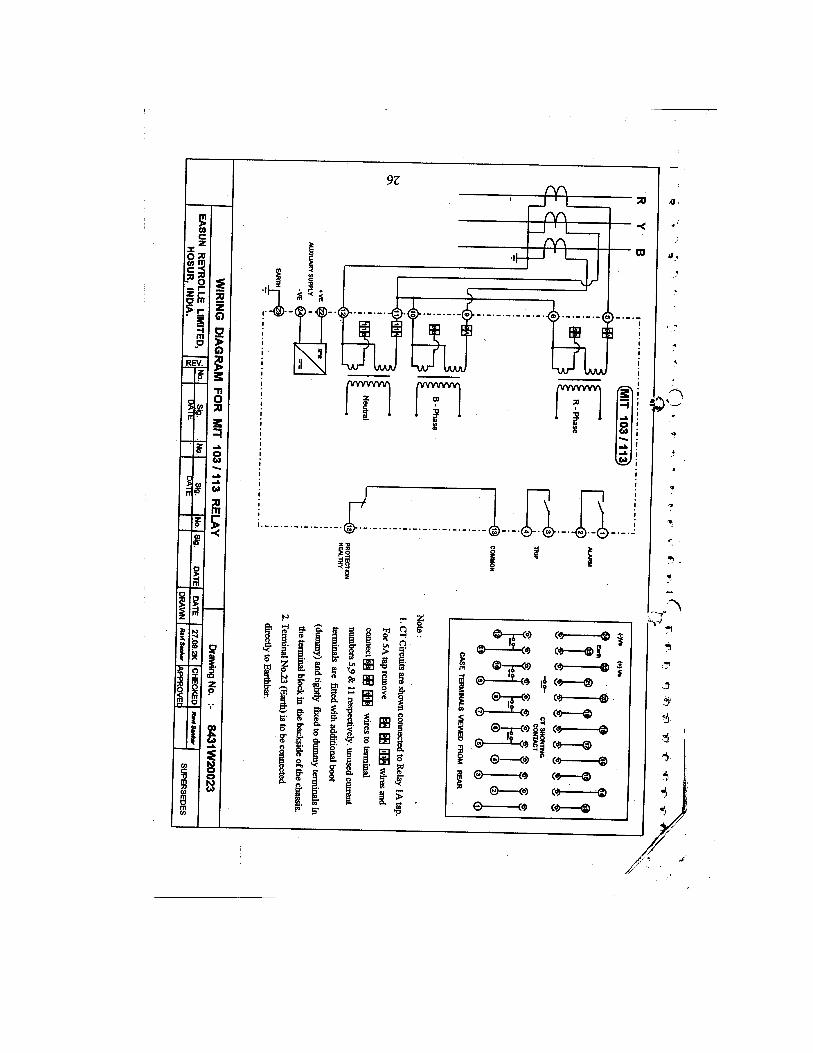
Ensure that all connections are tight and in accordance with the relay wiringdiagram and the scheme diagram. Check if the relay is correctly programmed and therelay is fully inserted into the case.
3. Applying settings
The relay settings for the particular application should be applied before anysecondary testing is started. 4 . Precautions
Before testing commences, the equipment should be isolated from the currenttransformers and the CTs to be short-circuited, in line with the local site procedures. Thetripping and alarm circuits should also be isolated, where practical. Also, ensure that triplinks are removed.Ensure that correct DC auxiliary voltage and polarity is applied. See the relevant schemediagrams for the relay connections.
5. TESTS
5.1. Insulation
Connect together all relay CT terminals and measure the insulation resistancebetween these terminals and all the other relay terminals connected together to earth.
Connect together the terminals of the DC auxiliary supply (only +ve and -ve) andmeasure the insulation resistance between these terminals and all other terminalsconnected together to earth.Connect together all the output relay terminals and measure the insulation resistancebetween these terminals and all other terminals connected together to earth. A minimumvalue of 2. 5 to 3 meg ohms can be considered as satisfactory value.
5.2. Secondary injection
Select the relay configuration and settings for the application. Note that the MITrelay can be connected either as 1A or 5A-rated device. The user should check this beforecommencing secondary test. Please refer Sec. 2.1. in installation
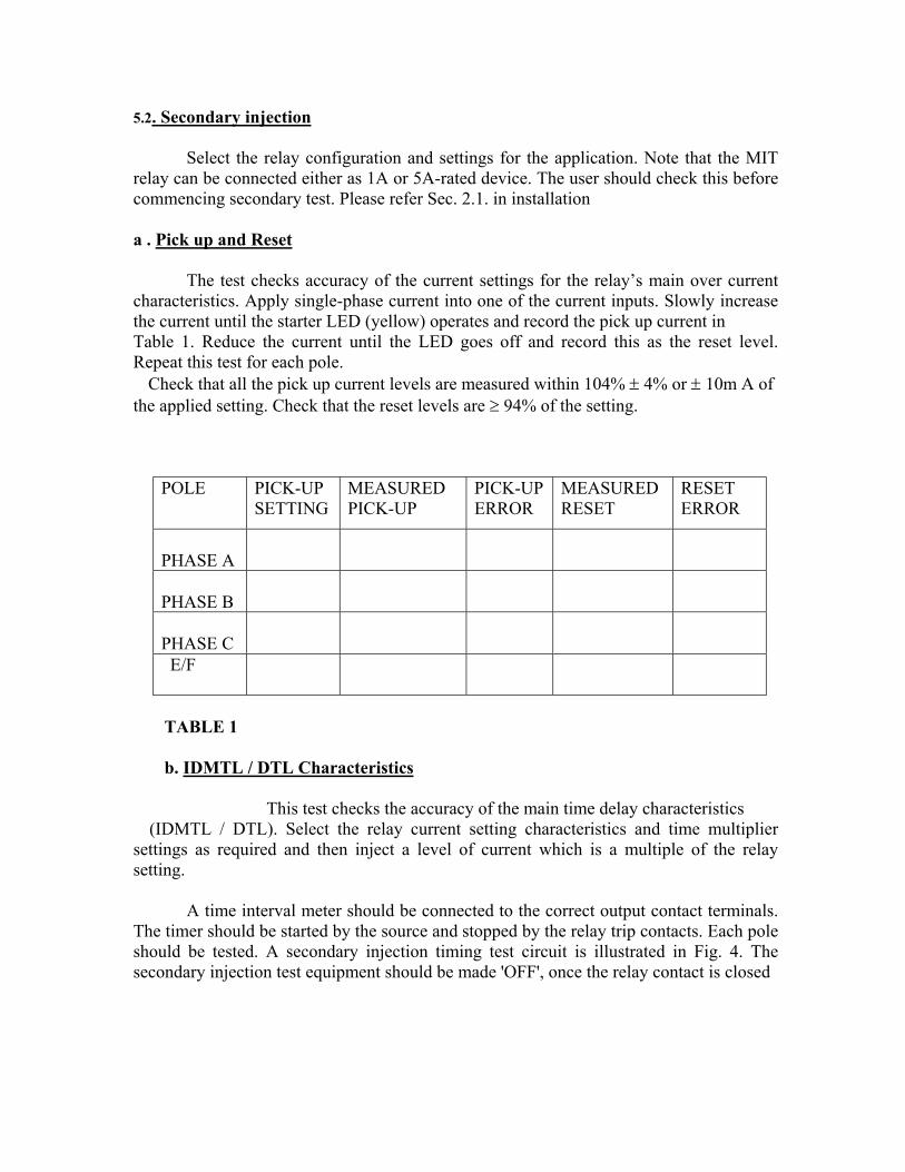
a . Pick up and Reset
The test checks accuracy of the current settings for the relay’s main over currentcharacteristics. Apply single-phase current into one of the current inputs. Slowly increasethe current until the starter LED (yellow) operates and record the pick up current in Table 1. Reduce the current until the LED goes off and record this as the reset level.Repeat this test for each pole. Check that all the pick up current levels are measured within 104% ± 4% or ± 10m A ofthe applied setting. Check that the reset levels are ≥ 94% of the setting.
POLE PICK-UPSETTING
MEASUREDPICK-UP
PICK-UPERROR
MEASUREDRESET
RESETERROR
PHASE A
PHASE B
PHASE C E/F
TABLE 1 b. IDMTL / DTL Characteristics
This test checks the accuracy of the main time delay characteristics (IDMTL / DTL). Select the relay current setting characteristics and time multipliersettings as required and then inject a level of current which is a multiple of the relaysetting.
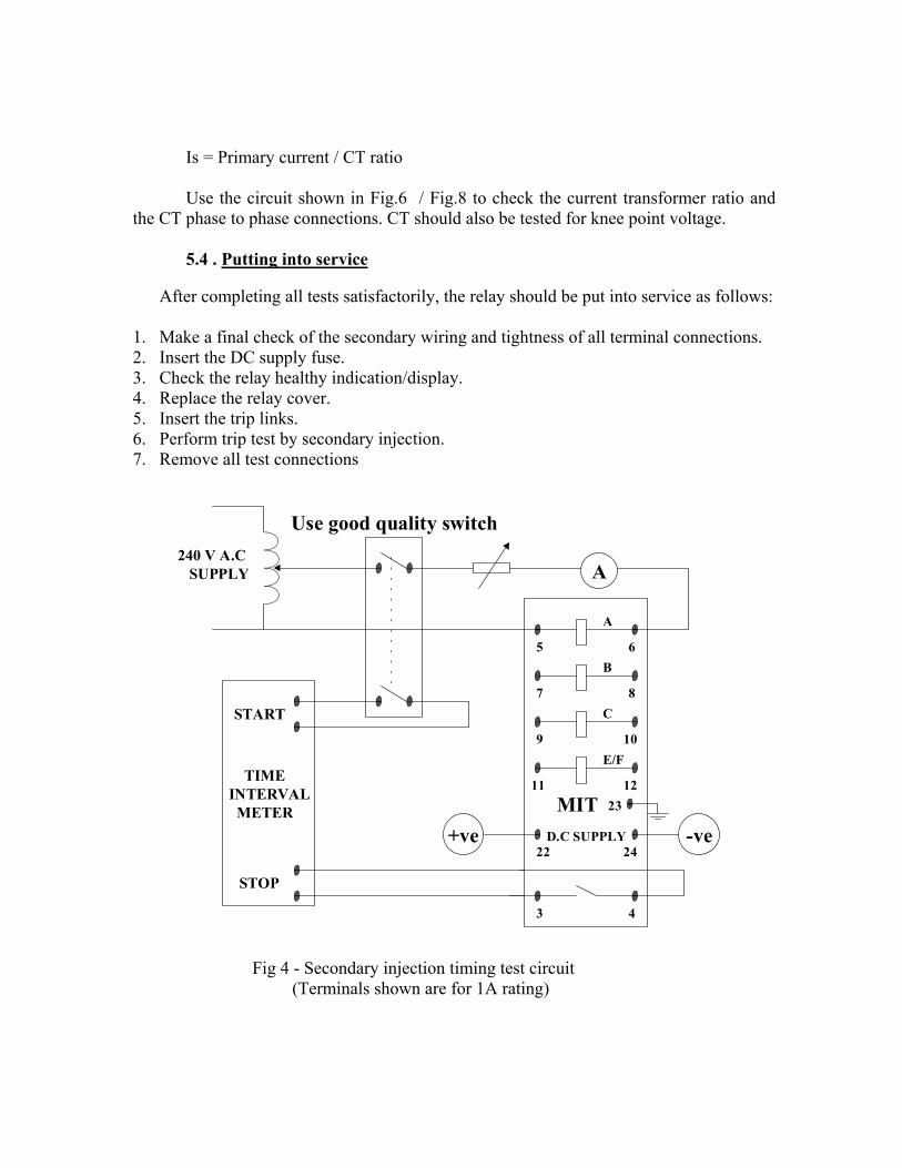
A time interval meter should be connected to the correct output contact terminals.The timer should be started by the source and stopped by the relay trip contacts. Each poleshould be tested. A secondary injection timing test circuit is illustrated in Fig. 4. Thesecondary injection test equipment should be made 'OFF', once the relay contact is closed
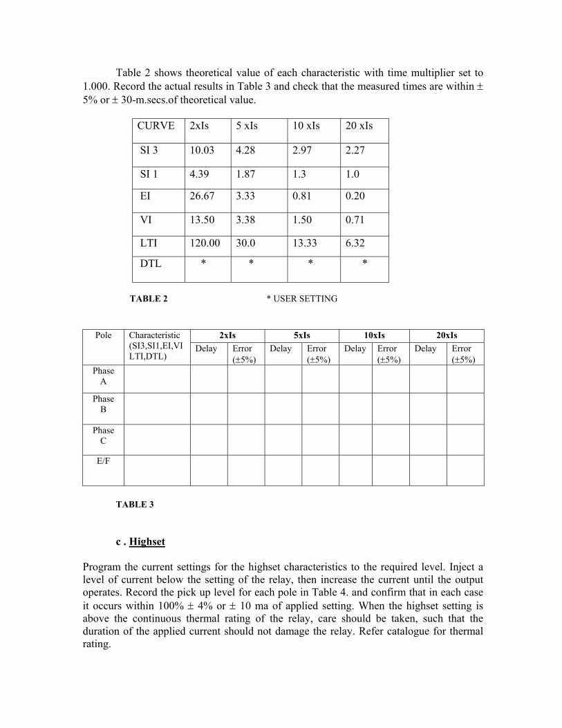
Table 2 shows theoretical value of each characteristic with time multiplier set to1.000. Record the actual results in Table 3 and check that the measured times are within ±5% or ± 30-m.secs.of theoretical value.
CURVE 2xIs 5 xIs 10 xIs 20 xIs
SI 3 10.03 4.28 2.97 2.27
SI 1 4.39 1.87 1.3 1.0
EI 26.67 3.33 0.81 0.20
VI 13.50 3.38 1.50 0.71
LTI 120.00 30.0 13.33 6.32
DTL * * * *
TABLE 2 * USER SETTING
2xIs 5xIs 10xIs 20xIsPole Characteristic(SI3,SI1,EI,VILTI,DTL)
Delay Error(±5%)
Delay Error(±5%)
Delay Error(±5%)
Delay Error(±5%)
PhaseA
PhaseB
PhaseC
E/F
TABLE 3
c . Highset
Program the current settings for the highset characteristics to the required level. Inject alevel of current below the setting of the relay, then increase the current until the outputoperates. Record the pick up level for each pole in Table 4. and confirm that in each caseit occurs within 100% ± 4% or ± 10 ma of applied setting. When the highset setting isabove the continuous thermal rating of the relay, care should be taken, such that theduration of the applied current should not damage the relay. Refer catalogue for thermalrating.
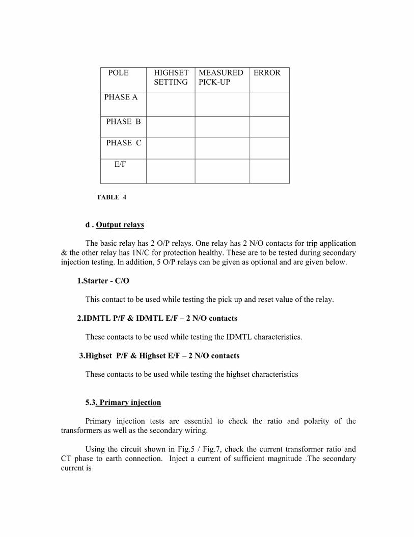
POLE HIGHSET SETTING
MEASUREDPICK-UP
ERROR
PHASE A
PHASE B
PHASE C
E/F
TABLE 4
d . Output relays
The basic relay has 2 O/P relays. One relay has 2 N/O contacts for trip application& the other relay has 1N/C for protection healthy. These are to be tested during secondaryinjection testing. In addition, 5 O/P relays can be given as optional and are given below.
1.Starter - C/O
This contact to be used while testing the pick up and reset value of the relay.
2.IDMTL P/F & IDMTL E/F – 2 N/O contacts
These contacts to be used while testing the IDMTL characteristics.
3.Highset P/F & Highset E/F – 2 N/O contacts
These contacts to be used while testing the highset characteristics
5.3. Primary injection
Primary injection tests are essential to check the ratio and polarity of thetransformers as well as the secondary wiring.
Using the circuit shown in Fig.5 / Fig.7, check the current transformer ratio andCT phase to earth connection. Inject a current of sufficient magnitude .The secondarycurrent is
Is = Primary current / CT ratio
Use the circuit shown in Fig.6 / Fig.8 to check the current transformer ratio andthe CT phase to phase connections. CT should also be tested for knee point voltage.
5.4 . Putting into service
After completing all tests satisfactorily, the relay should be put into service as follows:
1. Make a final check of the secondary wiring and tightness of all terminal connections.2. Insert the DC supply fuse.3. Check the relay healthy indication/display.4. Replace the relay cover.5. Insert the trip links.6. Perform trip test by secondary injection.7. Remove all test connections
Fig 4 - Secondary injection timing test circuit (Terminals shown are for 1A rating)
A
TIMEINTERVAL METER
START
STOP
240 V A.C SUPPLY
+ve -veD.C SUPPLY
A
B
C
E/F
MIT
5 6
7 8
9 10
11 12
22 24
3 4
23
Use good quality switch
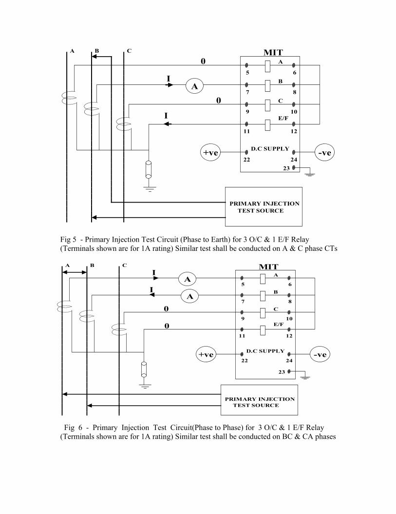
Fig 5 - Primary Injection Test Circuit (Phase to Earth) for 3 O/C & 1 E/F Relay (Terminals shown are for 1A rating) Similar test shall be conducted on A & C phase CTs
Fig 6 - Primary Injection Test Circuit(Phase to Phase) for 3 O/C & 1 E/F Relay (Terminals shown are for 1A rating) Similar test shall be conducted on BC & CA phases
+ve -veD.C SUPPLY
A
B
C
E/F
A
PRIMARY INJECTION TEST SOURCE
MITA
B C
5 6
7 8
9 10
11 12
22 2423
0
0
I
I
+ve -veD.C SUPPLY
A
B
C
E/F
A
PRIMARY INJECTION TEST SOURCE
MITA
B C
A5 6
7 8
9 10
22 24
11 12
23
I
I
0
0
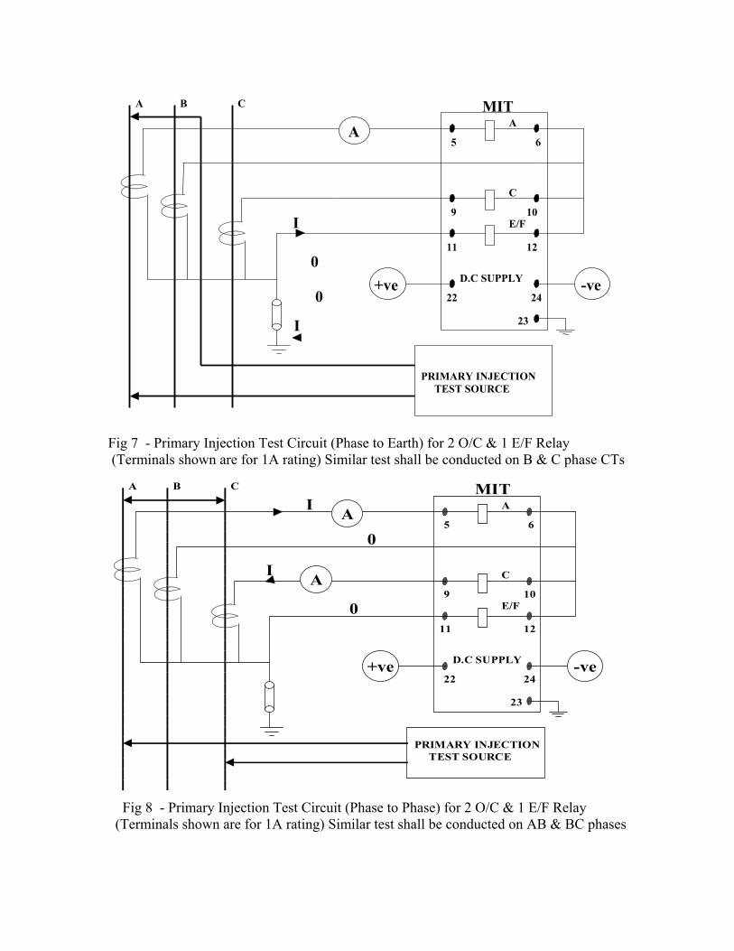
Fig 7 - Primary Injection Test Circuit (Phase to Earth) for 2 O/C & 1 E/F Relay (Terminals shown are for 1A rating) Similar test shall be conducted on B & C phase CTs
Fig 8 - Primary Injection Test Circuit (Phase to Phase) for 2 O/C & 1 E/F Relay (Terminals shown are for 1A rating) Similar test shall be conducted on AB & BC phases
+ve -veD.C SUPPLY
A
C
E/F
PRIMARY INJECTION TEST SOURCE
MITA
B C
A
22 24
5 6
9 10
11 12
23
I
I
0
0
+ve -veD.C SUPPLY
A
C
E/F
PRIMARY INJECTION TEST SOURCE
MITA
B C
A
A
22 24
5 6
9 10
11 12
23
I
I
0
0

![Untitled-1 [] · Run Capacitor Stator Winding Relay Rotary Switch Rotor Start capacitor Main or Run Windin Stator Winding Main Winding Start capacitor Rotor](https://img.pdfslide.us/doc/110x75/5fc791720420d159865384b0/untitled-1-run-capacitor-stator-winding-relay-rotary-switch-rotor-start-capacitor.jpg)