Embed Size (px)
Citation preview

Reyrolle
Protection
Devices
Answers for energy
7SG23 - MSCDN Capacitor Bank Protection

7SG23 - MSCDN Capacitor Bank Protection
C1
C2
R2R1
M P1
M P2a
M P2b
Back up O /C
Capacitor banks require a varied range of protection devices to monitor the system. Traditional solutions use many dif-ferent relay types most of which were designed for other purposes. The MSCDN-MP has a unique range of purpose designed functions to cover all of the protection require-ments in three multi-functional boxes: MSCDN-MP1 MSCDN-MP2a MSCDN-MP2b
MSCDN-MP* Analogue Inputs
Current & Voltage signals are sampled at 32 samples per cycle which provides accurate measurements up to 750Hz (15th Harmonic). Output Relays
All the output relays are capable of handling circuit breaker tripping duty. All relays are fully user configurable and can be programmed to operate from any or all of the control functions. In normal operation output relays remain ener-gised for a minimum of 100ms and a maximum dependent on the energising condition duration. However outputs can be programmed as latching relays. Status Inputs
The Status Inputs can be programmed to be used for any function, a timer is associated with each input and a pickup time setting may be applied. Each input can also be logically inverted and each input may be mapped to the fascia LED’s or any output relay contact. Status inputs can be used to give a trip circuit supervision scheme. Fascia LED’s
There are 32 user programmable LED flag indicators on the front fascia of each relay. The user can customise which LED is used for which purpose as well as being able to program each LED as being latching or self-resetting.
Self Monitoring
The relay incorporates a number of self-monitoring features. Each of these features can initiate a controlled reset recov-ery sequence, which can be used to generate an alarm out-put. In addition, the Protection Healthy LED will give visual indication. A watchdog timer continuously monitors the microproces-sor. The voltage rails are also continuously supervised and the microprocessor is reset if any of the rails falls outside of their working ranges. Any failure is detected in sufficient time so that the micro can be shut down in a safe and con-trolled manner.
Description
RMS capacitor bank currents (primary, secondary and relay) RMS overall differential currents (secondary and relay) RMS capacitor spill currents (primary, secondary and relays) RMS Phase unbalance currents (primary, secondary and relay) System voltage (Primary, secondary) Digital input status Output relay
Time & Date
Application
Monitoring Functions
Function Overview
The MSCDN range represents an integration of the protec-tion elements required to provide a single box Main 1 and Main 2 protection of EHV capacitor banks. Applications covered include overall differential protection, capacitor unbalance protection additional phase unbalance backup protection, true RMS phase by phase resistor thermal overload protection, resistor open circuit protection, true RMS phase-by-phase reactor thermal overload protection, backup overcurrent and earth faults protection and over-voltage protection. Fig 1. Typical application for the MSCDN range
Siemens Protection Devices Limited 2
Siemens Protection Devices Limited 3
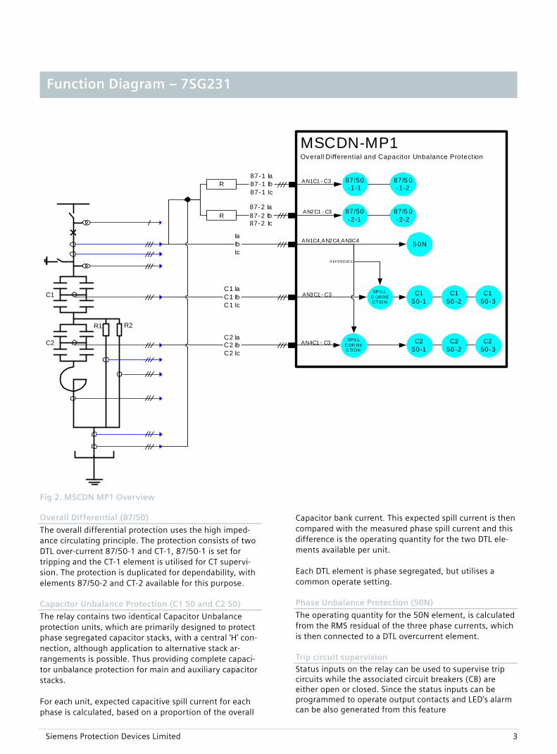
Function Diagram – 7SG231
MSCDN-MP1Overall Differential and Capacitor Unbalance Protection
IaIbIc
C1 IaC1 IbC1 Ic
C2 IaC2 IbC2 Ic
SP ILLC ORRECTIO N
SPILLCOR RECTION
C1
C2
R2R1
C150-1
C150 -2
C250-1
C250 -2
87-2 Ia87-2 Ib87-2 Ic
87-1 Ia87-1 Ib87-1 Ic
R
R
87/50-1-1
87/5 0-1-2
87/50-2-1
87/5 0-2-2
5 0NAN1C4,AN2C4,AN3C4
AN3C1 - C3
AN4C1 - C3
AN1C1 - C3
AN2C1 - C3
R EFER ENC E
C150-3
C250-3
Fig 2. MSCDN MP1 Overview Overall Differential (87/50)
The overall differential protection uses the high imped-ance circulating principle. The protection consists of two DTL over-current 87/50-1 and CT-1, 87/50-1 is set for tripping and the CT-1 element is utilised for CT supervi-sion. The protection is duplicated for dependability, with elements 87/50-2 and CT-2 available for this purpose. Capacitor Unbalance Protection (C1 50 and C2 50)
The relay contains two identical Capacitor Unbalance protection units, which are primarily designed to protect phase segregated capacitor stacks, with a central ‘H’ con-nection, although application to alternative stack ar-rangements is possible. Thus providing complete capaci-tor unbalance protection for main and auxiliary capacitor stacks. For each unit, expected capacitive spill current for each phase is calculated, based on a proportion of the overall
Capacitor bank current. This expected spill current is then compared with the measured phase spill current and this difference is the operating quantity for the two DTL ele-ments available per unit. Each DTL element is phase segregated, but utilises a common operate setting. Phase Unbalance Protection (50N)
The operating quantity for the 50N element, is calculated from the RMS residual of the three phase currents, which is then connected to a DTL overcurrent element. Trip circuit supervision Status inputs on the relay can be used to supervise trip circuits while the associated circuit breakers (CB) are either open or closed. Since the status inputs can be programmed to operate output contacts and LED’s alarm can be also generated from this feature

M S C D N -M P 2 AT h er m a l O v e rloa d an d O p e n C ir c u it P ro te c t io n
C 1
C 2
R 2R 1
R 1 4 9
R 2 4 9
5 0
A N 1 C 1 - C 3
A N 2 C 1 - C 3
Function Diagram – 7SG232
Fig 3. MSCDN MP2A Overview Resistor R1 and R2 Thermal Overload (R1 49, R2 49)
The relay provides thermal overload protection for R1 and R2. The elements, one per phase, use 32 samples/cycle to provide a flat frequency response up to 550Hz and be-yond. The temperature of the protected equipment is not measured directly. Instead, thermal overload condition are detected by calculating the RMS of the current flow-ing in each phase of the resistor. Should the RMS current rise above a defined level (the overload setting) for a defined time (the operating time t), the system will be tripped to prevent damage.
( )⎭⎬⎫
⎩⎨⎧
−−
=B
P
IkIII
Int*
* 2
22
τ
Where
PI = Previous steady state current level
BI = Basic current of resistor, typically the same as In
kIk. = Multiplier resulting in the overload pickup setting
B
I = The measured resistor current τ = Thermal time constant Additionally, an alarm can be given if the thermal state of the system exceeds a specified percentage of the pro-tected equipment’s thermal capacity (Capacity alarm) Resistor R1 and R2 Open Circuit 50OC
The resistor open circuit protection works by comparing the current in resistor R1 and resistor R2 on a phase-by-phase basis. Because the resistors are the same value then the current through each resistor should be equal. An instantaneous/time delayed overcurrent element monitors the difference between the currents on a phase-by-phase basis. If the element operates then the resistor, which has the lowest current, is indicated on the Fascia LEDs. For an open circuit condition then this will be the faulty resistor. However if there has been a short circuit in a resistor then this will not be true. The wave-form records should be downloaded to confirm the actual fault condition that has occurred.
Siemens Protection Devices Limited 4

Function Diagram – 7SG233
MSCDN-MP2BReactor Thermal Overload, Backup Overcurrent and EarthFault, Under and Overvoltage Protection plus VTSupervision
IaIbIc
L IaL IbL Ic
C1
C2
R2R1
Vx
VaVbVc
49
50 50N 51 51N
27
59DT
AN1C1 - C3
AN2C1 - C3
AN3C1 - C3
AN3C4
59IT
VTS
Fig 4. MSCDN MP2B Overview
Backup Overcurrent and Derived earth fault Protec-tions 50/50N/51/51N The relay provide true RMS backup overcurrent and earth fault protection for the capacitor bank. The elements, one per phase, use 32 samples/cycle to provide a flat frequency response up to 550Hz and beyond. Undervoltage Detector 27 The relay provides true RMS measuring single-phase definite time under voltage detector. A guard element may be enabled to prevent the under voltage element from operating when there is a complete loss of voltage. Definite Time Overvoltage Protection 59DT The relay provides true RMS measuring three-phase defi-nite time over voltage protection. The elements one per phase, use 32 samples per cycle to provide a flat fre-quency response up to 550Hz and beyond.
Inverse Time Overvoltage Protection The relay provides true RMS measuring three-phase defi-nite time over voltage protection. The inverse curve is specified using a 7 point user defined curve. The ele-ments one per phase, use 32 samples per cycle to pro-vide a flat frequency response up to 550Hz and beyond. VT Supervision The VTS function is performed using an undervoltage element (27VTS) and a current check element (50VTS) on a phase by phase basis. Each element is usually set instantaneous. Fuse failure operates if both the current check element (50VTS) and the undervoltage element (27VTS) is picked up for the VTS delay setting period, which indicates the capacitor bank is energised, and operates, which is set to 10 seconds by default i.e. A sustained condition of rated current without rated volts indicates a fuse failure on a per phase basis
Siemens Protection Devices Limited 5

Measurements and indication
Analogue values can be displayed on the LCD screen. In addition most values can be obtained via the IEC60870-5-103 communications. System data Sequence of event records
Up to 500 events are stored and time tagged to 1ms resolution. These are available via the communications. Fault records The last 10 fault records are available from the fascia with time and date of trip, measured quantities and type of fault. Disturbance recorder 10 seconds of waveform storage is available and is user configurable as 10*1s, 5*2s or 1*10s records. Within the record the amount of per-fault storage is also configur-able. The recorder is triggered from a protection opera-tion, or status input. The records contain the analogue waveforms of the line currents, the relay currents after vector group correction and the digital input and output signals. Communications Two Fibre-optic communications ports are provided on the rear of the relay. They are optimised for 62.5/125µm glass-fibre, with BFOC/2.5(ST®) bayonet style connectors. In addition users may interrogate the MSCDN locally with a laptop PC and the RS232 port on the front of the relay. The MSCDN uses IEC 60870-5-103 as its communications standard
Reydisp Evolution Function Overview
Reydisp Evolution is common to the entire range of Rey-rolle numeric products. It provides a means for the user to apply settings to the MSCDN, interrogate settings and retrieve disturbance waveforms from the MSCDN Figure (of screen shot of disturbance records in Reydisp Evolution
Siemens Protection Devices Limited 6

General IEC60255 Parts 6, 6A & 13
Auxiliary Supply Nominal Frequency 50 Hz Ambient Temperature 20°C
Vibration (Sinusoidal) –IEC 60255-21-1 Class 1
Variation Vibration response 0.5gn ≤ 5% Vibration endurance 1.0gn ≤ 5%
Shock and Bump–IEC 60255-21-2 Class 1
Variation Shock response 5 gn 11ms ≤ 5% Shock withstand 15 gn 11ms ≤ 5% Bump test 10 gn 16ms ≤ 5%
Seismic – IEC 60255-21-3 Class 1
Variation Seismic Response 1gn ≤ 5%
Durability In excess of 106 operations
Auxiliary Energizing Quantity DC Power Supply
Nominal Operating Range 30V 24V to 37.5V dc 48/110V 37.5V to 137.5V dc 220/250V 175V to 286V dc
Auxiliary DC Supply – IEC 60255-11
Allowable superimposed ac com-ponent
≤ 12% of DC voltage
Allowable breaks/dips in supply (collapse to zero from nominal voltage)
≤ 20ms
D.C. Burden
Technical Information Quiescent (Typical) 15 Watts
Max 27 Watts A.C Current Inputs
Accuracy Reference Conditions
1 Amp and 5 Amp current inputs are both available on the rear terminal blocks for most functions except Capacitor Unbalance.
Electrical
Modular II Specification Insulation - IEC 60255-5
Between all terminals and earth 2.0kV rms for 1 min Between independent circuits 2.0kV rms for 1 min Across normally open contacts 1.0kV rms for 1 min
High Frequency Disturbance - IEC 60255-22-1 Class III
Variation 2.5kV Common (Longitudinal) Mode
≤ 5%
1.0kV Series (Transverse) Mode ≤ 5% Electrostatic Discharge - IEC 60255-22-2 Class IV
Variation 8kV contact discharge ≤ 5%
Conducted & Radiated Emissions - EN 55022 Class A (IEC 60255-25)
Conducted 0.15MHz – 30MHz Radiated 30MHz – 1GHz
Conducted Immunity - (IEC 61000-4-6; IEC 60255-22-6)
Variation 0.15MHz – 80MHz 10V rms 80% modulation
≤ 5%
Radiated Immunity - IEC60255-22-3 Class III
Variation 80MHz to 1000MHz, 10V/m 80% modulated
≤ 5%
Fast Transient – IEC 60255-22-4 Class IV
Variation 4kV 5/50ns 2.5kHz repetitive
≤ 5%
Mechanical
Siemens Protection Devices Limited 7

Surge Impulse - IEC 61000-4-5 Class IV; (IEC 60255-22-5)
Variation 4KV Line-Earth (O/C Test voltage ±10%) 2KV Line-Line
≤ 10
Temperature - IEC 60068-2-1/2
Operating range -10°C to +55°C Storage range -25°C to +70°C
Humidity - IEC 60068-2-3
Operational test 56 days at 40°C and 93% RH Transient Overvoltage –IEC 60255-5
Between all terminals and earth or between any two independent circuits without damage or flash-over
5kV 1.2/50µs 0.5J
Continuous and Limited Period Overload
AC Current Inputs
3.0 x In Continuous 3.5 x In for 10 minutes 4.0 x In for 5 minutes 5.0 x In for 3 minutes 6.0 x In for 2 minutes 250A for 1 second 625A peak for 1 cycle
A.C. Burden
1A tap ≤0.1 VA 5A tap ≤0.3 VA
NB. Burdens are measured at nominal rating. A.C Voltage Inputs
Thermal Withstand
Continuous Overload
AC Voltage 320Vrms (452Vpk)
A.C. Burden
110Vrms 0.05 VA 63.5Vrms 0.01 VA
Rated Frequency Two operating frequencies are available Frequency: 50Hz or 60Hz Frequency Environmental Withstand
Range 47Hz to 52Hz or 57Hz to 62Hz
Setting variation ≤ 5% Operating time variation ≤ 5% or 5ms
Accuracy Influencing Factors
Temperature
Ambient range -10°C to +55°C Variation over range ≤ 5%
Output Contacts
Output contacts functionality is fully programmable. The basic I/O module has 5 output contacts three of which are change over. Additional modules can be added with consequential increase in case size, to provide more con-tacts. These are added in-groups of eight up to a maxi-mum of 29
Thermal Withstand
Output Contact Performance Contact rating to IEC 60255-0-2. Carry continuously
5A ac or dc Make and Carry (limit L/R ≤ 40ms and V ≤ 300 volts)
for 0.5 sec 20A ac or dc for 0.2 sec 30A ac or dc
Break (limit ≤ 5A or ≤ 300 volts)
Ac resistive 1250VA Ac inductive 250VA @ PF ≤ 0.4 Dc resistive 75W Dc inductive 30W @ L/R ≤ 40 ms
50W @ L/R ≤ 10 ms Minimum number of operations
1000 at maximum load
Minimum recom-mended load
0.5W, limits 10mA or 5V
Status inputs
Siemens Protection Devices Limited 8

Status Inputs functionality is fully programmable. The basic I/O module has 3 status inputs these can be set to high speed for signalling. Additional modules can be added to provide more inputs. Additional inputs are added in-groups of eight up to a maximum of 27. A pickup timer is associated with each input and each input may be individually inverted where necessary.
Nominal Voltage Operating Range 30 18V to 37.5V 48 37.5V to 60V 110 87.5V to 137.5V 220 175 to 280V
NB: the status input operating voltage does not have to be the same as the power supply voltage. Status Input Performance
Minimum DC current for op-eration
48V 10mA 110V 2.25mA 220V 2.16mA
Reset/Operate Voltage Ratio ≥ 90% Typical response time < 5ms Typical response time when programmed to energise an output relay contact
< 15ms
Minimum pulse duration 40ms 250V RMS 50/60Hz applied for two seconds through a 0.1μF capacitor. 500V RMS 50/60Hz applied between each terminal and earth. Discharge of a 10μF capacitor charged to maximum DC auxiliary supply voltage. Auxiliary Timer Accuracy
Auxiliary Timers are those timers created in Reylogic, whose delay settings appear in the reylogic elements menu
Accuracy
Timing < +1% or +10ms
Common Performance Disengaging Time
Disengaging Time 30ms Note: Output contacts have a minimum dwell time of 100ms, after which the disengaging time is as above. 87/50-x-x Overall Differential
Phase segregated High impedance Overall Differential scheme using external stabilizing resistors. Function is insensitive to third harmonic currents. Accuracy
Pickup 100% of setting ± 5% or ± 0.01 In Reset 80% of Is Repeatability ± 2% Transient Over-reach
5%
Operating Time
Current Applied Typical 2 x setting ≤ 1.5 cycle 4 x setting ≤ 1 cycle
C1/2 50-x Capacitor Unbalance Phase segregated Capacitor Unbalance element, whose operate quantity is calculated from the ratio of capacitor load current and the measured spill current, followed by three identical instantaneous Overcurrent elements with following time delay
Accuracy
Pickup 100% of setting ± 5% or ± 0.02 In Reset 80% of Is Repeatability ± 2% Operate Time ± 1% or ± 10ms
Operating Time
Current Applied Typical 2 x setting 1.5 cycles 4 x setting 1 cycle
50N Cap Bank Phase Unbalance
Derived phase unbalance quantity, from the sum of phase currents, applied to an instantaneous overcurrent element with following time delay.
Accuracy
Pickup 100% of setting ± 5% or ± 0.01 In Reset 80% of Is Repeatability ± 2% Operate Time ± 1% or ± 10ms
Operating Time
Current Applied Typical 2 x setting 1.5 cycles 4 x setting 1 cycle
R1/2 49 Resistor Thermal Overload
Accuracy Influencing Factors
Siemens Protection Devices Limited 9

Siemens Protection Devices Limited 10
Thermal overload element applied to each phase of each resistor independently. Pickup 100% of setting ± 5% or ± 0.02 In
Reset 95% of Is Repeatability ± 2% Operate Time ± 5% or ± 0.1s Frequency Range 1st, 2nd …15th Harmonic
Accuracy
Operating Time Operating Time
Characteristic Ranges
Thermal IEC 60255-8
Operate times are calculated from:
( ) ⎭⎬⎫
⎩⎨⎧
×−−
×τ= 22
2P
2
IIIln
BIkt
τ = thermal time constant I = measured current IP = prior current IB = basic current k = constant
Characteristic Ranges
THERMAL IEC 60255-8
Operate times are calculated from:
( ) ⎭⎬⎫
⎩⎨⎧
×−−
×τ= 22
2P
2
IIIln
BIkt
τ = thermal time constant I = measured current IP = prior current IB = basic current k = constant
� Factor 1 to 1000 Δ 0.5 minutes 50 Resistor Open Circuit
An instantaneous/delayed overcurrent element measures the difference in currents on each resistor on a phase-by-phase basis.
50 Backup Overcurrent
Three phase definite time overcurrent element. Accuracy
Accuracy Pickup 100% of setting ± 5% or ± 0.02 In Reset 95% of Is Repeatability ± 2% Operate Time ± 1% or ± 10ms
Pickup 100% of setting ± 5% or ± 0.02 In Reset 95% of Is Repeatability ± 2% Operate Time ± 1% or ± 10ms Frequency Range 1st, 2nd …15th Harmonic
Operating Time
Operating Time Current Applied Typical 2 x setting 2 cycles 4 x setting 1.5 cycle
Current Applied Typical 2 x setting 2 cycles 4 x setting 1.5 cycle
49 Reactor Thermal Overload
50N Backup Earth Fault
Thermal overload element applied to each phase of the reactor independently.
Definite time derived earth fault element. Accuracy Accuracy
Pickup 100% of setting ± 5% or ± 0.02 In Reset ≥ 95% of Is Repeatability ± 2% Operate Time ± 1% or ± 10ms Frequency Range 1st, 2nd …15th Harmonic
Pickup 100% of setting ± 5% or ± 0.02 In
Reset ≥ 95% of Is Repeatability ± 2% Operate Time ± 5% Frequency Range 1st, 2nd …15th Harmonic

Siemens Protection Devices Limited 11
Operating Time
Current Applied Typical 2 x setting 2 cycles 4 x setting 1.5 cycle
51 Backup Overcurrent Three phase inverse time overcurrent element. Accuracy
Pickup 105% of setting ± 5% or ±
0.02 In Reset 95% of Is Repeatability ± 2% Operate Time ± 5% or ± 40ms Frequency Range 1st, 2nd …15th Harmonic
Operating Time
Characteristic Ranges
IEC IDMTL CURVES
Operate times are calculated from:
[ ] ⎥⎥⎦
⎤
⎢⎢⎣
⎡
−×=
1αIsI
KTmt
I = fault current Is = current setting Tm = time multiplier NI: K = 0.14, α = 0.02 VI: K = 13.5, α = 1.0 EI: K = 80.0, α = 2.0 LTI: K = 120.0, α = 1.0
Time Multiplier 0.025 to 1.600 Δ 0.025 sec Reset
0.0 to 60.0 Δ 1.0 sec
ANSI IDMTL CURVES
Operate times are calculated from:
[ ] ⎥⎥⎦
⎤
⎢⎢⎣
⎡+
−×= BAMt P
IsI 1
I = fault current Is = current setting M = time multiplier MI: A = 0.0515, B = 0.114, P = 0.02 VI: A = 19.61, B = 0.491, P = 2.0 EI: A = 28.2, B = 0.1217, P = 2.0
ANSI RESET CURVES
Operate times are calculated from:
[ ] ⎥⎥⎦
⎤
⎢⎢⎣
⎡
−×=
12IsI
RMt
I = fault current Is = current setting M = time multiplier MI: R = 4.85 VI: R = 21.6 EI: R = 29.1
51N Derived Earth Fault Inverse time derived earth fault element. Accuracy
Pickup 105% of setting ± 5% or ±
0.02 In Reset 95% of Is Repeatability ± 2% Operate Time ± 5% or ± 40ms Frequency Range 1st, 2nd …15th Harmonic
Operating Time
Characteristic Ranges
IEC IDMTL CURVES
Operate times are calculated from:
[ ] ⎥⎥⎦
⎤
⎢⎢⎣
⎡
−×=
1αIsI
KTmt
I = fault current Is = current setting Tm = time multiplier NI: K = 0.14, α = 0.02 VI: K = 13.5, α = 1.0 EI: K = 80.0, α = 2.0 LTI: K = 120.0, α = 1.0
Time Multiplier
0.025 to 1.600 Δ 0.025 sec
Reset
0.0 to 60.0 Δ 1.0 sec
ANSI IDMTL CURVES
Operate times are calculated from:
[ ] ⎥⎥⎦
⎤
⎢⎢⎣
⎡+
−×= BAMt P
IsI 1
I = fault current Is = current setting M = time multiplier MI: A = 0.0515, B = 0.114, P = 0.02 VI: A = 19.61, B = 0.491, P = 2.0 EI: A = 28.2, B = 0.1217, P = 2.0
ANSI RESET CURVES
Operate times are calculated from:
[ ] ⎥⎥⎦
⎤
⎢⎢⎣
⎡
−×=
12IsI
RMt
I = fault current Is = current setting M = time multiplier MI: R = 4.85 VI: R = 21.6 EI: R = 29.1
27 Undervoltage
Single phase definite time undervoltage element. An under voltage guard element may be used to block this elements operation.

Accuracy
Pickup 100% of setting ± 0.1% or ± 0.1 V Reset ≤ 100.5% of Vs (Adjustable) Repeatability ± 0.1% Operate Time ± 1% or ± 20ms Frequency Range 1st, 2nd …15th Harmonic
Operating Time
Operate Time < 3 cycles 59DT Definite Time Overvoltage Three phase definite time overvoltage element Accuracy
Pickup 100% of setting ± 0.1% or ± 0.1 V Reset ≥ 99.5% of Vs Repeatability ± 0.1% Frequency Range 1st, 2nd …15th Harmonic
Operating Time
Operate Time < 4 cycles
59IT Inverse Time Overvoltage Three phase inverse time overvoltage element specified using seven user defined points on a curve.
Accuracy
Pickup ± 0.1% of setting or ± 0.1 V Reset ≥ 99.5% of Vs Repeatability ± 0.1% Operate Time ± 5% or ± 0.1s Frequency Range 1st, 2nd …15th Harmonic
Operating Time
Characteristic Ranges
CURVE
7 Point user defined inverse curve X0,Y0 : X6,Y6 Xi:=1.00xVn … 2.00xVn Yi:=0.1 … 20000s
VT Supervision
The VT supervision element operates when the 27 VTS and the 50 VTS element operate to indicate that the capacitor bank is energised but rated voltage has not been applied to the relay on a phase by phase basis. 27 VTS Undervoltage
Three phase definite time undervoltage element
Accuracy
Pickup 100% of setting ± 0.1% or ± 0.1 V Reset ≥ 99.5% of Vs Repeatability ± 0.1%
Operating Time
Operate Time < 4 cycles
50 VTS Current Check Three phase definite time overcurrent check element
Accuracy
Pickup 100% of setting ± 5% or ± 0.02 In Reset ≥ 95% of Is Repeatability ± 2% Operate Time ± 1% or ± 10ms
Operating Time
Current Applied Typical 2 x setting 2 cycles 4 x setting 1.5 cycle
Siemens Protection Devices Limited 12

Siemens Protection Devices Limited 13
Ordering Information – 7SG23 MSCDN-MP
Product description Variants Order No.
MSCDN-MP 7 S G 2 3 □ 0 - 0 □ □ □ □ - □□□ 0 ▲ ▲ ▲ ▲ ▲ ▲ ▲ ▲
| | | | | | | | | | | | | | | | Relay type | | | | | | | | MSCDN-MP1
- Two overall unit protection elements - CT supervision - Two capacitor out of balance units - Phase unbalance
1 |||||
| | | | | |
C | | | | |
| | | | | |
1 | | | | |
0 | | | | |
J |||||
||||||
MSCDN-MP2a - Resistor thermal overload - Resistor open circuit
2 |||
| | | |
B | | |
| | | |
0 | | |
0 | | |
G |||
||||
MSCDN-MP2b - Reactor thermal overload - Excessive RMS overcurrent - Capacitor under/overvoltage - Overcurrent and earth-fault - VT supervision
3 | | | | | | |
C | | | | | |
| | | | | | |
0 | | | | | |
1 | | | | | |
J ||||||
|||||||
| | | | | | | Auxiliary supply /binary input voltage | | | | | | | 30 V DC auxiliary, 30 V DC binary input A | | | | | | 30 V DC auxiliary, 48 V DC binary input B | | | | | | 48/110 V DC auxiliary, 30 V DC binary input C | | | | | | 48/110 V DC auxiliary, 48 V DC binary input 1) D | | | | | | 48/110 V DC auxiliary, 110 V DC low burden binary input E | | | | | | 220 V DC auxiliary, 110 V DC low burden binary input F | | | | | | 220 V DC auxiliary, 220 V DC low burden binary input G | | | | | | | | | | | | I/O range | | | | | | 11 Binary Inputs / 13 Binary Outputs (incl. 3 changeover) B | | | | | 19 Binary Inputs / 21 Binary Outputs (incl. 3 changeover) C | | | | | | | | | | Frequency | | | | | 50Hz 1 | | | | | | | | Nominal current | | | | 1/ 5 A 0 | | | 1 A 1 | | | | | | Voltage inputs | | | Not available 0 | | 63/110 V AC 1 | | | | Housing size | | Case size E12 (4U high) G | Case size E16 (4U high) J | | Communication interface | Fibre optic (ST-connector) / IEC 60870-5-103 A
1) High burden 110/125V binary inputs compliant with ESI48-4 ESI 1 available via external dropper resistors with 48V binary input version
110/125 V application, order combination of the following resistor boxes to suit number of binary inputs
VCE:2512H10064 (9 inputs, 110V)
VCE:2512H10065 (5 inputs, 110V)
VCE:2512H10066 (1 inputs, 110V)
Refer to website for application note about ESI48-4 compliance

Siemens Protection Devices Limited P.O. Box 8 North Farm Road Hebburn Tyne and Wear NE31 1TZ United Kingdom Phone: +44 (0)191 401 7901 Fax: +44 (0)191 401 5575 Web: www.reyrolle-protection.com PTD 24h Customer Support Phone: +49 180 524 7000 Fax: +49 180 524 2471 E-mail: [email protected] Data is subject to change without notification.
Australian Distributor
Relay Monitoring Systems Pty Ltd 6 Anzed Court Mulgrave, Victoria, 3170, Australia Phone: +61 3 8544 1200 Fax: +61 3 8544 1201 Email: [email protected] Web: www.rmspl.com.au


![[PPT]PowerPoint Presentation - PSR | Homepsr.co.rs/assets/psr.ppsx · Web viewSTELLA WEST, HARKER, HUTTON 400 kV SUBSTATION Conceptual primary design drawings of 400kV MSCDN equipment](https://img.pdfslide.us/doc/110x75/5aa7c7457f8b9a6d5a8ccaa6/pptpowerpoint-presentation-psr-viewstella-west-harker-hutton-400-kv-substation.jpg)