Embed Size (px)
Citation preview

YAppendix Y – Trial Pad Design Work Program

NOEF Bituminous Geomembrane Cover
System – Constructability Test Pads
15 December 2017

NOEF Bituminous Geomembrane Cover System – Constructability Test Pads
750/49-02
December 2017
Prepared for:
McArthur River Mining Pty Ltd Glencore 34a Bishop Street
Stuart Park, NT 0820
Prepared by:
Philippe Garneau Senior Engineer
O'Kane Consultants Pty Ltd
193D Given Terrace Paddington QLD 4064
Australia
Telephone: (07) 3367 8063 Facsimile: (07) 3367 8052
Web: www.okc-sk.com
Rev. # Rev. Date Author Reviewer PM Sign-off
00 1st Nov 2017 GM PG
01 15th December 2017 GM PG PG

DISCLAIMER This document has been provided by O'Kane Consultants Pty Ltd (OKC) subject to the following limitations: 1. This document has been prepared for the client and for the particular purpose outlined in the
OKC proposal and no responsibility is accepted for the use of this document, in whole or in part, in any other contexts or for any other purposes.
2. The scope and the period of operation of the OKC services are described in the OKC proposal and are subject to certain restrictions and limitations set out in the OKC proposal.
3. OKC did not perform a complete assessment of all possible conditions or circumstances that may exist at the site referred to in the OKC proposal. If a service is not expressly indicated, the client should not assume it has been provided. If a matter is not addressed, the client should not assume that any determination has been made by OKC in regards to that matter.
4. Variations in conditions may occur between investigatory locations, and there may be special conditions pertaining to the site which have not been revealed by the investigation, or information provided by the client or a third party and which have not therefore been taken into account in this document..
5. The passage of time will affect the information and assessment provided in this document. The opinions expressed in this document are based on information that existed at the time of the production of this document.
6. The investigations undertaken and services provided by OKC allowed OKC to form no more than an opinion of the actual conditions of the site at the time the site referred to in the OKC proposal was visited and the proposal developed and those investigations and services cannot be used to assess the effect of any subsequent changes in the conditions at the site, or its surroundings, or any subsequent changes in the relevant laws or regulations.
7. The assessments made in this document are based on the conditions indicated from published sources and the investigation and information provided. No warranty is included, either express or implied that the actual conditions will conform exactly to the assessments contained in this document.
8. Where data supplied by the client or third parties, including previous site investigation data, has been used, it has been assumed that the information is correct. No responsibility is accepted by OKC for the completeness or accuracy of the data supplied by the client or third parties.
9. This document is provided solely for use by the client and must be considered to be confidential information. The client agrees not to use, copy, disclose reproduce or make public this document, its contents, or the OKC proposal without the written consent of OKC.
10. OKC accepts no responsibility whatsoever to any party, other than the client, for the use of this document or the information or assessments contained in this document. Any use which a third party makes of this document or the information or assessments contained therein, or any reliance on or decisions made based on this document or the information or assessments contained therein, is the responsibility of that third party.
11. No section or element of this document may be removed from this document, extracted, reproduced, electronically stored or transmitted in any form without the prior written permission of OKC.

McArthur River Mining Pty Ltd NOEF Bituminous Geomembrane Cover System – Constructability Test Pads iv
BLANK PAGE
O’Kane Consultants 15 December 2017 750/49-02

McArthur River Mining Pty Ltd NOEF Bituminous Geomembrane Cover System – Constructability Test Pads v
TABLE OF CONTENTS
1 INTRODUCTION .................................................................................................... 1 1.1 Project Objectives and Scope.................................................................................. 1 1.2 Report Organisation ................................................................................................. 1
2 BACKGROUND ..................................................................................................... 3 2.1 BGM Net Percolation ............................................................................................... 3 2.2 Cause and Frequency of Geomembrane Holes ...................................................... 3
3 CONSTRUCTABILITY TEST PADS ...................................................................... 5 3.1 Purpose and Approach ............................................................................................ 5 3.2 Dimensions and Layers ........................................................................................... 5 3.3 Test Strip .................................................................................................................. 7
3.3.1 Equipment and Methods .......................................................................................... 7
4 CONSTRUCTION GUIDANCE AND QA/QC ......................................................... 8 4.1 Subgrade Layer ....................................................................................................... 9
4.1.1 Survey Control ......................................................................................................... 9 4.1.2 Material Characterisation ......................................................................................... 9
4.2 BGM ......................................................................................................................... 9 4.2.1 Acceptance and Conformance Testing ................................................................... 9 4.2.2 Visual Inspection .................................................................................................... 10 4.2.3 Inspection of Seamed Panels ................................................................................ 10 4.2.4 Water Lance Hole Survey ...................................................................................... 10 4.2.5 Exhumed BGM....................................................................................................... 10 4.2.6 Dipole Hole Survey Detection ................................................................................ 11
4.3 Geotextile ............................................................................................................... 11 4.3.1 Acceptance and Conformance Testing ................................................................. 11 4.3.2 Visual Inspection of Seamed Sheets ..................................................................... 11 4.3.3 Deployment ............................................................................................................ 11 4.3.4 Seaming ................................................................................................................. 11
4.4 Overliner Layer ...................................................................................................... 12 4.4.1 Survey Control ....................................................................................................... 12 4.4.2 Material Characterisation ....................................................................................... 12
5 CONSTRUCTION SCHEDULE ............................................................................ 13
6 CTP MATERIAL QUANTITIES ............................................................................ 14
REFERENCES .............................................................................................................. 16
O’Kane Consultants 15 December 2017 750/49-02

McArthur River Mining Pty Ltd NOEF Bituminous Geomembrane Cover System – Constructability Test Pads vi
LIST OF TABLES
Table 3.1: CTP configurations and design specifications................................................................. 6 Table 4.1: Proposed material characterisation and QA/QC program. .............................................. 8 Table 4.2: Engineered holes to verify dipole method for each CTP. .............................................. 11 Table 5.1: Estimate schedule for construction of the Test Strip and CTPs. ................................... 13 Table 6.1: Bill of quantities. ............................................................................................................ 14 Table 6.2: Total bill of quantities. .................................................................................................... 15
O’Kane Consultants 15 December 2017 750/49-02

McArthur River Mining Pty Ltd NOEF Bituminous Geomembrane Cover System – Constructability Test Pads vii
LIST OF FIGURES
No table of figures entries found.
O’Kane Consultants 15 December 2017 750/49-02

McArthur River Mining Pty Ltd NOEF Bituminous Geomembrane Cover System – Constructability Test Pads viii
LIST OF DRAWINGS
750-49-000 Proposed location of CTPs plan view
750-49-001 Plan view details of the CTPs
750-49-002 Configuration profiles of the CTPs
O’Kane Consultants 15 December 2017 750/49-02

McArthur River Mining Pty Ltd NOEF Bituminous Geomembrane Cover System – Constructability Test Pads 1
1 INTRODUCTION
Glencore’s McArthur River Mining (MRM) submitted a Draft Environmental Impact Study (EIS) to the Northern Territory government in March 2017. The Draft EIS presented a cover system using a compacted clay layer (CCL) as the low-permeability component of the enhanced store and release cover system for the final rehabilitation of the Northern Overburden Emplacement Facility (NOEF). As an alternative to the CCL, the use of geosynthetic liner (GSL) has been proposed for the cover system. Following submission of the Draft EIS and results from supporting studies becoming available, further development of the GSL cover system is warranted. This report supports the design of a series of test pads to investigate the constructability and performance of a GSL as the barrier layer in the cover system.
1.1 Project Objectives and Scope
The key objectives of the constructability test pads (CTPs) are to establish design criteria, methods of construction, and construction quality assurance and quality control (QA/QC) procedures for the GSL cover system. This will ensure that the as-constructed geomembrane cover system provides the required low number of penetrating defects/holes (partially or fully) to meet closure objectives. The bituminous geomembrane (BGM) has been selected as the GSL to be evaluated in the CPTs. The specific objectives of the CTPs are as follows:
• Evaluate different materials, layer thicknesses and placement strategies to support the final GSL cover system design;
• Verify that the materials and methods of construction will produce a cover system that meets selected performance criteria. Holes in the GSL caused during installation and methods of construction to limit barrier layer defects will be identified. The overall condition of the BGM following installation will be characterised;
• Verify the proposed construction QA/QC procedures that will result in a high-quality BGM hydraulic barrier that will meet performance criteria. Material type and layer thickness tolerances will be established; and
• Establish a basis of comparison for full-scale construction QA/QC. Building the field scale cover systems to equal or better standards to those established from the CTPs will provide confidence that the field scale cover system will meet performance objectives.
If the final preferred construction methods and materials differ from the initial CTPs, additional CTPs may be required to verify the selected QA/QC and final methods.
1.2 Report Organisation
For convenient reference, this report has been subdivided into the following sections.
• Section 1 – Introduction.
• Section 2 – Pertinent background information to support the study.
• Section 3 – Details of the proposed CTPs.
O’Kane Consultants 15 December 2017 750/49-02

McArthur River Mining Pty Ltd NOEF Bituminous Geomembrane Cover System – Constructability Test Pads 2
• Section 4 – Construction QA/QC to ensure the methods and materials are characterised and the CTPs are built to the required specifications.
• Section 5 – Reference material quoted throughout this document.
O’Kane Consultants 15 December 2017 750/49-02

McArthur River Mining Pty Ltd NOEF Bituminous Geomembrane Cover System – Constructability Test Pads 3
2 BACKGROUND
2.1 BGM Net Percolation
Net percolation through a cover system using a geomembrane as a barrier element can still occur through diffusion, although the transmission rates are typically very low. In general, the hydraulic conductivity corresponding to water diffusion is in the order of 10-14 to 10-13 m/s for a BGM, depending on the thickness of the product (Breul et al., 2004). As a result, net percolation is primarily attributed to leakage through holes in the BGM. In the cover system profile, this leakage can only be triggered when positive pore water pressures (i.e. ponding of water) develop on top of the BGM in proximity to a hole.
2.2 Cause and Frequency of Geomembrane Holes
The primary causes of holes and defects in a geomembrane are installation methods and placement of the overlying materials. The rate of holes attributed to installation and material placement are approximately 24% and 73%, respectively (Nosko 1996 and EA 2004). Approximately 84% of holes associated with placement of overlying materials are attributed to rocks in the material, and construction equipment. Holes associated with installation practices are associated with welds, overheating, stone penetration during deployment, and cuts. Peggs (2003) and Forget et al. (2005) reported similar findings.
Benson (2000) and Forget et al. (2005) reported that defects in geomembranes typically range from 2.5 to 25 defects/ha with each defect being approximately 10 mm in diameter. Statistics on the frequency of hole generation are primarily based on the municipal solid waste landfill industry where design criteria, installation methods, and construction QA/QC are highly regulated, hence installation and construction methods are critical to successful implementation. For example, McQuade and Needham (1999) reported that the frequency of holes is large, ranging from zero to 120 per hectare; however, where construction QA was conducted, the frequency was zero to 5.7 holes per hectare.
With BGMs in particular, Rollin et al (1999) reported an average of slightly greater than 1 defect per hectare for an installed condition (i.e. uncovered), which was slightly less than that of polypropylene and high-density polyethylene geomembranes in the study. Approximately 50% were due to placement methods and the remaining were seam failures. While BGMs are more durable than traditional polymeric geomembranes, they still require appropriate materials, methods, and construction QA/QC. Field trials conducted by Bremner et al (2016) highlighted that hole frequencies can be much higher than the average for polymeric geosynthetic geomembranes when BGMs are installed without adequate materials and construction QA.
Partially penetrating holes are also a concern and will influence the service life of the BGM. Cunning et al (2008) observed smooth bumps on the surface of exhumed BGM where gravel size stones in the 50 mm minus crushed rock subgrade layer partially penetrated or were embedded into the bottom of the geomembrane. Physical force was required to remove the embedded stones for
O’Kane Consultants 15 December 2017 750/49-02

McArthur River Mining Pty Ltd NOEF Bituminous Geomembrane Cover System – Constructability Test Pads 4
inspection of the geomembrane. There were no fully penetrating holes observed following their removal.
Characterising partially penetrating holes in the BGM will assist in predicting the generation of holes through the service life. For example, the mean rate of biological degradation due to bacterial biodegradation when conditions are favourable has been measured through the release of CO2 at approximately 5 microns/year (0.5 mm/100 years) (Breul et al, 2004); hence, any reduction in the thickness of the BGM due to partially penetrating stones may result in the premature generation of holes.
O’Kane Consultants 15 December 2017 750/49-02
McArthur River Mining Pty Ltd NOEF Bituminous Geomembrane Cover System – Constructability Test Pads 5
3 CONSTRUCTABILITY TEST PADS
3.1 Purpose and Approach
A series of individual test pads will be constructed using various combinations of materials and/or equipment and/or techniques, under specific QA/QC processes. The condition of the BGM will be evaluated following installation and following placement of the cover system profile. Electrical methods for hole detection will be employed as well as the characterisation of collected samples. Subgrade and overliner materials will be characterised and placement methods documented. The results will be used to select a preferred cover design, construction methods and QA/QC process to support the actual cover construction.
A key aspect will be establishing material layer thicknesses for the subgrade and overliner layer. Tolerances for the layer thicknesses will be an outcome of the CTP program. Stated thicknesses in this document are nominal to establish construction targets. Tolerance for the subgrade surface uniformity recommended by the manufacturer is provided.
If materials and methods for a CTP provide a hole frequency (fully and partially penetrating) that meet selected performance criteria that will be developed for the facility, then the construction QA/QC can be tailored to demonstrate that the actual cover system will be built using methods of equal or better performance. This typically would result in a reduction in the type and frequency of testing. For example, if the actual cover system is constructed of similar materials and standards that meet or exceed those of the CTP, then hole detection (dipole testing) can be reduced and / or eliminated from the construction QA/QC program altogether.
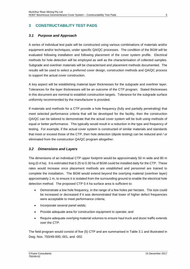
3.2 Dimensions and Layers
The dimensions of an individual CTP upper footprint would be approximately 50 m wide and 80 m long (0.4 ha). It is estimated that 0.25 to 0.30 ha of BGM could be installed daily for the CTP. These rates would increase once placement methods are established and personnel are trained to complete the installation. The BGM would extend beyond the overlying material (overliner layer) approximately 1 m, to ensure it is isolated from the surrounding ground to enable the electrical hole detection method. The proposed CTP 0.4 ha surface area is sufficient to:
• Demonstrate a low hole frequency, in the range of a few holes per hectare. The size could be increased or decreased if it was demonstrated that lower of higher defect frequencies were acceptable to meet performance criteria;
• Incorporate several panel welds;
• Provide adequate area for construction equipment to operate; and
• Require adequate overlying material volumes to ensure haul truck and dozer traffic extends over the CTP.
The field program would consist of five (5) CTP and are summarised in Table 3.1 and illustrated in Dwg. Nos. 750/49-000,-001, and -002.
O’Kane Consultants 15 December 2017 750/49-02

McArthur River Mining Pty Ltd NOEF Bituminous Geomembrane Cover System – Constructability Test Pads 6
Table 3.1: CTP configurations and design specifications.
CTP No. Layers (top down) Comment
1 Base case
• Alluvium, ~0.3 m thick • BGM • HMR subgrade (thickness
established during test strip construction, Section 3.3)
-No restriction on alluvium texture; however, use of a finer texture material compared to full scale construction may result in additional QA/QC oversight (i.e. additional hole detection to verify materials).
2
• Alluvium 0.7 m thick (for 15m wide strip)
• Breccia 0.5 m thick (for 15m wide test strip)
• Alluvial, minimum ~0.2 m thick • BGM • HMR subgrade
-Decrease thickness of alluvium to optimise material use. -Inform on equipment workability for placement of thinner layers.
3
• Alluvium 0.7 m thick (for 15m wide strip)
• Breccia 0.5 m thick (for 15m wide test strip)
• Alluvium, minimum ~0.3 m thick • BGM • Alluvial subgrade
-Address limited HMR availability -Evaluate ‘plastic’ material as a subgrade that may deform under haul loader traffic.
4
• Alluvium 0.7 m thick (for 15m wide strip)
• Breccia nominally ~0.5 m thick • Geotextile protection layer
1,000 g/m2 • BGM • Alluvium subgrade
-Exclude alluvium overliner layer and include geotextile protector over BGM to minimise holes during direct placement of breccia material. -Alluvium subgrade to minimise leakage through holes
5
• Alluvium 0.7 m thick (for 15m wide strip)
• Breccia nominally ~0.5 m thick • * HRM rock overliner ~0.3 m thick • BGM • Alluvium subgrade
-Cover system to increased lateral drainage or coexist as a residual to other cover system alternative to augment lateral drainage capacity. Provider lateral drainage network similar to surface drainage system but placed above BGM. -Address potential instability in alluvium over-liner. -* This would be crushed rock or other product similar to HRM without any geochemical issues.
Given that holes typically occur during geomembrane installation and placement of the overliner layer, the benefit of placement of the remaining cover system layers (topsoil, growth medium and drainage layer) is diminished. However, it is proposed that a 15 m wide strip of the full cover system profile extends across the CTP to verify condition of the BGM and any partial penetrations under the maximum applied overburden pressure. This would be completed on CTP No.2 through No.5 where partial penetrations be expected to vary considerable based on the subgrade and overliner material textures.
The outcomes of the CTPs will provide an understanding of the benefits associated with the material thickness and texture, the use of a geotextile protection layer, and support project objectives as outlined in Section 1.1.
Following completion of the horizontal CTPs, it is likely that two (2) of the CTPs (base case and an alternate) would be constructed on a 1V:4H slope, supported by outcomes from CTPs on the
O’Kane Consultants 15 December 2017 750/49-02

McArthur River Mining Pty Ltd NOEF Bituminous Geomembrane Cover System – Constructability Test Pads 7
plateau. The slope CTP BGM will be seamed to a plateau CTP BGM or anchor trenched and then extended down the slope. This will provide an anchor point and allow evaluation of equipment transitioning over the crest onto the slope.
Nonwoven geotextile, with a mass per unit area of 1,000 g/m² is proposed for the CTPs with direct placement of the breccia drainage rock (No.4 in Table 3.1). If there is a desire, a thinner weight geotextile could be evaluated.
3.3 Test Strip
OKC recommends that a Test Strip is built prior to the CTPs. This will provide an opportunity for equipment selection and methods to be verified prior to constructing the CTPs and increase the probability of meeting CTP project objectives. The working thickness of the subgrade would be established in this stage as well as any specifications for preparing the final surface, such as, but not limited to visual inspection, stone rouging, proof rolling, and smooth-drum compaction.
Following installation of the Test Strip BGM, overliner will be spread to establish an understanding for the workability and lower thickness limit. This would likely be restricted to the alluvium, however.
The Test Strip would be constructed on the plateau and have a surface area in the range of 0.2 ha. The size of the Test Strip would be increased if required to meet project objects. Should the materials and methods not change from the Test Strip then it could be expanded to form a CTP.
3.3.1 Equipment and Methods
Placement and spreading of the materials will likely be completed with a D6 dozer and fleet of articulated trucks (moxies). Construction equipment used for the CTPs will also be used for constructing the full scale cover system. A hydraulic excavator will be required for sampling materials as required and exhuming samples of the BGM. Equipment and methods for preparing the waste rock surface and subgrade will be developed during Test Strip construction.
Material on the plateau would be dumped at the leading edge, spread by the dozer with travel across the completed lift. On the slope, material would be end-dumped at the crest and pushed down-slope. A recent project of OKC in similar conditions used a method of dozing down-slope over the geomembrane. Any longitudinal stresses imposed on the BGM would be documented during the field work.
O’Kane Consultants 15 December 2017 750/49-02

McArthur River Mining Pty Ltd NOEF Bituminous Geomembrane Cover System – Constructability Test Pads 8
4 CONSTRUCTION GUIDANCE AND QA/QC
Construction QA/QC measures will be implemented to ensure the CTPs as-constructed conditions are adequately characterised and they are built in accordance to the respective design and technical guidance. Table 4.1 summarised the proposed material characterisation and BGM cover construction QA/QC program.
Table 4.1: Proposed material characterisation and QA/QC program.
Item Requirement Method Frequency
Waste rock
Prepared surface for subgrade material (to minimise subgrade use)
• Visual • Survey
Continuous As required
Subgrade layer
Particle size distribution (PSD) and water content
• Grizzly % >150 mm • PSD AS1289.3.6.1 and WC
AS1289.2.1.1
6 per CTP 6 per CTP
CTP layout and digital elevation model • Total station or LiDAR Continuous
Prepared surface free of protruding stones, irregularities, organics and ruts
• Visual • Survey
Continuous As required
BGM Product meets specifications
• Labelling, transportation, storage
• Thickness ASTM D5199 • Density ASTM D792 • Tensile shear ASTM D4595-86
Continuous 1 per 500m 1 per 500m 1 per 1000m
Product free of defects • Visual Continuous
Adjoining panels overlap as specified and clean of debris • Visual Continuous
Seam continuity
• Air lance ASTM D4437 • Vacuum ASTM D5641 • Ultrasonic ASTM D7006 • Mechanical resistance
ASTM D-7056 • Visual
1 per 100m 1 m per 100m 1 per 500m Continuous
Hole detection (installed BGM, prior to overliner layer placement)
• Visual • ASTM D7703 Water lance
Continuous 1 (minimum)
Hole detection (overliner layer constructed)
• Dipole (ASTM D7007) o Install engineered holes
(ASTM D7909)
1 (minimum)
Repairs • Torch and patch • Vacuum ASTM 5641
As required As required
Impregnation by overliner layer / subgrade layer
• Test pit exhume 1 x 1 m BGM section
2-4 per CTP
Longitudinal stress (slope only) Subjective assessment
• Test pit expose 2 x 2 m BGM section
• Perpendicular and parallel cut to observe any opening of cut
4 per CTP
Geotextile Product meets specifications • Labelling • Transportation • Storage
Continuous
Adjoining panels overlap or seamed as specified
• Visual
Continuous
Installed panels free of defects • Visual Continuous
Overliner layer PSD and water content
• Visual • Grizzly % >150 mm • PSD AS1289.3.6.1 and WC
AS1289.2.1.1
Continuous 6 per CTP 6 per CTP
Layer thickness • Total station or LiDAR As required
Inspect placement (free of stones and irregularities) • Visual Continuous
O’Kane Consultants 15 December 2017 750/49-02

McArthur River Mining Pty Ltd NOEF Bituminous Geomembrane Cover System – Constructability Test Pads 9
A technical representative of the manufacture shall be on site for the BGM to ensure the specified handling and installation procedures are used. The representative shall remain on site until it is determined that the installation personnel are qualified to transport the BGM from storage to the CTP area, install, and seam the BGM.
4.1 Subgrade Layer
4.1.1 Survey Control
Initially the lines and grades for the layout of each CTP will be established. Survey will be completed as required to verify the as-constructed layer thickness and tolerances. The finished surface of the waste rock shall be dense and uniform to allow for placement of the subgrade layer to meet specification. The subgrade layer shall be placed using the materials and methods developed during the Test Strip. Exceedance of topographic highs greater than 0.05 m over 3 m in the subgrade should be avoided as per manufactures specifications. Smaller defects over a much shorter distance should also be avoided (Coletanche, 2014).
4.1.2 Material Characterisation
Samples of subgrade material shall be submitted for geotechnical testing (PSD and water content). Each sample will consist of one half filled 20 L pail, labelled accordingly. Sample will be collected as the material is being placed to grade on the waste rock.
A grizzly will be used in the field to estimate the oversized fraction for samples collected for PSD analysis. This will provide a correction for laboratory particle size distribution test results and assist in visually estimating the oversized fraction as the dozer is pushing out the leading edge. Assessment of stones in the subgrade and overliner is important given that stone penetrations are one of the top two causes of holes that occur in geomembranes during construction.
4.2 BGM
4.2.1 Acceptance and Conformance Testing
Before delivery of the BGM verification is required to confirm that the product supplied is the material specified in the contract. The supplier shall ensure that the manufacture has provided labels on each roll including:
• Manufacture
• Type of BGM
• Roll identification number, shipping weight, thickness, length and width;
• Manufactures’ approved QC stamp, QC test results;
• Location and type of flaws; and
• Required certifications.
O’Kane Consultants 15 December 2017 750/49-02

McArthur River Mining Pty Ltd NOEF Bituminous Geomembrane Cover System – Constructability Test Pads 10
The recommended BGM conformance tests includes the following at a frequency of 1 per 10 roles:
• Thickness ASTM D5199;
• Density ASTM D792;
• Dimensional change (longitudinal and transverse) ASTM D1204-02;
• Stress relaxation CEBTP 6327.7.390;
• Static puncture ASTM D4833
• Stress cracking ASTM D1693; and
• Coefficient of thermal expansion ASTM D696
4.2.2 Visual Inspection
Inspection of the BGM is continuous and primarily focused on the identification of any defects or holes as well as ensuring that there is adequate overlap of subsequent panels and all seam overlaps are free of debris. Construction equipment deploying the BGM rolls shall not deform or rut the subgrade material excessively. Tyre and track deformation shall not exceed 25 mm.
4.2.3 Inspection of Seamed Panels
Following completion of seam welds, inspection of bitumen bleed from the seam should be observed. Where a bleed is not observed, a trowel can be used to test the weld. Any location of excessive heating will be documented and repaired accordingly. Non-destructive tests (ultra-sound, vacuum, and air lance) and destructive tests are to be completed for seam QC. Testing on extracted samples includes, density, thickness, and tensile shear strength. The aforementioned destruction testing as well as shear strength on the BGM itself (i.e. not a weld) will serve to support compliance testing of the BGM.
4.2.4 Water Lance Hole Survey
The water lance method will be used for detection of holes and defects after completion of the BGM installation and prior to placement of the overliner layer.
4.2.5 Exhumed BGM
One-metre square sections of BGM will be sampled from under subsections of the CTP constructed to the full cover profile. The exhumed samples will be inspected for partially penetrating holes and submitted to a qualified laboratory for assessment of thickness.
Larger two-metre square sections of the BGM will be exposed on the slope to assess differences in longitudinal stresses. A 1.5 m cut in the BGM will be made parallel and perpendicular to the slope with any expansion of the opening documented.
O’Kane Consultants 15 December 2017 750/49-02

McArthur River Mining Pty Ltd NOEF Bituminous Geomembrane Cover System – Constructability Test Pads 11
4.2.6 Dipole Hole Survey Detection
The dipole method of hole detection is used for geomembranes covered with a overliner layer. Defects and holes represent the most significant damage that occur during material placement. The resolution of the survey is dependent on factors such as the water content, thickness and texture of the protection layer, quality of contact with subgrade layer, and the use of any geotextile products. Prior to covering the BGM, engineered holes as described in Table 4.2 will be placed at a known location of the BGM to verify the resolution of the dipole method on each CTP. Depending on the field responses the size and number of engineered holes may be modified. Methods outlined in ASTM D7909 will be followed.
Table 4.2: Engineered holes to verify dipole method for each CTP.
Number of Holes / CTP
Dimensions (mm2) Description
4 3 Pinhole
4 78 Hole
4 7 Cut
4.3 Geotextile
4.3.1 Acceptance and Conformance Testing
A geotextile will be a nonwoven geotextile with a mass per unit area of 1,000 g/m². Verification is required to confirm that the geotextile supplied is the material specified in the contract. ASTM D4759 should be followed for conformance testing of geotextiles.
4.3.2 Visual Inspection of Seamed Sheets
Inspection of the geotextile is continuous and primarily focused on the identification of any defects and subsequent panels and all seams are complete.
4.3.3 Deployment
Deployment of the geotextile over the BGM will be limited to pneumatic tires or all-terrain vehicles with low ground contact pressure. The QA/QC engineer will monitor all activities on the surface of the BGM to ensure no damage occurs during placement. Nonwoven geotextiles may ‘stick’ to the textured BGM and can cause some challenges with alignment.
4.3.4 Seaming
Protective geotextile seams are typically heat bonded. Seaming methods will be verified following selection of an appropriate geotextile product.
O’Kane Consultants 15 December 2017 750/49-02

McArthur River Mining Pty Ltd NOEF Bituminous Geomembrane Cover System – Constructability Test Pads 12
4.4 Overliner Layer
4.4.1 Survey Control
The overliner layer shall be either an alluvium or breccia material with no restriction on gradation. The overliner layers shall be placed in one lift to the design grades as indicated on the drawings or as required by the project supervisor. The overliner layer shall conform to the prescribed thickness to the extent possible. Evaluation of the minimum layer thickness will be established during the Test Strip program.
4.4.2 Material Characterisation
Samples of the overliner material shall be submitted to geotechnical testing (particle size distribution and water content). Each sample will consist of one to five 20 L pails, with each sample pail labelled accordingly. A grizzly will be used in the field to estimate the oversized fraction for samples collected for PSD analysis.
O’Kane Consultants 15 December 2017 750/49-02

McArthur River Mining Pty Ltd NOEF Bituminous Geomembrane Cover System – Constructability Test Pads 13
5 CONSTRUCTION SCHEDULE
A schedule for the CTPs is presented in Table 5.1. The schedule is based on the anticipated timeline, although actual timing of some tasks may vary from what is shown based on contractor requirements. It is assumed that BGM will be installed at a rate of 0.3 ha per day for the proposed scheduling and this will set overall progress. OKC understand that construction materials will be stockpiled near the CTP location and hence, construction of the cover system would be completed at a rate equal to or near the rate of BGM installation. The schedule also assume that the Test Strip will be built into CTP No.1.
Table 5.1: Estimate schedule for construction of the Test Strip and CTPs.
Task Description Details Cumulative Timeline (Days)
Test Strip • -Develop methods and tolerances for subgrade • Install Test Strip BGM • -Develop methods and tolerances for overliner
2
Begin Subgrade • -Prepare subgrade for CTP No.1 through No.5 (ongoing) 2.5
Begin CTP No.1 • -Install BGM CTP No.1 3.25
Begin CTP No.2 • -Install BGM CTP No.2 • -Water lance CTP No.1 and place overliner
4.5
Begin CTP No.3 Complete CTP No.1
• -Install BGM CTP No.3 • Water lance CTP No.2 and place overliner • -Dipole test CTP No.1 and sample BGM
5.75
Begin CTP No.4 Complete CTP No.2
• -Install BGM CTP No.4 • Water lance CTP No.3 and place overliner • -Dipole test CTP No.2 and sample BGM
7
Begin CTP No.5 Complete CTP No.3
• -Install BGM CTP No.5 • -Water lance CTP No.4 and place overliner • -Dipole test CTP No.3 and sample BGM
8.25
Begin Slope CTP No.6 Complete CTP No.4
• -Install BGM Slope CTP No.6 • -Water lance CTP No.5 and place overliner • Dipole test CTP No.4 and sample BGM
9.5
Begin Slope CTP No.7 Complete CTP No.5
• -Install BGM Slope CTP No.7 • -Water lance Slope CTP No.6 and place overliner • Dipole test CTP No.5 and sample BGM
10.75
Complete Slope CTP No.6
• -Water lance Slope CTP No.7 and place overliner • -Dipole test Slope CTP No.6 and sample BGM
12
Complete Slope CTP No.7
• Dipole test Slope CTP No.7 and sample BGM • Complete the remaining QA/QC and sampling /
characterisation of the BGM 13
O’Kane Consultants 15 December 2017 750/49-02

McArthur River Mining Pty Ltd NOEF Bituminous Geomembrane Cover System – Constructability Test Pads 14
6 CTP MATERIAL QUANTITIES
The estimated quantities of materials required for the CTP are summarised in Table 6.1. The quantities shown assume 50 m x 80 m (0.4 ha) CTP dimensions (each). 10% has been added for geosynthetic surface required (both BGM and geotextile) to account for seam overlap and wastage. Given that the slope CTP configurations will be based on outcomes from the plateau, it is assumed for the purpose of quantities that CTP No.6 is constructed as the base case and CTP No.7 includes a geotextile protection layer.
Table 6.1: Bill of quantities.
CTP Material Quantity
1
Alluvium, ~0.3 m thick 1,200 m3
BGM 4,400 m2
HMR subgrade ~0.2 m thick (assumed) 800 m3
2
Alluvium 0.7 m thick (for 15m wide strip) 840 m3
Breccia 0.5 m thick (for 15m wide strip) 600 m3
Alluvial, minimum ~0.2 m thick 800 m3
BGM 4,400 m2
HMR subgrade ~0.1 m thick (assumed) 400 m3
3
Alluvium 0.7 m thick (for 15m wide strip) 840 m3
Breccia 0.5 m thick (for 15m wide strip) 600 m3
Alluvium, minimum ~0.3 m thick 1,200 m3
BGM 4,400 m2
Alluvial subgrade ~0.2 m thick (assumed) 800 m3
4
Alluvium 0.7 m thick (for 15m wide strip) 840 m3
Breccia nominally ~0.5 m thick 2,000 m3
Geotextile protection layer (1,000 g/m2) 4,400 m2
BGM 4,400 m2
Alluvium subgrade ~0.2 m thick (assumed) 800 m3
5
Alluvium 0.7 m thick (for 15m wide strip) 840 m3
Breccia nominally ~0.5 m thick (for 15m wide strip) 600 m3
HMR rock overliner ~0.3 m thick 1,200 m3
BGM 4,400 m2
Alluvium subgrade ~0.2 m thick (assumed) 800 m3
6 Slope
Breccia 1.2 m (for 15m wide strip) 1,600 m3
Alluvium ~0.3 m thick 1,200 m3
BGM 4,400 m2
Alluvium subgrade ~0.2 m thick (assumed) 800 m3
7 Slope
Breccia 0.5 (plus 1 m thick for 15 m wide full profile) 3,600 m3
Geotextile protection layer (1,000 g/m2) 4,400 m2
BGM 4,400 m2
HRM subgrade ~0.2 m thick (assumed) 800 m3
O’Kane Consultants 15 December 2017 750/49-02

McArthur River Mining Pty Ltd NOEF Bituminous Geomembrane Cover System – Constructability Test Pads 15
Table 6.2 summarises the total material volumes for the CTPs. Approximately 2,000 m2 of BGM was added to the total to account for the Test Strip. This assumes that the Test Strip BGM is damaged and not incorporated into CTP No.1.
Table 6.2: Total bill of quantities.
CTP Material Quantity
Total
Alluvium 10,960 m3
Breccia 9,000 m3
HMR 3,200 m3
BGM 32,800 m2
Geotextile (1000 g/m2) 8,800 m2
O’Kane Consultants 15 December 2017 750/49-02

McArthur River Mining Pty Ltd NOEF Bituminous Geomembrane Cover System – Constructability Test Pads 16
REFERENCES
AS 1289.2.1.1.:Soil moisture content tests—Determination of the moisture content of a soil - Oven drying method (standard method)
AS1289.3.6.1. Soil classification tests—Determination of the particle size distribution of a soil - Standard method of analysis by sieving
ASTM D4437. Standard Practice for Non-destructive Testing (NDT) for Determining the Integrity of Seams Used in Joining Flexible Polymeric Sheet Geomembranes
ASTM D4595. Standard Test Method for Tensile Properties of Geotextiles by Wide-Width Strip Method
ASTM D4759-11. Guide for determining the specification conformance of geosynthetics.
ASTM D5199. Standard Test Method for Measuring the Nominal Thickness of Geosynthetics.
ASTM D5641. Standard Practice for Geomembrane Seam Evaluation by Vacuum Chamber
ASTM D7006-03. Standard Practice for Ultrasonic Testing of Geomembranes
ASTM D7007-16. Standard Practices for Electrical Methods for Locating Leaks in Geomembranes Covered with Water or Earth Materials
ASTM D7056-07. Standard Test Method for Determining the Tensile Shear Strength of Pre-Fabricated Bituminous Geomembrane Seams.
ASTM D792. Standard Test Methods for Density and Specific Gravity (Relative Density) of Plastics by Displacement.
Breul, B., Caron, M., Cote, J. and Stenson, G. (2004). Durability of Bituminous Geomembrane Water Proofing. 57th Canadian Geotechnical Conference. 30–37.
Breul, B., Carroget, J., Herment, R., (1998), “Automatic Ultrasound Seam Tester for Bituminous Geomembranes – Development and Field Results”, Proceedings Sixth International Conference on Geosynthetics, Industrial Fabrics Association international, Roseville, MN, pp 345-348.
Coletanche (2014). Design and application handbook – Study and operation of projects with Coletanche geomembrane.
Cunning, J., Isidoro, A., & Eldridge, T. (2008). Dam Construction at Diavik using Bituminous Geomembrane Liners. Proceedings of the 61st Canadian Geotechnical Conference, GeoEdomonton’08, Edmonton, Alberta. September 21-24, 2008., 933–939.
Environment Agency (EA), (2004). The likely medium to long-term generation of defects in geomembrane liners. R&D Technical Report P1-500/1/TR. EA, Bristol
Forget, B., Rollin, a L., & Jacquelin, T. (2005). Lessons Learned from 10 Years of Leak detection Surveys on Geomembranes. Sardinia Symposium.
Nosko, V., Andrezal, T., Gregor, T. and Ganier, P. (1996). SENSOR Damage Detection System (DDS) - The unique geomembrane testing method. In Geosynthetics: applications, design and
O’Kane Consultants 15 December 2017 750/49-02

McArthur River Mining Pty Ltd NOEF Bituminous Geomembrane Cover System – Constructability Test Pads 17
construction. Ed., De Groot, M. B., den Hoedt, G., Termaat, R. J., Proc., 1st European Geosynthetics Conf., EUROGEO1, Maastricht, Netherlands. Balkema, Rotterdam, 743-748.
McQuade, S.J. and Needham, A.D. (1999). Geomembrane liner defects – causes, frequency and avoidance. Geotechnical Engineering, Proc. Instn. Civ. Eng., 137, 203-213.
Peggs, I. D. (2003). Geomembrane Liner Durability: Contributing Factors and the Status Quo. UK International Geosynthtic Conference. March.
O’Kane Consultants 15 December 2017 750/49-02

Appendix A
Drawings

50
75
45
55
60
65
70
80
80
80
85
85
9090
75
75
100
100
50
SCALE 1:2500
025 25 75 100 125m
LEGENDEXISTING CONTOUR
EXISTING DRAINAGE PATH
PROPOSED SITE BDY
NOTES1. ALL UNITS IN METRES U.N.O.2. DO NOT SCALE
50
EXISTING FEATURES PLAN1:2500 Integrated Mine Waste Management and Closure Services
O'Kane
Specialists in Geochemistry and Unsaturated Zone Hydrology
Consultants Pty Ltd.
REFE
RENC
E
REVI
SION
SDESCRIPTIONDWG. NO. DESCRIPTIONNO. DRN. BY: DATE
DWG. NO.: REV.:OKC RPT. NO.:SCALE:
CLIENT/PROJECT:
PRODUCED BY:
OKC PROJECT NO.:
DRN. BY:
APPD. BY:
DATE:
DATE:
APPD. BY:
PAGE SIZE:
THIS DRAWING IS TO BE READ IN CONJUNCTION WITH OKC REPORT
750/49
LOCATION PLAN
A750-49-000
14.11.17
14.11.17
750/49
N.TAGHIZADEH
P. GARNEAU
AS SHOWN
A ISSUED FOR INFORMATION N.T 14.11.17P.G
A3750-49
PLATEAU CONSTRUCTION TESTING
SLOPE CTP
PROPOSED PAD OUTLINE (TYP.)
CTP NO. 1CTP NO. 2
CTP NO. 3CTP NO. 4
PRELIMINARY
NOT FOR CONSTRUCTIONSUBJECT TO FINAL APPROVAL
CTP NO. 5
CTP NO. 6CTP NO. 7

Integrated Mine Waste Management and Closure Services
O'Kane
Specialists in Geochemistry and Unsaturated Zone Hydrology
Consultants Pty Ltd.
REFE
RENC
E
REVI
SION
SDESCRIPTIONDWG. NO. DESCRIPTIONNO. DRN. BY: DATE
DWG. NO.: REV.:OKC RPT. NO.:SCALE:
CLIENT/PROJECT:
PRODUCED BY:
OKC PROJECT NO.:
DRN. BY:
APPD. BY:
DATE:
DATE:
APPD. BY:
PAGE SIZE:
THIS DRAWING IS TO BE READ IN CONJUNCTION WITH OKC REPORT
750/49
CONTRACTIBILITY TEST PADS PLAN
A750-49-001
08.11.17
09.11.17
750/49
N.TAGHIZADEH
P. GARNEAU
AS SHOWN
A ISSUED FOR INFORMATION N.T 14.11.17P.G
A3750-49
PRELIMINARY
NOT FOR CONSTRUCTIONSUBJECT TO FINAL APPROVAL
SITE TEST PADS PLAN1:1500
APPROXIMATED SITEBOUNDARY OUTLINE
NOTE
1. ALL UNITS IN METRES U.N.O.
CREST
PROPOSED PADOUTLINE (TYP.).
BGM
ROLL WIDTH 5.1m
(0.2m OVERLAP)
500
SCALE 1:25
0250 250 1000750 1250mm
..\..\IMAGES\MRM Logo Hi-res.png
15.0m WIDE FULL
COVER PROFILE.
REFER DETAIL.
50.0
4.8
80
.0
20.0
30.0
BGM
WASTE ROCK
OVERLINER
TYPICAL DETAIL1:25
SUBGRADE
NOTE:
1.0m WIDE EXPOSED BGM TO
FACILITATE QA/QC WITH DIPOLE
METHOD.
1.0m
CTP NO. 1
CTP NO. 2 CTP NO. 4
CTP NO. 3
CTP NO. 5
WASTE ROCK
100 mm TOPSOIL
600 - 900 mm ALLUVIUM LAYER
(GROWTH MEDIUM)
200 - 500 mm BRECCIA LAYER
(DRAINAGE LAYER)
100m
m MI
N.
TYPICAL FULL COVER PROFILE DETAIL1:25
REFER DRG 750-49-002 FOR
BGM PROFILE DETAILS.

WASTE ROCK
300 mm NOMINAL THICKNESS ALLUVIUM OVERLINER
TYPICAL CTP NO. 1 (BASE CASE) DETAIL1:25
HMR SUBGRADE
MAX 50mm DEVIATION PER
3000m LATERAL DISTANCE
BGM
NOTE:
DECREASE THICKNESS OF ALLUVIUM
TO OPTIMIZE MATERIAL USE.
TYPICAL CTP NO. 2 DETAIL1:25
WASTE ROCK
200 mm NOMINAL THICKNESS ALLUVIUM OVERLINER
HMR SUBGRADE
MAX 50mm DEVIATION
PER 3000mm LATERAL
DISTANCE
BGM
NOTE:
ADDRESS LIMITED HMR AVAILABILITY
AND USE OF 'PLASTIC' MATERIAL AS A
SUBGRADE.
TYPICAL CTP NO. 3 DETAIL1:25
BGM
WASTE ROCK
300 mm NOMINAL THICKNESS ALLUVIUM OVERLINER
ALLUVIUM SUBGRADE
MAX 50mm DEVIATION PER
3000mm LATERAL DISTANCE
NOTE:
EXCLUDE ALLUVIUM OVERLINER AND
INCLUDE GEOTEXTILE PROTECTOR
OVER BGM.
TYPICAL CTP NO. 4 DETAIL1:25
GEOTEXTILE PROTECTION
LAYER 1,000 g/m²
WASTE ROCK
500 mm NOMINAL THICKNESS BRECCIA OVERLINER
ALLUVIUM SUBGRADE
MAX 50mm DEVIATION PER 3000mm
LATERAL DISTANCE
BGM
NOTE:
DRAINAGE LAYER OVER BGM.
TYPICAL CTP NO. 5 DETAIL1:25
WASTE ROCK
ALLUVIUM SUBGRADE
MAX 50mm DEVIATION
PER 3000mm LATERAL
DISTANCE
BGM
300 mm NOMINAL THICKNESS HMR OVERLINER
Integrated Mine Waste Management and Closure Services
O'Kane
Specialists in Geochemistry and Unsaturated Zone Hydrology
Consultants Pty Ltd.
REFE
RENC
E
REVI
SION
SDESCRIPTIONDWG. NO. DESCRIPTIONNO. DRN. BY: DATE
DWG. NO.: REV.:OKC RPT. NO.:SCALE:
CLIENT/PROJECT:
PRODUCED BY:
OKC PROJECT NO.:
DRN. BY:
APPD. BY:
DATE:
DATE:
APPD. BY:
PAGE SIZE:
THIS DRAWING IS TO BE READ IN CONJUNCTION WITH OKC REPORT
750/49
CONTRACTIBILITY TEST PADS DETAILS
A750-49-002
08.11.17
09.11.17
750/49
N.TAGHIZADEH
P. GARNEAU
AS SHOWN
A ISSUED FOR INFORMATION N.T 14.11.17P.G
A3750-49
500
SCALE 1:25
0250 250 1000750 1250mm
NOTE
1. ALL UNITS IN MILLIMETERS U.N.O.
PRELIMINARY
NOT FOR CONSTRUCTIONSUBJECT TO FINAL APPROVAL