Embed Size (px)
Citation preview

•..••.............•.•••............••••••••....
Appendix
Typical weights and live loads
1 lb = 0.454 kg = 4.448 N force 1 lb/fl? = 4.88 kg/m2 = 47.9 N/m2
1lb/ft3 = 16.02 kg/m3 = 157 N/m3
Weights kN/m3
Aluminium, cast 26 Asphalt paving 23 Bricks, common 19 Bricks, pressed 22 Clay, dry 19-22 Clay, wet 21-25 Concrete, reinforced 24 Glass, plate 27 Lead 112 Oak 9.5 Pine, white 5 Sand, dry 16-19 Sand, wet 18-21 Steel 77 Water 9.81
kN/m2
Brick wall, 115 mm thick 2.6 Gypsum plaster, 25 mm thick 0.5 Glazing, single 0.3
Floor and roof loads kN/m2
Classrooms 3.0 Dance halls 5.0 Flats and houses 1.5 Garages, passenger cars 2.5 Gymnasiums 5.0 Hospital wards 2.0 Hotel bedrooms 2.0 Offices for general use 2.5 Flat roofs, with access 1.5 Flat roofs, no access 0.75
374
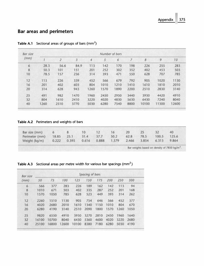
Bar areas and perimeters
Table A.l Sectional areas of groups of bars (mm2)
Bar size Number of bars (mm) 2 3 4 5 6
6 28.3 56.6 84.9 113 142 170 8 50.3 101 151 201 252 302
10 78.5 157 236 314 393 471
12 113 226 339 452 566 679 16 201 402 603 804 1010 1210 20 314 628 943 1260 1570 1890
25 491 982 1470 1960 2450 2950 32 804 1610 2410 3220 4020 4830 40 1260 2510 3770 5030 6280 7540
Table A.2 Perimeters and weights of bars
Bar size (mm) Perimeter (mm) Weight (kg/m)
6 8 18.85 25.1 0.222 0.395
10 12 16 31.4 37.7 50.2 0.616 0.888 1.579
7 8
198 226 352 402 550 628
792 905 1410 1610 2200 2510
3440 3930 5630 6430 8800 10100
20 25 62.8 78.5 2.466 3.854
Appendix 375
9 70
255 283 453 503 707 785
1020 1130 1810 2010 2830 3140
4420 4910 7240 8040
11300 12600
32 40 100.5 125.6 6.313 9.864
Bar weights based on demity of 7B50 kglm' .
Table A.3 Sectional areas per metre width for various bar spacings (mm2 )
Bar size Spacing of bars
(mm) 50 75 100 725 750 775 200 250 300 6 566 377 283 226 189 162 142 113 94 8 101 0 671 503 402 335 287 252 201 168
10 1570 1050 785 628 523 449 393 314 262
12 2260 1510 1130 905 754 646 566 452 377 16 4020 2680 2010 1610 1340 1150 1010 804 670 20 6280 4190 3140 2510 2090 1800 1570 1260 1050
25 9820 6550 4910 3930 3270 2810 2450 1960 1640 32 16100 10700 8040 6430 5360 4600 4020 3220 2680 40 25100 16800 12600 10100 8380 7180 6280 5030 4190
376 Appendix
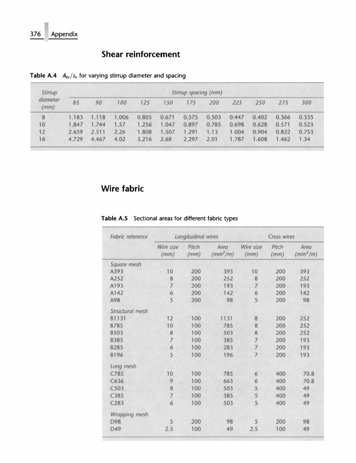
Shear reinforcement
Table AA Asv/sv for varying stirrup diameter and spacing
Stirrup Stirrup spacing (mm) diameter 85 90 100 125 150 775 200 225 250 275 300 (mm)
8 1.183 1.118 1.006 0.805 0.671 0.575 0.503 0.447 0.402 0.366 0.335 10 1.847 1.744 1.57 1.256 1.047 0.897 0.785 0.698 0.628 0.571 0.523 12 2.659 2.511 2.26 1.808 1.507 1.291 1.13 1.004 0.904 0.822 0.753 16 4.729 4.467 4.02 3.216 2.68 2.297 2.01 1.787 1.608 1.462 1.34
Wire fabric
Table A.5 Sectional areas for different fabric types
Fabric reference Longitudinal wires Cross wires
Wire size Pitch Area Wire size Pitch Area (mm) (mm) (mm2/m) (mm) (mm) (m~/m)
Squore mesh A393 10 200 393 10 200 393 A252 8 200 252 8 200 252 A193 7 200 193 7 200 193 A142 6 200 142 6 200 142 A98 5 200 98 5 200 98
Structural mesh 81131 12 100 1131 8 200 252 8785 10 100 785 8 200 252 8503 8 100 503 8 200 252 8385 7 100 385 7 200 193 8285 6 100 283 7 200 193 8196 5 100 196 7 200 193
Long mesh C785 10 100 785 6 400 70.8 C636 9 100 663 6 400 70.8 C503 8 100 503 5 400 49 C385 7 100 385 5 400 49 C283 6 100 503 5 400 49
Wropping mesh 098 5 200 98 5 200 98 049 2.5 100 49 2.5 100 49
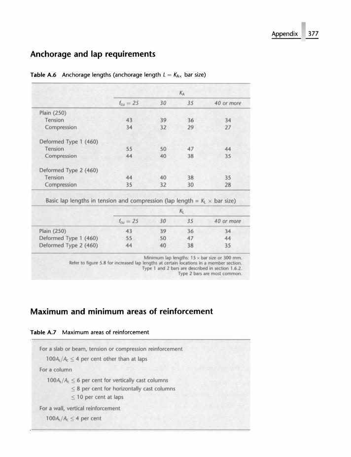
Anchorage and lap requirements
Table A.6 Anchorage lengths (anchorage length L = KAx bar size)
KA
feu = 25 30 35 40 or more Plain (250)
Tension 43 39 36 34 Compression 34 32 29 27
Deformed Type 1 (460) Tension 55 50 47 44 Compression 44 40 38 35
Deformed Type 2 (460) Tension 44 40 38 35 Compression 35 32 30 28
Basic lap lengths in tension and compression (lap length = KL x bar size)
Kl
feu = 25 30 35 40 or more Plain (250) 43 39 36 34 Deformed Type 1 (460) 55 50 47 44 Deformed Type 2 (460) 44 40 38 35
Minimum lap lengths: 15 x bar size or 300 mm. Refer to figure 5.8 for inoeased lap lengths at certllin locations in a member section.
Type 1 and 2 bars are described in section 1.6.2. Type 2 bars are most common.
Maximum and minimum areas of reinforcement
Table A.7 Maximum areas of reinforcement
For a slab or beam, tension or compression reinforcement
1 OOA,/ A.: ::;; 4 per cent other than at laps
For a column
1 OOA,/ A.: ::;; 6 per cent for vertically cast columns
::;; 8 per cent for horizontally cast columns
< 10 per cent at laps
For a wall, vertical reinforcement
1 OOA, / A.: :S 4 per cent
Appendix 377
378 Appendix
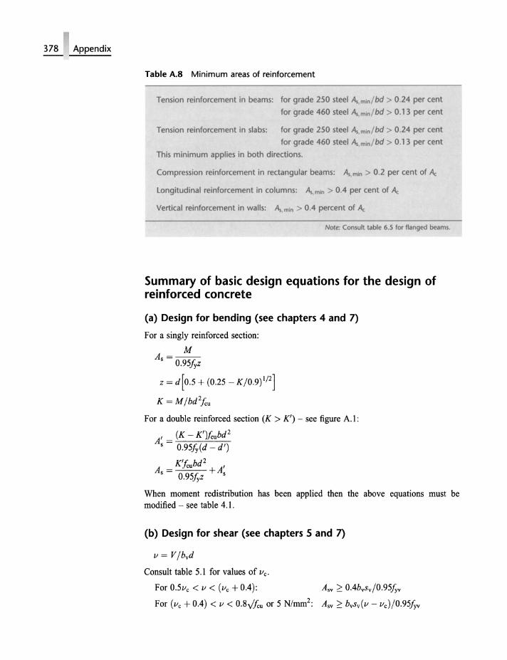
Table A.S Minimum areas of reinforcement
Tension reinforcement in beams: for grade 250 steel A",mln/bd > 0.24 per cent
for grade 460 steel A, mini bd > 0.1 3 per cent
Tension reinforcement in slabs: for grade 250 steel A.,mln/ bd > 0.24 per cent
for grade 460 steel A"mln/ bd > 0.13 per cent
This minimum applies in both directions.
Compression reinforcement in rectangular beams: A., mln > 0.2 per cent of Ac
Longitudinal reinforcement in columns: A..min > 0.4 per cent of Ac
Vertical reinforcement in walls: A •. mln > 0.4 percent of Ac
Note: Consult table 6.5 for flanged be"ms.
Summary of basic design equations for the design of reinforced concrete
(a) Design for bending (see chapters 4 and 7) For a singly reinforced section:
M As=--
0.95hz
z = d[0.5 + (0.25 - K/O.9)1/2]
K = M/bd 2/cu For a double reinforced section (K > K') - see figure A.I:
A' = (K - K')fcubd2 s 0.95h(d - d')
As = K'!cubd2 + A' 0.95hz s
When moment redistribution has been applied then the above equations must be modified - see table 4.1.
(b) Design for shear (see chapters 5 and 7)
v = V/bvd
Consult table 5.1 for values of Vc.
For 0.5vc < v < (vc + 0.4):
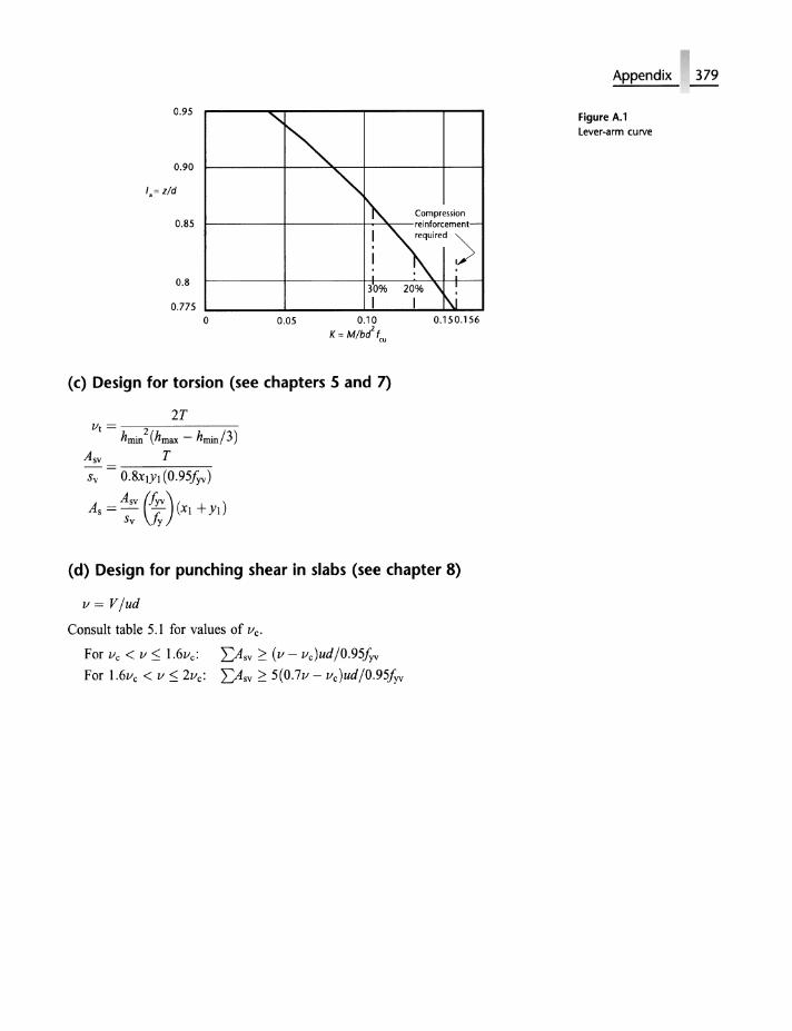
0.95
0.90
1,= z/d
0.85
0.8
0.775 o
........
~
0.05
'" ~ Compression
"\"~~-! reqUired>
I I . . 30% 20% \ ~ I I I\J
0.10 K= M/bd\u
0.150.156
(c) Design for torsion (see chapters 5 and 7)
2T VI = --;;2:------
hmin (hmax - hmin /3) Asv T Sv O.8XlYl (O.95fyv)
As = ~:v fir) (Xl + Yl)
(d) Design for punching shear in slabs (see chapter 8)
V = V/ud
Consult table 5.1 for values of Vc.
For Vc < v ~ 1.6vc: Dsv ;:::: (v - vc)ud/O.95fyv For 1.6vc < v ~ 2vc: Dsv;:::: 5(O.7v - vc )ud/O.95fyv
Appendix 379
Figure A.l Lever-arm curve
380
Further reading
(a) British Standards and Eurocodes
BS 1881 BS 4449 BS 4466
BS 4482 BS 4483 BS 5057
BS 5328 BS 5896
BS 5950
BS 6399 BS 8002 BS 8004 BS 8007
BS 8110
Methods of testing concrete Specification for carbon steel bars for the reinforcement of concrete Specification for bending dimensions and scheduling of reinforcement for concrete Cold reduced steel wire for the reinforcement of concrete Steel fabric for the reinforcement of concrete Concrete admixtures Part 1: Guide to specifYing concrete Specification for high tensile steel wire and strand for the prestressing of concrete Structural use of steelwork on buildings. Part 3: Design in composite construction Design loading for buildings Earth retaining structures Foundations Code of practice for the design of concrete structures for retaining aqueous liquids Structural use of concrete, Parts 1, 2 and 3
DD ENV 1992-1-1 Eurocode 2; Design of concrete structures. Part 1 DD ENV 206 Concrete - performance, production, placing and compliance criteria Draft prEN 10080 Steel for the reinforcement of concrete
(b) Textbook and other publications
A. W. Beeby and R. S. Narayanan, Designers Handbook to EuroCode 2. Thomas Telford, London, 1995. lH. Bungey and S. G. Millard, The Testing of Concrete in Structures, 3rd edn. Chapman & Hall, London, 1995. R. Hulse and W. H. Mosley, Reinforced Concrete Design by Computer. Macmillan, Basingstoke, 1986.
R. Hulse and W. H. Mosley, Prestressed Concrete Design by Computer. Macmillan, Basingstoke, 1987. M. K. Hurst, Prestressed Concrete Design, 2nd edn. Chapman & Hall, London, 1998.
F. K. Kong and R. H. Evans, Reinforced and Prestressed Concrete. Chapman & Hall, London, 1988. R.M. Lawson, Commentary on BS 5950 Part 3 Section 3.1, Composite Beams. The Steel Construction Institute, 1990. T. Y. Lin and N. H. Bums, Design of Prestressed Concrete Structures. J. Wiley, Chichester, 1983. T. J. MacGinley and B. S. Choo, Reinforced Concrete Design Theory and Examples. E & F N Spon, London, 1990. W. H. Mosley, R. Hulse and J. H. Bungey, Reinforced Concrete Design to Eurocode 2. Macmillan, Basingstoke, 1996. A. M. Neville, Properties of Concrete, 4th edn. Longman Scientific and Technical, Harlow, 1998. A. M. Neville and J. J. Brooks, Concrete Technology. Longman Scientific and Technical, Harlow, 1987. A. H. Nilson and G. Winter, Design of Concrete Structures. McGraw-Hill, Maidenhead, 1991. C. E. Reynolds and J. C. Steedman, Reinforced Concrete Designer's Handbook, 10th edn. E & F N Spon, London, 1988. Concise EuroCode for the Design of Concrete Buildings. British Cement Association, Crowthome, Berks, 1993. Worked Examples for the Design of Concrete Buildings. British Cement Association, Crowthome, Berks, 1994.
Further reading 381
•..•••••..........••••••...•......••
382
Index
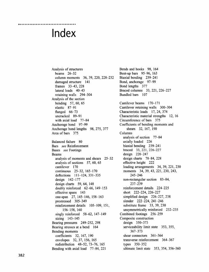
Analysis of structures beams 26-32 column moments 36, 39, 220, 228-232 damaged structure 141 frames 33-43, 228 lateral loads 40-43 retaining walls 294-304
Analysis of the section bending 57, 60, 65 elastic 87-91 flanged 66-73 uncracked 89-91 with axial load 77-84
Anchorage bond 97-99 Anchorage bond lengths 98,275,377 Area of bars 375
Balanced failure 80 Bars see Reinforcement Bases see Footings Beams
analysis of moments and shears 25-32 analysis of sections 57, 60, 65 cantilever 170 continuous 25-32, 165-170 deflections 111-124,331-335 design 142-177 design charts 59, 64, 148 doubly reinforced 62--66, 149-153 effective spans 143 one-span 27, 145-146, 158-163 prestressed 305-349 reinforcement details 105-109, 151,
156-158, 160 singly reinforced 58--62, 147-149 sizing 143-145
Bearing pressures 249-252, 298 Bearing stresses at a bend 164 Bending moments
coefficients 32, 167, 190 envelopes 32, 37, 156, 165 redistribution 48-52, 73-76, 165
Bending with axial load 77-84,221
Bends and hooks 98, 164 Bent-up bars 95-96, 163 Biaxial bending 239-241 Bond, anchorage 97-99 Bond lengths 377 Bmced columns 33, 221, 226-227 Bundled bars 107
Cantilever beams 170-171 Cantilever retaining walls 300-304 Characteristic loads 17, 24, 374 Characteristic material strengths 12, 16 Circumference of bars 375 Coefficients of bending moments and
shears 32, 167, 190 Columns
analysis of section 77-84 axially loaded 226 biaxial bending 239-241 braced 33,221,226-227 design 220-247 design charts 78-84, 228 effective height 222 loading arrangements 34, 39, 221, 230 moments 34,39,43,221,230,243,
245-246 non-rectangular section 83-84,
237-239 reinforcement details 224-225 short 222-224,226-227 simplified design 226-227, 238 slender 222-224,241-246 substitute frame 33, 39, 230 unsymmetrically reinforced 232-235
Combined footings 256-259 Composite construction
design 350-373 serviceability limit state 353, 355,
367-373 shear connectors 361-364 transverse reinforcement 364-367 types 350-352 ultimate limit state 353, 354, 356-360
Compression reinforcement 62-66, 149- 153
Concrete characteristic strength 12, 16 cover 11, 105-106, 135,250,275,280 cracking 6, 125-134,275-276,
282-286 creep 10, 115, 328, 333-334 durability 11, 134-136,275 elastic modulus 4-5, 115, 334 shrinkage 6-10,116,131-134,275,
293, 329 stress-strain curve 3, 5, 54 thermal expansion 2,6,9, 131-134,
277-281 Continuous beams
analysis 27-32 curtailment of bars 156-158 design 165-170 envelopes 32, 165 loading arrangements 25-26, 30 moment and shear coefficients 32, 167
Corbels 170-174 Counterfort retaining walls 295 Cover to reinforcement 11, 105-106, 135,
250, 275, 280 Cracking
control 6, 130,276-281 flexural 125- 130 thermal and shrinkage 6-10, 131-134
Creep 10, 115,328,333-334 Creep coefficients 115, 329 Critical section 180, 253 Critical steel ratio 131, 280, 285, 287 Curtailment of bars 156-158 Curvatures 116-118
Dead loads 18,24,374 Deflections 111-124,184,331-335 Design charts
beams 59, 64, 148 columns 78-84, 228
Diagonal tension 93, 344 Distribution steel 109, 185 Doubly reinforced beams 62-66, 149-153 Dowels 225, 252 Durability II, 134-135
Earth-bearing pressures 249-252, 302-303
Effective depth 56, 143 Effective flange width 154 Effective height of a column 222 Effective span 143, 187, 190
Elastic analysis of a section 87-91,294 Elastic modulus
concrete 4-5, 115, 334 steel 54-55
End blocks 335-338 Envelopes, bending moment and shear
force 32, 37, 156, 165 Equivalent rectangular stress block 55-57
Factors of safety global 19 partial 17-18,248,275,297
Fire resistance 15, 105-107, 136 Flanged section see T -beams Flat slab 197-203 Floors see Slabs Footings
allowable soil pressures 249 combined 256-259 horizontal loads 249, 268 pad 250-256 piled 265-273 raft 264-265 strap 259-261 strip 261-264
Foundations see Footings Frames
analysis 33-43 braced 33-39 laterally loaded 40-43 loading arrangements 25-26, 34, 221 unbraced 33, 40-43, 221 with shear walls 47
Gravity retaining walls 295, 296-297
Hooks and bends 98, 160, 164
Joints construction 277 contraction and expansion 277-280
Lap lengths 99-100, 377 Laps 99-100, 377 L-beams see T-beams Lever arm 58-59, 77, 148 Lever-arm curve 59, 148 Limit state design 14-22, 282- 294 Limit states
serviceability 15, 104-134,248 ultimate 15
Links 94-95, 101-102, 151, 160-163, 174,225,346
Load combinations 25-26
Index 383
384 Index
Loading arrangements 25-26,34,221, 249, 297
Loads characteristic 17 dead 24 imposed or live 24, 282, 297 typical values 374
Long-term deflection Ill- Il2, ll9- 123, 332, 335
Loss of prestress 327-331
Magnel diagram 321-324 Material properties 1-13, 54 Maximum bar spacing 105-107, 109, 151,
160, 164, 186, 225, 275 Maximum steel areas 108, 147,224-225,
378 Minimum bar spacing 107, 160 Minimum steel areas 108, 147, 161, 180,
185, 196,222- 225,271,281,287,377 Modular ratio 90, 294 Modulus of elasticity see Elastic modulus Moment coefficients 32, 190, 194 Moment envelopes 32, 37, 156, 165 Moment redistribution 48-52, 56-57,
73-76,149,179 Moments in columns 34,39,43,221,230,
243, 245-246
Neutral-axis depth 56-57, 59, 66 Nominal reinforcement 108, 147, 161,
180, 195, 286 Non-rectangular sections 83-84, 237- 239
Overturning 21, 26, 297
Pad footings 250-256 Parabola, properties of 86 Partial safety factors 17-18,248,275,297 Permissible bearing pressures 271 Permissible stresses 19,284,294,315 Pile caps 268-273 Piled foundations 265-273 Prestressed concrete
analysis and design 305-349 cable zone 324-327 deflections 331-335 end block 335-338 losses 327-331 Magnel diagrams 321-324 post-tensioning 310 pretensioning 308-309
serviceability 315-335 shear 344-349 transfer stress 316-317 ultimate strength 338- 343
Punching shear 180-184, 198,202,253, 271
Raft foundations 264-265 Rectangular stress block 55- 59 Rectangular-parabolic stress block 55,
84-86 Redistribution of moments 48- 52, 56-57,
73-76,149,179 Reinforcement
areas 375 bond lengths 377 characteristic strengths 12, 16 circumference 375 lap lengths 99, 377 maximum and minimum areas 108,
147, 161, 180, 185, 196,222-225, 271,281,287, 377
properties 5, 12, 54-55 spacing 105-107,151,160,164,185,
225 torsion 100-103, 174-177 untensioned 342-343
Retaining walls analysis and design 296-304 cantilever 296, 300-304 counterfort 295 gravity 295, 297
Serviceability limit state cracking 125-134,282-286,294 deflections 111-124,331-335 durability 11, 104, 134-135 factors of safety 17-19 fire resistance 15, 105-107, 136
Shear beams 29,93-97, 160-163 concrete stresses 95, 160 footings 253, 254-255, 270 prestressed beams 344-349 punching 180-184, 198,202,253 reinforcement 93-97,160-163,172,
346-349 slabs 179-184, 202 torsion 100-103, 174-177
Shear wall structures resisting horizontal loads 43-46 with openings 47 with structural frames 47-48
Short columns 222-224, 226-227 Shrinkage 7-10,116,131-134,285,
329 Slabs
continuous, spanning one direction 190-192
flat 197- 203 hollow block 203-205 one-span, spanning one
direction 187-190 ribbed 203- 207 spanning two directions 193-197 stair 209-212 strip method 218-219 waffle 203, 207-209
Slender column 222-224, 241-246 Spacing of reinforcement 105-107, 151,
160, 164, 185,225 Span--effective depth ratios 109-111,
123-125, 184-185, 199 Stability 136-141,249,296 Stairs 209-212 Steel
characteristic stresses 12, 16 stress-strain curves 3-6, 54-55,
339 yield strains 55
Stirrups see Links Strap footings 259-261 Stress blocks 55, 84-91 Stresses
anchorage 97-99, 275, 285 bond 97-99, 275, 285 concrete, characteristic 11, 16 permissible 19, 284, 294, 315 shear 95, 344-349 steel, characteristic 12, 16
Stress-strain curves 3--4, 54- 57, 339 Strip footings 261-264 Strip method 218-219 Substitute frame
braced 33-39 column 33, 39, 230 continuous beam 33-34
Tanks 274-294 T-beams
analysis 66--73 design 154, 168 flange reinforcement 108-154 flange width 154 second moment of area 39 span--effective depth ratio 110
Tendons 308-310 Thermal cracking 9, 131-134,285-286 Thermal movement 6,9-10,278 Tie forces 137- 141 Torsion
analysis 100-103 design 174-177
Transfer stresses 305,315-317 Transmission length 309 Triangular stress block 87-91, 113-114,
294
Ultimate limit state factors of safety 17-18,248,275,297 loading arrangements 25- 26,179,221,
296--298 prestressed concrete 338- 343 stability 26, 249, 296
Uncracked section 89-91, 113-114 Untensioned steel in prestressed
concrete 342
Walls 246--247 Water-retaining structures
elastic analysis 87-91 elastic design 294 joints 277-280 limit state design 282-294 reinforcement details 280-281
Weights of materials 374 Wind loading 18,24,40,248 Wire fabric 376
Yield lines 213-217 Yield strains 55 Young's modulus see Elastic modulus
Index 385


![THE DISTRIBUTION OF SPACINGS BETWEEN QUADRATIC RESIDUESkurlberg/eprints/squares1.pdf · THE DISTRIBUTION OF SPACINGS BETWEEN QUADRATIC RESIDUES 3 It is well known [15] that the spacing](https://img.pdfslide.us/doc/110x75/5b7b644b7f8b9adb4c8c8150/the-distribution-of-spacings-between-quadratic-residues-kurlbergeprintssquares1pdf.jpg)