Embed Size (px)
Citation preview
Subject to change · GP3_8001_1a_01/2015
Page 1 www.argo-hytos.com
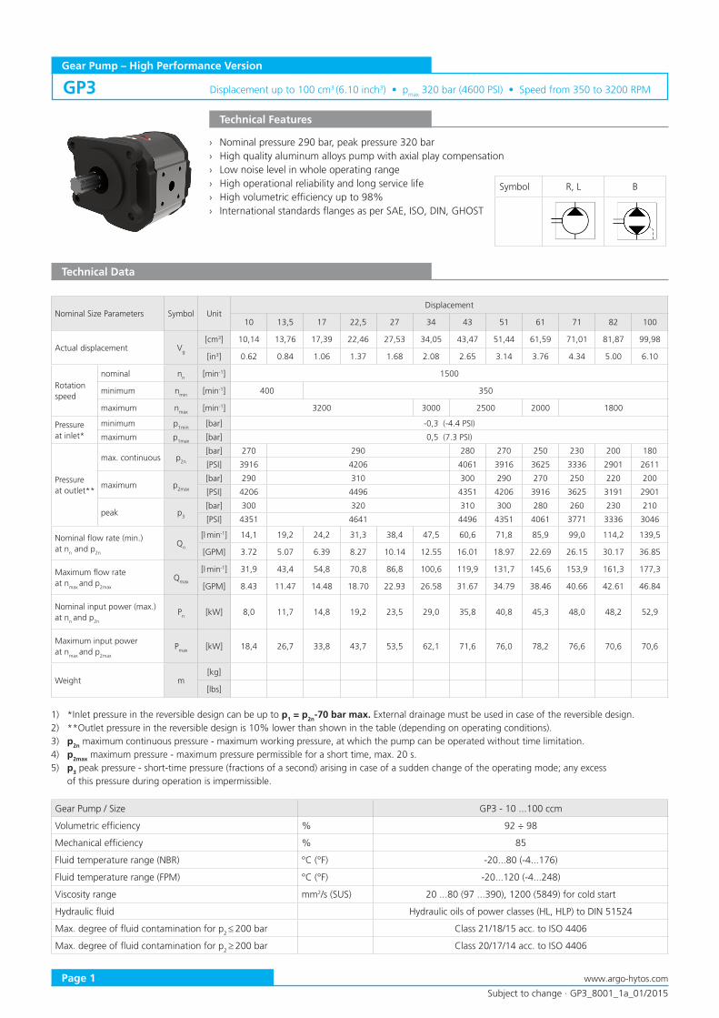
Gear Pump – High Performance Version
› Nominal pressure 290 bar, peak pressure 320 bar › High quality aluminum alloys pump with axial play compensation › Low noise level in whole operating range › High operational reliability and long service life › High volumetric efficiency up to 98% › International standards flanges as per SAE, ISO, DIN, GHOST
Technical Features
Nominal Size Parameters Symbol UnitDisplacement
10 13,5 17 22,5 27 34 43 51 61 71 82 100
Actual displacement Vg
[cm3] 10,14 13,76 17,39 22,46 27,53 34,05 43,47 51,44 61,59 71,01 81,87 99,98
[in3] 0.62 0.84 1.06 1.37 1.68 2.08 2.65 3.14 3.76 4.34 5.00 6.10
Rotation speed
nominal nn [min-1] 1500
minimum nmin [min-1] 400 350
maximum nmax [min-1] 3200 3000 2500 2000 1800
Pressure at inlet*
minimum p1min [bar] -0,3 (-4.4 PSI)
maximum p1max [bar] 0,5 (7.3 PSI)
Pressure at outlet**
max. continuous p2n
[bar] 270 290 280 270 250 230 200 180
[PSI] 3916 4206 4061 3916 3625 3336 2901 2611
maximum p2max
[bar] 290 310 300 290 270 250 220 200
[PSI] 4206 4496 4351 4206 3916 3625 3191 2901
peak p3
[bar] 300 320 310 300 280 260 230 210
[PSI] 4351 4641 4496 4351 4061 3771 3336 3046
Nominal flow rate (min.)at nn and p2n
Qn
[l.min-1] 14,1 19,2 24,2 31,3 38,4 47,5 60,6 71,8 85,9 99,0 114,2 139,5
[GPM] 3.72 5.07 6.39 8.27 10.14 12.55 16.01 18.97 22.69 26.15 30.17 36.85
Maximum flow rate at nmax and p2max
Qmax
[l.min-1] 31,9 43,4 54,8 70,8 86,8 100,6 119,9 131,7 145,6 153,9 161,3 177,3
[GPM] 8.43 11.47 14.48 18.70 22.93 26.58 31.67 34.79 38.46 40.66 42.61 46.84
Nominal input power (max.)at nn and p2n
Pn [kW] 8,0 11,7 14,8 19,2 23,5 29,0 35,8 40,8 45,3 48,0 48,2 52,9
Maximum input powerat nmax and p2max
Pmax [kW] 18,4 26,7 33,8 43,7 53,5 62,1 71,6 76,0 78,2 76,6 70,6 70,6
Weight m[kg]
[lbs]
Technical Data
1) *Inlet pressure in the reversible design can be up to p1 = p2n-70 bar max. External drainage must be used in case of the reversible design.2) **Outlet pressure in the reversible design is 10% lower than shown in the table (depending on operating conditions).3) p2n maximum continuous pressure - maximum working pressure, at which the pump can be operated without time limitation.4) p2max maximum pressure - maximum pressure permissible for a short time, max. 20 s.5) p3 peak pressure - short-time pressure (fractions of a second) arising in case of a sudden change of the operating mode; any excess of this pressure during operation is impermissible.
Gear Pump / Size GP3 - 10 ...100 ccm
Volumetric efficiency % 92 ÷ 98
Mechanical efficiency % 85
Fluid temperature range (NBR) °C (°F) -20...80 (-4...176)
Fluid temperature range (FPM) °C (°F) -20...120 (-4...248)
Viscosity range mm2/s (SUS) 20 ...80 (97 ...390), 1200 (5849) for cold start
Hydraulic fluid Hydraulic oils of power classes (HL, HLP) to DIN 51524
Max. degree of fluid contamination for p2 ≤ 200 bar Class 21/18/15 acc. to ISO 4406
Max. degree of fluid contamination for p2 ≥ 200 bar Class 20/17/14 acc. to ISO 4406
GP3
Symbol R, L B
Displacement up to 100 cm3 (6.10 inch3) • pmax 320 bar (4600 PSI) • Speed from 350 to 3200 RPM
Subject to change · GP3_8001_1a_01/2015
Page 2www.argo-hytos.com
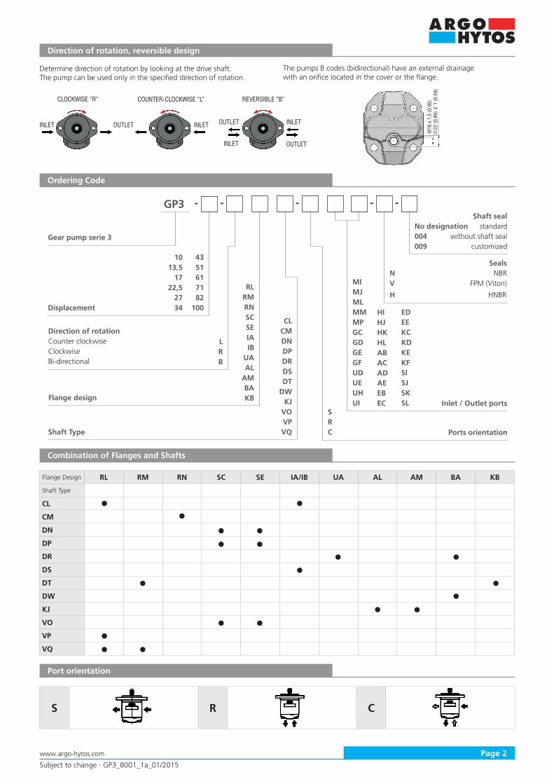
Direction of rotation, reversible design
Ordering Code
Determine direction of rotation by looking at the drive shaft.The pump can be used only in the specified direction of rotation.
The pumps B codes (bidirectional) have an external drainagewith an orifice located in the cover or the flange.
CLOCKWISE “R“ COUNTER-CLOCKWISE “L“ REVERSIBLE “B“
INLET OUTLET INLET
INLET
OUTLET
OUTLET
INLET
M16
x 1
,5 (0
.06)
22 (0
.89)
1
(0.0
4)
GP3
4351617182
100
- -- -
LRB
RLRMRNSCSEIAIB
UAAL
AMBAKB
CLCMDNDPDRDSDT
DWKJ
VOVPVQ
SRC
MIMJMLMMMPGCGDGEGFUDUEUHUI
HIHJHKHLABACADAEEBEC
EDEEKCKDKEKFSISJSKSL
Gear pump serie 3
Displacement
Ports orientation
Direction of rotation Counter clockwiseClockwiseBi-directional
Flange design
Shaft Type
SealsN NBRV FPM (Viton)
H HNBR
Inlet / Outlet ports
Combination of Flanges and Shafts
Flange Design RL RM RN SC SE IA/IB UA AL AM BA KB
Shaft Type
CL
CM
DN
DP
DR
DS
DT
DW
KJ
VO
VP
VQ
-
1013,5
1722,5
2734
S R C
Port orientation
No designation004009
Shaft sealstandard
without shaft sealcustomized
Subject to change · GP3_8001_1a_01/2015
Page 3 www.argo-hytos.com
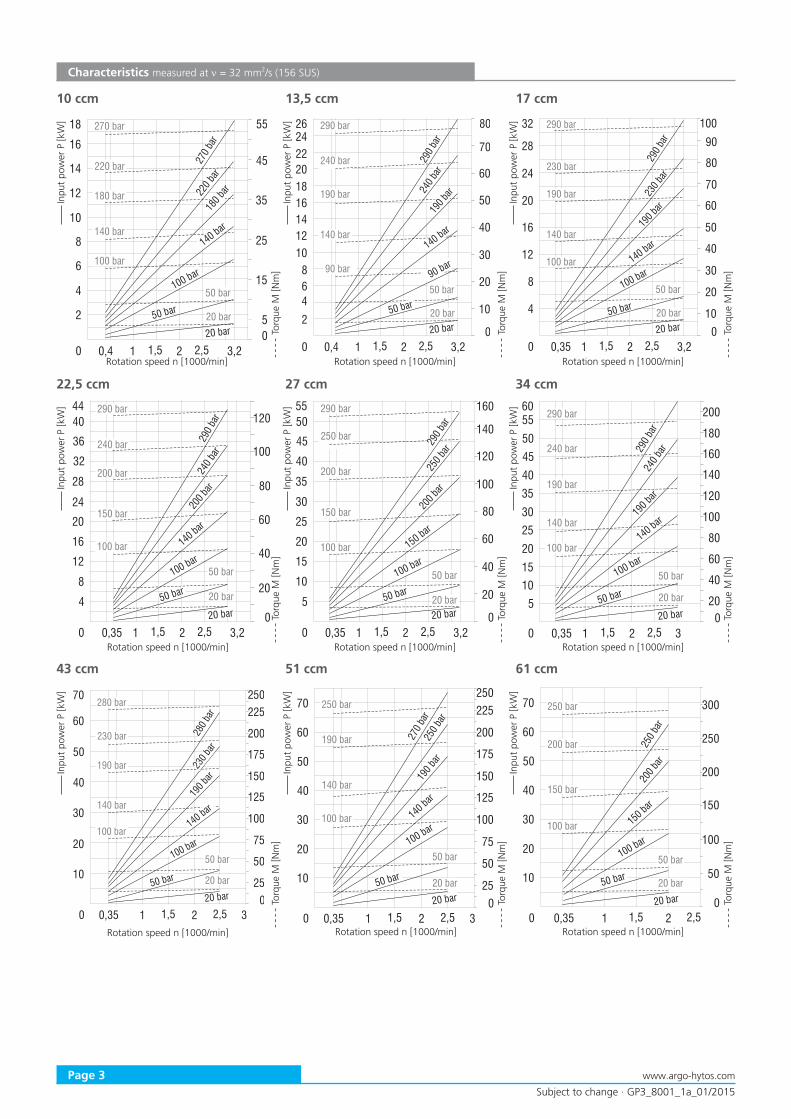
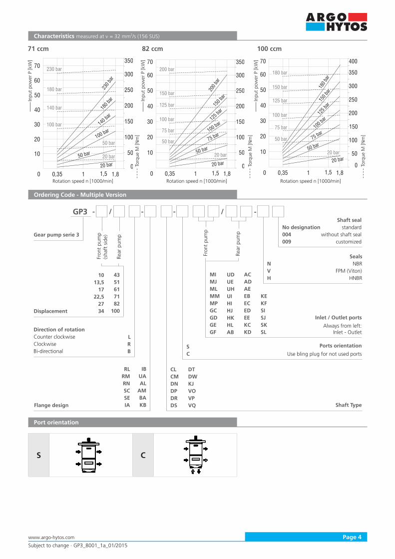
Characteristics measured at ν = 32 mm2/s (156 SUS) In
put
pow
er P
[kW
]
Rotation speed n [1000/min]
Tor
que
M [N
m]
Inpu
t po
wer
P [k
W]
Rotation speed n [1000/min]
Tor
que
M [N
m]
Inpu
t po
wer
P [k
W]
Rotation speed n [1000/min]
Tor
que
M [N
m]
Inpu
t po
wer
P [k
W]
Rotation speed n [1000/min]
Tor
que
M [N
m]
Inpu
t po
wer
P [k
W]
Rotation speed n [1000/min]
Tor
que
M [N
m]
Inpu
t po
wer
P [k
W]
Rotation speed n [1000/min]
Tor
que
M [N
m]
Inpu
t po
wer
P [k
W]
Rotation speed n [1000/min]
Tor
que
M [N
m]
Inpu
t po
wer
P [k
W]
Rotation speed n [1000/min]
Tor
que
M [N
m]
Inpu
t po
wer
P [k
W]
Rotation speed n [1000/min]
Tor
que
M [N
m]
61 ccm
10 ccm 13,5 ccm 17 ccm
22,5 ccm 27 ccm 34 ccm
43 ccm 51 ccm
16
0
5
15
0,4 3,20
180 bar12
1
220 bar
270 bar
10
2
35
100 bar
20 bar
25
50 bar
45
18
14
20 bar
55
50 bar4
6
8
21,5 2,5
140 bar
100 bar
140 bar
180 ba
r220 ba
r
270 ba
r
18
0
10
20
0,4 3,20
190 bar
12
1
240 bar
290 bar
10
2
60
20 bar
50
70
26
14
20 bar
80
50 bar468
21,5 2,5
140 bar
90 bar
240 ba
r29
0 bar
40
30
16
202224
190 ba
r
140 bar
90 bar
50 bar
0
10
20
0,35 3,20
190 bar
12
1
230 bar
290 bar
60
20 bar
50
70
32
20 bar
80
50 bar
4
8
21,5 2,5
140 bar
100 bar
230 ba
r29
0 bar
40
30
16
20
24
190 ba
r
140 bar
100 bar
50 bar
90100
28
0
20
0,35 3,20
200 bar28
1
240 bar
290 bar
60
20 bar
44
20 bar
80
50 bar
4
8
21,5 2,5
150 bar
100 bar
240 ba
r29
0 bar
40
32
36
200 ba
r
140 bar
100 bar
50 bar
12040
100
24
20
16
12
0
20
0,35 3,20
200 bar35
1
250 bar
290 bar
60
20 bar
55
20 bar
80
50 bar
5
21,5 2,5
150 bar
100 bar
250 b
ar
40
40
45
150 bar
100 bar
50 bar
16050
140
30
25
20
15
100
120
10
290 ba
r
200 ba
r
0
20
0,35 30
190 bar35
1
240 bar
290 bar
60
20 bar
60
20 bar
80
50 bar
5
21,5 2,5
140 bar
100 bar
40
4045
100 bar
50 bar
200
50 180
30252015
140
160
10
290 ba
r
190 ba
r
55
120
100
240 b
ar
140 bar
0
25
0,35 30
190 bar
1
230 bar
280 bar
75
20 bar
60
20 bar
50 bar
21,5 2,5
140 bar
100 bar
50
40
100 bar
50 bar
225
50
200
30
20
150
175
10
280 b
ar
125
100
70 250
140 bar
190 b
ar23
0 bar
0
25
0,35 30
190 bar
1
250 bar
75
20 bar
60
20 bar
50 bar
21,5 2,5
140 bar
100 bar
50
40
100 bar
50 bar
225
50
200
30
20
150
175
10
270 ba
r
125
100
70250
140 bar
190 b
ar25
0 bar
0 0,350
200 bar
1
250 bar
20 bar
60
20 bar
50 bar
21,5 2,5
150 bar
100 bar
50
40
100 bar
50 bar
50200
30
20
150
10
100
70 300
150 bar
200 b
ar25
0 bar
250
Subject to change · GP3_8001_1a_01/2015
Page 4www.argo-hytos.com
Ordering Code - Multiple Version
Port orientation
S C
Characteristics measured at ν = 32 mm2/s (156 SUS) In
put
pow
er P
[kW
]
Rotation speed n [1000/min]
Tor
que
M [N
m]
Inpu
t po
wer
P [k
W]
Rotation speed n [1000/min]
Tor
que
M [N
m]
Inpu
t po
wer
P [k
W]
Rotation speed n [1000/min]
Tor
que
M [N
m]
71 ccm 82 ccm 100 ccm
0 0,350
180 bar
1
230 bar
20 bar
60
20 bar
50 bar
1,81,5
140 bar
100 bar
50
40
100 bar
50 bar
50
200
30
20
150
10
100
70300
140 bar
180 ba
r23
0 bar
250
350
0 0,350
150 bar
1
200 bar
20 bar
60
20 bar
50 bar
1,81,5
125 bar
100 bar
50
40
50 bar
50
200
30
20
150
10
100
70
300
125 bar
200 b
ar
250
350
75 bar
150 ba
r
100 bar
75 bar
0 0,350
150 bar
1
180 bar
20 bar
60
20 bar
50 bar
1,81,5
125 bar
100 bar
50
40
50 bar
50
20030
20
150
10
100
70
300180 ba
r
250
400
75 bar
75 bar
350
150 b
ar
125 ba
r
100 bar
1013,5
1722,5
2734
4351617182
100
GP3
LRB
- -- -
CLCMDNDPDRDS
SC
Gear pump serie 3
Displacement
Ports orientation
Use bling plug for not used ports
Direction of rotation Counter clockwiseClockwiseBi-directional
Shaft Type
Inlet / Outlet ports
Always from left: Inlet - Outlet
Fron
t pu
mp
(sha
ft s
ide)
Rear
pum
p
IBUAAL
AMBAKBFlange design
RLRMRNSCSEIA
DTDWKJVOVPVQ
/ /Fr
ont
pum
p
Rear
pum
p
SealsN NBRV FPM (Viton)H HNBR
No designation004009
Shaft sealstandard
without shaft sealcustomized
MIMJMLMMMPGCGDGEGF
UDUEUHUIHIHJHKHLAB
ACADAEEBECEDEEKCKD
KEKFSISJSKSL
Subject to change · GP3_8001_1a_01/2015
Page 5 www.argo-hytos.com
118,5 (4.67)98,5 (3.88)
4x
11(0
.43)
21,8
(0.8
6)
5 (0.20)
50,8
(2.0
) f8
25 (0.98)
21,8
(0.8
6)
148
(5.8
3)12
8 (5
.04)
42,2
(1.6
6)123 (4.84)104 (4.09)
24,5
(0.9
6)
4x
11(0
.43)
5 (0.20)
70 (2
.76)
f8
[ ]28 (1.10)
162
(6.3
8)14
3 (5
.63)
71,5
(2.8
1)
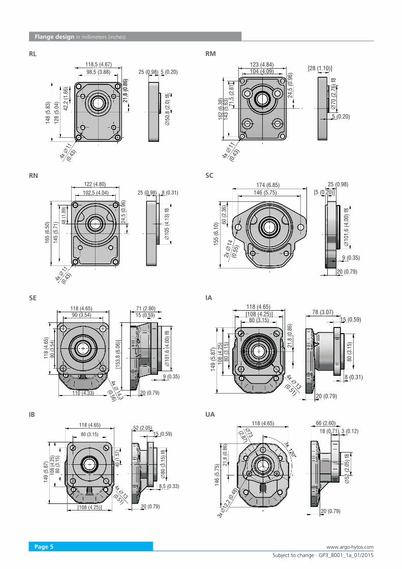
RL RM
Flange design in millimeters (inches)
122 (4.80)
102,5 (4.04)
24,5
(0.9
6)
4x
11(0.
43)
105
(4.1
3) f8
25 (0.98)
165
(6.5
0)14
5 (5
.71) 48
(1.8
9)
8 (0.31)174 (6.85)
146 (5.75)
2x14
(0.5
5)
10(4
.) f
81,
600
25 (0.98)
155
(6.1
0) 60 (2
.36)
[5 20 ](0. )
9 35(0. )
2 (0. )0 79
RN SC
118 4 6( . 5)90 3 54( . )
4,36
x 14(0.5)
10(4
.) f
81,
600
[153
,86
06]
(.
)
9 35(0. )
2 (0. )0 79
903
54(
.)
118
46
(.
5)
110 4 33( . )
71 2 80( . )15 0 59( . )
118 4 6( . 5)[108 4 25 ]( . )
x 13(0.51)4 8 (0. 1)3
2 (0. )0 79
78 (3.07)15 0 59( . )
108
425
(.
)14
9 (5
.87)
80 (3.15)
80 (3
.15) 21
,8 (0
.86)
80 (3
.15)
SE IA
118 4 6( . 5)
[108 4 25 ]( . )
x 13(0.51)4 8,5 (0. 3)3
2 (0. )0 79
52 (2.05)15 0 59( . )
108
425
(.
)14
9 (5
.87)
80 (3.15)
80 (3
.15)
40 (1
.57)
80 (3
.15)
f8
118 4 6( . 5)3 (0.12)
2 (0. )0 79
66 (2.60)18 ( .71)0
146
(5.7
5) 21,8
(0.8
6)
73
(2.87)
52 (2
.05)
f8
3x
12,2
(0.48
)
IB UA
Subject to change · GP3_8001_1a_01/2015
Page 6www.argo-hytos.com
134 (5.28)5 (0.20)
2 (0. )0 79
59 (2.32)13 ( .51)0
150,
7 (5
.93)
90 (3
.54)
f8
4x 11(0.43)
110 (4.33)
86 (3
.39)
114
(4.4
9)
160
(6.3
0)
123 (4.84)
4 (0.16)53 (2.09)13 ( .51)0
128
(5.0
4)
6x
11 (0
.43)
105
(4.1
3)
20,2 (0.80)
85 (3
.35)
f8
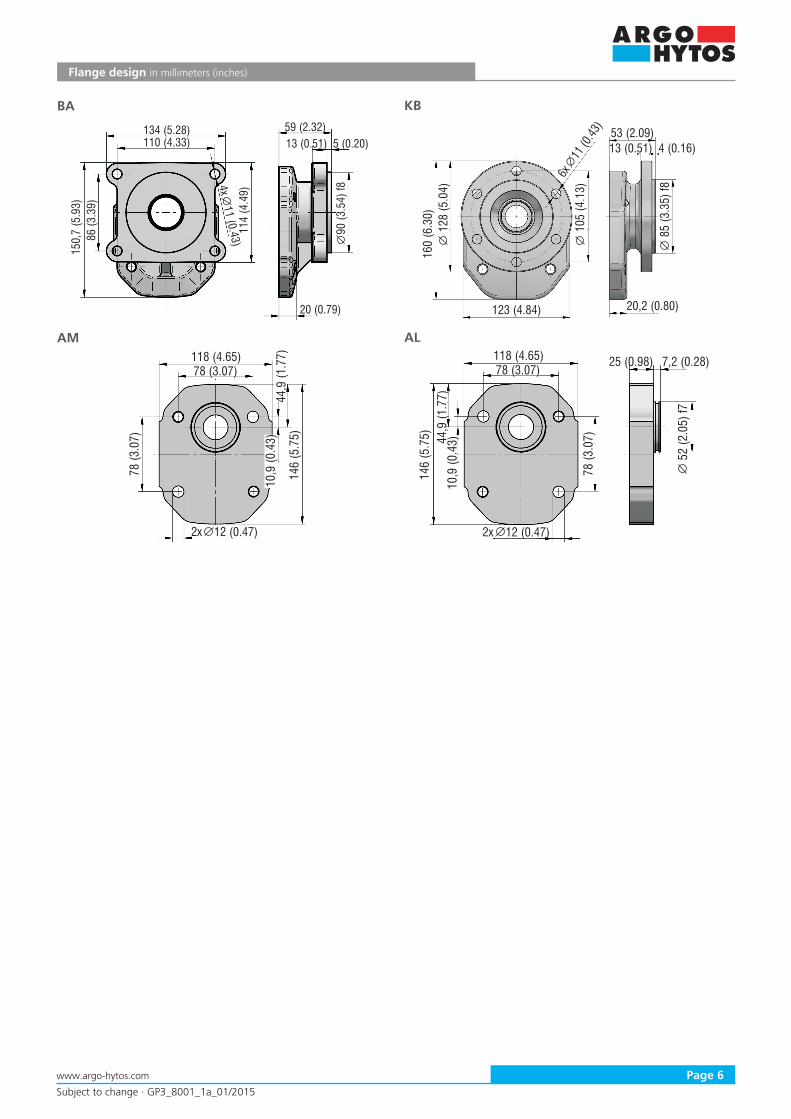
BA KB
Flange design in millimeters (inches)
118 (4.65)
146
(5.7
5)
2x 12 (0.47)
78 (3.07)
78 (3
.07)
10,9
(0.4
3)44
,9 (1
.77) 118 (4.65)
146
(5.7
5)
7,2 (0.28)25 ( .98)0
2x 12 (0.47)
78 (3.07)
44,9
(1.7
7)10
,9 (0
.43)
78 (3
.07)
52 (2
.05)
f7
AM AL
Subject to change · GP3_8001_1a_01/2015
Page 7 www.argo-hytos.com
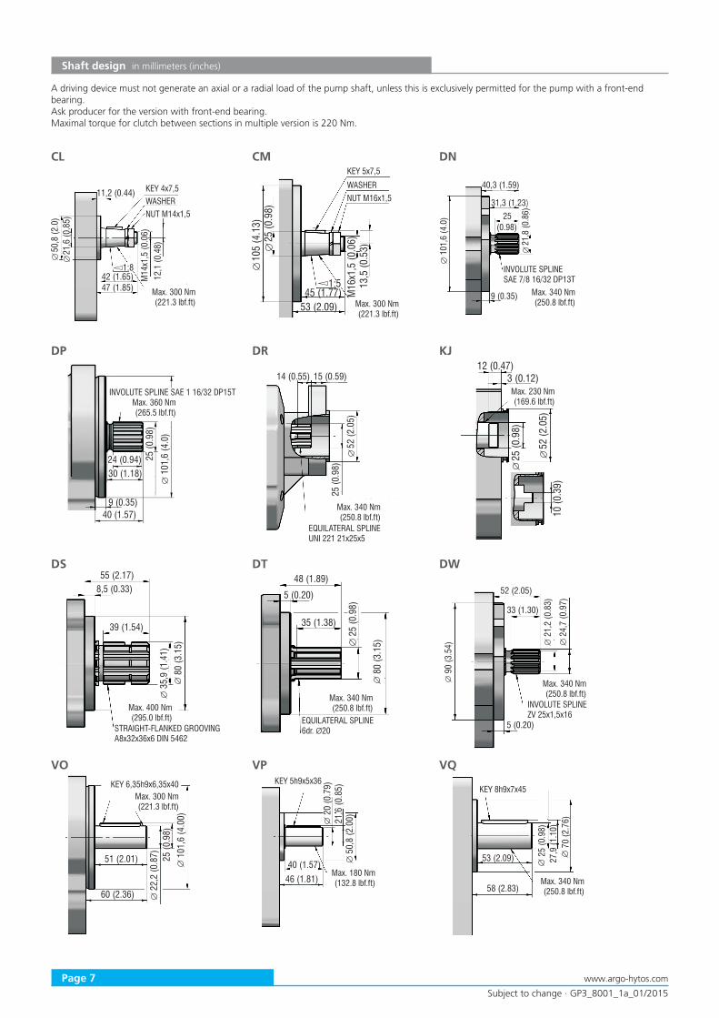
Shaft design in millimeters (inches)
11,2 (0.44)
50,8
(2.0
)21
,6 (0
.85)
42 (1.65)47 (1.85)
1:8
M14
x1,5
(0.0
6)12
,1 (0
.48)
105
(4.1
3)
1:5 13,5
(0.5
3)
25 (0
.98)
45 (1.77)53 (2.09)
M16
x1,5
(0.0
6)
40,3 (1.59)
101,
6 (4
.0) 25
(0.98)
31,3 (1.23)
21,8
(0.8
6)
9 (0.35)
CL CM DN
Max. 300 Nm (221.3 lbf.ft)
INVOLUTE SPLINESAE 7/8 16/32 DP13T
9 (0.35)
101,
6 (4
.0)
40 (1.57)
25 (0
.98)
30 (1.18)24 (0.94)
25 (0
.98)
52 (2
.05)
14 (0.55) 15 (0.59)12 (0.47)
52 (2
.05)
3 (0.12)
25 (0
.98)
10 (0
.39)
DP DR KJ
WASHERKEY 4x7,5
A driving device must not generate an axial or a radial load of the pump shaft, unless this is exclusively permitted for the pump with a front-end bearing.Ask producer for the version with front-end bearing.Maximal torque for clutch between sections in multiple version is 220 Nm.
NUT M14x1,5
KEY 5x7,5
WASHERNUT M16x1,5
EQUILATERAL SPLINEUNI 221 21x25x5
55 (2.17)8,5 (0.33)
80 (3
.15)
39 (1.54)
35,9
(1.4
1)
48 (1.89)
5 (0.20)
80 (3
.15)
35 (1.38)
25 (0
.98)
52 (2.05)
5 (0.20)
90 (3
.54)
33 (1.30)
21,2
(0.8
3)
24,7
(0.9
7)DS DT DW
INVOLUTE SPLINEZV 25x1,5x16
101,
6 (4
.00)
51 (2.01)
22,2
(0.8
7)
60 (2.36)
25 (0
.98)
20 (0
.79)
46 (1.81)
21,6
(0.8
5)50
,8 (2
.00)
40 (1.57)
70 (2
.76)
58 (2.83)
53 (2.09) 27,9
(1.1
0)25
(0.9
8)
VO VP VQ
INVOLUTE SPLINE SAE 1 16/32 DP15T
Max. 300 Nm (221.3 lbf.ft)
Max. 340 Nm (250.8 lbf.ft)
Max. 360 Nm (265.5 lbf.ft)
Max. 340 Nm (250.8 lbf.ft)
Max. 230 Nm (169.6 lbf.ft)
STRAIGHT-FLANKED GROOVINGA8x32x36x6 DIN 5462
Max. 400 Nm (295.0 lbf.ft) EQUILATERAL SPLINE
6dr. Ø20
Max. 340 Nm (250.8 lbf.ft)
Max. 340 Nm (250.8 lbf.ft)
Max. 300 Nm (221.3 lbf.ft)
KEY 6,35h9x6,35x40 KEY 5h9x5x36
Max. 180 Nm (132.8 lbf.ft)
KEY 8h9x7x45
Max. 340 Nm (250.8 lbf.ft)
Subject to change · GP3_8001_1a_01/2015
Page 8www.argo-hytos.com
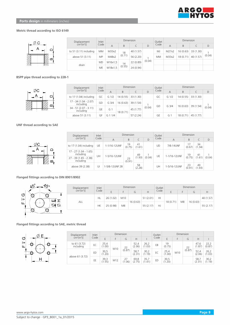
Ports design in millimeters (inches)
BSPP pipe thread according to 228-1
UNF thread according to SAE
Flanged fittings according to DIN 8901/8902
Flanged fittings according to SAE, metric thread
Displacementcm3(in3)]
Inlet Code
Dimension Outlet Code
Dimension
A B C D A B C D
to 51 (3.11) including MM M33x2 18 (0.71)
40 (1.57)
1 (0.04)
MJ M27x2 16 (0.63) 33 (1.30) 1 (0.04)above 51 (3.11) MP M48x2 56 (2.20) MM M33x2 18 (0.71) 40 (1.57)
drainMD M16x1,5 14
(0.55)
22 (0.89)
ME M18x1,5 24 (0.94)
Metric thread according to ISO 6149
Displacementcm3(in3)]
Inlet Code
Dimension Outlet Code
Dimension
A B C D A B C D
to 17 (1.04) including GC G 1/2 14 (0.55) 33 (1.30)
1 (0.04)
GC G 1/2 14 (0.55) 33 (1.30)
1 (0.04)
17 - 34 (1.04 - 2.07)including GD G 3/4 16 (0.63) 39 (1.54)
GD G 3/4 16 (0.63) 39 (1.54)34 - 51 (2.07 - 3.11)
including GE G 118 (0.71)
45 (1.77)
above 51 (3.11) GF G 1 1/4 57 (2.24) GE G 1 18 (0.71) 45 (1.77)
Displacementcm3(in3)]
Inlet Code
Dimension Outlet Code
Dimension
A B C D A B C D
to 17 (1.04) including UE 1-1/16-12UNF 19 (0.75)
41 (1.61)
1 (0.04)
UD 7/8-14UNF 17 (0.67)
34 (1.34)
1 (0.04)
17 - 27 (1.04 - 1.65)including
UH 1-5/16-12UNF23
(0.91)
49 (1.93) UE 1-1/16-12UNF 19
(0.75)41
(1.61)27 - 39 (1.65 - 2.38)including
above 39 (2.38) UI 1-5/8-12UNF 2B 58 (2.28) UH 1-5/16-12UNF 23
(0.91)49
(1.93)
Displacementcm3(in3)]
Inlet Code
Dimension Outlet Code
Dimension
E F G H E F G H
ALLHL 26 (1.02) M10
16 (0.63)51 (2.01) HI
18 (0.71) M8 16 (0.63)40 (1.57)
HK 25 (0.98) M8 55 (2.17) HJ 55 (2.17)
Displacementcm3(in3)]
Inlet Code
Dimension Outlet Code
Dimension
E F G H I E F G H I
to 61 (3.72)including EC 25,4
(1.00)M10 22
(0.87)
52,4 (2.06)
26,2 (1.03) EB 19
(0.75)
M10
22 (0.87)
47,6 (1.87)
22,2 (0.87)
above 61 (3.72)ED 30,5
(1.20)58,7
(2.31)30,2
(1.19) EC 25,4 (1.00)
52,4 (2.06)
26,2 (1.03)
EE 39,3 (1.55) M12 27
(1.06)69,8
(2.75)35,7
(1.41) ED 30,5 (1.20)
58,7 (2.31)
30,2 (1.19)
Subject to change · GP3_8001_1a_01/2015
Page 9 www.argo-hytos.com
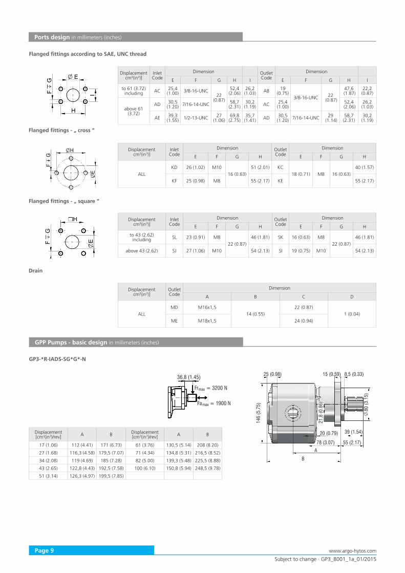
Ports design in millimeters (inches)
Flanged fittings - „ cross “
Flanged fittings according to SAE, UNC thread
Displacementcm3(in3)]
Inlet Code
Dimension Outlet Code
Dimension
E F G H E F G H
ALLKD 26 (1.02) M10
16 (0.63)51 (2.01) KC
18 (0.71) M8 16 (0.63)40 (1.57)
KF 25 (0.98) M8 55 (2.17) KE 55 (2.17)
Flanged fittings - „ square “
Displacementcm3(in3)]
Inlet Code
Dimension Outlet Code
Dimension
E F G H E F G H
to 43 (2.62)including SL 23 (0.91) M8
22 (0.87)46 (1.81) SK 16 (0.63) M8
22 (0.87)46 (1.81)
above 43 (2.62) SJ 27 (1.06) M10 54 (2.13) SI 19 (0.75) M10 54 (2.13)
Drain
Displacementcm3(in3)]
Outlet Code
Dimension
A B C D
ALLMD M16x1,5
14 (0.55)22 (0.87)
1 (0.04)ME M18x1,5 24 (0.94)
GPP Pumps - basic design in millimeters (inches)
Q
146
(5.7
5)
A
B
25 (0.98) 15 (0.59) 8,5 (0.33)
21,8
(0.8
6)
80 (3
.15)
39 (1.54)
55 (2.17)78 (3.07)
20 (0.79)
GP3-*R-IADS-SG*G*-N
Displacement[cm3(in3)/rev] A B Displacement
[cm3(in3)/rev] A B
17 (1.06) 112 (4.41) 171 (6.73) 61 (3.76) 130,5 (5.14) 208 (8.20)
27 (1.68) 116,3 (4.58) 179,5 (7.07) 71 (4.34) 134,8 (5.31) 216,5 (8.52)
34 (2.08) 119 (4.69) 185 (7.28) 82 (5.00) 139,3 (5.48) 225,5 (8.88)
43 (2.65) 122,8 (4.43) 192,5 (7.58) 100 (6.10) 150,8 (5.94) 248,5 (9.78)
51 (3.14) 126,3 (4.97) 199,5 (7.85)
36,8 (1.45)
Fr = 3200 Nmax
Fa = 1900 Nmax
Displacementcm3(in3)]
Inlet Code
Dimension Outlet Code
Dimension
E F G H I E F G H I
to 61 (3.72)including AC 25,4
(1.00) 3/8-16-UNC22
(0.87)
52,4 (2.06)
26,2 (1.03) AB 19
(0.75)3/8-16-UNC 22
(0.87)
47,6 (1.87)
22,2 (0.87)
above 61 (3.72)
AD 30,5 (1.20) 7/16-14-UNC 58,7
(2.31)30,2 (1.19) AC 25,4
(1.00)52,4
(2.06)26,2
(1.03)
AE 39,3 (1.55) 1/2-13-UNC 27
(1.06)69,8 (2.75)
35,7 (1.41) AD 30,5
(1.20) 7/16-14-UNC 29 (1.14)
58,7 (2.31)
30,2 (1.19)
Subject to change · GP3_8001_1a_01/2015
Page 10www.argo-hytos.com
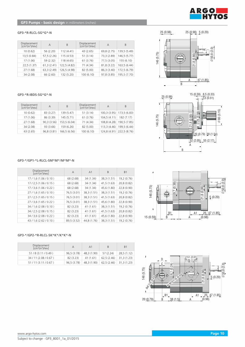
GP3 Pumps - basic design in millimeters (inches)
Q
146
(5.7
5)
A
B
25 (0.98)15 (0.59) 8,5 (0.33)
21,8
(0.8
6)
80 (3
.15)
55 (2.17)52 (2.05)
13 (0.51)
20 (0.79) 39 (1.54)
25 (0
.98)
GP3-*R-IBDS-SG*G*-N
Displacement[cm3(in3)/rev] A B Displacement
[cm3(in3)/rev] A B
10 (0.62) 83 (3.27) 139 (5.47) 51 (3.14) 100,3 (3.95) 173,5 (6.83)
17 (1.06) 86 (3.39) 145 (5.71) 61 (3.76) 104,5 (4.11) 182 (7.17)
27 (1.68) 90,3 (3.56) 153,5 (6.04) 71 (4.34) 108,8 (4.28) 190,5 (7.85)
34 (2.08) 93 (3.66) 159 (6.26) 82 (5.00) 113,3 (4.46) 199,5 (6.44)
43 (2.65) 96,8 (3.81) 166,5 (6.56) 100 (6.10) 124,8 (4.91) 222,5 (8.76)
146
(5.7
5)
Q
AB
25 (0.98)
47 (1.85)
25 (0.98) 5 (0.20)
21,8
(0.8
6)
50,8
(2.0
)
GP3-*R-RLCL-SG*G*-N
Displacement[cm3(in3)/rev] A B Displacement
[cm3(in3)/rev] A B
10 (0.62) 56 (2.20) 112 (4.41) 43 (2.65) 69,8 (2.75) 139,5 (5.49)
13,5 (0.84) 57,5 (2.26) 115 (4.53) 51 (3.14) 73,3 (2.89) 146,5 (5.77)
17 (1.06) 59 (2.32) 118 (4.65) 61 (3.76) 77,5 (3.05) 155 (6.10)
22,5 (1.37) 61,3 (2.41) 122,5 (4.82) 71 (4.34) 81,8 (3.22) 163,5 (6.44)
27 (1.68) 63,3 (2.49) 126,5 (4.98) 82 (5.00) 86,3 (3.40) 172,5 (6.79)
34 (2.08) 66 (2.60) 132 (5.20) 100 (6.10) 97,8 (3.85) 195,5 (7.70)
Q
146
(5.7
5)
AB25
(0.98)15 (0.59)
21,8
(0.8
6)
47 (1.85)
5 (0.20)
B1 A1
50,8
(2.0
)
9,7
(0.3
8)
GP3-*/GP1-*L-RLCL-SM*M*/M*M*-N
Displacement[cm3(in3)/rev] A A1 B B1
17 / 1,6 (1.06 / 0.10 ) 68 (2.68) 34 (1.34) 38,3 (1.51) 19,2 (0.76)
17 / 2,5 (1.06 / 0.15 ) 68 (2.68) 34 (1.34) 41,5 (1.63) 20,8 (0.82)
17 / 3,6 (1.06 / 0.22 ) 68 (2.68) 34 (1.34) 45,6 (1.80) 22,8 (0.90)
27 / 1,6 (1.65 / 0.10 ) 76,5 (3.01) 38,3 (1.51) 38,3 (1.51) 19,2 (0.76)
27 / 2,5 (1.65 / 0.15 ) 76,5 (3.01) 38,3 (1.51) 41,5 (1.63) 20,8 (0.82)
27 / 3,6 (1.65 / 0.22 ) 76,5 (3.01) 38,3 (1.51) 45,6 (1.80) 22,8 (0.90)
34 / 1,6 (2.08 / 0.10 ) 82 (3.23) 41 (1.61) 38,3 (1.51) 19,2 (0.76)
34 / 2,5 (2.08 / 0.15 ) 82 (3.23) 41 (1.61) 41,5 (1.63) 20,8 (0.82)
34 / 3,6 (2.08 / 0.22 ) 82 (3.23) 41 (1.61) 45,6 (1.80) 22,8 (0.90)
43 / 1,6 (2.62 / 0.10 ) 89,5 (3.52) 44,8 (1.76) 38,3 (1.51) 19,2 (0.76)
Q
146
(5.7
5)
AB 38 (1.5)
21,8
(0.8
6)
47 (1.85)
5 (0.20)
B1 A1
50,8
(2.0
)
6,1
(0.2
4)
20 (0.79)25
(0.98)
CD
4x M10
16 (0.63)
8xE
16 (0
.63)
26 (1.02)51 (2.01)
GP3-*/GP2-*R-RLCL-SK*K*/K*K*-N
Displacement[cm3(in3)/rev] A A1 B B1
51 / 8 (3.11 / 0.49 ) 96,5 (3.78) 48,3 (1.90) 57 (2.24) 28,5 (1.12)
34 / 11 (2.08 / 0.67 ) 82 (3.23) 41 (1.61) 62,5 (2.46) 31,3 (1.23)
51 / 11 (3.11 / 0.67 ) 96,5 (3.78) 48,3 (1.90) 62,5 (2.46) 31,3 (1.23)


![Directive 2014/68/UE – PED · torque (1) [Nm] Vs. pressure [bar] medium: water EPDM/NBR seat PTFE seat DN Kv [m 3/h] 3 bar 10 bar 16 bar 3 bar 6 bar 40 150 6 8 12 17 20 50 170 12](https://img.pdfslide.us/doc/110x75/5e9392da12d7521af708d281/directive-201468ue-a-torque-1-nm-vs-pressure-bar-medium-water-epdmnbr.jpg)