Embed Size (px)
Citation preview
Government of Canada Existing Building Renovation Issued for Tender 144202775.215 Edmonton, Alberta
June 8, 2016
Appendix No. 4 Specifications
GOVERNMENT OF CANADA
Existing Building Renovation Section 00 01 01
Edmonton, Alberta, Canada SPECIFICATION INDEX
Project No.: 144202775.215 Page 1 of 4
DIVISION 02 EXISTING CONDITIONS
Section 02 41 16 Selective Demolition ................................................................... 5 Section 02 83 33 Lead Abatement and Removal ..................................................... 9 Section 02 83 33.01 Initial Lead Surface Contamination Assessment ....................... 10
DIVISION 03 CONCRETE
Section 03 10 00 Concrete Forming and Accessories ........................................... 10 Section 03 20 00 Concrete Reinforcing ................................................................... 7 Section 03 30 00 Cast-in Place Concrete ............................................................... 15
DIVISION 04 MASONRY
Section 04 05 00 Common Work Results for Masonry ........................................... 8 Section 04 05 12 Masonry Mortar ........................................................................... 5 Section 04 05 19 Masonry Anchorage and Reinforcing .......................................... 5 Section 04 22 00 Concrete Unit Masonry ................................................................ 6
DIVISION 05 METALS
Section 05 50 00 Metal Fabrications ....................................................................... 9 Section 05 72 00 Stainless Steel Fabrications ......................................................... 5
DIVISION 06 WOOD, PLASTICS AND COMPOSITES
Section 06 10 00 Rough Carpentry .......................................................................... 5 Section 06 40 00 Architectural Woodwork ........................................................... 10
DIVISION 07 THERMAL AND MOISTURE PROTECTION
Section 07 21 16 Acoustic Insulation ...................................................................... 3 Section 07 84 00 Fire Stopping ............................................................................... 6 Section 07 92 00 Joint Sealing ................................................................................ 6
DIVISION 08 OPENINGS
Section 08 34 73 Acoustic Doors & Frames ............................................................ 8 Section 08 56 73 Sound Control Windows.............................................................. 6 Section 08 70 05 Cabinet and Miscellaneous Hardware ......................................... 4 Section 08 71 00 Door Hardware ............................................................................ 7 Section 08 81 00.01 Door Hardware Schedule ............................................................. 1
DIVISION 09 FINISHES
Section 09 21 16 Gypsum Board Assemblies ........................................................ 12 Section 09 51 13 Acoustic Ceilings ......................................................................... 7 Section 09 65 16 Resilient Flooring ........................................................................ 9 Section 09 67 10 Epoxy Flooring ............................................................................ 8 Section 09 91 23 Interior Painting ......................................................................... 12
GOVERNMENT OF CANADA
Existing Building Renovation Section 00 01 01
Edmonton, Alberta, Canada SPECIFICATION INDEX
Project No.: 144202775.215 Page 2 of 4
Section 09 91 23.01 Interior Re-Painting ................................................................... 11
DIVISION 11 EQUIPMENT
Section 11 67 23 Shooting Range Equipment ................................................... …..6 DIVISION 21 FIRE PROTECTION
Section 21 05 00 Common Work Results for Fire Suppression ................................... 2 Section 21 05 23 General Duty Valves for Water Based Fire Suppression Piping ...... 2 Section 21 05 29 Hangers and Supports for Fire Suppression Piping and Equipment ....................................................................... 2 Section 21 05 53 Identification for Fire Suppression Piping and Equipment .............. 2 Section 21 13 13 Wet Pipe Fire Suppression Sprinkler Systems ................................. 7 Section 21 13 19 Preaction Sprinkler Systems ............................................................. 9
DIVISION 22 PLUMBING
Section 22 01 10.51 Plumbing Piping Cleaning ................................................................ 3 Section 22 05 00 Common Work Results for Plumbing .............................................. 2 Section 22 05 19 Meters and Gauges for Plumbing Piping .......................................... 1 Section 22 05 23 General Duty Valves for Plumbing Piping ....................................... 6 Section 22 05 29 Hangers and Supports for Plumbing Piping and Equipment ............ 2 Section 22 05 53 Identification for Plumbing Piping and Equipment .......................... 2 Section 22 07 00 Plumbing Insulation .......................................................................... 2 Section 22 11 16 Domestic Water Piping ..................................................................... 6 Section 22 11 19 Domestic Water Piping Specialties ................................................... 3 Section 22 13 16 Sanitary Waste and Vent Piping ....................................................... 5 Section 22 13 19 Sanitary Waste Piping Specialties .................................................... 3 Section 22 15 13 General Service Compressed Air Piping .......................................... 2 Section 22 15 16 General Service Compressed Air Valves .......................................... 2 Section 22 15 19 General Service Packaged Air Compressors and Receivers ............. 2 Section 22 45 00 Emergency Plumbing Fixtures.......................................................... 2
DIVISION 23 HEATING, VENTILATION, AND AIR CONDITIONING (HVAC)
Section 23 01 30.51 HVAC Air Distribution System Cleaning ........................................ 4 Section 23 05 00 Common Work Results for HVAC ................................................. 34 Section 23 05 13 Common Motor Requirements for HVAC Equipment ..................... 8 Section 23 05 14 Variable Frequency Drives for HVAC Equipment ......................... 27 Section 23 05 19 Meters and Gauges for HVAC Systems ........................................... 5 Section 23 05 29 Hangers and Supports for HVAC Piping and Equipment .............. 14 Section 23 05 48 Vibration and Seismic Controls for HVAC .................................... 15 Section 23 05 53 Identification for HVAC Piping and Equipment ............................ 11 Section 23 05 93 Testing, Adjusting and Balancing for HVAC Systems .................. 13 Section 23 07 00 HVAC Insulation ............................................................................ 13 Section 23 09 00 Instrumentation and Control for HVAC ......................................... 15 Section 23 09 13 Instrumentation and Control Devices for HVAC ............................. 5 Section 23 09 23.6 Direct Digital Control Systems for HVAC –
GOVERNMENT OF CANADA
Existing Building Renovation Section 00 01 01
Edmonton, Alberta, Canada SPECIFICATION INDEX
Project No.: 144202775.215 Page 3 of 4
Input/Output Devices ........................................................................ 5 Section 23 09 93.1 Sequence of Operations for HVAC Control ..................................... 2 Section 23 09 93.2 Point Schedules ................................................................................. 1 Section 23 31 13 Metal Ducts ..................................................................................... 10 Section 23 33 00 Air Duct Accessories ........................................................................ 8 Section 23 34 00 HVAC Fans ...................................................................................... 4 Section 23 37 00 Air Outlets and Inlets ........................................................................ 3 Section 23 37 26 Laminar Airflow Airwall System ................................................... 10 Section 23 72 23 Packaged Air to Air Energy Recovery Units .................................... 5 Section 23 82 16 Air Coils ......................................................................... ……….3
DIVISION 26 ELECTRICAL
Section 26 05 00 11 Electrical General Requirements ............................................... 15 Section 26 05 19 00 Wires and Cables 0 - 1000 V ....................................................... 5 Section 26 05 19 10 Wire and Box Connectors 0 - 1000 V ......................................... 2 Section 26 05 19 11 Wiring Devices ............................................................................ 2 Section 26 05 29 00 Fastenings and Supports .............................................................. 4 Section 26 05 31 00 Splitters, Junction Boxes, Pull Boxes and Cabinets .................... 3 Section 26 05 32 00 Outlet Boxes, Conduit Boxes and Fittings................................... 4 Section 26 05 34 00 Conduits, Conduit Fastenings and Conduit Fittings .................... 6 Section 26 05 43 00 Direct Buried Underground Cable Ducts ..................................... 3 Section 26 05 43 10 Installation of cables in Trenches and in Ducts ........................... 2 Section 26 08 00 10 Starting of Electrical Equipment and System .............................. 2 Section 26 08 00 11 Testing, Adjusting and Balancing of Electrical Equipment and
Systems ........................................................................................ 4 Section 26 24 02 10 Disconnect Switches Fused and Non-Fused up to 600 V - Primary ............................................... 2 Section 26 24 16 00 Panelboard – Breaker Type ......................................................... 3 Section 26 24 16 01 Panelboards .................................................................................. 4 Section 26 24 16 10 Molded Case Circuit Breakers ..................................................... 2 Section 26 24 19 22 Motor Starts to 600V .................................................................. 5 Section 26 24 19 23 Connections to Mechanical Equipment ...................................... 2 Section 26 50 00 00 Lighting Equipment ..................................................................... 8 Section 26 53 00 00 Exit Lights ................................................................................... 1
DIVISION 27 COMMUNICATIONS
Section 27 10 05 00 Structured Cabling ..................................................................... 11 Section 27 10 05 10 Telecommunications Raceway System ........................................ 1
DIVISION 28 ELECTRONIC SAFETY AND SECURITY
Section 28 31 02 Addressable Fire Alarm System ................................................ 10
END OF SPECIFICATION INDEX
GOVERNMENT OF CANADA
Existing Building Renovation Section 02 41 16
Alberta, Canada SELECTIVE DEMOLITION
Project No.: 144202775.215 Page 1 of 5
1 General
1.1 RELATED SECTIONS
.1 Section 02 83 33 - Lead Abatement & Removal.
1.2 REFERENCES
.1 Definitions:
.1 Hazardous Materials: dangerous substances, dangerous goods, hazardous
commodities and hazardous products, include but not limited to: poisons,
corrosive agents, flammable substances, ammunition, explosives, radioactive
substances, or materials that endanger human health or environment if handled
improperly.
.2 Reference Standards:
.1 CSA International
.1 CSA S350-M1980(R2003), Code of Practice for Safety in Demolition of
Structures.
.2 Department of Justice Canada (Jus)
.1 Canadian Environmental Assessment Act (CEAA), 1995, c. 37.
.2 Canadian Environmental Protection Act (CEPA), 1999, c. 33.
.1 SOR/2003-2, On-Road Vehicle and Engine Emission
Regulations.
.2 SOR/2006-268, Regulations Amending the On-Road Vehicle and
Engine Emission Regulations.
.3 Transportation of Dangerous Goods Act (TDGA), 1992, c. 34.
1.3 ADMINISTRATIVE REQUIREMENTS
.1 Pre-Installation Meetings:
.1 Convene pre-installation meeting one week prior to beginning work of this
Section, with Contractor's Representative, Departmental Representative in
accordance with Section 01 31 19 - Project Meetings to:
.1 Verify project requirements.
.2 Verify existing site conditions adjacent to demolition work.
.3 Co-ordination with other construction subtrades.
.2 Hold project meetings every month.
.3 Ensure key personnel, site supervisor, project manager, subcontractor
representatives attend.
.4 Departmental Representative will provide written notification of change to
meeting schedule established upon contract award 24 hours prior to scheduled
meeting.
GOVERNMENT OF CANADA
Existing Building Renovation Section 02 41 16
Alberta, Canada SELECTIVE DEMOLITION
Project No.: 144202775.215 Page 2 of 5
.2 Scheduling:
.1 Employ necessary means to meet project time lines without compromising
specified minimum rates of material diversion.
.1 In event of unforeseen delay notify Departmental Representative in
writing.
.3 For demolition and range cleaning work, submit copies of Contractor’s qualifications as
follows:
.1 Respiratory Protection Program endorsed by a Certified Industrial Hygienist.
.2 Medical Surveillance Program.
.3 Evidence of medical examinations for all workers, including a physician's
statement indicating the employee is fit to conduct this type of work.
.4 Certificates of worker training
.5 Reference list demonstrating at least 10 previous projects of similar scope and a
minimum of five years' experience in this type of work.
1.4 QUALITY ASSURANCE
.1 Regulatory Requirements: Ensure Work is performed in compliance with applicable
Provincial and Municipal regulations.
.2 Comply with all applicable hygenic regulations governing shooting range cleaning.
1.5 SITE CONDITIONS
.1 Environmental protection:
.1 Ensure Work is done in accordance with Section 01 35 43 - Environmental
Procedures.
.2 Ensure Work does not adversely affect adjacent watercourses, groundwater and
wildlife, or contribute to excess air and noise pollution.
.3 Fires and burning of waste or materials is not permitted on site.
.4 Do not bury rubbish waste materials.
.5 Do not dispose of waste or volatile materials including but not limited to: mineral
spirits, oil, petroleum based lubricants, or toxic cleaning solutions into
watercourses, storm or sanitary sewers.
.1 Ensure proper disposal procedures are maintained throughout project.
.6 Do not pump water containing suspended materials into watercourses, storm or
sanitary sewers, or onto adjacent properties.
.7 Control disposal or runoff of water containing suspended materials or other
harmful substances in accordance with authorities having jurisdiction and as
directed by Departmental Representative.
.8 Protect trees, plants and foliage on site and adjacent properties where indicated.
.9 Prevent extraneous materials from contaminating air beyond application area, by
providing temporary enclosures during demolition work.
.10 Cover or wet down dry materials and waste to prevent blowing dust and debris.
Control dust on all temporary roads.
GOVERNMENT OF CANADA
Existing Building Renovation Section 02 41 16
Alberta, Canada SELECTIVE DEMOLITION
Project No.: 144202775.215 Page 3 of 5
.2 Where exterior demolition occurs, such as removal of roof top units and the like, take into
consideration, prevailing weather conditions and weather forecasts. Do not proceed with
demolition work when weather conditions constitute a hazard to the workers and site.
1.6 EXISTING CONDITIONS
.1 If material resembling spray or trowel applied asbestos or other substance listed as
hazardous be encountered in course of demolition, stop work, take preventative measures,
and notify Departmental Representative immediately. Proceed only after receipt of written
instructions have been received from Departmental Representative.
.2 Structures to be demolished are based on their condition at time of examination prior to
tendering.
.1 Remove, protect and store salvaged items as directed by Departmental
Representative. Salvage items as identified by Departmental Representative.
Deliver to Departmental Representative as directed.
2 Products
2.1 EQUIPMENT
.1 Leave machinery running only while in use, except where extreme temperatures prohibit
shutting machinery down.
2.2 SALVAGED MATERIALS
.1 In addition to the items noted as being salvaged for turn over to the Departmental
Representative or salvaged for reuse in this project, all existing items which are to be
removed or demolished, are to be inspected by the Departmental Representative. If the
Departmental Representative wants the demolished or removed items, turn them over to
the Departmental Representative. If the Departmental Representative does not want the
demolished or removed items, then they become the property of the Contractor and are to
be immediately removed from site.
.2 Notify the Departmental Representative prior to removal and obtain approval regarding
method of removal.
.3 Carefully remove without damage, items to be retained by the Departmental
Representative, or to be retained for reincorporation in the Work, and if required to ensure
reinstallation in the correct location, tag them to identify location of origin.
.4 Deliver and store where directed by the Departmental Representative, on site.
GOVERNMENT OF CANADA
Existing Building Renovation Section 02 41 16
Alberta, Canada SELECTIVE DEMOLITION
Project No.: 144202775.215 Page 4 of 5
3 Execution
3.1 PREPARATION
.1 Protection of in-place conditions:
.1 Work in accordance with Section 01 35 43 - Environmental Procedures.
.2 Prevent movement, settlement or damage of adjacent structures, services, and
parts of existing building to remain.
.1 Provide bracing, shoring and underpinning as required.
.2 Repair damage caused by demolition as directed by Departmental
Representative.
.3 Support affected structures and, if safety of structure being demolished adjacent
structures, services or parts or existing building to remain appears to be
endangered, take preventative measures, stop Work and immediately notify
Departmental Representative.
.4 Prevent debris from blocking surface drainage system, mechanical and electrical
systems which must remain in operation.
.2 Surface Preparation:
.1 Disconnect and re-route electrical and telephone service lines as required to
accommodate work.
.1 Post warning signs on electrical lines and equipment which must remain
energized to serve other properties during period of demolition.
.2 Disconnect and cap designated mechanical services.
.1 Natural gas supply lines: remove in accordance with gas company
requirements.
.2 Sewer and water lines: remove in accordance with authority having
jurisdiction and as directed by Departmental Representative.
.3 Other underground services: remove and dispose of as indicated.
.3 Do not disrupt active or energized utilities designated to remain undisturbed.
3.2 DEMOLITION
.1 Do demolition work in accordance with Section 01 56 00 - Temporary Barriers and
Enclosures.
.2 Blasting operations not permitted during demolition.
.3 Remove contaminated or dangerous materials as defined by authorities having jurisdiction,
relating to environmental protection, from site and dispose of in safe manner to minimize
danger at site or during disposal.
.4 Demolish parts of existing building as required to accommodate new construction.
.5 Crush concrete generated due to demolition of foundations to size suitable for recycling.
GOVERNMENT OF CANADA
Existing Building Renovation Section 02 41 16
Alberta, Canada SELECTIVE DEMOLITION
Project No.: 144202775.215 Page 5 of 5
.6 Remove existing equipment, services, and obstacles where required for refinishing or
making good of existing surfaces, and replace as work progresses.
.7 At end of each day's work, leave Work in safe and stable condition.
.1 Protect interiors of parts not to be demolished from exterior elements at all times.
.8 Demolish to minimize dusting. Keep materials wetted as directed by Departmental
Representative.
.9 Contain fibrous materials to minimize release of airborne fibres while being transported
within facility.
.10 Remove and dispose of demolished materials except where noted otherwise and in
accordance with authorities having jurisdiction.
.11 Immediately as demolition progresses, repair any resulting damage to existing parts
intended to remain.
.12 Use natural lighting to do Work where possible.
.1 Shut off lighting except those required for security purposes at end of each day.
3.3 CLEANING
.1 Designate appropriate security resources / measures to prevent vandalism, damage and
theft.
.2 Locate stockpiled materials convenient for use in new construction. Eliminate double
handling wherever possible.
.3 Remove demolition debris which is not otherwise to be salvaged, from site and dispose of
in a legal manner.
END OF SECTION

GOVERNMENT OF CANADA
Existing Building Renovation Section 02 83 33
Alberta, Canada LEAD ABATEMENT AND REMOVAL
Project No.: 144202775.215 Page 1 of 9
1 General
1.1 SUMMARY
.1 Comply with requirements of this Section when performing following Work:
.1 Removal/cleaning of lead-containing dust from all surfaces throughout rooms and
areas to be impacted by HVAC upgrade project
1.2 RELATED REQUIREMENTS
.1 Section 01 14 00 - Work Restrictions.
.2 Section 01 35 29.06 - Health and Safety Requirements
1.3 REFERENCES
.1 All applicable national building codes, Canadian electrical codes and standards, fire and
construction safety codes, shall be in effect during all aspects of this lead remediation
project. In any situation where there are discrepancies between these specifications and
others, the more stringent standard shall always apply. The following list has been
included as a guide only; others may apply:
.1 Canadian Environmental Protection Act,1999 (CEPA 1999)
.1 Export and Import of Hazardous Waste and Hazardous Recyclable Material
Regulations (SOR/2005-149).
.2 Department of Justice Canada (Jus)
.1 Transportation of Dangerous Goods Act, 1992 (TDG Act) [1992], (c. 34).
.2 Transportation of Dangerous Goods Regulations (T-19.01-SOR/2001-286).
.3 Health Canada / Workplace Hazardous Materials Information System (WHMIS)
.1 Material Safety Data Sheets (MSDS).
.4 National Research Council Canada Institute for Research in Construction (NRC-
IRC)
.1 National Fire Code of Canada-[2005].
.5 Alberta Government
.1 Alberta Occupational Health and Safety Act, Regulations and Code (AB
OH&S Reg., including amendments to date of work)
.2 “Alberta User Guide for Waste Managers”, current version
.3 Dangerous Goods Transportation and Handling Act
.6 The Federal Transportation of Dangerous Goods Regulation
1.4 RESTRICTIONS
.1 HEPA vacuum: High Efficiency Particulate Air filtered vacuum equipment with filter
system capable of collecting and retaining fibres greater than 0.3 microns in any direction
at 99.97% efficiency.
.2 Authorized Visitors: Departmental Representativeor designated representative[s] and
representatives of regulatory agencies.
.3 Occupied Area: areas of building or work site that is outside Work Area.
GOVERNMENT OF CANADA
Existing Building Renovation Section 02 83 33
Alberta, Canada LEAD ABATEMENT AND REMOVAL
Project No.: 144202775.215 Page 2 of 9
.4 Sprayer: garden reservoir type sprayer or airless spray equipment capable of producing
mist or fine spray. Must be appropriate capacity for scope of work.
.5 Airlock: ingress or egress system, without permitting air movement between contaminated
area and uncontaminated area. Consisting of two curtained doorways at least 2 m apart.
.6 Curtained doorway: arrangement of closures to allow ingress and egress from one room to
another. Typically constructed as follows:
.1 Place two overlapping polyethylene sheets over existing or temporarily framed
doorway, securing each along top of doorway, securing vertical edge of one sheet
along one vertical side of doorway, and secure other sheet along opposite vertical
side of doorway.
.2 Reinforce free edges of polyethylene with duct tape and add weight to bottom
edge to ensure proper closing.
.3 Overlap each polyethylene sheet at openings 1.5 m on each side.
.7 Action level: employee exposure, without regard to usage of respirators, to an airborne
concentration of lead of 50% of the 8 hour time-weighted average (TWA) occupational
exposure limit (OEL). TWA OEL for lead in Alberta is 0.05 milligrams per cubic meter of
air. Intermediate precautions for lead abatement are based on expected airborne lead
concentrations greater than 50% of the OEL (> 0.025 milligrams per cubic meter of air)
within Work Area.
.8 Competent person: individuals capable of identifying existing lead hazards in workplace
and taking corrective measures to eliminate them.
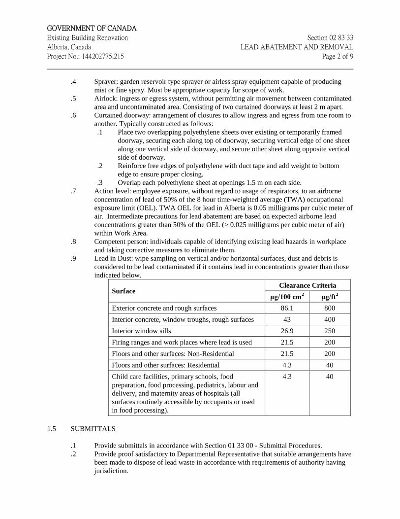
.9 Lead in Dust: wipe sampling on vertical and/or horizontal surfaces, dust and debris is
considered to be lead contaminated if it contains lead in concentrations greater than those
indicated below.
Surface Clearance Criteria
μg/100 cm2 μg/ft
2
Exterior concrete and rough surfaces 86.1 800
Interior concrete, window troughs, rough surfaces 43 400
Interior window sills 26.9 250
Firing ranges and work places where lead is used 21.5 200
Floors and other surfaces: Non-Residential 21.5 200
Floors and other surfaces: Residential 4.3 40
Child care facilities, primary schools, food
preparation, food processing, pediatrics, labour and
delivery, and maternity areas of hospitals (all
surfaces routinely accessible by occupants or used
in food processing).
4.3 40
1.5 SUBMITTALS
.1 Provide submittals in accordance with Section 01 33 00 - Submittal Procedures.
.2 Provide proof satisfactory to Departmental Representative that suitable arrangements have
been made to dispose of lead waste in accordance with requirements of authority having
jurisdiction.
GOVERNMENT OF CANADA
Existing Building Renovation Section 02 83 33
Alberta, Canada LEAD ABATEMENT AND REMOVAL
Project No.: 144202775.215 Page 3 of 9
.3 Provide Provincial requirements for Notice of Project Form, and provide a copy to the
Departmental Representative.
.4 Provide proof of Contractor's General and Environmental Liability Insurance.
.5 Quality Control:
.1 Provide Departmental Representative copies of necessary permits for
transportation and disposal of lead waste and proof that it has been received and
properly disposed.
.2 Provide proof satisfactory to Departmental Representative that employees have
had instruction on hazards of lead exposure, respirator use, dress, entry and exit
from Work Area, and aspects of work procedures and protective measures.
Minimum of one supervisor for every ten workers.
.3 Provide proof (certificates) that all equipment equipped with HEPA filters have
been DOP tested on-site.
.6 Product data:
.1 Provide documentation including Material Safety Data Sheets (MSDS) for
chemicals or materials that the contractor wishes to use on-site, including, but not
limited to:
.1 Encapsulants.
.2 Amended water.
.3 Slow drying sealer.
1.6 QUALITY ASSURANCE
.1 Regulatory Requirements: comply with Federal, Provincial/Territorial and local
requirements pertaining to lead paint, in case of conflict among those requirements or with
these specifications more stringent requirement applies. Comply with regulations in effect
at time work is performed.
.2 Health and Safety:
.1 Do construction occupational health and safety in accordance with Section
01 35 29.06 - Health and Safety Requirements.
.2 Safety Requirements: worker and visitor protection.
.1 Protective equipment and clothing to be worn by workers and visitors in
Work Area includes:
.1 Properly fitted NIOSH approved respirator equipped with HEPA or P-
100 filter cartridges with minimum assigned protection factor of 10
(half-mask or greater protection), acceptable to Authority having
jurisdiction. Suitable for type of lead and level of lead dust exposure in
Lead Work Area. Provide sufficient filters so workers can install new
filters following disposal of used filters and before re-entering
contaminated areas.
.2 Disposable type protective clothing that does not readily retain or
permit skin contamination, consisting of full body covering including
head covering with snug fitting cuffs at wrists, ankles, and neck.
.3 Steel Toe safety boots (CSA approved)
.2 Requirements for workers:
.1 Remove street clothes in clean change room and put on respirator with
new filters or reusable filters, clean coveralls and head covers before
entering Equipment and Access Rooms or Work Area. Store street
GOVERNMENT OF CANADA
Existing Building Renovation Section 02 83 33
Alberta, Canada LEAD ABATEMENT AND REMOVAL
Project No.: 144202775.215 Page 4 of 9
clothes, uncontaminated footwear, towels, and similar uncontaminated
articles in clean change room.
.2 Remove gross contamination from clothing before leaving work area.
Place contaminated work suits in receptacles for disposal with other
lead - contaminated materials. Leave reusable items except respirator
in Equipment and Access Room. When not in use in Work Area, store
work footwear in Equipment and Access Room. Upon completion of
lead abatement, dispose of footwear as contaminated waste or clean
thoroughly inside and out using soap and water before removing from
Work Area or from Equipment and Access Room.
.3 Enter unloading room from outside dressed in clean coveralls to
remove waste containers and equipment from Holding Room of
Container and Equipment Decontamination Enclosure system.
Workers not to use this system as means to leave or enter work area.
.3 Eating, drinking, chewing, and smoking are not permitted in Work Area.
.4 Ensure workers are fully protected with respirators and protective clothing
during preparation of system of enclosures prior to commencing actual lead
abatement.
.5 Ensure workers wash hands and face when leaving Work Area.
.6 Provide and post in Clean Change Room and in Equipment and Access
Room the procedures described in this Section, in both official languages.
.7 Ensure no person required to enter Work Area has facial hair that affects
seal between respirator and face.
.8 Visitor Protection:
.1 Provide protective clothing and approved respirators to Authorized
Visitors to Work Areas.
.2 Instruct Authorized Visitors in use of protective clothing, respirators
and procedures.
.3 Instruct Authorized Visitors in proper procedures to be followed in
entering into and exiting from Work Area.
1.7 WASTE AND MANAGEMENT AND DISPOSAL
.1 Separate waste materials for reuse and recycling in accordance with local municipal
bylaws.
.2 Handle and dispose of hazardous materials in accordance with CEPA, TDGA, Regional
and Municipal regulations.
.3 Disposal of lead waste generated by removal activities must comply with Federal,
Provincial and Municipal regulations. Dispose of lead waste in sealed double thickness 6
mil bags or leak proof drums, or as required by the accepting facility/transportation
regulations. Label containers with appropriate warning labels.
.4 Provide manifests describing and listing waste created. Transport containers by approved
means to licensed accepting facility.
1.8 EXISTING CONDITIONS
.1 Reports and information pertaining to assessment findings related to lead contamination
(and other hazardous building materials in the work area, where applicable) that is to be
GOVERNMENT OF CANADA
Existing Building Renovation Section 02 83 33
Alberta, Canada LEAD ABATEMENT AND REMOVAL
Project No.: 144202775.215 Page 5 of 9
removed, or otherwise disturbed and disposed of during this Project are attached to this
specification package in Appendix X.
.2 Notify Departmental Representative of lead contamination or other potential hazardous
building materials discovered during Work and not apparent from drawings,
specifications, or report pertaining to Work. Do not disturb such material until instructed
by Departmental Representative.
1.1 SCHEDULING
.1 Not later than two days before beginning Work on this Project notify the following in
writing, where appropriate:
.1 Provincial Ministry of Labour.
.2 Disposal Authority.
.2 Inform sub trades of presence of lead-containing materials identified in Existing
Conditions.
.3 Provide Departmental Representative with copies of notifications prior to start of Work.
.4 Hours of Work: perform work involving lead abatement during normal working hours.
2 Products
2.1 MATERIALS
.1 Polyethylene: 6 mil unless otherwise specified; in sheet size to minimize joints.
.2 FR polyethylene: 10 mil woven fibre reinforced fabric bonded both sides with
polyethylene.
.3 Tape: fibreglass - reinforced duct tape suitable for sealing polyethylene under dry
conditions and wet conditions using amended water.
.4 Slow - drying sealer: non-staining, clear, water - dispersible type that remains tacky on
surface for at least 8 hours and designed for trapping residual lead paint residue.
.5 Lead waste containers: All lead waste is to be placed in small means of containment which
meet the requirements for transporting leachable toxic waste, in accordance with
government regulations. All packaged waste is to be appropriately labeled and handled in
accordance with government regulations.
.6 Label containers with pre-printed bilingual cautionary labels indicating “Warning Lead”
clearly visible when ready for removal to disposal site.
3 Execution
3.1 SUPERVISION
.1 Approved Supervisor must remain within Lead Work Area during disturbance, removal,
or other handling of lead contamination.
3.1 PREPARATION
.1 Remove and wrap items to be salvaged or reused, and transport and store in area specified
by Departmental Representative.
.2 Work Area:
GOVERNMENT OF CANADA
Existing Building Renovation Section 02 83 33
Alberta, Canada LEAD ABATEMENT AND REMOVAL
Project No.: 144202775.215 Page 6 of 9
.1 Shut off and isolate HVAC system to prevent dust dispersal into other building
areas. Conduct smoke tests to ensure duct work is airtight.
.2 Pre-clean fixed casework, and equipment within work areas, using HEPA vacuum
and cover with polyethylene sheeting sealed with tape.
.3 Clean work areas using HEPA vacuum. If not practicable, use wet cleaning
method. Do not use methods that raise dust, such as dry sweeping, or vacuuming
using other than HEPA vacuum.
.4 Seal off openings, corridors, doorways, windows, skylights, ducts, grilles, and
diffusers, with polyethylene sheeting sealed with tape.
.5 Prevent the spread of dust from the Contact Work Area using measures
appropriate to the work to be done and which are consistent with the requirements
for a lead abatement operation. Erect a polyethylene enclosure around the
Contract Work Area.
.6 Establish negative pressure in polyethylene enclosure as follows:
.1 Install and maintain HEPA filtered Negative Air Unit(s) sufficient to
allow one complete air change every 15 minutes; and,
.2 Operate Negative Air Unit(s) continuously from time of Departmental
Representative’s authorization to proceed until acceptable clearance
results have been achieved and have been verified in writing by the
Departmental Representative.
.7 At point of access to work areas install warning signs in both official languages in
upper case "Helvetica Medium" letters reading as follows where number in
parentheses indicates font size to be used:
.1 CAUTION LEAD HAZARD AREA (25 mm).
.2 NO UNAUTHORIZED ENTRY (19 mm).
.3 WEAR ASSIGNED PROTECTIVE EQUIPMENT AND
RESPIRATOR (19 mm).
.4 BREATHING LEAD CONTAMINATED DUST CAUSES
SERIOUS BODILY HARM (7 mm).
.8 Maintain emergency and fire exits from work areas, or establish alternative exits
satisfactory to Authority having jurisdiction.
.9 Where water application is required for wetting lead containing materials, provide
temporary water supply by use of appropriately sized hoses for application of
water as required.
.10 Provide electrical power and shut off for operation of powered tools and
equipment. Provide 24 volt safety lighting and ground fault interrupter circuits on
power source for electrical tools, in accordance with applicable CSA Standard.
Ensure safe installation of electrical lines and equipment.
.3 Worker Decontamination Enclosure System:
.1 Worker Decontamination Enclosure System includes Equipment and Access
Room and Clean Room, as follows:
.1 Equipment and Access Room: construct between exit and work areas,
with two curtained doorways, one to the rest of suite, and one to work
area. Install waste receptor and storage facilities for workers' shoes and
protective clothing to be re-worn in work areas. Build large enough to
accommodate specified facilities, equipment needed, and at least one
worker allowing sufficient space to change comfortably.

GOVERNMENT OF CANADA
Existing Building Renovation Section 02 83 33
Alberta, Canada LEAD ABATEMENT AND REMOVAL
Project No.: 144202775.215 Page 7 of 9
.2 Clean Room: construct with curtained doorway to outside of
enclosures. Provide lockers or hangers and hooks for workers' street
clothes and personal belongings. Provide storage for clean protective
clothing and respiratory equipment. Install mirror to permit workers to
fit respiratory equipment properly.
.4 Construction of Decontamination Enclosures:
.1 Construct framing for enclosures or use existing rooms. Line enclosure with
polyethylene sheeting and seal with tape, apply two layers of FR polyethylene on
floor.
.2 Construct curtain doorways between enclosures so when people move through or
waste containers and equipment are moved through doorway, one of two closures
comprising doorway always remains closed.
.3 In the wash Station, install a wash sink with hot and cold water. Also provide
disposable towels, a mirror and disposal containers for contaminated and non-
contaminated waste.
.5 Separation of Work Areas from Occupied Areas
.1 Barriers between Work Area and occupied area to be constructed as follows:
.1 Construct floor to ceiling with appropriate stud framing, cover with
polyethylene sheeting and seal with duct tape. Apply plywood over
polyethylene sheeting, if necessary. Seal plywood joints and between
adjacent materials with surface film forming sealer, to create airtight
barrier.
.2 Where plywood is used, cover plywood with polyethylene sheeting
and sealed with duct tape.
.6 Maintenance of Enclosures:
.1 Maintain enclosures in clean condition.
.2 Ensure barriers and polyethylene linings are effectively sealed and taped. Repair
damaged barriers and remedy defects immediately.
.3 Visually inspect enclosures at beginning of each work day.
.4 Use smoke test method to test effectiveness of barriers and negative pressure as
directed by Departmental Representative.
3.2 LEAD ABATEMENT
.1 Before beginning lead dust abatement work, remove visible dust from surfaces in the
Contract Work Area where dust is likely to be disturbed during the course of the work.
Use HEPA vacuum or damp cloths where damp cleaning does not create a hazard and is
otherwise appropriate. Do not use compressed air to clean up or remove dust from any
surface.
.2 The cleanup of the lead contamination is to be executed in a systematic and orderly
manner. The abatement workers will first vacuum and then wet wipe the surfaces to be
cleaned. Used rags will be placed into a clear disposal bag and sealed with duct tape. The
disposal bags will then be taken to a designated transfer area for appropriate disposal.
.3 Visually inspect the Contract Work Area at least once per day and on days when there are
no shifts to ensure integrity of enclosures and barriers and functionality of negative air
units.
.4 Seal filled containers. Clean external surfaces thoroughly by wet sponging. Remove from
immediate working area to Staging Area. Clean external surfaces thoroughly again by wet

GOVERNMENT OF CANADA
Existing Building Renovation Section 02 83 33
Alberta, Canada LEAD ABATEMENT AND REMOVAL
Project No.: 144202775.215 Page 8 of 9
sponging before moving containers to decontamination Washroom. Wash containers
thoroughly in decontamination Washroom, and store in Holding Room pending removal to
Unloading Room and outside. Ensure containers are removed from Holding Room by
workers who have entered from uncontaminated areas dressed in clean coveralls.
.5 Wet clean work area including equipment and access room, and equipment used in
process. After inspection by Departmental Representative, apply continuous coat of slow
drying sealer to surfaces. Do not disturb work for 8 hours with no entry, activity,
ventilation or disturbance during this period.
.6 After encapsulating lead painted surfaces, wet clean work area and equipment and access
room. During settling period no entry, activity, or ventilation will be permitted.
3.3 INSPECTION
.1 Perform inspections to confirm compliance with specifications and governing authority
requirements. Deviations from these requirements not approved in writing by
Departmental Representative will result in work stoppage, at no cost to Owner.
.2 Departmental Representative will inspect work for:
.1 Adherence to specific procedures and materials.
.2 Final cleanliness and completion.
.3 No additional costs will be allowed by Contractor for additional labour or
materials required to provide specified performance level.
.3 When lead dust leakage from Work Area occurs, Departmental Representative may order
Work shutdown.
.4 No additional costs will be allowed by Contractor for additional labour or materials
required to provide specified performance level.
3.4 LEAD AIR SAMPLING – WORK AREAS
.1 Departmental Representative will conduct periodic air sampling for lead, at their
discretion, and as follows:
.1 At locations or on workers within the work area enclosure (occupational air
samples), to assess whether the airborne lead concentrations to which workers are
exposed and to evaluate whether appropriate levels of respiratory protection are
being used.
.2 At locations outside of the work area enclosure (ambient air samples), to assess
whether enclosure structures and entry/egress/decontamination procedures are
effective in maintaining airborne lead concentrations within applicable limits
outside of the enclosure.
.3 At locations inside of the work area, to assess airborne lead concentrations
subsequent to work completion (clearance air samples)
.2 Contractor is to make personnel available to wear occupational air sample pumps and
media, as requested by Departmental Representative.
.3 Airborne lead concentrations shall not exceed the action level of 0.025 milligrams per
cubic meter (TWA), when respiratory protection factors are considered, either within or
adjacent to enclosure structures.
.1 If airborne lead concentrations are found to exceed applicable action levels or
OEL through occupational, ambient or clearance air samples, the contractor will
re-clean areas, upgrade dust control, upgrade respiratory protection or otherwise
GOVERNMENT OF CANADA
Existing Building Renovation Section 02 83 33
Alberta, Canada LEAD ABATEMENT AND REMOVAL
Project No.: 144202775.215 Page 9 of 9
address the issue such that subsequent sampling will show acceptable airborne
concentrations, all at no additional cost to the Owner.
3.5 LEAD SURFACE SAMPLING – WORK AREAS
.1 Departmental Representative will conduct final lead surface sampling as follows:
.1 After Work Area has passed a visual inspection for cleanliness approved by
Departmental Representative and acceptable coat of lock-down agent has been
applied to surfaces within enclosure, and appropriate setting period of 8 hours has
passed.
.2 Departmental Representative will perform lead wipe sampling in Work Area.
.1 Final lead wipe sampling results from horizontal and vertical surfaces
where lead contamination has been removed must show lead levels of
less than the criteria indicated in paragraph 1.4.9 of this specification.
.2 If wipe sampling results show levels of lead in excess applicable
criteria, Contractor is to re-clean work area at contractor's expense and
apply another acceptable coat of lock-down agent to surfaces.
.3 Repeat as necessary until clearance criteria are met.
.2
3.6 FINAL CLEANUP
.1 Following specified cleaning procedures, and when lead wipe sampling is below
acceptable concentrations proceed with final cleanup.
.2 Remove polyethylene sheet by rolling it away from walls to centre of work area. Vacuum
visible lead containing particles observed during cleanup, immediately, using HEPA
vacuum equipment.
.3 Place polyethylene seals, tape, cleaning material, clothing, and other contaminated waste
in plastic bags and sealed labelled waste containers for transport.
.4 Clean-up Work Areas, Equipment and Access Room, and other contaminated enclosures.
.5 Clean-up sealed waste containers and equipment used in Work and remove from work
areas, via Container and Equipment Decontamination Enclosure System, at appropriate
time in cleaning sequence.
.6 Conduct final check to ensure no dust or debris remains on surfaces as result of
dismantling operations.
END OF SECTION

Stantec Consulting Ltd. 200 – 325 25th Street SE Calgary, AB T2A 7H8
April 20, 2016 File: 144202775.215
Attention: Mr. Chuck Koch Government of Canada
Dear Mr. Koch,
Reference: Government of Canada Existing Building Renovation Initial Lead Surface Dust Contamination Assessment Edmonton, AB
As part of a systems upgrade project, Stantec Consulting Limited (Stantec) was retained by the Government of Canada to provide consulting services related to lead abatement within an area of their Facility (subject area) located in Edmonton, AB.
The purpose of this Initial Lead Surface Dust Contamination was to gather information regarding the concentrations of lead in dust on various surfaces throughout the subject area that may be impacted by planned upgrade/renovation work. The information obtained through this assessment will be utilized in the preparation of technical specification documents pertaining lead abatement required to facilitate the systems upgrade project within the subject area, in accordance with applicable occupational health and safety guidelines and regulations.
The site work for this assessment was conducted by Mr. David Siemens of Stantec on June 2, 2015.
1 SCOPE OF WORK
The scope of work for this Initial Lead Surface Dust Assessment involved the following:
• A review of existing information, including site drawings, previous assessment documentation and discussions with site personnel, where available.
• The collection of twelve (12) lead surface wipe samples (plus one (1) blank sample for laboratory and sampling media QA/QC) to evaluate lead dust concentrations.
• Submission of samples collected to an independent laboratory for analysis.
• Evaluation and interpretation of field findings and laboratory analytical results.
2 SAMPLING METHODOLOGY
Site work was carried out in general compliance with the requirements of Alberta Occupational Health and Safety Codes and Regulations and Stantec’s Safe Work Practices.
The methodologies used for analysis of samples collected during the Initial Lead Surface Dust Assessment are provided in the following sections.

April 20, 2016 Mr. Chuck Koch Page 2
Reference: Government of Canada Existing Building Renovation Initial Lead Surface Dust Contamination Assessment Edmonton, AB
2.1 SAMPLING METHODOLOGY
In the absence of specific guidelines published in Alberta with respect to acceptable lead dust concentrations With respect to “acceptable” concentrations of lead in surface dust, various agencies have published “clearance criteria”, or standards to which surfaces should be cleaned during lead abatement. For example, the US Environmental Protection Agency (EPA) has published the following criteria for maximum lead dust concentrations (in micrograms per square foot [μg/ft2]) that can remain on surfaces after remediation:
• Floors: 40 μg/ft2 (or 4.3 μg per 100 square centimetres (μg/100cm2) • Interior windowsills: 250 μg/ft2 (or 27 μg/100cm2) • Window troughs: 400 μg/ft2 (or 43 μg/100cm2)
The above-noted criteria are referenced and/or utilized by other agencies for reference – including Worksafe Alberta (through their 2013 document entitled “Lead at the Work Site”), and WorkSafe BC through their 2011 document entitled “Lead-Containing Paints and Coatings – Preventing Exposure in the Construction Industry” (BC Lead Guideline). It should be noted, however, that the BC Lead Guideline also indicates that:
“These levels were originally intended for residential settings, public housing, and locations frequented by children. Many jurisdictions in the U.S. and Canada have adopted these values (or derivatives of them) to protect the health of workers (including pregnant workers) and the general public, as well as children. However, some commercial and industrial buildings may have little or no association with children, so clearance criteria could take this into account.”
Further to the above, the BC Lead Guideline provides recommended lead clearance criteria for surfaces equivalent to the above for residences, schools, daycare centres, and other public, but as follows for commercial buildings, including retail stores, offices (administrative), and laboratories (other than lead assay laboratories):
• Floors: 200 μg/ft2 (or 22 μg/100cm2) • Sill/ledge: 500 μg/ft2 (or 54 μg/100cm2) • Troughs: 800 μg/ft2 (or 86 μg/100cm2)
In addition to the above, the Environmental Abatement Council of Ontario (EACO) has recently (October 2014) published “Lead Guideline For Construction, Renovation, Maintenance or Repair” (EACO Lead Guideline), which provides additional criteria for “clearance” samples collected subsequent to abatement work. According to the EACO Lead Guideline, lead concentrations for clearance wipe samples, when at or below the clearance criteria listed below, provide analytical confirmation that an area has been adequately cleaned.
File: 144202775.215
April 20, 2016 Mr. Chuck Koch Page 3
Reference: Government of Canada Existing Building Renovation Initial Lead Surface Dust Contamination Assessment Edmonton, AB
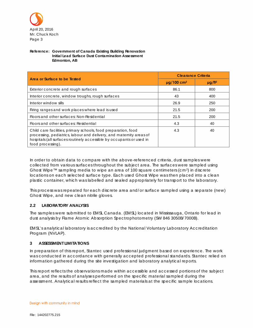
Area or Surface to be Tested Clearance Criteria
μg/100 cm2 μg/ft2
Exterior concrete and rough surfaces 86.1 800
Interior concrete, window troughs, rough surfaces 43 400
Interior window sills 26.9 250
Firing ranges and work places where lead is used 21.5 200
Floors and other surfaces: Non-Residential 21.5 200
Floors and other surfaces: Residential 4.3 40
Child care facilities, primary schools, food preparation, food processing, pediatrics, labour and delivery, and maternity areas of hospitals (all surfaces routinely accessible by occupants or used in food processing).
4.3 40
In order to obtain data to compare with the above-referenced criteria, dust samples were collected from various surfaces throughout the subject area. The surfaces were sampled using Ghost Wipe™ sampling media to wipe an area of 100 square centimeters (cm2) in discrete locations on each selected surface type. Each used Ghost Wipe was then placed into a clean plastic container, which was labelled and sealed appropriately for transport to the laboratory.
This process was repeated for each discrete area and/or surface sampled using a separate (new) Ghost Wipe, and new clean nitrile gloves.
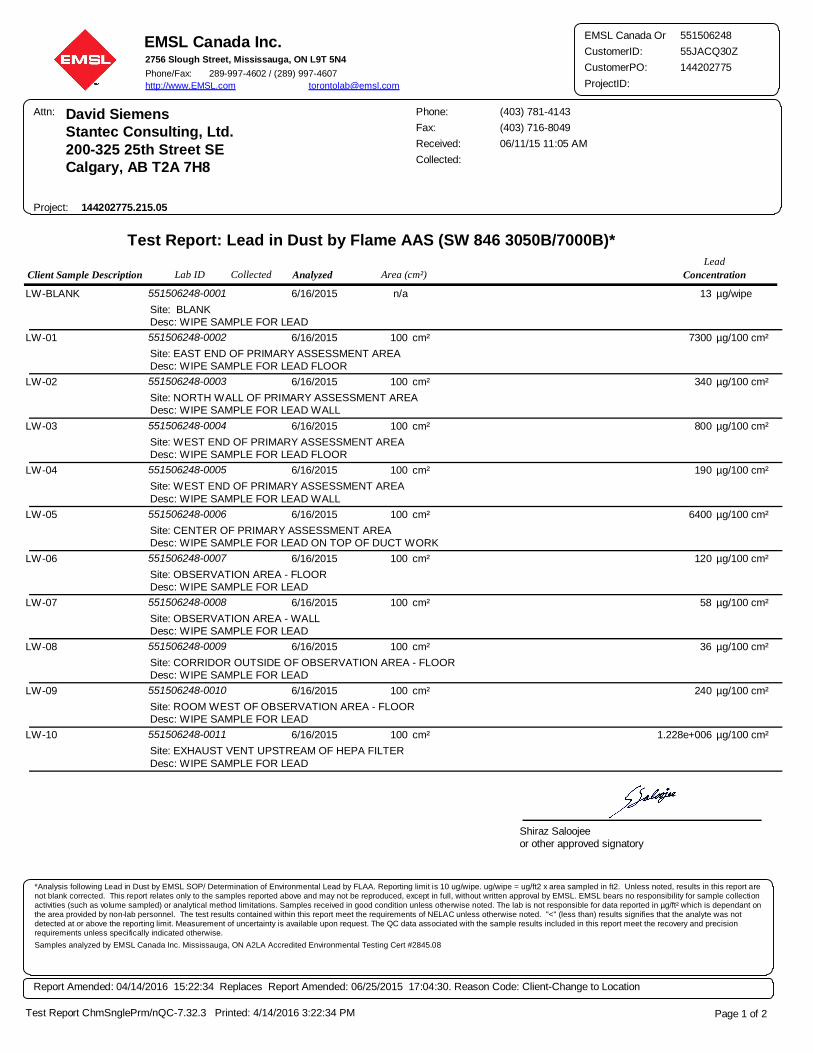
2.2 LABORATORY ANALYSIS
The samples were submitted to EMSL Canada. (EMSL) located in Mississauga, Ontario for lead in dust analysis by Flame Atomic Absorption Spectrophotometry (SW 846 3050B/7000B).
EMSL’s analytical laboratory is accredited by the National Voluntary Laboratory Accreditation Program (NVLAP).
3 ASSESSMENT LIMITATIONS
In preparation of this report, Stantec used professional judgment based on experience. The work was conducted in accordance with generally accepted professional standards. Stantec relied on information gathered during the site investigation and laboratory analytical reports.
This report reflects the observations made within accessible and accessed portions of the subject area, and the results of analyses performed on the specific material sampled during the assessment. Analytical results reflect the sampled materials at the specific sample locations.
File: 144202775.215
April 20, 2016 Mr. Chuck Koch Page 4
Reference: Government of Canada Existing Building Renovation Initial Lead Surface Dust Contamination Assessment Edmonton, AB
Sampling and assessment associated with this report were limited surfaces within the primary assessment area and associated areas (for lead dust), within the subject area.
This report has been prepared for the exclusive use of the Government of Canada for the purpose of assessing general conditions in the subject area as the pertain to lead dust. Any use that a third party makes of this report, or reliance on, or decisions to be made on it, are the responsibility of such third parties. Stantec accepts no responsibility for damages, if any, suffered by any third party as a result of decisions made or actions based on this report.
4 ASSESSMENT RESULTS
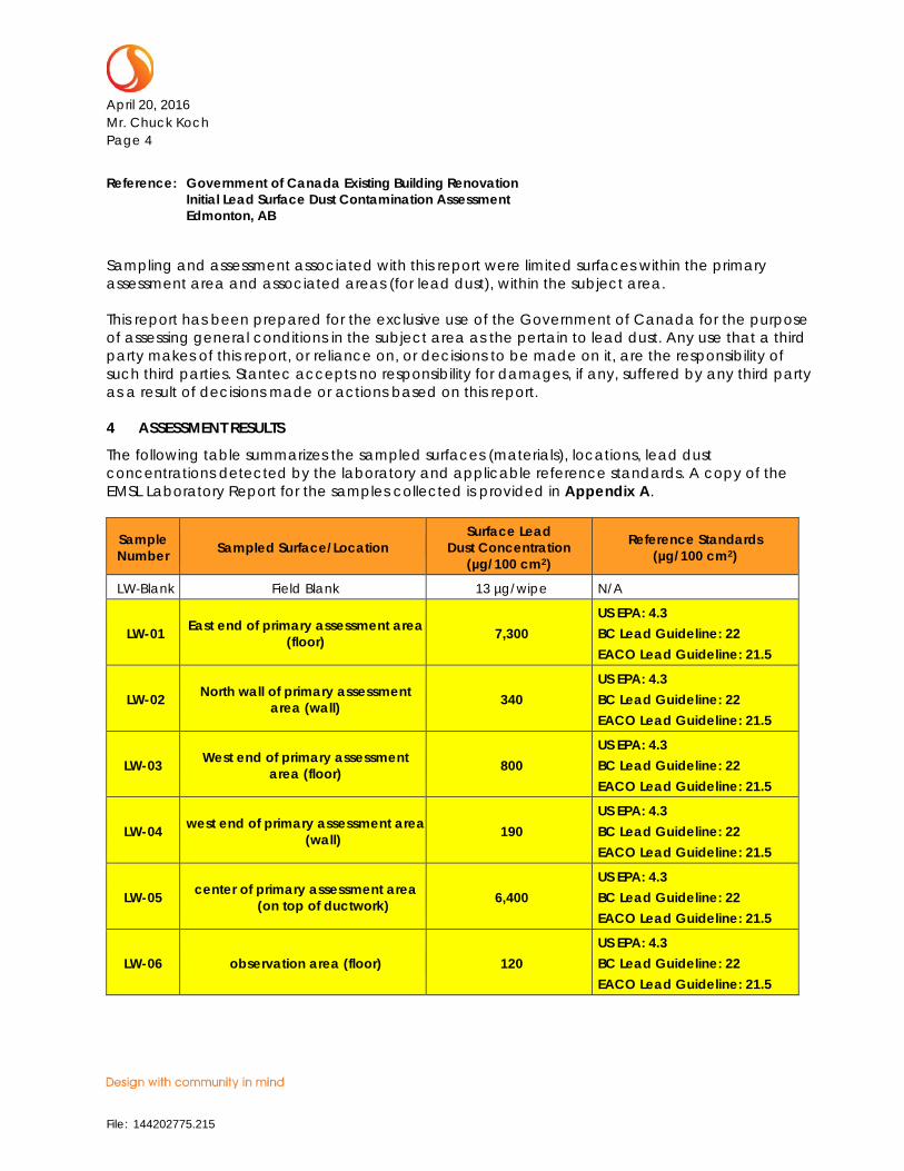
The following table summarizes the sampled surfaces (materials), locations, lead dust concentrations detected by the laboratory and applicable reference standards. A copy of the EMSL Laboratory Report for the samples collected is provided in Appendix A.
Sample Number Sampled Surface/Location
Surface Lead Dust Concentration
(µg/100 cm2)
Reference Standards (µg/100 cm2)
LW-Blank Field Blank 13 µg/wipe N/A
LW-01 East end of primary assessment area (floor) 7,300
US EPA: 4.3 BC Lead Guideline: 22 EACO Lead Guideline: 21.5
LW-02 North wall of primary assessment area (wall) 340
US EPA: 4.3 BC Lead Guideline: 22 EACO Lead Guideline: 21.5
LW-03 West end of primary assessment area (floor) 800
US EPA: 4.3 BC Lead Guideline: 22 EACO Lead Guideline: 21.5
LW-04 west end of primary assessment area (wall) 190
US EPA: 4.3 BC Lead Guideline: 22 EACO Lead Guideline: 21.5
LW-05 center of primary assessment area (on top of ductwork) 6,400
US EPA: 4.3 BC Lead Guideline: 22 EACO Lead Guideline: 21.5
LW-06 observation area (floor) 120 US EPA: 4.3 BC Lead Guideline: 22 EACO Lead Guideline: 21.5
File: 144202775.215
April 20, 2016 Mr. Chuck Koch Page 5
Reference: Government of Canada Existing Building Renovation Initial Lead Surface Dust Contamination Assessment Edmonton, AB
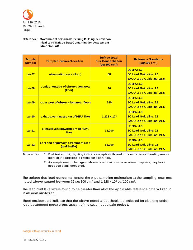
Sample Number Sampled Surface/Location
Surface Lead Dust Concentration
(µg/100 cm2)
Reference Standards (µg/100 cm2)
LW-07 observation area (floor) 58 US EPA: 4.3 BC Lead Guideline: 22 EACO Lead Guideline: 21.5
LW-08 corridor outside of observation area (floor) 36
US EPA: 4.3 BC Lead Guideline: 22 EACO Lead Guideline: 21.5
LW-09 room west of observation area (floor) 240 US EPA: 4.3 BC Lead Guideline: 22 EACO Lead Guideline: 21.5
LW-10 exhaust vent upstream of HEPA filter 1.228 x 10⁶ US EPA: 4.3 BC Lead Guideline: 22 EACO Lead Guideline: 21.5
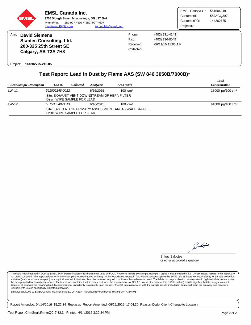
LW-11 exhaust vent downstream of HEPA filter 18,000
US EPA: 4.3 BC Lead Guideline: 22 EACO Lead Guideline: 21.5
LW-12 east end of primary assessment area (wall baffle) 61,000
US EPA: 4.3 BC Lead Guideline: 22 EACO Lead Guideline: 21.5
Table notes: 1. Bold text and highlighting indicates samples with lead concentrations exceeding one or more of the applicable criteria for clearance.
2. As samples are for background/initial contamination assessment purposes, they have not been blank-corrected.
The surface dust lead concentrations for the wipe sampling undertaken at the sampling locations noted above ranged between 36 µg/100 cm2 and 1.228 x 10⁶ µg/100 cm2.
The lead dust levels were found to be greater than all of the applicable reference criteria listed in in all locations tested.
These results would indicate that the above-noted areas should be included for cleaning under lead abatement precautions, as part of the systems upgrade project.
File: 144202775.215
April 20, 2016 Mr. Chuck Koch Page 6
Reference: Government of Canada Existing Building Renovation Initial Lead Surface Dust Contamination Assessment Edmonton, AB
5 RECOMMENDATIONS
As concentrations of lead in dust in excess of accepted “clearance” criteria were identified, lead dust should be abated (removed) from surfaces prior to disturbances that will be required as part of the planned systems upgrade project.
Lead dust abatement should be conducted by appropriately trained professionals (typically, abatement contractor personnel), in accordance with accepted standards and practices for such work.
6 CLOSURE
This report has been prepared for the sole benefit of the Government of Canada. Any use which a third party makes of this report, or any reliance on decisions based on it, is the responsibility of such third parties. Stantec Consulting Ltd. accepts no responsibility for damages, if any, suffered by any third party as a result of decisions made or actions based on this report.
The information and conclusions contained in this report are based upon work undertaken by trained professionals and technical staff in accordance with generally accepted engineering, scientific and occupational health and safety practices current at the time the work was performed. Conclusions presented in this report should not be construed as legal advice.
The conclusions presented in this report represent the best technical judgment of Stantec Consulting Ltd. based on the data obtained from the work.
The conclusions are based on the site conditions encountered by Stantec Consulting Ltd. at the time the work was performed at the specific assessment and/or sampling locations, and can only be extrapolated to an undefined limited area around these locations. The extent of the limited area depends on building construction and conditions, weather, building usage and other factors. Due to the nature of the investigation and the limited data available, Stantec Consulting Ltd. cannot warrant against undiscovered environmental or health and safety liabilities.
If any conditions become apparent that differ significantly from our understanding of conditions as presented in this report, we request that we be notified immediately to reassess the conclusions provided herein.
File: 144202775.215

April 20, 2016 Mr. Chuck Koch Page 7
Reference: Government of Canada Existing Building Renovation Initial Lead Surface Dust Contamination Assessment Edmonton, AB
We trust that the above is satisfactory for your purposes at this time. Should you have any questions or concerns, or require additional information, please do not hesitate to contact the Stantec Project Manager at your convenience.
Regards,
STANTEC CONSULTING LTD.
Lovy Mangat, B.Sc. Report Author Phone: (403) 716-1422 Fax: (403) 716-8049 [email protected]
Sean Brigden, B.Sc., P.B.Dipl., CRSP Associate Tel: (306) 667-2495 Fax: (306) 667-2500 [email protected]
Rob Robinson, P.Eng. Principal Phone: (905) 817-2070 Fax: (905) 858-4426 [email protected]
LM/SB/RR/bv
Attachment: Appendix A – Laboratory Analytical Report –Flame Atomic Absorption Spectrophotometer Analysis
\\cd1002-f04\shared_projects\144202775\hazmat\reports\revised\215 - edmonton\rpt_144202775_215_rcmp_lead_initial_assessment_revised_20160420_fnl.docx
File: 144202775.215

APPENDIX A
Laboratory Analytical Reports – Flame Atomic Absorption Spectrophotometer Analysi
File: 144202775.215
Client Sample Description ConcentrationLab ID Analyzed Area (cm²)Lead
Collected
EMSL Canada Inc.2756 Slough Street, Mississauga, ON L9T 5N4
Phone/Fax: 289-997-4602 / (289) 997-4607
http://www.EMSL.com [email protected]
Attn: David Siemens
Stantec Consulting, Ltd.
200-325 25th Street SE
Calgary, AB T2A 7H8
Received: 06/11/15 11:05 AM
144202775.215.05
Fax: (403) 716-8049
Phone: (403) 781-4143
Project:
Collected:
Test Report: Lead in Dust by Flame AAS (SW 846 3050B/7000B)*
551506248
CustomerID: 55JACQ30Z
CustomerPO: 144202775
ProjectID:
EMSL Canada Or
Site: BLANK
Desc: WIPE SAMPLE FOR LEAD
551506248-0001LW-BLANK n/a 13 µg/wipe6/16/2015
Site: EAST END OF PRIMARY ASSESSMENT AREA
Desc: WIPE SAMPLE FOR LEAD FLOOR
551506248-0002LW-01 100 7300 µg/100 cm²cm²6/16/2015
Site: NORTH WALL OF PRIMARY ASSESSMENT AREA
Desc: WIPE SAMPLE FOR LEAD WALL
551506248-0003LW-02 100 340 µg/100 cm²cm²6/16/2015
Site: WEST END OF PRIMARY ASSESSMENT AREA
Desc: WIPE SAMPLE FOR LEAD FLOOR
551506248-0004LW-03 100 800 µg/100 cm²cm²6/16/2015
Site: WEST END OF PRIMARY ASSESSMENT AREA
Desc: WIPE SAMPLE FOR LEAD WALL
551506248-0005LW-04 100 190 µg/100 cm²cm²6/16/2015
Site: CENTER OF PRIMARY ASSESSMENT AREA
Desc: WIPE SAMPLE FOR LEAD ON TOP OF DUCT WORK
551506248-0006LW-05 100 6400 µg/100 cm²cm²6/16/2015
Site: OBSERVATION AREA - FLOOR
Desc: WIPE SAMPLE FOR LEAD
551506248-0007LW-06 100 120 µg/100 cm²cm²6/16/2015
Site: OBSERVATION AREA - WALL
Desc: WIPE SAMPLE FOR LEAD
551506248-0008LW-07 100 58 µg/100 cm²cm²6/16/2015
Site: CORRIDOR OUTSIDE OF OBSERVATION AREA - FLOOR
Desc: WIPE SAMPLE FOR LEAD
551506248-0009LW-08 100 36 µg/100 cm²cm²6/16/2015
Site: ROOM WEST OF OBSERVATION AREA - FLOOR
Desc: WIPE SAMPLE FOR LEAD
551506248-0010LW-09 100 240 µg/100 cm²cm²6/16/2015
Site: EXHAUST VENT UPSTREAM OF HEPA FILTER
Desc: WIPE SAMPLE FOR LEAD
551506248-0011LW-10 100 1.228e+006 µg/100 cm²cm²6/16/2015
Page 1 of 2
Shiraz Saloojee
or other approved signatory
Test Report ChmSnglePrm/nQC-7.32.3 Printed: 4/14/2016 3:22:34 PM
*Analysis following Lead in Dust by EMSL SOP/ Determination of Environmental Lead by FLAA. Reporting limit is 10 ug/wipe. ug/wipe = ug/ft2 x area sampled in ft2. Unless noted, results in this report are not blank corrected. This report relates only to the samples reported above and may not be reproduced, except in full, without written approval by EMSL. EMSL bears no responsibility for sample collection activities (such as volume sampled) or analytical method limitations. Samples received in good condition unless otherwise noted. The lab is not responsible for data reported in µg/ft² which is dependant on the area provided by non-lab personnel. The test results contained within this report meet the requirements of NELAC unless otherwise noted. "<" (less than) results signifies that the analyte was not detected at or above the reporting limit. Measurement of uncertainty is available upon request. The QC data associated with the sample results included in this report meet the recovery and precision requirements unless specifically indicated otherwise.
Samples analyzed by EMSL Canada Inc. Mississauga, ON A2LA Accredited Environmental Testing Cert #2845.08
Report Amended: 04/14/2016 15:22:34 Replaces Report Amended: 06/25/2015 17:04:30. Reason Code: Client-Change to Location
Client Sample Description ConcentrationLab ID Analyzed Area (cm²)Lead
Collected
EMSL Canada Inc.2756 Slough Street, Mississauga, ON L9T 5N4
Phone/Fax: 289-997-4602 / (289) 997-4607
http://www.EMSL.com [email protected]
Attn: David Siemens
Stantec Consulting, Ltd.
200-325 25th Street SE
Calgary, AB T2A 7H8
Received: 06/11/15 11:05 AM
144202775.215.05
Fax: (403) 716-8049
Phone: (403) 781-4143
Project:
Collected:
Test Report: Lead in Dust by Flame AAS (SW 846 3050B/7000B)*
551506248
CustomerID: 55JACQ30Z
CustomerPO: 144202775
ProjectID:
EMSL Canada Or
Site: EXHAUST VENT DOWNSTREAM OF HEPA FILTER
Desc: WIPE SAMPLE FOR LEAD
551506248-0012LW-11 100 18000 µg/100 cm²cm²6/16/2015
Site: EAST END OF PRIMARY ASSESSMENT AREA - WALL BAFFLE
Desc: WIPE SAMPLE FOR LEAD
551506248-0013LW-12 100 61000 µg/100 cm²cm²6/16/2015
Page 2 of 2
Shiraz Saloojee
or other approved signatory
Test Report ChmSnglePrm/nQC-7.32.3 Printed: 4/14/2016 3:22:34 PM
*Analysis following Lead in Dust by EMSL SOP/ Determination of Environmental Lead by FLAA. Reporting limit is 10 ug/wipe. ug/wipe = ug/ft2 x area sampled in ft2. Unless noted, results in this report are not blank corrected. This report relates only to the samples reported above and may not be reproduced, except in full, without written approval by EMSL. EMSL bears no responsibility for sample collection activities (such as volume sampled) or analytical method limitations. Samples received in good condition unless otherwise noted. The lab is not responsible for data reported in µg/ft² which is dependant on the area provided by non-lab personnel. The test results contained within this report meet the requirements of NELAC unless otherwise noted. "<" (less than) results signifies that the analyte was not detected at or above the reporting limit. Measurement of uncertainty is available upon request. The QC data associated with the sample results included in this report meet the recovery and precision requirements unless specifically indicated otherwise.
Samples analyzed by EMSL Canada Inc. Mississauga, ON A2LA Accredited Environmental Testing Cert #2845.08
Report Amended: 04/14/2016 15:22:34 Replaces Report Amended: 06/25/2015 17:04:30. Reason Code: Client-Change to Location
GOVERNMENT OF CANADA
Existing Building Renovation Section 03 10 00
Alberta, Canada CONCRETE FORMING AND ACCESORIES
Project No.: 144202775.215 Page 1 of 10
Stantec Consulting Ltd.
Part 1 General
1.1 RELATED SECTIONS
.1 Concrete Reinforcing Section 03 20 00
.2 Cast-in-Place Concrete Section 03 30 00
.3 Rough Carpentry Section 06 10 00
1.2 WORK INSTALLED BUT SUPPLIED UNDER OTHER SECTIONS
.1 Install materials specified to be supplied under other sections of these project
specifications. Materials include but are not limited to:
.1 Fabricated components, anchor bolts, bearing plates, sleeves and other inserts to
be built into concrete.
.2 Ensure installation is to the satisfaction of trades concerned and of the Engineer prior to
placing concrete.
1.3 REFERENCE STANDARDS
.1 Perform all work in accordance with the following standards, except where specified
otherwise. All standards to be latest issue at time of tender.
.1 NBC 2010, “National Building Code”.
.2 Canadian Standards Association (CSA International)
.1 CSA-A23.1-10/CSA-A23.2-10, “Concrete Materials and Methods of
Concrete Construction/Methods of Test and Standard Practices for
Concrete”.
.2 CSA-A23.3-10, “Design of Concrete Structures”.
.3 CSA B111-1974 (R2003), “Wire Nails, Spikes and Staples”.
.4 CAN/CSA-O86-09, “Engineering Design in Wood (Limit States
Design)”.
.5 CSA-O121-08(R2013), “Douglas Fir Plywood”.
.6 CAN/CSA-O141-05(R2014), “Softwood Lumber”.
.7 CSA-O151-09(R2014), “Canadian Softwood Plywood”.

GOVERNMENT OF CANADA
Existing Building Renovation Section 03 10 00
Alberta, Canada CONCRETE FORMING AND ACCESORIES
Project No.: 144202775.215 Page 2 of 10
Stantec Consulting Ltd.
.8 CSA-O153-M1980 (R2008), “Poplar Plywood”.
.9 CSA-O325-07(R2012), “Construction Sheathing”.
.10 CSA-O437 Series-93 (R2011), “Standards on OSB and Waferboard”.
.11 CSA-S269.1-2016, “Falsework & Formwork”.
.3 Underwriters’ Laboratories of Canada (ULC)
.1 CAN/ULC-S701-11, “Standard for Thermal Insulation, Polystyrene,
Boards and Pipe Covering”.
.4 Provincial safety standards where applicable.
.5 Conform to applicable safety regulations for erection, maintenance and removal
of formwork.
1.4 REGULATIONS
.1 Abide by the current bylaws and regulations of the province and/or municipality in
which the work is located, and abide by the current laws and regulations with regard to
public safety.
.2 The regulations of the Minister of Labour, Occupational Health and Safety Act, the
Workers’ Compensation Board and other applicable acts administered by the authority
having jurisdiction of the province apply to the work of this section.
1.5 SAFETY
.1 Carry out work in accordance with the current Occupational Health and Safety Act and
construction safety regulations.
1.6 QUALIFICATIONS
.1 Engage a professional structural engineer registered in the Province of Alberta, fully
qualified and experienced in the design of formwork and shoring, to be responsible for
the design of formwork, scaffolding, shoring, re-shoring and all other components
required for formwork erection.
1.7 SUBMITTALS
.1 Indicate method and schedule of construction, shoring, stripping, and re-shoring
procedures, materials, grades, dimensions, arrangement of joints, special architectural
exposed finishes, ties, liners, and locations of temporary embedded parts. Comply with
CSA-S269.1 for falsework & formwork drawings.
GOVERNMENT OF CANADA
Existing Building Renovation Section 03 10 00
Alberta, Canada CONCRETE FORMING AND ACCESORIES
Project No.: 144202775.215 Page 3 of 10
Stantec Consulting Ltd.
.2 Indicate formwork design data: permissible rate of concrete placement, stripping
requirement, and temperature of concrete in forms.
.3 Indicate sequence of erection and removal of formwork/falsework as directed by
Consultant.
.4 Submit all proposed joint details, locations and construction procedures. Include
waterstop, crack inducer, reglet, sealant and joint filler products as required.
.5 Review of the shop drawings by the Engineer is intended to assist the Contractor and
does not relieve the Contractor of responsibility for the completeness and accuracy of the
work and its conformance with the contract drawings and specifications.
.6 Fabrication that commences prior to shop drawing review by the Engineer is at the risk
of the Contractor.
1.8 DELIVERY, STORAGE AND HANDLING
.1 Deliver all materials to the site in bundles easily identified and properly marked.
.2 Store and handle all material on site in a manner to prevent damage and contamination.
1.9 QUALITY CONTROL
.1 The Contractor’s professional engineer responsible for the design of formwork is to
inspect the fabrication and erection of formwork.
.2 The Contractor is not to assign the responsibility of coordination of forming, placing
reinforcing steel, placing other required material and placing concrete. Ensure a full-
time qualified superintendent representing the Contractor is in attendance to inspect and
check all phases of this work.
Part 2 Products
2.1 FORMWORK MATERIALS
.1 Plywood:
.1 Douglas fir conforming to CSA-O121 or softwood conforming to CSA-O151 or
CSA-O153 as required to resist design loads imposed upon the forming system.
Regular grade select tight face. Sound, undamaged sheets with clean, true finish.
.2 Lumber: SPF species, No. 2 Grade or better, conforming to CSA-O141 and to the design
requirements of CAN/CSA-O86.1 to resist applied loads required of the forming
system.
GOVERNMENT OF CANADA
Existing Building Renovation Section 03 10 00
Alberta, Canada CONCRETE FORMING AND ACCESORIES
Project No.: 144202775.215 Page 4 of 10
Stantec Consulting Ltd.
.3 Anchorage devices (including nails, bolts, spikes and lag screws): Sized to ensure all
formwork loadings are adequately resisted. Nails, spikes and staples conforming to
CSA-B111 galvanized or phosphatized.
.4 Steel forms: Minimum 1.6 mm well matched, tight fitting and adequately stiffened to
support weight of concrete without deflection.
.5 Form ties for all concrete below grade or exposed to weather:
.1 Snap off metal ties with 40 mm length cone to resist all forces.
.2 Removable ties to resist all forces that will permit a recessed or flush finish.
.6 Form tie hole sealant: One-component polymeric sealant. Cementitious Non-Shrink
Grout. Natural grey or colour to match concrete.
.7 Form release agent: Ecologo certified under the Environmental Choice Program (ECP)
or, if not Ecologo certified, the Contractor shall:
.1 provide a product that conforms to the requirements for concrete release agents
in accordance eith ECP Certification Criteria Document (CCD) 143 governing
Asphalt and Concrete Release Agents, excluding the provisions under
Conditions for Ecologo Use and,
.2 if requested, provide the Engineer with the same rights as the ECP under CCD
143 with regard to verification of product compliance.
.8 Fillets for chamfered corners: Minimum 12 mm x 12 mm wood.
.9 Void form: Closed celled expanded polystyrene complete with void spaces specifically
designed to allow frost heave and swelling of soil under concrete without inducing
uplift on the concrete. Structurally sufficient to support weight of wet concrete
100mm thick.
.10 Void forms: Moisture-resistant treated paper faces, biodegradable, structurally sufficient
to support weight of wet concrete until initial set, 100mm thick. Use wax mat with
minimum compressive strength of 0.12 MPa.
.11 Grade beam void form: Expanded polystyrene (EPS) configured to support a maximum
load of 25 kPa. Use Geospan by Plastifab or approved alternate.
.12 Grade beam and wall void form protection: Provide polyethylene protection under
biodegradable void form as required to protect the void form from moisture and
premature failure prior to placing concrete
GOVERNMENT OF CANADA
Existing Building Renovation Section 03 10 00
Alberta, Canada CONCRETE FORMING AND ACCESORIES
Project No.: 144202775.215 Page 5 of 10
Stantec Consulting Ltd.
.13 Structural slab on grade void form protection: Provide plywood or hard board as
required over void form to protect the form from crushing under construction
activities and reinforcement chairing.
.14 Void protection: Wood preserved pressure treated plywood, 12 mm thick by 250 mm
high each side of biodegradable void form to ensure void space.
.1 Wood cement composites:
.2 Rigid insulation board: to CAN/ULC-S701
.15 Form stripping agent: colourless mineral oil, non-toxic, biodegradable, low VOC, free of
kerosene, with viscosity between 70 and 110s Saybolt Universal 15 to 24 mm2/s at 40
degrees C, flashpoint minimum 150 degrees C, open cup.
.16 Falsework materials: to CSA-S269.1.
Part 3 Execution
3.1 FABRICATION AND ERECTION
.1 Fabricate and erect falsework in accordance with CSA S269.1
.2 Refer to architectural drawings for concrete members requiring architectural exposed
finishes.
.3 Verify lines, levels and centres before proceeding with formwork. Ensure that
dimensions agree with drawings.
.4 Do not place shores and mud sills on frozen ground.
.5 Provide site drainage to prevent washout of soil supporting mud sills and shores.
.6 Fabricate and erect formwork in accordance with CAN/CSA-S269.1 to produce finished
concrete conforming to shape, dimensions, locations and levels indicated within
tolerances required by CSA-A23.1/A23.2.
.7 Ensure that supplied equipment, hardware, and items to be cast-in will fit concrete
dimensions.
.8 Construct formwork, shoring and bracing accurately to meet design and code
requirements so that resultant finished concrete conforms to shapes, lines, levels and
dimensions indicated on drawings.
.9 Provide bracing to ensure stability of formwork as a whole. Prop or strengthen all
previously constructed elements liable to be overstressed by construction loads.
GOVERNMENT OF CANADA
Existing Building Renovation Section 03 10 00
Alberta, Canada CONCRETE FORMING AND ACCESORIES
Project No.: 144202775.215 Page 6 of 10
Stantec Consulting Ltd.
.10 Arrange and assemble formwork so as to permit easy dismantling and stripping so that
concrete is not damaged during its removal.
.11 Align joints and make watertight to prevent leakage of mortar and disfigured appearance
of concrete. Keep form joints to a minimum. Obtain approval of Engineer for location
of form joints in exposed work.
.12 Chamfer external corners and edges of beams and walls 12 mm when exposed or as
noted.
.13 Provide 12 mm fillets at interior corners and joints unless specified otherwise.
.14 Construct formwork to maintain concrete tolerances in accordance with CSA-A23.1,
Clause 10.
.15 Construct formwork to maintain the following minimum tolerances:
.1 Variation for cross sections and offsets:
.1 Up to 0.3 m ±8 mm.
.2 Up to 1.0 m ±12 mm.
.3 Maximum ±20 mm.
.2 Vertical alignment to be within 1:400 with a maximum 40 mm.
.3 Horizontal alignment to be within 1:400 with a maximum of 40 mm.
.16 Camber beams: 0.2% of span unless otherwise noted.
.17 Apply form release agent on formwork in accordance with manufacturer’s
recommendations. Apply prior to placing reinforcing steel, anchoring devices and
embedded parts.
.18 Do not apply form release agent where concrete surfaces are to receive special finishes
or applied coverings which are affected by agent. Soak inside surfaces of untreated
forms with clean water and keep moist prior to placing concrete.
.19 Do not re-use formwork with surface defects that will impair the appearance of finished
concrete. Do not patch formwork. Meet the requirements of Part 2 of this section when
re-using formwork.
.20 Verify top of pile elevations. Cut down piles or increase lengths as required to the
proper elevations. Ensure piles project into grade beams and pile caps as indicated on
drawings.
GOVERNMENT OF CANADA
Existing Building Renovation Section 03 10 00
Alberta, Canada CONCRETE FORMING AND ACCESORIES
Project No.: 144202775.215 Page 7 of 10
Stantec Consulting Ltd.
.21 Remove all loose concrete from tops of piles. Ensure tops of piles are clean and of
sound concrete.
.22 Provide sufficient space below grade beams and walls for void form and void protection.
Place void form prior to reinforcement to ensure specified concrete cover.
.23 Prepare structural slab on grade subgrade to prevent moisture degradation of void form.
Do not use polyethylene protection.
.24 Form construction joints in accordance with CSA-A23.1 at locations indicated on the
drawings or with the written approval of the Engineer as follows:
.1 At centre of span of suspended slabs.
.2 In grade beams at midspan.
.3 In walls immediately above and below floor construction joints.
.25 Construction joints in walls and grade beams maximum 12 m or as detailed.
.26 Construction joints in slabs on grade maximum 24 m or as detailed.
.27 Proposed construction joint locations and details to be approved by the Engineer.
3.2 CLEANING FORMS
.1 Clean formwork in accordance with CSA-A23.1/A23.2, before placing concrete.
.2 Clean forms as erection proceeds to remove foreign matter. Remove cuttings, shavings
and debris from within forms. Flush completely with water or compressed air to remove
remaining foreign matter. Ensure that water and debris drain to exterior through clean-
out ports. Do not use water to clean forms where hydrophyllic type water stops are
specified.
.3 During cold weather, remove ice and snow from within forms. Do not use de-icing salts.
Do not use water to clean out completed forms unless formwork and concrete
construction proceed within a heated enclosure. Use compressed air or other means to
remove foreign matter.
.4 Provide temporary ports or openings in formwork where required to facilitate cleaning
and inspection. Locate openings at bottom of forms to allow flushing water to drain.
Close temporary ports or openings with tight-fitting panels, flush with inside of forms,
neatly fitted so that joints will not be apparent in exposed concrete surfaces.

GOVERNMENT OF CANADA
Existing Building Renovation Section 03 10 00
Alberta, Canada CONCRETE FORMING AND ACCESORIES
Project No.: 144202775.215 Page 8 of 10
Stantec Consulting Ltd.
3.3 INSERTS/EMBEDDED PARTS/OPENINGS
.1 Provide formed openings/chases or slots where required for pipes, conduits, sleeves and
other work to be embedded in and passing through concrete members.
.2 Refer to architectural, mechanical and electrical drawings for sleeves and openings
required through structural components. These are not to reduce the structural capacity.
Locations and sizes not shown on the structural drawings are to be approved in writing
by the Engineer.
.3 Maximum size of electrical conduit in structural slabs is 1/5 of solid portion of the slab
thickness, and where more than two are adjacent to each other, they are to be spaced
100 mm apart. Conduit is to be placed in the middle third of the slab.
.4 Provide recesses in top of foundation walls at all doors and openings to allow slab to
bear on walls.
.5 Accurately locate and set in place all items that are to be cast directly in concrete.
.6 Coordinate work of other sections and cooperate with the trade involved in forming
and/or setting openings, slots, recesses, chases, sleeves, bolts, anchors and other inserts.
Do not perform work unless specifically indicated on drawings or approved prior to
installation.
.7 Do not place anchor bolts, sleeves and inserts into freshly placed concrete. Tie firmly
into place prior to placing concrete.
.8 Ensure that anchors and inserts will not protrude beyond surfaces designated to receive
applied finishes, including paint.
.9 Install all concrete accessories in accordance with drawings and manufacturer’s
recommendations, straight, level and plumb. Ensure adequate support to prevent
movement during concrete placement.
3.4 FORM REMOVAL AND RESHORING
.1 Comply with CSA-S269.1 for dismantling all falsework.
.2 Leave formwork in placed for following minimum periods of time after placing concrete.
.1 3 days for walls.
.3 Space reshoring in each principal direction at not more than 3000mm apart.
.4 Re-use formwork and falsework subject to requirements of CSA-A23.1/A23.2.
GOVERNMENT OF CANADA
Existing Building Renovation Section 03 10 00
Alberta, Canada CONCRETE FORMING AND ACCESORIES
Project No.: 144202775.215 Page 9 of 10
Stantec Consulting Ltd.
.5 Do not remove forms, shores and bracing until concrete has gained sufficient strength to
carry its own weight, construction loads and the design loads that are liable to be
imposed upon it. Verify strength of concrete by compression tests to the satisfaction of
the Engineer.
.6 Remove forms not directly supporting weight of concrete as soon as stripping operations
will not damage concrete but not before a minimum of three days from final concrete
placement to prevent rapid loss of moisture from concrete.
.7 Arrange forms to allow removal without removal of principal shores where these are
required to remain in place.
.8 Retain shores and forms under structural members for a minimum of 14 days or until the
concrete has attained 75% of the required 28 day strength, whichever occurs later.
.9 Beams, slabs and joists are to remain shored, or re-shoring sequence is to be controlled,
to prevent excessive dead load deflections.
.10 Verify strength by field cylinders or insert type tests in accordance with ASTM C900-T.
.11 Remove formwork progressively and in accordance with code requirements so that no
shock loads or unbalanced loads are imposed on structure.
.12 Loosen forms carefully. Do not damage concrete by wedging pry bars, hammers or tools
against concrete surfaces.
.13 Re-shore structural members as required for design or construction conditions.
Construction is to be re-shored to carry all future anticipated construction loading unless
otherwise approved in writing by the Engineer.
3.5 VOID FORM
.1 Ensure void form is in place and not damaged prior to placing concrete (top protection
may be required – by contractor).
.2 Install void space protection prior to backfilling walls and grade beams (required for
biodegradable void form only).
.3 Install void form top protection for structural slabs on grade.
3.6 CERTIFICATION
.1 At the completion of formwork and shoring, the Contractor’s professional engineer shall
certify all formwork components fabricated and erected by the Contractor is in
accordance with his design drawings.

GOVERNMENT OF CANADA
Existing Building Renovation Section 03 10 00
Alberta, Canada CONCRETE FORMING AND ACCESORIES
Project No.: 144202775.215 Page 10 of 10
Stantec Consulting Ltd.
.2 Certify that all formwork, shoring and components are capable of supporting all the
construction loads and forces required to complete the cast-in-place concrete work.
END OF SECTION
GOVERNMENT OF CANADA
Existing Building Renovation Section 03 20 00
Alberta, Canada CONCRETE REINFORCING
Project No.: 144202775.215 Page 1 of 7
Stantec Consulting Ltd.
Part 1 General
1.1 RELATED WORK SPECIFIED IN OTHER SECTIONS
.1 Concrete Forming and Accessories Section 03 10 00
.2 Cast-in-Place Concrete Section 03 30 00
.3 Concrete Finishing Section 03 35 00
1.2 REFERENCE STANDARDS
.1 Perform all work in accordance with the following standards, except where specified otherwise.
All standards to be latest issue at time of tender.
.1 NBC 2010, “National Building Code”.
.2 American Concrete Institute (ACI)
.1 SP-66-04, ACI Detailing Manual 2004
.1 ACI 315-99, “Details and Detailing of Concrete Reinforcement”.
.2 ACI 315R-04, “Manual of Structural and Placing Drawings for
Reinforced Concrete Structures”.
.3 American Society for Testing and Materials International (ASTM)
.1 ASTM A143/A143M-07, “Standard Practice for Safeguarding Against
Embrittlement of Hot-Dip Galvanized Structural Steel Products and Procedure
for Detecting Embrittlement”.
.2 ASTM A1064 / A1064M - 14, “Standard Specification for Carbon-Steel Wire
and Welded Wire Reinforcement, Plain and Deformed, for Concrete”.
.3 ASTM A123/A123M-15 Standard Specification for Zinc (Hot-Dip Galvanized)
Coatings on Iron and Steel Products.
.4 Canadian Standards Association (CSA International)
.1 CSA-A23.1-10/CSA-A23.2-10, “Concrete Materials and Methods of Concrete
Construction/Methods of Test and Standard Practices for Concrete”.
.2 CSA-A23.3-10, “Design of Concrete Structures”
.3 CAN/CSA-G30.18-09 (R2014), “Billet-Steel Bars for Concrete Reinforcement,
A National Standard of Canada”.

GOVERNMENT OF CANADA
Existing Building Renovation Section 03 20 00
Alberta, Canada CONCRETE REINFORCING
Project No.: 144202775.215 Page 2 of 7
Stantec Consulting Ltd.
.4 CAN/CSA-G40.20-13/CAN/CSA-G40.21-13, “General Requirements for Rolled
or Welded Structural Quality Steel/Structural Quality Steel”.
.5 CSA-W186-M1990 (R2012), “Welding of Reinforcing Bards in Reinforced
Concrete Construction”.
.5 Reinforcing Steel Institute of Canada (RSIC)
.1 RSIC 2004, “Reinforcing Steel Manual of Standard Practice”.
.6 Concrete Reinforcing Steel Institute (CRSI) where noted.
1.3 REGULATIONS
.1 Abide by the current bylaws and regulations of the province and/or municipality in which the work
is located, and abide by the current laws and regulations with regard to crossing and public safety.
.2 The regulations of the Minister of Labour, Occupational Health and Safety Act, the Workers’
Compensation Board and other applicable acts administered by the authority having jurisdiction of
the province apply to the work of this section.
1.4 SAFETY
.1 Carry out cast-in-place concrete work in accordance with the current Occupational Health and
Safety Act and construction safety regulations.
1.5 SUBMITTALS
.1 Prepare and submit reinforcement drawings in accordance with RSIC Manual of Standard Practice.
.2 Quality Assurance:
.1 Mill Test Report: upon request provide Engineer with certified copy of mill test report of
reinforcing steel, minimum 4 weeks prior to beginning reinforcing work.
.2 Upon request submit in writing to Engineer proposed source of reinforcement material to
be supplied.
.3 Submit results of ladle analysis of all reinforcement to be spliced by welding, and submit
manufacturer’s information and test reports for mechanical splices of all reinforcement to be
mechanically spliced.
.4 Submit responses to all site review reports stating that all reported defects and deficiency items
were corrected or stating what action was taken.
1.6 SHOP DRAWINGS
.1 Submit shop drawings including placing of reinforcement and indicate:
.1 Bar bending details.
GOVERNMENT OF CANADA
Existing Building Renovation Section 03 20 00
Alberta, Canada CONCRETE REINFORCING
Project No.: 144202775.215 Page 3 of 7
Stantec Consulting Ltd.
.2 Lists.
.3 Quantities of reinforcement.
.4 Sizes, spacings, locations of reinforcement and mechanical splices if approved by
Engineer.
.5 Indicate sizes, spacings and locations of chairs, spacers and hangers.
.2 Detail lap lengths and bar development lengths to CSA-A23.3, unless otherwise indicated.
.1 Provide Type B tension lap splices, where indicated unless otherwise indicated.
.3 Use large scale details for areas of congested reinforcement.
.4 Review of the shop drawings by the Engineer is intended to assist the Contractor and does not
relieve the Contractor of responsibility for the completeness and accuracy of the work and its
conformance with the contract drawings and specifications.
.5 Fabrication that commences prior to shop drawing review by the Engineer is at the risk of the
Contractor.
1.7 DELIVERY, STORAGE AND HANDLING
.1 Store and manage hazardous materials in accordance with Section 01 47 15 – Sustainable
Requirements: Construction.
.2 Deliver all materials to the site in bundles easily identified and properly marked.
.3 Store and handle all material on site in a manner to prevent damage and contamination.
.4 Do not straighten or re-bend any reinforcement.
.5 Do not use any reinforcement that has been kinked or bent on site.
1.8 PAYMENT
.1 Payment for the work of this section shall be on a lump sum basis as tendered which shall be full
compensation for all labour, materials, and equipment necessary to complete the work, including
all subsidiary and incidental items thereto for which separate payment is not elsewhere provided.
Part 2 Products
2.1 MATERIALS
.1 Substitute different size bars only if permitted in writing by Engineer.
.2 Reinforcing steel for straight reinforcing bars only: To CAN/CSA-G30.18, 400MPa yield grade
deformed billet steel bars.
GOVERNMENT OF CANADA
Existing Building Renovation Section 03 20 00
Alberta, Canada CONCRETE REINFORCING
Project No.: 144202775.215 Page 4 of 7
Stantec Consulting Ltd.
.3 Reinforcing steel for welded and bent reinforcing bars: To CAN/CSA-G30.18, 400W MPa yield
grade special low alloy deformed billet steel. The equivalent carbon content is not to exceed 0.5.
.4 Welded steel wire fabric: To CSA-G30.5, hot dip galvanized to CAN/CSA-G164 flat sheets.
.5 Welded deformed steel wire fabric: To CSA-G30.15, hot dip galvanized, to CAN/CSA-G164 flat
sheets.
.6 Chairs, bolsters, bar supports, spacers to meet requirements of CSA-A23.1/A23.2: Adequate for
strength and support of reinforcing. Where concrete is exposed to view, exposed to elements or
where rust is possible; use plastic or non-corrosive material, or precast concrete made from
concrete of equal strength and durability of concrete to be placed. Chairs used are not to result in
voids or unacceptable appearance in exposed concrete surfaces.
.7 Slab on grade chairs and bar supports: Precast concrete, plastic chairs, or subject to approval
concrete masonry block or brick of correct height. Metal pipe, stone or wood are not acceptable.
Chairs shall be compatible with void form where applicable.
.8 Tie wire: Minimum 1.6 mm type or patented system approved by the Engineer.
.9 Galvanizing of non-prestressed reinforcement: to CAN/CSA-G164, minimum zinc coating 600
g/m2.
.1 Protect galvanized reinforcing steel with chromate treatment to prevent reaction with
Portland cement paste.
.2 If chromate treatment is carried out immediately after galvanizing, soak steel in aqueous
solution containing minimum 0.2% by weight sodium dichromate or 0.2% chromic acid.
.1 Temperature of solution equal to or greater than 32 degrees and galvanized
steels immersed for minimum 20 seconds.
.3 If galvanized steels are at ambient temperature, add sulphuric acid as bonding agent at
concentration of 0.5% to 1%.
.1 In this case, no restriction applies to temperature of solution.
.4 Chromate solution sold for this purpose may replace solution described above, provided it
is of equivalent effectiveness.
.1 Provide product description as described in Part 1 – SUBMITTALS.
.10 Plain round bars: to CAN/CSA-G40.20/CAN/CSA-G40.21.
2.2 FABRICATION
.1 Fabricate reinforcement hooks, bends, laps and similar details to CSA-A23.1, ACI Detailing
Manual 315 and Metric Supplement of the Reinforcing Steel Institute of Canada (RISC) Manual of
Standard Practice and in accordance with the drawings and specifications and the reviewed shop
drawings.

GOVERNMENT OF CANADA
Existing Building Renovation Section 03 20 00
Alberta, Canada CONCRETE REINFORCING
Project No.: 144202775.215 Page 5 of 7
Stantec Consulting Ltd.
.2 Verify dimensions of existing work prior to commencing fabrication.
.3 Verify all drawing dimensions and conditions prior to commencing fabrication.
.4 Bend all reinforcement cold unless otherwise approved by the Engineer.
.5 Provide wall dowels from foundations using same reinforcing as in walls unless noted otherwise on
the drawings.
.6 Provide horizontal, L-shaped corner bars with legs minimum 600 mm of same cross section and
spacing as horizontal bars to a maximum size of 20M or welded wire fabric around wall and grade
beam corners unless otherwise detailed on the drawings.
.7 Provide all additional support bars as required to support all main reinforcement indicated.
.8 Provide stirrup support bars sized to match stirrup size in hooks or corners of beam stirrups unless
noted otherwise on drawings.
.9 Provide 10M “U” spacers at 3 m on centre horizontally and 1.5 m on centre vertically to hold wall
reinforcing mats in position.
.10 Locate reinforcing splices not indicated on drawings at points of minimum stress. Location of
splices is to be approved by the Engineer.
.11 Refer to structural drawings for minimum splices. Splices to be Type B unless noted otherwise.
.12 Provide minimum reinforcing to slabs on grade unless otherwise noted: 100 mm slabs
305 x 305 x MW66.7 x MW66.7 “step through” mesh. An alternative using tied reinforcing steel
providing the equivalent reinforcing value will be considered if approved in writing by the
Engineer.
.13 Lap adjacent sheets of welded steel wire fabric to provide an overlap of at least one cross wire
spacing plus 50 mm.
.14 Obtain Engineer’s approval for locations of reinforcement splices other than those shown on
placing drawings.
.15 Ship bundles of bar reinforcement, clearly identified in accordance with bar bending details and
lists.
Part 3 Execution
3.1 PREPARATION
.1 Galvanizing to include chromate treatment.
.1 Duration of treatment to be 1 hour per 25 mm of bar diameter.
GOVERNMENT OF CANADA
Existing Building Renovation Section 03 20 00
Alberta, Canada CONCRETE REINFORCING
Project No.: 144202775.215 Page 6 of 7
Stantec Consulting Ltd.
.2 Conduct bending tests to verify galvanized bar ductility is in accordance with ASTM
A143/A143M.
3.2 FIELD BENDING
.1 Do not field bend weld reinforcement except where indicated or authorized by Engineer.
.2 When field bending is authorized, bend without heat, applying slow and steady pressure.
.3 Replace bars, which develop cracks or splits.
3.3 PLACING REINFORCEMENT
.1 Place reinforcing steel in accordance with CSA-A23.1/A23.2.
.2 Place reinforcement within a tolerance of ±6 mm for slab steel and ±12 mm for other steel. Bends
and end of bars to be within 50 mm of specified location. Adequately support and secure
reinforcement to prevent movement within the allowable tolerances before and during placing of
concrete.
.3 Place and secure all reinforcement in its correct position prior to placing any concrete. Do not
adjust or place reinforcement in freshly placed concrete.
.4 Reinforce around openings as noted on structural drawings.
.5 Supply and place all necessary support accessories, whether specifically detailed or not, to ensure
proper placement of reinforcing steel.
.6 Use non-corrosive or non-stain supports for reinforcing when concrete is exposed.
.7 Support slab on grade, structural slab and pile cap reinforcement at 900 mm maximum on centre.
.8 Supply bar support chairs for top reinforcing bars in sufficient quantity to not exceed 900 mm
average spacing in each direction.
.9 Supply chairs to support temperature reinforcing or mesh to maintain minimum covers specified.
.10 Ensure supports are such that they are not forced into the supporting formwork, void form or soil
and do not break or collapse from the weight of reinforcement and other construction loads.
.11 Supply horizontal reinforcing spacers in walls to ensure reinforcing does not move during
placement.
.12 Support reinforcement laterally in pairs on opposite faces of walls, columns and beams.
.13 Provide minimum concrete cover to reinforcing steel in accordance with CSA-A23.1, except where
indicated on the drawings.
GOVERNMENT OF CANADA
Existing Building Renovation Section 03 20 00
Alberta, Canada CONCRETE REINFORCING
Project No.: 144202775.215 Page 7 of 7
Stantec Consulting Ltd.
.14 Where a structural concrete member is required to have a fire-resistance rating as identified on the
drawings or in the specifications, provide minimum concrete cover to reinforcing steel in
accordance with the Supplement to the National Building Code, “Fire Performance Ratings”.
.15 Ensure reinforcing is clean, free of loose scale, dirt, oil, rust and other foreign coatings.
.16 Place reinforcement for interior and exterior slabs on grade as indicated on drawings. Place and
support uniformly above centre line of the slab, and have a minimum concrete top cover of 40 mm
interior, 50 mm exterior.
.17 Place reinforcing for slab on grade on precast concrete chairs or other approved supports at correct
height.
.18 Obtain written approval from the Engineer prior to cutting of reinforcing to accommodate
openings, or embedded items or to accommodate timber connections. Allow for additional splice
material which may be required to reinforce these cut bars as directed by the Engineer.
.19 Prior to placing concrete, obtain Engineer’s approval of reinforcing material and placement.
3.4 FIELD TOUCH-UP
.1 Touch up damaged and cut ends of galvanized reinforcing steel with compatible finish to provide
continuous coating.
END OF SECTION
GOVERNMENT OF CANADA
Existing Building Renovation Section 03 30 00
Alberta, Canada CAST-IN-PLACE CONCRETE
Project No.: 144202775.215 Page 1 of 15
Stantec Consulting Ltd.
Part 1 General
1.1 RELATED WORK SPECIFIED IN OTHER SECTIONS
.1 Concrete Forming and Accessories Section 03 10 00
.2 Concrete Reinforcing Section 03 20 00
.3 Concrete Finishing Section 03 35 00
1.2 REFERENCE STANDARDS
.1 Perform cast-in-place concrete work in accordance with the following standards, except where
specified otherwise. All standards to be latest issue at time of tender. Provide one copy on site of
the first four standards listed below.
.1 NBC 2010, “National Building Code”.
.2 American Society for Testing and Materials International (ASTM)
.1 ASTM C260-10a, “Standard Specification for Air-Entraining Admixtures for Concrete”.
.2 ASTM C309-11, “Standard Specification for Liquid Membrane-Forming Compounds for
Curing Concrete”.
.3 ASTM C330-14, “Standard Specification for Lightweight Aggregates for Structural
Concrete”.
.4 ASTM C494/C494M-13, “Standard Specification for Chemical Aggregates for
Concrete”.
.5 ASTM C1017/C1017M-13, “Standard Specification for Chemical Admixtures for Use in
Producing Flowing Concrete”.
.6 ASTM D412-06a(2013), “Standard Test Methods for Vulcanized Rubber and
Thermoplastic Elastomers- Tension”.
.7 ASTM D624-00 (2012), “Standard Test Method for Tear Strength of Conventional
Vulcanized Rubber and Thermoplastic Elastomer”.
.8 ASTM D1751-04(2013), “Standard Specification for Preformed Expansion Joint Filler
for Concrete Paving and Structural Construction (Nonextruding and Resilient Bituminous
Types)”.
.9 ASTM D1752-04a(2013), “Standard Specification for Preformed Sponge Rubber Cork
and Recycled PVC Expansion Joint Fillers for Concrete Paving and Structural
Construction”.
.3 Canadian General Standards Board (CGSB)
GOVERNMENT OF CANADA
Existing Building Renovation Section 03 30 00
Alberta, Canada CAST-IN-PLACE CONCRETE
Project No.: 144202775.215 Page 2 of 15
Stantec Consulting Ltd.
.1 CAN/CGSB-37.2-M88, “Emulsified Asphalt, Mineral Colloid-Type, Unfilled, for
Dampproofing and Waterproofing and for Roof Coatings”.
.2 CAN/CGSB-51.34-M86 (R1988), “Vapour Barrier, Polyethylene Sheet for Use in
Building Construction”.
.4 Canadian Standards Association (CSA International)
.1 CSA-A23.1-09/CSA-A23.2-09, “Concrete Materials and Methods of Concrete
Construction/Methods of Test and Standard Practices for Concrete”.
.2 CSA-A23.3-09, “Design of Concrete Structures”.
.3 CAN3-A438-00(R2004), “Concrete Construction for Housing and Small Buildings”.
.4 CSA-A23.4-09, “Precast Concrete – Materials and Construction”.
.5 CSA-A371-04(R2014), “Masonry Construction for Buildings”.
.6 CSA-A283-06(R2011), “Qualification Code for Concrete Testing Laboratories”.
.7 CAN/CSA-A3000-13, “Cementitious Materials Compendium (Consists of A3001,
A3002, A3003, A3004 and A3005)”.
.8 CAN/CSA-A3001-13, “Cementitious Materials or Use in Concrete”.
1.3 ACRONYMS AND TYPES
.1 Cement: hydraulic cement or blended hydraulic cement (XXb – where b denotes blended).
.1 Type GU or GUb – General use cement.
.2 Type MS or MSb – Moderate sulphate-resistant cement.
.3 Type MH or MHb – Moderate heat of hydration cement.
.4 Type HE or HEb – High early-strength cement.
.5 Type LH or LHb – Low heat of hydration cement.
.6 Type HS or HSb – High sulphate-resistant cement.
.2 Fly Ash:
.1 Type F – with CaO content less than 8%.
.2 Type CI – with CaO content ranging from 8 to 20%.
.3 Type CH – with CaO greater than 20%.
.3 GGBFS – Ground, granulated blast-furnace slag.
GOVERNMENT OF CANADA
Existing Building Renovation Section 03 30 00
Alberta, Canada CAST-IN-PLACE CONCRETE
Project No.: 144202775.215 Page 3 of 15
Stantec Consulting Ltd.
1.4 REGULATIONS
.1 Abide by the current bylaws and regulations of the province and/or municipality in which the work
is located, and abide by the current laws and regulations with regard to public safety.
.2 The regulations of the Minister of Labour, Occupational Health and Safety Act, the Workers’
Compensation Board and other applicable acts administered by the authority having jurisdiction of
the province apply to the work of this section.
1.5 SAFETY
.1 Carry out cast-in-place concrete work in accordance with the current Occupational Health and
Safety Act construction safety regulations.
1.6 CONCRETE MIX DESIGN REQUIREMENTS
.1 Performance: in accordance with CSA-A23.1/A23.2, and as described in Mixes of Part 2 –
PRODUCTS.
1.7 SUBMITTALS
.1 Submit the proposed mix design for all concrete and grout mix types to the Engineer for approval
two weeks prior to their initial use.
.2 Submit data sheets for all proposed pre-mixed grouts to the Engineer for review.
.3 Submit samples of fine and coarse aggregate and all admixtures proposed for concrete mixes to the
testing firm’s laboratory, if requested by the Engineer.
.4 Prior to conducting trial mixes, submit data on all specified or proposed concrete admixtures with
the mix design to the Engineer for approval. Data is to confirm the compatibility of the water
reducing admixture, the superplasticizer, the air entraining agent, the cement, the fly ash and the
silica fume where used.
.5 Submit copies of mill certificate test reports of cement, silica fume and fly ash, if requested by the
Engineer.
.6 Submit data on all concrete accessories specified or proposed.
.7 Submit responses to all site review reports stating that all reported defects and deficiency items
were corrected or stating what action was taken.
.8 Submit testing, inspection, results and reports for review by Engineer and do not proceed without
written approval when deviations from mix design or parameters are found.
.9 Submit proposed quality control procedures.
.10 Concrete pours: submit accurate records of poured concrete items indicating date and location of
pour, quality, air temperature and test samples taken.
GOVERNMENT OF CANADA
Existing Building Renovation Section 03 30 00
Alberta, Canada CAST-IN-PLACE CONCRETE
Project No.: 144202775.215 Page 4 of 15
Stantec Consulting Ltd.
.11 Concrete hauling time: submit for review by Engineer deviations exceeding maximum allowable
time of 2 hours for concrete to be delivered to site of Work and discharged after batching.
1.8 QUALITY ASSURANCE
.1 Quality Assurance: in accordance with Section 01 45 00 – Quality Control.
.2 Submit to Engineer, minimum 4 weeks prior to starting concrete work, valid and recognized
certificate from plant delivering concrete.
.1 When plant does not hold valid certification, provide test data and certification by
qualified independent inspection and testing laboratory that materials based in concrete
mixture will meet specified requirements.
.3 Minimum 4 weeks prior to starting concrete work, submit proposed quality control procedures for
review by Engineer on following items:
.1 Falsework erection.
.2 Hot weather concrete (air temperature above 25C).
.3 Cold weather concrete (air temperature below 5C).
.4 Curing.
.5 Finishes.
.6 Formwork removal.
.7 Floor topping.
1.9 INSPECTION AND TESTING OF CONCRETE
.1 Test all concrete by a testing firm certified in accordance with CSA-A283, retained and paid for by
the Contractor and approved by the Engineer.
.2 Provide casual labour to the testing firm’s field personnel for the purpose of obtaining, handling,
and storing sample materials. Provide free access to all portions of the work, and cooperate with
the testing firm.
.3 Advise testing firm 48 hours in advance of concrete placement.
.4 The Contractor is to provide properly designed temperature-controlled storage boxes for test
cylinders, as specified in CSA-A23.2, for a period of at least 48 hours and further protection from
adverse weather and mishandling until removed from the site. The Contractor is to provide a
max-min thermometer for each storage box. Storage in a portable building that will be used by the
Contractor’s personnel or the Engineer during the first 24 hour storage period will not be
permitted. Storage facilities are to be provided, installed, checked and approved before any
concrete may be placed.
.5 Secure sufficient 3 and 7-day test cylinders for testing of concrete to ensure quality control and
sufficient strength for application of construction loads and formwork stripping. Cost for these
additional tests to be borne by the Contractor.
GOVERNMENT OF CANADA
Existing Building Renovation Section 03 30 00
Alberta, Canada CAST-IN-PLACE CONCRETE
Project No.: 144202775.215 Page 5 of 15
Stantec Consulting Ltd.
.6 Testing firm to conduct all tests in accordance with CSA-A23.2.
.7 Samples of concrete to be taken as close to the point of final deposit in the form as possible, at end
of pipe when pumping is used.
.8 Testing firm to take a minimum of three (3) test cylinders for a strength test and not less than one
strength test for each 50 m3 of concrete, or portion thereof, for each type of concrete placed and
not less than one (1) test for each type of concrete placed in any one day.
.9 Testing firm to moist cure and test one (1) cylinder in 7 days and to moist cure and test the
remaining two (2) cylinders in 28 days or (1) in 7 days, (1) in 28 days and (2) in 56 days.
.10 Testing firm is to take one additional test cylinder during cold weather concreting and cure on job
site under same conditions as the concrete it represents.
.11 Testing firm is to take at least one slump test and one entrained air test for each set of test cylinders
taken.
.12 Testing firm is to report results of tests immediately to the Contractor. The Contractor is
responsible for ensuring that the concrete meets the requirements of the specifications. Report
adverse test results to the Engineer immediately.
.13 Testing firm is not authorized to revoke, relax, enlarge or release any requirements of the
specification, nor to approve or disapprove any portion of the work.
.14 Testing firm is to advise placing crews to halt placing of adverse concrete immediately, and
thereafter notify Contractor to reject the concrete. The execution, or lack of execution, of this
request is to be recorded.
.15 Testing firm is to submit to the Engineer and Contractor certified copies of test results. Include the
following information with the results:
.1 Name of the project.
.2 Date of sampling.
.3 Mix design, specified strength, slump and air content.
.4 Name of supplier, truck and ticket number.
.5 Time batched and time placed.
.6 Identification of sampling and testing technician.
.7 Cement type and admixtures used.
.8 Exact location in the structure of the concrete sampled, including floor, elevation, and
grids where applicable.
.9 Ambient air and concrete temperatures.
.10 Nominal aggregate size.
.11 Water added and personnel authorizing additional water.
GOVERNMENT OF CANADA
Existing Building Renovation Section 03 30 00
Alberta, Canada CAST-IN-PLACE CONCRETE
Project No.: 144202775.215 Page 6 of 15
Stantec Consulting Ltd.
.12 Concrete density.
.16 Testing firm to certify, in writing, that all concrete meets the specified requirements.
.17 Reject and do not place concrete with slumps greater than maximum specified, air content lower
than minimum specified and concrete over 2 hours from batch time.
1.10 INSPECTION AND TESTING OF UNIT MASONRY CORE FILL
.1 All clauses pertaining to inspection and testing of concrete contained in this specification are to
apply to unit masonry grout unless noted otherwise.
.2 Testing firm to take a minimum of three (3) test cylinders, one slump test and one entrained air test
for each 20 m3 placed or portion thereof for a project having more than 20 m
3 of grout and for each
10 m3 placed or portion thereof for a project having less than 20 m
3 and not less than one (1) test in
any one day of grout placed.
.3 Reject and do not place job site-mixed grout over 1.5 hours from mixing time.
1.11 INSPECTION AND TESTING OF GROUT
.1 Test all grout by a testing firm certified in accordance with CSA-A283, retained and paid for by
the Contractor and approved by the Engineer in accordance with Section 01400 of these
specifications.
.2 In accordance with ASTM C109, provide at least two (2) cube tests on all types of non-shrink
grout used. Provide at least 5 tests of cement grout but maximum one (1) test per day.
1.12 INSPECTION AND TESTING OF GUNITE
.1 Take a minimum of three cores for each day’s operation or 200 m3 of material placed, and test in
accordance with ASTM C42.
1.13 PAYMENT
.1 Payment for the work of this section shall be on a lump sum basis as tendered which shall be full
compensation for all labour, materials, and equipment necessary to complete the work, including
all subsidiary and incidental items thereto for which separate payment is not elsewhere provided.
1.14 PAY ADJUSTMENTS
.1 When the air content is tested with the prescribed procedure and falls outside the specified limits,
concrete will not be accepted for payment at contract prices but will be subject to the following
penalties:
.1 Concrete having an air content up to 0.2% beyond the specified limits will be subject to a
contract deduction of $5/m3.
.2 Concrete having an air content greater than 0.2% up to 0.5% beyond the specified limits
will be subject to a contract deduction of $25/m3.
GOVERNMENT OF CANADA
Existing Building Renovation Section 03 30 00
Alberta, Canada CAST-IN-PLACE CONCRETE
Project No.: 144202775.215 Page 7 of 15
Stantec Consulting Ltd.
.3 Concrete having an air content greater than 0.5% and up to 1.0% beyond the specified
limits will be subject to a contract deduction of $100/m3.
.4 Concrete having an air content greater than 1.0% beyond the specified limit is to be
removed and replaced at no additional cost to the contract.
.5 The volume of concrete used to adjust the contract amount will be based on the volume of
concrete for which the defaulting test is representative, but in no case will the volume be
less than one day’s placement of 40 m3, which is the specified testing frequency. Testing
at a lesser frequency will result in larger volumes, calculated by direct ratios.
.2 When structural considerations do not govern and the results of strength test do not conform to
CSA-A23.1 for the specified strength, the Engineer will review the durability and strength
requirements and may require one or more of the following:
.1 For durability only, apply a protective surface treatment to the concrete in question at no
additional cost to the contract.
.2 Removal and replacement of the concrete at no additional cost to the contract.
.3 Accept the concrete subject to a contract deduction of $100/m3.
.4 The volume of concrete used to adjust the contract amount will be based on the volume of
concrete for which the defaulting test is representative, but in no case will the volume be
less than one day’s placement or 40 m3, which is the specified testing frequency. Testing
at a lesser frequency will result in larger volumes, calculated by direct ratios.
Part 2 Products
2.1 CEMENTING MATERIALS
.1 Portland silica fume blended cement: Type GUSF to CAN/CSA A3000. Cement and silica fume
to meet the requirements identified in clause 2.2 of A362.
2.2 SUPPLEMENTARY CEMENTING MATERIAL
.1 Silica fume used in the work is to meet all the requirements for a Type U supplementary cementing
material as specified in CSA-A3000, with a minimum SiO2 content of at least 85%, a maximum
ignition loss of 6% and a maximum SO3 content of 1%.
2.3 AGGREGATES
.1 For all concrete mix types, the fine aggregate is to conform to the requirements identified in
CSA-A23.1 for the specified exposure class.
.2 For all concrete mix types, the coarse aggregate is to conform to the requirements identified in
CSA-A23.1 for the specified exposure class. The aggregate is to meet the Group 1 gradation
requirements listed in Table II of CSA-A23.1.
GOVERNMENT OF CANADA
Existing Building Renovation Section 03 30 00
Alberta, Canada CAST-IN-PLACE CONCRETE
Project No.: 144202775.215 Page 8 of 15
Stantec Consulting Ltd.
.3 Aggregates are not to react with alkalies in the cement to an extent that results in excessive
expansion of concrete.
.4 The source of the aggregate and the method of manufacture or production, including the type of
equipment used, is not to be altered for the duration of the project following the acceptance of the
aggregate.
2.4 WATER
.1 Water for use in concrete production and curing is to be clean and free from injurious amounts of
oil, acid, alkali, soluble chlorides, organic matter, sediment or any other deleterious substances as
per CSA-A23.1.
2.5 ADMIXTURES
.1 Air-entraining admixtures are to conform to the requirements of ASTM C260. The admixture is to
be of uniform consistency and quality within each container and from shipment to shipment.
.2 Water-reducing admixtures are to conform to the requirements of ASTM C494, Type A or D. The
admixture is to be of uniform consistency and quality within each container and from shipment to
shipment.
2.6 CONCRETE ACCESSORIES
.1 Liquid membrane-forming curing compound: To ASTM C309. Must be compatible with
dustproofing and hardening agents, floor hardeners and flooring adhesives and any
.2 Drilled anchors:
.1 Use epoxy grout for embedding all rebar. Use standard embedment depths per
manufacturer’s specifications throughout. Epoxy grout system must be submitted for
engineer’s approval prior to use.
.3 Precast concrete plugs: To fit cone holes formed by compatible form ties. Class of concrete,
colour and texture to match surrounding concrete.
2.7 GUNITE
.1 Portland cement: To CAN/CSA-A3000, Normal, Type GU.
.2 Water and aggregates: To ACI 506.2.
2.8 MISCELLANEOUS MATERIALS
.1 Dampproof membrane:
.1 Kraft/polyethylene membrane:
.1 Plain: .05 mm thick polyethylene film bonded to asphalt treated creped kraft.
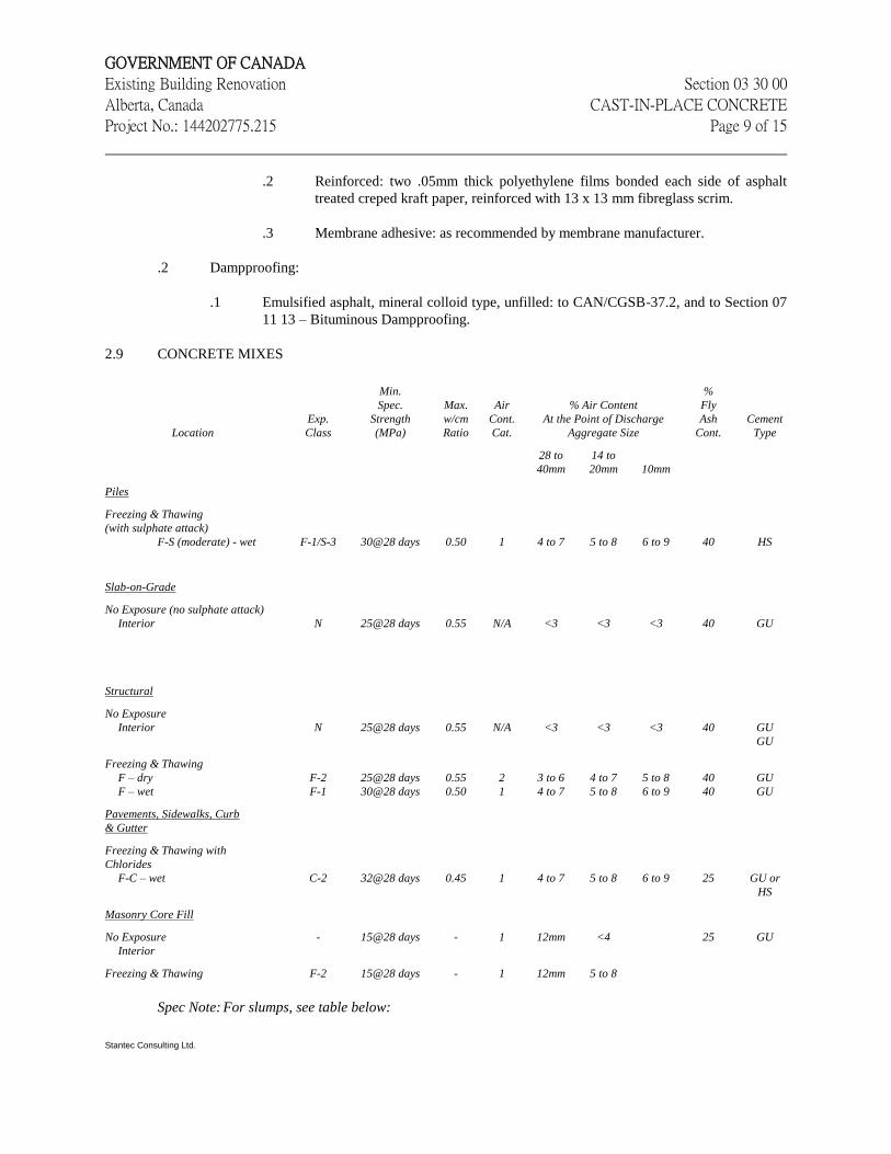
GOVERNMENT OF CANADA
Existing Building Renovation Section 03 30 00
Alberta, Canada CAST-IN-PLACE CONCRETE
Project No.: 144202775.215 Page 9 of 15
Stantec Consulting Ltd.
.2 Reinforced: two .05mm thick polyethylene films bonded each side of asphalt
treated creped kraft paper, reinforced with 13 x 13 mm fibreglass scrim.
.3 Membrane adhesive: as recommended by membrane manufacturer.
.2 Dampproofing:
.1 Emulsified asphalt, mineral colloid type, unfilled: to CAN/CGSB-37.2, and to Section 07
11 13 – Bituminous Dampproofing.
2.9 CONCRETE MIXES
Location
Exp.
Class
Min.
Spec.
Strength
(MPa)
Max.
w/cm
Ratio
Air
Cont.
Cat.
% Air Content
At the Point of Discharge
Aggregate Size
%
Fly
Ash
Cont.
Cement
Type
28 to
40mm
14 to
20mm
10mm
Piles
Freezing & Thawing
(with sulphate attack)
F-S (moderate) - wet
F-1/S-3
30@28 days
0.50
1
4 to 7
5 to 8
6 to 9
40
HS
Slab-on-Grade
No Exposure (no sulphate attack)
Interior
N
25@28 days
0.55
N/A
<3
<3
<3
40
GU
Structural
No Exposure
Interior
N
25@28 days
0.55
N/A
<3
<3
<3
40
GU
GU
Freezing & Thawing
F – dry
F – wet
F-2
F-1
25@28 days
30@28 days
0.55
0.50
2
1
3 to 6
4 to 7
4 to 7
5 to 8
5 to 8
6 to 9
40
40
GU
GU
Pavements, Sidewalks, Curb
& Gutter
Freezing & Thawing with
Chlorides
F-C – wet
C-2
32@28 days
0.45
1
4 to 7
5 to 8
6 to 9
25
GU or
HS
Masonry Core Fill
No Exposure
Interior
Freezing & Thawing
-
F-2
15@28 days
15@28 days
-
-
1
1
12mm
12mm
<4
5 to 8
25
GU
Spec Note: For slumps, see table below:
GOVERNMENT OF CANADA
Existing Building Renovation Section 03 30 00
Alberta, Canada CAST-IN-PLACE CONCRETE
Project No.: 144202775.215 Page 10 of 15
Stantec Consulting Ltd.
Component Slump (mm)
Piles
S.O.G.
Architectural
Pavements, Parking Decks and Toppings
Masonry Grout
80 – 125
50 – 90
50 – 90
20 – 60
200 - 250
.1 The Contractor is to design all concrete mixes and is to pay for all costs associated with the
development of the mix designs.
.2 The Contractor is to supply concrete in accordance with CSA-A23.1, except that the additional
requirements of this specification are also to apply.
.3 Only such materials or blends of materials that will result in a uniform colour of exposed surfaces
are to be used.
.4 Concrete mixes that will be placed by concrete pump are to be designed for pumping.
.5 In the event that slump and/or air content are outside the specified tolerance range as determined
by the inspection and testing firm appointed by the Contractor, the Engineer may, at his sole
discretion, accept a proposal for one adjustment of the deficient condition as an alternate to
rejection.
.6 The maximum placement temperature of 18C is specified to ensure that concrete temperatures do
not exceed 60C during curing, that temperature gradients do not exceed 20C total and
temperature rise or drop do not exceed a maximum heating and cooling rate of 2C/hour. The
maximum placement temperature may be increased to 25C provided the above temperature
requirements are met.
.7 Supply “Controlled Concrete” in accordance with CSA-A23.1 with properties as noted on the
drawings in the following table:
.8 Water-soluble chloride ion content in exposure class C-XL and C-1 concrete before exposure is
not to exceed 0.06% by mass of cementing material.
.9 Aggregate size specified is maximum nominal allowance. Contractor may use smaller nominal
size to ease placing. Air content may have to be increased for smaller aggregate to meet exposure
class requirements.
.10 Minimum cement content:
.1 380 kg/m3 (total cementitious material) for Type A.
.11 Maximum fly ash content as a percentage of the total cementitious material:
.1 Concrete with exposure classes C-XL, C-1 and C-2: Maximum 15% fly ash.
.2 Concrete with exposure classes C-3, C-4 and F-1: Maximum 25% fly ash.
.3 Concrete with exposure classes F-2 and N: Maximum 40% fly ash.

GOVERNMENT OF CANADA
Existing Building Renovation Section 03 30 00
Alberta, Canada CAST-IN-PLACE CONCRETE
Project No.: 144202775.215 Page 11 of 15
Stantec Consulting Ltd.
.12 Slump: No slumps outside the range of maximum or minimum will be permitted without written
permission of the Engineer. Supply slumps at 20 mm below maximum.
.13 Air Content: All mix types with exposure classifications to be air-entrained in accordance with the
above table and CSA-A23.1.
.14 Use a water-reducing agent in all concrete.
.15 Use accelerating admixtures in cold weather only when approved by the Engineer. If approved,
the use of admixtures will not relax cold weather placement requirements.
.16 Do not use calcium chloride or admixtures containing calcium chloride.
.17 Use set-retarding admixtures during hot weather with written approval of the Engineer
.18 Use all admixtures in strict accordance with the manufacturer’s recommendations.
.19 Do not use non-specified admixtures unless approved in writing by the Engineer. Where
superplasticizers are thus approved, ensure mix designs are correctly adjusted for placement,
strength, durability and air content requirements.
.20 Documentation indicating the compatibility of the water reducing admixture, the air entraining
admixture, the superplasticizing admixture (if any), the cement, the silica fume (if any) and the fly
ash (if any) is to be submitted upon request with the mix design for review by the Engineer.
2.10 GROUT MIXES
.1 Epoxy grout: Non-shrink, high strength compound consisting of epoxy resins, hardeners and non-
metallic aggregate for exterior use. Use for Pre-mixed in strict accordance with the
manufacturer’s instructions to obtain a minimum compressive strength of 50 MPa in 28 days.
.2 Dry pack grout: Non-shrink compound consisting of non-metallic aggregate and water. Mixed
with sufficient water for the mixture to make a sound, solid pack and capable of developing
compressive strength of 50 MPa at 28 days.
.3 Non-shrink grout: Pre-mixed compound consisting of non-metallic aggregate, cement, water
reducing and plasticizing agents. Pre-mixed in strict accordance with manufacturer’s instructions to
obtain a minimum compressive strength of 16 MPa in 24 hours and 50 MPa in 28 days. Acceptable
non-shrink grouts:
.1 Masterflow 713 Grout.
.2 Master Builders Set Non-Shrink Grout.
.3 Sika Grout 212.
.4 Sternson M-Bed Standard Grout.
.5 CPD Non-Shrink Grout.
.6 Sonogrout.
GOVERNMENT OF CANADA
Existing Building Renovation Section 03 30 00
Alberta, Canada CAST-IN-PLACE CONCRETE
Project No.: 144202775.215 Page 12 of 15
Stantec Consulting Ltd.
Part 3 Execution
3.1 GENERAL
.1 Perform cast-in-place concrete work in accordance with requirements of CSA-A23.1 unless
indicated otherwise on the drawings.
.2 Verify top of pile elevations. Cut down piles or increase lengths as required to the proper
elevations. Ensure piles project into grade beams and pile caps as indicated on drawings.
.3 Remove all loose concrete from tops of piles. Ensure tops of piles are clean and of sound concrete.
3.2 PLACING CONCRETE
.1 Notify Engineer and testing firm a minimum of 48 hours prior to commencement of any concrete
placement. Allow time for corrective work for areas of unusual formwork and congested
reinforcement.
.2 Notify geotechnical engineer to inspect and verify all soil conditions and bearing pressures of all
foundations prior to placing concrete for mudslabs or foundations.
.3 Do not place concrete against frozen ground, frozen concrete or frosted forms.
.4 In locations where new concrete is doweled to existing work, drill holes in existing concrete, insert
steel dowels and set solidly with non-shrink grout or as specified on the drawings. The holes for
the inserts are to be thoroughly cleaned.
.5 Ensure all hardware and all other items to be cast into concrete are placed securely and will not
cause undue hardship in placing concrete.
.6 Ensure reinforcement, inserts, embedded parts, formed expansion and contraction joints and other
critical items are not disturbed during concrete placement.
.7 Revise, re-seat and correct improperly positioned reinforcing hardware and other embedded items
immediately before concrete placement.
.8 Ensure specified concrete cover around reinforcing is maintained.
.9 Place concrete reinforcing in accordance with Section 03 20 00 – Concrete Reinforcing.
.10 During concrete operations:
.1 Development of cold joints not allowed.
.2 Ensure concrete delivery and handling facilities placing with minimum of rehandling, and
without damage to existing structure or Work.
.11 Prior to placing of concrete, obtain Engineer’s approval of proposed method for protection of
concrete during placing and curing.
GOVERNMENT OF CANADA
Existing Building Renovation Section 03 30 00
Alberta, Canada CAST-IN-PLACE CONCRETE
Project No.: 144202775.215 Page 13 of 15
Stantec Consulting Ltd.
.12 Protect previous Work from staining.
.13 Clean and remove stains prior to application for concrete finishes.
3.3 CONSTRUCTION
.1 Do not place concrete older than 2 hours from batch time.
.2 Do not add water after batching unless in strict accordance with CSA-A23.1, and such that
concrete conforms with the specified mix design parameters.
.3 Place concrete and screed in accordance with the lines and levels indicated on the drawings.
.4 Place concrete in approximate horizontal layers such that each lift can be vibrated into the previous
lift.
.5 Maximum vertical free fall of concrete is not to exceed 1200 mm in unexposed work or 800 mm in
exposed work. Confine concrete with a suitable vertical drop pipe to prevent segregation.
.6 Place concrete directly into its final position in forms. Do not spread concrete with vibrators.
.7 Compact concrete thoroughly by mechanical vibrators. Ensure concrete is worked around
reinforcement, embedded items and into all areas and corners of forms.
.8 Use internal vibrators in all sections that are sufficiently large, and supplement with external type
in the event that satisfactory surfaces can not be obtained.
.9 Check and re-adjust formwork to required lines and levels during placement of concrete.
.10 Place concrete as a continuous operation, stopping only at construction joints.
.11 Allow a minimum of three days between adjacent concrete placements.
.12 Use cold weather concreting methods in accordance with CSA-A23.1 when the mean daily
temperature falls below 5°C, and use hot weather methods when the mean temperature rises above
25°C.
.13 Maintain accurate records of concrete placement. Record date, location of placement, quantity, air
temperature and test samples taken.
.14 Sleeves and inserts:
.1 Do not permit penetrations, sleeves, ducts, pipes or other openings to pass through joists,
beams, column capitals or columns, except where indicated or approved by Engineer.
.2 Where approved by Engineer set sleeves, ties, pipe hangers and other inserts and
openings as indicated or specified elsewhere.
.3 Sleeves and openings greater than 100 x 100 mm not indicated, must be reviewed by
Engineer.
GOVERNMENT OF CANADA
Existing Building Renovation Section 03 30 00
Alberta, Canada CAST-IN-PLACE CONCRETE
Project No.: 144202775.215 Page 14 of 15
Stantec Consulting Ltd.
.4 Do not eliminate or displace reinforcement to accommodate hardware. If inserts cannot be
located as specified, obtain approval of modifications from Engineer before placing of
concrete.
.5 Check locations and sizes of sleeves and openings shown on drawings.
.6 Set special inserts for strength testing as indicated and as required by non-destructive
method of testing concrete. Anchor bolts:
.7 Set anchor bolts to templates under supervision of appropriate trade prior to placing
concrete.
.8 Protect anchor bolt holes from water accumulations, snow and ice build-ups.
.9 Set bolts and fill holes with epoxy grout.
.10 Locate anchor bolts used in connection with expansion shoes, rollers and rockers with due
regard to ambient temperature at time of erection.
3.4 PLACING OF EXPOSED CONCRETE
.1 Do not place concrete from one end for full height of placement.
.2 Use sufficient vibration equipment and methods to ensure dense, smooth concrete lines and
surfaces free from bugholes, honeycombs and cold joints.
.3 Ensure vibrator penetrates each layer of fresh concrete to prevent stratification.
.4 In hot weather, use set retarding agents to prevent cold joints with permission of the Engineer.
3.5 FINISHING FLATWORK
.1 Refer to Section 03 35 00 for concrete floor finishes.
3.6 DEFECTIVE CONCRETE
.1 Immediately after removing forms, all concrete surfaces are to be inspected, and any imperfect
joints, voids, stone pockets or other defective areas as specified are to be reported to the Engineer
at once and repaired before the concrete is thoroughly dry. Defective areas are to be chipped away
to a depth of not less than 25 mm with the edges perpendicular to the surface. The area to be
repaired and a space at least 150 mm wide entirely surrounding it are to be wetted to a saturated
surface dry condition to prevent absorption of water from the repair material.
.2 The repair is to be made of the same material and of the same proportions as used for the concrete,
except that the coarse aggregate is to be omitted and cement added to match the colour of the
surrounding concrete. The amount of mixing water is to be as little as consistent with the
requirements for handling and placing. The mortar is to be re-tempered without the addition of
water by allowing it to stand for a period of one hour, during which time it is to be mixed with a
trowel to prevent setting.
GOVERNMENT OF CANADA
Existing Building Renovation Section 03 30 00
Alberta, Canada CAST-IN-PLACE CONCRETE
Project No.: 144202775.215 Page 15 of 15
Stantec Consulting Ltd.
.3 The repair material is to be thoroughly compacted into place and screeded off to leave the repair
slightly higher than the surrounding surface. It is then to be left undisturbed for a period of one to
two hours to permit initial shrinkage before being finally finished. The repair is then to be finished
to match the adjoining surface and cured to the requirements noted in this specification.
.4 Watertight structures with honeycombing or embedded debris are not acceptable. Remove and
replace concrete between construction joints.
.5 Report any shapes and lines outside the specified tolerances and repair or correct as directed by the
Engineer.
3.7 EXTERNAL FASTENING AND CORING
.1 Do not core concrete without prior written approval of the Engineer.
.2 Do not drill inserts or drive power actuated fasteners into structural concrete without prior written
approval of the Engineer.
3.8 CARBON MONOXIDE EQUIPMENT
.1 Do not place concrete for floor slabs if carbon monoxide producing equipment has been in
operation in the building or temporary enclosure during the 12 hours preceding the start of
concreting.
.2 Provide positive ventilation during the 12 hours preceding the start of concreting.
.3 Unless directly used for the concrete placing, do not operate carbon monoxide producing
equipment in the building or temporary enclosure during or within 24 hours after completing the
finishing of any floor slab section.
3.9 JOINT FILLERS
.1 Furnish filler for each joint in single piece for depth and width required for joint, unless otherwise
authorized by Engineer.
3.10 CLEANING
.1 Repair, remove and clean all drips and smears resulting from the work of this section on exposed,
finished surfaces or surfaces to be subsequently finished.
.2 Hose down sandblasted surfaces. Brush thoroughly with a stiff broom to remove all dust and loose
particles.
END OF SECTION

GOVERNMENT OF CANADA
Existing Building Renovation Section 04 05 00
Alberta, Canada COMMON WORK RESULTS FOR MASONRY
Project No.: 144202775.215 Page 1 of 8
1 General
1.1 RELATED REQUIREMENTS
.1 Section 04 05 12 - Masonry Mortar.
.2 Section 04 05 19 - Masonry Anchorage and Reinforcing.
.3 Section 04 22 00 - Concrete Unit Masonry.
1.2 REFERENCES
.1 CSA Group
.1 CAN/CSA-A23.1-14/A23.2-14, Concrete Materials and Methods of Concrete
Construction/Test Methods and Standard Practices for Concrete.
.2 CSA A165 Series-14, CSA Standards on Concrete Masonry Units (Consists of
A165.1, A165.2 and A165.3).
.3 CSA A179-14, Mortar and Grout for Unit Masonry.
.4 CSA-A370-14, Connectors for Masonry.
.5 CSA-A371-14, Masonry Construction for Buildings.
.6 CSA-A3000-13, Cementitious Materials Compendium.
.7 CSA S304-14, Design of Masonry Structures.
.8 CSA S304.1-04(R2010), Design of Masonry Structures.
.9 CAN/CSA-G30.18-09, Billet-Steel Bars for Concrete Reinforcement.
.2 International Masonry Industry All-Weather Council (IMIAC)
.1 Recommended Practices and Guide Specification for Cold Weather Masonry
Construction.
1.3 ADMINISTRATIVE REQUIREMENTS
.1 Pre-installation meetings: comply with Section 01 31 19 - Project Meetings. Conduct pre-
installation meeting one week prior to commencing work of this Section to:
.1 Verify project requirements, including mock-up requirements.
.2 Verify substrate conditions.
.3 Co-ordinate products, installation methods and techniques.
.4 Sequence work of related sections.
.5 Co-ordinate with other building subtrades.
.6 Review manufacturer's installation instructions.
.7 Review masonry cutting operations, methods and tools and determine worker
safety and protection from dust during cutting operations.
.8 Review warranty requirements.
.9 Review cutting, patching and alterations to existing masonry and tie ins to existing
masonry.
GOVERNMENT OF CANADA
Existing Building Renovation Section 04 05 00
Alberta, Canada COMMON WORK RESULTS FOR MASONRY
Project No.: 144202775.215 Page 2 of 8
.2 Sequencing: sequence with other work in accordance with Section 01 32 16.06 -
Construction Progress Schedule - Critical Path Method (CPM). Comply with
manufacturer's written recommendations for sequencing construction operations.
.3 Scheduling: schedule with other work in accordance with Section 01 32 16.06 -
Construction Progress Schedule - Critical Path Method (CPM).
1.4 ACTION AND INFORMATIONAL SUBMITTALS
.1 Submit in accordance with Section 01 33 00 - Submittal Procedures.
.2 Product Data:
.1 Submit manufacturer's instructions, printed product literature and data sheets for
masonry and include product characteristics, performance criteria, physical size,
finish and limitations.
.2 Submit 2 copies of WHMIS MSDS in accordance with Section 01 35 29.06 -
Health and Safety Requirements.
.3 Shop Drawings:
.1 Submit drawings stamped and signed by professional engineer registered or
licensed in Province of Alberta, Canada.
.2 Submit shop drawings detailing temporary bracing required, designed to resist
wind pressure and lateral forces during installation.
.4 Certificates: submit manufacturer's product certificates certifying materials comply with
specified requirements.
.5 Test and Evaluation Reports:
.1 Submit certified test reports in accordance with Section 01 29 83 - Payment
Procedures for Testing Laboratory Services.
.2 Test reports to certify compliance of masonry units and mortar ingredients with
specified performance characteristics and physical properties.
.3 Submit data for masonry units, in addition to requirements set out in referenced
CSA and ASTM Standards, indicating initial rates of absorption.
.6 Installer Instructions: provide manufacturer's installation instructions, including storage,
handling, safety and cleaning.
.7 Manufacturer's Reports: provide written reports prepared by manufacturer's on-site
personnel to include:
.1 Verification of compliance of work with Contract.
.2 Site visit reports providing detailed review of installation of work, and installed
work.
1.5 CLOSEOUT SUBMITTALS
GOVERNMENT OF CANADA
Existing Building Renovation Section 04 05 00
Alberta, Canada COMMON WORK RESULTS FOR MASONRY
Project No.: 144202775.215 Page 3 of 8
.1 Submit manufacturer's instructions for care, cleaning and maintenance of prefaced
masonry units for incorporation into manual specified in Section 01 78 00 - Closeout
Submittals.
1.6 EXTRA MATERIALS
.1 Submit manufacturer's instructions in accordance with Section 01 78 00 - Closeout
Submittals covering maintenance requirements and parts catalogue, with cuts and
identifying numbers.
1.7 DELIVERY, STORAGE AND HANDLING
.1 Deliver, store and handle materials in accordance with Section 01 61 00 - Common
Product Requirements and with manufacturer's written instructions.
.2 Delivery and Acceptance Requirements: deliver materials to site in original factory
packaging, labelled with manufacturer's name and address.
.3 Storage and Handling Requirements:
.1 Store materials off ground, in dry location and in accordance with manufacturer's
recommendations in clean, dry, well-ventilated area.
.2 Store and protect material from nicks, scratches, and blemishes.
.3 Keep materials dry until use.
.4 Store under waterproof cover on pallets or plank platforms held off ground by
means of plank or timber skids.
.5 Replace defective or damaged materials with new.
1.8 SITE CONDITIONS
.1 Ambient Conditions: assemble and erect components when temperatures are above 4
degrees C.
.2 Weather Requirements: to CAN/CSA-A371 and to IMIAC - Recommended Practices and
Guide Specifications for Cold Weather Masonry Construction.
.3 Cold weather requirements:
.1 To CAN/CSA-A371 with following requirements.
.1 Maintain temperature of mortar between 5 degrees C and 50 degrees C
until batch is used or becomes stable.
.2 Maintain ambient temperature of masonry work and it's constituent
materials between 5 degrees C and 50 degrees C and protect site from
windchill.
.3 Maintain temperature of masonry above 0 degrees C for minimum of 3
days, after mortar is installed.
.4 Preheat unheated wall sections in enclosure for minimum 72 hours above
10 degrees C, before applying mortar.
.2 Hot weather requirements:
GOVERNMENT OF CANADA
Existing Building Renovation Section 04 05 00
Alberta, Canada COMMON WORK RESULTS FOR MASONRY
Project No.: 144202775.215 Page 4 of 8
.1 Protect freshly laid masonry from drying too rapidly, by means of
waterproof, non-staining coverings.
.2 Keep masonry dry using waterproof, non-staining coverings that extend
over walls and down sides sufficient to protect walls from wind driven
rain, until masonry work is completed and protected by flashings or other
permanent construction.
.3 Spray mortar surface at intervals and keep moist for maximum of 3 days after
installation.
1.9 WARRANTY
.1 For Work in this Section, 12 months warranty period is extended to 24 months.
2 Products
2.1 MATERIALS
.1 Masonry materials are specified elsewhere in related Sections:
.1 Section 04 05 12 - Masonry Mortar.
.2 Section 04 05 19 - Masonry Anchorage and Reinforcing.
.3 Section 04 22 00 - Concrete Unit Masonry.
3 Execution
3.1 INSTALLERS
.1 Experienced and qualified masons to carry out erection, assembly and installation of
masonry work.
3.2 EXAMINATION
.1 Examine conditions, substrates and work to receive work of this Section.
.1 Co-ordinate with Section 01 71 00 - Examination and Preparation.
.2 Examine openings to receive masonry units. Verify opening size, location, and that
opening is square and plumb, and ready to receive work of this Section.
.1 Inform Departmental Representative of unacceptable conditions immediately
upon discovery.
.2 Proceed with installation after unacceptable conditions have been remedied and
after receipt of written approval from Departmental Representative.
.3 Verification of Conditions:
.1 Verify that:
.1 Substrate conditions which have been previously installed under other
sections or contracts, are acceptable for product installation in accordance
with manufacturer's instructions prior to installation of concrete block.
.2 Field conditions are acceptable and are ready to receive work.

GOVERNMENT OF CANADA
Existing Building Renovation Section 04 05 00
Alberta, Canada COMMON WORK RESULTS FOR MASONRY
Project No.: 144202775.215 Page 5 of 8
.3 Built-in items are in proper location, and ready for roughing into masonry
work.
.2 Commencing installation means acceptance of existing substrates.
3.3 PREPARATION
.1 Surface Preparation: prepare surface in accordance with manufacturer's written
recommendations and co-ordinate with Section 01 71 00 - Examination and Preparation.
.2 Establish and protect lines, levels, and coursing.
.3 Protect adjacent materials from damage and disfiguration.
3.4 INSTALLATION
.1 Do masonry work in accordance with CAN/CSA-A371 except where specified otherwise.
.2 Build masonry plumb, level, and true to line, with vertical joints in alignment, respecting
construction tolerances permitted by CAN/CSA-A371.
.3 Layout coursing and bond to achieve correct coursing heights, and continuity of bond
above and below openings, with minimum of cutting.
3.5 CONSTRUCTION
.1 Exposed masonry:
.1 Remove chipped, cracked, and otherwise damaged units, in accordance with
CAN/CSA-A165, in exposed masonry and replace with undamaged units.
.2 Jointing:
.1 Allow joints to set just enough to remove excess water, then tool with round
jointer to provide smooth, joints true to line, compressed, uniformly concave
joints where concave joints are indicated.
.2 Allow joints to set just enough to remove excess water, then rake joints uniformly
to 6 mm depth and compress with square tool to provide smooth, compressed,
raked joints of uniform depth where raked joints are indicated.
.3 Strike flush joints concealed in walls and joints in walls to receive plaster, tile,
insulation, or other applied material except paint or similar thin finish coating.
.4 Where new masonry ties into adjacent masonry, ensure joints in new masonry
align with joints in existing masonry. Tooth new masonry into existing masonry
to maintain continuity of the bond.
.3 Cutting:
.1 Cut out for electrical switches, outlet boxes, and other recessed or built-in objects.
.2 Make cuts straight, clean, and free from uneven edges.
GOVERNMENT OF CANADA
Existing Building Renovation Section 04 05 00
Alberta, Canada COMMON WORK RESULTS FOR MASONRY
Project No.: 144202775.215 Page 6 of 8
.4 Building-In:
.1 Build in items required to be built into masonry.
.2 Prevent displacement of built-in items during construction. Check plumb, location
and alignment frequently, as work progresses.
.3 Brace door jambs to maintain plumb. Fill spaces between jambs and masonry with
mortar.
.5 Support of loads:
.1 Use 20 MPa concrete to Section 03 30 00 - Cast-in-Place Concrete, where
concrete fill is used in lieu of solid units and to locations where concrete core fills
are indicated.
.2 Use concrete core fills to CAN/CSA-A179 where concrete core fills are used in
lieu of solid units.
.3 Install building paper below voids to be filled with concrete; keep paper 25 mm
back from faces of units.
.6 Provision for movement:
.1 Leave 6 mm space between top of non-load bearing walls and partitions and
structural elements. Do not use wedges.
.2 Built masonry to tie in with stabilizers, with provision for vertical movement.
.7 Loose steel lintels:
.1 Install loose steel lintels. Center over opening width.
.8 Control joints:
.1 Construct continuous control joints as indicated or as otherwise directed by the
Departmental Representative.
.9 Movement joints:
.1 Build-in continuous movement joints as indicated.
.10 Interface with other work:
.1 Cut openings in existing work as indicated.
.2 Openings in walls: reviewed and accepted by Departmental Representative.
.3 Make good existing work. Use materials to match existing.
3.6 SITE TOLERANCES
.1 Tolerances in notes to CAN/CSA-A371 apply.
3.7 EXISTING WORK ALTERATIONS
.1 Provide for making good and patching of work in existing building including cutting and
patching for Mechanical and Electrical trades, whenever required, in accordance with
good workmanship. Use materials to match existing.
GOVERNMENT OF CANADA
Existing Building Renovation Section 04 05 00
Alberta, Canada COMMON WORK RESULTS FOR MASONRY
Project No.: 144202775.215 Page 7 of 8
.2 Infill existing openings and install new lintels, doors and the like, in existing masonry
construction as indicated. Neatly and accurately saw cut existing masonry to
accommodate new construction.
.3 Patch and make good existing masonry where required to accommodate new construction,
and where damaged or disturbed due to work of this contract.
.4 Install new block jambs and lintels above new doors to match existing construction.
.5 Tooth all new infills into existing masonry and install infills to render them undetectable
in the walls.
3.1 FIELD QUALITY CONTROL
.1 Site Tests, Inspection:
.1 Perform field inspection and testing in accordance with Section 01 45 00 - Quality
Control.
.2 Notify inspection agency minimum of 72 hours in advance of requirement for
tests.
.2 Manufacturer's Services:
.1 Have manufacturer of products supplied under this Section review work involved
in handling, installation/application, and protection of its products, and submit
written reports in acceptable format to verify compliance of work with Contract.
.2 Manufacturer's field services: provide manufacturer's field services, consisting of
product use recommendations and periodic site visits for inspection of product
installation, in accordance with manufacturer's instructions.
.3 Schedule site visits to review work as installation is about to begin.
.4 Schedule site visits to review work at stages listed:
.1 After delivery and storage of products, and when preparatory work on
which work of this Section depends is complete, but before installation
begins.
.2 Twice during progress of work at 25% and 60% complete.
.3 Upon completion of work, after cleaning is carried out.
.5 Obtain reports within 3 days of review and submit immediately to Departmental
Representative.
3.2 CLEANING
.1 Progress Cleaning: clean in accordance with Section 01 74 11 - Cleaning.
.1 Leave Work area clean at end of each day.
3.3 PROTECTION
.1 Temporary Bracing:
.1 Provide temporary bracing of masonry work during and after erection until
permanent lateral support is in place.
.2 Bracing approved by Departmental Representative.
GOVERNMENT OF CANADA
Existing Building Renovation Section 04 05 00
Alberta, Canada COMMON WORK RESULTS FOR MASONRY
Project No.: 144202775.215 Page 8 of 8
.3 Brace masonry walls as necessary to resist wind pressure and lateral forces during
construction.
.2 Moisture Protection:
.1 Keep masonry dry using waterproof, non staining coverings that extend over walls
and down sides sufficient to protect walls from wind driven rain, until completed
and protected by flashing or other permanent construction.
.2 Cover completed and partially completed work not enclosed or sheltered with
waterproof covering at end of each work day. Anchor securely in position.
.3 Air Temperature Protection: protect completed masonry as recommended in 1.9,
SITE CONDITIONS.
END OF SECTION

GOVERNMENT OF CANADA
Existing Building Renovation Section 04 05 12
Alberta, Canada MASONRY MORTAR
Project No.: 144202775.215 Page 1 of 5
1 General
1.1 RELATED REQUIREMENTS
.1 Section 04 05 00 - Common Work Results for Masonry.
.2 Section 04 05 19 - Masonry Anchorage and Reinforcing.
.3 Section 04 22 00 - Concrete Unit Masonry.
1.2 REFERENCES
.1 CSA Group
.1 CAN/CSA-A23.1-14/A23.2-14, Concrete Materials and Methods of Concrete
Construction/Test Methods and Standard Practices for Concrete.
.2 CSA A179-14, Mortar and Grout for Unit Masonry.
.3 CAN/CSA-A371-14, Masonry Construction for Buildings.
.4 CSA-A3000-13, Cementitious Materials Compendium.
.2 International Masonry Industry All-Weather Council (IMIAC)
.1 Recommended Practices and Guide Specifications for Cold Weather Masonry
Construction.
1.3 ACTION AND INFORMATIONAL SUBMITTALS
.1 Submit in accordance with Section 01 33 00 - Submittal Procedures.
.2 Product Data:
.1 Submit manufacturer's instructions, printed product literature and data sheets for
masonry mortar and grout and include product characteristics, performance
criteria, physical size, finish and limitations.
.2 Submit 2 copies of WHMIS MSDS in accordance with Section 01 35 29.06 -
Health and Safety Requirements.
.3 Manufacturers' Instructions: submit manufacturer's installation instructions.
1.4 QUALITY ASSURANCE
.1 Test Reports: submit certified test reports including sand gradation tests in accordance
with CAN/CSA-A179 showing compliance with specified performance characteristics and
physical properties, and in accordance with Section 04 05 00 - Common Work Results for
Masonry.
.2 Certificates: submit product certificates signed by manufacturer certifying materials
comply with specified performance characteristics and criteria and physical requirements.
1.5 DELIVERY, STORAGE AND HANDLING

GOVERNMENT OF CANADA
Existing Building Renovation Section 04 05 12
Alberta, Canada MASONRY MORTAR
Project No.: 144202775.215 Page 2 of 5
.1 Deliver, store and handle materials in accordance with Section 01 61 00 - Common
Product Requirements and with manufacturer's written instructions.
.2 Delivery and Acceptance Requirements: deliver materials to site in original factory
packaging, labelled with manufacturer's name and address.
.3 Storage and Handling Requirements:
.1 Store materials off ground in dry location and in accordance with manufacturer's
recommendations in clean, dry, well-ventilated area.
.2 Store and protect masonry mortar from damage.
.3 Replace defective or damaged materials with new.
1.6 SITE CONDITIONS
.1 Ambient Conditions: maintain materials and surrounding air temperature to:
.1 Minimum 5 degrees C prior to, during, and 48 hours after completion of masonry
work.
.2 Maximum 32 degrees C prior to, during, and 48 hours after completion of
masonry work.
.2 Weather Requirements: CAN/CSA-A371 and International Masonry Industry All-Weather
Council (IMIAC) - Recommended Practices and Guide Specifications for Cold Weather
Masonry Construction.
2 Products
2.1 MATERIALS
.1 Use same brands of materials and source of aggregate for entire project.
.2 Cement:
.1 Portland Cement: to CAN/CSA-A3000, Type GU - General use hydraulic cement
(Type 10).
.2 Packaged Dry Combined Materials for mortar: to CAN/CSA-A179, Type N for
brick and concrete block veneer, type S to all interior concrete block and concrete
block backup walls.
.3 Aggregate: supplied by one supplier.
.1 Fine Aggregate: to CAN/CSA-A179, natural sand.
.4 Water: clean and potable.
.5 Lime: to CAN/CSA-A179, Type N.
2.2 MORTAR MIXES
.1 Mortar for interior concrete block: type S based on proportion specifications.
GOVERNMENT OF CANADA
Existing Building Renovation Section 04 05 12
Alberta, Canada MASONRY MORTAR
Project No.: 144202775.215 Page 3 of 5
2.3 MORTAR MIXING
.1 Use pre-blended, pre-coloured mortar prepackaged under controlled factory conditions.
Ingredients batching limitations to be within 1% accuracy.
.2 Mix mortar ingredients in accordance with CAN/CSA-A179 in quantities needed for
immediate use.
.3 Maintain sand uniformly damp immediately before mixing process.
.4 Do not use anti-freeze compounds including calcium chloride or chloride based
compounds.
.5 Do not add air entraining admixture to mortar mix.
.6 Use a batch type mixer in accordance with CAN/CSA-A179.
.7 Pointing mortar: prehydrate pointing mortar by mixing ingredients dry, then mix again
adding just enough water to produce damp unworkable mix that will retain its form when
pressed into ball. Allow to stand for not less than 1 hour no more than 2 hours then remix
with sufficient water to produce mortar of proper consistency for pointing.
.8 Re-temper mortar only within two hours of mixing, when water is lost by evaporation.
.9 Use mortar within 2 hours after mixing at temperatures of 32 degrees C, or 2-1/2 hours at
temperatures under 5 degrees C.
2.4 CONCRETE MIXES
.1 Bond Beams: concrete mix 10 to 12.5 MPa strength at 28 days; 200-250 mm slump;
premixed type in accordance with CSA A23.1/A23.2.
.2 Lintels: concrete mix 10 to 12.5 MPa strength at 28 days; 200-250 mm slump; premixed
type in accordance with CSA A23.1/A23.2.
2.5 MIX TESTS
.1 Testing Mortar Mix:
.1 Test mortar to requirements of Section 01 45 00 - Quality Control, and in
accordance with CAN/CSA-A179, for mortar based on property specification or
proportion specification. Test during construction for:
.1 Compressive strength.
.2 Consistency.
.3 Mortar aggregate ratio.
.4 Sand/cement ratio.
.5 Water content and water/cement ratio.
.6 Air content.

GOVERNMENT OF CANADA
Existing Building Renovation Section 04 05 12
Alberta, Canada MASONRY MORTAR
Project No.: 144202775.215 Page 4 of 5
.7 Splitting tensile strength.
.2 Testing Concrete Mix:
.1 Test concrete to requirements of Section 01 45 00 - Quality Control, and in
accordance with CAN/CSA-A179, for grout based on property specification. Test
during construction for:
.1 Compressive strength.
.2 Sand/cement ratio.
.3 Water content and water/cement ratio.
.4 Slump.
3 Execution
3.1 EXAMINATION
.1 Verification of Conditions: verify that conditions of substrate previously installed under
other Sections or Contracts are acceptable for masonry installation in accordance with
manufacturer's written instructions.
.1 Visually inspect substrate in presence of Departmental Representative.
.2 Inform Departmental Representative of unacceptable conditions immediately
upon discovery.
.3 Proceed with installation only after unacceptable conditions have been remedied
and after receipt of written approval to proceed from Departmental
Representative.
3.2 PREPARATION
.1 Plug clean-out holes with brick and block masonry units. Brace masonry for wet grout
pressure.
3.3 CONSTRUCTION
.1 Do masonry mortar and grout work in accordance with CAN/CSA-A179 except where
specified otherwise.
3.4 MIXING
.1 All pointing mortar can be mixed using a regular paddle mixer. Only electric motor mixers
are permissible. Mixers run on hydrocarbons are not permitted, due to fumes.
.2 Clean all mixing boards and mechanical mixing machine between batches.
.3 Mortar must be weaker than the units it is binding.
.4 Contractor to appoint one individual to mix mortar, for duration of project. In the event
that this individual must be changed, mortar mixing must cease until the new individual is
trained, and mortar mix is tested.
GOVERNMENT OF CANADA
Existing Building Renovation Section 04 05 12
Alberta, Canada MASONRY MORTAR
Project No.: 144202775.215 Page 5 of 5
3.5 MORTAR PLACEMENT
.1 Install mortar to manufacturer's instructions.
.2 Install mortar to requirements of CAN/CSA-A179.
.3 Remove excess mortar from grout spaces.
3.6 CONCRETE PLACEMENT
.1 Install concrete in accordance with manufacturer's instructions.
.2 Install concrete infill in accordance with CAN/CSA-A179.
.3 Work concrete into masonry cores and cavities to eliminate voids.
.4 Do not install concrete in lifts greater than 400 mm, without consolidating concrete by
rodding.
.5 Do not displace reinforcement while placing grout.
3.7 FIELD QUALITY CONTROL
.1 Site Tests, Inspection: in accordance with Section 04 05 00 - Common Work Results for
Masonry supplemented as follows:
.1 Test and evaluate mortar during construction in accordance with CAN/CSA-
A179.
.2 Test and evaluate concrete infill during construction to CAN/CSA-A179; test in
conjunction with masonry unit sections specified.
.2 Manufacturer's Field Services: in accordance with Section 04 05 00 - Common Work
Results for Masonry.
3.8 CLEANING
.1 Progress Cleaning: clean in accordance with Section 01 74 11 - Cleaning.
.1 Leave Work area clean at end of each day.
.2 Remove droppings and splashings using clean sponge and water.
.3 Clean masonry with low pressure clean water and soft natural bristle brush.
.4 Final Cleaning: upon completion remove surplus materials, rubbish, tools and equipment
in accordance with Section 01 74 11 - Cleaning.
GOVERNMENT OF CANADA
Existing Building Renovation Section 04 05 12
Alberta, Canada MASONRY MORTAR
Project No.: 144202775.215 Page 6 of 5
3.9 PROTECTION
.1 Cover completed and partially completed work not enclosed or sheltered with waterproof
covering at end of each work day. Anchor securely in position.
END OF SECTION
GOVERNMENT OF CANADA
Existing Building Renovation Section 04 05 19
Alberta, Canada MASONRY ANCHORAGE AND REINFORCING
Project No.: 144202775.215 Page 1 of 5
1 General
1.1 REFERENCES
.1 ASTM International
.1 ASTM A123/A123M-13: Standard Specification for Zinc (Hot-Dip Galvanized)
Coatings on Iron and Steel Products.
.2 ASTM A951/A951M-14: Standard Specification for Steel Wire for Masonry Joint
Reinforcement.
.3 ASTM A1011/A1011M-14: Standard Specification for Steel, Sheet and Strip,
Hot-Rolled, Carbon, Structural, High-Strength Low-Alloy and High-Strength
Low-Alloy with Improved Formability.
.2 CSA Group
.1 CAN/CSA-A23.1-14/A23.2-14: Concrete Materials and Methods of Concrete
Construction/Test Methods and Standard Practices for Concrete.
.2 CAN/CSA-A179-14, Mortar and Grout for Unit Masonry.
.3 CAN/CSA-A370-14, Connectors for Masonry.
.4 CAN/CSA-A371-14, Masonry Construction for Buildings.
.5 CSA G30.18-09, Carbon Steel Bars for Concrete Reinforcement.
.8 CSA S304-14: Design of Masonry Structures.
.9 CSA S304.1-04(R2010): Design of Masonry Structures.
.3 Reinforcing Steel Institute of Canada (RSIC)
.1 Reinforcing Steel Manual of Standard Practice, 2004.
1.2 ACTION AND INFORMATIONAL SUBMITTALS
.1 Submit in accordance with Section 01 33 00 - Submittal Procedures.
.2 Product Data:
.1 Submit manufacturer's instructions, printed product literature and data sheets for
anchorage and reinforcing materials and include product characteristics,
performance criteria, physical size, finish and limitations.
.3 Shop Drawings:
.1 Submit drawings stamped and signed by professional engineer registered or
licensed in Province of Alberta, Canada.
.2 Submit drawings detailing bar bending details, anchorage details lists and
placement drawings.
.3 On placement drawings, indicate sizes, spacing, location and quantities of
reinforcement and connectors.
.4 Manufacturers' Instructions: submit manufacturer's installation instructions.

GOVERNMENT OF CANADA
Existing Building Renovation Section 04 05 19
Alberta, Canada MASONRY ANCHORAGE AND REINFORCING
Project No.: 144202775.215 Page 2 of 5
1.3 QUALITY ASSURANCE
.1 Test Reports: submit certified test reports including sand gradation tests in accordance
with CAN/CSA-A179 showing compliance with specified performance characteristics and
physical properties, and in accordance with Section 04 05 00 - Common Work Results for
Masonry.
.2 Certificates: submit product certificates signed by manufacturer certifying materials
comply with specified performance characteristics and criteria and physical requirements.
1.4 SITE MEASUREMENTS
.1 Make site measurements necessary to ensure proper fit of members.
1.5 DELIVERY, STORAGE AND HANDLING
.1 Deliver, store and handle materials in accordance with Section 01 61 00 - Common
Product Requirements and with manufacturer's written instructions.
.2 Delivery and Acceptance Requirements: deliver materials to site in original factory
packaging, labelled with manufacturer's name and address.
.3 Storage and Handling Requirements:
.1 Store materials off ground in dry location and in accordance with manufacturer's
recommendations in clean, dry, well-ventilated area.
.2 Store and protect anchorage and reinforcing materials from damage.
.3 Replace defective or damaged materials with new.
2 Products
2.1 MATERIALS
.1 Bar reinforcement: Steel to CAN/CSA-A371 and CSA G30.18, Grade 300.
.2 Connectors: to CAN/CSA-A370 and CSA S304.1.
.3 Corrosion protection: to CSA S304.1, galvanized to CSA S304.1 and CAN/CSA-A370.
.4 Fasteners: installed post-construction:
.1 Screw Shields and Plugs: plastic or nylon, water-resistant install in mortar joints
or placed directly into solid masonry units.
.2 Bolts and Screws: size and type to suit application, locate where indicated.
.3 Nails: case-hardened cut or spiral nails, size and type to suit fastening application.
.4 Powder-Driven Fasteners: pin styles and lengths to suit fastening application in
accordance with manufacturers use, load and hold recommendations.
.5 Adhesives: epoxies, mastics and contact cements for fastening applications, use in
accordance with manufacturers' recommendations.
GOVERNMENT OF CANADA
Existing Building Renovation Section 04 05 19
Alberta, Canada MASONRY ANCHORAGE AND REINFORCING
Project No.: 144202775.215 Page 3 of 5
.5 Ties: hot dip galvanized to CAN/CSA-A370 Table 5.2 steel finish.
.1 Joint Reinforcement Ties: to CAN/CSA-A370:
.1 Single Wythe Joint Reinforcement: ladder type:
.1 Steel wire, hot dip galvanized: to ASTM A641, Class 3 after
fabrication.
.2 Cold drawn steel wire conforming to ASTM A82.
.6 Anchors: to CAN/CSA-A370:
.1 Conventional Anchors: type steel bolts with bent bar anchors or plate anchors or
through bolts, shape J or L, size and type to suit application.
.2 Wedge Anchors: expansion anchors type, sized to suit application.
.3 Sleeve Anchors: type sleeve and bolt, sized to suit application.
.7 Conventional Bolts:
.1 Bolts: to ASTM A36, bar stock shop threaded, bent bar anchors, J shaped.
.2 Plate anchors: steel to ASTM A36, weld square of circular steel plate
perpendicular to axis of steel bar threaded on opposite end.
.3 Through bolt rods: to ASTM A307 threaded rod or threaded ASTM A36 bar
stock.
2.2 FABRICATION
.1 Fabricate reinforcing in accordance with CSA A23.1/A23.2 and Reinforcing Steel Manual
of Standard Practice by the Reinforcing Steel Institute of Canada.
.2 Fabricate connectors in accordance with CAN/CSA-A370.
.3 Obtain Departmental Representative's approval for locations of reinforcement splices other
than shown on placing drawings.
.4 Upon approval of Departmental Representative, weld reinforcement in accordance with
CSA W186.
.5 Ship reinforcement and connectors, clearly identified in accordance with drawings.
2.3 SOURCE QUALITY CONTROL
.1 Upon request, provide Departmental Representative with certified copy of mill test report
of reinforcement steel and connectors, showing physical and chemical analysis, minimum
5 weeks prior to commencing reinforcement work.
.2 Upon request inform Departmental Representative of proposed source of material to be
supplied.
3 Execution
3.1 EXAMINATION
GOVERNMENT OF CANADA
Existing Building Renovation Section 04 05 19
Alberta, Canada MASONRY ANCHORAGE AND REINFORCING
Project No.: 144202775.215 Page 4 of 5
.1 Verification of Conditions: verify that conditions of substrate previously installed under
other Sections or Contracts are acceptable for anchorage and reinforcing materials
installation in accordance with manufacturer's written instructions.
.1 Visually inspect substrate in presence of Departmental Representative.
.2 Inform Departmental Representative of unacceptable conditions immediately
upon discovery.
.3 Proceed with installation only after unacceptable conditions have been remedied
and after receipt of written approval to proceed from Departmental
Representative.
3.2 PREPARATION
.1 Direct and coordinate placement of metal anchors for masonry supplied to other Sections.
3.3 INSTALLATION
.1 Supply and install masonry connectors and reinforcement in accordance with CAN/CSA-
A370, CAN/CSA-A371, CSA A23.1/A23.2 and CSA S304.1 unless indicated otherwise.
.2 Prior to placing concrete and mortar, obtain Departmental Representative's approval of
placement of reinforcement and connectors.
.3 Supply and install additional reinforcement to masonry as indicated.
3.4 BONDING AND TYING
.1 Install unit, adjustable, single wythe joint reinforcement where indicated and in
accordance with CAN/CSA-A370 and CAN/CSA-A371 and manufacturer's instructions.
.1 Install horizontal joint reinforcement 400 mm on centre.
.2 Place masonry joint reinforcement in first and second horizontal joints above and
below openings. Extend minimum 400 mm each side of opening.
.3 Place joint reinforcement continuous in first and second joint below top of walls.
.4 Lap joint reinforcement ends minimum 150 mm.
.5 Connect joint corners and intersections with strap anchors 400 mm on centre.
3.5 REINFORCED LINTELS AND BOND BEAMS
.1 Reinforce masonry beams, masonry lintels and bond beams as indicated.
.2 Place and grout reinforcement in accordance with CSA S304.1, CAN/CSA-A371, and
CAN/CSA-A179.
.3 Support and position reinforcing bars in accordance with CAN/CSA-A371.
3.6 CONCRETE INFILL
GOVERNMENT OF CANADA
Existing Building Renovation Section 04 05 19
Alberta, Canada MASONRY ANCHORAGE AND REINFORCING
Project No.: 144202775.215 Page 5 of 5
.1 Install concrete infill into masonry in accordance with CSA S304.1, CAN/CSA-A371 and
CAN/CSA-A179 and as indicated.
3.7 ANCHORS
.1 Supply and install metal anchors in accordance with CAN/CSA-A370 and CAN/CSA-
A371.
3.8 LATERAL SUPPORT AND ANCHORAGE
.1 Supply and install lateral support and anchorage in accordance with CSA S304.1 and as
indicated.
3.9 MOVEMENT JOINTS
.1 Reinforcement will not be continuous across movement joints unless otherwise indicated.
3.10 FIELD BENDING
.1 Do not field bend reinforcement and connectors except where indicated or authorized by
Departmental Representative.
.2 When field bending is authorized, bend without heat, applying a slow and steady pressure.
.3 Replace bars and connectors which develop cracks or splits.
3.11 FIELD QUALITY CONTROL
.1 Site inspections in accordance with Section 04 05 00 - Common Work Results for
Masonry.
.2 Obtain Departmental Representative approval of placement of reinforcement and
connectors, prior to placing concrete infill.
3.12 FIELD TOUCH-UP
.1 Touch up damaged and cut ends of epoxy coated or galvanized reinforcement steel and
connectors with compatible finish to provide continuous coating.
3.13 CLEANING
.1 Progress Cleaning: clean in accordance with Section 01 74 11 - Cleaning.
.1 Leave Work area clean at end of each day.
.2 Final Cleaning: upon completion remove surplus materials, rubbish, tools and equipment
in accordance with Section 01 74 11 - Cleaning.

GOVERNMENT OF CANADA
Existing Building Renovation Section 04 05 19
Alberta, Canada MASONRY ANCHORAGE AND REINFORCING
Project No.: 144202775.215 Page 6 of 5
END OF SECTION
GOVERNMENT OF CANADA
Existing Building Renovation Section 04 22 00
Alberta, Canada CONCRETE UNIT MASONRY
Project No.: 144202775.215 Page 1 of 6
1 General
1.1 REFERENCES
.1 ASTM International
.1 ASTM E336-11, Standard Test Method for Measurement of Airborne Sound
Attenuation Between Rooms in Buildings.
.2 CSA Group
.1 CAN/CSA-A165 Series-14, CSA Standards on Concrete Masonry Units consists:
A165.1, A165.2, A165.3.
.2 CAN/CSA-A371-14, Masonry Construction for Buildings.
.3 CSA S304.1-04(R2010), Design of Masonry Structures.
.3 South Coast Air Quality Management District (SCAQMD)
.1 SCAQMD Rule 1168-05, Adhesive and Sealant Applications.
.4 Underwriters Laboratories of Canada (ULC)
.1 CAN/ULC-S101-14, Standard Methods of Fire Endurance Tests of Building
Construction and Materials.
1.2 ACTION AND INFORMATIONAL SUBMITTALS
.1 Submit in accordance with Section 01 33 00 - Submittal Procedures.
.2 Product Data:
.1 Submit manufacturer's instructions, printed product literature and data sheets for
concrete masonry units and include product characteristics, performance criteria,
physical size, finish and limitations.
1.3 QUALITY ASSURANCE
.1 Test Reports: submit certified test reports including sand gradation tests in accordance
with CAN/CSA-A179 showing compliance with specified performance characteristics and
physical properties, and in accordance with Section 04 05 00 - Common Work Results for
Masonry.
.2 Certificates: submit product certificates signed by manufacturer certifying materials
comply with specified performance characteristics and criteria and physical requirements.
1.4 DELIVERY, STORAGE AND HANDLING
.1 Deliver, store and handle materials in accordance with Section 01 61 00 - Common
Product Requirements and with manufacturer's written instructions.
GOVERNMENT OF CANADA
Existing Building Renovation Section 04 22 00
Alberta, Canada CONCRETE UNIT MASONRY
Project No.: 144202775.215 Page 2 of 6
.2 Delivery and Acceptance Requirements: deliver materials to site in original factory
packaging, labelled with manufacturer's name and address.
.1 Offload concrete unit masonry packages using equipment that will not damage the
surfaces.
.2 Do not use brick tongs to move or handle masonry.
.3 Storage and Handling Requirements:
.1 Store materials off ground in dry location and in accordance with manufacturer's
recommendations in clean, dry, well-ventilated area.
.2 Do not double stack cubes of concrete unit masonry.
.3 Cover masonry units with non-staining waterproof membrane covering.
.4 Allow air circulation around units.
.5 Installation of wet or stained masonry units is prohibited.
.6 Keep concrete unit masonry in individual cardboard packaging provided by
manufacturer until units are ready to be installed.
.7 Store and protect concrete unit masonry from nicks, scratches, and blemishes.
.8 Replace defective or damaged materials with new.
2 Products
2.1 MATERIALS
.1 Standard concrete block units: to CAN/CSA-A165 Series (CAN/CSA-A165.1) .
.1 Facet Designation:
.1 Units exposed to view: Hollow concrete blocks to have a facet
designation H/15/C/M. Solid concrete block to have facet designation
S/15/C/M.
.2 Units unexposed to view: Hollow concrete blocks to have a facet
designation H/15/C/O. Solid concrete block to have facet designation
S/15/C/O.
.2 Dimensions Nominal:
.1 Concrete block: 200 mm wide (unless noted otherwise) x 200 mm high x
400 mm long.
.3 Special shapes: provide square edge except to exposed corner use bull-nosed
block and to wall ends, door openings and the like, use double bull-nosed units.
Provide purpose-made shapes for lintels, beams and bond beams. Provide
additional special shapes as indicated.
.2 Fire rated concrete block units: to CAN/CSA-A165 Series (CAN/CSA-A165.1) as
modified below.
.1 Classification: H/15/B/M except as modified by fire resistance requirements
specified below.
.2 Fire resistant characteristics: aggregate used in units and equivalent thickness of
units to the Alberta Building Code 2014 and National Building Code of Canada
GOVERNMENT OF CANADA
Existing Building Renovation Section 04 22 00
Alberta, Canada CONCRETE UNIT MASONRY
Project No.: 144202775.215 Page 3 of 6
2010, and in accordance with CAN/ULC-S101, for fire-resistance ratings
indicated.
.3 Size: modular.
.4 Special shapes: provide square to all locations except bull- nosed units for
exposed corners and double bullnosed to door openings. Provide purpose-made
shapes for lintels and bond beams and provide additional shapes as indicated.
2.2 REINFORCEMENT
.1 Reinforcement in accordance with Section 04 05 19 - Masonry Anchorage and
Reinforcing.
2.3 CONNECTORS
.1 Connectors in accordance with Section 04 05 19 - Masonry Anchorage and Reinforcing.
2.4 MORTAR MIXES
.1 Mortar and mortar mixes in accordance with Section 04 05 12 - Masonry Mortar.
2.5 CONCRETE INFILL MIXES
.1 Concrete infill mixes in accordance with Section 04 05 12 - Masonry Mortar.
2.6 CLEANING COMPOUNDS
.1 Use low VOC products.
.2 Compatible with substrate and acceptable to masonry manufacturer for use on products.
.3 Cleaning compounds compatible with concrete unit masonry and in accordance with
manufacturer's written recommendations and instructions.
2.7 TOLERANCES
.1 Tolerances for standard concrete unit masonry tolerances in accordance with CAN/CSA-
A165.1, supplemented as follows:
.1 Maximum variation between units within specific job lot not to exceed 2 mm.
.2 No parallel edge length, width or height dimension for individual unit to differ by
more than 2 mm.
.3 Out of square tolerance not to exceed 2 mm.
3 Execution
3.1 EXAMINATION

GOVERNMENT OF CANADA
Existing Building Renovation Section 04 22 00
Alberta, Canada CONCRETE UNIT MASONRY
Project No.: 144202775.215 Page 4 of 6
.1 Verification of Conditions: verify that conditions of substrate previously installed under
other Sections or Contracts are acceptable for concrete unit masonry installation in
accordance with manufacturer's written instructions.
.1 Visually inspect substrate in presence of Departmental Representative.
.2 Inform Departmental Representative of unacceptable conditions immediately
upon discovery.
.3 Proceed with installation only after unacceptable conditions have been remedied
and after receipt of written approval to proceed from Departmental
Representative.
3.2 PREPARATION
.1 Protect adjacent finished materials from damage due to masonry work.
3.3 INSTALLATION
.1 Concrete block units:
.1 Bond: running or as otherwise required to match existing.
.2 Coursing height: 200 mm for one block and one joint.
.3 Jointing: concave where exposed or where paint or other finish coating is
specified.
.2 Special Shapes:
.1 Install special units to form corners, returns, offsets, reveals and indents without
cut ends being exposed and without losing bond or module.
.2 Install reinforced concrete block lintels over openings in masonry where steel or
reinforced concrete lintels are not indicated.
.3 End bearing: not less than 200 mm.
.4 Install special shaped units including site cut units.
3.4 REINFORCEMENT
.1 Install reinforcing in accordance with Section 04 05 19 - Masonry Anchorage and
Reinforcing .
3.5 CONNECTORS
.1 Install connectors in accordance with Section 04 05 19 - Masonry Anchorage and
Reinforcing.
3.6 MORTAR PLACEMENT
.1 Place mortar in accordance with Section 04 05 12 - Masonry Mortar.
3.7 CONCRETE INFILL PLACEMENT
.1 Place concrete infill in accordance with Section 04 05 12 - Masonry Mortar.
GOVERNMENT OF CANADA
Existing Building Renovation Section 04 22 00
Alberta, Canada CONCRETE UNIT MASONRY
Project No.: 144202775.215 Page 5 of 6
3.8 CONSTRUCTION
.1 Cull out masonry units, in accordance with CAN/CSA-A165 and reviewed and accepted
range of colour samples, with chips, cracks, broken corners, excessive colour and texture
variation.
.2 Build in miscellaneous items such as bearing plates, steel angles, bolts, anchors, inserts,
sleeves and conduits.
.3 Construct masonry walls using running bond unless otherwise noted.
.4 Build around frames previously set and braced. Fill behind hollow frames within masonry
walls with mortar or grout and embed anchors.
.5 Fit masonry closely against electrical and plumbing outlets so collars, plates and covers
overlap and conceal cuts.
.6 Install movement joints and keep free of mortar where indicated.
.7 Hollow Units: spread mortar setting bed from outside edge of face shells. Gauge amount
of mortar on top and end of unit to create full joints, equivalent to shell thickness. Avoid
excess mortar.
.8 Solid Units: apply mortar over entire vertical and horizontal surfaces. Avoid bridging of
airspace between brick veneer and backup wall with mortar.
.9 Ensure compacted head joints. Use full or face-shell joint as indicated.
.10 Tamp units firmly into place.
.11 Do not adjust masonry units after mortar has set. Where resetting of masonry is required,
remove, clean and reset units in new mortar.
.12 Tool exposed joints concave; strike concealed joints flush.
.13 After mortar has achieved initial set up, tool joints.
.14 Do not interrupt bond below or above openings.
3.9 REPAIR/RESTORATION
.1 Upon completion of masonry, fill holes and cracks, remove loose mortar and repair
defective work.
3.10 FIELD QUALITY CONTROL
.1 Site Tests, Inspection: in accordance with Section 04 05 00 - Common Work Results for
Masonry supplemented as follows:
GOVERNMENT OF CANADA
Existing Building Renovation Section 04 22 00
Alberta, Canada CONCRETE UNIT MASONRY
Project No.: 144202775.215 Page 6 of 6
.1 Concrete masonry units will be sampled and tested by independent testing agency
appointed and paid by Departmental Representative in accordance with CSA
S304.1.
.2 Noise reduction between two rooms will be tested by independent testing agency
appointed and paid by Departmental Representative in accordance with ASTM
E336.
.3 Notify inspection agency minimum of 24 hours in advance of requirement for
tests.
.2 Manufacturer's Field Services: in accordance with Section 04 05 00 - Common Work
Results for Masonry.
3.11 CLEANING
.1 Progress Cleaning: clean in accordance with Section 01 74 11 - Cleaning.
.1 Leave Work area clean at end of each day.
.2 Standard Concrete Unit Masonry:
.1 Allow mortar droppings on masonry to partially dry then remove by
means of trowel, followed by rubbing lightly with small piece of block.
Clean wall surface with suitable brush or burlap.
.3 Architectural Concrete Unit Masonry:
.1 Allow mortar droppings on masonry to partially dry then remove by
means of trowel, followed by rubbing lightly with small piece of block.
Clean wall surface with suitable brush or burlap.
.2 Final Cleaning: upon completion remove surplus materials, rubbish, tools and equipment
in accordance with Section 01 74 11 - Cleaning.
3.12 PROTECTION
.1 Brace and protect concrete unit masonry in accordance with Section 04 05 00 - Common
Work Results for Masonry.
END OF SECTION
GOVERNMENT OF CANADA
Existing Building Renovation Section 05 50 00
Alberta, Canada METAL FABRICATIONS
Project No.: 144202775.215 Page 1 of 9
1 General
1.1 RELATED REQUIREMENTS
.1 Section 09 91 23 - Interior Painting
1.2 REFERENCES
.1 ASME Standards:
.1 ASME B18.6.3: Machine Screws and Machine Screw Nuts.
.2 ASME B18.6.7M: Metric Machine Screws.
.3 ASME B18.2.1: Square and Hex Bolts and Screws, Inch Series.
.4 ASME B18.2.3.8M: Metric Hex Lag Screws.
.5 ASME B18.6.1: Wood Screws, Inch Series.
.2 ASTM International:
.1 ASTM A36/A36M-14: Standard Specification for Carbon Structural Steel.
.2 ASTM A108-13: Steel Bars, Carbon, Cold-Finished, Standard Quality.
.3 ASTM A123/A123M-13: Standard Specification for Zinc (Hot-Dip Galvanized)
Coatings on Iron and Steel Products.
.4 ASTM A283/A283M-13: Standard Specification for Low and Intermediate
Tensile Strength Carbon Steel Plates.
.5 ASTM A307-14: Standard Specification for Carbon Steel Bolts and Studs,
60,000 PSI Tensile Strength.
.6 ASTM A325-14: Standard Specification for Structural Bolts, Steel, Heat Treated,
120/105 ksi Minimum Tensile Strength.
.7 ASTM A325M-14: Standard Specification for Structural Bolts, Steel, Heat
Treated, 120/105 ksi Minimum Tensile Strength [Metric].
.8 ASTM A385/A385M-11e1: Standard Practice for Providing High-Quality Zinc
Coatings (Hot-Dip).
.9 ASTM A490-14a: Standard Specification for Structural Bolts, Alloy Steel, Heat
Treated, 150 ksi Minimum Tensile Strength.
.10 ASTM A490M-14a: Standard Specification for High-Strength Steel Bolts,
Classes 10.9 and 10.9.3, for Structural Steel Joints (Metric).
.11 ASTM A563M-15: Standard Specification for Carbon and Alloy Steel Nuts
[Metric].
.12 ASTM A563-07(2013): Standard Specification for Carbon and Alloy Steel Nuts.
.13 ASTM A780/A780M-09(2015): Repair of Damaged Hot-Dipped Galvanized
Coatings.
.14 ASTM C645-14: Standard Specification for Nonstructural Steel Framing
Members.
.15 ASTM D6386-10: Standard Practice for Preparation of Zinc (Hot-Dip
Galvanized) Coated Iron and Steel Product and Hardware Surfaces for Painting.
.16 ASTM E488/E488M-10: Standard Test Methods for Strength of Anchors in
Concrete and Masonry Elements.
.17 ASTM F436-11: Standard Specification for Hardened Steel Washers.
.18 ASTM F436M-11: Standard Specification for Hardened Steel Washers [Metric].
GOVERNMENT OF CANADA
Existing Building Renovation Section 05 50 00
Alberta, Canada METAL FABRICATIONS
Project No.: 144202775.215 Page 2 of 9
.19 ASTM F959M-13: Standard Specification for Compressible-Washer-Type Direct
Tension Indicators for Use With Structural Fasteners [Metric].
.20 ASTM F1554-07ae1: Standard Specification for Anchor Bolts, Steel, 36, 55, and
105-ksi Yield Strength.
.3 CGSB Standards:
.1 CAN/CGSB-1.40-97: Anticorrosive Structural Steel Alkyd Primer.
.2 CAN/CGSB-1.181-99: Ready-Mixed Organic Zinc-Rich Coating.
.4 CSA Standards:
.1 CAN/CSA-G40.20-13: General Requirements for Rolled or Welded Structural
Quality Steel.
.2 CAN/CSA-G40.21-13: Structural Quality Steels.
.3 CAN/CSA-S16-14: Design of Steel Structures.
.4 CSA W47.1-09(R2014): Certification of Companies for Fusion Welding of Steel.
.5 CSA W48-14: Filler Metals and Allied Materials for Metal Arc Welding.
.6 CSA W55.3-08(R2013): Certification of companies for resistance welding of steel
and aluminum.
.7 CSA W59-13: Welded Steel Construction (Metal-Arc Welding).
.8 CSA W178.1-14: Certification of Welding Inspection Organizations.
.9 CSA W178.2-14: Certification of Welding Inspectors (Developed in cooperation
with the Canadian Welding Bureau).
.5 Steel Structures Painting Council (SSPC): Systems and Specifications Manual, Volume 2.
.6 The Master Painters Institute (MPI)
.1 Architectural Painting Specification Manual - current edition.
1.3 ACTION AND INFORMATIONAL SUBMITTALS
.1 Submit in accordance with Section 01 33 00 - Submittal Procedures.
.2 Product Data:
.1 Submit manufacturer's instructions, printed product literature and data sheets for
sections, plates, pipe, tubing, bolts and include product characteristics,
performance criteria, physical size, finish and limitations.
.3 Shop Drawings:
.1 Submit drawings stamped and signed by professional engineer registered or
licensed in the Province of Alberta, Canada.
.2 Indicate materials, core thicknesses, finishes, connections, joints, method of
anchorage, number of anchors, supports, reinforcement, details, and accessories.
1.4 QUALITY ASSURANCE
.1 Test Reports: submit certified test reports showing compliance with specified performance
characteristics and physical properties.
GOVERNMENT OF CANADA
Existing Building Renovation Section 05 50 00
Alberta, Canada METAL FABRICATIONS
Project No.: 144202775.215 Page 3 of 9
.2 Certifications: submit product certificates signed by manufacturer certifying materials
comply with specified performance characteristics and criteria and physical requirements.
1.5 DELIVERY, STORAGE AND HANDLING
.1 Deliver, store and handle materials in accordance with Section 01 61 00 - Common
Product Requirements and with manufacturer's written instructions.
.2 Delivery and Acceptance Requirements: deliver materials to site in original factory
packaging, labelled with manufacturer's name and address.
.3 Storage and Handling Requirements:
.1 Store materials off ground in dry location and in accordance with manufacturer's
recommendations in clean, dry, well-ventilated area.
.2 Replace defective or damaged materials with new.
2 Products
2.1 MATERIALS
.1 Miscellaneous steel: to ASTM A36/A36M or to CAN/CSA-G40.20 and
CAN/CSA-G40.21, 300W yield strength.
.2 Hollow Structural Sections (HSS): to ASTM A36/A36M or to CAN/CSA-G40.20 and
CAN/CSA-G40.21, 350W yield strength, Class C.
.3 Structural steel: to ASTM A36/A36M or to CAN/CSA-G40.20 and CAN/CSA-G40.21,
350W yield strength.
.4 Welding materials: to CSA W59.
.5 Welding electrodes: to CSA W48 Series.
.6 Machine bolts: conforming to requirements of ASTM A307, Grade A.
.7 High tensile bolts for structural connections: conforming to the requirements of ASTM
A325/A325M.
.8 Nuts: conforming to ASTM A194/A194M, Grade 2H nuts.
.9 Washers: conforming to ASTM F436 and ASTM F436M; type 1 washers.
.10 Inserts: Hilti HSL-3, Hilti Kwik Bolt 3 or Hilti Kwik Bolt TZ, as required to suit
installation.
.11 Anchoring System: Hilti HIT system HIT H Y70 complete with mesh screen for concrete
and solid or concrete filled or grout filled masonry and hollow masonry.
GOVERNMENT OF CANADA
Existing Building Renovation Section 05 50 00
Alberta, Canada METAL FABRICATIONS
Project No.: 144202775.215 Page 4 of 9
.12 Shear Connectors: Nelson stud.
.13 Anchor bolts: conforming to ASTM F1554, Grade 36.
.14 Machine screws: conforming to ASME B18.6.3 (ASME B18.6.7M).
.15 Lag bolts: conforming to ASME B18.2.1 (ASME B18.2.3.8M).
.16 Wood screws: flat head, carbon steel,, conforming to ASME B18.6.1.
.17 Grout: non-shrink, non-metallic grout, factory packaged, non-staining, non-corrosive, non-
gaseous, grout complying to ASTM C1107, capable of developing compressive strength
of 50 MPa at 28 days. Provide grout specifically recommended by manufacturer for
interior applications.
2.2 FABRICATION
.1 Fabricate work square, true, straight and accurate to required size, with joints closely fitted
and properly secured.
.2 Use self-tapping shake-proof flat headed screws on items requiring assembly by screws or
as indicated.
.3 Where possible, fit and shop assemble work, ready for erection.
.4 Ensure exposed welds are continuous for length of each joint. File or grind exposed welds
smooth and flush.
2.3 FINISHES
.1 Shop galvanizing: hot dipped galvanizing with a minimum zinc coating of 600 g/m2 to
ASTM A123/A123M.
.2 Galvanizing Repair paint: high zinc dust content paint for re-galvanizing welds on steel,
complying with SSPC - Paint 20.
.3 Chromium plating: chrome on steel with plating sequence of 0.009 mm thickness of
copper 0.010 mm thickness of nickel and 0.0025 mm thickness of chromium.
.4 Shop coat primer:
.1 Interior: MPI- INT 5.1TT, Rust-Inhibitive Primer W.B.
.5 Zinc primer:
.1 Interior: MPI-INT 5.3N, W.B. Galvanized Primer.
2.4 ISOLATION COATING
.1 Isolate aluminum from following components, by means of bituminous paint:

GOVERNMENT OF CANADA
Existing Building Renovation Section 05 50 00
Alberta, Canada METAL FABRICATIONS
Project No.: 144202775.215 Page 5 of 9
.1 Dissimilar metals except stainless steel, zinc, or white bronze of small area.
.2 Concrete, mortar and masonry.
.3 Wood.
2.5 FABRICATION
.1 Perform work to the highest standard of modern shop and field practice, performed by
personnel specializing in this work. Accurately fit joints and intersecting members and
make in true planes, with adequate fastening. Fabricate work, plumb, true, square,
straight, level, accurate to sizes detailed, free from distortion or defects.
.2 File or grind and sand exposed welds, sharp edges and burrs, smooth and flush. All welds
must be ground smooth and flush with adjacent surfaces.
.3 Fabricate items in accordance with CAN/CSA-S16, of sizes and profiles indicated on
drawings and reviewed shop drawings, of sufficient size and strength to perform function
for which they are designed with joints neatly fitted and properly secured.
.4 Shop assemble in largest practical sections for delivery to site.
.5 Provide flush butt type hairline exposed joints where mechanically fastened.
.6 Ease exposed edges to a radius of approximately 1 mm, unless otherwise indicated. Form
bent-metal corners to smallest radius possible without casing grain separation or otherwise
impairing work.
.7 Provide flush countersunk screws or bolts to all exposed mechanical fastenings, located
consistent with design.
.8 Fabricate joints that will be exposed to weather in a manner to exclude water, or provide
weep holes where water may accumulate.
.9 Supply all components required for proper anchorage of metal fabrications. Fabricate
anchorage and related components of same material and finish as metal fabrication.
.10 Where work of other Sections is to be attached to Work of this Section, prepare work by
drilling and tapping holes as required to facilitate installation of such work.
.11 Verify all dimensions on site prior to fabrication.
.12 Supply all components in ample time for construction schedule as required, for proper
anchorage of metal fabrications. Fabricate anchorage and related components of same
material and finish as metal fabrication, unless indicated otherwise.
.13 Thoroughly clean all surfaces of rust, scale, grease and foreign matter prior to prime
painting or galvanizing.
2.6 WELDING
GOVERNMENT OF CANADA
Existing Building Renovation Section 05 50 00
Alberta, Canada METAL FABRICATIONS
Project No.: 144202775.215 Page 6 of 9
.1 Perform welding in accordance with the requirements of CSA W59.
.2 Perform welding inspection in accordance with the requirements of CSA W178.1 and
W178.2.
.3 Perform resistance welding to CSA W55.3.
.4 Weld joints to provide adequate strength and durability with jointing tight and flush.
Where it is necessary to weld components already galvanized, remove galvanizing for 50
mm around weld.
.5 Weld corners and seams to comply with the following:
.1 Use materials and methods that minimize distortion and develop strength and
corrosion resistance of base materials.
.2 Obtain fusion without undercut or overlap.
.3 Remove welding flux immediately.
.4 At exposed connections, finish exposed welds and surfaces smooth and blend so
no roughness shows after finishing and contour of welded surfaces matches that of
adjacent surfaces.
2.7 SURFACE PREPARATION
.1 Thoroughly clean and suitably pretreat steel prior to finishing.
.2 Remove loose mill scale, rust, oil, grease, dirt and other foreign matter using SSPC - SP
No. 6, Commercial Blast Cleaning, followed by SSPC - SP No. 1, solvent cleaning. Shop
prime all commercial blast cleaned surfaces immediately after cleaning operations.
.3 Grind and sand all sharp projections smooth.
2.8 FINISHES
.1 Shop paint items, all miscellaneous metal items with the exception of those which are to
be galvanized.
.2 Prepare galvanized steel surfaces to be painted, in accordance with ASTM D6386.
.3 Do prime painting to CSA-S16.
.4 Use primer as prepared by manufacturer without thinning or adding admixtures. Paint on
dry surfaces, free from rust, scale or grease. Do not paint when temperature is lower than
7C.
.5 After fabrication, clean, remove rust, mill scale, grease or extraneous material. Unless
specified otherwise, apply to all items, in shop, a full smooth coat of primer (see
materials). Work paint into corners and open spaces.
GOVERNMENT OF CANADA
Existing Building Renovation Section 05 50 00
Alberta, Canada METAL FABRICATIONS
Project No.: 144202775.215 Page 7 of 9
.6 Apply two (2) coats of primer to parts inaccessible after assembly.
.7 Apply one (1) coat of primer to steel surfaces except where encased in concrete. Leave
these surfaces clean and uncoated.
.8 Touch-up burnt or scratched surfaces. Touch up bare or worn areas on site after
installation, and apply field painting also to field-installed bolts, welds, screws, etc.
.9 Make good corrosive protection after welding where burnt by welding operations and
where removed to facilitate welding operations, using 2 coats of zinc rich touch-up primer
conforming to CAN/CGSB-1.181-99.
.10 Back prime with bituminous paint all aluminum surfaces in contact with concrete or
masonry.
.11 Use primer unadulterated, as prepared by manufacturer.
2.9 LOOSE BEARING PLATES AND LEVELLING PLATES
.1 Fabricate loose bearing and levelling plates for steel items bearing on masonry or concrete
construction. Drill plates to receive anchor bolts for grouting.
2.10 ANCHOR BOLTS, LAG SCREWS, AND FASTENERS
.1 Provide anchor bolts, bolts, bolt washers and nuts, lag screws, expansion shields, toggles,
straps, sleeves, brackets and fasteners where required and where indicated. Where anchor
bolts remain exposed, cut off bolts flush with top of nut once the anchoring is complete.
2.11 MISCELLANEOUS FRAMING AND SUPPORTS
.1 Fabricate and install all miscellaneous steel framing and supports that are not part of
structural steel framework, as necessary to complete the Work.
.2 Fabricate units from structural steel shapes, plates, and bars of welded construction, unless
noted otherwise. Fabricate to sizes, shapes and profiles indicated and as necessary to
receive adjacent construction retained by framing supports. Cut, drill and tap units to
receive hardware, hangers, and similar items.
.1 Fabricate units from slotted channel framing where indicated.
2.12 MISCELLANEOUS FRAMING
.1 Provide all miscellaneous metal framing and plates, for attachment of items such as ceiling
baffles and the like, as detailed on the reviewed shop drawings and as required to support
all superimposed loading.
.2 Refer to structural drawings for miscellaneous metal items which are to be fabricated,
supplied and installed under this Section.
GOVERNMENT OF CANADA
Existing Building Renovation Section 05 50 00
Alberta, Canada METAL FABRICATIONS
Project No.: 144202775.215 Page 8 of 9
.3 Fabricate all other metal fabrication items or miscellaneous metal items required to
complete the project.
3 Execution
3.1 EXAMINATION
.1 Verification of Conditions: verify conditions of substrates previously installed under other
Sections or Contracts are acceptable for metal fabrications installation in accordance with
manufacturer's written instructions.
.1 Visually inspect substrate in presence of Departmental Representative.
.2 Inform Departmental Representative of unacceptable conditions immediately
upon discovery.
.3 Proceed with installation only after unacceptable conditions have been remedied
and after receipt of written approval to proceed from Departmental
Representative.
3.2 ERECTION
.1 Do welding work in accordance with CSA W59 unless specified otherwise.
.2 Erect metalwork square, plumb, straight, and true, accurately fitted, with tight joints and
intersections.
.3 Provide suitable means of anchorage acceptable to Departmental Representative such as
dowels, anchor clips, bar anchors, expansion bolts and shields, and toggles.
.4 Exposed fastening devices to match finish and be compatible with material through which
they pass.
.5 Supply components for work by other trades in accordance with shop drawings and
schedule.
.6 Make field connections with bolts to CSA S16 or weld field connection as detailed on the
drawings and reviewed shop drawings.
.7 Deliver items over for casting into concrete and building into masonry together with
setting templates to appropriate location and construction personnel.
.8 Touch-up field welds, bolts and burnt or scratched surfaces with primer after completion.
.9 Touch-up galvanized surfaces with zinc rich primer where burned by field welding.
3.3 CLEANING
.1 Progress Cleaning: clean in accordance with Section 01 74 11 - Cleaning.
.1 Leave Work area clean at end of each day.
GOVERNMENT OF CANADA
Existing Building Renovation Section 05 50 00
Alberta, Canada METAL FABRICATIONS
Project No.: 144202775.215 Page 9 of 9
.2 Final Cleaning: upon completion remove surplus materials, rubbish, tools and equipment
in accordance with Section 01 74 11 - Cleaning.
3.4 PROTECTION
.1 Protect installed products and components from damage during construction.
.2 Repair damage to adjacent materials caused by metal fabrications installation.
END OF SECTION
GOVERNMENT OF CANADA
Existing Building Renovation Section 05 72 00
Alberta, Canada STAINLESS STEEL FABRICATIONS
Project No.: 144202775.215 Page 1 of 5
1 General
1.1 RELATED REQUIREMENTS
.1 Section 06 40 00 - Architectural Woodwork.
1.2 REFERENCES
.1 ASTM International:
.1 ASTM A240/A240M-15a: Standard Specification for Chromium and
Chromium-Nickel Stainless Steel Plate, Sheet, and Strip for Pressure Vessels and
for General Applications.
.2 ASTM A276/A276M-15: Standard Specification for Stainless Bars and Shapes.
.3 ASTM A480/A480M-14b: Standard Specification for General Requirements for
Flat-Rolled Stainless and Heat-Resisting Steel Plate, Sheet, and Strip.
.4 ASTM A484/A484M-15: Standard Specification for General Requirements for
Stainless Steel Bars, Billets, and Forgings.
.5 ASTM A494/A494M-14a: Standard Specification for Castings, Nickel and Nickel
Alloy.
.6 ASTM A666-10: Standard Specification for Annealed or Cold-Worked Austenitic
Stainless Steel Sheet, Strip, Plate, and Flat Bar.
.7 ASTM F593-13a: Standard Specification for Stainless Steel Bolts, Hex Cap
Screws, and Studs.
.8 ASTM F594-09e1: Standard Specification for Stainless Steel Nuts.
.2 CSA Standards:
.1 CAN/CSA-G40.21-13: Structural Quality Steels.
.2 CSA W47.1-09(2014): Certification of Companies for Fusion Welding of Steel.
.3 CSA W59-13: Welded Steel Construction (Metal-Arc Welding).
1.3 SUBMITTALS
.1 Submit shop drawings, product data and samples in accordance with Section 01 33 00.
.2 Indicate all stainless steel fabrications, including counter tops and the like.
.3 Clearly indicate profiles, fittings, sizes, connection, components, core metal thicknesses,
finishes, dimensions, fabrication details, installation details, attachments, anchorage, size
and type of fasteners and accessories and finishes.
.4 Include erection drawings, elevations and details where applicable.
.5 Submit 300 mm x 300 mm sample of each type of stainless steel sheet, and one of each
type of fitting and fastener illustrating the quality, material and finish, to the Departmental
Representative for review.

GOVERNMENT OF CANADA
Existing Building Renovation Section 05 72 00
Alberta, Canada STAINLESS STEEL FABRICATIONS
Project No.: 144202775.215 Page 2 of 5
1.4 QUALITY ASSURANCE
.1 Qualifications of Welders:
.1 Perform welding of load supporting elements by companies certified by the
Canadian Welding Bureau in accordance with CSA W47.1.
.2 Use welders qualified by the Canadian Welding Bureau for classification of work
being performed.
.2 Workmanship Standards:
.1 Welding to CSA W59.
1.5 DELIVERY/STORAGE
.1 Schedule delivery of components to site to coincide with installation of this work.
.2 Install stainless steel components, immediately upon delivery without intermediate storage
on site.
.3 Do not deliver material to site until all painting has been completed.
.4 Store all stainless steel items in a dry location, off and away from ground contact to ensure
that staining does not occur.
.5 Protect by a suitable means until required for installation. Brace and stack to prevent
wracking, bending, twisting and all other damage.
.6 Protect work of other trades, and work of this trade, from damage of any kind.
.7 Do not enclose in plastic without ventilation.
.8 Follow special storage and handling requirements of the manufacturer.
.9 Make good or replace Work that becomes dented, misaligned or otherwise damaged, as
directed by the Departmental Representative.
1.6 MAINTENANCE DATA
.1 Submit maintenance data for maintenance, cleaning and care of stainless steel components
in accordance with Section 01 78 00 - Closeout Submittals.
2 PRODUCTS
2.1 MATERIALS
.1 Stainless steel sheet: all stainless steel components to be type 316 stainless steel with No.
4 (brushed) finish, except where noted otherwise.
GOVERNMENT OF CANADA
Existing Building Renovation Section 05 72 00
Alberta, Canada STAINLESS STEEL FABRICATIONS
Project No.: 144202775.215 Page 3 of 5
.2 Fasteners: to ASTM A666, type 316 stainless steel, of size and capacity as indicated on
the reviewed shop drawings and as required to withstand all super imposed loading and to
conform with all code requirements.
.3 Isolation Coating: Alkali resistant bituminous paint or epoxy resin solution.
.4 Welding Rods: of same analysis or high chromium nickel content than metal being
welded.
.5 Adhesives: high pressure bonding type, suitable for materials being bonded. Contact
adhesives not acceptable.
.6 Protective Film: treated paper or clear plastic, self adhesive release type, as recommended
by the architectural metal fabrications, to protect finish metals. Film to be easily
removable without damaging finished surfaces.
2.2 Fabrication/General
.1 Refer to the drawings for extent of work, quantity of items and building structure or
finishes to which fabrications will be secured.
.2 Provide highest grade of Workmanship using modern Architectural shop and field
practices know to recognized manufacturers specializing in this Work.
.3 Fabricate accurate to detail, clean and straight with sharply defined profiles, free from
waves, buckles, distortion or other defects detrimental to appearance and performance.
.4 Field joint only where indicated on the reviewed shop drawings and where acceptable to
the Departmental Representative.
.5 File or grind all exposed welds and brazing smooth and flush. Repair or fill all pits,
cracks and holes. Grind and polish all work to a smooth flush and even surface. Smooth
all inside corners and returns.
.6 Insulated when necessary to prevent electrolysis due to metal to metal contact or metal to
masonry or concrete contact. Use bituminous paint or other approved method.
.7 All joints (except where welded) to be flush hair-line butt joints, with adjoining surfaces
aligned to same plane.
.8 Use extreme care in handling sheet metal and metal sections so as not to stress material or
mar finishes.
.9 Fabrications to be provided and installed complete with proper anchors, fastenings, trim,
closures and accessories as required to provide a fully finished installation.
GOVERNMENT OF CANADA
Existing Building Renovation Section 05 72 00
Alberta, Canada STAINLESS STEEL FABRICATIONS
Project No.: 144202775.215 Page 4 of 5
2.3 SCHEDULE OF COMPONENTS
.1 Stainless Steel Counter tops:
.1 Provide 1.52 mm (16 ga), type 316 stainless steel with No. 4 finish, laminated to
plywood core, backsplash on back and edge as follows (refer to Section 06 40 00
for plywood backing):
.1 Form edges of exposed tops into a 25 mm thick channel shape with wood
inserts on all four edges of underside of top to facility anchoring to the
base units.
.2 Perform welding without discolouration and grind, polish and passivate to
blend harmoniously with the work surface finish.
.3 Form mechanical or filed joints to tight butt joint to top surfaces,
reinforced and held in alignment with steel reinforcements.
.4 Protect the surface of the tops with strippable plastic coating to protect the
tops during shipment and installation.
.5 Coordinate installation of stainless steel tops with Cabinet work specified
in Section 06 40 00.
2.4 PROTECTION
.1 Cover exposed metal surfaces with pressure sensitive heavy protection paper or apply
strippable plastic coating before shipping to job site.
.2 Leave protective covering in place until final cleaning.
3 Execution
3.1 PREPARATION
.1 Prior to installation of work of this Section, examine work done under other Sections and
report all discrepancies to the Departmental Representative.
.2 Commencement of work of this Section implies acceptance of the work done by others
and of existing conditions.
3.2 INSTALLATION
.1 Install all stainless steel fabrications, as indicated on the drawings and in accordance with
the reviewed shop drawings.
.2 Securely install items square and level, accurately fitted and free from distortion or defects
detrimental to appearance and performance.
.3 Install stainless steel counter tops as indicated on the drawings and reviewed shop
drawings. Use as long lengths as possible with as few joints as possible. Locate joints
where indicated on the reviewed shop drawings.

GOVERNMENT OF CANADA
Existing Building Renovation Section 05 72 00
Alberta, Canada STAINLESS STEEL FABRICATIONS
Project No.: 144202775.215 Page 5 of 5
.4 All joints in counter tops are to be welded and finished to match adjacent stainless steel
and are to be rendered so that they are undistiguishable from adjacent stainless steel.
Coordinate installation of stainless steel counter tops to cabinet work, with Section
06 40 00.
.5 Replace items damaged in course of installation.
END OF SECTION
GOVERNMENT OF CANADA
Existing Building Renovation Section 06 10 00
Alberta, Canada ROUGH CARPENTRY
Project No.: 144202775.215 Page 1 of 5
1 General
1.1 REFERENCES
.1 ABC: Alberta Building Code 2014.
.2 NBCC: National Building Code of Canada 2010.
.3 ASTM International
.1 ASTM F1667-13: Standard Specification for Driven Fasteners: Nails, Spikes, and
Staples.
.2 ASTM F2403-09: Standard Specification for Inch Series Machine Screws,
Carbon Steel, 60 000 psi Tensile Strength.
.4 CSA Standards:
.1 CSA O121-08(R2013): Douglas Fir Plywood.
.2 CAN/CSA O141-05(R2014): Softwood Lumber.
.3 CSA O151-09(R2014): Canadian Softwood Plywood.
.4 CAN/CSA-O325-07(R2012): Construction Sheathing.
.5 NLGA Standard Grading Rules for Canadian Lumber, current edition.
1.2 ACTION AND INFORMATIONAL SUBMITTALS
.1 Submit in accordance with Section 01 33 00 - Submittal Procedures.
.2 Product Data:
.1 Submit manufacturer's instructions, printed product literature and data sheets for
wood products and accessories and include product characteristics, performance
criteria, physical size, finish and limitations.
1.3 QUALITY ASSURANCE
.1 Lumber by grade stamp of an agency certified by Canadian Lumber Standards
Accreditation Board.
.2 Products of This Section: Manufactured to ISO 14000 certification requirements.
.3 Provide all lumber bearing the grading stamp of an agency certified by the Canadian
Lumber Standards Administration Board.
.4 Perform Work in accordance with the following agencies:
.1 Lumber Grading Agency: Certified by NLGA.
.2 Plywood Grading Agency: Certified by CANPLY.
.5 Plywood, and wood based composite panels in accordance with CSA and ANSI standards.
GOVERNMENT OF CANADA
Existing Building Renovation Section 06 10 00
Alberta, Canada ROUGH CARPENTRY
Project No.: 144202775.215 Page 2 of 5
.6 Supply lumber and panel components marked with a recognized, visible grade stamp.
1.4 DELIVERY, STORAGE AND HANDLING
.1 Deliver, store and handle materials in accordance with Section 01 61 00 - Common
Product Requirements and with manufacturer's written instructions.
.2 Delivery and Acceptance Requirements: deliver materials to site in original factory
packaging, labelled with manufacturer's name and address.
.3 Storage and Handling Requirements:
.1 Store materials off ground in dry location and in accordance with manufacturer's
recommendations in clean, dry, well-ventilated area.
.2 Store and protect wood products from nicks, scratches, and blemishes.
.3 Replace defective or damaged materials with new.
.4 Store materials on site to prevent deterioration or loss or impairment of structural or other
essential properties. Store materials on raised supports. Avoid rapid changes in moisture
content. Provide adequate air circulation and ventilation.
.5 Cover materials with tarpaulins or polyethylene sheets to prevent moisture absorption and
impairment of structural or aesthetic properties.
.6 Do not store seasoned materials in wet or damp areas.
.7 Damaged material will be rejected and must be removed from site.
2 Products
2.1 MATERIALS
.1 Dimension lumber: To CAN/CSA-O141 and species group to CAN/CSA-O86.1 as listed
and to National Lumber Grades Authority Standard Grading Rules, current edition:
.1 All material to be S4S.
.2 Maximum moisture content of lumber:
.1 Dimension lumber to meet dry service conditions with a maximum
moisture content of 15% (fifteen percent) at the time of installation of the
surfacing material.
.3 All lumber is to be No. 2 or better, S-P-F.
.2 Furring, blocking and backing:
.1 Board sizes: "Standard" or better grade.
.2 Dimension sizes: "Standard" light framing or better grade.
2.2 PANEL PRODUCTS
.1 Canadian softwood plywood: to CSA O151, sheathing grade thickness as indicated on the
drawings.
GOVERNMENT OF CANADA
Existing Building Renovation Section 06 10 00
Alberta, Canada ROUGH CARPENTRY
Project No.: 144202775.215 Page 3 of 5
.2 Douglas fir plywood: to CSA O121, sheathing grade, thickness as indicated on the
drawings.
2.3 ACCESSORIES
.1 Nails, spikes and staples: to ASTM F1667, plain.
.2 Screw fasteners into metal framing: stainless steel or ceramic coated galvanized steel, self
drilling screws of lengths to suit application.
.3 Rough Hardware and proprietary fasteners: bolts, nuts, toggle bolts, expansion shields,
washers, lag bolts, pins, screws (hot dip) galvanized to ASTM A123/A123M where
exposed to corrosive conditions, and lead or inorganic fibre plugs; recommended for
purpose by manufacturer.
3 Execution
3.1 EXAMINATION
.1 Verification of Conditions: verify conditions of substrates previously installed under other
Sections or Contracts are acceptable for product installation in accordance with
manufacturer's written instructions.
.1 Visually inspect substrate in presence of Departmental Representative.
.2 Inform Departmental Representative of unacceptable conditions immediately
upon discovery.
.3 Proceed with installation only after unacceptable conditions have been remedied
and after receipt of written approval to proceed from Departmental
Representative.
3.2 WORKMANSHIP
.1 Produce joints which are tight, true and well nailed, with members assembled in
accordance with the Drawings and with pertinent codes and regulations.
.2 Select individual pieces so that knots and obvious defects will not interfere with placing of
bolts, or proper nailing, and will allow making of proper connections.
.3 Cut out and discard defects which render a piece of wood unable to serve its intended
function.
.4 Lumber may be rejected by the Departmental Representative, whether or not it has been
installed, for excess warp, twist, bow, crook, mildew, fungus, our mould, as well as for
improper cutting and fitting.
.5 Do not shim any framing components.
GOVERNMENT OF CANADA
Existing Building Renovation Section 06 10 00
Alberta, Canada ROUGH CARPENTRY
Project No.: 144202775.215 Page 4 of 5
.6 Sequence work to minimize use of temporary HVAC to dry out building and to control
humidity.
3.3 FIRE RETARDANT TREATED WOOD
.1 Fire retardant treated wood: pressure treated to CSA-O80-Series, to provide flame spread
rating and smoke developed ratio to meet all Alberta Building Code 2014 and National
Building Code of Canada 2010 requirements, and to the satisfaction of the Authority
Having Jurisdiction.
.2 Fire retardant treat all wood members where required by Code and to the satisfaction of
the Authority Having Jurisdiction.
3.4 ATTACHMENT METHODS/DEVICES
.1 Unless otherwise required, fastening methods to conform to Section 9.23 Residential
Standards (Table 23A and 23B) and/or Part 4 of the Alberta Building Code 2014 and
National Building Code of Canada 2010. Minimize splitting by staggering nails in the
direction of the grain and by keeping them well away from edges.
.2 Adequately mechanically fasten all wood products used in connection with roofing.
.3 Do not use explosive actuated fastening devices as a method of attachment. Use Nails
only when attaching wood to wood.
.4 When fastening wood products to concrete, brick, concrete block and similar
cementitious/masonry material, use only lag bolts or similar fastening system as approved
by the Departmental Representative. Install fasteners at 450 mm o.c. each way. In no case
use lag bolt less than 10 mm diameter.
.5 When fastening wood products to metal decks, use only screw fasteners in a size and
quantity pattern to be determined by the Departmental Representative, but in no case to
less than a 300 mm o.c. each way.
3.5 MISCELLANEOUS BLOCKING, BUCKS, AND PLATES
.1 Place members true to lines and levels and secure rigidly in place.
.2 Install plywood blocking where indicated.
.3 All blocking in fire rated assemblies is to conform to Alberta Building Code 2014 and
National Building Code of Canada 2010 requirements.
.4 Install other blocking where indicated.
3.6 MISCELLANEOUS
GOVERNMENT OF CANADA
Existing Building Renovation Section 06 10 00
Alberta, Canada ROUGH CARPENTRY
Project No.: 144202775.215 Page 5 of 5
.1 Use dust collectors and high quality respirator masks when cutting or sanding wood
panels.
.2 Frame, anchor, fasten, tie and brace members to provide necessary strength and rigidity.
.3 Countersink bolts where necessary to provide clearance for other work.
3.7 WORK TO EXISTING
.1 Provide new blocking, framing, and the like, as required to complete renovations to
existing portion of building, to the requirements of this Section.
3.8 CLEANING
.1 Progress Cleaning: clean in accordance with Section 01 74 11 - Cleaning.
.1 Leave Work area clean at end of each day.
.2 Final Cleaning: upon completion remove surplus materials, rubbish, tools and equipment
in accordance with Section 01 74 11 - Cleaning.
3.9 PROTECTION
.1 Protect installed products and components from damage during construction.
.2 Repair damage to adjacent materials caused by rough carpentry installation.
END OF SECTION
GOVERNMENT OF CANADA
Existing Building Renovation Section 06 40 00
Alberta, Canada ARCHITECTURAL WOODWORK
Project No.: 144202775.215 Page 1 of 10
1 General
1.1 RELATED REQUIREMENTS
.1 Section 05 72 00 - Stainless Steel Fabrications
.2 Section 08 70 05 - Cabinet and Miscellaneous Hardware
1.2 REFERENCES
.1 American National Standards Institute (ANSI)
.1 ANSI A208.1-2009: Particleboard.
.2 ANSI A208.2-2009: Medium Density Fibreboard (MDF).
.2 ASTM International
.1 ASTM D1037-12: Standard Test Methods for Evaluating Properties of Wood-
Base Fiber and Particle Panel Materials.
.2 ASTM D1761-12: Standard Test Methods for Mechanical Fasteners in Wood.
.3 ASTM D2832-92(2011): Standard Guide for Determining Volatile and
Nonvolatile Content of Paint and Related Coatings.
.4 ASTM D3043-00(2011): Standard Test Methods for Flexural Structural Panels in
Flexure.
.5 ASTM D3500-14: Standard Test Method for Structural Panels in Tension.
.6 ASTM D4442-07: Standard Test Methods for Direct Moisture Content
Measurement of Wood and Wood-Base Materials.
.7 ASTM D5116-10: Standard Guide For Small-Scale Environmental Chamber
Determinations of Organic Emissions From Indoor Materials/Products.
.8 ASTM D5582-14: Standard Test Method for Determining Formaldehyde Levels
from Wood Products using Desiccator.
.9 ASTM E84-15a: Standard Test Method for Surface Burning Characteristics of
Building Materials.
.10 ASTM E1333-14: Standard Test Method for Determining Formaldehyde
Concentrations in Air and Emission Rates From Wood Products Using a Large
Chamber.
.11 ASTM F1667-13: Standard Specification for Driven Fasteners: Nails, Spikes, and
Staples.
.3 Canadian Plywood Association (CanPly):
.1 Canadian Plywood Association (CanPly).
.4 CGSB Standards:
.1 CAN/CGSB-71.20-M88: Adhesive, Contact, Brushable.
.5 CSA Standards:
.1 CSA O112.10-08(R2013): Evaluation of Adhesives for Structural Wood Products
(Limited Moisture Exposure).
.2 CSA O121-08(R2013): Douglas Fir Plywood.
GOVERNMENT OF CANADA
Existing Building Renovation Section 06 40 00
Alberta, Canada ARCHITECTURAL WOODWORK
Project No.: 144202775.215 Page 2 of 10
.3 CAN/CSA O141-05(R2014): Softwood Lumber (contains hardwood provisions).
.4 CSA O151-09(R2014): Canadian Softwood Plywood.
.6 International Organization for Standardization (ISO):
.1 ISO 14040-2006: Environmental Management-Life Cycle Assessment - Principles
and Framework.
.2 ISO 14041-2000: Environmental Management-Life Cycle Assessment - Goal and
Scope Definition and Inventory Analysis.
.7 National Lumber Grading Authority (NLGA):
.1 NLGA Standard Grading Rules for Canadian Lumber (2010 edition).
.8 NEMA Standards:
.1 ANSI/NEMA LD-3-2005: High Pressure Decorative Laminates.
.9 AWI/AWMAC/WI: Architectural Woodwork Institute / Architectural Woodwork
Manufacturer's Association of Canada / Woodwork Institute
.1 Architectural Woodwork Standards (Edition 2 - 2014).
.10 Health Canada/Workplace Hazardous Materials Information System (WHMIS)
.1 Material Safety Data Sheets (MSDS).
1.3 DEFINITIONS
.1 Refer to the AWI/AWMAC/WI - Architectural Woodwork Standards (Edition 2 - 2014).
.2 Definitions for exposed, semi-exposed and concealed work:
.1 Exposed Exterior Surfaces: all exterior surfaces including:
.1 All surfaces visible when doors or drawers are closed, including knee
spaces.
.2 Underside of cabinet bottoms more than 1067 mm above floor are
exposed, including behind light valances, and bottom edge of light
valances. Cabinet tops under 2032 mm above finish floor.
.3 Visible front edges of stretchers, ends, divisions, tops, bottoms, shelves
and nailers.
.2 Exposed Interior Surfaces: interior surfaces exposed to view in open casework
including:
.1 Shelves including edge banding.
.2 Division and partitions
.3 Interior faces of ends (sides), backs and bottoms (including pullouts).
Also included are the interior surfaces of cabinet top members 914 mm or
more above the finished floor.
.4 Interior face of doors and applied drawer fronts.
.3 Semi-Exposed Surfaces: interior surfaces only exposed to view when the doors or
drawers are opened, including:
.1 Shelves, including edge banding.
.2 Divisions.
GOVERNMENT OF CANADA
Existing Building Renovation Section 06 40 00
Alberta, Canada ARCHITECTURAL WOODWORK
Project No.: 144202775.215 Page 3 of 10
.3 Interior face of ends (sides), backs, and bottoms (including a bank of
drawers). Also included are the interior faces of cabinet top members 914
mm or more above the finish floor.
.4 Concealed Surfaces: exterior or interior surfaces that are covered or not normally
exposed to view, including:
.1 Toe space unless otherwise specified.
.2 Sleepers, web frames, dust panels, stretchers and solid sub tops.
.3 The underside of cabinet bottoms less than 610 mm above the finished
floor.
.4 The flat top of cabinets 2032 mm or more above the finished floor, except
if visible from an upper floor or building level.
.5 The three non-visible edges of adjustable shelves.
.6 The underside of countertops, knee spaces and drawer aprons.
.7 The faces of cabinet ends of adjoin units that butt together.
.8 Other surfaces not usually visible after installation.
1.4 ACTION AND INFORMATIONAL SUBMITTALS
.1 Submit in accordance with Section 01 33 00 - Submittal Procedures.
.2 Product Data:
.1 Submit manufacturer's instructions, printed product literature and data sheets for
architectural woodwork and include product characteristics, performance criteria,
physical size, finish and limitations.
.2 Submit two copies of WHMIS MSDS in accordance with Section 01 35 29.06 -
Health and Safety Requirements.
.3 Shop Drawings:
.1 Indicate details of construction, profiles, jointing, fastening and other related
details.
.1 Scales: profiles full size, details half full size.
.2 Indicate materials, thicknesses, finishes and hardware.
.3 Indicate locations of service outlets in casework, typical and special installation
conditions, and connections, attachments, anchorage and location of exposed
fastenings.
.4 Samples:
.1 Submit duplicate samples of each type of substrate for plastic laminate and
melamine: sample size 300 mm x 300 mm.
.2 Submit duplicate samples of each type and colour of laminated plastic.
.3 Submit duplicate samples of laminated plastic joints, edging, cutouts and profiles.
.5 Certifications: submit certificates signed by manufacturer certifying that materials comply
with specified performance characteristics and physical properties.

GOVERNMENT OF CANADA
Existing Building Renovation Section 06 40 00
Alberta, Canada ARCHITECTURAL WOODWORK
Project No.: 144202775.215 Page 4 of 10
1.5 QUALITY ASSURANCE
.1 Lumber by grade stamp of an agency certified by Canadian Lumber Standards
Accreditation Board.
.2 Plywood, particleboard, and wood based composite panels to CSA and ANSI standards.
.3 Mock-ups:
.1 Construct mock-ups in accordance with Section 01 45 00 - Quality Control.
.1 Shop prepare one base cabinet unit, wall cabinet counter top, complete
with hardware, and install where directed by Departmental
Representative.
.2 Allow 24 hours for inspection of mock-up by Departmental
Representative before proceeding with Work.
.3 When accepted, mock-up will demonstrate minimum standard for Work.
.4 Do not proceed with work prior to receipt of written acceptance of mock-
up by Departmental Representative.
.5 Accepted mock-up may remain as part of finished work.
.4 Coordinate and confirm all Owner supplied equipment sizes and requirements prior to
fabrication of cabinet work.
1.6 DELIVERY, STORAGE AND HANDLING
.1 Deliver, store and handle materials in accordance with Section 01 61 00 - Common
Product Requirements and with manufacturer's written instructions.
.2 Delivery and Acceptance Requirements: deliver materials to site in original factory
packaging, labelled with manufacturer's name and address.
.1 Protect millwork against dampness and damage during and after delivery.
.2 Store millwork in ventilated areas, protected from extreme changes of temperature
or humidity.
.3 Storage and Handling Requirements:
.1 Store materials off ground, in dry location and in accordance with manufacturer's
recommendations in clean, dry, well-ventilated area.
.2 Store and protect architectural woodwork from nicks, scratches, and blemishes.
.3 Replace defective or damaged materials with new.
2 Products
2.1 MATERIALS
.1 Softwood lumber: unless specified otherwise, S4S, moisture content 15 % or less in
accordance with following standards:
.1 CSA O141.
.2 NLGA Standard Grading Rules for Canadian Lumber.
GOVERNMENT OF CANADA
Existing Building Renovation Section 06 40 00
Alberta, Canada ARCHITECTURAL WOODWORK
Project No.: 144202775.215 Page 5 of 10
.3 AWMAC custom grade, moisture content as specified.
.2 Machine stress-rated lumber is acceptable for all purposes.
.3 Douglas fir plywood (DFP): to CSA O121, standard construction; G1S or G2S grade; 19
mm thick unless noted otherwise.
.4 Canadian softwood plywood (CSP): to CSA O151, standard construction, G1S or G2S
grade; 19 mm thickness unless noted otherwise.
.5 Substrate for plastic laminate (except counter tops): conforming to Section 4 - Sheet
Products, in the AWI/AWMAC/WI - Architectural Woodwork Standards (Edition 2 -
2014); one of the following:
.1 Multi-Layer plywood: Engineered MDF composite cross banding with inner plies
of voidless veneer core. Surface to be smooth, MDF ready to receive plastic
laminate finish. Ensure MDF is not manufactured with binders, coatings or
adhesives which contain resins or other compounds that have potential to release
formaldehyde during final product's use;
.1 Manufacturing process must adhere to Lifecycle Assessment Standards as
ISO 14040/14041 LCA Standards, CSA Z760 LCA Standards.
.2 Acceptable Products:
.1 Classic Core as manufactured by Columbia Forest Products.
.2 Armor Core as manufactured by States Industries Inc.
.3 Pro-Core MDF as manufactured by Timber Products.
.4 Other preapproved product.
.2 Filled industrial grade particle board to ANSI A208.1, with minimum density of
737 kg/m3. Ensure particle board is not manufactured with binders, coatings or
adhesives which contain resins or other compounds that have potential to release
formaldehyde during final product's use;
.1 Manufacturing process must adhere to Lifecycle Assessment Standards as
ISO 14040/14041 LCA Standards, CSA Z760 LCA Standards.
.3 Sheet size to be 1220 mm x 2440 mm or larger as required to produce as few
joints as possible. Thickness to be 19 mm unless indicated otherwise.
.4 Note: to doors, use multi-layer plywood core. To all other locations, use either
multi-layer plywood core or filled industrial grade particle board core.
.6 Substrates for Plastic laminate faced counter tops and backsplashes:
.1 Canadian softwood plywood or Douglas fir plywood to CSA O151 and CSA
O121 respectively, G1S or G2S grade, 19 mm thickness unless indicated
otherwise.
.7 Thermofused Melamine: to NEMA LD3 Grade VGL.
.1 High wear resistant thermofused melamine: equal or exceed 400 cycles (Minimum
standard for HPL abrasion test).
.2 Substrates for thermofused melamine:
.1 Filled industrial grade particle board to ANSI A208.1, with minimum
density of 737 kg/m3. Ensure particle board is not manufactured with
GOVERNMENT OF CANADA
Existing Building Renovation Section 06 40 00
Alberta, Canada ARCHITECTURAL WOODWORK
Project No.: 144202775.215 Page 6 of 10
binders, coatings or adhesives which contain resins or other compounds
that have potential to release formaldehyde during final product's use;
.1 Manufacturing process must adhere to Lifecycle Assessment
Standards as ISO 14040/14041 LCA Standards, CSA Z760 LCA
Standards.
.3 Sheet size to be 1220 mm x 2440 mm or larger as required to produce as few
joints as possible. Thickness to be 19 mm unless indicated otherwise.
.4 Colour: white.
.8 Laminated plastic for flatwork: to NEMA LD 3.
.1 Type: General purpose.
.2 Grade: HGS.
.3 Size: 1.27 mm thick.
.4 Type: multilayered.
.5 Manufacturers, colours, patterns: as selected by the Departmental Representative
from the manufacturers’ standard range. Note: not all colours and patterns will be
from one manufacturer.
.6 Finish: matte.
.9 Laminated plastic for backing sheet: to NEMA LD 3.
.1 Type: Backer.
.2 Grade: BKH.
.3 Size: same thickness as face laminate.
.4 Colour: same colour as face laminate.
.10 Stainless Steel Counter Tops: as specified in Section 05 72 00.
.11 Nails and other fasteners: to ASTM F1667.
.12 Screws: to ASTM D1761.
.13 Bolts, nuts, washers, lags, pins and screws: of size and type to suit application. Where
fasteners are exposed, use stainless steel screws with stainless steel or chrome cup
washers, and space neatly and evenly to the satisfaction of the Departmental
Representative.
.14 Splines: wood or metal.
.15 Sealant: in accordance with Section 07 92 00 - Joint Sealants, type 4.
.16 Laminated plastic adhesive:
.1 Adhesive: contact adhesive to CAN/CGSB-71.20.
2.2 MANUFACTURED UNITS
.1 Casework:
.1 Fabricate caseworks to AWMAC custom quality grade.
.2 Furring, blocking, nailing strips, grounds and rough bucks and sleepers.
GOVERNMENT OF CANADA
Existing Building Renovation Section 06 40 00
Alberta, Canada ARCHITECTURAL WOODWORK
Project No.: 144202775.215 Page 7 of 10
.1 S2S is acceptable for all locations.
.2 Board sizes: "standard" or better grade.
.3 Dimension sizes: "standard" light framing or better grade.
.4 Urea-formaldehyde free.
.3 Case bodies (ends, divisions and bottoms).
.1 To exposed locations: Multi-core plywood or industrial grade particle
board, square edge, 19 mm thick, with plastic laminate finish.
.2 To semi-exposed locations: industrial grade particle board, square edge,
19 mm thick, with thermofusible melamine finish, including to all faces
ends and edges.
.4 Backs:
.1 To exposed locations: Multi-core plywood or industrial grade particle
board, square edge, 13 mm thick, with plastic laminate finish.
.2 To semi-exposed locations: industrial grade particle board, square edge,
13 mm thick, with thermofusible melamine finish, including to all faces
ends and edges.
.5 Shelving:
.1 To exposed locations: Multi-core plywood or industrial grade particle
board, square edge, 19 mm thick, with plastic laminate finish.
.2 To semi-exposed locations: industrial grade particle board, square edge,
19 mm thick, with thermofusible melamine finish, including to all faces
ends and edges.
.2 Drawers:
.1 Fabricate drawers to AWMAC custom grade supplemented as follows:
.2 Sides and Backs.
.1 Industrial grade particle board, square edge, 13 mm thick, with
thermofusible melamine finish, including to all faces ends and edges.
.3 Bottoms:
.1 Industrial grade particle board, square edge, 13 mm thick, with
thermofusible melamine finish, including to all faces ends and edges.
.4 Fronts:
.1 Multi-core plywood or industrial grade particle board, square edge, 19
mm thick, with plastic laminate finish.
.3 Casework Doors:
.1 Fabricate doors to AWMAC custom grade supplemented as follows:
.1 Multi-core plywood, square edge, 19 mm thick, with plastic laminate
finish.
.4 Wall Mounted Shelves:
.1 Fabricate to AWMAC custom grade supplemented as follows:
.1 Multi-core plywood, square edge, 19 mm thick, with plastic laminate
finish.
GOVERNMENT OF CANADA
Existing Building Renovation Section 06 40 00
Alberta, Canada ARCHITECTURAL WOODWORK
Project No.: 144202775.215 Page 8 of 10
.5 Counter Tops:
.1 Where stainless steel is indicated: provide 19 mm Douglas Fir plywood (DFP) or
Softwood Plywood (CSP), G1S generally, G2S where there are no base cabinets
below the counter tops. Laminate stainless steel to 19 mm thick plywood
substrate; coordinate with Section 05 72 00.
.2 Where plastic laminate counter tops and backsplashes are indicated: provide 19
mm Douglas Fir plywood (DFP) or Softwood Plywood (CSP), G1S generally,
G2S where there are no base cabinets below the counter tops. Apply plastic
laminate to all exposed faces and edges as specified in this Section.
2.3 APPLICATION OF PLASTIC LAMINATE SURFACING
.1 Comply with NEMA LD3, Annex A.
.2 Obtain governing dimensions before fabricating items which are to accommodate or abut
appliances, equipment and other materials.
.3 Ensure adjacent parts of continuous laminate work match in colour and pattern.
.4 Veneer laminated plastic to core material in accordance with adhesive manufacturer's
instructions. Ensure core and laminate profiles coincide to provide continuous support and
bond over entire surface. Use continuous lengths up to 3000 mm. Keep joints 600 mm
from sink cutouts.
.5 Use straight self-edging laminate strip for flatwork to cover exposed edge of core material.
Chamfer exposed edges uniformly at approximately 20 degrees. Do not mitre laminate
edges.
.6 Apply laminate backing sheet to reverse side of core of plastic laminate work.
.7 Compliance: comply with manufacturer's written recommendations, including product
technical bulletins, product catalogue installation instructions, product carton installation
instructions, and data sheets.
.8 Make allowances around perimeter where fixed objects pass through or project into
laminated plastic work to permit normal movement without restriction.
.9 Use draw bolts and splines in countertop joints. Maximum spacing 450 mm on centre, 75
mm from edge. Make flush hairline joints.
.10 Provide cutouts for inserts, grilles, appliances, outlet boxes and other penetrations. Round
internal corners, chamfer edges and seal exposed core.
.11 At junction of laminated plastic counter back splash and adjacent wall finish, apply small
bead of sealant.
GOVERNMENT OF CANADA
Existing Building Renovation Section 06 40 00
Alberta, Canada ARCHITECTURAL WOODWORK
Project No.: 144202775.215 Page 9 of 10
.12 Site apply laminated plastic to units as indicated. Adhere laminated plastic over entire
surface. Make corners with hairline joints. Use full sized laminate sheets. Make joints only
where indicated on the reviewed shop drawings. Slightly bevel arrises.
.13 For site application, offset joints in plastic laminate facing from joints in core.
2.4 FABRICATION
.1 Set nails and countersink screws apply plain wood filler to indentations, sand smooth and
leave ready to receive finish.
.2 Shop install cabinet hardware for doors, shelves and drawers. Recess shelf standards
unless noted otherwise.
.3 Shelving to cabinetwork to be adjustable unless otherwise noted.
.4 Provide cutouts for plumbing fixtures, inserts, appliances, outlet boxes and other fixtures.
.5 Shop assemble work for delivery to site in size easily handled and to ensure passage
through building openings.
.6 Obtain governing dimensions before fabricating items which are to accommodate or abut
appliances, equipment and other materials.
.7 Install all cabinet hardware as specified in Section 08 70 05; adjust as required for smooth
operation.
3 Execution
3.1 EXAMINATION
.1 Verification of Conditions: verify conditions of substrates previously installed under other
Sections or Contracts are acceptable for architectural woodwork installation in accordance
with manufacturer's instructions.
.1 Visually inspect substrate in presence of Departmental Representative.
.2 Inform Departmental Representative of unacceptable conditions immediately
upon discovery.
.3 Proceed with installation only after unacceptable conditions have been remedied
and after receipt of written approval to proceed from Departmental
Representative.
3.2 INSTALLATION
.1 Do architectural woodwork to Quality Standards of AWMAC.
.2 Install prefinished millwork at locations shown on drawings.
.1 Position accurately, level, plumb straight.
GOVERNMENT OF CANADA
Existing Building Renovation Section 06 40 00
Alberta, Canada ARCHITECTURAL WOODWORK
Project No.: 144202775.215 Page 10 of 10
.3 Fasten and anchor millwork securely.
.1 Supply and install heavy duty fixture attachments for wall mounted cabinets.
.4 Use draw bolts in countertop joints.
.5 Scribe and cut as required to fit abutting walls and to fit properly into recesses and to
accommodate piping, columns, fixtures, outlets or other projecting, intersecting or
penetrating objects.
.6 At junction of plastic laminate counter back splash and adjacent wall finish, apply small
bead of sealant in accordance with Section 07 92 00 - Joint Sealants.
.7 Apply water resistant building paper over wood framing members in contact with masonry
or cementitious construction.
.8 Fit hardware accurately and securely in accordance with manufacturer's written
instructions.
.9 Install wall mounted shelves and with coat rods complete with end brackets, securely
fastened in place, level and true to line. Install shelf support for shelves and coat rods over
1200 mm long. Fabricate and install plastic laminate faced wall mounted shelving
complete with brackets and valence lighting as indicated.
.10 Site apply laminated plastic to units as specified in this Section.
.11 For site application, offset joints in plastic laminate facing from joints in core.
.12 Coordinate installation of stainless steel to counter tops, with Section 05 72 00.
3.3 CLEANING
.1 Progress Cleaning: clean in accordance with Section 01 74 11 - Cleaning.
.1 Leave Work area clean at end of each day.
.2 Final Cleaning: upon completion remove surplus materials, rubbish, tools and equipment
in accordance with Section 01 74 11 - Cleaning.
.1 Clean cabinet work including exterior and interior surfaces and inside of drawers.
.2 Remove excess glue from surfaces.
3.4 PROTECTION
.1 Protect cabinet work from damage until final inspection.
.2 Protect installed products and components from damage during construction.
.3 Repair damage to adjacent materials caused by architectural woodwork installation.

GOVERNMENT OF CANADA
Existing Building Renovation Section 06 40 00
Alberta, Canada ARCHITECTURAL WOODWORK
Project No.: 144202775.215 Page 11 of 10
END OF SECTION
GOVERNMENT OF CANADA
Existing Building Renovation Section 07 21 16
Alberta, Canada ACOUSTIC INSULATION
Project No.: 144202775.215 Page 1 of 3
1 General
1.1 REFERENCES
.1 ASTM International
.1 ASTM C553-13, Standard Specification for Mineral Fibre Blanket Thermal
Insulation for Commercial and Industrial Applications.
.2 ASTM C665-12, Standard Specification for Mineral-Fiber Blanket Thermal
Insulation for Light Frame Construction and Manufactured Housing.
.3 ASTM C1320-10, Standard Practice for Installation of Mineral Fiber Batt and
Blanket Thermal Insulation for Light Frame Construction.
.2 CSA Group
.1 CSA B149 PACKAGE-10, Consists of B149.1, Natural Gas and Propane
Installation Code and B149.2, Propane Storage and Handling Code.
.3 Underwriters Laboratories of Canada (ULC)
.4 ULC Standards:
.1 CAN/ULC-S101-14, Standard Methods of Fire Endurance Tests of Building
Construction and Materials.
.2 CAN/ULC-S102-10, Method of Test for Surface Burning Characteristics of
Building Materials and Assemblies.
.3 CAN/ULC-S114-05, Standard Method of Test for Determination of
Non-Combustibility in Building Materials.
.4 CAN/ULC-S115-11, Standard Method of Fire tests for Firestop Systems.
.5 CAN/ULC-S604-2012, Standard for Factory-Built Type A Chimneys.
.6 CAN/ULC-S702-14, Standard for Mineral Thermal Fibre Insulation for
Buildings.
.7 CAN/ULC-S702.2-10, Mineral Fibre Thermal Installation for Building, Part 2:
Application Guidelines.
1.2 ACTION AND INFORMATIONAL SUBMITTALS
.1 Submit in accordance with Section 01 33 00 - Submittal Procedures.
.2 Product Data:
.1 Submit manufacturer's instructions, printed product literature and data sheets for
blanket insulation and include product characteristics, performance criteria,
physical size, finish and limitations.
.3 Certificates:
.1 Submit product certificates signed by manufacturer certifying materials comply
with specified performance characteristics and criteria and physical requirements.
.4 Test Reports:
GOVERNMENT OF CANADA
Existing Building Renovation Section 07 21 16
Alberta, Canada ACOUSTIC INSULATION
Project No.: 144202775.215 Page 2 of 3
.1 Submit certified test reports showing compliance with specified performance
characteristics and physical properties.
1.3 DELIVERY, STORAGE AND HANDLING
.1 Deliver, store and handle materials in accordance with Section 01 61 00 - Common
Product Requirements and with manufacturer's written instructions.
.2 Delivery and Acceptance Requirements: deliver materials to site in original factory
packaging, labelled with manufacturer's name and address.
.3 Storage and Handling Requirements:
.1 Store materials off ground in dry location and in accordance with manufacturer's
recommendations in clean, dry, well-ventilated area.
.2 Store and protect insulation materials from damage.
.3 Replace defective or damaged materials with new.
2 Products
2.1 INSULATION
.1 Batt and blanket mineral fibre including acoustic insulation: to ASTM C553, ASTM C665
and CAN/ULC-S702.
.1 Type: 1.
.2 Thickness: as indicated.
2.2 ACCESSORIES
.1 Insulation clips:
.1 Impale type, perforated 50 x 50 mm cold rolled carbon steel 0.8 mm thick,
adhesive back, spindle of 2.5 mm diameter annealed steel, length to suit
insulation, 25 mm diameter washers of self locking type.
3 Execution
3.1 EXAMINATION
.1 Verification of Conditions: verify that conditions of substrate previously installed under
other Sections or Contracts are acceptable for blanket insulation application in accordance
with manufacturer's written instructions.
.1 Visually inspect substrate in presence of Departmental Representative.
.2 Inform Departmental Representative of unacceptable conditions immediately
upon discovery.
.3 Proceed with installation only after unacceptable conditions have been remedied
and after receipt of written approval to proceed from Departmental
Representative.
3.2 INSULATION INSTALLATION
GOVERNMENT OF CANADA
Existing Building Renovation Section 07 21 16
Alberta, Canada ACOUSTIC INSULATION
Project No.: 144202775.215 Page 3 of 3
.1 Install acoustic insulation into interior partitions and assemblies to maintain continuity of
acoustic assemblies.
.2 Fit insulation closely around electrical boxes, pipes, ducts, frames and other objects in or
passing through insulation.
.3 Do not compress insulation to fit into spaces.
.4 Keep insulation minimum 75 mm from heat emitting devices such as recessed light
fixtures, and minimum 50 mm from sidewalls of CAN/ULC-S604 Type A chimneys CSA
B149.1 and CSA B149.2 Type B and L vents.
.5 Do not enclose insulation until it has been inspected and approved by Departmental
Representative.
3.3 ACOUSTIC INSULATION
.1 Install acoustic insulation in corridor partitions and to all demising partitions and
elsewhere as indicated on the drawings.
.2 Fill behind electrical outlets boxes and other openings with at least 150 mm lap around
perimeter of opening, packed tight in layers (to approximately 50% of nominal thickness).
.3 Co-operate with General Contractor, electrical and mechanical Subcontractors to ensure
that no back-to-back openings are formed, whether or not so indicated on the drawings.
Openings must be offset at least one stud space.
.4 Thickness of sound insulation batts is to be the full stud depth unless specifically noted
otherwise, with material placed after one wall face has been installed, using adhesive to
hold the material in place. Use multiple layers of insulation as required to achieve stud
depth. Stagger joints between layers minimum 300 mm.
.5 Comply with manufacturer's directions.
3.4 CLEANING
.1 Progress Cleaning: clean in accordance with Section 01 74 11 - Cleaning.
.1 Leave Work area clean at end of each day.
.2 Final Cleaning: upon completion remove surplus materials, rubbish, tools and equipment
in accordance with Section 01 74 11 - Cleaning.
END OF SECTION
GOVERNMENT OF CANADA
Existing Building Renovation Section 07 84 00
Alberta, Canada FIRE STOPPING
Project No.: 144202775.215 Page 1 of 6
1 General
1.1 RELATED REQUIREMENTS
.1 Section 07 92 00 - Joint Sealing
.2 Section 09 21 16 - Gypsum Board Assemblies
.3 Division 22 & 23 - Mechanical
.4 Division 26 - Electrical
1.2 REFERENCES
.1 Health Canada/Workplace Hazardous Materials Information System (WHMIS)
.1 Material Safety Data Sheets (MSDS).
.2 ASTM International:
.1 ASTM E814-13a: Standard Test Method for Fire Tests of Through-Penetration
Fire Stops.
.2 ASTM E2174-14: Standards Practice of on-site inspection of installed Firestops
(Penetration).
.3 ASTM E2307-10: Standard Test Method for Determining Fire Resistance of
Perimeter Fire Barrier Systems Using Intermediate-Scale, Multi-story Test
Apparatus.
.4 ASTM E2393-10a: Standard Practice for on-site inspection of installed Fire
resistive Joint systems and perimeter fire barriers.
.3 IFC Guidelines for evaluating Firestop systems engineering Judgments
.4 Underwriter's Laboratories of Canada (ULC)
.1 CAN/ULC-S101-14: Standard Method of Fire Endurance Tests of Building
Construction and Materials.
.2 CAN/ULC-S115-11: Standard Method of Fire tests for Firestop Systems.
.3 ULC: List of Equipment and Materials, Fire stop systems and components
(current edition).
.4 Underwriter's Laboratories of Canada (ULC): ULC-FS-14 Firestop Systems and
Components 2014 Edition, (2 Volumes - Volumes 1 and 2).
1.3 DEFINITIONS
.1 Fire Stop Material: device intended to close off opening or penetration during fire or
materials that fill openings in wall or floor assembly where penetration is by cables, cable
trays, conduits, ducts and pipes and poke-through termination devices, including electrical
outlet boxes along with their means of support through openings.
GOVERNMENT OF CANADA
Existing Building Renovation Section 07 84 00
Alberta, Canada FIRE STOPPING
Project No.: 144202775.215 Page 2 of 6
.2 Single Component Fire Stop System: fire stop material that has Listed Systems Design and
is used individually without use of high temperature insulation or other materials to create
fire stop system.
.3 Multiple Component Fire Stop System: exact group of fire stop materials that are
identified within Listed Systems Design to create on site fire stop system.
.4 Tightly Fitted; (ref: NBC Part 3.1.9.1.1 and 9.10.9.6.1): penetrating items that are cast in
place in buildings of noncombustible construction or have "0" annular space in buildings
of combustible construction.
.1 Words "tightly fitted" should ensure that integrity of fire separation is such that it
prevents passage of smoke and hot gases to unexposed side of fire separation.
1.4 ACTION AND INFORMATIONAL SUBMITTALS
.1 Provide submittals in accordance with Section 01 33 00 - Submittal Procedures.
.2 Product Data:
.1 Submit manufacturer's printed product literature, specifications and datasheet and
include product characteristics, performance criteria, physical size, finish and
limitations.
.3 Shop Drawings:
.1 Submit shop drawings to show location, proposed material, reinforcement,
anchorage, fastenings and method of installation.
.2 Construction details should accurately reflect actual job conditions.
.4 Quality assurance submittals: submit following in accordance with Section 01 45 00 -
Quality Control.
.1 Test reports: in accordance with CAN-ULC-S101 for fire endurance and CAN-
ULC-S102 for surface burning characteristics.
.1 Submit certified test reports from approved independent testing
laboratories, indicating compliance of applied fire stopping with
specifications for specified performance characteristics and physical
properties.
.2 Certificates: submit certificates signed by manufacturer certifying that materials
comply with specified performance characteristics and physical properties.
.3 Manufacturer's Instructions: submit manufacturer's installation instructions and
special handling criteria, installation sequence, cleaning procedures and all other
related information.
.4 Manufacturer's Field Reports: submit to manufacturer's written reports within 3
days of review, verifying compliance of Work, as described in PART 3 - FIELD
QUALITY CONTROL.
GOVERNMENT OF CANADA
Existing Building Renovation Section 07 84 00
Alberta, Canada FIRE STOPPING
Project No.: 144202775.215 Page 3 of 6
1.5 QUALITY ASSURANCE
.1 Qualifications:
.1 Installer: company specializing in fire stopping installations approved by
manufacturer with 5 years documented experience.
.2 Pre-Installation Meetings: convene pre-installation meeting one week prior to beginning
work of this Section, with contractor's representative and Departmental Representative in
accordance with Section 01 31 19 - Project Meetings. Arrange this meeting only when
the representative of the Departmental Representative can attend or alternatively, on a
conference call with the Departmental Representative. Methods of operation, and trade
responsibility will be resolved. Provide photos to the Departmental Representative, if the
Departmental Representative does not attend the site meeting. Site meeting is to:
.1 Verify project requirements.
.2 Review installation and substrate conditions.
.3 Co-ordination with other building subtrades.
.4 Review manufacturer's installation instructions and warranty requirements.
.3 Site Meetings: as part of Manufacturer's Services described in PART 3 - FIELD
QUALITY CONTROL, schedule site visits, to review Work, at stages listed.
.1 After delivery and storage of products, and when preparatory Work is complete,
but before installation begins.
.2 Twice during progress of Work at 25% and 60% completion of work of this
Section.
.3 Upon completion of Work, after cleaning is carried out.
1.6 DELIVERY, STORAGE AND HANDLING
.1 Packing, shipping, handling and unloading:
.1 Deliver, store and handle materials in accordance with Section 01 61 00 -
Common Product Requirements.
.2 Deliver, store and handle materials in accordance with manufacturer's written
instructions.
.3 Deliver materials to the site in undamaged condition and in original unopened
containers, marked to indicate brand name, manufacturer and ULC markings.
.2 Storage and Protection:
.1 Store materials indoors in dry location and in accordance with manufacturer's
recommendations in clean, dry, well-ventilated area.
.2 Replace defective or damaged materials with new.
GOVERNMENT OF CANADA
Existing Building Renovation Section 07 84 00
Alberta, Canada FIRE STOPPING
Project No.: 144202775.215 Page 4 of 6
2 Products
2.1 MATERIALS
.1 Fire stopping and smoke seal systems: in accordance with CAN-ULC-S115.
.1 Asbestos-free materials and systems capable of maintaining effective barrier
against flame, smoke and gases in compliance with requirements of CAN-ULC-
S115 and not to exceed opening sizes for which they are intended and conforming
to specified special requirements described in PART 3.
.2 All materials to provide a flame rating (F) to penetrations equal to the rating of the
Fire Separation. A flame and temperature rating (FT) is required on all
penetration in fire walls and assemblies. All construction joint firestopping
systems must provide a rating equal to the rating of the surrounding assemblies.
.2 Service penetration assemblies: systems tested to CAN-ULC-S115.
.3 Service penetration fire stop components: certified by test laboratory to CAN-ULC-S115.
.4 Fire-resistance rating of installed fire stopping assembly in accordance with NBC.
.5 Fire stopping and smoke seals at openings intended for ease of re-entry such as cables:
elastomeric seal.
.6 Fire stopping and smoke seals at openings around penetrations for pipes, ductwork and
other mechanical items requiring sound and vibration control: elastomeric seal.
.7 Primers: to manufacturer's recommendation for specific material, substrate, and end use.
.8 Water (if applicable): potable, clean and free from injurious amounts of deleterious
substances.
.9 Damming and backup materials, supports and anchoring devices: to manufacturer's
recommendations, and in accordance with tested assembly being installed as acceptable to
authorities having jurisdiction.
.10 Sealants for vertical joints: non-sagging.
3 Execution
3.1 MANUFACTURER'S INSTRUCTIONS
.1 Compliance: comply with manufacturer's written recommendations or specifications,
including product technical bulletins, handling, storage and installation instructions, and
datasheets.
GOVERNMENT OF CANADA
Existing Building Renovation Section 07 84 00
Alberta, Canada FIRE STOPPING
Project No.: 144202775.215 Page 5 of 6
3.2 PREPARATION
.1 Examine sizes and conditions of voids to be filled to establish correct thicknesses and
installation of materials.
.1 Ensure that substrates and surfaces are clean, dry and frost free.
.2 Prepare surfaces in contact with fire stopping materials and smoke seals to manufacturer's
instructions.
.3 Maintain insulation around pipes and ducts penetrating fire separation without interruption
to vapour barrier where applcable.
.4 Mask where necessary to avoid spillage and over coating onto adjoining surfaces; remove
stains on adjacent surfaces.
3.3 INSTALLATION
.1 Install fire stopping and smoke seal material and components in accordance with
manufacturer's certified tested system listing.
.2 Seal holes or voids made by through penetrations, poke-through termination devices, and
unpenetrated openings or joints to ensure continuity and integrity of fire separation are
maintained, including new and existing fire separations.
.3 Provide temporary forming as required and remove forming only after materials have
gained sufficient strength and after initial curing.
.4 Tool or trowel exposed surfaces to neat finish.
.5 Remove excess compound promptly as work progresses and upon completion.
3.4 SPECIAL REQUIREMENTS
.1 Provide special requirements for fire stopping and smoke seal materials at openings and
penetrations in fire resistant rated assemblies where required, as follows:
.1 Movement.
.2 Designed for re-entry, removable.
.3 To obtain fire rating to match adjacent assembly.
3.5 SEQUENCES OF OPERATION
.1 Proceed with installation only when submittals have been reviewed by Departmental
Representative.
.2 Install floor fire stopping before interior partition erections.
.3 Mechanical pipe insulation: certified fire stop system component.
GOVERNMENT OF CANADA
Existing Building Renovation Section 07 84 00
Alberta, Canada FIRE STOPPING
Project No.: 144202775.215 Page 6 of 6
.1 Ensure pipe insulation installation precedes fire stopping.
3.6 FIELD QUALITY CONTROL
.1 Inspections: notify Departmental Representative when ready for inspection and prior to
concealing or enclosing fire stopping materials and service penetration assemblies.
.2 Manufacturer's Field Services:
.1 Obtain written report from manufacturer verifying compliance of Work, in
handling, installing, applying, protecting and cleaning of product and submit
Manufacturer's Field Reports as described in PART 1 - SUBMITTALS.
.2 Provide manufacturer's field services consisting of product use recommendations
and periodic site visits for inspection of product installation in accordance with
manufacturer's instructions.
.3 Schedule site visits, to review Work, as directed in PART 1 - QUALITY
ASSURANCE.
3.7 CLEANING
.1 Proceed in accordance with Section 01 74 11 - Cleaning.
.2 On completion and verification of performance of installation, remove surplus materials,
excess materials, rubbish, tools and equipment.
.3 Remove temporary dams after initial set of fire stopping and smoke seal materials.
3.8 SCHEDULE
.1 Fire stop and smoke seal at:
.1 Penetrations through fire-resistance rated masonry, concrete, and gypsum board
partitions and walls.
.2 Top of fire-resistance rated gypsum board partitions.
.3 Penetrations through floors.
.4 Openings and sleeves installed for future use through fire separations.
.5 Around mechanical and electrical assemblies penetrating fire separations.
.6 Rigid ducts: greater than 129 cm2 : fire stopping to consist of bead of fire stopping
material between retaining angle and fire separation and between retaining angle
and duct, on each side of fire separation.
END OF SECTION
GOVERNMENT OF CANADA
Existing Building Renovation Section 07 92 00
Alberta, Canada JOINT SEALING
Project No.: 144202775.215 Page 1 of 6
1 General
1.1 RELATED REQUIREMENTS
.1 Section 05 72 00 - Stainless Steel Fabrications
.2 Section 06 40 00 - Architectural Woodwork
.3 Section 09 21 16 - Gypsum Board Assemblies
.4 Section 09 67 10 - Epoxy Flooring
1.2 REFERENCES
.1 ASTM International:
.1 ASTM C603-04(2008): Standard Test Method for Extrusion Rate and Application
Life of elastomeric Sealants.
.2 ASTM C919-12: Standard Practice for Use of Sealants in Acoustical
Applications.
.3 ASTM C920-14a: Standard Specification for Elastomeric Joint Sealants.
.4 ASTM C1193-13: Standard Guide for Use of Joint Sealants.
.5 ASTM C1518-04(2009): Standard Specification for Precured Elastomeric
Silicone Joint Sealant.
.2 Canadian General Standards Board (CGSB)
.1 CAN/CGSB-19.13-M87, Sealing Compound, One-component, Elastomeric,
Chemical Curing.
.2 CAN/CGSB-19.17-M90, One-Component Acrylic Emulsion Base Sealing
Compound.
.3 CAN/CGSB-19.24-M90, Multi-component, Chemical Curing Sealing Compound.
.3 Health Canada/Workplace Hazardous Materials Information System (WHMIS)
.1 Material Safety Data Sheets (MSDS).
1.3 ACTION AND INFORMATIONAL SUBMITTALS
.1 Submit in accordance with Section 01 33 00 - Submittal Procedures.
.2 Product Data:
.1 Submit manufacturer's instructions, printed product literature and data sheets for
joint sealants and include product characteristics, performance criteria, physical
size, finish and limitations.
.2 Manufacturer's product to describe:
.1 Caulking compound.
.2 Primers.
.3 Sealing compound, each type, including compatibility when different
sealants are in contact with each other.
GOVERNMENT OF CANADA
Existing Building Renovation Section 07 92 00
Alberta, Canada JOINT SEALING
Project No.: 144202775.215 Page 2 of 6
.3 Submit 2 copies of WHMIS MSDS in accordance with Section 01 35 29.06 -
Health and Safety Requirements.
.3 Samples:
.1 Submit 2 samples of each type of material and colour.
.2 Cured samples of exposed sealants for each colour where required to match
adjacent material.
.4 Manufacturer's Instructions:
.1 Submit instructions to include installation instructions for each product used.
1.4 CLOSEOUT SUBMITTALS
.1 Submit in accordance with Section 01 78 00 - Closeout Submittals.
.2 Operation and Maintenance Data: submit operation and maintenance data for
incorporation into manual.
1.5 DELIVERY, STORAGE AND HANDLING
.1 Deliver, store and handle materials in accordance with Section 01 61 00 - Common
Product Requirements and with manufacturer's written instructions.
.2 Delivery and Acceptance Requirements: deliver materials to site in original factory
packaging, labelled with manufacturer's name and address.
.3 Storage and Handling Requirements:
.1 Store materials off ground, indoors in dry location and in accordance with
manufacturer's recommendations in clean, dry, well-ventilated area.
.2 Replace defective or damaged materials with new.
1.6 SITE CONDITIONS
.1 Ambient Conditions:
.1 Proceed with installation of joint sealants only when:
.1 Ambient and substrate temperature conditions are within limits permitted
by joint sealant manufacturer or are above 4.4 degrees C.
.2 Joint substrates are dry.
.3 Conform to manufacturer's recommended temperatures, relative humidity,
and substrate moisture content for application and curing of sealants
including special conditions governing use.
.2 Joint-Width Conditions:
.1 Proceed with installation of joint sealants only where joint widths are more than
those allowed by joint sealant manufacturer for applications indicated.
.3 Joint-Substrate Conditions:
GOVERNMENT OF CANADA
Existing Building Renovation Section 07 92 00
Alberta, Canada JOINT SEALING
Project No.: 144202775.215 Page 3 of 6
.1 Proceed with installation of joint sealants only after contaminants capable of
interfering with adhesion are removed from joint substrates.
1.7 ENVIRONMENTAL REQUIREMENTS
.1 Comply with requirements of Workplace Hazardous Materials Information System
(WHMIS) regarding use, handling, storage, and disposal of hazardous materials; and
regarding labelling and provision of Material Safety Data Sheets (MSDS) acceptable to
Health Canada.
.2 Departmental Representative will arrange for ventilation system to be operated on
maximum outdoor air and exhaust during installation of caulking and sealants. Ventilate
area of work as directed by Departmental Representative by use of approved portable
supply and exhaust fans.
2 Products
2.1 SEALANT MATERIALS
.1 Do not use caulking that emits strong odours, contains toxic chemicals or is not certified
as mould resistant in air handling units.
.2 When low toxicity caulks are not possible, confine usage to areas which off gas to
exterior, are contained behind air barriers, or are applied several months before occupancy
to maximize off gas time.
.3 Where sealants are qualified with primers use only these primers.
2.2 SEALANT MATERIAL DESIGNATIONS
.1 Sealant Type 1: one component paintable acrylic latex, to CAN/CGSB-19.17-M90.
.2 Sealant Type 2: multi component, chemical curing, self levelling, polyurethane sealant,
conforming to CAN/CGSB-19.24-M90, type 1, Class B, and U.S Federal Specification
TT-S-00227E, and ASTM C920, type M, Grade P, Class 25.
.3 Sealant Type 3: one component, mildew resistant, silicone rubber sealant, conforming to
ASTM C920.
.4 Sealant Type 4: Acoustical sealant to ASTM C919.
.5 Joint Filler: Round closed cell, non-staining, non-absorbent foam, extruded polyethylene
shore hardness 20, tensile strength 138-207 KPa oversized 30-50%. For backup to large
joints, cavities or voids, use fibreglass wool.
.6 Bond Breaker: Pressure sensitive polyethylene or PVC tape, not bondable to sealant.
2.3 COLOURS
GOVERNMENT OF CANADA
Existing Building Renovation Section 07 92 00
Alberta, Canada JOINT SEALING
Project No.: 144202775.215 Page 4 of 6
.1 Colours: to match adjacent material, as selected by the Departmental Representative.
2.4 SEALANT SELECTION
.1 Use Sealant type 1 to all other joints to interior such as between dissimilar materials
around door frames and between drywall and concrete block. Apply sealant prior to
painting. Allow sealant to cure properly prior to paint application.
.2 Apply traffic Grade sealant type 2 around openings and joints in floor slabs, including
sawcuts, and where slabs abut foundation walls to provide a continuous watertight joint.
Install sealant type 3 to construction and expansion joints in floors with urethane coating
in strict accordance with manufacturer’s recommendations. Joints to be 3 mm wide x 32
mm deep. Provide 5 mm backer rod to joints.
.3 Apply silicone sealant type 3 at joints between counter tops and adjacent walls, and all
inside corner joints of ceramic tile and between floor tile and wall tile. Also, apply
silicone sealant at all other joints requiring a high degree of adhesion under severe wetting
conditions.
.4 Apply sealant type 4 to edges of gypsum board and steel stud partitions which receive
acoustical batt insulation. Apply sealant at each face of partition. Locate the sealant bead
at the corner where track or stud meets the surface to which it is mounted. This will seal
the sound transmission path between substrate and framing, and also between the board
and the framing when the board fits close at the edge. Apply 12 mm diameter bead of
acoustic sealant continuously around periphery of each face of partitioning to acoustically
seal gypsum board/structure junction where partitions abut fixed building components.
Seal full perimeter of cut-outs around electrical boxes and ducts in partitions where
perimeter sealed with acoustic sealant.
2.5 JOINT CLEANER
.1 Non-corrosive and non-staining type, compatible with joint forming materials and sealant
in accordance with sealant manufacturer's written recommendations.
.2 Primer: in accordance with sealant manufacturer's written recommendations.
3 Execution
3.1 EXAMINATION
.1 Verification of Conditions: verify that conditions of substrate previously installed under
other Sections or Contracts are acceptable for joint sealants installation in accordance with
manufacturer's written instructions.
.1 Visually inspect substrate in presence of Departmental Representative.
.2 Inform Departmental Representative of unacceptable conditions immediately
upon discovery.
GOVERNMENT OF CANADA
Existing Building Renovation Section 07 92 00
Alberta, Canada JOINT SEALING
Project No.: 144202775.215 Page 5 of 6
.3 Proceed with installation only after unacceptable conditions have been remedied
and after receipt of written approval to proceed from Departmental
Representative.
3.2 SURFACE PREPARATION
.1 Examine joint sizes and conditions to establish correct depth to width relationship for
installation of backup materials and sealants.
.2 Clean bonding joint surfaces of harmful matter substances including dust, rust, oil grease,
and other matter which may impair Work.
.3 Do not apply sealants to joint surfaces treated with sealer, curing compound, water
repellent, or other coatings unless tests have been performed to ensure compatibility of
materials. Remove coatings as required.
.4 Ensure joint surfaces are dry and frost free.
.5 Prepare surfaces in accordance with manufacturer's directions.
3.3 PRIMING
.1 Where necessary to prevent staining, mask adjacent surfaces prior to priming and
caulking.
.2 Prime sides of joints in accordance with sealant manufacturer's instructions immediately
prior to caulking.
3.4 BACKUP MATERIAL
.1 Apply bond breaker tape where required to manufacturer's instructions.
.2 Install joint filler to achieve correct joint depth and shape, with approximately 30%
compression.
3.5 MIXING
.1 Mix materials in strict accordance with sealant manufacturer's instructions.
3.6 APPLICATION
.1 Sealant:
.1 Apply sealant in accordance with manufacturer's written instructions.
.2 Mask edges of joint where irregular surface or sensitive joint border exists to
provide neat joint.
.3 Apply sealant in continuous beads.
.4 Apply sealant using gun with proper size nozzle.
.5 Use sufficient pressure to fill voids and joints solid.
GOVERNMENT OF CANADA
Existing Building Renovation Section 07 92 00
Alberta, Canada JOINT SEALING
Project No.: 144202775.215 Page 6 of 6
.6 Form surface of sealant with full bead, smooth, free from ridges, wrinkles, sags,
air pockets, embedded impurities.
.7 Tool exposed surfaces before skinning begins to give slightly concave shape.
.8 Remove excess compound promptly as work progresses and upon completion.
.2 Curing:
.1 Cure sealants in accordance with sealant manufacturer's instructions.
.2 Do not cover up sealants until proper curing has taken place.
3.7 CLEANING
.1 Progress Cleaning: clean in accordance with Section 01 74 11 - Cleaning.
.1 Leave Work area clean at end of each day.
.2 Clean adjacent surfaces immediately.
.3 Remove excess and droppings, using recommended cleaners as work progresses.
.4 Remove masking tape after initial set of sealant.
.2 Final Cleaning: upon completion remove surplus materials, rubbish, tools and equipment
in accordance with Section 01 74 11 - Cleaning.
3.8 PROTECTION
.1 Protect installed products and components from damage during construction.
.2 Repair damage to adjacent materials caused by joint sealants installation.
END OF SECTION
GOVERNMENT OF CANADA
Existing Building Renovation Section 08 34 73
Alberta, Canada ACOUSTIC DOORS & FRAMES
Project No.: 144202775.215 Page 1 of 8
1 General
1.1 RELATED REQUIREMENTS
.1 Section 08 71 00 - Door Hardware
.2 Section 09 91 23 - Interior Painting
1.2 REFERENCES
.1 ASTM Standards:
.1 ASTM A480/A480M-14b: Standard Specification for General Requirements for
Flat-Rolled Stainless and Heat-Resisting Steel Plate, Sheet, and Strip.
.2 ASTM A653/A653M-13: Specification for Steel Sheet, Zinc-Coated (Galvanized)
or Zinc-Iron Alloy-Coated (Galvannealed) by the Hot-Dip Process.
.3 ASTM E90-09: Standard Test Method for Laboratory Measurement of Airborne
Sound Transmission Loss of Building Partitions and Elements.
.4 ASTM E336-14: Standard Test Method for Measurement of Airborne Sound
Attenuation between Rooms in Buildings.
.5 ASTM E413-10: Classification for Rating Sound Insulation.
.2 AWS D1.1/D1.1M 2006: Structural Welding Code - Steel.
.3 Canadian Standards Association (CSA International):
.1 CAN/CSA-G40.20-13: General Requirements for Rolled or Welded Structural
Quality Steel.
.2 CAN/CSA-G40.21-13: Structural Quality Steels.
.3 CSA W59-13: Welded Steel Construction (Metal Arc Welding) (Metric Version).
.4 Canadian Steel Door Manufacturers' Association, (CSDMA).
.1 Recommended Dimensional Standards, 2000.
.2 Recommended Selection and Usage Guide - Section 08 11 00, 2009.
.3 CSDMA Recommended Specifications for Commercial Steel Door and Frame
Products - Section 08 11 00, 2009.
.4 CSDMA Fire Labelling Guide, 2009.
.5 Hollow Metal Manufacturer’s Association (HMMA).
.1 HMMA 802-92: Manufacturing of Hollow Metal Doors and Frames.
.2 HMMA 840-07: Installation and Storage of Hollow Metal Doors and Frames.
.3 HMMA 865-03: Guide Specifications For Swinging Sound Control Hollow Metal
Doors and Frames.
.6 ITS/Warnock Hersey Professional Services Ltd. (WHI):
.1 Fire Rating Services, Building Materials and Equipment, Listings (ITS/WH).
.7 National Fire Protection Association (NFPA)
.1 2013 NFPA 80: Standard for Fire Doors and Fire Windows.
GOVERNMENT OF CANADA
Existing Building Renovation Section 08 34 73
Alberta, Canada ACOUSTIC DOORS & FRAMES
Project No.: 144202775.215 Page 2 of 8
.2 NFPA 252: Standard Methods of Fire Tests of Door Assemblies.
.8 Underwriters Laboratories Inc.:
.1 UL 752: Ratings for Bullet Resistant Materials.
.9 National Institute of Justice (NIJ) 108.01: Ratings of Bullet Resistant Materials.
.10 NATO: AEP-55 STANAG 4569: Procedures for Evaluating and Protection Levels of
Logistic and Light Armoured Vehicles for KE and Artillery Thrests.
.1 NATO M80: 25 shots in an 200 mm circle.
.11 MIL-SAMIT Part 1: 30 cal 7.62.
1.3 ACTION AND INFORMATIONAL SUBMITTALS
.1 Submit in accordance with Section 01 33 00 - Submittal Procedures.
.2 Shop Drawings:
.1 Indicate door and frame elevations, anchorage types, closure methods, finishes,
locations of cut-outs for hardware, arrangement of hardware, frames, required
clearances and installation details.
.3 Product Data:
.1 Submit manufacturer's instructions, printed product literature and data sheets for
acoustic doors and frames and include product characteristics, performance
criteria, physical size, finish and limitations. Indicate bullet resistance
performance requirements for doors.
.4 Test Data:
.1 Submit independent test data from a recognized licenced laboratory indicating the
acoustic door assemblies meet the Sound Transmission Class (STC rating)
specified in this Section. Include laboratory name, test report number, and date of
test.
.2 Submit certification from test laboratory qualified under the National Voluntary
Accreditation Program (NVLAP) of the U.S. Bureau of Standards.
.3 Submit test and certification in accordance with UL-752, NIJ 0108.91 and MIL-
SAMIT.
.5 Certificates: product certificates signed by manufacturer certifying materials comply with
specified performance characteristics and criteria and physical requirements.
.6 Installation Instructions: Submit manufacturer's installation instructions.
.7 Samples:
.1 Submit manufacturer's door finish sample, frame corner sample, as well as
perimeter acoustic gasket.
.8 Manufacturer's Instructions: submit manufacturer's installation instructions.
GOVERNMENT OF CANADA
Existing Building Renovation Section 08 34 73
Alberta, Canada ACOUSTIC DOORS & FRAMES
Project No.: 144202775.215 Page 3 of 8
1.4 PERFORMANCE REQUIREMENTS
.1 Doors and frames must have a minimum Sound Transmission Class (STC) rating of 51
and a field test rating of STC 46 or better when tested in situ; in accordance with ASTM
E90. Apply labels indicating sound transmission class, to each acoustic door and frame.
.2 Ballistic Performance:
.1 Bullet resistance to UL 752: level 5: 7.62 mm rifle lead core full metal copper
jacket military ball.
1.5 REGULATORY REQUIREMENTS
.1 Install fire labelled steel door and frame products in accordance with NFPA-80 except
where otherwise noted. Apply labels indicating fire rated sound transmission class, to
each acoustic door and frame.
.2 Test product in conformance with established test procedures for measuring acoustic
performance and in particular with ASTM E90 and ASTM E413.
1.6 CLOSEOUT SUBMITTALS
.1 Submit in accordance with Section 01 78 00 - Closeout Submittals.
.2 Operation and Maintenance Data: submit operation and maintenance data for acoustic
doors and frames for incorporation into manual.
1.7 QUALITY ASSURANCE
.1 Perform work to requirements of CSDMA (Canadian Steel Door Manufacturers
Association) and HMMA (Hollow Metal Manufacturers Association) standards.
.2 Manufacturer: Minimum 5 years documented experience manufacturing acoustic steel
door and frame assemblies.
.3 Installer: use a manufacturer’s trained and approved installer to install all work of this
Section.
.4 Pre-installation Meeting: Convene a pre-installation meeting 2 weeks before start of
installation of acoustic door and frame assemblies. Require attendance of parties directly
affecting work of this section, including Contractor, Departmental Representative,
installer, and manufacturer's representative. Review installation and coordination with
other work.
1.8 DELIVERY, STORAGE AND HANDLING
.1 Deliver, store and handle materials in accordance with Section 01 61 00 - Common
Product Requirements and with manufacturer's written instructions and HMMA 840.
GOVERNMENT OF CANADA
Existing Building Renovation Section 08 34 73
Alberta, Canada ACOUSTIC DOORS & FRAMES
Project No.: 144202775.215 Page 4 of 8
.2 Delivery and Acceptance Requirements: deliver materials to site in original factory
packaging, labelled with manufacturer's name and address.
.3 Storage and Handling Requirements:
.1 Store materials off ground, in dry location and in accordance with manufacturer's
recommendations in clean, dry, well-ventilated area.
.2 Store and protect acoustic door assemblies from nicks, scratches, and blemishes.
.3 Protect prefinished surfaces with wrapping.
.4 Replace defective or damaged materials with new.
.5 Handle and protect doors and ancillary equipment to prevent damage.
.6 Weld minimum two temporary jamb spreaders per frame prior to shipment.
.7 Remove doors and frames from wrappings or coverings upon receipt on site and
inspect for damage.
.8 Store in vertical position, spaced with blocking to permit air circulation between
components.
1.9 COORDINATION
.1 Coordinate installation of anchorages for acoustic door frames.
.2 Furnish setting drawings, templates and directions for installing anchorages.
.3 Coordinate with hardware trade to ensure the proper preparation and fabrication of doors
and frames. Coordinate where holes and grommets are required in framing system to
accommodate cabling.
.4 Deliver such items to Project site in time for installation.
2 Products
2.1 ACOUSTIC SWING DOORS & FRAMES
.1 Swing type acoustic door and frame: proprietary construction, tested and engineered as
part of a fully operable assembly and including doors, frames, gasketting, hardware, and
cam-lift hinges, meeting ASTM E330. STC rating of 51, 45 mm thick steel door, double
frame assembly. The following manufacturer's meet the specification:
.1 Overly Manufacturing Company, telephone (724)-834-7300.
.2 Krieger Specialty Products, telephone 1-800-251-3396.
.3 Ambico Ltd., as distributed by RW Architectural Sales Ltd., telephone 403-259-
6966.
.4 Other preapproved product.
GOVERNMENT OF CANADA
Existing Building Renovation Section 08 34 73
Alberta, Canada ACOUSTIC DOORS & FRAMES
Project No.: 144202775.215 Page 5 of 8
.2 Swing type acoustic and bullet resistant door and frame: proprietary construction, tested
and engineered as part of a fully operable assembly and including doors, frames,
gasketting, hardware, and cam-lift hinges, meeting ASTM E330. STC rating of 51, 45
mm thick steel door, double frame assembly. Doors to be bullet resistant to performance
requirements specified in item 1.4.2 of this Section. The following manufacturer's meet
the specification:
.1 KriegerPlate doors as manufactured by Krieger Specialty Products, telephone 1-
800-251-3396.
.2 Other preapproved product.
.3 Provide doors and frames complete with manufacturer’s hardware and double drop seal,
neoprene gaskets and perimeter acoustic seals as required to provide the STC rating of 51.
2.2 MATERIALS
.1 Steel: commercial grade zinc coated steel to ASTM A653/A653M, ZF180.
.2 Reinforcement: To CSA G40.20/G40.21, coating designation to ASTM A653/A653M,
ZF75.
.3 Acoustic Composite Core: manufacturer’s proprietary standard, tested as part of a fully
operable assembly in accordance with ASTM E90 and E413 to provide STC rating
specified.
.4 Blank, reinforce, drill and tap doors and frames for mortised, templated hardware.
.5 Reinforce frames and doors where required for surface mounted hardware.
.6 Provide manufacturer’s proprietary design of frame gasketing system and prepare frames
to receive gasketing system.
.7 Provide factory applied, touch up primer at areas where zinc coating has been removed
during fabrication.
2.3 ACCESSORIES
.1 Hinges: Cam lift type; manufacturer’s standard.
.2 Primer: Rust inhibitive zinc chromate.
.3 Threshold: Smooth and flush, to provide a seal for door in closed position.
.4 Astragal: To be supplied loose ready for field assembly.
.5 Perimeter and bottom acoustic seals: To provide a seal for door in closed position.
.6 Do not install peep hole door viewers in acoustic doors.
GOVERNMENT OF CANADA
Existing Building Renovation Section 08 34 73
Alberta, Canada ACOUSTIC DOORS & FRAMES
Project No.: 144202775.215 Page 6 of 8
2.4 FABRICATION/GENERAL
.1 Manufacture doors and frames to STC rating of 51, measured in accordance with ASTM
E90.
2.5 FABRICATION/WELDED FRAMES
.1 Sheet steel, metal thickness and appropriate to maintain door STC and fire ratings, mitred
corners, fully welded seams.
.2 Factory assemble and weld frames.
.3 Accurately mitre and securely weld frames on inside of the profile.
.4 Grind welded joints smooth and to a uniform finish.
.5 Securely attach floor anchors to inside of each jamb profile.
.6 Weld in two (2) temporary jamb spreaders per frame to maintain proper alignment during
shipment.
.7 Affix permanent metal nameplates to frame, indicating manufacturer's name, door tag, and
STC rating where it will be clearly visible.
2.6 FABRICATION/DOORS
.1 Fabricate swing type, flush doors as indicated on the door schedule.
.2 Sheet steel faces, thickness, design, and core suitable to achieve specified STC
performance.
.3 Fabricate doors with acoustic core construction, longitudinal edges, mechanically
inter-locked with visible edge seams.
.4 Provide proprietary acoustic composite core as tested by the manufacturer to meet the
specified STC rating.
.5 Reinforce doors where surface-mounted hardware is required.
.6 Drill and tap for mortised, templated hardware.
.7 Provide top and bottom of doors with inverted, recessed channels, spot welded to door
face and flush, closed top channels.
.8 Astragals: Metal acoustic astragals with integral acoustic seals for double doors.
GOVERNMENT OF CANADA
Existing Building Renovation Section 08 34 73
Alberta, Canada ACOUSTIC DOORS & FRAMES
Project No.: 144202775.215 Page 7 of 8
.9 Affix permanent metal nameplates to door, indicating manufacturer's name, door tag, and
STC rating where it will be clearly visible.
2.7 FINISHES
.1 Factory Door Finish: Factory applied zinc chromate primer to be applied to all exposed
surfaces, ready to receive finish paint specified in Section 09 91 23.
3 Execution
3.1 INSTALLATION
.1 Install doors and frames in accordance with manufacturer's recommendations and with the
reviewed shop drawings, plumb, true, with all hardware, templates, fastenings and
accessories, securely anchored to adjacent structure.
.2 Install steel doors and frames to CSDMA and HMMA 840 standards and in accordance
with NFPA 80 and UL 10C, and local authority having jurisdiction.
.3 Install fire rated acoustic doors to meet fire ratings indicated and to meet all Alberta
Building Code 2014 and National Building Code of Canada 2010 requirements.
.4 Utilize welders certified by Canadian Welding Bureau (CWB) for field welding.
.5 Coordinate with steel stud and gypsum board wall construction for anchor placement.
.6 Secure anchorage and connections to adjacent construction as indicated on the reviewed
shp drawings and to suit adjacent construction.
.7 Set frames plumb, square, level and at correct elevation.
.8 Make allowance for deflection to ensure structural loads are not transmitted to the door
frames.
.9 Fit, align and adjust complete door assembly level and plumb, to provide smooth
operation.
.10 Adjust operable parts for correct clearances and function.
.11 Install and adjust perimeter and bottom acoustic seals. Adjust seals as required to achieve
the required STC rating.
.12 Finish paint in accordance with Section 09 91 23.
3.2 ERECTION TOLERANCES
.1 Installation tolerances of installed frame for squareness, alignment, twist and plumbness
are to be no more then +/- 1.5mm in compliance with HMMA 841.
GOVERNMENT OF CANADA
Existing Building Renovation Section 08 34 73
Alberta, Canada ACOUSTIC DOORS & FRAMES
Project No.: 144202775.215 Page 8 of 8
3.3 FIELD QUALITY CONTROL
.1 Provide qualified manufacturer's representative to instruct installers on the proper
installation and adjustment of door assemblies.
.2 Provide manufacturer's representative to inspect door installation, and test minimum ten
(10) cycles of operation. Correct any deficient doors.
3.4 CLEANING
.1 Progress Cleaning: clean in accordance with Section 01 74 11 - Cleaning.
.1 Leave Work area clean at end of each day.
.2 Remove protective material from materials where present.
.3 Final Cleaning: upon completion remove surplus materials, rubbish, tools and
equipment in accordance with Section 01 74 11 - Cleaning.
END OF SECTION
GOVERNMENT OF CANADA
Existing Building Renovation Section 08 56 73
Alberta, Canada SOUND CONTROL WINDOWS
Project No.: 144202775.215 Page 1 of 6
1 General
1.1 RELATED REQUIREMENTS
.1 Section 08 34 73 - Acoustic Doors & Frames
.2 Section 09 21 16 - Gypsum Board Assemblies
.3 Section 09 91 23 - Interior Painting
1.2 REFERENCES
.1 ASTM International:
.1 ASTM A653/A653M-15: Standard Specification for Steel Sheet, Zinc-Coated
(Galvanized) or Zinc-Iron Alloy-Coated (Galvannealed) by the Hot-Dip Process.
.2 ASTM A1008/A1008M-15: Standard Specification for Steel, Sheet, Cold-Rolled,
Carbon, Structural, High-Strength Low-Alloy, High-Strength Low-Alloy with
Improved Formability, Solution Hardened, and Bake Hardenalble.
.3 ASTM A1011/A1011M-14: Standard Specification for Steel, Sheet and Strip,
Hot-Rolled, Carbon, Structural, High-Strength Low-Alloy,High-Strength Low-
Alloy with Improved Formability. and Ultra-High Strength.
.4 ASTM ASTM B117-11: Standard Practice for Operating Salt Spray (Fog)
Apparatus.
.5 ASTM D1735-14: Standard Practice for Testing Water Resistance of Coatings
Using Water Fog Apparatus.
.6 ASTM E90-09: Standard Test Method for Laboratory Measurement of Airborne
Sound Transmission Loss of Building Partitions and Elements.
.7 ASTM E336-14: Standard Test Method for Measurement of Airborne Sound
Insulation in Buildings.
.8 ASTM E413-10: Classification for Rating Sound Insulation.
1.3 PERFORMANCE REQUIREMENTS
.1 Acoustically rated window assemblies must have a minimum Sound Transmission Class
(STC) ratings that meet or exceed the values scheduled in the contract documents, when
tested in accordance with ASTM E90. Apply labels indicating sound transmission class,
to each acoustically rated window assembly.
.2 Install window assemblies to have a field-tested Noise Isolation Class (NIC) rating that
meets or exceeds the following values:
.1 NIC 41 for STC-46 windows
1.4 SYSTEM DESCRIPTION
.1 Design requirements: Acoustical window assemblies include frames, glass and the
gasketing system required to achieve specified performance requirements.

GOVERNMENT OF CANADA
Existing Building Renovation Section 08 56 73
Alberta, Canada SOUND CONTROL WINDOWS
Project No.: 144202775.215 Page 2 of 6
.2 Performance requirements: Sound Transmission Coefficient rating of STC 46 for installed
assembly, when tested as an assembly in accordance with ASTM E90 and ASTM E413.
1.5 ACTION AND INFORMATIONAL SUBMITTALS
.1 Submit in accordance with Section 01 33 00 - Submittal Procedures.
.2 Product Data:
.1 Submit manufacturer's instructions, printed product literature and data sheets for
acoustic window assemblies, glazing and integral blind units and include product
characteristics, performance criteria, physical size, finish and limitations.
.3 Shop Drawings:
.1 Indicate window opening criteria, elevations, sizes, type; identify and detail
cutouts. Indicate integral blinds and hardware.
.4 Quality assurance submittals:
.1 Test Reports:
.1 Certified laboratory reports, performed in accordance with ASTM E90
and ASTM E413, from independent testing laboratory qualified under the
National Voluntary Laboratory Accreditation Program (NVLAP)
supporting compliance of assemblies to specified requirements.
.2 Certificates:
.1 Contractor's certification that:
.1 Products of this Section, as provided, meet or exceed specified
requirements.
.2 Manufacturer of products of this Section meets specified
qualifications.
.3 Manufacturer's instructions: Printed installation instructions for each component.
1.6 CLOSEOUT SUBMITTALS
.1 Submit in accordance with Section 01 78 00 - Closeout Submittals.
.2 Operation and Maintenance Data: submit operation and maintenance data for acoustic
windows for incorporation into manual, including:
.1 Warranty documents, executed by manufacturer in Owner's name.
.2 Operation and maintenance data for assembly components.
.3 Certified statement of manufacturer's authorized representative, as specified in
FIELD QUALITY CONTROL Article of PART 3 of this Section.
.4 Certified test reports of independent testing agency, as specified in FIELD
QUALITY CONTROL Article of PART 3 of this Section.
1.7 QUALITY ASSURANCE

GOVERNMENT OF CANADA
Existing Building Renovation Section 08 56 73
Alberta, Canada SOUND CONTROL WINDOWS
Project No.: 144202775.215 Page 3 of 6
.1 Certificates: product certificates signed by manufacturer certifying materials comply with
specified performance characteristics and criteria and physical requirements.
.2 Qualifications:
.1 Manufacturer: Minimum five (5) years-documented experience producing
systems specified in this Section.
.2 Installer: Minimum five (5) years documented experience producing systems
specified in this Section, and approved by manufacturer.
1.8 DELIVERY, STORAGE AND HANDLING
.1 Deliver, store and handle materials in accordance with Section 01 61 00 - Common
Product Requirements and with manufacturer's written instructions.
.2 Delivery and Acceptance Requirements: deliver materials to site in original factory
packaging, labelled with manufacturer's name and address.
.3 Storage and Handling Requirements:
.1 Store materials off ground, in dry location and in accordance with manufacturer's
recommendations in clean, dry, well-ventilated area.
.2 Store and protect acoustic window assemblies from damage.
.3 Protect prefinished surfaces with wrapping.
.4 Replace defective or damaged materials with new.
.4 Store frames in accordance with requirements of HMMA 840.
.5 Remove wraps or covers from frames upon delivery at the building site; clean and touch-
up scratches or disfigurement caused by shipping or handling promptly with rust inhibitive
primer.
.6 Store windows on planks or dunnage in a dry location; store in a vertical position spaced
by blocking.
.7 Store units covered to protect them from damage, but permitting air circulation.
2 Products
2.1 ACCEPTABLE MANUFACTURERS
.1 The following manufacturers are acceptable for use on this project:
.1 Overly Door Company, Greensburg, PA 15601.
.2 Krieger Steel Products, 4880 Gregg Road, Pico Rivera CA 90660; Telephone
562-695-0645, FAX 562-692-0146
.3 Ambico Ltd,, 1120 Cummings Avenue, Ottawa, Ont. K1J 7R8, TELEPHONE:
(613) 746-4663, FAX (800) 465-8561.
.4 Other preapproved product.
GOVERNMENT OF CANADA
Existing Building Renovation Section 08 56 73
Alberta, Canada SOUND CONTROL WINDOWS
Project No.: 144202775.215 Page 4 of 6
.2 Unless otherwise specified for an individual product or material, supply all products
specified in this Section from the same manufacturer.
2.2 MATERIALS
.1 Steel sheet: One of the following:
.1 Cold-rolled steel sheet conforming to ASTM A1008/A1008M, commercial
quality.
.2 Hot-rolled steel sheet conforming to ASTM A1011/A1011M, pickled and oiled,
commercial quality.
.2 Galvanized steel sheet: ASTM A653/A653M, commercial quality, minimum G60 zinc
coating.
.3 Acoustical material: Manufacturer's standard for required STC rating.
.4 Primer: Meeting ASTM B117 salt spray for 150 hours, and ASTM D1735 water fog test
for organic coatings for 200 hours.
.5 Glazing:
.1 To outside of gun range: Conforming to CAN/CGSB-12.1-M90, 14.3 mm thick,
laminated tempered acoustic glazing.
.2 To gun range side: double sealed glazing consisting of 6 mm clear tempered
acoustic glass conforming to CAN/CGSB-12.1-M90.
2.3 COMPONENTS
.1 Frames: Fabricate in accordance with reviewed shop drawings, and as follows:
.1 Frames for interior use: Fabricate from steel sheet, minimum 1.9 mm (14 gauge)
base metal thickness.
.2 Form frame members straight, and of uniform profile through lengths, as welded
units with integral trim, of sizes and profiles indicated.
.1 Weld contact edges of joints closed tight.
.2 Miter perimeter trim faces and weld continuously.
.3 Provide frames with 2 purging ports as indicated on the reviewed shop
drawings.
.3 Stops:
.1 Where integral stops are indicated, form minimum 16 mm in depth.
.2 Planted stops to be butt stop joints.
.4 When shipping limitations so dictate, fabricate frames for large openings in
sections designed for assembly in the field; install alignment plates or angles, of
same material and gauge as frame, at each joint.
.5 Jamb anchors:
.1 Fabricate of same material as frame material; weld anchors inside each
jamb for wall anchorage.

GOVERNMENT OF CANADA
Existing Building Renovation Section 08 56 73
Alberta, Canada SOUND CONTROL WINDOWS
Project No.: 144202775.215 Page 5 of 6
.2 Provide anchor types for indicated adjacent wall construction:
.1 Frames for installation in stud partitions: Horizontal 1.52 mm (16
gauge) steel “zee” sections to attach metal studs, welded inside
each jamb.
.6 Plaster guards: Fabricate from minimum 0.76 mm (22 gauge) steel; weld in place
at hardware mortises on frames.
.2 Glass and Glazing:
.1 Supply laminated Acoustical glass in the thickness required to meet the STC
ratings. The manufacturer will supply the materials.
2.4 FINISHES
.1 Shop priming for window frames:
.1 After fabrication, fill and sand tool marks and surface blemishes on both faces and
both vertical edges smooth and free from irregularities.
.2 Treat for paint adhesion, then apply primer to all accessible surfaces; allow to cure
prior to shipment.
3 Execution
3.1 Examination
.1 Verification of conditions:
.1 Prior to installation, check and correct frames for size, squareness, alignment,
twist and plumb.
.2 Verify openings are in accordance with reviewed shop drawings.
.2 Installer's examination:
.1 Have installer of this Section examine conditions under which construction
activities of this Section are to be performed, then submit written notification if
such conditions are unacceptable.
.2 Transmit two copies of installer's report to Departmental Representative within 24
hours of receipt.
.3 Beginning construction activities of this Section before unacceptable conditions
have been corrected is prohibited.
.4 Beginning construction activities of this Section indicates installer's acceptance of
conditions.
3.2 INSTALLATION
.1 Install units in accordance with reviewed shop drawings and manufacturer's printed
installation instructions; in addition, install steel components in accordance with HMMA
840.
.2 Oversize assemblies:
.1 Weld field joints in accordance with AWS D1.1 and approved shop drawings.
GOVERNMENT OF CANADA
Existing Building Renovation Section 08 56 73
Alberta, Canada SOUND CONTROL WINDOWS
Project No.: 144202775.215 Page 6 of 6
.2 Finish exposed field welds smooth; touch-up with rust inhibitive primer.
.3 Fill voids between concealed side of frame and adjacent wall construction with dense
fiberglass or lightweight gypsum plaster in accordance with approved shop drawings or
manufacturer's printed installation instructions.
.4 Finish surfaces having abrasion damage smooth; touch-up with rust inhibitive primer.
.5 Install glass & gasketing systems in accordance with manufacturer's printed instructions.
.6 Field painting is specified in Section 09 91 23 - Interior Painting.
3.3 FIELD QUALITY CONTROL
.1 The Departmental Representative will engage for the services of independent testing
agency to:
.1 Test acoustic window assemblies in accordance with ASTM E336.
.2 Issue certified report-documenting compliance of installed borrowed lite
assemblies to specified acoustical performance requirements.
.2 The Contractor is to pay for independent testing agency out of the Cash Allowance as
specified in Section 01 21 00.
.3 Notify Departmental Representative a minimum of four (4) calendar days prior to
scheduled testing dates.
3.4 CLEANING
.1 Progress Cleaning: clean in accordance with Section 01 74 11 - Cleaning.
.1 Leave Work area clean at end of each day.
.2 Remove protective material from materials where present.
.3 Final Cleaning: upon completion remove surplus materials, rubbish, tools and
equipment in accordance with Section 01 74 11 - Cleaning.
END OF SECTION
GOVERNMENT OF CANADA
Existing Building Renovation Section 08 70 05
Alberta, Canada CABINET AND MISCELLANEOUS HARDWARE
Project No.: 144202775.215 Page 1 of 4
1 General
1.1 RELATED REQUIREMENTS
.1 Section 06 40 00 - Architectural Woodwork
1.2 REFERENCES
.1 American National Standards Institute (ANSI) / Builders Hardware Manufacturers
Association (BHMA)
.1 ANSI/BHMA A156.9-2010, Cabinet Hardware.
.2 ANSI/BHMA A156.11- 2011, Cabinet Locks.
.3 ANSI/BHMA A156.16-2013, Auxiliary Hardware.
.4 ANSI/BHMA A156.18-2012, Materials and Finishes.
.5 ANSI/BHMA A156.20-2006 (R2012), Strap and Tee Hinges and Hasps.
1.3 ACTION AND INFORMATIONAL SUBMITTALS
.1 Submit in accordance with Section 01 33 00 - Submittal Procedures.
.2 Product Data:
.1 Submit manufacturer's instructions, printed product literature and data sheets for
cabinet hardware and include product characteristics, performance criteria,
physical size, finish and limitations.
.3 Samples:
.1 Provide sample of each type of hardware used for this project.
.4 Hardware List:
.1 Submit contract hardware list.
.2 Indicate specified hardware, including make, model, material, function, finish and
other pertinent information.
.5 Test Reports: certified test reports showing compliance with specified performance
characteristics and physical properties.
.6 Manufacturer's Instructions: submit manufacturer's installation instructions.
1.4 CLOSEOUT SUBMITTALS
.1 Submit in accordance with Section 01 78 00 - Closeout Submittals.
.2 Operation and Maintenance Data: submit operation and maintenance data for cabinet
hardware for incorporation into manual.
GOVERNMENT OF CANADA
Existing Building Renovation Section 08 70 05
Alberta, Canada CABINET AND MISCELLANEOUS HARDWARE
Project No.: 144202775.215 Page 2 of 4
1.5 QUALITY ASSURANCE
.1 Certificates: product certificates signed by manufacturer certifying materials comply with
specified performance characteristics and criteria and physical requirements.
1.6 DELIVERY, STORAGE AND HANDLING
.1 Deliver, store and handle materials in accordance with Section 01 61 00 - Common
Product Requirements and with manufacturer's written instructions.
.2 Delivery and Acceptance Requirements: deliver materials to site in original factory
packaging, labelled with manufacturer's name and address.
.3 Package items of hardware including fastenings, separately or in like groups of hardware,
label each package as to item definition and location.
.4 Storage and Handling Requirements:
.1 Store materials off ground, indoors and in dry location and in accordance with
manufacturer's recommendations in clean, dry, well-ventilated area.
.2 Store and protect cabinet hardware from nicks, scratches, and blemishes.
.3 Protect prefinished surfaces with wrapping.
.4 Replace defective or damaged materials with new.
2 Products
2.1 HARDWARE ITEMS
.1 Use one manufacturer's product for all similar items.
2.2 CABINET HARDWARE
.1 Cabinet hardware: to ANSI/BHMA A156.9, designated by letter B and numeral identifiers
as listed below.
.1 Hinges: concealed self closing hinge, 115, complete with mounting plates. For
doors over 900 mm high use 3 hinges per leaf. For doors over 1500 mm high, use
4 hinges per leaf; finish 26D.
.2 Pulls: surface mounted pull, Brushed Stainless steel "D" pulls, 96 mm c.c., 106
mm long, 10 mm diameter, 35 mm high.
.3 Catches: magnetic touch or secret panel catch, finished to 26D.
.4 Shelf rests and standards: shelf rest installed in holes spaced at 13 mm apart, Zinc
finish, length to suit, with matching shelf rests.
.5 Drawer slides for bottom file drawers: Full extension, heavy duty, minimum 68
kg. load capacity, zinc finish, complete with steel ball bearings.
.6 Drawer slides for all other drawers: Full extension, medium duty, minimum 45
kg. load capacity, zinc finish, complete with steel ball bearings.
GOVERNMENT OF CANADA
Existing Building Renovation Section 08 70 05
Alberta, Canada CABINET AND MISCELLANEOUS HARDWARE
Project No.: 144202775.215 Page 3 of 4
.2 Cabinet locks: to ANSI/BHMA A156.11, as listed below.
.1 Door or drawer locks: half mortised into back of door or drawer, heavy duty type.
.2 Cylinders: key into keying system as directed.
.3 Finished to 26D.
2.3 MISCELLANEOUS HARDWARE
.1 Auxiliary hardware: to ANSI/BHMA A156.16, as listed below.
.1 Garment hooks: Chrome plated, 2 hook type, c/w 4 anchor screws.
.2 Shelf supports: heavy duty support with brace for shelf.
.3 Coat rods: chrome-plated 2.3 mm heavy wall steel tube, 33.3 mm (15/16") outside
diameter. If over 1200 mm long, include 25 mm x 3.0 mm enamelled shelf and rod
support at centre. Flanges to be heavy duty.
2.4 FASTENINGS
.1 Supply screws, bolts, expansion shields and other fastening devices required for
satisfactory installation and operation of hardware.
.2 Exposed fastening devices to match finish of hardware.
.3 Use fasteners compatible with material through which they pass.
2.5 KEYING
.1 Cabinet locks to be master keyed as directed. Submit keying schedule for approval.
.2 Supply keys in duplicate for every lock in this Contract.
.3 Supply 3 master keys for each master key group.
.4 Stamp keying code numbers on keys and cylinders.
.5 Install key cabinet where indicated.
3 Execution
3.1 INSTALLATION
.1 Manufacturer's Instructions: comply with manufacturer's written recommendations,
including product technical bulletins, product catalogue installation instructions, product
carton installation instructions, and data sheets.
GOVERNMENT OF CANADA
Existing Building Renovation Section 08 70 05
Alberta, Canada CABINET AND MISCELLANEOUS HARDWARE
Project No.: 144202775.215 Page 4 of 4
.2 Install hardware to standard hardware location dimensions in accordance with
manufacturer's recommendations and to project design requirements. Coordinate with
Section 06 40 00 - Architectural Woodwork.
.3 Install key control cabinet and establish key control set-up.
3.2 ADJUSTING
.1 Adjust cabinet hardware for optimum, smooth operating condition.
.2 Lubricate hardware and other moving parts.
.3 Adjust cabinet door hardware to ensure tight fit at contact points with frames.
3.3 CLEANING
.1 Progress Cleaning: clean in accordance with Section 01 74 11 - Cleaning.
.1 Leave Work area clean at end of each day.
.2 Clean hardware with damp rag and approved non-abrasive cleaner, and polish
hardware in accordance with manufacturer's instructions.
.3 Remove protective material from hardware items where present.
.4 Final Cleaning: upon completion remove surplus materials, rubbish, tools and
equipment in accordance with Section 01 74 11 - Cleaning.
3.4 DEMONSTRATION
.1 Keying System Setup and Cabinet:
.1 Set up key control system with file key tags, duplicate key tags, numerical index,
alphabetical index and key change index, label shields, control book and key
receipt cards.
.2 Place file keys and duplicate keys in key cabinet on their respective hooks.
.3 Lock key cabinet and turn over key to Departmental Representative.
.2 Maintenance Staff Briefing:
.1 Brief maintenance staff regarding:
.1 Proper care, cleaning, and general maintenance of projects complete
hardware.
.2 Description, use, handling, and storage of keys.
.3 Demonstrate operation, operating components, adjustment features, and lubrication
requirements.
3.5 PROTECTION
.1 Protect installed products and components from damage during construction.
.2 Repair damage to adjacent materials caused by cabinet and miscellaneous hardware
installation.

GOVERNMENT OF CANADA
Existing Building Renovation Section 08 70 05
Alberta, Canada CABINET AND MISCELLANEOUS HARDWARE
Project No.: 144202775.215 Page 5 of 4
END OF SECTION
GOVERNMENT OF CANADA
Existing Building Renovation Section 08 71 00
Alberta, Canada DOOR HARDWARE
Project No.: 144202775.215 Page 1 of 7
1 General
1.1 RELATED REQUIREMENTS
.1 Section 08 34 73 - Acoustic Doors and Frames
1.2 REFERENCES
.1 American National Standards Institute (ANSI) / Builders Hardware Manufacturers
Association (BHMA)
.1 ANSI/BHMA A156.1 - 2013 Butts and Hinges.
.2 ANSI/BHMA A156.2 - 2011 Bored and Preassembled Latches.
.3 ANSI/BHMA A156.3 - 2014 Exit Devices.
.4 ANSI/BHMA A156.4 - 2008 Door Controls - Closers.
.5 ANSI/BHMA A156.5 - 2014 Cylinders and Imput Devices for Locks.
.6 ANSI/BHMA A156.6 - 2010 Architectural Door Trim.
.7 ANSI/BHMA A156.7 - 2009 Template Hinge Dimensions.
.8 ANSI/BHMA A156.8 - 2010 Door controls - Overhead Holders.
.9 ANSI/BHMA A156.13 - 2012 Mortise Locks and Latches.
.10 ANSI/BHMA A156.15 - 2011 Closer/Holder/Release Devices.
.11 ANSI/BHMA A156.16 - 2013 Auxiliary Hardware.
.12 ANSI/BHMA A156.18 - 2012 Materials and Finishes.
.13 ANSI/BHMA A156.21 - 2014 Thresholds.
.14 ANSI/BHMA A156.22 - 2012 Door Gasketing Systems.
.15 ANSI/BMHA A156.23 - 2010 Electromagnetic Locks.
.16 ANSI/BHMA A156.25 - 2013 Electrified Locking Devices.
.17 ANSI/BHMA A156.28 - 2013 Master Keying Systems.
.18 ANSI/BHMA A156.31 - 2013 Electric Strikes and Frame Mounted Actuators.
.19 ANSI/BHMA A156.115 - 2014: Hardware Penetration in Steel Door and Steel
Frames.
.2 National Fire Protection Association:
.1 2013 NFPA 80: Standard for Fire Doors and Fire Windows.
.2 ANSI/NFPA 101 - Life Safety Code 2009.
.3 ANSI/NFPA 105 - Smoke and Draft Control Door Assemblies 2010.
.3 Door Hardware Institute:
.1 Recommended Locations for Architectural Hardware - Standard Steel Door &
Frames 2004.
.2 Door & Hardware Institute Sequence Format for Hardware Schedule - 1996.
.4 Codes:
.1 ABC - Alberta Building Code 2014 edition.
.5 Canadian Steel Door and Frame Manufacturers' Association (CSDMA)
.1 CSDMA Recommended Dimensional Standards for Commercial Steel Doors and
Frames - 2009.
GOVERNMENT OF CANADA
Existing Building Renovation Section 08 71 00
Alberta, Canada DOOR HARDWARE
Project No.: 144202775.215 Page 2 of 7
1.3 ACTION AND INFORMATIONAL SUBMITTALS
.1 Submit in accordance with Section 01 33 00 - Submittal Procedures.
.2 Product Data:
.1 Submit manufacturer's instructions, printed product literature and data sheets for
door hardware and include product characteristics, performance criteria, physical
size, finish and limitations.
.3 Hardware List:
.1 Submit contract hardware list.
.2 Indicate specified hardware, including make, model, material, function, size,
finish and other pertinent information.
.3 All hardware schedules including key controls must be reviewed and signed off
by Protective Technical Services Section to ensure continuity of security and
hardware compatibility with existing division hardware.
.4 Test Reports: certified test reports showing compliance with specified performance
characteristics and physical properties.
.5 Manufacturer's Instructions: submit manufacturer's installation instructions.
1.4 CLOSEOUT SUBMITTALS
.1 Submit in accordance with Section 01 78 00 - Closeout Submittals.
.2 Operation and Maintenance Data: submit operation and maintenance data for door
hardware for incorporation into manual.
1.5 MAINTENANCE MATERIALS SUBMITTALS
.1 Extra Stock Materials:
.1 Supply maintenance materials in accordance with Section 01 78 00 - Closeout
Submittals.
.2 Tools:
.1 Supply 2 sets of wrenches for door closers and locksets and fire exit
hardware.
1.6 QUALITY ASSURANCE
.1 Regulatory Requirements:
.1 Hardware for doors in fire separations and exit doors certified by a Canadian
Certification Organization accredited by Standards Council of Canada.
.2 Certificates: product certificates signed by manufacturer certifying materials comply with
specified performance characteristics and criteria and physical requirements.
GOVERNMENT OF CANADA
Existing Building Renovation Section 08 71 00
Alberta, Canada DOOR HARDWARE
Project No.: 144202775.215 Page 3 of 7
1.7 DELIVERY, STORAGE AND HANDLING
.1 Deliver, store and handle materials in accordance with Section 01 61 00 - Common
Product Requirements and with manufacturer's written instructions.
.2 Note: special orders from outside of Canada may require up to 12 weeks delivery time.
Ensure such special orders are made to meet the construction schedule.
.3 Delivery and Acceptance Requirements: deliver materials to site in original factory
packaging, labelled with manufacturer's name and address.
.4 Package items of hardware including fastenings, separately or in like groups of hardware,
label each package as to item definition and location.
.5 Storage and Handling Requirements:
.1 Store materials off ground, indoors in dry location and in accordance with
manufacturer's recommendations in clean, dry, well-ventilated area.
.2 Store and protect door hardware from nicks, scratches, and blemishes.
.3 Protect prefinished surfaces with wrapping.
.4 Replace defective or damaged materials with new.
2 Products
2.1 HARDWARE ITEMS
.1 Use one manufacturer's products only for similar items.
2.2 DOOR HARDWARE
.1 Locks and latches:
.1 Bored and preassembled locks and latches: to ANSI/BHMA A156.2, grade,
manufacturers, product numbers and finishes as listed in the hardware schedule
appended to this Section.
.2 Mortise locks and latches: to ANSI/BHMA A156.13, series 1000 mortise lock,
grade, manufacturers, product numbers and finishes as listed in the hardware
schedule appended to this Section. Use high security cylinders conforming to
ANSI/BHMA A156.30 where indicated.
.3 Knobs and Lever handles: plain design.
.4 Roses and Escutcheons: round.
.5 Normal strikes: box type, lip projection not beyond jamb.
.6 Cylinders: key into keying system as directed. Do not use locks or cylinders
having core removable functions.
.7 Finished: as indicated in the hardware schedule.
.2 Butts and hinges:
.1 Butts and hinges: to ANSI/BHMA A156.1, grade, manufacturers, product
numbers and finishes as listed in the hardware schedule appended to this Section.
GOVERNMENT OF CANADA
Existing Building Renovation Section 08 71 00
Alberta, Canada DOOR HARDWARE
Project No.: 144202775.215 Page 4 of 7
.3 Exit devices: to ANSI/BHMA A156.3, grade, manufacturers, product numbers and
finishes as listed in the hardware schedule appended to this Section.
.1 Auxiliary items: door co-ordinator, type 21, for pairs of doors with overlapping
astragals.
.4 Door Closers and Accessories:
.1 Door controls (closers): to ANSI/BHMA A156.4, grade, manufacturers, product
numbers and finishes as listed in the hardware schedule appended to this Section.
.2 Door controls - overhead holders: to ANSI/BHMA A156.8, grade, manufacturers,
product numbers and finishes as listed in the hardware schedule appended to this
Section.
.3 Closer/holder release devices: to ANSI/BHMA A156.15, grade, manufacturers,
product numbers and finishes as listed in the hardware schedule appended to this
Section.
.4 Door co-ordinator: grade, manufacturers, product numbers and finishes as listed in
the hardware schedule appended to this Section.
.5 Door Operators:
.1 Power-operated pedestrian doors: to ANSI/BHMA A156.10.
.2 Power assist and low energy power operated doors: to ANSI/BHMA A156.19.
.6 Auxiliary locks and associated products: to ANSI/BHMA A156.5, grade, manufacturers,
product numbers and finishes as listed in the hardware schedule appended to this Section.
.1 Latch bolt and dead bolt: as indicated in the hardware schedule. Key into keying
system as directed.
.2 Cylinders: type as indicated in the hardware schedule, for installation in deadlocks
provided with special doors as listed in Hardware Schedule. Key into keying
system as directed.
.7 Architectural door trim: to ANSI/BHMA A156.6, grade, manufacturers, product numbers
and finishes as listed in the hardware schedule appended to this Section.
.1 Door protection plates: kick plate, 1.27 mm thick stainless steel, bevelled edges;
sizes and finish as indicated in the hardware list.
.2 Push plates: type 1.27 mm thick stainless steel, bevelled edges, sizes and finish as
indicated in the hardware schedule.
.8 Auxiliary hardware: to ANSI/BHMA A156.16, grade, manufacturers, product numbers
and finishes as listed in the hardware schedule appended to this Section.
2.3 MISCELLANEOUS HARDWARE
.1 Indexed key control system: to ANSI/BHMA A156.5.
.2 Wall Mounted Cabinet: Cabinet with hinged-panel door equipped with key holding panels
and pin-tumbler cylinder door lock. Locate where directed by the Departmental
Representative.

GOVERNMENT OF CANADA
Existing Building Renovation Section 08 71 00
Alberta, Canada DOOR HARDWARE
Project No.: 144202775.215 Page 5 of 7
.3 Capacity: Able to hold keys for 150 percent of the number of locks.
.4 Permanent Tags: Key system identity.
2.4 FASTENINGS
.1 Use only fasteners provided by manufacturer. Failure to comply may void warranties and
applicable licensed labels.
.2 Supply screws, bolts, expansion shields and other fastening devices required for
satisfactory installation and operation of hardware.
.3 Exposed fastening devices to match finish of hardware.
.4 Use screwless escutcheon plates on exterior doors and doors in high security areas.
.5 Where pull is scheduled on one side of door and push plate on other side, supply fastening
devices, and install so pull can be secured through door from reverse side. Install push
plate to cover fasteners.
.6 Use fasteners compatible with material through which they pass.
.7 Fasteners in secure area must be security type. All cell locks are to be installed in
tamperproof security machine screws, available form A-Line Distributors of Edmonton.
2.5 KEYING
.1 Provide BLANK keys in duplicate for every lock in this Contract, except for cell door
locks where a total of four working keys are required.
.2 To order and purchase the restricted Government of Canada cylinders/keys in IIFF profile,
supplier shall request a "Purchase Authorization" letter from Departmental Representative
to the Alberta Abloy representative, Ted Tetreau.
.3 Provide six pin design cylinders keyed to 000000. Forward cylinders prepaid to
Departmental Representative. Cylinders having removable cores MUST NOT BE USED.
.4 Keyways to be Abloy cylinders and Padlocks - No Alternatives.
.5 Hardware supplier will supply a sufficient number of unrestricted keyway cylinders to the
Contractor to secure the perimeter of the building and one storage room. The Contractor
will return the cylinders to the supplier upon turnover of the building.
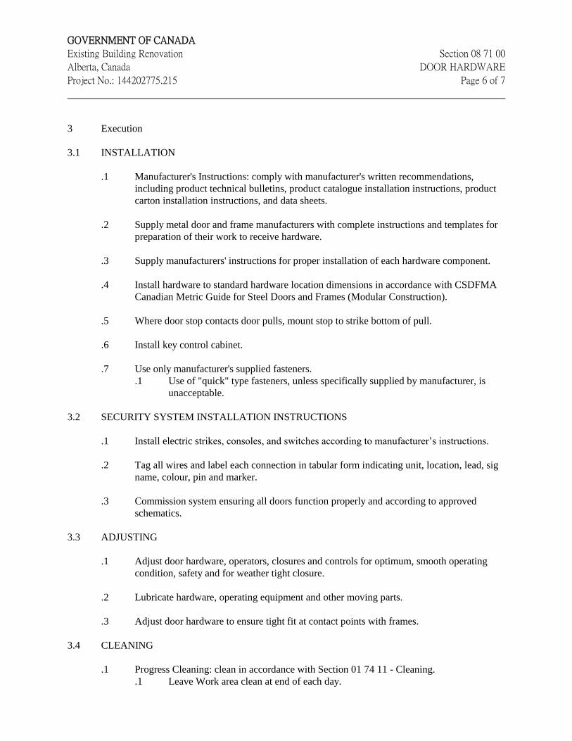
GOVERNMENT OF CANADA
Existing Building Renovation Section 08 71 00
Alberta, Canada DOOR HARDWARE
Project No.: 144202775.215 Page 6 of 7
3 Execution
3.1 INSTALLATION
.1 Manufacturer's Instructions: comply with manufacturer's written recommendations,
including product technical bulletins, product catalogue installation instructions, product
carton installation instructions, and data sheets.
.2 Supply metal door and frame manufacturers with complete instructions and templates for
preparation of their work to receive hardware.
.3 Supply manufacturers' instructions for proper installation of each hardware component.
.4 Install hardware to standard hardware location dimensions in accordance with CSDFMA
Canadian Metric Guide for Steel Doors and Frames (Modular Construction).
.5 Where door stop contacts door pulls, mount stop to strike bottom of pull.
.6 Install key control cabinet.
.7 Use only manufacturer's supplied fasteners.
.1 Use of "quick" type fasteners, unless specifically supplied by manufacturer, is
unacceptable.
3.2 SECURITY SYSTEM INSTALLATION INSTRUCTIONS
.1 Install electric strikes, consoles, and switches according to manufacturer’s instructions.
.2 Tag all wires and label each connection in tabular form indicating unit, location, lead, sig
name, colour, pin and marker.
.3 Commission system ensuring all doors function properly and according to approved
schematics.
3.3 ADJUSTING
.1 Adjust door hardware, operators, closures and controls for optimum, smooth operating
condition, safety and for weather tight closure.
.2 Lubricate hardware, operating equipment and other moving parts.
.3 Adjust door hardware to ensure tight fit at contact points with frames.
3.4 CLEANING
.1 Progress Cleaning: clean in accordance with Section 01 74 11 - Cleaning.
.1 Leave Work area clean at end of each day.
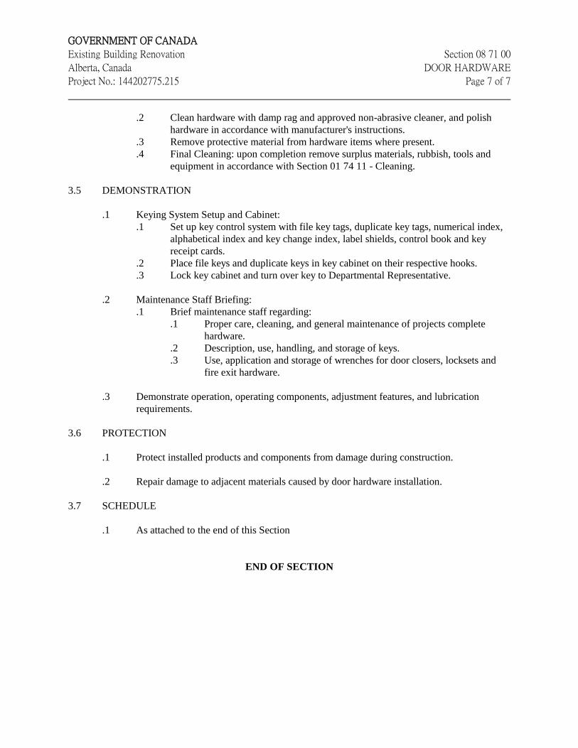
GOVERNMENT OF CANADA
Existing Building Renovation Section 08 71 00
Alberta, Canada DOOR HARDWARE
Project No.: 144202775.215 Page 7 of 7
.2 Clean hardware with damp rag and approved non-abrasive cleaner, and polish
hardware in accordance with manufacturer's instructions.
.3 Remove protective material from hardware items where present.
.4 Final Cleaning: upon completion remove surplus materials, rubbish, tools and
equipment in accordance with Section 01 74 11 - Cleaning.
3.5 DEMONSTRATION
.1 Keying System Setup and Cabinet:
.1 Set up key control system with file key tags, duplicate key tags, numerical index,
alphabetical index and key change index, label shields, control book and key
receipt cards.
.2 Place file keys and duplicate keys in key cabinet on their respective hooks.
.3 Lock key cabinet and turn over key to Departmental Representative.
.2 Maintenance Staff Briefing:
.1 Brief maintenance staff regarding:
.1 Proper care, cleaning, and general maintenance of projects complete
hardware.
.2 Description, use, handling, and storage of keys.
.3 Use, application and storage of wrenches for door closers, locksets and
fire exit hardware.
.3 Demonstrate operation, operating components, adjustment features, and lubrication
requirements.
3.6 PROTECTION
.1 Protect installed products and components from damage during construction.
.2 Repair damage to adjacent materials caused by door hardware installation.
3.7 SCHEDULE
.1 As attached to the end of this Section
END OF SECTION
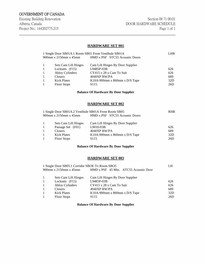
GOVERNMENT OF CANADA
Existing Building Renovation Section 08 71 00.01
Alberta, Canada DOOR HARDWARE SCHEDULE
Project No.: 144202775.215 Page 1 of 1
HARDWARE SET 001
1 Single Door SB01A.1 Room SB01 From Vestibule SB01A LHR
900mm x 2150mm x 45mm HMD x PSF STC55 Acoustic Doors
1 Sets Cam Lift Hinges Cam Lift Hinges By Door Supplier
1 Locksets (F15) L9485P-03B 626
1 Abloy Cylinders CY415 x 28 x Cam To Suit 626
1 Closers 4040XP RW/PA 689
1 Kick Plates K10A-900mm x 860mm x D/S Tape 32D
1 Floor Stops S115 26D
Balance Of Hardware By Door Supplier
HARDWARE SET 002
1 Single Door SB01A.2 Vestibule SB01A From Room SB05 RHR
900mm x 2150mm x 45mm HMD x PSF STC55 Acoustic Doors
1 Sets Cam Lift Hinges Cam Lift Hinges By Door Supplier
1 Passage Set (F01) L9010-03B 626
1 Closers 4040XP RW/PA 689
1 Kick Plates K10A-900mm x 860mm x D/S Tape 32D
1 Floor Stops S115 26D
Balance Of Hardware By Door Supplier
HARDWARE SET 003
1 Single Door SB05.1 Corridor SBOE To Room SBO5 LH
900mm x 2150mm x 45mm HMD x PSF 45 Min. ATC55 Acoustic Door
1 Sets Cam Lift Hinges Cam Lift Hinges By Door Supplier
1 Locksets (F15) L9485P-03B 626
1 Abloy Cylinders CY415 x 28 x Cam To Suit 626
1 Closers 4040XP RW/PA 689
1 Kick Plates K10A-900mm x 860mm x D/S Tape 32D
1 Floor Stops S115 26D
Balance Of Hardware By Door Supplier
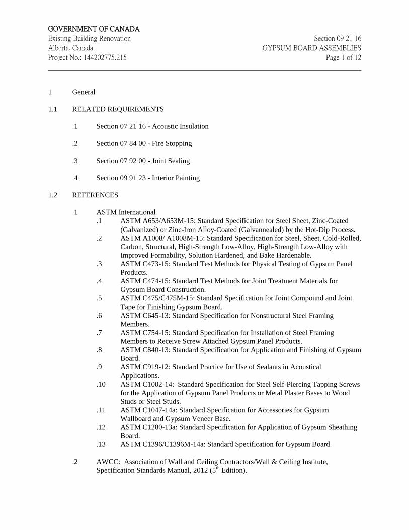
GOVERNMENT OF CANADA
Existing Building Renovation Section 09 21 16
Alberta, Canada GYPSUM BOARD ASSEMBLIES
Project No.: 144202775.215 Page 1 of 12
1 General
1.1 RELATED REQUIREMENTS
.1 Section 07 21 16 - Acoustic Insulation
.2 Section 07 84 00 - Fire Stopping
.3 Section 07 92 00 - Joint Sealing
.4 Section 09 91 23 - Interior Painting
1.2 REFERENCES
.1 ASTM International
.1 ASTM A653/A653M-15: Standard Specification for Steel Sheet, Zinc-Coated
(Galvanized) or Zinc-Iron Alloy-Coated (Galvannealed) by the Hot-Dip Process.
.2 ASTM A1008/ A1008M-15: Standard Specification for Steel, Sheet, Cold-Rolled,
Carbon, Structural, High-Strength Low-Alloy, High-Strength Low-Alloy with
Improved Formability, Solution Hardened, and Bake Hardenable.
.3 ASTM C473-15: Standard Test Methods for Physical Testing of Gypsum Panel
Products.
.4 ASTM C474-15: Standard Test Methods for Joint Treatment Materials for
Gypsum Board Construction.
.5 ASTM C475/C475M-15: Standard Specification for Joint Compound and Joint
Tape for Finishing Gypsum Board.
.6 ASTM C645-13: Standard Specification for Nonstructural Steel Framing
Members.
.7 ASTM C754-15: Standard Specification for Installation of Steel Framing
Members to Receive Screw Attached Gypsum Panel Products.
.8 ASTM C840-13: Standard Specification for Application and Finishing of Gypsum
Board.
.9 ASTM C919-12: Standard Practice for Use of Sealants in Acoustical
Applications.
.10 ASTM C1002-14: Standard Specification for Steel Self-Piercing Tapping Screws
for the Application of Gypsum Panel Products or Metal Plaster Bases to Wood
Studs or Steel Studs.
.11 ASTM C1047-14a: Standard Specification for Accessories for Gypsum
Wallboard and Gypsum Veneer Base.
.12 ASTM C1280-13a: Standard Specification for Application of Gypsum Sheathing
Board.
.13 ASTM C1396/C1396M-14a: Standard Specification for Gypsum Board.
.2 AWCC: Association of Wall and Ceiling Contractors/Wall & Ceiling Institute,
Specification Standards Manual, 2012 (5th Edition).
GOVERNMENT OF CANADA
Existing Building Renovation Section 09 21 16
Alberta, Canada GYPSUM BOARD ASSEMBLIES
Project No.: 144202775.215 Page 2 of 12
.3 Association of the Wall and Ceilings Industries International (AWCI)
.1 AWCI Levels of Gypsum Board Finish.
.4 Underwriters' Laboratories of Canada (ULC)
.1 CAN/ULC-S102-10: Standard Method of Test of Surface Burning Characteristics
of Building Materials and Assemblies.
1.3 ACTION AND INFORMATIONAL SUBMITTALS
.1 Submit in accordance with Section 01 33 00 - Submittal Procedures.
.2 Product Data:
.1 Submit manufacturer's instructions, printed product literature and data sheets for
gypsum board assemblies and include product characteristics, performance
criteria, physical size, finish and limitations.
1.4 DELIVERY, STORAGE AND HANDLING
.1 Deliver, store and handle materials in accordance with Section 01 61 00 - Common
Product Requirements and with manufacturer's written instructions.
.2 Delivery and Acceptance Requirements: deliver materials to site in original factory
packaging, labelled with manufacturer's name and address.
.3 Storage and Handling Requirements:
.1 Store gypsum board assemblies materials level off ground, indoors in dry location
and in accordance with manufacturer's recommendations in clean, dry, well-
ventilated area.
.2 Store and protect gypsum board assemblies from nicks, scratches, and blemishes.
.3 Protect from weather, elements and damage from construction operations.
.4 Handle gypsum boards to prevent damage to edges, ends or surfaces.
.5 Replace defective or damaged materials with new.
.6 Do not load any area of the building beyond the design limits.
1.5 EXAMINATION
.1 Examine drawings, details and schedules. Determine the intent, extent, materials,
location, conditions of interfacing with other work. Be aware of requirements set out
therein.
.2 Inspect surfaces on which the work of this Section is dependent, for unevenness, moisture
and other irregularities detrimental to the application and performance of the work.
Confirm that conditions are satisfactory before proceeding.
.3 Examine and co-ordinate work with other trades and ensure that anchors, blocking,
grounds, electrical conduit, wiring and mechanical work, which is to be installed in or
behind work of this Section, has been installed, tested and accepted.
GOVERNMENT OF CANADA
Existing Building Renovation Section 09 21 16
Alberta, Canada GYPSUM BOARD ASSEMBLIES
Project No.: 144202775.215 Page 3 of 12
.4 Inspect existing conditions which will affect the Work of this Section. Report any
unacceptable conditions to the Departmental Representative. Do not proceed with Work
of this Section until unacceptable conditions have been rectified. Starting Work implies
acceptance of existing conditions.
1.6 PROTECTION
.1 Protect the work against damage by others, from weather or other causes. Protect other
work against damage. Make good any damage caused.
.2 Protect other surfaces from accidental application of taping compound, take particular care
with finished surfaces and glass. Restore damaged work to its original condition.
1.7 AMBIENT CONDITIONS
.1 Maintain temperature 10 degrees C minimum, 21 degrees C maximum for 48 hours prior
to and during application of gypsum boards and joint treatment, and for 48 hours
minimum after completion of joint treatment.
.2 Apply board and joint treatment to dry, frost free surfaces.
.3 Ventilation: ventilate building spaces as required to remove excess moisture that would
prevent drying of joint treatment material immediately after its application.
1.8 FIRE RATED CONSTRUCTION
.1 Erect materials and components to partitions and the like, which are required to have a fire
resistance rating, to meet the Authority Having Jurisdiction listed requirements for the
required rating.
.2 Where a ULC (or other testing laboratory) listing is quoted, ensure that all work and
materials comply with the listed requirements, or are approved by the Authority Having
Jurisdiction.
.3 Erect fire rated partitions to provide the fire separations required. Confirm fire rated
enclosures with mechanical & electrical drawings.
1.9 ACOUSTIC ASSEMBLIES
.1 Maintain continuity of acoustic rated assemblies, including at junction with dissimilar
adjacent materials and components.
GOVERNMENT OF CANADA
Existing Building Renovation Section 09 21 16
Alberta, Canada GYPSUM BOARD ASSEMBLIES
Project No.: 144202775.215 Page 4 of 12
2 Products
2.1 METAL STUDS, FURRING AND SUSPENSION MATERIALS
.1 Metal studs: fabricated from hot dipped or wiped coat galvanized sheet steel conforming
to ASTM C645 and CAN/CGSB-7.1-98. Flanges not less than 32 mm wide, edges bent
back 90 and doubled over to form a 5 mm return. Faces knurled. Knock-out service
holes at 600 mm centres. Widths as noted on the drawings. Use minimum 0.475 mm core
thickness studs. Provide 0.672 mm base metal thickness studs at all door jambs.
.2 Tracks: hot dipped galvanized sheet steel. Width to suit studs. Flanges to be 50 mm.
Track base metal thickness is to match stud thickness as noted above.
.3 Drywall furring channels: hat-shaped, from 0.457 mm core thickness hot-dipped
galvanized sheet steel 22 mm deep x 32 mm wide face.
.4 Other fasteners, clips, splices and the like: suitable for intended application.
2.2 GYPSUM BOARD
.1 Regular Gypsum Board: to ASTM C1396/C1396M, plain, 15.9 mm thick or as indicated,
x 1200 mm wide x maximum permissible length, ends square cut, edges tapered,
paper/paper faced. For gypsum board in acoustically rated partitions, use type X gypsum
board conforming to ASTM C1396/1396M, whether drawings indicate Type X gypsum
board or not.
.2 For use in fire rated construction: to ASTM C1396/C1396M, Type 'X' special ULC
approved fire retardant type, 15.9 mm thickness unless noted otherwise, 1200 mm wide x
maximum permissible length, ends square cut, edges tapered, paper/paper faced. Where
required to meet ULC or Intertek Testing Services (Warnock Hersey) designs, use “C”
formulation fire rated gypsum board, to the satisfaction of the Authority Having
Jurisdiction.
2.3 MISCELLANEOUS MATERIALS
.1 Tape: to ASTM C475, 50 mm wide spark perforated tape; as recommended by the gypsum
board manufacturer.
.2 Jointing compound: to ASTM C475, slow setting, vinyl bedding and finishing compound,
as recommended by gypsum board manufacturer.
.3 Screws: to ASTM C1002, type W for application of gypsum board to wood, Type S for
application of gypsum board to metal framing and type G for application of gypsum board
to gypsum board; Power drilling self-applying type, case hardened, socketed countersunk
head, galvanized, of type and sizes recommended by gypsum board manufacturer and as
required for fire rated partitions.

GOVERNMENT OF CANADA
Existing Building Renovation Section 09 21 16
Alberta, Canada GYPSUM BOARD ASSEMBLIES
Project No.: 144202775.215 Page 5 of 12
.4 Trim: conforming to ASTM C1047; minimum 0.5 mm thickness commercial grade sheet
steel with wiped coat zinc finish to ASTM A924/A924M, type specially design for use in
gypsum board applications, flanges designed to be concealed with taping compound and
as follows:
.1 Casing beads and trim: metal or metal and paper combination "J" type, beaded
angle, with one side perforated for joint filling, to suit gypsum board thickness.
.2 Corner beads: square, metal or metal and paper combination, beaded angle,
flanges 28.6 mm or 32 mm.
.3 Expansion joints: preformed metal, beaded, with one side perforated for joint
filling.
.4 Control Joints: to ASTM C1047, pre-formed galvanized metal or plastic "V"
type, perforated flanges.
.5 Acoustical sealant: To ASTM C919 as specified in Section 07 92 00.
.6 Fasteners: manufacturer's standard suitable for intended application.
.7 Wood and Plywood blocking, framing and backing: as specified in Section 06 10 00 -
Rough Carpentry.
.8 Fire safing filler: rock wool or mineral fibre, conforming to ASTM C612.
.9 Polyethylene Gaskets: 6 mm thick x 89 mm wide, polyethylene foam, "Ethafoam 222" as
manufactured by Dow Chemical Company or Foam Seal R as manufactured by Owens
Corning or preapproved product.
3 Execution
3.1 EXAMINATION
.1 Verification of Conditions: verify conditions of substrates previously installed under other
Sections or Contracts are acceptable for gypsum board assemblies installation in
accordance with manufacturer's written instructions.
.1 Visually inspect substrate in presence of Departmental Representative.
.2 Inform Departmental Representative of unacceptable conditions immediately
upon discovery.
.3 Proceed with installation only after unacceptable conditions have been remedied
and after receipt of written approval to proceed from Departmental
Representative.
3.2 PREPARATION
.1 Do not commence work of this Section until all framing is acceptable to receive gypsum
board.
3.3 ERECTION/METAL STUDS
GOVERNMENT OF CANADA
Existing Building Renovation Section 09 21 16
Alberta, Canada GYPSUM BOARD ASSEMBLIES
Project No.: 144202775.215 Page 6 of 12
.1 Install metal studs and framing in accordance with AWCC Specification Standards
Manual, Section 9.2.
.2 Execute work neatly and accurately, plumb and true, co-ordinated with work of other
trades.
.3 Align walls correctly on accepted lay-out.
.4 Install continuous polyethylene gasket to underside of track to all partitions containing
acoustic batt insulation. Also, install polyethylene gasket where studs abutting existing
and dissimilar construction. Install studs tight against gasket to form a complete acoustic
seal. At corners, intersections and end joints, overlap gasket minimum 75 mm.
.5 Floor and overhead tracks:
.1 For partitions extending to underside of structure, anchor the galvanized sheet
metal channel retaining the top track (for deflection control) to sheet metal
blocking or underside of structure using drilled screw on fasteners at 600 mm o.c.
to concrete structure. Form the upper track 1.6 mm wider to nest with the lower.
Screw studs to the lower track, near the bottom edge of the flange. DO NOT
SCREW STUDS OR TOP CHANNEL THROUGH TO RETAINING
CHANNEL.
.2 Where top track is exposed to permit structural deflection, completely fill void
between double track with 'Fire Safing Insulation'.
.3 Secure floor track in place to concrete slab, at 600 mm o.c. using drilled screw on
fasteners or other accepted fasteners. At exterior walls secure floor track in place
to concrete slab, at 600 mm o.c. using drilled screw in anchors.
.6 Position studs vertically in the tracks, spaced not more than 400 mm o.c., unless indicated
otherwise and not more than 50 mm from abutting walls, and at each side of openings and
corners. Crimp lock studs to tracks except where screw fixing is specified or required,
such as to top track where double top track is indicated. At door frames and other frames,
double up jamb studs. Use minimum 0.762 mm base metal thickness studs at both door
jambs.
.7 Construct corners using minimum three studs.
.8 Provide one continuous row of horizontal bracing in all partitions up to 2.7 m in height,
two rows equally spaced in partitions 2.7 m to 3.6 m in height. Over 3.6 m in height
provide one addition row of bracing for every additional 1.2 m of wall height.
.9 For partitions type with 92 mm wide studs or smaller, with ceiling on one side or no
ceiling on either side of partition, provide diagonal bracing where required. Install so that
underside of bracing is approximately 600 mm above underside of adjacent ceilings. To
all other locations, install horizontal carrying channel brace at 1200 mm maximum o.c. to
interior walls more than 2.4 m high, unless indicated otherwise.
.10 Erect metal studding to tolerance of 1:1000.
GOVERNMENT OF CANADA
Existing Building Renovation Section 09 21 16
Alberta, Canada GYPSUM BOARD ASSEMBLIES
Project No.: 144202775.215 Page 7 of 12
.11 Co-ordinate simultaneous erection of studs with installation of service lines. When
erecting studs ensure web openings are aligned. Install gaskets for all plumbing supports
in steel stud walls.
.12 Jog framing around mechanical ducts or joists as required to maintain fire ratings.
.13 Set door and similar frames into position, align and brace securely until properly anchored.
Anchor bottom of door frames to floors with drilled inserts. Install temporary horizontal
spreader at door mid-height to ensure maintenance of frame width until adjacent work is
completed. After removing bottom (steel) spreader, grind frame smooth.
.14 Erect track at head of door/window openings and sills of sidelight/window openings to
accommodate intermediate studs. Secure track to studs at each end, in accordance with
manufacturer's instructions. Install intermediate studs above and below openings in same
manner and spacing as wall studs.
.15 Frame openings and around built-in equipment, cabinets, access panels, on four sides.
Extend framing into reveals. Check clearances with equipment suppliers.
.16 Install header framing suspended from structure using screws only.
.17 Extend all metal stud partitions to underside of structure except where indicated otherwise.
.18 Allow for structural deflection on all stud walls which terminate at underside of structure,
as follows:
.1 For non-fire rated walls, allow + 25 mm.
.2 For fire rated walls, allow + 15 mm.
.19 At openings, install cut-to-length sections of track with web flanges bent at each end and
securely attached to jamb studs. Where directed, place end infill studs so that it is possible
to have a control joint in line with a door jamb. Frame for all openings larger than 150
mm diameter or side.
.20 Install steel studs or furring channel between studs for attaching electrical and other boxes.
.21 Form control joints in long runs of wall. Place double studs so that control joints will be
no more than 9 m apart. Wherever possible locate control joints at door or window jambs
or as otherwise indicated on the drawings.
.22 Make allowance for packings to furring and the like, as required to provide vertical and
true plane surfaces when furring to and around concrete work.
.23 Where polyethylene gasket is used, ensure that it is compressed for its entire length, to
provide acoustic seal.
3.4 APPLICATION /GYPSUM BOARD
GOVERNMENT OF CANADA
Existing Building Renovation Section 09 21 16
Alberta, Canada GYPSUM BOARD ASSEMBLIES
Project No.: 144202775.215 Page 8 of 12
.1 Generally, apply gypsum board to the requirements of the ASTM C840 and to the AWCC
Specification Standards Manual, Section 9.5 and other referenced standards.
.2 Ensure that blocking, electrical and mechanical work required in or behind gypsum board
has been installed and accepted.
.3 Install gypsum board with face side out.
.4 Apply gypsum board to framing with self-drilling screws of suitable length driven with
power screw driver and set with countersunk head slightly below gypsum board surface.
Screw spacing to ASTM C840 and ASTM C1280 and as noted below. Do not secure
gypsum board to top track where deflection is to be accommodated.
.5 Install screws at a maximum of 200 mm o.c. at periphery of board and at 300 mm o.c. in
field, along each framing member for both single and double application. For fire rated
assemblies, install screws at 175 mm o.c. for partition.
.1 Single-Layer Application:
.1 Apply gypsum board on ceilings prior to application of walls to ASTM
C840.
.2 Apply gypsum board vertically or horizontally, providing sheet lengths
that will minimize end joints.
.2 Double-Layer Application:
.1 Install gypsum board for base layer and exposed gypsum board for face
layer.
.2 Apply base layer to ceilings prior to base layer application on walls; apply
face layers in same sequence. Offset joints between layers at least 250
mm.
.3 Apply base layers at right angles to supports unless otherwise indicated.
.4 Apply base layer on walls and face layers vertically with joints of base
layer over supports and face layer joints offset at least 250 mm with base
layer joints.
.6 For double layer application, use fire rated gypsum board for first layer; screw apply the
second layer of fire rated gypsum board in accordance with fire rating test requirements.
Stagger joints of second layer over underlay.
.7 Apply gypsum tile backer to framing using screws at 150 mm oc along each framing
member.
.8 Install gypsum board to the face of framing around openings where there is no other
finish. Use gypsum board to satisfy all Alberta Building Code 2014 and National
Building Code of Canada 2010 requirements. Install gypsum board to framing around
openings at fire damper locations, to match adjacent gypsum board on walls and to
maintain the required fire ratings and to meet all Alberta Building Code 2014 and
National Building Code of Canada 2010 requirements.
GOVERNMENT OF CANADA
Existing Building Renovation Section 09 21 16
Alberta, Canada GYPSUM BOARD ASSEMBLIES
Project No.: 144202775.215 Page 9 of 12
.9 Fit gypsum board openings snugly to electrical outlets, plumbing piping, and the like, and
make small enough to be covered by plates and escutcheons. Cut both face and back
paper for all cut-outs not made by saw. Seal around all openings using accepted sealant.
In fire rated partitions, ensure that sealant proposed is acceptable to the Authority Having
Jurisdiction. Ensure cut-outs for electrical installations are neatly done using a saw or
knife. Back-cut for clearance to plaster ring. Do not punch holes.
.10 Install control joints in walls and ceilings using back-to-back filled metal beads with 200
mm strip of poly sheet backing, or manufactured control joint with recess for caulking.
Install each member or side of control joint on a separate framing member. Install at 9 m
o.c., at locations acceptable to the Departmental Representative.
.11 Install gypsum board vertically with joints occurring on studs.
.12 Install gypsum board with a minimum 6 mm and maximum 12 mm space between floor
and bottom of gypsum board.
.13 In fire-rated partitions and assemblies, maintain the fire-rating maintained behind
receptacles, switches, panel boxes, and any other penetration of the wall, as required by
the Authority having Jurisdiction and the NBCC 2010.
.14 Verify that all gypsum board is tight to framing prior to application of tape and joint
compound and trim.
.15 Infill, repair, patch and make good existing gypsum board surfaces where damaged or
demolished due to work of this contract. Use gypsum board type and thickness to match
existing gypsum board. Ensure that openings are filled in with gypsum board and that
surfaces are flush with tight joints.
3.5 ACCESSORIES
.1 Erect accessories straight, plumb or level, rigid and at the proper plane. Use full length
pieces where practical. Make joints tight, accurately aligned and rigidly secure. Mitre and
fit corners accurately, free from rough edges. Completely adhere in place in a bed of
jointing compound wherever possible, elsewhere, secure at 800 mm o.c.
.2 Place casing and corner beads straight and rigid. Secure in place in a continuous bed of
jointing compound. For metal corner and casing bead, secure in place at maximum 225
mm o.c. Use longest practical lengths. Place corner beads at all external corners. Place
fill type casing beads where gypsum board abuts a dissimilar material.
.3 Install fill type casing beads where gypsum butts against surfaces having no trim
concealing the junction. Secure beads as for corner beads.
.4 At junctions of partitions and suspended acoustic ceilings, use corner bead in lieu of
casing bead and use dust strips of polyethylene film. Install to achieve a true, even and
level top edge to the gypsum board.
GOVERNMENT OF CANADA
Existing Building Renovation Section 09 21 16
Alberta, Canada GYPSUM BOARD ASSEMBLIES
Project No.: 144202775.215 Page 10 of 12
.5 At junctions between gypsum board ceilings and concrete block walls, install fill type
casing bead tight to walls around edge of ceiling, and fill joint between ceiling and wall
with latex caulking prior to painting.
.6 In non-fire rated partitions and ceiling form control joints using one piece control joint or
back-to-back casing beads with polyethylene dust protector behind joint.
.7 In fire rated partitions and ceilings, install 2 studs at either side of the control joints.
Install 2 layers of 15.9 mm thick fire rated gypsum board to the full length and width of
the stud web at the control joint. Install second stud with 15.9 mm joint between stud face
and face of gypsum board applied to the other stud web as indicated in current edition
Gypsum Association Fire Resistance Design manual. Ensure that control joints are
centred on the edge of the 2 layers of gypsum board applied to the stud web. Fasten
backing and facing panels on one side of joint only. Install one piece control joint at face
of gypsum board, as specified for non-fire rated gypsum board control joints.
.8 Control joints to be at 9 metres o.c. maximum for ceilings and partitions.
.9 At locations where deflection tracks occurs, and the gypsum sheathing or gypsum board
extends up above the deflection tracks, provide a 25 mm wide horizontal control joint in
the gypsum board occurring at the deflection track location, to allow for the deflection in
the studs and gypsum board or gypsum sheathing.
3.6 ACCESS PANELS
.1 Install access panels provided by the mechanical and electrical trades, in positions as
directed by them. Erect plumb and square. Leave clean and operable.
3.7 FINISHING
.1 Mix joint compound in accordance with manufacturer's specifications. Finish joints in
accordance with AWCC Specifications Standards Manual to produce smooth surfaces
ready to receive finishes.
.2 Fill gaps and screw depressions with two coats of joint compound. Allow preceding coat
to set before applying second coat.
.3 On corners apply joint compound to one side of corner and allow to set before applying
compound to the other side of corner.
.4 Apply a thin coat of joint compound over the board on each side of joint and embed the
reinforcing tape and roll firmly in place. Cover edges of tape with a thin coat of joint
compound. Neatly crease tape at internal corners.
.5 To fibreglass faced gypsum board, where fibreglass tape is used, install fibreglass tape into
bedding compound as recommended by the manufacturer.
GOVERNMENT OF CANADA
Existing Building Renovation Section 09 21 16
Alberta, Canada GYPSUM BOARD ASSEMBLIES
Project No.: 144202775.215 Page 11 of 12
.6 Apply joint compound over the flanges of corner and casing beads flush with nose of the
bead and extending at least 75 mm onto the surface of the board.
.7 After bedding coat has set, apply a second coat of joint compound feathered at least 150
mm on each side of butt joint and 100 mm past the flanges of beads.
.8 After the second coat has set apply a third coat of joint compound and feather to 200 mm
on each side of butt joints and 125 mm past the flanges of beads.
.9 Feather coats of joint compound onto adjoining surfaces so that joints, tape holes and
flanges of beads are invisible and so that the camber is 1.6 mm maximum.
.10 After complete treatment has thoroughly set and after at least twenty-four (24) hours, sand
the surface lightly with fine grit sandpaper to leave it smooth and ready for decoration.
.11 Ensure that finish work is seamless, plumb, true, flush and with square, plumb and neat
corners. Sand lightly to remove burred edges and other imperfections. When sanding,
avoid sanding adjacent surface of board and raising nap of paper face.
.12 Completed installation to be smooth, level or plumb, free from waves and other defects
and ready for surface finish.
.13 Tape gypsum board in areas not exposed to view but need not be finished.
.14 Where new gypsum board meets existing gypsum board, tape and fill joints as specified
above, to render joint between new and existing invisible.
.15 Retouch all defects in taping and filling and all other depressions or imperfections in
gypsum board applications after the first prime application under illumination of not less
than 540 lumens/m2.
.16 Gypsum Board Finish: finish gypsum board walls and ceilings to following levels in
accordance with AWCI and AWCC Levels of Gypsum Board Finish:
.1 Levels of finish:
.1 Level 1: embed tape for joints and interior angles in joint compound.
Surfaces to be free of excess joint compound; tool marks and ridges are
acceptable. Use level 1 finish to Where gypsum board is unexposed, such
as above ceilings.
.2 Level 2: embed tape for joints and interior angles in joint compound and
apply one separate coat of joint compound over joints, angles, fastener
heads and accessories; surfaces free of excess joint compound; tool marks
and ridges are acceptable. Use Level 2 finish to gypsum tile backer.
.3 Level 3: embed tape for joints and interior angles in joint compound and
apply two separate coats of joint compound over joints, angles, fastener
heads and accessories; surfaces smooth and free of tool marks and ridges.
Where gypsum board surfaces are to receive special wall coating, finish to
GOVERNMENT OF CANADA
Existing Building Renovation Section 09 21 16
Alberta, Canada GYPSUM BOARD ASSEMBLIES
Project No.: 144202775.215 Page 12 of 12
a level 3 finish, if recommended by the special wall coating manufacturer;
otherwise finish to a Level 4 finish.
.4 Level 4: embed tape for joints and interior angles in joint compound and
apply three separate coats of joint compound over joints, angles, fastener
heads and accessories; surfaces smooth and free of tool marks and ridges.
Use Level 4 where gypsum board surfaces are painted.
3.8 CLEANING
.1 Progress Cleaning: clean in accordance with Section 01 74 11 - Cleaning.
.1 Leave Work area clean at end of each day.
.2 Final Cleaning: upon completion remove surplus materials, rubbish, tools and
equipment in accordance with Section 01 74 11 - Cleaning.
3.9 PROTECTION
.1 Protect installed products and components from damage during construction.
.2 Repair damage to adjacent materials caused by gypsum board assemblies installation.
END OF SECTION
GOVERNMENT OF CANADA
Existing Building Renovation Section 09 51 13
Alberta, Canada ACOUSTIC CEILINGS
Project No.: 144202775.215 Page 1 of 7
1 General
1.1 SUMMARY
.1 Section Includes:
.1 Materials and application of acoustical units for application and installation within
a suspended ceiling.
1.2 RELATED REQUIREMENTS
.1 Section 09 21 16 - Gypsum Board Assemblies
1.3 REFERENCES
.1 ASTM International:
.1 ASTM A641/A641M-09: Specification for Steel Sheet, Zinc-Coated (galvanized)
Carbon Steel Wire.
.2 ASTM C423-09a: Standard Test Method for Sound Absorption and Sound
Absorption Coefficients by the Reverberation Room Method.
.3 ASTM C635/C635M-13a: Standard Specification for the Manufacture,
Performance, and Testing of Metal Suspension Systems for Acoustical Tile and
Lay-in Panel Ceilings.
.4 ASTM C636/C636M-13: Standard Practice for Installation of Metal Ceiling
Suspension Systems for Acoustical Tile and Lay-In Panels.
.5 ASTM E84-15a: Standard Test Method for Surface Burning Characteristics of
Building Materials.
.6 ASTM E119-12a: Standard Test Methods for Fire Test of Building Construction
and Materials.
.7 ASTM E580/E580M-14: Standard Practice for Application of Ceiling Suspension
Systems for Acoustical Tile and Lay-in Panels in Areas Requiring Moderate
Seismic Restraint.
.8 ASTM E795-05(2012): Standard Practice for Mounting Test Specimens During
Sound Absorption Tests.
.9 ASTM E1111-07: Standard Test Method for Measuring Interzone Attenuation of
Ceiling Systems.
.10 ASTM E1264-14: Standard Classification for Acoustical Ceiling Products.
.11 ASTM E1414/E1414M-11a: Standard Test Method for Airborne Sound
Attenuation Between Rooms Sharing a Common Ceiling Plenum.
.12 ASTM E1477-98a(2013): Standard Test Method for Luminous Reflectance
Factor of Acoustical Materials by Use of Integrating-Sphere Reflectometers.
.2 CGSB Standards:
.1 CAN/CGSB-92.1-M89: Sound Absorptive Prefabricated Acoustical Units.
.3 CISCA (AC) - Acoustical Ceilings: Use and Practice; Ceilings & Interior Systems
Construction Association; Current Edition.
GOVERNMENT OF CANADA
Existing Building Renovation Section 09 51 13
Alberta, Canada ACOUSTIC CEILINGS
Project No.: 144202775.215 Page 2 of 7
.4 International Organization for Standardization (ISO):
.1 ISO 4611-2008: Plastic - Determination of the Effects of Exposure to Damp,
Heat, Water Spray and Salt Mist.
.2 ISO 11654-2002: Sound Absorbers for Use in Buildings - Rating of Sound
Absorption.
.3 ISO 14644-1: Classification of Air Cleanliness.
.5 Underwriters' Laboratories of Canada (ULC):
.1 CAN/ULC-S102-10: Surface Burning Characteristics of Building Materials and
Assemblies.
1.4 ACTION AND INFORMATIONAL SUBMITTALS
.1 Submit product data, shop drawings and samples in accordance with Section 01 33 00 -
Submittal Procedures.
.2 Product Data: submit manufacturer’s standard product data for all acoustic ceiling tiles
and suspension systems.
.3 Shop Drawings:
.1 Clearly indicate all system components, types of grid and grid layout, suspension
methods, requirements, and location of mechanical and electrical services and
fixtures, details of components, finish, texture, and all related trim.
.2 Submit proposed methods for attaching hangers to soffits.
.3 Submit duplicate full size samples of each type acoustical units.
1.5 DESIGN
.1 Design acoustical suspension systems for deflection not exceeding 1/360 of span,
considering that lighting fixtures in ceiling area are directly or indirectly supported by the
suspension systems.
.2 Conform to the requirements of ASTM E580.
1.6 QUALITY ASSURANCE
.1 Perform Work of this Section using a well established acoustical ceiling Subcontractor,
employing skilled mechanics. Ensure installer has minimum of five years experience in
performance of product application.
.2 Use a manufacturer specializing in manufacturing of the type of acoustic ceilings specified
in this Section, with a minimum of five (5) years of documented successful experience,
and have the facilities capable of meeting all requirements of Contract Documents as a
single-source responsibility and warranty.
.3 Submit manufacturer's certification that materials meet or exceed specified requirements.

GOVERNMENT OF CANADA
Existing Building Renovation Section 09 51 13
Alberta, Canada ACOUSTIC CEILINGS
Project No.: 144202775.215 Page 3 of 7
.4 Obtain each type of acoustic ceiling tile and T bar grid through one source from a single
manufacturer and from the same production run.
.5 Provide acoustic ceilings that comply with the following requirements:
.1 Surface-Burning Characteristics: provide acoustic panels with surface burning
characteristics complying with CAN/ULC-S102, for class “A” materials as
determined by testing identical products as per CAN/ULC-S102.
.6 Mock-up:
.1 Construct mock-ups in accordance with Section 01 45 00 - Quality Control.
.2 Construct mock-up 10 m2 minimum of each type acoustical tile ceiling including
one inside corner one outside corner.
.3 Construct mock-up where directed.
.4 Allow 72 hours for inspection of mock-up by Departmental Representative before
proceeding with ceiling work.
.5 When accepted, mock-up will demonstrate minimum standard for this work.
Mock-up may remain as part of the finished work.
.7 Health and Safety:
.1 Do construction occupational health and safety in accordance with Section
01 35 29.06 - Health and Safety Requirements.
1.7 DELIVERY, STORAGE AND HANDLING
.1 Protect on site stored or installed absorptive material from moisture damage.
.2 Store extra materials required for maintenance, where directed by Departmental
Representative.
.3 Deliver material to the job site, store and handle in original packages, in an undamaged
condition, with the manufacturer's seals and labels intact.
.4 Do not pile acoustical materials more than 6 cartons high.
.5 Store materials to prevent damage caused by water or breakage, until ready to use.
.6 Damaged materials will be rejected.
1.8 ENVIRONMENTAL REQUIREMENTS
.1 Permit wet work to dry before beginning to install and until mechanical, electrical and all
other systems installed above the ceiling are inspected, tested and accepted.
.2 Maintain uniform minimum temperature of 15 degrees C and humidity of 20% before and
during installation.
.3 Store materials in work area 48 hours prior to installation.
GOVERNMENT OF CANADA
Existing Building Renovation Section 09 51 13
Alberta, Canada ACOUSTIC CEILINGS
Project No.: 144202775.215 Page 4 of 7
1.9 EXTRA MATERIALS
.1 Provide extra materials of acoustic units in accordance with Section 01 78 00 - Closeout
Submittals.
.2 Provide acoustical units amounting to 2% of gross ceiling area for each pattern and type
required for project, from the same production run as the installed tiles.
.3 Ensure extra materials are from same production run as installed materials.
.4 Clearly identify each type of acoustic unit, including colour and texture.
.5 Deliver to Departmental Representative, upon completion of the work of this section.
2 Products
2.1 ACOUSTIC TILE
.1 Acoustic units for suspended ceiling system: to CAN/CGSB-92.1 and ASTM E1264;
sizes, patterns and types as indicated in the Finish Schedule.
.1 Flame spread rating of 25 or less in accordance with CAN/ULC-S102.
.2 Class A fire rating in accordance with CAN/ULC-S102.
.3 Noise Reduction Coefficient (NRC) designation of 0.55.
.4 Ceiling Attenuation Class (CAC) rating 35, in accordance with ASTM E1264
.5 Light Reflectance (LR) range of 0.82 to ASTM E1477.
.6 Edge type: square.
.7 Colour: white.
.8 Size 610 mm x 1220 mm x 16 mm thick.
.9 Shape flat.
2.2 SUSPENSION SYSTEMS
.1 Suspension System: non fire rated standard profile exposed tee bar grid conforming to
ASTM C635, as follows:
.1 Commercial quality cold rolled steel zinc coated, shop painted flat], white. Die
cut interlocking components. Main and cross tee of double web with rectangular
bulb, depth governed by span. Include wall moulding. All components 23.8 mm
exposed face.
2.3 ACCESSORIES
.1 Hangers: pre-stretched galvanized annealed steel wire of adequate gauge for the specified
design conditions.
.2 Fasteners to underside of structure: to concrete structure, use expansion anchor to suit
installation. To wood structure, screw connections with eyebolts.

GOVERNMENT OF CANADA
Existing Building Renovation Section 09 51 13
Alberta, Canada ACOUSTIC CEILINGS
Project No.: 144202775.215 Page 5 of 7
.3 Splices, stabilizer bars: as required to complete and complement the suspended ceiling
grid system.
.4 Edge Trim: 0.556 mm thick zinc coated cold rolled steel with flat white baked enamel
matte finish, 23.8 mm wide on exposed face, regressed edge profile.
.5 Hold down clips: purpose made clips to secure tile to suspension system, approved for use
in fire-rated systems and for use above firing lines.
3 Execution
3.1 EXAMINATION
.1 Do not install acoustical panels and tiles until work above ceiling has been inspected by
Departmental Representative.
3.2 INSTALLATION
.1 Perform Work in strict accordance with material manufacturer's directions to produce an
installation in accordance with the workmanship and performance clauses of the Code of
Practice of 'The National Acoustical Contractors Association' and ASTM C636.
.2 Install ceiling suspension systems to lay-out and heights indicated on reflected ceiling
plans.
.3 Install suspension system level within a tolerance of 1:1000. Finished ceiling system to be
square with adjoining walls.
.4 Install runners supporting ceiling fixtures to remain horizontal across their width within 2
degrees after the fixture loads are imposed.
.5 Attach hangers to underside of the structure using appropriate fasteners to suit existing
conditions and to withstand all superimposed loading. Obtain Departmental
Representative's acceptance of hanger fastenings.
.6 Install hangers at 1.2 m maximum oc and within 150 mm from ends of main tees; securely
attach to the overhead structure. Install additional hangers at each corner of light fixtures
and diffusers. Ensure hangers are well hooked and twisted to prevent loosening under
load. Position wire ends so lifting out does not cause damage to ceiling board.
.7 Install hangers perpendicular to the ceiling both ways. Hangers installed at an angle to the
ceiling will not be accepted.
.8 Co-ordinate the location of hangers with other work. Ensure layout of hangers and
carrying channels are located to accommodate fitting and equipment to be placed after
installation of ceilings.
.9 Hang independently of walls, columns, ducts, pipes and conduit.

GOVERNMENT OF CANADA
Existing Building Renovation Section 09 51 13
Alberta, Canada ACOUSTIC CEILINGS
Project No.: 144202775.215 Page 6 of 7
.10 Install the main tees and cross tees at correct centre to receive the acoustic tile. Install all
acoustic tiles, cut tiles as required.
.11 Install systems in each room or area symmetrical with all other panels of equal dimension,
or as otherwise noted in the reflected ceiling plan.
.12 Install fixtures so that main runners and cross runners are not eccentrically loaded. Where
fixture installation would produce rotation of runner, provide stabilizer bars.
.13 Install regressed edge mouldings at intersection of ceiling and vertical surfaces, using
maximum lengths, straight, true to line and level. Mitre all corners. Provide edge
mouldings at junction with other ceiling finishes.
.14 Under no circumstances suspend the ceiling grid system from any mechanical and
electrical work.
.15 Under no circumstances support or suspend any mechanical work from the ceiling
suspension system.
.16 Immediately reject acoustic board panels which are damaged in any way.
.17 Ensure exposed grids, tiles, and accessories, are free from waves, smears, sags, soiling,
dents, and all other defects.
.18 Do not use "tees" which are chipped, cut, bent out of alignment or damaged in any way
and reject immediately.
.19 Where perimeter supply air diffusers are located, install double tees to accommodate
diffusers.
.20 Install tiles, cut tiles as required. Do not mix lots in the same ceiling area.
.21 Fit acoustic board in place, free from damaged edges or other defects detrimental to
appearance and function.
.22 Install hold-down clips on all lay in tiles to hold such tiles tight to grid system within 3 m
of exterior doors and to ceiling tiles within 2440 mm of firing lines.
.23 Co-operate with the respective trades regarding the installation of ceiling mounted objects.
Cut holes for diffusers, light fixtures, grilles, speakers, smoke detectors, sprinklers, alarms
and the like which are to be installed in the ceiling board. Cut and neatly form and fit
openings in ceilings.
.24 Provide all T bar as required to accommodate mechanical and electrical items such as light
fixtures, diffusers and the like.
GOVERNMENT OF CANADA
Existing Building Renovation Section 09 51 13
Alberta, Canada ACOUSTIC CEILINGS
Project No.: 144202775.215 Page 7 of 7
3.3 CLEANING
.1 Progress Cleaning: clean in accordance with Section 01 74 11 - Cleaning.
.1 Leave Work area clean at end of each day.
.2 Final Cleaning: upon completion remove surplus materials, rubbish, tools and equipment
in accordance with Section 01 74 11 - Cleaning.
.3 Following installation, clean soiled or discoloured surfaces of suspension system and of
acoustical board.
3.4 ADJUSTMENTS
.1 At completion, replace any uneven or defective work, eliminate any waves and sags, and
remedy any damage to exposed surfaces.
END OF SECTION
GOVERNMENT OF CANADA
Existing Building Renovation Section 09 65 16
Alberta, Canada RESILIENT SHEET FLOORING
Project No.: 144202775.215 Page 1 of 9
1 General
1.1 REFERENCES
.1 ASTM International
.1 ASTM F1859-14: Standard Specification for Rubber Sheet Floor Covering
Without Backing.
.2 ASTM F1861-08(2012)e1: Standard Specification for Resilient Wall Base.
.3 ASTM F1869-11: Standard Test Method for Measuring Moisture Vapor Emission
Rate of Concrete Subfloor Using Anhydrous Calcium Chloride.
.4 ASTM F2034-08(2013): Standard Specification for Sheet Linoleum Floor
Covering.
.5 ASTM F3041-14: Bonded Rubber Crumb Floor Coverings.
1.2 ACTION AND INFORMATIONAL SUBMITTALS
.1 Submit in accordance with Section 01 33 00 - Submittal Procedures.
.2 Product Data:
.1 Submit manufacturer's instructions, printed product literature and data sheets for
resilient sheet flooring and include product characteristics, performance criteria,
physical size, finish and limitations.
.3 Samples:
.1 Submit four (4), 300 x 300 mm sample pieces of sheet material, 300 mm long
treads, base, edge strips, nosing.
.4 Submit seaming plan for review.
.5 Maintenance Data: Submit maintenance instructions for insertion in operations and
maintenance manuals include recommended methods and frequency of maintenance for
maintaining optimum condition of work under anticipated usage and use conditions.
Include precautions against using cleaning materials and methods that may be detrimental
to finishes and performance. Include product data for maintenance products recommended
by installer and names, addresses, and telephone numbers of local sources for products.
GOVERNMENT OF CANADA
Existing Building Renovation Section 09 65 16
Alberta, Canada RESILIENT SHEET FLOORING
Project No.: 144202775.215 Page 2 of 9
1.3 QUALIFICATIONS
.1 Installers Qualifications: Trained and approved by the manufacturer and having a
minimum five (5) years experience in the installation of the work described in this Section
and can show evidence of satisfactory completion of projects of similar size, scope and
type with a record of successful in-service performance. If requested, provide letter of
certification from manufacturer stating that installer is certified applicator of its products,
and is familiar with proper procedures and installation requirements required by the
manufacturer.
.1 Qualifications include having the necessary experience, staff, and training to
install manufacturer's products. Manufacturer's willingness to sell its products to
installers does not in itself confer qualification on installer.
.2 Mechanics installing resilient flooring to have a minimum of five (5) years
experience in heat welding installation of linoleum flooring in institutional or
related facilities.
.3 Installers of linoleum to be trained and approved by the linoleum manufacturer
and must be a manufacturer’s master Installer.
.2 Source Limitations: Obtain each type of product from a single manufacturer.
.3 Products: Provide like Products from same production run. Install Products in sequence
from sequentially numbered dye lots.
1.4 MAINTENANCE MATERIAL SUBMITTALS
.1 Extra Materials:
.1 Provide extra materials of resilient sheet flooring and adhesives in accordance
with Section 01 78 00 - Closeout Submittals.
.2 Provide 2% extra of each colour, pattern and type flooring material in full roll
widths, required for project for maintenance use.
.3 Extra materials one piece and from same production run as installed materials.
.4 Identify each roll of sheet flooring and each container of adhesive.
.5 Deliver to Departmental Representative, upon completion of the work of this
section.
.6 Store where directed by Departmental Representative.
1.5 DELIVERY, STORAGE AND HANDLING
.1 Deliver, store and handle materials in accordance with Section with manufacturer's written
instructions and 01 61 00 - Common Product Requirements.
.2 Delivery and Acceptance Requirements: deliver materials to site in original factory
packaging, labelled with manufacturer's name and address.
.3 Storage and Handling Requirements:
.1 Store materials in dry location, indoors, off ground and in accordance with
manufacturer's recommendations in clean, dry, well-ventilated area.
GOVERNMENT OF CANADA
Existing Building Renovation Section 09 65 16
Alberta, Canada RESILIENT SHEET FLOORING
Project No.: 144202775.215 Page 3 of 9
.2 Store and protect specified materials from damage.
.3 Replace defective or damaged materials with new.
1.6 SITE CONDITIONS
.1 Store flooring materials in area of application and allow three days for material to reach
the area air temperature.
.2 Maintain temperatures within range recommended by the manufacturer, but not less than
20C or more than 29C at flooring installation area for three (3) days prior to, during and
for two (2) days after installation. Arrange for controlled ventilation during this period to
avoid high humidity and cold drafts.
.3 After post installation period, maintain temperatures within range recommended by
manufacturer, but not less than 13C or more than 35C.
.4 Install floor coverings after other finishing operations, including painting, have been
completed.
.5 Perform moisture tests on all slabs receiving floor finishes, using the Calcium Chloride
Test procedure in accordance with ASTM F1869. Conduct one test for every 93 m2 of
flooring with test results not exceeding 1.36 kg per 93 m2. If moisture content exceeds
1.36 kg per 93 m2 or as otherwise recommended by the flooring manufacturers at time of
installation of flooring, then apply moisture reduction barrier over slabs prior to
installation of flooring.
.6 Store all linoleum products in the building to acclimatize linoleum as recommended by the
manufacturer prior to installation, under proper and protected ventilation. Ensure that the
building is weather tight and dry with all exterior doors and windows in place.
1.7 PROTECTION
.1 Lay protective covering in traffic areas. Maintain floors in good condition until
completion.
.2 Apply the specified floor finishing as soon as possible after flooring application to protect
the surface.
.3 Prohibit traffic from floor finish for two days after installation.
.4 Protect the walls and work of other Sections before and during the execution of the work
of this Section.
1.8 SITE MEETING
.1 Before commencement of work on site, arrange a site meeting to be attended by the
General Contractor's superintendent, the Subcontractor's representative, the
GOVERNMENT OF CANADA
Existing Building Renovation Section 09 65 16
Alberta, Canada RESILIENT SHEET FLOORING
Project No.: 144202775.215 Page 4 of 9
Subcontractor's foreman for this project, the flooring manufacturer's representative, and
the Departmental Representative.
.2 Specifications and details will be reviewed, including the following:
.1 Scheduling for manufacturer's supervision.
.2 Confirmation of all colours, patterns, samples and miscellaneous materials.
.3 Condition of surfaces.
.4 State of completion of areas.
.5 Protection of finished floor surfaces.
.6 Temperature conditions.
.7 Rolling requirements.
.8 Floor dressing requirements.
1.9 MANUFACTURER SUPERVISION
.1 Make necessary arrangements for initial installation of floor covering materials, to be
supervised by the material manufacturer's representatives.
.2 Obtain Material manufacturer's representative written assurance that installation is carried
out in accordance with manufacturer's specification. Should such specifications conflict
with these specifications, inform the Departmental Representative.
.3 Ensure that the manufacturer's representative makes the inspections together with the
Departmental Representative's Site Representative.
2 Products
2.1 MATERIALS
.1 Linoleum sheet flooring (RES-1): to ASTM F2034, composed of natural ingredients
which are mixed and calendered onto a jute backing:
.1 Type: 1, linoleum sheet with backing.
.2 Backing: jute.
.3 Width: 2 metres.
.4 Pattern: marbleized.
.5 Thickness: 2.5 mm.
.6 Manufacturer, Colour and Type: as indicated in the Finish Schedule.
.2 Rubber sheet flooring (RRF-1): post consumer recycled vulcanized rubber, and coloured
rubber EPDM chips, bonded rubber crumb floor covering conforming to ASTM F3041,
Type 1 & 2, Class A, B, C & D.
.1 Width: 1220 mm.
.2 Length: 15.09 m
.3 Thickness: 9.52 mm (3/8")
.4 Manufacturer, Colour and Type: as indicated in the Finish Schedule.
.3 Resilient base (RCB-1): continuous, top set, complete with premoulded end stops and
external corners:
GOVERNMENT OF CANADA
Existing Building Renovation Section 09 65 16
Alberta, Canada RESILIENT SHEET FLOORING
Project No.: 144202775.215 Page 5 of 9
.1 Type: rubber.
.2 Style: cove.
.3 Thickness: 3.17 mm.
.4 Height: 101.6 mm.
.5 Lengths: cut lengths minimum 2400 mm.
.6 Manufacturer, Colour and Type: as indicated in the Finish Schedule.
.
i) Primers and adhesives: of types recommended by resilient flooring manufacturer for
specific material on applicable substrate, above, on or below grade.
.4 Sub-floor filler and leveller: white premix latex requiring water only to produce
cementitious paste as recommended by flooring manufacturer for use with their product.
.5 Welding Rod: designed to weld seams of sheet flooring, as recommended by flooring
manufacturer, colour to match flooring material.
.6 Metal edge strips:
.1 Aluminum extruded, smooth, polished stainless steel with lip to extend under
floor finish, shoulder flush with top of adjacent floor finish.
.7 Edging to floor penetrations: aluminum, type recommended by flooring manufacturer.
.8 Moisture Reduction Barrier: two component, solvent free, fluid applied breathable epoxy
coating, specially formulated to treat high moisture vapour transmitting concrete surfaces
as determined by a Calcium Chloride Test as per ASTM F1869. Moisture reduction
barrier must be compatible with all flooring adhesives, self levelling compounds and
components applied over it.
.9 Sealer and wax: type recommended by resilient flooring material manufacturer for
material type and location.
3 Execution
3.1 EXAMINATION
.1 Verification of Conditions: verify that conditions of substrate previously installed under
other Sections or Contracts are acceptable for resilient sheet flooring installation in
accordance with manufacturer's written instructions.
.1 Visually inspect substrate in presence of Departmental Representative.
.2 Inform Departmental Representative of unacceptable conditions immediately
upon discovery.
.3 Proceed with installation only after unacceptable conditions have been remedied
and after receipt of written approval to proceed from Departmental
Representative.
.2 Examine surfaces in advance of application. Ensure that floors are protected from
moisture entry.
GOVERNMENT OF CANADA
Existing Building Renovation Section 09 65 16
Alberta, Canada RESILIENT SHEET FLOORING
Project No.: 144202775.215 Page 6 of 9
.3 Check floor surfaces for evidence of carbonation, dusting and excessive moisture. Ensure
Concrete is at least 28 days old, straight, level and firm, free from grease, oil or other
matter detrimental to bond. Do not apply resilient floor to any surface with moisture
content in excess that which is recommended by the flooring manufacturer.
.4 Ensure new floor surfaces are smooth and flat to plus or minus 3 mm over 3 metres.
.5 Do not apply the work of this Section until work which is to receive it and site conditions
are satisfactory.
.6 Notify the Departmental Representative in writing of any defects in such surfaces.
Commencement of work implies acceptance of surfaces and conditions.
.7 When subfloors are ready for installation, request an inspection of the subflooring by the
Departmental Representative and Flooring Manufacturer. Do not proceed with installation
of resilient flooring until sub floors are acceptable to the Departmental Representative and
flooring manufacturer.
3.2 SITE VERIFICATION OF CONDITIONS
.1 Ensure concrete floors are clean and dry by using test methods recommended by flooring
manufacturer.
3.3 PREPARATION
.1 Remove existing resilient flooring, where applicable.
.2 Remove or treat old adhesives to prevent residual, old flooring adhesives from bleeding
through to new flooring and/or interfering with the bonding of new adhesives.
.3 Clean floor and apply filler; trowel and float to leave smooth, flat hard surface. Prohibit
traffic until filler cured and dry.
.4 Remove sub-floor ridges and bumps. Fill low spots, cracks, joints, holes and other defects
with sub-floor filler.
.5 Prime sub-floor to resilient flooring manufacturer's printed instructions.
.6 Before applying flooring adhesive or primer, sweep, clean and vacuum the area involved
thoroughly with industrial vacuum cleaner. Remove all substances deleterious to adhesive
bond.
.7 Feather floors as required using substrate filler, to bring floor covering flush with adjacent
floor surfaces such as porcelain tile, carpet and the like. Ensure that the area feathered is
large enough so that no noticeable slopes or irregularities are created. Extend feathering
out minimum 900 mm, and ramp slope maximum 1 in 30.
GOVERNMENT OF CANADA
Existing Building Renovation Section 09 65 16
Alberta, Canada RESILIENT SHEET FLOORING
Project No.: 144202775.215 Page 7 of 9
3.4 INSTALLATION/MOISTURE REDUCTION BARRIER
.1 If the moisture content of slabs to receive flooring finishes including sports floorings, is
greater than 1.36 kg per 93 m2 at time of flooring installation or less as may be required by
the flooring manufacturers, then apply moisture reduction barrier membrane over all slabs
to receive flooring.
.2 Ensure moisture reduction barrier is compatible with floor finishes and adhesives.
.3 Apply moisture reduction barrier in strict accordance with manufacturer’s
recommendations. Prepare concrete surfaces in strict accordance with manufacturer’s
recommendations.
.4 Apply moisture reduction barrier at rates as recommended by the manufacturer, to suit
existing conditions.
.5 Allow membrane to cure as recommended by the manufacturer, prior to application of self
levelling compounds and finish flooring.
.6 Ensure that the moisture reduction barrier installation is accepted by the Departmental
Representative and the moisture reduction barrier manufacturer’s representative prior to
application of flooring.
3.5 APPLICATION GENERALLY
.1 Install materials according to manufacturer's recommendations using mechanics skilled in
the trade.
.2 Consult other trades in advance and build in or make provisions for installation of their
work to avoid cutting and patching.
.3 Take necessary precautions to minimize noise, odors, dust and inconvenience during
installation.
.4 Spread adhesives, and primers where recommended, evenly over the entire surface
according to manufacturer's directions, using correct type and notching of trowel as
recommended by the flooring and adhesive manufacturer. Do not spread more adhesive
than can be covered before the adhesive hardens. Install materials within time limit
recommended by manufacturer. Remove any overdried adhesive and apply new adhesive.
.5 Cut and fit neatly to frames, breaks, openings, fixtures and around all projections through
flooring. Carry into all closets, toe spaces, recesses, and the like, and under all movable
fitments.
.6 Securely bond entire undersurface of flooring in place. Install flooring continuous through
doorways for similar patterns. Roll flooring with 45.45 kg roller to ensure full bonding to
floor.
GOVERNMENT OF CANADA
Existing Building Renovation Section 09 65 16
Alberta, Canada RESILIENT SHEET FLOORING
Project No.: 144202775.215 Page 8 of 9
.7 Fit corners neatly and accurately scribe around door frames, fitments and such
obstructions.
.8 Distribute variation in shade or pattern of production run to obtain a uniform effect.
Abrupt variations will not be allowed.
.9 Install edge strips to unprotected or exposed edges where floor terminates. Cement edging
strips with contact cement.
.10 Install reducer strips to unprotected or exposed edges where floor terminates against
concrete floor, using one length pieces per locations wherever possible. If joints are
required, use as few joints as possible. Cement reducer strips with contact cement.
.11 Install adapter strips between resilient flooring and carpeting, using one length pieces per
locations wherever possible. If joints are required, use as few joints as possible. Cement
adapter strips with contact cement.
.12 Install adapter strips at doorways with bottom weatherstripping or seals, so that the
weatherstripping or seal does not occur directly over or interfere with adapter strip.
.13 Install reducer strips, adapter strips and edge strips in bed full adhesive, at interface of
dissimilar floorings, where flooring terminates at floors, at flooring exposed edges and
where indicated. Set mouldings with top flush with adjacent floorings. Locate mouldings
below centre of door when door is in closed position, where doors occur.
3.6 APPLICATION: FLOORING
.1 Provide high ventilation rate, with maximum outside air, during installation, and for 48 to
72 hours after installation. If possible, vent directly to outside. Do not let contaminated air
recirculate through district or whole building air distribution system. Maintain extra
ventilation for at least 1 month following building occupation.
.2 Apply adhesive uniformly using recommended trowel. Do not spread more adhesive than
can be covered by flooring before initial set takes place.
.3 Lay flooring with seams parallel to building lines as indicated on the reviewed seaming
plan, to produce a minimum number of seams. Border widths minimum 1/3 width of full
material.
.4 Run sheets in direction of traffic.
.5 Heat weld seams of linoleum sheet flooring in accordance with manufacturer's printed
instructions. Use fully filled welded seams to produce square, straight, flat joints. Install
using the 'double pass' procedure. Install the abutting edges of the covering welded to
form a homogeneous unit, under the action of hot air using a round welding bead.
.6 Install sheet rubber flooring in strict accordance with manufacturer’s recommendations.
GOVERNMENT OF CANADA
Existing Building Renovation Section 09 65 16
Alberta, Canada RESILIENT SHEET FLOORING
Project No.: 144202775.215 Page 9 of 9
.7 Install continuously through doorways for similar patterns. Butt joints under doors if
colours or patterns are dissimilar.
.8 As installation progresses, and after installation roll flooring with 45 kg minimum roller to
ensure full adhesion.
.9 Cut flooring around fixed objects.
.10 Continue flooring over areas which will be under built-in furniture.
.11 Terminate flooring at centreline of door in openings where adjacent floor finish or colour
is dissimilar.
3.7 APPLICATION: BASE
.1 Lay out base to keep number of joints at minimum.
.2 Clean substrate and prime with one coat of adhesive.
.3 Apply adhesive to back of base.
.4 Set base against wall and floor surfaces tightly by using 3 kg hand roller.
.5 Install straight and level to variation of 1:1000.
.6 Scribe and fit to door frames and other obstructions. Use premoulded end pieces at flush
door frames.
.7 Cope internal corners. Use premoulded corner units for right angle external corners. Use
formed straight base material for external corners of other angles.
3.8 CLEANING
.1 Progress Cleaning: clean in accordance with Section 01 74 11 - Cleaning.
.1 Leave Work area clean at end of each day.
.2 Final Cleaning: upon completion remove surplus materials, rubbish, tools and equipment
in accordance with Section 01 74 11 - Cleaning.
.1 Clean flooring and base surfaces to flooring manufacturer's printed instructions.
3.9 PROTECTION
.1 Protect new floors from time of final set of adhesive until final inspection.
.2 Prohibit traffic on floor for 48 hours after installation.
.3 Use only water-based coating for linoleum.

GOVERNMENT OF CANADA
Existing Building Renovation Section 09 65 16
Alberta, Canada RESILIENT SHEET FLOORING
Project No.: 144202775.215 Page 10 of 9
END OF SECTION
GOVERNMENT OF CANADA
Existing Building Renovation Section 09 67 10
Alberta, Canada EPOXY FLOORING
Project No.: 144202775.215 Page 1 of 8
1 General
1.1 REFERENCES
.1 ASTM Standards:
.1 ASTM C413-01(2012): Standard Test Method for Absorption of Chemical-
Resistant Mortars, Grouts, and Monolithic Surfacings and Polymer Concretes.
.2 ASTM C531-00(2012): Standard Test Method for Linear Shrinkage and
Coefficient of Thermal Expansion of Chemical-Resistant Mortars, Grouts,
Monolithic Surfacings, and Polymer Concretes.
.3 ASTM C579-01(2012): Standard Test Methods for Compressive Strength of
Chemical-Resistant Mortars, Grouts, Monolithic Surfacings and Polymer
Concretes.
.4 ASTM D523-14: Standard Test Method for Specular Gloss.
.5 ASTM D580/D580M-10: Standard Specification for Greige Woven Glass Tapes
and Webbings.
.6 ASTM D635-10: Standard Test Method for Rate of Burning and/or Extent and
Time of Burning of Plastics in a Horizontal Position.
.7 ASTM D638-10: Standard Test Method for Tensile Properties of Plastics.
.8 ASTM D695-10: Standard Test Method for Compressive Properties of Rigid
Plastics.
.9 ASTM D790-10: Standard Test Methods for Flexural Properties of Unreinforced
and Reinforced Plastics and Electrical Insulating Materials.
.10 ASTM D1864/D1864M-89(2009)e1: Standard Test Method for Moisture in
Mineral Aggregate Used on Built-Up Roofs.
.11 ASTM D2047-11: Standard Test Method for Static Coefficient of Friction of
Polish-Coated Flooring Surfaces as Measured by the James Machine.
.12 ASTM D2240-05(2010): Standard Test Method for Rubber Property - Durometer
Hardness.
.13 ASTM D4060-10: Standard Test Method for Abrasion Resistance of Organic
Coatings by the Taber Abraser.
.14 ASTM D4226-11: Standard Test Methods for Impact Resistance of Rigid
Poly(Vinyl Chloride) (PVC) Building Products.
.15 ASTM D4258-05(2012): Standard Practice for Surface Cleaning Concrete for
Coating.
.16 ASTM D4259-88(2012): Standard Practice for Abrading Concrete.
.17 ASTM D4260-05(2012): Standard Practice for Acid Etching Concrete.
.18 ASTM D4262-05(2012): Standard Test Method for pH of Chemically Cleaned or
Etched Concrete Surfaces.
.19 ASTM D4263-83(2012): Standard Test Method for Indicating Moisture in
Concrete by Plastic Sheet.
.20 ASTM D4541-09e1: Standard Test Method for Pull-Off Strength of Coatings
Using Portable Adhesion Testers.
.21 ASTM E84-15a: Standard Test Method for Surface Burning Characteristics of
Building Materials.
1.2 ACTION AND INFORMATIONAL SUBMITTALS
GOVERNMENT OF CANADA
Existing Building Renovation Section 09 67 10
Alberta, Canada EPOXY FLOORING
Project No.: 144202775.215 Page 2 of 8
.1 Submit in accordance with Section 01 33 00 - Submittal Procedures.
.2 Product Data:
.1 Submit manufacturer's instructions, printed product literature and data sheets for
epoxy flooring and include product characteristics, performance criteria,
thickness, finish and limitations.
.3 Samples:
.1 Submit four (4), 300 x 300 mm sample of each type of epoxy flooring applied to
Concrete. Submit additional samples until Departmental Representative’s
acceptance is obtained. Make changes in aggregate mix as required to secure
correct colour and texture. Label sample(s) with Project name and number,
applicator, names of material and manufacturer, colour, gloss, texture and
aggregate mix proportion.
.4 Test Reports: certified test reports showing compliance with specified performance
characteristics and physical properties.
.5 Manufacturer's Instructions: submit manufacturer's installation instructions.
1.3 JOB MOCKUP
.1 Construct mockup of epoxy flooring to a 5 m2 area, in a location as directed by the
Departmental Representative. Do not proceed until the mockup has been accepted by the
Departmental Representative.
.2 If accepted, the mockup may be incorporated into the work.
.3 If it is not accepted, remove and re-install another mockup and do not proceed until
mockup has been accepted by the Departmental Representative.
a) CLOSEOUT SUBMITTALS
.1 Submit in accordance with Section 01 78 00 - Closeout Submittals.
.2 Provide specific instructions for maintenance, preservation and cleaning. Provide
adequate warning of maintenance materials or practices which may be detrimental to
flooring.
GOVERNMENT OF CANADA
Existing Building Renovation Section 09 67 10
Alberta, Canada EPOXY FLOORING
Project No.: 144202775.215 Page 3 of 8
1.4 QUALITY ASSURANCE
.1 Installer Qualifications: Trained and approved by the manufacturer and having a minimum
five years experience in the installation of the work described in this Section and can show
evidence of satisfactory completion of projects of similar size, scope and type with a
record of successful in-service performance. If requested, provide letter of certification
from manufacturer stating that installer is certified applicator of its products, and is
familiar with proper procedures and installation requirements required by the
manufacturer.
.1 Qualifications include having the necessary experience, staff, and training to
install manufacturer's products. Manufacturer's willingness to sell its products to
installers does not in itself confer qualification on installer.
.2 Maintenance Seminars: Engage a factory authorized service representative to train
Owner's maintenance personnel on proper maintenance procedures.
.3 Pre-Installation Meeting: Prior to commencing work of this Section, arrange for
manufacturer's technical representative to visit the site and review preparatory and
installation procedures to be followed, conditions under which the work will be done, and
inspect the surfaces to receive the work of this Section. Advise the Departmental
Representative of the date and time of the meeting.
.4 Manufacturer's Site Inspection: Have the manufacturer's technical representative inspect
the Work at suitable intervals during application and at conclusion of the work of this
Section, to ensure the Work is correctly installed. When requested, submit manufacturer's
inspection reports and verification that the work of this Section is correctly installed.
.5 Testing of Concrete Floors: Test floors that have been cured for minimum 28 days, and
after preparation for Product installation is complete and patching or levelling compound
is fully cured. Conduct testing simultaneously on floors free of sealer, curing compounds,
oil, grease and other agents detrimental to the test and Product performance. Locate test
sites to cover representative installation areas. Do not proceed with work when the test
results do not conform to the specified allowable.
.1 Cohesive Strength: Minimum 1.45 MPa by tensile load as tested to CSA
A23.2-6B. Do one test for every 9 sq.m. or fraction thereof.
.2 Moisture Vapour Transmission: ASTM D4263 plastic sheet method, no visible
condensation or vapour allowed. Do one test for every 4.5 sq.m. or fraction
thereof.
.3 Surface Moisture Content: Maximum 4%, tested by moisture meter. Do one test
for every 4.5 sq.m. or fraction thereof.
.4 Surface Temperature: Minimum 3 degree C above the measured dew point.
.6 Apply epoxy flooring in accordance with the most recent installation instructions of the
manufacturer.
1.5 ENVIRONMENTAL REQUIREMENTS

GOVERNMENT OF CANADA
Existing Building Renovation Section 09 67 10
Alberta, Canada EPOXY FLOORING
Project No.: 144202775.215 Page 4 of 8
.1 Maximum moisture content of substrate: 4%.
.2 Temperature: maintain minimum temperature of substrate 12C for a minimum of 48
hours before, during and after installation or until cured unless otherwise required by the
flooring manufacturer. Minimum temperature of air during and for 48 hours after coating
is applied 16C.
.1 Alkali: Ensure negative alkalinity of substrate before application of coating.
.3 Alkali: Ensure negative alkalinity of substrate before application of coating.
.4 Ventilation: provide continuous ventilation during and after coating application to control
dangerous vapour build-up, odours and fumes.
.5 Maintain well lit work area.
.6 Post and enforce "No smoking or open flame" signs until flooring has cured. Eliminate all
spark producing devices (furnaces, all pilot lights, spark-producing switches and the like)
in or near the work area.
.7 Provide uniform and sufficient lighting in areas of installation.
.8 Do not begin flooring installation until all other work which would cause damage, dirt
dust or interruption of normal installation pace has been completed.
1.6 DELIVERY, STORAGE AND HANDLING
.1 Deliver, store and handle materials in accordance with Section 01 61 00 - Common
Product Requirements and with manufacturer's written instructions.
.2 Delivery and Acceptance Requirements: deliver materials to site in original factory
packaging, labelled with manufacturer's name and address.
.3 Storage and Handling Requirements:
.1 Store materials off ground, in dry location and in accordance with manufacturer's
recommendations in clean, dry, well-ventilated area.
.2 Store and protect epoxy flooring materials from damage.
.3 Protect prefinished surfaces with wrapping.
.4 Replace defective or damaged materials with new.
.4 Designate a room for storage of flooring materials and equipment. Keep room neat and
clean at all times, under lock and key, and surrounding surfaces protected from damage.
Keep material temperatures at 16C minimum.
.5 Store flammable materials in safe, approved containers to eliminate fire hazards and
remove from Site at end of each work shift.
.6 Do not use materials that has been stored for period of time exceeding maximum
recommended shelf life of materials
GOVERNMENT OF CANADA
Existing Building Renovation Section 09 67 10
Alberta, Canada EPOXY FLOORING
Project No.: 144202775.215 Page 5 of 8
1.7 PROTECTION
.1 Protect adjacent surfaces from damage resulting from work of this Section. If necessary,
cover or mask adjacent surfaces to those receiving flooring including fixtures and
equipment. Make good any damage so caused, to the satisfaction of the Departmental
Representative.
.2 Replace materials soiled during application, and from which soil cannot be completely
removed, at no extra cost.
.3 Ensure that spark-proof electrical equipment is used in areas where inflammable materials
are being applied. Prevent use of open flames or equipment that may cause sparks.
.4 Keep all traffic out of all areas receiving flooring until it has been completed and cured.
.5 Apply temporary protection until floor is fully cured.
2 Products
2.1 MATERIALS
.1 Epoxy Floor Coating (to flooring SFC-1): Low VOC, low odour, 100% solids; coating
and sealer; slip-resistant finish; manufacturer, colour and type as indicated in on the
Drawings.
.2 Primer: As recommended by manufacturer supplying flooring material for types of
surface to be primed.
.3 Subfloor Filler: Compatible to floor coating and as recommended by coating
manufacturer.
.4 Joint and crack sealant: manufacturer's standard.
.5 Surface conditioner: to manufacturer's standard.
.6 Aggregate: manufacturer's standard as required to achieve a slip resistant finish.
3 Execution
3.1 INSPECTION
.1 Ensure concrete floors conform to manufacturer's requirements.
.2 Ensure that items penetrating coating are placed before application of coating.
.3 Ensure that all surfaces are clean and dry.
GOVERNMENT OF CANADA
Existing Building Renovation Section 09 67 10
Alberta, Canada EPOXY FLOORING
Project No.: 144202775.215 Page 6 of 8
.4 Ensure slabs are properly sloped to drain and that a heavy polyethylene vapour retarder is
installed under the slab.
3.2 PREPARATION OF SURFACES
.1 Protect adjacent surfaces and equipment from damage by overspray, fall-out and dusting.
.2 Ensure surfaces are clean, sound and dry; in all cases requiring some form of preparation.
Prepare substrates in accordance with manufacturer's printed instructions.
.3 Effectively remove concrete laitance by steel shot blasting, grit blasting or method
approved by manufacturer.
.4 Prefill and repair surface irregularities, holes, cracks and other defects in accordance with
manufacturer's recommendations. Level subfloor with filler.
.5 Clean subfloor free of laitance, oil, grease, curing and sealing compounds, hardeners,
chemical additives and other foreign matter detrimental to flooring application.
.6 Prepare concrete floors with shot blasting or other method recommended by manufacturer.
Remove weak concrete, uneven joints, rough areas, foreign and projection off surfaces.
Surface to be hard, and sound. Equip dry blasting machine with vacuum to minimize dust.
.7 Blow clean control joints, sawcuts and cracks with compressed air and grout with material
compatible with floor coating materials.
.8 Ensure that gysum board backing surfaces for cove bases are free of voids and
irregularities.
.9 Before commencement of application of flooring, ensure that concrete floors are
acceptable in accordance with manufacturer's recommendations.
.10 Commencement of work implies acceptance of surfaces and working conditions.
3.3 APPLICATION/EPOXY FLOORING
.1 Ensure that floors have been prepared in accordance with manufacturer's instructions prior
to application of epoxy flooring.
.2 Install cove and base including top cap in accordance with manufacturer's instructions.
Ensure top of base is level, and true to line.
.3 Mix and apply work in strict accordance manufacturer's printed directions in specified
thickness, with integral cove bases, uninterrupted except at sawn joints or other types of
joints required, free of laps, pin holes, voids, crawls, skips or other marks or irregularities
are visible, and to provide uniform appearance.
GOVERNMENT OF CANADA
Existing Building Renovation Section 09 67 10
Alberta, Canada EPOXY FLOORING
Project No.: 144202775.215 Page 7 of 8
.4 Work coating into corners and other restricted areas, up and over bases, and into recesses
in floors to ensure full coverage.
.5 Make clean true junctions with no visible overlap between adjoining applications of
coatings.
.6 Primer: Apply primer over prepared substrate, at manufacturer's recommended spreading
rate with timing of application co-ordinated with subsequent application of topping mix to
ensure optimum adhesion between flooring materials and substrate. Prime entire surface
with recommended primer.
.7 Apply flooring in accordance with manufacturer's instructions to the proper thickness.
.8 Apply grout coats and top coats at recommended coverage, to provide a uniform, dense
surface.
.9 Finish flooring uniformly, free from surface imperfections, and to match the accepted
sample in the Departmental Representative's office.
.10 Allow proper cure time for each installation procedure.
.11 Apply flooring up adjoining walls 150 mm to form base to flooring. Top of base to be
level, true, and even.
.12 Where applicable, flash pipes, conduits and other penetrations to manufacturer's standards.
.13 Incorporate aggregate into topping at rate recommended by the manufacturer to achieve a
slip resistant surface.
.14 Apply sealers over epoxy flooring in strict accordance with manufacturer’s
recommendations.
3.4 CLEANING
.1 Progress Cleaning: clean in accordance with Section 01 74 11 - Cleaning.
.1 Leave Work area clean at end of each day.
.2 Remove protective material from materials where present.
.3 Final Cleaning: upon completion remove surplus materials, rubbish, tools and
equipment in accordance with Section 01 74 11 - Cleaning.
.2 Upon completion of work of this Section clean area up of debris, remove flooring material
from adjacent surfaces where splattered and leave area in clean, tidy condition acceptable
to the Departmental Representative.
.3 Touch up and refinish minor defects in work. Refinish entire coated surface areas where
finish is damaged or otherwise unacceptable.

GOVERNMENT OF CANADA
Existing Building Renovation Section 09 67 10
Alberta, Canada EPOXY FLOORING
Project No.: 144202775.215 Page 8 of 8
.4 Remove promptly as work progresses spilled or splattered coating materials from adjacent
surfaces. Clean floors on completion of Work. Do not mar surfaces while removing
splatters.
.5 Protect completed work from traffic for at least one week to allow proper curing of floor
finish. Protect work from any trades using area after completion of installation.
END OF SECTION
GOVERNMENT OF CANADA
Existing Building Renovation Section 09 91 23
Alberta, Canada INTERIOR PAINTING
Project No.: 144202775.215 Page 1 of 12
1 General
1.1 SUMMARY
.1 Section Includes:
.1 Material and installation of site applied paint finishes to new interior surfaces,
including site painting of shop primed surfaces.
1.2 RELATED REQUIREMENTS
.1 Section 05 50 00 - Metal Fabrications
.2 Section 08 34 73 - Acoustic Doors & Frames
.3 Section 08 56 73 - Sound Control Windows
.4 Section 09 21 16 - Gypsum Board
.5 Section 09 91 23.01 - Interior Re-Painting
1.3 REFERENCES
.1 Department of Justice Canada (Jus)
.1 Canadian Environmental Protection Act (CEPA), 1999, c. 33
.2 Environmental Protection Agency (EPA)
.1 EPA Test Method for Measuring Total Volatile Organic Compound Content of
Consumer Products, Method 24 - 1995, (for Surface Coatings).
.3 Health Canada / Workplace Hazardous Materials Information System (WHMIS)
.1 Material Safety Data Sheets (MSDS).
.4 Master Painters Institute (MPI)
.1 MPI Architectural Painting Specifications Manual, current edition.
.5 National Fire Code of Canada
.6 Society for Protective Coatings (SSPC)
.1 SSPC Painting Manual, Volume Two, 8th Edition, Systems and Specifications
Manual.
.7 Transport Canada (TC)
.1 Transportation of Dangerous Goods Act (TDGA), 1992, c. 34 .

GOVERNMENT OF CANADA
Existing Building Renovation Section 09 91 23
Alberta, Canada INTERIOR PAINTING
Project No.: 144202775.215 Page 2 of 12
1.4 QUALITY ASSURANCE
.1 Qualifications:
.1 Contractor: minimum of five years proven satisfactory experience. Provide list of
last three comparable jobs including, job name and location, specifying authority,
and project manager.
.2 Journeymen: qualified journeymen who have "Tradesman Qualification
Certificate of Proficiency" engaged in painting work.
.3 Apprentices: working under direct supervision of qualified trades person in
accordance with trade regulations.
.2 Pre-Installation Meeting:
.1 Convene pre-installation meeting one week prior to beginning work of this
Section in accordance with Section 01 31 19 - Project Meetings.
.1 Verify project requirements.
.2 Review installation and substrate conditions.
.3 Coordination with other building subtrades.
.4 Review manufacturer's installation instructions and warranty
requirements.
.3 Health and Safety:
.1 Do construction occupational health and safety in accordance with Section
01 35 29.06 - Health and Safety Requirements.
1.5 SCHEDULING
.1 Submit work schedule for various stages of painting to Departmental Representative for
review. Submit schedule minimum of 48 hours in advance of proposed operations.
.2 Obtain written authorization from Departmental Representative for changes in work
schedule.
.3 Schedule painting operations to prevent disruption of occupants.
1.6 ACTION AND INFORMATIONAL SUBMITTALS
.1 Submittals in accordance with Section 01 33 00 - Submittal Procedures.
.2 Product Data:
.1 Submit product data and instructions for each paint and coating product to be
used.
.2 Submit product data for the use and application of paint thinner.
.3 Submit two copies of Workplace Hazardous Materials Information System
(WHMIS) Material Safety Data Sheets (MSDS) in accordance with Section
01 33 00 - Submittal Procedures. Indicate VOCs during application and curing.
GOVERNMENT OF CANADA
Existing Building Renovation Section 09 91 23
Alberta, Canada INTERIOR PAINTING
Project No.: 144202775.215 Page 3 of 12
.3 Samples:
.1 Submit full range colour sample chips to indicate where colour availability is
restricted.
.2 Submit duplicate 200 x 300 mm sample panels of each paint and with specified
paint or coating in colours, gloss/sheen and textures required to MPI Architectural
Painting Specification Manual standards submitted on following substrate
materials:
.1 3 mm for finishes over metal surfaces.
.2 13 mm gypsum board for finishes over gypsum board and other smooth
surfaces.
.3 Retain reviewed samples on-site to demonstrate acceptable standard of quality for
appropriate on-site surface.
.4 Test reports: submit certified test reports for paint from approved independent
testing laboratories, indicating compliance with specifications for specified
performance characteristics and physical properties.
.1 Lead, cadmium and chromium: presence of and amounts.
.2 Mercury: presence of and amounts.
.3 Organochlorines and PCBs: presence of and amounts.
.5 Certificates: submit certificates signed by manufacturer certifying that materials
comply with specified performance characteristics and physical properties.
.6 Manufacturer's Instructions:
.1 Submit manufacturer's application instructions.
.7 Closeout Submittals: submit maintenance data for incorporation into manual
specified in Section 01 78 00 - Closeout Submittals include following:
.1 Product name, type and use.
.2 Manufacturer's product number.
.3 Colour numbers.
.4 MPI Environmentally Friendly classification system rating.
1.7 MAINTENANCE
.1 Extra Materials:
.1 Deliver to extra materials from same production run as products installed. Package
products with protective covering and identify with descriptive labels. Comply
with Section 01 78 00 - Closeout Submittals.
.2 Quantity: provide one - four litre can of each type and colour of finish coating and
stain. Identify colour and paint type in relation to established colour schedule and
finish system.
.3 Delivery, storage and protection: comply with Departmental Representative
requirements for delivery and storage of extra materials.
1.8 DELIVERY, STORAGE AND HANDLING
.1 Packing, Shipping, Handling and Unloading:
.1 Pack, ship, handle and unload materials in accordance with Section 01 61 00 -
Common Product Requirements and manufacturer's written instructions.
GOVERNMENT OF CANADA
Existing Building Renovation Section 09 91 23
Alberta, Canada INTERIOR PAINTING
Project No.: 144202775.215 Page 4 of 12
.2 Acceptance at Site:
.1 Identify products and materials with labels indicating:
.1 Manufacturer's name and address.
.2 Type of paint or coating.
.3 Compliance with applicable standard.
.4 Colour number in accordance with established colour schedule.
.3 Remove damaged, opened and rejected materials from site.
.4 Storage and Protection:
.1 Provide and maintain dry, temperature controlled, secure storage.
.2 Store materials and supplies away from heat generating devices.
.3 Store materials and equipment in well ventilated area with temperature range 7
degrees C to 30 degrees C.
.5 Store temperature sensitive products above minimum temperature as recommended by
manufacturer.
.6 Keep areas used for storage, cleaning and preparation clean and orderly. After completion
of operations, return areas to clean condition.
.7 Remove paint materials from storage only in quantities required for same day use.
.8 Fire Safety Requirements:
.1 Provide one 9 kg Type ABC fire extinguisher adjacent to storage area.
.2 Store oily rags, waste products, empty containers and materials subject to
spontaneous combustion in ULC approved, sealed containers and remove from
site on a daily basis.
.3 Handle, store, use and dispose of flammable and combustible materials in
accordance with National Fire Code of Canada requirements.
1.9 SITE CONDITIONS
.1 Heating, Ventilation and Lighting:
.1 Ventilate enclosed spaces in accordance with Section 01 51 00.
.2 Provide heating facilities to maintain ambient air and substrate temperatures above
10 degrees C for 24 hours before, during and after paint application until paint has
cured sufficiently.
.3 Provide continuous ventilation for seven days after completion of application of
paint.
.4 Coordinate use of existing ventilation system with Departmental Representative
and ensure its operation during and after application of paint as required.
.5 Provide temporary ventilating and heating equipment where permanent facilities
are not available or supplemental ventilating and heating equipment if ventilation
and heating from existing system is inadequate to meet minimum requirements.
.6 Provide minimum lighting level of 323 Lux on surfaces to be painted.
GOVERNMENT OF CANADA
Existing Building Renovation Section 09 91 23
Alberta, Canada INTERIOR PAINTING
Project No.: 144202775.215 Page 5 of 12
.2 Temperature, Humidity and Substrate Moisture Content Levels:
.1 Unless pre-approved written approval by Paint Inspection Agency Authority and
product manufacturer, perform no painting when:
.1 Ambient air and substrate temperatures are below 10 degrees C.
.2 Substrate temperature is above 32 degrees C unless paint is specifically
formulated for application at high temperatures.
.3 Substrate and ambient air temperatures are not expected to fall within
MPI or paint manufacturer's prescribed limits.
.4 The relative humidity is under 85% or when the dew point is more than 3
degrees C variance between the air/surface temperature. Paint should not
be applied if the dew point is less than 3 degrees C below the ambient or
surface temperature. Use sling psychrometer to establish the relative
humidity before beginning paint work.
.5 Rain or snow are forecast to occur before paint has thoroughly cured or
when it is foggy, misty, raining or snowing at site.
.6 Ensure that conditions are within specified limits during drying or curing
process, until newly applied coating can itself withstand 'normal' adverse
environmental factors.
.2 Perform painting work when maximum moisture content of the substrate is below:
.1 12% for plaster and gypsum board.
.3 Test for moisture using calibrated electronic Moisture Meter. Test concrete floors
for moisture using "cover patch test".
.3 Surface and Environmental Conditions:
.1 Apply paint finish in areas where dust is no longer being generated by related
construction operations or when wind or ventilation conditions are such that
airborne particles will not affect quality of finished surface.
.2 Apply paint to adequately prepared surfaces and to surfaces within moisture
limits.
.3 Apply paint when previous coat of paint is dry or adequately cured.
.4 Additional interior application requirements:
.1 Apply paint finishes when temperature at location of installation can be
satisfactorily maintained within manufacturer's recommendations.
.2 Apply paint in occupied facilities during silent hours only. Schedule operations to
approval of Departmental Representative such that painted surfaces will have
dried and cured sufficiently before occupants are affected.
2 Products
2.1 MATERIALS
.1 Paint materials listed in the MPI Approved Products List (APL) are acceptable for use on
this project.
.2 Provide paint materials for paint systems from single manufacturer.

GOVERNMENT OF CANADA
Existing Building Renovation Section 09 91 23
Alberta, Canada INTERIOR PAINTING
Project No.: 144202775.215 Page 6 of 12
.3 Only qualified products with E2 "Environmentally Friendly" rating are acceptable for use
on this project.
.4 Conform to latest MPI requirements for interior painting work including preparation and
priming.
.5 Materials (primers, paints, coatings, varnishes, stains, lacquers, fillers, thinners, solvents,
etc.) in accordance with MPI Architectural Painting Specification Manual "Approved
Product" listing.
.6 Linseed oil, shellac, and turpentine: highest quality product from approved manufacturer
listed in MPI Architectural Painting Specification Manual, compatible with other coating
materials as required.
.7 Provide paint products meeting MPI "Environmentally Friendly" E2 ratings based on
VOC (EPA Method 24) content levels.
.8 Use MPI listed materials having minimum E2 rating where indoor air quality (odour)
requirements exist.
.9 Formulate and manufacture water-borne surface coatings with no aromatic solvents,
formaldehyde, halogenated solvents, mercury, lead, cadmium, hexavalent chromium or
their compounds.
.10 Flash point: 61.0 degrees C or greater for water-borne surface coatings and recycled
water-borne surface coatings.
.11 Ensure manufacture and process of both water-borne surface coatings and recycled water-
borne surface coatings does not release:
.1 Matter in undiluted production plant effluent generating 'Biochemical Oxygen
Demand' (BOD) in excess of 15 mg/L to natural watercourse or sewage treatment
facility lacking secondary treatment.
.2 Total Suspended Solids (TSS) in undiluted production plant effluent in excess of
15 mg/L to natural watercourse or a sewage treatment facility lacking secondary
treatment.
.12 Water-borne paints and stains, recycled water-borne surface coatings and water borne
varnishes to meet minimum "Environmentally Friendly" E2 rating.
2.2 COLOURS
.1 Colours to be as indicated in the Finish Schedule or as otherwise selected by the
Departmental Representative.
.2 Second coat in three coat system to be tinted slightly lighter colour than top coat to show
visible difference between coats.
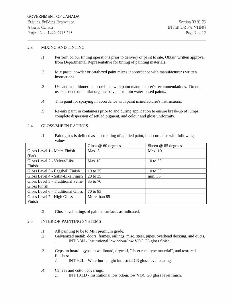
GOVERNMENT OF CANADA
Existing Building Renovation Section 09 91 23
Alberta, Canada INTERIOR PAINTING
Project No.: 144202775.215 Page 7 of 12
2.3 MIXING AND TINTING
.1 Perform colour tinting operations prior to delivery of paint to site. Obtain written approval
from Departmental Representative for tinting of painting materials.
.2 Mix paste, powder or catalyzed paint mixes inaccordance with manufacturer's written
instructions.
.3 Use and add thinner in accordance with paint manufacturer's recommendations. Do not
use kerosene or similar organic solvents to thin water-based paints.
.4 Thin paint for spraying in accordance with paint manufacturer's instructions.
.5 Re-mix paint in containers prior to and during application to ensure break-up of lumps,
complete dispersion of settled pigment, and colour and gloss uniformity.
2.4 GLOSS/SHEEN RATINGS
.1 Paint gloss is defined as sheen rating of applied paint, in accordance with following
values:
Gloss @ 60 degrees Sheen @ 85 degrees
Gloss Level 1 - Matte Finish
(flat)
Max. 5 Max. 10
Gloss Level 2 - Velvet-Like
Finish
Max.10 10 to 35
Gloss Level 3 - Eggshell Finish 10 to 25 10 to 35
Gloss Level 4 - Satin-Like Finish 20 to 35 min. 35
Gloss Level 5 - Traditional Semi-
Gloss Finish
35 to 70
Gloss Level 6 - Traditional Gloss 70 to 85
Gloss Level 7 - High Gloss
Finish
More than 85
.2 Gloss level ratings of painted surfaces as indicated.
2.5 INTERIOR PAINTING SYSTEMS
.1 All painting to be to MPI premium grade.
.2 Galvanized metal: doors, frames, railings, misc. steel, pipes, overhead decking, and ducts.
.1 INT 5.3N - Institutional low odour/low VOC G5 gloss finish.
.3 Gypsum board: gypsum wallboard, drywall, "sheet rock type material", and textured
finishes:
.1 INT 9.2L - Waterborne light industrial G3 gloss level coating.
.4 Canvas and cotton coverings.
.1 INT 10.1D - Institutional low odour/low VOC G3 gloss level finish.
GOVERNMENT OF CANADA
Existing Building Renovation Section 09 91 23
Alberta, Canada INTERIOR PAINTING
Project No.: 144202775.215 Page 8 of 12
2.6 SOURCE QUALITY CONTROL
.1 Perform following tests on each batch of consolidated post-consumer material before
surface coating is reformulated and canned. Testing by laboratory or facility which has
been accredited by Standards Council of Canada.
.1 Lead, cadmium and chromium are to be determined using ICP-AES (Inductively
Coupled Plasma - Atomic Emission Spectroscopy) technique no. 6010 as defined
in EPA SW-846.
.2 Mercury is to be determined by Cold Vapour Atomic Absorption Spectroscopy
using Technique no. 7471 as defined in EPA SW-846.
.3 Organochlorines and PCBs are to be determined by Gas Chromatography using
Technique no. 8081 as defined in EPA SW-846.
3 Execution
3.1 MANUFACTURER'S INSTRUCTIONS
.1 Compliance: comply with manufacturer's written recommendations or specifications,
including product technical bulletins, handling, storage and installation instructions, and
data sheet.
3.2 GENERAL
.1 Perform preparation and operations for interior painting in accordance with MPI
Architectural Painting Specifications Manual except where specified otherwise.
.2 Apply paint materials in accordance with paint manufacturer's written application
instructions.
3.3 EXAMINATION
.1 Investigate existing substrates for problems related to proper and complete preparation of
surfaces to be painted. Report to Departmental Representative damages, defects,
unsatisfactory or unfavourable conditions before proceeding with work.
.2 Conduct moisture testing of surfaces to be painted using properly calibrated electronic
moisture meter, for moisture using simple "cover patch test". Do not proceed with work
until conditions fall within acceptable range as recommended by manufacturer.
.3 Maximum moisture content as follows:
.1 Gypsum board: 12%.
GOVERNMENT OF CANADA
Existing Building Renovation Section 09 91 23
Alberta, Canada INTERIOR PAINTING
Project No.: 144202775.215 Page 9 of 12
3.4 PREPARATION
.1 Protection:
.1 Protect existing building surfaces and adjacent structures from paint spatters,
markings and other damage by suitable non-staining covers or masking. If
damaged, clean and restore surfaces as directed by Departmental Representative.
.2 Protect items that are permanently attached such as Fire Labels on doors and
frames.
.3 Protect factory finished products and equipment.
.4 Protect building occupants in and about the building.
.2 Surface Preparation:
.1 Remove electrical cover plates, light fixtures, surface hardware on doors, bath
accessories and other surface mounted equipment, fittings and fastenings prior to
undertaking painting operations. Identify and store items in secure location and re-
installed after painting is completed.
.2 Move and cover furniture and portable equipment as necessary to carry out
painting operations. Replace as painting operations progress.
.3 Place "WET PAINT" signs in occupied areas as painting operations progress.
Signs to approval of Departmental Representative.
.3 Clean and prepare surfaces in accordance with MPI Architectural Painting Specification
Manual requirements. Refer to MPI Manual in regard to specific requirements and as
follows:
.1 Remove dust, dirt, and other surface debris by vacuuming, wiping with dry, clean
cloths or compressed air.
.2 Wash surfaces with a biodegradable detergent and bleach where applicable and
clean warm water using a stiff bristle brush to remove dirt, oil and other surface
contaminants.
.3 Rinse scrubbed surfaces with clean water until foreign matter is flushed from
surface.
.4 Allow surfaces to drain completely and allow to dry thoroughly.
.5 Prepare surfaces for water-based painting, water-based cleaners should be used in
place of organic solvents.
.6 Use trigger operated spray nozzles for water hoses.
.7 Many water-based paints cannot be removed with water once dried. Minimize use
of mineral spirits or organic solvents to clean up water-based paints.
.4 Prevent contamination of cleaned surfaces by salts, acids, alkalis, other corrosive
chemicals, grease, oil and solvents before prime coat is applied and between applications
of remaining coats. Apply primer, paint, or pretreatment as soon as possible after cleaning
and before deterioration occurs.
.5 Sand and dust between coats as required to provide adequate adhesion for next coat and to
remove defects visible from a distance up to 1000 mm.

GOVERNMENT OF CANADA
Existing Building Renovation Section 09 91 23
Alberta, Canada INTERIOR PAINTING
Project No.: 144202775.215 Page 10 of 12
.6 Clean metal surfaces to be painted by removing rust, loose mill scale, welding slag, dirt,
oil, grease and other foreign substances in accordance with MPI requirements. Remove
traces of blast products from surfaces, pockets and corners to be painted by brushing with
clean brushes, blowing with clean dry compressed air or vacuum cleaning.
.7 Touch up of shop primers with primer as specified.
.8 Do not apply paint until prepared surfaces have been accepted by Departmental
Representative.
3.5 APPLICATION
.1 Method of application to be as approved by Departmental Representative. Apply paint by
brush, roller or airless sprayer. Conform to manufacturer's application instructions unless
specified otherwise.
.2 Brush and Roller Application:
.1 Apply paint in uniform layer using brush and/or roller type suitable for
application.
.2 Work paint into cracks, crevices and corners.
.3 Paint surfaces and corners not accessible to brush using spray, daubers and/or
sheepskins. Paint surfaces and corners not accessible to roller using brush,
daubers or sheepskins.
.4 Brush and/or roll out runs and sags, and over-lap marks. Rolled surfaces free of
roller tracking and heavy stipple.
.5 Remove runs, sags and brush marks from finished work and repaint.
.3 Spray application:
.1 Provide and maintain equipment that is suitable for intended purpose, capable of
atomizing paint to be applied, and equipped with suitable pressure regulators and
gauges.
.2 Keep paint ingredients properly mixed in containers during paint application
either by continuous mechanical agitation or by intermittent agitation as frequently
as necessary.
.3 Apply paint in uniform layer, with overlapping at edges of spray pattern. Back roll
first coat application.
.4 Brush out immediately all runs and sags.
.5 Use brushes and rollers to work paint into cracks, crevices and places which are
not adequately painted by spray.
.4 Use dipping, sheepskins or daubers only when no other method is practical in places of
difficult access.
.5 Apply coats of paint continuous film of uniform thickness. Repaint thin spots or bare
areas before next coat of paint is applied.
GOVERNMENT OF CANADA
Existing Building Renovation Section 09 91 23
Alberta, Canada INTERIOR PAINTING
Project No.: 144202775.215 Page 11 of 12
.6 Allow surfaces to dry and properly cure after cleaning and between subsequent coats for
minimum time period as recommended by manufacturer.
.7 Sand and dust between coats to remove visible defects.
.8 Finish surfaces both above and below sight lines as specified for surrounding surfaces,
including such surfaces as tops of interior cupboards and cabinets and projecting ledges.
.9 Finish inside of cupboards and cabinets as specified for outside surfaces.
.10 Finish closets and alcoves as specified for adjoining rooms.
.11 Finish top, bottom, edges and cutouts of doors after fitting as specified for door surfaces.
3.6 MECHANICAL/ELECTRICAL EQUIPMENT
.1 Paint finished area exposed conduits, piping, hangers, ductwork and other mechanical and
electrical equipment with colour and finish to match adjacent surfaces, except as
indicated.
.2 Boiler room, mechanical and electrical rooms: paint exposed conduits, piping, hangers,
ductwork and other mechanical and electrical equipment.
.3 Other unfinished areas: leave exposed conduits, piping, hangers, ductwork and other
mechanical and electrical equipment in original finish and touch up scratches and marks.
.4 Touch up scratches and marks on factory painted finishes and equipment with paint as
supplied by manufacturer of equipment.
.5 Do not paint over nameplates.
.6 Keep sprinkler heads free of paint.
.7 Paint inside of ductwork where visible behind grilles, registers and diffusers with primer
and one coat of matt black paint.
.8 Paint fire protection piping red.
.9 Paint disconnect switches for fire alarm system and exit light systems in red enamel.
.10 Paint natural gas piping yellow.
.11 Paint both sides and edges of backboards for telephone and electrical equipment before
installation. Leave equipment in original finish except for touch-up as required, and paint
conduits, mounting accessories and other unfinished items.
.12 Do not paint interior transformers and substation equipment.
GOVERNMENT OF CANADA
Existing Building Renovation Section 09 91 23
Alberta, Canada INTERIOR PAINTING
Project No.: 144202775.215 Page 12 of 12
3.7 SITE TOLERANCES
.1 Walls: no defects visible from a distance of 1000 mm at 90 degrees to surface.
.2 Ceilings: no defects visible from floor at 45 degrees to surface when viewed using final
lighting source.
.3 Final coat to exhibit uniformity of colour and uniformity of sheen across full surface area.
3.8 FIELD QUALITY CONTROL
.1 Interior painting and decorating work shall be inspected by a Paint Inspection Agency
(inspector) acceptable to the specifying authority and local Painting Contractor's
Association. Painting contractor shall notify Paint Inspection Agency a minimum of one
week prior to commencement of work and provide a copy of project painting specification,
plans and elevation drawings (including pertinent details) as well as a Finish Schedule.
.2 Interior surfaces requiring painting shall be inspected by Paint Inspection Agency who
shall notify Departmental Representative and General Contractor in writing of defects or
problems, prior to commencing painting work, or after prime coat shows defects in
substrate.
.3 Where "special" painting, coating or decorating system applications (i.e. elastomeric
coatings) or non-MPI listed products or systems are to be used, paint or coating
manufacturer shall provide as part of this work, certification of surfaces and conditions for
specific paint or coating system application as well as on site supervision, inspection and
approval of their paint or coating system application as required at no additional cost to
Departmental Representative.
.4 Standard of Acceptance: meeting tolerances specified in item 3.7 of this Section.
.5 Field inspection of painting operations to be carried out be independent inspection firm as
designated by Departmental Representative.
.6 Advise Departmental Representative when surfaces and applied coating is ready for
inspection. Do not proceed with subsequent coats until previous coat has been approved.
.7 Cooperate with inspection firm and provide access to areas of work.
.8 Retain purchase orders, invoices and other documents to prove conformance with noted
MPI requirements when requested by Departmental Representative.
3.9 RESTORATION
.1 Clean and re-install hardware items removed before undertaken painting operations.
.2 Remove protective coverings and warning signs as soon as practical after operations cease.
GOVERNMENT OF CANADA
Existing Building Renovation Section 09 91 23
Alberta, Canada INTERIOR PAINTING
Project No.: 144202775.215 Page 13 of 12
.3 Remove paint splashings on exposed surfaces that were not painted. Remove smears and
spatter immediately as operations progress, using compatible solvent.
.4 Protect freshly completed surfaces from paint droppings and dust to approval of
Departmental Representative. Avoid scuffing newly applied paint.
.5 Restore areas used for storage, cleaning, mixing and handling of paint to clean condition
as approved by Departmental Representative.
END OF SECTION
GOVERNMENT OF CANADA
Existing Building Renovation Section 09 91 23.01
Alberta, Canada INTERIOR RE-PAINTING
Project No.: 144202775.215 Page 1 of 11
1 General
1.1 RELATED REQUIREMENTS
.1 Section 01 35 16 - Alteration & Renovation Procedures
1.2 REFERENCES
.1 The Master Painters Institute (MPI)
.1 Maintenance Repainting Manual current edition, Master Painters Institute (MPI),
including Identifiers, Evaluation, Systems, Preparation and Approved Product
List.
.2 Environmental Protection Agency (EPA)
.1 Test Method for Measuring Total Volatile Organic Compound Content of
Consumer Products, Method 24 (for Surface Coatings).
.3 Health Canada/Workplace Hazardous Materials Information System (WHMIS)
.1 Material Safety Data Sheets (MSDS).
1.3 QUALITY ASSURANCE
.1 Qualifications:
.1 Contractor: to have a minimum of five years proven satisfactory experience.
Provide a list of last three comparable jobs including, job name and location,
specifying authority, and project manager.
.2 Qualified journeypersons as defined by local jurisdiction to be engaged in
repainting work.
.3 Apprentices: may be employed provided they work under the direct supervision of
qualified journeyperson in accordance with applicable trade regulations.
.2 Conform to latest MPI requirements for interior repainting work including cleaning,
preparation and priming.
.3 Materials (primers, paints, coatings, varnishes, stains, lacquers, fillers, thinners and
solvents) shall be in accordance with the latest edition of the MPI Approved Product List
and shall be from a single manufacturer for each system used.
.4 Paint materials such as linseed oil, shellac, reducers and turpentine shall be the highest
quality product of an approved manufacturer listed in MPI Maintenance Repainting
Manual and shall be compatible with other coating materials as required.
.5 Retain purchase orders, invoices and other documents to prove conformance with noted
MPI requirements when requested by Departmental Representative.
.6 Standard of Acceptance: when viewed using final lighting source surfaces shall indicate
the following:
GOVERNMENT OF CANADA
Existing Building Renovation Section 09 91 23.01
Alberta, Canada INTERIOR RE-PAINTING
Project No.: 144202775.215 Page 2 of 11
.1 Walls: no defects visible from a distance of 1000 mm at 90 degrees to surface.
.2 Ceilings: no defects visible from floor at 45 degrees to surface.
.3 Final coat to exhibit uniformity of colour and sheen across full surface area.
1.4 PERFORMANCE REQUIREMENTS
.1 Environmental Performance Requirements:
.1 Provide paint products meeting MPI "Environmentally Friendly" E2 ratings based
on VOC (EPA Method 24) content levels.
.2 Where indoor air quality (odour) is a problem, use only MPI listed materials
having a minimum E2 rating.
1.5 SCHEDULING
.1 Submit work schedule for various stages of painting to Departmental Representative for
review.
.2 Paint occupied facilities in accordance with approved schedule. Schedule operations to
approval of Departmental Representative such that painted surfaces will have dried and
cured sufficiently before occupants are affected.
.3 Obtain written authorization from Departmental Representative for changes in work
schedule.
.4 Schedule repainting operations to prevent disruption by other trades if applicable and by
occupants in and about building.
1.6 ACTION AND INFORMATIONAL SUBMITTALS
.1 Provide product data and manufacturer's installation/application instructions for each paint
and coating product to be used in accordance with the requirements of Section 01 33 00 -
Submittal Procedures.
.2 Provide samples in accordance with Section 01 33 00 - Submittal Procedures.
.1 Submit full range colour sample chips for review and selection. Indicate where
colour availability is restricted.
.3 Closeout Submittals:
.1 Provide maintenance data for incorporation into manual specified in Section
01 78 00 - Closeout Submittals.
.1 Submit records of products used. List products in relation to finish
system and include following:
.1 Product name, type and use (i.e. materials and location).
.2 Manufacturer's product number.
.3 Colour code numbers.
.4 MPI Environmentally Friendly classification system rating.
.5 Manufacturer's Material Safety Data Sheets (MSDS).
GOVERNMENT OF CANADA
Existing Building Renovation Section 09 91 23.01
Alberta, Canada INTERIOR RE-PAINTING
Project No.: 144202775.215 Page 3 of 11
1.7 DELIVERY, STORAGE AND HANDLING
.1 Deliver, store and handle materials in accordance with Section 01 61 00 - Common
Product Requirements, supplemented as follows:.
.1 Deliver and store materials in original containers, sealed, with labels intact.
.2 Labels to indicate:
.1 Manufacturer's name and address.
.2 Type of paint or coating.
.3 Compliance with applicable standard.
.4 Colour number in accordance with established colour schedule.
.3 Remove damaged, opened and rejected materials from site.
.4 Store and handle in accordance with manufacturer's recommendations.
.5 Store materials and equipment in secure, dry, well-ventilated area with
temperature range between 7 degrees C to 30 degrees C. Store materials and
supplies away from heat generating devices and sensitive products above
minimum temperature as recommended by manufacturer.
.6 Keep areas used for storage, cleaning and preparation, clean and orderly to
approval of Departmental Representative. After completion of operations, return
areas to clean condition to approval of Departmental Representative.
.7 Remove paint materials from storage in quantities required for same day use.
.8 Comply with requirements of Workplace Hazardous Materials Information
System (WHMIS) regarding use, handling storage, and disposal of hazardous
materials.
.9 Fire Safety Requirements:
.1 Provide one 9 kg Type ABC fire extinguisher adjacent to storage area.
.2 Store oily rags, waste products, empty containers and materials subject to
spontaneous combustion in ULC approved, sealed containers and remove
from site daily.
.3 Handle, store, use and dispose of flammable and combustible materials in
accordance with National Fire Code of Canada.
1.8 SITE CONDITIONS
.1 Heating, Ventilation and Lighting:
.1 Do not perform repainting work unless adequate and continuous ventilation and
sufficient heating facilities are in place to maintain ambient air and substrate
temperatures above 10 degrees C for 24 hours before, during and after paint
application and until paint has cured sufficiently.
.2 Ventilate enclosed spaces in accordance with Section 01 51 00. Where required,
provide continuous ventilation for seven days after completion of application of
paint.
.3 Co-ordinate use of existing ventilation system with General Contractor and
Departmental Representative and ensure its operation during and after application
of paint as required.
.4 Provide temporary ventilating and heating equipment where permanent facilities
are not available or supplemental ventilating and heating equipment if ventilation
and heating from existing system is inadequate to meet minimum requirements.
Use of gas-fired appliances is not permitted.
GOVERNMENT OF CANADA
Existing Building Renovation Section 09 91 23.01
Alberta, Canada INTERIOR RE-PAINTING
Project No.: 144202775.215 Page 4 of 11
.5 Do not perform painting work unless minimum lighting level of 323 Lux is
provided on surfaces to be painted.
.2 Temperature, Humidity and Substrate Moisture Content Levels:
.1 Unless specifically pre-approved by specifying body, Paint Inspection Agency
and, applied product manufacturer, do not perform repainting work when:
.1 Ambient air and substrate temperatures are below 10 degrees C.
.2 Substrate temperature is over 32 degrees C unless paint is specifically
formulated for application at high temperatures.
.3 Relative humidity within area to be repainted is above 85%.
.2 Conduct moisture tests using properly calibrated electronic Moisture Meter,
except use simple "cover patch test" on concrete floors to be repainted.
.3 Do not perform repainting work when maximum moisture content of substrate
exceeds:
.1 12% for concrete and masonry (clay and concrete brick/block).
.2 12% for plaster and gypsum board.
.4 Test painted concrete, masonry and plaster surfaces for alkalinity as required.
.3 Surface and Environmental Conditions:
.1 Apply paint finish in areas where dust is no longer being generated by related
construction operations or when ventilation conditions are such that airborne
particles will not affect quality of finished surface.
.2 Apply paint to adequately prepared surfaces and to surfaces within moisture limits
noted herein.
.3 Apply paint when previous coat of paint is dry or adequately cured, unless
otherwise pre-approved by specific coating manufacturer.
.4 Apply paint in occupied facilities in unoccupied rooms or areas. Schedule
operations to approval of the Departmental Representative such that painted
surfaces will have dried and cured sufficiently before occupants are affected.
1.9 MAINTENANCE
.1 Extra Materials:
.1 Submit maintenance materials in accordance with Section 01 78 00 - Closeout
Submittals.
.2 Submit one - four litre can of each type and colour of finish coating. Identify type
and colour in relation to established colour schedule and finish system.
2 Products
2.1 MATERIALS
.1 Paint materials listed in latest edition of MPI Approved Product List (APL) are acceptable
for use on this project.
GOVERNMENT OF CANADA
Existing Building Renovation Section 09 91 23.01
Alberta, Canada INTERIOR RE-PAINTING
Project No.: 144202775.215 Page 5 of 11
.2 Where required by authorities having jurisdiction, paints and coatings to provide a fire
resistant rating.
.3 Paint materials for repaint systems to be products of single manufacturer.
.4 Only qualified products with MPI "Environmentally Friendly" E2 rating are acceptable
for use on this project.
.5 Use only MPI listed L rated materials.
.6 Paints and coatings must not be formulated or manufactured with formaldehyde,
halogenated solvents, mercury, lead, cadmium, hexavalent chromium or their compounds.
2.2 COLOURS
.1 Colours as indicated in the Finish Schedule, or as otherwise selected by the Departmental
Representative.
.2 First coat in two coat (Premium) repaint system to be tinted slightly lighter colour than top
coat to show visible difference between coats.
2.3 MIXING AND TINTING
.1 Perform colour tinting operations prior to delivery of paint to site. On-site tinting of
painting materials is allowed with Departmental Representative's written permission.
.2 Mix paste, powder or catalyzed paint mixes in accordance with manufacturer's written
instructions.
.3 Where thinner is used, addition not to exceed paint manufacturer's recommendations. Do
not use kerosene or such organic solvents to thin water-based paints.
.4 Thin paint for spraying in accordance with paint manufacturer' instructions. If directions
are not on container, obtain instructions in writing from manufacturer and provide copy of
instructions to Departmental Representative.
.5 Re-mix paint in containers prior to and during application to ensure break-up of lumps,
complete dispersion of settled pigment, and colour and gloss uniformity.
2.4 GLOSS/SHEEN RATINGS
.1 Paint gloss defined as sheen rating of applied paint, in accordance with following MPI
gloss / sheen standard values:
Gloss Level Category Units @ 60 Degrees Units @ 85 Degrees
G1 - matte finish 0 to 5 maximum 10
G2 - velvet finish 0 to 10 10 to 35
G3 - eggshell finish 10 to 25 10 to 35
G4 - satin finish 20 to 35 minimum 35
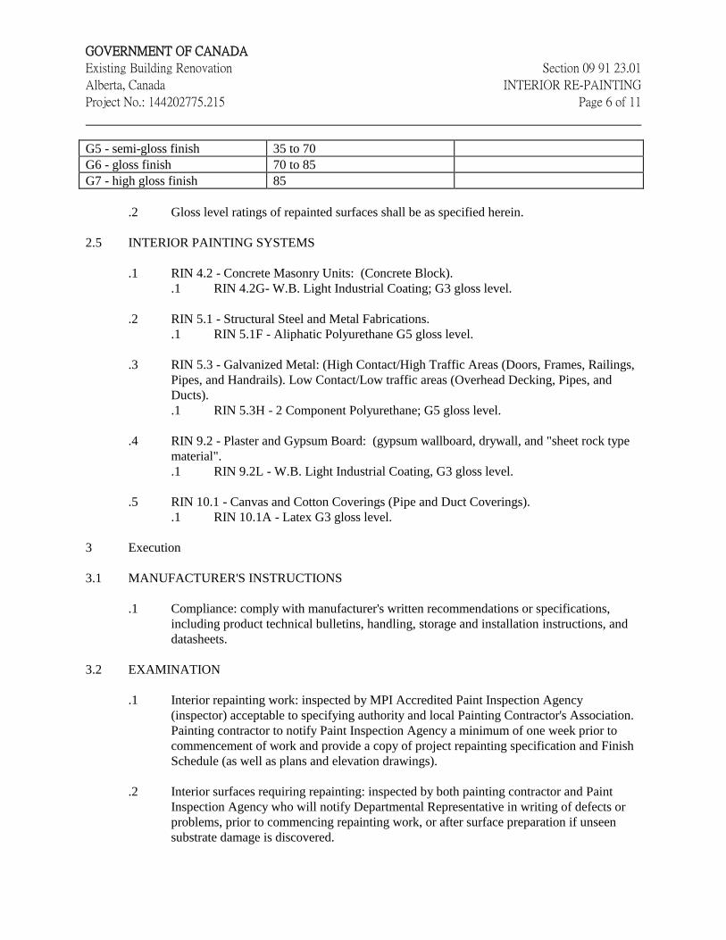
GOVERNMENT OF CANADA
Existing Building Renovation Section 09 91 23.01
Alberta, Canada INTERIOR RE-PAINTING
Project No.: 144202775.215 Page 6 of 11
G5 - semi-gloss finish 35 to 70
G6 - gloss finish 70 to 85
G7 - high gloss finish 85
.2 Gloss level ratings of repainted surfaces shall be as specified herein.
2.5 INTERIOR PAINTING SYSTEMS
.1 RIN 4.2 - Concrete Masonry Units: (Concrete Block).
.1 RIN 4.2G- W.B. Light Industrial Coating; G3 gloss level.
.2 RIN 5.1 - Structural Steel and Metal Fabrications.
.1 RIN 5.1F - Aliphatic Polyurethane G5 gloss level.
.3 RIN 5.3 - Galvanized Metal: (High Contact/High Traffic Areas (Doors, Frames, Railings,
Pipes, and Handrails). Low Contact/Low traffic areas (Overhead Decking, Pipes, and
Ducts).
.1 RIN 5.3H - 2 Component Polyurethane; G5 gloss level.
.4 RIN 9.2 - Plaster and Gypsum Board: (gypsum wallboard, drywall, and "sheet rock type
material".
.1 RIN 9.2L - W.B. Light Industrial Coating, G3 gloss level.
.5 RIN 10.1 - Canvas and Cotton Coverings (Pipe and Duct Coverings).
.1 RIN 10.1A - Latex G3 gloss level.
3 Execution
3.1 MANUFACTURER'S INSTRUCTIONS
.1 Compliance: comply with manufacturer's written recommendations or specifications,
including product technical bulletins, handling, storage and installation instructions, and
datasheets.
3.2 EXAMINATION
.1 Interior repainting work: inspected by MPI Accredited Paint Inspection Agency
(inspector) acceptable to specifying authority and local Painting Contractor's Association.
Painting contractor to notify Paint Inspection Agency a minimum of one week prior to
commencement of work and provide a copy of project repainting specification and Finish
Schedule (as well as plans and elevation drawings).
.2 Interior surfaces requiring repainting: inspected by both painting contractor and Paint
Inspection Agency who will notify Departmental Representative in writing of defects or
problems, prior to commencing repainting work, or after surface preparation if unseen
substrate damage is discovered.
GOVERNMENT OF CANADA
Existing Building Renovation Section 09 91 23.01
Alberta, Canada INTERIOR RE-PAINTING
Project No.: 144202775.215 Page 7 of 11
.3 Where an assessed degree of surface degradation of DSD-1 to DSD-3 before preparation
of surfaces for repainting is revealed to be DSD-4 after preparation, repair or replacement
of such unforeseen defects discovered are to be corrected, as mutually agreed, before
repainting is started.
.4 Where "special" repainting or recoating system applications (i.e. elastomeric coatings) or
non-MPI listed products or systems are to be used, paint or coating manufacturer to
provide as part of work, certification of surfaces and conditions for specific paint or
coating system application as well as on site supervision, inspection and approval of their
paint or coating system application as required at no additional cost to Departmental
Representative.
3.3 PREPARATION
.1 Perform preparation and operations for interior painting in accordance with MPI
Maintenance Repainting Manual requirements except where otherwise specified.
.2 Apply paint materials in accordance with paint manufacturer's written application
instructions.
.3 Clean and prepare interior surfaces to be repainted in accordance with MPI Maintenance
Repainting Manual requirements. Refer to MPI Manual in regard to specific requirements
and as follows:
.1 Remove dust, dirt, and surface debris by vacuuming, wiping with dry, clean cloths
or compressed air.
.2 Wash surfaces with a biodegradable detergent and bleach where applicable and
clean warm water using stiff bristle brush to remove dirt, oil and surface
contaminants.
.3 Rinse scrubbed surfaces with clean water until foreign matter is flushed from
surface.
.4 Allow surfaces to drain completely and to dry thoroughly. Allow sufficient drying
time and test surfaces using an electronic moisture meter before commencing
work.
.5 Use water-based cleaners in place of organic solvents where surfaces will be
repainted using water based paints.
.6 Many water-based paints cannot be removed with water once dried. Minimize use
of kerosene or such organic solvents to clean up water-based paints.
.4 Clean metal surfaces to be repainted by removing rust, dirt, oil, grease and foreign
substances in accordance with MPI requirements. Remove such contaminates from
surfaces, pockets and corners to be repainted by brushing with clean brushes, blowing
with clean dry compressed air, or brushing/vacuum cleaning as required.
.5 Prevent contamination of cleaned surfaces by salts, acids, alkalis, other corrosive
chemicals, grease, oil and solvents before priming and between applications of remaining
coats. Touch-up, spot prime, and apply primer, paint, or pre-treatment as soon as possible
after cleaning and before deterioration occurs.
GOVERNMENT OF CANADA
Existing Building Renovation Section 09 91 23.01
Alberta, Canada INTERIOR RE-PAINTING
Project No.: 144202775.215 Page 8 of 11
.6 Do not apply paint until prepared surfaces have been accepted by Departmental
Representative.
.7 Sand and dust between coats as required to provide adequate adhesion for next coat and to
remove defects visible from distance up to 1000 mm.
3.4 EXISTING CONDITIONS
.1 Prior to commencing work, examine site conditions and existing interior substrates to be
repainted. Report in writing to Departmental Representative and General Contractor
damages, defects, or unsatisfactory or unfavourable conditions or surfaces that will
adversely affect this work.
.2 Conduct moisture testing of surfaces to be painted using properly calibrated electronic
moisture meter, except test concrete floors for moisture using simple "cover patch test"
and report findings to Departmental Representative and General Contractor. Maximum
moisture content not to exceed specified limits.
.3 Do not commence until such adverse conditions and defects have been corrected and
surfaces and conditions are acceptable to Painting Subcontractor and Inspection Agency.
.4 Degree of surface deterioration (DSD) to be assessed using MPI Identifiers and
Assessment criteria indicated in MPI Maintenance Repainting Manual. MPI DSD ratings
and descriptions are as follows:
Condition Description
DSD-0 Sound Surface ( includes visual (aesthetic) defects
that do not affect film's protective properties).
DSD-1 Slightly Deteriorated Surface (indicating fading;
gloss reduction, slight surface contamination, minor
pin holes scratches).
DSD-2 Moderately Deteriorated Surface (small areas of
peeling, flaking, slight cracking, and staining).
DSD-3 Severely Deteriorated Surface (heavy peeling,
flaking, cracking, checking, scratches, scuffs,
abrasion, small holes and gouges).
DSD-4 Substrate Damage (repair or replacement of surface
required).
3.5 PROTECTION
.1 Protect existing surfaces and adjacent fixtures and furnishings from paint spatters,
markings and other damage by suitable non-staining covers or masking. If damaged, clean
and restore such surfaces as directed by Departmental Representative.
.2 Protect items that are permanently attached such as Fire Labels on doors and frames.
.3 Protect factory finished products and equipment.
GOVERNMENT OF CANADA
Existing Building Renovation Section 09 91 23.01
Alberta, Canada INTERIOR RE-PAINTING
Project No.: 144202775.215 Page 9 of 11
.4 Protect general public and building occupants in and about building.
.5 Remove electrical cover plates, light fixtures, surface hardware on doors, bath accessories
and surface mounted equipment, fittings and fastenings prior to undertaking re-painting
operations. Store items and re-install after painting is completed.
.6 Move and cover furniture and portable equipment as necessary to carry out repainting
operations. Replace as painting operations progress.
.7 As repainting operations progress, place "WET PAINT" signs in occupied areas to
approval of Departmental Representative.
3.6 APPLICATION
.1 Apply paint by method that is best suited for substrate being repainted using brush, roller
and/or airless sprayer. Conform to manufacturer's application instructions unless specified
otherwise. Methods of application as pre-approved by Departmental Representative before
commencing work.
.2 Brush and Roller Application:
.1 Apply paint in uniform layer using brush and/or roller of types suitable for
application.
.2 Work paint into cracks, crevices and corners.
.3 Paint surfaces and corners not accessible to brush using spray, daubers and/or
sheepskins. Paint surfaces and corners not accessible to roller using brush,
daubers or sheepskins.
.4 Brush and/or roll out runs and sags, and over-lap marks. Rolled surfaces free of
roller tracking and heavy stipple unless approved by Departmental Representative.
.5 Remove runs, sags and brush marks from finished work and repaint.
.3 Spray Application:
.1 Provide and maintain equipment that is suitable for intended purpose, capable of
properly atomizing paint to be applied, and equipped with suitable pressure
regulators and gauges.
.2 Keep paint ingredients properly mixed in containers during paint application by
continuous mechanical agitation frequently as necessary.
.3 Apply paint in uniform layer, with overlapping at edges of spray pattern.
.4 Back roll spray applications and brush out runs and sags immediately.
.5 Use brushes to work paint into cracks, crevices and places which are not
adequately painted by spray.
.4 Use dipping, sheepskins or daubers when no other method is practical in places of difficult
access and when specifically authorized by Departmental Representative.
.5 Apply paint coats in continuous manner and allow surfaces to dry and properly cure
between coats for minimum time period as recommended by manufacturer. Minimum dry
film thickness of coats not less than that recommended by manufacturer. Repaint thin
spots or bare areas before next coat of paint is applied.
GOVERNMENT OF CANADA
Existing Building Renovation Section 09 91 23.01
Alberta, Canada INTERIOR RE-PAINTING
Project No.: 144202775.215 Page 10 of 11
.6 Sand and dust between coats to remove visible defects.
.7 Repaint surfaces both above and below sight lines as specified for surrounding surfaces,
including such surfaces as tops of interior cupboards and cabinets and projecting ledges.
.8 Repaint top, bottom, and vertical edges of doors to be repainted.
.9 Repaint inside of cupboards and cabinets as specified for outside surfaces.
.10 Repaint closets and alcoves to match existing, unless otherwise scheduled or noted.
3.7 MECHANICAL/ELECTRICAL EQUIPMENT
.1 Unless otherwise noted, repainting to include exposed to view / previously painted
mechanical and electrical equipment and components (panels, conduits, piping, hangers,
and ductwork.).
.2 Touch up scratches and marks and repaint such mechanical and electrical equipment and
components with colour, and sheen finish to match existing unless otherwise noted or
scheduled.
.3 Do not paint over name plates or instruction labels.
.4 Leave unfinished exposed conduits, piping, hangers, ductwork and other mechanical and
electrical equipment in original finish.
.5 Keep sprinkler heads free of paint.
.6 Do not paint interior transformers and substation equipment.
.7 Standard of Acceptance: when viewed using natural prevailing sunlight at peak period of
day (mid-day) on surface viewed, surfaces to indicate following:
.1 Walls: no defects visible from distance of 1000 mm at 90 degrees to surface.
.2 Ceilings: no defects visible from grade at 45 degrees to surface.
.3 Final coat to exhibit uniformity of colour and sheen across full surface area.
3.8 FIELD QUALITY CONTROL
.1 Inspection:
.1 Advise Departmental Representative and Paint Inspection Agency when each
surface and applied coating is ready for inspection. Do not proceed with
subsequent coats until previous coat has been approved.
.2 Co-operate with Paint Inspection Agency and provide access to areas of work.
3.9 CLEANING
.1 Proceed in accordance with Section 01 74 11 - Cleaning, supplemented as follows:
GOVERNMENT OF CANADA
Existing Building Renovation Section 09 91 23.01
Alberta, Canada INTERIOR RE-PAINTING
Project No.: 144202775.215 Page 11 of 11
.1 Remove paint where spilled, splashed, splattered or sprayed as work progresses
using means and materials that are not detrimental to affected surfaces.
.2 Keep work area free from unnecessary accumulation of tools, equipment, surplus
materials and debris.
.3 Remove combustible rubbish materials and empty paint cans each day and safely
dispose of same in accordance with requirements of authorities having
jurisdiction.
.4 Clean equipment and dispose of wash water used for water borne materials,
solvents used for oil based materials as well as other cleaning and protective
materials (e.g. rags, drop cloths, and masking papers), paints, thinners, paint
removers/strippers in accordance with safety requirements of authorities having
jurisdiction and as noted herein.
.5 Clean painting equipment in leak-proof containers that will permit particulate
matter to settle out and be collected. Sediment remaining from cleaning
operations to be recycled or disposed of in manner acceptable to authorities
having jurisdiction.
.6 Recycle paint and coatings in excess of repainting requirements as specified.
3.10 RESTORATION
.1 Clean and re-install hardware items removed before undertaken painting operations.
.2 Remove protective coverings and warning signs as soon as practical after operations cease.
.3 Remove paint splashings on affected exposed surfaces. Remove smears and spatter
immediately as operations progress, using compatible solvent.
.4 Protect freshly completed surfaces from paint droppings and dust to approval of
Departmental Representative. Avoid scuffing newly applied paint.
.5 Restore areas used for storage, cleaning, mixing and handling of paint to clean condition
as approved by Departmental Representative.
END OF SECTION

GOVERNMENT OF CANADA
Existing Building Renovation Section 11 67 23
Alberta, Canada SHOOTING RANGE EQUIPMENT
Project No.: 144202775.215 Page 1 of 6
1 General
1.1 RELATED REQUIREMENTS
.1 Section 02 41 16 - Selective Demolition.
1.2 DESCRIPTION OF WORK
.1 Perform installation under the direct supervision of the shooting range equipment
manufacturer.
.2 All equipment specified under this section shall be provided by (1) manufacturer to insure
compatibility and product performance capability.
1.3 QUALITY ASSURANCE
.1 Shooting range equipment manufacturers must meet the following qualifications: A firm
having ten (10) years experience in fabrication and installation of work of the quality and
scope required on this project.
.2 Upon request provide a list of five (5) representative completed law enforcement type
shooting range equipment installations in continuous use for three (3) years, with name,
address and phone number of the Departmental Representative and a brief description for
each project.
.3 The shooting range equipment supplier must have ISO 9001:2008 Quality Management
System and an ISO 14001:2004 Environmental Management System. Information
confirming such shall be provided upon request.
1.4 ACTION AND INFORMATIONAL SUBMITTALS
.1 Submit in accordance with Section 01 33 00 - Submittal Procedures.
.2 Product Data:
.1 Submit manufacturer's instructions, printed product literature and data sheets for
all shooting range equipment and include product characteristics, performance
criteria, physical size, finish and limitations.
.3 Shop Drawings:
.1 Submit shop drawings, indicating all equipment, sizes, materials, fabrication,
installation, fastening, mechanical and electrical data and connection details.
Coordinate all details on shop drawings with exact locations for mechanical and
electrical work.
.4 Test Reports: certified test reports showing compliance with specified performance
characteristics and physical properties.
.5 Manufacturer's Instructions: submit manufacturer's installation instructions.
GOVERNMENT OF CANADA
Existing Building Renovation Section 11 67 23
Alberta, Canada SHOOTING RANGE EQUIPMENT
Project No.: 144202775.215 Page 2 of 6
1.5 CLOSEOUT SUBMITTALS
.1 Submit in accordance with Section 01 78 00 - Closeout Submittals.
.2 Operation and Maintenance Data: submit operation and maintenance data for shooting
range equipment for incorporation into manual.
1.6 DELIVERY, STORAGE AND HANDLING
.1 Deliver, store and handle materials in accordance with Section 01 61 00 - Common
Product Requirements and with manufacturer's written instructions.
.2 Delivery and Acceptance Requirements: deliver materials to site in original factory
packaging, labelled with manufacturer's name and address.
.3 Storage and Handling Requirements:
.1 Store materials off ground, in dry location and in accordance with manufacturer's
recommendations in clean, dry, well-ventilated and secure area. Do not use non-
vented plastic or canvas shelters that could create a humidity chamber.
.2 Store and protect shooting range equipment from damage.
.3 Protect prefinished surfaces with wrapping.
.4 Replace defective or damaged materials with new.
.4 Inspect equipment upon delivery for damage.
2 Products
2.1 GRANULAR BALLISTICS TRAPS
.1 Granulate: specialty treated rubber granulate made from recycled materials, to safely stop
bullets and maintain their basic original shape, thus minimizing broken up lead particles
released into the atmosphere.
.2 Provide system for all small arms including handguns, shotguns, and rifles with a
maximum velocity of 3600 FPS and maximum energy of 3600 ft. lbs.
.3 Size: foot print to be no less than 3760 mm. Overall height to be as indicated on the
drawings and reviewed shop drawings.
GOVERNMENT OF CANADA
Existing Building Renovation Section 11 67 23
Alberta, Canada SHOOTING RANGE EQUIPMENT
Project No.: 144202775.215 Page 3 of 6
.4 Provide granular ballistics trap with a sloping front surface constructed with a stepped
steel bedplate, box tube support frame and must incorporate an upper hopper bin, filled
with replenishment rubber material. This upper bin consists of an angled 10 mm AR500
@ 470-500 BHN armor plate slope sheet. Provide lower trap section, bedplates, to
support rubber granules. These rubber granules consist of chopped rubber and shall be
predominately free of cording, threads, steel belting pieces and cotton fibers. Fired rounds
will be captured by the rubber granulate with little or no fragmentation or back-splatter.
The steel bedplate provides a safety barrier. The design of the trap shall be such that
under normal service and maintenance, the 3.57 mm thick steel bedplate shall not be relied
upon to terminate the bullets flight.
.5 The granular ballistics trap's steel bedplates must be in a deep stepped configuration and
not a simple angled plate. The primary impact area's step depth (Measured at the
Horizontal steel bed plate) shall not be less than 610 mm. This required stepped design
allows for greater rubber granule and lead retention in the granular ballistics trap's primary
impact areas.
.6 The granular ballistics traps must incorporate an internal, separately enclosed & conveyor
belt faced - backup Safety Bin - with additional rubber granulate within. This back-up area
shall be no less than 250 mm in depth.
.7 The granular ballistics trap shall allow the recovery of largely intact spent rounds.
.8 The granular ballistics trap shall be self-supporting and assembled entirely by mechanical
fasteners. The upper holding bins must be part of the Granular ballistics traps frame
support assembly and not require overhead support via chains/cables, bridging or rear wall
attachment and the like. The traps upper frame shall support the Granular ballistics traps
10 mm thick - AR500 Armor plate upper slope sheet and must extend no less than 1500
mm from the rear side of the trap assembly. No on-the-job cutting or welding shall be
required.
.9 All metal parts not otherwise finished or plated shall be primed and painted.
.10 Note that use of this deeper granular ballistics trap design will require relocation of the
existing 25 metre target line. Anticipate the new target line at 3048 mm from the rear
edge of the new granular ballistics trap. Range Equipment Provider is to retain as much
target distance as possible - without being detrimental to the equipments operational and
service needs.
.11 Granular trap to meet the following requirements:
.1 Stepped bed plates. In addition to the primary loose rubber material depth - the
traps primary impact area must hold an additional volume of 8 cubic feet.
.2 10 mm thick AR500 plate facing on the traps upper replenishment bin.
.3 The replenishment bin - when full and level with traps top elevation - must hold a
volume of 19 cubic feet of rubber granulate material.
GOVERNMENT OF CANADA
Existing Building Renovation Section 11 67 23
Alberta, Canada SHOOTING RANGE EQUIPMENT
Project No.: 144202775.215 Page 4 of 6
.4 Granular ballistics traps upper replenishment bin must be a solid boxed steel
frame that is fastened to the traps main support frames - and not suspended via
chain or cables. The entire trap must be self supporting with no required
attachment to the rear wall or ceiling structure.
.5 Granular ballistics trap must incorporate a "back-up" safety bin at the traps rear
side. This area is to hold 10 cubic feet of rubber granulate.
.6 Granular ballistics traps support frames must be of tube / boxed steel. Use of
angle iron, lumber or other support in not acceptable.
2.2 PROTECTIVE CEILING PANELS
.1 The ceiling system is a combination of specially designed protection panels. These panels
are made to fit the range precisely and to maximize the protection. From the Firing Line -
a series of combined horizontal and angled panels will be installedThe safety ceiling (SC)
and panels are created by mounting a 12.7 mm Fire Rated Treated plywood panel to a Fire
rated treated 38 mm x 89 mm wood frame to a 10 mm thick - AR500 steel Armor Plate
panel.
.2 The re-directive guards are fabricated from 10 mm thick - AR500 Armor plate steel have a
bare steel frontal surface.
.3 Provide all Suspension hardware (chains, cables, "S"-hooks & turnbuckles) as required.
.4 Light Cove deflectors shall have a 10 mm thick AR500 frontal surface (Bare steel) and
arrive pre-punched with anchor holes and related mounting hardware. Panels to have a
factory applied coat of primer on all sides.
.5 The Ceiling panel's bottom surfaces are to have an open cell foam/acoustical material
attached, to reduce the sound level in the range. Provide and install a sufficient quantity
of 50 mm acoustical foam/sound deadening material by the range equipment
manufacturer, to cover the facing of the safety ceiling . This acoustical foam material shall
be based on the Anechoic-Wedge Principle. The acoustical foam shall be Class 1 rated.
(Flammability - ASTM E 84 Class 1, Flame Spread - 5, Smoke Density - 90.
.6 Range equipment provider to also provide & install 25 mm x 610 mm x 610 mm Shredded
Rubber Planks (SRP) on the underside of the existing range ceiling. Installation of 38 mm
x 89 mm furring strips on 400 mm centers - up & down the length of the range - as well as
a layer of 19 mm plywood. FIRE RATED TREATED LUMBER TO BE UTILIZED.
Furring and plywood locations shall be indicated on the range equipment providers shop
drawings.
.7 Provide and install any bridging (if required) for any obstructions that interfere with the
ceiling panel installation.
2.3 COMBAT WALLS
.1 Combat Wall System: consists of 10 mm thick - AR500 Armor backing plate, wood

GOVERNMENT OF CANADA
Existing Building Renovation Section 11 67 23
Alberta, Canada SHOOTING RANGE EQUIPMENT
Project No.: 144202775.215 Page 5 of 6
framed air space chamber, 12.7 mm plywood and a 25 mm rubber facing. FIRE RATED/
TREATED LUMBER MUST BE USED. The steel panels arrive prefabricated & ready
for installation.
.2 Coverage to include the bullet trap sidewalls and continue continuously back to the 25
Meter primary firing line - at an elevation of 2440 mm.
.3 The system shall be modular in design to facilitate ease of installation. The entire system
shall include all framing and assembly fasteners. The panels shall be firmly secured to the
wall via mastic and mechanical fasteners.
2.4 PROTECTIVE CEILING PANELS
.1 The ceiling system is a combination of specially designed protection panels. These panels
are made to fit the range precisely and to maximize the protection. From the Firing Line -
a series of combined horizontal and angled panels will be installed. The safety ceiling
(SC) and are created by mounting a 12.7 mm fire rated treated plywood panel to a fire
rated treated 38 mm x 89 mm wood frame to a 10 mm thick - AR500 steel Armor Plate
panel.
.2 The re-directive guards are fabricated from 10 mm thick - AR500 Armor plate steel have a
bare steel frontal surface.
.3 Provide all Suspension hardware (chains, cables, "S"-hooks & turnbuckles) as required.
.4 Light cove deflectors shall have a 10 mm thick AR500 frontal surface (Bare steel) and
arrive pre-punched with anchor holes and related mounting hardware. Panels to have a
factory applied coat of primer on all sides.
.5 The ceiling panel's bottom surfaces are to have an open cell foam/acoustical material
attached, to reduce the sound level in the range. Provide and install a sufficient quantity
of 50 mm acoustical foam/sound deadening material by the range equipment
manufacturer, to cover the facing of the safety ceiling . This acoustical foam material shall
be based on the Anechoic-Wedge Principle. The acoustical foam shall be Class 1 rated.
(Flammability - ASTM E 84 Class 1, Flame Spread - 5, Smoke Density - 90).
.6 Provide and install any bridging (if required) for any obstructions that interfere with the
ceiling panel installation.
2.5 GUN CLEARING TRAP
.1 Provide Gun Clearing Trap for a safe and secure means of clearing guns during loading
and unloading. Gun clearing traps shall protect both the shooter and bystanders from an
accidental discharge by safely containing the bullet.
.1 Provide (1) Rifle Rated Gun Clearing Trap; Weapon-Clear as manufactured by
MilPolice Equipment, www.MilPolice.com.
.2 The clearing trap shall be a self-standing/floor model that does not require a stand
or special mounting hardware to secure it.
GOVERNMENT OF CANADA
Existing Building Renovation Section 11 67 23
Alberta, Canada SHOOTING RANGE EQUIPMENT
Project No.: 144202775.215 Page 6 of 6
.3 The clearing trap shall accommodate pistole and rifle rounds up to 0.50 BMG AP
and meet Wiltshire Balistic Services: 48 rounds in total from 300 ft/lbs to 13334
ft/lbs.
.4 The clearing trap shall utilize safety signage that illustrates its capabilities and
limitations.
3 Execution
3.1 RANGE CLEANING/DEMOLITION WORK
.1 Perform all demolition work in accordance with Section 02 41 16 - Selective Demolition.
3.2 INSTALLATION
.1 The work must be completed in accordance with standard practice in equipment
manufacture and in a manner acceptable to the Departmental Representative.
.2 Install in exact accordance with manufacturer's instructions and submittals.
.3 Provide installation by the equipment manufacturer.
.4 Provide all wiring of control systems under the direct supervision of the equipment
manufacturer.
.5 Install all components in a rigid secure manner.
.6 Adjust target system for proper operation.
.7 At installation completion, provide the services of a representative of the firearms training
equipment to demonstrate proper operation and maintenance training of the complete
system in accordance with Section 01 79 00 - Demonstration and Training.
.8 Manufacturer must provide a toll-free telephone number and a dedicated toll-free customer
service number with access to a customer service representative. Provide follow up
courtesy services/training visit from a factory trained service technician, for the target
retrieval systems, within one year of installation.
3.3 CLEANING
.1 Progress Cleaning: clean in accordance with Section 01 74 11 - Cleaning.
.1 Leave Work area clean at end of each day.
.2 Remove protective material from materials where present.
.3 Final Cleaning: upon completion remove surplus materials, rubbish, tools and
equipment in accordance with Section 01 74 11 - Cleaning.
END OF SECTION
GOVERNMENT OF CANADA Existing Building Renovation Section 21 05 00
Alberta, Canada COMMON WORK RESULTS FOR
Project No.: 144202775.215 FIRE SUPPRESSION
Page 1 of 2
1. General
1.1 Intent
.1 Work in Division 21, will include all drawings and all sections of the specifications that
form the Contract Documents, including all addenda, and including Division 00 and
Division 01, whether defined in Division 21 or elsewhere, or whether defined in
mechanical drawings or elsewhere.
.2 Provide complete, fully tested and operational mechanical systems to meet requirements
described herein and in complete accord with applicable codes and ordinances. Include
all costs to obtain all permits and to pay for all fees and charges, including inspection
charges by the authorities that issue the permits. Coordinate all related inspections.
Permits, fees and inspections including:
.1 Sprinklers
.2 Fire Protection
.3 Third party engineering fees
.3 Contract documents consisting of the specifications and drawings, are generally
diagrammatic and approximately to scale unless detailed otherwise. They establish
scope, material and installation quality and are not detailed installation instructions.
.4 Review Contract Documents and notify the Consultant of issues or conflict that require
clarification prior to submitting tender. Failure by the Contractor to secure clarification
does not relieve the Contractor to comply with the intent of the design and/or the
Contract Document.
1.2 Related Requirements
.1 Refer to and comply with the following sections:
.1 General Requirements Division 01
.2 Submittal Procedures Section 01 33 00
.3 Delegated Design Submittals Section 01 33 50
.4 Quality Control Section 01 45 00
.5 Temporary Facilities and Controls Section 01 51 00
.6 Execution Requirements Section 01 73 00
.7 Closeout Procedures Section 01 77 00
.8 Closeout Submittals Section 01 78 00
.9 Demonstration and Training Section 01 79 00
.10 Commissioning Section 01 91 00
GOVERNMENT OF CANADA Existing Building Renovation Section 21 05 00
Alberta, Canada COMMON WORK RESULTS FOR
Project No.: 144202775.215 FIRE SUPPRESSION
Page 2 of 2
.11 Building Management Manual (BMM) Section 01 91 51
1.3 Related Work Specified In Other Sections
.1 For complete Common Work requirements refer to Section 23 05 00 – Common Work
Results for HVAC.
2. Products
.2 For complete Common Work requirements refer to Section 23 05 00 – Common Work
Results for HVAC.
3. Execution
.3 For complete Common Work requirements refer to Section 23 05 00 – Common Work
Results for HVAC.
END OF SECTION
GOVERNMENT OF CANADA Existing Building Renovation Section 21 05 23
Alberta, Canada GENERAL DUTY VALVES FOR WATER
Project No.: 144202775.215 BASED FIRE SUPPRESSION PIPING
Page 1 of 2
1. General
1.1 Scope
.1 Gate valves
.2 Butterfly valves
.3 Check valves
1.2 Reference Documents
.1 American Society for Testing and Materials (ASTM):
.1 ASTM A126-04 Standard Specification for Gray Iron
Castings for Valves, Flanges, and Pipe
Fittings
.2 ASTM B21/B21M-06 Standard Specification for Naval Brass
Rod, Bar, and Shapes
.3 ASTM B61-08 Standard Specification for Steam or
Valve Bronze Castings
.4 ASTM B62-09 Standard Specification for Composition
Bronze or Ounce Metal Castings
.5 ASTM B98/B98M-08 Standard Specification for Copper-
Silicon Alloy Rod, Bar and Shapes
.6 ASTM B139/B139M-07 Standard Specification for Phosphor
Bronze Rod, Bar, and Shapes
.2 National Fire Protection Association (NFPA):
.1 NFPA 13-2013 Standard for the Installation of Sprinkler
Systems
.2 NFPA 14-2010 Standard for the Installation of
Standpipe Systems
.3 Manufacturers Standardization Society Standard Practices (Current Editions)
.1 SP-67 Butterfly Valves
.2 SP-70 Gray Iron Gate Valves, Flanged and
Threaded Ends
GOVERNMENT OF CANADA Existing Building Renovation Section 21 05 23
Alberta, Canada GENERAL DUTY VALVES FOR WATER
Project No.: 144202775.215 BASED FIRE SUPPRESSION PIPING
Page 2 of 2
.3 SP-71 Gray Iron Swing Check Valves, Flanged
and Threaded Ends
.4 SP-80 Bronze Gate, Globe, Angle, and Check
Valves
.5 SP-82 Valve Pressure Testing Methods
1.3 Manufacturer
.1 Provide valves of the same type by the same manufacturer throughout.
.2 Valves shall bear the following information permanently marked on the valve body”
.1 Manufacturer’s name or trademark
.2 Pressure rating
.3 Flow direction
.3 Valves for fire protection service to be ULC Listed and FM Approved.
1.4 Shop Drawings
.1 Submit detailed shop drawings clearly indicating make, model, size, pressure rating,
materials of construction and intended service.
2. Products
.1 For complete General Duty Valve requirements refer to Section 22 05 23 – General Duty
Valves for Plumbing Piping.
3. Execution
.1 For complete General Duty Valve requirements refer to Section 22 05 23 – General Duty
Valves for Plumbing Piping.
END OF SECTION
GOVERNMENT OF CANADA Existing Building Renovation Section 21 05 29
Alberta, Canada HANGERS AND SUPPORTS FOR
Project No.: 144202775.215 FIRE SUPPRESSION PIPING AND EQUIPMENT
Page 1 of 2
1. General
1.1 Scope
.1 Pipe hangers and supports
.2 Sleeving for mechanical equipment
.3 Equipment bases and supports
.4 Pipe anchors
.5 Access Doors
1.2 Reference Standards
.1 Pipe supports shall meet the requirements of ANSI B31.1 Power Piping.
.2 Automatic sprinkler pipe supports shall meet the requirements of NFPA No.13, Standard
for the Installation of Sprinkler Systems.
1.3 General Requirements
.1 Provide hangers and supports to secure equipment in place, prevent vibration, maintain
grade, and provide for expansion and contraction.
.2 Install supports of strength and rigidity to suit loading without unduly stressing the
building. Locate adjacent to equipment to prevent undue stresses in piping and
equipment. Where support is from concrete construction, avoid weakening concrete or
penetrating waterproofing.
.3 Select hangers and supports for the service and in accordance with manufacturer's
recommended maximum loading. Hangers shall have a safety factor of 5 to 1.
.4 Fasten supports and hangers to building structure. Use inserts for suspending hangers
from reinforced concrete slabs and sides of reinforced concrete beams wherever practical.
When possible, set inserts in position in advance of concrete work. Drill concrete where
inserts must be placed after concrete is poured.
.5 Where structural bearings do not exist or where inserts are not in suitable locations for
proper installation of pipes, conduits and ducts, provide approved support made of steel
channels or angles from which to suspend hangers. Do not use existing piping, crane
rails, trolley beams, mono rails, etc, for support.
.6 No percussion type fastening of any kind will be permitted without prior approval.
.7 Provide and set sleeves or block-outs required for equipment, including openings
required for placing equipment.
GOVERNMENT OF CANADA Existing Building Renovation Section 21 05 29
Alberta, Canada HANGERS AND SUPPORTS FOR
Project No.: 144202775.215 FIRE SUPPRESSION PIPING AND EQUIPMENT
Page 2 of 2
.8 Provide sleeves for all piping through rated assemblies. In non-rated assemblies, provide
sleeves for all domestic hot, domestic cold, and domestic recirculation piping. Sleeves to
be sized to allow insulation to pass through and to project through both sides of wall.
.9 Provide sleeves for all piping through ceilings, floors and footings.
.10 Do not weld piping or equipment supports to building metal decking or building
structural steel supports unless prior written approval has been obtained from the
structural engineer.
.11 Obtain approval prior to drilling for inserts and supports for piping system. Discuss and
obtain approval for hanging systems and methods with Structural Engineer.
.12 Obtain approval prior to using percussion type fastenings.
.13 Use of piping or equipment for hanger supports and use of perforated band iron, wire or
chain as hangers is not permitted.
1.4 Submittals
.1 Submit shop drawings for access doors.
2. Products
.1 For complete hanger, support and access door requirements for fire suppression refer to
Section 23 05 29 – Hangers and Supports for HVAC Piping and Equipment.
3. Execution
.1 For complete hanger, support and access door requirements for fire suppression refer to
Section 23 05 29 – Hangers and Supports for HVAC Piping and Equipment.
END OF SECTION
GOVERNMENT OF CANADA Existing Building Renovation Section 21 05 53
Alberta, Canada IDENTIFICATION FOR FIRE SUPPRESSION
Project No.: 144202775.215 PIPING AND EQUIPMENT
Page 1 of 2
1. General
1.1 Scope
.1 Painting and identification of equipment, piping and related components for the
following:
.1 Fire Protection Systems
1.2 Related Work Specified in Other Sections
.1 General Requirements Division 01
.2 Interior Painting Section 09 91 23
.3 Common Work Results for HVAC Section 23 05 00
.4 Identification for HVAC Piping and Equipment Section 23 05 53
1.3 Reference Standards
.1 Canadian General Standards Board (CGSB)
.1 CGSB-1-GP-12c; Color Identification and Selection
.2 CAN/CGSB-24.3 – Identification of Piping Systems
.2 National Fire Protection Association (NFPA)
.1 NFPA 13-2010, Standard for the Installation of Sprinkler Systems
.2 NFPA 14-2010, Standard for the Installation of Standpipe and Hose Systems
.3 American Society of Mechanical Engineers (ASME)
.1 ASME A13.1-2007, Scheme for the Identification of Piping Systems
.4 Federal Standard 595C – Colors
.5 WHMIS Pictograms – Workplace Hazardous Materials Information System – GHS
Globally Harmonized System of Classification and Labeling Chemicals) – Pictograms
1.4 Quality Control
.1 Coordinate color coding of piping and equipment with work of Section 09 91 23 –
Interior Painting.
.2 All painting identified in this section is to be performed by Section 09 91 23 – Interior
Painting Contractor, under the direction of the Division 21 contractor.

GOVERNMENT OF CANADA Existing Building Renovation Section 21 05 53
Alberta, Canada IDENTIFICATION FOR FIRE SUPPRESSION
Project No.: 144202775.215 PIPING AND EQUIPMENT
Page 2 of 2
.3 Color code mechanical equipment and piping. Refer to Part 3 of this section.
.4 Submit a schedule of pipe and equipment identification methods, materials and colors to
the Engineer for review.
1.5 Definitions
.1 For the purposes of this Section, the following definitions apply:
.1 Concealed: Piping and equipment in trenches, shafts, furrings and suspended
ceilings.
.2 Exposed: Piping and equipment in mechanical rooms or otherwise not
“concealed”.
1.6 Equipment Protection and Clean-Up
.1 Ensure that new and existing equipment and surfaces are carefully covered with tarping,
or heavy duty plastic. Ensure that spills and splatter on finishes and equipment are
cleaned up totally and promptly.
2. Products
Not Applicable
3. Execution
.1 For complete identification requirements refer to Section 23 05 53 – Identification for
HVAC Piping and Equipment.
END OF SECTION
GOVERNMENT OF CANADA Existing Building Renovation Section 21 13 13
Alberta, Canada WET PIPE SPRINKLER SYSTEMS
Project No.: 144202775.215 Page 1 of 7
1. General
1.1 Scope
.1 Equipment, piping, including sprinkler heads, valves, hangers and supports, sleeves, fire
department connections, and accessories.
.2 Contractor shall be responsible for coordination of all fire alarm interlocks with Division
26.
1.2 General Requirements
.1 Provide complete sprinkler system as required by local codes and as indicated on
drawings. Size of sprinkler system based on light hazard occupancy and ordinary hazard
occupancy group 1.
.2 Provide sprinklers for areas as indicated and as required, including specialized rooms.
Run piping concealed above furred ceilings and in joist to minimize obstructions. Expose
only heads.
.3 Hydraulically size sprinkler system based on the actual water supply data which must be
obtained from municipal utility.
1.3 Quality Assurance
.1 All municipal bylaws, provincial statutes and NFPA Standards governing the installation
shall be strictly adhered to.
.2 Provide all labor and materials in accordance with the requirements of the fire marshal
having jurisdiction. Comply fully with the rules and regulations stated in current
National Building Code and the following NFPA Standards, those editions which are in
effect locally and in the Province of Alberta.
.3 Guarantee that the quantities of sprinklers proposed meet the requirements of this
specification. If the quantities are not within these requirements, provide additional
sprinklers and their installation at no additional cost to the contract.
.4 Sprinkler equipment and installation shall be in accordance with the current standards and
approved local Fire Commissioner.
.5 Equipment and installation shall meet the requirements of current edition of NFPA 13 -
Standard for the Installation of Sprinkler Systems.
.6 Sprinkler equipment shall be installed by qualified contractors licensed and regularly
engaged in installation of automatic fire sprinkler equipment.
.7 Refer to Section 21 05 00 – Common Work Results for Fire Suppression for welding
requirements
GOVERNMENT OF CANADA Existing Building Renovation Section 21 13 13
Alberta, Canada WET PIPE SPRINKLER SYSTEMS
Project No.: 144202775.215 Page 2 of 7
1.4 Reference Standards
.1 National Fire Protection Association (NFPA)
.1 NFPA 13 2013 Standard for the Installation of Sprinkler
Systems
.2 National Research Council (NRC)
.1 National Building Code (NBC) 2010
.2 National Plumbing Code of Canada (NPC) 2010
1.5 Submittals
.1 Submit four (4) copies of the preliminary layout showing head locations, pipe sizes, and
pipe route for review by the consultant. Furnish additional heads which may be required
for coordinated ceiling pattern without added cost, even though number of heads may
exceed minimum code requirements.
.2 Submit to the consultant shop drawings and sprinkler hydraulic calculations bearing the
approval seal of Professional Engineer specialized in Fire Protection.
.3 Submit cut sheets of equipment and accessories related to the sprinkler system, and
appurtenances for Consultant’s approval.
.4 Submit completed hydrostatic test certificates and other certification of testing as
required and to the owner’s Underwriter.
1.6 Related Work Specified in Other Sections
.1 Common Work Results for Fire Suppression Section 21 05 00
1.7 Engineering Design Criteria
.1 Design system in accordance with NFPA 13, using following parameters:
.1 Hazard: To suit occupancy classification based on the quantity and/or
combustibility of the building contents.
.2 Pipe size and layout:
.1 Hydraulic design in accordance with NFPA standards and the Owner’s
Insurance Underwriter requirements, whichever is more stringent.
.2 Sprinkler head layout: to NFPA 13 or as directed by Authority Having
Jurisdiction.
.3 Water Supply
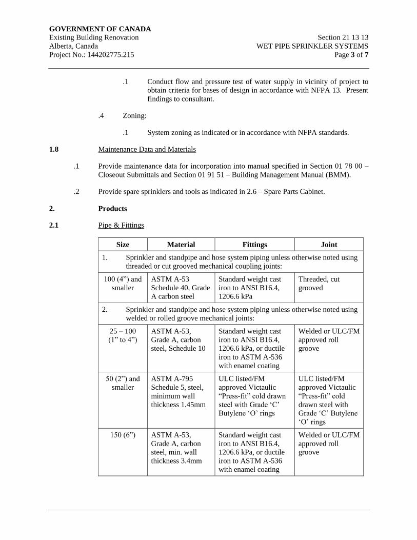
GOVERNMENT OF CANADA Existing Building Renovation Section 21 13 13
Alberta, Canada WET PIPE SPRINKLER SYSTEMS
Project No.: 144202775.215 Page 3 of 7
.1 Conduct flow and pressure test of water supply in vicinity of project to
obtain criteria for bases of design in accordance with NFPA 13. Present
findings to consultant.
.4 Zoning:
.1 System zoning as indicated or in accordance with NFPA standards.
1.8 Maintenance Data and Materials
.1 Provide maintenance data for incorporation into manual specified in Section 01 78 00 –
Closeout Submittals and Section 01 91 51 – Building Management Manual (BMM).
.2 Provide spare sprinklers and tools as indicated in 2.6 – Spare Parts Cabinet.
2. Products
2.1 Pipe & Fittings
Size Material Fittings Joint
1. Sprinkler and standpipe and hose system piping unless otherwise noted using
threaded or cut grooved mechanical coupling joints:
100 (4”) and
smaller
ASTM A-53
Schedule 40, Grade
A carbon steel
Standard weight cast
iron to ANSI B16.4,
1206.6 kPa
Threaded, cut
grooved
2. Sprinkler and standpipe and hose system piping unless otherwise noted using
welded or rolled groove mechanical joints:
25 – 100
(1” to 4”)
ASTM A-53,
Grade A, carbon
steel, Schedule 10
Standard weight cast
iron to ANSI B16.4,
1206.6 kPa, or ductile
iron to ASTM A-536
with enamel coating
Welded or ULC/FM
approved roll
groove
50 (2”) and
smaller
ASTM A-795
Schedule 5, steel,
minimum wall
thickness 1.45mm
ULC listed/FM
approved Victaulic
“Press-fit” cold drawn
steel with Grade ‘C’
Butylene ‘O’ rings
ULC listed/FM
approved Victaulic
“Press-fit” cold
drawn steel with
Grade ‘C’ Butylene
‘O’ rings
150 (6”) ASTM A-53,
Grade A, carbon
steel, min. wall
thickness 3.4mm
Standard weight cast
iron to ANSI B16.4,
1206.6 kPa, or ductile
iron to ASTM A-536
with enamel coating
Welded or ULC/FM
approved roll
groove
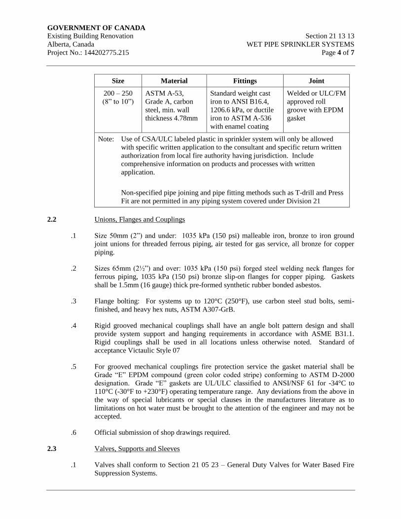
GOVERNMENT OF CANADA Existing Building Renovation Section 21 13 13
Alberta, Canada WET PIPE SPRINKLER SYSTEMS
Project No.: 144202775.215 Page 4 of 7
Size Material Fittings Joint
200 – 250
(8” to 10”)
ASTM A-53,
Grade A, carbon
steel, min. wall
thickness 4.78mm
Standard weight cast
iron to ANSI B16.4,
1206.6 kPa, or ductile
iron to ASTM A-536
with enamel coating
Welded or ULC/FM
approved roll
groove with EPDM
gasket
Note: Use of CSA/ULC labeled plastic in sprinkler system will only be allowed
with specific written application to the consultant and specific return written
authorization from local fire authority having jurisdiction. Include
comprehensive information on products and processes with written
application.
Non-specified pipe joining and pipe fitting methods such as T-drill and Press
Fit are not permitted in any piping system covered under Division 21
2.2 Unions, Flanges and Couplings
.1 Size 50mm (2”) and under: 1035 kPa (150 psi) malleable iron, bronze to iron ground
joint unions for threaded ferrous piping, air tested for gas service, all bronze for copper
piping.
.2 Sizes 65mm (2½”) and over: 1035 kPa (150 psi) forged steel welding neck flanges for
ferrous piping, 1035 kPa (150 psi) bronze slip-on flanges for copper piping. Gaskets
shall be 1.5mm (16 gauge) thick pre-formed synthetic rubber bonded asbestos.
.3 Flange bolting: For systems up to 120°C (250°F), use carbon steel stud bolts, semi-
finished, and heavy hex nuts, ASTM A307-GrB.
.4 Rigid grooved mechanical couplings shall have an angle bolt pattern design and shall
provide system support and hanging requirements in accordance with ASME B31.1.
Rigid couplings shall be used in all locations unless otherwise noted. Standard of
acceptance Victaulic Style 07
.5 For grooved mechanical couplings fire protection service the gasket material shall be
Grade “E” EPDM compound (green color coded stripe) conforming to ASTM D-2000
designation. Grade “E” gaskets are UL/ULC classified to ANSI/NSF 61 for -34°C to
110°C (-30°F to +230°F) operating temperature range. Any deviations from the above in
the way of special lubricants or special clauses in the manufactures literature as to
limitations on hot water must be brought to the attention of the engineer and may not be
accepted.
.6 Official submission of shop drawings required.
2.3 Valves, Supports and Sleeves
.1 Valves shall conform to Section 21 05 23 – General Duty Valves for Water Based Fire
Suppression Systems.
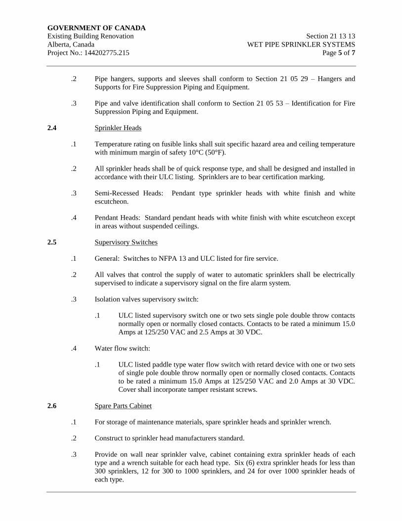
GOVERNMENT OF CANADA Existing Building Renovation Section 21 13 13
Alberta, Canada WET PIPE SPRINKLER SYSTEMS
Project No.: 144202775.215 Page 5 of 7
.2 Pipe hangers, supports and sleeves shall conform to Section 21 05 29 – Hangers and
Supports for Fire Suppression Piping and Equipment.
.3 Pipe and valve identification shall conform to Section 21 05 53 – Identification for Fire
Suppression Piping and Equipment.
2.4 Sprinkler Heads
.1 Temperature rating on fusible links shall suit specific hazard area and ceiling temperature
with minimum margin of safety 10°C (50°F).
.2 All sprinkler heads shall be of quick response type, and shall be designed and installed in
accordance with their ULC listing. Sprinklers are to bear certification marking.
.3 Semi-Recessed Heads: Pendant type sprinkler heads with white finish and white
escutcheon.
.4 Pendant Heads: Standard pendant heads with white finish with white escutcheon except
in areas without suspended ceilings.
2.5 Supervisory Switches
.1 General: Switches to NFPA 13 and ULC listed for fire service.
.2 All valves that control the supply of water to automatic sprinklers shall be electrically
supervised to indicate a supervisory signal on the fire alarm system.
.3 Isolation valves supervisory switch:
.1 ULC listed supervisory switch one or two sets single pole double throw contacts
normally open or normally closed contacts. Contacts to be rated a minimum 15.0
Amps at 125/250 VAC and 2.5 Amps at 30 VDC.
.4 Water flow switch:
.1 ULC listed paddle type water flow switch with retard device with one or two sets
of single pole double throw normally open or normally closed contacts. Contacts
to be rated a minimum 15.0 Amps at 125/250 VAC and 2.0 Amps at 30 VDC.
Cover shall incorporate tamper resistant screws.
2.6 Spare Parts Cabinet
.1 For storage of maintenance materials, spare sprinkler heads and sprinkler wrench.
.2 Construct to sprinkler head manufacturers standard.
.3 Provide on wall near sprinkler valve, cabinet containing extra sprinkler heads of each
type and a wrench suitable for each head type. Six (6) extra sprinkler heads for less than
300 sprinklers, 12 for 300 to 1000 sprinklers, and 24 for over 1000 sprinkler heads of
each type.
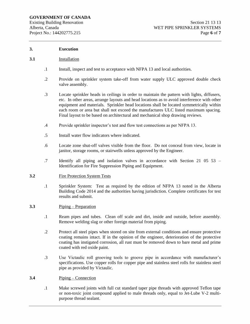
GOVERNMENT OF CANADA Existing Building Renovation Section 21 13 13
Alberta, Canada WET PIPE SPRINKLER SYSTEMS
Project No.: 144202775.215 Page 6 of 7
3. Execution
3.1 Installation
.1 Install, inspect and test to acceptance with NFPA 13 and local authorities.
.2 Provide on sprinkler system take-off from water supply ULC approved double check
valve assembly.
.3 Locate sprinkler heads in ceilings in order to maintain the pattern with lights, diffusers,
etc. In other areas, arrange layouts and head locations as to avoid interference with other
equipment and materials. Sprinkler head locations shall be located symmetrically within
each room or area but shall not exceed the manufactures ULC listed maximum spacing.
Final layout to be based on architectural and mechanical shop drawing reviews.
.4 Provide sprinkler inspector’s test and flow test connections as per NFPA 13.
.5 Install water flow indicators where indicated.
.6 Locate zone shut-off valves visible from the floor. Do not conceal from view, locate in
janitor, storage rooms, or stairwells unless approved by the Engineer.
.7 Identify all piping and isolation valves in accordance with Section 21 05 53 –
Identification for Fire Suppression Piping and Equipment.
3.2 Fire Protection System Tests
.1 Sprinkler System: Test as required by the edition of NFPA 13 noted in the Alberta
Building Code 2014 and the authorities having jurisdiction. Complete certificates for test
results and submit.
3.3 Piping – Preparation
.1 Ream pipes and tubes. Clean off scale and dirt, inside and outside, before assembly.
Remove welding slag or other foreign material from piping.
.2 Protect all steel pipes when stored on site from external conditions and ensure protective
coating remains intact. If in the opinion of the engineer, deterioration of the protective
coating has instigated corrosion, all rust must be removed down to bare metal and prime
coated with red oxide paint.
.3 Use Victaulic roll grooving tools to groove pipe in accordance with manufacturer’s
specifications. Use copper rolls for copper pipe and stainless steel rolls for stainless steel
pipe as provided by Victaulic.
3.4 Piping – Connection
.1 Make screwed joints with full cut standard taper pipe threads with approved Teflon tape
or non-toxic joint compound applied to male threads only, equal to Jet-Lube V-2 multi-
purpose thread sealant.
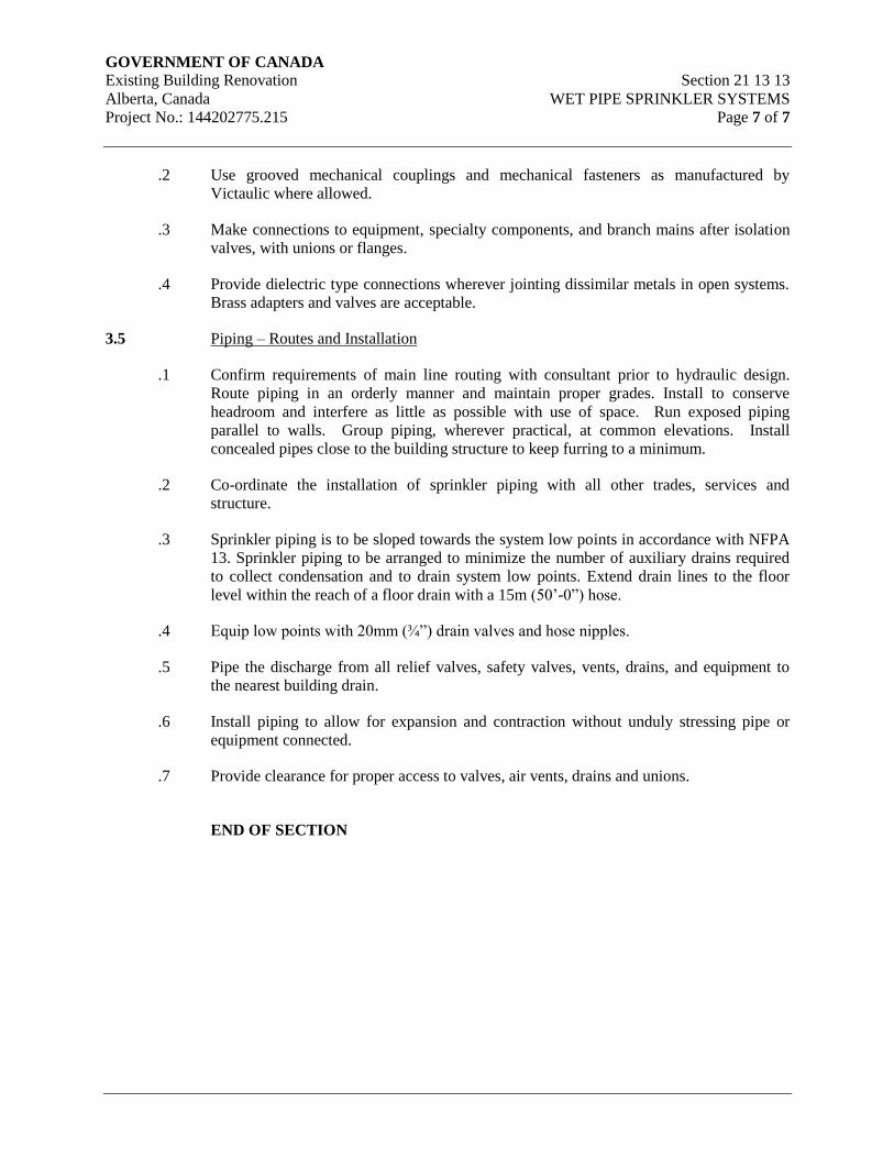
GOVERNMENT OF CANADA Existing Building Renovation Section 21 13 13
Alberta, Canada WET PIPE SPRINKLER SYSTEMS
Project No.: 144202775.215 Page 7 of 7
.2 Use grooved mechanical couplings and mechanical fasteners as manufactured by
Victaulic where allowed.
.3 Make connections to equipment, specialty components, and branch mains after isolation
valves, with unions or flanges.
.4 Provide dielectric type connections wherever jointing dissimilar metals in open systems.
Brass adapters and valves are acceptable.
3.5 Piping – Routes and Installation
.1 Confirm requirements of main line routing with consultant prior to hydraulic design.
Route piping in an orderly manner and maintain proper grades. Install to conserve
headroom and interfere as little as possible with use of space. Run exposed piping
parallel to walls. Group piping, wherever practical, at common elevations. Install
concealed pipes close to the building structure to keep furring to a minimum.
.2 Co-ordinate the installation of sprinkler piping with all other trades, services and
structure.
.3 Sprinkler piping is to be sloped towards the system low points in accordance with NFPA
13. Sprinkler piping to be arranged to minimize the number of auxiliary drains required
to collect condensation and to drain system low points. Extend drain lines to the floor
level within the reach of a floor drain with a 15m (50’-0”) hose.
.4 Equip low points with 20mm (¾”) drain valves and hose nipples.
.5 Pipe the discharge from all relief valves, safety valves, vents, drains, and equipment to
the nearest building drain.
.6 Install piping to allow for expansion and contraction without unduly stressing pipe or
equipment connected.
.7 Provide clearance for proper access to valves, air vents, drains and unions.
END OF SECTION
GOVERNMENT OF CANADA Existing Building Renovation Section 21 13 19
Alberta, Canada PREACTION SPRINKLER SYSTEMS
Project No.: 144202775.215 Page 1 of 10
1. General
1.1 Scope
.1 Equipment, piping, including sprinkler heads, valves, hangers and supports, sleeves, fire
department connections, and accessories.
.2 Contractor shall be responsible for coordination of all fire alarm interlocks with Division
26.
1.2 General Requirements
.1 Provide complete sprinkler system as required by local codes and as indicated on
drawings. Size of sprinkler system based on light hazard occupancy.
.2 Provide sprinklers for areas as indicated and as required, including specialized rooms.
Run piping concealed above furred ceilings and in joist to minimize obstructions. Expose
only heads.
.3 Hydraulically size sprinkler system based on the actual water supply data which must be
obtained from municipal utility.
1.3 Quality Assurance
.1 All municipal bylaws, provincial statutes and NFPA Standards governing the installation
shall be strictly adhered to.
.2 Provide all labor and materials in accordance with the requirements of the fire marshal
having jurisdiction. Comply fully with the rules and regulations stated in current
National Building Code and the following NFPA Standards, those editions which are in
effect locally and in the Province of Alberta.
.3 Guarantee that the quantities of sprinklers proposed meet the requirements of this
specification. If the quantities are not within these requirements, provide additional
sprinklers and their installation at no additional cost to the contract.
.4 Sprinkler equipment and installation shall be in accordance with the current standards
required by IAO, Insurers Advisory Organization, Owner's Underwriters, Factory
Mutual, and approved local Fire Commissioner.
.5 Equipment and installation shall meet the requirements of current edition of NFPA 13 -
Standard for the Installation of Sprinkler Systems.
.6 Sprinkler equipment shall be installed by qualified contractors licensed and regularly
engaged in installation of automatic fire sprinkler equipment.
1.4 Reference Standards
.1 National Fire Protection Association (NFPA)
GOVERNMENT OF CANADA Existing Building Renovation Section 21 13 19
Alberta, Canada PREACTION SPRINKLER SYSTEMS
Project No.: 144202775.215 Page 2 of 10
.1 NFPA 13 Standard for the Installation of Sprinkler Systems
.2 National Research Council (NRC)
.1 Alberta Building Code (ABC) 2014
.2 National Building Code (NBC) 2010
.3 National Plumbing Code of Canada (NPC) 2010
1.5 Submittals
.1 Submit four (4) copies of the preliminary layout showing head locations, pipe sizes, and
pipe route for review by the consultant. Furnish additional heads which may be required
for coordinated ceiling pattern without added cost, even though number of heads may
exceed minimum code requirements.
.2 Submit to the consultant shop drawings and sprinkler hydraulic calculations bearing the
approval seal of Professional Engineer specialized in Fire Protection.
.3 Submit cut sheets of equipment and accessories related to the sprinkler system, and
appurtenances for Consultant’s approval.
.4 Submit completed hydrostatic test certificates and other certification of testing as
required and to the owner’s Underwriter.
1.6 Related Work Specified in Other Sections
.1 Common Work Results for Fire Suppression Section 21 05 00
.2 Wet Pipe Fire Suppression Sprinkler Systems Section 21 13 13
1.7 Engineering Design Criteria
.1 Design system in accordance with NFPA 13, using following parameters:
.1 Hazard: To suit occupancy classification based on the quantity and/or
combustibility of the building contents.
.2 Pipe size and layout:
.1 Hydraulic design in accordance with NFPA standards and the Owner’s
Insurance Underwriter requirements, which ever is more stringent.
.2 Sprinkler head layout: to NFPA 13 or as directed by Authority Having
Jurisdiction.]
.3 Water Supply
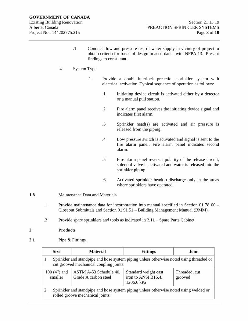
GOVERNMENT OF CANADA Existing Building Renovation Section 21 13 19
Alberta, Canada PREACTION SPRINKLER SYSTEMS
Project No.: 144202775.215 Page 3 of 10
.1 Conduct flow and pressure test of water supply in vicinity of project to
obtain criteria for bases of design in accordance with NFPA 13. Present
findings to consultant.
.4 System Type
.1 Provide a double-interlock preaction sprinkler system with
electrical activation. Typical sequence of operation as follows:
.1 Initiating device circuit is activated either by a detector
or a manual pull station.
.2 Fire alarm panel receives the initiating device signal and
indicates first alarm.
.3 Sprinkler head(s) are activated and air pressure is
released from the piping.
.4 Low pressure switch is activated and signal is sent to the
fire alarm panel. Fire alarm panel indicates second
alarm.
.5 Fire alarm panel reverses polarity of the release circuit,
solenoid valve is activated and water is released into the
sprinkler piping.
.6 Activated sprinkler head(s) discharge only in the areas
where sprinklers have operated.
1.8 Maintenance Data and Materials
.1 Provide maintenance data for incorporation into manual specified in Section 01 78 00 –
Closeout Submittals and Section 01 91 51 – Building Management Manual (BMM).
.2 Provide spare sprinklers and tools as indicated in 2.11 – Spare Parts Cabinet.
2. Products
2.1 Pipe & Fittings
Size Material Fittings Joint
1. Sprinkler and standpipe and hose system piping unless otherwise noted using threaded or
cut grooved mechanical coupling joints:
100 (4”) and
smaller
ASTM A-53 Schedule 40,
Grade A carbon steel
Standard weight cast
iron to ANSI B16.4,
1206.6 kPa
Threaded, cut
grooved
2. Sprinkler and standpipe and hose system piping unless otherwise noted using welded or
rolled groove mechanical joints:
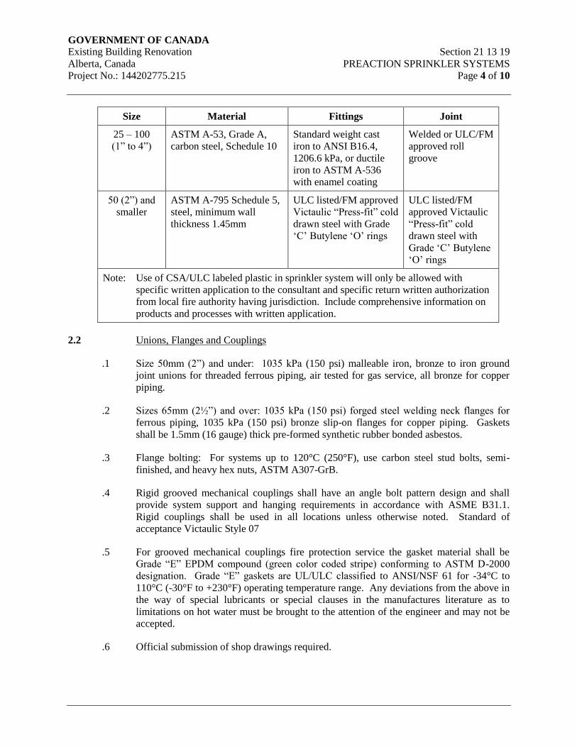
GOVERNMENT OF CANADA Existing Building Renovation Section 21 13 19
Alberta, Canada PREACTION SPRINKLER SYSTEMS
Project No.: 144202775.215 Page 4 of 10
Size Material Fittings Joint
25 – 100
(1” to 4”)
ASTM A-53, Grade A,
carbon steel, Schedule 10
Standard weight cast
iron to ANSI B16.4,
1206.6 kPa, or ductile
iron to ASTM A-536
with enamel coating
Welded or ULC/FM
approved roll
groove
50 (2”) and
smaller
ASTM A-795 Schedule 5,
steel, minimum wall
thickness 1.45mm
ULC listed/FM approved
Victaulic “Press-fit” cold
drawn steel with Grade
‘C’ Butylene ‘O’ rings
ULC listed/FM
approved Victaulic
“Press-fit” cold
drawn steel with
Grade ‘C’ Butylene
‘O’ rings
Note: Use of CSA/ULC labeled plastic in sprinkler system will only be allowed with
specific written application to the consultant and specific return written authorization
from local fire authority having jurisdiction. Include comprehensive information on
products and processes with written application.
2.2 Unions, Flanges and Couplings
.1 Size 50mm (2”) and under: 1035 kPa (150 psi) malleable iron, bronze to iron ground
joint unions for threaded ferrous piping, air tested for gas service, all bronze for copper
piping.
.2 Sizes 65mm (2½”) and over: 1035 kPa (150 psi) forged steel welding neck flanges for
ferrous piping, 1035 kPa (150 psi) bronze slip-on flanges for copper piping. Gaskets
shall be 1.5mm (16 gauge) thick pre-formed synthetic rubber bonded asbestos.
.3 Flange bolting: For systems up to 120°C (250°F), use carbon steel stud bolts, semi-
finished, and heavy hex nuts, ASTM A307-GrB.
.4 Rigid grooved mechanical couplings shall have an angle bolt pattern design and shall
provide system support and hanging requirements in accordance with ASME B31.1.
Rigid couplings shall be used in all locations unless otherwise noted. Standard of
acceptance Victaulic Style 07
.5 For grooved mechanical couplings fire protection service the gasket material shall be
Grade “E” EPDM compound (green color coded stripe) conforming to ASTM D-2000
designation. Grade “E” gaskets are UL/ULC classified to ANSI/NSF 61 for -34°C to
110°C (-30°F to +230°F) operating temperature range. Any deviations from the above in
the way of special lubricants or special clauses in the manufactures literature as to
limitations on hot water must be brought to the attention of the engineer and may not be
accepted.
.6 Official submission of shop drawings required.
GOVERNMENT OF CANADA Existing Building Renovation Section 21 13 19
Alberta, Canada PREACTION SPRINKLER SYSTEMS
Project No.: 144202775.215 Page 5 of 10
2.3 Valves, Supports and Sleeves
.1 Valves shall conform to Section 21 05 23 – General Duty Valves for Water Based Fire
Suppression Systems.
.2 Pipe hangers, supports and sleeves shall conform to Section 21 05 29 – Hangers and
Supports for Fire Suppression Piping and Equipment.
.3 Pipe and valve identification shall conform to Section 21 05 53 – Identification for Fire
Suppression Piping and Equipment.
2.4 Sprinkler Heads
.1 Temperature rating on fusible links shall suit specific hazard area and ceiling temperature
with minimum margin of safety 10°C (50°F).
.2 All sprinkler heads shall be of quick response type, and shall be designed and installed in
accordance with their ULC listing. Sprinklers are to bear certification marking.
.3 Upright Heads: Standard upright, brass finish.
.4 Sidewall Heads: Standard sidewall heads with chrome plated finish and chrome plated
escutcheon.
2.5 Supervisory Switches
.1 General: Switches to NFPA 13 and ULC listed for fire service.
.2 All valves that control the supply of water to automatic sprinklers shall be electrically
supervised to indicate a supervisory signal on the fire alarm system.
.3 Isolation Valves Supervisory Switch:
.1 ULC listed supervisory switch one or two sets single pole double throw contacts
normally open or normally closed contacts. Contacts to be rated a minimum 15.0
Amps at 125/250 VAC and 2.5 Amps at 30 VDC.
.4 Pressure Alarm Switch:
.1 ULC listed with one or two sets single pole double throw contacts normally open
or normally closed contacts. Pressure switch cover shall incorporate tamper
resistant screws. Contacts to be rated a minimum 15.0 Amps at 125/250 VAC
and 2.5 Amps at 30 VDC.
.5 Low Pressure Alarm Switch:
.1 ULC listed with one or two sets single pole double throw contacts normally open
or normally closed contacts. Pressure switch cover shall incorporate tamper
resistant screws. Contacts to be rated a minimum 15.0 Amps at 125/250 VAC
and 2.5 Amps at 30 VDC.
GOVERNMENT OF CANADA Existing Building Renovation Section 21 13 19
Alberta, Canada PREACTION SPRINKLER SYSTEMS
Project No.: 144202775.215 Page 6 of 10
.6 Solenoid Valve:
.1 Provide a 24 VDC rated solenoid valve listed for use with the electrical actuation
trim provided.
2.6 Preaction Valve Release Panel
.1 Panel shall be provided by Division 21 and installed by Division 26. The panel must be
by the same manufacturer as the base building fire alarm panel.
.2 Panel shall be housed in a wall-mounted enclosure with hinged door that is provided with
a keyed lock. The panel shall be ULC approved and comply with NFPA 72.
.3 The following circuits shall be provided:
.1 A supervised signal initiating device circuit for manual pull stations, smoke
detectors and/or heat detectors. This circuit shall be selectable to style D (class
A) or style B (class B).
.2 A supervised signal indicating device circuit that will reverse polarity when an
alarm condition occurs. This circuit shall be rated ½ ampere at 24 VDC.
.3 A separate supervised style B (class B) circuit to monitor control valve position,
low air pressure in supervised preaction piping and alarm pressure switch
(system has tripped).
.4 A style B (class B) supervised solenoid release circuit that shall reverse polarity
when a releasing condition occurs. This circuit shall be rated 1.0 ampere at
24VDC.
.4 Provide visual indicators that are visible with the panel door closed as follows:
.1 AC On – Green LED
.2 Alarm – Red LED
.3 System Trouble – Yellow LED
.4 Supervisory Condition – Yellow LED
.5 Signal Indicating device silenced – Yellow LED
.5 Provide the following panel features:
.1 A built in trouble buzzer.
.2 Silence switch that silences alarm indicating devices or the trouble buzzer and
resets trouble relay contacts.
.3 Manual release switch that activates all alarm indicators, alarm and releasing
circuit outputs.
GOVERNMENT OF CANADA Existing Building Renovation Section 21 13 19
Alberta, Canada PREACTION SPRINKLER SYSTEMS
Project No.: 144202775.215 Page 7 of 10
.4 Releasing circuit disable switch that prevents operation of the releasing circuit.
.5 A test switch that disables the latching function of the signal initiating device
circuit.
.6 Reset switch that restores the panel to normal after the initiating device circuit
has been cleared.
.7 One set of SPDT (form C) auxiliary alarm contacts and one set SPST (Form A)
auxiliary trouble contacts, rated 2 amperes at 30 volts AC/DC.
.8 Provide a secondary power supply in accordance with NFPA 72. The power
supply shall be a combination power supply/battery charger with standby
batteries capable of operating the system for up to 24 hours under maximum
quiescent load (system functioning in a non-alarm condition).
.9 Defects in the system which may cause failure or impair operation of the system
shall cause these conditions to be annunciated as follows:
.10 Failure of any electrical power either primary or battery shall cause a visual and
audible trouble signal on the control panel annunciator panel.
.11 Open circuits in any fire detector wiring or removal of any detector shall cause an
audible signal and visually annunciate the specific zone where the fault is
located.
.12 Open circuits in initiator wiring or the silencing of the alarm sounding devices
shall cause an audible and visual trouble signal at the control panel and
annunciator panel.
2.7 Preaction Alarm Valve
.1 Provide a ULC approved preaction valve complete with all devices and drain valves.
2.8 Air Maintenance Device
.1 Provide a ULC listed air maintenance device complete with isolation valves, strainer, air
pressure regulator, restriction orifice and bypass.
2.9 Air Compressor
.1 Provide electric drive, horizontal tank mounted, single stage compressor, capable of
restoring normal system air pressure within 30 minutes, two (2) pole air pressure operated
electric pressure switch with 2-way release or breather valve, safety valve, check valve,
automatic tank drain, belt guard and controls.
.2 Air compressor is to be supplied with magnetic starter and the compressor motor is to be
120 volt, 1 phase, 60 Hertz.
GOVERNMENT OF CANADA Existing Building Renovation Section 21 13 19
Alberta, Canada PREACTION SPRINKLER SYSTEMS
Project No.: 144202775.215 Page 8 of 10
2.10 Pressure Gauges
.1 Gauges to be ULC listed.
.2 Shall have maximum limit of not less than twice normal working pressure at point where
installed.
.3 A pressure gauge with a connection not smaller than 6mm (1/4”). shall be installed at the
system main drain, at each main drain associated with a floor control valve, and on the
inlet and outlet side of each pressure-reducing valve. Each gauge connection shall be
equipped with a shutoff valve and provisions for draining.
2.11 Spare Parts Cabinet
.1 For storage of maintenance materials, spare sprinkler heads and sprinkler wrench.
.2 Construct to sprinkler head manufacturers standard.
.3 Provide on wall near sprinkler valve, cabinet containing extra sprinkler heads of each
type and a wrench suitable for each head type. Six (6) extra sprinkler heads for less than
300 sprinklers, 12 for 300 to 1000 sprinklers, and 24 for over 1000 sprinkler heads of
each type.
3. Execution
3.1 Installation
.1 Install, inspect and test to acceptance with NFPA 13 and local authorities.
.2 All sprinkler system isolation valves shall have fire alarm contacts that can be monitored
on the building fire alarm system. Coordinate contact type and wiring with Division 26.
.3 Locate sprinkler heads in ceilings in order to maintain the pattern with lights, diffusers,
etc. In other areas, arrange layouts and head locations as to avoid interference with other
equipment and materials. Sprinkler head locations shall be located symmetrically within
each room or area but shall not exceed the manufactures ULC listed maximum spacing.
Final layout to be based on architectural and mechanical shop drawing reviews.
.4 Provide sprinkler inspector’s test and flow test connections as per NFPA 13.
.5 Install water flow indicators where indicated.
.6 Locate zone shut-off valves visible from the floor. Do not conceal from view, locate in
janitor, storage rooms, or stairwells unless approved by the Engineer.
.7 Identify all piping and isolation valves in accordance with Section 21 05 53 –
Identification for Fire Suppression Piping and Equipment.
GOVERNMENT OF CANADA Existing Building Renovation Section 21 13 19
Alberta, Canada PREACTION SPRINKLER SYSTEMS
Project No.: 144202775.215 Page 9 of 10
3.2 Fire Protection System Tests
.1 Sprinkler System: Test as required by the edition of NFPA 13 noted in the Alberta
Building Code 2014 and the authorities having jurisdiction. Complete certificates for test
results and submit.
3.3 Piping – Preparation
.1 Ream pipes and tubes. Clean off scale and dirt, inside and outside, before assembly.
Remove welding slag or other foreign material from piping.
.2 Protect all steel pipes when stored on site from external conditions and ensure protective
coating remains intact. If in the opinion of the engineer, deterioration of the protective
coating has instigated corrosion, all rust must be removed down to bare metal and prime
coated with red oxide paint.
.3 Use Victaulic roll grooving tools to groove pipe in accordance with manufacturer’s
specifications. Use copper rolls for copper pipe and stainless steel rolls for stainless steel
pipe as provided by Victaulic.
3.4 Piping – Connection
.1 Make screwed joints with full cut standard taper pipe threads with approved Teflon tape
or non-toxic joint compound applied to male threads only, equal to Jet-Lube V-2 multi-
purpose thread sealant.
.2 Use grooved mechanical couplings and mechanical fasteners as manufactured by
Victaulic where allowed.
.3 Make connections to equipment, specialty components, and branch mains after isolation
valves, with unions or flanges.
.4 Provide dielectric type connections wherever jointing dissimilar metals in open systems.
Brass adapters and valves are acceptable.
3.5 Piping – Routes and Installation
.1 Confirm requirements of main line routing with consultant prior to hydraulic design.
Route piping in an orderly manner and maintain proper grades. Install to conserve
headroom and interfere as little as possible with use of space. Run exposed piping
parallel to walls. Group piping, wherever practical, at common elevations. Install
concealed pipes close to the building structure to keep furring to a minimum.
.2 Co-ordinate the installation of sprinkler piping with all other trades, services and
structure.
.3 Sprinkler piping is to be sloped towards the system low points in accordance with NFPA
13. Sprinkler piping to be arranged to minimize the number of auxiliary drains required
to collect condensation and to drain system low points. Extend drain lines to the floor
level within the reach of a floor drain with a 15m (50’-0”) hose.
GOVERNMENT OF CANADA Existing Building Renovation Section 21 13 19
Alberta, Canada PREACTION SPRINKLER SYSTEMS
Project No.: 144202775.215 Page 10 of 10
.4 Equip low points with 20mm (¾”) drain valves and hose nipples.
.5 Pipe the discharge from all relief valves, safety valves, vents, drains, and equipment to
the nearest building drain.
.6 Install piping to allow for expansion and contraction without unduly stressing pipe or
equipment connected.
.7 Provide clearance for proper access to valves, air vents, drains and unions.
END OF SECTION
GOVERNMENT OF CANADA Existing Building Renovation Section 22 01 10.51
Alberta, Canada PLUMBING PIPING CLEANING
Project No.: 144202775.215 Page 1 of 3
1. General
1.1 Scope
.1 Provide for flushing and disinfection of domestic water systems.
.2 Isolate and bypass equipment listed in Clause 3.1.
1.2 Quality Assurance
.1 Provide chemical treatment, chemicals and equipment by an agency that specializes in
this type of work. This work shall be directed by the water treatment agency who, upon
completion, shall certify that the process is satisfactory and submit a report outlining the
cleaning operation and the treatment process.
.2 Provide chemical treatment as specified herein and provide written reports. Reports shall
be signed by the chemical treatment agency, mechanical contractor and commissioning
agency.
.3 Include for the costs of an independent testing agency, selected by the Owner, to take
samples of domestic water, perform lab analysis of the chemical treatment levels, and
submit a written report of their findings to the Owner. Should the lab results prove that
standards for drinking water quality have not been met, the Contractor shall correct the
deficiency and cover the costs of the independent testing agency to take additional
samples and tests.
.4 All equipment, service and chemicals shall be from one supplier.
1.3 Submittals
.1 Submit shop drawings including proposed chemicals, quantities, procedures and analysis
reports to be used on this project. Provide written operating instructions and system
schematics.
.2 Provide written reports containing log and procedure of system cleaning and degreasing,
giving times, dates, conditions of water and problems and actions encountered.
.3 Submit a written report on system operations.
1.4 Chemical Treatment Agency
.1 Chemical treatment agency shall provide equipment, chemicals and site supervision so as
to fully comply with all requirements and their intent contained within this specification
section.
GOVERNMENT OF CANADA Existing Building Renovation Section 22 01 10.51
Alberta, Canada PLUMBING PIPING CLEANING
Project No.: 144202775.215 Page 2 of 3
2. Products
2.1 Materials
.1 Provide sufficient chemicals to treat domestic water systems and test the systems from
the time of activation and acceptance of the building.
.2 Chemicals used must comply with environmental and health standards applicable to the
usage on this project.
.3 Domestic Water System: Sodium hypochlorite conforms to ANSI/AWWA B301.
3. Execution
3.1 Piping General
.1 Ensure reasonable care is exercised to prevent debris, dirt and other foreign material from
entering the pipe during construction. This is to include proper protection of piping on
site prior to installation, temporary caps on partial systems, and complete evacuation of
moisture within systems being hydrostatically pressure tested.
.2 Chemical treatment agency shall, in conjunction with the mechanical contractor, review
connections for complete draining and venting of the systems. The mechanical
contractor shall provide adequate drain connections to completely drain the systems
within one hour.
.3 Protect and/or remove control devices from systems during cleaning. All terminal
control valves shall be in open position during cleaning. Particular attention is to be
made to control valves which have a normally closed position.
.4 Make systems completely operational, totally filled, thoroughly vented, and completely
started.
3.2 System Cleaning
.1 Pipes intended to carry potable water shall be disinfected before being placed in service.
Disinfection procedures shall conform to AWWA C651 as hereinafter modified or
expanded, and the requirements of any governing agency having jurisdiction.
.2 Flushing
.1 Before disinfecting, the mechanical contractor shall flush all foreign matter from
the pipeline. He/she shall provide hoses, pumps, temporary pipes, ditches, etc., as
required to dispose of flushing water without causing damage to adjacent
properties. The flushing velocities shall be at least 2.5 FPS. For large diameter
pipe, where it is impractical or impossible to flush the pipe at 2.5 FPS velocity,
the pipeline shall be cleaned in place from the inside by brushing and sweeping,
then flushing the line at a lower velocity.
.3 Disinfection Mixture
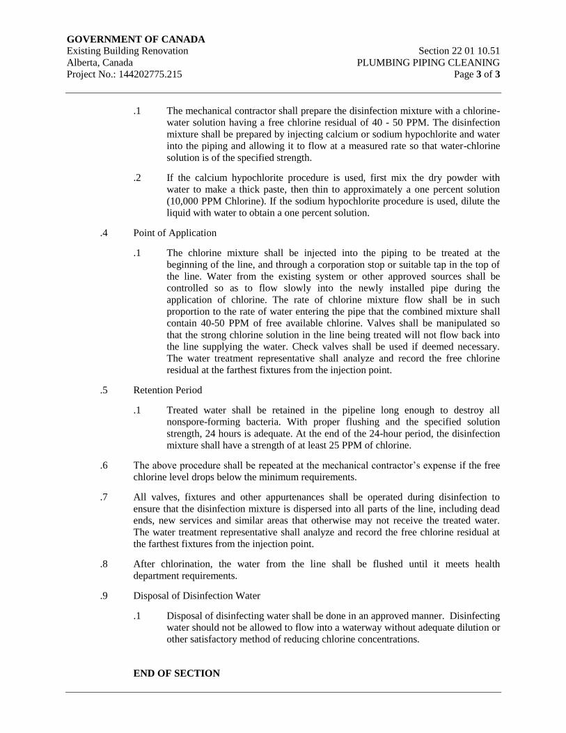
GOVERNMENT OF CANADA Existing Building Renovation Section 22 01 10.51
Alberta, Canada PLUMBING PIPING CLEANING
Project No.: 144202775.215 Page 3 of 3
.1 The mechanical contractor shall prepare the disinfection mixture with a chlorine-
water solution having a free chlorine residual of 40 - 50 PPM. The disinfection
mixture shall be prepared by injecting calcium or sodium hypochlorite and water
into the piping and allowing it to flow at a measured rate so that water-chlorine
solution is of the specified strength.
.2 If the calcium hypochlorite procedure is used, first mix the dry powder with
water to make a thick paste, then thin to approximately a one percent solution
(10,000 PPM Chlorine). If the sodium hypochlorite procedure is used, dilute the
liquid with water to obtain a one percent solution.
.4 Point of Application
.1 The chlorine mixture shall be injected into the piping to be treated at the
beginning of the line, and through a corporation stop or suitable tap in the top of
the line. Water from the existing system or other approved sources shall be
controlled so as to flow slowly into the newly installed pipe during the
application of chlorine. The rate of chlorine mixture flow shall be in such
proportion to the rate of water entering the pipe that the combined mixture shall
contain 40-50 PPM of free available chlorine. Valves shall be manipulated so
that the strong chlorine solution in the line being treated will not flow back into
the line supplying the water. Check valves shall be used if deemed necessary.
The water treatment representative shall analyze and record the free chlorine
residual at the farthest fixtures from the injection point.
.5 Retention Period
.1 Treated water shall be retained in the pipeline long enough to destroy all
nonspore-forming bacteria. With proper flushing and the specified solution
strength, 24 hours is adequate. At the end of the 24-hour period, the disinfection
mixture shall have a strength of at least 25 PPM of chlorine.
.6 The above procedure shall be repeated at the mechanical contractor’s expense if the free
chlorine level drops below the minimum requirements.
.7 All valves, fixtures and other appurtenances shall be operated during disinfection to
ensure that the disinfection mixture is dispersed into all parts of the line, including dead
ends, new services and similar areas that otherwise may not receive the treated water.
The water treatment representative shall analyze and record the free chlorine residual at
the farthest fixtures from the injection point.
.8 After chlorination, the water from the line shall be flushed until it meets health
department requirements.
.9 Disposal of Disinfection Water
.1 Disposal of disinfecting water shall be done in an approved manner. Disinfecting
water should not be allowed to flow into a waterway without adequate dilution or
other satisfactory method of reducing chlorine concentrations.
END OF SECTION

GOVERNMENT OF CANADA Existing Building Renovation Section 22 05 00
Alberta, Canada COMMON WORK RESULTS
Project No.: 144202775.215 FOR PLUMBING
Page 1 of 2
1. General
1.1 Intent
.1 Work in Division 22 will include all drawings and all sections of the specifications that
form the Contract Documents, including all addenda, and including Division 00 and
Division 01, whether defined in Division 22 or elsewhere, or whether defined in
mechanical drawings or elsewhere.
.2 Provide complete, fully tested and operational mechanical systems to meet requirements
described herein and in complete accord with applicable codes and ordinances. Include
all costs to obtain all permits and to pay for all fees and charges, including inspection
charges by the authorities that issue the permits. Coordinate all related inspections.
Permits, fees and inspections including:
.1 Water treatment
.2 Building plumbing
.3 Contract documents consisting of the specifications and drawings, are generally
diagrammatic and approximately to scale unless detailed otherwise. They establish
scope, material and installation quality and are not detailed installation instructions.
.4 Review Contract Documents and notify the Consultant of issues or conflict that require
clarification prior to submitting tender. Failure by the Contractor to secure clarification
does not relieve the Contractor to comply with the intent of the design and/or the
Contract Document.
1.2 Related Requirements
.1 Refer to and comply with the following sections:
.1 General Requirements Division 01
.2 Submittal Procedures Section 01 33 00
.3 Delegated Design Submittals Section 01 33 50
.4 Quality Control Section 01 45 00
.5 Temporary Utilities Section 01 51 00
.6 Closeout Procedures Section 01 77 00
.7 Closeout Submittals Section 01 78 00
.8 Demonstration and Training Section 01 79 00
.9 Commissioning Section 01 91 00
.10 Commissioning (Cx) Plan Section 01 91 31
.11 Building Management Manual Section 01 91 51
GOVERNMENT OF CANADA Existing Building Renovation Section 22 05 00
Alberta, Canada COMMON WORK RESULTS
Project No.: 144202775.215 FOR PLUMBING
Page 2 of 2
1.3 Related Work Specified In Other Sections
.1 For complete common work requirements refer to Section 23 05 00 – Common Work
Results for HVAC.
2. Products
.1 For complete Common Work requirements refer to Section 23 05 00 – Common Work
Results for HVAC.
3. Execution
.1 For complete Common Work requirements refer to Section 23 05 00 – Common Work
Results for HVAC.
END OF SECTION
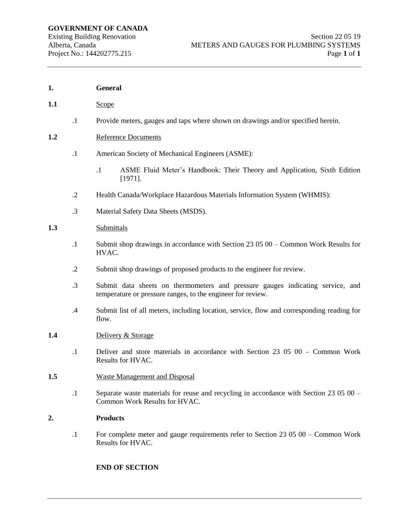
GOVERNMENT OF CANADA Existing Building Renovation Section 22 05 19
Alberta, Canada METERS AND GAUGES FOR PLUMBING SYSTEMS
Project No.: 144202775.215 Page 1 of 1
1. General
1.1 Scope
.1 Provide meters, gauges and taps where shown on drawings and/or specified herein.
1.2 Reference Documents
.1 American Society of Mechanical Engineers (ASME):
.1 ASME Fluid Meter’s Handbook: Their Theory and Application, Sixth Edition
[1971].
.2 Health Canada/Workplace Hazardous Materials Information System (WHMIS):
.3 Material Safety Data Sheets (MSDS).
1.3 Submittals
.1 Submit shop drawings in accordance with Section 23 05 00 – Common Work Results for
HVAC.
.2 Submit shop drawings of proposed products to the engineer for review.
.3 Submit data sheets on thermometers and pressure gauges indicating service, and
temperature or pressure ranges, to the engineer for review.
.4 Submit list of all meters, including location, service, flow and corresponding reading for
flow.
1.4 Delivery & Storage
.1 Deliver and store materials in accordance with Section 23 05 00 – Common Work
Results for HVAC.
1.5 Waste Management and Disposal
.1 Separate waste materials for reuse and recycling in accordance with Section 23 05 00 –
Common Work Results for HVAC.
2. Products
.1 For complete meter and gauge requirements refer to Section 23 05 00 – Common Work
Results for HVAC.
END OF SECTION
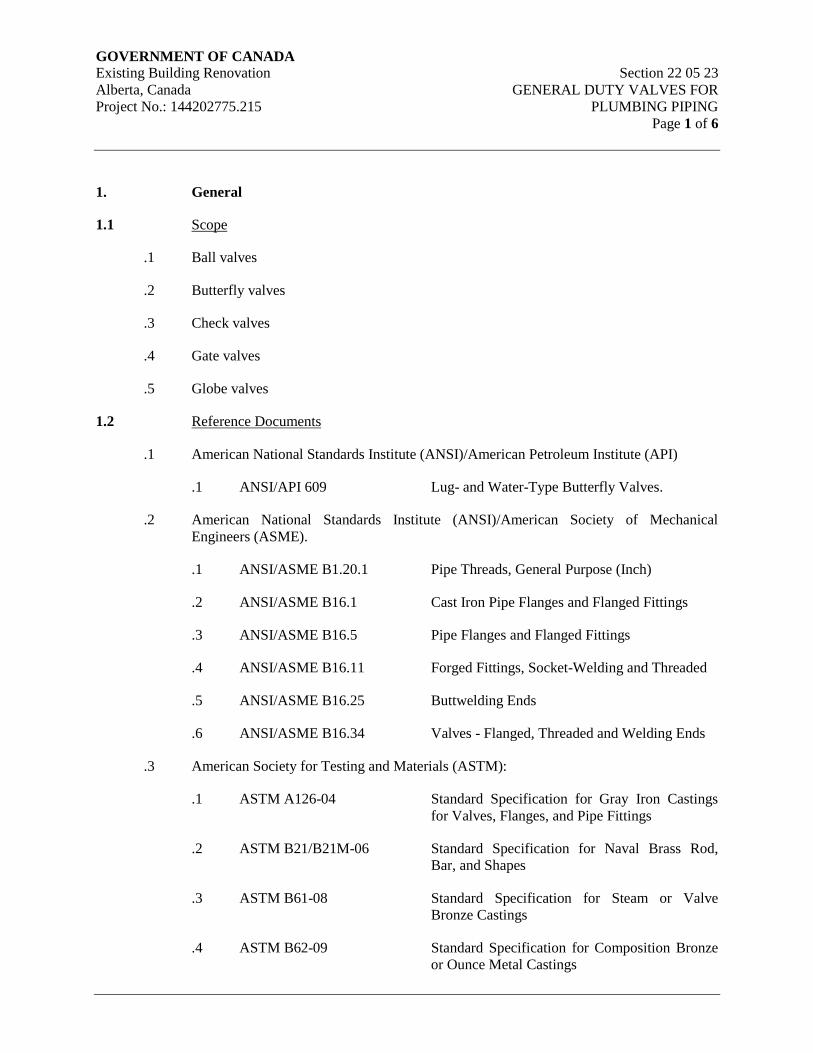
GOVERNMENT OF CANADA Existing Building Renovation Section 22 05 23
Alberta, Canada GENERAL DUTY VALVES FOR
Project No.: 144202775.215 PLUMBING PIPING
Page 1 of 6
1. General
1.1 Scope
.1 Ball valves
.2 Butterfly valves
.3 Check valves
.4 Gate valves
.5 Globe valves
1.2 Reference Documents
.1 American National Standards Institute (ANSI)/American Petroleum Institute (API)
.1 ANSI/API 609 Lug- and Water-Type Butterfly Valves.
.2 American National Standards Institute (ANSI)/American Society of Mechanical
Engineers (ASME).
.1 ANSI/ASME B1.20.1 Pipe Threads, General Purpose (Inch)
.2 ANSI/ASME B16.1 Cast Iron Pipe Flanges and Flanged Fittings
.3 ANSI/ASME B16.5 Pipe Flanges and Flanged Fittings
.4 ANSI/ASME B16.11 Forged Fittings, Socket-Welding and Threaded
.5 ANSI/ASME B16.25 Buttwelding Ends
.6 ANSI/ASME B16.34 Valves - Flanged, Threaded and Welding Ends
.3 American Society for Testing and Materials (ASTM):
.1 ASTM A126-04 Standard Specification for Gray Iron Castings
for Valves, Flanges, and Pipe Fittings
.2 ASTM B21/B21M-06 Standard Specification for Naval Brass Rod,
Bar, and Shapes
.3 ASTM B61-08 Standard Specification for Steam or Valve
Bronze Castings
.4 ASTM B62-09 Standard Specification for Composition Bronze
or Ounce Metal Castings
GOVERNMENT OF CANADA Existing Building Renovation Section 22 05 23
Alberta, Canada GENERAL DUTY VALVES FOR
Project No.: 144202775.215 PLUMBING PIPING
Page 2 of 6
.5 ASTM B98/B98M-08 Standard Specification for Copper-Silicon Alloy
Rod, Bar and Shapes
.6 ASTM B139/B139M-07 Standard Specification for Phosphor Bronze
Rod, Bar, and Shapes
.4 National Plumbing Code of Canada 2010
.5 National Fire Protection Association (NFPA):
.1 NFPA 13-2010 Standard for the Installation of Sprinkler
Systems
.2 NFPA 14-2007 Standard for the Installation of Standpipe
Systems
.6 Manufacturers Standardization Society Standard Practices (Current Editions)
.1 SP-67 Butterfly Valves
.2 SP-70 Gray Iron Gate Valves, Flanged and Threaded
Ends
.3 SP-71 Gray Iron Swing Check Valves, Flanged and
Threaded Ends
.4 SP-80 Bronze Gate, Globe, Angle, and Check Valves
.5 SP-82 Valve Pressure Testing Methods
.6 SP-110 Ball Valves, Threaded Socket-Welding, Solder
Joint, Grooved and Flared Ends
1.3 Manufacturer
.1 Provide valves of the same type by the same manufacturer throughout.
.2 Valves shall bear the following information permanently marked on the valve body”
.1 Manufacturer’s name or trademark
.2 Pressure rating
.3 Flow direction
.3 Valves for fire protection service to be ULC Listed and FM Approved.
1.4 Shop Drawings
.1 Submit detailed shop drawings clearly indicating, at a minimum, the following:
GOVERNMENT OF CANADA Existing Building Renovation Section 22 05 23
Alberta, Canada GENERAL DUTY VALVES FOR
Project No.: 144202775.215 PLUMBING PIPING
Page 3 of 6
.1 Manufacturer
.2 Model
.3 Size
.4 Pressure rating
.5 Materials of construction
.6 Intended service
2. Products
.1 For complete General Duty Valve requirements refer to Section 23 05 23 – General Duty
Valves for HVAC Piping.
2.2 Acceptable Manufacturers
.1 Ball Valves : Crane, Jenking, Kitz, Legend, Nibco, MAS,
Milwaukee, Toyo
.2 Butterfly Valves :Apollo, Centerline, Jenkins, Keystone, Victaulic
.3 Check Valves – Swing : Crane, Jenkins, Kitz, Milwaukee, Moygro,
Mueller, Nibco, Toyo, Victaulic
.4 Gate Valves : Crane, Jenkins, Kitz, Legend, Nibco, Miwaukee,
Toyo, Victaulic
.5 Globe Valves : Crane, Jenkins, Kitz, Legend, Nibco,
Milwaukee, Toyo
2.3 Fire Protection System
.1 Gate Valves
.1 Up to 50mm (2”):
.1 Bronze body, threaded ends, Outside Screw and Yoke (O.S.Y.), rising
stem, screw-over or screw-in bonnet, solid wedge,
.2 Rating: 1205 kPa (175 psi) water
.3 ULC Listed & FM Approved.
.2 65mm (2½”) and Over:
.1 Cast iron body, flanged ends, O.S.Y., rising stem, bronze trim, solid
wedge, wheel handle
GOVERNMENT OF CANADA Existing Building Renovation Section 22 05 23
Alberta, Canada GENERAL DUTY VALVES FOR
Project No.: 144202775.215 PLUMBING PIPING
Page 4 of 6
.2 Rating 1205 kPa (175 psi) water
.3 ULC Listed & FM Approved.
.2 Butterfly Valves:
.1 Lug-Wafer:
.1 Cast iron body, bronze disc, BUNA-N liner
.2 Rating: 1380 kPa (200 psi) at 68°C (155°F)
.3 ULC Listed and FM Approved
.2 Lug Style:
.1 Ductile iron body, EPDM molded-in seat liner, ductile iron disc, stainless
steel stem with copper bushings
.2 Rating: 250 PSI WWP
.3 Valve shall accept internal supervisory switches
.4 ULC Listed and FM Approved
.3 Grooved:
.1 Ductile iron, EPDM encapsulated ductile iron disc, stainless steel stem
with metal bushings
.2 Rating: 300 psi WWP
.3 Valve shall accept internal supervisory switches
.4 ULC Listed and FM Approved
.3 Swing Check Valves
.1 Up to 50mm (2”):
.1 Bronze body threaded ends, screw-in cap, renewable composition dis
.2 Rating 2070 kPa (300 psi) W.O.G.
.2 65mm (2½”) and Over:
.1 Cast iron body, flanged ends, bolted cover, regrind-renew bronze disc
and seat ring
.2 Rating 1205 kPa (175 psi) water
GOVERNMENT OF CANADA Existing Building Renovation Section 22 05 23
Alberta, Canada GENERAL DUTY VALVES FOR
Project No.: 144202775.215 PLUMBING PIPING
Page 5 of 6
.3 Underwriters listed
.4 All operable valves are to be complete with supervisory switches.
2.4 Domestic Cold Water System
.1 Ball Valves
.1 Up to 50mm (2”):
.1 Two piece bronze body, full standard port, chrome plated, solid bronze
ball, threaded or solder ends, TFE seat and packing, level handle;
.2 Rating: 4134 kPa (600 psi) non-shock W.O.G.
.3 Lead free
.2 Globe Valves
.1 Up to 50mm (2”):
.1 Bronze body, screw over bonnet, threaded ends
.2 Rating 1035kPa (150psi) steam, solder ends; rating 2070 kPa (300 psi)
water.
.3 Lead free
.3 Swing Check Valves
.1 Up to 50mm (2”):
.1 Bronze body screw-in cap, renewable no. 125 composition disc, threaded
ends
.2 Rating: 860 kPa (125 psi) steam.
.3 Lead free
2.5 Domestic Hot Water System
.1 Valves to be used in the hot water section of the system shall be exactly as specified in
the cold water section with one exception, that all composition disc valves shall be fitted
with discs suitable for hot water, rated for 2756 kPa (400 psi) at 94°C (200°F).
GOVERNMENT OF CANADA Existing Building Renovation Section 22 05 23
Alberta, Canada GENERAL DUTY VALVES FOR
Project No.: 144202775.215 PLUMBING PIPING
Page 6 of 6
3. Execution
3.1 Installation and Application
.1 Install valves with stem upright or horizontal. Under no circumstances shall the stems be
installed inverted.
.2 Align valve for easy access and identification when several service lines are installed
together.
.3 Install valves for shut-off and isolating service, to isolate all equipment, parts of systems,
or vertical risers.
END OF SECTION
GOVERNMENT OF CANADA Existing Building Renovation Section 22 05 29
Alberta, Canada HANGERS AND SUPPORTS FOR
Project No.: 144202775.215 PLUMBING PIPING AND EQUIPMENT
Page 1 of 2
1. General
1.1 Scope
.1 Pipe hangers and supports
.2 Pipe anchors
.3 Access Doors
1.2 Reference Standards
.1 Pipe supports shall meet the requirements of ANSI B31.1 Power Piping.
1.3 General Requirements
.1 Provide hangers and supports to secure equipment in place, prevent vibration, maintain
grade, and provide for expansion and contraction.
.2 Install supports of strength and rigidity to suit loading without unduly stressing the
building. Locate adjacent to equipment to prevent undue stresses in piping and
equipment. Where support is from concrete construction, avoid weakening concrete or
penetrating waterproofing.
.3 Select hangers and supports for the service and in accordance with manufacturer's
recommended maximum loading. Hangers shall have a safety factor of 5 to 1.
.4 Fasten supports and hangers to building structure. Use inserts for suspending hangers
from reinforced concrete slabs and sides of reinforced concrete beams wherever practical.
When possible, set inserts in position in advance of concrete work. Drill concrete where
inserts must be placed after concrete is poured.
.5 Where structural bearings do not exist or where inserts are not in suitable locations for
proper installation of pipes, conduits and ducts, provide approved support made of steel
channels or angles from which to suspend hangers. Do not use existing piping, crane
rails, trolley beams, mono rails, etc, for support.
.6 No percussion type fastening of any kind will be permitted without prior approval.
.7 Provide and set sleeves or block-outs required for equipment, including openings
required for placing equipment.
.8 Provide sleeves for all piping through rated assemblies. In non-rated assemblies, provide
sleeves for all domestic hot, domestic cold, and domestic recirculation piping. Sleeves to
be sized to allow insulation to pass through and to project through both sides of wall.
.9 Provide sleeves for all piping through ceilings, floors and footings.

GOVERNMENT OF CANADA Existing Building Renovation Section 22 05 29
Alberta, Canada HANGERS AND SUPPORTS FOR
Project No.: 144202775.215 PLUMBING PIPING AND EQUIPMENT
Page 2 of 2
.10 Do not weld piping or equipment supports to building metal decking or building
structural steel supports unless prior written approval has been obtained from the
structural engineer.
.11 Obtain approval prior to drilling for inserts and supports for piping system. Discuss and
obtain approval for hanging systems and methods with Structural Engineer.
.12 Obtain approval prior to using percussion type fastenings.
.13 Use of piping or equipment for hanger supports and use of perforated band iron, wire or
chain as hangers is not permitted.
1.4 Submittals
.1 Submit shop drawings for access doors.
1.5 Delivery & Storage
.1 Deliver and store materials in accordance with Section 23 05 00 – Common Work
Results for HVAC.
1.6 Waste Management and Disposal
.1 Separate waste materials for reuse and recycling in accordance with Section 23 05 00 –
Common Work Results for HVAC.
2. Products
.1 For complete hanger, and support requirements for plumbing refer to Section 23 05 29 –
Hangers and Supports for HVAC Piping and Equipment.
3. Execution
.1 For complete hanger, support and access door requirements for plumbing refer to Section
23 05 29 – Hangers and Supports for HVAC Piping and Equipment.
END OF SECTION
GOVERNMENT OF CANADA Existing Building Renovation Section 22 05 53
Alberta, Canada IDENTIFICATION FOR PLUMBING
Project No.: 144202775.215 PIPING AND EQUIPMENT
Page 1 of 2
1. General
1.1 Scope
.1 Painting and identification of equipment, piping and related components for the
following:
.1 Plumbing Systems
1.2 Reference Standards
.1 Canadian General Standards Board (CGSB)
.1 CGSB-1-GP-12c; Color Identification and Selection
.2 CAN/CGSB-24.3 – Identification of Piping Systems
.2 American Society of Mechanical Engineers (ASME)
.1 ASME A13.1-2007, Scheme for the Identification of Piping Systems
.3 Federal Standard 595C – Colors
.4 WHMIS Pictograms – Workplace Hazardous Materials Information System – GHS
Globally Harmonized System of Classification and Labeling Chemicals) – Pictograms.
1.3 Delivery & Storage
.1 Deliver and store materials in accordance with Section 23 05 00 – Common Work
Results for HVAC.
1.4 Waste Management and Disposal
.1 Separate waste materials for reuse and recycling in accordance with Section 23 05 00 –
Common Work Results for HVAC.
1.5 Related Work Specified in Other Sections
.1 Submittals Division 01
.2 Interior Painting Section 09 91 23
.3 Common Work Results for HVAC Section 23 05 00
.4 Identification for HVAC Piping and Equipment Section 23 05 53
1.6 Quality Control
.1 Coordinate color coding of piping and equipment with work of Section 09 91 23 –
Interior Painting.
GOVERNMENT OF CANADA Existing Building Renovation Section 22 05 53
Alberta, Canada IDENTIFICATION FOR PLUMBING
Project No.: 144202775.215 PIPING AND EQUIPMENT
Page 2 of 2
.2 All painting identified in this section is to be performed by Section 09 91 23 – Interior
Painting Contractor, under the direction of the Division 22 contractor.
.3 Color code mechanical equipment and piping. Refer to Part 3 of this section.
.4 Submit a schedule of pipe and equipment identification methods, materials and colors to
the Engineer for review.
1.7 Definitions
.1 For the purposes of this Section, the following definitions apply:
.1 Concealed: Piping and equipment in trenches, shafts, furrings and suspended
ceilings.
.2 Exposed: Piping and equipment in mechanical rooms or otherwise not
“concealed”.
1.8 Equipment Protection and Clean-Up
.1 Ensure that new and existing equipment and surfaces are carefully covered with tarping,
or heavy duty plastic. Ensure that spills and splatter on finishes and equipment are
cleaned up totally and promptly.
2. Products
Not Applicable
3. Execution
.1 For plumbing piping and equipment identification requirements refer to Section 23 05 53
– Identification for HVAC Piping and Equipment.
END OF SECTION
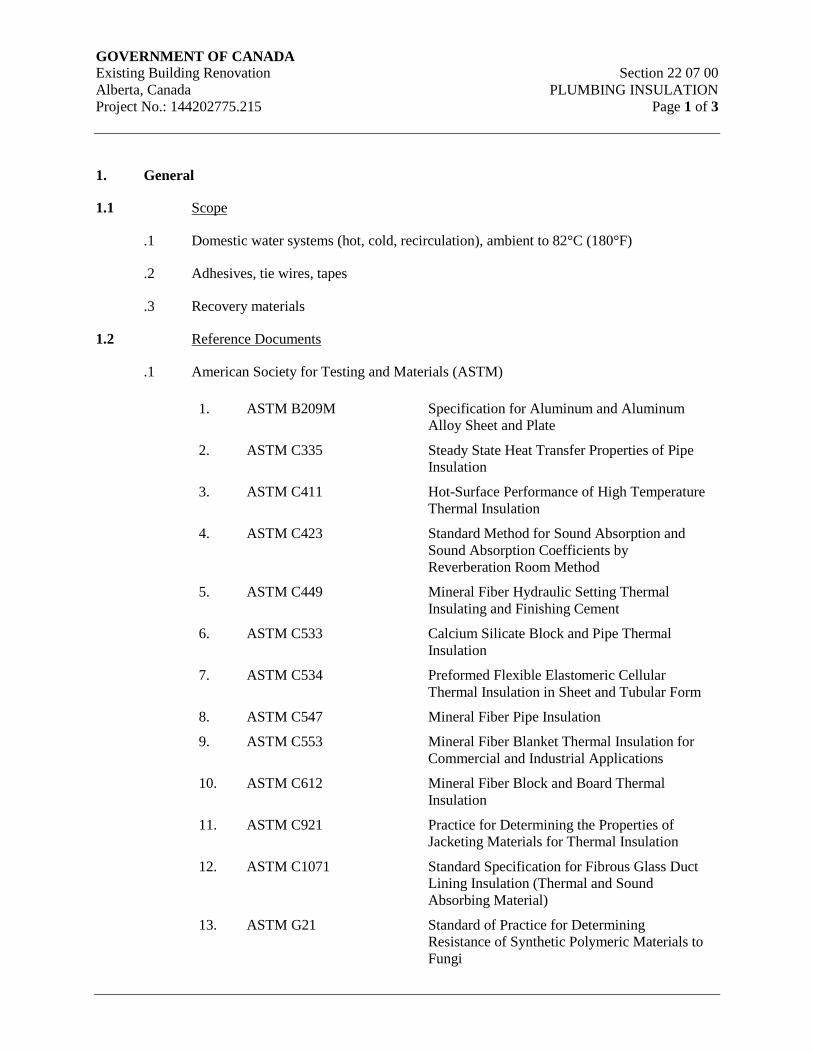
GOVERNMENT OF CANADA Existing Building Renovation Section 22 07 00
Alberta, Canada PLUMBING INSULATION
Project No.: 144202775.215 Page 1 of 3
1. General
1.1 Scope
.1 Domestic water systems (hot, cold, recirculation), ambient to 82°C (180°F)
.2 Adhesives, tie wires, tapes
.3 Recovery materials
1.2 Reference Documents
.1 American Society for Testing and Materials (ASTM)
1. ASTM B209M Specification for Aluminum and Aluminum
Alloy Sheet and Plate
2. ASTM C335 Steady State Heat Transfer Properties of Pipe
Insulation
3. ASTM C411 Hot-Surface Performance of High Temperature
Thermal Insulation
4. ASTM C423 Standard Method for Sound Absorption and
Sound Absorption Coefficients by
Reverberation Room Method
5. ASTM C449 Mineral Fiber Hydraulic Setting Thermal
Insulating and Finishing Cement
6. ASTM C533 Calcium Silicate Block and Pipe Thermal
Insulation
7. ASTM C534 Preformed Flexible Elastomeric Cellular
Thermal Insulation in Sheet and Tubular Form
8. ASTM C547 Mineral Fiber Pipe Insulation
9. ASTM C553 Mineral Fiber Blanket Thermal Insulation for
Commercial and Industrial Applications
10. ASTM C612 Mineral Fiber Block and Board Thermal
Insulation
11. ASTM C921 Practice for Determining the Properties of
Jacketing Materials for Thermal Insulation
12. ASTM C1071 Standard Specification for Fibrous Glass Duct
Lining Insulation (Thermal and Sound
Absorbing Material)
13. ASTM G21 Standard of Practice for Determining
Resistance of Synthetic Polymeric Materials to
Fungi
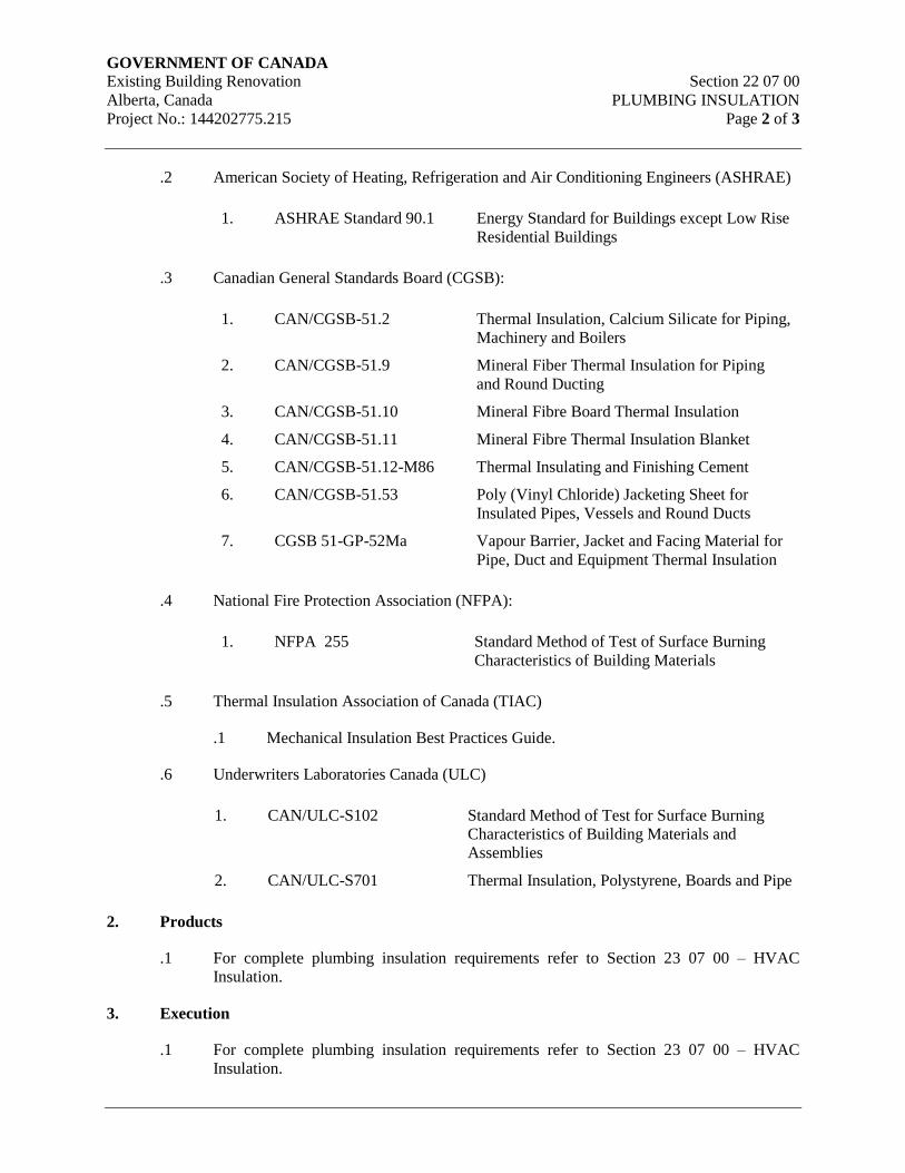
GOVERNMENT OF CANADA Existing Building Renovation Section 22 07 00
Alberta, Canada PLUMBING INSULATION
Project No.: 144202775.215 Page 2 of 3
.2 American Society of Heating, Refrigeration and Air Conditioning Engineers (ASHRAE)
1. ASHRAE Standard 90.1 Energy Standard for Buildings except Low Rise
Residential Buildings
.3 Canadian General Standards Board (CGSB):
1. CAN/CGSB-51.2 Thermal Insulation, Calcium Silicate for Piping,
Machinery and Boilers
2. CAN/CGSB-51.9 Mineral Fiber Thermal Insulation for Piping
and Round Ducting
3. CAN/CGSB-51.10 Mineral Fibre Board Thermal Insulation
4. CAN/CGSB-51.11 Mineral Fibre Thermal Insulation Blanket
5. CAN/CGSB-51.12-M86 Thermal Insulating and Finishing Cement
6. CAN/CGSB-51.53 Poly (Vinyl Chloride) Jacketing Sheet for
Insulated Pipes, Vessels and Round Ducts
7. CGSB 51-GP-52Ma Vapour Barrier, Jacket and Facing Material for
Pipe, Duct and Equipment Thermal Insulation
.4 National Fire Protection Association (NFPA):
1. NFPA 255 Standard Method of Test of Surface Burning
Characteristics of Building Materials
.5 Thermal Insulation Association of Canada (TIAC)
.1 Mechanical Insulation Best Practices Guide.
.6 Underwriters Laboratories Canada (ULC)
1. CAN/ULC-S102 Standard Method of Test for Surface Burning
Characteristics of Building Materials and
Assemblies
2. CAN/ULC-S701 Thermal Insulation, Polystyrene, Boards and Pipe
2. Products
.1 For complete plumbing insulation requirements refer to Section 23 07 00 – HVAC
Insulation.
3. Execution
.1 For complete plumbing insulation requirements refer to Section 23 07 00 – HVAC
Insulation.

GOVERNMENT OF CANADA Existing Building Renovation Section 22 07 00
Alberta, Canada PLUMBING INSULATION
Project No.: 144202775.215 Page 3 of 3
END OF SECTION
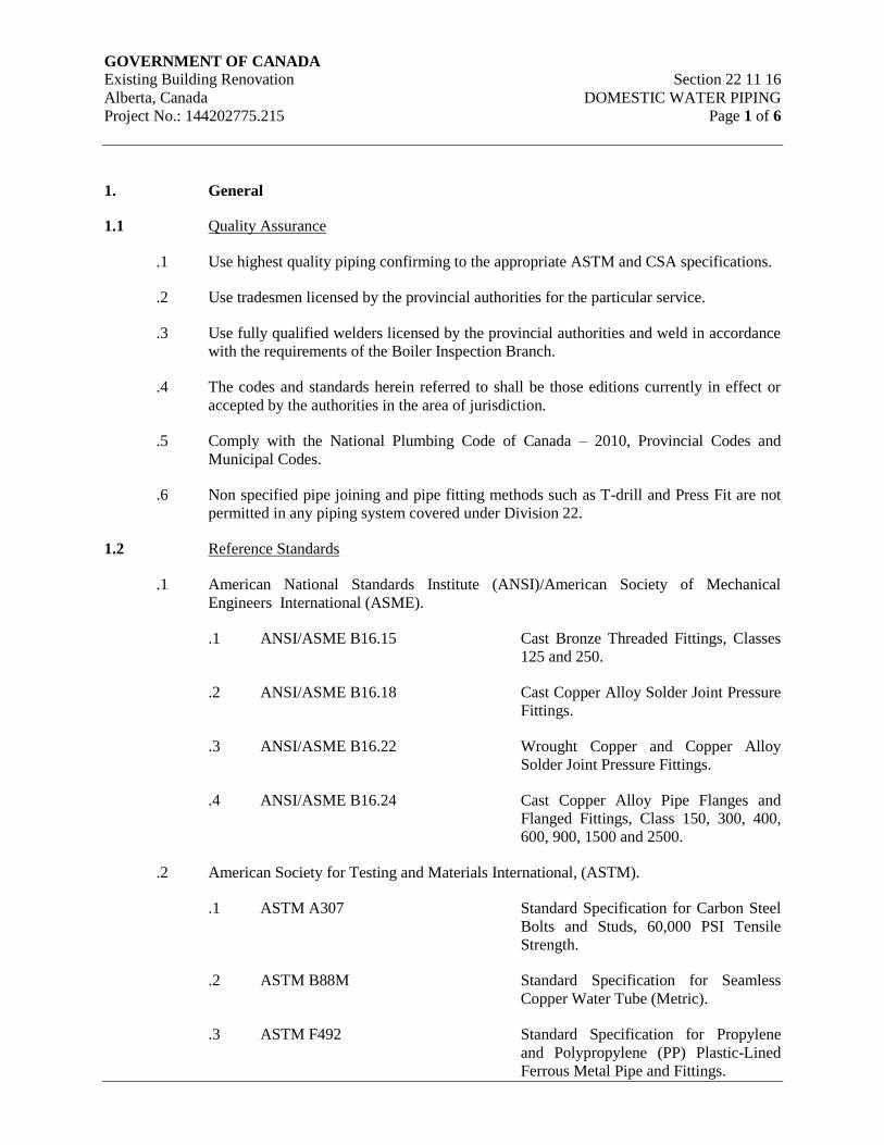
GOVERNMENT OF CANADA Existing Building Renovation Section 22 11 16
Alberta, Canada DOMESTIC WATER PIPING
Project No.: 144202775.215 Page 1 of 6
1. General
1.1 Quality Assurance
.1 Use highest quality piping confirming to the appropriate ASTM and CSA specifications.
.2 Use tradesmen licensed by the provincial authorities for the particular service.
.3 Use fully qualified welders licensed by the provincial authorities and weld in accordance
with the requirements of the Boiler Inspection Branch.
.4 The codes and standards herein referred to shall be those editions currently in effect or
accepted by the authorities in the area of jurisdiction.
.5 Comply with the National Plumbing Code of Canada – 2010, Provincial Codes and
Municipal Codes.
.6 Non specified pipe joining and pipe fitting methods such as T-drill and Press Fit are not
permitted in any piping system covered under Division 22.
1.2 Reference Standards
.1 American National Standards Institute (ANSI)/American Society of Mechanical
Engineers International (ASME).
.1 ANSI/ASME B16.15 Cast Bronze Threaded Fittings, Classes
125 and 250.
.2 ANSI/ASME B16.18 Cast Copper Alloy Solder Joint Pressure
Fittings.
.3 ANSI/ASME B16.22 Wrought Copper and Copper Alloy
Solder Joint Pressure Fittings.
.4 ANSI/ASME B16.24 Cast Copper Alloy Pipe Flanges and
Flanged Fittings, Class 150, 300, 400,
600, 900, 1500 and 2500.
.2 American Society for Testing and Materials International, (ASTM).
.1 ASTM A307 Standard Specification for Carbon Steel
Bolts and Studs, 60,000 PSI Tensile
Strength.
.2 ASTM B88M Standard Specification for Seamless
Copper Water Tube (Metric).
.3 ASTM F492 Standard Specification for Propylene
and Polypropylene (PP) Plastic-Lined
Ferrous Metal Pipe and Fittings.
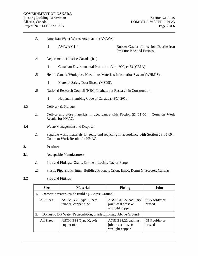
GOVERNMENT OF CANADA Existing Building Renovation Section 22 11 16
Alberta, Canada DOMESTIC WATER PIPING
Project No.: 144202775.215 Page 2 of 6
.3 American Water Works Association (AWWA).
.1 AWWA C111 Rubber-Gasket Joints for Ductile-Iron
Pressure Pipe and Fittings.
.4 Department of Justice Canada (Jus).
.1 Canadian Environmental Protection Act, 1999, c. 33 (CEPA).
.5 Health Canada/Workplace Hazardous Materials Information System (WHMIS).
.1 Material Safety Data Sheets (MSDS).
.6 National Research Council (NRC)/Institute for Research in Construction.
.1 National Plumbing Code of Canada (NPC) 2010
1.3 Delivery & Storage
.1 Deliver and store materials in accordance with Section 23 05 00 – Common Work
Results for HVAC.
1.4 Waste Management and Disposal
.1 Separate waste materials for reuse and recycling in accordance with Section 23 05 00 –
Common Work Results for HVAC.
2. Products
2.1 Acceptable Manufacturers
.1 Pipe and Fittings: Crane, Grinnell, Ladish, Taylor Forge.
.2 Plastic Pipe and Fittings: Building Products Orion, Emco, Domn-X, Scepter, Canplas.
2.2 Pipe and Fittings
Size Material Fitting Joint
1. Domestic Water, Inside Building, Above Ground:
All Sizes ASTM B88 Type L, hard
temper, copper tube
ANSI B16.22 capillary
joint, cast brass or
wrought copper
95-5 solder or
brazed
2. Domestic Hot Water Recirculation, Inside Building, Above Ground:
All Sizes ASTM B88 Type K, soft
copper tube
ANSI B16.22 capillary
joint, cast brass or
wrought copper
95-5 solder or
brazed
GOVERNMENT OF CANADA Existing Building Renovation Section 22 11 16
Alberta, Canada DOMESTIC WATER PIPING
Project No.: 144202775.215 Page 3 of 6
2.3 Unions, Flanges, and Couplings
.1 All other services, size 50mm and under: 1034 kPa malleable iron, bronze to iron ground
joint unions for threaded ferrous piping, all bronze for copper piping. Unions to ANSI
B16.3.
2.4 Solder
.1 Generally, use 95-5 solder for pressure service, 50-50 solder for gravity drainage service.
2.5 Miscellaneous
.1 Use factory fabricated butt weld fittings for welded steel pipes.
.2 Use long radius elbows for steel and cast iron water piping.
3. Execution
3.1 Piping General
.1 Install piping approximately as shown, with all lines being carried parallel to building
walls, as close to the structure as possible, or as detailed on the drawings.
.2 Align and support all piping properly, under no circumstances may any piping load be
transferred to the equipment. Make all equipment connections so as to allow disassembly
of the piping for equipment removal and maintenance.
.3 Install piping to allow for expansion and contraction without unduly stressing pipe or
connected equipment.
.4 Provide clearance for proper installation of insulation and for access to valves, air vents,
drains and unions.
.5 Use only eccentric reducing fittings. Top flat for water.
.6 Do not use direct welded or screwed connections to valves, equipment or other apparatus.
Make all connections with an accessible mechanical connection of a style consistent with
the connecting pipe joints. For grooved pipe system, use rigid couplings to prevent valve
rotation.
.7 Sleeve all pipe passing through partitions, walls and floors.
.8 Provide non-conducting type dielectric connections wherever jointing dissimilar metals.
.9 Ensure no contact between copper and ferrous metal.
.10 Provide drain valves at main shut-off valves, low points of piping and apparatus, and at
the bottom of all risers.
GOVERNMENT OF CANADA Existing Building Renovation Section 22 11 16
Alberta, Canada DOMESTIC WATER PIPING
Project No.: 144202775.215 Page 4 of 6
.11 Keep open ends of pipe free from scale and dirt. Whenever work is suspended during
construction, protect the open ends by using temporary plugs, burlap or other means
approved by the consultant.
.12 Do not run piping carrying liquids over electrical switchboards, elevator controllers or
electrical motor starters. Where this is unavoidable, provide 1.2mm gauge aluminum
pans under piping. Each drip pan shall have a drain piped to discharge over nearest
available open drain. This does not apply in Mechanical Rooms.
.13 Provide for isolation of systems by section.
.14 Make connections to equipment, specialty components, and branch mains after isolation
valves, with unions or flanges.
.15 Use insulating plastic spacers for copper pipe installation in metal studs.
.16 Ensure piping location does not subject piping to frost damage under flow or no-flow
conditions.
3.2 Solder and Brazed Connections
.1 Remove burrs and chips and ream or file the pipe ends out to size or bore. In the case of
soft copper tubing, ensure that reaming restores tubing to full diameter before jointing to
fitting.
.2 Assemble joints without binding. Brazing material or solder shall penetrate fully and fill
the joint completely.
3.3 Route and Grades
.1 Route piping in orderly manner and maintain proper grades. Install to conserve headroom
and interfere as little as possible with use of space. Run exposed piping parallel to walls.
Group piping wherever practical at common elevations. Install concealed pipes close to
the building structure to keep furring to a minimum.
.2 Slope water piping 0.2% and provide hose bibb drains at low points.
.3 Provide air collection chambers with manual air vent at all high points of system.
Collection chambers to be 25mm (1”) dia or line size whichever is greater and 150mm
(6”) high minimum. Square tees may only be used to assist with complete venting and
draining.
3.4 Installation
.1 Water piping shall be complete from service connection to all fixtures, equipment,
outlets, etc. Sizes of pipes shall be as shown or as specified.
.2 Exercise care in the laying of soft copper tubing that it does not bear or is in contact with
rocks and that directional changes are gradual to ensure tubing will not be kinked or
collapsed.

GOVERNMENT OF CANADA Existing Building Renovation Section 22 11 16
Alberta, Canada DOMESTIC WATER PIPING
Project No.: 144202775.215 Page 5 of 6
.3 All brass and copper pipe and tubing shall be free from cuts, dents or other surface
damage at the time of final inspection. Remove damaged pipe or tubing and replace with
new pipe or tubing.
.4 Take branches from water supply mains from the top, bottom, or side, using crossover
fittings where required by structural or operating conditions.
.5 Install piping to allow for expansion and contraction without unduly stressing pipe or
equipment connected.
.6 Provide clearance for proper installation of insulation and for access to valves, air vents,
drains and unions.
3.5 Plumbing Systems and Piped Utility Tests
.1 Refer to Section 23 05 00 – Common Work Results for HVAC for system testing and
startup requirements.
.2 All domestic water piping shall be tested in accordance with the current National
Plumbing Code of Canada, 2010 and under the requirements of the Local Plumbing
Inspection Branch.
.3 If approved, hydrostatic tests may be substituted with air or smoke tests when there is a
danger of freezing.
.4 Test interior domestic water piping system. Completely fill and hydraulically test with a
pressure of at least 1035 kPa (346 ft W.G.) at system low point, maintain the pressure for
four (4) hours after all air has been expelled with all outlets tightly closed. Isolate system
components not designed for this test pressure.
.5 Test site water service from connection to utility water supply to building in the manner
prescribed by the local water supply utility, but no less than the performance described
below:
.1 Hydrostatically test for a period of not less than one (1) hour, at a pressure of the
greater of 1-1/2 times the maximum operating pressure of 1035 kPa (346 ft
W.G.).
.2 During the hydrostatic test, all exposed pipes, fittings, valves, hydrants and joints
will be examined for visible leaks. Repair joints and remove defective
components and then repeat test.
.3 Conduct a leakage test after the hydrostatic test. Subject the pipe to normal
operating pressure for at least a two (2) hour period. The measured leakage shall
not exceed the number of liters per hour as determined by the formula:
L = ND(P)
31735

GOVERNMENT OF CANADA Existing Building Renovation Section 22 11 16
Alberta, Canada DOMESTIC WATER PIPING
Project No.: 144202775.215 Page 6 of 6
Where L is the allowable leakage, N is the number of joints in the length of
pipeline tested, D is the nominal diameter of the pipe in mm and P is the normal
operating pressure in kPa. No leakage is permitted on welded piping.
.6 Test emergency fixtures as per ANSI standard Z358.1 (current edition). Test that the
tempered water discharge temperature is 23.9°C (75°F).
END OF SECTION
GOVERNMENT OF CANADA Existing Building Renovation Section 22 11 19
Alberta, Canada DOMESTIC WATER PIPING SPECIALTIES
Project No.: 144202775.215 Page 1 of 4
1. General
1.1 Scope
.1 Water hammer arrestors
.2 Backflow preventers
.3 Vacuum breakers
.4 Trap primers
1.2 General Requirements
.1 Provide materials, equipment and labor to install plumbing as required by Provincial and
Local Codes as specified herein.
.2 Provide water connections to equipment furnished in other sections of this specification
and by the Owner. Refer to Section 23 05 00 – Common Work Results for HVAC.
.3 Provide and include charges for connections to Municipal and Utility Company services,
including costs to maintain temporary water supply pending acceptable water quality
tests, where applicable.
.4 Every plumbing fixture is to be equipped with separate water line fixture stops at water
connections to fixtures.
1.3 Standard References
.1 American Society for Testing and Materials International (ASTM)
.1 ASTM A126 Specification for Gray Iron Castings for
Valves, Flanges and Pipe Fittings.
.2 ASTM B62 Specification for Composition Bronze or
Ounce Metal Castings.
.2 Canadian Standards Association (CSA International)
.1 CSA-B64 Series Backflow Preventers and Vacuum
Breakers.
.2 CSA-B79 Floor, Area and Shower Drains, and
Cleanouts for Residential Construction.
.3 CSA-B356 Water Pressure Reducing Valves for
Domestic Water Supply Systems.
.3 National Research Council (NRC)/Institute for Research in Construction.
GOVERNMENT OF CANADA Existing Building Renovation Section 22 11 19
Alberta, Canada DOMESTIC WATER PIPING SPECIALTIES
Project No.: 144202775.215 Page 2 of 4
.1 National Plumbing Code of Canada (NPC) 2010
.4 Plumbing and Drainage Institute (PDI)
.1 PDI-WH201 Water Hammer Arresters Standard.
1.4 Delivery & Storage
.1 Deliver and store materials in accordance with Section 23 05 00 – Common Work
Results for HVAC.
1.5 Waste Management and Disposal
.1 Separate waste materials for reuse and recycling in accordance with Section 23 05 00 –
Common Work Results for HVAC.
1.6 Submittals
.1 Provide shop drawings for the equipment noted below. Clearly identify model number
and any options selected.
2. Products
2.1 Acceptable Manufacturers
1. Water Hammer Arrestors : Jay R. Smith, Watts, Zurn.
2. Vacuum Breakers : Febco, Watts.
3. Trap Primers : Jay R. Smith, Watts, Zurn
2.2 Water Hammer Arrestors
.1 Fit water supply to each fixture or group of fixtures with an air chamber. Provide air
chambers same size as supply line or 20mm (¾”) minimum, and minimum 450mm (18”)
long.
.2 Provide stainless steel bellows or piston type water hammer arrestors on water lines
connected to solenoid valves, flush valves and to fixture or group of fixtures complete
with accessible isolation valve. Water hammer arrestors to be Zurn Z-1700 (bellows) or
Z-1705 (piston) or equal.
Standard of Acceptance: Zurn Z-1700 (bellows)
Standard of Acceptance: Zurn Z-1705 (piston)
2.3 Vacuum Breaker Assemblies
.1 Provide pressure type vacuum breaker assembly complete with shut-off valves before and
after check valves and test cocks. Assembly shall consist of one (1) positive sealing
check valve and one (1) atmospheric vent disk with stainless steel or bronze seats
GOVERNMENT OF CANADA Existing Building Renovation Section 22 11 19
Alberta, Canada DOMESTIC WATER PIPING SPECIALTIES
Project No.: 144202775.215 Page 3 of 4
complete with shut-off valves before and after check valves and test cocks. Assembly
shall meet AWWA requirements and CSA B64 standards.
Standard of Acceptance: Watts No. 800M4QT
.2 Provide atmospheric type vacuum breaker assembly complete with shut-off valve before
assembly. Assembly shall consist of one (1) free floating poppet to seal the atmospheric
vent under flow conditions.
Standard of Acceptance: Watts No. 288A
Standard of Acceptance: Watts No. 388ASC (for bottom inlet and outlet)
.3 Provide hose connection type vacuum breaker assembly, consisting of a check valve disc
assembly to be vandal proof and drainable.
Standard of Acceptance: Watts No. 8A
Standard of Acceptance: Watts No. NF8 (use for freezing conditions)
2.4 Trap Seal Primers
.1 For single floor drains the trap primer shall be automatically activated complete with
vacuum breaker; connected to nearest cold water line and piped to traps. Provide access
door for concealed installations.
Standard of Acceptance: Zurn 1022
3. Execution
3.1 Installation
.1 Install approved backflow preventer or vacuum breaker assemblies on water lines where
contamination of domestic water may occur.
.2 Install trap primers on all floor drains.
.3 Double checks can be in horizontal or vertical, depending on manufacturer’s installation
instructions.
.4 Do not run any wet piping through electrical machine rooms or other similar rooms.
.5 Coordinate fixture carrier requirements with architectural features and drawing
requirements.
3.2 Vacuum Breakers
.1 Install vacuum breaker on all hose bibbs and where shown on drawings.
.2 Provide air gaps on all atmospheric drains such as drains from coils, blowdowns, tanks,
equipment, riser drains, and relief valve discharge.

GOVERNMENT OF CANADA Existing Building Renovation Section 22 11 19
Alberta, Canada DOMESTIC WATER PIPING SPECIALTIES
Project No.: 144202775.215 Page 4 of 4
END OF SECTION
GOVERNMENT OF CANADA Existing Building Renovation Section 22 13 16
Alberta, Canada SANITARY WASTE AND VENT PIPING
Project No.: 144202775.215 Page 1 of 5
1. General
1.1 Quality Assurance
.1 Use highest quality piping confirming to the appropriate ASTM and CSA specifications.
.2 Use tradesmen licensed by the provincial authorities for the particular service.
.3 The codes and standards herein referred to shall be those editions currently in effect or
accepted by the authorities in the area of jurisdiction.
.4 Comply with the National Plumbing Code of Canada – 2010, Provincial Codes and
Municipal Codes.
1.2 Reference Standards
.1 American Society for Testing and Materials International, (ASTM)
.1 ASTM B32 Specification for Solder Metal.
.2 ASTM B306 Specification for Copper Drainage Tube
(DWV).
.3 ASTM C564 Specification for Rubber Gaskets for
Cast Iron Soil Pipe and Fittings.
.4 ASTM D2235 Specification for Solvent Cement for
Acrylonitrille-Butadiene-Styrene (ABS)
Plastic Pipe and Fittings.
.5 ASTM D2564 Specifications for Solvent Cements for
Poly(Vinyl-Chloride) (PVC) Plastic
Piping Systems.
.2 Canadian Standards Association (CSA International)
.1 CSA B67 Lead Service Pipe, Waste Pipe, Traps,
Bends and Accessories.
.2 CAN/CSA-B70 Cast Iron Soil Pipe, Fittings and Means
of Joining.
.3 CAN/CSA-B125 Plumbing Fittings.
.4 CSA-Series B1800 Plastic Nonpressure Pipe Compendium.
.5 CSA-B181.2 PVC Drain, Waste and Vent Pipe and
Pipe Fittings.
GOVERNMENT OF CANADA Existing Building Renovation Section 22 13 16
Alberta, Canada SANITARY WASTE AND VENT PIPING
Project No.: 144202775.215 Page 2 of 5
.6 CSA-B182.1 Plastic Drain and Sewer Pipe and Pipe
Fittings.
.3 National Research Council (NRC)
.1 National Plumbing Code of Canada (NPC) 2010
1.3 Delivery & Storage
.1 Deliver and store materials in accordance with Section 23 05 00 – Common Work
Results for HVAC.
1.4 Waste Management and Disposal
.1 Separate waste materials for reuse and recycling in accordance with Section 23 05 00 –
Common Work Results for HVAC.
2. Products
2.1 Acceptable Manufacturers
.1 Pipe and Fittings: Crane, Grinnell, Ladish, Taylor Forge.
.2 Plastic Pipe and Fittings: Building Products Orion, IPEX, Emco, Domn-X, Scepter,
Canplas.
2.2 Pipe and fittings
Size Material Fittings Joint
1. Sanitary, Waste and Vent Piping Above Grade (Inside Building):
65 (2½”) and
smaller
ASTM B306 DWV
grade hard temper
copper tube
ANSI B16.29 cast
brass or wrought
copper
Soldered 50-50
75 (3”) and
larger
CSA.B70,27580 kPa
crushing strength,
cast iron with varnish
asphalt base
Cast iron, CSA
B70, factory
applied corrosion
resistant coating
inside and out
Mechanical joint,
Hub & Spigot
2. Sanitary, Waste and Vent Piping Below Grade (Inside Building):
All sizes CSA.B70, 27580 kPa
crushing strength,
cast iron with varnish
asphalt base
Cast iron, CSA
B70, with a heavy
bituminous coating
Mechanical joint,
Hub & Spigot
150 (6”) and
smaller
ABS-DWV to CSA
B181.1 - 1973
ABS Solvent cement
GOVERNMENT OF CANADA Existing Building Renovation Section 22 13 16
Alberta, Canada SANITARY WASTE AND VENT PIPING
Project No.: 144202775.215 Page 3 of 5
Size Material Fittings Joint
150 (6”) and
smaller
PVC, DWV to CSA
B181.2 - 1973
PVC PVC solvent cement,
solvent weld
2.3 Solder
.1 Generally, use 95-5 solder for pressure service, 50-50 solder for gravity drainage service.
2.4 Couplings
.1 Hubless couplings shall be composed of a stainless steel shield, clamp assembly and
elastomeric sealing sleeves to CSA-B602 and CAN/ULC-S102.
3. Execution
3.1 Piping General
.1 Make joints for plain end pipe with gasket and clamp type mechanical fastener.
.2 Clamp cast iron water pipe at fittings with 20mm (¾”) rods and properly anchor and
support.
.3 Install piping approximately as shown, with all lines being carried parallel to building
walls, as close to the structure as possible, or as detailed on the drawings.
.4 Align and support all piping properly, under no circumstances may any piping load be
transferred to the equipment. Make all equipment connections so as to allow disassembly
of the piping for equipment removal and maintenance.
.5 Install piping to allow for expansion and contraction without unduly stressing pipe or
connected equipment.
.6 Provide clearance for proper installation of insulation and for access to valves, air vents,
drains and unions.
.7 Use only eccentric reducing fittings.
.8 Sleeve all pipe passing through partitions, walls and floors.
.9 Provide non-conducting type dielectric connections wherever jointing dissimilar metals.
.10 Ensure no contact between copper and ferrous metal.
.11 Keep open ends of pipe free from scale and dirt. Whenever work is suspended during
construction, protect the open ends by using temporary plugs, burlap or other means
approved by the consultant.
.12 Ensure piping location does not subject piping to frost damage under flow or no-flow
conditions.
GOVERNMENT OF CANADA Existing Building Renovation Section 22 13 16
Alberta, Canada SANITARY WASTE AND VENT PIPING
Project No.: 144202775.215 Page 4 of 5
.13 Install and support piping so that strain and weight does not bear on cast iron fittings or
apparatus.
.14 Mechanical contractor is to provide pictures of underground services to the mechanical
engineer a minimum of one (1) week prior to the services being backfilled.
.15 Underground piping installed below structural slabs is to be supported by pipe hangers
hung from the structure.
3.2 Solder and Brazed Connections
.1 Remove burrs and chips and ream or file the pipe ends out to size or bore. In the case of
soft copper tubing, ensure that reaming restores tubing to full diameter before jointing to
fitting.
.2 Assemble joints without binding. Brazing material or solder shall penetrate fully and fill
the joint completely.
3.3 Route and Grades
.1 Route piping in orderly manner and maintain proper grades. Install to conserve headroom
and interfere as little as possible with use of space. Run exposed piping parallel to walls.
Group piping wherever practical at common elevations. Install concealed pipes close to
the building structure to keep furring to a minimum.
.2 Grade horizontal drainage and vent piping 2% minimum.
3.4 Installation
.1 Run pipes in straight lines and have a uniform grade between elevations noted. No
branch drain shall have a lesser grade than that indicated for the main drain to which it is
connected. Where elevations are not given, pipes shall have a uniform grade of 6.5mm
per 300mm, except that where such grade on overhead pipes would reduce the headroom
materially, the grade may be reduced to not less than 3.2mm per 300mm, if so directed by
the consultant. All overhead pipes must be kept as close to ceilings as possible, unless
otherwise indicated or noted.
.2 Do not use double hubs, straight crosses, double T’s or double TY’s in any soil or waste
pipe below any fixture. Do not install a branch fitting other than the full Y and an eight
bend on any soil or waste pipe running in a horizontal plane. Quarter bends placed on
their sides shall not be permitted. Do not use inverted joints below any fixture.
3.5 Plumbing Systems and Piped Utility Tests
.1 Refer to Section 22 05 00 – Common Work Results for Plumbing for system testing and
startup requirements.
.2 All drainage piping shall be tested in accordance with the National Plumbing Code of
Canada, 2010 and under the requirements of the Local Plumbing Inspection Branch.

GOVERNMENT OF CANADA Existing Building Renovation Section 22 13 16
Alberta, Canada SANITARY WASTE AND VENT PIPING
Project No.: 144202775.215 Page 5 of 5
.3 If approved, hydrostatic tests may be substituted with air or smoke tests when there is a
danger of freezing.
.4 Test drainage system by filling with water to produce a pressure of 30 kPa (10 ft. W.G.)
minimum and 75 kPa (25 ft. W.G.) maximum. Check for proper grade and obstruction
by ball test.
END OF SECTION

GOVERNMENT OF CANADA Existing Building Renovation Section 22 13 19
Alberta, Canada SANITARY WASTE PIPING SPECIALTIES
Project No.: 144202775.215 Page 1 of 3
1. General
1.1 Scope
.1 Cleanouts
.2 Floor drains
.3 Sediment interceptors
1.2 General Requirements
.1 Provide materials, equipment and labor to install plumbing as required by Provincial and
Local Codes as specified herein.
.2 Provide and include charges for connections to Municipal and Utility Company services.
1.3 Standard References
.1 American Society for Testing and Materials International (ASTM)
.1 ASTM A126 Specification for Gray Iron Castings for
Valves, Flanges and Pipe Fittings.
.2 ASTM B62 Specification for Composition Bronze or
Ounce Metal Castings.
.2 Canadian Standards Association (CSA International)
.1 CSA-B79 Floor, Area and Shower Drains, and
Cleanouts for Residential Construction.
.3 National Research Council (NRC)/Institute for Research in Construction.
.1 National Plumbing Code of Canada (NPC) 2010
1.4 Delivery & Storage
.1 Deliver and store materials in accordance with Section 23 05 00 – Common Work
Results for HVAC.
1.5 Waste Management and Disposal
.1 Separate waste materials for reuse and recycling in accordance with Section 23 05 00 –
Common Work Results for HVAC.
1.6 Submittals
.1 Provide shop drawings for the equipment noted below. Clearly identify model number
and any options selected.
GOVERNMENT OF CANADA Existing Building Renovation Section 22 13 19
Alberta, Canada SANITARY WASTE PIPING SPECIALTIES
Project No.: 144202775.215 Page 2 of 3
2. Products
2.1 Acceptable Manufacturers
1. Cleanouts : Jay R. Smith, Mifab, Zurn, Watts.
2. Floor Drains : Jay R. Smith, Mifab, Zurn, Watts.
3. Sediment Inteceptors : Jay R. Smith, Mifab, Zurn, Watts.
2.2 Cleanouts and Cleanout Access Covers
.1 Supply and install cleanout on all drains at all changes in direction, at the ends of all
horizontal runs, at the base of every stack where drains leave the building; where shown
on the drawings; 7.6m (25 ft) apart in horizontal drainage lines of 50mm (2”) and 65mm
(2-1/2”) nominal diameter; 15.2m (50 ft) apart in horizontal lines of 75mm (3”) or
100mm (4”) nominal diameter and not more than 26m (85 ft) for larger pipe sizes and as
called for in the National Plumbing Code.
.2 All cleanouts shall be full size for pipes up to 100mm (4”) diameter and 100mm (4”) size
of larger pipes. Cleanouts shall be extended to a finished wall or floor.
.3 Provide caulked or threaded type extended to finished floor or wall surface. Ensure
ample clearance at cleanout for rodding of drainage system. The piping shall be extended
beyond the room for cleanout installation. Where cleanouts occur in carpeted areas, they
shall be extended to the finished walls unless the Consultant gives special permission for
them to terminate in the carpeted floor.
.4 Cleanouts for copper pipe shall be cast brass with raised shoulder on plug and gasket.
.5 Cleanouts for cast iron pipe shall be steel plug type.
.6 Covers for cleanouts shall be as follows:
.1 Unfinished areas, such as concrete floors in equipment rooms and flush type
cleanouts in outside areas:
Standard of Acceptance: Zurn ZXN-1612 with cover suitable for heavy
traffic.
.2 Slab on grade finished in ceramic tile; cleanout to be complete with nickel bronze
frame and cover:
Standard of Acceptance: Zurn ZN-1400-Z
.3 Upper floors finished in ceramic tile; cleanout to be complete with nickel bronze
frame and cover:
Standard of Acceptance: Zurn ZN-1400-Z
GOVERNMENT OF CANADA Existing Building Renovation Section 22 13 19
Alberta, Canada SANITARY WASTE PIPING SPECIALTIES
Project No.: 144202775.215 Page 3 of 3
.4 Floors finished in lino or other such thin material; cleanout to be complete with
nickel bronze frame and cover:
Standard of Acceptance: Zurn ZN-1400-TX (square)
Standard of Acceptance: Zurn ZN-1400-X (round)
.7 All barriers for cleanout plugs shall be securely anchored so that they do not rotate when
the plug is being removed.
2.3 Floor Drains
.1 Flow Characteristics: Full open flow unless noted otherwise. Check all construction
details prior to ordering drains and ensure the drains are suitable for the construction.
.2 Refer to Plumbing Fixture Schedule on drawings for floor drain types.
2.4 Sediment Interceptors
.1 Construct sediment interceptor from epoxy coated steel and shall have a gasketed epoxy
coated steel skid-proof cover.
.2 Set interceptors as shown on drawings. Provide extensions for recessed interceptors as
necessary.
.3 Refer to Plumbing Fixture Schedule on drawings for capacities and sizes.
3. Execution
3.1 Installation
.1 Lubricate cleanout plugs with mixture of graphite and linseed oil. Prior to building
turnover, remove cleanout plugs, re-lubricate and re-install using only enough force to
ensure permanent leakproof joint.
.2 Install trap primers on all floor drains. Refer to Section 22 11 19 – Domestic Water
Piping Specialties. Primers shall be installed in an area accessible for easy maintenance.
.3 Plumbing vents shall be located minimum 5m (16’-0”) from air intakes.
.4 Do not run any wet piping through electrical machine rooms or other similar rooms.
.5 Provide dielectric fittings in all dissimilar metal connections.
.6 Coordinate type of floor drains specified with building construction details.
END OF SECTION
GOVERNMENT OF CANADA Existing Building Renovation Section 22 15 13
Alberta, Canada GENERAL SERVICE
Project No.: 144202775.215 COMPRESSED AIR PIPING
Page 1 of 2
1. General
1.1 Quality Assurance
.1 All compressed air piping systems shall be installed to the approval of the Authority
Having Jurisdiction.
2. Products
2.1 Pipe
Service Size Material Fittings Joint
.1 Compressed
Air
50 (2”)
and under
Type ‘L’ hard
copper, ASTM
B88M
Wrought copper
or cast brass
95-5 Solder
2.2 Unions, Flanges, and Couplings
.1 Size 50mm (2”) and under: 1035kPa (150 psi) malleable iron, bronze to iron ground joint
unions for threaded ferrous piping, air tested for gas service, all bronze for copper piping.
Unions to ANSI B16.3.
.2 Unions to be 4137 kPa (600 psi) malleable iron with brass-to-iron ground seat. Unions to
be to ANSI B16.3.
.3 Couplings to be threaded, to ANIS B16.11.
3. Execution
3.1 Preparation
.1 Ream pipes and tubes. Clean off scale and dirt, inside and outside, before assembly.
Remove welding slag or other foreign material from piping.
.2 Provide dielectric type connections wherever jointing dissimilar metals in open systems.
Brass adapters and valves are acceptable.
.3 Use insulating plastic spacers for copper pipe installation in metal studs.
3.2 Route and Grades
.1 Route piping in orderly manner and maintain proper grades. Install to conserve headroom
and interfere as little as possible with use of space. Run exposed piping parallel to walls.
Group piping wherever practical at common elevations. Install concealed pipes close to
the building structure to keep furring to a minimum.
.2 Slope air piping 0.2% and provide valved and capped drains at low points.

GOVERNMENT OF CANADA Existing Building Renovation Section 22 15 13
Alberta, Canada GENERAL SERVICE
Project No.: 144202775.215 COMPRESSED AIR PIPING
Page 2 of 2
3.3 Installation
.1 Assemble joints without binding. Solder shall penetrate fully and fill the joint
completely.
.2 Install unions to permit removal or replacement of equipment.
.3 Make branch connections from top of main.
.4 Install compressed air trap at bottom of each riser and at low points in minas, complete
with hose end drain and valve. Valves must be at readily accessible locations, serviced
from the floor or mezzanine. Distance between drain points to be 30 meters (100 feet)
maximum.
.5 Install piping to allow for expansion and contraction without unduly stressing pipe or
equipment connected.
.6 Provide clearance for access to valves, drains and unions.
.7 Blow out all piping to clean interior thoroughly of all oil and foreign matter.
.8 Testing:
.1 Pressure test for 4 hours minimum to 2068 kPa (300 psi) with outlets closed and
with compressor isolated from system. Pressure drop not to exceed 10 kPa
(1.5 psi)
END OF SECTION
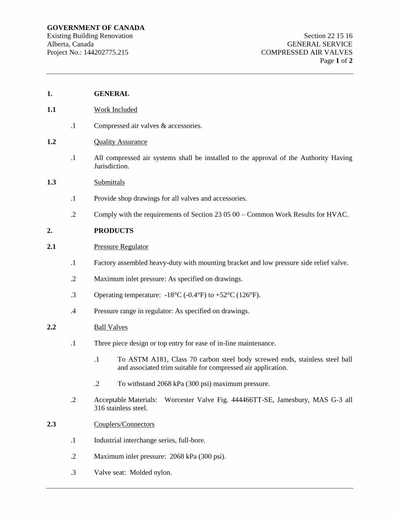
GOVERNMENT OF CANADA Existing Building Renovation Section 22 15 16
Alberta, Canada GENERAL SERVICE
Project No.: 144202775.215 COMPRESSED AIR VALVES
Page 1 of 2
1. GENERAL
1.1 Work Included
.1 Compressed air valves & accessories.
1.2 Quality Assurance
.1 All compressed air systems shall be installed to the approval of the Authority Having
Jurisdiction.
1.3 Submittals
.1 Provide shop drawings for all valves and accessories.
.2 Comply with the requirements of Section 23 05 00 – Common Work Results for HVAC.
2. PRODUCTS
2.1 Pressure Regulator
.1 Factory assembled heavy-duty with mounting bracket and low pressure side relief valve.
.2 Maximum inlet pressure: As specified on drawings.
.3 Operating temperature: -18°C (-0.4°F) to +52°C (126°F).
.4 Pressure range in regulator: As specified on drawings.
2.2 Ball Valves
.1 Three piece design or top entry for ease of in-line maintenance.
.1 To ASTM A181, Class 70 carbon steel body screwed ends, stainless steel ball
and associated trim suitable for compressed air application.
.2 To withstand 2068 kPa (300 psi) maximum pressure.
.2 Acceptable Materials: Worcester Valve Fig. 444466TT-SE, Jamesbury, MAS G-3 all
316 stainless steel.
2.3 Couplers/Connectors
.1 Industrial interchange series, full-bore.
.2 Maximum inlet pressure: 2068 kPa (300 psi).
.3 Valve seat: Molded nylon.
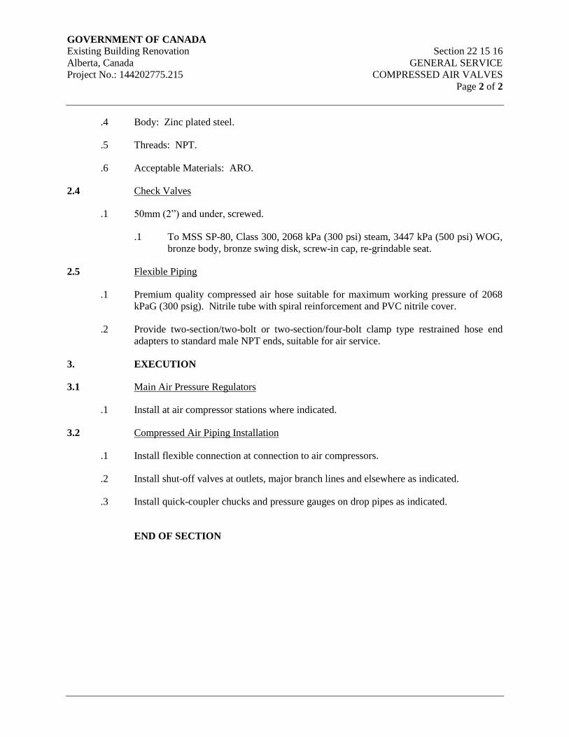
GOVERNMENT OF CANADA Existing Building Renovation Section 22 15 16
Alberta, Canada GENERAL SERVICE
Project No.: 144202775.215 COMPRESSED AIR VALVES
Page 2 of 2
.4 Body: Zinc plated steel.
.5 Threads: NPT.
.6 Acceptable Materials: ARO.
2.4 Check Valves
.1 50mm (2”) and under, screwed.
.1 To MSS SP-80, Class 300, 2068 kPa (300 psi) steam, 3447 kPa (500 psi) WOG,
bronze body, bronze swing disk, screw-in cap, re-grindable seat.
2.5 Flexible Piping
.1 Premium quality compressed air hose suitable for maximum working pressure of 2068
kPaG (300 psig). Nitrile tube with spiral reinforcement and PVC nitrile cover.
.2 Provide two-section/two-bolt or two-section/four-bolt clamp type restrained hose end
adapters to standard male NPT ends, suitable for air service.
3. EXECUTION
3.1 Main Air Pressure Regulators
.1 Install at air compressor stations where indicated.
3.2 Compressed Air Piping Installation
.1 Install flexible connection at connection to air compressors.
.2 Install shut-off valves at outlets, major branch lines and elsewhere as indicated.
.3 Install quick-coupler chucks and pressure gauges on drop pipes as indicated.
END OF SECTION
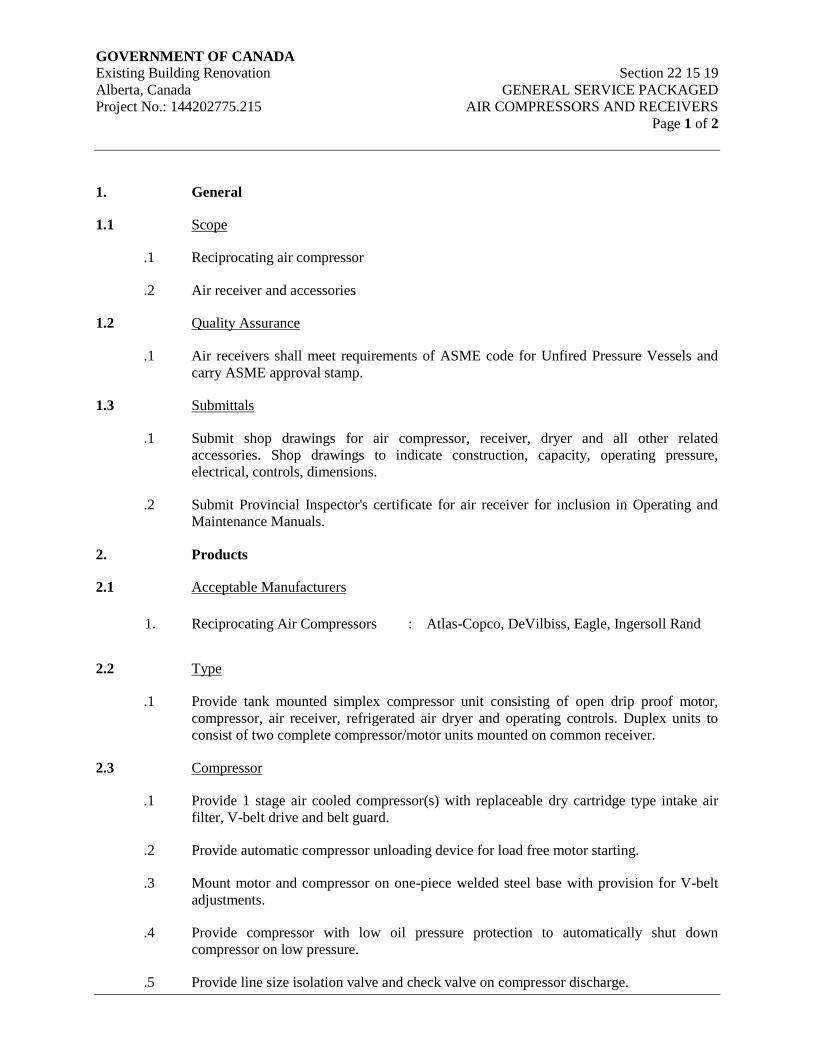
GOVERNMENT OF CANADA Existing Building Renovation Section 22 15 19
Alberta, Canada GENERAL SERVICE PACKAGED
Project No.: 144202775.215 AIR COMPRESSORS AND RECEIVERS
Page 1 of 2
1. General
1.1 Scope
.1 Reciprocating air compressor
.2 Air receiver and accessories
1.2 Quality Assurance
.1 Air receivers shall meet requirements of ASME code for Unfired Pressure Vessels and
carry ASME approval stamp.
1.3 Submittals
.1 Submit shop drawings for air compressor, receiver, dryer and all other related
accessories. Shop drawings to indicate construction, capacity, operating pressure,
electrical, controls, dimensions.
.2 Submit Provincial Inspector's certificate for air receiver for inclusion in Operating and
Maintenance Manuals.
2. Products
2.1 Acceptable Manufacturers
1. Reciprocating Air Compressors : Atlas-Copco, DeVilbiss, Eagle, Ingersoll Rand
2.2 Type
.1 Provide tank mounted simplex compressor unit consisting of open drip proof motor,
compressor, air receiver, refrigerated air dryer and operating controls. Duplex units to
consist of two complete compressor/motor units mounted on common receiver.
2.3 Compressor
.1 Provide 1 stage air cooled compressor(s) with replaceable dry cartridge type intake air
filter, V-belt drive and belt guard.
.2 Provide automatic compressor unloading device for load free motor starting.
.3 Mount motor and compressor on one-piece welded steel base with provision for V-belt
adjustments.
.4 Provide compressor with low oil pressure protection to automatically shut down
compressor on low pressure.
.5 Provide line size isolation valve and check valve on compressor discharge.
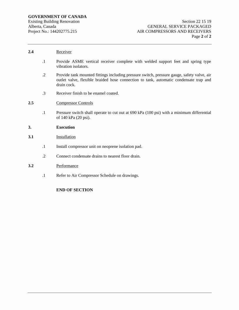
GOVERNMENT OF CANADA Existing Building Renovation Section 22 15 19
Alberta, Canada GENERAL SERVICE PACKAGED
Project No.: 144202775.215 AIR COMPRESSORS AND RECEIVERS
Page 2 of 2
2.4 Receiver
.1 Provide ASME vertical receiver complete with welded support feet and spring type
vibration isolators.
.2 Provide tank mounted fittings including pressure switch, pressure gauge, safety valve, air
outlet valve, flexible braided hose connection to tank, automatic condensate trap and
drain cock.
.3 Receiver finish to be enamel coated.
2.5 Compressor Controls
.1 Pressure switch shall operate to cut out at 690 kPa (100 psi) with a minimum differential
of 140 kPa (20 psi).
3. Execution
3.1 Installation
.1 Install compressor unit on neoprene isolation pad.
.2 Connect condensate drains to nearest floor drain.
3.2 Performance
.1 Refer to Air Compressor Schedule on drawings.
END OF SECTION
GOVERNMENT OF CANADA Existing Building Renovation Section 22 45 00
Alberta, Canada EMERGENCY PLUMBING FIXTURES
Project No.: 144202775.215 Page 1 of 2
1. General
1.1 Scope
.1 Emergency eye/face wash units
.2 Emergency mixing valves
1.2 General Requirements
.1 Provide new fixtures, CSA approved, free from flaws and blemishes with finished
surfaces clear, smooth and bright.
.2 Provide CSA approved plumbing fittings. Visible parts of fixture brass and accessories
shall be heavily chrome plated.
.3 Fixtures shall be product of one manufacturer. Fittings of same type shall be product of
one manufacturer.
.4 Protect fixtures against use and damage during construction.
1.3 Job Conditions
.1 Check millwork shop drawings. Confirm location and size of fixtures and openings
before rough-in and installation. Advise consultant of discrepancies prior to ordering
fixtures or trim.
1.4 Submittals
.1 Submit shop drawings for review.
2. Products
2.1 Acceptable Manufacturers
1. Emergency Eye/Face Wash Units : Bradley, Encon, Haws
2. Emergency Mixing Valves : Bradley, Haws, Leonard
2.2 Emergency Eye / Face Wash Units
.1 Refer to Plumbing Fixture Schedule for emergency eye/face wash unit types.
2.3 Emergency Mixing Valves
.1 Refer to Plumbing Fixture Schedule for emergency mixing valve types.

GOVERNMENT OF CANADA Existing Building Renovation Section 22 45 00
Alberta, Canada EMERGENCY PLUMBING FIXTURES
Project No.: 144202775.215 Page 2 of 2
3. Execution
3.1 Installation
.1 Install each fixture with its own trap, easily removable for servicing and cleaning. At
completion thoroughly clean plumbing fixtures and equipment.
.2 Provide chrome plated rigid or flexible supplies to fixtures with screw driver stops,
reducers and escutcheons.
.3 Provide pressure reducing valves on water lines to fixtures which are not rated for the
system operating pressures.
.4 All trim and plumbing fixtures shall be located as per the Architectural Details.
END OF SECTION
GOVERNMENT OF CANADA Existing Building Renovation Section 23 01 30.51
Alberta, Canada HVAC AIR DISTRIBUTION
Project No.: 144202775.215 SYSTEM CLEANING
Page 1 of 4
1. General
1.1 Scope
.1 This contractor shall be responsible for and ensure that all ductwork is internally clean
when handed over to the Owner. This responsibility includes the entire system, from
outdoor air intakes to air terminals and from air terminal to relief outlets. It includes all
ductwork, lined and unlined, all plenums and all equipment within or connected to ducts
and plenums.
.2 The surfaces shall be considered clean when all foreign materials capable of particulating
and visible to the naked eye are removed.
.3 The Contractor shall initiate quality control measures during the fabrication and
installation of all ductwork to clean/keep clean all ductwork, so that ductwork cleaning
may not be required at the completion of the work. Consultant shall review cleanliness of
ductwork, and at the sole discretion and direction of the Consultant, the ductwork
cleaning requirements of this section may be required, reduced or eliminated. However,
if the ductwork does require cleaning, it shall be done as per the requirements of this
section, and shall be at no additional cost to the Owner.
1.2 Definitions
.1 Clean: No visible particulates or deposition in air systems after vacuum techniques have
been completed.
.2 Air Systems: Includes central equipment; supply, return, exhaust fans, coils, dampers,
turning vanes, grilles, diffusers, high, medium and low pressure ductwork (supply, return
and exhaust) that is associated with an air handling system.
1.3 Quality Assurance
.1 Ductwork cleaning firms shall be specialists in this field.
.2 The HVAC system cleaning sub-trade shall be a certified member of the National Air
Duct Cleaners Association (NADCA) or equivalent.
.3 The Owner may hire an independent agency to review duct cleaning procedures prior to
starting work and perform spot checks to confirm that duct system cleaning has been
effectively executed.
1.4 Related Work Specified in Other Sections
.1 Common Work Results for HVAC Section 23 05 00
.2 Metal Ducts Section 23 31 13
.3 Air Duct Accessories Section 23 33 13

GOVERNMENT OF CANADA Existing Building Renovation Section 23 01 30.51
Alberta, Canada HVAC AIR DISTRIBUTION
Project No.: 144202775.215 SYSTEM CLEANING
Page 2 of 4
1.5 Waste Management and Disposal
.1 Separate waste materials for reuse and recycling in accordance with Section 23 05 00 –
Common Work Results for HVAC.
1.6 Approved Agencies
.1 Contractor to submit proposed agency for Consultant and Owner approval.
1.7 Submittals
.1 Submit certification of NADCA membership (or equivalent).
.2 Submit list of five (5) recent projects of similar magnitude.
.3 Submit the name of the superintendent-in-charge of the work and list his project
experience.
.4 Submit an outline of the work scope for each ductwork system for review prior to starting
work, including lighting strategy and procedures, cleaning procedures, equipment,
materials, and schedule.
.5 Submit a certificate of completion for each ductwork system that cleaning has been
completed as defined in the specifications.
2. Products
Not Applicable
3. Execution
3.1 Preparation
.1 All ductwork shall be wiped clean prior to installation.
.2 Oil film on sheet metal shall be removed before shipment to Work Site. Finished
ductwork shall be stood vertically for 72 hours to allow oil remnants to drains as
indicated by SMACNA. Ducts shall be inspected for oil remnants prior to shipping to
site.
.3 Close all dampers immediately following installation thus checking the operation and
retarding movement of contaminants through the system.
.4 Seal all openings at the end of each day and at such other time as site conditions dictate.
.5 Floor openings to be capped with sheet metal or floor grilles plus 0.15 mm (6 mils) thick
poly sheet.
.6 Other openings to be covered with 0.15 mm (6 mils) thick poly sheet taped so as to be air
tight.
GOVERNMENT OF CANADA Existing Building Renovation Section 23 01 30.51
Alberta, Canada HVAC AIR DISTRIBUTION
Project No.: 144202775.215 SYSTEM CLEANING
Page 3 of 4
3.2 Installing Access Doors
.1 Provide and locate access doors and install as follows:
.1 At 12.0m (36 ft) intervals in vertical ducts.
.2 Horizontal ducts at intervals of 6m (18 ft).
.3 At the base of all duct risers.
.4 Both sides of turning vanes in all ducts.
.5 At each fire damper location.
.6 At each side of all coils except where an access is provided.
.7 At all locations of internally duct mounted equipment or devices including
balancing dampers, automatic dampers, damper motors, duct mounted smoke
detectors and heat detectors, and controls, except where access is provided.
.8 Where required to facilitate duct cleaning.
3.3 Cleaning
.1 On completion of the duct and plenum installation and prior to the installation of air
terminals and prior to balancing of the air systems, but not until the areas are substantially
clean (floors have been swept and vacuumed) and all "dirty" construction has been
completed, employ an approved Cleaning Agency to vacuum clean the following:
.1 All air handling units.
.2 All plenums.
.3 All supply and return air ducts.
.4 All exhaust air ducts.
.2 All components within each system shall be thoroughly cleaned and shall include but not
be limited to the following: coils, fans and motors, silencers, air terminals and mixing
boxes / air terminal boxes.
.3 When connecting to existing supply ductwork, clean existing supply ducts upstream from
connection back to the filters. Clean existing supply ductwork downstream from new
connections to outlets.
.4 Cleaning shall generally be by high capacity power vacuum. High-pressure compressed
air, wire brushing and/or non-toxic solvent cleaning shall be used where dirt or scale
cannot be removed otherwise.
.5 Install temporary filters as follows:
GOVERNMENT OF CANADA Existing Building Renovation Section 23 01 30.51
Alberta, Canada HVAC AIR DISTRIBUTION
Project No.: 144202775.215 SYSTEM CLEANING
Page 4 of 4
.1 Behind all grilles and diffusers.
.2 In front of all duct coils.
.3 At inlet of all terminal high velocity units to protect pitot openings.
.6 The Cleaning Contractor shall be responsible for removing and replacing filter media.
This contractor will remove the temporary filters and replace with new after cleaning the
systems.
.7 The Cleaning Contractor shall mark balancing damper positions before cleaning and
return them to their original position when cleaning is completed unless the system is still
to be balanced.
.8 Reinstall any grilles, registers and diffusers, which may have been removed for cleaning
purposes.
.9 After the duct systems have been cleaned they shall be resealed if they are not being
used. Provide filter media on the return air terminals, in a ducted return system, if the
return air fans are run after cleaning has been completed. Where the ceiling is being used
as a return air plenum, provide filter media on the return air opening at the shaft.
.10 The Cleaning Agency shall perform a full inspection of the duct interior. Utilizing a fibre
optic borescope with dedicated light source, inspect interior ductwork surfaces, and
ductwork accessories including terminal units, mixing boxes / air valves, ductwork liners,
duct-mounted coils, filters, dampers, humidifiers and all other appurtenances within the
ductwork system.
.11 Spot checks will be made by the Consultant during the cleaning process to verify that the
required standard is being met. When substantial performance is claimed, final spot
checks will be made to verify that the ducts are clean. Make available for the use of the
Consultant a fibre optic borescope with dedicated light source. If any ducts are found to
be unclean, then they shall be recleaned.
.12 Ducts serving very clean areas served with 85% NBS or HEPA filters shall be reviewed
by the Consultant utilizing the equivalent of a white glove wipe technique.
.13 Submit a report from the cleaning agency that certifies all specified air systems have been
cleaned
3.4 Inspection
.1 Ductwork cleanliness will be inspected using a periscope built of 75mm (3”) diameter
tube, mirrors and flashlight.
.2 Ductwork found to be dirty shall be re-cleaned at contractor’s expense.
.3 Ductwork cleanliness shall be inspected by the mechanical engineer.
END OF SECTION
GOVERNMENT OF CANADA Existing Building Renovation Section 23 05 00
Alberta, Canada COMMON WORK RESULTS FOR HVAC
Project No.: 144202775.215 Page 1 of 35
1. General
1.1 Intent
.1 Work in Division 22 and 23 will include all drawings and all sections of the
specifications that form the Contract Documents, including all addenda, and including
Division 00 and Division 01, whether defined in Division 22 and 23 or elsewhere, or
whether defined in mechanical drawings or elsewhere.
.2 Provide complete, fully tested and operational mechanical systems to meet requirements
described herein and in complete accord with applicable codes and ordinances. Include
all costs to obtain all permits and to pay for all fees and charges, including inspection
charges by the authorities that issue the permits. Coordinate all related inspections.
Permits, fees and inspections including:
.1 Ventilation
.2 Building HVAC
.3 Building plumbing
.3 Contract documents consisting of the specifications and drawings, are generally
diagrammatic and approximately to scale unless detailed otherwise. They establish
scope, material and installation quality and are not detailed installation instructions.
.4 Review Contract Documents and notify the Consultant of issues or conflict that require
clarification prior to submitting tender. Failure by the Contractor to secure clarification
does not relieve the Contractor to comply with the intent of the design and/or the
Contract Document.
1.2 Related Requirements
.1 Refer to and comply with the following sections:
.1 General Requirements Division 01
.2 Submittal Procedures Section 01 33 00
.3 Delegated Design Submittals Section 01 33 50
.4 Quality Control Section 01 45 00
.5 Temporary Utilities Section 01 51 00
.6 Closeout Procedures Section 01 77 00
.7 Closeout Submittals Section 01 78 00
.8 Demonstration and Training Section 01 79 00
.9 Commissioning Section 01 91 00
.10 General Commissioning (Cx) Requirements Section 01 91 13
.11 Building Management Manual Section 01 91 51
GOVERNMENT OF CANADA Existing Building Renovation Section 23 05 00
Alberta, Canada COMMON WORK RESULTS FOR HVAC
Project No.: 144202775.215 Page 2 of 35
1.3 Related Work Specified in Other Sections
.1 Bidding Requirements and General Conditions of Contract Division 01
.2 Electric Motor Power Characteristics Division 26
1.4 Codes, Regulations, Permits, Fees and Inspections
.1 Conform to the latest edition and supplements of the following for all materials and
installations:
.1 National Building Code (NBC) 2010
.2 Alberta Building Code (ABC) 2014, as amended by local bylaws and Provincial
Statutes.
.3 National Fire Protection Association.
.4 Codes, Standards, Bylaws, Statutes and Manufacturer’s Association
Specifications or instructions mentioned in Division 22 and 23 sections, refer to
latest revisions thereof at time of calling of bids, unless specifically designated
otherwise.
.5 In no instance shall the standard established by the drawings and specifications
be reduced by code or otherwise.
.6 Where conflict or discrepancies between Codes, Standards, Bylaws, Statutes,
Specifications, Drawings, etc., exist, the most stringent requirement shall apply.
.7 Furnish all notices, obtain all necessary permits related to Division 22 and 23
work.
1.5 Installation Requirements
.1 Provide labor, material and tools required to install, test and place into operation, a
complete mechanical system. Provide additional material for modifications required to
correct minor job confliction.
.2 Install material and equipment generally in locations and routes shown, close to building
structure with minimum interference with other services or free space. Remove and
replace improperly installed equipment as determined by the Engineer. Field verify all
dimensions, clearances, maintenance clearances, equipment handing requirements, invert
elevations, and other similar measurements prior to any fabrication and installation.
Notify the Consultant of any discrepancies that require resolution.
.3 Confirm invert elevations and locations of connection to utilities before any excavation
work is started.
.4 Install piping and ductwork only in concealed spaces, unless otherwise approved.

GOVERNMENT OF CANADA Existing Building Renovation Section 23 05 00
Alberta, Canada COMMON WORK RESULTS FOR HVAC
Project No.: 144202775.215 Page 3 of 35
.5 Remove and replace improperly installed mechanical work, or work that requires
modifications due to coordination issues or conflicts.
.6 Review architectural drawings and confirm that plumbing fixtures defined on
Architectural Drawings are consistent with plumbing fixtures defined on mechanical
drawings. Mechanical work shall include supply and installation for all fixtures defined
in the contract documents.
.7 Refer to Architectural Drawings and Structural Drawings for sections, details, dimensions
and information such as fire separations, expansion joints, roof construction, wall
construction that has impact on the mechanical installation.
.8 Examine contract documents prepared by all disciplines and confirm that work can be
installed as defined. No allowance will be made for changes unless the consultant has
been notified in writing prior to tender close.
.9 Follow manufacturer’s recommended installation details and procedures for equipment,
supplemented by details given herein and on plans subject to approval of the consultant.
.10 Locate distribution systems, access doors, equipment and materials for maximum usable
space to satisfaction of consultant.
.11 Install equipment in a manner to facilitate maintenance and ease of repair or replacement.
Provide for adequate access and sufficient clearances.
.12 Equipment used shall not exceed space limitations in any dimension. Replace any
equipment or apparatus which does not meet this Specification at no cost. Assume full
responsibility for the expense of redesign and adjustment to other parts of the building
when proposing the use of acceptable equal or alternate equipment. It is the contractor’s
responsibility to confirm all quantities. Dimensions, performance and accessories
required for all equipment, including matching “standard” and operational accessories
between “equal” and “acceptable” products/suppliers/manufacturers.
.13 Prepare dimensioned drawings showing sleeving, recesses, furring and openings to
coordinate mechanical work with other trades.
.14 Prepare dimensioned drawings for congested areas such as mechanical rooms, shafts,
corridors and spaces that require special attention to complete the installation.
1.6 Equipment Connections
.1 Connect to equipment specified in other Sections and to equipment supplied and installed
by other Contractors or by the Owner. Refer to below and Division 11 for owner supplied
equipment and equipment furnished by other divisions.
.2 Provide rough-in for and make all connections to equipment supplied by Owner or other
trades for this work, including:
.3 Refer to and comply with the following sections:
GOVERNMENT OF CANADA Existing Building Renovation Section 23 05 00
Alberta, Canada COMMON WORK RESULTS FOR HVAC
Project No.: 144202775.215 Page 4 of 35
.1 Plumbing Insulation Section 22 07 00
.2 Domestic Water Piping Section 22 11 16
.3 Domestic Water Piping Specialties Section 22 11 19
.4 Sanitary Waste and Vent Piping Section 22 13 16
.5 Identification for HVAC Piping and Equipment Section 23 05 53
.6 Testing, Adjusting and Balancing for HVAC Section 23 05 93
.7 HVAC Insulation Section 23 07 00
.8 Controls Section 23 09 Series
.9 Metal Ducts Section 23 31 13
.10 Air Duct Accessories Section 23 33 00
.4 Uncrate equipment, assemble, move into place and install. After installation is complete;
start-up and test the equipment.
.5 Make all piping (water, gas, etc.) connections to all the owner and General Contractor
supplied equipment. Include all valves, vents, unions, flanges and traps.
.6 Prior to commencing installation of rough-in for the equipment, coordinate with the final
reviewed equipment shop drawings and with the manufacturer. Revise rough-in as
necessary to meet requirements of actual equipment purchased.
.7 Arrange ducting and piping connections to allow for equipment removal.
.8 All equipment provided by others, which require mechanical connections, shall become
the responsibility of the Division 23 contractor with respect to mechanical connections
only.
1.7 Provisions for Maintenance
.1 Install piping in racks with clearance in between pipes equal to the pipe diameter. Where
piping is stacked, provide a minimum 300mm (12”) clearance in between stacks.
.2 Install maintainable components such as valves, motors, traps, air vents, dampers, filters,
and coils in a manner to facilitate proper access for maintenance.
.3 Install major equipment components such as pumps, fans, dry coolers, chillers at floor
level unless indicated otherwise. Install piping connections with isolating valves located
to allow component removal with minimal system drainage.
.4 Locate flanges/unions to allow equipment removal without interruption to piping work.
.5 Allow adequate space for removal of equipment and components from the mechanical
room space.
.6 Install “Pete’s Plugs” gauges and metering equipment in readily accessible and visual
locations.
GOVERNMENT OF CANADA Existing Building Renovation Section 23 05 00
Alberta, Canada COMMON WORK RESULTS FOR HVAC
Project No.: 144202775.215 Page 5 of 35
.7 Provide extensions to grease cups, lubrication fittings for bearings, etc. to outside of fan
cabinets.
.8 Provide maintenance platforms, ladders, safety rails to Occupational Health and Safety
Standards to accommodate equipment and components not easily accessed from the floor.
.9 Provide lifting lugs attached to the building structure above motors and equipment that
weight in excess of 50 kg (110 lb).
.10 Allow minimum clearance in front of electrical components, such as motor control
centers, starters, VFDs, control panels in accordance with applicable codes.
1.8 Warranty
.1 Comply with warranty requirements defined in Division 01.
.2 Furnish a written guarantee stating that all work executed in this contract will be free
from defective workmanship and materials for a period of one (1) year from the date of
substantial performance of work. The Contractor shall repair and replace any work
which fails or becomes defective during the term of the guarantee/warranty, providing the
operating and maintenance instructions have been complied with. The period of
guarantee specified shall not, in any way, supplant any other guarantees of a longer
period provided by Manufacturers or as called for in the project documents.
1.9 Owner Requirements During Warranty
.1 Unless specified otherwise the Owner shall be responsible for all routine maintenance
requirements as required in the manufacturer’s instructions.
.2 The Owner shall be responsible for supplying replaceable components such as filters and
belts during the warranty period.
1.10 Materials
.1 Materials and equipment installed shall be new, full weight and of quality specified. Use
same brand or manufacturer and model for each specific application.
.2 Each major component of equipment shall bear manufacturer's name, address, catalog
and serial number in a conspicuous place.
.3 Provide statically and dynamically balanced rotating equipment for minimum vibration
and low operating noise levels. Provide balancing certificates if requested by the
consultant.
.4 Replace materials or workmanship below specified quality and relocate work wrongly
placed to satisfaction of the Engineer and at no cost to the Owner.
.5 Install materials and equipment in a quality manner providing good workmanship by
competent tradesmen. At the request of the consultant, provide certificates proving
competency of specialists employed. Certificates shall be from recognized, related
GOVERNMENT OF CANADA Existing Building Renovation Section 23 05 00
Alberta, Canada COMMON WORK RESULTS FOR HVAC
Project No.: 144202775.215 Page 6 of 35
governing associations. The owner and his representatives reserve the right to terminate
any specific person’s employment on this project for failure to prove adequate
qualifications and/or workmanship.
.6 If shop drawings are rejected technically after 3 submissions, the Contractor at no
additional expense to the Owner shall revert the specified product and manufacturer for
this project.
1.11 Availability of Equipment and Materials
.1 Make known in writing to the Engineer ten (10) days prior to the tender closing date any
materials specified that are required to complete the work which are not currently
available or will not be available for use as called for herein. Failing to do so, it will be
assumed that the most expensive alternate has been included in the tender price.
.2 If requested after contract award, provide within 24 hours a list of equipment and
manufacturers to be used on this project. This list shall not be deviated from unless
delivery, performance, or dimension issues require a change to be reviewed by the
Consultant.
1.12 Alternate Materials and Equipment
.1 Comply with the requirements of Division 01.
.2 The price submitted for this contract shall be based on the use of materials and equipment
as specified or as contained within the acceptable equivalent manufacturers listed in each
section.
.3 Requests for approval for tendering purposes of equivalent materials or equipment shall
be submitted in duplicate, to the Engineer no later than ten (10) working days prior to the
closing date of tender for mechanical trade, complete with all applicable technical data,
including performance curves and physical details. Approval of requests shall only be
given by addendum and consistent with all requirements defined in Division 01.
.4 The Contractor shall, in his quotation, indicate the degree of approval obtained from the
Engineer. In the event that the product has been approved as an "Alternate Only", this
shall be stated in the quotation and the difference from the base bid price indicated.
.5 Approved equivalents and/or alternatives to specified products shall be equal in
performance and materials to the specified product in every respect, operate as intended,
meet the space, capacity, and noise requirements outlined. . Equipment which is not
equal will be replaced with the specified equipment at no cost to the Owner.
.6 The Contractor shall be fully responsible for all costs for work or materials required by
the trades or other contractors to accommodate use of other than specified materials or
equipment.
.7 Manufacturers/suppliers which are noted in individual sections as “Acceptable
Manufacturers” are automatically approved for bidding and are not required to follow the
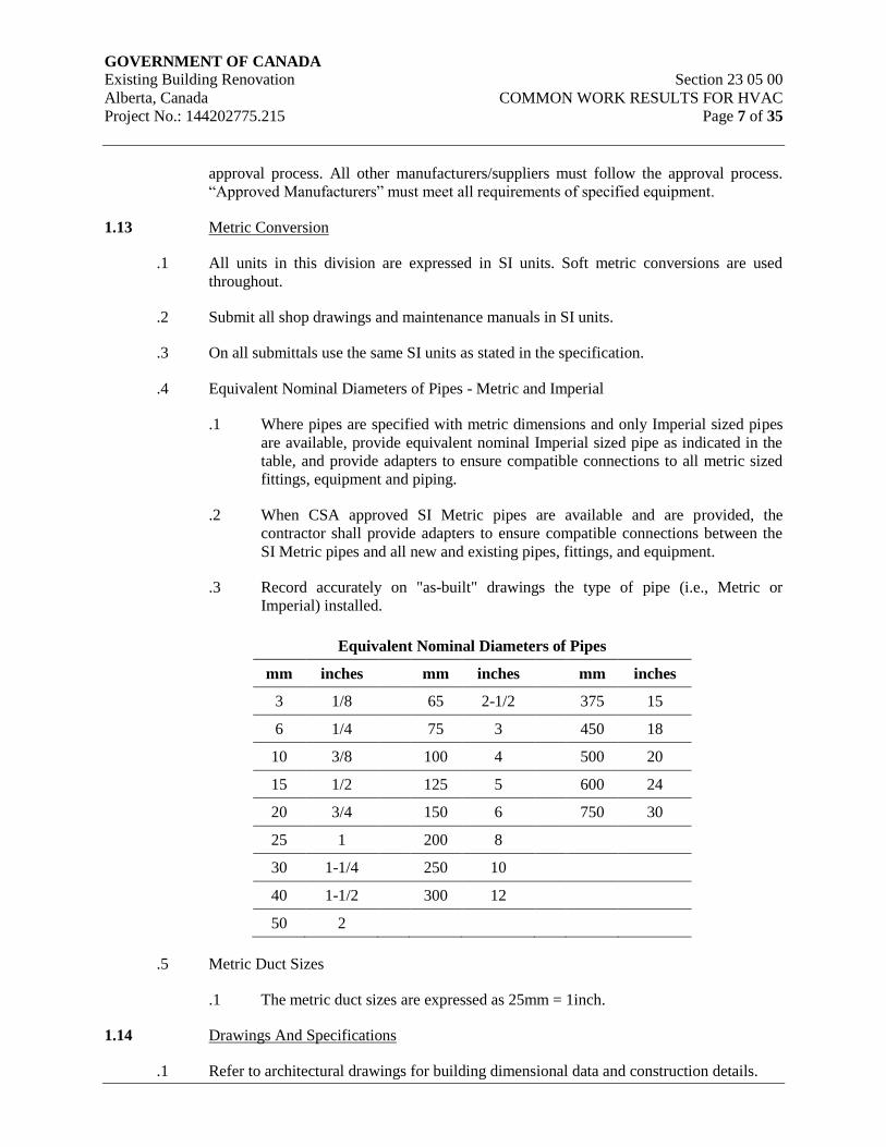
GOVERNMENT OF CANADA Existing Building Renovation Section 23 05 00
Alberta, Canada COMMON WORK RESULTS FOR HVAC
Project No.: 144202775.215 Page 7 of 35
approval process. All other manufacturers/suppliers must follow the approval process.
“Approved Manufacturers” must meet all requirements of specified equipment.
1.13 Metric Conversion
.1 All units in this division are expressed in SI units. Soft metric conversions are used
throughout.
.2 Submit all shop drawings and maintenance manuals in SI units.
.3 On all submittals use the same SI units as stated in the specification.
.4 Equivalent Nominal Diameters of Pipes - Metric and Imperial
.1 Where pipes are specified with metric dimensions and only Imperial sized pipes
are available, provide equivalent nominal Imperial sized pipe as indicated in the
table, and provide adapters to ensure compatible connections to all metric sized
fittings, equipment and piping.
.2 When CSA approved SI Metric pipes are available and are provided, the
contractor shall provide adapters to ensure compatible connections between the
SI Metric pipes and all new and existing pipes, fittings, and equipment.
.3 Record accurately on "as-built" drawings the type of pipe (i.e., Metric or
Imperial) installed.
Equivalent Nominal Diameters of Pipes
mm inches mm inches mm inches
3 1/8 65 2-1/2 375 15
6 1/4 75 3 450 18
10 3/8 100 4 500 20
15 1/2 125 5 600 24
20 3/4 150 6 750 30
25 1 200 8
30 1-1/4 250 10
40 1-1/2 300 12
50 2
.5 Metric Duct Sizes
.1 The metric duct sizes are expressed as 25mm = 1inch.
1.14 Drawings And Specifications
.1 Refer to architectural drawings for building dimensional data and construction details.

GOVERNMENT OF CANADA Existing Building Renovation Section 23 05 00
Alberta, Canada COMMON WORK RESULTS FOR HVAC
Project No.: 144202775.215 Page 8 of 35
.2 Drawings and specifications are complementary each to the other, and what is called for
by one shall be binding as if called for by both. Any item omitted from one but which is
mentioned or reasonably implied in the other shall be considered as properly and
sufficiently specified.
.3 Should any discrepancy appear between drawings and specifications which leaves the
Contractor in doubt as to the true intent and meaning of the plans and specifications,
obtain a ruling from the Engineer in writing or by Addendum, before submitting tender.
If this is not done, it will be assumed that the most expensive alternate has been included.
.4 Where errors or discrepancies appear in catalogue numbers, provide the material in
accordance with the system requirements and to the standard of the specifications.
.5 Prior to construction start, examine all contract documents, including all drawings and
specifications, and work of other trades to ensure that work can be satisfactorily carried
out without changes to building.
.6 The scope of work in this division shall include all work defined in the Contract
Documents, including work which may exceed the minimum requirements of codes and
standards that are referenced in the Contract Documents.
1.15 Examination Of Site
.1 Before submitting tender, visit and examine the site and note all characteristics and
features affecting the work. Report discrepancies to the Engineer seven (7) days prior to
tender closing. No allowances will be made for any difficulties encountered or any
expenses incurred because of any conditions of the site or item existing, thereon, which
are visible or known to exist at the time of tender. Failure to advise Engineer of
discrepancies will assume contractor accepts documents as presented without potential of
additional costs.
1.16 Equipment Delivery, Storage and Cleanup
.1 Arrange, and coordinate, storage space with the General Contractor. Materials and
equipment shall be stored in a safe, dry location and shall be protected against weather,
damage and theft.
.2 Materials to be delivered to site in original factory packaging with manufacturer’s
labeling including name and address.
.3 Protect equipment and materials in storage on site during and after installation until final
acceptance. Leave factory covers in place. Take special precautions to prevent entry of
foreign material into working parts of piping and duct systems.
.4 Protect equipment with polyethylene covers and crates.
.5 Operate, drain and flush out bearings and refill with new change of oil, before final
acceptance.

GOVERNMENT OF CANADA Existing Building Renovation Section 23 05 00
Alberta, Canada COMMON WORK RESULTS FOR HVAC
Project No.: 144202775.215 Page 9 of 35
.6 Thoroughly clean piping, ducts and equipment of dirt, cuttings and other foreign
substances.
.7 Protect bearings and shafts during installation. Grease shafts and sheaves to prevent
corrosion. Supply and install necessary extended nipples for lubrication purposes.
.8 Ensure that existing equipment to be turned over to the Owner or reused is carefully
dismantled and not damaged or lost. Do not reuse existing materials and equipment
unless specifically indicated.
.9 Existing equipment that is to remain in place, and be reused, is to be protected from
physical damage including freezing.
1.17 Waste Management and Disposal
.1 Separate and recycle waste materials in accordance with Section 01 52 00 – Construction
Facilities.
.2 Do not dispose of unused paint material into sewer system, into streams, lakes, onto
ground or in other locations where it will pose health or environmental hazard.
1.18 Coordination of Work
.1 Cooperate and coordinate with other trades on the project. Phase work in sequence with
the General Contractor.
.2 Make reference to electrical, mechanical, structural and architectural drawings when
setting out work. Consult with respective Divisions in setting out locations for ductwork,
equipment, and piping, so that conflicts are avoided and symmetrical even spacing is
maintained. Provide coordination drawings showing the work of all trades and
contractors involved, in areas of potential conflict or congestion, as requested by
Engineer at no additional cost.
.3 Where dimensional details are required, work with the applicable architectural and
structural drawings.
.4 Full size and detailed drawings shall take precedence over scale measurements from
drawings.
.5 Prepare and submit drawings showing sleeving, recesses, and formed work in concrete.
.6 Prepare and submit drawings for all shafts, duct openings, roof openings and similar
requirements.
.7 Coordinate with the Construction Manager and Electrical Trade all requirements for
electrical services to mechanical components and equipment. Motor voltages will be
defined in Division 26.
GOVERNMENT OF CANADA Existing Building Renovation Section 23 05 00
Alberta, Canada COMMON WORK RESULTS FOR HVAC
Project No.: 144202775.215 Page 10 of 35
.8 Using shop drawing data, prepare a comprehensive list to define all specific electrical
requirements needed by the Division 22 and 23 work to complete the installation.
Coordinate with Electrical Trade.
.9 Prepare and submit drawings to the Construction Manager and structural Consultant
defining mechanical system support loads and support details. Include definition of pipe
and/or loads on structural elements and anchor arrangements.
1.19 Coordination with Division 26 (Electrical) Work
.1 Provide motors or mechanical equipment with voltage and phase characteristics as
defined in Division 26.
.2 Comply with the requirements in Section 23 05 13 – Common Motor Requirements for
HVAC Equipment.
.3 Prior to ordering any motor driven mechanical equipment, meet with the electrical trade
and confirm all electrical interface requirements with mechanical components.
.4 Division 22 and 23 (Mechanical) Trade shall:
.1 Submit a list of all motor specifications and electrical connections to mechanical
equipment, outlets, components, panels and point source requirements. Maintain
list up-to-date and make available for site review.
.2 Include final motor list in O&M Manuals.
.3 Supply and install all low voltage (24 V) control devices, temperature control
systems including direct digital central systems defined in Section 23 09 (Series),
Controls.
.4 Supply and set in place all variable frequency drives that are defined in Section
23 05 04, including start-up and commission.
.5 Supply and install 110 V wiring interface with control devices on packaged
equipment, such as liquid level controllers and multi-speed controllers.
.6 Supply and install all low and live voltage wiring associated with automatic
control systems defined in Sections 23 09 (Series), Controls.
.7 Provide CSA labeling on all mechanical equipment with electrical components.
.8 Provide all on-site interconnecting wiring for connecting loose electrical
components supplied with mechanical equipment.
.5 Division 26 (Electrical) Trade will:
.1 Supply and install all electrical components which are required, but not part of
Division 22 and 23 supplied packaged equipment.
GOVERNMENT OF CANADA Existing Building Renovation Section 23 05 00
Alberta, Canada COMMON WORK RESULTS FOR HVAC
Project No.: 144202775.215 Page 11 of 35
.2 Provide wiring interface from distribution equipment to variable frequency drives
(VFDs) and from VFDs to motors.
.3 Extend power wiring from electrical centers to packaged equipment that contains
electrical components.
.6 Refer to Division 26.
1.20 Cutting and Patching
.1 Provide inserts, holes and sleeves, cutting and fitting required for mechanical work.
Relocate improperly located holes and sleeves.
.2 Provide inserts or drill for expansion bolts, hanger rods, brackets, and supports.
.3 Obtain written approval from Engineer before drilling, coring, cutting or burning
structural members. Ensure post tensioned or pre-stressed strands are located accurately
and avoid with an adequate margin of safety.
.4 Cutting practices shall be limited to neat openings created through recognized drilling or
coring practices.
.5 Use only National Building Code approved and rated process and materials for filling of
voids. All processes and materials are subject to the approval of the Fire Commissioner.
Maintain integrity of fire separation.
.6 Patch and make good building where damaged from equipment installation, improperly
located holes etc. Work to be performed by the trade or contractor responsible for that
type of work.
1.21 Temporary Heat
.1 Refer to Section 01 50 00 – Temporary Facilities and Controls.
.2 The building systems shall not be utilized for temporary heat. The contractor may
provide a proposed temporary heat agreement to the Owner for review. However, the
agreement may or may not be accepted, and as a minimum, the following requirements
would have to be met:
.1 The agreement shall include payment schedule for utilities, spare parts listing and
confirmation of warranty.
.2 Thoroughly clean and overhaul permanent equipment used during the
construction period, and replace worn or damaged parts before final inspection at
the sole discretion of the Consultant.
.3 Use of permanent systems for temporary heat shall not modify terms of warranty.
Equipment Manufacturers shall certify that equipment is in "new" condition at
start of warranty period.
GOVERNMENT OF CANADA Existing Building Renovation Section 23 05 00
Alberta, Canada COMMON WORK RESULTS FOR HVAC
Project No.: 144202775.215 Page 12 of 35
.4 Operate heating systems under conditions which ensure no temporary or
permanent damage. No water systems shall operate without proper water
treatment or blow-down. Operate fans at proper resistance with filters installed.
Change filters at regular intervals. Operate with proper safety devices and
controls installed and fully operational. Operate systems only with treated water
as specified.
.5 Air systems may not be used for temporary heating.
.6 Radiant panels may not be used for temporary heating.
.7 When permanent systems are used for temporary heat, provide alarm indicating
system failure. Connect alarm to independent alarm company monitoring
system.
.8 Where pumps are used for temporary heating, replace mechanical seals,
regardless of condition, with new mechanical seals, prior to Total Performance.
.9 Avoid thermal shock to heating system during planning, construction and
operation of temporary heating system.
1.22 Temporary or Trial Usage
.1 Temporary or trial usage requested by the Owner of mechanical equipment supplied
under contract shall not represent acceptance. Operate and maintain all equipment and
systems during trial usage.
.2 Repair or otherwise rectify damage caused by defective materials or workmanship during
temporary or trial usage.
.3 For all ventilation systems, the operation of the system shall be pre-tested by running the
units in their designed maximum fresh air, maximum exhaust air mode once all
distribution ductwork is installed. Inspect filters bi-monthly; change filters if pressure
drop exceeds manufacturer’s recommended operating limit.
1.23 Welding
.1 Use fully qualified welders licensed by the provincial authorities.
.2 For field welding, comply with the procedures of CSA W117.2-M87 “Code for Welding
and Cutting (Requirements for Welding Operators)”.
.3 Welding materials, fabrication standards and labour qualifications must conform to
ANSI/ASME B31.1, ANSI B16.25, ASME Section IX, and the Provincial Board of
Labour Regulations.
.4 Use pressure welders for work on systems containing pressure in excess of 103.4 kPa (15
psig).
.5 Weld in accordance with the requirements of the Provincial Boiler Inspection Branch.
GOVERNMENT OF CANADA Existing Building Renovation Section 23 05 00
Alberta, Canada COMMON WORK RESULTS FOR HVAC
Project No.: 144202775.215 Page 13 of 35
.6 Submit a statement describing welding procedures proposed for the review of the
consultant before commencing work.
.7 Before proceeding with the welded joining on the entire piping system, prepare not more
than ten sample joints for the on-site review by the consultant. The consultant may
request the cutting out of one or more welding joints for close visual examination or x-
ray test. Once the consultant has reviewed the samples, the remaining pipe welding joints
shall be to the standard accepted.
.8 Welded joints shall be free of defects including: elongated slab, isolated slag, porosity,
incomplete penetration, lack of fusion, burn-through, cracks, arc burn, internal concavity,
hollow beads, internal undercuts, and external undercuts.
1.24 Weld Tests
.1 Unless otherwise stated, the quality and interpretation of the radiography performed
under this specification shall conform to CSA Standard Z183, Oil Piping and Z184, Gas
Piping ANSI ASME B31.1 Pressure Piping, B31.3 Refinery Piping and UW51, UW52
Pressure Vessel Codes and all related standards.
.2 All welded joints on piping, regardless of service, but including as a minimum, natural
gas, heating, chilled water and condenser water, low and high pressure steam and
condensate shall be subjected to radiographic inspection with costs borne under the
mechanical construction contract.
.3 Equivalency of weld quality testing may be granted to the contractor on the following
basis at the consultan’ts discretion:
.1 The contractor submits, to the consultant, and obtains approval of a corporate
quality control procedures manual for welding practices.
.2 5% of welds, as a minimum, shall be radiographed on all welded services.
.3 A minimum of two (2) welds shall be radiographed on all services where there
are fewer than twenty (20) welds on the service.
.4 If defects are recorded which, in the opinion of the consultant, are serious, the
consultant may request further radiograph testing of welds to a maximum of
100% of all welded joints at his discretion. The contractor shall bear all related
costs of these extra testing procedures as an acknowledgement of maintenance of
project quality requirements.
.4 A senior radiographer with Canadian Government Standard Board Level 2 qualifications
shall be in the field supervising the radiographic operations under contract.
.5 Prior to beginning work, the following requirements shall be fulfilled:
.1 The radiographic contractor shall supply the consultant with written evidence of
each radiographer’s certification in accordance with “Welds and Weldments”
CGSB 48-G04, latest edition.
GOVERNMENT OF CANADA Existing Building Renovation Section 23 05 00
Alberta, Canada COMMON WORK RESULTS FOR HVAC
Project No.: 144202775.215 Page 14 of 35
.2 The radiographer shall be required to satisfactorily make two (2) qualification
radiographs, which will include exposing and processing the radiographs and
interpreting the radiographs in accordance with applicable code. One (1) copy of
the qualification radiograph shall be kept by the consultant and shall be used as a
standard against which the quality of production radiographs can be checked.
.6 The radiographer shall be responsible for the protection and personal monitoring of every
man working with or near radiation in accordance with the regulations of the Department
of Health and Welfare, Radiation Protection Division. When crank-out type Isotope
camera is used, the area affected by radiation shall be surveyed and limits of hazard
posted.
.7 Submit all certified test reports to the consultant.
1.25 Testing of Soldered Copper Joints
.1 The Engineer, at any time, may select up to five (5) sample soldered copper joints from
installed pipe for review. Samples provided shall be split longitudinally for visual review.
.2 If the submitted samples do not pass a visual inspection to the satisfaction of the
Engineer, the contractor shall arrange and pay for radiographic testing of the samples to
verify quality of workmanship.
.3 Rejection of a sample will require re-test of adjacent joints at the contractor's expense.
.4 Failure of more than 75% of the above removed samples will necessitate removal and
replacement of all joints completed up to the time of test, at contractor’s expense.
1.26 Stray Currents
.1 All wet lines shall be tested for stray currents at total contract performance.
.2 Isolate and correct stray currents to minimize electrolytic action potential.
1.27 Shop Drawings
.1 Submit shop drawings and product data in accordance with Division 1 to consultant for
approval prior to ordering material. Shop drawings are to be submitted electronically
(PDF) and electronic copies will be provided in return with consultant comments and
review stamp. Identify materials and equipment by manufacturer, trade name, and model
number. Include copies of applicable brochure or catalogue material. Space must be left
on the shop drawing to accommodate the Engineers review stamp. Where equipment is
identified by name or number on the drawings or specification, clearly mark each shop
drawing with the identical name and/or number.
.2 Prior to submission to the Engineer, the Contractor shall review all shop drawings. By
this review, the Contractor certifies that he has determined and verified the following:
.1 Measurements are verified with field installation space requirements.

GOVERNMENT OF CANADA Existing Building Renovation Section 23 05 00
Alberta, Canada COMMON WORK RESULTS FOR HVAC
Project No.: 144202775.215 Page 15 of 35
.2 “Handing” of equipment for access and maintenance is correct.
.3 Access for maintenance requirements is defined.
.4 Field connections for wiring, controls, piping and ductwork connections are
defined.
.5 Electrical service connections and characteristics are defined.
.6 Work required by other trades is defined.
.7 Vendor’s catalogue numbers are correct and consistent with the system
performance criteria.
.8 Shop drawings meet all requirements of the contract documents.
.3 The Contractor's review of each shop drawing shall be indicated by stamp, date and
signature of a responsible person.
.4 Identify materials and equipment by manufacturer, trade name, and model number.
Include copies of applicable brochure or catalogue material. Do not assume applicable
catalogues are available in the Engineers office. Maintenance and operating manuals are
not suitable submittal material. Where equipment is identified by name or number on the
drawings or specification, clearly mark each shop drawing with the identical name and/or
number.
.5 Clearly mark each sheet of submittal material (using arrows, underlining, or circling) to
show differences from what is specified, particularly sizes, types, model numbers, rating,
capacities, and options actually being proposed. Cross out non-applicable material.
Specifically note on the submittal specified features such as special tank linings, pump
seals, materials or painting.
.6 The shop drawings shall be complete with detailed wiring schematics, clearly showing
the external electrical connections for power, control and communication. If generic
wiring schematics are provided, they shall be marked up with the terminations and wiring
requirements that are applicable and available only to this project. If wiring requirements
and details are shown for optional equipment and/or devices, the optional equipment
and/or devices shall be provided as part of the project.
.7 Where optional devices, equipment or features are indicated on the data sheets, the
options shall be included as part of the project unless specifically marked up as not being
provided for the project.
.8 Include dimensional and technical data sufficient to check if equipment meets
requirements. Include wiring, piping, service connection data and motor sizes.
.9 Submittals shall be made in BOTH metric and English units.
.10 Installed materials and equipment shall meet specified requirements regardless of
whether or not shop drawings are reviewed by the Engineer.
GOVERNMENT OF CANADA Existing Building Renovation Section 23 05 00
Alberta, Canada COMMON WORK RESULTS FOR HVAC
Project No.: 144202775.215 Page 16 of 35
.11 The shop drawing review by the Engineer will provide the following certification: "This
review by Stantec is for general conformance with the design concept of Stantec’s design
of the Mechanical component(s) only and does not mean that Stantec has verified or
approves the shop drawings(s). The contractor remains solely responsible for the shop
drawings(s) and this review by Stantec does not relieve the Contractor of the Contractor’s
responsibility for errors or omissions in the shop drawings(s) or for meeting all
requirements of the contract documents. This review does not mean that Stantec approve
the detailed design inherent in the shop drawing, responsibility for which shall remain
with the Contractor submitting same, nor does this review mean that Stantec accepts any
deviation of the shop drawings(s) from the contract document. The Contractor is
responsible for confirming all dimensions and correlating them at the job site, for all
construction means, methods and techniques, and for coordination of construction work
of all trades, including coordination of all shop drawings.”
1.28 Record Drawings
.1 Comply with Division 01:
.1 Closeout Procedures Section 01 77 00
.2 Closeout Submittals Section 01 78 00
.2 The contractor shall keep, on site, available to the Engineer at all times and particularly
for each regularly scheduled site meeting, a complete set of prints, edge bound, that are to
be updated daily showing any and all deviations and changes from the Contract
Drawings. This set of drawings is to be used only for this purpose, and must not be used
as the daily general reference set. Make record drawings available for reference and
inspection at all times.
.3 Provide record drawings which identify location of smoke and fire dampers, major
control lines, access doors, tagged valves, and actual room names or numbers. As well,
deviations that are to be recorded shall include, in general, items that are significant or
are hidden from view and items of major importance to future operations and
maintenance, and to future alterations and additions including cleanouts and isolation
valves.
.4 Include on drawings, all addenda and construction contract changes.
.5 Identify each drawing in lower right-hand corner in letters at least 12mm high as follows:
“RECORD DRAWINGS: THIS DRAWING HAS BEEN REVISED TO SHOW
MECHANICAL SYSTEMS AS INSTALLED”, signature of contractor and date.
.6 The cost of producing and plotting the AutoCAD record drawings shall be included in the
tender price. Periodic checks will be carried out to verify that the record drawings are
being kept up to date.
.7 At substantial completion, transfer all deviations, including those called up by addenda,
revisions, clarifications, shop drawings, and change orders, to AutoCAD 2010 files.
Drafting quality layers, symbols, etc. shall be identical to original drawings. Prior to
substantial performance, turn over a CD containing AutoCAD 2010 drawing files and
one (1) complete set of hardcopy record drawings.
GOVERNMENT OF CANADA Existing Building Renovation Section 23 05 00
Alberta, Canada COMMON WORK RESULTS FOR HVAC
Project No.: 144202775.215 Page 17 of 35
.8 Each “record” drawing shall bear the Contractor’s identification, the date of record and
the notation “We hereby certify that these drawings represent the “Work Record of
Construction”. The Contractor’s signature and company seal shall be placed below that
notation.
.9 Enter dimensions from building line to all buried services, including coordinates of
manholes, catch basins, tanks, outside shut-off valves, and other similar elements.
.10 Service connections to water and sewer lines entering a building shall be recorded as to
horizontal dimension from a convenient building element with suitable depth elevations
relating to main floor level and sea level datum.
.11 Sewer and water lines which are placed beneath floor slabs shall be located such that
each point of entry, change in direction, and irregularity is located by dimension from
column grid lines on the record drawings. Depth below slabs shall be given.
1.29 HVAC Systems Testing and Startup
.1 Conduct system startup and testing of systems.
.2 Quality Assurances
.1 Test equipment and material where required by specification or authority having
jurisdiction to demonstrate its proper and safe operation.
.2 Test procedures in accordance with applicable portions of ASME, ASHRAE,
SMACNA and other recognized test codes.
.3 Perform tests on site to the satisfaction of the Engineer. Tests are to be witnessed
by the Consultant and the authorities having jurisdiction. Attendance at tests shall
be at the discretion of the Consultant.
.4 Piping or equipment shall not be concealed or covered until installation is
inspected and approved by the Engineer. Provide written notice to the Engineer
at least three (3) days in advance of tests or concealing of piping.
.5 Coordinate with engineer at start of the project, those tests that will require
witnessing by the Engineer.
.6 Submit sample test certificate forms for review two (2) weeks prior to any testing
on site.
.7 Should a test fail, make repairs and retest until the results are satisfactory to the
Consultant and authority having jurisdiction.
.3 Liability
.1 Take charge of plant during tests, assume responsibility for damages in the event
of injury to personnel, building or equipment and bear costs for liability, repairs
and restoration in this connection.

GOVERNMENT OF CANADA Existing Building Renovation Section 23 05 00
Alberta, Canada COMMON WORK RESULTS FOR HVAC
Project No.: 144202775.215 Page 18 of 35
.4 Submittals
.1 Obtain certificates of approval and acceptance, complying with rules and
regulations from authorities having jurisdiction. Submit copies to be included in
Operating and Maintenance Manuals.
.2 Perform tests as specified. Include test certificates in Operating and Maintenance
Manuals. Itemize each test as to the time performed and personnel responsible.
Submit written report to the consultant within 48 hours after the tests have
occurred.
.5 Execution
.1 Provide equipment, materials and labor for tests and pay expenses. Use test
instruments from approved laboratory or manufacturer and furnish certificate
showing degree of accuracy and date of calibration. Install permanent gauges
and thermometers used for tests just prior to tests to avoid possible changes in
calibration.
.2 Carry out tests for 8 hour period and maintain pressure with no appreciable
pressure drop. Where leakage occurs, repair and re-test and pay necessary costs
for re-witnessing.
.3 During heating and cooling, steam and condensate piping system tests, check
linear expansion at elbows, U-bends, expansion joints and offsets, for proper
clearance. Restrain manufactured expansion joints during hydrostatic tests in
accordance with manufacturer’s recommendations.
.4 When using water as test medium for system not regularly using water, evacuate
and dehydrate the piping and certify the lines are dry following tests. Use agency
specializing in this type of work.
.5 Should tests indicate defective work or variance with specified requirements,
make changes immediately to correct the defects. Correct leaks by remaking
joints in screwed fittings, cutting out and rewelding welded joints, remaking
joints in copper lines. Do not caulk.
.6 Conduct all tests as work is completed and conditions permit, or on portions of
systems as directed by consultant.
.7 Visually check joints during tests for leakage of water test media or in systems
with air or nitrogen tests check joints with soap bubble test.
1.30 HVAC Equipment Testing and Startup
.1 Conduct performance testing of equipment and arrange for manufacturer’s startup of
equipment.
.2 Quality Assurance

GOVERNMENT OF CANADA Existing Building Renovation Section 23 05 00
Alberta, Canada COMMON WORK RESULTS FOR HVAC
Project No.: 144202775.215 Page 19 of 35
.1 Use factory trained representatives and submit manufacturer's check sheets for
starting all systems and equipment.
.2 Prior to starting, testing, balancing, adjusting, and cleaning processes, verify with
Engineer any tests required to be witnessed. Provide sufficient notice to
Engineer prior to commencement of procedures.
.3 Engineer shall be allowed to witness any testing, adjusting, starting, balancing,
and cleaning procedures.
.4 Assume all costs associated with starting and testing, including the supply of
testing or cleaning medium.
.5 Prior to starting equipment or systems, secure and review manufacturer's
installation, operation, and starting instructions. Read in conjunction with
procedures defined herein.
.6 Use manufacturer's or supplier's starting personnel where required to ensure
integrity of manufacturer's warranty.
.7 Compare installations to published manufacturer's data and record discrepancies.
Items potentially detrimental to equipment performance shall be corrected prior
to equipment starting.
.8 Some processes involved in starting procedures defined in this section may be
duplications of authorities verification. To facilitate expedient completion of
project, arrange for authorities to assist or witness these procedures.
.9 All starting, testing, and procedures shall be in accordance with applicable
portions of ASME, ASHRAE, AABC, CSA, NFPA, SMACNA, ASTM, ASPE
and as required and outlined in these specifications.
.10 Personnel involved in starting, testing, balancing and adjusting procedures shall
be experienced in the design and operation of mechanical equipment and systems
being checked and shall be able to interpret results of the readings and tests.
.11 Assume all liabilities associated with starting, testing and balancing procedures.
1.31 Demonstration and Owner’s Instruction for HVAC Systems
.1 Arrange for demonstration of HVAC equipment and systems operations.
.2 Arrange for instruction seminars for Owner’s personnel.
.3 Comply with the requirements of Section 01 79 00 – Demonstration and Training.
.4 Quality Assurance
.1 The mechanical contractor shall arrange for sub-trades and manufacturer’s
representatives to be available for demonstrations and seminars.

GOVERNMENT OF CANADA Existing Building Renovation Section 23 05 00
Alberta, Canada COMMON WORK RESULTS FOR HVAC
Project No.: 144202775.215 Page 20 of 35
1.32 Operation and Maintenance Manuals
.1 Secure and assemble all necessary literature describing the operation and maintenance of
all equipment provided. Complete and transmit documentation for review to Engineer at
project milestones.
.2 Quality Assurance
.1 Work specified shall be performed by an Independent Agency specializing in this
type of work.
.3 Approved Agencies
.1 The contractor is to submit a proposed agency for Consultant and Owner
approval.
1.33 Certificate of Substantial Performance
.1 Comply with Division 01:
.1 Cleaning Section 01 74 11
.2 Closeout Procedures Section 01 77 00
.3 Closeout Submittals Section 01 78 00
.4 Demonstration and Training Section 01 79 00
.5 Commissioning Section 01 91 00
.6 Commissioning (Cx) Plan Section 01 91 31
.7 Building Management Manual (BMM) Section 01 91 51
.2 In addition to the requirements of Division 00 and Division 01, and prior to application
for a "Certificate of Substantial Performance" of the work, the contractor shall certify the
following in writing to the Consultant:
.1 The systems are installed and suitable for operation for the purpose intended.
.2 Plumbing, heating, and ventilation systems are capable of operation with safety
devices and alarm controls functional and automatic controls in operation and the
Owners personnel have had their initial training programs.
.3 All equipment within mechanical rooms is installed.
.4 All thermal and acoustic insulation is installed.
.5 All static pressure tests are complete.
.6 All access doors are suitably located, and equipment easily accessible.
.7 All piping is installed, painted and clearly identified complete with flow arrows.
GOVERNMENT OF CANADA Existing Building Renovation Section 23 05 00
Alberta, Canada COMMON WORK RESULTS FOR HVAC
Project No.: 144202775.215 Page 21 of 35
.8 Systems are chemically cleaned, flushed, and water treatment initiated.
.9 Temporary filters are installed and fan plenums cleaned.
.10 All equipment is checked for operation, alignment amperage draw and rotation.
.11 Rough balance of air and water systems is completed and the reports have been
submitted for review.
.12 All equipment is lubricated as per manufacturer's data.
.13 All valves are tagged and all equipment identified. Painting of equipment is
completed and escutcheons are installed.
.14 All fans and equipment are installed and electrical connections made.
.15 All fire stop flaps, fire dampers, and smoke dampers are installed and checked
for operation.
.16 All ducted supply/return/exhaust grilles are installed.
.17 All supply air, return air, exhaust air, fresh air, and combustion air ductwork is
installed and cleaned.
.18 All plumbing fixtures are installed, solidly supported and in operation. Domestic
water lines are flushed and disinfected.
.19 The building automation system seven (7) day acceptance test has been
successfully completed.
.20 Noise and vibration control devices and flexible connections inspected by
manufacturer’s representative and written report submitted.
.21 All necessary tests and start-up procedures on equipment have been made,
including those required by authorities.
.22 All contractor system start-up and test sheets have been completed and submitted
for review.
.23 Warranty forms have been mailed to manufacturer. Provide copy of original
warranty for equipment which has warranty period longer than one (1) year.
.24 Following information has been submitted:
.1 Final draft of O & M Manuals.
.2 Final certificates from authorities having jurisdiction.
.3 System cleaning reports.
.4 Reports from manufacturer on noise and vibration control devices.

GOVERNMENT OF CANADA Existing Building Renovation Section 23 05 00
Alberta, Canada COMMON WORK RESULTS FOR HVAC
Project No.: 144202775.215 Page 22 of 35
.5 Completed record drawings.
.3 Identify any systems which cannot be installed and/or placed in operation for reasons
beyond the normal control of the contractors and submit a statement of the value of the
remaining work required to complete the project.
.4 Within ten (10) days of receipt of a written application for a "Certificate of Substantial
Performance", the Engineer shall visit the site.
.5 If, after the Engineer's site visit the application for a "Certificate of Substantial
Performance" is not approved, the contractor shall reapply in accordance with the
Engineer's site visit report and pay for costs of re-inspection services.
1.34 Certificate of Total Performance
.1 Comply with the requirements of Division 00 and Division 01.
.2 Prior to application for a statement of "Total Performance", the Contractor shall certify
the following in writing to the Engineer:
.1 All items noted in previous site visit reports including that performed for
Substantial Performance have been completed.
.2 All controls have been calibrated and set.
.3 Equipment cleaned inside, outside and lubricated.
.4 All equipment has been aligned by qualified millwrights.
.5 Plumbing fixtures and brass have been cleaned.
.6 Warranty forms are mailed to manufacturer. (Provide copy of original warranty
for equipment which has a warranty period of longer than one year).
.7 Temporary filters are removed and permanent filters are installed.
.8 Completed and accepted Operating and Maintenance (O & M) Manuals have
been submitted to Owner.
.9 Completed and accepted final air and water Balancing Reports have been
included in the O & M Manuals.
.10 The Owner has received instructions in the operation and maintenance of the
system.
.3 Within ten (10) days after receipt of a written application for a "Certificate of Total
Performance", the Engineer shall visit the site.
.4 The Engineer shall provide one (1) visit for the purpose of reviewing the application for a
"Certificate of Total Performance". Subsequent visit(s) if required, shall be at the
expense of the contractor.
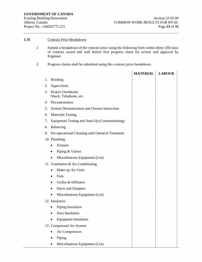
GOVERNMENT OF CANADA Existing Building Renovation Section 23 05 00
Alberta, Canada COMMON WORK RESULTS FOR HVAC
Project No.: 144202775.215 Page 23 of 35
1.35 Contract Price Breakdown
.1 Submit a breakdown of the contract price using the following form within thirty (30) days
of contract award and well before first progress claim for review and approval by
Engineer.
.2 Progress claims shall be submitted using this contract price breakdown.
MATERIAL LABOUR
1. Bonding
2. Supervision
3. Project Overheads:
Shack, Telephone, etc.
4. Documentation
5. System Demonstration and Owners Instruction
6. Materials Testing
7. Equipment Testing and Start-Up (Commissioning)
8. Balancing
9. Pre-operational Cleaning and Chemical Treatment
10. Plumbing
Fixtures
Piping & Valves
Miscellaneous Equipment (List)
11. Ventilation & Air Conditioning
Make-up Air Units
Fans
Grilles & Diffusers
Ducts and Dampers
Miscellaneous Equipment (List)
12. Insulation
Piping Insulation
Duct Insulation
Equipment Insulation
13. Compressed Air System
Air Compressors
Piping
Miscellaneous Equipment (List)
GOVERNMENT OF CANADA Existing Building Renovation Section 23 05 00
Alberta, Canada COMMON WORK RESULTS FOR HVAC
Project No.: 144202775.215 Page 24 of 35
MATERIAL LABOUR
Meters and Gauges
14. Duct Cleaning
15. Controls
TOTAL (TO EQUAL CONTRACT PRICE)
2. Products
2.1 Operating and Maintenance Manuals
.1 Comply with Division 01:
.1 Closeout Procedures Section 01 77 00
.2 Closeout Submittals Section 01 78 00
.3 Building Management Manual Section 01 91 51
.2 Binders
.1 Provide four (4) sets of Operations and Maintenance Manuals.
.2 Each set of manuals shall include as many binders as required to accommodate
the project information.
.3 Binders shall be 216mm (8½”) x 280mm (11”), three (3) post, expanding spine
type, with metal piano hinges and bound with heavy fabric.
.4 Maximum binder thickness when filled shall not exceed 100mm (4”), including a
space allowance for 10% additional data.
.5 Binder color shall be blue, Ontario buckram fabric, color #OBV460.
.6 Project title and identification shall be silk screened on the front cover and spine.
All lettering and borders shall be white.
.7 Binder spine identification to include Volume #, Set #, Title Description, Facility
Name and Facility Location. Title of the project is to be as per title on drawings
cover sheet.
.8 Contractor to submit proof of cover layout for review prior to ordering binders.
.9 In addition to the hard copies, an electronic version of the Operating and
Maintenance manuals are to be provided in PDF on a CD.
.3 Tabs
GOVERNMENT OF CANADA Existing Building Renovation Section 23 05 00
Alberta, Canada COMMON WORK RESULTS FOR HVAC
Project No.: 144202775.215 Page 25 of 35
.1 The divider tabs shall be laminated mylar plastic and colored according to
division and section.
.2 Plastic tabs with typewritten card inserts will not be accepted.
.3 Each tab to include tab number and title printed on the tab.
.4 The coloring for tabs for individual sections is as follows:
Green: Air Systems
Brown: Control Systems
Yellow: Miscellaneous Systems
Purple: Plumbing Systems
.4 Manual Divisions
.1 Organize each manual into the following divisions.
.1 Operation Division
.2 Maintenance Division
.3 Contract Documentation Division
.5 Operations Division
.1 The operations division shall have all data organized into sections according to
the system category with individual divider tabs as follows:
.1 AIR - Air Systems
.2 CTL - Control Systems
.3 MIS - Miscellaneous Systems
.4 PLG - Plumbing Systems
.2 Organize data for each system category (section) into individual sub-systems.
Provide an index for each system category and a divider tab for each individual
system.
.3 For each individual sub-system include the following:
.1 System Description - Provide details of system type, composition, areas
served, location in the building, design criteria and function of major
components. All equipment arranged to operate together as one system
shall be considered part of that system description. Design criteria shall,
at minimum, include the following:

GOVERNMENT OF CANADA Existing Building Renovation Section 23 05 00
Alberta, Canada COMMON WORK RESULTS FOR HVAC
Project No.: 144202775.215 Page 26 of 35
.1 Occupied space conditions
.2 Outdoor ambient conditions
.3 Air circulation rate
.4 Exhaust air rate
.5 Minimum outside air
.6 Building pressurization
.2 System Schematics - Provide a system schematic showing all
components comprising the central system. Identify each component
using DDC system mnemonic and generic name designation. Use this
equipment designation in all references to the equipment throughout the
manual.
.1 System schematics shall include at a minimum:
.1 Ventilation systems
.2 Compressed air system
.3 Operating Instructions - Provide, in "operator" layman language, the
specific instructions for start-up, shutdown and seasonal change over of
each system component. Include exact type and specific location of each
switch and device to be used in the system operation. Identify safety
devices and interlocks that must be satisfied in order for the equipment to
start. Also, list conditions to be fulfilled before attempting equipment
start-up, i.e. valves position correct, glycol mixture concentration proper,
piping filled with fluid, filters/strainers in place, etc.
.4 Equipment Identification - Provide data for each system component on
equipment identification forms equal to the standard forms obtained from
the design consultant.
.1 The consultant shall provide one sample reproducible copy of a
form for use by the contractor. New forms produced by the
contractor shall follow the same format as the sample form and
contain all required information.
.5 Maintenance Division
.1 Organize data into the following sections with divider tabs:
.1 Maintenance Tasks and Schedules
.2 Spare Parts
.3 Suppliers and Contractors
GOVERNMENT OF CANADA Existing Building Renovation Section 23 05 00
Alberta, Canada COMMON WORK RESULTS FOR HVAC
Project No.: 144202775.215 Page 27 of 35
.4 Tags and Directories
.2 Maintenance Tasks and Schedules - Organize data according to
the system category, with further breakdown into individual
systems as used in the operations division of the manual.
Provide section index and divider tabs for each system category.
Summarize maintenance tasks from manufacturers maintenance
brochures, for each component of each system in the following
format:
.1 Daily
.2 Weekly
.3 Monthly
.4 Semiannually
.5 Annually
.6 When Required.
.3 Spare Part List - Organize data according to the system category,
with further breakdown into individual systems as used in the
operations division of the manual. Provide section index and
divider tabs for each system category. Summarize from
manufacturers maintenance brochures the recommended spare
parts for each component of each system.
.4 Suppliers and Contractor List - Provide summary of Suppliers
and Contractors for each components of each system. List name,
address and telephone number of each.
.5 Tags and Directories - Provide a copy of the Mechanical
Drawing, List, Valve Tag List, Piping Identification Schedule
and all other directories as specified in the contract documents.
.6 Contract Documentation Division
.1 Organize all data required by the construction contract into
sections, with divider tabs, as follows:
.1 Drawings List
.2 Shop Drawings and Product Data
.3 Certifications
.4 Warranties and Bonds
.5 Maintenance Brochures

GOVERNMENT OF CANADA Existing Building Renovation Section 23 05 00
Alberta, Canada COMMON WORK RESULTS FOR HVAC
Project No.: 144202775.215 Page 28 of 35
.6 Reports
.2 Shop Drawings and Product Data - Provide final copies of all
shop drawings and product data required by the contract
documents. Include section index and divider tabs. Maximum
of twenty-five (25) sheets or one (1) system shop drawing per
tab.
.3 Certifications - Provide copies of Contractor Certifications for
the performance of product and systems. Include copies of all
pressure tests for piping and ductwork systems, equipment
alignment certificates, local authority inspection reviews,
backflow prevention certification, and fire protection
certifications. Include section index and divider tabs with
maximum of twenty-five sheets (25) or one report per tab.
.4 Warranties and Bonds - Include one copy each of the
Contractor's warranty, manufacturers' warranties longer than one
year, the bond, and any service contract provided by the
contractor. Provided section index.
.5 Maintenance Brochures - Include copies of all manufacturers'
printed maintenance brochures pertaining to each product,
equipment or system. provide section index and divider tabs.
Maximum of twenty-five (25) sheets or one system brochure per
tab.
.6 Reports - Include copies of all reports relating to the testing,
adjusting and balancing of equipment and systems, water
treatment reports and manufacturer’s start-up reports, as required
by the contract specification sections.
.7 Submissions and Approvals
.1 First Draft Submission
.1 Contractor shall submit a draft copy of the operations
and maintenance manuals for format review at the 50%
construction completion stage.
.2 The draft submission is to be bound in 3 ring loose leaf
type binders and shall include the following information:
.1 A table of contents for the complete manual.
.2 Index of each division of the manual.
.3 Index of each section of the operations and
maintenance divisions.
GOVERNMENT OF CANADA Existing Building Renovation Section 23 05 00
Alberta, Canada COMMON WORK RESULTS FOR HVAC
Project No.: 144202775.215 Page 29 of 35
.4 A sample operations division write-up for a
typical system, including sample schematic.
.5 A sample maintenance division write-up for the
same typical system.
.6 Sample proof of binder covers and spines.
.3 On completion of review of the first draft submission the
consultant will return the copy of the manual with
review comments for resubmission.
.2 Provisional Edition
.1 The contractor shall submit two (2) copies of the
provisional edition of the manual at the 75%
construction completion stage.
.2 The provisional edition shall be complete in all respects,
except for reports and certificates to be produced during
the facility start-up phase. This manual shall have the
same physical format, including divider tabs and indices,
as the final edition of the manual. This provisional
edition may be bound in standard three-ring loose leaf
binders.
.3 One copy of the provisional edition shall be kept on site
as an interim reference for all parties engaged in the
facility start-up phase, and shall be used to familiarize
and train the operating staff.
.4 The second copy shall be returned to the contractor with
review comments.
.5 The contractor shall update contents of the site copy of
the provisional edition manual as new information is
generated during the facility start-up phase.
.3 Final Edition
.1 Prior to final acceptance the contractor shall submit four
(4) copies of the final edition of the manual.
.2 This final edition shall include all outstanding project
information and conform to all requirements listed in
this document.
GOVERNMENT OF CANADA Existing Building Renovation Section 23 05 00
Alberta, Canada COMMON WORK RESULTS FOR HVAC
Project No.: 144202775.215 Page 30 of 35
3. Execution
3.1 Demonstrations – General
.1 Mechanical Trade shall arrange for presentation and demonstration of HVAC equipment
and systems by appropriate specialists and shall ensure that required manufacturer's
representatives are in attendance.
.2 Coordinate demonstration and instruction agenda and schedule with the Owner and
Engineer.
.3 Coordinate demonstration and instruction agenda and schedule for work performed
outside the contract with the owner and engineer.
.4 Provide personnel when necessary to ensure proper detailed training is provided for all
mechanical systems.
.5 Do not commence the instructional period until all mechanical systems are complete and
proven operational.
.6 Include in the operating and maintenance manuals all instructions and information given
to owner’s staff and instructions and information given by equipment manufacturer’s
representatives.
3.2 Demonstrations – Equipment & Systems
.1 Demonstrate specific starting and stopping and general maintenance requirements for
each major piece of equipment. Ensure all labeling and identification is completed.
.2 Demonstrate the following systems, in the form of instruction seminars and contractor-
guided tour of the facility.
.1 Air Systems
.2 Control Systems
.3 Balancing
.4 Plumbing Systems
.3 Demonstrate the following pieces of equipment.
.1 Fans/Makeup Air Units
.4 Refer to sample mechanical system agenda schedules in section 3.3 following for
identifying the proposed sequence of demonstrations. Sequence of demonstration and
duration of training seminars to suit project. Submit agenda for review by Engineer one
month prior to demonstration.
.5 Answer all questions raised by Owner at demonstrations; if unable to satisfactorily
answer questions immediately, provide written response within three (3) days.

GOVERNMENT OF CANADA Existing Building Renovation Section 23 05 00
Alberta, Canada COMMON WORK RESULTS FOR HVAC
Project No.: 144202775.215 Page 31 of 35
.6 Provide sign off sheets for each session. Sign off sheets to have attendees, date, subject,
presentation by and comments. Attach the sign off sheets to the agenda and submit a
copy to the engineer following training seminars.
3.3 Mechanical Systems Agenda (Sample)
Mechanical Systems Agenda
Topic: Heating System
Day: 1. Start Time: 8:00 am
2. Meeting Place:
Approximate Duration: 7.5 hours
Agenda: 1. 8:00am – Classroom Presentation
2. Contractor / Supplier:
Lunch Break: 12:00pm to 1:00pm
Agenda: 1. 1:00pm – Site Walkthrough
2. 4:00pm – Final Questions and Sign-off Log Sheet
Personnel to be in Attendance:
1. Mechanical Contractor and Sub-Trades (as required)
2. Maintenance Staff
Presentation Format:
Classroom:
Introduction:
1. Pass out hand-outs of system description
2. Reference to equipment operation brochures as required
3. Detailed system overview by Mechanical Trade, Sub-Trades and Suppliers
4. Review of system installations by the Mechanical Trades using record
drawings
Site Tour:
1. Mechanical Trade to outline location of main piping runs, isolation valves,
service access points.
2. Review service procedures for heating boiler and circulation pumps.
3. Terminal hot water heating units to be reviewed for service and operation.
GOVERNMENT OF CANADA Existing Building Renovation Section 23 05 00
Alberta, Canada COMMON WORK RESULTS FOR HVAC
Project No.: 144202775.215 Page 32 of 35
4. Coils, expansion tanks and accessories to be reviewed for service and
operation.
5. Equipment to be reviewed and dismantled as required to demonstrate servicing.
6. Gas Fired equipment to be reviewed and dismantled as required to demonstrate
servicing and operation.
7. Provide written instructions on how to start and stop all equipment and
demonstrate using instructions during tour.
3.4 HVAC Equipment Testing and Startup – General
.1 Conduct performance tests to demonstrate equipment and systems meet specified
requirements after mechanical installations are completed and pressure tested. Conduct
tests as soon as conditions permit. Make changes, repairs, and adjustments required prior
to operating tests.
.2 Meet with Division 26 manufacturers, suppliers, and other specialists as required to
ensure all phases of work are properly coordinated prior to commencement of each
particular testing procedure. Establish all necessary manpower requirements.
.3 Gas fired appliances rated in excess of 17 kW (400 MBH) shall be subjected to an
operational test established by the Gas Protection Branch and shall pass this test before
being approved for operation.
.4 Operate and test motors and speed switches for correct wiring and sequences and
direction of rotation. Check and record overload heaters in motor starters.
.5 Confirm voltages and operating amperages at full load.
.6 Tests to be maintained for a period of eight (8) hours minimum for each system. Test for
air and water flow and temperature and humidity to demonstrate compliance with design
requirements.
.7 During test, make adjustments to bring equipment up to the required standards with
respect to performance, vibration, noise, etc.
.8 Conduct final operating tests in presence of the owner. Vary loads to illustrate start-up
and shut down sequence and simulate emergency conditions for safety shut downs, with
automatic and manual reset. Repair and test defects until satisfactory. Make final
adjustments to suit exact building conditions.
.9 Provide services of one job mechanic, ladders, tools and associated equipment required to
assist in final tests. Owner’s personnel may witness all tests.
.10 Lubricate bearings, adjust and/or replace and set direct and ‘V’ belt drives for proper
alignment and tension.
.11 Calibrate and adjust thermostats, thermometers and gauges. Control valves shall operate
freely.
GOVERNMENT OF CANADA Existing Building Renovation Section 23 05 00
Alberta, Canada COMMON WORK RESULTS FOR HVAC
Project No.: 144202775.215 Page 33 of 35
.12 Operate and test motors for correct wiring and sequences. Check overload heaters in
motor starters are within the constraints of Division 26 requirements. Replace heaters if
required to suit as installed condition.
.13 Remove and clean strainers.
.14 Fasten loose and rattling pieces of equipment. Pumps and other equipment shall operate
quietly.
.15 Failure to follow instructions pertaining to correct starting procedures may result in re-
evaluation of equipment by an Independent Testing Agency selected by Owner at
Contractor's expense. Should results reveal equipment has not been properly started,
equipment may be rejected, removed from site, and replaced. Replacement equipment
shall also be subject to full starting procedures, using same procedures specified on the
originally installed equipment.
3.5 HVAC Equipment Testing and Startup – Procedures
.1 Procedure shall be identified in the following five (5) distinct phases:
.1 Pre-Starting: Visual inspection.
.2 Starting: Actual starting procedure.
.3 Post-Starting: Operational testing, adjusting or balancing, and equipment run-in
phase.
.4 Pre-Interim Acceptance of the Work: Final cleaning, re-testing, balancing and
adjusting, and necessary maintenance.
.5 Post-Interim Acceptance of the Work: Repeat tests and fine-tuning resulting
from corrective action of deficiency clean-up.
.2 Check specified and shop drawing data against installed data.
.3 Check the installation is as defined by contract documents and as per manufacturer's
recommendations including manufacturer's installation check sheets.
.4 Include for the costs of an independent testing agency, selected by the Owner, to take
samples of all chemically treated hydronic systems, perform lab analysis of the chemical
treatment levels, and submit a written report of their findings to the Owner. Should
chemical treatment levels not meet the requirements of the specifications, the Contractor
shall adjust treatment levels accordingly and cover the costs of the independent testing
agency to take additional samples and tests.
3.6 HVAC Equipment Testing and Startup – Contractor Testing Responsibilities
.1 The contractor shall be required to provide the following tests as part of his construction
contract. For each test, a test form is to be filled out, witnessed, kept on site for the
GOVERNMENT OF CANADA Existing Building Renovation Section 23 05 00
Alberta, Canada COMMON WORK RESULTS FOR HVAC
Project No.: 144202775.215 Page 34 of 35
consultant to verify at any time during construction and then they are to be included in
the final submission of the contractor O & M manuals.
.1 Plumbing Systems
.1 Piping
.1 Test as per the requirements of the National Plumbing Code
2010.
.2 Air Compressors
.3 Air Systems
.1 Fans
.1 Check radiated and discharge sound power levels
.2 Determine rpm, air flow rates, static pressure and record on the
fan curves
.3 Conduct fan performance test for total system volume on main
air supply and exhaust units
.4 Conduct smoke control test to meet occupancy requirements
.2 HEPA Filters
.1 Test as per standard 209B, 209D and DOP
.3 Air Outlets
.1 Take sound readings at specified air flows at outlets
.4 Fire Dampers
.1 Test each damper to ensure proper blade movement and damper
closure
.2 Verify damper accessibility for changing of the fusible links
.5 Ductwork
.1 Low pressure supply, return and exhaust ductwork is to be
pressure tested as per requirements of Section 23 31 13.
.2 Medium and high pressure supply, return and exhaust ductwork
is to be pressure tested as per requirements of Section 23 31 13.
.4 DDC Control System
GOVERNMENT OF CANADA Existing Building Renovation Section 23 05 00
Alberta, Canada COMMON WORK RESULTS FOR HVAC
Project No.: 144202775.215 Page 35 of 35
.1 General
.1 Conduct system 7 day performance test to prove communication,
loop tuning and control sequences
.2 Variable Frequency Drives
.1 Test as per the requirements of Section 23 05 04 – Variable Frequency Drives for
HVAC Equipment.
END OF SECTION
GOVERNMENT OF CANADA Existing Building Renovation Section 23 05 04
Alberta, Canada VARIABLE FREQUENCY DRIVES
Project No.: 144202775.215 FOR HVAC EQUIPMENT
Page 1 of 27
1. General
1.1 Scope
.1 This section includes the supply, installation, start-up, testing and commissioning for
variable frequency drives (VFD) controllers, including but not limited to: associated
enclosures, input and output filters, warranty, local and remote control.
.2 The VFD and all specified components, including internal wiring between those
components, must be installed and integrated into one common enclosure, supplied,
factory tested, and commissioned by the VFD supplier. The integrated VFD assembly
shall be ready for filed installation and require only the connection of the incoming power
cables, the motor load cables, and the control wiring for start-up, and the commissioning
of the VFDs.
.3 The VFD supplier must coordinate with the installation contractor with respect to
delivery dates, technical support for the installation, equipment start-up, and the
commissioning of the VFDs.
.4 All drives and ancillary components specified in this section to be supplied by one
manufacturer to assure a properly coordinated system.
.5 Design all equipment using modularized solid state equipment to allow easy maintenance
and replacement.
1.2 Submittals
.1 Comply with the requirements of Section 23 05 00 – Common Work Results for HVAC.
.2 Provide the following shop drawing information:
.1 Catalog and technical data.
.2 Outline dimensions, shipping section dimensions, weight, and foundation
requirements for all assemblies.
.3 Physical details of the cabinets, a wiring diagram, and a ladder diagram showing
both internal connections and terminals for field wiring, showing function and
identification of all terminals requiring field connections. Separate diagrams are
required for each VFD size. Generic diagrams are not acceptable.
.4 Component fabrication drawings consisting of detailed circuit schematics,
indicating all components in the VFD package, including line and load reactor
impedance ratings and/or filter design type, VFD current, HP and voltage rating.
.5 Bolt and lug torque schedule for all power and control wiring termination points.
.6 Vendor’s start-up sheets for the drive.
GOVERNMENT OF CANADA Existing Building Renovation Section 23 05 04
Alberta, Canada VARIABLE FREQUENCY DRIVES
Project No.: 144202775.215 FOR HVAC EQUIPMENT
Page 2 of 27
.3 Upon delivery, provide as-built shop drawings for each unit. A copy of the as-built shop
drawings shall be provided for each drive in addition to one set of drawings for each copy
of the O&M Manuals. (See info in the project specifications and drawings for quantities
in addition to that indicated herein, the quantities shall be the maximum indicated plus 1
copy for each drive).
.4 Supply four (4) copies of Operation and Maintenance manual containing data for each
VFD. Data shall include:
.1 Troubleshooting charts for all device faults.
.2 An instruction manual for: programming and the hardware provided with the
equipment at time of shipment.
.3 Manufacturer’s start-up check sheet(s) with list(s) that outline all of the
completed tasks. Check-sheets are to contain actual start-up data and shall list all
settings and parameters present in the drive unit as commissioned.
.4 VFD field-test measurement results. All data provided shall be that from the last
testing conducted on the drive. If original testing was redone, then the new data
shall be provided in addition to the original data Original tests must then be
marked “Superseded. For Information Only”. All test data shall be dated and
signed".
.5 Settings sheets to record all VFD configuration options and selections for VFD
set-up. Settings sheets are to contain actual start-up data and shall list all settings
and parameters present in the drive unit as commissioned.
.6 Include a list of authorized recommended spare parts, service depots, spare parts
list.
.5 Provide copies of the VFD programming / troubleshooting software, as well as any
connection cables required, to Owner. Provide one set of software and cabling, for each
size of drive, for each O&M manual provided.
1.3 Delivery & Storage
.1 Deliver and store materials in accordance with Section 23 05 00 – Common Work
Results for HVAC.
1.4 Waste Management and Disposal
.1 Separate waste materials for reuse and recycling in accordance with Section 23 05 00 –
Common Work Results for HVAC.
1.5 Related work specified in other sections
.1 Common Work Results for HVAC Section 23 05 00
.2 Common Motor Requirements for HVAC Equipment Section 23 05 13
GOVERNMENT OF CANADA Existing Building Renovation Section 23 05 04
Alberta, Canada VARIABLE FREQUENCY DRIVES
Project No.: 144202775.215 FOR HVAC EQUIPMENT
Page 3 of 27
.3 Testing, Adjusting and Balancing for HVAC Systems Section 23 05 93
.4 Electrical Division 26
1.6 Standards
.1 VFD units shall be ULC listed and CSA (or cUL) certified.
.2 VFD units shall comply with applicable requirements of the latest standards of CSA,
ANSI, IEEE 519, NEMA MG1 and the Canadian Electrical Code.
1.7 Intended operation
.1 The VFD shall be designed to operate standard squirrel cage induction motors with a 1.0
service factor meeting NEMA MG1 Part 31. Refer to Section 23 05 03 – Electric Motors
– 600V or less.
.2 The VFDs shall control one of more fan motor(s) or pump motor(s) as listed in the
drawing schedules.
.3 The VFD shall communicate with, and be controlled by, the building automation system
(BAS) which will provide Run Command and an Operating Speed reference to the VFD.
VFD Run Status, Operating Speed, Load Amps, Power and Alarm or Fault data shall be
communicated back to the BAS. The VFD shall also be capable of operating in PID
Mode with the Run Command and PID Set Point communicated by the BAS. A process
monitoring transmitter (supplied by the controls contractor) will be connected directly to
the VFD. Refer to Controls, Sections 23 09 Series.
.4 Communication with the BMS shall be BACnet MSTP over EIA-485.
1.8 Factory Testing
.1 Prior to shipment, all VFD units are to be shop-tested at the factor or at the VFDs
OEM/integrator’s facilities. Testing shall include, but will not be limited to, a complete
functional test to fully prove out the VFD and all the local and remote control functions
and required parameter settings. Phase-loss protection for each of the 3 phases of the
VFD shall be proven as part of the factory testing.
.2 Provide factory-certified copies of production test results to the Engineer prior to
shipment of the equipment.
1.9 Harmonic Guidelines
.1 All VFD installations shall meet IEEE-519-1992 harmonic guidelines.
.2 Following award of contract, and prior to submitting shop drawings, the VFD vendor
shall review the electrical system design and MCC locations and advise if filtering, in
addition to the specified line reactors, is required.
GOVERNMENT OF CANADA Existing Building Renovation Section 23 05 04
Alberta, Canada VARIABLE FREQUENCY DRIVES
Project No.: 144202775.215 FOR HVAC EQUIPMENT
Page 4 of 27
1.10 Warranty
.1 The VFD supplier shall provide warranty coverage for a minimum period of twelve (12)
months commencing upon the date of substantial completion. Refer to Division 0 and
Division 1.
.2 The Vendor shall be responsible to bring a Factory Representative back to reset, repair,
and re-commission the VFD if problems arise with the normal operation of that VFD
during the warranty period.
1.11 Maintenance
.1 VFD supplier is to include a preventative maintenance program (PMP) for a one year
period. The PMP is to be broken down to daily, weekly, monthly and annual service
periods. Each service period is to include all manufacturer recommended maintenance
tasks which should be completed in each period. A maintenance checklist is to be cross
referenced to the maintenance period and maintenance task.
1.12 Training
.1 Provide an on-site, half day training seminar for maintenance and service personnel.
.2 The VFD supplier shall detail an agenda for the training to be provided and to present it
to the Engineer for review and adjustment. Refer to Section 23 05 06 – Demonstration
and Owner’s Instruction for HVAC Systems.
.3 The Vendor shall comply with the Engineers requests for modification of the content to
suit its needs within the four (4) hour time allowance. The training agenda shall be
provided four (4) weeks prior to the drive start-up, and the VFD Supplier shall schedule
the timing & location of the seminar at a time and location suitable to the Engineer.
.4 Refer to and comply with Section 20 05 06, Systems Demonstration and Owner’s
Instruction.
2. Products
2.1 Section Includes:
.1 Approved VFD Suppliers and Product
.2 Vendor Requirements – Service and Support
.3 General VFD Requirements
.4 Environmental Capabilities
.5 Input Power
.6 Output Power
GOVERNMENT OF CANADA Existing Building Renovation Section 23 05 04
Alberta, Canada VARIABLE FREQUENCY DRIVES
Project No.: 144202775.215 FOR HVAC EQUIPMENT
Page 5 of 27
.7 Equipment Protection
.8 Approved Filter Manufacturers
.9 Integrated VFD Equipment Enclosure
.10 BACnet
.11 PID Control
.12 Control and Operational Features
.13 Drive Control (Hand operation)
.14 Drive Controls (Auto Operation)
.15 Isolated Bypass Operation
.16 Drive Parameter Settings
.17 Diagnostics
.18 Drives Connected to Emergency Power System
.19 Wiring and Identification
2.2 Acceptable Products
.1 Variable Frequency Drive (VFD) as supplied by:
.1 ABB
.2 Cutler Hammer
.3 Danfoss
.4 General Electric
.5 Siemens
.6 TECO-Westinghouse
.7 Mistubishi (MGI)
2.3 vendor requirements – Service and Support
.1 The drive vendor must provide a factory-trained sales force locally available for
applications assistance and to answer maintenance questions.
GOVERNMENT OF CANADA Existing Building Renovation Section 23 05 04
Alberta, Canada VARIABLE FREQUENCY DRIVES
Project No.: 144202775.215 FOR HVAC EQUIPMENT
Page 6 of 27
.2 The vendor must have a distributor organization, which locally stocks standard drives,
modification kits, and spare parts.
.3 The vendor must have factory-trained service representatives within the local Edmonton
area. The factory representatives must be trained in the maintenance and troubleshooting
of the equipment as specified herein.
.4 Vendor must provide regularly scheduled maintenance and training schools in Canada on
the equipment supplied
2.4 General VFD Requirements
.1 All units shall be ULc or CSA approved.
.2 VFD unit shall comply with applicable requirements of the latest standards of CSA,
ANSI, IEEE, NEMA, and the Canadian Electrical Code.
.3 Unless otherwise noted, all horsepower/kW ratings are to be based on a Variable Torque
load.
.4 VFD shall be provided with a CSA (NEMA) Type 1 enclosure.
.5 The VFD shall be rated for continuous duty while operating a NEMA design induction
motor of the sizes and operating voltages as shown in the applicable schedules and
indicated on the drawings.
.6 The VFDs shall have a current rating at least 10% in excess of the motor full load amp
rating. When subject to the range of ambient conditions, the VFD to be capable of
delivering 110% of rated output current for up to one minute for variable torque loads
.7 The VFD shall have a fixed bridge type converter (PWM) utilizing Insulated Gate
Bipolar Transistor (IGBT) technology.
.8 VFD operation to be fully digital with microprocessor control of frequency, voltage, and
current.
.9 Efficiency of VFD controller shall not be less than 97.5% at 60 Hz output at 100% rated
load.
2.5 Environmental Capabilities
.1 The drive shall operate without mechanical or electrical damage under any combination
of conditions as follows:
.1 Ambient temperature: 0 to 40C (32F to 105F)
.2 Humidity: 5 to 95% (non condensing)
.3 Vibration: up to 0.5 G
GOVERNMENT OF CANADA Existing Building Renovation Section 23 05 04
Alberta, Canada VARIABLE FREQUENCY DRIVES
Project No.: 144202775.215 FOR HVAC EQUIPMENT
Page 7 of 27
.4 Altitude: 0 to 1200m (0 ft to 3940 ft); For altitudes above 1200m (3960 ft), the
equipment must be properly de-rated such that the higher altitude rating is greater
than the required output.
.5 The VFD unit may require fan-assisted cooling to ensure adequate heat
dissipation. Such a system shall be installed in a manner that does not degrade
the enclosure rating. Provide alarm status and shut-down for the VFD, on
excessive temperature rise in the enclosure, for VFDs that utilize forced air fans
for enclosure cooling.
2.6 Input Power
.1 Input voltage shall be as indicated on motor schedules and drawings, line voltage
variation (10%), 3 phase, 60 Hz, grounded power supply without high or low line
tripping. Confirm voltage before ordering.
.2 The VFD must be capable of operating under the following conditions without high or
low line tripping: 3 phase, 60Hz, alternating current, grounded power supply, line voltage
as shown (240,480, 600) ±10%. Speed stability shall be ±1%.
.3 Permit power line interruptions for high inertia loads such as fans and centrifuges for at
least 2.0 seconds without the VFD shutting down on a fault providing an extended power
loss ride-through. If the drive trips on undervoltage, the drive will activate the Automatic
Restart. See “Rotating Start” clause 2.13.17.
.4 The VFD shall present a displacement power factor of 0.98 or better to the AC line over
10% to 100% speed range. Full load effective power factor shall be 96% or better.
.5 The VFD must operate satisfactorily when connected to a bus supplying other solid state
power conversion equipment which may be causing up to 5% total harmonic voltage
distortion and communication notches up to 36,500 volt microseconds.
.6 Normal power distribution is subject to voltage surges and sags as a normal condition of
operation. Design and supply with each VFD the required inverter protection such that
the VFD will not be stressed or damaged, in the following conditions:
.1 Line surges of up to 115% of rated voltage for up to 10 cycles. Based on
347/600 Volt systems.
.2 Line voltage sags down to 85% of rated voltage of up to 1 second duration.
.7 Provide a 5% impedance line reactor at in the drive input to protect electronic
components from transient voltage conditions and to reduce harmonic current distortion.
.8 The VFD must not be sensitive to supplied power that has one phase grounded (Delta –
with balanced voltages) or referenced to earth ground (Wye).
.9 The VFD must not be sensitive to incoming phase sequence.

GOVERNMENT OF CANADA Existing Building Renovation Section 23 05 04
Alberta, Canada VARIABLE FREQUENCY DRIVES
Project No.: 144202775.215 FOR HVAC EQUIPMENT
Page 8 of 27
.10 VFDs shall be of the 6-pulse PWM- type complete with an external AC line reactor to
reduce harmonic current distortion.
2.7 Output Power
.1 The VFD shall produce a 3 phase output for motor loads.
.2 Pulse-Width Modulating (PWM) circuitry must consist of a full wave diode bridge
converter to convert incoming fixed voltage and frequency to a fixed DC voltage. The
Pulse Width Modulation strategy shall incorporate a microprocessor to handle all Logic
functions as well as the complex, sine-coded PWM generating algorithms that control
output stage switching.
.3 Generate the inverter output by IGBT power transistors only.
.4 The VFD output waveform to be the PWM or Vector type waveform producing smooth
torque at low frequencies and low motor current harmonics.
.5 Harmonic loading shall not exceed the maximums acceptable for motor operation with a
service factor of 1.0.
.6 The VFD output voltage shall be user-adjustable to deliver voltage from 0 V to full
voltage at 60 Hz.
.7 The VFD shall be provided with user-adjustable settings to provide a frequency range of
0 to 120 Hz.
.8 Unless otherwise specified, the VFD output voltage to be adjustable from 0 to full
voltage reaching full voltage at 60 Hz.
.9 Provide selectable constant V/Hz ratio PWM or variable V/Hz for Variable Torque loads.
.10 The VFD must maintain capability for 100% of rated output current continuously,
regardless of change in ambient conditions throughout its listed ambient conditions range.
.11 PWM carrier frequency shall be user-selectable.
.12 Manufacturer to indicate, at time of tender, the anticipated levels of electrical noise and
heat generated. In any case, the Audible noise levels to be less than 85 dbA at 1 m out
from any point on the VFD cabinet under normal operating condition, with the drive at
full load.
.13 Radio Frequency Interference (RFI) must be limited to levels specified in applicable
standards. Equipment must be designed that use of radio communication equipment
adjacent to VFD units is permissible. In addition, the VFD must not be susceptible to
interference from radio equipment operated adjacent to it.

GOVERNMENT OF CANADA Existing Building Renovation Section 23 05 04
Alberta, Canada VARIABLE FREQUENCY DRIVES
Project No.: 144202775.215 FOR HVAC EQUIPMENT
Page 9 of 27
2.8 Equipment Protection
.1 Protective devices to be incorporated are:
.1 Three-pole fused disconnect switch to provide over-current protection with fuses
rated at not more than 150% of drive input current rating, except if the VFD is
specifically marked with a recommended rating for its over-current protection,
then the VFD marking shall take precedence.
.2 The operation of the disconnect switch shall be interlocked with the VFD
enclosure door. It shall not be possible to open the door without the disconnect
being in the open position. A manual means to defeat this interlock for
maintenance purposes shall be included, and the external operator handle for the
switch must have lock-out capability.
.3 The symmetrical short-circuit interrupting rating shall be verified for every
installation, and be coordinated with the VFDs electronic protection circuits.
VFD supplier is responsible to obtain SSCIR information from the designer or
design documents for the VFDs being constructed for the project.
.4 Integral electronic motor overload protection adjustable up to 150% of motor
rating for 60 seconds.
.5 Ground fault protection.
.6 Over-voltage/over-current DC bus monitor/protection.
.7 Under-voltage protection, 85% of rated input voltage.
.8 Loss of phase and phase unbalance protection.
.9 Inverter over-temperature protection.
.10 Motor overload protection, adjustable 80 to 115% of FLA of motor.
.11 Where bypass contactors are utilized or where the VFD serves several motors,
provide external dial adjustable motor overload protection relays with inherent
single-phase protection. The current range of the overload block shall be selected
to place the full-load current of the motor at approximately the centre of the dial
scale for the supplied overload relay.
.2 Include provision for adequate grounding within the equipment in addition to that
provided to safeguard against electrostatic discharge damage.
2.9 Approved Filter Manufacturers
.1 All applications with non-VFD or VFD rated motors shall require output dv/dt filters.
The following manufacturers of filters are acceptable.
GOVERNMENT OF CANADA Existing Building Renovation Section 23 05 04
Alberta, Canada VARIABLE FREQUENCY DRIVES
Project No.: 144202775.215 FOR HVAC EQUIPMENT
Page 10 of 27
.1 TCI
.2 MTE
2.10 Integrated VFD Equipment Enclosure
.1 The integrated VFD assembly, including all components shall be provided as a ventilated
CSA (NEMA) Type 1 enclosure, with a hinged, gasketed door and a drip-shield
constructed to project over the door and sized to protect all ventilation openings in the top
of the enclosure (if any) from dripping water. It shall be suitable for wall or free-standing
installation.
.2 Supply full-length painted 100mm steel channels for floor-mounted VFD enclosures.
.3 Where house-keeping pads are provided, the channel bases are not required. Where a
drive is placed on top of a housekeeping pad, base construction shall be such that the
door of the VFD will not drag on the house-keeping pad.
.4 Forced air cooled enclosures shall have filters on all air inlet openings.
.5 The backspan to be galvanized metal, non-painted, 16 gauge for EMC bonding
requirements. Provide a minimum of 2 lugs for bonding conductors (sized per CEC).
Lugs shall be bolted to the galvanized metal back-pan.
.6 Door shall be grounded with multi-conductor or braided ground strap connecting the door
to the grounding system in the enclosure interior.
2.11 BACnet
.1 The VFD shall communicate with a building automation system (BAS) network by
digital communication using the BACnet MSTP protocol (ANSI/ASHRAE Standard 135-
2004) over EIA-485.
2.12 PID Control
.1 Provide process controller circuitry incorporating a PID algorithm to control the
frequency output of the VFD.
.2 Input for the process controller shall be one of the analog input signals specified below
(clause 2.13.1).
.3 Set-point shall be reset, as selectable parameter, either by using the digital
communication network or by using the second analog input signal.
2.13 Control and Operational Features
.1 Provide two analog inputs that are both capable of receiving an input signal, user-
selectable as either 4-20 mA or 0-10 Vdc. Provide individual optically isolated inputs for
each analog signal.

GOVERNMENT OF CANADA Existing Building Renovation Section 23 05 04
Alberta, Canada VARIABLE FREQUENCY DRIVES
Project No.: 144202775.215 FOR HVAC EQUIPMENT
Page 11 of 27
.2 Process Signal Inverter: Provide programmable control to allow speed of drive to vary
inversely with input analog signal.
.3 Provide two analog outputs, individually isolated, either 0-10 Vdc or 4-20 mA, which can
be programmed to be proportional to any two of the following:
.1 Output frequency
.2 Output power
.3 Output current
.4 Provide input for external switch to be used as a proof-of-open interlock for associated
damper or valve.
.5 Provide a dry contact (output) for interlocking external devices such as signal to open a
damper or valve of associated the equipment.
.6 Provide dry-contact output to signal VFD fault.
.7 The VFD shall be capable of operating with its output open-circuited (no motor
connected), with no fault or damage, for start-up and testing purposes. The drive must be
capable of running without a motor connected.
.8 All VFD set-up operations and adjustments to be digital and stored in a non-volatile
memory (EEPROM).
.9 Local communications port: Provide a local interface to upload, download, and read drive
parameter settings, through the use of a notebook computer. Include Windows based
software for computer on CD-ROM(s) with all associated operating instructions.
Software information shall be provided with the O&M manuals.
.10 Provide offset and gain programmable functions to set operating range.
.11 The VFD shall employ a programmable rate of acceleration and deceleration, either
linear or S-curve. The VFD shall “coast” to a stop or new lower speed, if selected by the
user.
.12 Speed Droop: Provide a speed droop feature that reduces the speed of the drive on
transient overloads. The drive is to return to set speed after transient overload is removed.
If the acceleration or deceleration rates are too rapid for the moment of inertia of the load,
the drive is to automatically compensate to prevent drive trip.
.13 Speed Profile: Provide individual adjustable settings for start, stop, slope, and minimum
and maximum speed points.
.14 Bumpless speed transfer: Provide a smooth speed transfer from remote control to local
control and vise-versa, without setting the motor to zero speed.

GOVERNMENT OF CANADA Existing Building Renovation Section 23 05 04
Alberta, Canada VARIABLE FREQUENCY DRIVES
Project No.: 144202775.215 FOR HVAC EQUIPMENT
Page 12 of 27
.15 Automatic Reset and Restart: Provide automatic restart of rotating equipment following
power outage. Provide programmable automatic reset / restart after any individual trip
condition resulting from over-current, over voltage, under voltage, or over-temperature.
.16 Re-start attempt limit: for safety, the drive shall shut down and require manual reset if the
automatic reset function is not successful within a maximum of three attempts within a
user-programmed time period.
.17 Pick up a spinning-load (Rotating Start): The VFD shall be user-programmable for
rotating re-start, enabling the VFD to start into a rotating motor, regardless of direction,
without tripping offline and without setting the motor to zero speed. The VFD shall start
at the speed the motor is rotating and then accelerate the motor according to the speed
reference signal. After the VFD trips due to under-voltage and whenever any momentary
power loss occurs, the drive must activate an automatic restart mode (re-initiate and re-
start) without waiting for the rotating equipment to stop, and without operator
intervention.
.18 Torque Compensation: Provide user-programmable automatic boost in torque to handle
impulse loads or demands for fast acceleration by momentarily increasing the output volt
/ hertz ratio. When selected, the function to be operative at all speeds even under
overload conditions, and eliminates the motor speed droop that would otherwise occur.
.19 Provide adjustable skip frequencies with programmable bandwidth to avoid operation in
a resonant speed area. Provide a minimum of 3 such frequency selections.
2.14 Drive Control (Hand Operation)
.1 Provide an operator station on the drive door complete with the following features as a
minimum. The following applies to a VFD with Bypass capability. Adjust requirements
as applicable for VFDs without a Bypass starter.
.1 Control Switches
.2 Selector switch No. 1: "HAND-OFF-AUTO" operation.
.3 Selector switch No. 2: "VFD ENABLED -OFF -BYPASS ENABLED"
operation.
.4 Potentiometer for local speed adjustment in VFD mode.
.2 Pilot lights on door
.1 Input Power: "ON" pilot light
.2 VFD Status: "STOP" and "RUN" indication

GOVERNMENT OF CANADA Existing Building Renovation Section 23 05 04
Alberta, Canada VARIABLE FREQUENCY DRIVES
Project No.: 144202775.215 FOR HVAC EQUIPMENT
Page 13 of 27
2.15 Drive Controls (auto Operation)
.1 The VFD to accept an isolated output signal via the Building Management System to stop
and start the drive.
.2 The VFD to have the capability to interlock of up to 3 NIC external alarm interlocks to
shut down the VFD and provide status of the trip.
.3 The VFD to provide two (2) programmable Form C dry contact status outputs. Status of
contacts to indicate:
.1 Run
.2 Fault
.4 Controller "stop" interlock from a NC dry contact.
.5 The VFD to accept an isolated analog input speed reference of 0 to 10 VDC or 4-20 mA
from the field. The 4-20 mA analog input speed reference signal shall be optically
isolated. Calibration adjustments shall be provided for settings within the speed ranges
specified.
2.16 Isolated Bypass Operation (where specified on equipment schedule(s))
.1 Provide for an automatically controlled three-contactor isolated bypass control, integral
to the VFD enclosure.
.2 Coordinate over-current protection rating for the drive and bypass starter to protect both
devices in either mode of operation.
.3 Provide a thermal overload relay sized to protect the motor for either mode of operation.
.4 Provide a three position "HAND-OFF-AUTO" and a “VFD-OFF-BYPASS” selector
switch
.1 VFD MODE:
.1 Selector switch in "HAND" position: speed controlled by the
potentiometer.
.2 Selector switch in "OFF" position: Motor cannot be started.
.3 Selector switch in "AUTO" position: VFD operates by remote start / stop
command, the speed controlled by the isolated 0-10Vdc or 4 -20 mA
signal.
.2 BYPASS MODE:
.1 Selector switch "HAND" position

GOVERNMENT OF CANADA Existing Building Renovation Section 23 05 04
Alberta, Canada VARIABLE FREQUENCY DRIVES
Project No.: 144202775.215 FOR HVAC EQUIPMENT
Page 14 of 27
.2 Selector switch "OFF" position prevents motor from operating.
.3 Selector switch "AUTO" position allows motor to start by remote start /
stop command.
.4 All Interlocks are in the circuit for all modes of operation.
2.17 Drive Parameter Settings
.1 VFD configuring settings shall be field adjustable through the keypad and display unit or
via the serial communication port.
.2 The digital keypad must allow the operator to enter exact numerical settings. A plain
English user menu (rather than codes) shall be provided in software to guide parameter
setting. Drive parameters shall be factory set in EEPROM and be resettable by the user
through the keypad. Keypad setting shall disable parameter changes by unauthorized
personnel.
2.18 Diagnostics
.1 On power-up, the VFD shall execute a self-diagnostic check. The integral programming
display panel shall provide first fault indication of VFD protection functions. Fault
indication to be retained if input power is lost.
.2 Provide a software graphing feature for up to eight different programmable signals at the
time of a fault trip or during operation
.3 The fault log record shall be accessible via a portable computer, connected directly to
VFD, as well as from readout on the keypad display on the panel door.
.4 Fault codes shall provide direction as to board level and input–output level to aid in
trouble-shooting.
.5 The following faults to be displayed on the local programming panel:
.1 Over-current
.2 Short Circuit / Ground Fault
.3 Under voltage
.4 Over voltage
.5 Over temperature
.6 Power Supply Fault
.7 Motor stalled
.6 Diagnostic and indicating features:

GOVERNMENT OF CANADA Existing Building Renovation Section 23 05 04
Alberta, Canada VARIABLE FREQUENCY DRIVES
Project No.: 144202775.215 FOR HVAC EQUIPMENT
Page 15 of 27
.1 Power ON indication.
.2 All set points
.3 Percentage speed indicator.
.4 Overload indication.
.5 Short circuit indication.
.6 Ground fault indication.
.7 Over-voltage indication.
.8 Under-voltage indication.
.9 High temperature (controller).
.10 AC voltmeter (output).
.11 AC ammeter (output).
.12 Inverter ready.
.13 Inverter fault.
.14 External fault.
.15 Motor Frequency
2.19 Drives Connected to Emergency Power System
.1 The VFD may be supplied from an emergency power distribution system, which is
subjected to short power interruptions during test of the emergency generator system. The
VFD shall continuously operate through this test mode. See “Rotating Start”, clause
2.13.17.Refer to the VFD Schedule on drawings.
2.20 Wiring and Identification
.1 Control wiring shall be stranded TEW 105°C (220°F) rise.
.2 Terminal blocks for remote interface shall be Weidmueller SAK6N or approved
equivalent.
.3 Provide wire markers at both ends of all control wires, Electrovert type Z or approved
equivalent.
.4 Where applicable, provide lamicoid tag warning of more than one voltage and provide
caution label regarding regenerative voltage that may be present on load side of output
contactor.

GOVERNMENT OF CANADA Existing Building Renovation Section 23 05 04
Alberta, Canada VARIABLE FREQUENCY DRIVES
Project No.: 144202775.215 FOR HVAC EQUIPMENT
Page 16 of 27
3. Execution
3.1 Section Includes
.1 Installation
.2 Cabling and Grounding by Division 26
.3 Start-Up
.4 Commissioning
.5 Start-up and Commissioning Service
.6 Examination
3.2 Installation
.1 Install VFDs in accordance with the manufacturer's recommendations.
.2 Set and secure VFD assembly in place on channel bases, or on housekeeping pad as
permitted elsewhere, rigid, plumb and square to building floor and wall.
.3 Protect against dust and damage during entire construction period. If filters have been
soiled replace filter media at the end of the construction period. To this end VFD supplier
shall ship one (1) extra set of filter media for each drive equipped with filter systems
from the factory. If unused these shall be turned over to the Ownerfor future
replacements.
.4 After connections have been made, vacuum exterior and touch-up any damaged paint.
Vacuum clean the interior.
.5 Mechanical Trade shall be responsible for the supply and complete commissioning of
each variable speed drive to the satisfaction of Consultant and Owners Commissioning
Forces. Division supplying the drive shall allow for factory representative to completely
calibrate all drive circuits after installation on site. Final drive settings (the final "as left"
state) shall be as-built and changes from earlier configurations shall be dated and signed.
Copies of the data shall be provided both in the drives and the O&M Manuals for the
Project.
.6 The VFD vendor shall include for the necessary engineering, programming and on-site
commissioning related to the BACnetinterface. Include for on-site coordination and
check out with the BAS contractor, including point-to-point verification for those points
utilized in the BAS programming and graphics. This shall include for points either
hardwired as discrete points or points brought in through the BACnet interface.
.7 Prohibited locations for VFD installations are where greater than normal dust
accumulations occur and where higher than normal ambient temperatures or poor
ventilation exists. (Some examples are: near steam stations, steam converters, condensate
GOVERNMENT OF CANADA Existing Building Renovation Section 23 05 04
Alberta, Canada VARIABLE FREQUENCY DRIVES
Project No.: 144202775.215 FOR HVAC EQUIPMENT
Page 17 of 27
tanks, generators, or where passive or forced ventilation systems will bring dust into the
space).
.8 Conduit and Cable entries into VFDs shall be made through either the bottom or the side
of the unit. Top entry into VFDs by conduits or cables is not permitted.
3.3 Cabling and Grounding by Division 26
.1 Coordinate with the Electrical Trade to ensure the supply and installation of cables and
electrical connections to the VFDs are correct.
.2 Division 26 will provide separate conduits and or cables for VFD input and output power:
.1 If the VFD is not preinstalled and pre-wired as a part of a packaged mechanical
equipment assembly unit, supply, install, and connect Alcatel Drive Rx Cable (or
equal) from VFD to designated motor load for motors separated by more than 10
meters of cable length from the VFD. For motors installed at 10m or less from
the unit, the use of standard building wire inside of steel conduit and terminal
sections of seal tight flex is deemed acceptable.
.3 Supply, install, and connect the feeders with adequately sized grounding / bonding
conductors in conduit (or cable) as indicated on the project drawings and / or in the
specifications from motor control centre to VFD.
.4 Supply and install a ground conductor in each control conduit with the signal and data
control cables from Building Management System (BMS) to each VFD.
.5 If a local disconnect is required (by either the engineered design or by Canadian
Electrical Code) near the motor, the operating mechanism of the disconnecting means
shall be so constructed that an auxiliary NO-NC contact will change state when the
Switch is operated. Control wiring shall be installed between the disconnect switch and
the VFD to enable the VFD to determine if the disconnect switch is open or closed. VFD
safeties shall be enabled when the motor is disconnected on the load side of the VFD.
.6 Local motor disconnects or isolating switches for motors driven by VFDs shall be
identified with a separate lamicoid nameplate located as close as practicable to the
operating handle of the field (local) disconnecting means. Tag color shall be Orange Face
& White Core. The tag shall contain the following wording: "WARNING: Do not open
while motor is rotating! Severe damage to VFD will occur! Shut down VFD and only
then, open this Switch for Safety. Close switch prior to restarting VFD!".Warning
nameplates shall be mechanically fastened to the disconnect switch.
.7 Torque all conductors with calibrated torque wrench. Terminations to be checked,
including but not limited to, power, line, load, ground, and control. Terminations shall be
torqued to the manufacturer's recommendation.

GOVERNMENT OF CANADA Existing Building Renovation Section 23 05 04
Alberta, Canada VARIABLE FREQUENCY DRIVES
Project No.: 144202775.215 FOR HVAC EQUIPMENT
Page 18 of 27
3.4 Start-up
.1 The mechanical trade will be responsible to coordinate the installation, testing, and start-
up (prior to commissioning commencement) with other parties participating in the start-
up activities.
.2 Start-up to be accomplished as detailed in following example Vendor Start-up
Requirements. These shall be considered the minimum general requirements and shall be
in addition to the manufacturer's recommended start-up. Where the Vendor or assigned
start-up agency believes any requirement to be harmful to the drive or would invalidate
warranty, the item(s) of concern shall be identified in writing to the attention of the
Engineer.
3.5 Commissioning by Vendor
.1 The vendor shall provide start-up and commissioning of the variable frequency drive and
its optional circuits by a factory-certified service technician who is experienced in start-
up and repair services. Service technician shall be a certified journeyman electrician.
Sales personnel and other agents who are not factory certified technicians for drive repair
shall not be acceptable as commissioning agents.
.2 The Contractor, in conjunction with the mechanical trade,is responsible to schedule start
up and commissioning. Scheduling of Commissioning Activities will provide a minimum
five (5) working days notice to the vendor and Owners commissioning team prior to each
separate commissioning activity.
.3 Complete vendors commissioning consistent with factory start up forms.These shall be
considered the minimum requirements for Vendors Commissioning. Where the Vendor
or Owners Commissioning Team believes any commissioning requirement to be harmful
to the drive or would invalidate warranty the item(s) of concern shall be identified in
writing to the attention of the Engineer.
.4 Submit the following written documentation:
.1 Verification of proper wire terminations and conduit runs to and from the VFD.
.2 Completion of vendors Start-up and Commissioning Form.
.3 Verify BAS calibration.
.4 Confirm Set-up and tuning of control loop resident in the VFD.
.5 Confirm that commissioning procedures have been completed.
3.6 Owners Start-up and Commissioning Procedure
.1 Each drive will be subject to an Owners start-up and commissioning procedure (hereafter
referred to as the Owners Commissioning Team), that will include the Owner (or Owners

GOVERNMENT OF CANADA Existing Building Renovation Section 23 05 04
Alberta, Canada VARIABLE FREQUENCY DRIVES
Project No.: 144202775.215 FOR HVAC EQUIPMENT
Page 19 of 27
agent), mechanical trade, electrical trade, and the VFD Vendor.Refer to thesample
Owners Commissioning Team check sheet, Article 3.9 that may be utilized by the Owner.
.2 Provide the Owners Start-up &Commissioning Team with 7 days’ notice of VFD start-
up. They may elect to witness the vendors’start-up. Vendors’ start-up services shall
include checking and verifying proper installation and operation of the VFD, its installed
options, and its interface to the building automation system as a minimum.
.3 Owners Start-Up and Commissioning Team will verify the programming of the VFD and
will provide a written copy of the settings to the Engineer.
.4 Owners Start-Up and Commissioning Team willidentify critical frequencies that may
occur throughout the operating curve of the equipment.Vendor shall program the drive to
run through the critical frequencies that have been identified.
3.7 Examination
.1 The Contractor is to verify that the jobsite conditions for installation meet the factory
recommendations and code required conditions for the VFD installation prior to start-up.
These shall include as a minimum:
.1 Clearance spacing.
.2 Compliance with environmental ratings of the VFD system.
.3 Separate conduit installation of the input wiring, the motor wiring, and control
wiring.At no time does any of this wiring run in parallel with each other.
.4 All power and control wiring is complete.
.5 Site has been suitably cleaned.
.2 The VFD is to be covered and protected from installation dust and contamination until
the environment is cleaned and ready for operation. The VFD system shall not be
operated while the unit is covered.
3.8 VFD Schedule
.1 Supply, install, start up, and commission VFD’s serving motors on mechanical equipment
as scheduled on drawings:
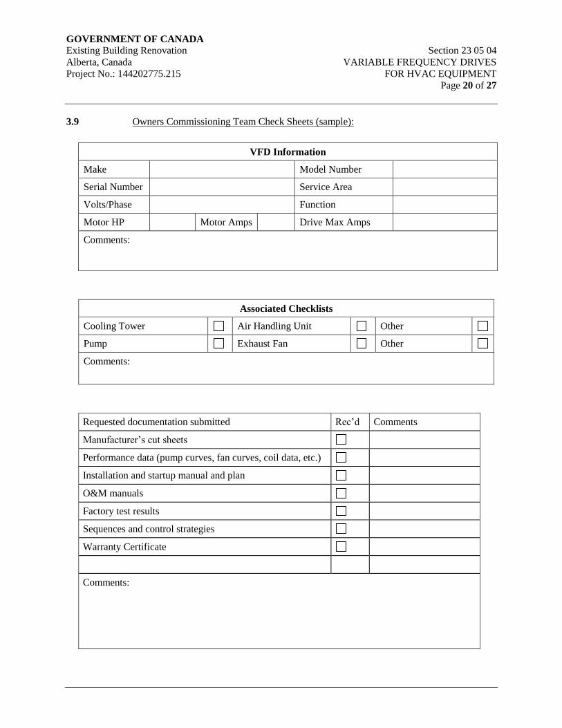
GOVERNMENT OF CANADA Existing Building Renovation Section 23 05 04
Alberta, Canada VARIABLE FREQUENCY DRIVES
Project No.: 144202775.215 FOR HVAC EQUIPMENT
Page 20 of 27
3.9 Owners Commissioning Team Check Sheets (sample):
Associated Checklists
Cooling Tower Air Handling Unit Other
Pump Exhaust Fan Other
Comments:
Requested documentation submitted Rec’d Comments
Manufacturer’s cut sheets
Performance data (pump curves, fan curves, coil data, etc.)
Installation and startup manual and plan
O&M manuals
Factory test results
Sequences and control strategies
Warranty Certificate
Comments:
VFD Information
Make Model Number
Serial Number Service Area
Volts/Phase Function
Motor HP Motor Amps Drive Max Amps
Comments:
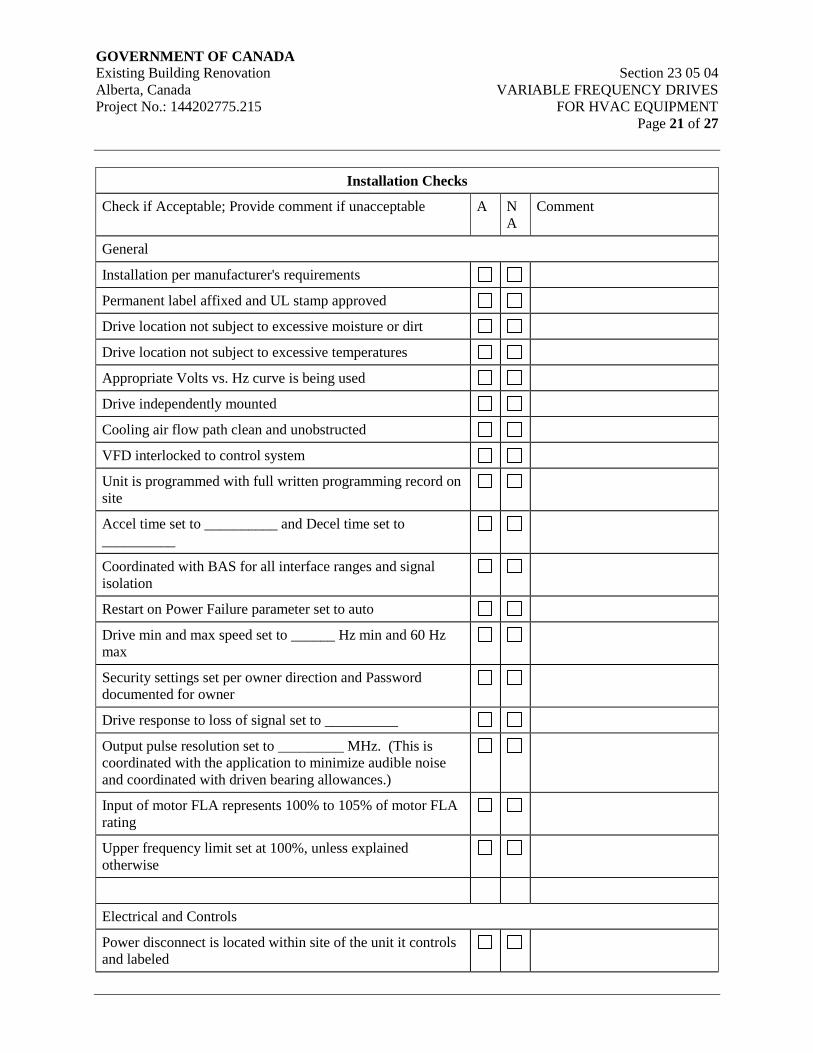
GOVERNMENT OF CANADA Existing Building Renovation Section 23 05 04
Alberta, Canada VARIABLE FREQUENCY DRIVES
Project No.: 144202775.215 FOR HVAC EQUIPMENT
Page 21 of 27
Installation Checks
Check if Acceptable; Provide comment if unacceptable A N
A
Comment
General
Installation per manufacturer's requirements
Permanent label affixed and UL stamp approved
Drive location not subject to excessive moisture or dirt
Drive location not subject to excessive temperatures
Appropriate Volts vs. Hz curve is being used
Drive independently mounted
Cooling air flow path clean and unobstructed
VFD interlocked to control system
Unit is programmed with full written programming record on
site
Accel time set to __________ and Decel time set to
__________
Coordinated with BAS for all interface ranges and signal
isolation
Restart on Power Failure parameter set to auto
Drive min and max speed set to ______ Hz min and 60 Hz
max
Security settings set per owner direction and Password
documented for owner
Drive response to loss of signal set to __________
Output pulse resolution set to _________ MHz. (This is
coordinated with the application to minimize audible noise
and coordinated with driven bearing allowances.)
Input of motor FLA represents 100% to 105% of motor FLA
rating
Upper frequency limit set at 100%, unless explained
otherwise
Electrical and Controls
Power disconnect is located within site of the unit it controls
and labeled
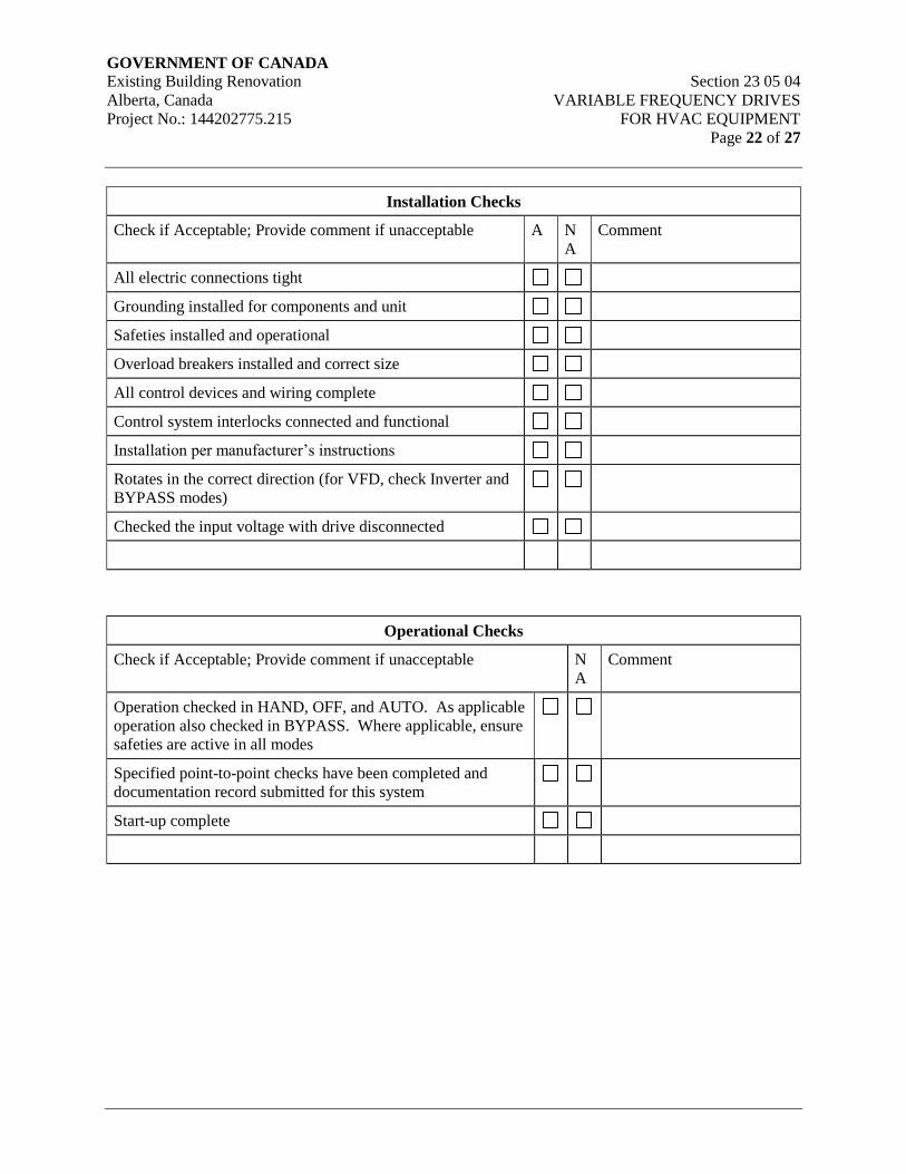
GOVERNMENT OF CANADA Existing Building Renovation Section 23 05 04
Alberta, Canada VARIABLE FREQUENCY DRIVES
Project No.: 144202775.215 FOR HVAC EQUIPMENT
Page 22 of 27
Installation Checks
Check if Acceptable; Provide comment if unacceptable A N
A
Comment
All electric connections tight
Grounding installed for components and unit
Safeties installed and operational
Overload breakers installed and correct size
All control devices and wiring complete
Control system interlocks connected and functional
Installation per manufacturer’s instructions
Rotates in the correct direction (for VFD, check Inverter and
BYPASS modes)
Checked the input voltage with drive disconnected
Operational Checks
Check if Acceptable; Provide comment if unacceptable N
A
Comment
Operation checked in HAND, OFF, and AUTO. As applicable
operation also checked in BYPASS. Where applicable, ensure
safeties are active in all modes
Specified point-to-point checks have been completed and
documentation record submitted for this system
Start-up complete
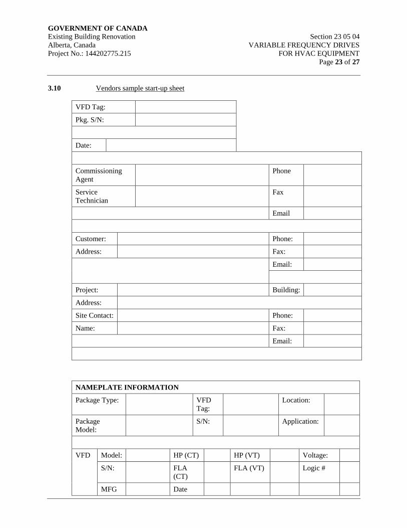
GOVERNMENT OF CANADA Existing Building Renovation Section 23 05 04
Alberta, Canada VARIABLE FREQUENCY DRIVES
Project No.: 144202775.215 FOR HVAC EQUIPMENT
Page 23 of 27
3.10 Vendors sample start-up sheet
VFD Tag:
Pkg. S/N:
Date:
Commissioning
Agent
Phone
Service
Technician
Fax
Customer: Phone:
Address: Fax:
Email:
Project: Building:
Address:
Site Contact: Phone:
Name: Fax:
Email:
NAMEPLATE INFORMATION
Package Type: VFD
Tag:
Location:
Package
Model:
S/N: Application:
VFD Model: HP (CT) HP (VT) Voltage:
S/N: FLA
(CT)
FLA (VT) Logic #
MFG Date
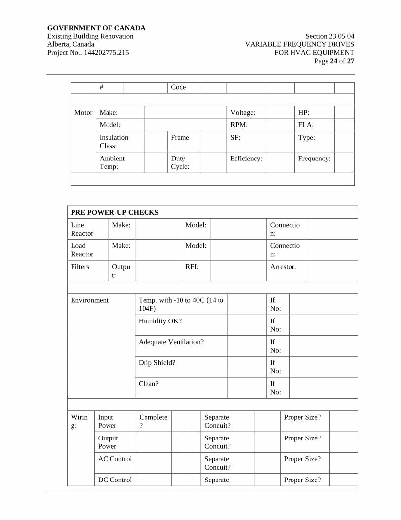
GOVERNMENT OF CANADA Existing Building Renovation Section 23 05 04
Alberta, Canada VARIABLE FREQUENCY DRIVES
Project No.: 144202775.215 FOR HVAC EQUIPMENT
Page 24 of 27
# Code
Motor Make: Voltage: HP:
Model: RPM: FLA:
Insulation
Class:
Frame SF: Type:
Ambient
Temp:
Duty
Cycle:
Efficiency: Frequency:
PRE POWER-UP CHECKS
Line
Reactor
Make: Model: Connectio
n:
Load
Reactor
Make: Model: Connectio
n:
Filters Outpu
t:
RFI: Arrestor:
Environment Temp. with -10 to 40C (14 to
104F)
If
No:
Humidity OK? If
No:
Adequate Ventilation? If
No:
Drip Shield? If
No:
Clean? If
No:
Wirin
g:
Input
Power
Complete
?
Separate
Conduit?
Proper Size?
Output
Power
Separate
Conduit?
Proper Size?
AC Control Separate
Conduit?
Proper Size?
DC Control Separate Proper Size?
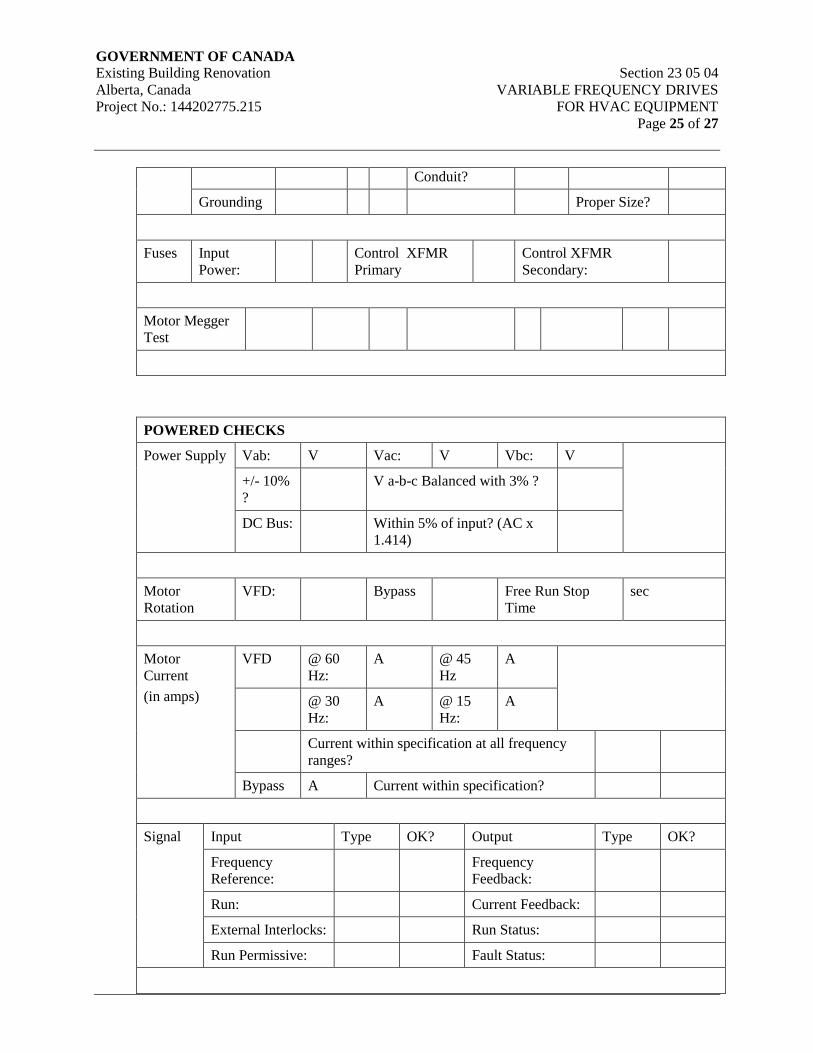
GOVERNMENT OF CANADA Existing Building Renovation Section 23 05 04
Alberta, Canada VARIABLE FREQUENCY DRIVES
Project No.: 144202775.215 FOR HVAC EQUIPMENT
Page 25 of 27
Conduit?
Grounding Proper Size?
Fuses Input
Power:
Control XFMR
Primary
Control XFMR
Secondary:
Motor Megger
Test
POWERED CHECKS
Power Supply Vab: V Vac: V Vbc: V
+/- 10%
?
V a-b-c Balanced with 3% ?
DC Bus: Within 5% of input? (AC x
1.414)
Motor
Rotation
VFD: Bypass Free Run Stop
Time
sec
Motor
Current
(in amps)
VFD @ 60
Hz:
A @ 45
Hz
A
@ 30
Hz:
A @ 15
Hz:
A
Current within specification at all frequency
ranges?
Bypass A Current within specification?
Signal Input Type OK? Output Type OK?
Frequency
Reference:
Frequency
Feedback:
Run: Current Feedback:
External Interlocks: Run Status:
Run Permissive: Fault Status:

GOVERNMENT OF CANADA Existing Building Renovation Section 23 05 04
Alberta, Canada VARIABLE FREQUENCY DRIVES
Project No.: 144202775.215 FOR HVAC EQUIPMENT
Page 26 of 27
Operator Bypass Module
Type:
Key Pad Type: Speed
Pot
Switches VFD-Off-Bypass Hand-Off-Auto (Other)
Lights Power: Hand: Auto: Run:
VFD: Bypass: At
Speed:
Fault:
Keypad
Lit
Ext.
Fault:
AUXILLIARY ITEMS / OPTIONS (e.g. PUMPS STARTERS; PAN HEATERS)
Option Type #1: Option Type #2:
Voltage: Voltage:
HP / kW: HP / kW:
Fuses / Size: Fuses / Size:
Sel. Sw. Sel. Sw.
Pilot Light(s) Pilot Light(s)
Functions per
Dwg?
Functions per
Dwg?
Measure Amps: Measure Amps:
Other Comments: Other Comments:
External PID Controller Parameter Settings per
Attached
Network Communications
Network Type (e.g. N2, FLN,
BACnet)
Model / Type of Interface:
Address:
General
Parameters recorded and attached? If no,
why?
Parameters saved to laptop? File
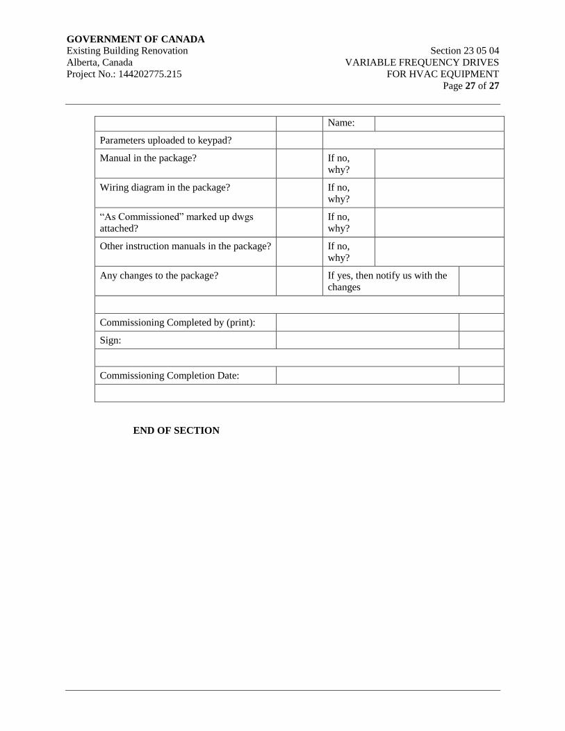
GOVERNMENT OF CANADA Existing Building Renovation Section 23 05 04
Alberta, Canada VARIABLE FREQUENCY DRIVES
Project No.: 144202775.215 FOR HVAC EQUIPMENT
Page 27 of 27
Name:
Parameters uploaded to keypad?
Manual in the package? If no,
why?
Wiring diagram in the package? If no,
why?
“As Commissioned” marked up dwgs
attached?
If no,
why?
Other instruction manuals in the package? If no,
why?
Any changes to the package? If yes, then notify us with the
changes
Commissioning Completed by (print):
Sign:
Commissioning Completion Date:
END OF SECTION
GOVERNMENT OF CANADA Existing Building Renovation Section 23 05 13
Alberta, Canada COMMON MOTOR REQUIREMENTS
Project No.: 144202775.215 FOR HVAC EQUIPMENT
Page 1 of 8
1. General
1.1 Scope
.1 This section covers general motor requirements for factory and field installed motors.
.2 Refer to individual sections for application of motors and reference to specific motor
requirements for motor driven equipment.
.3 Motors shall be suitable for horizontal, vertical or belt driven mounting.
1.2 Submittals
.1 Submit shop drawings for motor driven equipment, as required by equipment
specification sections. Motor shop drawing information shall include, but not be limited
to the following:
.1 Voltage/Phase./Hertz
.2 Motor power (kW or Watts)
.3 Full load amps
.4 Wiring diagrams (as required)
1.3 Delivery, Storage & Handling
.1 Deliver and store materials in accordance with Section 23 05 00 – Common Work
Results for HVAC.
1.4 Waste Management and Disposal
.1 Separate waste materials for reuse and recycling in accordance with Section 23 05 00 –
Common Work Results for HVAC .
1.5 Related Work Specified in Other Sections
.1 Refer to and comply with the following sections:
.1 General Service Packaged Air Compressors & Receivers Section 22 15 19
.2 Common Work Results for HVAC Section 23 05 00
.3 Variable Frequency Drives Section 23 05 04
.4 HVAC Fans Section 23 34 00
.5 Packaged Indirect Fired Make-Up Air Units Section 23 74 23.16
.6 Electrical Division 26
GOVERNMENT OF CANADA Existing Building Renovation Section 23 05 13
Alberta, Canada COMMON MOTOR REQUIREMENTS
Project No.: 144202775.215 FOR HVAC EQUIPMENT
Page 2 of 8
1.6 Standards
.1 Provide motors designed, manufactured, and tested in accordance with the latest edition
of the following codes and standards:
.1 National Electrical Manufacturers Association (NEMA)
.2 Electrical Equipment Manufacturers Association of Canada (EEMAC)
.3 Canadian Standards Association (CSA)
.4 Canadian Electrical Code (CEC) Part 1
.5 Institute of Electrical and Electronic Engineers (IEEE)
.6 American National Standards Institute (ANSI)
1.7 Quality Assurance
.1 All motors shall be ULC listed and CSA certified.
.2 All motors to be approved for use in the designated area classification by the Electrical
Protection Branch, Alberta Department of Labor.
.3 Full Voltage Start Applications:
.1 All motors shall be in accordance with NEMA standards, and CSA C390-93, or
the latest version insofar as it is applicable. Motors also shall comply with the
applicable portions of the Canadian Electrical Code.
.4 Variable Frequency Drive and Soft Start Applications:
.1 Where equipment is noted to be controlled by a VFD on the equipment
schedules, or in other Sections, the motors shall be in accordance with NEMA
standards (MG-1) Part 31, and inverter duty class, or the latest version insofar as
it is applicable. Motors also shall comply with the applicable portions of the
Canadian Electrical Code.
.2 Motors connected to VFD(s) shall be wound using inverter spike resistant
magnet wire capable of 1600V.
1.8 Testing
.1 Production Tests: Each motor shall receive a routine commercial test per NEMA MG-
1.12. Prototype test reports shall be for each rating.
.2 Sound Level: The noise level of each motor shall comply with NEMA MG-1.12.49.
.3 Vibration Level: The vibration level of each motor shall not exceed those values listed in
NEMA MG-1.12.05.
GOVERNMENT OF CANADA Existing Building Renovation Section 23 05 13
Alberta, Canada COMMON MOTOR REQUIREMENTS
Project No.: 144202775.215 FOR HVAC EQUIPMENT
Page 3 of 8
1.9 Variable Speed Drives
.1 Motors shall be designed for operation with Variable Frequency Drives as noted on the
motor schedule.
2. Products
2.1 General Requirements
.1 Provide motors for mechanical equipment as specified.
.2 Unless noted otherwise, provide open drip-proof, ball or roller bearing motors with
grease fittings.
.3 Motors shall have standard voltage ratings consistent with the project distribution
voltages.
.1 Motors 0.372 kW (½ HP) and less to be 120 volt, 60 cycle, single-phase power.
.2 Motors 0.559 kW (¾ HP) and larger to be 3 phase power and for the scheduled
voltage.
.3 Confirm electric voltage, phase and starter requirements with the electrical
specifications.
.4 Refer to equipment schedules on drawings.
.4 Provide motors with grease or oil lubricated anti-friction type ball or roller bearings.
.5 Provide motors designed with Class B insulation; Class F insulation for totally enclosed
motors.
.6 Provide all motors with terminal boxes, suitable for power connections.
.7 Provide screw adjustable bases on all belt-connected motors.
.8 Motors shall be of the capacitor start type when they may be manually cycled from a
starting switch which is located in the finished space.
.9 Motors exposed to outdoor temperature to be lubricated with lubricants suitable for
operation at 6°C below the lowest temperature recorded by ASHRAE or the Climatic
Information (Supplement to the National Building Code), for the location in which they
are installed.
.10 Refer to electrical specifications for voltage, frequency, and phase data. This shall take
precedence over any reference in Division 23. Packaged equipment shall have
connections as specified in Division 26.
.11 Where motor power is stated in watts or kilowatts, nominal motor horsepower multiplied
by 746 or 0.746 respectively, has been used as the conversion factor.
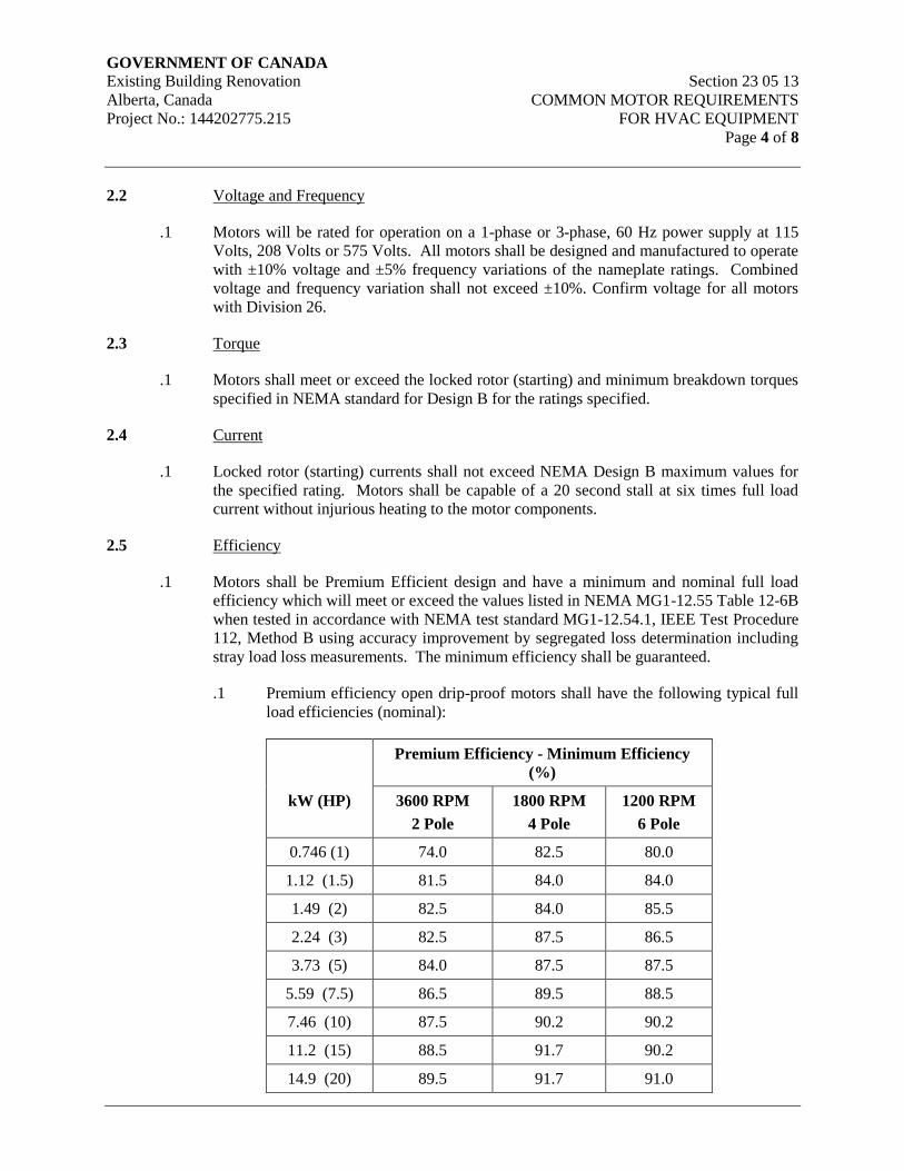
GOVERNMENT OF CANADA Existing Building Renovation Section 23 05 13
Alberta, Canada COMMON MOTOR REQUIREMENTS
Project No.: 144202775.215 FOR HVAC EQUIPMENT
Page 4 of 8
2.2 Voltage and Frequency
.1 Motors will be rated for operation on a 1-phase or 3-phase, 60 Hz power supply at 115
Volts, 208 Volts or 575 Volts. All motors shall be designed and manufactured to operate
with ±10% voltage and ±5% frequency variations of the nameplate ratings. Combined
voltage and frequency variation shall not exceed ±10%. Confirm voltage for all motors
with Division 26.
2.3 Torque
.1 Motors shall meet or exceed the locked rotor (starting) and minimum breakdown torques
specified in NEMA standard for Design B for the ratings specified.
2.4 Current
.1 Locked rotor (starting) currents shall not exceed NEMA Design B maximum values for
the specified rating. Motors shall be capable of a 20 second stall at six times full load
current without injurious heating to the motor components.
2.5 Efficiency
.1 Motors shall be Premium Efficient design and have a minimum and nominal full load
efficiency which will meet or exceed the values listed in NEMA MG1-12.55 Table 12-6B
when tested in accordance with NEMA test standard MG1-12.54.1, IEEE Test Procedure
112, Method B using accuracy improvement by segregated loss determination including
stray load loss measurements. The minimum efficiency shall be guaranteed.
.1 Premium efficiency open drip-proof motors shall have the following typical full
load efficiencies (nominal):
Premium Efficiency - Minimum Efficiency
(%)
kW (HP) 3600 RPM
2 Pole
1800 RPM
4 Pole
1200 RPM
6 Pole
0.746 (1) 74.0 82.5 80.0
1.12 (1.5) 81.5 84.0 84.0
1.49 (2) 82.5 84.0 85.5
2.24 (3) 82.5 87.5 86.5
3.73 (5) 84.0 87.5 87.5
5.59 (7.5) 86.5 89.5 88.5
7.46 (10) 87.5 90.2 90.2
11.2 (15) 88.5 91.7 90.2
14.9 (20) 89.5 91.7 91.0
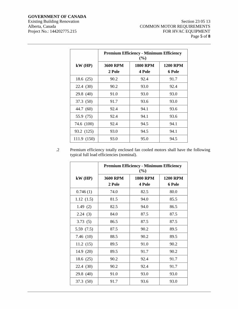
GOVERNMENT OF CANADA Existing Building Renovation Section 23 05 13
Alberta, Canada COMMON MOTOR REQUIREMENTS
Project No.: 144202775.215 FOR HVAC EQUIPMENT
Page 5 of 8
Premium Efficiency - Minimum Efficiency
(%)
kW (HP) 3600 RPM
2 Pole
1800 RPM
4 Pole
1200 RPM
6 Pole
18.6 (25) 90.2 92.4 91.7
22.4 (30) 90.2 93.0 92.4
29.8 (40) 91.0 93.0 93.0
37.3 (50) 91.7 93.6 93.0
44.7 (60) 92.4 94.1 93.6
55.9 (75) 92.4 94.1 93.6
74.6 (100) 92.4 94.5 94.1
93.2 (125) 93.0 94.5 94.1
111.9 (150) 93.0 95.0 94.5
.2 Premium efficiency totally enclosed fan cooled motors shall have the following
typical full load efficiencies (nominal).
Premium Efficiency - Minimum Efficiency
(%)
kW (HP) 3600 RPM
2 Pole
1800 RPM
4 Pole
1200 RPM
6 Pole
0.746 (1) 74.0 82.5 80.0
1.12 (1.5) 81.5 94.0 85.5
1.49 (2) 82.5 94.0 86.5
2.24 (3) 84.0 87.5 87.5
3.73 (5) 86.5 87.5 87.5
5.59 (7.5) 87.5 90.2 89.5
7.46 (10) 88.5 90.2 89.5
11.2 (15) 89.5 91.0 90.2
14.9 (20) 89.5 91.7 90.2
18.6 (25) 90.2 92.4 91.7
22.4 (30) 90.2 92.4 91.7
29.8 (40) 91.0 93.0 93.0
37.3 (50) 91.7 93.6 93.0
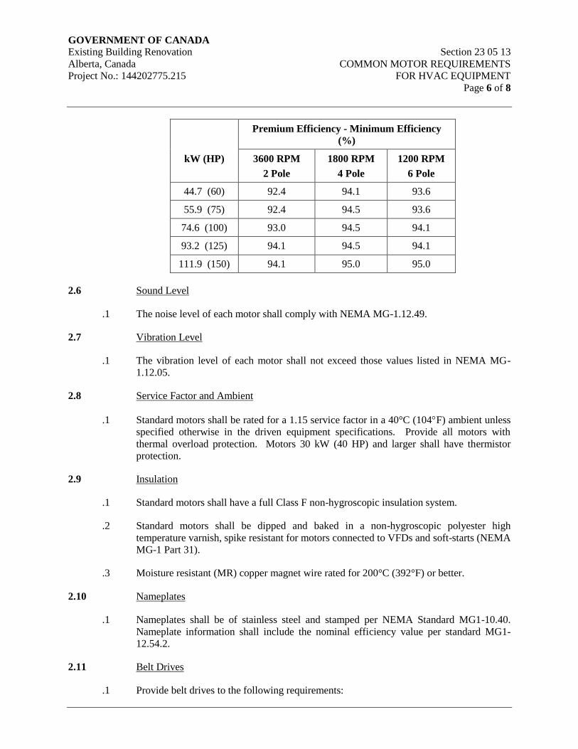
GOVERNMENT OF CANADA Existing Building Renovation Section 23 05 13
Alberta, Canada COMMON MOTOR REQUIREMENTS
Project No.: 144202775.215 FOR HVAC EQUIPMENT
Page 6 of 8
Premium Efficiency - Minimum Efficiency
(%)
kW (HP) 3600 RPM
2 Pole
1800 RPM
4 Pole
1200 RPM
6 Pole
44.7 (60) 92.4 94.1 93.6
55.9 (75) 92.4 94.5 93.6
74.6 (100) 93.0 94.5 94.1
93.2 (125) 94.1 94.5 94.1
111.9 (150) 94.1 95.0 95.0
2.6 Sound Level
.1 The noise level of each motor shall comply with NEMA MG-1.12.49.
2.7 Vibration Level
.1 The vibration level of each motor shall not exceed those values listed in NEMA MG-
1.12.05.
2.8 Service Factor and Ambient
.1 Standard motors shall be rated for a 1.15 service factor in a 40°C (104F) ambient unless
specified otherwise in the driven equipment specifications. Provide all motors with
thermal overload protection. Motors 30 kW (40 HP) and larger shall have thermistor
protection.
2.9 Insulation
.1 Standard motors shall have a full Class F non-hygroscopic insulation system.
.2 Standard motors shall be dipped and baked in a non-hygroscopic polyester high
temperature varnish, spike resistant for motors connected to VFDs and soft-starts (NEMA
MG-1 Part 31).
.3 Moisture resistant (MR) copper magnet wire rated for 200°C (392°F) or better.
2.10 Nameplates
.1 Nameplates shall be of stainless steel and stamped per NEMA Standard MG1-10.40.
Nameplate information shall include the nominal efficiency value per standard MG1-
12.54.2.
2.11 Belt Drives
.1 Provide belt drives to the following requirements:
GOVERNMENT OF CANADA Existing Building Renovation Section 23 05 13
Alberta, Canada COMMON MOTOR REQUIREMENTS
Project No.: 144202775.215 FOR HVAC EQUIPMENT
Page 7 of 8
.1 Provide steel, cast iron or aluminum sheaves for motors less than 0.559 kW (3/4
HP).
.2 Provide steel or cast iron sheaves keyed to shafts, for motors 0.559 kW (3/4 HP)
and larger.
.3 For motors less than 7.46 kW (10 HP) provide standard adjustable pitch drive
sheaves having +/-10% range. Use mid-position of range for specified RPM.
.4 For motors 7.46 kW (10 HP) and larger, provide fixed pitch drive sheaves with
split tapered bushing and keyway. Provide final drive sheaves of size to suit final
balancing.
.2 Match drive and driven sheaves.
.3 V-belts shall conform to the American Belt Manufacturers standards. Multiple belts shall
be matched sets.
.4 Not less than a 2-belt configuration is required for each drive for motors 0.559 kW (3/4
HP) and larger.
3. Execution
3.1 General
.1 Unless otherwise noted starters and protection devices will be included under the
Electrical Division of the Specification.
.2 Assist Division 26 to ensure proper connection, correct thermal overload protection and
correct motor controls.
.3 Where starters are included in this Division as an integral part of packaged equipment,
they shall contain thermal overload protection in all ungrounded lines.
.4 Equipment, which has more than one voltage rating, shall be fed from a single power
source through a disconnect switch.
.5 If delivery of specified motor will delay delivery or installation of any equipment, install
an acceptable motor for temporary use. Final acceptance of equipment will not be given
until specified motor is installed.
3.2 Setting and Alignment
.1 Employ a journeyman millwright to align all V-belt drives and/or shaft coupling drives
prior to initial start-up. The millwright shall also check that centrifugal fan wheels are
properly centered on fan shafts.
.2 Align shaft couplings, using a dial indicator, to within +/-0.051 mm (0.002") after
grouting is complete and the piping system is operational.

GOVERNMENT OF CANADA Existing Building Renovation Section 23 05 13
Alberta, Canada COMMON MOTOR REQUIREMENTS
Project No.: 144202775.215 FOR HVAC EQUIPMENT
Page 8 of 8
.3 Align V-belt drives using a straight edge.
.4 Submit a certificate from the millwright employed, certifying that all shaft couplings and
V-belt drives have been aligned and centrifugal fan wheels centered prior to initial start-
up and checked again after final system balance adjustment.
END OF SECTION

GOVERNMENT OF CANADA Existing Building Renovation Section 23 05 14
Alberta, Canada VARIABLE FREQUENCY DRIVES
Project No.: 144202775.215 FOR HVAC EQUIPMENT
Page 1 of 27
1. General
1.1 Scope
.1 This section includes the supply, installation, start-up, testing and commissioning for
variable frequency drives (VFD) controllers, including but not limited to: associated
enclosures, input and output filters, warranty, local and remote control.
.2 The VFD and all specified components, including internal wiring between those
components, must be installed and integrated into one common enclosure, supplied,
factory tested, and commissioned by the VFD supplier. The integrated VFD assembly
shall be ready for filed installation and require only the connection of the incoming power
cables, the motor load cables, and the control wiring for start-up, and the commissioning
of the VFDs.
.3 The VFD supplier must coordinate with the installation contractor with respect to
delivery dates, technical support for the installation, equipment start-up, and the
commissioning of the VFDs.
.4 All drives and ancillary components specified in this section to be supplied by one
manufacturer to assure a properly coordinated system.
.5 Design all equipment using modularized solid state equipment to allow easy maintenance
and replacement.
1.2 Submittals
.1 Comply with the requirements of Section 23 05 00 – Common Work Results for HVAC.
.2 Provide the following shop drawing information:
.1 Catalog and technical data.
.2 Outline dimensions, shipping section dimensions, weight, and foundation
requirements for all assemblies.
.3 Physical details of the cabinets, a wiring diagram, and a ladder diagram showing
both internal connections and terminals for field wiring, showing function and
identification of all terminals requiring field connections. Separate diagrams are
required for each VFD size. Generic diagrams are not acceptable.
.4 Component fabrication drawings consisting of detailed circuit schematics,
indicating all components in the VFD package, including line and load reactor
impedance ratings and/or filter design type, VFD current, HP and voltage rating.
.5 Bolt and lug torque schedule for all power and control wiring termination points.
.6 Vendor’s start-up sheets for the drive.

GOVERNMENT OF CANADA Existing Building Renovation Section 23 05 14
Alberta, Canada VARIABLE FREQUENCY DRIVES
Project No.: 144202775.215 FOR HVAC EQUIPMENT
Page 2 of 27
.3 Upon delivery, provide as-built shop drawings for each unit. A copy of the as-built shop
drawings shall be provided for each drive in addition to one set of drawings for each copy
of the O&M Manuals. (See info in the project specifications and drawings for quantities
in addition to that indicated herein, the quantities shall be the maximum indicated plus 1
copy for each drive).
.4 Supply four (4) copies of Operation and Maintenance manual containing data for each
VFD. Data shall include:
.1 Troubleshooting charts for all device faults.
.2 An instruction manual for: programming and the hardware provided with the
equipment at time of shipment.
.3 Manufacturer’s start-up check sheet(s) with list(s) that outline all of the
completed tasks. Check-sheets are to contain actual start-up data and shall list all
settings and parameters present in the drive unit as commissioned.
.4 VFD field-test measurement results. All data provided shall be that from the last
testing conducted on the drive. If original testing was redone, then the new data
shall be provided in addition to the original data Original tests must then be
marked “Superseded. For Information Only”. All test data shall be dated and
signed".
.5 Settings sheets to record all VFD configuration options and selections for VFD
set-up. Settings sheets are to contain actual start-up data and shall list all settings
and parameters present in the drive unit as commissioned.
.6 Include a list of authorized recommended spare parts, service depots, spare parts
list.
.5 Provide copies of the VFD programming / troubleshooting software, as well as any
connection cables required, to Owner. Provide one set of software and cabling, for each
size of drive, for each O&M manual provided.
1.3 Delivery & Storage
.1 Deliver and store materials in accordance with Section 23 05 00 – Common Work
Results for HVAC.
1.4 Waste Management and Disposal
.1 Separate waste materials for reuse and recycling in accordance with Section 23 05 00 –
Common Work Results for HVAC.
1.5 Related work specified in other sections
.1 Common Work Results for HVAC Section 23 05 00
.2 Common Motor Requirements for HVAC Equipment Section 23 05 13
GOVERNMENT OF CANADA Existing Building Renovation Section 23 05 14
Alberta, Canada VARIABLE FREQUENCY DRIVES
Project No.: 144202775.215 FOR HVAC EQUIPMENT
Page 3 of 27
.3 Testing, Adjusting and Balancing for HVAC Systems Section 23 05 93
.4 Electrical Division 26
1.6 Standards
.1 VFD units shall be ULC listed and CSA (or cUL) certified.
.2 VFD units shall comply with applicable requirements of the latest standards of CSA,
ANSI, IEEE 519, NEMA MG1 and the Canadian Electrical Code.
1.7 Intended operation
.1 The VFD shall be designed to operate standard squirrel cage induction motors with a 1.0
service factor meeting NEMA MG1 Part 31. Refer to Section 23 05 13 – Common Motor
Requirements for HVAC Equipment.
.2 The VFDs shall control one of more fan motor(s) or pump motor(s) as listed in the
drawing schedules.
.3 The VFD shall communicate with, and be controlled by, the building automation system
(BAS) which will provide Run Command and an Operating Speed reference to the VFD.
VFD Run Status, Operating Speed, Load Amps, Power and Alarm or Fault data shall be
communicated back to the BAS. The VFD shall also be capable of operating in PID
Mode with the Run Command and PID Set Point communicated by the BAS. A process
monitoring transmitter (supplied by the controls contractor) will be connected directly to
the VFD. Refer to Controls, Sections 23 09 Series.
.4 Communication with the BMS shall be BACnet MSTP over EIA-485.
1.8 Factory Testing
.1 Prior to shipment, all VFD units are to be shop-tested at the factor or at the VFDs
OEM/integrator’s facilities. Testing shall include, but will not be limited to, a complete
functional test to fully prove out the VFD and all the local and remote control functions
and required parameter settings. Phase-loss protection for each of the 3 phases of the
VFD shall be proven as part of the factory testing.
.2 Provide factory-certified copies of production test results to the Engineer prior to
shipment of the equipment.
1.9 Harmonic Guidelines
.1 All VFD installations shall meet IEEE-519-1992 harmonic guidelines.
.2 Following award of contract, and prior to submitting shop drawings, the VFD vendor
shall review the electrical system design and MCC locations and advise if filtering, in
addition to the specified line reactors, is required.
GOVERNMENT OF CANADA Existing Building Renovation Section 23 05 14
Alberta, Canada VARIABLE FREQUENCY DRIVES
Project No.: 144202775.215 FOR HVAC EQUIPMENT
Page 4 of 27
1.10 Warranty
.1 The VFD supplier shall provide warranty coverage for a minimum period of twelve (12)
months commencing upon the date of substantial completion. Refer to Division 0 and
Division 1.
.2 The Vendor shall be responsible to bring a Factory Representative back to reset, repair,
and re-commission the VFD if problems arise with the normal operation of that VFD
during the warranty period.
1.11 Maintenance
.1 VFD supplier is to include a preventative maintenance program (PMP) for a one year
period. The PMP is to be broken down to daily, weekly, monthly and annual service
periods. Each service period is to include all manufacturer recommended maintenance
tasks which should be completed in each period. A maintenance checklist is to be cross
referenced to the maintenance period and maintenance task.
1.12 Training
.1 Provide an on-site, half day training seminar for maintenance and service personnel.
.2 The VFD supplier shall detail an agenda for the training to be provided and to present it
to the Engineer for review and adjustment. Refer to Section 23 05 00 – Common Work
Results for HVAC.
.3 The Vendor shall comply with the Engineers requests for modification of the content to
suit its needs within the four (4) hour time allowance. The training agenda shall be
provided four (4) weeks prior to the drive start-up, and the VFD Supplier shall schedule
the timing & location of the seminar at a time and location suitable to the Engineer.
.4 Refer to and comply with Section 23 05 00 – Common Work Results for HVAC.
2. Products
2.1 Section Includes:
.1 Approved VFD Suppliers and Product
.2 Vendor Requirements – Service and Support
.3 General VFD Requirements
.4 Environmental Capabilities
.5 Input Power
.6 Output Power
.7 Equipment Protection
GOVERNMENT OF CANADA Existing Building Renovation Section 23 05 14
Alberta, Canada VARIABLE FREQUENCY DRIVES
Project No.: 144202775.215 FOR HVAC EQUIPMENT
Page 5 of 27
.8 Approved Filter Manufacturers
.9 Integrated VFD Equipment Enclosure
.10 BACnet
.11 PID Control
.12 Control and Operational Features
.13 Drive Control (Hand operation)
.14 Drive Controls (Auto Operation)
.15 Isolated Bypass Operation
.16 Drive Parameter Settings
.17 Diagnostics
.18 Drives Connected to Emergency Power System
.19 Wiring and Identification
2.2 Acceptable Products
.1 Variable Frequency Drive (VFD) as supplied by:
.1 ABB
.2 Cutler Hammer
.3 Danfoss
.4 General Electric
.5 Siemens
.6 TECO-Westinghouse
.7 Mistubishi (MGI)
2.3 vendor requirements – Service and Support
.1 The drive vendor must provide a factory-trained sales force locally available for
applications assistance and to answer maintenance questions.
.2 The vendor must have a distributor organization, which locally stocks standard drives,
modification kits, and spare parts.
GOVERNMENT OF CANADA Existing Building Renovation Section 23 05 14
Alberta, Canada VARIABLE FREQUENCY DRIVES
Project No.: 144202775.215 FOR HVAC EQUIPMENT
Page 6 of 27
.3 The vendor must have factory-trained service representatives within the local Edmonton
area. The factory representatives must be trained in the maintenance and troubleshooting
of the equipment as specified herein.
.4 Vendor must provide regularly scheduled maintenance and training schools in Canada on
the equipment supplied
2.4 General VFD Requirements
.1 All units shall be ULc or CSA approved.
.2 VFD unit shall comply with applicable requirements of the latest standards of CSA,
ANSI, IEEE, NEMA, and the Canadian Electrical Code.
.3 Unless otherwise noted, all horsepower/kW ratings are to be based on a Variable Torque
load.
.4 VFD shall be provided with a CSA (NEMA) Type 1 enclosure.
.5 The VFD shall be rated for continuous duty while operating a NEMA design induction
motor of the sizes and operating voltages as shown in the applicable schedules and
indicated on the drawings.
.6 The VFDs shall have a current rating at least 10% in excess of the motor full load amp
rating. When subject to the range of ambient conditions, the VFD to be capable of
delivering 110% of rated output current for up to one minute for variable torque loads
.7 The VFD shall have a fixed bridge type converter (PWM) utilizing Insulated Gate
Bipolar Transistor (IGBT) technology.
.8 VFD operation to be fully digital with microprocessor control of frequency, voltage, and
current.
.9 Efficiency of VFD controller shall not be less than 97.5% at 60 Hz output at 100% rated
load.
2.5 Environmental Capabilities
.1 The drive shall operate without mechanical or electrical damage under any combination
of conditions as follows:
.1 Ambient temperature: 0 to 40C (32F to 105F)
.2 Humidity: 5 to 95% (non condensing)
.3 Vibration: up to 0.5 G

GOVERNMENT OF CANADA Existing Building Renovation Section 23 05 14
Alberta, Canada VARIABLE FREQUENCY DRIVES
Project No.: 144202775.215 FOR HVAC EQUIPMENT
Page 7 of 27
.4 Altitude: 0 to 1200m (0 ft to 3940 ft); For altitudes above 1200m (3960 ft), the
equipment must be properly de-rated such that the higher altitude rating is greater
than the required output.
.5 The VFD unit may require fan-assisted cooling to ensure adequate heat
dissipation. Such a system shall be installed in a manner that does not degrade
the enclosure rating. Provide alarm status and shut-down for the VFD, on
excessive temperature rise in the enclosure, for VFDs that utilize forced air fans
for enclosure cooling.
2.6 Input Power
.1 Input voltage shall be as indicated on motor schedules and drawings, line voltage
variation (10%), 3 phase, 60 Hz, grounded power supply without high or low line
tripping. Confirm voltage before ordering.
.2 The VFD must be capable of operating under the following conditions without high or
low line tripping: 3 phase, 60Hz, alternating current, grounded power supply, line voltage
as shown (240,480, 600) ±10%. Speed stability shall be ±1%.
.3 Permit power line interruptions for high inertia loads such as fans and centrifuges for at
least 2.0 seconds without the VFD shutting down on a fault providing an extended power
loss ride-through. If the drive trips on undervoltage, the drive will activate the Automatic
Restart. See “Rotating Start” clause 2.13.17.
.4 The VFD shall present a displacement power factor of 0.98 or better to the AC line over
10% to 100% speed range. Full load effective power factor shall be 96% or better.
.5 The VFD must operate satisfactorily when connected to a bus supplying other solid state
power conversion equipment which may be causing up to 5% total harmonic voltage
distortion and communication notches up to 36,500 volt microseconds.
.6 Normal power distribution is subject to voltage surges and sags as a normal condition of
operation. Design and supply with each VFD the required inverter protection such that
the VFD will not be stressed or damaged, in the following conditions:
.1 Line surges of up to 115% of rated voltage for up to 10 cycles. Based on
347/600 Volt systems.
.2 Line voltage sags down to 85% of rated voltage of up to 1 second duration.
.7 Provide a 5% impedance line reactor at in the drive input to protect electronic
components from transient voltage conditions and to reduce harmonic current distortion.
.8 The VFD must not be sensitive to supplied power that has one phase grounded (Delta –
with balanced voltages) or referenced to earth ground (Wye).
.9 The VFD must not be sensitive to incoming phase sequence.
GOVERNMENT OF CANADA Existing Building Renovation Section 23 05 14
Alberta, Canada VARIABLE FREQUENCY DRIVES
Project No.: 144202775.215 FOR HVAC EQUIPMENT
Page 8 of 27
.10 VFDs shall be of the 6-pulse PWM- type complete with an external AC line reactor to
reduce harmonic current distortion.
2.7 Output Power
.1 The VFD shall produce a 3 phase output for motor loads.
.2 Pulse-Width Modulating (PWM) circuitry must consist of a full wave diode bridge
converter to convert incoming fixed voltage and frequency to a fixed DC voltage. The
Pulse Width Modulation strategy shall incorporate a microprocessor to handle all Logic
functions as well as the complex, sine-coded PWM generating algorithms that control
output stage switching.
.3 Generate the inverter output by IGBT power transistors only.
.4 The VFD output waveform to be the PWM or Vector type waveform producing smooth
torque at low frequencies and low motor current harmonics.
.5 Harmonic loading shall not exceed the maximums acceptable for motor operation with a
service factor of 1.0.
.6 The VFD output voltage shall be user-adjustable to deliver voltage from 0 V to full
voltage at 60 Hz.
.7 The VFD shall be provided with user-adjustable settings to provide a frequency range of
0 to 120 Hz.
.8 Unless otherwise specified, the VFD output voltage to be adjustable from 0 to full
voltage reaching full voltage at 60 Hz.
.9 Provide selectable constant V/Hz ratio PWM or variable V/Hz for Variable Torque loads.
.10 The VFD must maintain capability for 100% of rated output current continuously,
regardless of change in ambient conditions throughout its listed ambient conditions range.
.11 PWM carrier frequency shall be user-selectable.
.12 Manufacturer to indicate, at time of tender, the anticipated levels of electrical noise and
heat generated. In any case, the Audible noise levels to be less than 85 dbA at 1 m out
from any point on the VFD cabinet under normal operating condition, with the drive at
full load.
.13 Radio Frequency Interference (RFI) must be limited to levels specified in applicable
standards. Equipment must be designed that use of radio communication equipment
adjacent to VFD units is permissible. In addition, the VFD must not be susceptible to
interference from radio equipment operated adjacent to it.
GOVERNMENT OF CANADA Existing Building Renovation Section 23 05 14
Alberta, Canada VARIABLE FREQUENCY DRIVES
Project No.: 144202775.215 FOR HVAC EQUIPMENT
Page 9 of 27
2.8 Equipment Protection
.1 Protective devices to be incorporated are:
.1 Three-pole fused disconnect switch to provide over-current protection with fuses
rated at not more than 150% of drive input current rating, except if the VFD is
specifically marked with a recommended rating for its over-current protection,
then the VFD marking shall take precedence.
.2 The operation of the disconnect switch shall be interlocked with the VFD
enclosure door. It shall not be possible to open the door without the disconnect
being in the open position. A manual means to defeat this interlock for
maintenance purposes shall be included, and the external operator handle for the
switch must have lock-out capability.
.3 The symmetrical short-circuit interrupting rating shall be verified for every
installation, and be coordinated with the VFDs electronic protection circuits.
VFD supplier is responsible to obtain SSCIR information from the designer or
design documents for the VFDs being constructed for the project.
.4 Integral electronic motor overload protection adjustable up to 150% of motor
rating for 60 seconds.
.5 Ground fault protection.
.6 Over-voltage/over-current DC bus monitor/protection.
.7 Under-voltage protection, 85% of rated input voltage.
.8 Loss of phase and phase unbalance protection.
.9 Inverter over-temperature protection.
.10 Motor overload protection, adjustable 80 to 115% of FLA of motor.
.11 Where bypass contactors are utilized or where the VFD serves several motors,
provide external dial adjustable motor overload protection relays with inherent
single-phase protection. The current range of the overload block shall be selected
to place the full-load current of the motor at approximately the centre of the dial
scale for the supplied overload relay.
.2 Include provision for adequate grounding within the equipment in addition to that
provided to safeguard against electrostatic discharge damage.
2.9 Approved Filter Manufacturers
.1 All applications with non-VFD or VFD rated motors shall require output dv/dt filters.
The following manufacturers of filters are acceptable.

GOVERNMENT OF CANADA Existing Building Renovation Section 23 05 14
Alberta, Canada VARIABLE FREQUENCY DRIVES
Project No.: 144202775.215 FOR HVAC EQUIPMENT
Page 10 of 27
.1 TCI
.2 MTE
2.10 Integrated VFD Equipment Enclosure
.1 The integrated VFD assembly, including all components shall be provided as a ventilated
CSA (NEMA) Type 1 enclosure, with a hinged, gasketed door and a drip-shield
constructed to project over the door and sized to protect all ventilation openings in the top
of the enclosure (if any) from dripping water. It shall be suitable for wall or free-standing
installation.
.2 Supply full-length painted 100mm steel channels for floor-mounted VFD enclosures.
.3 Where house-keeping pads are provided, the channel bases are not required. Where a
drive is placed on top of a housekeeping pad, base construction shall be such that the
door of the VFD will not drag on the house-keeping pad.
.4 Forced air cooled enclosures shall have filters on all air inlet openings.
.5 The backspan to be galvanized metal, non-painted, 16 gauge for EMC bonding
requirements. Provide a minimum of 2 lugs for bonding conductors (sized per CEC).
Lugs shall be bolted to the galvanized metal back-pan.
.6 Door shall be grounded with multi-conductor or braided ground strap connecting the door
to the grounding system in the enclosure interior.
2.11 BACnet
.1 The VFD shall communicate with a building automation system (BAS) network by
digital communication using the BACnet MSTP protocol (ANSI/ASHRAE Standard 135-
2004) over EIA-485.
2.12 PID Control
.1 Provide process controller circuitry incorporating a PID algorithm to control the
frequency output of the VFD.
.2 Input for the process controller shall be one of the analog input signals specified below
(clause 2.13.1).
.3 Set-point shall be reset, as selectable parameter, either by using the digital
communication network or by using the second analog input signal.
2.13 Control and Operational Features
.1 Provide two analog inputs that are both capable of receiving an input signal, user-
selectable as either 4-20 mA or 0-10 Vdc. Provide individual optically isolated inputs for
each analog signal.

GOVERNMENT OF CANADA Existing Building Renovation Section 23 05 14
Alberta, Canada VARIABLE FREQUENCY DRIVES
Project No.: 144202775.215 FOR HVAC EQUIPMENT
Page 11 of 27
.2 Process Signal Inverter: Provide programmable control to allow speed of drive to vary
inversely with input analog signal.
.3 Provide two analog outputs, individually isolated, either 0-10 Vdc or 4-20 mA, which can
be programmed to be proportional to any two of the following:
.1 Output frequency
.2 Output power
.3 Output current
.4 Provide input for external switch to be used as a proof-of-open interlock for associated
damper or valve.
.5 Provide a dry contact (output) for interlocking external devices such as signal to open a
damper or valve of associated the equipment.
.6 Provide dry-contact output to signal VFD fault.
.7 The VFD shall be capable of operating with its output open-circuited (no motor
connected), with no fault or damage, for start-up and testing purposes. The drive must be
capable of running without a motor connected.
.8 All VFD set-up operations and adjustments to be digital and stored in a non-volatile
memory (EEPROM).
.9 Local communications port: Provide a local interface to upload, download, and read drive
parameter settings, through the use of a notebook computer. Include Windows based
software for computer on CD-ROM(s) with all associated operating instructions.
Software information shall be provided with the O&M manuals.
.10 Provide offset and gain programmable functions to set operating range.
.11 The VFD shall employ a programmable rate of acceleration and deceleration, either
linear or S-curve. The VFD shall “coast” to a stop or new lower speed, if selected by the
user.
.12 Speed Droop: Provide a speed droop feature that reduces the speed of the drive on
transient overloads. The drive is to return to set speed after transient overload is removed.
If the acceleration or deceleration rates are too rapid for the moment of inertia of the load,
the drive is to automatically compensate to prevent drive trip.
.13 Speed Profile: Provide individual adjustable settings for start, stop, slope, and minimum
and maximum speed points.
.14 Bumpless speed transfer: Provide a smooth speed transfer from remote control to local
control and vise-versa, without setting the motor to zero speed.
GOVERNMENT OF CANADA Existing Building Renovation Section 23 05 14
Alberta, Canada VARIABLE FREQUENCY DRIVES
Project No.: 144202775.215 FOR HVAC EQUIPMENT
Page 12 of 27
.15 Automatic Reset and Restart: Provide automatic restart of rotating equipment following
power outage. Provide programmable automatic reset / restart after any individual trip
condition resulting from over-current, over voltage, under voltage, or over-temperature.
.16 Re-start attempt limit: for safety, the drive shall shut down and require manual reset if the
automatic reset function is not successful within a maximum of three attempts within a
user-programmed time period.
.17 Pick up a spinning-load (Rotating Start): The VFD shall be user-programmable for
rotating re-start, enabling the VFD to start into a rotating motor, regardless of direction,
without tripping offline and without setting the motor to zero speed. The VFD shall start
at the speed the motor is rotating and then accelerate the motor according to the speed
reference signal. After the VFD trips due to under-voltage and whenever any momentary
power loss occurs, the drive must activate an automatic restart mode (re-initiate and re-
start) without waiting for the rotating equipment to stop, and without operator
intervention.
.18 Torque Compensation: Provide user-programmable automatic boost in torque to handle
impulse loads or demands for fast acceleration by momentarily increasing the output volt
/ hertz ratio. When selected, the function to be operative at all speeds even under
overload conditions, and eliminates the motor speed droop that would otherwise occur.
.19 Provide adjustable skip frequencies with programmable bandwidth to avoid operation in
a resonant speed area. Provide a minimum of 3 such frequency selections.
2.14 Drive Control (Hand Operation)
.1 Provide an operator station on the drive door complete with the following features as a
minimum. The following applies to a VFD with Bypass capability. Adjust requirements
as applicable for VFDs without a Bypass starter.
.1 Control Switches
.2 Selector switch No. 1: "HAND-OFF-AUTO" operation.
.3 Selector switch No. 2: "VFD ENABLED -OFF -BYPASS ENABLED"
operation.
.4 Potentiometer for local speed adjustment in VFD mode.
.2 Pilot lights on door
.1 Input Power: "ON" pilot light
.2 VFD Status: "STOP" and "RUN" indication
GOVERNMENT OF CANADA Existing Building Renovation Section 23 05 14
Alberta, Canada VARIABLE FREQUENCY DRIVES
Project No.: 144202775.215 FOR HVAC EQUIPMENT
Page 13 of 27
2.15 Drive Controls (auto Operation)
.1 The VFD to accept an isolated output signal via the Building Management System to stop
and start the drive.
.2 The VFD to have the capability to interlock of up to 3 NIC external alarm interlocks to
shut down the VFD and provide status of the trip.
.3 The VFD to provide two (2) programmable Form C dry contact status outputs. Status of
contacts to indicate:
.1 Run
.2 Fault
.4 Controller "stop" interlock from a NC dry contact.
.5 The VFD to accept an isolated analog input speed reference of 0 to 10 VDC or 4-20 mA
from the field. The 4-20 mA analog input speed reference signal shall be optically
isolated. Calibration adjustments shall be provided for settings within the speed ranges
specified.
2.16 Isolated Bypass Operation (where specified on equipment schedule(s))
.1 Provide for an automatically controlled three-contactor isolated bypass control, integral
to the VFD enclosure.
.2 Coordinate over-current protection rating for the drive and bypass starter to protect both
devices in either mode of operation.
.3 Provide a thermal overload relay sized to protect the motor for either mode of operation.
.4 Provide a three position "HAND-OFF-AUTO" and a “VFD-OFF-BYPASS” selector
switch
.1 VFD MODE:
.1 Selector switch in "HAND" position: speed controlled by the
potentiometer.
.2 Selector switch in "OFF" position: Motor cannot be started.
.3 Selector switch in "AUTO" position: VFD operates by remote start / stop
command, the speed controlled by the isolated 0-10Vdc or 4 -20 mA
signal.
.2 BYPASS MODE:
.1 Selector switch "HAND" position
GOVERNMENT OF CANADA Existing Building Renovation Section 23 05 14
Alberta, Canada VARIABLE FREQUENCY DRIVES
Project No.: 144202775.215 FOR HVAC EQUIPMENT
Page 14 of 27
.2 Selector switch "OFF" position prevents motor from operating.
.3 Selector switch "AUTO" position allows motor to start by remote start /
stop command.
.4 All Interlocks are in the circuit for all modes of operation.
2.17 Drive Parameter Settings
.1 VFD configuring settings shall be field adjustable through the keypad and display unit or
via the serial communication port.
.2 The digital keypad must allow the operator to enter exact numerical settings. A plain
English user menu (rather than codes) shall be provided in software to guide parameter
setting. Drive parameters shall be factory set in EEPROM and be resettable by the user
through the keypad. Keypad setting shall disable parameter changes by unauthorized
personnel.
2.18 Diagnostics
.1 On power-up, the VFD shall execute a self-diagnostic check. The integral programming
display panel shall provide first fault indication of VFD protection functions. Fault
indication to be retained if input power is lost.
.2 Provide a software graphing feature for up to eight different programmable signals at the
time of a fault trip or during operation
.3 The fault log record shall be accessible via a portable computer, connected directly to
VFD, as well as from readout on the keypad display on the panel door.
.4 Fault codes shall provide direction as to board level and input–output level to aid in
trouble-shooting.
.5 The following faults to be displayed on the local programming panel:
.1 Over-current
.2 Short Circuit / Ground Fault
.3 Under voltage
.4 Over voltage
.5 Over temperature
.6 Power Supply Fault
.7 Motor stalled
.6 Diagnostic and indicating features:
GOVERNMENT OF CANADA Existing Building Renovation Section 23 05 14
Alberta, Canada VARIABLE FREQUENCY DRIVES
Project No.: 144202775.215 FOR HVAC EQUIPMENT
Page 15 of 27
.1 Power ON indication.
.2 All set points
.3 Percentage speed indicator.
.4 Overload indication.
.5 Short circuit indication.
.6 Ground fault indication.
.7 Over-voltage indication.
.8 Under-voltage indication.
.9 High temperature (controller).
.10 AC voltmeter (output).
.11 AC ammeter (output).
.12 Inverter ready.
.13 Inverter fault.
.14 External fault.
.15 Motor Frequency
2.19 Drives Connected to Emergency Power System
.1 The VFD may be supplied from an emergency power distribution system, which is
subjected to short power interruptions during test of the emergency generator system. The
VFD shall continuously operate through this test mode. See “Rotating Start”, clause
2.13.17.Refer to the VFD Schedule on drawings.
2.20 Wiring and Identification
.1 Control wiring shall be stranded TEW 105°C (220°F) rise.
.2 Terminal blocks for remote interface shall be Weidmueller SAK6N or approved
equivalent.
.3 Provide wire markers at both ends of all control wires, Electrovert type Z or approved
equivalent.
.4 Where applicable, provide lamicoid tag warning of more than one voltage and provide
caution label regarding regenerative voltage that may be present on load side of output
contactor.
GOVERNMENT OF CANADA Existing Building Renovation Section 23 05 14
Alberta, Canada VARIABLE FREQUENCY DRIVES
Project No.: 144202775.215 FOR HVAC EQUIPMENT
Page 16 of 27
3. Execution
3.1 Section Includes
.1 Installation
.2 Cabling and Grounding by Division 26
.3 Start-Up
.4 Commissioning
.5 Start-up and Commissioning Service
.6 Examination
3.2 Installation
.1 Install VFDs in accordance with the manufacturer's recommendations.
.2 Set and secure VFD assembly in place on channel bases, or on housekeeping pad as
permitted elsewhere, rigid, plumb and square to building floor and wall.
.3 Protect against dust and damage during entire construction period. If filters have been
soiled replace filter media at the end of the construction period. To this end VFD supplier
shall ship one (1) extra set of filter media for each drive equipped with filter systems
from the factory. If unused these shall be turned over to the Ownerfor future
replacements.
.4 After connections have been made, vacuum exterior and touch-up any damaged paint.
Vacuum clean the interior.
.5 Mechanical Trade shall be responsible for the supply and complete commissioning of
each variable speed drive to the satisfaction of Consultant and Owners Commissioning
Forces. Division supplying the drive shall allow for factory representative to completely
calibrate all drive circuits after installation on site. Final drive settings (the final "as left"
state) shall be as-built and changes from earlier configurations shall be dated and signed.
Copies of the data shall be provided both in the drives and the O&M Manuals for the
Project.
.6 The VFD vendor shall include for the necessary engineering, programming and on-site
commissioning related to the BACnetinterface. Include for on-site coordination and
check out with the BAS contractor, including point-to-point verification for those points
utilized in the BAS programming and graphics. This shall include for points either
hardwired as discrete points or points brought in through the BACnet interface.
.7 Prohibited locations for VFD installations are where greater than normal dust
accumulations occur and where higher than normal ambient temperatures or poor
ventilation exists. (Some examples are: near steam stations, steam converters, condensate

GOVERNMENT OF CANADA Existing Building Renovation Section 23 05 14
Alberta, Canada VARIABLE FREQUENCY DRIVES
Project No.: 144202775.215 FOR HVAC EQUIPMENT
Page 17 of 27
tanks, generators, or where passive or forced ventilation systems will bring dust into the
space).
.8 Conduit and Cable entries into VFDs shall be made through either the bottom or the side
of the unit. Top entry into VFDs by conduits or cables is not permitted.
3.3 Cabling and Grounding by Division 26
.1 Coordinate with the Electrical Trade to ensure the supply and installation of cables and
electrical connections to the VFDs are correct.
.2 Division 26 will provide separate conduits and or cables for VFD input and output power:
.1 If the VFD is not preinstalled and pre-wired as a part of a packaged mechanical
equipment assembly unit, supply, install, and connect Alcatel Drive Rx Cable (or
equal) from VFD to designated motor load for motors separated by more than 10
meters of cable length from the VFD. For motors installed at 10m or less from
the unit, the use of standard building wire inside of steel conduit and terminal
sections of seal tight flex is deemed acceptable.
.3 Supply, install, and connect the feeders with adequately sized grounding / bonding
conductors in conduit (or cable) as indicated on the project drawings and / or in the
specifications from motor control centre to VFD.
.4 Supply and install a ground conductor in each control conduit with the signal and data
control cables from Building Management System (BMS) to each VFD.
.5 If a local disconnect is required (by either the engineered design or by Canadian
Electrical Code) near the motor, the operating mechanism of the disconnecting means
shall be so constructed that an auxiliary NO-NC contact will change state when the
Switch is operated. Control wiring shall be installed between the disconnect switch and
the VFD to enable the VFD to determine if the disconnect switch is open or closed. VFD
safeties shall be enabled when the motor is disconnected on the load side of the VFD.
.6 Local motor disconnects or isolating switches for motors driven by VFDs shall be
identified with a separate lamicoid nameplate located as close as practicable to the
operating handle of the field (local) disconnecting means. Tag color shall be Orange Face
& White Core. The tag shall contain the following wording: "WARNING: Do not open
while motor is rotating! Severe damage to VFD will occur! Shut down VFD and only
then, open this Switch for Safety. Close switch prior to restarting VFD!".Warning
nameplates shall be mechanically fastened to the disconnect switch.
.7 Torque all conductors with calibrated torque wrench. Terminations to be checked,
including but not limited to, power, line, load, ground, and control. Terminations shall be
torqued to the manufacturer's recommendation.
GOVERNMENT OF CANADA Existing Building Renovation Section 23 05 14
Alberta, Canada VARIABLE FREQUENCY DRIVES
Project No.: 144202775.215 FOR HVAC EQUIPMENT
Page 18 of 27
3.4 Start-up
.1 The mechanical trade will be responsible to coordinate the installation, testing, and start-
up (prior to commissioning commencement) with other parties participating in the start-
up activities.
.2 Start-up to be accomplished as detailed in following example Vendor Start-up
Requirements. These shall be considered the minimum general requirements and shall be
in addition to the manufacturer's recommended start-up. Where the Vendor or assigned
start-up agency believes any requirement to be harmful to the drive or would invalidate
warranty, the item(s) of concern shall be identified in writing to the attention of the
Engineer.
3.5 Commissioning by Vendor
.1 The vendor shall provide start-up and commissioning of the variable frequency drive and
its optional circuits by a factory-certified service technician who is experienced in start-
up and repair services. Service technician shall be a certified journeyman electrician.
Sales personnel and other agents who are not factory certified technicians for drive repair
shall not be acceptable as commissioning agents.
.2 The Contractor, in conjunction with the mechanical trade,is responsible to schedule start
up and commissioning. Scheduling of Commissioning Activities will provide a minimum
five (5) working days notice to the vendor and Owners commissioning team prior to each
separate commissioning activity.
.3 Complete vendors commissioning consistent with factory start up forms.These shall be
considered the minimum requirements for Vendors Commissioning. Where the Vendor
or Owners Commissioning Team believes any commissioning requirement to be harmful
to the drive or would invalidate warranty the item(s) of concern shall be identified in
writing to the attention of the Engineer.
.4 Submit the following written documentation:
.1 Verification of proper wire terminations and conduit runs to and from the VFD.
.2 Completion of vendors Start-up and Commissioning Form.
.3 Verify BAS calibration.
.4 Confirm Set-up and tuning of control loop resident in the VFD.
.5 Confirm that commissioning procedures have been completed.
3.6 Owners Start-up and Commissioning Procedure
.1 Each drive will be subject to an Owners start-up and commissioning procedure (hereafter
referred to as the Owners Commissioning Team), that will include the Owner (or Owners

GOVERNMENT OF CANADA Existing Building Renovation Section 23 05 14
Alberta, Canada VARIABLE FREQUENCY DRIVES
Project No.: 144202775.215 FOR HVAC EQUIPMENT
Page 19 of 27
agent), mechanical trade, electrical trade, and the VFD Vendor.Refer to thesample
Owners Commissioning Team check sheet, Article 3.9 that may be utilized by the Owner.
.2 Provide the Owners Start-up &Commissioning Team with 7 days’ notice of VFD start-
up. They may elect to witness the vendors’start-up. Vendors’ start-up services shall
include checking and verifying proper installation and operation of the VFD, its installed
options, and its interface to the building automation system as a minimum.
.3 Owners Start-Up and Commissioning Team will verify the programming of the VFD and
will provide a written copy of the settings to the Engineer.
.4 Owners Start-Up and Commissioning Team willidentify critical frequencies that may
occur throughout the operating curve of the equipment.Vendor shall program the drive to
run through the critical frequencies that have been identified.
3.7 Examination
.1 The Contractor is to verify that the jobsite conditions for installation meet the factory
recommendations and code required conditions for the VFD installation prior to start-up.
These shall include as a minimum:
.1 Clearance spacing.
.2 Compliance with environmental ratings of the VFD system.
.3 Separate conduit installation of the input wiring, the motor wiring, and control
wiring.At no time does any of this wiring run in parallel with each other.
.4 All power and control wiring is complete.
.5 Site has been suitably cleaned.
.2 The VFD is to be covered and protected from installation dust and contamination until
the environment is cleaned and ready for operation. The VFD system shall not be
operated while the unit is covered.
3.8 VFD Schedule
.1 Supply, install, start up, and commission VFD’s serving motors on mechanical equipment
as scheduled on drawings:
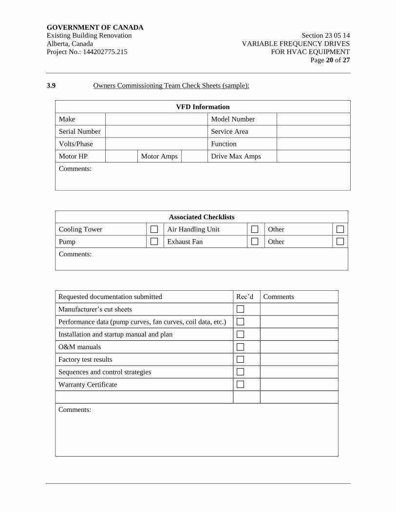
GOVERNMENT OF CANADA Existing Building Renovation Section 23 05 14
Alberta, Canada VARIABLE FREQUENCY DRIVES
Project No.: 144202775.215 FOR HVAC EQUIPMENT
Page 20 of 27
3.9 Owners Commissioning Team Check Sheets (sample):
Associated Checklists
Cooling Tower Air Handling Unit Other
Pump Exhaust Fan Other
Comments:
Requested documentation submitted Rec’d Comments
Manufacturer’s cut sheets
Performance data (pump curves, fan curves, coil data, etc.)
Installation and startup manual and plan
O&M manuals
Factory test results
Sequences and control strategies
Warranty Certificate
Comments:
VFD Information
Make Model Number
Serial Number Service Area
Volts/Phase Function
Motor HP Motor Amps Drive Max Amps
Comments:

GOVERNMENT OF CANADA Existing Building Renovation Section 23 05 14
Alberta, Canada VARIABLE FREQUENCY DRIVES
Project No.: 144202775.215 FOR HVAC EQUIPMENT
Page 21 of 27
Installation Checks
Check if Acceptable; Provide comment if unacceptable A N
A
Comment
General
Installation per manufacturer's requirements
Permanent label affixed and UL stamp approved
Drive location not subject to excessive moisture or dirt
Drive location not subject to excessive temperatures
Appropriate Volts vs. Hz curve is being used
Drive independently mounted
Cooling air flow path clean and unobstructed
VFD interlocked to control system
Unit is programmed with full written programming record on
site
Accel time set to __________ and Decel time set to
__________
Coordinated with BAS for all interface ranges and signal
isolation
Restart on Power Failure parameter set to auto
Drive min and max speed set to ______ Hz min and 60 Hz
max
Security settings set per owner direction and Password
documented for owner
Drive response to loss of signal set to __________
Output pulse resolution set to _________ MHz. (This is
coordinated with the application to minimize audible noise
and coordinated with driven bearing allowances.)
Input of motor FLA represents 100% to 105% of motor FLA
rating
Upper frequency limit set at 100%, unless explained
otherwise
Electrical and Controls
Power disconnect is located within site of the unit it controls
and labeled

GOVERNMENT OF CANADA Existing Building Renovation Section 23 05 14
Alberta, Canada VARIABLE FREQUENCY DRIVES
Project No.: 144202775.215 FOR HVAC EQUIPMENT
Page 22 of 27
Installation Checks
Check if Acceptable; Provide comment if unacceptable A N
A
Comment
All electric connections tight
Grounding installed for components and unit
Safeties installed and operational
Overload breakers installed and correct size
All control devices and wiring complete
Control system interlocks connected and functional
Installation per manufacturer’s instructions
Rotates in the correct direction (for VFD, check Inverter and
BYPASS modes)
Checked the input voltage with drive disconnected
Operational Checks
Check if Acceptable; Provide comment if unacceptable N
A
Comment
Operation checked in HAND, OFF, and AUTO. As applicable
operation also checked in BYPASS. Where applicable, ensure
safeties are active in all modes
Specified point-to-point checks have been completed and
documentation record submitted for this system
Start-up complete

GOVERNMENT OF CANADA Existing Building Renovation Section 23 05 14
Alberta, Canada VARIABLE FREQUENCY DRIVES
Project No.: 144202775.215 FOR HVAC EQUIPMENT
Page 23 of 27
3.10 Vendors sample start-up sheet
VFD Tag:
Pkg. S/N:
Date:
Commissioning
Agent
Phone
Service
Technician
Fax
Customer: Phone:
Address: Fax:
Email:
Project: Building:
Address:
Site Contact: Phone:
Name: Fax:
Email:
NAMEPLATE INFORMATION
Package Type: VFD
Tag:
Location:
Package
Model:
S/N: Application:
VFD Model: HP (CT) HP (VT) Voltage:
S/N: FLA
(CT)
FLA (VT) Logic #
MFG Date

GOVERNMENT OF CANADA Existing Building Renovation Section 23 05 14
Alberta, Canada VARIABLE FREQUENCY DRIVES
Project No.: 144202775.215 FOR HVAC EQUIPMENT
Page 24 of 27
# Code
Motor Make: Voltage: HP:
Model: RPM: FLA:
Insulation
Class:
Frame SF: Type:
Ambient
Temp:
Duty
Cycle:
Efficiency: Frequency:
PRE POWER-UP CHECKS
Line
Reactor
Make: Model: Connectio
n:
Load
Reactor
Make: Model: Connectio
n:
Filters Outpu
t:
RFI: Arrestor:
Environment Temp. with -10 to 40C (14 to
104F)
If
No:
Humidity OK? If
No:
Adequate Ventilation? If
No:
Drip Shield? If
No:
Clean? If
No:
Wirin
g:
Input
Power
Complete
?
Separate
Conduit?
Proper Size?
Output
Power
Separate
Conduit?
Proper Size?
AC Control Separate
Conduit?
Proper Size?
DC Control Separate Proper Size?

GOVERNMENT OF CANADA Existing Building Renovation Section 23 05 14
Alberta, Canada VARIABLE FREQUENCY DRIVES
Project No.: 144202775.215 FOR HVAC EQUIPMENT
Page 25 of 27
Conduit?
Grounding Proper Size?
Fuses Input
Power:
Control XFMR
Primary
Control XFMR
Secondary:
Motor Megger
Test
POWERED CHECKS
Power Supply Vab: V Vac: V Vbc: V
+/- 10%
?
V a-b-c Balanced with 3% ?
DC Bus: Within 5% of input? (AC x
1.414)
Motor
Rotation
VFD: Bypass Free Run Stop
Time
sec
Motor
Current
(in amps)
VFD @ 60
Hz:
A @ 45
Hz
A
@ 30
Hz:
A @ 15
Hz:
A
Current within specification at all frequency
ranges?
Bypass A Current within specification?
Signal Input Type OK? Output Type OK?
Frequency
Reference:
Frequency
Feedback:
Run: Current Feedback:
External Interlocks: Run Status:
Run Permissive: Fault Status:
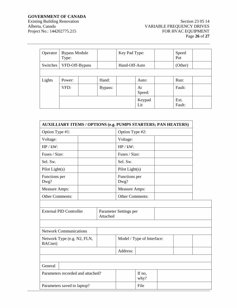
GOVERNMENT OF CANADA Existing Building Renovation Section 23 05 14
Alberta, Canada VARIABLE FREQUENCY DRIVES
Project No.: 144202775.215 FOR HVAC EQUIPMENT
Page 26 of 27
Operator Bypass Module
Type:
Key Pad Type: Speed
Pot
Switches VFD-Off-Bypass Hand-Off-Auto (Other)
Lights Power: Hand: Auto: Run:
VFD: Bypass: At
Speed:
Fault:
Keypad
Lit
Ext.
Fault:
AUXILLIARY ITEMS / OPTIONS (e.g. PUMPS STARTERS; PAN HEATERS)
Option Type #1: Option Type #2:
Voltage: Voltage:
HP / kW: HP / kW:
Fuses / Size: Fuses / Size:
Sel. Sw. Sel. Sw.
Pilot Light(s) Pilot Light(s)
Functions per
Dwg?
Functions per
Dwg?
Measure Amps: Measure Amps:
Other Comments: Other Comments:
External PID Controller Parameter Settings per
Attached
Network Communications
Network Type (e.g. N2, FLN,
BACnet)
Model / Type of Interface:
Address:
General
Parameters recorded and attached? If no,
why?
Parameters saved to laptop? File

GOVERNMENT OF CANADA Existing Building Renovation Section 23 05 14
Alberta, Canada VARIABLE FREQUENCY DRIVES
Project No.: 144202775.215 FOR HVAC EQUIPMENT
Page 27 of 27
Name:
Parameters uploaded to keypad?
Manual in the package? If no,
why?
Wiring diagram in the package? If no,
why?
“As Commissioned” marked up dwgs
attached?
If no,
why?
Other instruction manuals in the package? If no,
why?
Any changes to the package? If yes, then notify us with the
changes
Commissioning Completed by (print):
Sign:
Commissioning Completion Date:
END OF SECTION
GOVERNMENT OF CANADA Existing Building Renovation Section 23 05 19
Alberta, Canada METERS AND GAUGES FOR HVAC SYSTEMS
Project No.: 144202775.215 Page 1 of 5
1. General
1.1 Scope
.1 Provide meters, gauges and taps where shown on drawings and/or specified herein.
1.2 Reference Documents
.1 American Society of Mechanical Engineers (ASME):
.1 ASME Fluid Meter’s Handbook: Their Theory and Application, Sixth
Edition [1971].
.2 ASME B40.100 Pressure Gauges and Gauge
Attachments.
.3 ASME B40.200 Thermometers, Direct Reading and
Remote Reading.
.2 Canadian General Standards Board (CGSB).
.1 CAN/CGSB-14.4 Thermometers, Liquid-in-Glass, Self
Indicating, Commercial/Industrial Type.
.2 CAN/CGSB-14.5 Thermometers, Bimetallic,
Self-Indicating, Commercial/Industrial
Type.
.3 Health Canada/Workplace Hazardous Materials Information System (WHMIS):
.4 Material Safety Data Sheets (MSDS).
1.3 Delivery & Storage
.1 Deliver and store materials in accordance with Section 23 05 00 – Common Work
Results for HVAC.
1.4 Waste Management and Disposal
.1 Separate waste materials for reuse and recycling in accordance with Section 23 05 00 –
Common Work Results for HVAC.
1.5 Submittals
.1 Submit shop drawings of proposed products to the engineer for review.
.2 Submit list of all meters, including location, service, flow and corresponding reading for
flow.
GOVERNMENT OF CANADA Existing Building Renovation Section 23 05 19
Alberta, Canada METERS AND GAUGES FOR HVAC SYSTEMS
Project No.: 144202775.215 Page 2 of 5
.3 Submit shop drawings on thermometers, pressure gauges and meters. Shop drawings are
to indicate, as minimum, the following:
.1 Service conditions.
.2 Full details of primary element including standard of design and construction,
materials.
.3 Accuracy statements for each component at specified flow rates and other
conditions.
.4 Flow, temperature or pressure ranges.
.5 Signal processor calibration data.
2. Products
2.1 Acceptable Manufacturers
1. Thermometers: Ashcroft, Marsh Bellofram, Trerice, Weiss, Weksler,
Wika, Winters
2. Pressure Gauges: Ashcroft, Marsh Bellofram, Trerice, Weiss, Weksler,
Wika, Winters
3. Static Pressure Gauges: Dwyer, Magnehelic
2.2 Thermometers
.1 Dial Thermometers: 75m (3”) diameter dial in drawn steel case, bimetallic helix actuated,
brass separable socket or flange and bushing, glass cover, adjustable pointer.
.2 Mercury Thermometer: Red reading mercury filled, 2° graduations, plastic or aluminum
case, 230mm (9”) scale, straight shank, separable socket, adjustable angle.
.3 Provide separable brass wells to suit pipe diameter and extensions for insulation. For
duct thermometers, provide extension stems, aluminum fastening flange and extension
for insulation.
.4 Thermometer range to suit service.
.5 Graduate thermometers with Fahrenheit and Celsius scales.
2.3 Pressure Gauges
.1 100mm (4”) diameter, drawn steel case, phosphor bronze bourdon tube, brass movement,
extruded brass socket, 1% midscale accuracy, front calibration adjustment, black figures
on white background. Pressure gauges shall be liquid filled with ½% accuracy in
locations subject to vibration (on pumps, air handling units, and chillers), and 1%
accuracy in all other locations. Provide needle valve and syphon for steam service,
pulsating damper and ball valve for water service.
GOVERNMENT OF CANADA Existing Building Renovation Section 23 05 19
Alberta, Canada METERS AND GAUGES FOR HVAC SYSTEMS
Project No.: 144202775.215 Page 3 of 5
.2 Provide each gauge with brass gauge cock or needle valve.
.3 Pressure range to suit service.
2.4 Pressure/Temperature Taps (Pete's Plugs)
.1 Fitting to allow a 3mm (12 gauge) O.D. plug-in gauge to measure temperature or
pressure.
.1 Maximum pressure: 3450 kPa (500 psi)
.2 Maximum temperature: 135°C (275°F)
.2 Fitting constructed of:
.1 6mm (¼”) NPT brass body with hex head screw cap and gasket.
.2 Protective screw cap to have retaining strap.
.3 Two self-closing valves constructed of nordel.
.3 Test kit including the following:
.1 One 65mm (2½”) diameter pressure gauge with 3mm (12 gauge) O.D. plug-in
stem.
.2 Two 45mm (1¾”) diameter temperature gauges with 3mm (12 gauge) O.D. x
125m (5”) plug-in stem, range 0°C to 110°C (32°F to 230°F).
.3 All above in protective carrying case with operating instructions.
.4 Installation:
.1 Install pressure/temperature taps into threaded pipe nipples welded to wall of
pipe. Locate fittings in accessible spaces.
.2 Provide one pressure/temperature taps test kit.
2.5 Static Pressure Gauges
.1 Dial Gauge: 100mm (4”) dial, diaphragm actuated, suitable for positive, negative, or
differential pressure measurement. Accuracy within ±2% of full scale, complete with
static pressure tips and mounting accessories.
.2 Inclined Vertical Manometer: molded plastic manometer, accuracy within ±3% of full
scale, suitable for positive, negative or differential pressure measurement, complete with
static pressure tips, and mounting accessories.
GOVERNMENT OF CANADA Existing Building Renovation Section 23 05 19
Alberta, Canada METERS AND GAUGES FOR HVAC SYSTEMS
Project No.: 144202775.215 Page 4 of 5
3. Execution
3.1 Thermometers – Installation
.1 Provide thermometers at the inlet and outlet side of all equipment and components which
create a temperature difference for both air and water circuits.
.2 Thermometer locations are generally indicated, however, additional units may be
required based on as-built conditions.
.3 Check all thermometers for accuracy and recalibrate where necessary before work is
handed over.
3.2 Pressure Gauges – Installation
.1 Provide pressure gauges at the inlet and outlet side of all components which create a
pressure difference.
.2 Pressure gauge locations are generally indicated, however, additional units may be
required based on as-built conditions.
.3 Check all pressure gauges for accuracy and recalibrate where necessary before work is
handed over.
3.3 Meters, Gauges and Flow Measuring Devices
.1 All mechanical equipment shall be provided with instrumentation or test ports to verify
critical parameters, such as capacity, pressures, temperatures and flow rates.
.2 For gauges on liquid service, provide tee in piping with bronze pulsation damper and ball
isolation valve.
.3 Select gauges so that normal operating point is approximately mid-point of instrument
range.
.4 Install gauges between equipment and first fitting valve.
.5 Install gauges in locations and angles that are easily readable from normal sight.
.6 Provide extensions where pressure gauges or thermometers are installed through
insulation.
.7 Install pressure/temperature taps into threaded pipe nipples welded to wall of pipe.
Locate fittings in accessible spaces.
.8 Install flow meters in uninterrupted straight pipe, minimum 5 pipe diameters downstream
and 10 pipe diameters upstream, or according to manufacturer’s recommendations.
Minimum 3 pipe diameters lateral from any physical obstruction to insertion of meter
probes.
GOVERNMENT OF CANADA Existing Building Renovation Section 23 05 19
Alberta, Canada METERS AND GAUGES FOR HVAC SYSTEMS
Project No.: 144202775.215 Page 5 of 5
.9 Flow measuring devices shall be capable of communication with the central building
automation system.
.10 Water flow devices shall conform to the requirements of ASHRAE Standard 90.1.
.11 On pipes 65mm (2½”) and smaller, place well in tee used in lieu of an elbow to
accommodate well.
3.4 Meters and Gauges Installation Schedule
.1 Pressure Gauges:
.1 Where shown on drawings
.2 Pressure/Temperature Taps - Pete's Plugs:
.1 Where shown on drawings
.3 Thermometers:
.1 Where shown on drawings
.4 Static Pressure Gauges:
.1 Across built-up filter banks
.2 Across unitary filter sections
.3 Across supply and return fans
.4 And where shown on drawings
.5 Static Pressure Taps:
.1 Across all major dampers
.2 Across filter banks
.3 And where shown on drawings
END OF SECTION
GOVERNMENT OF CANADA Existing Building Renovation Section 23 05 29
Alberta, Canada HANGERS AND SUPPORTS FOR
Project No.: 144202775.215 HVAC PIPING AND EQUIPMENT
Page 1 of 14
1. General
1.1 Scope
.1 Pipe hangers and supports
.2 Duct hangers and supports
.3 Sleeving for mechanical equipment
.4 Equipment bases and supports
.5 Pipe anchors
.6 Access Doors
1.2 Reference Standards
.1 American National Standards Institute/ American Society of Mechanical Engineers
(ANSI/ASME)
.1 ANSI/ASME B31.1 Power Piping, (SI Edition).
.2 American Society for Testing and Materials (ASTM)
.1 ASTM A125 Specification for Steel Springs, Helical,
Heat-Treated.
.2 ASTM A307 Specification for Carbon Steel Bolts and
Studs, 60,000 PSI Tensile Strength.
.3 ASTM A563 Specification for Carbon and Alloy Steel
Nuts.
.3 Factory Mutual (FM)
.4 Manufacturer's Standardization Society of the Valves and Fittings Industry (MSS)
.1 MSS SP58 Pipe Hangers and Supports - Materials,
Design and Manufacture.
.2 MSS SP69 Pipe Hangers and Supports - Selection
and Application.
.3 MSS SP89 Pipe Hangers and Supports - Fabrication
and Installation Practices.
.5 National Fire Protection Association (NFPA):
GOVERNMENT OF CANADA Existing Building Renovation Section 23 05 29
Alberta, Canada HANGERS AND SUPPORTS FOR
Project No.: 144202775.215 HVAC PIPING AND EQUIPMENT
Page 2 of 14
.1 NFPA 13-2010 Standard for the Installation of Sprinkler
Systems
.6 Sheet Metal and Air Conditioning Contractors' National Association (SMACNA)
.1 SMACNA HVAC Duct Construction Standards - Metal and Flexible
.7 Underwriter's Laboratories of Canada (ULC)
1.3 General Requirements
.1 Provide hangers and supports to secure equipment in place, prevent vibration, maintain
grade,
.2 Provide for expansion and contraction of systems.
.3 Construct pipe hanger and support to manufacturer's recommendations utilizing
manufacturer's regular production components, parts and assemblies.
.4 Install supports of strength and rigidity to suit loading without unduly stressing the
building. Locate adjacent to equipment to prevent undue stresses in piping and
equipment. Where support is from concrete construction, avoid weakening concrete or
penetrating waterproofing.
.5 Select hangers and supports for the service and in accordance with manufacturer's
recommended maximum loading. Hangers shall have a safety factor of 5 to 1.
.6 Fasten supports and hangers to building structure. Use inserts for suspending hangers
from reinforced concrete slabs and sides of reinforced concrete beams wherever practical.
When possible, set inserts in position in advance of concrete work. Drill concrete where
inserts must be placed after concrete is poured.
.7 Ensure that supports, guides, anchors do not transmit excessive quantities of heat to
building structure.
.8 Where structural bearings do not exist or where inserts are not in suitable locations for
proper installation of pipes, conduits and ducts, provide approved support made of steel
channels or angles from which to suspend hangers. Do not use existing piping, crane
rails, trolley beams, mono rails, etc, for support.
.9 No percussion type fastening of any kind will be permitted without prior approval.
.10 Provide and set sleeves or block-outs required for equipment, including openings
required for placing equipment.
.11 Provide sleeves for all piping through rated assemblies. In non-rated assemblies, provide
sleeves for all heating, cooling, steam, condensate, domestic hot, domestic cold, and
domestic recirculation piping. Sleeves to be sized to allow insulation to pass through to
both sides of wall.
GOVERNMENT OF CANADA Existing Building Renovation Section 23 05 29
Alberta, Canada HANGERS AND SUPPORTS FOR
Project No.: 144202775.215 HVAC PIPING AND EQUIPMENT
Page 3 of 14
.12 Provide sleeves for all piping through ceilings, floors and footings.
.13 Provide sleeves for duct penetrations through walls, ceilings, floors and footings.
Provide locations and dimensions for block-outs imbedded material if provided by others.
.14 Do not weld piping, ductwork or equipment supports to building metal decking or
building structural steel supports unless prior written approval has been obtained from the
structural engineer.
.15 Obtain approval prior to drilling for inserts and supports for piping system. Discuss and
obtain approval for hanging systems and methods with Structural Engineer.
.16 Obtain approval prior to using percussion type fastenings.
.17 Use of piping or equipment for hanger supports and use of perforated band iron, wire or
chain as hangers is not permitted.
1.4 Submittals
.1 Submit shop drawings and product data for the following items:
.1 Access doors
.2 Bases, hangers and supports
.3 Connections to equipment and structure
1.5 Delivery & Storage
.1 Deliver and store materials in accordance with Section 23 05 00 – Common Work
Results for HVAC.
1.6 Waste Management and Disposal
.1 Separate waste materials for reuse and recycling in accordance with Section 23 05 00 –
Common Work Results for HVAC.
2. Products
2.1 Acceptable Manufacturers
1. Pipe Hangers: Anvil, Cooper B-Line, Crane
2. Access Doors: Acudor, Maxam, Mifab, Milcor, Williams Brothers
2.2 Inserts
.1 Provide inserts to cast in concrete of malleable cast iron or galvanized steel and expander
plug for threaded connection with lateral adjustment, top slot for reinforcing rods, lugs
for attaching to forms.
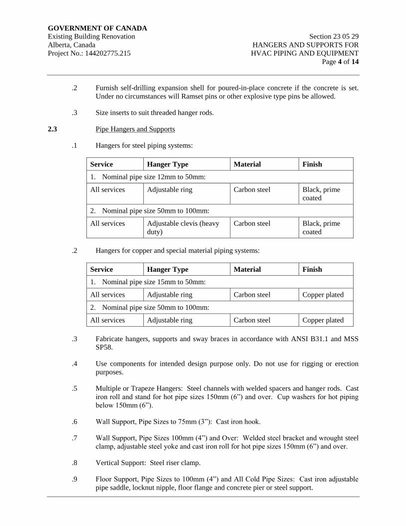
GOVERNMENT OF CANADA Existing Building Renovation Section 23 05 29
Alberta, Canada HANGERS AND SUPPORTS FOR
Project No.: 144202775.215 HVAC PIPING AND EQUIPMENT
Page 4 of 14
.2 Furnish self-drilling expansion shell for poured-in-place concrete if the concrete is set.
Under no circumstances will Ramset pins or other explosive type pins be allowed.
.3 Size inserts to suit threaded hanger rods.
2.3 Pipe Hangers and Supports
.1 Hangers for steel piping systems:
Service Hanger Type Material Finish
1. Nominal pipe size 12mm to 50mm:
All services Adjustable ring Carbon steel Black, prime
coated
2. Nominal pipe size 50mm to 100mm:
All services Adjustable clevis (heavy
duty)
Carbon steel Black, prime
coated
.2 Hangers for copper and special material piping systems:
Service Hanger Type Material Finish
1. Nominal pipe size 15mm to 50mm:
All services Adjustable ring Carbon steel Copper plated
2. Nominal pipe size 50mm to 100mm:
All services Adjustable ring Carbon steel Copper plated
.3 Fabricate hangers, supports and sway braces in accordance with ANSI B31.1 and MSS
SP58.
.4 Use components for intended design purpose only. Do not use for rigging or erection
purposes.
.5 Multiple or Trapeze Hangers: Steel channels with welded spacers and hanger rods. Cast
iron roll and stand for hot pipe sizes 150mm (6”) and over. Cup washers for hot piping
below 150mm (6”).
.6 Wall Support, Pipe Sizes to 75mm (3”): Cast iron hook.
.7 Wall Support, Pipe Sizes 100mm (4”) and Over: Welded steel bracket and wrought steel
clamp, adjustable steel yoke and cast iron roll for hot pipe sizes 150mm (6”) and over.
.8 Vertical Support: Steel riser clamp.
.9 Floor Support, Pipe Sizes to 100mm (4”) and All Cold Pipe Sizes: Cast iron adjustable
pipe saddle, locknut nipple, floor flange and concrete pier or steel support.
GOVERNMENT OF CANADA Existing Building Renovation Section 23 05 29
Alberta, Canada HANGERS AND SUPPORTS FOR
Project No.: 144202775.215 HVAC PIPING AND EQUIPMENT
Page 5 of 14
.10 Floor Support, Hot Pipe Sizes 125mm (5”) and Over: Adjustable cast iron roll and stand,
steel screws and concrete pier to steel support.
.11 Design hangers so they cannot become disengaged by movements of supported pipe.
.12 Provide copper plated hangers and supports for copper piping.
.13 Provide galvanized hangers and supports for galvanized piping.
2.4 Hanger Rods
.1 Provide galvanized rods, threaded both ends, threaded one end, or continuous threaded.
2.5 Riser Clamps
.1 Steel or cast iron pipe: galvanized carbon steel to MSS SP58, type 42.
.2 Copper pipe: carbon steel copper plated to MSS SP58, type 42.
.3 Bolts: to ASTM A307.
.4 Nuts: to ASTM A563.
2.6 Insulation Protection Shields
.1 Insulated cold piping:
.1 64 kg/m3 density insulation plus insulation protection shield to: MSS SP69,
galvanized sheet carbon steel. Length designed for maximum 3 m span.
.2 Insulated hot piping:
.1 Curved plate 300mm (12”) long, with edges turned up, welded-in centre plate for
pipe sizes 15mm (½”) and over, carbon steel to comply with MSS SP69.
2.7 Constant Support Spring Hangers
.1 Springs: alloy steel to ASTM A125, shot peened, magnetic particle inspected, with ±5%
spring rate tolerance, tested for free height, spring rate, loaded height and provided with
Certified Mill Test Report(CMTR).
.2 Load adjustability: 10% minimum adjustability each side of calibrated load. Adjustment
without special tools. Adjustments not to affect travel capabilities.
.3 Provide upper and lower factory set travel stops.
.4 Provide load adjustment scale for field adjustments.
.5 Total travel to be actual travel +20%. Difference between total travel and actual travel
25mm (1”) minimum.
GOVERNMENT OF CANADA Existing Building Renovation Section 23 05 29
Alberta, Canada HANGERS AND SUPPORTS FOR
Project No.: 144202775.215 HVAC PIPING AND EQUIPMENT
Page 6 of 14
.6 Individually calibrated scales on each side of support calibrated prior to shipment,
complete with calibration record.
2.8 Variable Support Spring Hangers
.1 Vertical movement: 15mm (½”) minimum, 50mm (2”) maximum, use single spring
pre-compressed variable spring hangers.
.2 Vertical movement greater than 50mm (2”): use double spring pre-compressed variable
spring hanger with 2 springs in series in single casing.
.3 Variable spring hanger to be complete with factory calibrated travel stops.
.4 Steel alloy springs: to ASTM A125, shot peened, magnetic particle inspected, with ±5 %
spring rate tolerance, tested for free height, spring rate, loaded height and provided with
CMTR.
2.9 Equipment Supports
.1 Fabricate equipment supports not provided by equipment manufacturer from structural
grade steel meeting requirements of Division 05 – Metals. Submit calculations with shop
drawings.
2.10 Equipment Anchor Bolts and Templates
.1 Provide templates to ensure accurate location of anchor bolts.
2.11 Duct Hangers and Supports
.1 Conform to SMACNA manuals.
2.12 Sleeves
.1 Place pipe sleeves at all points where pipes pass through masonry or concrete walls or
floors.
.2 Size sleeves in order to provide approximately 6.5mm (¼”) clearance, all around,
between the sleeve and the duct or pipes, or where the pipe is insulated, provide
approximately 6.5mm (¼”) clearance all around between the sleeve and insulation. Size
sleeves through footings large enough to accommodate hub of cast iron soil pipe. Sleeve
piping and drains where they pass below any footing to provide a minimum all around
clearance of 50mm (2”) and backfill up the underside of the footing with concrete of the
same strength as the footing.
.3 Terminate sleeves flush with walls and ceilings, 50mm above floors generally and
100mm above finished floor level in mechanical rooms.
GOVERNMENT OF CANADA Existing Building Renovation Section 23 05 29
Alberta, Canada HANGERS AND SUPPORTS FOR
Project No.: 144202775.215 HVAC PIPING AND EQUIPMENT
Page 7 of 14
.4 Where sleeves are required for pipes passing through the roof, anchor the sleeve in roof
construction, caulk between sleeve recess and stack, fasten roof flashing to the clamp
device, make a water-tight durable joint.
.5 Fill all voids between sleeve material and pipe, conduit or duct passing through. Use the
following procedure for sleeve caulking:
.1 Where sleeves pass through walls or floors, caulk the space between the pipe and
sleeve with dry oakum and seal each side with a non-hardening mastic.
.2 Ensure no contact between copper tube or pipe and ferrous sleeve.
.6 Where piping or ducts pass through a construction which is required to have a specific
fire resistance rating, seal any space between the pipe or duct and the construction,
including the space between the pipe or duct and the sleeve, with non-combustible
insulating material and close off on both sides with tight fitting metal caps constructed of
1.6mm metal. Use caulking approved by the consultant and by all authorities having
jurisdiction.
.7 Pipes through Floors: Form with steel pipe or approved PVC sleeves.
.8 Pipes through Beams, Walls, Fire Proofing, Footings, Potentially Wet Floor: Form with
steel pipe.
.9 Ducts: Form with galvanized steel.
.10 Size sleeve large enough to allow for movement due to expansion and to provide for
continuous insulation.
2.13 Access Doors
.1 Types:
.1 Drywall Surface – Flanged Door: Universal flush access door with concealed bar
hinge and rounded safety corners; Acudor UF-5000.
.2 Drywall Surface – Hidden Flange: Access door with concealed bar hinge and
rounded safety corners; flange of textured galvanized steel drywall taping bead
with pre-punched holes; installed after drywall; Acudor DW-5040.
.3 Masonry: Universal flush access door with concealed bar hinge and rounded
safety corners; Acudor UF-5000.
.4 Tile Surface: Stainless steel, universal flush access door with concealed bar
hinge and rounded safety corners; Acudor UF-5000.
.5 Plaster Walls and Ceilings: Access door with expansion casing bead and 75mm
(3”) wide galvanized lath surround recessed 19mm (¾”) to receive plaster;
Acudor PS-5030.
GOVERNMENT OF CANADA Existing Building Renovation Section 23 05 29
Alberta, Canada HANGERS AND SUPPORTS FOR
Project No.: 144202775.215 HVAC PIPING AND EQUIPMENT
Page 8 of 14
.6 Acoustic Plaster: 15mm (⅝”) 5ecessed access door with self-furring lath and
75mm (3”) galvanized lath surround recessed 19mm (¾”) to receive plaster;
Acudor AP-5010.
.7 Acoustical Tile Ceilings: Door recessed 25mm (1”) to receive acoustic tile;
Acudor AT-5020.
.8 Fire Rated Walls: Self-closing, self-latching door; ULC – 2 hour “B” label; For
use when temperature rise is not a factor; Acudor FB-5060.
.9 Fire Rated Walls: Self-closing, self-latching door with 50mm (2”) fire rated
insulation; ULC – 2 hour “B” label with a maximum temperature rise of 139°C
(250°F) after 30 minutes; For use when temperature rise or heat transmission is a
factor; Acudor FW-5050.
.10 Fire Rated Ceilings: Self-closing, self-latching, inward opening door with 50mm
(2”) fire rated insulation; ULC – 2 hour “B” label with a maximum temperature
rise of 139°C (250°F) after 30 minutes; For use when temperature rise or heat
transmission is a factor; Acudor FW-5050-UP.
.2 Construction
.1 Non-Rated Doors: One piece outer flange welded to mounting frame;
Continuous, concealed hinge; Doors 400mm x 400mm (16”x16”) and smaller –
16 gauge door, 18 gauge mounting frame; Doors over 400mm x 400m (16”x16”)
– 14 gauge door, 16 gauge mounting frame.
.2 Rated Doors: 25mm (1”) wide flange; Continuous, concealed hinge; 20 gauge
door, 16 gauge mounting frame.
.3 Stainless steel screwdriver operate cam latch (non-rated doors); Universal self-
latching bolt operated by a knurled knob or flush key (rated doors).
.4 Steel access doors: 5 stage iron phosphate preparation with prime coat of grey
baked enamel.
.5 Stainless steel doors: #4 satin polish.
3. Execution
3.1 General
.1 Install as per manufacturer’s instructions and recommendations.
.2 Provide rigid anchors for ducts and pipes immediately after vibration isolation
connections to equipment unless spring hangers are specified.
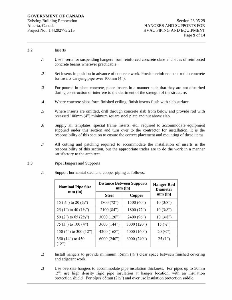
GOVERNMENT OF CANADA Existing Building Renovation Section 23 05 29
Alberta, Canada HANGERS AND SUPPORTS FOR
Project No.: 144202775.215 HVAC PIPING AND EQUIPMENT
Page 9 of 14
3.2 Inserts
.1 Use inserts for suspending hangers from reinforced concrete slabs and sides of reinforced
concrete beams wherever practicable.
.2 Set inserts in position in advance of concrete work. Provide reinforcement rod in concrete
for inserts carrying pipe over 100mm (4”).
.3 For poured-in-place concrete, place inserts in a manner such that they are not disturbed
during construction or interfere to the detriment of the strength of the structure.
.4 Where concrete slabs form finished ceiling, finish inserts flush with slab surface.
.5 Where inserts are omitted, drill through concrete slab from below and provide rod with
recessed 100mm (4”) minimum square steel plate and nut above slab.
.6 Supply all templates, special frame inserts, etc., required to accommodate equipment
supplied under this section and turn over to the contractor for installation. It is the
responsibility of this section to ensure the correct placement and mounting of these items.
.7 All cutting and patching required to accommodate the installation of inserts is the
responsibility of this section, but the appropriate trades are to do the work in a manner
satisfactory to the architect.
3.3 Pipe Hangers and Supports
.1 Support horizontal steel and copper piping as follows:
Nominal Pipe Size
mm (in)
Distance Between Supports
mm (in) Hanger Rod
Diameter
mm (in) Steel Copper
15 (½”) to 20 (¾”) 1800 (72”) 1500 (60”) 10 (3/8”)
25 (1”) to 40 (1½”) 2100 (84”) 1800 (72”) 10 (3/8”)
50 (2”) to 65 (2½”) 3000 (120”) 2400 (96”) 10 (3/8”)
75 (3”) to 100 (4”) 3600 (144”) 3000 (120”) 15 (½”)
150 (6”) to 300 (12”) 4200 (168”) 4000 (160”) 20 (¾”)
350 (14”) to 450
(18”)
6000 (240”) 6000 (240”) 25 (1”)
.2 Install hangers to provide minimum 15mm (½”) clear space between finished covering
and adjacent work.
.3 Use oversize hangers to accommodate pipe insulation thickness. For pipes up to 50mm
(2”) use high density rigid pipe insulation at hanger location, with an insulation
protection shield. For pipes 65mm (2½”) and over use insulation protection saddle.
GOVERNMENT OF CANADA Existing Building Renovation Section 23 05 29
Alberta, Canada HANGERS AND SUPPORTS FOR
Project No.: 144202775.215 HVAC PIPING AND EQUIPMENT
Page 10 of 14
.4 Place a hanger within 300mm (12”) of each horizontal elbow.
.5 Use hangers which are vertically adjustable 40mm (1½”) minimum after piping is
erected.
.6 On insulated copper piping, affix lead or other approved backing to ensure no contact
between copper and ferrous hanger or other work.
.7 Support vertical piping not subject to expansion or contraction with bolted steel riser
clamps at each floor level or a maximum of 3000mm (10’-0”), whichever is shorter.
Secure vertical cast iron soil pipe with drive hooks at 1500mm (60”) intervals set below
hubs, and by riser clamps at each floor level.
.8 Vertical piping subject to expansion or contraction where grooved joint couplers are used
shall be supported with riser clamps at each floor level. Ensure at least one grooved joint
occurs between each floor.
.9 Vertical piping subject to expansion or contraction where welded or threaded shall be
supported and anchored at maximum 20mm intervals with expansion joints. Provide
guides at each floor.
.10 Provide supports for chromium plated piping or tubing or either chromium plated cast
brass or chromium plated die-cast zinc alloy. Where exposed, use chromium plated bolts,
screws, and nuts for assembly and attachment of such supports. Use supports for pipes
running along walls of such length that the clearance between the pipe and the face of the
wall will not be less than 20mm and not more than 25mm.
.11 Place piping hung or supported by rising or clevis hangers directly onto the hanger and
insulation carried over the hanger, finish insulation neatly where the hanger protrudes
over the insulation. Provide piping 50mm and over with pipe covering protection saddles
and insulation butted against the saddle, also provide insulation between the pipe and
saddle.
.12 Where piping is supported from floor, use cast iron adjustable pipe saddle supports with
locknut nipple, floor flange and concrete pier or steel support. Where provision for
expansion or contraction is required, use adjustable pipe roll stands with vertical
adjustment and concrete pier or steel support.
.13 Support cast iron horizontal drainage pipe near each hub and on each side of gasket and
clamp joints, with 1500mm (60”) maximum spacing between hangers.
.14 For all horizontal drainage pipe (sanitary and storm) below structural slabs, provide
clevis ring hangers supported from the structural slab.
.15 Provide insulation saddles for insulated pipe.
.16 For steel cold water insulated pipe, use prefabricated insulated shields with high density
insulation and vapor barrier. Shield length to be four times insulation outside diameter.
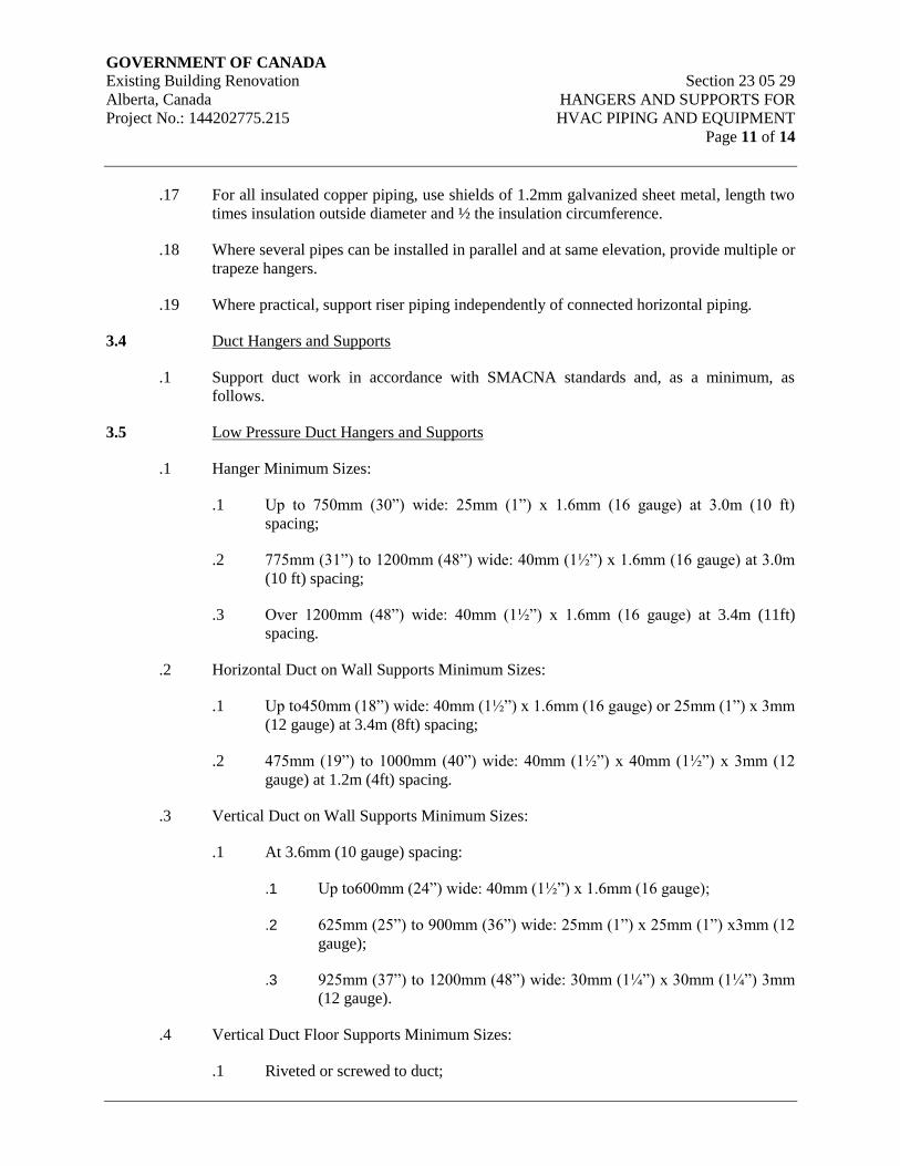
GOVERNMENT OF CANADA Existing Building Renovation Section 23 05 29
Alberta, Canada HANGERS AND SUPPORTS FOR
Project No.: 144202775.215 HVAC PIPING AND EQUIPMENT
Page 11 of 14
.17 For all insulated copper piping, use shields of 1.2mm galvanized sheet metal, length two
times insulation outside diameter and ½ the insulation circumference.
.18 Where several pipes can be installed in parallel and at same elevation, provide multiple or
trapeze hangers.
.19 Where practical, support riser piping independently of connected horizontal piping.
3.4 Duct Hangers and Supports
.1 Support duct work in accordance with SMACNA standards and, as a minimum, as
follows.
3.5 Low Pressure Duct Hangers and Supports
.1 Hanger Minimum Sizes:
.1 Up to 750mm (30”) wide: 25mm (1”) x 1.6mm (16 gauge) at 3.0m (10 ft)
spacing;
.2 775mm (31”) to 1200mm (48”) wide: 40mm (1½”) x 1.6mm (16 gauge) at 3.0m
(10 ft) spacing;
.3 Over 1200mm (48”) wide: 40mm (1½”) x 1.6mm (16 gauge) at 3.4m (11ft)
spacing.
.2 Horizontal Duct on Wall Supports Minimum Sizes:
.1 Up to450mm (18”) wide: 40mm (1½”) x 1.6mm (16 gauge) or 25mm (1”) x 3mm
(12 gauge) at 3.4m (8ft) spacing;
.2 475mm (19”) to 1000mm (40”) wide: 40mm (1½”) x 40mm (1½”) x 3mm (12
gauge) at 1.2m (4ft) spacing.
.3 Vertical Duct on Wall Supports Minimum Sizes:
.1 At 3.6mm (10 gauge) spacing:
.1 Up to600mm (24”) wide: 40mm (1½”) x 1.6mm (16 gauge);
.2 625mm (25”) to 900mm (36”) wide: 25mm (1”) x 25mm (1”) x3mm (12
gauge);
.3 925mm (37”) to 1200mm (48”) wide: 30mm (1¼”) x 30mm (1¼”) 3mm
(12 gauge).
.4 Vertical Duct Floor Supports Minimum Sizes:
.1 Riveted or screwed to duct;
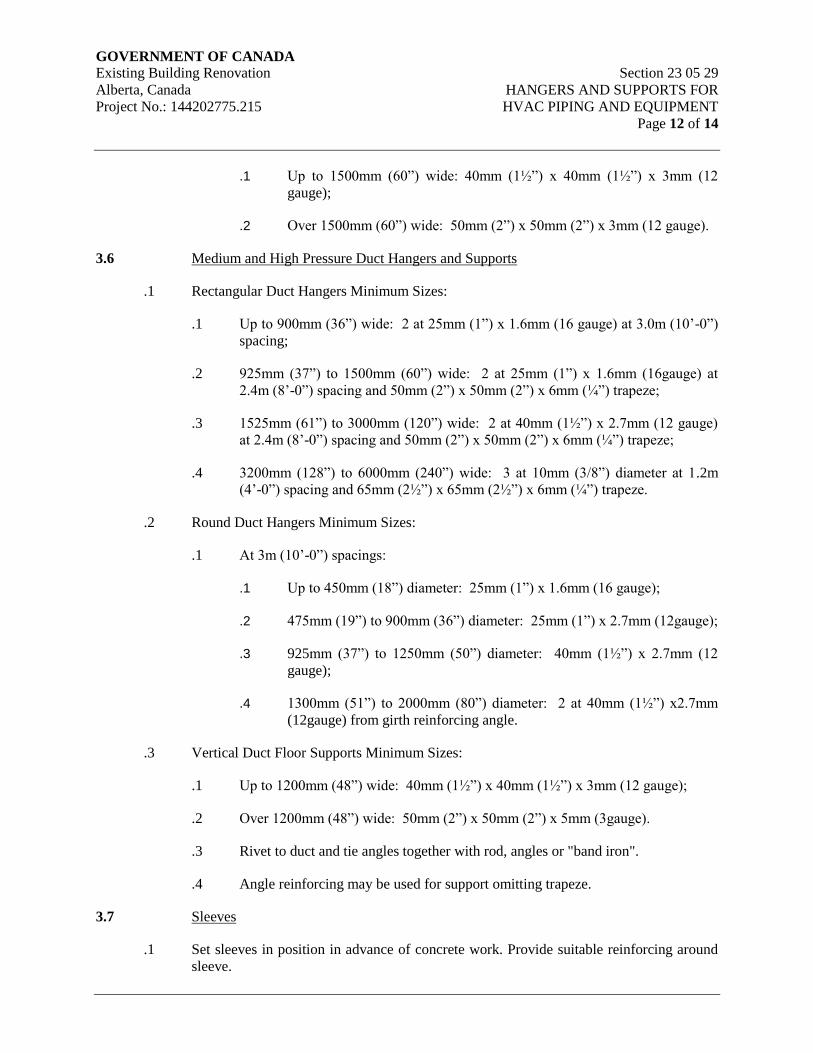
GOVERNMENT OF CANADA Existing Building Renovation Section 23 05 29
Alberta, Canada HANGERS AND SUPPORTS FOR
Project No.: 144202775.215 HVAC PIPING AND EQUIPMENT
Page 12 of 14
.1 Up to 1500mm (60”) wide: 40mm (1½”) x 40mm (1½”) x 3mm (12
gauge);
.2 Over 1500mm (60”) wide: 50mm (2”) x 50mm (2”) x 3mm (12 gauge).
3.6 Medium and High Pressure Duct Hangers and Supports
.1 Rectangular Duct Hangers Minimum Sizes:
.1 Up to 900mm (36”) wide: 2 at 25mm (1”) x 1.6mm (16 gauge) at 3.0m (10’-0”)
spacing;
.2 925mm (37”) to 1500mm (60”) wide: 2 at 25mm (1”) x 1.6mm (16gauge) at
2.4m (8’-0”) spacing and 50mm (2”) x 50mm (2”) x 6mm (¼”) trapeze;
.3 1525mm (61”) to 3000mm (120”) wide: 2 at 40mm (1½”) x 2.7mm (12 gauge)
at 2.4m (8’-0”) spacing and 50mm (2”) x 50mm (2”) x 6mm (¼”) trapeze;
.4 3200mm (128”) to 6000mm (240”) wide: 3 at 10mm (3/8”) diameter at 1.2m
(4’-0”) spacing and 65mm (2½”) x 65mm (2½”) x 6mm (¼”) trapeze.
.2 Round Duct Hangers Minimum Sizes:
.1 At 3m (10’-0”) spacings:
.1 Up to 450mm (18”) diameter: 25mm (1”) x 1.6mm (16 gauge);
.2 475mm (19”) to 900mm (36”) diameter: 25mm (1”) x 2.7mm (12gauge);
.3 925mm (37”) to 1250mm (50”) diameter: 40mm (1½”) x 2.7mm (12
gauge);
.4 1300mm (51”) to 2000mm (80”) diameter: 2 at 40mm (1½”) x2.7mm
(12gauge) from girth reinforcing angle.
.3 Vertical Duct Floor Supports Minimum Sizes:
.1 Up to 1200mm (48”) wide: 40mm (1½”) x 40mm (1½”) x 3mm (12 gauge);
.2 Over 1200mm (48”) wide: 50mm (2”) x 50mm (2”) x 5mm (3gauge).
.3 Rivet to duct and tie angles together with rod, angles or "band iron".
.4 Angle reinforcing may be used for support omitting trapeze.
3.7 Sleeves
.1 Set sleeves in position in advance of concrete work. Provide suitable reinforcing around
sleeve.
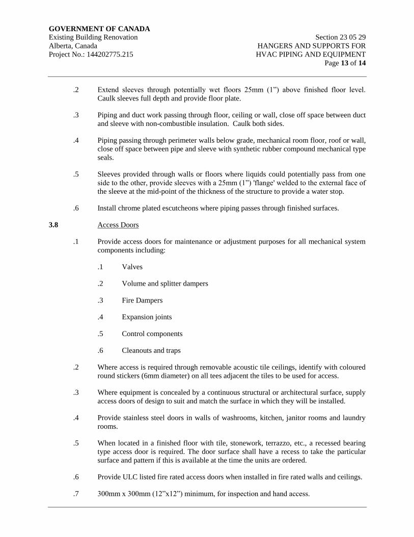
GOVERNMENT OF CANADA Existing Building Renovation Section 23 05 29
Alberta, Canada HANGERS AND SUPPORTS FOR
Project No.: 144202775.215 HVAC PIPING AND EQUIPMENT
Page 13 of 14
.2 Extend sleeves through potentially wet floors 25mm (1”) above finished floor level.
Caulk sleeves full depth and provide floor plate.
.3 Piping and duct work passing through floor, ceiling or wall, close off space between duct
and sleeve with non-combustible insulation. Caulk both sides.
.4 Piping passing through perimeter walls below grade, mechanical room floor, roof or wall,
close off space between pipe and sleeve with synthetic rubber compound mechanical type
seals.
.5 Sleeves provided through walls or floors where liquids could potentially pass from one
side to the other, provide sleeves with a 25mm (1”) 'flange' welded to the external face of
the sleeve at the mid-point of the thickness of the structure to provide a water stop.
.6 Install chrome plated escutcheons where piping passes through finished surfaces.
3.8 Access Doors
.1 Provide access doors for maintenance or adjustment purposes for all mechanical system
components including:
.1 Valves
.2 Volume and splitter dampers
.3 Fire Dampers
.4 Expansion joints
.5 Control components
.6 Cleanouts and traps
.2 Where access is required through removable acoustic tile ceilings, identify with coloured
round stickers (6mm diameter) on all tees adjacent the tiles to be used for access.
.3 Where equipment is concealed by a continuous structural or architectural surface, supply
access doors of design to suit and match the surface in which they will be installed.
.4 Provide stainless steel doors in walls of washrooms, kitchen, janitor rooms and laundry
rooms.
.5 When located in a finished floor with tile, stonework, terrazzo, etc., a recessed bearing
type access door is required. The door surface shall have a recess to take the particular
surface and pattern if this is available at the time the units are ordered.
.6 Provide ULC listed fire rated access doors when installed in fire rated walls and ceilings.
.7 300mm x 300mm (12”x12”) minimum, for inspection and hand access.
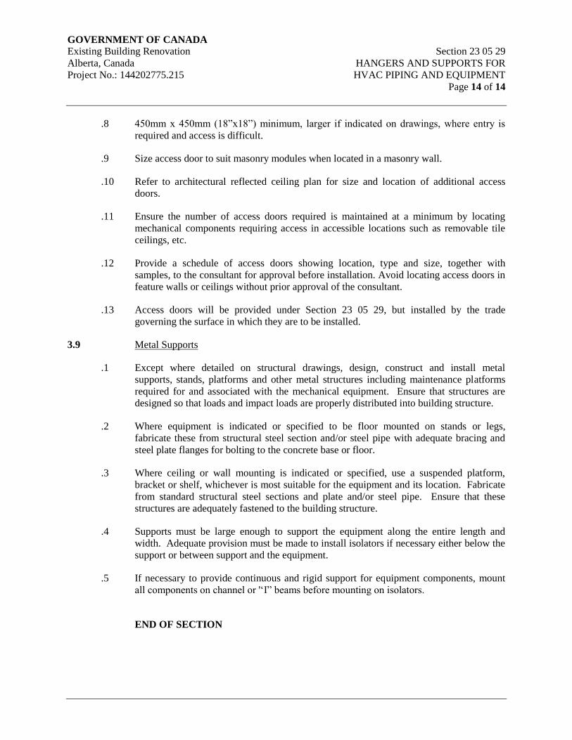
GOVERNMENT OF CANADA Existing Building Renovation Section 23 05 29
Alberta, Canada HANGERS AND SUPPORTS FOR
Project No.: 144202775.215 HVAC PIPING AND EQUIPMENT
Page 14 of 14
.8 450mm x 450mm (18”x18”) minimum, larger if indicated on drawings, where entry is
required and access is difficult.
.9 Size access door to suit masonry modules when located in a masonry wall.
.10 Refer to architectural reflected ceiling plan for size and location of additional access
doors.
.11 Ensure the number of access doors required is maintained at a minimum by locating
mechanical components requiring access in accessible locations such as removable tile
ceilings, etc.
.12 Provide a schedule of access doors showing location, type and size, together with
samples, to the consultant for approval before installation. Avoid locating access doors in
feature walls or ceilings without prior approval of the consultant.
.13 Access doors will be provided under Section 23 05 29, but installed by the trade
governing the surface in which they are to be installed.
3.9 Metal Supports
.1 Except where detailed on structural drawings, design, construct and install metal
supports, stands, platforms and other metal structures including maintenance platforms
required for and associated with the mechanical equipment. Ensure that structures are
designed so that loads and impact loads are properly distributed into building structure.
.2 Where equipment is indicated or specified to be floor mounted on stands or legs,
fabricate these from structural steel section and/or steel pipe with adequate bracing and
steel plate flanges for bolting to the concrete base or floor.
.3 Where ceiling or wall mounting is indicated or specified, use a suspended platform,
bracket or shelf, whichever is most suitable for the equipment and its location. Fabricate
from standard structural steel sections and plate and/or steel pipe. Ensure that these
structures are adequately fastened to the building structure.
.4 Supports must be large enough to support the equipment along the entire length and
width. Adequate provision must be made to install isolators if necessary either below the
support or between support and the equipment.
.5 If necessary to provide continuous and rigid support for equipment components, mount
all components on channel or '‘I” beams before mounting on isolators.
END OF SECTION
GOVERNMENT OF CANADA
Existing Building Renovation Section 23 05 48
Alberta, Canada VIBRATION AND SEISMIC
Project No.: 144202775.215 CONTROLS FOR HVAC
Page 1 of 15
1. General
1.1 Scope
.1 Vibration isolation for piping, ductwork and equipment
.2 Equipment isolation bases
.3 Flexible piping connections
.4 Resilient pipe anchors and guides
1.2 General
.1 Supply all labor, materials, and equipment required and necessary to isolate and restrain
the equipment as indicated on the drawings and specified herein and guarantee the
function of the materials and equipment supplied.
.2 Obtain all relevant equipment information and provide shop and placement drawings for
all vibration isolation elements for review, before materials are ordered. The drawings
shall bear the stamp and signature of the responsible supplier's technical representative.
.3 Provide attachment to both the equipment and the structure meeting the specified forces
involved.
1.3 Reference Standards
.1 National Building Code of Canada (NBC) 2010
.2 Alberta Building Code of Canada (ABC) 2014
1.4 Quality Assurance
.1 Provide and install appropriate vibration isolation materials/products on mechanical
equipment so that Average Noise Criteria curves, as outlined in ASHRAE Guide, are not
exceeded.
.2 All elastomeric components in type 1, type 2 isolation mounts shall be bridge bearing
neoprene, meeting CSA Standard CAN3-S6 Section 11.10.
.3 All vibration isolators and bases shall be supplied by an approved supplier with the
exception of isolators which are factory installed and are standard equipment with the
machinery.
.4 The work shall be carried out in accordance with the specification and, where applicable,
in accordance with the manufacturer's instructions and only by workmen experienced in
this type of work.
GOVERNMENT OF CANADA
Existing Building Renovation Section 23 05 48
Alberta, Canada VIBRATION AND SEISMIC
Project No.: 144202775.215 CONTROLS FOR HVAC
Page 2 of 15
.5 Equipment supplier to ensure equipment is sufficiently rigid for isolator point loading.
Project Mechanical Consultant must be advised of any equipment which requires an
additional support base, at least 7 working days prior to tender closing.
1.5 Delivery & Storage
.1 Deliver and store materials in accordance with Section 23 05 00 – Common Work
Results for HVAC.
1.6 Waste Management and Disposal
.1 Separate waste materials for reuse and recycling in accordance with Section 23 05 00 –
Common Work Results for HVAC.
1.7 Submittals
.1 The manufacturer of vibration isolation shall provide submittals for products as follows:
.1 Descriptive Data:
.1 Schedule of flexibly mounted equipment, referencing drawings by
number.
.2 Catalog cut or data sheets on vibration isolators.
.2 Drawings:
.1 Submit details of equipment bases including dimensions, structural
member sizes and support point locations.
.2 Submit details of isolation hangers for ceiling hung equipment, piping
and ductwork.
.3 Submit details of mountings for floor supported equipment, piping and
ductwork.
.4 All hanger, mounting or pad drawings shall indicate deflections and
model numbers as well as any other requirements in the specifications.
.5 Spring diameters, rated loads and deflections, heights at rated load and
closed height shall be provided for all springs shown in the submittals in
tabular form.
.6 Complete flexible connecter details.
.2 Provide an equipment isolation schedule that provides design data for each isolator
including: spring O.D., free operating and solid heights, minimum static deflection, and
ratio of horizontal to vertical stiffness.
GOVERNMENT OF CANADA
Existing Building Renovation Section 23 05 48
Alberta, Canada VIBRATION AND SEISMIC
Project No.: 144202775.215 CONTROLS FOR HVAC
Page 3 of 15
.3 Co-ordinate with Division 3 for the provision of housekeeping pads at least 100mm (4”)
high under all isolated equipment and where indicated on drawings. Provide at least
175mm (7”) clearance between drilled inserts and edge of housekeeping pads and follow
structural consultant's instructions for drilled inserts.
.4 Bolt all equipment to the structure. Do not bridge isolation elements.
2. Products
2.1 Acceptable Manufacturers
1. Vibration Controls: : Kinetics, IAC Acoustics, Korfund, Mason,
Vibro-Acoustic
2. Flexible Pipe Connectors : Flexonics, Mason
2.2 Description
.1 Provide vibration isolation on all motor driven equipment with motors of 0.37 kW (0.5
HP) and greater power output (as indicated on the motor nameplate) and on piping and
ductwork, as specified herein. For equipment less than 0.37 kW (0.5 HP), provide
neoprene grommets at the support points.
.2 Electrical cable connected to isolated equipment shall allow for a minimum ±25mm (±1”)
of equipment movement in any direction.
.3 Ensure isolation systems have a vertical natural frequency no higher than one third of the
lowest forcing frequency, unless otherwise specified. Use dynamic stiffness in selection
of elastomers and do not exceed 60 durometer.
.4 Provide spring thrust restraints on all fans (except vertical discharge) in excess of 1 kPa
(0.15 psi) static pressure, and on hanger supported, horizontally mounted axial fans with
more than 333 N thrust due to static pressure.
.5 Isolators and restraining devices which are factory supplied with equipment shall meet
the requirements of this section.
.6 Provide concrete inertia bases where specified or required by equipment manufacturer
located between all vibrating equipment and the vibration isolation elements. Provide
inertia bases on base mounted pumps over 7.5 kW (10 HP), except slab on grade
installations. Refer to structural specifications for concrete work. Concrete work by
General Contractor.
2.3 Isolators
.1 All isolators shall be of the following types, supplied by approved manufacturers.

GOVERNMENT OF CANADA
Existing Building Renovation Section 23 05 48
Alberta, Canada VIBRATION AND SEISMIC
Project No.: 144202775.215 CONTROLS FOR HVAC
Page 4 of 15
.2 Vibration isolators shall have minimum operating static deflections as indicated in the
Vibration Isolation Schedule or as indicated on the project documents but not exceeding
published load capacities.
.3 Isolation hangers shall be selected by the manufacturer for each specific application to
comply with deflection requirements as shown on the Vibration Isolation Schedule or as
indicated on the project documents.
.4 Springs shall be selected to provide operating static deflections shown on the Vibration
Isolation Schedule or as otherwise indicated on the project documents. Springs shall be
color coded or otherwise identified to indicate load capacity.
.5 Isolator types shall be as follows:
.1 Type 1 – Fiberglass Pad Isolator (Floor Mounted Equipment)
.1 Isolator pads shall be pre-compressed molded fiberglass pads
individually coated with a flexible, moisture impervious elastomeric
membrane.
.2 Pads shall be molded from fine (6.9 microns) bonded annealed glass
fibers which have been stabilized during manufacture by compressing
the material ten (10) times.
.3 Pads shall have a constant natural frequency over the operating load
range, and the stiffness shall increase proportionately with load applied.
.4 Pads shall be no taller than the shortest horizontal dimension. Where the
equipment base does not provide a uniform load surface, steel plates
shall be bonded to the top of the pads.
Standard of Acceptance: Kinetics model KIP
.2 Type 1 – Rubber Pad Isolators
.1 Isolation pads shall be neoprene elastomer in-shear pads, used in
conjunction with steel shims where required, having static deflections as
tabulated.
.2 Isolation pads shall be elastomer in-shear and shall be molded using
17,237 kPa (2500 psi) minimum tensile strength, oil resistant neoprene
compounds with no color additives. Pads to be used in conjunction with
steel shims where required, and will have static deflections as tabulated.
.3 Pads shall be 50 durometer and designed to permit 413.7 kPa (60 psi)
loading at a maximum rated deflection of 4mm (0.15").
.4 When two isolation pads are laminated, they shall be separated by, and
bonded to, a galvanized steel shim plate.
GOVERNMENT OF CANADA
Existing Building Renovation Section 23 05 48
Alberta, Canada VIBRATION AND SEISMIC
Project No.: 144202775.215 CONTROLS FOR HVAC
Page 5 of 15
Standard of Acceptance: Mason – Super W Series
.3 Type 2 – Rubber Mounts (Floor Mounted Equipment)
.1 Neoprene mountings shall be molded from oil-resistant compounds and
have a minimum static deflection of 9mm (0.35”).
.2 All metal surfaces shall be neoprene covered and have friction pads both
top and bottom. Bolt holes shall be provided on the bottom and a tapped
hole and screw on top.
Standard of Acceptance: Mason – Model ND
.4 Type 2 – Rubber Hanger (Suspended Equipment)
.1 Vibration isolators with maximum static deflection requirements under
the operating load conditions not exceeding 15mm (0.57”) shall be
hangers consisting of an elastomer-in-shear insert encased in a welded
steel bracket and provided with a stamped load transfer cap.
.2 The elastomer insert shall be neoprene, molded from oil resistant
compounds and shall be color coded to indicate load capacity and
selected to operate within its published load range.
.3 The hanger shall be designed to carry a 500% overload without failure
and to allow a support rod misalignment through a 30-degree arc without
metal-to-metal contact or short circuit.
Standard of Acceptance: Mason – HD Series
.5 Type 3 – Spring Isolators (Suspended Equipment, Piping & Ductwork)
.1 Hangers shall consist of rigid steel frame containing a minimum 32mm
(1-¼”) thick natural rubber, or neoprene, rubber element at the top and a
steel spring seated in a steel washer reinforced with a natural rubber, or
neoprene, cup on the bottom.
.2 The ratio of the spring diameter divided by the compressed spring height
shall be no less than 0.8. Springs shall have a minimum additional travel
to solid equal to 50% of the rated deflection.
.3 The natural rubber, or neoprene, element and the cup shall have molded
bushings projecting through the steel box. In order to maintain stability
the boxes shall not be articulated as clevis hangers nor the natural rubber,
or neoprene, element stacked on top of the spring.
.4 Spring and hanger lower hole diameters shall be large enough to permit
the hanger rod to swing through a 30° arc from side to side before
contacting the cup bushing and short circuiting the spring.
GOVERNMENT OF CANADA
Existing Building Renovation Section 23 05 48
Alberta, Canada VIBRATION AND SEISMIC
Project No.: 144202775.215 CONTROLS FOR HVAC
Page 6 of 15
Standard of Acceptance: Mason – Model 30N
.6 Type 3 – Pre-compressed Spring Isolators (Suspended Equipment, Piping &
Ductwork)
.1 Hangers shall consist of rigid steel frame containing a minimum 32mm
(1-¼”) thick natural rubber, or neoprene, rubber element at the top and a
steel spring seated in a steel washer reinforced with a natural rubber, or
neoprene, cup on the bottom.
.2 The ratio of the spring diameter divided by the compressed spring height
shall be no less than 0.8. Springs shall have a minimum additional travel
to solid equal to 50% of the rated deflection.
.3 The natural rubber, or neoprene, element and the cup shall have molded
bushings projecting through the steel box. In order to maintain stability
the boxes shall not be articulated as clevis hangers nor the natural rubber,
or neoprene, element stacked on top of the spring.
.4 Spring and hanger lower hole diameters shall be large enough to permit
the hanger rod to swing through a 30° arc from side to side before
contacting the cup bushing and short circuiting the spring.
.5 Hangers shall be pre-compressed and locked at the rated deflection by
means of a steel pre-compression washer to keep the piping, or
equipment, at a fixed elevation during installation.
.6 The hangers shall be designed with a release mechanism to free the
spring after the installation is complete and the hanger is subjected to its
full load. Deflection shall be clearly indicated by means of a scale.
Standard of Acceptance: Mason – Model PC30N
.7 Type 3 – Spring Isolators (Suspended Ductwork)
.1 Hangers shall consist of rigid steel frame containing a steel spring seated
in a steel washer reinforced with a natural rubber, or neoprene, cup on
the bottom.
.2 The ratio of the spring diameter divided by the compressed spring height
shall be no less than 0.8. Springs shall have a minimum additional travel
to solid equal to 50% of the rated deflection.
.3 The natural rubber, or neoprene, element and the cup shall have molded
bushings projecting through the steel box. In order to maintain stability
the boxes shall not be articulated as clevis hangers nor the natural rubber,
or neoprene, element stacked on top of the spring.
GOVERNMENT OF CANADA
Existing Building Renovation Section 23 05 48
Alberta, Canada VIBRATION AND SEISMIC
Project No.: 144202775.215 CONTROLS FOR HVAC
Page 7 of 15
.4 Spring and hanger lower hole diameters shall be large enough to permit
the hanger rod to swing through a 30° arc from side to side before
contacting the cup bushing and short circuiting the spring.
Standard of Acceptance: Mason – Model (W) 30
2.4 Bases
.1 All bases shall be of the following types, supplied by approved manufacturers.
.1 Type A – Direct Isolation
.1 No base required. Isolators may be attached directly to the supported
equipment.
.2 Type B – Structural Bases
.1 Bases shall be fabricated from structural beam sections with welded
isolator brackets and pre-located anchor bolt holes, and shall be designed
and supplied by the isolation materials manufacturer.
.2 Rectangular bases are preferred for all equipment. Centrifugal
refrigeration machines and pump bases may be T or L shaped. Pump
bases for split case pumps shall be large enough to support suction and
discharge elbows.
.3 Section depth of each member shall be greater than 10% of the longest
span between supporting isolators, or as shown on the drawings or
indicated in the project documents. Lateral cross members shall be
added, as necessary, to form a structurally integral, welded frame to
provide a rigid, distortion-free frame to support and anchor separate
equipment components or driving and driven members.
.4 Isolator support brackets shall be welded to the structural beams as
required to obtain the lowest mounting height for the supported
equipment and provide a base clearance of 25mm (1”).
Standard of Acceptance: Mason – Model WF
.3 Type B – Structural Rails
.1 Bases shall be structural beam sections, with welded on isolator support
brackets and pre-located and drilled anchor bolt holes or skids, and shall
be designed and supplied by the isolation materials manufacturer.
.2 Beam sections shall not be structurally connected to each other.
Structural members shall have sufficient rigidity to prevent distortion of
the equipment, as determined by the vibration isolation manufacturer.
GOVERNMENT OF CANADA
Existing Building Renovation Section 23 05 48
Alberta, Canada VIBRATION AND SEISMIC
Project No.: 144202775.215 CONTROLS FOR HVAC
Page 8 of 15
.3 Isolator support brackets shall be welded to the structural beams as
required to obtain the lowest mounting height for the supported
equipment and provide a base clearance of 25mm (1”).
Standard of Acceptance: Mason – Model ICS
2.5 Acoustical Seals
.1 Acoustical seals shall be used where indicated on drawings.
.2 Split seals shall consist of pipe halves with minimum 20mm (3/4") thick neoprene sponge
cemented to the inner faces. The seal shall be tightened around the pipe to eliminate
clearance between the inner sponge face and the piping.
.3 Seals shall project a minimum of 25mm (1") past either face of the wall. Where
temperatures exceed 107°C (225°F), 10 lb. density fiberglass, with caulked ends, will be
used in lieu of the sponge.
.4 Concrete may be packed around the seal to make it integral with the floor, wall or ceiling
if the seal is not in place prior to the construction of the building member.
Standard of Acceptance: Mason – Model SWS
2.6 Flexible Pipe Connectors
.1 Braided spools for steel piping up to 50mm (2” diameter): Stainless steel inner core and
braid welded; schedule 40 carbon steel NPT nipples; suitable for service at 1724 kPa (250
psi) at 120°C (250°F).
Standard of Acceptance: Flexonics BSN connector
.2 Braided spools for copper piping: Bronze hose and braid; copper female sweat ends;
suitable for 1035 kPa (150 psi) at 21°C (70°F).
Standard of Acceptance: Flexonics BRC connector
Male Nipples
(Min. Lengths)
15x300mm
(½”x12”)
30x300mm
(1¼”x12”) 50x300mm (2”x12”)
20x300mm
(¾”x12”)
40x300mm
(1½”x12”)
65x450mm
(2½”x18”)
25x300mm (1”x12”)
.3 Braided spools for steel piping 65mm (2½”) and over: Stainless steel inner core and
braid; 150lb raised face forged steel slip on flanges; suitable for service at 951 kPa (138
psi) at 120°C (250°F).
GOVERNMENT OF CANADA
Existing Building Renovation Section 23 05 48
Alberta, Canada VIBRATION AND SEISMIC
Project No.: 144202775.215 CONTROLS FOR HVAC
Page 9 of 15
Standard of Acceptance: Flexonics BSFS connector
Flanged
(Min. Lengths)
75x300mm (3”x12”) 150x450mm (6”x18”) 300x600mm (12”x24”)
100X300mm
(4”x12”) 200x450mm (8”x18”) 350x750mm (14”x30”)
125x450mm
(5”x18”)
250x450mm
(10”x18”) 400x800mm (16”x32”)
2.7 Flexible Rubber Connectors
.1 Rubber expansion joints shall be peroxide cured EPDM throughout with Kevlar tire cord
reinforcement. Substitutions must have certifiable equal or superior characteristics. The
raised face rubber flanges must encase solid steel rings to prevent pull out. Flexible cable
wire is not acceptable. Sizes 40mm to 600mm (1½" to 24") shall have a ductile iron
external ring between the two spheres. Sizes 400mm to 600mm (16" to 24") may be
single sphere. Sizes 20mm to 50mm (¾" to 2") may have one sphere, bolted threaded
flange assemblies and cable retention.
.2 Minimum ratings:
.1 Through 400mm (16"): 1724 kPa at 77°C (250 psi at 170°F) and 1482 kPa at
121°C (215psi at 250°F)
.2 450mm to 600mm (18"to 24"): 1241 kPa at 77°C (180psi at 170F) and 1034 kPa
at 121°C (and 150psi at 250F)
.3 Higher published rated connectors may be used where required.
.3 Safety factors shall be a minimum of 3/1. All expansion joints must be factory tested to
150% of maximum pressure for 4 minutes before shipment.
.4 The piping gap shall be equal to the length of the expansion joint under pressure. Control
rods passing through 13mm (½”) thick neoprene washer bushings large enough to take
the thrust at 0.7 kg/mm2 (1000psi) of surface area may be used on unanchored piping as
a noise break only.
.5 All expansion joints shall be installed on the equipment side of the shut off valves.
Standard of Acceptance: Mason – Models SFU, SFDCR, SFDEJ, CR (control rods)

GOVERNMENT OF CANADA
Existing Building Renovation Section 23 05 48
Alberta, Canada VIBRATION AND SEISMIC
Project No.: 144202775.215 CONTROLS FOR HVAC
Page 10 of 15
3. Execution
3.1 Application
.1 Execute the work in accordance with the specifications and, where applicable, in
accordance with the manufacturer's instructions and only by workmen experienced in this
type of work.
.2 Coordinate work with other trades to avoid rigid contact with the building.
.3 Any contacts with other trades which will result in rigid contact with equipment or piping
due to inadequate space or other unforeseen conditions should be brought to the
engineer’s attention prior to installation. Corrective work necessitated by discrepancies
after installation shall be at the responsible contractor’s expense.
.4 The contractor shall not install any equipment, piping, duct or conduit which makes rigid
connections with the building unless isolation is not specified. “Building” includes, but is
not limited to, slabs, beams, columns, studs and walls. Any rigid connections between
equipment and the building shall not degrade the noise and vibration control system
herein specified.
.5 Where piping connected to noise generating equipment is routed from the mechanical
room through plumbing chases, position piping to avoid contact with the concrete
structure, future framing, drywall and other finishes which may radiate noise. Provide an
acoustical barrier such as fibrous material and resilient acoustical caulking or acoustical
split wall seals. Refer to drawings for acoustic barrier locations and requirements. Submit
proposed details to meet this requirement.
.6 Installation of vibration isolators must not cause any change of position of equipment,
piping or duct work resulting in stresses or misalignment.
.7 Isolator hangers shall be installed with the housing a minimum of 6mm (¼”) below but as
close to the structure as possible. Where isolator hangers would be concealed by
non-accessible acoustical sub-ceiling, install the hangers immediately below the
sub-ceiling for access.
.8 For all equipment mounted on vibration isolators, provide a minimum clearance of 50mm
(2”) to other structures, piping, equipment, etc. All isolators shall be adjusted to make
equipment level.
.9 Use the lowest RPM scheduled for two speed equipment in determining isolator
deflection.
.10 Provide spring thrust restraints on all fans (except vertical discharge) in excess of 1 kPa
(0.15 psi) static pressure, and on hanger supported, horizontally mounted axial fans with
more than 333 N thrust due to static pressure.
GOVERNMENT OF CANADA
Existing Building Renovation Section 23 05 48
Alberta, Canada VIBRATION AND SEISMIC
Project No.: 144202775.215 CONTROLS FOR HVAC
Page 11 of 15
.11 Horizontal limit springs shall be provided on fans operating in excess of 1.5 kPa (6” WG)
static pressure, except vertical discharge fans, and on hanger supported, horizontally
mounted axial fans where thrust due to static pressure exceeds 300 N.
.12 Provide spring-loaded thrust restraints for fans and air handling units where movement
under any operating condition will exceed 10mm (0.375”).
.13 Before bolting isolators to the structure, start equipment and balance the systems so that
the isolators can be adjusted to the correct operating position before installing anchors.
.14 When recommended by the manufacturer, isolator base plates shall be bolted to the
structure or foundation. Bolting shall incorporate neoprene bushings and washers.
.15 Where hold down bolts for isolators penetrate roofing membranes, provide "gum cups"
and sealing compound to maintain waterproof integrity of roof. Ensure sealing
compound is compatible with isolator components such as neoprene.
.16 Flexible pipe connectors per 2.5.1 shall be provided and installed per Table 3.0T1. Where
not required, Contractor shall make provision for possible future installation by installing
appropriate spool pieces.
.17 Where a pump intake pipe or similar pipe configuration requires a pedestal support,
construct inertia or steel base large enough to accommodate pedestal.
.18 Provide vibration isolation for mechanical motor driven equipment throughout, unless
specifically noted otherwise.
.19 Set steel bases for 25mm (1”) clearance between housekeeping pad and base. Set
concrete inertia bases for 50mm (2”) clearance. Adjust equipment level.
.20 Deflections 12mm (½”) and over shall use steel spring isolators.
.21 Deflections 5mm (¼”) and under shall use neoprene isolators.
.22 Prior to making piping connections to equipment with operating weights substantially
different from installed weights, the equipment shall be blocked up with temporary shims
to the final heights. When full load is applied, the isolators shall be adjusted to take up
the load just enough to allow shim removal.
.23 Adjustable, horizontal stabilizers on close spring isolators shall be adjusted so that the
side stabilizers are clear under normal operating conditions.
.24 Piping Isolation
.1 Isolate piping, either suspended or floor mounted, connected to vibration isolated
equipment. At a minimum, the first three (3) hangers shall provide the same
deflection as the equipment isolators to a maximum deflection of 50mm (2”).
The remaining isolators shall have a minimum 25mm (1”) static deflection.
GOVERNMENT OF CANADA
Existing Building Renovation Section 23 05 48
Alberta, Canada VIBRATION AND SEISMIC
Project No.: 144202775.215 CONTROLS FOR HVAC
Page 12 of 15
.2 Pipe vibration isolation is to be provided on the pipe for the distance noted in the
table below. At a minimum, the first three (3) pipe hangers before and after
vibration isolated equipment will have vibration isolation. Pipe hanger spacing is
to be as noted in Section 23 05 29 – Hangers and Supports for HVAC Equipment
and Piping.
Pipe Size Distance from
Vibrating Equipment
20mm (¼”) 4.5m (15’-0”)
25 to 100mm (1 - 4”) 15.0m (50’-0”)
150 to 200mm (6” - 8”) 18.0m (60’-0”)
250mm & Larger (10” & Larger) 21.0m (70’-0”)
.3 Type 2 or Type 3 isolators shall be used for pipe hanger vibration isolation. In
noise-sensitive areas only Type 3 hangers are to be used.
.4 Spring hanger isolators shall be cut in to the hanger rods and installed after the
system is filled. Alternatively, provisions must be made to ensure piping does
not change height during installation and start-up.
.5 Floor supports for piping connected to vibration isolated equipment shall use
Type 3 and Type 4 isolators. The first two (2) supports shall be a restrained
spring type with a blocking feature. Where pipe stands are used to support
elbows, a Type 1 isolator shall be used under the base of the pipe support.
.6 Piping attached to isolated equipment with flexible connections or to air handling
units with internal vibration isolators meeting the requirements of these
specifications is exempt from these requirements.
.25 Ductwork Isolation:
.1 Isolate all ductwork that is rigidly connected to isolated equipment for a
minimum distance of 15m (50 ft) from the equipment. Ductwork attached to
isolated equipment with flexible connections or to air handling units with internal
vibration isolators is exempt from these requirements, unless noted otherwise on
the drawings.
.1 Suspended ductwork shall be supported by Type 3 isolators with a
minimum 25mm (1”) static deflection.
.2 Floor supported ductwork shall be isolated from the structure with Type
3 (Floor mounted equipment)
.26 Specified supplemental equipment base types can be deleted for unitary packaged air
handling equipment having a rigid frame and casing providing a distortion free platform
for attachment of vibration isolators.
GOVERNMENT OF CANADA
Existing Building Renovation Section 23 05 48
Alberta, Canada VIBRATION AND SEISMIC
Project No.: 144202775.215 CONTROLS FOR HVAC
Page 13 of 15
.27 Noise and vibration isolator types and minimum operating static deflections for
suspended, or floor mounted, sheet metal ductwork air plenums, pressure reducing
valves, sound traps and similar air distribution elements shall be as follows:
.1 Type 3 hangers, or Type 3 floor mounts, with minimum operating static
deflections equal to 50% of connected equipment isolator deflection, or 25mm
(1”), whichever is greater, shall be used to support all sheet metal air distribution
elements located within mechanical equipment rooms, traveling between
equipment rooms, and for a minimum of 15m (50’) from connections to vibration
isolation mechanical equipment.
.2 Type 3 hangers, or floor mounts, with minimum operating static deflection of
25mm (1”), shall be used to support all sheet metal ductwork having air
velocities of 5.08 m/s (1000 fpm) and higher, which is supported by structures
above or below spaces having noise criteria levels of NC 35 or lower.
.28 On completion of installation of all insolation materials and before startup of isolated
equipment all debris shall be cleared from areas surrounding and from beneath all
isolated equipment leaving equipment free to move on the isolation supports.
.29 Spring hangers shall be installed without binding.
.30 Adjust isolators as required and ensure springs are not compressed.
.31 Provide neoprene side snubbers or retaining springs where side torque or thrust may
develop.
.32 Where movement limiting restraints are provided, they shall be set in a position with
minimum 6mm (¼”) air gap. Restraints, isolator equipment and attachment points shall
be designed to withstand the impact of the isolated equipment subjected to an
acceleration not exceeding 3g (0.006615 lb) without permanent distortion or damage.
.33 Wiring connections to isolated equipment shall be flexible.
.34 Correct, at no additional cost, all installations which are deemed defective in
workmanship and materials at the contractor’s expense.
3.2 Inspection
.1 The contractor shall notify the local representative of the vibration isolation materials
manufacturer prior to installing any vibration isolation devices. The contractor shall seek
the representative’s guidance in any installation procedures with which he is unfamiliar.
.2 A qualified representative of the isolator manufacturer shall inspect the isolated
equipment after installation and submit a concise report stating any deficiencies in the
installation.
.3 On completion of installation of all noise and vibration isolation devices herein specified,
the local representative of the isolation materials manufacturer shall inspect the
GOVERNMENT OF CANADA
Existing Building Renovation Section 23 05 48
Alberta, Canada VIBRATION AND SEISMIC
Project No.: 144202775.215 CONTROLS FOR HVAC
Page 14 of 15
completed system and report in writing any installation errors, improperly selected
isolation devices, or other fault in the system that could affect the performance of the
system.
.4 The installing contractor shall submit a report to the Engineer, including the manufacturer
representatives’ final report, indicating all isolation material is properly installed or steps
to be taken by the contractor to properly complete the isolation work as per specification.
3.3 Performance
.1 Install isolators of type and deflection according to the following table.
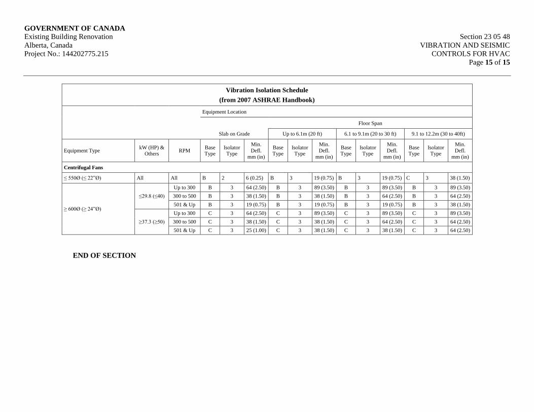
GOVERNMENT OF CANADA Existing Building Renovation Section 23 05 48
Alberta, Canada VIBRATION AND SEISMIC
Project No.: 144202775.215 CONTROLS FOR HVAC
Page 15 of 15
Vibration Isolation Schedule
(from 2007 ASHRAE Handbook)
Equipment Location
Floor Span
Slab on Grade Up to 6.1m (20 ft) 6.1 to 9.1m (20 to 30 ft) 9.1 to 12.2m (30 to 40ft)
Equipment Type kW (HP) &
Others RPM
Base Type
Isolator Type
Min.
Defl.
mm (in)
Base Type
Isolator Type
Min.
Defl.
mm (in)
Base Type
Isolator Type
Min.
Defl.
mm (in)
Base Type
Isolator Type
Min.
Defl.
mm (in)
Centrifugal Fans
≤ 550Ø (≤ 22”Ø) All All B 2 6 (0.25) B 3 19 (0.75) B 3 19 (0.75) C 3 38 (1.50)
≥ 600Ø (≥ 24”Ø)
≤29.8 (≤40)
Up to 300 B 3 64 (2.50) B 3 89 (3.50) B 3 89 (3.50) B 3 89 (3.50)
300 to 500 B 3 38 (1.50) B 3 38 (1.50) B 3 64 (2.50) B 3 64 (2.50)
501 & Up B 3 19 (0.75) B 3 19 (0.75) B 3 19 (0.75) B 3 38 (1.50)
≥37.3 (≥50)
Up to 300 C 3 64 (2.50) C 3 89 (3.50) C 3 89 (3.50) C 3 89 (3.50)
300 to 500 C 3 38 (1.50) C 3 38 (1.50) C 3 64 (2.50) C 3 64 (2.50)
501 & Up C 3 25 (1.00) C 3 38 (1.50) C 3 38 (1.50) C 3 64 (2.50)
END OF SECTION

GOVERNMENT OF CANADA Existing Building Renovation Section 23 05 53
Alberta, Canada IDENTIFICATION FOR HVAC
Project No.: 144202775.215 PIPING AND EQUIPMENT
Page 1 of 11
1. General
1.1 Scope
.1 Painting and identification of equipment, piping and related components for the
following:
.1 Fire Protection Systems
.2 Plumbing Systems
.3 Ventilation Systems
1.2 Quality Control
.1 Coordinate color coding of piping and equipment with work of Section 09 91 23 –
Interior Painting.
.2 All painting identified in this section is to be performed by Section 09 91 23 – Interior
Painting Contractor, under the direction of the Division 23 contractor.
.3 Color code mechanical equipment, piping and ductwork. Refer to Part 3 of this section.
1.3 Definitions
.1 For the purposes of this Section, the following definitions apply:
.2 Concealed: Piping, ductwork and equipment in trenches, shafts, furrings and suspended
ceilings.
.3 Exposed: Piping, ductwork and equipment in mechanical rooms or otherwise not
“concealed”.
1.4 Related Work Specified in Other Sections
.1 Submittals Division 01
.2 Interior Painting Section 09 91 23
.3 Common Work Results for HVAC Section 23 05 00
1.5 Reference Standards
.1 American Society of Mechanical Engineers (ASME)
.1 ASME A13.1-2007 Scheme for the Identification of Piping Systems
.2 Canadian Gas Association (CGA)
.1 CAN/CGA B149.1 Natural Gas and Propane Installation Code
GOVERNMENT OF CANADA Existing Building Renovation Section 23 05 53
Alberta, Canada IDENTIFICATION FOR HVAC
Project No.: 144202775.215 PIPING AND EQUIPMENT
Page 2 of 11
.3 Canadian General Standards Board (CGSB)
.1 CGSB-1-GP-12c Color Identification and Selection
.2 CAN/CGSB-1.60 Interior Alkyd Gloss Enamel.
.3 CAN/CGSB-24.3 Identification of Piping Systems
.4 National Fire Protection Association (NFPA)
.1 NFPA 13 Standard for the Installation of Sprinkler
Systems
.5 WHMIS Pictograms – Workplace Hazardous Materials Information System – GHS
Globally Harmonized System of Classification and Labeling Chemicals) – Pictograms
1.6 Delivery & Storage
.1 Deliver and store materials in accordance with Section 23 05 00 – Common Work
Results for HVAC.
1.7 Waste Management and Disposal
.1 Separate waste materials for reuse and recycling in accordance with 23 05 00 – Common
Work Results for HVAC.
1.8 Submittals
.1 Submit a schedule of pipe and equipment identification methods, materials and colors to
the Engineer for review.
2. Products
Not Applicable
3. Execution
3.1 General
.1 Perform work in accordance with CAN/CGSB-24.3 except as specified otherwise.
.2 Provide ULC and/or CSA registration plates as required by respective agency.
3.2 Identification Labels
.1 Identification Labels for all mechanical piping and ductwork systems, to include:
.1 WHMIS Pictogram (as applicable), same color as legend letters.

GOVERNMENT OF CANADA Existing Building Renovation Section 23 05 53
Alberta, Canada IDENTIFICATION FOR HVAC
Project No.: 144202775.215 PIPING AND EQUIPMENT
Page 3 of 11
.2 A lettered legend on a coloured background, defining the contents in the pipe, its
pressure and temperature and the information necessary to define the hazard.
.3 Arrows to define the direction of flow, same colour as legend letters.
.4 50mm (2”) wide black tape at each end of the label, wrapped around the entire
circumference of pipe/insulation to secure the Identification Labels.
.2 Identification Labels may be accomplished by paint, stenciling and/or factory fabricated
labels. Labels shall cover full circumference of pipe or insulation.
3.3 Location of Labels
.1 Orient labels on piping systems in visual sight lines while standing at floor levels.
.2 Locate labels as follows:
.1 Upstream of valves.
.2 Adjacent to changes in direction.
.3 Branches.
.4 Where pipes pass through walls or floors.
.5 On straight pipe runs at 6 m intervals.
.6 Where system is installed in pipe chases, ceiling spaces, shafts, or similar
confined spaces, at entry and exit points and at access openings.
.7 At beginning and end points of each run and at each piece of equipment.
.3 Adhere labels to piping/insulation. Labels to cover entire pipe circumference. Secure both
ends of labels with 50mm (2”) wide black tape around the entire pipe circumference.
3.4 Existing Identification Systems
.1 Apply existing identification system to new work.
.2 Where existing identification system does not cover for new work, use identification
system specified this section.
.3 Before starting work, obtain written approval of identification system from the Engineer.
3.5 Ductwork Identification
.1 Use 65mm high black stenciled letters with arrows indicating flow. Identify both systems
number and type of air where possible.
.1 Duct identification to be:
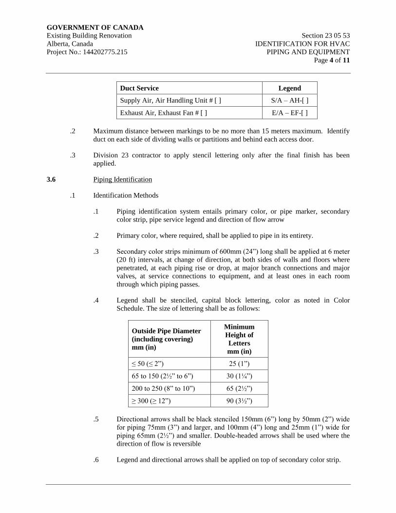
GOVERNMENT OF CANADA Existing Building Renovation Section 23 05 53
Alberta, Canada IDENTIFICATION FOR HVAC
Project No.: 144202775.215 PIPING AND EQUIPMENT
Page 4 of 11
Duct Service Legend
Supply Air, Air Handling Unit # [ ] S/A – AH-[ ]
Exhaust Air, Exhaust Fan # [ ] E/A – EF-[ ]
.2 Maximum distance between markings to be no more than 15 meters maximum. Identify
duct on each side of dividing walls or partitions and behind each access door.
.3 Division 23 contractor to apply stencil lettering only after the final finish has been
applied.
3.6 Piping Identification
.1 Identification Methods
.1 Piping identification system entails primary color, or pipe marker, secondary
color strip, pipe service legend and direction of flow arrow
.2 Primary color, where required, shall be applied to pipe in its entirety.
.3 Secondary color strips minimum of 600mm (24”) long shall be applied at 6 meter
(20 ft) intervals, at change of direction, at both sides of walls and floors where
penetrated, at each piping rise or drop, at major branch connections and major
valves, at service connections to equipment, and at least ones in each room
through which piping passes.
.4 Legend shall be stenciled, capital block lettering, color as noted in Color
Schedule. The size of lettering shall be as follows:
Outside Pipe Diameter
(including covering)
mm (in)
Minimum
Height of
Letters
mm (in)
≤ 50 (≤ 2”) 25 (1”)
65 to 150 (2½” to 6”) 30 (1¼”)
200 to 250 (8” to 10”) 65 (2½”)
≥ 300 (≥ 12”) 90 (3½”)
.5 Directional arrows shall be black stenciled 150mm (6”) long by 50mm (2”) wide
for piping 75mm (3”) and larger, and 100mm (4”) long and 25mm (1”) wide for
piping 65mm (2½”) and smaller. Double-headed arrows shall be used where the
direction of flow is reversible
.6 Legend and directional arrows shall be applied on top of secondary color strip.
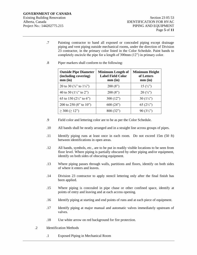
GOVERNMENT OF CANADA Existing Building Renovation Section 23 05 53
Alberta, Canada IDENTIFICATION FOR HVAC
Project No.: 144202775.215 PIPING AND EQUIPMENT
Page 5 of 11
.7 Painting contractor to band all exposed or concealed piping except drainage
piping and vent piping outside mechanical rooms, under the direction of Division
23 contractor, in the primary color listed in the Color Schedule. Paint bands to
completely encircle the pipe for a length of 300mm (12”) in primary color.
.8 Piper markers shall conform to the following:
Outside Pipe Diameter
(including covering)
mm (in)
Minimum Length of
Label Field Color
mm (in)
Minimum Height
of Letters
mm (in)
20 to 30 (¾” to 1¼”) 200 (8”) 15 (½”)
40 to 50 (1½” to 2”) 200 (8”) 20 (¾”)
65 to 150 (2½” to 6”) 300 (12”) 30 (1¼”)
200 to 250 (8” to 10”) 600 (24”) 65 (2½”)
≥ 300 (≥ 12”) 800 (32”) 90 (3½”)
.9 Field color and lettering color are to be as per the Color Schedule.
.10 All bands shall be neatly arranged and in a straight line across groups of pipes.
.11 Identify piping runs at least once in each room. Do not exceed 15m (50 ft)
between identifications in open areas.
.12 All bands, symbols, etc., are to be put in readily visible locations to be seen from
floor level. Where piping is partially obscured by other piping and/or equipment,
identify on both sides of obscuring equipment.
.13 Where piping passes through walls, partitions and floors, identify on both sides
of where it enters and leaves.
.14 Division 23 contractor to apply stencil lettering only after the final finish has
been applied.
.15 Where piping is concealed in pipe chase or other confined space, identify at
points of entry and leaving and at each access opening.
.16 Identify piping at starting and end points of runs and at each piece of equipment.
.17 Identify piping at major manual and automatic valves immediately upstream of
valves.
.18 Use white arrow on red background for fire protection.
.2 Identification Methods
.1 Exposed Piping in Mechanical Room
GOVERNMENT OF CANADA Existing Building Renovation Section 23 05 53
Alberta, Canada IDENTIFICATION FOR HVAC
Project No.: 144202775.215 PIPING AND EQUIPMENT
Page 6 of 11
.1 Apply primary color to all piping in mechanical room in accordance with
above requirements.
.2 Apply secondary banding, legend and direction of flow arrows in
accordance with above requirements.
.2 Exposed Piping in Finished Areas
.1 All exposed piping shall be painted in their entirety to match space color
scheme. Primary color requirements are waived in these areas.
.2 Apply secondary banding, legend and direction of flow arrows in
accordance with above requirements.
.3 Concealed Piping
.1 No primary color coding required.
.2 Apply secondary banding, legend and direction of flow arrows in
accordance with above requirements.
.4 Lettering and Direction of Flow
.1 Lettering: Block capitals to sizes and colors listed in CAN/CGSB 24.3..
.2 For hazardous piping system: black letters and arrows.
.3 Fire protection, other piping systems and ductwork: white letters and
arrows, unless otherwise specified.
.5 Pictograms
.1 Where required, to Workplace Hazardous Materials Information System
(WHMIS) regulations.
.6 Miscellaneous
.1 Aluminum jacketed piping shall be identified the same as concealed
piping.
.2 Exposed piping in service areas, other than mechanical rooms, shall be
identified the same as concealed piping.
.3 Additional requirements for particular piping systems:
.1 Natural gas and propane gas:
.1 Paint complete piping system yellow to
CAN/CGAB149.1.
GOVERNMENT OF CANADA Existing Building Renovation Section 23 05 53
Alberta, Canada IDENTIFICATION FOR HVAC
Project No.: 144202775.215 PIPING AND EQUIPMENT
Page 7 of 11
.2 Apply legend and flow arrows after painting.
3.7 Manufacturer’s Nameplates
.1 Provide a factory applied nameplate on each piece of manufactured equipment indicating
size, equipment name, manufacturer’s name, serial number, electrical characteristics and
performance characteristics.
.2 Provide registration plates (such as pressure vessel, ULC and CSA approved plates as
required by respective agency and as required by the specifications).
.3 Nameplates of non-Canadian made equipment shall include the name and address of the
Canadian agent providing the product.
.4 Mechanically fasten nameplates securely in a conspicuous and easily read location.
.5 Do not apply insulation or paint over nameplates.
3.8 Equipment Identification
.1 The Division 23 contractor shall provide each piece of equipment with a lamacoid plate
stating equipment name, system identification and equipment identification number.
Lamacoid plates shall be a minimum 3mm thick with black letters on white background.
Lettering to be:
.1 Terminal cabinets and control panels: 8mm high lettering
.2 Equipment in mechanical rooms and outdoors: 20 mm high lettering
.3 Equipment located elsewhere: 12mm high lettering
.2 Identify each piece of equipment with the symbol and number to be identified with record
drawing equipment name and number.
.3 Equipment which is electrically driven and is identified shall have identical nameplates at
the starter.
.4 All nameplates are to be mechanically fastened, easily visible without need to use a
ladder or extraordinary body position. Affix additional nameplates if necessary.
.5 Provide the Engineer with an example of the contents of each type of nameplate. Obtain
approval prior to engraving.
.6 Submit a complete schedule of all equipment to have identification and the symbol and
description to be engraved on the lamacoid plates or stamped brass tags.
.7 Identify as a minimum the following with engraved plastic nameplates:
.1 All mechanical equipment
GOVERNMENT OF CANADA Existing Building Renovation Section 23 05 53
Alberta, Canada IDENTIFICATION FOR HVAC
Project No.: 144202775.215 PIPING AND EQUIPMENT
Page 8 of 11
.2 VFDs
.3 Electronic thermostats, temperature sensors, humidistats, humidity sensors and
CO2 sensors.
.4 Electric starting switches, electric disconnects, remote push buttons and control
panels.
3.9 Valve Identification
.1 Division 23 contractor to provide 40mm (1½”) diameter brass tags with 20mm (¾”)
engraved lettering and brass jack chain. Secure to items with brass hooks and non-
ferrous chains or tie-wraps. Affix a tag to all valves or on piping directly adjacent to the
valve.
.2 Valve tags are not required where valves are directly adjacent to the equipment they
serve.
.3 Provide neat, typewritten valve location identification charts giving valve tag numbers,
valve service and valve location, make/model/size with or without handwheel, type of
control and normal position. Frame one copy in metal with acrylic face and mount in
equipment room. Provide additional copies for inclusion in each operating and
maintenance manual.
.4 Number valves in each system consecutively.
.5 Valve tags shall be provides as follows:
.1 Tag pneumatic/electric controls, instruments and relays. Key to control
schematic on which instruments are numbered in sequence.
.2 Tag all valves in mechanical rooms.
.3 Tag all control valves external to mechanical rooms. This includes
control valves on radiant panels, perimeter radiation and air terminal
boxes.
.4 Tag all circuit balancing valves and isolating valves external to
mechanical rooms except valves at terminal heating and cooling
equipment.
.5 Identify and tag thermostats and temperature sensors relating to terminal
unit and valve numbers.
3.10 Building Automation System Identification
.1 Utilize tags and nameplates as described for mechanical equipment and valves for
automation system components.
GOVERNMENT OF CANADA Existing Building Renovation Section 23 05 53
Alberta, Canada IDENTIFICATION FOR HVAC
Project No.: 144202775.215 PIPING AND EQUIPMENT
Page 9 of 11
.2 Use BAS mnemonics specified in BAS specification sections on tags and nameplates to
identify BAS physical points and equipment.
.3 Identify each control element (freeze stats, humidistats, discharge temperature
controllers, etc) with a laminated laser printed tag or an embossed metal band secured to
each control element.
.4 Identify the following BAS components with laminated plastic nameplates:
.1 Remote control unit (RCU) panels.
.2 Subpanels.
.3 Associated equipment panels.
.4 Panel mounted valves; identify function of each valve.
3.11 Access Door Identification
.1 Painting contractor to provide under the direction of the Division 23 contractor.
.2 Each access door for concealed equipment such as isolation valves, terminal boxes and
coils shall be provided with stenciled number, minimum height shall be 20mm (¾”).
.3 Provide neat, typewritten directory giving access door number, service and location.
Frame one copy under glass and mount in equipment room. Provide additional copies for
inclusion in each operating and maintenance manual.
3.12 Above Ceiling Equipment Markers
.1 Provide markers in T-bar and drywall type ceilings to identify locations of all dampers,
valves and equipment located above the ceilings.
.2 Locate markers on T-bar closed to equipment.
.3 Apply self-adhesive plastic dots, 15mm (½”) diameter, color coded, applied to T-bar
ceiling or access door.
.4 Color code as follows:
.1 Yellow – HVAC equipment and duct cleaning access
.2 Red – Fire, smoke and sprinkler equipment
.3 Green – Plumbing equipment and valves
.4 Blue – HVAC valves and dampers
.5 Black – Control dampers and sensors
GOVERNMENT OF CANADA Existing Building Renovation Section 23 05 53
Alberta, Canada IDENTIFICATION FOR HVAC
Project No.: 144202775.215 PIPING AND EQUIPMENT
Page 10 of 11
3.13 Site Painting
.1 Treat exposed uninsulated ductwork with a coat of zinc chromate primer. Apply one (1)
coat of anti-corrosive metal primer and two (2) coats of machinery enamel.
.2 Insulated exposed ductwork shall have one (1) coat of latex primer sealer and one (1)
coat of flat latex.
.3 Air conditioning and ventilation units, tanks, other units with galvanized finish or
stainless steel finish shall not be painted. Apply two (2) coats of machinery enamel to
units with prime coat finish.
.4 Paint exposed piping. Finish exposed uninsulated pipes and drainage lines with one (1)
coat of metal primer and two (2) coats of machinery enamel which shall be brushed out to
a thin even coat, white in color or as selected by architect. Neutralize galvanized pipes
with copper sulfate solution prior to painting. Insulated pipes shall have one (1) coat of
latex primer sealer and one (1) coat of flat latex, milk white color. Do not paint
aluminum jacketed piping except for identification.
.5 After all non-aluminum jacket piping is painted, the mechanical contractor shall direct
the painting of color bands on all piping by the painting contractor. The Division 23
contractor shall stencil letters designating the pipe service and direction of flow. The
symbol shall be finished in the color code of the mechanical specification.
.6 Steel grilles, diffusers and louvers that are primed only by the mechanical contractor shall
have final painting carried out by the painter. Colors will be selected later by the
architect from manufacturer’s standard range.
3.14 Equipment Protection and Clean-Up
.1 Ensure that new and existing equipment and surfaces are carefully covered with tarping,
or heavy duty plastic. Ensure that spills and splatter on finishes and equipment are
cleaned up totally and promptly.
3.15 Visible (Exposed) Ductwork
.1 Paint visible ductwork as directed by Architect. Refer to section 09 91 00.
.2 Paint ductwork/flexible connectors that are visible behind grilles/diffusers, matt black.
Refer to Section 09 91 00.
3.16 Pre-Painted Equipment
.1 Division 23 Contractor to repair all pre-painted equipment that has been damaged or has
faded.
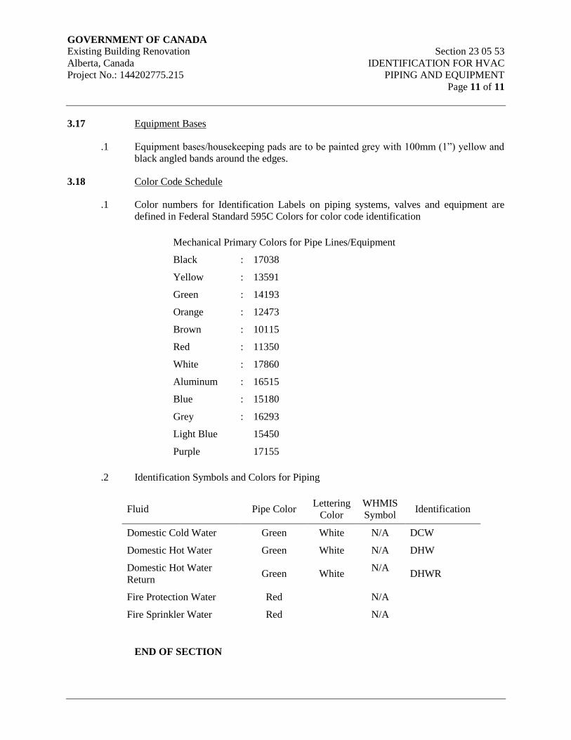
GOVERNMENT OF CANADA Existing Building Renovation Section 23 05 53
Alberta, Canada IDENTIFICATION FOR HVAC
Project No.: 144202775.215 PIPING AND EQUIPMENT
Page 11 of 11
3.17 Equipment Bases
.1 Equipment bases/housekeeping pads are to be painted grey with 100mm (1”) yellow and
black angled bands around the edges.
3.18 Color Code Schedule
.1 Color numbers for Identification Labels on piping systems, valves and equipment are
defined in Federal Standard 595C Colors for color code identification
Mechanical Primary Colors for Pipe Lines/Equipment
Black : 17038
Yellow : 13591
Green : 14193
Orange : 12473
Brown : 10115
Red : 11350
White : 17860
Aluminum : 16515
Blue : 15180
Grey : 16293
Light Blue 15450
Purple 17155
.2 Identification Symbols and Colors for Piping
Fluid Pipe Color Lettering
Color
WHMIS
Symbol Identification
Domestic Cold Water Green White N/A DCW
Domestic Hot Water Green White N/A DHW
Domestic Hot Water
Return Green White
N/A DHWR
Fire Protection Water Red N/A
Fire Sprinkler Water Red N/A
END OF SECTION

GOVERNMENT OF CANADA Existing Building Renovation Section 23 05 93
Alberta, Canada TESTING, ADJUSTING AND
Project No.: 144202775.215 BALANCING FOR HVAC
Page 1 of 14
1. General
1.1 Scope
.1 Mechanical contractor coordination with balancing agency.
.2 Balance, adjust, and test air and liquid systems and equipment and submit reports using
identical units to those shown on contract documents.
.3 Test operation of the fire dampers and combination fire/smoke dampers.
.4 Bring to the attention of the consultant, any items that are, in the opinion of the balancing
agency, installed incorrectly, prior to commencement of balancing procedures.
1.2 Quality Assurance
.1 Work specified in this section shall be performed by an Independent Agency specializing
in this type of work. Provide proof that the agency has successfully completed five
projects of similar size and scope and is a certified member of Associated Air Balance
Council, or similar association. List personnel, and their qualifications, who will be
employed during the testing and balancing period.
.2 Balancing (of both air and liquid systems) and sound level readings shall be performed by
the same agency.
.3 Balancing procedures shall be in accordance with AABC’s “National Standards for Field
Management and Instrumentation – Total System Balance”, SMACNA, ASHRAE
Standards, or other similar procedures.
.4 During the one year warranty period, the owner may request re-check or re-setting of
outlets or fans as listed in test report. Provide technicians and equipment required during
visits for seasonal adjustments.
1.3 Related Requirements
.1 Commissioning Section 01 91 00
.2 Commissioning (Cx) Plan Section 01 91 33
1.4 Related Work Specified in Other Sections
.1 Common Work Results for HVAC Section 23 05 00
1.5 Approved Agencies
.1 Contractor to submit proposed agency for Consultant and Owner approval.
.2 Provide documentation confirming qualifications and previous experience with projects
of similar size and complexity.
GOVERNMENT OF CANADA Existing Building Renovation Section 23 05 93
Alberta, Canada TESTING, ADJUSTING AND
Project No.: 144202775.215 BALANCING FOR HVAC
Page 2 of 14
1.6 Mechanical Contractor Responsibilities
.1 Bring the work to an operating state and ready for balancing, including:
.1 Clean equipment and ductwork.
.2 Install air terminal devices.
.3 Provide temporary filters in air handling equipment and carry out a rough air
balance to ensure all equipment performs required function.
.4 Replace filters with specified filters prior to final balancing.
.5 Verify lubrication of equipment.
.6 Install permanent instrumentation.
.7 Complete the "start-up" of equipment.
.8 Check rotation and alignment of rotating equipment and tension of belted drives.
.9 Set control points of automatic apparatus, check-out sequence of operation.
.10 Make available control diagrams and sequence of operation.
.11 Clean work, remove temporary tags, stickers, and coverings.
.12 Make available one (1) copy of Maintenance Manuals especially for use in
balancing.
.13 Provide Balancing Agency a complete set of mechanical drawings and
specifications.
.2 Cooperate with the Balancing Agency as follows:
.1 Make corrections as required by Balancing Agency.
.2 Allow Balancing Agency free access to site during construction phase. Inform
Balancing Agency of any major changes made to systems during construction
and provide a complete set of record drawings for their use.
.3 Provide and install any additional balancing valves, dampers, and other materials
requested by the balancing agency and/or necessary to properly adjust or correct
the systems to design flows.
.4 Provide and install revised pulleys and sheaves for rotating equipment and shave
pump impellers, as required to properly balance the systems to design flows.
Obtain requirements from balancing agency (Refer to Section 25 05 93 – Testing,
Adjusting and Balancing for HVAC Systems).

GOVERNMENT OF CANADA Existing Building Renovation Section 23 05 93
Alberta, Canada TESTING, ADJUSTING AND
Project No.: 144202775.215 BALANCING FOR HVAC
Page 3 of 14
.5 Operate automatic control system and verify set points during Balancing.
1.7 Site Visits
.1 Total of six (6) site visits shall be made to correspond with the general monthly site
meetings held by the Contractor. After each site visit, a written report shall be submitted
to the Contractor and Engineer. Site visits shall commence after the start of air and liquid
distribution work and be spread over the construction period to the start of the balancing
work.
.2 A review of the installation and access to all valves, dampers, and equipment shall be
made at the specified site visits and any additional dampers or valves required for proper
balancing shall be forwarded in writing to be reviewed by the Engineer.
.3 Allow for two (2) visits of one (1) day to site to adjust systems for seasonal changes
during warranty. Coordinate time of visits with the Owner. Submit reports to Engineer.
.4 Begin balancing after equipment start-up and testing and after systems have been
completed and are in full working order. Place systems and equipment into full operation
and continue operation during each working day of balancing.
1.8 Balancing Agenda
.1 General: Submit balancing agenda to the Engineer and commissioning contractor for
review at least sixty (60) days prior to the start of balancing work. Start balancing work
only after agenda has been approved. Include descriptive data, procedure data, and
sample forms in agenda.
.2 Descriptive Data: General description of each system including associated equipment
and different operation cycles, listing of flow and terminal measurements to be
performed.
.3 Procedure Data: Procedures for converting test measurements to establish compliance
with requirements specify type of instrument to be used, method of instrument
application (by sketch) and correction factors.
.4 Use forms approved by AABC. AABC test sheets required are as follows:
.1 Air Moving Equipment Test Sheet.
.2 Exhaust Fan Test Sheet.
.3 Diffuser and Grille Test Sheet.
.4 Duct Traverse Zone Totals Sheet.
.5 Duct Traverse Readings Sheet.
GOVERNMENT OF CANADA Existing Building Renovation Section 23 05 93
Alberta, Canada TESTING, ADJUSTING AND
Project No.: 144202775.215 BALANCING FOR HVAC
Page 4 of 14
.5 The total air and water systems shall have the AABC Field Test and Diagnosis Section I
through Section VI Form completed.
.6 At the completion of balancing the first major air system, the balancing agent shall notify
the Engineer to re-visit the site to evaluate work completed to this time. Provide the
Engineer with ten (10) business days written notice, prior to request for site visit.
1.9 Balance Report
.1 Submit (2) copies of rough balancing reports to the Engineer for review, prior to on-site
verification and acceptance of Project.
.2 Provide four (4) copies of final reports to contractor for inserting in Owner's Operating
and Maintenance Manuals as described in Section 23 05 00 – Common Work Results for
HVAC.
.3 General description of each system including associated equipment and different
operation cycles, listing of flow and terminal measurements to be performed (selection
points for proposed sound measurements).
.4 Procedure Data: Procedures for converting test measurements to establish compliance
with requirements. Specify type of instrument to be used, method of instrument
application (by sketch) and correction factors.
.5 Sample Forms: Forms showing application of procedures to typical systems.
.6 Balance Reports:
.1 Submit copies of reports described prior to final acceptance of project. Provide
copies for the consultant and for inclusion in Operating and Maintenance
Manuals.
.2 Provide reports in soft-cover, three-ring binder manuals, complete with index
page and indexing tabs and cover identification at front and side.
.3 Stamp reports by a registered professional engineer certifying adherence to
agenda, calculation procedure and final summaries.
.4 Include types, serial number and dates of calibration of instruments.
.7 System Data Reports:
.1 Reports shall include balance and equipment data listed. Report all values in
units identical to those specified and shall be shown for design values and actual
measured values.
.2 Include schematic diagrams of systems showing final damper and component
location and positioning.
GOVERNMENT OF CANADA Existing Building Renovation Section 23 05 93
Alberta, Canada TESTING, ADJUSTING AND
Project No.: 144202775.215 BALANCING FOR HVAC
Page 5 of 14
.3 Report design and final observed air capacities, velocities, etc., including outside
air and return air volumes at various damper positions.
.4 Report air temperatures at various mixing damper positions, at inlet and outlet of
all heat transfer equipment and at supply terminals.
.5 Report static pressure readings at various system operating conditions showing
total static, duct static, etc.
.6 Report equipment characteristics at various system operating conditions
including, but not limited to, motor name-plate data and actual RPM, adjustable
sheave position, fan inlet velocity, filter pressure drop, fan pitch angle,
calculation factors for air terminals, etc.
1.10 System Data
.1 Air Handling Equipment
.1 Design Data:
Total air flow rate;
Fan total static pressure;
System static pressure;
Motor kW (HP), r/min, amps, Volts, Phase;
Outside air flow rate L/s (cfm);
Fan r/min;
Fan/kW (HP);
Inlet and outlet, dry and wet bulb temperatures.
.2 Installation Data:
Manufacturer and model;
Size;
Arrangement discharge and class;
Motor type, kW (HP), r/min, voltage, phase, cycles, and load amperage;
Location and local identification data.
.3 Recorded Data:
GOVERNMENT OF CANADA Existing Building Renovation Section 23 05 93
Alberta, Canada TESTING, ADJUSTING AND
Project No.: 144202775.215 BALANCING FOR HVAC
Page 6 of 14
Supply Air Fan
Fan @ 100% Outside Air
Air flow rate;
Fan total static pressure;
System static pressure;
Fan r/min;
For Axial Fans, note blade pitch angle
Motor operating amperage;
Inlet and outlet, dry and wet bulb temperatures.
.2 Duct Air Quantities - All mains supplying more than 10% of Volume, outside air and
exhaust (maximum and minimum) major return air openings back to duct shafts.
Duct sizes;
Number of pressure readings;
Sum of velocity measurements;
Average velocity;
Duct recorded air flow rate;
Duct design air flow rate.
.3 Air Inlet and Outlets:
Outlet identification location and designation;
Manufacturers catalogue identification and type;
*Application factors;
Design and recorded velocities;
Design and recorded air flow rates;
Deflector vane or diffuser cone settings.
* (Refer to 3.1.3 for supporting information)
GOVERNMENT OF CANADA Existing Building Renovation Section 23 05 93
Alberta, Canada TESTING, ADJUSTING AND
Project No.: 144202775.215 BALANCING FOR HVAC
Page 7 of 14
2. Products
2.1 Instruments
.1 Use accurate instruments for measurements. Use only certified calibration agencies for
calibration.
.2 Provide calibration histories for each instrument. Recalibration or use of other
instruments may be requested when accuracy of readings is questionable.
3. Execution
3.1 General Procedure
.1 Permanently mark, by stick-on labels and/or fluorescent paint, settings on valves,
splitters, dampers, and other adjustment devices.
.2 Subsequent to correctional work, take measurements to verify balance has not been
disrupted or that any such disruption has been rectified.
.3 Where vane anemometer is used to measure supply, return or exhaust air grilles, AK
factors shall be determined as follows:
.1 Determine and tabulate similar sized grilles being balanced for AK schedule.
.2 Traverse all ducts serving grilles (outlined in AK schedule) to verify AK factors.
.3 AK factor from schedule must be approved by Engineer during initial review
with balancer on site. (Balancer shall include written procedure for
determination of AK factors).
.4 No flow hoods are to be used for measurement of exhaust or return air grilles.
.4 Balancing shall be performed to the following accuracies:
.1 Air - terminal outlets ±10% (outlets less than 200 L/s (425 CFM))
.2 Air - terminal outlets ±5% (outlets greater than 200 L/s (425 CFM))
.3 Air - central equipment ±5%
.5 Balancing contractor shall advise mechanical contractor of required revised pulleys,
sheaves and impeller shavings to allow proper balancing of systems.
.6 Where axial fans require blade pitch changes, this shall be the responsibility of the
balancing contractor.
.7 Check and adjust entire system approximately six months after final acceptance. Adjust
system if deviations have occurred since balance report acceptance. Submit report.
GOVERNMENT OF CANADA Existing Building Renovation Section 23 05 93
Alberta, Canada TESTING, ADJUSTING AND
Project No.: 144202775.215 BALANCING FOR HVAC
Page 8 of 14
.8 The work shall also include the following:
.1 Setting of all pressure regulating and reducing valves to operating and code
conditions.
.2 Check and setting of all relief and safety valves to code requirements.
.3 Balancing of all air flows from fans in ducts, through air outlets to design
conditions.
.4 Balancing building systems to maintain designed pressure relationships between
various areas.
.9 Test the operation of each fire damper and fire/smoke damper.
3.2 General Air System Balancing
.1 All new air systems to be balanced to show air volumes and velocities at main and branch
ducts and at all terminals. Fan volumes to be recorded at various mixed air conditions.
.2 Record system air temperatures at various mixed air conditions.
.3 Adjust air flow and terminals to eliminate objectionable air noise at terminal.
.4 Use Pitot tube transverse across entire duct area to measure air flow.
.5 Vary total air system quantities by adjustment of fan speeds.
.6 Where modulating dampers are installed, take measurements at both high and low
extremes.
.7 Balance variable volume system to maximum air flow rate with full cooling flow and to
minimum air flow rate with full heating flow.
.8 Perform balancing, adjusting, and testing with building doors and windows in their
normal operation position.
.9 The following procedure shall be adopted for central systems:
.1 Ensure dampers or volume control devices are in fully open position.
.2 Balance central apparatus to ±5% air flow.
.3 Balance branches and mains in accordance with 3.1.4.
.4 Recheck central apparatus.
.5 Balance all terminal air outlets in accordance with 3.1.4.
.6 Re-balance central apparatus to ±5%.
GOVERNMENT OF CANADA Existing Building Renovation Section 23 05 93
Alberta, Canada TESTING, ADJUSTING AND
Project No.: 144202775.215 BALANCING FOR HVAC
Page 9 of 14
.7 Recheck all air outlets.
.10 When balancing air outlets:
.1 Rough balance furthest outlets and then balance sequentially back to source.
.2 Fine balance furthest outlet back to source.
.11 Take static pressure readings and air supply temperature readings at 10 points on the
system.
.12 Make air quantity measurements in ducts by "Pitot Tube" traverse of entire cross
sectional area. Take a minimum of 16 for rectangular ducts, and 10 on each vertical and
horizontal axis for round ducts, traverse readings. If readings are inconsistent across
duct, try to obtain straight run of six (6) diameters widths upstream and re-do traverse.
3.3 Variable Volume Air System Procedure
.1 Perform air system balancing for each variable volume air system as per AABC
specification as described in the following:
.1 Check and note the following items on the supply and return fans:
.1 Proper fan rotation.
.2 Filter condition (clean and dirty, as specified).
.3 Cooling coil condition (dry and wet).
.2 Set up the system to operate with maximum return air and minimum outside air.
.3 Set all thermostats to their normal set-points allowing the terminals to operate in a
modulated position.
.4 Obtain the following preliminary data at the supply and return fans:
.1 Fan RPM.
.2 Motor current and voltage.
.3 Fan, coil(s) and filter statics.
.4 Name-plate data on the fans and motors.
.5 Check and set the fan belt tension.
.5 Measure the static pressure at the end of each major branch.
.6 Adjust the supply fan controller and/or RPM to achieve the minimum static pressure
required at the end of each branch, the return fan controller and/or RPM may also have to
GOVERNMENT OF CANADA Existing Building Renovation Section 23 05 93
Alberta, Canada TESTING, ADJUSTING AND
Project No.: 144202775.215 BALANCING FOR HVAC
Page 10 of 14
be adjusted. Monitor the branch static pressure and verify that they are above the
minimum required in steps 7 through 11.
.7 Starting at the variable volume terminal closest to the fan, set the thermostat to full
cooling.
.8 Make a preliminary measurement of the terminal l/s delivery and proportionally balance
the outlets. In co-operation with the terminal manufacturer adjust the total l/s to obtain
design delivery.
.9 Set the thermostats to full heat and measure the terminal l/s delivery. In co-operation
with the terminal manufacturer adjust the total l/s to obtain design delivery.
.10 Set the thermostat to its normal set-point.
.11 Repeat steps 7 through 10 for all variable volume controllers, working and from the fan.
.12 Set enough thermostats to full cooling to allow the supply and return fans to operate at
their maximum capacity (ie: if the supply fan is sized for total of the maximum capacity
of each terminal, all thermostats should be set to full cool. If the supply fan is sized for
diversity, enough terminals to approximate the fan capacity should be set to full cool).
.13 Measure the static pressure at the end of each major branch.
.14 Adjust the supply fan controller and/or RPM to achieve the minimum static pressure
required at the end of each branch. The return fan controller and/or RPM may have to be
adjusted also. Energy consumption is minimized by adjusting the fan RPM to obtain the
required static pressure without throttling vortex or discharge dampers.
.15 Traverse the main supply duct and return duct.
.16 Balance the return system.
.17 Balance the exhaust system.
.18 Obtain the following final data at the supply, return and exhaust fans:
.1 Fan RPM.
.2 Motor current and voltage.
.3 Fan, coil(s) and filter statics.
.4 Approximate motor sheave setting.
.5 Check and set the fan belt tension.
.19 Set all thermostats to their normal set-points and allow them to become satisfied.
GOVERNMENT OF CANADA Existing Building Renovation Section 23 05 93
Alberta, Canada TESTING, ADJUSTING AND
Project No.: 144202775.215 BALANCING FOR HVAC
Page 11 of 14
.20 Measure the static pressure at the end of each major branch and verify that it is at or
above the minimum required.
.21 Test the supply and return systems to ensure that both systems have changed capacity in
proper proportion. The mixed air plenum should maintain a negative pressure at all times
to provide adequate outside air intake.
.22 Check the following controls:
.1 Economizer system – function, calibration and damper synchronization.
.2 Face and by-pass dampers – function and calibration.
.3 High temperature limit shut-off – function and calibration.
.4 Low temperature limit shut-off – function and calibration.
.23 Set all controls to their normal set-points.
.24 Test and adjust each diffuser, grille and register to within 5% of design requirements.
.25 Identify each diffuser, grille and register as to location and area.
.26 Identify and list size, type and manufacturer of diffusers, grilles, registers and all testing
equipment. Use manufacturer’s rating on all equipment to make required calculations.
.27 In readings and test of diffusers, grilles and registers, include required m/s velocity and
test m/s velocity, and required l/s and test l/s after adjustments.
.28 In co-operation with the control manufacturer’s representative, set adjustments of
automatically operated dampers to operate as specified, indicated and/or noted.
.29 Adjust all diffusers, grilles and registers to minimize drafts in all areas.
.30 Use volume control devices to regulate air quantities only to extent that adjustments do
not create objectionable air motion or sound levels. Effect volume control only by duct
internal devices such as dampers and splitters.
.31 Vary total system air quantities by adjustment of fan speeds. Vary branch air quantities
by damper regulation.
.32 Where modulating dampers are provided, take measurements and balance at extreme
conditions. (Balance variable volume systems at maximum air flow rate - full cooling,
and at minimum air flow rate - full heating).
.33 Verify all terminal unit factory settings for maximum air flow (and minimum if
applicable). Adjust terminal unit controller if required. Record adjusted units.
.34 The final balanced condition of each area shall include testing and adjusting of pressure
conditions. Test and record building pressurization levels in variable volume systems
GOVERNMENT OF CANADA Existing Building Renovation Section 23 05 93
Alberta, Canada TESTING, ADJUSTING AND
Project No.: 144202775.215 BALANCING FOR HVAC
Page 12 of 14
throughout full range of fan delivery rates, under both heating and cooling conditions.
For multi-storey building test pressure conditions at ground, intermediate and upper
levels. Front doors, exits, elevator shafts, should be checked for air flow so that exterior
conditions do not cause excessive or abnormal pressure conditions. Document abnormal
building leakage conditions noted.
.35 Complete balancing to achieve positive building pressure unless otherwise instructed. A
positive pressure relative to outside of 10 Pa (0.04” WG) minimum and 20 Pa (0.08”
WG) maximum shall be achieved, measured with negligible outside wind velocity.
3.4 Fire Damper/Fire Stop Flap Verification
.1 Visually inspect all fire dampers and fire stop flaps:
.1 Installation is straight.
.2 Wall angles properly installed.
.3 Duct has break away connection.
.4 Fire stopping material where used is properly installed.
.5 Adequate access.
.6 Clearance between sleeve and wall.
.2 Inspect all fire damper blades and tracks prior to test firing. Sheet metal trade to clean all
dirty dampers and tracks to satisfaction of balancer.
.3 Manually remove each fusible link to ensure damper blade drops properly, then reset
damper. Mark dropped fire damper with black felt marker.
.4 Testing of 10% of the fusible links shall be performed with a suitable heat source capable
of generating sufficient heat to detonate fusible link without burning or generating carbon
deposits on the blades, frame or adjacent ductwork. Selection of links to be test dropped
to be as directed by Engineer. Retesting and resetting shall be witnessed by Engineer.
.5 If fire damper does not close properly, sheet metal trade to repair installation and
balancing agency to retest.
.6 All fire damper tests shall be witnessed by two parties, certified by Contractor and
endorsed by the testing personnel.
.7 Contact Alberta Building Code enforcement authorities in writing prior to testing each
damper and have authorities witness tests as required.
3.5 Balancing Report
.1 Submit draft copies of rough balancing reports prior to final acceptance of project.
GOVERNMENT OF CANADA Existing Building Renovation Section 23 05 93
Alberta, Canada TESTING, ADJUSTING AND
Project No.: 144202775.215 BALANCING FOR HVAC
Page 13 of 14
.2 Include types, serial number and dates of calibration of instruments.
.3 Record test data on a sepia made from the latest available revised set of mechanical
drawings and submit three (3) copies upon completion of the balancing contract for
inclusion in equipment and maintenance manuals.
.4 Submit with report, fan and pump curves with operating conditions plotted. Submit grille
and diffuser shop drawings and diffusion factors.
.5 Report shall be indexed as follows:
.1 Air
Summary
Procedure
Instrumentation
Drawings
Equipment Summary
Fan Sheets
Fan Curves
Fan Profile Data
Static Data
Air Monitoring Station Data
Traverse Data and Schedule
Terminal Unit Summary
Outlet Data Summary and Schematics (per system)
Building Schematic
Building Pressurization Data
Weather Conditions at Time of Test
Diagnostic
Millwright Reports

GOVERNMENT OF CANADA Existing Building Renovation Section 23 05 93
Alberta, Canada TESTING, ADJUSTING AND
Project No.: 144202775.215 BALANCING FOR HVAC
Page 14 of 14
END OF SECTION
GOVERNMENT OF CANADA Existing Building Renovation Section 23 07 00
Alberta, Canada HVAC INSULATION
Project No.: 144202775.215 Page 1 of 13
1. General
1.1 Scope
.1 Domestic water systems (hot, cold, recirculation), ambient to 82°C (180°F)
.2 Duct thermal insulation
.3 Duct acoustic insulation
.4 Exterior ductwork
.5 Adhesives, tie wires, tapes
.6 Recovery materials
1.2 Reference Standards
.1 American Society for Testing and Materials (ASTM)
1. ASTM B209M Specification for Aluminum and Aluminum
Alloy Sheet and Plate
2. ASTM C335 Steady State Heat Transfer Properties of Pipe
Insulation
3. ASTM C411 Hot-Surface Performance of High Temperature
Thermal Insulation
4. ASTM C423 Standard Method for Sound Absorption and
Sound Absorption Coefficients by Reverberation
Room Method
5. ASTM C449 Mineral Fiber Hydraulic Setting Thermal
Insulating and Finishing Cement
6. ASTM C533 Calcium Silicate Block and Pipe Thermal
Insulation
7. ASTM C534 Preformed Flexible Elastomeric Cellular
Thermal Insulation in Sheet and Tubular Form
8. ASTM C547 Mineral Fiber Pipe Insulation
9. ASTM C553 Mineral Fiber Blanket Thermal Insulation for
Commercial and Industrial Applications
10. ASTM C612 Mineral Fiber Block and Board Thermal
Insulation
11. ASTM C921 Practice for Determining the Properties of
Jacketing Materials for Thermal Insulation
12. ASTM C1071 Standard Specification for Fibrous Glass Duct
Lining Insulation (Thermal and Sound
GOVERNMENT OF CANADA Existing Building Renovation Section 23 07 00
Alberta, Canada HVAC INSULATION
Project No.: 144202775.215 Page 2 of 13
Absorbing Material)
13. ASTM G21 Standard of Practice for Determining Resistance
of Synthetic Polymeric Materials to Fungi
.2 American Society of Heating, Refrigeration and Air Conditioning Engineers (ASHRAE)
1. ASHRAE Standard 90.1 Energy Standard for Buildings except Low Rise
Residential Buildings
.3 Canadian General Standards Board (CGSB):
1. CAN/CGSB-51.2 Thermal Insulation, Calcium Silicate for Piping,
Machinery and Boilers
2. CAN/CGSB-51.9 Mineral Fiber Thermal Insulation for Piping and
Round Ducting
3. CAN/CGSB-51.10 Mineral Fibre Board Thermal Insulation
4. CAN/CGSB-51.11 Mineral Fibre Thermal Insulation Blanket
5. CAN/CGSB-51.12-M86 Thermal Insulating and Finishing Cement
6. CAN/CGSB-51.53 Poly (Vinyl Chloride) Jacketing Sheet for
Insulated Pipes, Vessels and Round Ducts
7. CGSB 51-GP-52Ma Vapour Barrier, Jacket and Facing Material for
Pipe, Duct and Equipment Thermal Insulation
.4 National Fire Protection Association (NFPA):
1. NFPA 255 Standard Method of Test of Surface Burning
Characteristics of Building Materials
.5 Thermal Insulation Association of Canada (TIAC)
.1 Mechanical Insulation Best Practices Guide.
.6 Underwriters Laboratories Canada (ULC)
1. CAN/ULC-S102 Standard Method of Test for Surface Burning
Characteristics of Building Materials and
Assemblies
2. CAN/ULC-S701 Thermal Insulation, Polystyrene, Boards and
Pipe
1.3 Submittals
.1 Product Data
GOVERNMENT OF CANADA Existing Building Renovation Section 23 07 00
Alberta, Canada HVAC INSULATION
Project No.: 144202775.215 Page 3 of 13
.1 Submit manufacturer’s product data in accordance with Section 23 05 00 –
Common Work Results for HVAC.
.1 Submit product data and test reports when requested to substantiate that
insulation and recovery assemblies meet flame/smoke development
ratings and performance requirements for the assembly and thickness
used.
.2 Submit information showing installed insulation and membrane products
meet the requirements of ASHRAE 90.1.
.2 Shop Drawings
.1 Submit shop drawings in accordance with Section 01 33 00 – Submittal
Procedures, and Section 23 05 00 – Common Work Results for HVAC.
.1 For each application submit an insulation schedule to include the
following information:
.1 Materials
.2 "k" value
.3 Thickness
.4 Density
.5 Finish
.6 Jacketing
.3 Submit information showing installed insulation and membrane products meet the
requirements of the National Energy Code of Canada for Buildings (NECB), 2011 and
ASHRAE 90.1-2010.
1.4 Delivery & Storage
.1 Deliver and store materials in accordance with Section 23 05 00 – Common Work
Results for HVAC.
1.5 Waste Management and Disposal
.1 Separate waste materials for reuse and recycling in accordance with Section 23 05 00 –
Common Work Results for HVAC.
1.6 Related Work Specified in Other Sections
.1 Common Work Results for HVAC Section 23 05 00
.2 Plumbing Division 22
.3 Heating, Ventilation and Air Conditioning Division 23
GOVERNMENT OF CANADA Existing Building Renovation Section 23 07 00
Alberta, Canada HVAC INSULATION
Project No.: 144202775.215 Page 4 of 13
1.7 Quality Assurance
.1 Insulation shall be installed by skilled workmen regularly engaged in this type of work.
.2 Materials shall meet fire and smoke hazard ratings as stated in this section and defined in
applicable building codes.
1.8 Product Options and Substitutions
.1 Refer to Division 01 for requirements pertaining to product options and substitutions.
.2 Alternative insulations are subject to approval. Alternatives shall provide the same
thermal resistance within 5%, at normal conditions as material specified.
1.9 Definitions
.1 For the purposes of this Section, the following definitions apply:
.1 Concealed: Piping, ductwork or equipment in trenches, shafts, furring, and
suspended ceilings.
.2 Exposed: Piping, ductwork or equipment in mechanical rooms or
otherwise not "concealed".
.3 "k" Value: Thermal conductivity of insulating material per unit of thickness
(W/m.°C).
1.10 Flame/Smoke Development Ratings
.1 Insulation materials, recovery materials, vapor barrier facings, tapes and adhesives shall
have maximum flame spread rating of 25 and maximum smoke developed rating of 50,
when tested in accordance with CAN/ULC-S102. Materials required which do not meet
this rating must be treated on site with finish which will provide necessary ratings.
.2 Insulating materials and accessories shall withstand service temperatures without
smoldering, glowing, smoking or flaming when tested in accordance with ASTM C411.
.3 ULC or ULI label or listing or satisfactory certified report form an approved testing
laboratory will be required to indicate that the fire hazard ratings for materials proposed
for used do not exceed those specified.
1.11 Job Conditions
.1 Perform work at ambient and equipment temperatures as recommended by the adhesive
manufacturer. Make good separation of joints or cracking of insulation due to thermal
movement, poor workmanship, or material defects.
GOVERNMENT OF CANADA Existing Building Renovation Section 23 07 00
Alberta, Canada HVAC INSULATION
Project No.: 144202775.215 Page 5 of 13
2. Products
2.1 Acceptable Manufacturers
1. Insulation : Owen's Corning/Fiberglas Canada Inc., Manson,
Knauf Fiberglass, Ottawa Fibre
2. Adhesives and Coatings : Bakor, 3M Company, Durodyne, Benjamin Foster
3. Sealants : Dow Corning, Tremco
2.2 General
.1 Flame proofing treatments subject to deterioration due to the effects of moisture or high
humidity are not acceptable.
.2 All adhesives, sealers, vapor coatings, etc., shall be compatible with the materials to
which they are applied and shall not deteriorate insulation material.
.3 All insulation materials shall meet Building Code Standards, and packages or containers
of such materials shall be appropriately labelled.
2.3 Hot Pipe Insulation
.1 Hot Pipe Insulation – Mineral Fiber
.1 Material: Formed rigid mineral fibre insulation sleeving to ASTM C547.
.2 "k" Value: Maximum 0.035 W/m.°C at 24°C (0.24 btu in/hr/ft2 at 75F)
.3 Service Temperature: Up to 150°C (300°F)
.4 Jacket: Factory applied general purpose jacket.
2.4 Cold Pipe Insulation
.1 Cold Pipe Insulation: Mineral Fiber:
.1 Material: Formed mineral fibre rigid insulation sleeving to ASTM C547.
.2 "k" Value: Maximum 0.035 W/m.°C at 24°C (0.24 btu in/hr/ft2 at 75F)
.3 Service Temperature: -14°C to 100°C (7°F to 212°F)
.4 Jacket: Factory applied vapor barrier jacket to CGSB 51-GP-52Ma, Type 1, with
longitudinal lap seal.
2.5 Hot Duct Insulation
.1 Hot Duct Insulation - Round and Oval:
GOVERNMENT OF CANADA Existing Building Renovation Section 23 07 00
Alberta, Canada HVAC INSULATION
Project No.: 144202775.215 Page 6 of 13
.1 Material: Flexible mineral fiber blanket insulation to ASTM C553 faced with
factory applied vapor retarder jacket to CGSB 51-GP-52Ma.
.2 "k" Value: Maximum 0.035 W/m/C at 24C (0.24 btu in/hr/ft2 at 75F)
.3 Service Temperature: 20°C to 65°C (68°F to 149°F)
.2 Hot Duct Insulation - Rectangular
.1 Material: Rigid mineral fiber insulation to ASTM C612 with factory applied
vapor retarder jacket to CGSB 51-GP-51Ma.
.2 "k" Value: Maximum 0.035 W/m/C at 24C (0.24 btu in/hr/ft2 at 75F)
.3 Service Temperature: 20°C to 65°C (68°F to 149°F)
2.6 Cold Duct Insulation
.1 Cold Duct Insulation - Round and Oval:
.1 Material: Flexible mineral fiber blanket insulation to CAN/CGSB-51.11.
.2 "k" Value: Maximum 0.035 W/m/°C at 24C (0.24 btu in/hr/ft2 at 75°F)
.3 Service Temperature: -40°C to 65°C (-40°F to 150°F)
.4 Jacket: factory applied reinforced aluminum foil vapour barrier to CGSB
51-GP-52Ma.
.2 Cold Duct Insulation - Round (Exposed to Outdoors):
.1 Material: Semi-rigid mineral fiber in roll form.
.2 "k" Value: Maximum 0.035 W/m/°C at 24C (0.24 btu in/hr/ft2 at 75°F)
.3 Service Temperature: -40°C to 65°C (-40°F to 150°F)
.4 Jacket: Factory applied reinforced aluminum foil vapor barrier to
CGSB 51-GP-52Ma.
.3 Cold Duct Insulation - Rectangular:
.1 Material: Rigid mineral fiber insulation to CAN/CGSB-51.10.
.2 "k" Value: Maximum 0.035 W/m/°C at 24C (0.24 btu in/hr/ft2 at 75°F)
.3 Service Temperature: -40°C to 65°C (-40°F to 150°F)
.4 Jacket: Factory applied reinforced aluminum foil vapor barrier to CGSB
51-GP-52Ma.
GOVERNMENT OF CANADA Existing Building Renovation Section 23 07 00
Alberta, Canada HVAC INSULATION
Project No.: 144202775.215 Page 7 of 13
2.7 Acoustic Ductwork Insulation
.1 Material: Rigid mineral fiber acoustical insulation to ASTM C1071, Type 2
.2 Density: 48 kg/m³ (minimum)
.3 Acoustic Properties: Minimum NRC of 0.70 for 25mm thickness based on Type A
mounting to ASTM C423
.4 "k" Value: maximum 0.035 W/m°C at 24°C (0.24 btu in/hr/ft2 at 75F) when tested in
accordance with ASTM C177
.5 Service Temperature: -40°C to 65°C (-40°F to 150°F)
.6 Surface Finish: Absolute roughness of exposed surface not to exceed 0.58mm (26 gauge),
coated to prevent fibre erosion at air velocities up to 25.4 m/s (5000 ft/m)
2.8 Accessories
.1 For mineral fiber insulation materials:
.1 FSK Tape: vapor barrier tape consisting of laminated aluminum foil, glass fiber
scrim and paper, with pressure sensitive self adhesive.
.2 ASJ Tape: vapor resistant tape consisting of all service jacket material with
pressure sensitive self adhesive.
.3 Adhesive: quick setting adhesive for joints and lap sealing.
.2 Lap Seal Adhesive: Quick setting adhesive for joints and lap sealing of vapour barriers.
.3 Canvas Adhesive: Dilute, washable, fire retardant lagging adhesive for cementing canvas
jacket to duct insulation.
.4 Pins: Welding pins 4mm (0.15”) diameter shaft with 35mm (1½”) diameter head for
installation through the insulation. Length to suit thickness of insulation with 35mm
(1½”) square nylon retaining clips.
.5 Thermal Insulating and Finishing Cement: To ASTM C449 mineral fiber hydraulic
setting thermal insulating and finishing cement for use up to 650°C (1200°F).
2.9 Recovery Materials
.1 Canvas: ULC listed, 220g/m² plain weave cotton fabric treated with fire retardant
lagging adhesive to ASTM C921.
.2 Aluminum: ASTM B209, 0.5mm (0.02”) thick smooth with longitudinal slip joints and
50mm (2”) end laps, 0.4mm (0.015”) thick die shaped fitting covers with factory attached
protective liner on interior surface.
GOVERNMENT OF CANADA Existing Building Renovation Section 23 07 00
Alberta, Canada HVAC INSULATION
Project No.: 144202775.215 Page 8 of 13
.3 PVC: To CAN/CGSB-51.53-95, 0.38mm (0.015”) thick for interior use and 0.57mm
(0.022”) thick for exterior use, off-white in color with one-piece premoulded fitting
covers.
.4 Black Rubber Finish: Insulation manufacturers recommended vinyl lacquer type coating.
3. Execution
3.1 Installation - General
.1 Do not install insulation until after the required piping, ductwork and equipment tests
have been completed, witnessed and certified.
.2 Ensure surface is clean and dry prior to installation. Ensure insulation is dry before and
during application. Finish with systems at operating conditions, where possible.
.3 Install in accordance with TIAC National Standards and manufacturer’s
recommendations.
.4 Ensure insulation is continuous through floor and wall sleeves etc. Pack around piping
and ducts with fireproof self-supporting insulation materials, properly sealed.
.5 Finish insulation neatly at hangers, supports and other protrusions.
.6 Install insulation at ambient temperatures within acceptable temperature ratings for tapes,
sealants and adhesives.
.7 Apply insulation to provide smooth and even finish, uniform diameter, no sagging,
wrinkling, etc.
.8 A complete moisture and vapor seal shall be provided wherever insulation terminates
against metal hangers, anchors and other projections through insulation and cold surfaces
for which vapor seal is specified.
3.2 Installation – Pipe Insulation
.1 On vertical piping with diameters 25mm (1”) and larger, use insulation supports welded
or bolted to pipe directly above lowest pipe fitting. Repeat supports on 4.5m (14 ft)
centers and at each valve and flange.
.2 Tightly fit insulation sections to pipe to make smooth and even surfaces. Cut insulation
for proper fit where weld beads protrude. Bevel away from studs and nuts to allow their
removal without damage to insulation. Trim closely and neatly around extending parts of
pipe saddles, supports, hangers, clamp guides and seal with insulating/finishing cement.
3.3 Installation – Duct Insulation
.1 Insulated in their entirety are all emergency generator ventilation, ductwork, all
combustion air and relief air ductwork, all exhaust air ductwork for a distance of 5m (16
ft) from the exterior walls or openings, ductwork carrying hot or cold conditioned air and
outside air ductwork.
GOVERNMENT OF CANADA Existing Building Renovation Section 23 07 00
Alberta, Canada HVAC INSULATION
Project No.: 144202775.215 Page 9 of 13
.2 Unless otherwise indicated, do not insulate ducts carrying air at room ambient
temperature, exhaust air ductwork except as noted above, return air ductwork, relief air
ductwork and ductwork fitted with an approved acoustic thermal lining.
.3 Do not insulate ductwork with external thermal insulation where acoustic duct insulation
is specified or indicated.
.4 Add extra thickness of insulation at standing seams, flanged joints and any other duct
protrusions. Adhere jacket lap joints with an adhesive which will be guaranteed to
maintain the adhesion under all conditions.
.5 Ductwork carrying outside air must be insulated completely so there is no break in either
the insulation thickness or vapor barrier.
.6 Provide recovering jackets on exposed insulation throughout, including equipment
rooms. Insulation located in crawl spaces, shafts and suspended ceiling spaces is not
considered exposed. Make smooth any uneven insulated surface before recovering.
.7 Cover insulation exposed to outdoors with aluminum jacket secured with aluminum
bands on 200mm (8”) centers. Longitudinal slip joints, lap circumferential joints 75mm
(3”) minimum and seal all joints with compatible waterproof lap cement.
.8 Where duct velocities exceed 10m/s (2000ft/m), cover insulation with 0.8mm perforated
galvanized steel with 24% free area.
.9 Locate insulation or cover seams in least visible locations. Locate seams on ductwork in
ceiling spaces on the underside of the duct.
.10 Stagger butt joints where multi-layered insulation is used.
.11 Butt duct insulation at top of duct. Stagger all joints where more than one layer of
insulation is used. Tape all insulation joints neatly.
.12 Straps or twin ties used to secure insulation shall not unduly compress the insulation.
Sagging of duct insulation is also not allowed.
3.4 Hot Pipe Insulation Application
.1 Apply mineral fiber insulation when pipe surface temperatures are 50°C to 60°C (122°F
to 140°F).
.2 Apply mineral fiber insulation and recovery over full length of pipe without penetration
of hangers, interruption at sleeves and fittings. Seal butt joints with 100mm (4”) wide
ASJ tape.
.3 Terminate mineral fiber insulation at each end of unions and flanges. Trowel finishing
cement into bevel.
.4 Cover fittings and valves with equivalent thickness of finishing cement. Apply finishing
cement over exposed fittings and valves before applying canvas recovering. Insulate with
tightly placed flexible insulation and apply PVC fitting covers.
GOVERNMENT OF CANADA Existing Building Renovation Section 23 07 00
Alberta, Canada HVAC INSULATION
Project No.: 144202775.215 Page 10 of 13
.5 Cut mineral fibre insulation layers straight on 10m (32 ft) centers with 25mm (1”) gap to
allow for expansion between terminations. Pack void tightly with insulation and protect
joints with aluminum sleeves.
.6 Seal black rubber insulation butt joints and seams with black rubber insulation adhesive.
.7 Recover exposed mineral fiber insulated piping with PVC.
.8 Recover mineral fibre insulated piping exposed to outdoors with waterproof aluminum
jacket.
.9 Do not insulate the following piping system components:
.1 Unions, flanges, strainers, expansion joints, flexible piping connectors.
.2 Valve bonnets on domestic water systems.
.3 Drains, plugs and caps.
3.5 Cold Pipe Insulation Application
.1 Apply vapor retardant mineral fiber insulation and recovery over full length of pipe
without penetration of hangers, interruption at sleeves and fittings. Apply adhesive to
ends of butt joints and seal joint seams with 100mm (4”) wide strips of joint tape.
.2 Insulate complete system including valves, unions, flanges, strainers, drains, caps and
fittings. Cover fittings and valves with equivalent thickness of finishing cement. Cover
finishing cement with open mesh glass cloth and vapor retardant adhesive. Seal lap joints
with 100% coverage of joint tape and seal the assembly with vapor retardant adhesive.
Alternatively, insulate with tightly placed flexible insulation and apply reinforcing
membrane embedded in vapor retardant coating and apply PVC fitting covers.
.3 Recover exposed mineral fiber insulated piping with PVC.
.4 Recover mineral fiber insulated piping exposed to outdoors with aluminum.
.5 Coat exposed black rubber insulation with two coats of black rubber finish material.
3.6 Hot Duct Insulation Application
.1 Adhere insulation to round and oval ductwork with contact adhesive applied in 150mm
(6”) wide strips on 400mm (16”) centers. Band on outside with wire until adhesive has
set.
.2 Butt insulation and seal joints with lap seal adhesive; cover joint ASJ tape.
.3 Secure rigid insulation on rectangular ducts with 50% area coverage using contact
adhesive, impale on pins located 400mm (16”) on centre, secure in place with retaining
clips.

GOVERNMENT OF CANADA Existing Building Renovation Section 23 07 00
Alberta, Canada HVAC INSULATION
Project No.: 144202775.215 Page 11 of 13
.4 Butt rigid insulation on rectangular ducts and seal joints with lap seal adhesive; cover
joints with 100mm (4”) strips of open mesh cloth imbedded between two coats of lap seal
adhesive.
3.7 Cold Duct Insulation Application
.1 Adhere mineral fiber insulation to round and oval ductwork with adhesive applied in
150mm (6”) wide strips on 400mm (16”) centers. Band on outside until mastic sets then
remove bands.
.2 Butt mineral fiber insulation and seal joints with lap seal adhesive; cover joint with FSK
tape.
.3 Secure rigid insulation on rectangular ducts with 50% area coverage of adhesive and
impale on pins located 400mm (16”) on centre and secure in place with the retaining
clips.
.4 Butt rigid insulation on rectangular ducts and seal joints with lap seal adhesive; cover
joints with 100mm (4”) strips of open mesh cloth imbedded between two coats of lap seal
adhesive.
3.8 Acoustic Duct Insulation Application
.1 Do work in accordance with recommendations of SMACNA duct liner standards as
indicated in SMACNA HVAC Duct Construction Standards, Metal and Flexible, except
as specified otherwise.
.2 Install in accordance with manufacturer’s recommendations, and as follows:
.1 Fasten to interior sheet metal surface with 100% coverage of adhesive.
.2 In addition to adhesive, install weld pins not less than 2 rows per surface and not
more than 425mm (17”) on centers.
.3 Seal butt joints, exposed edges, weld pin and clip penetrations and damaged areas of liner
with joint tape and sealer. Install joint tape in accordance with manufacturer’s written
recommendations, and as follows:
.1 Bed tape in sealer.
.2 Apply two coats of sealer over tape.
.4 Replace damaged areas of liner at discretion of the Engineer.
.5 Protect leading and trailing edges of duct sections with sheet metal nosing having 15mm
(½”) overlap and fastened to duct.
3.9 Exposed Ducts
.1 Make smooth any uneven insulated surface before recovering.
GOVERNMENT OF CANADA Existing Building Renovation Section 23 07 00
Alberta, Canada HVAC INSULATION
Project No.: 144202775.215 Page 12 of 13
.2 Finish exposed ducts with canvas jacket suitable for paint finish.
.3 Finish ducts exposed to outdoors with aluminum jacket. Caulk all joints on jacket for
weather tight finish. Locate longitudinal joints in least weather exposed position.
3.10 Duct Insulation
.1 Insulated in their entirety are all combustion air and relief air ductwork, all exhaust air
ductwork for a distance of 5m (16 ft) from the exterior walls or openings, ductwork
carrying hot or cold conditioned air and outside air ductwork.
.2 Unless otherwise indicated, do not insulate ducts carrying air at room ambient
temperature, exhaust air ductwork except as noted above, return air ductwork, relief air
ductwork and ductwork fitted with an approved acoustic thermal lining.
.3 Add extra thickness of insulation at standing seams, flanged joints and any other duct
protrusions. Adhere jacket lap joints with an adhesive which will be guaranteed to
maintain the adhesion under all conditions.
.4 Ductwork carrying outside air must be insulated completely so there is no break in either
the insulation thickness or vapor barrier.
.5 Provide recovering jackets on exposed insulation throughout, including equipment
rooms. Insulation located in crawl spaces, shafts and suspended ceiling spaces is not
considered exposed. Make smooth any uneven insulated surface before recovering.
.6 Cover insulation exposed to outdoors with aluminum jacket secured with aluminum
bands on 200mm (8”) centers. Longitudinal slip joints, lap circumferential joints 75mm
(3”) minimum and seal all joints with compatible waterproof lap cement.
.7 Where duct velocities exceed 10m/s (2000ft/m), cover insulation with 0.8mm perforated
galvanized steel with 24% free area.
3.11 Insulation Installation Thickness Schedule – Piping
Piping Pipe Sizes
mm (in)
Insulation
Thickness
mm (in)
Recovery
Jacket
1. Domestic Cold Water
Piping
40 (1½”) & under
50 (2”) & over
15 (½”)
25 (1”)
Canvas
2. Domestic Hot Water
Supply & Recirculation
Piping
50 (2”) & under
65 (2½”) & over
25 (1”)
40 (1½”)
Canvas
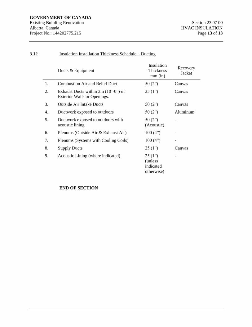
GOVERNMENT OF CANADA Existing Building Renovation Section 23 07 00
Alberta, Canada HVAC INSULATION
Project No.: 144202775.215 Page 13 of 13
3.12 Insulation Installation Thickness Schedule – Ducting
Ducts & Equipment
Insulation
Thickness
mm (in)
Recovery
Jacket
1. Combustion Air and Relief Duct 50 (2”) Canvas
2. Exhaust Ducts within 3m (10’-0”) of
Exterior Walls or Openings.
25 (1”) Canvas
3. Outside Air Intake Ducts 50 (2”) Canvas
4. Ductwork exposed to outdoors 50 (2”) Aluminum
5. Ductwork exposed to outdoors with
acoustic lining
50 (2”)
(Acoustic)
-
6. Plenums (Outside Air & Exhaust Air) 100 (4”) -
7. Plenums (Systems with Cooling Coils) 100 (4”) -
8. Supply Ducts 25 (1”) Canvas
9. Acoustic Lining (where indicated) 25 (1”)
(unless
indicated
otherwise)
-
END OF SECTION
GOVERNMENT OF CANADA Existing Building Renovation Section 23 09 00
Alberta, Canada INSTRUMENTATION AND CONTROL
Project No.: 144202775.215 FOR HVAC
Page 1 of 15
1. General
1.1 Scope
.1 Provide all materials and services as documented within these specifications and as
required to furnish a complete and fully operational DDC Building Automation System
(BAS) to monitor and control the building systems referred to in this specification.
.2 The work includes the supply and installation of DDC controllers, instrumentation,
control devices, conduit, wiring, tubing and other devices as necessary to provide a
complete system of BAS controls, compliant with these specifications.
.3 Supply, install and configure all software, programming and databases; set up equipment
operating schedules; and perform system activation functions as identified within these
specifications, to provide a complete and fully operational BAS.
.4 Provide:
.1 Submittals,
.2 System Documentation,
.3 Acceptance Testing, and
.4 Instructions to Owners
1.2 Related Work
.1 Instrumentation and Control Devices for HVAC Section 23 09 13
.2 Sequence of Operations for HVAC Controls Section 23 09 93.1
.3 Point Schedules for HVAC Controls Section 23 09 93.2
1.3 Work by Others
.1 Distribution and installation of wells, flow insertion fittings, motorized valves and
motorized dampers into the piping systems.
1.4 Quality Assurance
.1 Provide a complete system of BAS controls for mechanical systems by specialty BAS
firms having proof of completing three (3) projects of similar size.
.2 The BAS equipment shall be of one manufacturer throughout and shall have service for
the system from manufacturer’s factory authorized service, resident in the City of
Edmonton, Red Deer or Calgary.

GOVERNMENT OF CANADA Existing Building Renovation Section 23 09 00
Alberta, Canada INSTRUMENTATION AND CONTROL
Project No.: 144202775.215 FOR HVAC
Page 2 of 15
.3 Software engineering and support shall be resident in the City of Edmonton, Red Deer or
Calgary.
1.5 Shop Drawings
.1 Submit shop drawings in accordance with Section 23 05 00 – Common Work Results for
HVAC and with the requirements outlined below.
.2 Submit the shop drawings and technical data describing the proposed system within 90
days after award of the BAS contract. Provide sufficient detail to enable the consultant to
evaluate the proposed system and determine whether the requirements of the
specification will be met.
.1 Schematic of system architecture indicating the type and location of all digital
controllers, the major system equipment monitored and controlled by each panel
and how the controllers are to be networked.
.2 The proposed digital I/O points list including at a minimum the point mnemonic,
point description, controller number and controller I/O point number.
.3 Equipment schedule for all hardware, valves, dampers, field instrumentation,
input/output devices, transducers and actuators.
.4 Technical description and specifications for the primary and sub-networks.
.5 Schematic diagram for each mechanical system showing all input/output points,
wiring diagrams for all I/O points and a written detailed operational description
of control sequences. For terminal equipment controllers, submission of field
point wiring diagrams for each type is adequate.
.6 Engineering/technical data and maintenance information for each system
component, including sizing and arrangements as requested. Include calculations
for control valve selections.
.3 Shop drawings are to be submitted in an organized fashion complete with table of
contents, tab sheets and sequentially numbered pages to enable easy location of
information. This also applies to component data sheets.
.4 Component data sheets shall be organized by device type with tab sheets for each section
i.e. Controllers, Digital Input devices, Digital output devices, Analog input devices,
Analog output devices.
.5 The table of contents for component data sheets must indicate product description,
specification I/O device type or specification section, and page number.
.6 Component specification sheets that include more than one product shall be clearly
marked to identify the applicable product(s), options and specifications.

GOVERNMENT OF CANADA Existing Building Renovation Section 23 09 00
Alberta, Canada INSTRUMENTATION AND CONTROL
Project No.: 144202775.215 FOR HVAC
Page 3 of 15
.7 Submit copies of the complete shop drawings to the consultant for review and approval.
Partial submissions may be accepted depending on the detail and acceptance by the
Consultant. Provide additional copies of the complete approved shop drawings with the
O&M Manuals.
.8 Within 120 days after award of the contract submit printed copies of all dynamic graphic
displays, proposed calibration check sheets.
.9 Within 180 days after award of the contract submit two (2) draft Operating and
Maintenance manuals as specified in this section under System Documentation.
.10 BAS shop drawings shall be based on approved mechanical equipment shop drawings.
The Mechanical Contractor is to provide approved mechanical equipment shop drawings
to the BAS Contractor.
1.6 Owner Orientation
.1 Formal training sessions shall commence only after "as-built" drawings have been
completed, reviewed and approved by the Engineer.
.2 Individuals who have had specific training as an instructor shall conduct training
sessions.
.3 All training sessions shall include training materials and shall follow a documented
course outline.
.4 A copy of the training materials, which shall include a detailed course outline, shall be
submitted to the Engineer for approval three weeks prior to commencing any training
sessions.
.5 Any training conducted without prior approval of the Engineer shall be repeated at the
discretion of the Engineer and/or will not count toward the contractors training
obligations.
.6 The BAS contractor shall provide three weeks written notice to the Engineer and building
Owner prior to commencing formal training sessions.
.7 The BAS contractor shall provide three (3) complete sets of training manuals to the
Owner prior to commencing of the training session, plus one manual to the Engineer.
.8 Provide for operator training according to the following schedule.
.1 A one (1) day system and component familiarization seminar/workshop during
the first week of trial usage.
.2 A one (1) day seminar/workshop the week before the 7-day acceptance test
covering all aspects of system use as follows:
.1 Operation of hardware components

GOVERNMENT OF CANADA Existing Building Renovation Section 23 09 00
Alberta, Canada INSTRUMENTATION AND CONTROL
Project No.: 144202775.215 FOR HVAC
Page 4 of 15
.2 System software configuration
.3 User/system interaction
.4 Calibration of sensors and system
.5 Trouble shooting of system and components
.6 Preventative maintenance
.3 A one (1) day review workshop at one month after system acceptance.
1.7 Warranty
.1 Include warranty provisions identified in the specifications.
.2 In addition to the warranty in item .1, provide a two (2) year warranty on all items
provided under this contract including but not limited to all equipment, wiring and
software. The warranty period shall commence on the date of final written acceptance of
the BAS system.
.3 Provide on site service including all labor, materials and software to maintain the
complete control system in optimal functioning condition during the warranty period.
.4 Perform preventive maintenance (PM) during the warranty period.
.5 In addition to warranty call backs provide two (2) service and calibration inspections of a
minimum four (4) of hours duration each. These calls will be initiated by the Owner.
.6 The overtime premiums for weekend and overtime service calls shall be clearly identified
within your proposal.
.7 The BAS contractor shall supply and install at no cost all system software updates and
upgrades occurring up to 2 months prior to the expiration of the warranty period.
.8 Maintain a service log on site of all control system maintenance activities during the
warranty period.
1.8 System Activation
.1 Submit control calibration and point verification check sheets to the Engineer for
approval prior to any calibration of devices or end to end point verification commences.
Check sheets to include:
.1 Controller identification number
.2 Controller input/output point number
.3 Control point mnemonic
GOVERNMENT OF CANADA Existing Building Renovation Section 23 09 00
Alberta, Canada INSTRUMENTATION AND CONTROL
Project No.: 144202775.215 FOR HVAC
Page 5 of 15
.4 A complete concise English description of each point
.5 Device controlled
.6 Interlock devices
.7 Measured and displayed analog input values
.8 Analog Output zero and full scale verification
.9 End to End verification for all points
.10 Wire labels verification
.11 Device tag verification
.12 Date of verification
.13 Initials of person performing verification
.2 Submit sample control loop trend log plot, of the type to be used for demonstrating
control loop tuning, to the Engineer for approval.
.3 Verify that each hardware component has been properly installed as recommended by the
manufacturer and is functioning correctly.
.4 Calibrate all devices including sensors, transmitters, transducers, current relays, valve
actuators, damper motors, etc., verifying that end to end calibration accuracy as specified
has been achieved.
.5 Ensure tight shut off and fail safe operation of valves and dampers. Hysteresis shall not
be greater than 5% of the operating range.
.6 Set damper linkages, static pressure/volume controls as required.
.7 Set up run time capture for each digital input point.
.8 Set up alarm point for each digital input/output pair, with delay before alarm is
annunciated.
.9 Set up deviation alarm for each control loop measured variable input with appropriate
alarm interlocks, dead-bands and time delays.
.10 Set up high and low alarm limit points for analog input points as shown on the point list.
.11 Set up zero scale and full scale alarms for each analog input to alarm point failures.
GOVERNMENT OF CANADA Existing Building Renovation Section 23 09 00
Alberta, Canada INSTRUMENTATION AND CONTROL
Project No.: 144202775.215 FOR HVAC
Page 6 of 15
1.9 Acceptance Testing
.1 A final operational acceptance test of seven consecutive days shall be conducted on the
complete and total installed and operational control system to demonstrate that it is
functioning properly in accordance with the specifications.
.2 The correct operation of all monitored and controlled points shall be demonstrated as
well as the operation and capabilities of all sequences, reports, specialized control
programs and algorithms, diagnostics and all other software. Specific testing shall include
but not be limited to:
.1 Power Failure Restart.
.2 Outside Air Temperature Reset Schedules
.3 Night Setback
.4 Free Cooling
.5 Mechanical Cooling
.6 Mechanical Heating
.3 In the event of the failure of function, during the test, of any of the hardware components
or software application or routines, the test will recommence and run until seven failure-
free test days have occurred.
.4 Prior to conducting the final operational acceptance testing, submit to the Engineer:
.1 Completed calibration and verification check sheets including airflow station
calibration sheets.
.2 Hard copy and electronic copy on CD of final data base listings.
.3 If electronic copy of final database listing is not in Microsoft Word, Excel or
Access format, provide a final points list to the Engineer in either Microsoft
Word, Excel, or Access format.
.4 Hardcopy of all system Graphics.
.5 A signed declaration stating that all work has been completed or identifying any
outstanding deficiencies and the anticipated completion date(s).
.5 After successful completion of the acceptance test, the Engineer will issue written
acceptance of the control system.
.6 For all systems prior to substantial completion the BAS contractor shall successfully
demonstrate the response to
.1 All fire alarm interlocks, shut-down sequences and fire control strategies

GOVERNMENT OF CANADA Existing Building Renovation Section 23 09 00
Alberta, Canada INSTRUMENTATION AND CONTROL
Project No.: 144202775.215 FOR HVAC
Page 7 of 15
.2 All power failure interruptions
.7 The initiation of the Fire Alarm system into alarm mode and simulation or tripping of the
main power feeders shall be performed by others.
1.10 System Documentation
.1 Operating and Maintenance Manuals
.1 The BAS Operation and Maintenance Manuals shall contain operational, product
data, cleaning and maintenance information on all products and equipment
supplied as part of this projects BAS. The final Manuals shall accompany the
Project Record Drawings and shall be in place prior to substantial performance.
.2 Submit a draft Manual for format review three (3) months after award of
Contract and three (3) Manuals of Documentation for interim submission at 75%
construction. Draft Manuals are to be complete in all aspects less control
programming. Interim submission is to include all control shop drawings,
programming and system descriptions. Draft and Interim Manuals are to be
submitted in 3 ring binders. Final Manuals to be in catalogue type binder.
.3 Each manual shall be 215 mm x 280 mm capacity extension type Catalogue
Binder bound in heavyweight fabricord, colour to be reviewed with the Owner
prior to order and hot stamped in white lettering front and spine.
.4 The spine and front face of the binder shall be lettered with the following:
.1 Full identification title of the project
.2 Building Automation System
.3 Operation and Maintenance Manual
.4 Set X of Y
.5 Volume X of Y
.5 The manual shall be arranged according to the following format. Utilize colour
coded laminated mylar plastic divider tabs with headings according to section.
.1 Table of Contents
.2 Introduction
.3 Control System Design
.4 Building System Descriptions
.5 DDC Panel Layout

GOVERNMENT OF CANADA Existing Building Renovation Section 23 09 00
Alberta, Canada INSTRUMENTATION AND CONTROL
Project No.: 144202775.215 FOR HVAC
Page 8 of 15
.6 Shop Drawings
.7 Equipment Schedules
.8 Certification and Testing
.9 Product Manuals
.10 Maintenance
.11 Software & Certificates
.6 On the first page of each binder, before the table of contents identify the
following:
.1 Prime Consultant: name, address, telephone number.
.2 Contractor: name, address, telephone number.
.3 Subcontractors: name address, telephone number.
.7 Table of Contents
.1 Include in each binder a table of contents that provides an index in order
of appearance of all sections and subsections within the manual.
.8 Introduction
.1 Provide a written explanation of the layout of the manual.
.2 List all other control system manuals submitted for this project including
all software manuals and hardware manuals. Identify the quantities of
each manual provided.
.9 Control System Design
.1 Design Intent
.1 Explain, in this section, the design intent and give a system
overview which outlines the relationships between the hardware,
operating system, control software and other control
components.
.2 Provide a detailed description of all parts, components and
software in the system.
.3 Describe the system architecture. Provide a system
configuration schematic with the location, type and model of all
control panels, work stations, remote access modems, etc. and
GOVERNMENT OF CANADA Existing Building Renovation Section 23 09 00
Alberta, Canada INSTRUMENTATION AND CONTROL
Project No.: 144202775.215 FOR HVAC
Page 9 of 15
identify the major equipment monitored and controlled by each
panel.
.4 The schematic must identify network communication protocols
and communication speeds between all control panels and
indicate BACnet compatibility where applicable.
.5 Identify the number of controllers that can be added to each
network and sub-network and any maximum distance between
controllers or maximum length of network without the need to
add additional communication devices.
.6 Identify all software products provided including third party
software. This shall include but not be limited to all operator
workstation, graphics, controller and laptop software. For each
product, indicate the number of software licenses provided, the
name of the respective vendor and any software protection
devices required. Indicate the number of software protection
devices provided.
.2 Operations
.1 Provide an overview of the building automation system
operations. Include basic instruction on:
.1 System access
.2 Alarms management (including, how and where alarms
are annunciated, after-hours reporting of critical alarms,
etc.)
.3 Commonly used reports
.4 Laptop, local and remote system access and
.5 Basic trouble shooting directions.
.2 These instructions are to provide a basic understanding of the
system operations and are to reference specific areas of the
software manuals for further detailed instructions.
.3 Provide detailed back-up and data recovery procedures including
recommended frequencies and data to be backed up. Here again
refer to specific areas of product manuals where appropriate.
Provide sample back-up log sheets.
.10 Building System Descriptions
GOVERNMENT OF CANADA Existing Building Renovation Section 23 09 00
Alberta, Canada INSTRUMENTATION AND CONTROL
Project No.: 144202775.215 FOR HVAC
Page 10 of 15
.1 System Design intent - Explain, in this section, the design intent and give
a system overview which outlines the system components and the
intended system function.
.2 Provide a schematic, control sequences, wiring diagram, device list and
points list for each building system controlled by the BAS.
.3 Control sequences shall identify start-up and shut-down sequences,
control loop set-points, reset schedules, system interlocks, etc.
.4 As built record drawings in 11” X 17” format, folded to fit into the O&M
binders may be used to provide part or all of the information required for
this section.
.11 DDC Panel Layout
.1 Provide as-built panel layout sheets and include locations of all panels.
.2 Include a panel points list that identifies each point name with concise
English description and termination point. Identify panel spare points.
.3 Identify power source for each panel including emergency/normal, UPS,
panel number and circuit number.
.12 Shop Drawings
.1 Insert in this section all approved shop drawings organized in the format
specified in section 23 05 00 – Common Work Results for HVAC.
.13 Equipment Schedules
.1 Provide an equipment schedule for all hardware provided including
valves, dampers, actuators, controllers, transducers, input/output devices
and other instrumentation.
.14 Certification and Testing
.1 Provide final copies of all completed calibration and verification check
sheets including all airflow station calibration check sheets.
.15 Product Manuals
.1 Include in this manual or within product, user manuals and technical
manuals, complete and detailed instruction on the use, setup and support
of all control system software and hardware provided under this project.
.2 Provide detailed instructions on set-up and user operations including but
not limited to system access, navigation, alarms, trending, historical
trending, reporting and trouble shooting.
GOVERNMENT OF CANADA Existing Building Renovation Section 23 09 00
Alberta, Canada INSTRUMENTATION AND CONTROL
Project No.: 144202775.215 FOR HVAC
Page 11 of 15
.3 Provide complete detailed instruction on database structure, set-up,
initialization, expansion and editing.
.4 Provide complete detailed instruction to enable creation, modification
and implementation of control sequences.
.16 Maintenance
.1 Provide a description in this section of maintenance procedures for all
equipment and systems, as defined in this specification, including a
schedule for recommended planned and preventative maintenance work
items and intervals.
.2 Include a preventative maintenance program complete with suggested
check list sheets.
.3 Provide a list of resources to call upon for maintenance and servicing of
equipment which includes name, address and phone numbers for supplier
and service contact for each piece of equipment.
.4 Include in this section a complete set of as-built drawings if not included
elsewhere in this manual.
.5 Certification, guarantee, warranty.
.17 Software & Certificates
.1 Provide original copies of all software distribution media on CDs
inserted into vinyl page holders that are designed for 3 ring binders. The
originals are to be provided in “Set 1” of these O&M manuals and back-
up copies are to be provided in “Set 2”.
.2 Provide software registration certificates, or other documents that verify
authenticity of software.
.3 Provide back-up copies of entire system at the time of system turn over
on CDs in vinyl CD page holders designed for 3 ring binders. Backup to
include complete control sequence source code.
1.11 Record Drawings
.1 Before the certification of substantial performance will be issued the contractor must
provide the Engineer with record drawings as follows:
.1 One electronic copy of record drawings in AutoCAD version 2000 or Visio
format.
.2 Four (4) copies of as-built white prints in 280mmx432mm (8½” x 17”) capacity
blue binders bound in heavy fabricated, hot stamped in white lettering front and
GOVERNMENT OF CANADA Existing Building Renovation Section 23 09 00
Alberta, Canada INSTRUMENTATION AND CONTROL
Project No.: 144202775.215 FOR HVAC
Page 12 of 15
spine. Each is to be identified As-Built Drawings and permanently numbered 1
to 4.
.3 The spine shall be lettered with the full identification title of the project and the
front face shall be lettered with the following on the respective binders:
.1 Full identification title of the project
.2 Prime Consultant and Sub-Consultant - full identification
.3 Prime Contractor - full identification
.4 Mechanical Contractor - full identification
.4 Maintain an accurate record of all deviations and changes on a record drawing set
of prints. Such record is to be maintained on a day-to-day basis.
.5 Maintain as-built data on the data gathering and automatic control equipment
schedule and panel schedules.
2. Products
2.1 Approved Contractors
.1 Tenders on the following will be accepted:
.1 Siemens Building Systems – APOGEE product
.2 Johnson Controls – Metasys product
.3 ESC Automation – Delta Controls product
.4 Serv-All – Reliable Controls
.2 Alternates to these approved control system products can be submitted as a separate price
from the base system specified.
2.2 General
.1 Provide control system components consisting of thermostats, control valves, dampers,
actuators, indicating devices, and interface equipment required to operate mechanical
equipment and perform functions specified.
.2 Provide all materials and labor required to connect control components.
2.3 BAS Architecture
.1 The BAS system shall be native BACnet, utilizing BACnet BTL approved modules and
incorporating BACnet on all primary and secondary communication networks.
GOVERNMENT OF CANADA Existing Building Renovation Section 23 09 00
Alberta, Canada INSTRUMENTATION AND CONTROL
Project No.: 144202775.215 FOR HVAC
Page 13 of 15
.2 The BAS shall be comprised of a network of interoperable, stand-alone digital
controllers, operator work stations, server, graphical user interface software, network
devices and other devices as specified herein.
.3 The BAS shall incorporate the ability to access all user interface functions as specified
within these documents using standard internet browsers. Operator access to the BAS
shall not require any proprietary operator interface or configuration software to be loaded
on the respective PC and access shall only be limited by password.
.4 Provide for access to the BAS system by five (5) concurrent users, whether in the
building or by Internet utilizing a standard web browser.
.5 The BAS system shall incorporate BACnet native devices and they shall be
ANSI/ASHRAE 135-2012 BACnet BTL compliant. For components utilized on this
project, they shall include the following capabilities:
.1 Enterprise Level Server – BACnet I/P with Web Server software
.2 Operator Workstation – BACnet I/P with Operator Workstation Software (B-
OWS)
.3 Building Controllers – BACnet I/P with Building Controllers software (B-BC)
.4 Routers – BACnet I/P with Building Controllers software (B-BC)
.5 Advanced Application Controllers – BACnet I/P and/or MS/TP with Advanced
Application software (B-AAC)
.6 Application Specific Controllers – BACnet MS/TP with Application Software
(B-ASC)
.7 Third Party Devices – BACnet I/P and/or MS/TP with BACnet software
.6 The installed system shall provide secure multilevel password access to all features,
functions and data contained in the overall BAS.
.7 Provide licenses for all software residing in the BAS system and transfer these licenses to
the Owner, at no cost, prior to project completion. Provide software on CDs and/or DVDs
and licenses for:
.1 Database creation and editing
.2 Engineering of the system
.3 Service, Troubleshooting and/or Tool software
.4 Graphics generation
.5 Trending
GOVERNMENT OF CANADA Existing Building Renovation Section 23 09 00
Alberta, Canada INSTRUMENTATION AND CONTROL
Project No.: 144202775.215 FOR HVAC
Page 14 of 15
.6 Historical trending to cover all hardware and software points
.7 Long term historical storage
.8 Mapping of database into the existing NAIT BAS network
.8 With the CDs and/or DVDs as noted above it shall not require the Owner to obtain any
information, data, programs, etc. from the manufacturer and shall not require access over
the internet to the manufacturer’s site to perform the functionality. Provide 3 copies of
the above CDs and/or DVDs.
.9 Downloading and Uploading
.1 Provide the capability to generate BAS software-based sequences, database items
and associated operational definition information and user-required revisions to
same, at any Operator PC, and the means to download same to the associated
controller.
.2 Application software tool used for the generation of custom logic sequences shall
be provided to the owner as part of this project.
.3 Provide the capability to upload BAS operating software information, database
items, sequences and alarms to the designated server.
3. Execution
3.1 Electrical Work
.1 The BAS contractor shall supply and install all line and low voltage power and control
wiring for the BAS system, including all 120/1/60 emergency power wiring to power the
various BAS components. Refer to Section 23 09 13 for system requirements.
.2 For each 120/1/60 exhaust fan motor that is controlled from the BAS, the BAS contractor
shall supply an electrical horsepower rated relay module, fully enclosed and turn over to
the Electrical contractor for installation. The power wiring to the module and from the
module to the motor shall be provided by the Electrical contractor, with the BAS
contractor supplying and installing the control wiring to the BAS system.
.3 The BAS contractor shall supply and install all necessary 120/24 transformers and power
supplies for the BAS equipment and shall supply and install all conduit, wire, fittings,
boxes, etc. to extend the 24 volt AC/DC power to all the BAS equipment.
.4 Separate 120/24 volt transformers and/or power supplies shall be provided to each digital
controller and transformers shall not be shared between digital controllers nor shall the
transformers serving the digital controllers power the sensors, transducers, etc.
GOVERNMENT OF CANADA Existing Building Renovation Section 23 09 00
Alberta, Canada INSTRUMENTATION AND CONTROL
Project No.: 144202775.215 FOR HVAC
Page 15 of 15
3.2 Air Handling Units / Two systems
.1 The units providing ventilation air to the building shall be complete with integral controls
to control the full functionality of the unit. The units shall normally operate continuously.
.2 Each unit shall provide external dedicated hardware connection points to the BAS for
overall monitoring and enabling of the unit.
.3 The BAS transducers for filter monitoring shall be mounted in the control panel of the
AHU unit.
3.3 MUA Units / Two systems
.1 The units providing make up air to the building shall be complete with integral controls
to control the full functionality of the unit. The units shall normally operate continuously.
.2 Each unit shall provide external dedicated hardware connection points to the BAS for
overall monitoring and enabling of the unit.
.3 The BAS transducers for filter monitoring shall be mounted in the control panel of the
AHU unit.
3.4 Exhaust Fans
.1 Refer to the points list for exhaust fans that are controlled. Provide separate control and
monitoring of fans for each typical application.
.2 For the garage exhaust fan the CO and NO2 sensors shall be utilized to control operation
of the exhaust fan along with the intake motorized damper.
3.5 Split A/C Units
.1 The BAS contractor shall provide all control wiring between the roof mounted condenser
and the indoor units. Note the usage of one roof mounted unit serving two indoor units;
include for the necessary control wiring interconnections.
.2 The BAS room sensor shall provide for alarming within the room.
END OF SECTION

GOVERNMENT OF CANADA Existing Building Renovation Section 23 09 13
Alberta, Canada INSTRUMENTATION AND CONTROL
Project No.: 144202775.215 DEVICES FOR HVAC
Page 1 of 5
1. General
1.1 Scope
.1 Control Devices and Hardware
.1 Control Panels
.2 Wire
.3 Conduit and Cables
.4 Related Accessories
.5 Room Sensors
.6 Outdoor Air Sensors
.7 Duct Mount Sensors
.8 CO & NO2 Sensors
2. Products
2.1 Control Panels
.1 Mount digital controllers in control panels with field interface equipment (i.e. relays,
transducers, etc.) segregated in the panel and minimizing the electrical interference and
heat to the digital controllers.
.2 The power supplies, transformers, contactors, etc. shall be mounted in separate ventilated
metal enclosures.
.3 Control panels are to be of unitized cabinet type construction, fabricated from rolled sheet
metal sheet with baked enamel finish, flush fitting, gasketed doors hung on piano type
hinges and locking handles. All panels shall be CSA approved and equal to Hoffman
enclosures and shall be common keyed.
.4 Mount gauges, pilot lights, push buttons and switches flush on cabinet panel face.
.5 Mount panels on vibration free walls or free standing angle iron supports. Provide
engraved plastic nameplates for instruments and controls inside cabinet and on cabinet
face.
.6 Provide pans and rails for mounting terminal blocks, relays, wiring and other necessary
devices.
.7 Provide an individual switch for disconnection and a fuse for isolation of all panel
mounted instruments requiring a 120 volt supply.
GOVERNMENT OF CANADA Existing Building Renovation Section 23 09 13
Alberta, Canada INSTRUMENTATION AND CONTROL
Project No.: 144202775.215 DEVICES FOR HVAC
Page 2 of 5
.8 Make all wiring connections in the shop from the equipment mounted on the panel to
numbered terminal blocks conveniently located in the panel, including the power supply
for all instruments.
.9 Identify all wiring by means of stamped markings on heat shrinkable tubing that is
permanently fastened to wiring. Install all wiring neatly and laced or bunched into cable
form using plastic wire clips, where practical, contained in plastic wiring channels with
covers. Maximum 25 conductors to each wire bundle.
.10 Install bonding conductor between main control and auxiliary panels complete with
grounding lugs, in addition to CSA grounding requirements.
.11 Provide terminal blocks, tabular clamp, 300 V, complete with track. Each terminal shall
be clearly indelibly marked with the wire number connection to it. Each field connecting
conductor shall be served by one terminal. Provide 20% spare unit terminals, with a
minimum of two spare terminals. Provide all necessary terminal block accessories such
as manufacturer jumpers and marking tape.
.12 Power for control panels shall be 120/1/60 15 amp circuits from power panel provided by
Division 26.
2.2 Wire
.1 Control wiring for digital functions shall be 20 AWG minimum with 300 Volt insulation.
.2 Control wiring for analog functions shall be 20 AWG minimum with 300 Volts
insulation, twisted and shielded, 2 or 3 wire to match analog function hardware.
.3 Sensor wiring shall be 22 AWG minimum twisted and shielded, 2 or 3 wire to match
analog function hardware or 16 AWG as required by code.
2.3 Conduits and Cables
.1 All wiring, whether line voltage, low voltage or control wiring shall be in conduit or fully
enclosed metal trays. Flexible conduit may be used for final connection of control
devices. Maximum length of flexible conduit to be 1m (3 ft). Conform to Division 26
requirements for conduit, tray, fittings, junction boxes, cabinets, wire, cable and trays
specifications.
.2 Exposed plenum rated cable shall not be utilized; all wiring shall be in conduit.
.3 Seal conduit where such conduit leaves heated areas and enters unheated area.
.4 In the field, run low level (<30 volts) signal lines in separate conduit from high level (>30
volts) signal and power transmission lines.
.5 In the field panel, run low level signal lines in separate conduit from high level signal and
power transmission lines.
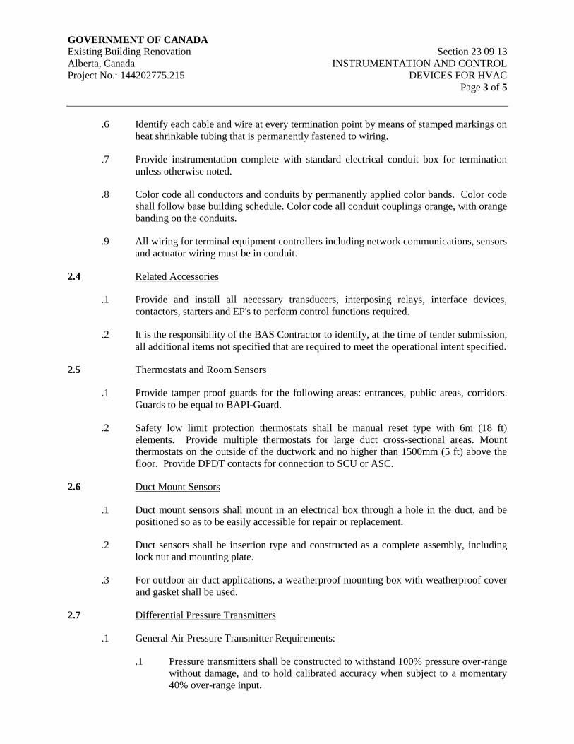
GOVERNMENT OF CANADA Existing Building Renovation Section 23 09 13
Alberta, Canada INSTRUMENTATION AND CONTROL
Project No.: 144202775.215 DEVICES FOR HVAC
Page 3 of 5
.6 Identify each cable and wire at every termination point by means of stamped markings on
heat shrinkable tubing that is permanently fastened to wiring.
.7 Provide instrumentation complete with standard electrical conduit box for termination
unless otherwise noted.
.8 Color code all conductors and conduits by permanently applied color bands. Color code
shall follow base building schedule. Color code all conduit couplings orange, with orange
banding on the conduits.
.9 All wiring for terminal equipment controllers including network communications, sensors
and actuator wiring must be in conduit.
2.4 Related Accessories
.1 Provide and install all necessary transducers, interposing relays, interface devices,
contactors, starters and EP's to perform control functions required.
.2 It is the responsibility of the BAS Contractor to identify, at the time of tender submission,
all additional items not specified that are required to meet the operational intent specified.
2.5 Thermostats and Room Sensors
.1 Provide tamper proof guards for the following areas: entrances, public areas, corridors.
Guards to be equal to BAPI-Guard.
.2 Safety low limit protection thermostats shall be manual reset type with 6m (18 ft)
elements. Provide multiple thermostats for large duct cross-sectional areas. Mount
thermostats on the outside of the ductwork and no higher than 1500mm (5 ft) above the
floor. Provide DPDT contacts for connection to SCU or ASC.
2.6 Duct Mount Sensors
.1 Duct mount sensors shall mount in an electrical box through a hole in the duct, and be
positioned so as to be easily accessible for repair or replacement.
.2 Duct sensors shall be insertion type and constructed as a complete assembly, including
lock nut and mounting plate.
.3 For outdoor air duct applications, a weatherproof mounting box with weatherproof cover
and gasket shall be used.
2.7 Differential Pressure Transmitters
.1 General Air Pressure Transmitter Requirements:
.1 Pressure transmitters shall be constructed to withstand 100% pressure over-range
without damage, and to hold calibrated accuracy when subject to a momentary
40% over-range input.
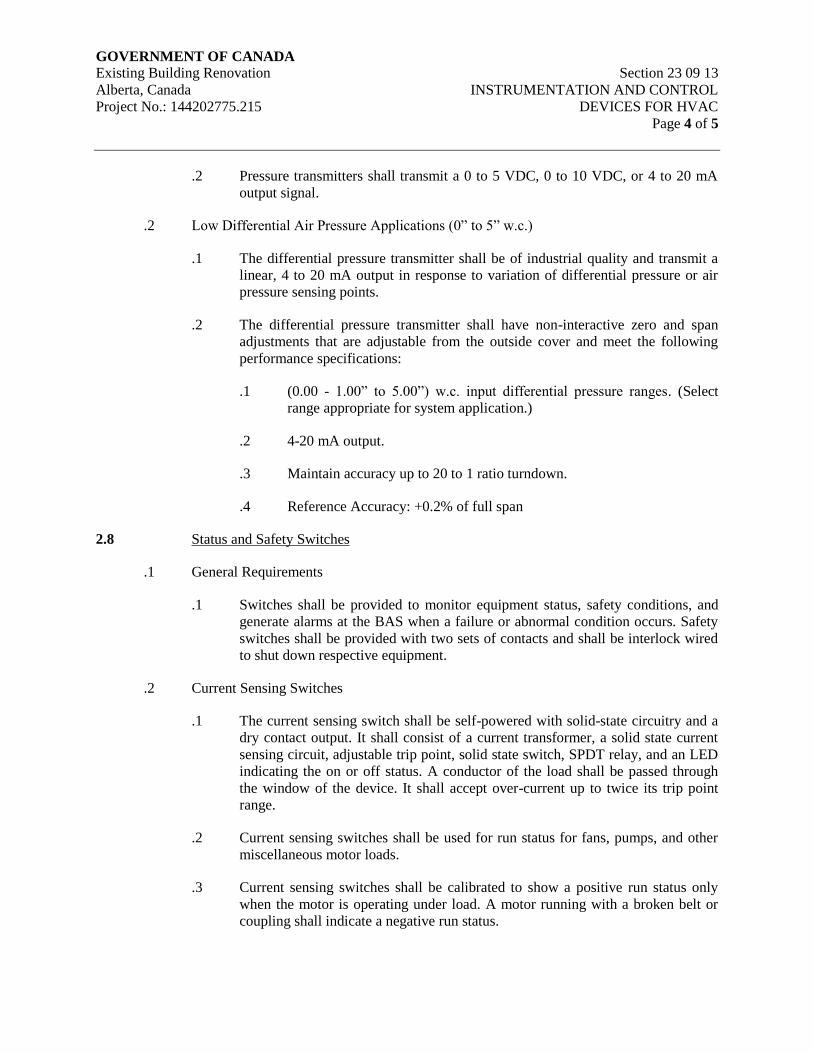
GOVERNMENT OF CANADA Existing Building Renovation Section 23 09 13
Alberta, Canada INSTRUMENTATION AND CONTROL
Project No.: 144202775.215 DEVICES FOR HVAC
Page 4 of 5
.2 Pressure transmitters shall transmit a 0 to 5 VDC, 0 to 10 VDC, or 4 to 20 mA
output signal.
.2 Low Differential Air Pressure Applications (0” to 5” w.c.)
.1 The differential pressure transmitter shall be of industrial quality and transmit a
linear, 4 to 20 mA output in response to variation of differential pressure or air
pressure sensing points.
.2 The differential pressure transmitter shall have non-interactive zero and span
adjustments that are adjustable from the outside cover and meet the following
performance specifications:
.1 (0.00 - 1.00” to 5.00”) w.c. input differential pressure ranges. (Select
range appropriate for system application.)
.2 4-20 mA output.
.3 Maintain accuracy up to 20 to 1 ratio turndown.
.4 Reference Accuracy: +0.2% of full span
2.8 Status and Safety Switches
.1 General Requirements
.1 Switches shall be provided to monitor equipment status, safety conditions, and
generate alarms at the BAS when a failure or abnormal condition occurs. Safety
switches shall be provided with two sets of contacts and shall be interlock wired
to shut down respective equipment.
.2 Current Sensing Switches
.1 The current sensing switch shall be self-powered with solid-state circuitry and a
dry contact output. It shall consist of a current transformer, a solid state current
sensing circuit, adjustable trip point, solid state switch, SPDT relay, and an LED
indicating the on or off status. A conductor of the load shall be passed through
the window of the device. It shall accept over-current up to twice its trip point
range.
.2 Current sensing switches shall be used for run status for fans, pumps, and other
miscellaneous motor loads.
.3 Current sensing switches shall be calibrated to show a positive run status only
when the motor is operating under load. A motor running with a broken belt or
coupling shall indicate a negative run status.
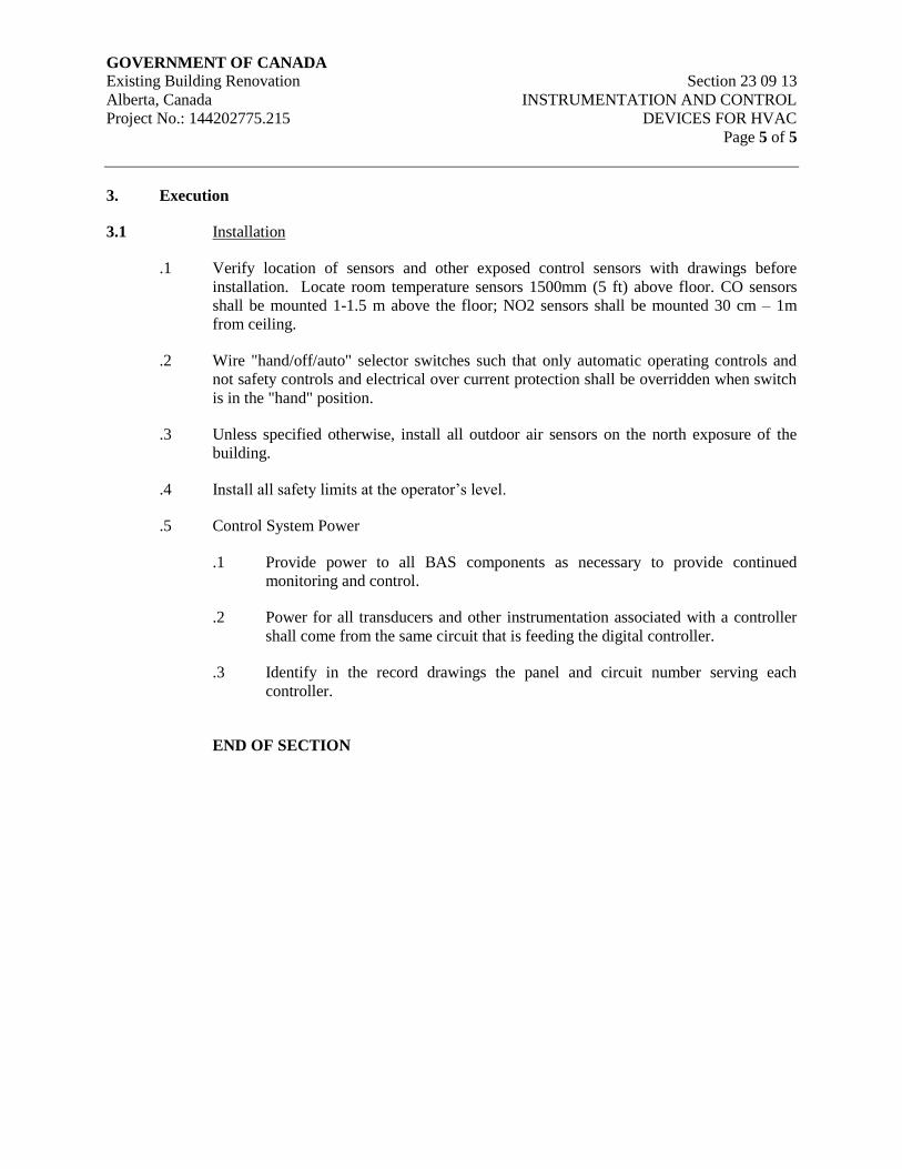
GOVERNMENT OF CANADA Existing Building Renovation Section 23 09 13
Alberta, Canada INSTRUMENTATION AND CONTROL
Project No.: 144202775.215 DEVICES FOR HVAC
Page 5 of 5
3. Execution
3.1 Installation
.1 Verify location of sensors and other exposed control sensors with drawings before
installation. Locate room temperature sensors 1500mm (5 ft) above floor. CO sensors
shall be mounted 1-1.5 m above the floor; NO2 sensors shall be mounted 30 cm – 1m
from ceiling.
.2 Wire "hand/off/auto" selector switches such that only automatic operating controls and
not safety controls and electrical over current protection shall be overridden when switch
is in the "hand" position.
.3 Unless specified otherwise, install all outdoor air sensors on the north exposure of the
building.
.4 Install all safety limits at the operator’s level.
.5 Control System Power
.1 Provide power to all BAS components as necessary to provide continued
monitoring and control.
.2 Power for all transducers and other instrumentation associated with a controller
shall come from the same circuit that is feeding the digital controller.
.3 Identify in the record drawings the panel and circuit number serving each
controller.
END OF SECTION
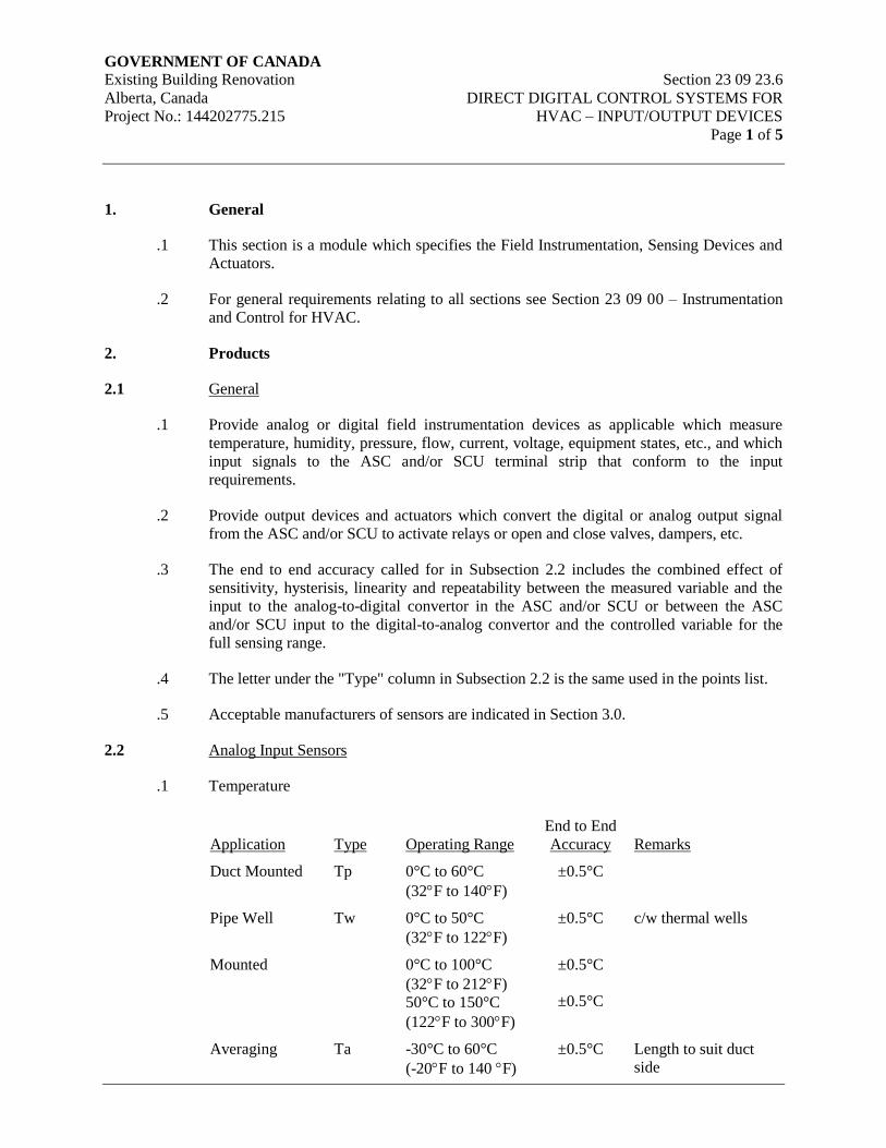
GOVERNMENT OF CANADA Existing Building Renovation Section 23 09 23.6
Alberta, Canada DIRECT DIGITAL CONTROL SYSTEMS FOR
Project No.: 144202775.215 HVAC – INPUT/OUTPUT DEVICES
Page 1 of 5
1. General
.1 This section is a module which specifies the Field Instrumentation, Sensing Devices and
Actuators.
.2 For general requirements relating to all sections see Section 23 09 00 – Instrumentation
and Control for HVAC.
2. Products
2.1 General
.1 Provide analog or digital field instrumentation devices as applicable which measure
temperature, humidity, pressure, flow, current, voltage, equipment states, etc., and which
input signals to the ASC and/or SCU terminal strip that conform to the input
requirements.
.2 Provide output devices and actuators which convert the digital or analog output signal
from the ASC and/or SCU to activate relays or open and close valves, dampers, etc.
.3 The end to end accuracy called for in Subsection 2.2 includes the combined effect of
sensitivity, hysterisis, linearity and repeatability between the measured variable and the
input to the analog-to-digital convertor in the ASC and/or SCU or between the ASC
and/or SCU input to the digital-to-analog convertor and the controlled variable for the
full sensing range.
.4 The letter under the "Type" column in Subsection 2.2 is the same used in the points list.
.5 Acceptable manufacturers of sensors are indicated in Section 3.0.
2.2 Analog Input Sensors
.1 Temperature
Application
Type
Operating Range
End to End
Accuracy
Remarks
Duct Mounted Tp 0°C to 60°C
(32F to 140F)
±0.5°C
Pipe Well Tw 0°C to 50°C
(32F to 122F)
±0.5°C c/w thermal wells
Mounted 0°C to 100°C
(32F to 212F)
50°C to 150°C
(122F to 300F)
±0.5°C
±0.5°C
Averaging Ta -30°C to 60°C
(-20F to 140 F)
±0.5°C Length to suit duct
side
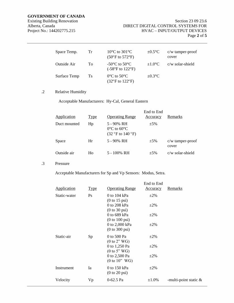
GOVERNMENT OF CANADA Existing Building Renovation Section 23 09 23.6
Alberta, Canada DIRECT DIGITAL CONTROL SYSTEMS FOR
Project No.: 144202775.215 HVAC – INPUT/OUTPUT DEVICES
Page 2 of 5
Space Temp. Tr 10°C to 301°C
(50F to 572°F)
±0.5°C c/w tamper-proof
cover
Outside Air To -50°C to 50°C
(-58°F to 122°F)
±1.0°C c/w solar-shield
Surface Temp Ts 0°C to 50°C
(32F to 122F)
±0.3°C
.2 Relative Humidity
Acceptable Manufacturers: Hy-Cal, General Eastern
Application
Type
Operating Range
End to End
Accuracy
Remarks
Duct mounted Hp 5 - 90% RH
0°C to 60°C
(32 F to 140 F)
±5%
Space Hr 5 - 90% RH ±5% c/w tamper-proof
cover
Outside air Ho 5 - 100% RH ±5% c/w solar-shield
.3 Pressure
Acceptable Manufacturers for Sp and Vp Sensors: Modus, Setra.
Application
Type
Operating Range
End to End
Accuracy
Remarks
Static-water Ps 0 to 104 kPa
(0 to 15 psi)
0 to 208 kPa
(0 to 30 psi)
0 to 689 kPa
(0 to 100 psi)
0 to 2,000 kPa
(0 to 300 psi)
±2%
±2%
±2%
±2%
Static-air Sp 0 to 500 Pa
(0 to 2” WG)
0 to 1,250 Pa
(0 to 5” WG)
0 to 2,500 Pa
(0 to 10” WG)
±2%
±2%
±2%
Instrument Ia 0 to 150 kPa
(0 to 20 psi)
±2%
Velocity Vp 0-62.5 Pa ±1.0% -multi-point static &
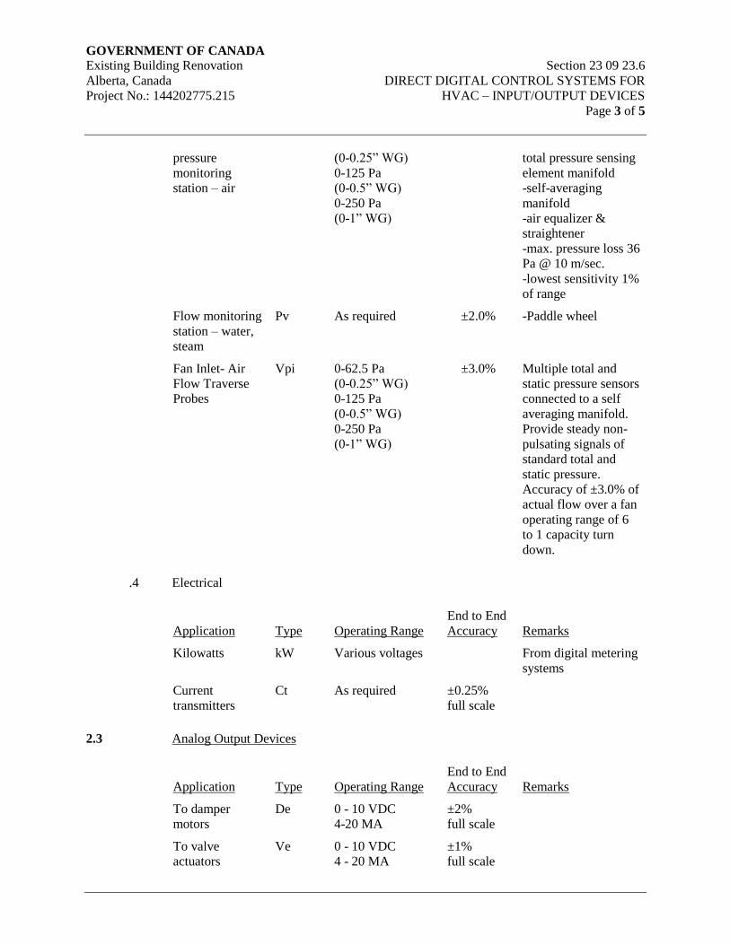
GOVERNMENT OF CANADA Existing Building Renovation Section 23 09 23.6
Alberta, Canada DIRECT DIGITAL CONTROL SYSTEMS FOR
Project No.: 144202775.215 HVAC – INPUT/OUTPUT DEVICES
Page 3 of 5
pressure
monitoring
station – air
(0-0.25” WG)
0-125 Pa
(0-0.5” WG)
0-250 Pa
(0-1” WG)
total pressure sensing
element manifold
-self-averaging
manifold
-air equalizer &
straightener
-max. pressure loss 36
Pa @ 10 m/sec.
-lowest sensitivity 1%
of range
Flow monitoring
station – water,
steam
Pv As required ±2.0% -Paddle wheel
Fan Inlet- Air
Flow Traverse
Probes
Vpi 0-62.5 Pa
(0-0.25” WG)
0-125 Pa
(0-0.5” WG)
0-250 Pa
(0-1” WG)
±3.0% Multiple total and
static pressure sensors
connected to a self
averaging manifold.
Provide steady non-
pulsating signals of
standard total and
static pressure.
Accuracy of ±3.0% of
actual flow over a fan
operating range of 6
to 1 capacity turn
down.
.4 Electrical
Application
Type
Operating Range
End to End
Accuracy
Remarks
Kilowatts kW Various voltages From digital metering
systems
Current
transmitters
Ct As required ±0.25%
full scale
2.3 Analog Output Devices
Application
Type
Operating Range
End to End
Accuracy
Remarks
To damper
motors
De 0 - 10 VDC
4-20 MA
±2%
full scale
To valve
actuators
Ve 0 - 10 VDC
4 - 20 MA
±1%
full scale
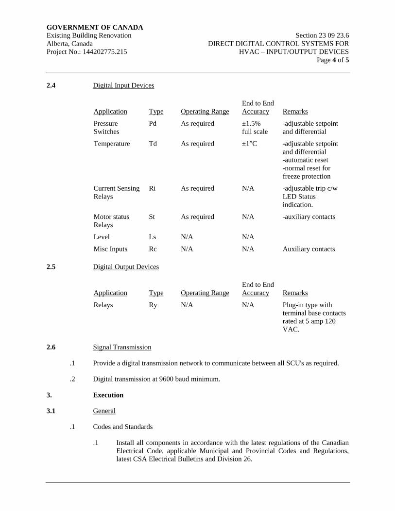
GOVERNMENT OF CANADA Existing Building Renovation Section 23 09 23.6
Alberta, Canada DIRECT DIGITAL CONTROL SYSTEMS FOR
Project No.: 144202775.215 HVAC – INPUT/OUTPUT DEVICES
Page 4 of 5
2.4 Digital Input Devices
Application
Type
Operating Range
End to End
Accuracy
Remarks
Pressure
Switches
Pd As required ±1.5%
full scale
-adjustable setpoint
and differential
Temperature Td As required ±1°C -adjustable setpoint
and differential
-automatic reset
-normal reset for
freeze protection
Current Sensing
Relays
Ri As required N/A -adjustable trip c/w
LED Status
indication.
Motor status
Relays
St As required N/A -auxiliary contacts
Level Ls N/A N/A
Misc Inputs Rc N/A N/A Auxiliary contacts
2.5 Digital Output Devices
Application
Type
Operating Range
End to End
Accuracy
Remarks
Relays Ry N/A N/A Plug-in type with
terminal base contacts
rated at 5 amp 120
VAC.
2.6 Signal Transmission
.1 Provide a digital transmission network to communicate between all SCU's as required.
.2 Digital transmission at 9600 baud minimum.
3. Execution
3.1 General
.1 Codes and Standards
.1 Install all components in accordance with the latest regulations of the Canadian
Electrical Code, applicable Municipal and Provincial Codes and Regulations,
latest CSA Electrical Bulletins and Division 26.
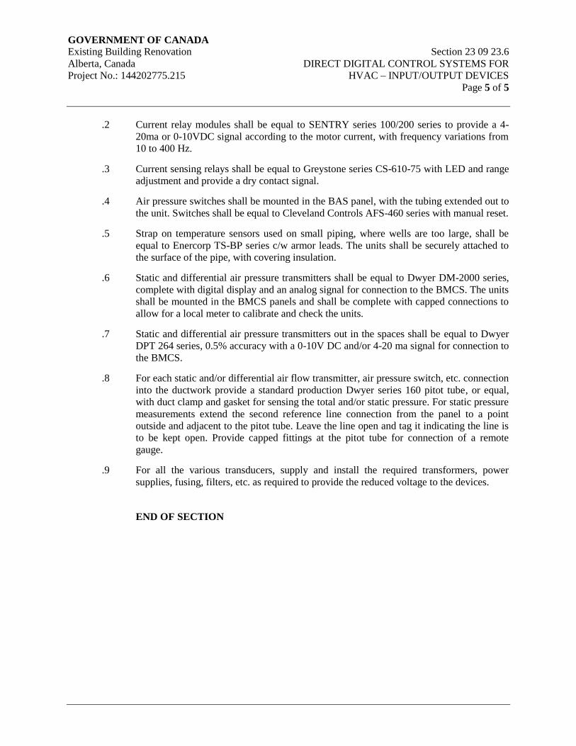
GOVERNMENT OF CANADA Existing Building Renovation Section 23 09 23.6
Alberta, Canada DIRECT DIGITAL CONTROL SYSTEMS FOR
Project No.: 144202775.215 HVAC – INPUT/OUTPUT DEVICES
Page 5 of 5
.2 Current relay modules shall be equal to SENTRY series 100/200 series to provide a 4-
20ma or 0-10VDC signal according to the motor current, with frequency variations from
10 to 400 Hz.
.3 Current sensing relays shall be equal to Greystone series CS-610-75 with LED and range
adjustment and provide a dry contact signal.
.4 Air pressure switches shall be mounted in the BAS panel, with the tubing extended out to
the unit. Switches shall be equal to Cleveland Controls AFS-460 series with manual reset.
.5 Strap on temperature sensors used on small piping, where wells are too large, shall be
equal to Enercorp TS-BP series c/w armor leads. The units shall be securely attached to
the surface of the pipe, with covering insulation.
.6 Static and differential air pressure transmitters shall be equal to Dwyer DM-2000 series,
complete with digital display and an analog signal for connection to the BMCS. The units
shall be mounted in the BMCS panels and shall be complete with capped connections to
allow for a local meter to calibrate and check the units.
.7 Static and differential air pressure transmitters out in the spaces shall be equal to Dwyer
DPT 264 series, 0.5% accuracy with a 0-10V DC and/or 4-20 ma signal for connection to
the BMCS.
.8 For each static and/or differential air flow transmitter, air pressure switch, etc. connection
into the ductwork provide a standard production Dwyer series 160 pitot tube, or equal,
with duct clamp and gasket for sensing the total and/or static pressure. For static pressure
measurements extend the second reference line connection from the panel to a point
outside and adjacent to the pitot tube. Leave the line open and tag it indicating the line is
to be kept open. Provide capped fittings at the pitot tube for connection of a remote
gauge.
.9 For all the various transducers, supply and install the required transformers, power
supplies, fusing, filters, etc. as required to provide the reduced voltage to the devices.
END OF SECTION
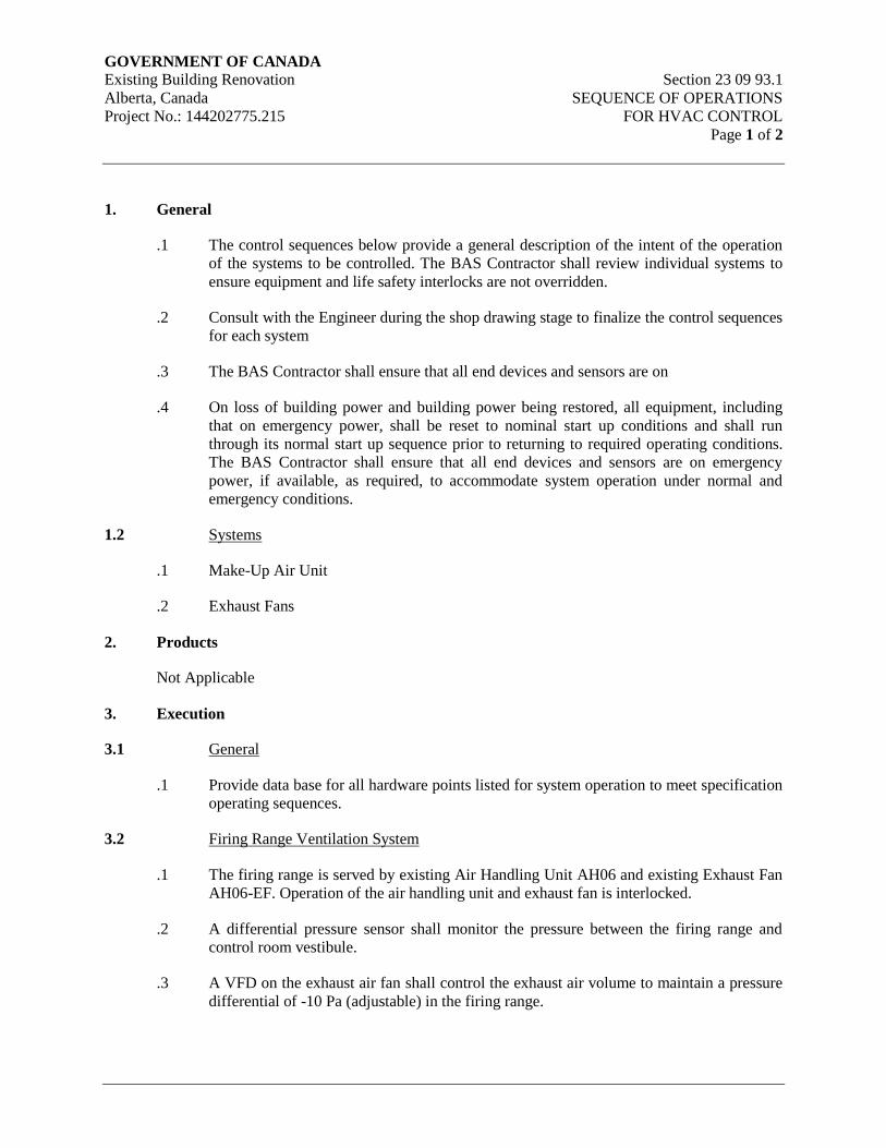
GOVERNMENT OF CANADA Existing Building Renovation Section 23 09 93.1
Alberta, Canada SEQUENCE OF OPERATIONS
Project No.: 144202775.215 FOR HVAC CONTROL
Page 1 of 2
1. General
.1 The control sequences below provide a general description of the intent of the operation
of the systems to be controlled. The BAS Contractor shall review individual systems to
ensure equipment and life safety interlocks are not overridden.
.2 Consult with the Engineer during the shop drawing stage to finalize the control sequences
for each system
.3 The BAS Contractor shall ensure that all end devices and sensors are on
.4 On loss of building power and building power being restored, all equipment, including
that on emergency power, shall be reset to nominal start up conditions and shall run
through its normal start up sequence prior to returning to required operating conditions.
The BAS Contractor shall ensure that all end devices and sensors are on emergency
power, if available, as required, to accommodate system operation under normal and
emergency conditions.
1.2 Systems
.1 Make-Up Air Unit
.2 Exhaust Fans
2. Products
Not Applicable
3. Execution
3.1 General
.1 Provide data base for all hardware points listed for system operation to meet specification
operating sequences.
3.2 Firing Range Ventilation System
.1 The firing range is served by existing Air Handling Unit AH06 and existing Exhaust Fan
AH06-EF. Operation of the air handling unit and exhaust fan is interlocked.
.2 A differential pressure sensor shall monitor the pressure between the firing range and
control room vestibule.
.3 A VFD on the exhaust air fan shall control the exhaust air volume to maintain a pressure
differential of -10 Pa (adjustable) in the firing range.
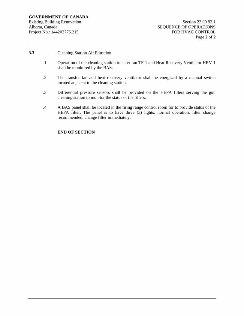
GOVERNMENT OF CANADA Existing Building Renovation Section 23 09 93.1
Alberta, Canada SEQUENCE OF OPERATIONS
Project No.: 144202775.215 FOR HVAC CONTROL
Page 2 of 2
3.3 Cleaning Station Air Filtration
.1 Operation of the cleaning station transfer fan TF-1 and Heat Recovery Ventilator HRV-1
shall be monitored by the BAS.
.2 The transfer fan and heat recovery ventilator shall be energized by a manual switch
located adjacent to the cleaning station.
.3 Differential pressure sensors shall be provided on the HEPA filters serving the gun
cleaning station to monitor the status of the filters.
.4 A BAS panel shall be located in the firing range control room for to provide status of the
HEPA filter. The panel is to have three (3) lights: normal operation, filter change
recommended, change filter immediately.
END OF SECTION
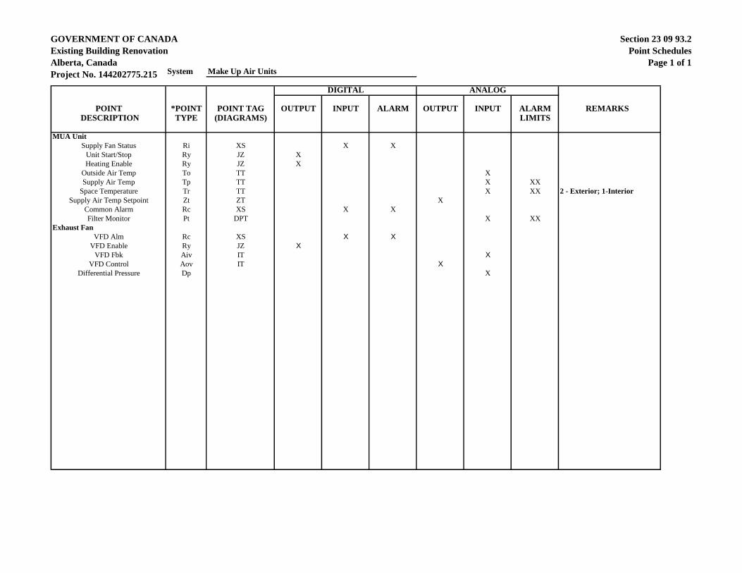
GOVERNMENT OF CANADA
Existing Building Renovation
Alberta, Canada
Project No. 144202775.215
Section 23 09 93.2
Point Schedules
Page 1 of 1 System Make Up Air Units
DIGITAL ANALOG
POINT *POINT POINT TAG OUTPUT INPUT ALARM OUTPUT INPUT ALARM REMARKS
DESCRIPTION TYPE (DIAGRAMS) LIMITS
MUA Unit
Supply Fan Status Ri XS X X
Unit Start/Stop Ry JZ X
Heating Enable Ry JZ X
Outside Air Temp To TT X
Supply Air Temp Tp TT X XX
Space Temperature Tr TT X XX 2 - Exterior; 1-Interior
Supply Air Temp Setpoint Zt ZT X
Common Alarm Rc XS X X
Filter Monitor Pt DPT X XX
Exhaust Fan
VFD Alm Rc XS X X
VFD Enable Ry JZ X
VFD Fbk Aiv IT X
VFD Control Aov IT X
Differential Pressure Dp X
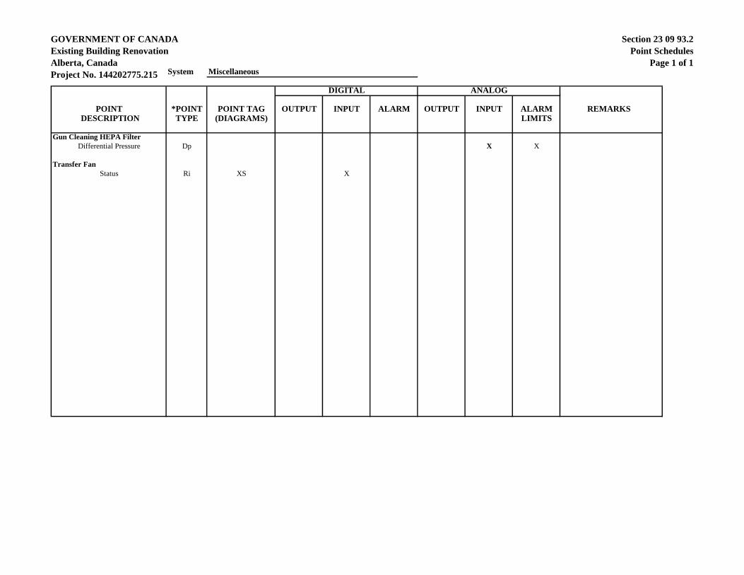
GOVERNMENT OF CANADA
Existing Building Renovation
Alberta, Canada
Project No. 144202775.215
Section 23 09 93.2
Point Schedules
Page 1 of 1 System Miscellaneous
DIGITAL ANALOG
POINT *POINT POINT TAG OUTPUT INPUT ALARM OUTPUT INPUT ALARM REMARKS
DESCRIPTION TYPE (DIAGRAMS) LIMITS
Gun Cleaning HEPA Filter
Differential Pressure Dp X X
Transfer Fan
Status Ri XS X
GOVERNMENT OF CANADA Existing Building Renovation Section 23 31 13
Alberta, Canada METAL DUCTS
Project No.: 144202775.215 Page 1 of 10
1. General
1.1 Scope
.1 Ductwork and plenums
.2 Fasteners
.3 Sealants
.4 Testing
1.2 Quality Assurance
.1 Use highest quality materials conforming to the appropriate ASTM and ANSI
specifications.
.2 The codes and standards herein referred to shall be those editions currently in effect or
accepted by the authorities in the area of jurisdiction.
.3 Be guided by “A Manual of Recommended Practice for Industrial Ventilation” issued by
the American Conference of Governmental Industrial Hygienists.
.4 Ductwork shall meet the requirements of NFPA No. 90A - Air Conditioning and
Ventilating Systems.
.5 Fabricate in accordance with SMACNA duct manuals and ASHRAE handbooks as a
minimum where more stringent requirements are not identified in the contract documents.
Straight tap fittings and dovetail joints are not permitted. Comply with SMACNA Duct
Construction Standards for duct pressure rating including requirements for cross
breaking, reinforcement, longitudinal seams, transverse joints and sealing. Confirm
pressure ratings with consultant prior to fabrication.
.6 Ductwork used on this project shall be clean and free from scale, corrosion and deposits.
All ductwork shall be degreased and wiped clean of all oil and other surface films with
appropriate solvents prior to installation.
.7 All ductwork shall be delivered clean to the site and maintained in clean condition. Dirty
ductwork shall be removed from site.
.8 Test the ductwork installation.
1.3 Definitions
.1 Low Pressure: Static pressure in duct less than 500 Pa (2” WG) and velocities less than
10 m/s (2000 fpm).
.2 Medium Pressure: Static pressure in duct less than 1500 Pa (6” WG) and velocities
greater than 10 m/s (2000 fpm).
GOVERNMENT OF CANADA Existing Building Renovation Section 23 31 13
Alberta, Canada METAL DUCTS
Project No.: 144202775.215 Page 2 of 10
.3 High Pressure: Static pressure over 1500 Pa (6” WG) and less than 2500 Pa (10” WG)
and velocities greater than 10m/s (2000 fpm).
.4 Duct sizes shown on plans are inside clear dimensions. For acoustically lined or
internally insulated ducts, maintain sizes inside ducts.
1.4 Product Options
.1 Size round ducts installed in place of rectangular ducts indicated from ASHRAE table of
equivalent round and rectangular ducts. No variation of duct configuration or sizes
permitted except by written permission of the consultant. Extent of options will be
limited for example; round duct will not be permitted on ducts downstream of terminal
units except where shown.
.2 Use of a pre-manufactured bolted transverse duct joint/seal connection is permitted on
ductwork constructed of material between 1.2mm and 0.8mm inclusive.
1.5 Reference Documents
.1 American Society of Heating, Refrigerating and Air-Conditioning Engineers, Inc.
(ASHRAE)
.2 American Society for Testing and Materials International, (ASTM)
.1 ASTM A480/A480M Standard Specification for General
Requirements for Flat-Rolled Stainless
and Heat-Resisting Steel Plate, Sheet
and Strip.
.2 ASTM A635/A635M Standard Specification for Steel, Sheet
and Strip, Heavy-Thickness Coils,
Carbon, Hot Rolled.
.3 ASTM A653/A653M Standard Specification for Steel Sheet,
Zinc Coated (Galvanized) or Zinc-Iron
Alloy Coated (Galvannealed) by the
Hot-Dip Process.
.3 Canadian Standards Association (CSA)
.1 CAN/CSA-Z317.2 Special Requirements for Heating,
Ventilation, and Air Conditioning
(HVAC) Systems in Health Care
Facilities
.4 National Fire Protection Association (NFPA)
.1 NFPA 90A Standard for the Installation of Air-
Conditioning and Ventilating Systems
.5 Sheet Metal and Air Conditioning Contractors' National Association (SMACNA)
GOVERNMENT OF CANADA Existing Building Renovation Section 23 31 13
Alberta, Canada METAL DUCTS
Project No.: 144202775.215 Page 3 of 10
.1 SMACNA HVAC Duct Construction Standards - Metal and Flexible
.2 SMACNA HVAC Air Duct Leakage Test Manual
.3 IAQ Guideline for Occupied Buildings Under Construction
.6 National Research Council (NRC)/Institute for Research in Construction
.1 National Energy Code of Canada for Buildings (NECB) 2011
.7 South Coast Air Quality Management District, California State (SCAQMD)
.1 SCAQMD Rule 1168, Adhesive and Sealant Applications
1.6 Related Work Specified in Other Sections
.1 HVAC Air Distribution System Cleaning Section 23 01 30.51
.2 Common Work Results for HVAC Section 23 05 00
.3 Hangers and Supports for HVAC Piping and Equipment Section 23 05 29
.4 Vibration and Seismic Controls for HVAC Section 23 05 48
.5 Testing, Adjusting and Balancing for HVAC Section 23 05 93
.6 HVAC Insulation Section 23 07 00
.7 Air Duct Accessories Section 23 33 00
.8 Air Outlets and Inlets Section 23 37 00
1.7 Delivery & Storage
.1 Deliver and store materials in accordance with Section 23 05 00 – Common Work
Results for HVAC.
1.8 Waste Management and Disposal
.1 Separate waste materials for reuse and recycling in accordance with Section 23 05 00 –
Common Work Results for HVAC.
2. Products
2.1 Materials
.1 Make round, oval and rectangular ductwork unless specifically noted otherwise of lock-
form quality galvanized steel, ASTM designation A93-59T, with copper bearing base
metal having 0.20% copper added and 380 g/m² class zinc coating to ASTM A525-M87.
Galvanizing quality must allow sheets to be bent flat upon themselves with no fracture to
the coating or base metal.
.2 Flexible Duct Liner: line with specified thickness of black matte faced insulation,
Manson Akousti-Liner. N.R.C. for 25mm material: minimum of 0.75 absolute
GOVERNMENT OF CANADA Existing Building Renovation Section 23 31 13
Alberta, Canada METAL DUCTS
Project No.: 144202775.215 Page 4 of 10
roughness not greater than 0.0008 feet, substrate must not be dark in colour. Seal edges
and joints with an approved fire resistant mastic. Protect leading and trailing edges with
sheet metal edging.
.3 Rigid Duct Liner: Manson Akousti-Liner-R, N.R.C. for 25mm material of 0.80. Rigid
liner to be used in plenums and/or where maximum air velocities do not exceed 24.5
m/sec.
.4 Duct Liner Protection, High Velocity: perforated galvanized steel meeting ASTM A-
527-67. Minimum thickness, ducts, 0.70mm thick to 1200mm duct diameter, 1.0mm
over 1200mm fittings 1.0mm thick all sizes.
.5 Fasteners: Use rivets and bolts throughout, sheet metal screws accepted on low pressure
ducts. Fasteners to be corrosion resistant. Kitchen exhaust ducts to be welded.
.6 Sealants: water based, fire resistive, compatible with mating materials, ULC labeled, MP
multi-purpose high velocity sealant.
.7 Strap Hangers: galvanized steel as ductwork but one (1) gauge heavier.
.8 Hangers: black steel threaded rod.
.9 Traverse Supports and Reinforcing: galvanized steel as ductwork or mild steel sections.
.10 Use aluminum ducts for swimming pool ventilation or handling moisture laden air.
2.2 Ductwork Pressures
.1 Provide ductwork and plenums fabricated from galvanized steel for the static pressure
categories listed below.
.1 1500 Pa (6" W.G.) static pressure:
.2 1000 Pa (4" W.G.) static pressure:
.1 All supply air ductwork downstream from supply air handling units
discharge, to the upstream side of mixing boxes/air valves.
.2 All exhaust and return air ductwork downstream from return/exhaust air
valves to the return/exhaust fans and downstream from the return/exhaust
fans to the air handling units and/or outdoor relief.
.3 500 Pa (2" W.G.) static pressure
.1 All supply ductwork downstream from mixing boxes/air valves to
terminal air outlets.
.2 All supply ductwork on systems without mixing boxes/air valves.
.3 All return air ductwork and plenums, except where otherwise specified.
GOVERNMENT OF CANADA Existing Building Renovation Section 23 31 13
Alberta, Canada METAL DUCTS
Project No.: 144202775.215 Page 5 of 10
.4 All exhaust and relief air ductwork and plenums, except where otherwise
specified (welding/sawdust exhaust).
.5 All outdoor air ductwork, except as otherwise specified.
2.3 Fabrication – Ductwork
.1 Complete metal ducts within themselves with no single partition between ducts. Where
width of duct exceeds 450mm (18”) cross break for rigidity. Open corners are not
acceptable.
.2 Lap metal ducts in direction of air flow. Hammer down edges and slips to leave smooth
duct interior.
.3 Construct tees, bends and elbows with radius of not less than 1½ times width of duct on
centre line.
.4 Increase duct sizes gradually not exceeding 15° divergence wherever possible.
Maximum divergence upstream of equipment to be 30° and 45° convergence
downstream.
.5 Rigidly construct metal ducts with joints mechanically tight, substantially air-tight,
braced and stiffened so as not to breathe, rattle, vibrate or sag. Caulk duct joints and
connections with sealant as ducts are being assembled.
.6 Provide easements where low pressure ductwork conflicts with piping and structure
where easements exceed 10% duct area, split into two (2) ducts maintaining original duct
area.
2.4 Lined Ductwork
.1 Comply with SMACNA “Duct Liner Application Standard”.
.2 Unless otherwise indicated, maintain the net free area of the duct dimensions given on the
drawings. Increase metal duct dimensions as necessary to compensate for the addition of
the liner.
.3 Unless otherwise indicated, lining thickness is 25mm (1”).
.4 Where round ductwork is indicated to be acoustically insulated, it shall consist of two
concentric round ducts with 25 mm (1") thick flexible fibrous glass duct liner between
the two ducts. The inner duct shall be perforated and correspond to the duct diameter
noted on the drawings. The outer duct shall be suitable for the static pressure and shall be
sealed airtight where it joins the adjacent ductwork.
.5 Provide duct lining where indicated on drawings.
2.5 Duct Sealing
.1 All supply, return and exhaust duct joints, longitudinal as well as transverse, shall be
sealed using,
GOVERNMENT OF CANADA Existing Building Renovation Section 23 31 13
Alberta, Canada METAL DUCTS
Project No.: 144202775.215 Page 6 of 10
.1 Low Pressure Ductwork:
.1 Slip Joints: Apply heavy brush-on high pressure duct sealant. Apply
second application after the first application has completely dried out.
Where metal clearance exceeds 1.5mm (16 gauge) use heavy mastic type
sealant.
.2 Flanged Joints: Soft elastomer butyl or extruded form of sealant between
flanges followed by an application of heavy brush-on high pressure duct
sealant.
.3 Other Joints: Heavy mastic type sealant.
.2 Medium and High Pressure Ductwork: Combination of woven fabrics and
sealing compound followed by an application of high pressure duct sealant.
.2 All ducts to be sealed to SMACNA Sealing Class A.
.3 Duct tapes as sealing method are not permitted.
.4 Surfaces to receive sealant should be free from oil, dust, dirt, moisture, rust and other
substances that inhibit or prevent bonding.
.5 Prior to sealing all ductwork, demonstrate sealing of a section of each type of duct and
obtain approval from the engineer.
.6 Do not insulate any section of the ductwork until it has been inspected and approved of
duct sealant application.
2.6 Turning Vanes
.1 Turning vanes shall be single wall type. Vanes in galvanized sheet metal ducts shall be
constructed from galvanized steel, minimum thickness 0.76mm (22 ga). Vanes shall be
spaced at 40mm (1-1/2") centers and shall turn through 90 deg., with a radius of 50mm
(2"). Vanes shall not include a straight trailing edge. Refer to Figs. 2-3 and 2-4 of the
SMACNA Duct Standards. Vanes and runners in aluminum ducts shall be constructed
from aluminum. Aluminum vanes shall be 0.86mm thick (18 ga).
.2 For 500 Pa (2" WC) pressure systems, install tie rods to limit the maximum unsupported
vane length to 914mm (36"). Refer to Fig. 2-4 of the SMACNA Duct Standards.
.3 For 750 Pa (3" WC) and greater pressure systems, install tie rods to limit the maximum
unsupported vane length to 460 mm (18"). Refer to 2-4 of the SMACNA Duct
Standards.
.4 When turning vanes are located in acoustically insulated ductwork, provide turning vanes
of perforated metal type with fiberglass inside.

GOVERNMENT OF CANADA Existing Building Renovation Section 23 31 13
Alberta, Canada METAL DUCTS
Project No.: 144202775.215 Page 7 of 10
3. Execution
3.1 General
.1 The project drawings are diagrammatic and although efforts have been made to provide
information regarding the number of offsets and transitions, not all are necessarily shown.
Changes may be required in duct routings, elevation and duct shape to eliminate
interference with structure and other services. All required adjustments shall be
established when coordinating and field measuring the work prior to fabrication and must
be provided as part of the contract and all associated costs must be considered and
included.
.2 Locate ducts with sufficient space around equipment to allow normal operating and
maintenance activities.
.3 Prior to the fabrication of ductwork, co-ordinate and field measure all ductwork to ensure
a complete installation respecting all other services. Fabricate ductwork from field
measurements and not from plans and shop drawings exclusively. Failure to do so will
not constitute an extra to the Contract.
.4 Provide all necessary fittings, offsets, and alternate construction methods to facilitate the
installation.
.5 Proper sized openings shall be arranged for in the correct locations through all slabs and
walls. Openings shall be planned to include for the installation of fire dampers at all
rated fire separations.
.6 Where ducts penetrate roofs, install sleeves and roof curb c/w flashing and
counterflashing. Pack sleeves in roof with fibreglass insulation.
.7 During construction, protect openings in ductwork, from dust infiltration, by covering
with polyethylene, and protect floor outlet duct openings with metal caps. Clean any
ductwork found to be dirty at no extra cost to the Contract.
.8 Where ductwork is required to pass through open web steel joists, coordinate with the
joist fabricator before fabricating ductwork.
.9 Where a duct contains a fire or smoke damper, construct the duct so that the free area of
the duct is maintained through the fire or smoke damper.
.10 Where a duct is to be internally insulated, enlarge the duct so as not to reduce the duct
free area.
3.2 Installation
.1 Make the taper of diverging transitions less than 20 deg. and the taper of converging
transitions less than 30 deg., in accordance with Fig. 2-9 of the SMACNA Duct
Standards. Maximum divergence upstream of equipment to be 30 deg. and 45 deg.
convergence downstream.
GOVERNMENT OF CANADA Existing Building Renovation Section 23 31 13
Alberta, Canada METAL DUCTS
Project No.: 144202775.215 Page 8 of 10
.2 Make the inside radius of any rectangular duct elbow at least equal to the duct width,
measured in the direction of the radius. If space conditions do not permit a full radius
elbow to be installed, use square elbows with multi-blade turning vanes.
.3 Install duct necks before grilles, registers and diffusers and cushion heads after diffuser
take-offs as required to suit site conditions and maximize acoustic performance of the
ductwork.
.4 Where indicated, install adjustable air turning devices, where full radius take-off fittings
cannot be installed, in accordance with Fig. 2-16 of the SMACNA Duct Standards.
Adjustment shall be accessible outside the duct with lockable quadrant operator or
through the grille or register with key-operated worm gear mechanism.
.5 Cross-break or bead all metal duct panels unless otherwise noted.
.6 Do not cross-break duct panels on 750 Pa (3" WC) and greater static pressure systems.
.7 Do not cross-break bottom duct panels when ductwork is handling moisture.
.8 Roof mounted ducts shall have standing seams and shall be sealed weather tight.
.9 Provide moisture collection sections inside all louvres for outside air and exhaust air.
.10 Support ductwork using galvanized steel straps, cadmium plated threaded rods, flat bar or
angle hangers. Attachments to the structure shall be compatible with the structure and
selected for the load of the ductwork. Refer to Section 23 05 29 – Hangers, Supports,
Access Doors for HVAC Piping and Equipment.
.11 Support duct risers at their base and at each floor and at not greater than 3.7 m (12 ft)
intervals.
.12 Ducts passing through non-rated fire separations, sound insulated walls and through non-
rated walls and floors shall be tightly fitted and sealed on both sides of the separation
with silicon sealant to prevent passage of smoke and/or transmission of sound. (U.L.C.
approved fire stop sealant is not a requirement). Where ducts are insulated provide a
0.61mm (24 ga) thick galvanized steel band tightly fitted around insulation and then
caulk to band.
.13 Provide drip pans under piping and shields for protection of electrical panels and
equipment.
.14 Complete metal ducts within themselves with no single partition between ducts. Where
width of duct exceeds 450mm (18”) crossbrace for rigidity. Open corners are not
acceptable.
.15 Construct tees, bends and elbows with radius of not less than 1-1/2 times width of duct on
centre line. Where not possible and where rectangular elbows are specified, provide
turning vanes. Where acoustical lining is provided, provide turning vanes of perforated
metal type with fiberglass inside.
GOVERNMENT OF CANADA Existing Building Renovation Section 23 31 13
Alberta, Canada METAL DUCTS
Project No.: 144202775.215 Page 9 of 10
.16 Coordinate the location of duct access doors.
.17 Arrange access doors so that they open against the airflow and static pressure.
.18 Provide openings in ductwork where required to accommodate thermometers and
controllers. Provide pitot tube openings where required for testing of systems, complete
with metal cap with spring device or screw to ensure against air leakage. Where
openings are provided in insulated ductwork, install insulation material inside a metal
ring.
.19 Interrupt duct linings at fire, balancing, backdraft and smoke dampers so as not to
interfere with operation of devices. Provide sheet metal edge protection over linings on
both side of damper device.
.20 Protect carbon steel ductwork exposed to weather by painting or coating with suitable
weather resistant material.
.21 Install ducts associated with fans subject to forced vibration with flexible connections
immediately adjacent to equipment. Refer to Section 23 33 13 – Air Duct Accessories.
.22 Do not use flexible duct to change direction. Provide a minimum of three (3) duct
diameters of straight metal duct between box inlet and flexible connector.
.23 Connect diffusers boots to low pressure ducts with 300mm (12”) maximum stretched
length of flexible duct. Hold in place with caulking compound and strap or clamp.
.24 Prove that ductwork is substantially air tight before covering or concealing.
.25 All segmented type elbows shall be spot welded. No adjustable type elbows are allowed.
3.3 Ductwork Tests
.1 Refer to Section 23 05 00 – Common Work Results for system testing and startup
requirements.
.2 All ductwork, regardless of service shall be subjected to pressure tests with costs borne
under the mechanical construction contract. All duct sections are to be tested except as
approved by the consultant.
.3 Equivalency of duct quality testing may be granted to the contractor on the following
basis, at the consultant’s discretion:
.1 The contractor submits to the consultant and obtains approval of a quality control
process for ductwork testing.
.2 For each duct system (low and high pressure) test one main length for each of,
supply, return and/or exhaust air for establishment of base-line quality.
.3 If defects are recorded, or if any duct section fails the test procedure established,
which, in the opinion of the consultant, are serious, the consultant may request
further duct testing to a maximum of 100% of all ductwork joints at his
GOVERNMENT OF CANADA Existing Building Renovation Section 23 31 13
Alberta, Canada METAL DUCTS
Project No.: 144202775.215 Page 10 of 10
discretion. The contractor shall bear all related costs of the extra testing
procedures as an acknowledgement of maintenance of project quality
requirements.
.4 High and medium pressure duct. Test in sections of no more than complete floors. Test
to a static pressure of 1½ times the actual working pressure, but no less than 2.0 kPa (8”
WG) Maximum leakage shall be no more than ½% of the flow in the section tested,
without audible leaks. Test and seal leaks before any ductwork is concealed or covered.
.5 All low pressure ductwork, leak test at 1½ times the actual working pressure, but no less
than 750 Pa (3” WG). Leakage shall be inaudible and not detectable by feel and not to
exceed 5% of the flow in the section tested.
.6 Test equipment shall be supplied for these tests and must be presented for approval of a
consultant before use.
.7 Pressure test kit shall consist of a high pressure blower discharging through a tapered
nozzle into an 800mm x 75mm (32”x3”) diameter test section. The test section shall be
complete with diffuser plate and 22.2mm diameter orifice plate with static pressure
connections on each side of the orifice. A U-tube manometer shall be used to measure
pressure drop across the orifice in inches water gauge.
.8 Test procedure shall be as follows:
.1 Close off open end of all take-offs (except one) with suitable plugs or cap;
.2 Attach pressure kit to open take-off;
.3 Rise duct static pressure and hold by adjusting blower inlet area;
.4 Measure leakage by manometer reading across orifice plate, reading shall not
exceed 0.25 kPa (1” WG).
END OF SECTION
GOVERNMENT OF CANADA Existing Building Renovation Section 23 33 00
Alberta, Canada AIR DUCT ACCESSORIES
Project No.: 144202775.215 Page 1 of 8
1. General
1.1 Scope
.1 Access doors (duct and plenum access)
.2 Fire dampers
.3 Balancing dampers
.4 Flexible connections
.5 Backdraft dampers
.6 Turning vanes
.7 Sealants
1.2 Quality Assurance
.1 Fire dampers shall be ULC listed and constructed in accordance with ULC Standard S112
"Fire Dampers".
.2 Fusible links on fire dampers shall be constructed to ULC Standard S505.
.3 Demonstrate re-setting of fire dampers to authorities having jurisdiction and Owner's
representative.
.4 Access doors shall be ULC labelled.
.5 Accessories shall meet the requirements of NFPA 90A, Air Conditioning and Ventilating
Systems. Fabricate in accordance with ASHRAE Handbooks and SMACNA Duct
Manuals.
.6 Flexible air duct shall comply with NFPA 90A and UL181 Standard for Factory-Made
Air Ducts and Air Connectors.
.7 At job completion, demonstrate that all fire dampers operate freely and without binding,
and that ratings of fire dampers meet or exceed the rating of the fire wall.
1.3 Reference Standards
.1 American National Standards Institute/National Fire Protection Association
(ANSI/NFPA)
.1 ANSI/NFPA 90A Installation of Air Conditioning and
Ventilating Systems.
.2 American Society for Testing and Materials (ASTM)
GOVERNMENT OF CANADA Existing Building Renovation Section 23 33 00
Alberta, Canada AIR DUCT ACCESSORIES
Project No.: 144202775.215 Page 2 of 8
.1 ASTM A 653M Standard Specification for Steel Sheet,
Zinc-Coated (Galvanized) or Zinc-Iron
Alloy-Coated (Galvannealed) by
Hot-Dip Process
.3 Sheet Metal and Air Conditioning Contractors' National Association (SMACNA)
.1 SMACNA - HVAC Duct Construction Standards - Metal and Flexible
.4 Underwriters Laboratories of Canada (ULC)
.1 CAN4-S112 Fire Test of Fire Damper Assemblies.
.2 CAN4-S112.2 Fire Test of Ceiling Firestop Flap
Assemblies.
.3 ULC-S505 Fusible Links for Fire Protection
Service.
1.4 Related Work Specified in Other Sections
.1 Common Work Results for HVAC Section 23 05 00
.2 Metal Ducts Section 23 31 13
.3 Air Outlets and Inlets Section 23 37 00
1.5 Delivery & Storage
.1 Deliver and store materials in accordance with Section 23 05 00 – Common Work
Results for HVAC.
1.6 Waste Management and Disposal
.1 Separate waste materials for reuse and recycling in accordance with Section 23 05 00 –
Common Work Results for HVAC.
1.7 Submittals
.1 Submit shop drawings for review.
2. Products
2.1 Acceptable Manufacturers
1. Access Doors : Controlled Air, Nailor, Air-O-Metal, Titus
2. Backdraft Dampers : EH Price, Greenheck, NCA, Ruskin, Nailor
3. Balancing Dampers : EH Price, Greenheck, NCA, Ruskin, Nailor
4. Duct Hardware : Ventlock, Duro-Dyne, Brytex
GOVERNMENT OF CANADA Existing Building Renovation Section 23 33 00
Alberta, Canada AIR DUCT ACCESSORIES
Project No.: 144202775.215 Page 3 of 8
5. Fire Dampers : EH Price, Greenheck, NCA, Ruskin, Nailor
6. Sealants : Ductmate
2.2 Duct Access Doors
.1 Square/Rectangular Doors: Frame shall be die-formed of 0.85mm (22 gauge) galvanized
steel complete with notched knock-over tabs for installation. Door shall be die-formed
0.85mm (22 gauge) galvanized steel and be of double skin construction with 25mm (1”)
of insulation fully enclosed within. A positive seal, polyethylene gasket shall be secured
to each door for low leakage. Door shall meet SMACNA requirements for systems up to
500 Pa (2” wc) and be hinged on one side with camlock closure. Standard of acceptance:
Nailor Series 08S.
.2 Flat Oval Doors: Frame shall be of oval design, die-formed of minimum 0.70mm (24
gauge) galvanized steel with 5mm (3/16”) pre-punched mounting holes. Door shall be
die-formed of minimum 0.70mm (24 gauge) galvanized steel and be of double skin
construction with 25mm (1”) of insulation fully enclosed within. Door shall be complete
with safety handle on sizes 200mm x 125mm 8”x5”) thru 460mm x 250mm (18”x10”),
two safety handles on larger sizes. Door shall be secured with plated steel wing nut
fasteners, with bulb type seal integrally fastened to door for positive seal. Standard of
acceptance: Nailor Series 0800-5.
2.3 Plenum Access Doors
.1 600 mm x 1200 mm in air plenums to accommodate total body access to mechanical
components.
2.4 Fire Dampers
.1 Fire dampers shall be ULC listed and labelled. Fire damper assemblies to be fire tested in
accordance with CAN4-S112.
.2 Fabricate of galvanized steel or prime coated black steel weighted for static application
(i.e., non-ducted) and spring operated for dynamic application (i.e., ducted), to close and
lock in closed position when released by fusible link.
.3 Fire dampers shall be curtain type static weighted for non-ducted systems and dynamic
spring operated for ducted systems with damper blades retained out of air stream in a
recess so free area of connecting ductwork is not reduced.
.4 Fusible links shall be set for 73.9°C (165F).
.5 Fire dampers shall be curtain type with damper blades retained out of air stream in a
recess (Type B) so free area of connecting ductwork is not reduced, unless noted
otherwise on the drawings.
.6 Refer to architectural drawings for ratings of fire walls and provide fire dampers with
compatible ratings.
GOVERNMENT OF CANADA Existing Building Renovation Section 23 33 00
Alberta, Canada AIR DUCT ACCESSORIES
Project No.: 144202775.215 Page 4 of 8
2.5 Fire Stop Flaps
.1 Fire stop flabs to be ULC listed and labelled and fire tested in accordance with
CAN4-S112.2.
.2 Fabricate of heat retardant fabric in galvanized or prime coated black steel frame, spring
loaded action to close and lock in closed position when released by fusible link.
.3 Blanket shall be retained in a recess so free area of connecting ductwork is not reduced.
.4 Flaps shall be held open with fusible link conforming to ULC-S505. Fusible links shall
be set for 73.9°C (165°F).
2.6 Splitter Dampers
.1 Fabricate splitter dampers of double thickness sheet metal to streamline shape, properly
stiffened to avoid vibration.
.2 Fabricate galvanized steel, minimum 1.6mm (16 gauge), and provide with adjustable rod
and locking screw.
.3 On externally insulated ductwork, install operating mechanisms on a steel bridge type
mounting base to permit continuity of insulation under the mechanism.
2.7 Balancing Dampers
.1 Fabricate of galvanized steel, minimum 1.6mm (16 gauge). Full blade-length shafts of
hollow square construction with blades rigidly fastened along entire blade length.
.2 Lockable quadrant type operating mechanism with end bearings on accessible rectangular
ducts up to 400mm (16”) deep and on accessible round ducts.
.3 Wide pitch screw operating mechanism with crank operator and end bearings on
accessible rectangular ducts 425mm (17”) and over in depth and on all inaccessible
rectangular and round ducts.
.4 On rectangular ducts up to 275mm (11”) deep construct of single blade (butterfly) type.
.5 On rectangular ducts 300mm to 400mm (12” x 16”) deep construct of two opposed
blades mechanically interlocked with pivots at quarter points.
.6 On rectangular ducts over 425mm (17”) deep construct of multiple opposed blades,
mechanically interlocked with blades no greater than 200mm (8”) deep and pivots
equally spaced.
.7 On round ducts construct of single blade (butterfly) type. On 500 Pa (2” WG) class and
on all dampers over 300mm (12”) diameter fabricate with full blade-length shaft.
.8 Construct damper blades for medium and high pressure systems to block air passage 70%
maximum. Provide complete with locking type handles.
GOVERNMENT OF CANADA Existing Building Renovation Section 23 33 00
Alberta, Canada AIR DUCT ACCESSORIES
Project No.: 144202775.215 Page 5 of 8
.9 Provide over-ride limiting stops on all operating mechanisms.
.10 Identify the air flow direction and blade rotation and open and close positions on
operating mechanism.
.11 On round ductwork, install operating mechanism on a steel mounted base firmly secured
to the ductwork.
.12 On externally insulated ductwork, install operating mechanisms on a steel bridge type
mounting base to permit continuity of insulation under the mechanism.
2.8 Flexible Connections
.1 Fabricate of ULC approved neoprene coated flameproof glass fabric approximately
0.51mm (0.02”) thick, 150mm (6”) wide tightly crimped into metal edging strip and
attached to ducting and equipment by screws or bolts at 150mm (6”) intervals. Flexible
connection airtight at 500Pa (2” WG).
2.9 Backdraft Dampers
.1 Dampers shall be suitable for maximum 7.6m/s (1500 fpm) spot velocities and up to
996 Pa (4” wc) back pressure..
.1 Frame shall be constructed of extruded aluminum with a 2.29mm (0.09”)
minimum wall thickness with 2.75mm (12 gauge) galvanized steel structural
braces at each corner.
.2 Blades shall be 0.64mm (0.025”) minimum roll formed aluminum with extruded
vinyl blade edge seals mechanically locked into blade edge. Blades shall include
field adjustable, zinc plated steel counter balance weights to allow pressure relief
at less than 2.5 Pa (0.01” wc).
.3 Bearings shall be corrosive resistant, long life synthetic type for quiet operation.
.4 Linkage shall be 12mm (½”) wide tiebar concealed in frame.
.2 Dampers shall be suitable for maximum 17.8 m/s (3500 fpm) spot velocities and
minimum 996 Pa (4” wc) back pressure.
.1 Frame shall be constructed of extruded aluminum with a 3.2mm (0.125”)
minimum wall thickness with 2.75mm (12 gauge) galvanized steel structural
braces at each corner.
.2 Blades shall be 1.8mm (0.07”), minimum wall thickness, extruded aluminum
with extruded vinyl blade edge seals mechanically locked into blade edge.
Blades shall include field adjustable, zinc plated steel counter balance weights.
.3 Bearings shall be corrosive resistant, long life synthetic type for quiet operation.
.4 Linkage shall be 12mm (½”) wide tiebar connected to stainless steel pivot pins.
GOVERNMENT OF CANADA Existing Building Renovation Section 23 33 00
Alberta, Canada AIR DUCT ACCESSORIES
Project No.: 144202775.215 Page 6 of 8
2.10 Test Holes
.1 DuroDyne IP series, complete with extenders for insulation thickness, flat gaskets for
rectangular ductwork and molded rubber gaskets for round ductwork. Cut holes with
hole saw and deburr edges. Install test holes with rivets or bolts with head on the interior
of the ductwork.
2.11 Turning Vanes
.1 Full radius arc; single blade vanes.
.2 Acoustic vanes constructed in airfoil pattern with fibrous glass padding, 0.8 mm
perforated lining.
2.12 Sealants
.1 Comply with South Coast Air Quality Management District (SCAQMD) Rule #1168.
.2 Sealants to contain zero VOC and comply with LEED cr4.1 – Requirements for Low
Emitting Materials.
3. Execution
3.1 Duct Access Doors
.1 Provide access door minimum 450mm x 350mm or 50mm (18”x14” or 2”) smaller than
duct dimension for cleaning and inspection at positions indicated by drawings and as
follows:
.1 At 6.0m (20’-0”) intervals on all horizontal ducts.
.2 At 12.0m (40’-0”) intervals in all vertical duct systems.
.3 At the base of all duct risers.
.4 Both sides of turning vanes in all ducts.
.5 At each fire damper location.
.6 At each side of all heating or cooling coils.
.7 At all locations of internally duct mounted devices including automatic dampers,
damper motors, duct mounted smoke detectors and heat detectors, and control
sensors and devices.
3.2 Plenum Access Doors
.1 Install plenum access doors where required to service mixing dampers, coils, filters,
humidifiers and fans. Install 150mm (6”) above floor. Arrange door swing so that fan
static holds door in closed position.

GOVERNMENT OF CANADA Existing Building Renovation Section 23 33 00
Alberta, Canada AIR DUCT ACCESSORIES
Project No.: 144202775.215 Page 7 of 8
3.3 Fire Dampers
.1 Install to manufacturer’s instructions and recommendations and to the satisfaction of the
authorities having jurisdiction.
.2 Provide fire dampers at locations shown, where ducts and outlets pass through fire rated
components, and where required by authorities having jurisdiction. Install to NFPA 90A
and SMACNA Standard “Fire Damper Guide for Air Handling Systems”. Refer to
drawings for locations.
.3 Fire dampers shall be complete with required perimeter mounting angles, sleeves,
breakaway duct connections, corrosion resistant springs, bearings, bushings and hinges.
.4 Coordinate with the General Contractor for correct size openings and proper fire guard
sleeving for fire damper penetration.
.5 At each point where ducts pass through partitions, the opening around the duct shall be
sealed with non-combustible material.
.6 Ensure openings through gypsum wall-board partitions are protected in accordance with
local regulations and ULC Information Bulletin No. 80-2. Maximum fire damper size
through gypsum wall-board partitions shall be 1200mm wide x 1500mm high (48”x60”).
.7 All fire dampers and fire stop flaps are to be left in the closed position for balancing
contractor to fix open.
.8 Support ceiling fire stops from the structure above the fire stop and not from air outlets
on associated ductwork.
.9 Recess curtain type fire damper so that free area of connecting ductwork is not reduced.
.10 Provide curtain type fire dampers in duct systems with pressure greater than 250 Pa (1”
WC).
.11 Provide multi-blade, offset butterfly or recessed curtain blade fire dampers on duct
systems with pressure less than 250 Pa (1” WC).
3.4 Fire Stop Flaps and Thermal Blankets
.1 Install fire stop flaps on all ceiling grilles and diffusers located in rated ceiling
assemblies.
.2 Provide fire resistant thermal blanket in conjunction with fire stop flaps on ceiling
diffusers in fire rated ceiling assemblies to complete the rating from ceiling to fire stop
flap.
.3 Install to SMACNA Standard.
GOVERNMENT OF CANADA Existing Building Renovation Section 23 33 00
Alberta, Canada AIR DUCT ACCESSORIES
Project No.: 144202775.215 Page 8 of 8
3.5 Balancing Dampers
.1 Install balancing dampers on each branch of low velocity supply, return and exhaust
ducts, including run outs to room air outlets and inlets.
.2 Provide balancing dampers on medium and high pressure systems where indicated.
Splitter dampers shall not be used on medium and high pressure system.
.3 Single blade dampers permitted on rectangular ductwork up to 300mm maximum duct
height.
.4 Do not install closer than two (2) duct widths to elbows or intersections.
3.6 Flexible Connections
.1 Install ducts associated with fans and equipment subject to forced vibration with flexible
connections, immediately adjacent to equipment and/or where indicated on drawing.
Provide for 150mm (6”) spacing between ducts and equipment. Install with just
sufficient slack to prevent vibration transmission.
.2 Allow 100mm (4”) movement of medium pressure fans and 50mm (2”) movement of low
pressure fans.
.3 For connections to medium and high pressure fans, and in potentially wet locations,
install 12mm (½”) thick neoprene pad over fabric and hold in place with additional metal
straps.
.4 Provide fire retardant flexible connectors on kitchen exhaust systems.
3.7 Backdraft Dampers
.1 Provide gravity backdraft dampers on all exhaust air outlets to outdoor and exhaust fans
where motorized dampers are not indicated, and where shown on drawings.
3.8 Turning Vanes
.1 Install turning vanes in duct elbows where centerline radius is less than 1¼ times the
turning dimension of the duct.
3.9 Test Holes
.1 Provide at suitable locations on each duct main at the suction and discharge of every fan
to facilitate total and static pressure readings.
3.10 Motorized Dampers
.1 Install dampers furnished by the control trade.
.2 Ensure suitable clearance is provided for the installation and operation of the damper
operator and linkage when setting motorized dampers in place.
END OF SECTION
GOVERNMENT OF CANADA Existing Building Renovation Section 23 34 00
Alberta, Canada HVAC FANS
Project No.: 144202775.215 Page 1 of 4
1. General
1.1 Scope
.1 Centrifugal Fans
.2 Belted Vent Sets
.3 Fan Accessories
1.2 Quality Assurance
.1 All fans of any specific type on the project shall be supplied by a single manufacturer.
.2 Conform to AMCA Bulletins regarding construction and testing. Fans shall bear AMCA
certified rating seal for performance and sound ratings.
.3 Fans shall bear CSA label.
1.3 Reference Standards
.1 Air Movement and Control Association International, Inc. (AMCA)
AMCA 99 Standards Handbook .1
AMCA 300 Reverberant Room Method for Sound Testing of Fans .2
AMCA 301 Methods for Calculating Fan Sound Ratings from .3
Laboratory Test Data
.2 American National Standards Institute (ANSI) / Air Movement and Control Association
International, Inc. (AMCA)
ANSI/AMCA 210 Laboratory Methods of Testing Fans for Rating. .1
.3 American National Standards Institute (ANSI) / American Society of Heating,
Refrigeration and Air Conditioning Engineers, Inc. (ASHRAE)
ANSI/ASHRAE 51 Laboratory Methods of Testing Fans for Rating .1
.4 Canadian General Standards Board (CGSB)
CGSB 1-GP-181M Coating, Zinc Rich, Organic, Ready Mixed .1
1.4 Related Work Specified in Other Sections
.1 Common Work Results for HVAC Section 23 05 00
.2 Common Motor Requirements for HVAC Equipment Section 23 05 13

GOVERNMENT OF CANADA Existing Building Renovation Section 23 34 00
Alberta, Canada HVAC FANS
Project No.: 144202775.215 Page 2 of 4
.3 Variable Frequency Drives for HVAC Equipment Section 23 05 14
.4 Vibration and Seismic Controls for HVAC Section 23 05 48
.5 Testing, Adjusting and Balancing for HVAC Systems Section 23 05 93
.6 Metal Ducts Section 23 31 13
.7 Air Duct Accessories Section 23 33 00
1.5 Delivery & Storage
.1 Deliver and store materials in accordance with Section 23 05 00 – Common Work
Results for HVAC.
1.6 Waste Management and Disposal
.1 Separate waste materials for reuse and recycling in accordance with Section 23 05 00 –
Common Work Results for HVAC.
1.7 Job Conditions
.1 Do not operate fans for any purpose, temporary or permanent until ductwork is clean,
filters are in place and bearings are lubricated.
.2 Refer to Section 23 05 00 – Common Work Results for HVAC.
1.8 Alternates
.1 Equivalent fan selections shall not increase motor kilowatts, increase rpm, increase noise
level, increase tip speed by more than 10%, or increase inlet air velocity by more than
20%, from that of the specified fan.
1.9 Submittals
.1 Submit shop drawings that show, as a minimum, the following:
.1 Fan size and class for application,
.2 Fan performance including capacity, external static pressure and fan speed
.3 Fan curves showing fan performance with fan and system operating point plotted
on curves
.4 Dimensions
.5 Motor capacity and electrical characteristics
.6 Acoustical data
GOVERNMENT OF CANADA Existing Building Renovation Section 23 34 00
Alberta, Canada HVAC FANS
Project No.: 144202775.215 Page 3 of 4
2. Products
2.1 Acceptable Manufacturers
1. Centrifugal Fans : Trane, Chicago, Twin City, PennBarry,
Northern Blower, ACME, Greenheck,
Loren Cook, Delhi
2.2 General
.1 Statically and dynamically balance fans so no objectionable vibration or noise is
transmitted to occupied areas of the building.
.2 Provide balanced variable sheaves for motors 11.2 kW (15 HP) and under and fixed
sheave for 15 kW (20 HP) and over.
.3 Fans are to be capable of accommodating static pressure variations of ±10% with no
objectionable operating characteristics.
.4 Select and design wheel and shaft so that fan does not pass through any critical speed to
reach maximum operating speed.
.5 Unless otherwise indicated, equip fans with heavy duty grease lubricated ball or roller
bearings of self-aligning type, with ample thrust provision to prevent end play during
normal bearing life. Ensure lubricating points are readily and safely accessible after
installation.
.6 Provide guard screens for fans having exposed inlet or outlets, bolted to permit removal.
.7 Supply replacement pulleys and sheaves for fans as required to properly balance the
systems to design flows at actual job site static pressure conditions. Obtain requirements
from balancing agency.
.8 Provide cross linkage for inlet vanes on double inlet fan.
.9 Size motors for parallel operating fans for non-overloading operation with only one fan
operating.
.10 Provide belt guards with tachometer holes.
.11 External static pressure means external to the fan cabinet and all accessories such as
backdraft dampers, mixing boxes, filters and coils, etc. These accessories if supplied as
part of the unit are considered as internal losses for fan.
.12 Use ground and polished steel shafts with rust preventative coating.
.13 Finish all ferrous parts with primer and baked enamel top coat.
.14 Two speed motors shall have separate winding for each speed.
GOVERNMENT OF CANADA Existing Building Renovation Section 23 34 00
Alberta, Canada HVAC FANS
Project No.: 144202775.215 Page 4 of 4
2.3 Belted Vent Sets
.1 Comply generally with requirements of centrifugal fans suitable for pressure to1750 Pa
(7 in. WG).
.2 Provide sets complete with SWSI centrifugal fan, V-belt or direct drive as indicated, with
motor and protective enclosure for motor and drive. Protective hoods to have vents for
motor cooling and be readily removable.
.3 Provide with multi-blade rattle free backdraft damper with felt lined bladed edges as
noted on drawings.
.4 Provide belt guards with tachometer holes. Provide weatherproof housing.
.5 Provide all cabinets lined with 25mm (1”) acoustic insulation.
3. Execution
3.1 Installation
.1 Where inlet or outlet is exposed, provide safety screen.
.2 Provide belt guards on belt driven fans complete with tachometer access.
.3 Supply and install sheaves as necessary for final air balancing.
.4 Provide 100mm (4”) high housekeeping base for floor mounted units.
3.2 Priming
.1 Prime coat fan wheels and housing factory inside and outside. Prime coating on
aluminum parts is not required.
.2 Provide two additional coats of paint on fans handling air downstream of humidifiers.
3.3 Performance
.1 Refer to Fan Schedule on drawings.
.2 Fan performance based on 645m (2115 ft) altitude.
END OF SECTION
GOVERNMENT OF CANADA Existing Building Renovation Section 23 37 00
Alberta, Canada AIR OUTLETS AND INLETS
Project No.: 144202775.215 Page 1 of 3
1. General
1.1 Scope
.1 Supply air grilles and diffusers
.2 Return air grilles
.3 Exhaust air grilles
1.2 Quality Assurance
.1 Air flow tests and sound level measurement shall be made in accordance with applicable
ADC equipment test codes, ASHRAE Standards and AMCA Standards.
.2 Unit rating shall be approved by the Air Diffuser Council (ADC) and AMCA.
.3 Manufacturer shall certify catalogued performance and ensure correct application of air
outlet types.
1.3 Reference Standards
.1 American Society of Heating, Refrigeration and Air Conditioning Engineers, Inc.
(ASHRAE)
.2 American Society for Testing and Materials (ASTM)
.1 ASTM E90 Method for Laboratory Measurement of
Airborne Sound Transmission Loss of
Building Partitions and Elements.
.3 Sheet Metal and Air Conditioning Contractors' National Association (SMACNA)
.4 Society of Automotive Engineers (SAE)
1.4 Job Conditions
.1 Review requirements of outlets as to size, finish and type of mounting prior to submitting
shop drawings and schedules of outlets.
.2 Positions indicated are approximate only. Check locations of outlets and make necessary
adjustments in position to conform with Architectural features, symmetry and lighting
arrangement.
1.5 Delivery & Storage
.1 Deliver and store materials in accordance with Section 23 05 00 – Common Work
Results for HVAC.
GOVERNMENT OF CANADA Existing Building Renovation Section 23 37 00
Alberta, Canada AIR OUTLETS AND INLETS
Project No.: 144202775.215 Page 2 of 3
1.6 Waste Management and Disposal
.1 Separate waste materials for reuse and recycling in accordance with Section 23 05 00 –
Common Work Results for HVAC.
1.7 Submittals
.1 Submit diffuser and grille shop drawings that show, as a minimum, the following:
.1 Complete catalogue information
.2 Materials of construction
.3 Dimensions
.4 Accessories
.2 Submit color selection charts of finishes for approval prior to fabrication.
.3 Comply with requirements of Section 23 05 00 – Common Work Results for HVAC.
2. Products
2.1 Acceptable Manufacturers
1. Supply Air Grilles & Diffuser : EH Price, Krueger, Nailor, Titus
2. Return Air Grilles : EH Price, Krueger, Nailor, Titus
3. Exhaust Air Grilles : EH Price, Krueger, Nailor, Titus
2.2 General
.1 Sizes indicated are nominal. Provide correct standard product nearest to nominal for
capacity, throw, noise level, throat and outlet velocity indicated.
.2 Co-ordinate actual dimensions of grilles, diffusers and registers with adjacent building
elements to result in a neat installation.
.3 Base air outlet application on space noise level of NC 30 maximum.
.4 Provide supply outlets with sponge rubber seal around the edge.
.5 Provide baffles to direct air away from walls, columns or other obstructions within the
radius of diffuser operation.
.6 Provide anti-smudge frames or plaques on diffusers located in rough textured surfaces
such as acoustical plaster.
GOVERNMENT OF CANADA Existing Building Renovation Section 23 37 00
Alberta, Canada AIR OUTLETS AND INLETS
Project No.: 144202775.215 Page 3 of 3
2.3 Grilles and Registers
.1 Formed shapes of steel or aluminum, fixed single or double deflection, vertical or
horizontal face as explicit by the products specified. Provide spring tension or other
device to set adjustable blades in place.
.2 Provide steel frames of cold rolled steel, with exposed joints welded and ground flush
and completely closed.
.3 Provide aluminum frames extruded with mechanical fasteners and completely closed
corners.
.4 Furnish where indicated integral gang operated opposed blade dampers with removable
key operator, operable from face for all supply and exhaust grilles and diffusers. Use
extractors on short throat connections to duct mains.
2.4 Diffusers
.1 Provide steel circular, square, rectangular or perforated type, adjustable or fixed pattern
as explicit by product schedule, complete with volume controller or radial opposed blade,
butterfly combination splitter or lay-in types as appropriate for installation adjustable
from diffuser face.
.2 Provide sectionalizing baffles where indicated.
3. Execution
3.1 Installation
.1 Install in accordance with manufacturer’s instructions and SMACNA recommendations.
.2 Paint ductwork visible behind air outlets matte black.
.3 Where grilles or registers are on the face of fire separations, provide fire dampers, collars,
sleeves, perimeter angles as required to preserve the integrity of the separation.
.4 Provide enclosures constructed of gypsum wall-board of the same type and thickness as
the ceiling to cover the sides and tops of diffusers, mounted in ceilings which form part
of a fire rated assembly. Protect the inlet/outlet of the grille or diffuser at the enclosure
penetration with a fire stop flap.
.5 Install goosenecks in accordance with manufacturer’s recommendations and in
accordance with recommendations to SMACNA.
3.2 Performance
.1 Refer to Grille & Diffuser Schedule on drawings.
END OF SECTION
GOVERNMENT OF CANADA Existing Building Renovation Section 23 37 26
Alberta, Canada LAMINAR AIRFLOW AIRWALL SYSTEM
Project No.: 144202775.215 Page 1 of 10
1. General
1.1 Scope
.1 Laminar Airflow Airwall System.
1.2 Related Work Specified in Other Sections
.1 Division 1 – General Requirements.
.2 Division 9 – Finishes.
.3 Division 23 – Heating, Ventilating, and Air Conditioning (HVAC)
1.3 References
.1 Hew publications no. (NIOSH) 76-130, Lead Exposure Design Consideration For Indoor
Firing Ranges, December 1975; with the following exception:
.1 The airborne inorganic lead concentration limits shall not exceed 50 ug/m3 of air
over a time weighted average (TWA) of eight hours as measured at the
respiration zone of the shooters and the range officer while shooting from the
firing line.
.2 Crouch, K., Peng, T., Murdock, D., Ventilation Control of Lead in Indoor Firing Ranges:
Inlet Configuration and Booth and Fluctuating Flow Contributions, American Industrial
Hygiene Association, J. (52), February 1991.
.3 Navy Environmental Health Center, Indoor Firing Ranges Industrial Hygiene Technical
Guide, Technical Manual NEHC-TM6290.99-10, Norfolk, VA, December 1999.
.4 OSHA 29 CFR 1910.1025.
.5 OSHA 29 CFR 1926.62.
.6 EPA 40 CFR 50.12.
.7 Royal Canadian Mounted Police (RCMP) – Indoor Firing Range Design Guidelines
.8 Royal Canadian Mounted Police (RCMP) – Indoor Firing Range Operations and
Maintenance Guidelines
.9 Royal Canadian Mounted Police (RCMP) – Firing Range Certification Guide
1.4 System Descriptions
.1 General: Comply with the following standards:
.1 NIOSH 76-130 with the following exception:
GOVERNMENT OF CANADA Existing Building Renovation Section 23 37 26
Alberta, Canada LAMINAR AIRFLOW AIRWALL SYSTEM
Project No.: 144202775.215 Page 2 of 10
.1 The airborne inorganic lead concentration limits shall not exceed 50
ug/m3 of air over a time weighted average (TWA) of eight hours as
measured at the respiration zone of the shooters and the range officer
while shooting from the firing line.
.2 OSHA 29 CFR 1910.1025.
.3 OSHA 29 CFR 1926.62.
.4 EPA 40 CFR 50.12.
.2 Design Requirements: Provide Laminar Airflow Airwall System which complies with the
following design requirements:
.1 The Laminar Airflow Airwall System shall be sized to provide an airflow
velocity of 75 feet per minute (fpm) on average over the entire cross-sectional
area (width x height) at the firing line of an empty range. The airflow shall be
laminar or even with minimal velocity variations when measured from floor-to-
ceiling and wall-to-wall. The airflow velocity shall meet the following criteria:
.1 Average velocity over all shooting positions: 70 to 80 fpm.
.2 Average velocity over each shooting position: 50 to 100 fpm.
.3 All velocity measurements shall be positive (airflow shall travel
downrange).
.3 The Laminar Airflow Airwall System specification and/or accompanying drawings shall
govern the furnishing of all labor, equipment, material, appliances, tools and operations
necessary for the complete and operational installation of the Laminar Airflow Airwall
System.
1.5 Submittals
.1 General: Submit listed submittals in accordance with Conditions of the Contract and
Division 1 Submittal Procedures Section.
.2 Product Data: Submit manufacturer’s product data and installation instructions.
.3 Shop Drawings: Provide drawings indicating the following:
.1 Plans, elevations, sections, details and attachments to other work.
.2 Size of Laminar Airflow Airwall System.
.4 Quality Assurance/Control Submittals: Submit the following:
.1 Certificates: Submit manufacturer’s certificate that products meet or exceed
specified requirements.
.5 Closeout Submittals: Submit the following:
GOVERNMENT OF CANADA Existing Building Renovation Section 23 37 26
Alberta, Canada LAMINAR AIRFLOW AIRWALL SYSTEM
Project No.: 144202775.215 Page 3 of 10
.1 Warranty documents specified herein.
1.6 Quality Assurance
.1 Manufacturer Qualifications:
.1 The manufacturer must have designed and successfully measured lead levels, via
an independent certified industrial hygienist and a NIOSH accredited
independent laboratory, not in excess of 50 ug/m3 over a time weighted average
(TWA) of eight hours as measured at the respiration zone of the shooters and the
range officer while shooting from the firing line per OSHA 29 CFR 1910.1025
and 29 CFR 1926.62 in a minimum of twenty-five (25) military, law enforcement
(federal, state, county and local), or commercial indoor shooting ranges.
.2 The manufacturer must provide a written guarantee, to be included with the
contractor’s proposal/bid, that the installed system will meet the requirements of
OSHA 29 CFR 1910.1025 and 29 CFR 1926.62 when tested by an independent
certified industrial hygienist under the following conditions:
.1 Only one shooter per booth.
.2 Air samples are taken at the static firing line within 15 feet of the
Airwall.
.3 There are no physical obstructions or non-shooting personal in the firing
range during air testing between the back wall and the firing line.
.4 The firing rate will not exceed normal qualification shooting.
.5 The range has a negative pressure of 0.04 inches of water column
minimum.
.6 The installed system is installed, maintained, and operated in accordance
with the manufacturer’s instructions.
.3 The manufacturer must provide a written guarantee, to be included with the
contractor’s proposal/bid, that in the event the installed system does not provide
the minimum lead concentration levels required by this performance
specification, as determined by a certified industrial hygienist’s report, they shall
at their own expense:
.1 Bring the installed system into compliance, or
.2 Replace equipment with that which will meet the performance
specification.
.4 Unless exceptions to this performance specification are specifically listed and
submitted in writing by the prospective bidder, and received by the mechanical
engineer not less than ten (10) days prior to the bid due date, it is understood that

GOVERNMENT OF CANADA Existing Building Renovation Section 23 37 26
Alberta, Canada LAMINAR AIRFLOW AIRWALL SYSTEM
Project No.: 144202775.215 Page 4 of 10
the bidder, if successful, will furnish equipment in strict accordance with this
performance specification.
.2 Installer Qualifications: Utilize an installer having demonstrated experience on projects
of similar size and complexity.
1.7 Delivery, Storage & Handling
.1 General: Comply with Division 1 – General Requirements.
.2 Delivery: Deliver units in manufacturer’s original, unopened, undamaged packaging with
identification labels intact.
.3 Storage and Protection: Store units protected from exposure to harmful environmental
conditions and at temperature and humidity conditions recommended by the
manufacturer.
1.8 Warranty
.1 Project Warranty: Refer to Conditions of the Contract for project warranty provisions.
.2 Manufacturer’s Warranty: Submit, for Owner’s acceptance, manufacturer’s standard
warranty document executed by authorized company official. Manufacturer’s warranty is
in addition to, and not a limitation of, other rights Owner may have under contract
documents.
.1 Warranty Period: One year beginning with date of substantial completion.
2. PRODUCTS
2.1 Product Substitutions
.1 Substitutions: Must be submitted in writing by the prospective bidder and received by the
mechanical engineer not less than ten (10) days prior to the bid due date.
2.2 Manufactured Units
.1 Proprietary Products/Systems: Laminar Airflow Airwall System, including the following:
.1 Airwall - All Opaque:
.1 All opaque perforated panels shall be 0.063 in. (1.600mm) 3003-H14
aluminum. All opaque 3003-H14 aluminum perforated panels (prior to
being perforated) shall weigh 0.898 lb/ft2 (4.389 kg/m
2). All opaque
3003-H14 aluminum perforated panels shall be incombustible, moisture
resistant and dimensionally stable. All perforations shall be round.
.2 All opaque solid trim shall be 0.063 in. (1.600mm) 3003-H14 aluminum.
All opaque solid trim shall be 2 in. (50.8mm) wide.
GOVERNMENT OF CANADA Existing Building Renovation Section 23 37 26
Alberta, Canada LAMINAR AIRFLOW AIRWALL SYSTEM
Project No.: 144202775.215 Page 5 of 10
.3 All structural support framing shall be 2 in. (50.8mm) x 2 in. (50.8mm) x
1/8 in. (3.175mm) tubular steel. All tubular steel shall be factory
degreased, cleaned and prime painted. All structural support framing or
tubular steel shall be field erected and fastened together with 5 in.
(127mm) long x 5 in. (127mm) long x 1 in. (25.4mm) wide x 0.165 in.
(4.191mm) thick angle braces or 8 in. (203.2mm) long x 1 1/4 in.
(31.75mm) wide x 0.134 in. (3.404mm) thick straight braces. Each angle
brace requires six (6) self-drilling screws [no. 10, 18-8 stainless steel, 3/4
in. (19.05mm) long, 10-16 threads, drill point #3 and hex washer head]
and each straight braces requires four (4) self-drilling screws [no. 10, 18-
8 stainless steel, 3/4 in. (19.05mm) long, 10-16 threads, drill point #3 and
hex washer head]. The outer perimeter of the structural support framing
shall be fastened to the concrete wall with 3/8 in. (9.525mm) diameter x
4 in. (101.6mm) long masonry / concrete bolts on 36 in. (914.4mm)
centers. 3/16 in. (4.763mm) thick foam tape shall be placed between the
structural support frame and the concrete wall to ensure an airtight seal.
.4 All opaque perforated panels shall be field fastened to the structural
support frame with self-drilling screws [no. 10, 18-8 stainless steel, 3/4
in. (19.05mm) long, 10-16 threads, drill point #3 and hex washer head]
on 12 in. (304.8mm) centers.
.5 All opaque solid trim shall be field fastened to the opaque perforated
panels / structural support framing with self-drilling screws [no. 10, 18-8
stainless steel, 3/4 in. (19.05mm) long, 10-16 threads, drill point #3 and
hex washer head] on 12 in. (304.8mm) centers.
.6 All opaque perforated panels shall maintain the design airflow quantities
under a long-term load deflection of up to 1 in. (25.4mm).
.2 Airwall - All Clear:
.1 All clear perforated panels shall be ¼” thick (6.35mm). All clear
perforated panels shall be fabricated from General Electric Lexan. All
perforations shall be round.
.2 All opaque solid trim shall be 0.063 in. (1.600mm) 3003-H14 aluminum.
All opaque solid trim shall be 2 in. (50.8mm) wide.
.3 All structural support framing shall be 2 in. (50.8mm) x 2 in. (50.8mm) x
1/8 in. (3.175mm) tubular steel. All tubular steel shall be factory
degreased, cleaned and prime painted. All structural support framing or
tubular steel shall be field erected and fastened together with 5 in.
(127mm) long x 5 in. (127mm) long x 1 in. (25.4mm) wide x 0.165 in.
(4.191mm) thick angle braces or 8 in. (203.2mm) long x 1 1/4 in.
(31.75mm) wide x 0.134 in. (3.404mm) thick straight braces. Each angle
brace requires six (6) self-drilling screws [no. 10, 18-8 stainless steel, 3/4
in. (19.05mm) long, 10-16 threads, drill point #3 and hex washer head]
and each straight braces requires four (4) self-drilling screws [no. 10, 18-
8 stainless steel, 3/4 in. (19.05mm) long, 10-16 threads, drill point #3 and
GOVERNMENT OF CANADA Existing Building Renovation Section 23 37 26
Alberta, Canada LAMINAR AIRFLOW AIRWALL SYSTEM
Project No.: 144202775.215 Page 6 of 10
hex washer head]. The outer perimeter of the structural support framing
shall be fastened to the concrete wall with 3/8 in. (9.525mm) diameter x
4 in. (101.6mm) long masonry / concrete bolts on 36 in. (914.4mm)
centers. 3/16 in. (4.763mm) thick foam tape shall be placed between the
structural support frame and the concrete wall to ensure an airtight seal.
.4 All clear perforated panels shall be field fastened to the structural support
frame with self-drilling screws [no. 10, 18-8 stainless steel, 3/4 in.
(19.05mm) long, 10-16 threads, drill point #3 and hex washer head] on
12 in. (304.8mm) centers.
.5 All opaque solid trim shall be field fastened to the clear perforated panels
/ structural support framing with self-drilling screws [no. 10, 18-8
stainless steel, 3/4 in. (19.05mm) long, 10-16 threads, drill point #3 and
hex washer head] on 12 in. (304.8mm) centers.
.6 All clear perforated panels shall maintain the design airflow quantities
under a long-term load deflection of up to 1 in. (25.4mm).
.3 Airwall - Opaque with Clear Viewing Window
.1 All opaque perforated panels shall be 0.063 in. (1.600mm) 3003-H14
aluminum. All opaque 3003-H14 aluminum perforated panels (prior to
being perforated) shall weigh 0.898 lb/ft2 (4.389 kg/m
2). All opaque
3003-H14 aluminum perforated panels shall be incombustible, moisture
resistant and dimensionally stable. All perforations shall be round.
.2 All clear perforated panels shall be ¼” thick (6.35mm). All clear
perforated panels shall be fabricated from General Electric Lexan. All
perforations shall be round.
.3 All opaque solid trim shall be 0.063 in. (1.600mm) 3003-H14 aluminum.
All opaque solid trim shall be 2 in. (50.8mm) wide.
.4 All structural support framing shall be 2 in. (50.8mm) x 2 in. (50.8mm) x
1/8 in. (3.175mm) tubular steel. All tubular steel shall be factory
degreased, cleaned and prime painted. All structural support framing or
tubular steel shall be field erected and fastened together with 5 in.
(127mm) long x 5 in. (127mm) long x 1 in. (25.4mm) wide x 0.165 in.
(4.191mm) thick angle braces or 8 in. (203.2mm) long x 1 1/4 in.
(31.75mm) wide x 0.134 in. (3.404mm) thick straight braces. Each angle
brace requires six (6) self-drilling screws [no. 10, 18-8 stainless steel, 3/4
in. (19.05mm) long, 10-16 threads, drill point #3 and hex washer head]
and each straight braces requires four (4) self-drilling screws [no. 10, 18-
8 stainless steel, 3/4 in. (19.05mm) long, 10-16 threads, drill point #3 and
hex washer head]. The outer perimeter of the structural support framing
shall be fastened to the concrete wall with 3/8 in. (9.525mm) diameter x
4 in. (101.6mm) long masonry / concrete bolts on 36 in. (914.4mm)
centers. 3/16 in. (4.763mm) thick foam tape shall be placed between the
structural support frame and the concrete wall to ensure an airtight seal.
GOVERNMENT OF CANADA Existing Building Renovation Section 23 37 26
Alberta, Canada LAMINAR AIRFLOW AIRWALL SYSTEM
Project No.: 144202775.215 Page 7 of 10
.5 All opaque and clear perforated panels shall be field fastened to the
structural support frame with self-drilling screws [no. 10, 18-8 stainless
steel, 3/4 in. (19.05mm) long, 10-16 threads, drill point #3 and hex
washer head] on 12 in. (304.8mm) centers.
.6 All opaque solid trim shall be field fastened to the opaque and clear
perforated panels / structural support framing with self-drilling screws
[no. 10, 18-8 stainless steel, 3/4 in. (19.05mm) long, 10-16 threads, drill
point #3 and hex washer head] on 12 in. (304.8mm) centers.
.7 All opaque and clear perforated panels shall maintain the design airflow
quantities under a long-term load deflection of up to 1 in. (25.4mm).
.4 Airdoor - Opaque:
.1 Door shall be 16 gauge (1.5875mm) steel. Door shall be factory
degreased, cleaned and prime painted. Door shall be incombustible,
moisture resistant and dimensionally stable.
.2 Door shall have honeycomb core construction.
.3 Door shall have counter-sunk mounting screwholes.
.4 Door shall be 36 in. (914.4mm) wide x 84 in. (2133.6mm) high and
compatible with range entrance door. Verify exact airdoor size.
.5 Door shall have a maximum border of 4 in (101.6mm) on the top, 4 in.
(101.6mm) on the hinge side, 6 in. (152.4mm) on the doorknob side and
6 in. (152.4mm) on the bottom.
.6 Door shall have an “open area” of 26 in. (660.4mm) wide x 74 in.
(1879.6mm) high. Verify exact “open area” size that is compatible with
airdoor size given above requirements.
.7 The “open area” of the door shall be filled with the following panel:
.1 Opaque perforated panel shall be 0.063 in. (1.600mm) 3003-H14
aluminum. Opaque 3003-H14 aluminum perforated panel (prior
to being perforated) shall weigh 0.898 lb/ft2 (4.389 kg/m
2).
Opaque 3003-H14 aluminum perforated panel shall be
incombustible, moisture resistant and dimensionally stable. All
perforations shall be round.
.8 Door / Frame shall have doorknob.
.9 Door / Frame shall have self-closing hinge (air pressure may prevent
door from self closing however).
.10 Door / Frame shall have threshold and sweep to minimize air leakage.
GOVERNMENT OF CANADA Existing Building Renovation Section 23 37 26
Alberta, Canada LAMINAR AIRFLOW AIRWALL SYSTEM
Project No.: 144202775.215 Page 8 of 10
.11 Frame shall have a “closed” profile.
.12 Frame shall be 16 gauge (1.5875mm) steel. Steel frame material shall be
incombustible, moisture resistant and dimensionally stable.
.13 Frame shall have a welded construction.
.5 Airdoor - Clear:
.1 Door shall be 16 gauge (1.5875mm) steel. Door shall be factory
degreased, cleaned and prime painted. Door shall be incombustible,
moisture resistant and dimensionally stable.
.2 Door shall have honeycomb core construction.
.3 Door shall have counter-sunk mounting screwholes.
.4 Door shall be 36 in. (914.4mm) wide x 84 in. (2133.6mm) high and
compatible with range entrance door. Verify exact airdoor size.
.5 Door shall have a maximum border of 4 in (101.6mm) on the top, 4 in.
(101.6mm) on the hinge side, 6 in. (152.4mm) on the doorknob side and
6 in. (152.4mm) on the bottom.
.6 Door shall have an “open area” of 26 in. (660.4mm) wide x 74 in.
(1879.6mm) high. Verify exact “open area” size that is compatible with
airdoor size given above requirements.
.7 The “open area” of the door shall be filled with either of the following
panel:
.1 Clear perforated panel shall be ¼” thick (6.35mm). Clear
perforated panel shall be fabricated from General Electric Lexan.
All perforations shall be round.
.8 Door / Frame shall have doorknob.
.9 Door / Frame shall have self-closing hinge (air pressure may prevent
door from self closing however).
.10 Door / Frame shall have threshold and sweep to minimize air leakage.
.11 Frame shall have a “closed” profile.
.12 Frame shall be 16 gauge (1.5875mm) steel. Steel frame material shall be
incombustible, moisture resistant and dimensionally stable.
.13 Frame shall have a welded construction.
GOVERNMENT OF CANADA Existing Building Renovation Section 23 37 26
Alberta, Canada LAMINAR AIRFLOW AIRWALL SYSTEM
Project No.: 144202775.215 Page 9 of 10
2.3 Finishes
.1 Factory Priming: All structural support framing / tubular steel shall be factory degreased,
cleaned and prime painted.
3. EXECUTION
3.1 Examination
.1 Site Verification of Conditions:
.1 Verify that site conditions are acceptable for installation of the Laminar Airflow
Airwall System.
.2 Do not proceed with installation of the Laminar Airflow Airwall System until
unacceptable conditions are corrected.
3.2 Installation
.1 Comply with the instructions and recommendations of the Laminar Airflow Airwall
System manufacturer.
.2 Interface with Other Work:
.1 Install Laminar Airflow Airwall System with adequate clearance for equipment
maintenance and service.
.3 CMU wall within or behind the Laminar Airflow Airwall System shall be sealed or
finished per Section 09900 - Paints and Coatings PRIOR TO THE INSTALLATION OF
THE LAMINAR AIRFLOW AIRWALL SYSTEM. Architect shall specify finish color.
.4 Laminar Airflow Airwall System shall extend across the entire width of the range
(sidewall to sidewall).
.5 Laminar Airflow Airwall System shall be fastened to wall behind the firing line.
.6 Final finish shall be field applied (sprayed) per Section 09900 - Paints and Coatings. All
metal surfaces shall be degreased and cleaned prior to coating. Architect shall specify
finish color.
.7 The Laminar Airflow Airwall System, acoustical ceiling (acoustical ceiling per Section
09500 – Ceilings) and ballistic safety ceiling shall have a minimum height of 96 in.
(2438.4mm) above the finished floor (A.F.F.).
.8 The Laminar Airflow Airwall System shall have a recommended depth of 24 in.
(609.6mm).
.9 Laminar Airflow Airwall System shall be air balanced to achieve the specifications /
tolerances by increasing the perforations in size or blocking off perforations as needed
with 2 in. (50.8mm) foil duct tape and 2 in. (50.8mm) clear heavy duty tape on the inside
or high pressure side of the Laminar Airflow Airwall System. Air balance shall be
GOVERNMENT OF CANADA Existing Building Renovation Section 23 37 26
Alberta, Canada LAMINAR AIRFLOW AIRWALL SYSTEM
Project No.: 144202775.215 Page 10 of 10
performed by a firm who has expertise in Laminar Airflow Airwall System balancing and
who has balanced a minimum of twenty-five (25) Laminar Airflow Airwall Systems.
Two (2) copies of the air balance report shall be submitted to the owner and include the
following:
.1 Three (3) velocity measurements in feet per minute (fpm) shall be taken at 1’0”,
2’6”, 4’0”, 5’6” AND 7’0” feet above the finished floor for each shooting
position (15 total measurements). If velocity fluctuations are observed with a
real-time analog or digital instrument, take the average reading of the instrument
over a five second period for each measurement. The range shall be empty. If
the shooting positions are not clearly defined then assume each shooting position
is four feet wide at the firing line. The measurements shall meet the following
criteria:
.1 Average velocity over all shooting positions: 70 to 80 fpm.
.2 Average velocity over each shooting position: 50 to 100 fpm.
.3 All velocity measurements shall be positive (airflow shall travel
downrange).
.10 Once the Laminar Flow Air Wall System has been installed and coated, all surfaces shall
be cleaned with 100% cotton rags (to minimize surface scratching). USE SPECIAL
CARE WHEN CLEANING ANY CLEAR PERFORATED PANELS.
3.3 Demonstration
.1 Demonstrate to the owner’s personnel the proper operation and maintenance of the
Laminar Airflow Airwall System.
3.4 Protection
.1 Protect installed work from damage due to subsequent construction activity on the site.
END OF SECTION
GOVERNMENT OF CANADA Existing Building Renovation Section 23 72 23
Alberta, Canada PACKAGED AIR TO AIR ENERGY
Project No.: 144202775.215 RECOVERY UNITS
Page 1 of 5
1. General
1.1 Summary
.1 Materials, components and installation for packaged heat reclaim devices.
1.2 References
.1 Air Conditioning, Heating, & Refrigeration Institute (AHRI)
AHRI Standard 1060 Performance Rating of Air to Air Exchangers for Energy
Recovery Ventilation Equipment
.2 American Society of Heating, Refrigeration and Air Conditioning Engineers (ASHRAE)
.1 ASHRAE 84 [1991] Method of Testing Air to Air Heat Exchangers (ANSI approved).
.3 Canadian Standards Association (CSA)
.1 CAN/CSA-C22.2 General Requirements – Canadian Electrical Code, Part II
1.3 Related Work
.1 Common Work Results for HVAC Section 23 05 00
1.4 Quality Assurance
.1 Catalogued or published ratings shall be those obtained from tests carried out by
manufacturer or those ordered from an independent testing agency signifying adherence
to codes and standards
1.5 Submittals
.1 Product Data:
.1 Submit manufacturer's printed product literature, specifications and datasheet in
accordance with Section 01 33 00 - Submittal Procedures. Include product
characteristics, performance criteria, and limitations.
.2 Shop Drawings:
.1 Submit shop drawings in accordance with Section 01 33 00 - Submittal
Procedures.
.2 Shop drawings shall indicate, as a minimum, the following:
.1 Supply and exhaust air flows
.2 Supply and exhaust air static pressures
GOVERNMENT OF CANADA Existing Building Renovation Section 23 72 23
Alberta, Canada PACKAGED AIR TO AIR ENERGY
Project No.: 144202775.215 RECOVERY UNITS
Page 2 of 5
.3 Electrical information including voltage, phase and amperage
.4 Electrical wiring diagrams
.5 Controls wiring diagrams
.6 Accessories
.7 Dimensions, including weights
.3 Quality assurance submittals: submit following in accordance with
Section 01 33 00 - Submittal Procedures.
.1 Certificates: submit certificates signed by manufacturer certifying that materials
comply with specified performance characteristics and physical properties.
.2 Instructions: submit manufacturer's installation instructions.
.4 Closeout Submittals:
.1 Provide operation and maintenance data for incorporation into manual specified
in Section 01 78 00 – Closeout Submittals.
.5 Certificates:
.1 Catalogued or published ratings: obtained from tests carried out by manufacturer
or those ordered from independent testing agency signifying adherence to codes
and standards in force.
.2 Provide confirmation of testing.
1.6 Delivery & Storage
.1 Deliver and store materials in accordance with Section 23 05 00 – Common Work
Results for HVAC.
1.7 Waste Management and Disposal
.1 Separate waste materials for reuse and recycling in accordance with Section 23 05 00 –
Common Work Results for HVAC.
2. Products
2.1 General
.1 Factory packaged, self-contained and pre-wired unit, CSA certified (bearing CSA
sticker).
GOVERNMENT OF CANADA Existing Building Renovation Section 23 72 23
Alberta, Canada PACKAGED AIR TO AIR ENERGY
Project No.: 144202775.215 RECOVERY UNITS
Page 3 of 5
2.2 Unit Construction
.1 Unit construction to be suitable for indoor applications.
.2 Unit casing shall be minimum 16 aluminum with white powder coat finish.
.3 All interior cabinet surfaces shall be lined with 25mm (1”) thick, 3 lbs/ft³ density foil
faced insulation with seems foil taped.
.4 Access doors and center partitions to be lined with 6mm (¼”) thick foil faced
polyethylene bubble insulation with seam foil taped.
2.3 Air to Air Fixed Plate Heat Exchanger
.1 Casing: 0.8 mm thick galvanized.
.2 Heat transfer surfaces: Polypropylene core, edge sealed and bonded to casing.
.3 Condensate drain connection(s).
.4 Removable access panels.
2.4 Fans
.1 Supply and exhaust fans shall be forward curved double inlet with ball bearings. Fan
drive shaft shall be polished with keyways for drive pulley mounting. Unit fans with
machined flats on fan shafts for drive pulley mounting will not be accepted. Fans shall
have ball bearings suitable for operation in ambient temperatures of -54° to 157°C (–65°F
to 250°F).
.2 Fan ratings are based on tests made in accordance with AMCA Standard 210.
.3 Fans must be selected to operate on a stable, efficient part of the fan curve when
delivering air quantities scheduled against static of the system.
.4 Fan blades shall be statically and dynamically balanced and tested prior to shipment.
.5 Fan shall be provided with internal vibration isolation mounts.
.6 Motors shall be continuous duty, ball bearing construction, Class F insulation,
permanently lubricated and matched to the fan loads. Motor selection shall include a
15% service factor.
.7 The unit electrical box shall include a factory installed, non-fused disconnect switch and
a 24 VAC, Class II transformer/relay package.
2.5 Filters
.1 The supply entering and exhaust entering sides of the recovery wheel shall be complete
with 25mm (1") deep MERV 8 medium efficiency pleated filters throwaway type.
GOVERNMENT OF CANADA Existing Building Renovation Section 23 72 23
Alberta, Canada PACKAGED AIR TO AIR ENERGY
Project No.: 144202775.215 RECOVERY UNITS
Page 4 of 5
2.6 Exhaust Only Frost Control
.1 The exhaust air after the core shall be monitored by the unit, when below freezing, a
defrost cycle will be activated.
.2 The supply fan shall shut down while the exhaust fan continues to move warm air
through the core.
.3 The unit shall revert to exchange mode when the exhaust air rises above 7°C (45°F).
2.7 Electrical
.1 The unit shall be provided with a single point electrical connection..
.2 Unit controls shall include:
Supply and exhaust fan motor fuses, contactors and manual reset thermal overloads
.1 Control transformers with primary and secondary fusing
.2 Color coded terminal strip for low voltage wiring and field connections
.3 Unit shall have single point power input terminals.
2.8 Controls
.1 All service connectors shall be quick disconnect type.
.2 Unit circuitry shall allow the following operational characteristics:
.1 Dry contacts for start/stop
.2 General alarm
.3 Freeze stat
.4 BACNet integration with building DDC system
.5 Dirty filter pressure differential switches.
.6 Duct mounted smoke sensor with controller for field installed control of fan
operation.
3. Execution
3.1 Manufacturer’s Instructions
.1 Comply with manufacturer's written recommendations or specifications, including
product technical bulletins, handling, storage and installation instructions, and datasheet.
GOVERNMENT OF CANADA Existing Building Renovation Section 23 72 23
Alberta, Canada PACKAGED AIR TO AIR ENERGY
Project No.: 144202775.215 RECOVERY UNITS
Page 5 of 5
3.2 Installation
.1 Install in accordance with manufacturer’s recommendations.
.2 Provide rubber or spring type isolators appropriately sized for corner weights of the
specific unit.
.3 Provide flexible duct connections at unit duct flanges
.4 Test and Balancing may not begin until 100% of the installation is complete and fully
functional.
.5 Follow National Comfort Institute (NCI) air test and balance procedures specific to Heat
Recovery Ventilator Balancing Procedure including standard reports to the owner’s
representative.
.6 Start-up Energy Recovery Ventilators in accordance with manufacturer’s start-up
instructions. Provide start-up report to the Consultant, and include in O & M manual.
EN OF SECTION
GOVERNMENT OF CANADA Existing Building Renovation Section 23 82 16
Alberta, Canada AIR COILS
Project No.: 144202775.215 Page 1 of 3
1. General
1.1 Scope
.1 Electric coils
.2 Coil installation
1.2 Reference
.1 Canadian Standards Association (CSA)
1. CAN/CSA-C22.2 General Requirements – Canadian Electrical
Code, Part II
.2 Underwriters Laboratories (UL)
1. UL 1996 Standard for Electric Duct Heaters
1.3 Quality Assurance
.1 Coils shall be the product of manufacturer regularly engaged in production of coils who
issues complete catalogue data on such products.
1.4 Submittals
.1 Product Data:
.1 Submit manufacturer's printed product literature, specifications and datasheet in
accordance with Section 01 33 00 - Submittal Procedures. Include product
characteristics, performance criteria, and limitations.
.2 Shop Drawings:
.1 Submit shop drawings in accordance with Section 01 33 00 - Submittal
Procedures.
.1 Shop drawings shall indicate, as a minimum, the following:
.1 Materials of construction
.2 Heating capacity (kW)
.3 Coil dimensions (mm)
.4 Air pressure drop across coil (Pa)
.5 Electrical voltage and phase
.6 Electrical wiring diagram
GOVERNMENT OF CANADA Existing Building Renovation Section 23 82 16
Alberta, Canada AIR COILS
Project No.: 144202775.215 Page 2 of 3
.7 Accessories
.3 Quality assurance submittals: submit following in accordance with
Section 01 33 00 - Submittal Procedures.
.1 Certificates: submit certificates signed by manufacturer certifying that materials
comply with specified performance characteristics and physical properties.
.2 Instructions: submit manufacturer's installation instructions.
.4 Closeout Submittals:
.1 Provide operation and maintenance data for incorporation into manual specified
in Section 01 78 00 – Closeout Submittals.
.5 Certificates:
.1 Catalogued or published ratings: obtained from tests carried out by manufacturer
or those ordered from independent testing agency signifying adherence to codes
and standards in force.
.2 Provide confirmation of testing.
1.5 Delivery & Storage
.1 Deliver and store materials in accordance with Section 23 05 00 – Common Work
Results for HVAC.
1.6 Waste Management and Disposal
.1 Separate waste materials for reuse and recycling in accordance with Section 23 05 00 –
Common Work Results for HVAC.
2. Products
1.1 Acceptable Manufacturers
.1 Electric Heating Coils: Chromalox, EH Price, Greenheck, Nailor
1.2 Electric Heating Coils
.1 Electric heaters shall be manufactured using galvanized steel of appropriate gauge and
will provide proper rigidity and resistance to corrosion.
.2 Heaters shall be manufactured and approved for zero clearance for all combustible
materials.
.3 Heating elements shall be manufactured with a grade C nickel chrome alloy (NiCr60)
.4 Modulating heaters shall be supplied with an electronic sensor on each side of the heater
to measure the temperature and airflow. A controller will adjust the output temperature in
GOVERNMENT OF CANADA Existing Building Renovation Section 23 82 16
Alberta, Canada AIR COILS
Project No.: 144202775.215 Page 3 of 3
accordance with the measured parameters. The heater shall shutoff when there is no
airflow.
.5 Electrical
.1 Electric heaters shall be supplied with a control panel with electric components
adapted to the required voltage of the system.
.2 The control panel shall be manufactured for indoor conditions and will provide
safety features against accidental contact with internal components (NEMA 1).
.3 The control panel will include a removable, hinged door for access.
.4 Connection terminals shall be clearly identified, and a corresponding wiring
diagram will be affixed to the control panel.
.5 The following standard components will be installed:
.1 Transformer with secondary fuse
.2 Magnetic contactor
.3 Automatic thermal cutout
.4 Manual thermal cutout (when required by code)
.5 Airflow switch
.6 Solid state relay
.6 Accessories
.1 Proportional duct mounted temperature sensor.
.6 The heater shall be capable of being mounted in either a horizontal or vertical position.
3. Execution
1.1 Installation
.1 Install as per manufacturer’ recommendations.
.2 Electrical connections by Electrical Contractor.
1.2 Performance
.1 Refer to Electric Heating Coil Schedule on drawings.
END OF SECTION
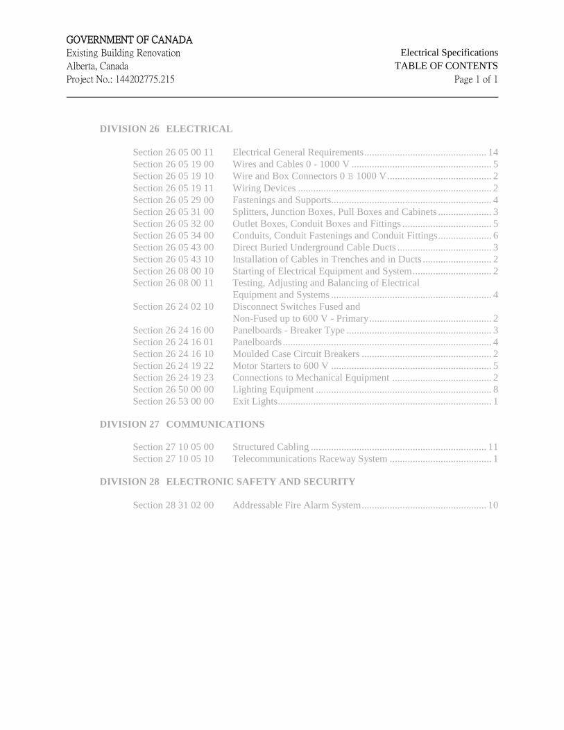
GOVERNMENT OF CANADA
Existing Building Renovation Electrical Specifications
Alberta, Canada TABLE OF CONTENTS
Project No.: 144202775.215 Page 1 of 1
DIVISION 26 ELECTRICAL
Section 26 05 00 11 Electrical General Requirements ................................................ 14
Section 26 05 19 00 Wires and Cables 0 - 1000 V ....................................................... 5
Section 26 05 19 10 Wire and Box Connectors 0 B 1000 V ......................................... 2
Section 26 05 19 11 Wiring Devices ............................................................................ 2
Section 26 05 29 00 Fastenings and Supports............................................................... 4
Section 26 05 31 00 Splitters, Junction Boxes, Pull Boxes and Cabinets ..................... 3
Section 26 05 32 00 Outlet Boxes, Conduit Boxes and Fittings ................................... 5
Section 26 05 34 00 Conduits, Conduit Fastenings and Conduit Fittings ..................... 6
Section 26 05 43 00 Direct Buried Underground Cable Ducts ..................................... 3
Section 26 05 43 10 Installation of Cables in Trenches and in Ducts ........................... 2
Section 26 08 00 10 Starting of Electrical Equipment and System ............................... 2
Section 26 08 00 11 Testing, Adjusting and Balancing of Electrical
Equipment and Systems ............................................................... 4
Section 26 24 02 10 Disconnect Switches Fused and
Non-Fused up to 600 V - Primary ................................................ 2
Section 26 24 16 00 Panelboards - Breaker Type ......................................................... 3
Section 26 24 16 01 Panelboards .................................................................................. 4
Section 26 24 16 10 Moulded Case Circuit Breakers ................................................... 2
Section 26 24 19 22 Motor Starters to 600 V ............................................................... 5
Section 26 24 19 23 Connections to Mechanical Equipment ....................................... 2
Section 26 50 00 00 Lighting Equipment ..................................................................... 8
Section 26 53 00 00 Exit Lights .................................................................................... 1
DIVISION 27 COMMUNICATIONS
Section 27 10 05 00 Structured Cabling ..................................................................... 11
Section 27 10 05 10 Telecommunications Raceway System ........................................ 1
DIVISION 28 ELECTRONIC SAFETY AND SECURITY
Section 28 31 02 00 Addressable Fire Alarm System ................................................. 10

GOVERNMENT OF CANADA Existing Building Renovation Section 26 05 00 11
Alberta, Canada ELECTRICAL GENERAL REQUIREMENTS
Project No.: 144202775.215 Page 1 of 15
1. GENERAL
1.1 Work Included
.1 Complete and operational electrical system as required by the drawings and as herein
specified.
1.2 Related Work
.1 General Requirements Division 01
.2 Equipment Division 11
.3 Mechanical Division 21, 22 and 23
1.3 Designation of Parties and Definition
.1 The following defines various items used within the Electrical Specification Division 26:
.1 ‘Engineer or Electrical Engineer’: This refers to Owner or Owner appointed
representative.
.2 ‘Electrical Trade of Contractor’: The Contractor undertaking to do the electrical
work described in the Electrical Specification and on the electrical drawings.
.3 ‘General Contractor or General Construction Trade’: The Contractor that has the
agreement with the Owner for the construction of the project.
.4 ‘Mechanical Trade or Mechanical Contractor’: Sub-contractors undertaking to
do the work described in the mechanical specifications and/or on the mechanical
drawings.
.5 ‘Provide’: Means supply and install or supply labour and materials required for
the installation of.
.6 ‘Approved Equal’: Items listed under Approved Manufacturer’s in specification
or addendum that shall be included in base bid.
.7 ‘Concealed’: Where used in connection with the installation of electrical
raceways and wiring, means that they are hidden from sight as in furred out
spaces, ceiling spaces, etc.
.8 ‘Exposed’: Where used in connection with the installation of electrical raceways
and wiring and electrical equipment, means that they are visible to persons within
the building.
GOVERNMENT OF CANADA Existing Building Renovation Section 26 05 00 11
Alberta, Canada ELECTRICAL GENERAL REQUIREMENTS
Project No.: 144202775.215 Page 2 of 15
1.4 Drawings and Specifications
.1 All work is to comply with the 2010 National Building Code and the 2014 Alberta
Building Code. The most stringent requirements/interpretations to be followed.
.2 The General Conditions, Supplementary Conditions and Division 01 are a part of this
specification and shall apply to this Division.
.3 The intent of the drawings and specifications is to include all labour, products and
services necessary for complete work, tested and ready for operation. Drawings and
specifications are complementary each to the other and what is called for by one shall be
binding as if called for by both.
.4 Symbols used to represent various electrical devices often occupy more space on the
drawing than the actual device does when installed. In such instances, do not scale
locations of devices from electrical symbols. Install these devices with primary regard
for usage of wall space, convenience of operation and grouping of devices.
.5 These specifications and the drawings and specifications of all other divisions shall be
considered as an integral part of the accompanying drawings. Any item or subject
omitted from either the specifications or the drawings but which is mentioned or
reasonably specified in and by the others, shall be considered as properly and sufficiently
specified and shall be provided.
.6 Provide all minor items and work not shown or specified but which are reasonably
necessary to complete the Work. Electrical drawings indicate general location and route
to be followed by conduit and/or wire and do not show all structural and mechanical
details. In some cases, conduit or wiring is not as shown on the plans or shown
diagrammatically on schematic or riser diagrams. Conduit and wire to be installed to
provide a complete operating job and to be installed physically to conserve headroom,
furring spaces, etc.
.7 If discrepancies or omissions in the drawings or specifications are found, or if the intent
or meaning is not clear, advise the Consultant for clarification before submitting tender.
.8 Responsibility to determine which Division provides various products and work rests
with the Contractor. Additional compensation will not be considered because of
differences in interpretation of specifications.
1.5 Quality Assurances
.1 Codes, Rules, Permits & Fees
.1 Comply with all laws, ordinances, rules, regulations, codes and orders of all
authorities having jurisdiction relating to this work.
.2 Comply with all rules of the Canadian Electrical Code, CSA Standard C22.1 and
the applicable building codes.
GOVERNMENT OF CANADA Existing Building Renovation Section 26 05 00 11
Alberta, Canada ELECTRICAL GENERAL REQUIREMENTS
Project No.: 144202775.215 Page 3 of 15
.3 Quality of work specified and/or shown on the drawings shall not be reduced by
the foregoing requirements.
.4 Give all required notices, submit drawings, obtain all permits, licenses and
certificates and pay all fees required for this work.
.5 Furnish a Certificate of Final Inspection and approvals from inspection authority
to the Consultant.
.2 Standards of Workmanship
.1 Execute all work in a competent manner and to present an acceptable appearance
when completed.
.2 Employ a competent supervisor (consistency is essential) and a sufficient number
of licensed tradesmen to complete the Work in the required time.
.3 Arrange and install products to fit properly into designated building spaces.
.4 Unless otherwise specified or shown, install products in accordance with
recommendations and ratings of manufacturers.
1.6 Submittals
.1 Within 30 days of award of contract, the contractor shall submit a completed equipment
procurement schedule which lists the manufacturer and model of equipment, indicating
the projected ordering, shop drawing submittal date and delivery dates of all products to
meet the required construction schedule.
.2 Submit samples as required where specified in Division 26.
.3 Prior to delivery of any products to job site and sufficiently in advance of requirements to
allow ample time for checking, submit shop drawings for review as specified in Division
01. Submit shop drawings for all equipment as required in each section of this
specification.
.4 Prior to submitting the shop drawings to the Consultant, the Contractor shall review the
shop drawings to determine that the equipment complies with the requirements of the
specifications and drawings.
.5 The term “shop drawing” means drawings, diagrams, illustrations, schedules,
performance characteristics, brochures and other data which are to be provided by the
Contractor to illustrate details of a portion of the Work.
Indicate materials, methods of construction and attachment of support wiring, diagrams,
connections, recommended installation details, explanatory notes and other information
necessary for completion of Work. Where equipment is connected to other equipment,
indicate that such items have been coordinated, regardless of the section under which the
GOVERNMENT OF CANADA Existing Building Renovation Section 26 05 00 11
Alberta, Canada ELECTRICAL GENERAL REQUIREMENTS
Project No.: 144202775.215 Page 4 of 15
adjacent items will be supplied and installed. Indicate cross-references to design
drawings and specifications.
Adjustments made on shop drawings by the Consultant are not intended to change the
contract price. If adjustments affect the value of the work state such in writing to the
Consultant prior to proceeding with the Work.
.6 Manufacture of products shall conform to revised shop drawings.
.7 Keep one complete set of shop drawings at job site during construction.
1.7 Record Drawings
.1 Refer to Section 01 77 00 Closeout Procedures – Operating and Maintenance Manuals
and Record Drawings.
.2 The Contractor shall keep one complete set of white prints at the site office, including all
addendums, change orders, site instructions, clarifications and revisions for the purpose
of record drawings. As the work on site proceeds, the Contractor shall clearly record in
Red Pencil all as-built conditions which deviate from the original contract documents.
Record drawings to include circuiting of all devices, conduit and feeder runs (complete
with conductor size and number) and locations of all electrical equipment. Include actual
room names and numbers on these drawings.
.3 Prior to substantial performance, the contractor shall obtain CAD files of all electrical
drawings, using AutoCAD, and use the services of a competent CAD operator to transfer
all as-built information, including: Addendums, Change Orders, Clarifications,
Revisions, Site Instructions and shop drawings. Upon completion, the contractor shall
certify, in writing, that the as-built record drawings are complete and that they accurately
indicate all electrical services, including exposed as well as concealed items.
.4 Contractor to forward letter of certification and as-built CAD drawings to the Consultant
for final review. As-Built drawings to be submitted in the form of one set of CAD files
on CD discs. Contractor is also to forward the hard copy red-lined as-built drawing to the
consultant.
.5 The contractor may borrow copies of the electrical contract drawings on disc from the
Consultant.
1.8 Operation and Maintenance Manuals
.1 Refer to Section 26 05 00 11 General Requirements.
.2 Provide hard copy and electronic copies of both Operating & Maintenance Manuals and
Record Drawings.
.3 Within 30 days prior to substantial performance, the Contractor shall submit a draft copy
of the proposed contents of each maintenance manual to the Consultant for review. Once
the draft copy is approved, the Contractor will supply 4 copies in suitably labelled, hard
back, D-Ring type commercial binders, each complete with an index and tabbed title

GOVERNMENT OF CANADA Existing Building Renovation Section 26 05 00 11
Alberta, Canada ELECTRICAL GENERAL REQUIREMENTS
Project No.: 144202775.215 Page 5 of 15
sheets for each section. Final copies of manuals to be received by Consultant not less
than 7 days prior to substantial performance.
.4 All maintenance manual data shall be printed on 8 1/2” x 11” heavy bond, indexed,
tabbed, punched and bound in the binders. each manual shall have a title sheet which is
labelled “Operation & Maintenance Manual”, and lists the Project name, Contractor’s &
Consultant’s names, date submitted, and a Table of Contents for each volume. If a
manual exceeds 75 mm in thickness, provide additional manuals as required.
.5 Provide an electronic version of complete manual.
.6 Each section of the manual shall contain the following information:
.1 Systems Descriptions. A brief synopsis of each system typed and inserted at the
beginning of each section. Include sketches and diagrams where appropriate.
.2 Descriptive and technical data.
.3 Maintenance and operating instructions for all electrical equipment and controls.
(These operating instructions need not be manufacturer's data but may be
typewritten instructions in simple language to guide the Owner in the proper
operation and maintenance of his installation.)
.4 Servicing intervals recommended.
.5 A copy of all wiring diagrams complete with wire coding.
.6 List of spare parts of all electrical equipment complete with names and addresses
of sales, service representatives and suppliers.
.7 Copy of data testing.
.8 Include type and accuracy of instruments used to obtain test data.
.9 Copy of final inspection certificate.
.10 Copy of the purchase order, showing equipment make and model numbers issued
to the manufacturer complete with all addendums. All cost details may be
hidden.
.11 Copy of all warranty certificates.
.12 Set of final reviewed Shop Drawings.
.13 Names, addresses, phone numbers and facsimile numbers of Contractor,
Consultants, sub-contractors and suppliers used on the Work together with a
specification reference of the portion of the Work they undertook.

GOVERNMENT OF CANADA Existing Building Renovation Section 26 05 00 11
Alberta, Canada ELECTRICAL GENERAL REQUIREMENTS
Project No.: 144202775.215 Page 6 of 15
1.9 Product Handling
.1 Use all means necessary to protect the products of this Division before, during and after
installation and to protect products and installed work of all other trades.
.2 Immediately make good any damage by repair or replacement at no additional cost to the
Owner and to the approval of the Consultant.
.3 Remove advertising labels from all electrical equipment. Do not remove identification of
certification labels.
.4 Remove dirt, rubbish, grease, etc. resulting from this work from all surfaces, including
the inside of all cabinets, equipment enclosures, panelboard tubs, etc.
1.10 Alternate and Separate Prices
.1 In accordance with the Instructions to Bidders, state on the Tender Form in the space
provided, the amount to be added or deleted from the base bid tender amount for the use
and installation of equipment as an alternate to those specified.
1.11 Guarantee
.1 Furnish a written guarantee to the Owner prior to final contract payment, which will be in
effect for one year from the date of final acceptance of the complete work. Replace or
repair at no cost to the Owner any defective material or workmanship except where, in
the opinion of the Consultant, such defects are due to the misuse or neglect by the Owner.
.2 This general guarantee shall not act as a waiver of any specified or special equipment
guarantees, which cover a greater length of time.
.3 Note: Certain sections of this Electrical Specification are subject to the following
warranty clause:
In the event of an emergency failure during the warranty period of any product(s),
material(s) or system(s) installed under this Section, and the issuer of the warranty is
unable to or chooses not to respond to a request by the owner for immediate emergency
repair/replacement of the affected product, material or system, then the owner reserves
the right to recover, from the issuer of the warranty, all costs incurred by the owner or
owner engaged forces in effecting the immediate repair/replacement.
1.12 Progress Claims
.1 Within thirty (30) days after award of contract, a breakdown of material and equipment
items including labour and expense components shall be compiled on the Consultant
format. Subsequent requests for payment shall be documented accordingly.
1.13 Waste Management and Disposal
.1 Separate and recycle waste materials.
GOVERNMENT OF CANADA Existing Building Renovation Section 26 05 00 11
Alberta, Canada ELECTRICAL GENERAL REQUIREMENTS
Project No.: 144202775.215 Page 7 of 15
.2 Collect and separate plastic, paper packaging and corrugated cardboard in accordance
with the Waste Management Plan.
.3 Fold up metal banding, flatten and place in designated area for recycling.
.4 Ensure emptied containers are sealed and stored safely for disposal away from children.
.5 Place materials defined as hazardous or toxic waste in designated containers.
.6 Collect, package and store any salvaged or remaining materials such as wire, conduit,
busbars, wireways, copper ground straps and other associated components for recycling
and reuse.
2. PRODUCTS
2.1 Selected Products & Equivalents
.1 Products and materials provided shall be new and free from all defects. Defective
products or materials will be rejected, regardless of previous inspections. The Contractor
shall be responsible to remove and replace defective products at their expense, and shall
be responsible for any resulting delays and associated expenses, which result from
defective products being rejected. Related materials shall be of the same manufacturer
throughout the project.
.2 Products and materials referred to in the specifications by trade names, manufacturer's
name and catalogue reference are those which shall be used as the basis for the Tender.
.3 The design has been based on the use of the specified product.
2.2 Alternative Products
.1 All product substitutions must be approved by the Consultant. Failure to obtain approval
from the Consultant will result in the alternative product being rejected, in which case the
Contractor shall provide an approved product at no additional cost to the owner.
.2 The Contractor shall assume full responsibility for ensuring that when providing
alternative products or materials, all space, weight, connections, power and wiring
requirements etc. are considered. Any costs incurred for additional components, changes
to services, structural or space requirements, layouts and plans, etc. that may be necessary
will be borne by the contractor.
.3 Suppliers to submit all requests for alternative product approval to the Consultant.
Submissions must be received by the Consultant not less than seven (7) working days
prior to the close of tenders. Submissions received after the “Cut-Off” date will not be
reviewed.
All submissions, which are approved by the Consultant, shall be identified as “Approved
Alternatives” in an Addendum. Alternative products not listed in the Addendum will be
rejected.
GOVERNMENT OF CANADA Existing Building Renovation Section 26 05 00 11
Alberta, Canada ELECTRICAL GENERAL REQUIREMENTS
Project No.: 144202775.215 Page 8 of 15
.4 Approval of an alternate is not intended to change the original specifications unless
specifically stated in the addenda. The submitter is responsible for all costs incurred by
other trades as well as his own, to install the product/system in accordance with the
contract documents.
.5 All submissions to be provided with technical data and whatever pertinent information
that may be required by the Consultant to evaluate equivalency to the specified product.
The responsibility to provide sufficient technical data with respect to submissions will
remain solely with those making the submission.
2.3 Quality of Products
.1 All products provided shall be CSA Approved, Canadian Underwriters' Laboratory
approved where applicable, and new, unless otherwise specified.
.2 If products specified are not CSA approved, obtain special approval from the local
regulatory authority. Pay all applicable charges levied and make all modifications
required for approval.
.3 Products provided, if not specified, shall be new, of a quality best suited to the purpose
required and their use subject to approval by the Consultant.
2.4 Uniformity of Manufacture
.1 Unless otherwise specifically called for in the Specifications, uniformity of manufacture
shall be maintained for similar products throughout the work.
2.5 Product Finishes
.1 Touch up all damaged painted finishes with matching lacquer, or, if required by the
Consultant, completely repaint damaged surface.
2.6 Use of Products During Construction
.1 Any equipment used for temporary or construction purposes shall be approved by the
Construction Manager and in accordance with the General Conditions, "Use of
Premises." Clean and restore to "as new" condition all equipment prior to the time of
substantial completion.
.2 The warranty period shall not begin until the date of substantial performance of the work.
3. EXECUTION
3.1 Site Examination
.1 Examine the site of work and become familiar with all features and characteristics
affecting this work before submitting tender.
GOVERNMENT OF CANADA Existing Building Renovation Section 26 05 00 11
Alberta, Canada ELECTRICAL GENERAL REQUIREMENTS
Project No.: 144202775.215 Page 9 of 15
.2 No additional compensation will be given for extra work due to existing conditions,
which such examination should have disclosed.
.3 Report to the Consultant any unsatisfactory conditions, which may adversely affect the
proper completion of this work.
3.2 Co-ordination with Other Divisions
.1 Examine the drawings and specifications of all divisions and become fully familiar with
their work. Before commencing work, obtain a ruling from the Consultant if any conflict
exists, otherwise no additional compensation will be made for any necessary adjustments.
.2 Lay out the work and equipment with due regard to architectural, structural and
mechanical features. Architectural and structural drawings take precedence over
electrical drawings regarding locations of walls, doors and equipment.
.3 Do not cut structural members without approval of the Consultant.
.4 Coordinate with all Division installing equipment and services, and ensure that there are
no conflicts.
.5 Install anchors, bolts, pipe sleeves, hanger inserts, etc. in ample time to prevent delays.
.6 Examine previously constructed work and notify the Consultant of any conditions, which
prejudice the proper completion of this work. Commencement of this work without such
notification shall constitute acceptance of other work.
3.3 Location of Outlets
.1 Electrical drawings are, unless otherwise indicated, drawn to scale and approximate
distances and dimensions may be obtained by scaling. Figured dimensions shall govern
over scaled dimensions. Where exact dimensions and details are required, refer to
Architectural drawings.
.2 Equipment locations shown on the drawings are approximate. Locations may be revised
up to 3 meters to suit construction and equipment arrangements without additional cost to
the Owner, provided that the Contractor is notified prior to the installation of the outlets,
or equipment.
.3 Unless otherwise specified or shown, install products in accordance with
recommendations and ratings of manufacturers.
3.4 Separation of Services
.1 Maintain separation between electrical wiring system and building piping, ductwork, etc.
so that wiring system is isolated (except at approved connections to such systems) to
prevent galvanic corrosion.
GOVERNMENT OF CANADA Existing Building Renovation Section 26 05 00 11
Alberta, Canada ELECTRICAL GENERAL REQUIREMENTS
Project No.: 144202775.215 Page 10 of 15
.2 In particular, contact between dissimilar metals, such as copper and aluminium, in damp
or wet locations is not permitted.
.3 Do not support wiring from pipes, ductwork, etc. Hangers for suspended ceilings may be
used for the support of wiring only when approval is obtained from the Consultant and
the ceiling installer, and approved clips or hangers are used.
3.5 Equipment Identification
.1 3 mm thick plastic lamacoid name plates, coloured face to match system colour, white
core, mechanically attached with self tapping screws, 6 mm high lettering, to be attached
to the front face of the following equipment:
.1 Starters, Contactors, Disconnects (Designation, voltage, load controlled)
.2 Colour code concealed conduits (including conduits above T-bar ceilings and under
raised floor), concealed junction and pull boxes, and metallic sheathed cables with paint
or plastic tape (25 mm wide band) at 15 metre intervals and at both side of transition
through walls. All conduit, junction boxes and pull boxes in service rooms to be colour
coded. Colour coding to be as follows:
SYSTEM MAJOR BAND MAJOR BAND
277/480V Normal Bronze
Standby Power Voltage Color with
‘SB’ identification White
120/208V Normal Grey
Fire Alarm System Red
Telephone Lt. Green
Building Alarm Pink
Commercial Television Dk. Brown
AV/TV Systems Lt. Brown
Clock System Yellow
Security Systems Dk. Green Lt. Brown
Door Intercom/Video Purple Yellow
Computers Black Yellow
.3 Provide neatly typed circuit directories in panelboards to indicate the area or equipment
controlled by each branch circuit.
.4 All conductors shall be identifiable by coloured insulation and permanent markers at
every terminal and accessible points throughout its entire run.
Conductors:
GOVERNMENT OF CANADA Existing Building Renovation Section 26 05 00 11
Alberta, Canada ELECTRICAL GENERAL REQUIREMENTS
Project No.: 144202775.215 Page 11 of 15
Equipment Grounding - Green
Neutral Conductor – White
277/480 Volt System 120/208 Volt System
Phase A - Orange Phase A - Red
Phase B - Brown Phase B - Black
Phase C - Yellow Phase C - Blue
Fire Alarm System
Neutrals White
Switch Legs Phase Colour with White Tracer
Speaker Cct. Blue with Yellow Tracer
Box Circuit Black with Yellow Tracer
Annunciator Brown with Yellow Tracer
.5 Low Voltage Wiring: per manufacturer's standard, i.e. CGE low voltage relay switching
system.
.6 Install yellow plastic warning tape, 300 mm below grade, above all underground ducts.
.7 Provide permanent, corrosion resistant warning markers, suitable to the local inspection
authority, imbedded in the surface of concrete slabs which are directly above high voltage
cables and duct banks.
.8 All housekeeping receptacles to be labelled with ‘HK’ on the cover plate.
3.6 Wiring to Equipment Supplied by Others
.1 Equipment supplied by the Owner or under other Division will be moved to the
installation site by others. However, the electrical connection to the equipment shall be
done by this Division.
3.7 Instructions to Owner's Personnel
.1 Refer to Section 26 08 00 12 - Electrical Equipment and Systems Demonstration and
Instruction.
3.8 Access Panels
.1 Where electrical equipment, junction boxes, remote ballasts or the like are concealed,
access panels shall be supplied. Panels shall be of adequate size for servicing of the
electrical work and complete with necessary frames and hinged doors held closed with
captive fasteners. Coordinate type and size of panels with the Consultant.
.2 In removable ceiling areas, provide markers on ceiling tile to locate equipment requiring
access. Markers shall be of a type approved by the Consultant.
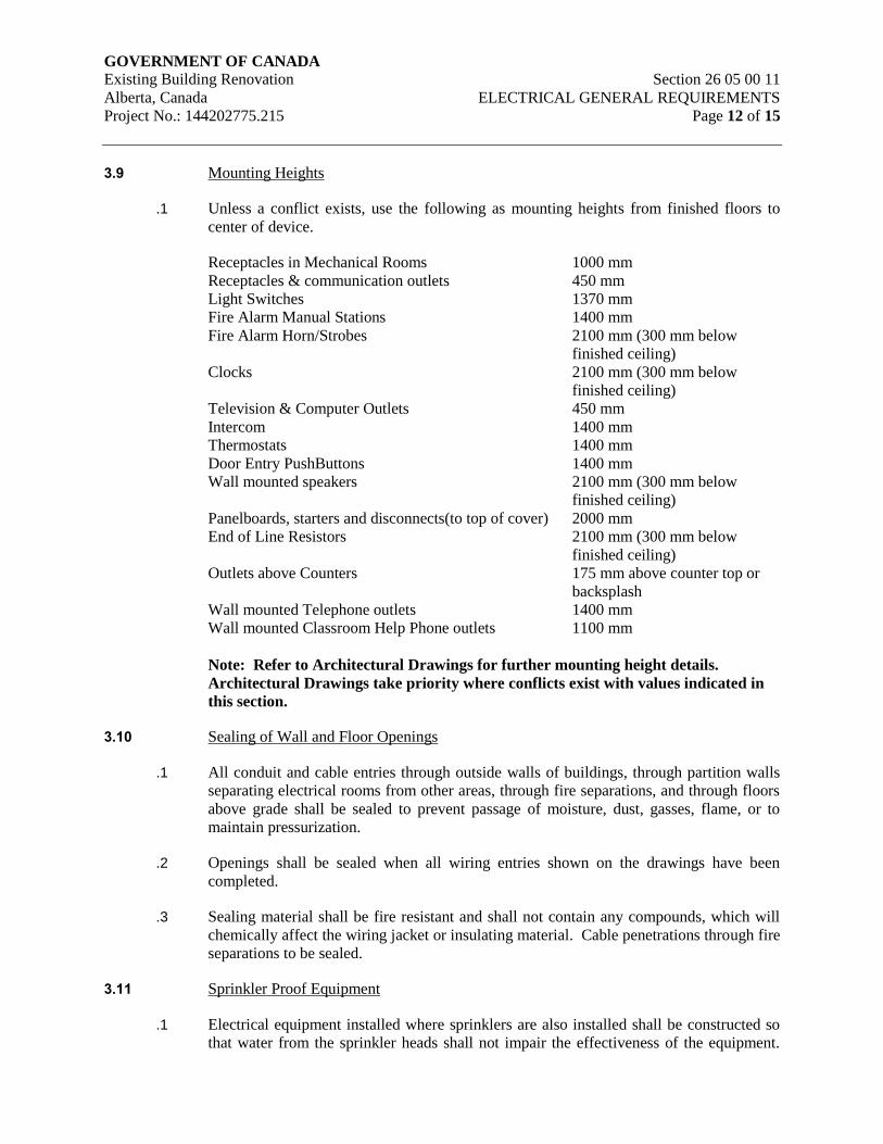
GOVERNMENT OF CANADA Existing Building Renovation Section 26 05 00 11
Alberta, Canada ELECTRICAL GENERAL REQUIREMENTS
Project No.: 144202775.215 Page 12 of 15
3.9 Mounting Heights
.1 Unless a conflict exists, use the following as mounting heights from finished floors to
center of device.
Receptacles in Mechanical Rooms 1000 mm
Receptacles & communication outlets 450 mm
Light Switches 1370 mm
Fire Alarm Manual Stations 1400 mm
Fire Alarm Horn/Strobes 2100 mm (300 mm below
finished ceiling)
Clocks 2100 mm (300 mm below
finished ceiling)
Television & Computer Outlets 450 mm
Intercom 1400 mm
Thermostats 1400 mm
Door Entry PushButtons 1400 mm
Wall mounted speakers 2100 mm (300 mm below
finished ceiling)
Panelboards, starters and disconnects(to top of cover) 2000 mm
End of Line Resistors 2100 mm (300 mm below
finished ceiling)
Outlets above Counters 175 mm above counter top or
backsplash
Wall mounted Telephone outlets 1400 mm
Wall mounted Classroom Help Phone outlets 1100 mm
Note: Refer to Architectural Drawings for further mounting height details.
Architectural Drawings take priority where conflicts exist with values indicated in
this section.
3.10 Sealing of Wall and Floor Openings
.1 All conduit and cable entries through outside walls of buildings, through partition walls
separating electrical rooms from other areas, through fire separations, and through floors
above grade shall be sealed to prevent passage of moisture, dust, gasses, flame, or to
maintain pressurization.
.2 Openings shall be sealed when all wiring entries shown on the drawings have been
completed.
.3 Sealing material shall be fire resistant and shall not contain any compounds, which will
chemically affect the wiring jacket or insulating material. Cable penetrations through fire
separations to be sealed.
3.11 Sprinkler Proof Equipment
.1 Electrical equipment installed where sprinklers are also installed shall be constructed so
that water from the sprinkler heads shall not impair the effectiveness of the equipment.
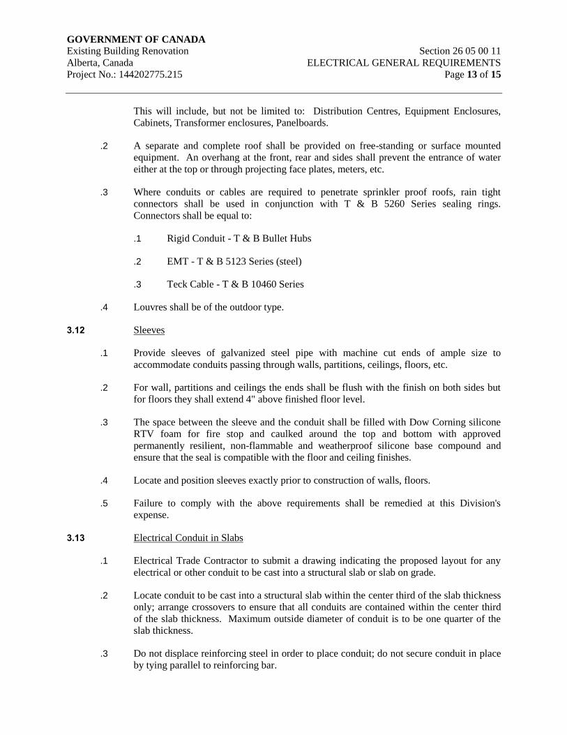
GOVERNMENT OF CANADA Existing Building Renovation Section 26 05 00 11
Alberta, Canada ELECTRICAL GENERAL REQUIREMENTS
Project No.: 144202775.215 Page 13 of 15
This will include, but not be limited to: Distribution Centres, Equipment Enclosures,
Cabinets, Transformer enclosures, Panelboards.
.2 A separate and complete roof shall be provided on free-standing or surface mounted
equipment. An overhang at the front, rear and sides shall prevent the entrance of water
either at the top or through projecting face plates, meters, etc.
.3 Where conduits or cables are required to penetrate sprinkler proof roofs, rain tight
connectors shall be used in conjunction with T & B 5260 Series sealing rings.
Connectors shall be equal to:
.1 Rigid Conduit - T & B Bullet Hubs
.2 EMT - T & B 5123 Series (steel)
.3 Teck Cable - T & B 10460 Series
.4 Louvres shall be of the outdoor type.
3.12 Sleeves
.1 Provide sleeves of galvanized steel pipe with machine cut ends of ample size to
accommodate conduits passing through walls, partitions, ceilings, floors, etc.
.2 For wall, partitions and ceilings the ends shall be flush with the finish on both sides but
for floors they shall extend 4" above finished floor level.
.3 The space between the sleeve and the conduit shall be filled with Dow Corning silicone
RTV foam for fire stop and caulked around the top and bottom with approved
permanently resilient, non-flammable and weatherproof silicone base compound and
ensure that the seal is compatible with the floor and ceiling finishes.
.4 Locate and position sleeves exactly prior to construction of walls, floors.
.5 Failure to comply with the above requirements shall be remedied at this Division's
expense.
3.13 Electrical Conduit in Slabs
.1 Electrical Trade Contractor to submit a drawing indicating the proposed layout for any
electrical or other conduit to be cast into a structural slab or slab on grade.
.2 Locate conduit to be cast into a structural slab within the center third of the slab thickness
only; arrange crossovers to ensure that all conduits are contained within the center third
of the slab thickness. Maximum outside diameter of conduit is to be one quarter of the
slab thickness.
.3 Do not displace reinforcing steel in order to place conduit; do not secure conduit in place
by tying parallel to reinforcing bar.
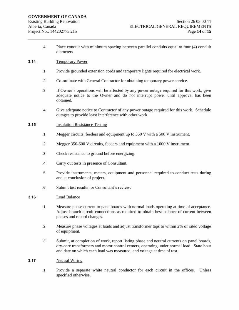
GOVERNMENT OF CANADA Existing Building Renovation Section 26 05 00 11
Alberta, Canada ELECTRICAL GENERAL REQUIREMENTS
Project No.: 144202775.215 Page 14 of 15
.4 Place conduit with minimum spacing between parallel conduits equal to four (4) conduit
diameters.
3.14 Temporary Power
.1 Provide grounded extension cords and temporary lights required for electrical work.
.2 Co-ordinate with General Contractor for obtaining temporary power service.
.3 If Owner’s operations will be affected by any power outage required for this work, give
adequate notice to the Owner and do not interrupt power until approval has been
obtained.
.4 Give adequate notice to Contractor of any power outage required for this work. Schedule
outages to provide least interference with other work.
3.15 Insulation Resistance Testing
.1 Megger circuits, feeders and equipment up to 350 V with a 500 V instrument.
.2 Megger 350-600 V circuits, feeders and equipment with a 1000 V instrument.
.3 Check resistance to ground before energizing.
.4 Carry out tests in presence of Consultant.
.5 Provide instruments, meters, equipment and personnel required to conduct tests during
and at conclusion of project.
.6 Submit test results for Consultant’s review.
3.16 Load Balance
.1 Measure phase current to panelboards with normal loads operating at time of acceptance.
Adjust branch circuit connections as required to obtain best balance of current between
phases and record changes.
.2 Measure phase voltages at loads and adjust transformer taps to within 2% of rated voltage
of equipment.
.3 Submit, at completion of work, report listing phase and neutral currents on panel boards,
dry-core transformers and motor control centers, operating under normal load. State hour
and date on which each load was measured, and voltage at time of test.
3.17 Neutral Wiring
.1 Provide a separate white neutral conductor for each circuit in the offices. Unless
specified otherwise.

GOVERNMENT OF CANADA Existing Building Renovation Section 26 05 00 11
Alberta, Canada ELECTRICAL GENERAL REQUIREMENTS
Project No.: 144202775.215 Page 15 of 15
3.18 Ground Wiring
.1 Provide a separate green ground conductor for each conduit run.
END OF SECTION
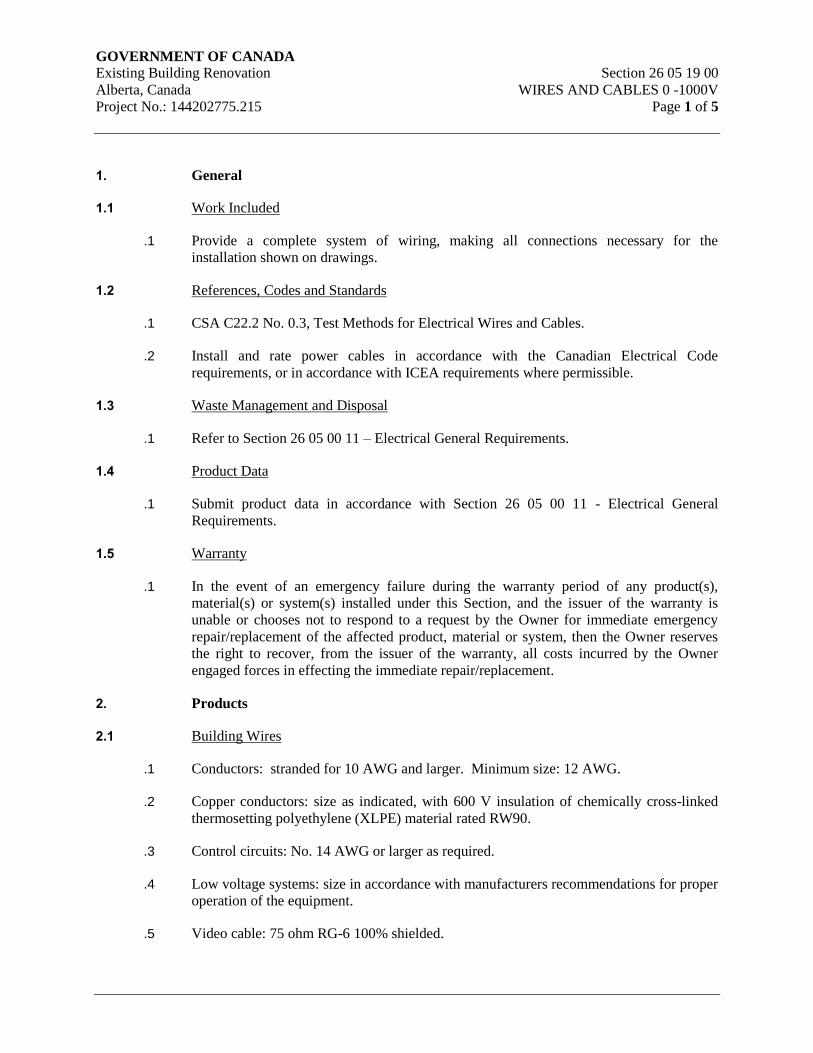
GOVERNMENT OF CANADA Existing Building Renovation Section 26 05 19 00
Alberta, Canada WIRES AND CABLES 0 -1000V
Project No.: 144202775.215 Page 1 of 5
1. General
1.1 Work Included
.1 Provide a complete system of wiring, making all connections necessary for the
installation shown on drawings.
1.2 References, Codes and Standards
.1 CSA C22.2 No. 0.3, Test Methods for Electrical Wires and Cables.
.2 Install and rate power cables in accordance with the Canadian Electrical Code
requirements, or in accordance with ICEA requirements where permissible.
1.3 Waste Management and Disposal
.1 Refer to Section 26 05 00 11 – Electrical General Requirements.
1.4 Product Data
.1 Submit product data in accordance with Section 26 05 00 11 - Electrical General
Requirements.
1.5 Warranty
.1 In the event of an emergency failure during the warranty period of any product(s),
material(s) or system(s) installed under this Section, and the issuer of the warranty is
unable or chooses not to respond to a request by the Owner for immediate emergency
repair/replacement of the affected product, material or system, then the Owner reserves
the right to recover, from the issuer of the warranty, all costs incurred by the Owner
engaged forces in effecting the immediate repair/replacement.
2. Products
2.1 Building Wires
.1 Conductors: stranded for 10 AWG and larger. Minimum size: 12 AWG.
.2 Copper conductors: size as indicated, with 600 V insulation of chemically cross-linked
thermosetting polyethylene (XLPE) material rated RW90.
.3 Control circuits: No. 14 AWG or larger as required.
.4 Low voltage systems: size in accordance with manufacturers recommendations for proper
operation of the equipment.
.5 Video cable: 75 ohm RG-6 100% shielded.
GOVERNMENT OF CANADA Existing Building Renovation Section 26 05 19 00
Alberta, Canada WIRES AND CABLES 0 -1000V
Project No.: 144202775.215 Page 2 of 5
.6 AC90 (BX) cable may only be utilized for recessed tee bar fixture drops from ceiling
mounted outlet boxes. Length of drops not to exceed 3.0 m (6’). Do not loop between
fixtures.
.7 Fire alarm cable: FAS
2.2 Teck Cable
.1 Conductors:
.1 Grounding conductor: copper.
.2 Circuit conductors: copper, size as indicated.
.2 Insulation:
.1 Chemically cross-linked thermosetting polyethylene rated type RW90, 600 V.
.3 Inner jacket: polyvinyl chloride material.
.4 Armour: interlocking galvanized steel.
.5 Overall covering: thermoplastic polyvinyl chloride material.
.6 Fastenings:
.1 One hole zinc straps to secure surface cables 50 mm and smaller. Two-hole steel
straps for cables larger than 50 mm.
.2 Channel type supports for two or more cables at 600 mm centers.
.3 6 mm diameter threaded rods to support suspended channels.
.7 Connectors:
.1 Watertight, approved for TECK cable.
2.3 Armoured Cables
.1 Conductors: insulated, copper, size as indicated.
.2 Type: AC90.
.3 Armour: interlocking type fabricated from aluminium strip.
.4 Type: ACWU90-PVC flame retardant jacket over thermoplastic armour meeting
requirements of Vertical Tray Fire Test of CSA C22.2 No. 0.3 with maximum flame
travel of 1.2 m.
GOVERNMENT OF CANADA Existing Building Renovation Section 26 05 19 00
Alberta, Canada WIRES AND CABLES 0 -1000V
Project No.: 144202775.215 Page 3 of 5
2.4 Control Cables
.1 Type LVT: 2 soft annealed copper conductors, sized as indicated, with thermoplastic
insulation, outer covering of armour of closely wound aluminium wire.
.2 Low energy 300 V control cable: solid annealed copper conductors sized as indicated,
with PVC insulation type.
3. Execution
3.1 General
.1 Minimum conductor size #12 AWG.
3.2 Installation of Building Wires
.1 Install wiring as follows:
.1 In conduit systems in accordance with Section 26 05 33.
3.3 Installation of Teck Cable 0 - 1000 V
.1 Install cables.
.2 Group cables wherever possible on channels.
.3 Terminate cables in accordance with Section 26 05 19 10 - Wire and Box Connectors - 0
- 1000 V.
3.4 Installation of Armoured Cables
.1 Group cables wherever possible.
.2 Terminate cables in accordance with Section 26 05 19 10 - Wire and Box Connectors - 0
- 1000 V.
.3 For ACWU cable, use non-magnetic connectors, ground armour and ground conductor at
supply and only use non-metallic cable entrance plates. Support runs on steel or
aluminium channels with spacers and clamps. Space cables to provide free air ampacity
ratings unless otherwise shown.
3.5 Installation of Control Cables
.1 Install control cables in cable troughs.
.2 Ground control cable shield.
3.6 Workmanship
.1 Before pulling wire, ensure conduit is dry and clean. If moisture is present, thoroughly
dry out conduits; vacuum if necessary. To facilitate pulling, recognized specially
GOVERNMENT OF CANADA Existing Building Renovation Section 26 05 19 00
Alberta, Canada WIRES AND CABLES 0 -1000V
Project No.: 144202775.215 Page 4 of 5
manufactured wire pulling lubricants may be used. Do not use grease. Employ suitable
techniques to prevent damage to wire when ambient temperature is below the minimum
permitted for each insulation type. Do not pull wires into incomplete conduit runs.
.2 Installation to be free of opens and grounds. Before energization, measure insulation
resistance and comply with the Canadian Electrical Code. Submit data sheet with values
measured.
.3 Do not install any conductor smaller than #12 AWG, except where specifically indicated
otherwise, i.e. for fire alarm system station circuits, etc.
.4 Provide sizes of conductors as shown on drawings. Voltage drop from lighting panels to
farthest outlet must not exceed 2% at full load in any case. Advise Consultant if problem
is foreseen.
.5 Exercise care in stripping insulation from wire. Do not nick conductors.
.6 Conductor length for parallel feeders to be identical.
.7 Lace or clip groups of feeder conductors at all distribution centres, pull boxes, and
termination points.
.8 All grounding conductor and straps to be copper. All ground conductors to have green
insulation jacket except where specified to be bare copper.
3.7 Identification, Coding and Balancing
.1 For branch circuit wiring, follow identification system shown on the drawings and as
specified in Section 26 05 00 11 - Electrical General Requirements.
.2 Connect single-phase equipment to minimize imbalance on feeders. Adjust branch
circuiting shown as required for optimum balancing. Record all changes on "record"
drawings.
.3 Colour code all feeders at all terminations, at all points where taps are made, and at all
panelboards, switchboards, motor control centres, etc. Use two wraps of 3M #471 plastic
film tape 48 mm wide.
.4 Conductors sized No. 10 and smaller are required to be factory coloured, not taped on
site.
.5 For direct current wiring use red for positive and black for negative.
3.8 Testing
.1 All power and control wiring shall be tested for insulation resistance value with a 1000
volt megger. Resistance values shall be as recommended by the cable manufacturer.
.2 All wire test results shall be properly tabulated, signed, dated, and submitted to the
Consultant.

GOVERNMENT OF CANADA Existing Building Renovation Section 26 05 19 00
Alberta, Canada WIRES AND CABLES 0 -1000V
Project No.: 144202775.215 Page 5 of 5
END OF SECTION
GOVERNMENT OF CANADA Existing Building Renovation Section 26 05 19 10
Alberta, Canada WIRE AND BOX CONNECTORS 0 -1000V
Project No.: 144202775.215 Page 1 of 2
1. General
1.1 Work Included
.1 Provide a complete system of wiring, making all connections necessary for the
installation shown on drawings.
1.2 Special Codes
.1 Install and rate power cables in accordance with the Canadian Electrical Code
requirements, or in accordance with IPCEA requirements where permissible.
1.3 References
.1 CSA C22.2 No. 65 Wire Connectors.
.2 EEMAC 1Y-2, Bushing Stud Connectors and Aluminum Adapters (1200 Ampere
Maximum Rating).
1.4 Waste Management and Disposal
.1 Refer to section 26 05 00 11 – Electrical General Requirements.
2. Products
2.1 Materials
.1 Pressure type wire connectors: with current carrying parts same material as conductors
sized to fit the conductors as required.
.2 Fixture type splicing connectors: with current carrying parts same material as conductors
sized to fit the conductors 10 AWG or less.
2.2 Wire Connectors
.1 Use self-insulated connectors for hand twist wire joints for lighting, small power, and
control wiring, or approved equal.
.2 Use non-insulated ring type compression lugs for terminating #10 AWG and smaller
motor connections. Tape with rubber and scotchtape. Lugs to accept ten - 32 x 3/8”
machine bolts.
.3 Terminate conductors #8 AWG and larger with Colour-Keyed compression connectors or
on lugs provided with equipment.
GOVERNMENT OF CANADA Existing Building Renovation Section 26 05 19 10
Alberta, Canada WIRE AND BOX CONNECTORS 0 -1000V
Project No.: 144202775.215 Page 2 of 2
3. Execution
3.1 Installation
.1 Remove insulation carefully from ends of conductors and:
.1 Apply coat of zinc joint compound on aluminum conductors prior to installation
of connectors.
.2 Install mechanical pressure type connectors and tighten screws with appropriate
compression tool recommended by manufacturer. Installation shall meet
secureness tests in accordance with CSA C22.2 No. 65.
.3 Install fixture type connectors and tighten. Replace insulating cap.
.4 Install bushing stud connectors in accordance with EEMAC 1Y-2.
3.2 Wire Connectors
.1 Select hand twist connectors for wire size and install tightly on conductors.
.2 Brush compound on terminations for compression connectors as recommended by the
manufacturer.
.3 Install compression connectors using methods and tools recommended by manufacturer.
.4 Do not install stranded conductors under screw terminals unless compression lugs are
installed.
END OF SECTION

GOVERNMENT OF CANADA Existing Building Renovation Section 26 05 19 11
Alberta, Canada WIRING DEVICES
Project No.: 144202775.215 Page 1 of 2
1. GENERAL
1.1 Work Included
.1 Provide and connect all wiring devices for the complete installation.
1.2 Waste Management and Disposal
.1 Refer to Section 26 05 00 11 – Electrical General Requirements.
2. PRODUCTS
2.1 Manufacturer
.1 Wiring devices to be of one manufacture throughout project.
.2 Manufacturers shall be Hubbell, Bryant or Arrow Hart.
2.2 Devices
.1 The catalogue numbers shown below are for the particular manufacturer's series and all
necessary suffixes shall be added for the requirements as stated. All devices shall be
specification grade minimum and wherever possible shall be of the same manufacture.
.2 Devices to be white with stainless steel, type 302 or 304 c/w No. 4 finish 1-mm thick
coverplates in all but mechanical areas (and Electrical Rooms) unless noted otherwise.
Use galvanized steel coverplates in mechanical areas (and Electrical Rooms) and for
surface mounted devices. UPS power to be orange.
2.3 Coverplates
.1 Use sheet steel utility box cover for wiring devices installed in surface mounted utility
boxes.
.2 Use stainless steel 1 mm thick coverplates on all wiring devices mounted in flush-
mounted outlet boxes unless otherwise specified.
.3 Weatherproof double lift spring - loaded cast aluminum coverplates, complete with
gaskets for single receptacles or switches.
.4 Weatherproof spring - loaded cast aluminum coverplates complete with gaskets for single
receptacles or switches.
.5 Use gasketted DS cast covers on FS and FD type boxes.
GOVERNMENT OF CANADA Existing Building Renovation Section 26 05 19 11
Alberta, Canada WIRING DEVICES
Project No.: 144202775.215 Page 2 of 2
3. EXECUTION
3.1 Installation
.1 Install single throw switches with handle in the "UP" position when switch closed.
.2 Install switches vertically in gang type outlet box when more than one switch is required
in one location.
.3 Mount switches on the latch side of the doorway as close as possible to door frame unless
otherwise indicated on drawings.
.4 Install receptacles vertically in gang type outlet box when more than one receptacle is
required in one location.
.5 Protect cover plate finish with paper or plastic film until all painting and other work is
finished, then remove paper.
.6 Install suitable common coverplates where wiring devices are grouped. Do not distort
plates by tightening screws excessively.
.7 Do not use coverplates meant for flush outlet boxes on surface mounted boxes.
.8 Wherever possible, mount equipment in a straight line at a uniform mounting height,
coordinated with other equipment and materials.
.9 Mounting dimensions are to the centre of the devices. Final instructions on mounting
heights shall be given by the Consultant’s representative at the site. The above shall be
used as a guide, but shall be subject to final verification prior to installation.
.10 Supply and install a separate neutral conductor for each branch circuit.
END OF SECTION
GOVERNMENT OF CANADA Existing Building Renovation Section 26 05 29 00
Alberta, Canada FASTENINGS AND SUPPORTS
Project No.: 144202775.215 Page 1 of 4
1. GENERAL
1.1 Work Included
.1 Supply and install all hangers and supports for the installation shown on the drawings and
specified herein, as necessary to fasten electrical equipment securely.
1.2 Related Work
.1 Material and Equipment - Fastenings and supports. Section 26 05 29
1.3 Waste Management and Disposal
.1 Refer to Section 26 05 00 11 – Electrical General Requirements.
2. PRODUCT
2.1 Framing and Support System
.1 Materials:
.1 Intermediate duty supporting structures shall employ P1000 Unistrut or equal
together with the manufactures connecting components and fasteners for a
complete system.
.2 Heavy duty supporting structures to be fabricated and welded from steel
structural members and prime painted before installation.
.2 Finishes:
.1 Outdoors, wet locations: Hot dipped galvanized.
.2 Indoors, dry locations: Galvanized when available, prime painted if not
available.
.3 Nuts, bolts, machine screws: Cadmium plated.
.3 Unistrut:
.1 Section P1000 or as required for load and span, with mounting screws, or
approved. P1000 or equal is a minimum standard for supporting conduits 50 mm
and larger.
2.2 Concrete and Masonry Anchors
.1 Materials: Hardened steel inserts, zinc plated for corrosion resistance. All anchor bolts
must be galvanized.
GOVERNMENT OF CANADA Existing Building Renovation Section 26 05 29 00
Alberta, Canada FASTENINGS AND SUPPORTS
Project No.: 144202775.215 Page 2 of 4
.2 Components: non-drilling anchors for use in predrilled holes, sized to safely support the
applied load with a minimum safety factor of four.
.3 Manufacturer: Hilti (Canada) Limited or approved equal.
2.3 Non-Metallic Anchors
.1 Material: Plastic anchors for sheet metal screws.
.2 Manufacturer: Fischer.
2.4 Conduit Supports
.1 General: Malleable iron one-hole conduit straps where exposed to weather. Stamped
steel two-hole straps indoors.
.2 Structural Steel: Crouse-Hinds “Wedgetite” supports or equivalent manufactured by
Appleton.
.3 Masonry, concrete, stone, etc.: Anchors.
.4 Title: Toggle bolts.
.5 Metal studs, ceiling hangers, etc.: “Caddy-Clips”.
.6 Unistrut: Unistrut conduit clamps.
2.5 Cable Supports and Clamps
.1 General: As per conduit supports, except that for single conductor cables, suitable non-
ferrous, or approved stainless steel or aluminum clamps shall be used.
3. Execution
3.1 General
.1 Do not cut or drill beams, joists or structural steel unless written permission of the
Consultants is obtained.
.2 Distance between conduit or cable supports not to exceed code requirements.
.3 Supports to be suitable for the real loads imposed by equipment.
.4 Supports to be securely fastened, free from vibration and excessive deflection or rotation.
Maximum deflections are 4 mm over a 1 meter span and 8 mm over a 2 meter span.
.5 Install fastenings and supports as required for each type of equipment cables and
conduits, and in accordance with manufacturer’s installation recommendations.
GOVERNMENT OF CANADA Existing Building Renovation Section 26 05 29 00
Alberta, Canada FASTENINGS AND SUPPORTS
Project No.: 144202775.215 Page 3 of 4
.6 Provide conduit rack with 25% spare capacity for multiple runs.
.7 Provide channel support with fittings for vertical runs of conduit and cables.
3.2 Installation
.1 Secure equipment to solid masonry, tile and plaster surfaces with lead anchors.
.2 Secure equipment to poured concrete with expandable inserts.
.3 Secure equipment to hollow masonry walls or suspended ceilings with toggle bolts.
.4 Support equipment, conduit or cables using clips, spring loaded bolts, cable clamps
designed as accessories to basic channel members.
.5 Fasten exposed conduit or cables to building construction or support system using straps.
.1 One-hole malleable iron or steel straps to secure surface conduits and cables 50
mm and smaller.
.2 Two-hole steel straps for conduits and cables larger than 50 mm.
.3 Beam clamps to secure conduit to exposed steel work.
.6 Suspended support systems.
.1 Support individual cable or conduit runs with 6 mm dia threaded rods and spring
clips.
.2 Support 2 or more cables or conduits on channels supported by 6 mm dia
threaded rod hangers where direct fastening to building construction is
impractical.
.7 Use plastic anchors for light loads only. Use metal anchors for all other loads.
.8 Shot driven pins may only be used with written approval of the structural engineer.
.9 Use round or pan head screws for fastening straps, boxes, etc.
.10 Do not support heavy loads from the bottom chord of open web steel joists.
.11 Support outlet boxes, junction boxes, panel tubs, etc., independent of conduits running to
them. Support conduits within 600 mm of outlet boxes. Support surface mounted panel
tubs with a minimum of four 6 mm fasteners.
.12 For surface mounting of two or more conduits use channels at 1.5 m oc spacing.
.13 Provide metal brackets, frames, hangers, clamps and related types of support structures
where indicated or as required to support conduit and cable runs.
GOVERNMENT OF CANADA Existing Building Renovation Section 26 05 29 00
Alberta, Canada FASTENINGS AND SUPPORTS
Project No.: 144202775.215 Page 4 of 4
.14 Ensure adequate support for raceways and cables dropped vertically to equipment where
there is no wall support.
.15 Do not use wire lashing or perforated strap to support or secure raceways or cables.
.16 Do not use supports or equipment installed for other trades for conduit or cable support
except with permission of other trade and approval of the Consultant.
.17 Support lay-in T-bar ceiling light fixtures withT-bar.
END OF SECTION

GOVERNMENT OF CANADA Section 26 05 31 00
Existing Building Renovation SPLITTERS JUNCTION BOXES
Alberta, Canada PULL BOXES AND CABINETS
Project No.: 144202775.215 Page 1 of 3
1. GENERAL
1.1 Work Included
.1 Provide a complete system of splitters boxes and cabinets for the installation of wiring
and equipment.
1.2 Shop Drawings and Product Data
.1 Submit shop drawings and product data for cabinets in accordance with
Section 26 05 00 11 Electrical General Requirements.
1.3 Warranty
.1 In the event of an emergency failure during the warranty period of any product(s),
material(s) or system(s) installed under this Section, and the issuer of the warranty is
unable or chooses not to respond to a request by the Owner for immediate emergency
repair/replacement of the affected product, material or system, then the Owner reserves
the right to recover, from the issuer of the warranty, all costs incurred by the Owner or
Owner engaged forces in effecting the immediate repair/replacement.
1.4 Waste Management and Disposal
.1 Refer to Section 26 05 00 11 – Electrical General Requirements.
2. PRODUCTS
2.1 Junction Boxes and Pull Boxes, Weatherproof
.1 Materials:
.1 Cast steel
2.2 Junction Boxes and Pull Boxes, Indoor Dry Locations
.1 Materials:
.1 Code gauge sheet steel, welded construction, phosphatized and factory paint
finish.
.2 Components:
.1 For flush mounting, covers to overlap box by 25 mm minimum all around with
flush head cover retaining screws.
.2 Use rolled edges for surface boxes.
.3 Junction boxes mounted in exterior walls shall be complete with box vapour barriers.
GOVERNMENT OF CANADA Section 26 05 31 00
Existing Building Renovation SPLITTERS JUNCTION BOXES
Alberta, Canada PULL BOXES AND CABINETS
Project No.: 144202775.215 Page 2 of 3
2.3 Cabinets
.1 Materials:
.1 Cabinets: Code gauge sheet steel, welded construction, phosphatized and factory
paint finish, suitable for field painting.
.2 Locks: to match panelboards.
.3 Backplates: 1.5 mm steel backplate, one piece per cabinet, covering entire
cabinet interior.
.2 Components:
.1 With hinged door and return flange overlapping sides, with handle, lock and
catch for surface mounting, size as indicated or to suit.
.2 Surface or flush with trim and hinged door, latch and lock and two keys, size as
indicated or to suit. Keyed to match panelboard keys.
2.4 Splitters
.1 Materials:
.1 Code gauge sheet steel, welded construction, phosphatized and factory paint
finish.
.2 Components:
.1 Formed hinged cover suitable for locking in the closed position.
.2 Main and branch lugs to match required size and number of incoming and
outgoing conductors as indicated.
.3 At least three spare terminals on each set of lugs in splitters less than 400 AMP.
2.5 Installation
.1 Junction Boxes and Pull Boxes:
.1 Supply all pull boxes and junction boxes shown on the drawings or required for
the installation. Maximum 30 m (100 feet) spacing.
.2 Boxes installed in party walls to be offset by a minimum of one stud space.
.3 Install in inconspicuous but accessible locations, above removable ceilings or in
electrical rooms, utility rooms or storage areas.
.4 Identify with system name and circuit designation as applicable.
.5 Size in accordance with the Canadian Electrical Code, as a minimum.
GOVERNMENT OF CANADA Section 26 05 31 00
Existing Building Renovation SPLITTERS JUNCTION BOXES
Alberta, Canada PULL BOXES AND CABINETS
Project No.: 144202775.215 Page 3 of 3
.2 Cabinets:
.1 Mount cabinets with top not greater than 1980 mm above finished floor,
coordinated with masonry, panelboards, fire hose cabinets and similar items.
Securely fasten backboards to cabinet interiors.
.2 Install terminal block where indicated.
.3 Splitters
.1 Install splitters and mount plumb, true and square to the building lines.
.2 Extend splitters full length of equipment arrangement except where indicated
otherwise.
.4 Identification
3. Provide equipment identification in accordance with Section 26 05 00 11- Electrical
General Requirements.
END OF SECTION
GOVERNMENT OF CANADA Existing Building Renovation Section 26 05 32 00
Alberta, Canada OUTLET BOXES, CONDUIT BOXES AND FITTINGS
Project No.: 144202775.215 Page 1 of 4
1. GENERAL
1.1 Work Included
.1 Provide a complete system of boxes for the installation of wiring and equipment.
1.2 References
.1 CSA C22.1-Canadian Electrical Codes, Part 1.
1.3 Waste Management and Disposal
.1 Refer to Section 26 05 00 11 – Electrical General Requirements.
2. PRODUCTS
2.1 Outlet and Conduit Boxes General
.1 Size boxes in accordance with CSA C22.1.
.2 102 mm square or larger outlet boxes as required for special devices.
.3 Gang boxes where wiring devices are grouped.
.4 Blank cover plates for boxes without wiring devices.
.5 Combination boxes with barriers where outlets for more than one system are grouped.
2.2 Outlet Boxes for Metal Conduit
.1 Materials:
.1 Surface or recessed concealed type: Die formed steel, hot dip galvanized, 1.25
oz/sq. ft. minimum zinc coating.
.2 Surface mounting exposed: Cast ferrous for threaded conduit, with attached lugs,
corrosion resistant two coats finish.
.2 Components:
.1 Ceiling outlets, surface mounting, concealed:
.1 101 mm square, depth 54 mm, Iberville 52171 series
.2 119 mm square, depth 54 mm, Iberville 72171 series
.2 Ceiling outlets, concealed mounting in concrete:
.1 101 mm octagonal concrete rings, depth from 38 mm to 152 mm
Iberville 54521 series.
GOVERNMENT OF CANADA Existing Building Renovation Section 26 05 32 00
Alberta, Canada OUTLET BOXES, CONDUIT BOXES AND FITTINGS
Project No.: 144202775.215 Page 2 of 4
.2 Wall boxes, concealed in concrete or masonry: for one and two gang
applications shall be 101 mm square, 54 mm deep, complete with
suitable square cornered raised tile wall cover for proper device and wall
surface application. Masonry boxes may be used for line voltage
switching.
.3 Wall outlets, concealed non-masonry construction, with plaster finish:
For one or two gangs used with switches, receptacles, etc., use 54 mm
deep, with matching plaster covers, depth to suit. Alternately, use 119
mm square boxes, and covers as required. (For more than two gangs use
solid boxes, or special boxes as required).
.4 Covers: Unless wiring devices and plates are mounted, provide blank,
round canopy covers to match boxes.
.5 For 277V switches: Non-interchangeable with 120V switches through
special tapped mounting ears, with top and bottom knockouts only.
2.3 Outlet Boxes for Rigid PVC Conduit
.1 Materials:
.1 Rigid PVC boxes and fittings: Unplasticized PVC.
2.4 Masonry Boxes
.1 Electro-galvanized steel masonry single and multi-gang boxes for devices flush mounted
in exposed block walls.
2.5 Concrete Boxes
.1 Electro-galvanized sheet steel concrete type boxes for flush mount in concrete with
matching extension and plaster rings as required.
2.6 Conduit Boxes
.1 Cast FS or FD aluminum boxes with factory-threaded hubs and mounting feet for any
surface wiring of switches and receptacle.
2.7
2.8 Fittings - General
.1 Bushing and connectors with nylon insulated throats.
.2 Knock-out fillers to prevent entry of debris.
.3 Conduit outlet bodies for conduit up to 32 mm and pull boxes for larger conduits.
.4 Double locknuts and insulated bushings on sheet metal boxes.
GOVERNMENT OF CANADA Existing Building Renovation Section 26 05 32 00
Alberta, Canada OUTLET BOXES, CONDUIT BOXES AND FITTINGS
Project No.: 144202775.215 Page 3 of 4
2.9 Service Fittings
.1 ‘High tension’ receptacle fitting made of 2 piece stainless steel with satin aluminum
housing finish for 1 duplex receptacles. Bottom plate with two knockouts for centered of
offset installation.
.2 Pedestal type ‘low tension’ fitting made of 2 piece stainless steel with satin aluminum
housing finish to accommodate two amphenol jack connectors.
3. execution
3.1 Installation
.1 Support boxes independently of connecting conduits.
.2 Fill boxes with paper, sponges or foam or similar approved material to prevent entry of
debris during construction. Remove upon completion of work.
.3 For flush installations mount outlets flush with finished wall using plaster rings to permit
wall finish to come within 6 mm of opening.
.4 Provide correct size of openings in boxes for conduit, mineral insulated and armoured
cable connections. Reducing washers are not allowed.
.5 Install all outlets flush and surface mounted as required for the installation.
.6 Surface mount above suspended ceilings, or in unfinished areas.
.7 Adjust position of outlets in finished masonry walls to suit course lines. Coordinate
cutting of masonry walls to achieve neat openings for all boxes.
.8 Do not distort boxes during installation. If boxes are distorted, replace with new boxes.
.9 Use plaster rings to correct depth. Use 30 mm on concrete block.
.10 Do not use sectional boxes.
.11 Provide boxes sized as required by the Canadian Electrical Code.
.12 Install vapour barrier material to surround and seal all outlet boxes located on exterior
walls of building. Maintain wall insulation.
.13 Outlets installed in party walls to be offset by a minimum of one stud space.
.14 Ceiling outlet boxes shall be provided for every surface mounted fixture or row of
fixtures installed on suspended "hard" ceilings.
.15 Primary bushings in termination box for cable connection.
.16 Secondary bushings in termination box for bus duct connection.
GOVERNMENT OF CANADA Existing Building Renovation Section 26 05 32 00
Alberta, Canada OUTLET BOXES, CONDUIT BOXES AND FITTINGS
Project No.: 144202775.215 Page 4 of 4
.17 Control junction box.
.18 Stainless steel nameplate and connection diagram.
.19 Where outlet boxes penetrate throughout a fire or smoke separation, ensure that they are
tightly fitted with non-combustible material to prevent passage of smoke or flame.
.20 No sectional or handy boxes to be installed.
4. Back boxes for all low voltage systems equipment to be provided in accordance with
specific manufacturer’s recommendations and as specified in the low voltage
sections of these specifications.
END OF SECTION
GOVERNMENT OF CANADA Section 26 05 34 00
Existing Building Renovation CONDUIT, CONDUIT
Alberta, Canada FASTENINGS AND CONDUIT FITTINGS
Project No.: 144202775.215 Page 1 of 6
1. GENERAL
1.1 Work Included
.1 Provide a complete system of conduit and fittings for installation of wiring.
1.2 Waste Management and Disposal
.1 Refer to Section 26 05 00 11 – Electrical General Requirements.
2. PRODUCTS
2.1 Rigid Steel Conduit
.1 Galvanized with threaded joints and connections.
.2 Connections in dry locations: steel or malleable iron locknuts inside and outside
enclosures.
.3 Connectors subjected to moisture interior and exterior: liquid and dust tight with
insulated throat.
.4 Fittings: cast metal including gasketted covers in damp locations.
.5 Expansion joints: cast metal Crouse-Hinds type XJ or approved alternate.
.6 minimum size to be 19mm.
2.2 E.M.T. Conduit
.1 Fittings in dry locations: Steel or zinc set screw connectors with insulated throat. Steel or
zinc set screw couplings.
.2 Fittings in wet locations: steel rain tight connectors with insulated throat. Steel rain tight
couplings.
.3 Minimum size to be 19 mm.
2.3 Rigid P.V.C. Conduit
.1 Conduit: rigid non-metallic conduit of unplasticized polyvinyl chloride as manufactured
Schedule 40.
.2 Fittings: threaded male or female solvent weld connectors and solvent weld couplings, as
supplied by conduit manufacturer.
.3 Solvent: Solvents to have Volatile Organic Compound (VOC) limits of less than 285g/L
less water and less exempt compounds as per the State of California’s South Coast Air
Quality Management District (SCAQMD) current.
GOVERNMENT OF CANADA Section 26 05 34 00
Existing Building Renovation CONDUIT, CONDUIT
Alberta, Canada FASTENINGS AND CONDUIT FITTINGS
Project No.: 144202775.215 Page 2 of 6
2.4 Rigid PVC Duct
.1 Duct: Rigid non-metallic conduit of unplasticized polyvinyl chloride Type DB-2,
conforming to CSA Standard.
.2 Accessories: Bell ends, couplings, adapters, bends and other fittings of same material as
duct. Use solvent recommended by manufacturer. Horizontal, vertical and foundation
spacers.
.3 Solvent: Solvents to have Volatile Organic Compound (VOC) limits of less than 285g/L
less water and less exempt compounds as per the State of California’s South Coast Air
Quality Management District (SCAQMD) current.
2.5 Liquid-Tight Flexible Conduit
.1 Conduit: flexible metal conduit with liquid-tight PVC jacket.
.2 Connectors: captive sealing jacket and ground cone insulated throat, steel.
.3 Minimum size to be 19 mm.
2.6 Electrical Non-metallic Tubing (ENT)
.1 To CSA C22.2 N0. 227.1, Electrical Non-metallic Tubing
3. EXECUTION
3.1 Rigid Steel Conduit
Use as raceways for following applications:
.1 In all areas exposed to weather.
.2 Locations where mechanical damage may occur and in mechanical rooms to a height
of 1 metre.
.3 Three phase motor wiring (Teck cable may also be used for this application where shown
on the drawings).
3.2 E.M.T. Conduit
.1 Use as raceways for following applications:
.1 In surface and concealed areas or in poured concrete above ground level.
.2 It may not be used in damp locations, corrosive atmosphere, underground, outdoors, nor
in areas exposed to mechanical damage.
3.3 E.N.T. Conduit
.1 Use as raceways for following applications:
GOVERNMENT OF CANADA Section 26 05 34 00
Existing Building Renovation CONDUIT, CONDUIT
Alberta, Canada FASTENINGS AND CONDUIT FITTINGS
Project No.: 144202775.215 Page 3 of 6
.1 In concrete floor slabs and where not subject to mechanical injury either during
or after construction. Minimum size shall be 25mm (1”)In surface and concealed
areas or in poured concrete above ground level.
3.4 Rigid P.V.C. Conduit
.1 Use as raceways for following applications
.1 In poured concrete floors and walls and on underground runs exterior to the
buildings unless otherwise noted.
.2 Wiring installed in areas subject to intermittent or continuous moisture but not
surface mounted.
.3 Rigid PVC conduit shall not be surface mounted.
.2 Use strictly in accordance with the Canadian Electrical Code. Do not use in return air
plenums and for exit and fire escape lights.
.3 Provide insulated ground wire in all rigid PVC conduits in accordance with the Canadian
Electrical Code.
.4 Where rigid PVC conduit is set in poured concrete, solvent joints must be completed and
allowed to set as per manufacturer's instructions.
.5 Bend rigid conduit in strict accordance with manufacturer's directions. Distorted bends
will not be accepted.
3.5 Rigid PVC Duct
.1 Provide a separate green insulated copper ground wire in all ducts sized as required by
the Code.
.2 Arrange ducts in a horizontal layer separated by plastic spacers to provide spacing
between duct centres, as shown on the drawings.
.3 Support duct bank on plastic spacers 35 mm between ducts. Foundation spacers to
maintain at least 76 mm clearance between ducts and exterior coverage.
.4 Make joints with tapered couplings to provide a secure watertight connection. Stagger all
joints to provide 200 mm vertical and horizontal clearance between adjacent couplings.
Where needed, use factory bends to provide bends of radius required.
.5 When all ducts are installed, brace whole assembly at each spacer group to prevent duct
floating when concrete is placed.
.6 Terminate ducts with standard bell ends where ducts enter cable pits, junction boxes and
building interiors.
.7 Cap ends of unused ducts with plug ends of same material as ducts.
GOVERNMENT OF CANADA Section 26 05 34 00
Existing Building Renovation CONDUIT, CONDUIT
Alberta, Canada FASTENINGS AND CONDUIT FITTINGS
Project No.: 144202775.215 Page 4 of 6
.8 Seal all joints in ducts with solvent cement.
3.6 Liquid-Tight Flexible Conduit
.1 Use as raceways for following applications:
.1 At all motors, pipe mounted control devices, and other devices subject to
movement or water.
.2 At all motors provide a short length before connecting to the motor terminal box.
Minimum length shall be 450 mm plus 4 times the conduit diameter.
.3 Provide a separate ground wire within flexible conduit, bonded to motor frames and
system ground.
3.7 Workmanship
.1 Install all conduit and wiring concealed, unless otherwise shown on the drawings. Do not
recess conduit in columns, except as noted, without permission.
.2 Where conduit is run exposed, run parallel to building lines. Where conduits are grouped
(two or more), space evenly, make bends concentric.
.3 Reuse existing concealed conduit in ceiling concrete slab as much as possible for feeding
of power to lighting fixtures and to avoid surface run conduit as the existing slab will be
exposed and there will be not dropped ceiling system.
.4 Lay out conduit to avoid interference with other work. Maintain a minimum clearance of
150 mm from steam or hot water piping, vents, etc.
.5 Slabs on grade: Install rigid PVC conduit in the gravel base below concrete slabs.
Provide mechanical protection around stub-ups through slab and extend 150 mm beyond
concrete. When rigid steel conduit is installed in contact with earth it shall be protected
by Polykin #940 tape. Extend taping 300 mm above finished grade.
.6 Metal conduit installations in concrete pours: Tie down conduit to prevent shifting. All
joints are to be made up tight to ensure ground continuity. To prevent concrete entry,
seal EMT set screw fittings with tape, pack outlet boxes and cap conduit terminations
both in boxes and stub-ups. Apply Polykin #940 tape to the conduit 152 mm both sides
of the point of leaving slab.
.7 Do not place conduit in concrete slabs in which slab thickness is less than four times
conduit diameter. Place conduits larger than this size under floor. Conduits to have
minimum 25 mm concrete cover.
.8 Organize conduit in slabs to minimize crossovers. Obtain approval and minimum
concrete cover required from structural engineer prior to installing conduits in slabs.
.9 At all recessed panels cap 2 - 25 mm and 4 - 19 mm empty conduits from panel into
ceiling above future use.
GOVERNMENT OF CANADA Section 26 05 34 00
Existing Building Renovation CONDUIT, CONDUIT
Alberta, Canada FASTENINGS AND CONDUIT FITTINGS
Project No.: 144202775.215 Page 5 of 6
.10 Provide Brady underground warning tapes 300 mm below grade above all underground
conduits. Tape shall be yellow warning tape, 150 mm wide.
.11 Where conduits or ducts enter or exit concrete structures below grade provide 16 mm x
1500 mm steel reinforcing dowels to prevent shearing. Extend dowel 1000 mm beyond
concrete and band conduit to dowel. The first 3 meter length of conduit extending from
the structure to be Polykin wrapped rigid steel.
.12 Where conduit is installed in floor slabs to run up at equipment or motors, carefully check
all conduit locations. Verify conduit locations for mechanical equipment from shop
drawings or detail drawings. Brace all stub-ups. Stub-ups shall be rigid steel.
.13 Where steel conduit is required to be bent, do not heat, and do not bend conduit in such a
way as to reduce pipe cross section area at any point. Radii of bends shall be as per
Canadian Electrical Code.
.14 For all runs of conduits, do not include more than equivalent of 4 - quarter bends.
Provide conduit fittings, pullboxes and junction boxes where necessary. Pulling elbows
shall not be used except by special permission.
.15 Where possible, install conduits so that they are not trapped, cap turned up conduits to
prevent the entrance of dirt of moisture during construction. Swab out conduit and
thoroughly clean internally before wires and cables are pulled.
.16 Take extreme care in reaming ends of all conduit to ensure a smooth interior finish that
will not damage the insulation of the wires.
.17 Use insulated non-metallic bushings on all conduit terminations.
.18 Ensure electrical continuity in all conduit systems.
.19 All conduits shown exposed in finished areas is to be free of unnecessary labels and trade
marks.
.20 Install a 90 lb. test line in all conduits left empty by this contractor including those which
others will pull cables, wires, etc.
.21 Conduits and ducts crossing building expansion joints shall have conduit expansion
fittings to suit the type of conduit used, and shall be Crouse-Hinds, Sceptre, or approved
fitting.
.22 Seal conduits with duct seal where conduits are run between heated and unheated areas.
Where conduits, cables, or cable trays pierce fire separations, seal openings with Dow
Corning 3-6548 sealant or approved equal.
.23 Where conduits pass through walls, they shall be grouped and installed through openings.
After all conduits shown on the drawings are installed, wall openings shall be closed with
material compatible with the wall construction. Review size and quantity of conduit
sleeves with the Consultant.
GOVERNMENT OF CANADA Section 26 05 34 00
Existing Building Renovation CONDUIT, CONDUIT
Alberta, Canada FASTENINGS AND CONDUIT FITTINGS
Project No.: 144202775.215 Page 6 of 6
.24 Where drawings show conduit designations, these conduits shall be identified at each
point of termination with Thomas & Betts "Ty-Rap" No. TY532M labels.
.25 Where conduit finish is damaged, repair or replace.
.26 Use "Condulet" fittings for power and telephone type conduit terminations in lieu of
boxes where support is not provided.
.27 All branch circuit wiring and home-runs to be a minimum of 19 mm and communication
and data to be minimum 25 mm diameter unless otherwise stated.
.28 Where possible install conduit in equipment roof curbs. If roof penetrations are required,
provide necessary flashing and pitch pockets, making watertight joints where conduits
pass through roof or watertight membranes.
.29 Where panelboard branch circuit conduits are amalgamated, size shall not exceed 38 mm
diameter.
.30 Where conduits pass through fire separations, seal with approved fire sealing compound.
.31 Maximum run of conduit shall not exceed 30 m. Provide pull boxes at a minimum of
every 30 m.
.32 Allow no more than a maximum of two (2) 90 degree bends between pull boxes.
.33 All telecommunications conduits shall be bonded to ground.
.34 All conduit bends shall be sweep type bends with the inside radius not less than six (6)
times the diameter for conduits 50 m and smaller and ten (10) times the diameter for
conduits 65 mm and larger.
.35 All conduits stubbed into telecom rooms shall be turned up or down as appropriate and
terminated at the edge of the plywood backboards. Terminate conduit stubs with an
insulated grounding bushing and cap.
4. Provide a separate ground conductor in each conduit.
END OF SECTION

GOVERNMENT OF CANADA Existing Building Renovation Section 26 05 43 00
Alberta, Canada DIRECT BURIED UNDERGROUND CABLE DUCTS
Project No: 144202775.215 Page 1 of 3
1. GENERAL
1.1 Work Included
.1 Provide complete system of underground ducts, fittings and turn-ups for the installation
indicated on the drawings.
1.2 Related Work
.1 Excavation and backfilling: Division 2
.2 Concrete Work: Division 3
.3 Plumbing and Drainage: Division 3
1.3 Waste Management and Disposal
.1 Refer to Section 26 05 00 11 – Electrical General Requirements.
2. Products
2.1 Rigid P.V.C. Duct
.1 Duct: Rigid non-metallic conduit of unplasticized polyvinyl chloride type EB-1 requiring
concrete encasement, type DB-2 heavier wall for direct burial without concrete
encasement, conforming to CSA Standard B196.1, manufactured by Canron Plastics Ltd,
or IPEX inc. Nominal length 6 m plus or minus 12 mm with minimum wall thickness at
any point of 3.0 mm.
.2 Accessories: Bell ends, couplings, reducers, plugs, caps, adaptors, bends and other
fittings of same materials as duct. Use solvent weld compound as recommended by
manufacturer. Horizontal, vertical and foundation spacers as manufactured by IPEX inc.
.3 Expansion Joints as required.
2.2 Cable Pulling Equipment
.1 6 mm stranded nylon pull rope tensile strength 5 kN.
2.3 Duct Spacers
.1 Plastic spacers to suit installation shown, manufactured by IPEX. Minimum distance
between conduits shall be 190mm centre-to-centre.
2.4 Markers
.1 Concrete type cable markers: As indicated, with words; “cable’, “joint’ or “conduit”
impressed in top surface, with arrows to indicate change in direction of duct runs.
GOVERNMENT OF CANADA Existing Building Renovation Section 26 05 43 00
Alberta, Canada DIRECT BURIED UNDERGROUND CABLE DUCTS
Project No: 144202775.215 Page 2 of 3
2.5 Solvents
.1 Solvent: Solvents to have Volatile Organic Compound (VOC) limits of less than 285g/L
less water and less exempt compounds as per the State of California’s South Coast Air
Quality Management District (SCAQMD) current edition.
3. Execution
.1 Install underground ducts for wiring systems as shown on the drawings and as per
manufacturer’s instructions.
.2 Clean inside of duct before laying.
.3 Provide a separate green insulated copper ground wire in all ducts, even if not shown,
except for conduits from a utility transformer into service entrance equipment. Use
Canadian Electrical Code to size ground wire.
.4 Furnish minimum of 85% of total footage of each size in standard lengths of 6 meters or
3 meters. Remainder of each size may be furnished in random lengths, but not less than
1.5 meters.
.5 Arrange ducts in horizontal layers separated by plastic spacers to provide horizontal and
vertical spacing between duct centres, as shown on drawings. Stack spacers vertically
above each other and install in at least two groups per 10’ length of duct. Minimum
distance between conduits shall be 190mm centre-to-centre.
.6 Support duct bank on plastic foundation spacers on same centre lines as tier separators.
Foundation spacers to maintain at least 75 mm clearance between ducts and trench
bottom or mud mat. Ensure full, even support every 1.5 m throughout duct length.
.7 Make joints with tapered couplings to provide a secure watertight connection. At
locations where coupling is loosely fitted to produce a slight change of direction of the
duct run, thoroughly waterproof joint with a coating of solvent compound. Stagger all
joints to provide 200 mm vertical and horizontal clearance between adjacent couplings.
Where needed, use bender to provide bends of radius required.
.8 Make bell and spigot joints. Drive ducts together as recommended by manufacturer to
produce a solid watertight connection. Stagger all joints to provide 200 mm vertical and
horizontal clearance between adjacent couplings. Where needed, use manufactured
bends to provide bends of radius required.
.9 When all ducts are installed, brace whole assembly at each spacer group to prevent duct
floating when concrete is placed.
.10 Use adaptors and connect duct to a 90-degree rigid, heavy-wall, steel conduit bend where
conduit rises above ground.
.11 Terminate ducts with standard bell ends where ducts enter manholes, cable pits, junction
boxes and building interiors.
GOVERNMENT OF CANADA Existing Building Renovation Section 26 05 43 00
Alberta, Canada DIRECT BURIED UNDERGROUND CABLE DUCTS
Project No: 144202775.215 Page 3 of 3
.12 Pull through each duct steel, wooden or plastic mandrel not less than 300 mm long and of
diameter 6 mm less than the internal diameter of duct, following by stiff bristle brush to
remove sand, earth and other foreign matter. Pull stiff bristle brush through each duct
immediately before pulling in cables.
.13 In each duct install pull rope continuous throughout each duct run with 3 m spare rope at
each end.
.14 Plug ends of unused spare ducts with plugs of same material as ducts.
.15 Seal all joints in ducts with solvent cement.
.16 Install marker as required.
.17 Ensure lines and levels for underground ducts are set to obtain proper drainage, coverage,
separation, etc. Ensure such conditions are met prior to proceeding with work.
.18 Construct duct runs to provide at least 750 mm from top of concrete encasement to
finished surface above. Grade duct runs between manholes, vaults, cable pits and
buildings to ensure proper drainage. Minimum slope shall be 75 mm per 30 m. Provide
grades and slopes shown on drawings. Depths of cover shown on electrical drawings are
minimum; greater depths may result from grading of ducts.
.19 Install ducts in accordance with additional requirements of utility or service company
having jurisdiction.
END OF SECTION
GOVERNMENT OF CANADA Section 26 05 43 10
Existing Building Renovation INSTALLATION OF CABLES IN
Alberta, Canada TRENCHES AND IN DUCTS
Project No.: 144202775.215 Page 1 of 2
1. GENERAL
1.1 Related Work
.1 Excavation and Backfilling: Division 02
1.2 Waste Management and Disposal
.1 Refer to Section 26 05 00 11 – Electrical General Requirements.
2. PRODUCTS
2.1 Cable Protection
.1 38 x 140 mm planks pressure treated with clear copper napthenate or 5%
pentachlorophenol solution, water repellent preservative.
2.2 Markers
.1 Concrete type cable markers: 600 x 600 x 100 mm with words: “cable”, “joint” or
“conduit” impressed in top surface, with arrows to indicate change in direction of cable
and duct runs.
3. EXECUTION
3.1 Cable Installation in Ducts
.1 Install cables as indicated in ducts.
.2 Do not pull spliced cables inside ducts.
.3 Install multiple cables in duct simultaneously.
.4 Use CSA approved lubricants of type compatible with cable jacket to reduce pulling
tension.
.5 To facilitate matching of colour coded multiconductor control cables reel off in same
direction during installation.
.6 Before pulling cable into ducts and until cables properly terminated, seal ends of cables
with moisture seal tape.
.7 After installation of cables, seal duct ends with duct sealing compound.
3.2 Markers
.1 Mark cable every 150 m along duct runs and changes in direction.
.2 Where markers are removed to permit installation of additional cables, reinstall existing
markers.
GOVERNMENT OF CANADA Section 26 05 43 10
Existing Building Renovation INSTALLATION OF CABLES IN
Alberta, Canada TRENCHES AND IN DUCTS
Project No.: 144202775.215 Page 2 of 2
3.3 Field Quality Control
.1 Perform tests in accordance with Section 26 08 00 11 - Testing, Adjusting and Balancing
of Electrical Equipment and Systems.
.2 Perform tests using qualified personnel. Provide necessary instruments and equipment.
.3 Check phase rotation and identify each phase conductor of each feeder.
.4 Check each feeder for continuity, short circuits and grounds. Ensure resistance to ground
of circuits is not less than 50 megohms.
.5 Pre-acceptance test.
.1 After installing cable but before splicing and terminating, perform insulation
resistance test with 1000 V megger on each phase conductor.
.2 Check insulation resistance after each splice and/or termination to ensure that
cable system is ready for acceptance testing.
.6 Acceptance Tests
.1 Ensure that terminations and accessory equipment are disconnected.
.2 Ground shields, ground wires, metallic armour and conductors not under test.
.3 High Potential (Hipot) Testing.
.1 Conduct hipot testing in accordance with manufacturer’s
recommendations.
.4 Provide Consultant with list of test results showing location at which each test
was made, circuit tested and result of each test.
4. Remove and replace entire length of cable if cable fails to meet any of test criteria.
END OF SECTION

GOVERNMENT OF CANADA Section 26 08 00 10
Existing Building Renovation STARTING OF ELECTRICAL
Alberta, Canada EQUIPMENT AND SYSTEM
Project No.: 144202775.215 Page 1 of 2
1. GENERAL
1.1 Related Work
.1 Testing, Adjusting and Balancing of Electrical Equipment
and Systems Section 26 08 00 11
.2 Electrical Equipment and Systems Demonstration and
Instruction Section 26 08 00 12
1.2 Coordination
.1 Coordinate starting of electrical equipment and systems with testing, adjusting and
balancing, and demonstration and instruction of:
.1 Electrical equipment and systems specified in Division 26.
.2 Mechanical equipment and systems specified in Division 21, 22 and 23.
.3 Other equipment and systems specified in other Divisions.
.2 Where any equipment or system requires testing, adjusting or balancing prior to starting,
ensure that such work has been completed prior to starting of electrical equipment and
systems.
2. products
(Not used)
3. execution
3.1 Energizing Electrical System
.1 Prior to energizing main electrical system:
.1 Verify supply authority voltage and phase rotation.
.2 Close and open all devices to ensure proper mechanical operation.
3.2 Starting Motors
.1 Prior to starting motors:
.1 Verify phase rotation at motor control centres.
.2 Confirm motor nameplate data with motor starter heater overloads.

GOVERNMENT OF CANADA Section 26 08 00 10
Existing Building Renovation STARTING OF ELECTRICAL
Alberta, Canada EQUIPMENT AND SYSTEM
Project No.: 144202775.215 Page 2 of 2
3.3 Energizing Equipment
.1 Prior to energizing equipment provided under other Sections and equipment provided by
others. Confirm equipment nameplate data with characteristics of power supply.
END OF SECTION
GOVERNMENT OF CANADA Section 26 08 00 11
Existing Building Renovation TESTING, ADJUSTING AND BALANCING OF
Alberta, Canada ELECTRICAL EQUIPMENT AND SYSTEMS
Project No.: 144202775.215 Page 1 of 4
PART 1 - GENERAL
1.1 Intent
.1 Except where otherwise specified, arrange and pay for testing, adjusting, balancing and
related requirements specified herein.
.2 If test results do not conform with applicable requirements, repair, replace, adjust or
balance equipment and systems. Repeat testing as necessary until acceptable results are
achieved.
.3 Provide all labour, materials, instruments and equipment necessary to perform the tests
specified.
.4 All tests shall be witnessed by persons designated by the Owner, who shall also sign the
test documentation.
.5 Submit procedures proposed in writing for approval two (2) weeks prior to test.
1.2 Related Work
.1 Electrical General Requirements Section 26 05 00 11
.2 Starting of Electrical Systems and Equipment Section 26 08 00 10
1.3 Manufacturer's Production Test Records
.1 If requested, submit copies of production test records for production tests required by
EEMAC and CSA standards for manufactured electrical equipment.
1.4 Site Testing Reports
.1 Log and tabulate test results on appropriate test report forms.
.2 Submit forms to Consultant for approval prior to use.
.3 Submit completed test report forms as specified, immediately after tests are performed.
1.5 Reference Documents
.1 Perform tests in accordance with:
.1 The Contract Documents
.2 Requirements of authorities having jurisdiction
.3 Manufacturer's published instructions
.4 Applicable CSA, IEEE, IPCEA, EEMAC and ASTM standards

GOVERNMENT OF CANADA Section 26 08 00 11
Existing Building Renovation TESTING, ADJUSTING AND BALANCING OF
Alberta, Canada ELECTRICAL EQUIPMENT AND SYSTEMS
Project No.: 144202775.215 Page 2 of 4
.2 If requirements of any of the foregoing conflict, notify Consultant before proceeding with
test and obtain clarification.
1.6 Manufacturer's Site Services
.1 Arrange and pay for the site services of qualified manufacturer's representatives where
site testing, adjusting, or balancing of electrical equipment or systems' performed by
Manufacturer's representatives is:
.1 Specified, or
.2 Otherwise required to ensure that electrical equipment and systems are
operational in full compliance with the Contract Documents
1.7 Sequencing and Scheduling
.1 Except where otherwise specified, perform all testing, adjusting, balancing and related
requirements specified herein prior to Interim Acceptance of the Work.
.2 Perform voltage testing and adjusting after user occupancy or utilization of facility.
PART 2 - PRODUCTS
2.1 Test Equipment
.1 Provide all equipment and tools necessary to perform testing, adjusting and balancing
specified herein and as otherwise required.
PART 3 - EXECUTION
3.1 Fused and Unfused Disconnect Switches
.1 Visually inspect and clean.
.2 Ductor test across switch blade contact surfaces.
.3 Megger test.
.4 Mechanical function test.
3.2 Lighting
.1 Function test all light switches, luminaires, dimmers and lighting control equipment such
as photo-cells, daylight sensors, occupancy sensors and time clock settings.
.2 Prior to energizing line and low voltage lighting control system, ensure manufacturer has
checked all equipment and wiring for proper installation and termination. Manufacturer
to check that all pre-set levels are set and operate as specified.
.3 Check operation of all emergency lighting units and exit lights.
GOVERNMENT OF CANADA Section 26 08 00 11
Existing Building Renovation TESTING, ADJUSTING AND BALANCING OF
Alberta, Canada ELECTRICAL EQUIPMENT AND SYSTEMS
Project No.: 144202775.215 Page 3 of 4
.4 Record all settings for all lighting control devices such as time clock, sensors, etc.
3.3 Communications Cabling
.1 Check installation of all equipment.
.2 Ensure all cables are properly identified at each end and correctly terminated prior to
testing.
3.4 Testing of Wiring and Wiring Devices
.1 Test conductors at distribution centres and panelboards for insulation resistance to ground
(megger test).
.2 Test service grounding conductors for ground resistance.
.3 Test all wiring devices for correct operation and circuitry.
3.5 Communication Cabling Testing
.1 Test all runs upon completion of permanent terminations as described in
Section 27 10 05.
.
3.6 Fire Alarm System Testing - General
.1 Refer to Section 26 05 00 11 - Electrical General Requirements.
.2 Consultant will be responsible for directing verification of fire alarm system installation
in accordance with:
.1 CAN/ULC-S537, Standard for Verification of Fire Alarm System Installations,
and Requirements of authority having jurisdiction.
.3 Contractor shall be responsible for:
.1 Performing prerequisites to verification procedure; and
.2 Assisting and cooperating with Consultant in verification procedure
3.7 Fire Alarm System Testing - Prerequisites to Verification
.1 Prior to requesting verification by Consultant, do the following:
.1 Inspect system to ensure that the following items are completely installed,
connected and fully operational in accordance with requirements of the Contract
Documents and Manufacturer's recommendations:
.1 All new fire detection and signaling devices
.2 All other auxiliary equipment connected to fire alarm system
GOVERNMENT OF CANADA Section 26 08 00 11
Existing Building Renovation TESTING, ADJUSTING AND BALANCING OF
Alberta, Canada ELECTRICAL EQUIPMENT AND SYSTEMS
Project No.: 144202775.215 Page 4 of 4
.2 Ensure that operation and maintenance data has been submitted.
.2 Submit written request to Consultant for verification, certifying that the above
prerequisites have been fulfilled and specifying known exceptions in the form of a list of
items to be completed, corrected or submitted.
.3 Consultant will, within two (2) weeks after receipt of written request:
.1 Proceed with verification, or
.2 Advise contractor that prerequisites are not adequately fulfilled
3.8 Fire Alarm System Testing - Verification
.1 The contractor and manufacturer shall assist and cooperate with Consultant in
verification procedure. The contractor shall provide and pay for the following:
.1 Provide the following equipment:
.1 Voltmeter
.2 Sound pressure level meter
.3 Smoke generator or aerosol test smoke
.4 Four (4) portable communication devices
.5 Scaffolding and ladders
.6 Heat Bucket for setting off heat detectors
.2 Arrange and ensure that the following parties are present at all times during
verification procedures:
.1 Electrical Subcontractor
.2 Fire alarm system manufacturer's representative
.3 Disassemble and reassemble system components
.4 Disconnect and reconnect wiring
.5 Perform required field adjustments
.6 Repair defective work and replace defective components
.7 Perform all work and tests on system required by verification procedure.
.2 Do not proceed with verification unless Consultant's representative responsible for
directing verification procedure is present.
END OF SECTION
GOVERNMENT OF CANADA Section 26 24 02 10
Existing Building Renovation DISCONNECT SWITCHES FUSED AND
Alberta, Canada NON FUSED UP TO 600V PRIMARY
Project No.: 144202775.215 Page 1 of 2
1. general
1.1 Description
.1 Provide disconnect switches for 120/208 volt distribution as indicated on the drawings, as
manufactured by Cutler Hammer, Schnieder or Square D.
1.2 Waste Management and Disposal
.1 Refer to Section 26 05 00 11 – Electrical General Requirements.
2. products
2.1 Disconnect Switches
.1 Ratings: 240 volts for 120/208 volt distribution. Unless otherwise shown, 3 pole for 3
phase, 3 wire distribution, 3 pole and solid neutral for 3 phase 4 wire distribution.
Ampere ratings as shown on the drawings or to suit load requirements. For motors, use
disconnect switches with HP ratings at least equal to motor HP.
.2 Enclosures: CSA code gauge galvanized steel, hinged doors, external operating handles.
Disconnect switches in dry locations shall be EEMAC-1 and EEMAC-3 where exposed
to weather. Provide ON-OFF switch position indication on switch enclosure cover.
.3 Finish: One primer coat and one finish coat on all metal surfaces, colours as per Section
26 05 00 11 - Electrical General Requirements.
.4 Switch mechanisms: Quick make and quick break action with self wiping contacts,
solderless pressure lug connectors. For switches 100 amperes and over, provide non-
tracking arc shrouds. All switch poles to operate together from a common operating bar.
Provide for padlocking disconnect switches in "Off" position. Doors to be interlocked
and complete with defeat mechanism, to prevent opening when handle in ON position.
.5 Neutral Bars: Where distribution system has grounded neutral conductor, provide neutral
bar where required with ampere rating equal to switch rating, in enclosure. Provide
ground bar for terminating ground conductors.
.6 Fuse Holders: Provide fuse holders (relocatable and suitable without adapters) on load
side of switches, ampere rating equal to switch ratings, suitable for fuses specified.
2.2 Fuses
.1 All fuses to be 100,000 ampere (minimum) interrupting capacity of the current limiting
type. In addition, fuses feeding motors to be of the time delay type. Provide one full set
of spare fuses, three for each different ampere rating used, stored in suitable enclosure.
GOVERNMENT OF CANADA Section 26 24 02 10
Existing Building Renovation DISCONNECT SWITCHES FUSED AND
Alberta, Canada NON FUSED UP TO 600V PRIMARY
Project No.: 144202775.215 Page 2 of 2
3. execution
3.1 Disconnect Switches
.1 Mounting: Provide supports independent of conduits. Wall mounts where possible,
otherwise provide Unistrut frame support. Where switches are grouped, mount in
uniform arrangement.
.2 Wiring: Connect line and load cable to all switches.
.3 Fuse Rating: Install so that rating is visible.
.4 Identification: Provide lamacoid plate in accordance with Section 26 05 00 11 -
Electrical General Requirements, on each switch showing voltage, source of supply and
load being fed, for example:
.1 Door Controller
.2 120/208 Volts
.3 Fed from PPA
END OF SECTION
GOVERNMENT OF CANADA Existing Building Renovation Section 26 24 16 00
Alberta, Canada PANELBOARD – BREAKER TYPE
Project No.: 144202775.215 Page 1 of 3
1. General
1.1 Related Work
.1 Rough Carpentry - Fire Rated Plywood Backboard Division 26
1.2 Shop Drawings
.1 Submit shop drawings in accordance with Section 26 05 00 11 - Electrical General
Requirements.
.2 Drawings to include electrical detail of panel, branch breaker type, quantity, ampacity
and enclosure dimension.
1.3 Waste Management and Disposal
.1 Refer to Section 26 05 00 11 – Electrical General Requirements.
2. Products
2.1 Panelboards
.1 Panelboards: product of one manufacturer.
.1 Install circuit breakers in panelboards before shipment.
.2 In addition to CSA requirements manufacturer's nameplate must show fault
current that panel including breakers has been built to withstand.
.2 208V panelboards: bus and breakers rated interrupting capacity as indicated on drawings.
.3 Sequence phase bussing with odd numbered breakers on left and even on right, with each
breaker identified by permanent number identification as to circuit number and phase.
.4 Panelboards: mains, number of circuits, and number and size of branch circuit breakers as
indicated.
.5 Two keys for each panelboard and key panelboards alike.
.6 Copper bus with neutral of same ampere rating as mains.
.7 Mains: suitable for bolt-on breakers.
.8 Trim with concealed front bolts and hinges.
.9 Trim and door finish: baked grey enamel.
GOVERNMENT OF CANADA Existing Building Renovation Section 26 24 16 00
Alberta, Canada PANELBOARD – BREAKER TYPE
Project No.: 144202775.215 Page 2 of 3
2.2 Custom Built Panelboard Assemblies
.1 Double stack panels as indicated.
.2 Contactors in mains as indicated.
.3 Feed through lugs as indicated.
.4 Isolated ground bus.
2.3 Breakers
.1 Breakers: to Section 26 24 16 10 - Moulded Case Circuit Breakers.
.2 Breakers with thermal and magnetic tripping in panelboards except as indicated
otherwise.
.3 Main breaker: separately mounted on top or bottom of panel to suit cable entry. When
mounted vertically, down position should open breaker.
.4 Lock-on devices for 10% of 15 to 30A breakers installed as indicated. Turn over unused
lock-on devices to Owner.
2.4 Equipment Identification
.1 Provide equipment identification in accordance with Section 26 05 00 11 - Electrical
General Requirements.
.2 Nameplate for each panelboard size 4 engraved as indicated.
.3 Nameplate for each circuit in distribution panelboards size 2 engraved as indicated.
.4 Complete circuit directory with typewritten legend showing location and load of each
circuit.
3. Execution
3.1 Installation
.1 Locate panelboards as indicated and mount securely, plumb, true and square, to adjoining
surfaces.
.2 Install surface mounted panelboards on plywood backboards. Where practical, group
panelboards on common backboard.
.3 Mount panelboards to height specified in Section 26 05 00 11 - Electrical General
Requirements or as indicated.
.4 Connect loads to circuits.

GOVERNMENT OF CANADA Existing Building Renovation Section 26 24 16 00
Alberta, Canada PANELBOARD – BREAKER TYPE
Project No.: 144202775.215 Page 3 of 3
.5 Connect neutral conductors to common neutral bus with respective neutral identified.
END OF SECTION
GOVERNMENT OF CANADA Existing Building Renovation Section 26 24 16 01
Alberta, Canada PANELBOARDS
Project No.: 144202775.215 Page 1 of 4
1. GENERAL
1.1 Description
.1 This section covers the providing and installation of distribution panelboards.
1.2 Related Documents
.1 All sections of the Bidding Requirements, contract Conditions and Division 1 are part of
this section.
.2 Applicable sections of Division 16 are part of this section of the Specifications.
2. PRODUCTS
2.1 Panelboards, Circuit Breaker Type, 208/120 Volt, 3 Phase 4 Wire
.1 Manufacturers: Square D, Siemens, General Electric, or Cutler-Hammer
.2 Shall be dead front type with flush or surface mounted steel cabinet as required and an
internal assembly of circuit breakers. Trims shall have hinged and locked doors with
glass or heavy plastic covered circuit directories. All locks shall be keyed alike. Boxes
shall be galvanized, and front assembly shall be painted with a prime and a finish coat of
manufacturer=s standard finish. Panels shall have 3 phase, 4 Wire, solid neutral mains of
capacities indicated on the Drawings with main lugs or main circuit breaker as required.
.3 Panelboards shall have suitable gutter space to accommodate separate neutrals conductors
for all branch circuits.
.4 Circuit breakers shall be molded plastic case type, quick-make, quick-break, with trip
free common operating handle, position indication and common trip from thermal-
magnetic trip device. Trip ratings shall be as indicated on the Drawings and minimum
interrupting capacity shall be 22,000 RMS symmetrical amperes at 240 volts.
2.2 Distribution Switchboards
.1 Manufacturers: Square D, Siemens, General Electric, or Cutler-Hammer
.2 Ratings
.1 The assembly shall be rated to withstand mechanical forces exerted during short-
circuit conditions when connected directly to a power source having available
fault current 65,000 amperes symmetrical at 240 volts.
.2 The switchboard shall operate at 208 volts a.c., three-phase, four-wire. The main
bus shall be rated as noted on the drawings. Each switchboard shall have both a
neutral and ground bar
GOVERNMENT OF CANADA Existing Building Renovation Section 26 24 16 01
Alberta, Canada PANELBOARDS
Project No.: 144202775.215 Page 2 of 4
.3 Construction
.1 Switchboards shall consist of the required number of vertical sections bolted
together to form a rigid assembly. All edges of front covers or hinged front
panels shall be formed. Provide adequate ventilation within the enclosure
.2 All sections of the switchboard shall be front and rear aligned. All protective
devices shall be group mounted. Devices shall be front removable and load
connections front accessible.
.3 The assembly shall be provided with adequate lifting means.
.4 Bus
.1 All bus bars shall be silver-plated copper. Main horizontal bus bars shall be
mounted with all three phases arranged in the same vertical plane. Bus sizing
shall be based on NEMA standard temperature rise criteria of 65 degrees C over
a 40 degrees C ambient (outside the enclosure).
.2 A copper ground bus (minimum 1/4 x 2 inch), shall be furnished firmly secured
to each vertical section structure and shall extend the entire length of the
switchboard.
.3 All hardware used on conductors shall be high-tensile strength and zinc-plated.
All bus joints shall be provided with conical spring-type washers.
.5 Wiring/Terminations
.1 Mechanical-type terminals shall be provided for all line and load terminations
suitable for copper or aluminum cable rated for 75 degrees C of the size as
indicated on the drawings.
.2 Lugs shall be provided in the incoming line section for connection of the main
grounding conductor. Additional lugs for connection of other grounding
conductors shall be provided as indicated on the drawings.
.3 Each switchboard shall have a neutral bar with incoming terminations equal to
the phase terminations and load side terminations equal to the terminations of the
switchboard load switches.
.6 Quick-Make/Quick-Break Fusible Switches
.1 Protective devices shall be quick-make/quick-break fusible switches. Fusible
switches 30 amperes through 600 amperes frames shall be furnished with
rejection class "R" or "J" type fuse clips unless otherwise scheduled. Fusible
switches 800 amperes through 1600 amperes shall be furnished with class L fuse
clips. Switches shall incorporate safety cover interlocks to prevent opening the
cover with the switch in the ON position or prevent placing the switch in the ON
position with the cover open. Provide defeater for authorized personnel. Handles
GOVERNMENT OF CANADA Existing Building Renovation Section 26 24 16 01
Alberta, Canada PANELBOARDS
Project No.: 144202775.215 Page 3 of 4
shall have provisions for padlocking and shall clearly indicate the ON or OFF
position. Front cover doors shall be padlockable in the closed position.
.7 Circuit Breakers
.1 Circuit breakers shall be molded plastic case type, quick-make, quick-break, with
trip free common operating handle, position indication and common trip from
thermal-magnetic trip device. Trip ratings shall be as indicated on the Drawings
and minimum interrupting capacity shall be 65,000 RMS symmetrical amperes at
240 volts.
.8 Enclosures
.1 NEMA 1 Enclosure
.9 Nameplates
.1 Engraved nameplates, mounted on the face of the assembly, shall be furnished
for all main and feeder circuits as indicated on the drawings. Nameplates shall be
laminated plastic, black characters on white background. Characters shall be
3/16-inch high, minimum. Nameplates shall give item designation and circuit
number as well as frame ampere size and appropriate trip rating. Furnish master
nameplate giving switchboard designation, voltage ampere rating, short-circuit
rating, manufacturer's name, general order number, and item number.
.10 Finish
.1 All exterior and interior steel surfaces of the switchboard shall be properly
cleaned and provided with a rust-inhibiting phosphatized coating.
.11 Metering
.1 Each switchboard shall have a microprocessor based meter installed complete
with current transformers. The meter shall read and display all line-to-line and
line-to-neutral voltages, current in each phase, power factor, power in kW,
apparent power in kVA, kW demand, current peak demand, kW peak demand,
kVA peak demand. The demand time shall be adjustable and the peak demand
readings shall be resettable with a password. The unit shall be able to
communicate via Ethernet. Provide three licensed copies of any software
required to read the meter.
.2 A terminal strip shall be provided for the termination of the data cable.
.3 The meter shall be powered from the 208 volts in the switchboard.
GOVERNMENT OF CANADA Existing Building Renovation Section 26 24 16 01
Alberta, Canada PANELBOARDS
Project No.: 144202775.215 Page 4 of 4
.4 Provide a disconnect means to disconnect the phase leads to the meter from the
power source.
.5 Provide fuses in a fuse holder for the power into the meter.
2.3 Fuses
.1 Fuses shall be Bussman, Low Peak sized according to the drawings.
.2 Provide three spare fuses of each size and type.
3. EXECUTION
3.1 Installation
.1 Panelboards shall be surface mounted in electrical rooms or flush mounted where
indicated on plan drawings.
.2 Mount panelboards directly to concrete walls.
.3 Mount panelboards to finished walls using unistrut channels, minimum two channels per
box.
.4 Install panelboards plumb and level.
.5 Install all switchboards on 4” concrete housekeeping pads.
3.2 Grounding
.1 Bond all panelboards per N.E.C.
3.3 Identification
.1 Provide name plates.
.2 Paint panelboards.
3.4 Fault And Coordination Study
.1 The manufacturer of the switchboards shall provide a fault and coordination study of the
distribution system down to the load side of all distribution panels. The manufacturer
shall use this study to select fuses and circuit breakers so that they coordinate. This study
shall be provided with the shop drawing submittals. The engineer reserves the right to
request changes in the devices at shop drawing time.
END OF SECTION
GOVERNMENT OF CANADA Existing Building Renovation Section 26 24 16 10
Alberta, Canada MOULDED CASE CIRCUIT BREAKERS
Project No.: 144202775.215 Page 1 of 2
PART 1 - GENERAL
1.1 Product Data
.1 Submit product data in accordance with Section 26 05 00 11 - Electrical General
Requirements.
.2 Include time-current characteristic curves for breakers with interrupting capacity of
22,000 A symmetrical (rms) and over at system voltage.
1.2 Waste Management and Disposal
.1 Refer to Section 26 05 00 11– Electrical General Requirements.
PART 2 - PRODUCTS
2.1 Breakers General
.1 Bolt-On Moulded Case Circuit Breaker: Quick-make, quick-break type, for manual and
automatic operation with temperature compensation for 40°C ambient.
.2 Common-Trip Breakers: With single handle for multi-pole applications.
.3 Magnetic instantaneous trip elements in circuit breakers to operate only when value of
current reaches setting. Trip settings on breakers with adjustable trips to range from 3 to
8 times current rating.
.4 Circuit breakers with interchangeable trips as indicated.
.5 Provide solid-state tripping system for all breakers larger than 225 amps with long, short,
instantaneous function and ground fault protection.
2.2 Thermal Magnetic Breakers
.1 Moulded case circuit breaker to operate automatically by means of thermal and magnetic
tripping devices to provide inverse time current tripping and instantaneous tripping for
short circuit protection.
2.3 Optional Features
.1 Include where indicated on drawings:
.1 Shunt trip.
.2 Auxiliary switch.
.3 On-off locking device
.4 Handle mechanism.
.5 Non-auto.

GOVERNMENT OF CANADA Existing Building Renovation Section 26 24 16 10
Alberta, Canada MOULDED CASE CIRCUIT BREAKERS
Project No.: 144202775.215 Page 2 of 2
PART 3 - EXECUTION
3.1 Installation
.1 Install circuit breakers as indicated.
.2 Identification: Provide lamicoid plate on CDP cover housing the breaker showing
voltage and load being fed. Example - 120/208 V, 3 phase, 4W to Splitter Trough No. 1.
END OF SECTION
GOVERNMENT OF CANADA Existing Building Renovation Section 26 24 19 22
Alberta, Canada MOTOR STARTERS TO 600V
Project No.: 144202775.215 Page 1 of 5
1. General
1.1 References
.1 IEC 947-4-1, Part 4: Contactors and motor-starters.
1.2 Related Work
.1 Connections to Mechanical Equipment Section 26 24 19 23
1.3 Starter Requirements
.1 In general, there are categories of starting equipment for three phase motors.
.1 Integral Mounted Starters: Some items of mechanical equipment such as boilers,
have the starter mounted as part of the equipment. For this equipment, supply
disconnects and wire to the terminals of the equipment.
.2 Separately Mounted Starters: For motors without integral mounted starters,
supply separately mounted starters as indicated on the Drawings and wire the
equipment.
.2 Provide manual starters for all single phase motors unless otherwise indicated on the
motor schedule.
.3 Provide interlocking between starters where required.
.4 All starter accessories such as pilot lights, Hand-Off-Auto, Start-Stop, etc. whether
integrally or remote mounted shall be heavy duty oil tight, unless otherwise specified.
1.4 Shop Drawings and Product Data
.1 Submit shop drawings in accordance with Section 26 05 00 11 - Electrical General
Requirements.
.2 Indicate:
.1 Mounting method and dimensions.
.2 Starter size and type.
.3 Layout of identified internal and front panel components.
.4 Enclosure types.
.5 Wiring diagram for each type of starter.
.6 Interconnection diagrams.

GOVERNMENT OF CANADA Existing Building Renovation Section 26 24 19 22
Alberta, Canada MOTOR STARTERS TO 600V
Project No.: 144202775.215 Page 2 of 5
1.5 Operation and Maintenance Data
.1 Provide operation and maintenance data for motor starters for incorporation into manual
specified in Section 26 05 00 11 - Electrical General requirements.
.2 Include operation and maintenance data for each type and style of starter.
1.6 Maintenance Materials
.1 Provide maintenance materials in accordance with Division 01 Maintenance Materials,
Special Tools and Spare Parts.
.2 Provide listed spare parts for each different size and type of starter:
.1 3 contacts, stationary.
.2 3 contacts, movable.
.3 1 contacts, auxiliary.
.4 1 control transformer[s].
.5 1 operating coil.
.6 2 fuses.
.7 10% indicating lamp bulbs used.
.8 1 spare starter c/w wrapper for each size used.
1.7 Waste Management and Disposal
.1 Refer to Section 26 05 00 11 – Electrical General Requirements.
2. Products
2.1 Materials
.1 Starters: to IEC 947-4 with AC4 utilization category.
.2 Starter to be supplied by Westinghouse, Cutler Hammer, Square D or Allen Bradley.
2.2 Enclosure
.1 All individually mounted motor starters shall be enclosed in a general purpose sheet steel
enclosure unless in wet areas where they shall be watertight EEMAC 4.
.2 For all motors 22.4 KW and above, the starters shall contain thermistor control relay and
accessories.
GOVERNMENT OF CANADA Existing Building Renovation Section 26 24 19 22
Alberta, Canada MOTOR STARTERS TO 600V
Project No.: 144202775.215 Page 3 of 5
2.3 Manual Motor Starters
.1 Manual motor starters of size, type, rating, and enclosure type as indicated, with
components as follows:
.1 Switching mechanism, quick make and break.
.2 Overload heaters, manual reset, trip indicating handle.
.3 Rated volts and poles to suit application.
.2 Accessories:
.1 Toggle switch: heavy duty labeled as indicated.
.2 Indicating lights: heavy duty type and colour as indicated.
.3 Locking tab to permit padlocking in "ON" or "OFF" position.
2.4 Full Voltage Non Reversing (FVNR) Magnetic Starters
.1 Combination magnetic starters of size, type, rating and enclosure type as indicated with
components as follows:
.1 Contactor solenoid operated, rapid action type.
.2 Motor overload protective device in each phase, manually reset from outside
enclosure.
.3 Wiring and schematic diagram inside starter enclosure in visible location.
.4 Identify each wire and terminal for external connections, within starter, with
permanent number marking identical to diagram.
.2 Combination type starters to include circuit breaker with operating lever on outside of
enclosure to control circuit breaker, and provision for:
.1 Locking in "OFF" position with up to 3 padlocks.
.2 Independent locking of enclosure door.
.3 Provision for preventing switching to "ON" position while enclosure door open.
.3 Accessories:
.1 HOA Selector switches: heavy duty labeled as indicated. Reset button,
convertible to off/auto or stop/start.
GOVERNMENT OF CANADA Existing Building Renovation Section 26 24 19 22
Alberta, Canada MOTOR STARTERS TO 600V
Project No.: 144202775.215 Page 4 of 5
.2 Indicating lights: heavy duty type and red pilot light to indicate energized motor
circuit and where called for, green pilot light to indicate de-energized motor
circuit. Pilot lights to be push-to-test transformer type.
.3 In addition to standard, 2-N/O and 2-N/C spare auxiliary contacts unless
otherwise indicated.
.4 Control transformer 120 V of sufficient VA to handle coil and associated
controls.
.5 120 V holding coil.
2.5 Control Transformer
.1 A control transformer of sufficient VA capacity, dry type, with primary voltage as
indicated and 120V secondary, complete with primary and secondary fuses (HRC Form
J), installed in with starter as indicated.
.2 Size control transformer for control circuit load plus 20% spare capacity.
2.6 Finishes
.1 Apply finishes to enclosure in accordance with Section 26 05 00 11 - Electrical General
Requirements.
2.7 Equipment Identification
.1 Provide equipment identification in accordance with Section 26 05 00 11 - Electrical
General Requirements.
.2 Manual starter designation label, white plate, black letters, size 1, engraved as indicated.
.3 Magnetic starter designation label, white plate, black letters, engraved as indicated.
3. Execution
3.1 Installation
.1 Install starters, connect power and control as indicated.
.2 Ensure correct fuses and overload devices elements installed.
3.2 Starter Verification
.1 Field check motor starters supplied prior to commissioning equipment. As a minimum,
verify the following:
.1 Check of control circuits
GOVERNMENT OF CANADA Existing Building Renovation Section 26 24 19 22
Alberta, Canada MOTOR STARTERS TO 600V
Project No.: 144202775.215 Page 5 of 5
.2 Verify that overload relay installed is correctly sized for motor used
.3 Record overload relay size and motor nameplate amperage
.4 Visual inspection of fuses and contactors
.5 Ensure all connections are tight.
.2 Measure and record motor amps, under load conditions and compare with full load amps
and motor service factor. Report any excessive readings and unbalance. Measure
voltage as close to motor terminals as possible while motor is running
.3 Set all motor circuit protectors to the minimum level which will consistently allow the
motor to start under normal starting conditions.
3.3 Overload Relays
.1 For starters provided, select overload relays in accordance with relay and motor
manufacturers’ recommendations, considering motor service factors, ambient
temperature, temperature differences between motor and starter locations. Monitor motor
operation during startup to ensure motor operation is satisfactory and relays provide
proper protection. For side inlet fans and other long acceleration time loads, provide
special overload relays to suite the start-up condition. Provide manufacturers’ curves and
data sheets where necessary to provide supporting data for motor protection.
3.4 Field Quality Control
.1 Perform tests in accordance with Section 26 08 00 11 - Testing, Adjusting and Balancing
of Electrical Equipment and Systems and manufacturer's instructions.
.2 Operate switches, contactors to verify correct functioning.
.3 Perform starting and stopping sequences of contactors and relays.
.4 Check that sequence controls, interlocking with other separate related starters, equipment,
control devices, operate as indicated.
END OF SECTION

GOVERNMENT OF CANADA Existing Building Renovation Section 26 2419 23
Alberta, Canada CONNECTIONS TO MECHANICAL EQUIPMENT
Project No.: 144202775.215 Page 1 of 2
1. GENERAL
1.1 Related Work
.1 Mechanical Division 21, 22 and 23
.2 Motor Starters Section 26 24 19 22
1.2 Requirements
.1 Provide a complete system of wiring to motors and controls as specified herein and as
shown on the drawings.
.2 Unless specifically noted otherwise, wire and leave in operation all electrically operated
equipment supplied under all contracts related to this project. Examine the drawings and
shop drawings of all Divisions for the extent of electrically operated equipment supplied
under other contracts.
.3 All control wiring diagrams shown on the drawings illustrate typical control circuits
applicable to the equipment. Control circuits may vary with different manufacturers of
equipment. Verify all control circuits with the suppliers of the equipment and make any
corrections that may be required.
.4 Unless specifically noted otherwise, supply all pushbuttons, relays, starters, etc.,
necessary for the operation of equipment. Check all starters, relay coils and thermal
elements to ensure that they provide the necessary protection for motors.
.5 Do not operate motors and controls until approval is obtained from the trade providing
equipment.
.6 Examine drawings and shop drawings of other Divisions to obtain exact location of
motors and equipment shown on drawings. Where necessary, obtain conduit locations
from other trades' drawings and shop drawings.
.7 Assist in placing in operation all mechanical equipment having electrical connections.
.8 Provide three phase starters with fused 120 volt control transformers and overload relays.
.9 Provide all power wiring for all motors and control wiring as indicated on the drawings.
.10 In general, wiring for freezestats, firestats, E.P. switches, P.E. switches, dampers,
temperature controllers, flow switches, solenoid valves, etc., for heating ventilating and
air conditioning equipment will be under a separate contract. Provide terminations in
starters and MCC's for control wiring so that starter control circuits may be extended.
Where 120 volt power is required for mechanical equipment, i.e. roll type filters,
refrigerated aftercoolers, control cabinets, etc. wiring to the equipment terminals is the
work of this Division.
GOVERNMENT OF CANADA Existing Building Renovation Section 26 2419 23
Alberta, Canada CONNECTIONS TO MECHANICAL EQUIPMENT
Project No.: 144202775.215 Page 2 of 2
.11 Refer to Motor Control Equipment Schedule.
.12 Some specific definitions of equipment wiring responsibilities are as follows:
.1 Fans
.1 Provide all 120V and 208V power wiring. Except where specifically
noted otherwise, all control for fans is to be supplied, installed and wired
from the starter control circuits to the equipment under Division 21, 22
and 23. Fire alarm and smoke detection systems shall be wired to shut
down fans by this Division.
2. products
2.1 3 Phase Motor Disconnect Switches
.1 Industrial Type "A", having quick make, quick break visible blade mechanism, cover
interlocks and padlocking switch in the closed or open position. Use EEMAC 4
enclosures outdoors, and EEMAC 1 indoors switches to be H.P. rated, Westinghouse
heavy duty type.
2.2 120 Volt, 1 Phase Disconnect Switches
.1 Manual starter without overload relay.
3. execution
3.1 Installation
.1 Provide disconnect switches adjacent to all motors.
.2 Provide all wiring between all force flow and unit heaters and their thermostats. Install
wiring between all flow switches and valve monitors and the fire alarm panel.
.3 Do control wiring as indicated on the drawings and the motor control schedules.
END OF SECTION
GOVERNMENT OF CANADA Existing Building Renovation Section 26 50 00 00
Alberta, Canada LIGHTING EQUIPMENT
Project No.: 144202775.215 Page 1 of 8
1 General
1.1 Related Work
1.1.1 General Electrical Requirements Section 26 05 00 11
1.1.2 Exit Lights Section 26 53 00
1.2 Documents
1.2.1 This section of the specifications forms part of the Contract Document and is to
be read, interpreted, and co-ordinated with all other parts.
1.3 Work Includes
1.3.1 Supply and installation of luminaires complete with supports and accessories,
and for the supply and installation of plaster frames, trim rings and back boxes
for plaster or dry wall ceilings or concrete. The luminaire schedule is shown on
the drawings.
1.4 General Requirements
1.4.1 All lighting fixtures will be purchased by the Contractor unless noted otherwise.
Include in the tender price administration of all shop drawings, receiving fixtures
on site, uncrating of all the lighting fixtures and clean up.
1.4.2 Install lighting as shown on Architectural and Electrical Drawings and as
indicated in Contract Documents.
1.4.3 Provide and install all materials, components, and services necessary for a
complete power and distribution system for lighting.
1.4.4 Substitutions for the specified lighting products are not acceptable and will not be
considered. Failure to include one of these specified products as part of the Base
Bid may, at the discretion of the Owner, invalidate the entire lighting product bid
and exclude the contractor from further consideration.
1.4.5 Within seven (7) working days of contract award, successful Contractor shall
submit a complete list of lighting products he intends on furnishing with
manufacturer and catalogue designations, along with currently quoted lead times
for delivery of same. Should the Contractor anticipate that the delivery schedule
of any specified product may adversely impact the construction schedule, he shall
bring it to the attention of the Owner at this time.
1.5 Related Sections
1.5.1 Section 26 05 00 11: General Electrical Provisions
1.5.2 Section 26 05 33: Conduits, Conduit Fastenings, and Conduit Fittings
1.5.3 Section 26 05 19: Wires and Cables
GOVERNMENT OF CANADA Existing Building Renovation Section 26 50 00 00
Alberta, Canada LIGHTING EQUIPMENT
Project No.: 144202775.215 Page 2 of 8
1.5.4 Section 26 05 32: Outlet Boxes, Conduit Boxes, and Fittings
1.5.5 Section 26 05 19 11: Wiring Devices
1.5.6 Section 26 05 29: Fastenings and Supports
1.6 References
1.6.1 National Fire Protection Association (NFPA) Standard, current edition.
1.6.2 Underwriters’ Laboratories Canada (ULC).
1.6.3 Illuminating Engineering Society of North America (IES).
1.6.4 Canadian Standards Association (CSA).
1.6.5 CGSB 31-GP-103Ma, heavy Phosphate conversion coatings for Iron and Steel
(for Corrosion Resistance).
1.6.6 CGSB 31-GP-105Ma, Zinc Phosphate Conversion Coatings for Paint Base.
1.6.7 CGSB 31-GP-106M, coating, Conversion, Iron Phosphate, for Paint Base.
1.6.8 Installation of lighting equipment to conform to the current edition of the
Canadian Electrical Code as amended and supplemented by provincial, municipal
or other regulatory agencies having jurisdiction.
1.6.9 Luminaires to conform to CSA C22.2 No. 9, ballasts to CSA C22.2 No. 74,
ANSI C82.1 and lamps.
1.7 Submittals, Shop Drawings, and Product Data
1.7.1 Submittals
1.7.1.1 Submit shop drawings, samples and product data in accordance with
Section 26 05 00 11 General.
1.7.1.2 Provide the required number of submittals promptly and deliver
through appropriate channels, leaving sufficient time for adequate
review and possible resubmittals without jeopardizing Project
Schedule.
1.7.1.3 Contractor is responsible for all verification and actual field
dimensions, quantities, co-ordination, and compliance with Contractor
Documents.
1.7.1.4 Submit driver shop drawings with each applicable fixture shop
drawing.
1.7.2 Contractor shall provide fully dimensioned shop drawings for all fixture types
and all custom mounting hardware.
1.7.2.1 No release of orders for lighting equipment shall be made until review
of submittals is complete.
1.7.2.2 Submit shop drawings for all products as follows:
GOVERNMENT OF CANADA Existing Building Renovation Section 26 50 00 00
Alberta, Canada LIGHTING EQUIPMENT
Project No.: 144202775.215 Page 3 of 8
1.7.2.2.1 Provide complete, fully dimensioned detail drawings
including all major components and details of fabrication.
1.7.2.2.2 Provide requisite schematics and plans indicating assembly
and installation of components.
1.7.2.2.3 Provide inventory of all equipment to be supplied including
types, quantities, and reference to applicable drawings and
schematics.
1.7.2.3 Submit a list of fixture types and quantities and catalogue cuts for all
product data. Such data shall show both technical and pictorial detail,
marked specifically to show the optional or alternate components
required, the exact catalogue number, and type designation
corresponding to the type indicated in the Fixture Schedule. Include
this data also with Maintenance Manual with the Consultant’s review
stamp.
1.7.2.4 Manufacturer’s product data shall be marked clearly to indicate all
technical information that indicates conformance to all specified
requirements in Contract Documents. Include the following
information for all fixtures not listed as pre-approved in the light
fixture schedule:
1.7.2.4.1 Manufacturer’s catalogue sheets of standard fixtures,
indicating materials, gauges, dimensions, standard finishes
available, weights, CSA approval
1.7.2.4.2 Photometrics from an independent testing laboratory
calculated according to IES standards.
1.8 Delivery & Storage
1.8.1 Equipment shall be individually wrapped and sealed and substantially crated for
shipment. All handling and shipping shall be performed in accordance with
Manufacturer’s recommendations. Store products in unopened cartons in a
protected location.
1.9 Warranty
1.9.1 Provide Contractor warranties as well as factory warranties. All equipment and
labour in this Contract shall be free from defects in products or workmanship for
12 months after date of acceptance by the Owner, unless otherwise noted or
approved by Owner.
1.10 waste management and disposal
1.10.1 Refer to section 26 05 00 11 – Electrical General Requirements.
2 Products
2.1 General
2.1.1 Provide all products with CSA labels or appropriate approvals for all mounting
conditions.
GOVERNMENT OF CANADA Existing Building Renovation Section 26 50 00 00
Alberta, Canada LIGHTING EQUIPMENT
Project No.: 144202775.215 Page 4 of 8
2.1.2 Provide lighting fixtures new and complete with mounting accessories, junction
boxes and trims.
2.1.3 All products of the same specified type are to be of the same manufacturer.
2.1.4 Fixture type catalogue number does not necessarily denote required mounting
equipment or accessories. Provide all appropriate mounting accessories for all
mounting conditions.
2.1.5 All fixtures shall have the appropriate frame that is compatible with the ceiling
type into which they are installed. Verify all ceiling types at the shop drawing
review. Coordinate with the architectural reflected ceiling drawings.
2.1.6 Provide appropriate accessories for proper mounting of all fixtures. For example,
include plaster frames for plaster ceiling. For fixtures in rated ceiling, provide
firestop protection as specified elsewhere. For fixtures suspended from ceiling,
provide pendants or aircraft cables complete with accessories to complete the
installation as indicated on the drawings.
2.1.7 Recessed luminaires shall be of the pre-wired type with the junction box and,
where applicable, the ballast forming an integral part of the assembly with
satisfactory access.
2.1.8 Where light fixture or light fixture suspension apparatus penetrates Ballistic
ceiling or canopies, an approved copy of the shop drawings of those fixtures shall
be provided to the ceiling manufacturer. Apertures in the ceiling or openings for
suspension cables shall be pre-cut by the ceiling manufacturer to suit light
fixtures. Instruct the manufacturer accordingly.
2.1.9 General
2.1.9.1 Fixtures in non-accessible ceilings and in columns shall be accessible
by utilizing junction boxes through fixture apertures.
2.1.9.2 No metal clips, screws, angles, etc. shall be visible when the fixture is
viewed from below.
2.1.9.3 Sheet metal fixture housings shall be of welded construction with
seams filled and ground smooth. Any exceptions shall be noted under
individual fixture types.
2.1.9.4 All adjustable fixtures shall have locking rotation and tilt devices.
GOVERNMENT OF CANADA Existing Building Renovation Section 26 50 00 00
Alberta, Canada LIGHTING EQUIPMENT
Project No.: 144202775.215 Page 5 of 8
2.2 STANDARD LEDS LUMINAIRES
3 Execution
3.1 Verification of Conditions
3.1.1 Confirm all ceiling depths against the final architectural ceiling plans and
sections to ensure that recessed fixtures can be installed in all ceiling conditions
and advise the Consultant immediately of any discrepancies prior to ordering of
the fixtures or proceeding with the work. Prior to order of modified fixtures for
non-standard ceiling depths, confirm with the Consultant(s).
3.2 Installation - General
3.2.1 Lighting fixtures shall be installed as indicated on architectural reflected ceiling
plans, Electrical Drawings and per approved shop drawings.
3.2.2 Lighting fixtures are indicated in the Luminaire Schedule by means of type
numbers that correspond to similar numbers on the plans.
3.2.3 Lighting fixtures shall be installed in accordance with fixture manufacturer’s
written instructions, applicable requirements of CED, applicable authorities, and
with recognized industry practices.
3.2.4 Verify locations and spacing of lighting fixtures with reflected ceiling plans and
notify Consultant of any variance or conflict between the plans and field
conditions. Do not proceed until conflict has been resolved.
3.2.5 Work shall be co-ordinated with other trades. Lighting fixture locations shall
have priority over location of ducts, diffusers, sprinklers, smoke detectors and
other non-structural obstructions. Identify conflicts to designer for assistance in
resolving.
3.2.6 All fixtures shall be supported directly from the building structural members or
from bridging attached to the structural members by rod hangers and inserts.
Provide all necessary hardware and blocking to ensure that fixtures hang true.
Install recessed luminaires to permit removal from below, unless noted
otherwise, to gain access to outlet or pre-wired luminaire box. Make final
connection from boxes to luminaires with flexible conduit. AC-90 (with No. 12
AWG conductors) may be used but shall be independently supported, (e.g. not
from connectors), and have anti-shorts installed. With either type of connection
method, the length of the flexible connection shall not exceed 2 meters.
3.2.7 For recessed luminaires , support luminaires independent of suspended ceiling
system to comply with seismic requirements.
GOVERNMENT OF CANADA Existing Building Renovation Section 26 50 00 00
Alberta, Canada LIGHTING EQUIPMENT
Project No.: 144202775.215 Page 6 of 8
3.2.8 Where luminaires are surface-mounted on T-bar ceilings, support unit from
structure and stabilize luminaires with sheet metal screws into a T-bar at both
ends.
3.2.9 When luminaires are installed in valances with solid lens, ensure presence of
adequate ventilation openings into ceiling space to dissipate heat.
3.2.10 Fixtures installed in suspended T-bar ceiling shall be equipped with T-bar clips.
Clips shall be securely fastened to suspended T-bar ceiling system framing
members. The light fixture shall be centered in the ceiling grid opening. Provide
a minimum of two clips, on each on diagonal opposite corners, and provide more
clips if required by local authority having jurisdiction. Clips shall be reusable
and not closed down with rivets. Four wire hangers are to be installed for each
fixture, one at each corner of each fluorescent fixture location.
3.2.11 Effectively ground all fixtures.
3.2.12 For exact location of ceiling mounted lighting fixtures refer to Architectural
reflected ceiling plan.
3.2.13 Install lighting fixtures true to the surface in or to which they are mounted, and
except where otherwise indicated on the Drawings, align correctly with building
or room walls as the case directs. Mount wall fixtures at elevations specified or
as shown on Architectural or Electrical Drawings. Where no elevation is shown,
confirm mounting height with the Consultant prior to rough-in.
3.2.14 All fixtures shall be installed with the bottom of the fixture housing aligned with
the finished ceiling line unless otherwise noted in the manufacturer’s installation
instructions.
3.2.15 Ceiling insulation shall be a minimum of 75 mm (3”) away from fixture.
3.3 Workmanship
3.3.1 Provide suitable extension couplings for wall mounted luminaires.
3.3.2 Hang and mount luminaires to prevent distorting frame, housing, sides or lens
frame and permit correct alignment of several luminaires in a row.
3.3.3 Support luminaires as indicated on the drawings, level and plumb, and turn with
structure and other equipment in horizontal or vertical position as intended.
Install wall or side bracket mounted luminaire housings rigidly, and adjust to neat
flush fit with mounting surface.
3.3.4 Install ceiling canopies to cover suspension attachments and fit tightly to ceiling
without restricting alignment of hanger.
3.3.5 Where luminaires are required to be supported from the building structure, use a
minimum of 2 - 6.35 mm rods per luminaire.
GOVERNMENT OF CANADA Existing Building Renovation Section 26 50 00 00
Alberta, Canada LIGHTING EQUIPMENT
Project No.: 144202775.215 Page 7 of 8
3.4 Installation of Recessed Fixtures
3.4.1 Holes in ballistic ceiling shall be pre-cut by ceiling manufacturer based on
approved shop drawings of the light fixtures located in these areas. Electrical
contractor shall be responsible for co-ordination between Division 26 and metal
ceiling manufacturer(s) for the installation of light fixtures in areas with ballistic
ceilings.
3.4.2 Provide plaster frames or plaster trim as required and turn same over to the
ceiling section for installation.
3.4.3 Installation of trims shall be tight with no gaps or light leaks. Reflector cones,
baffles, aperture plates and decorative elements shall be installed after
completion of plastering, ceiling tile work painting, and general clean up in areas.
Caulking or sealing fixture trim cones to ceiling to eliminate light leaks or gaps
shall not be acceptable.
3.4.4 Where fixtures are recessed into non-accessible ceiling space and the fixtures
specified are not pre-wired, wire to an outlet box adjacent to each fixture and
visible only when the fixture is removed. Connect to the fixture with suitable
high-temperature wire in at least 1200 mm (48”) of flexible conduit. Install
fixtures so that they may be readily removed to gain access to these outlet boxes.
3.5 Installation of Linear Fixtures
3.5.1 Linear fixtures, surface mounted or suspended, shall not have more than 6 mm
(1/4”) variation in alignment for any 5 metre (17 feet) run.
3.6 Field Quality Control
3.6.1 Operate each fixture after installation and connection. Each fixture shall be
inspected for proper connection and operation.
3.6.2 Perform testing of operation of temporary or emergency power systems.
3.6.3 Verify that all lenses, louvres, baffles, fixture trim cones, diffusers and other
parts are thoroughly cleaned in a manner recommended by the manufacturer.
3.7 Luminaire Wiring
3.7.1 Connect recessed luminaires to outlet boxes with maximum 10-mm (0.4”)
flexible conduit and 90º C wire.
3.8 Branch Circuit Wiring
3.8.1 Where the drawings do not show conduit routing or conduit sizes and wire
counts, supply and install a complete system of conduit and wire for the lighting
system. Make all connections and install all conductors for the switching and
branch circuiting indicated as required. Run conduit parallel to major building
lines.
3.8.2 Conductors shall be #12 R90 XLPE minimum.
GOVERNMENT OF CANADA Existing Building Renovation Section 26 50 00 00
Alberta, Canada LIGHTING EQUIPMENT
Project No.: 144202775.215 Page 8 of 8
3.8.3 Provide a neutral for each circuit (phase conductor).
3.8.4 Conduits shall be sized in accordance with code requirements for wire count
installed. In no case shall conduit less than 19 mm be used for home runs. Base
conduit fill on maximum of six phase conductors per conduit, resulting in a de-
rating of 70% as per Canadian Electrical Code.
3.9 Adjustments
3.9.1 All adjustable fixtures shall be aimed as instructed by the Consultant. Personnel,
lifts, and ladders shall be provided by contractor as required.
3.9.2 Adjust exit sign directional arrows, if required.
3.10 Cleaning
3.10.1 Co-ordinate project close out with Section 01 00 10 General Requirements.
3.10.2 Remove all plastic bags from light fixtures after construction is finished and prior
to final acceptance.
3.10.3 All necessary equipment, materials, wiring, and fixtures shall be removed from
those areas affected by the construction. Materials that are not part of the
lighting or electrical distribution system shall be removed from the Site.
3.10.4 All lighting fixtures shall be cleaned in a manner approved by the manufacturer
and shall be free of dirt and debris upon completion of installation.
3.11 Demonstration
3.11.1 Co-ordinate project close out with Section 01 00 10 General Requirements.
3.11.2 Building personnel shall be trained to operate lighting control system.
3.12 Protection
3.12.1 Lighting fixtures, once installed, shall be protected from damage during the
remainder of the construction period.
END OF SECTION
GOVERNMENT OF CANADA Existing Building Renovation Section 26 53 00 00
Alberta, Canada EXIT LIGHTS
Project No.: 144202775.215 Page 1 of 1
1. General
1.1 Product Data
.1 Submit product data in accordance with Section 26 05 00 11 - Electrical General
Requirements.
1.2 Waste Management and Disposal
.1 Refer to Section 26 05 00 11 – Electrical General Requirements.
2. Products
2.1 Standard Units
.1 Acceptable product or material: as indicated on drawings.
3. Execution
3.1 Installation
.1 Install exit lights.
.2 Connect fixtures to exit light circuits, voltage as specified on the drawings, single circuit
operation.
.3 Ensure that exit light circuit breaker is locked in on position.
.4 Where exit lights are mounted on T-bar ceilings, support exit light independent of ceiling
tile. Support from tile only will be rejected.
END OF SECTION
GOVERNMENT OF CANADA Existing Building Renovation Section 27 10 05 00
Alberta, Canada STRUCTURED CABLING
Project No.: 144202775.215 Page 1 of 11
1. General
1.1 Summary of Work
.1 The work includes: Supply and installation of copper backbone cabling, supply and
installation of Augmented Category 6 (Category 6A) Voice and Data Horizontal
Distribution Cabling. Fire rating: plenum rated overall CMP (FT-6) compliant
.2 The voice/data communication systems shall comprise all components specified, implied
or otherwise necessary to constitute a fully operational system. The work includes, but is
not necessarily limited to, the following:
.1 Provision of Voice/data outlets indicated in various locations. Required hardware
includes, but is not limited to, cross-connection system, termination blocks,
fastening devices, system patch cords and all required accessories to comply with
this Specification.
.2 Provision of direct horizontal runs of unshielded twisted pair (UTP) Category 6A
cables in star configuration from Communications Rooms/Closets to the outlets
for all data and voice circuits identified on drawings.
.3 Provision of all cable supports and ties required to support the cabling system for
this installation.
.4 Testing certification and warranty of all cabling and components which are
within the scope of this Contract.
.5 Provision of as-built AutoCAD drawings fully documenting the cabling.
1.2 Work Not Included
.1 The work not included in this contract is the supply of communications hub and switching
equipment. Testing and energization of hub equipment and LAN communications to be
carried out by others.
1.3 References
.1 All workmanship and materials supplied shall be in full conformance with applicable
building, electrical, and other codes, as determined by the authority having jurisdiction.
.2 All cabling system components shall be Underwriters Laboratories (UL) Listed and shall
be marked as such. In cases where UL has no published standards for a component, any
equivalent national independent testing standard shall apply and the item shall be
appropriately marked.
GOVERNMENT OF CANADA Existing Building Renovation Section 27 10 05 00
Alberta, Canada STRUCTURED CABLING
Project No.: 144202775.215 Page 2 of 11
.3 The product specifications, design considerations, and installation guidelines provided in
this document are in part derived from recommendations found in recognized
telecommunications industry standards. The following are used as reference:
1. Spaces and Pathways
TIA-569-B (2004) – Commercial Building Standard for Telecommunications
Pathways and Spaces
2. Grounding
ANSI-J-STD-607-A (2002) – Commercial Building Grounding (Earthing) and
Bonding Requirements for Telecommunications
3. Cabling Systems
TIA/EIA-568-B.1 (2002) – Commercial Building Telecommunications Cabling
Standard, Part 1: General Requirements
TIA/EIA-568-B.2 (2001) – Commercial Building Telecommunications Cabling
Standard, Part 2: Balanced Twisted-Pair Cabling Components
ANSI/TIA-568-B.2-10-2008 – Transmission Performance Specifications for 4-
pair 100 Ω Augmented Category 6 CablingANSI/TIA/EIA-568-B.3-2000 -
Optical Fiber Cabling Components Standard
ANSI/TIA/EIA-568-B.3-1-2002 - Optical Fiber Cabling Components Standard
Addendum 1 – Additional Transmission Performance Specifications for 50/125
m Optical Fiber Cables
TIA/EIA-862 (2002) – Building Automation Systems Cabling Standard for
Commercial Buildings
4. Cabling Administration
TIA/EIA-606-A (2002) – Administration Standard for Commercial
Telecommunications Infrastructure
5. Networking
IEEE Standard 802.3an (2006) – 10GBASE-T (10 Gb/s Ethernet operations
over balanced twisted-pair cabling)
6. Design
BICSI Telecommunications Distribution Methods Manual (TDMM) –
11th edition
7. Installation
BICSI Information Transport Systems Installation Manual (ITSIM) –
4th edition (2004)

GOVERNMENT OF CANADA Existing Building Renovation Section 27 10 05 00
Alberta, Canada STRUCTURED CABLING
Project No.: 144202775.215 Page 3 of 11
1.4 System Description
.1 Structured system of communication cables, copper Augmented Category 6 UTP installed
within the building for distributing voice and data.
.2 Connect each communication outlet in physical star configuration to communications
closet.
.3 To avoid network problems caused by impedance balance, and attenuation differences, all
passive equipment being installed in the horizontal network shall be of the same type and
from the same manufacturer.
1.5 Qualifications
.1 The Telecommunications Contractors shall be experienced and trained by the
manufacturing company, in all aspects of the placement; terminating, connecting and
testing of products described herein and provide certified proof prior to start of work.
.2 The Contractor shall be a Belden Certified System Vendor (CSV) experienced and trained
by the manufacturing company, in all aspects of the placement, terminating, connecting
and testing of products described herein and provide certificate of proof prior to start of
work.
.3 The Contractor shall have a minimum of one (1) RCDD “Registered Communications
Distribution Designer” recognized by BICSI “Building Industry Consulting Services
International” on staff at local offices (the term “Local offices” as applied to RCDD,
Registered Communications Distribution Designers, refers to anywhere in the Province of
Alberta) and provide certificate of proof prior to start of work.
.4 Communications contractor shall supply and install a complete system for voice and data.
.5 The Contractor shall be experienced in all aspects of this work and shall be required to
demonstrate direct experience on recent systems of similar type and size. The Contractor
shall demonstrate proven expertise in the implementation of network cabling. Expertise
can be illustrated through the inclusion of details of at least three projects involving the
design and installation of a Category 5e, Category 6, or Augmented Category 6 (Cat 6A)
balanced twisted-pair cabling system within the past two-year period. Names and contact
information for each of the three projects shall be included. The Contractor shall own and
maintain tools and equipment necessary for successful installation and testing of optical
and proposed Augmented Category 6A metallic premise distribution systems and have
personnel who are adequately trained in the uses of such tools and equipment.
.6 The communications installer shall be a Communications Cabling Specialist and obtain all
required permits.
1.6 Shop Drawings
.1 Submit shop drawings and product data, for:
GOVERNMENT OF CANADA Existing Building Renovation Section 27 10 05 00
Alberta, Canada STRUCTURED CABLING
Project No.: 144202775.215 Page 4 of 11
.1 UTP communication cable
.2 Cable management
.3 Patch panels and patch cords
.4 Communication Outlets
.5 Bix mounts, connectors, adapters.
1.7 Warranty
.1 The warranty period with regard to the project is for 25 years from the date of Substantial
Performance of the Work or those periods specified in the Contract Documents for certain
portions of the Work of Products.
.2 The Contractor shall be responsible for the proper performance of the Work.
.3 The Contractor shall correct promptly, at the Contractor’s expense, defects or deficiencies
in the Work which appear prior to and during the warranty periods specified in the
Contract Documents.
.4 The Owner shall promptly give the Contractor notice in writing of observed defects and
deficiencies that occur during the warranty period.
.5 The Contractor shall correct or pay for damages resulting from corrections made under the
requirements of paragraph 1.8.3.
.6 The Contractor shall be responsible for obtaining Product warranties in excess of one year
on behalf of the Owner from the manufacturer. These product warranties shall be issued
by the manufacturer to the benefit of the Owner.
.7 The Contractor shall provide a twenty-five (25) year Extended Product Warranty and
Lifetime Application Assurance Warranty for the Communications Network. This
warranty shall be backed up by the manufacturer and taken over by the manufacturer or
his representative if the Contractor fails to follow through with the requirements of the
warranty.
.8 The Communications Network is defined as all required passive equipment and cabling,
including hardware, terminations, and jacks, configured to provide data and voice
connectivity from each data or voice outlet provided by the Contractor in this Contract.
.9 The System Assurance shall cover the applications that the installed system is designed to
support for a twenty-five (25) year period.
.10 The copper system shall be constructed to conform to ANSI/TIA-568-B.2-10-2008 –
Transmission Performance Specifications for 4-pair 100 Ω Augmented Category 6
Cabling Commercial Building Telecommunications Cabling Standards.
GOVERNMENT OF CANADA Existing Building Renovation Section 27 10 05 00
Alberta, Canada STRUCTURED CABLING
Project No.: 144202775.215 Page 5 of 11
.11 The Extended Product Warranty and the Systems Assurance together comprise the
Structured Cabling System Quality Assurance Program.
.12 Upon successful completion of the Structured Cabling System installation and subsequent
testing by certified technical personnel the Contractor shall provide to the Owner a
numbered certificate registering the installation.
2. Products
2.1 General Description
.1 The Government of Canada Building will be served by Augmented Category 6 Data
cabling. This tender includes provision of all copper systems for the project. Cabling to be
plenum rated, overall CMP (FT-6) compliant.
.2 All Horizontal Augmented Category 6 UTP Cable will be installed in conduit and cable
tray as indicated. The principal cross-connection point for the riser system and for the
voice network will be the LAN/Tel room.
.3 All horizontal voice and data distribution cables shall be terminated at the user end on a
communications (single, dual or quad, as specified in drawings) outlet. The Data RJ-45
jack shall be appropriately numbered and identified with a Belden or equal computer label;
the voice RJ-45 jack shall be appropriately numbered and identified with a Belden or
equal telephone label.
.4 All products must be accompanied with 3rd
party test results stating that each component is
Augmented Category 6 compliant, and 3rd
party test results that show the components
when tested in a worst case channel configuration will exceed Category 6A channel
requirements with additional margin (Clause 3.2.2,2) at both maximum length of 100
meters and minimum length of 12 meters as per ANSI/TIA-568-B.2-10-2008 –
Transmission Performance Specifications for 4-pair 100 Ω Augmented Category 6
Cabling
2.2 Horizontal communications cable
.1 4 pair, Augmented Category 6 , #23 AWG insulated copper conductor, 100 ohm,
Unshielded Twisted Pair (UTP) riser cable (CMR) in separate outer jacket for voice/data
service distribution to communications cabinets and all outlets. All cable to have a
minimum FT-6 fire rated jacket, white colour for voice & data.
.2 Provide Belden 10GX 4-pair Augmented Category 6 cable
.3 Augmented Category 6 cable shall be installed for all horizontal communications data and
voice requirements. The balanced twisted-pair cabling system shall support 10 Gb/s
networking and shall provide guaranteed performance up to 625 MHz for a 4-connector,
100 m (328 ft) channel.
.4 All Augmented Category 6 cables shall conform to ANSI/TIA-568-B.2-10-2008 –
Transmission Performance Specifications for 4-pair 100 Ω Augmented Category 6
GOVERNMENT OF CANADA Existing Building Renovation Section 27 10 05 00
Alberta, Canada STRUCTURED CABLING
Project No.: 144202775.215 Page 6 of 11
Cabling, CAN/CSA T529-95 Commercial Building Telecommunications Cabling
Standard, and Horizontal Cable Section.
2.3 Communications Outlets
.1 Voice/Data Outlets to be: Augmented Category 6, modular, 8 pin for voice and data;
single, dual or four port c/w SS face plates and mounting frame. Spare ports to be blanked
off.
.1 Flush mounted. Belden 10GX or approved equal.
.2 Provide labelling as specified.
2.4 Patch Cables
.1 Patch cables shall be provided for all terminated voice and data ports, for both ends of
each line. The cordage shall use 23 AWG solid copper conductors in a bonded pair
configuration for reliable long-term channel performance to 625 MHz. The transmission
characteristics of the cordage will be guaranteed to 625 MHz. The patch cables shall
support 10 Gb/s, FT-4, 23 AWG copper, Belden 10GX or approved equal.
.2 The quantity of patch cables for connection between switches and patch panel in LAN
room is to be at least the same amount as the number of ports on the horizontal patch
panels. Length of the patch cables should be 7ft or 2 m.
.3 The quantity of patch cables for connection at the workstation end is to be at least the
same amount as the number of ports on the horizontal patch panels. Length of the patch
cables should be 15ft or 4.5 m.
2.5 Standard of Acceptance
.1 Belden IBDN Certified Structured Cabling System is specified as Standard of Acceptance.
3. Execution
3.1 Installation of Cables
.1 General
.1 Install communication cables in accordance with Manufacturer’s
recommendations and guidelines.
.2 Place all communication cables in conduits or cable tray as required, except
within closets use conduits as available.
.3 Cable Labels:
.1 Electrovert Type “Z” cable markers sized to fit cables snugly.
.2 Self laminating, heat-shrink, one-piece, custom printed cable labels.
GOVERNMENT OF CANADA Existing Building Renovation Section 27 10 05 00
Alberta, Canada STRUCTURED CABLING
Project No.: 144202775.215 Page 7 of 11
Cable labels can be self laminating embossed type in lieu of heat shrink.
.4 EMT type conduit “wall-stub” c/w flush installed device box shall be located in
walls/partitions. Stubs shall be turned out into accessible ceiling space.
.5 Single and multi-gang type raised 4” square “tile” rings are also acceptable for
use in new dry-wall type construction. Secure directly to face of metal studs.
Multi-gang “tile” rings are to be adequately secured within partitions, on “both”
left and right hand sides of same.
.6 Where the “grouping” of various systems outlets or multi type outlets in dry-wall
type construction is desirable, the use of “box mounting brackets” are to be
installed between, and secured to, both metal studs. To install suitably sized 4”
square and/or 4 11/16” boxes c/w raised tile rings as may be required.
.2 Installation of Unshielded Twisted Pair (UTP) Cable
.1 Connect each outlet directly to a communications closets by a continuous UTP
cable. There shall be no connector in the cable run between the communication
outlet and the cable termination in the closet. Transition points between the
communications closet and the communications outlet are disallowed.
.2 Horizontal cables shall be bundled in groups of no more than 50 cables. Cable
bundle quantities in excess of 50 cables may cause deformation of the bottom
cables within the bundles, which will degrade the performance of those cables
.3 The maximum horizontal cable distance for data and voice circuits to be 90 m
(295 ft.). This is the cable length from the mechanical termination of the UTP
cable in the communications closet to the communications outlet. In establishing
maximum distance, an allowance to be made for 3 additional meters (9.8 ft.)
from the communications outlet to computer and 2 meters for patch cords at the
closet.
.4 The following applies to cables installed in return air plenums without the use of
tray.
.1 Where air plenum is accessible, adjustable cable straps may be used.
Routing shall follow building grid lines.
.2 Where air plenum in not accessible, conduit raceway shall be provided to
span inaccessible ceiling space.
.3 Cables crossing power cables or fluorescent light fixtures (outside
conduit) must do so at right angles.
.5 Install coaxial cables and outlets in accordance with manufacturer’s
recommendations.
.6 When installing UTP cable, follow the separation distances from EMI sources
detailed in the table:
GOVERNMENT OF CANADA Existing Building Renovation Section 27 10 05 00
Alberta, Canada STRUCTURED CABLING
Project No.: 144202775.215 Page 8 of 11
Source of Electro-Magnetic
Interference (EMI)
Minimum Separation
Distance from a source
Carrying:
< 2 kVA 2 – 5 kVA
Unshielded power lines, electrical equipment
near open/non-metal pathways.
12.7 cm
5 in.
30.5 cm
12 in.
Unshielded power lines, electrical equipment
near grounded metal pathways.
6.4 cm
2.5 in.
15.2 cm.
6 in.
Power lines enclosed in grounded conduit.
5.0 cm
2.0 in.
7.6 cm.
3 in.
Transformers and electric motors. 1.02 m
40 in.
Fluorescent lights. 30.5 cm
12 in.
.7 When terminating cables, the length of cable twist (twist/cm) shall be identical to
that of the remainder of the cable. This twist shall be maintained up to 10 mm
from the termination point of the cable at the patch panel and the receptacle.
.8 UTP Cable Terminations
.1 Terminate UTP cables at the work area outlet with an RJ 45 female
connector.
.2 The cable colour code/jack pin assignments shall match (TIA jack-pin
pair assignment) T568A.
.3 Terminate data cables directly to RJ-45 patch panels on equipment racks
at the communications closet end and, connected to data hubs via patch
chords.
.4 Maximum untwisted length of conductors shall not exceed 12mm
(0.5 inch).
.9 Identify each cable with a permanent indelible identification band which
indicates the room and outlet number to which the cable is connected. Both ends
of each cable must have identical identifier bands.
.10 Identify each communication outlet with a permanent indelible label using
standard numbering scheme.
.11 Identify each patch panel position with the room and outlet number to which the
cable is connected.
GOVERNMENT OF CANADA Existing Building Renovation Section 27 10 05 00
Alberta, Canada STRUCTURED CABLING
Project No.: 144202775.215 Page 9 of 11
3.2 Acceptable Testing and Certification
.1 Category 6A performance tests shall be in accordance with ANSI/TIA-568-B.2-10-2008
and must be performed with the wall plates in place.
.2 Augmented Category 6A system testing.
.1 For connecting hardware with modular interface components (i.e. Plug and jack
connectors) transmissions tests shall be performed with both components in a
mated state on all 4 pairs, and shall meet the following performance criteria
PSANEXT 70 dB @ 100 MHz
Insertion Loss 0.2 dB @ 100 MHz
0.45 dB @ 100 MHz
Return loss 28 dB @ 100 MHz
TCL 34 dB @ 100 MHz
NEXT 54 dB @ 100 MHz
40 dB @ 500 MHz
.2 At a minimum, the balanced twisted-pair cabling system will exceed the key
performance parameters for Augmented Category 6A found in ANSI/TIA-568-
B.2-10-2008 – Transmission Performance Specifications for 4-pair 100 Ω
Augmented Category 6 Cabling over the specified frequency ranges by the values
listed below.
Parameter Worst Case Margin
(1 – 500 MHz)
Worst Case Margin
(500 – 625 MHz)
Insertion loss 3% Beyond Standard (*)
Return loss 2.0 dB Beyond Standard (*)
NEXT 2.5 dB Beyond Standard (*)
PSNEXT 3.5 dB 1.5 dB(*)
PSANEXT 2.0 dB 2.0 dB(*)
PSACRF 10.0 dB 8.0 dB(*)
PSAACRF Beyond Standard Beyond Standard (*)
NOTE: The Margin is the additional headroom (in dB or %) compared to the minimum
specified value for Category 6A at each frequency point over the specified frequency
range. The Worst Case Margin is determined at the frequency where the measured data
point is closest to the limit line. The Category 6A limit line equations are used to
determine the Worst Case Margin over the frequency range from 500 MHz to 625 MHz.
NEXT = Near-end crosstalk

GOVERNMENT OF CANADA Existing Building Renovation Section 27 10 05 00
Alberta, Canada STRUCTURED CABLING
Project No.: 144202775.215 Page 10 of 11
PSACRF = Power-sum attenuation-to-crosstalk ratio far-end
PSAACRF = Power-sum alien attenuation-to-crosstalk ratio far-end
PSANEXT = Power-sum alien near-end crosstalk
PSNEXT = Power-sum near-end crosstalk
NOTE: The values listed above are characterized as “Margin” or “Guaranteed
Headroom” beyond the performance specified in standards, and serve as additional
assurance of the cabling system’s performance after installation and over its operational
lifespan.
(*) Value proposed or statement represent guaranteed margin against ANSI/TIA-568-
B.2-10-2008 – Transmission Performance Specifications for 4-pair 100 Ω Augmented
Category 6 Cabling extrapolated to 625MHz.
.3 Certification
.1 Certify that all cabling and hardware meets the performance criteria in this
specification and is free from any optical, electrical or mechanical defects as a
result of the installation and termination practices for a period of twenty-five (25)
years from the time of acceptance by the Owner.
.2 Provide two (2) copies of all installation documentation and reports. The
minimum documentation set shall include:
.1 As-built drawings in paper format, fully documenting the cabling
infrastructure. Copies of the approved drawings in AutoCAD “DWG”
format shall be provided by the Owner to form a basis for as-built
drawings.
.2 Records of all test procedures and test results in a report format and
detailed test results including graphical data in an electronic format.
.4 Upon completion of the Work, the Engineer shall carry out an onsite final inspection.
As a minimum, the following points will be examined:
.1 Is the design documentation complete? Are all cables properly labelled, from
end-to-end?
.2 Have all terminated cables been properly tested in accordance with the
specifications for the specific category as well as tested for opens, shorts, polarity
reversals, transposition and presence of AC and /or DC voltage?
.3 Is the cable type suitable for its pathway? Are the cables bundled in parallel?
.4 Have the pathways manufacturer’s guidelines been followed? Are all cable
penetrations installed properly and fire stopped according to code?
.5 Have the Contractors avoided excessive cable bending?
GOVERNMENT OF CANADA Existing Building Renovation Section 27 10 05 00
Alberta, Canada STRUCTURED CABLING
Project No.: 144202775.215 Page 11 of 11
.6 Have potential EMI and RFI sources been considered?
.7 Are conduit cable fills correct?
.8 Are hanging supports within 1.5 meters (5 feet)?
.9 Does hanging cable exhibit some sag?
.10 Are telecommunications closet terminations compatible with applications
equipment?
.11 Have patch panel instructions been followed?
.1 Jacket removal point.
.2 Termination positions.
.3 All pair terminations tight with minimal pair distortions.
.4 Twists maintained up to Index Strip.
.12 Have modular panel instructions been followed?
.1 Cable dressing first.
.2 Jackets remain up to the Connecting Block.
.3 All pair terminations tight and undistorted.
.4 Twists maintained up to the Connecting Block.
.13 Are the correct outlet connectors used?
.14 Is the jacket maintained right up to the jack?
.15 Are all pairs tightly twisted and straight across in the Panel?
.16 Are identification markings uniform, permanent and readable?
END OF SECTION
GOVERNMENT OF CANADA Existing Building Renovation Section 27 10 05 10
Alberta, Canada TELECOMUNICATIONS RACEWAY SYSTEM
Project No.: 144202775.215 Page 1 of 1
1. General
1.1 System Description
.1 Empty telecommunications raceways system consists of outlet boxes, cover plates,
conduits, pull boxes, sleeves and caps, fish wires, service poles, service fittings.
1.2 Waste Management and Disposal
.1 Refer to Section 26 05 00 11 – Electrical General Requirements.
2. Products
2.1 Material
.1 Conduits, Conduit Fastenings and Conduit Fittings Section 26 05 33 00
.2 STI fire stopping products where conduit passes through wall or floor.
.3 Splitters, Junction, Pull Boxes and Cabinets Section 26 05 31 00
3. Execution
3.1 Installation
.1 Firestop all wall, ceiling and floor penetrations.
.2 Install raceway system, including overhead distribution system, fish wire, terminal
cabinets, outlet boxes, floor boxes, pull boxes, cover plates, conduit, sleeves and caps,
raceways, miscellaneous and positioning material to constitute complete system.
END OF SECTION
GOVERNMENT OF CANADA Existing Building Renovation Section 28 31 02 00
Alberta, Canada ADDRESSABLE FIRE ALARM SYSTEM
Project No.: 144202775.215 Page 1 of 10
1. GENERAL
1.1 Related Work
.1 Conduits, Conduit Fastenings and Conduit Fittings:
.2 Wires and Cables 0-1000V:
1.2 References
.1 CAN/ULC-S524, Installation of Fire Alarm Systems.
.2 ULC-S525, Audible Signal Appliances for Fire Alarm.
.3 CAN/ULC-S526, Visual Signal Appliances, Fire Alarm.
.4 CAN/ULC-S527, Control Units, Fire Alarm.
.5 CAN/ULC-S528, Manual Pull Stations.
.6 CAN/ULC-S530, Heat Actuated Fire Detectors, Fire Alarm.
.7 CAN/ULC-S536, Inspection and Testing of Fire Alarm Systems.
.8 CAN/ULC-S537, Verification of Fire Alarm Systems.
.9 NBC, National Building Code of Canada.
1.3 System Description
.1 Integrate new signalling devices, heat detectors and Double interlocked Pre-action
sprinkler zone into existing fire alarm system.
.2 Electrical contractor to carry all costs of fire alarm manufacturer representative for
installation of new cards (if necessary), devices as shown on drawings and fire alarm
verification.
.3 Electrical contractor to arrange for manufacturer to attend pre-tender walkthrough. Manufacturer to evaluate existing fire alarm panel for devices being installed and submit
price for incorporating new Fire Alarm in to existing system. Price for Fire alarm to be
shown as separate line item in bid.
.4 Sprinkler pre-action system is to be located in Mechanical room SB0H. Final location of
equipment in SB0H is by Sprinkler Contractor. Electrical contractor to coordinate with
Sprinkler Contractor for final location of Fire Alarm Components on sprinkler system.
Install 21mm conduit and FAS wire from Pre-action release panel to Main Fire Alarm
panel. Create new Zone in Main Fire Alarm panel called “Range Pre-action”. New zone
to have dedicated indicator button on Main Fire Alarm panel display.
GOVERNMENT OF CANADA Existing Building Renovation Section 28 31 02 00
Alberta, Canada ADDRESSABLE FIRE ALARM SYSTEM
Project No.: 144202775.215 Page 2 of 10
.5 Sequence of Operations for Double interlocked Pre-action system:
A. Activation of either manual pull station and low air will fill the sprinkler pipe with
water.
B. Activation of any two heat detectors and low air will fill the sprinkler pipe with
water.
.6 Double interlocked Pre-action System including pre-action release panel to be supplied
by Mechanical. Electrical contractor to include:
.1 Installation and wiring of pre-action release panel.
.2 Installation and wiring of all pressure switches, tamper switches, control
modules, monitoring modules and end of line devices as shown on drawings.
.3 Conduit and wire to Main Fire Alarm panel for interconnect of pre-action release
panel and main fire alarm panel.
.4 New zone and all programming at Main Fire Alarm panel.
1.4 Requirements of Regulatory Agencies
.1 System components: listed by ULC and comply with applicable provisions of Alberta
Building Code, Local Building Code, and meet requirements of the local authority having
jurisdiction.
1.5 Shop Drawings
.1 Submit shop drawings in accordance with Electrical General Requirements.
.2 Include:
.1 Detail assembly and internal wiring diagrams for control unit
.2 Overall system riser wiring diagram identifying control equipment initiating
devices, signalling circuits; identifying terminations, terminal numbers,
conductors and raceways.
.3 Details for devices.
.4 Details and performance specifications for control, annunciation and peripherals
with item by item cross reference to specification for compliance.
.5 Step-by-step operating sequence, cross referenced to logic flow diagram.
1.6 Operation and Maintenance Data
.1 Provide operation and maintenance data for fire alarm system for incorporation into
manual specified in Electrical General Requirements.
.2 Include:
.1 Descriptors and address numbers of new system devices.

GOVERNMENT OF CANADA Existing Building Renovation Section 28 31 02 00
Alberta, Canada ADDRESSABLE FIRE ALARM SYSTEM
Project No.: 144202775.215 Page 3 of 10
.2 Instructions for all new components of fire alarm system to permit effective
operation and maintenance.
.3 Technical data - illustrated parts lists with parts catalogue numbers.
.4 Copy of approved shop drawings with corrections completed and marks removed
except review stamps.
.5 List of recommended spare parts for system.
1.7 Maintenance Materials
.1 Provide maintenance materials in accordance with Division 01 - Maintenance Materials,
Special Tool and Spare Parts.
1.8 Maintenance
.1 Provide one year's free maintenance with two inspections by manufacturer during
warranty period. Inspection tests to conform to CAN/ULC-S536. Submit inspection
report to Owner or the Owner’s Representative.
.2 Include in tender price temporary program changes during construction period, and final
programming prior to occupancy including zone labels, control functions, system
operation, device identification and system adjustments.
1.9 Training
.1 Provide on-site lectures and demonstration by fire alarm equipment manufacturer to train
operational personnel in use and maintenance of fire alarm system.
2. PRODUCT
2.1 Materials
.1 Equipment and devices: ULC listed and labeled and supplied by single manufacturer.
.2 Audible signal devices: to ULC-S525.
.3 Visual signal devices: to CAN/ULC-S526.
.4 Manual pull stations: to CAN/ULC-S528.
.5 Thermal detectors: to CAN/ULC-S530.
2.2 System Operation:
.1 Actuation of any alarm initiating device to:
.1 Cause electronic latch to lock-in alarm state at central control unit and data
gathering panel/transponder.
.2 Indicate zone of alarm at central control unit and at remote annunciator.
GOVERNMENT OF CANADA Existing Building Renovation Section 28 31 02 00
Alberta, Canada ADDRESSABLE FIRE ALARM SYSTEM
Project No.: 144202775.215 Page 4 of 10
.3 Cause audible signalling devices to sound in alarm tone throughout building.
.4 Transmit signal to fire department via central station and or the monitoring agent
selected by the owner.
.5 Cause air conditioning and ventilation fans to shut down.
.2 Acknowledging alarm: indicated at central control unit.
.3 Silence signals by "alarm silence" switch at central control unit only after a 60 second
period of operation.
.4 Subsequent alarm, received after previous alarm has been silenced, to re-activate signals.
.5 Actuation of any supervisory device to:
.1 Cause electronic latch to lock-in supervisory state at central control unit and data
gathering panel/transponder.
.2 Indicate respective supervisory zone at central control unit and remote
annunciator.
.3 Cause audible signal at central control unit to sound.
.4 Activate common supervisory sequence.
.6 Resetting alarm/ supervisory device not to return system indications/functions back to
normal until control unit is reset.
.7 Trouble on system to:
.1 Indicate circuit in trouble at central control unit.
.2 Activate "system trouble" indication, buzzer and common trouble sequence.
Acknowledging trouble condition to silence audible indication; visual indication
to remain until trouble is cleared and system is back to normal.
.8 Troubles on system: suppressed during course of alarm.
.9 Trouble condition on any circuit in system not to initiate alarm conditions.
2.3 Control Panel
.1 General: Comply with ULC-S527, "Control Units for Fire Alarm Systems."
.2 The following FACP hardware shall be provided:
.1 One Auxiliary electronically resetable fused 2A @24VDC Output, with
programmable disconnect operation for 4-wire detector reset.
.2 One Auxiliary Relay, SPDT 2A @32VDC, programmable as a trouble relay,
either as normally energized or de-energized, or as an auxiliary control.
.3 Remote Unit Interface: supervised serial communication channel for control and
monitoring of remotely located annunciators and I/O panels.
GOVERNMENT OF CANADA Existing Building Renovation Section 28 31 02 00
Alberta, Canada ADDRESSABLE FIRE ALARM SYSTEM
Project No.: 144202775.215 Page 5 of 10
.4 Modular Network Communications Card.
.5 Service Port Modem for dial in passcode access to all fire control panel
information.
2.4 Power Supplies
.1 120 V, 60 Hz as primary source of power for system.
.2 Voltage regulated, current limited distributed system power.
.3 Primary power failure or power loss (less than 102 V) will activate common trouble
sequence.
.4 Interface with battery charger and battery to provide uninterruptible transfer of power to
standby source during primary power failure or loss.
.5 During normal operating conditions fault in battery charging circuit, short or open in
battery leads to activate common trouble sequence and standby power trouble indicator.
.6 Standby batteries: sealed, maintenance free.
.7 Continuous supervision of wiring for external initiating and alarm circuits to be
maintained during power failure.
2.5 Initiating/Input Circuits
.1 Receiving circuits for alarm initiating devices such as manual pull stations , heat
detectors and water flow switches.
.2 Actuation of alarm initiating device: cause system to operate as specified in "System
Operation".
.3 Receiving circuits for supervisory, N/O devices. Devices.
.4 Actuation of supervisory initiating device: cause system to operate as specified in
"System Operation".
2.6 Alarm Output Circuits
.1 Alarm output circuit: connected to signals, wired in class A configuration to central
control unit and DGPs/transponders.
.1 Signal circuits' operation to follow system programming; capable of sounding
alarms and driving visuals.
.2 Manual alarm silence, automatic alarm silence and alarm silence inhibit to be
provided by system's common control.
GOVERNMENT OF CANADA Existing Building Renovation Section 28 31 02 00
Alberta, Canada ADDRESSABLE FIRE ALARM SYSTEM
Project No.: 144202775.215 Page 6 of 10
2.7 Auxiliary Circuits
.1 Auxiliary contacts for control functions.
.2 Upon resetting system, auxiliary contacts to return to normal or to operate as pre-
programmed.
.3 Auxiliary circuits: rated at 2 A, 24 V dc or 120 V ac, fuse-protected.
2.8 Wiring
.1 Twisted copper conductors: rated 600 V.
.2 To initiating circuits: 18 AWG minimum, and in accordance with manufacturer's
requirements.
.3 To signal circuits: 14 AWG minimum, and in accordance with manufacturer's
requirements.
.4 To control circuits: 14 AWG minimum, and in accordance with manufacturer's
requirements.
2.9 Manual Alarm Stations
.1 Manual alarm stations: pull lever, wall mounted semi-flush type to match existing
building, non-coded single pole normally open contact for single stage Bilingual
signage. Electronics to communicate station's status to addressable module/transponder
over 2 wires and to supply power to station. Station address to be set on station in field.
2.10 Automatic Alarm Initiating Devices
.1 Addressable thermal fire detectors, rate of rise, self-restoring rate of rise, rate of rise 8.3
°C per minute.
.1 Heat detectors are to be installed in baffled ceiling. Electrical contractor to mount
heat detector to offset piece of ½”threaded rod so that detector heat shield is not
blocked by ceiling baffle. Do not mount heat detector below protection of lower
edge of ceiling baffle.
.2 Electronics to communicate detector's status to addressable module/transponder.
.3 Detector address to be set on detector in field.
2.11 Combination Audible Visual Signal Devices
.1 Horn Strobes: Designed for surface mounting on walls and or ceilings. Backboxes shall
be flush with concealed conduit

GOVERNMENT OF CANADA Existing Building Renovation Section 28 31 02 00
Alberta, Canada ADDRESSABLE FIRE ALARM SYSTEM
Project No.: 144202775.215 Page 7 of 10
.2 Visual Signal Device: 24 V dc, xenon with intensity selection of 15, 30, 75 or 110
candela. . Synchronize all visual alarm units in a temporal pattern
.3 Horns: 24 V dc, temporal or 60 BPM March Time Pattern.
.4 Audible and Visual Devices to be wired Class A.
2.12 End-of-Line Devices
.1 End-of-line devices to control supervisory current in alarm circuits, sized to ensure
correct supervisory current for each circuit. Open, short or ground fault in any circuit will
alter supervisory current in that circuit, producing audible and visible alarm at main
control panel and remotely as indicated.
3. EXECUTION
3.1 Installation
.1 Install systems in accordance with CAN/ULC-S524.
.2 Install pre-action release panel and complete all wiring and programming
.3 Install manual alarm stations and connect to alarm circuit wiring.
.4 Locate and install detectors and connect to alarm circuit wiring. Connect alarm circuits to
main control panel.
.5 Install signal horns and visual signal devices and connect to signalling circuits.
.6 Install end-of-line devices at end of alarm initiating circuits.
.7 Sprinkler system: wire alarm and supervisory switches and connect to control panel.
.8 Splices are not permitted.
.9 Install isolation modules as shown on drawings to isolate faults in system
.10 Provide necessary raceways, cable and wiring to make interconnections to terminal
boxes, annunciator equipment as required by equipment manufacturer.
.11 Ensure that wiring is free of opens, shorts or grounds, before system testing and handing
over.
.12 Identify circuits and other related wiring at central control unit, annunciators, and
terminal boxes.
GOVERNMENT OF CANADA Existing Building Renovation Section 28 31 02 00
Alberta, Canada ADDRESSABLE FIRE ALARM SYSTEM
Project No.: 144202775.215 Page 8 of 10
3.2 Field Quality Control
.1 Perform verification test in accordance with CAN/ULC-S537. Pretest for verification
with system manufacturer and complete all items in “Fire Alarm Pre Verification
checksheet” below, then submit Fire Alarm Pre Verification checksheet to Engineer to
book time for Verification. Coordinate with RCMP to ensure monitoring agreement is in
place with monitoring agency. Fire alarm system must be 100% operational before
bringing in Engineer for verification
.2 Electrical Contractor shall allow as a cash allowance, the sum of $2000.00 for the
electrical engineer’s portion of the verification.
FIRE ALARM PRE VERIFICATION CHECKSHEET - COMPLETE AND RETURN TO THE CONSULTANT
YES NO N/A
1.0 GENERAL
.1 Has the building been cleaned
.2 Have the PPE requirements been removed
.3 Is the building ready for occupancy
.4 Has the system been pre-verified
.5 Have you tested the horn/strobes
.6 Is the panel clear of all Grounds
.7 Is the Panel clear of all troubles
(excluding overrides i.e. elevator homing,
bells, sprinkler tamper switches)
.8 Will the crew that installed the system be
Present for the FAVI
.9 Is the Sprinkler System 100% complete
filled with water and the valves open
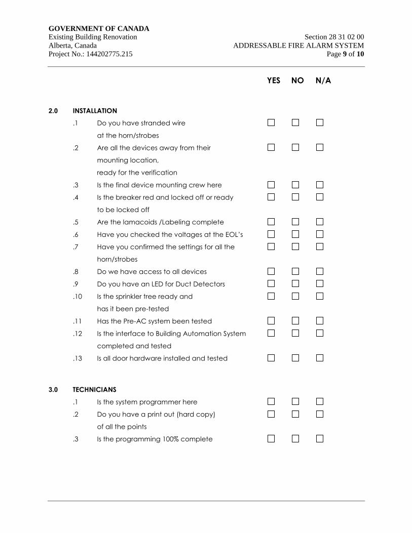
GOVERNMENT OF CANADA Existing Building Renovation Section 28 31 02 00
Alberta, Canada ADDRESSABLE FIRE ALARM SYSTEM
Project No.: 144202775.215 Page 9 of 10
YES NO N/A
2.0 INSTALLATION
.1 Do you have stranded wire
at the horn/strobes
.2 Are all the devices away from their
mounting location,
ready for the verification
.3 Is the final device mounting crew here
.4 Is the breaker red and locked off or ready
to be locked off
.5 Are the lamacoids /Labeling complete
.6 Have you checked the voltages at the EOL’s
.7 Have you confirmed the settings for all the
horn/strobes
.8 Do we have access to all devices
.9 Do you have an LED for Duct Detectors
.10 Is the sprinkler tree ready and
has it been pre-tested
.11 Has the Pre-AC system been tested
.12 Is the interface to Building Automation System
completed and tested
.13 Is all door hardware installed and tested
3.0 TECHNICIANS
.1 Is the system programmer here
.2 Do you have a print out (hard copy)
of all the points
.3 Is the programming 100% complete
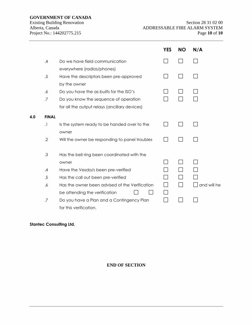
GOVERNMENT OF CANADA Existing Building Renovation Section 28 31 02 00
Alberta, Canada ADDRESSABLE FIRE ALARM SYSTEM
Project No.: 144202775.215 Page 10 of 10
YES NO N/A
.4 Do we have field communication
everywhere (radios/phones)
.5 Have the descriptors been pre-approved
by the owner
.6 Do you have the as-builts for the ISO’s
.7 Do you know the sequence of operation
for all the output relays (ancillary devices)
4.0 FINAL
.1 Is the system ready to be handed over to the
owner
.2 Will the owner be responding to panel troubles
.3 Has the bell ring been coordinated with the
owner
.4 Have the Vesda/s been pre-verified
.5 Has the call out been pre-verified
.6 Has the owner been advised of the Verification and will he
be attending the verification
.7 Do you have a Plan and a Contingency Plan
for this verification.
Stantec Consulting Ltd.
END OF SECTION