Embed Size (px)
Citation preview
Public Review Draft Whitewater River Region SWMP
April 2009
APPENDIX H
Whitewater River Region Water Quality Management Plan for Urban Runoff
WHITEWATER RIVER REGION
WATER QUALITY MANAGEMENT PLANFOR URBAN RUNOFF
April 2009
PUBLIC REVIEW DRAFT

Whitewater River Region WQMP Public Review Draft
April 2009 i
Table of Contents
1.0 Introduction.....................................................................................................................................1
2.0 Development Planning and Permitting Process ........................................................................2
2.1 Overview............................................................................................................................. 22.2 Conditions of Approval ...................................................................................................... 32.3 Implementation of WQMP Requirements .......................................................................... 5
3.0 Project-Specific WQMP Preparation .........................................................................................5
3.1 Project Description ............................................................................................................. 73.2 Site Characterization......................................................................................................... 103.3 Identify Pollutants of Concern.......................................................................................... 113.4 Identify Hydrologic Conditions of Concern ..................................................................... 123.5 BMP Selection .................................................................................................................. 14
3.5.1 Site Design and Treatment Control BMPs .............................................................173.5.2 Source Control BMPs.............................................................................................263.5.3 Equivalent Treatment Control Alternatives............................................................32
3.6 Operation and Maintenance .............................................................................................. 333.7 Funding ............................................................................................................................. 343.8 WQMP Certification......................................................................................................... 35
4.0 Regionally-Based Treatment Control .......................................................................................36
5.0 Changes in Site Development or Ownership ...........................................................................37
5.1 Changes in Site Development........................................................................................... 375.2 Changes in Site Ownership............................................................................................... 37
6.0 Waiver of Treatment Control BMP Requirements................................................................38
List of TablesTable 1. Permittee Departments Responsible for Conditions of Approval and Project-Specific WQMP Review .......................................................................................................................................................... 5Table 2. List of Sub-Watersheds/Receiving Waters in Whitewater River Watershed.................................. 8Table 3. Receiving Waters and Beneficial Uses ......................................................................................... 11Table 4. Summary of BMPs for Priority Development Projects ................................................................ 16Table 5. Treatment Control BMP Selection Matrix.................................................................................... 18Table 6. Permittees Requiring Onsite Retention of Stormwater................................................................ 20Table 7. Design Basis for Site Design and Treatment Control BMPs ........................................................ 23
List of FiguresFigure 1. Development Planning and Permitting Process............................................................................. 3Figure 2. Sub-Watershed and Receiving Waters Map.................................................................................. 9

Whitewater River Region WQMP Public Review Draft
April 2009 ii
List of ExhibitsA Project-Specific WQMP TemplateB General Categories of Pollutants of ConcernC Riverside County Whitewater River Region Stormwater Quality Best Management Practice Design
HandbookD Runoff Coefficients for Urban Soil TypesE. Typical Requirements for Common Maintenance MechanismsF. Sample Covenant and AgreementG. Glossary

Whitewater River Region WQMP Public Review Draft
April 2009 1
1.0 IntroductionThis Whitewater River Region Water Quality Management Plan (WQMP)1 has been developed to further address post-construction Urban Runoff from New Development and Redevelopment projects under the jurisdiction of the Permittees and is an appendix to Whitewater River Watershed Stormwater Management Plan (SWMP). Since 1996 the Permittees have addressed the potential post-construction impacts associated with Urban Runoff through Supplement A, New Development Guidelines. Supplement A, New Development Guidelines, was included as Appendix B to the 2001 Whitewater River Region SWMP and Appendix F to the 2006 Whitewater River Region SWMP. This Whitewater River Region WQMP replaces Supplement A, New Development Guidelines.
The Whitewater River Region WQMP is intended to provide guidelines for project-specific post-construction Best Management Practices (BMPs) and for regional and sub-regional Treatment Control BMPs. It addresses the management of Urban Runoff quantity and quality to help protect Receiving Waters. The WQMP identifies the BMPs, including criteria for Site Design and Treatment Control BMPs that may be applicable when considering any map or permit for which discretionary approval is sought. Examples may include tentative tract maps, parcel maps with land disturbing activity, discretionary grading permits where the Project is not part of a master plan of development, and conditional use permits. The Whitewater River Region WQMP includes tables and exhibits that are based upon current information regarding Permittee organizational structures; BMP design, technologies, and effectiveness; Receiving Waters; and Pollutants of Concern. Such information is dynamic and will be updated by thePermittees as appropriate.
Implementation of the Whitewater River Region WQMP will occur through the review and approval by the Permittee of a project-specific WQMP prepared by the project applicant. The project-specific WQMP will address management of Urban Runoff from a Project site, represented by a map or permit for which discretionary approval is sought from a Permittee. The primary objective of the WQMP, by addressing Site Design, Source Control, and Treatment Control BMPs applied on a project-specific and/or sub-regional or regional basis, is to ensure that the land use approval and permitting process of each Permittee will prevent or minimize the impact of Urban Runoff on Receiving Waters to the Maximum Extent Practicable (MEP).
The preparation, approval, and implementation of a project-specific WQMP is required for all discretionary New Development and Redevelopment projects submitted after June 15, 2009, that fall into one of the following Priority Development Project 2categories:
1. Single-family hillside residences that create 10,000 square feet or more of impervious area where the natural slope is 25% or greater;
2. Single-family hillside residences that create 10,000 square feet or more of impervious area where the natural slope is 10% or greater where erosive soil conditions are known;
3. Commercial and industrial developments of 100,000 square feet or more;
1 The State Water Resources Control Board and some of the Regional Water Quality Control Boards utilize the
term Standard Urban Stormwater Mitigation Plan (SUSMP) rather than Water Quality Management Plan (WQMP).
2 Section F.1.c.iv of the 2008 MS4 Permit (Colorado River Basin Regional Water Quality Control Board Order No. R7-2008.0001)
Whitewater River Region WQMP Public Review Draft
April 2009 2
4. Automotive repair shops [includes Standard Industrial Classification (SIC) codes 5013, 7532, 7533, 7534, 7537, 7538, and 7539];
5. Retail gasoline outlets disturbing greater than 5,000 square feet;
6. Restaurants disturbing greater than 5,000 square feet;
7. Home subdivisions with 10 or more housing units; and
8. Parking lots of 5,000 square feet or more or with 25 or more parking spaces and potentially exposed to Urban Runoff.
Since some projects will be subject to discretionary approval during the planning phase (land use entitlement) and ministerial approval for subsequent grading or building permits, project applicants may be required to submit a preliminary project-specific WQMP for discretionary project approval (land use entitlement). Project applicants shall be required to submit for Permittee review and approval a final project-specific WQMP that is in substantial conformance with the preliminary project-specific WQMP prior to the issuance of any building or grading permit. At its discretion, a Permittee may require a project-specific WQMP for Priority Development Projects submitted prior to June 15, 2009.
2.0 Development Planning and Permitting Process
2.1 Overview
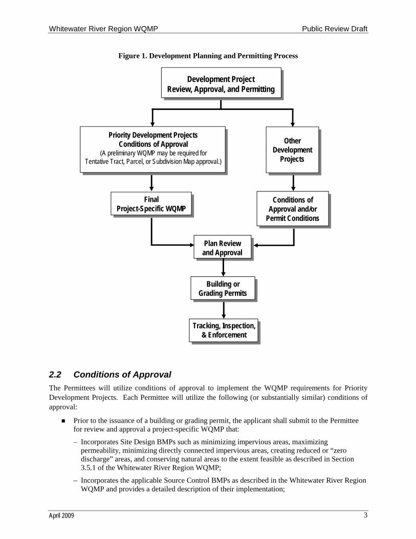
The objective of the Development Planning and Permitting Program is to ensure that controls are in place to prevent or minimize water quality impacts from New Development and Redevelopment Projects to the MEP. The development approval and permitting processes carries forth project-specific requirements in the form of conditions of approval, design criteria, tracking, inspection, and enforcement actions. Some projects may be subject to discretionary approval during land use entitlement and ministerial approval for subsequent permits. Such projects may be required to submit a preliminary project-specific WQMP during the land use entitlement process. Figure 1 is a flow diagram that generally depicts the development planning and permitting process.
Section 4 of the SWMP provides the overall framework for the planning, design, review, approval, and permitting of land use development to manage Urban Runoff for the protection of Receiving Waters. This WQMP provides guidelines for project-specific post-construction BMPs, as well as, alternatives for regional and sub-regional Treatment Control BMPs, but is only one component of the overall framework. Priority Development Projects will be conditioned to require the preparation, review, and approval of a project-specific WQMP. Other Development Projects, which are defined as New Development or Redevelopment projects that discharge into the MS4 and disturb an area of one acre or more, or disturb less than one acre, but are part of a larger common plan of development or sale3, will be required to incorporate a combination of Structural and Non-Structural Source Control BMPs, as applicable and feasible, into project plans through conditions of approval or building/grading permit conditions in accordance with Section 4.2.1 of the SWMP.
3 Section F.1.c.iii.1 of the 2008 MS4 Permit (Colorado River Basin Regional Water Quality Control Board Order
No. R7-2008.0001)
Whitewater River Region WQMP Public Review Draft
April 2009 3
Figure 1. Development Planning and Permitting Process
Development ProjectReview, Approval, and Permitting
OtherDevelopment
Projects
Priority Development ProjectsConditions of Approval
(A preliminary WQMP may be required forTentative Tract, Parcel, or Subdivision Map approval.)
FinalProject-Specific WQMP
Building or Grading Permits
Building or Grading Permits
Tracking, Inspection, & Enforcement
Conditions of Approval and/or
Permit Conditions
Plan Reviewand Approval
2.2 Conditions of Approval
The Permittees will utilize conditions of approval to implement the WQMP requirements for Priority Development Projects. Each Permittee will utilize the following (or substantially similar) conditions of approval:
Prior to the issuance of a building or grading permit, the applicant shall submit to the Permittee for review and approval a project-specific WQMP that:
– Incorporates Site Design BMPs such as minimizing impervious areas, maximizing permeability, minimizing directly connected impervious areas, creating reduced or “zero discharge” areas, and conserving natural areas to the extent feasible as described in Section 3.5.1 of the Whitewater River Region WQMP;
– Incorporates the applicable Source Control BMPs as described in the Whitewater River Region WQMP and provides a detailed description of their implementation;
Whitewater River Region WQMP Public Review Draft
April 2009 4
– Incorporates Treatment Control BMPs as described in the Whitewater River Region WQMP and provides information regarding design considerations;
– Describes the long-term operation and maintenance requirements for BMPs requiring long-term maintenance; and
– Describes the mechanism for funding the long-term operation and maintenance of the BMPs requiring long-term maintenance.
Prior to issuance of any building or grading permits, the property owner shall record a “Covenant and Agreement” with the County-Clerk Recorder or other instrument acceptable to the Permittee on a standardized form to inform future property owners of the requirement to implement the approved project-specific WQMP. Other alternative instruments for requiring implementation of the approved project-specific WQMP include: requiring the implementation of the project-specific WQMP in Home Owners Association or Property Owner Association Conditions, Covenants and Restrictions (CC&Rs); formation of Landscape, Lighting and Maintenance Districts, Assessment Districts or Community Service Areas responsible for implementing the project-specific WQMP; or equivalent may also be considered. Alternative instruments must be approved by the Permittee prior to the issuance of any building or grading permits.
Prior to the issuance of any grading or building permits for projects that will result in soil disturbance of one or more acres of land, the applicant shall demonstrate that coverage has been obtained under California’s General Permit for Stormwater Discharges Associated with Construction Activity or the General Permit for Stormwater Discharges Associated with Construction Activity from Small Linear Underground/Overhead Projects, as appropriate, by providing a copy of the Notice of Intent submitted to the SWRCB and a copy of the subsequent notification of the issuance of a Waste Discharge Identification (WDID) number or other proof of filing.
If the project will cause soil disturbance of one acre or more, the project must comply with either the General Permit for Stormwater Discharges Associated with Construction Activity or the General Permit for Stormwater Discharges Associated with Construction Activity from Small Linear Underground/Overhead Projects and shall prepare and implement a stormwater pollution prevention plan (SWPPP). Where applicable, the project applicant shall cause the approved final project-specific WQMP to be incorporated by reference or attached to the project’s SWPPP as the Post-Construction Management Plan. A copy of the up-to-date SWPPP shall be kept at the project site and be available for review upon request.
Prior to building or grading permit close-out or the issuance of a certificate of occupancy or certificate of use, the applicant shall:
– Demonstrate that all structural BMPs described in the project-specific WQMP have been constructed and installed in conformance with approved plans and specifications;
– Demonstrate that applicant is prepared to implement all non-structural BMPs described in the approved project-specific WQMP; and
– Demonstrate that an adequate number of copies of the approved project-specific WQMP are available for the future owners/occupants.
For industrial facilities subject to the General Permit for Stormwater Discharges Associated with Industrial Activity as defined by Standard Industrial Classification (SIC) code, prior to grading or building permit close-out and/or the issuance of a certificate of use or a certificate of occupancy, the applicant shall demonstrate that coverage has been obtained by providing a copy of the Notice of Intent submitted to the SWRCB and a copy of the notification of the issuance of a Waste Discharge Identification (WDID) Number or other proof of filing.
Whitewater River Region WQMP Public Review Draft
April 2009 5
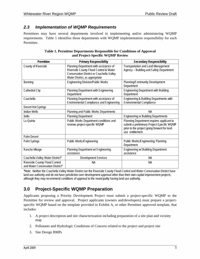
2.3 Implementation of WQMP Requirements
Permittees may have several departments involved in implementing and/or administering WQMP requirements. Table 1 identifies those departments with WQMP implementation responsibility for each Permittee.
Table 1. Permittee Departments Responsible for Conditions of Approvaland Project-Specific WQMP Review
Permittee Primary Responsibility Secondary ResponsibilityCounty of Riverside Planning Department with assistance of
Riverside County Flood Control & Water Conservation District or Coachella Valley Water District, as appropriate
Transportation and Land Management Agency – Building and Safety Department
Banning Engineering Division/Public Works Planning/Community Development Department
Cathedral City Planning Department with Engineering Department
Engineering Department with Building Department
Coachella Planning Department with assistance of Environmental Compliance and Engineering
Engineering & Building Departments with Environmental Compliance
Desert Hot SpringsIndian Wells Planning and Public Works Departments NAIndio Planning Department Engineering or Building DepartmentsLa Quinta Public Works Department conditions and
reviews project-specific WQMPPlanning Department requires applicant to submit a preliminary Project-Specific WQMP prior to the project going forward for land use entitlement
Palm DesertPalm Springs Public Works/Engineering Public Works/Engineering; Planning
DepartmentRancho Mirage Planning Department w/ Engineering
assistanceEngineering w/ Building Departmentassistance
Coachella Valley Water District* Development Services NARiverside County Flood Control and Water Conservation District*
NA NA
*Note: Neither the Coachella Valley Water District nor the Riverside County Flood Control and Water Conservation District have land use authority and do not have jurisdiction over development approval other than their own capital improvement projects, although they may recommend conditions of approval to the municipality having land use authority.
3.0 Project-Specific WQMP PreparationApplicants proposing a Priority Development Project must submit a project-specific WQMP to the Permittee for review and approval. Project applicants (owners and/developers) must prepare a project-specific WQMP based on the template provided in Exhibit A, or other Permittee approved template, that includes:
1. A project description and site characterization including preparation of a site plan and vicinity map
2. Pollutants and Hydrologic Conditions of Concern related to the project and project site
3. Site Design BMPs
Whitewater River Region WQMP Public Review Draft
April 2009 6
4. Source Control BMPs
5. Where applicable, project-specific Treatment Control BMPs or a regional, watershed approach; including basis for selection, sizing, and incorporation of Treatment Control BMPs (where used, a watershed or regional program must be identified)
6. An operation and maintenance requirements program, including responsible entities, for BMPs
7. Proposed funding source for operations and maintenance of BMPs. Where a public agency is identified as the funding source and responsible party for BMPs, a written agreement that states acceptance of these responsibilities by the public agency must be provided.
For Projects not participating in a regional or watershed-based Treatment Control BMP program, a preliminary or final project-specific WQMP must be prepared and submitted to the Permittee for review and approval in conjunction with considering any map or permit for which discretionary approval is sought. Where an applicant prepared a preliminary project-specific WQMP in obtaining discretionary project approval (land use entitlement), the applicant is required to submit for Permittee review and approval a final project-specific WQMP that is in substantial conformance with the preliminary project-specific WQMP prior to the issuance of any building or grading permit.
For Projects participating in regional or watershed-based Treatment Control BMP programs, the regional or watershed-based Treatment Control BMP program may be relied upon during the discretionary review process subject to a discussion of how the project will participate in the program. However, a preliminary project-specific WQMP shall be developed, submitted and approved by the Permittee concurrently with any map or permit for which discretionary approval is sought. The preliminary project-specific WQMP shall identify which pollutants and Hydrologic Conditions of Concern will be addressed by the regional or watershed-based Treatment Control BMP and any additional on-site Treatment Control BMPs that will be needed to address pollutants and Hydrologic Conditions of Concern not controlled by the regional or watershed-based facilities.
The level of detail in a preliminary project-specific WQMP submitted during the land use entitlement process will depend upon the level of detail known about the overall project design at the time project approval is sought. The preliminary project-specific WQMP must clearly identify the Permittee’s case number (tract number, use case number, design review number, etc.) for the project. The preliminary project-specific WQMP shall include a Site Plan (e.g., copy of the tentative map, use exhibit, preliminary precise grading plan, or other equivalent figure) identifying the major features of the proposed project. Locations of activities, storage areas, or other features that could expose Urban Runoff to pollutants must be clearly identified on the Site Plan (e.g., map, exhibit, or figure).
A final project-specific WQMP shall be submitted and approved by the Permittee prior to the issuance of any building or grading permit and the final project-specific WQMP shall be in substantial conformance with the preliminary WQMP submitted and approved by the Permittee during the land use entitlement process. The final project-specific WQMP must clearly identify the Permittee’s case number (tract number, use case number, design review number, etc.) for the project. The final project-specific WQMP shall include a Site Plan (e.g., the approved final map, use exhibit, or other equivalent figure or figures) identifying the major features of the proposed project. Locations of activities, storage areas, or other features that could expose Urban Runoff to pollutants and locations of BMPs must be clearly identified on the Site Plan (e.g., map, exhibit, or figure).
Whitewater River Region WQMP Public Review Draft
April 2009 7
3.1 Project Description
The project description shall completely and accurately describe in narrative form, and with supporting figures (maps or exhibits), where facilities will be located, what activities will be conducted and where, what kinds of materials will be used and/or stored, how and where materials will be delivered, and the types of wastes that will be generated. The following information shall be described, provided and/or addressed in the “Project Description” section of a project-specific WQMP:
The name(s), address(es), and phone number(s) of the project owner, project proponent and project-specific WQMP preparer.
The project’s site address, including APN number(s) and Thomas Brothers map page(s) and grids.
Planning Area/Community Name.
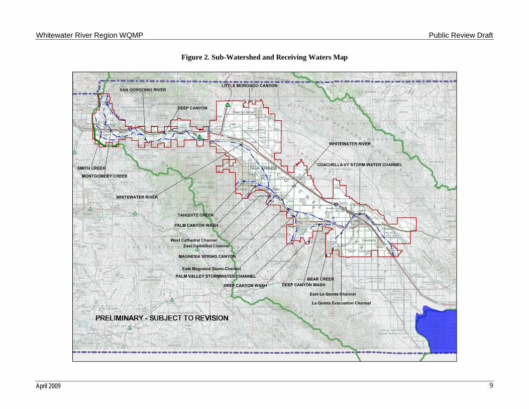
The sub-watershed in which the project is located, appropriately identified from the list of Receiving Waters in Table 2. A map showing the locations of these sub-watersheds and Receiving Waters is provided in Figure 2.
Project site size to the nearest 0.1 acre, and the pre-project and post-project quantity (square feet or acres) and percentage of pervious to impervious surface.
Standard Industrial Classification (SIC) code for commercial or industrial projects.
Identification of whether a Home Owners Association (HOA) or Property Owners Association (POA)4 will be formed.
The final project-specific WQMP shall include a copy of the final conditions of approval included as an appendix.
A copy of CC&Rs for the project, if applicable, included as an appendix.
A vicinity map showing the project site and surrounding planning areas in sufficient detail to allow project site to be plotted on a base map of the Permittee.
A site map (or maps) depicting the following project features:
– Number and type of structures and the intended use (buildings, tenant spaces, dwelling units, community facilities such as pools, recreation facilities, tot lots, etc.)
– Paved areas and the intended use (parking, outdoor work area, outdoor material storage area, sidewalks, patios, tennis courts, etc.)
– Landscaped areas
– Infrastructure (streets, storm drains, etc.) that will revert to public agency ownership and operation
– Location of existing and proposed drainage facilities (storm drains, channels, basins, etc), including catch basins and other inlets/outlet structures. Existing and proposed drainage facilities should be clearly differentiated.
– All proposed structural BMPs (source control and treatment control), their location, references to details, specifications, and product information
– Location(s) of Receiving Waters to which the project directly or indirectly discharges
4 As used herein, a Home Owners Association (HOA) or Property Owners Association (POA) means a nonprofit
corporation or unincorporated association created for the purpose of managing a common interest development [California Civil Code § 1351(a)].
Whitewater River Region WQMP Public Review Draft
April 2009 8
– Location of points where onsite (or tributary offsite) flows exit the project site
– Delineation of proposed tributary area boundaries, including tributary offsite areas, for each location where flow exits the property. Each tributary area should be clearly denoted (A, B, C, etc.)
– Pre-project and post-project topography
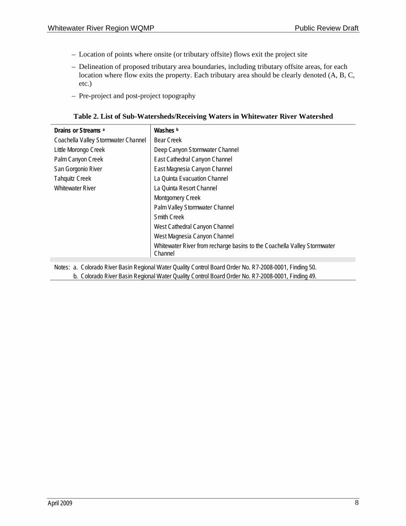
Table 2. List of Sub-Watersheds/Receiving Waters in Whitewater River Watershed
Drains or Streams a Washes b
Coachella Valley Stormwater Channel Bear Creek
Little Morongo Creek Deep Canyon Stormwater Channel
Palm Canyon Creek East Cathedral Canyon Channel
San Gorgonio River East Magnesia Canyon Channel
Tahquitz Creek La Quinta Evacuation Channel
Whitewater River La Quinta Resort Channel
Montgomery Creek
Palm Valley Stormwater Channel
Smith Creek
West Cathedral Canyon Channel
West Magnesia Canyon Channel
Whitewater River from recharge basins to the Coachella Valley Stormwater Channel
Notes: a. Colorado River Basin Regional Water Quality Control Board Order No. R7-2008-0001, Finding 50.b. Colorado River Basin Regional Water Quality Control Board Order No. R7-2008-0001, Finding 49.
Whitewater River Region WQMP Public Review Draft
April 2009 9
Figure 2. Sub-Watershed and Receiving Waters Map
Whitewater River Region WQMP Public Review Draft
April 2009 10
3.2 Site Characterization
The following information shall be addressed in the “Site Characterization” section of a project-specific WQMP:
Current and proposed zoning or land use designation
Current actual use of project site (undeveloped, previously developed but vacant, existing structures, etc.)
Name(s) of Receiving Water(s) to which the project site discharges directly or indirectly
Identification of any Clean Water Act §303(d) listed impairments or Total Maximum Daily Loads (TMDLs) for the identified Receiving Waters.5
Designated beneficial uses for Receiving Waters to which the project site discharges, appropriately identified from Table 3, and including proximity to Receiving Waters with a Rare,Threatened, or Endangered Species (“RARE”) beneficial use.
If a Phase 1 environmental site assessment has been prepared for the project site, a summary of the site remediation conducted (or to be conducted) and any site use restrictions.
If infiltration BMPs are proposed, a soils report should be included as an appendix identifying the soil type(s), infiltration capacity of the soils, and depth to groundwater.
5 The most recent CWA Section 303(d) List of Water Quality Limited Segments, adopted TMDLs, and TMDLs
pending resolution can be found at http://www.waterboards.ca.gov/coloradoriver/water_issues/programs/tmdl/
Whitewater River Region WQMP Public Review Draft
April 2009 11
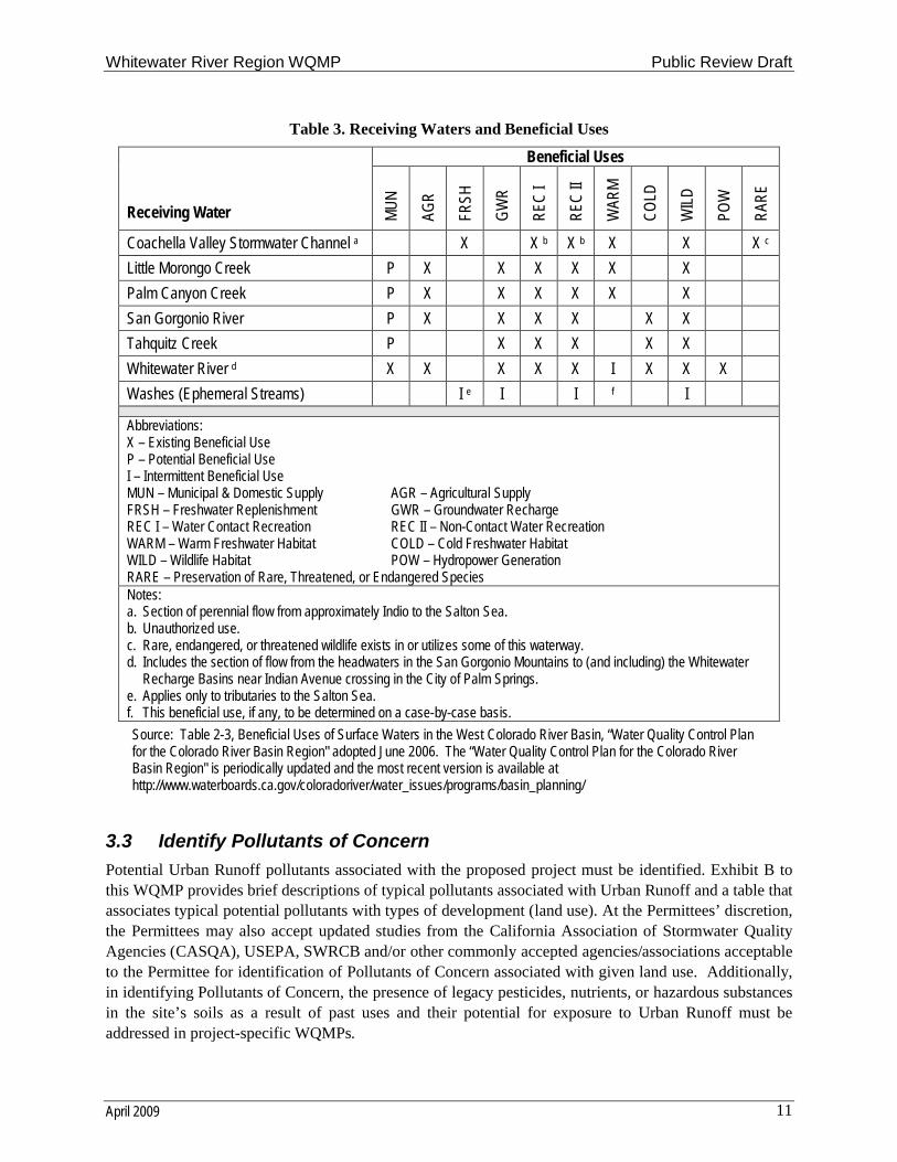
Table 3. Receiving Waters and Beneficial Uses
Beneficial Uses
Receiving Water MU
N
AGR
FRSH
GW
R
REC
I
REC
II
WAR
M
CO
LD
WIL
D
POW
RAR
E
Coachella Valley Stormwater Channel a X X b X b X X X c
Little Morongo Creek P X X X X X X
Palm Canyon Creek P X X X X X X
San Gorgonio River P X X X X X X
Tahquitz Creek P X X X X X
Whitewater River d X X X X X I X X X
Washes (Ephemeral Streams) I e I I f I
Abbreviations:X – Existing Beneficial UseP – Potential Beneficial UseI – Intermittent Beneficial UseMUN – Municipal & Domestic Supply AGR – Agricultural SupplyFRSH – Freshwater Replenishment GWR – Groundwater RechargeREC I – Water Contact Recreation REC II – Non-Contact Water RecreationWARM – Warm Freshwater Habitat COLD – Cold Freshwater HabitatWILD – Wildlife Habitat POW – Hydropower GenerationRARE – Preservation of Rare, Threatened, or Endangered SpeciesNotes:a. Section of perennial flow from approximately Indio to the Salton Sea.b. Unauthorized use.c. Rare, endangered, or threatened wildlife exists in or utilizes some of this waterway. d. Includes the section of flow from the headwaters in the San Gorgonio Mountains to (and including) the Whitewater
Recharge Basins near Indian Avenue crossing in the City of Palm Springs.e. Applies only to tributaries to the Salton Sea.f. This beneficial use, if any, to be determined on a case-by-case basis.
Source: Table 2-3, Beneficial Uses of Surface Waters in the West Colorado River Basin, “Water Quality Control Plan for the Colorado River Basin Region" adopted June 2006. The “Water Quality Control Plan for the Colorado River Basin Region" is periodically updated and the most recent version is available at http://www.waterboards.ca.gov/coloradoriver/water_issues/programs/basin_planning/
3.3 Identify Pollutants of Concern
Potential Urban Runoff pollutants associated with the proposed project must be identified. Exhibit B to this WQMP provides brief descriptions of typical pollutants associated with Urban Runoff and a table that associates typical potential pollutants with types of development (land use). At the Permittees’ discretion, the Permittees may also accept updated studies from the California Association of Stormwater Quality Agencies (CASQA), USEPA, SWRCB and/or other commonly accepted agencies/associations acceptable to the Permittee for identification of Pollutants of Concern associated with given land use. Additionally, in identifying Pollutants of Concern, the presence of legacy pesticides, nutrients, or hazardous substances in the site’s soils as a result of past uses and their potential for exposure to Urban Runoff must be addressed in project-specific WQMPs.
Whitewater River Region WQMP Public Review Draft
April 2009 12
The Permittees should also require specific pollutants commonly associated with Urban Runoff to be considered as Pollutants of Concern for a specific project based on known problems, such as known exceedances of water quality standards or Clean Water Act §303(d) impairments in the Receiving Waters and suspected association with that land use. The list of potential Urban Runoff pollutants identified for the project must be compared with the pollutants identified as causing an impairment of Receiving Waters, if any. To identify pollutants impairing proximate Receiving Waters, each project proponent preparing a project-specific WQMP shall, at a minimum, do the following:
a) For each of the proposed project discharge points, identify the proximate Receiving Water(s)for each discharge point.
b) For each identified Receiving Water included in the most recent Clean Water Act §303(d) list of impaired water bodies, list all pollutants for which the proximate Receiving Water(s) isimpaired.
c) Compare the list of pollutants for which the proximate Receiving Water(s) is impaired with the potential pollutants of concern generated by the project.
The combination of Site Design BMPs, Source Control BMPs, and Treatment Control BMPs incorporated into the project plans must address the potential Pollutants of Concern identified for the project. Further, the selection of a Treatment Control BMP (or BMPs) for the project must specifically consider the effectiveness of the Treatment Control BMP for pollutants identified as causing an impairment of Receiving Waters to which the project will discharge Urban Runoff. See Section 3.5, BMP Selection, for additional guidance in selecting appropriate BMPs to address Pollutants of Concern.
3.4 Identify Hydrologic Conditions of Concern
Impacts to the hydrologic regime resulting from New Development or Redevelopment Projects may include increased runoff volume and velocity; reduced infiltration; increased flow frequency, duration, and peaks; faster time to reach peak flow; and water quality degradation. Under certain circumstances, changes due to land development could also result in the reduction in the amount of available sediment for transport, which may lead to storm flows achieving sediment-carrying capacity by eroding the downstream channel. Such changes have the potential to permanently impact downstream channels and habitat integrity.
The MS4 Permit requires that developments minimize changes to hydrology to ensure that post-development runoff rates and velocities from a site do not increase the potential for downstream erosionor sedimentation or adversely impact stream habitat. Urban Runoff and associated impacts may be reduced by minimizing impervious surfaces and incorporating other site-design concepts that replicate or reduce impacts to the pre-development condition. The goal of these site design techniques is to achieve post development runoff flow rates, volumes, velocities and durations that do not exceed the pre-development condition, where an increase will result in greater potential for downstream erosion, and prevent significant adverse impacts to stream habitat during the 2-year and 10-year, 24-hour rainfall event. More information on maximizing onsite infiltration and minimizing impacts to stream channels can be found in Start at the Source (Bay Area Stormwater Management Agencies Association, 1999) and Low Impact Development Design Strategies, An Integrated Design Approach (Prince George’s County, Maryland; Department of Environmental Resources, 1999).
Whitewater River Region WQMP Public Review Draft
April 2009 13
A project-specific WQMP must address the issue of Hydrologic Conditions of Concern unless one of the following conditions are met:
Condition A: Runoff from the Project is discharged directly to a publicly-owned, operated and maintained MS4; the discharge is in full compliance with Permittee requirements for connections and discharges to the MS4 (including both quality and quantity requirements); the discharge would not significantly impact stream habitat in proximate Receiving Waters; and the discharge is authorized by the Permittee.
Condition B: The project disturbs less than 1 acre and is not part of a larger common plan of development that exceeds 1 acre of disturbance. The disturbed area calculation must include all disturbances associated with larger common plans of development.
Condition C: The project’s runoff flow rate, volume, velocity and duration for the post-development condition do not exceed the pre-development condition for the 2-year, 24-hour and 10-year, 24-hour rainfall events. This condition can be achieved by minimizing impervious area on a site and incorporating other site-design concepts that mimic pre-development conditions. This condition must be substantiated by hydrologic modeling methods acceptable to the Permittee.
For all other Priority Development Projects, the project-specific WQMP shall demonstrate that discharge flow rates, velocities, durations, and volumes from a 2-year and 10-year, 24-hour rainfall event will not significantly impact downstream erosion or stream habitat. The project applicant shall provide sufficient information to demonstrate to the Permittee that the project will not cause significant adverse impacts, or has mitigated significant impacts to downstream erosion or stream habitat.
To comply with this requirement the project applicant must include an evaluation of potential of the project to cause a significant increase in downstream erosion compared to the pre-development condition and/or cause significant adverse impacts to stream habitat. Project applicants must consider the hydrology of the entire tributary watershed. Watershed plans, drainage area master plans, or other planning documents should be reviewed to the extent available, to identify the BMP requirements necessary to address cumulative impacts from projects in the subarea of the watershed. Project applicants proposing new developments that fall into Category 2 (commercial and industrial developments of 100,000 square foot or more) or Category 6 (home subdivisions with 10 or more housing units) of the Priority Development categories will be required to submit to the Permittee a drainage study report prepared by a registered Civil Engineer in the State of California, with experience in water resources management. Other new development or redevelopment projects may be required to submit a detailed drainage study depending on specific site conditions. Such a drainage study must evaluate the impacts of the project on downstream channel reaches impacted during a 2-year, 24-hour and 10-year, 24-hour rainfall event. A drainage study report shall also consider the project’s location (from the larger watershed perspective), topography, soil and vegetation conditions, percent impervious area, natural and infrastructure drainage features, and any other relevant hydrologic and environmental factors to be protected. A field reconnaissance to evaluate natural downstream reaches and/or areas containing sensitive habitat may be required to assess undercutting erosion, slope/bank stability, vegetative stress, and susceptibility to other adverse hydrologic impacts from the project.
Whitewater River Region WQMP Public Review Draft
April 2009 14
If adverse hydrologic impacts are identified and they are not fully mitigated by the implementation of Site Design BMP concepts, then the project proponent shall, based upon consultation with the Permittee, use one of the following methodologies to address identified adverse impacts:
Methodology A
Project applicant shall design a detention basin capable of all of the following:
1. Releasing the post-development 2-year and 10-year, 24-hour volume at flow rates less than or equal to the pre-development 2-year and 10 year, 24-hour peak flow rates, respectively.
2. Passing the 100-year storm event without damage to the facility.
3. Controlling outlet velocities such that downstream erosion and habitat loss is minimized.
The basin may also function as a water quality extended detention basin, or serve other multi-use functions, with the approval of the Permittee.
Methodology B
Any method acceptable to the Permittee that:
1. Implements Site Design, Source Control, Treatment Control BMPs and/or other measures capable of mitigating the assessed hydrologic impacts. The method must be supported by hydrologic modeling or other sufficient documentation. Sufficient documentation could include reference to EPA, CASQA, SWRCB and/or other approved studies supporting the use of the method.
2. Ensures that the project will be consistent with any approved master plans of drainage or analogous plans or programs.
Hydrologic Condition of Concern BMPs should be designed in accordance with local vector control regulations and requirements. If a particular BMP does not meet vector control requirements, other BMPs should be considered. However, when the Permittee determines that a detention basin is the most effective way to address Hydrologic Conditions of Concern, the Permittee may approve minor deviations from the design criteria specified in this section to ensure that local vector control requirements are not violated (i.e., 72-hour maximum drain time from a basin full condition).
3.5 BMP Selection
BMPs shall be incorporated into the project-specific WQMP to minimize the impact from the Pollutants of Concern and Hydrologic Conditions of Concern identified for the project. Where Pollutants of Concerninclude pollutants that are listed as causing or contributing to impairments of Receiving Waters, BMPs must be selected so that the project does not cause or contribute to an exceedance of water quality objectives. Strategies to minimize the Pollutants of Concern in runoff from the project site and minimize hydrologic impact include Site Design BMPs, Source Control BMPs, and Treatment Control BMPs.
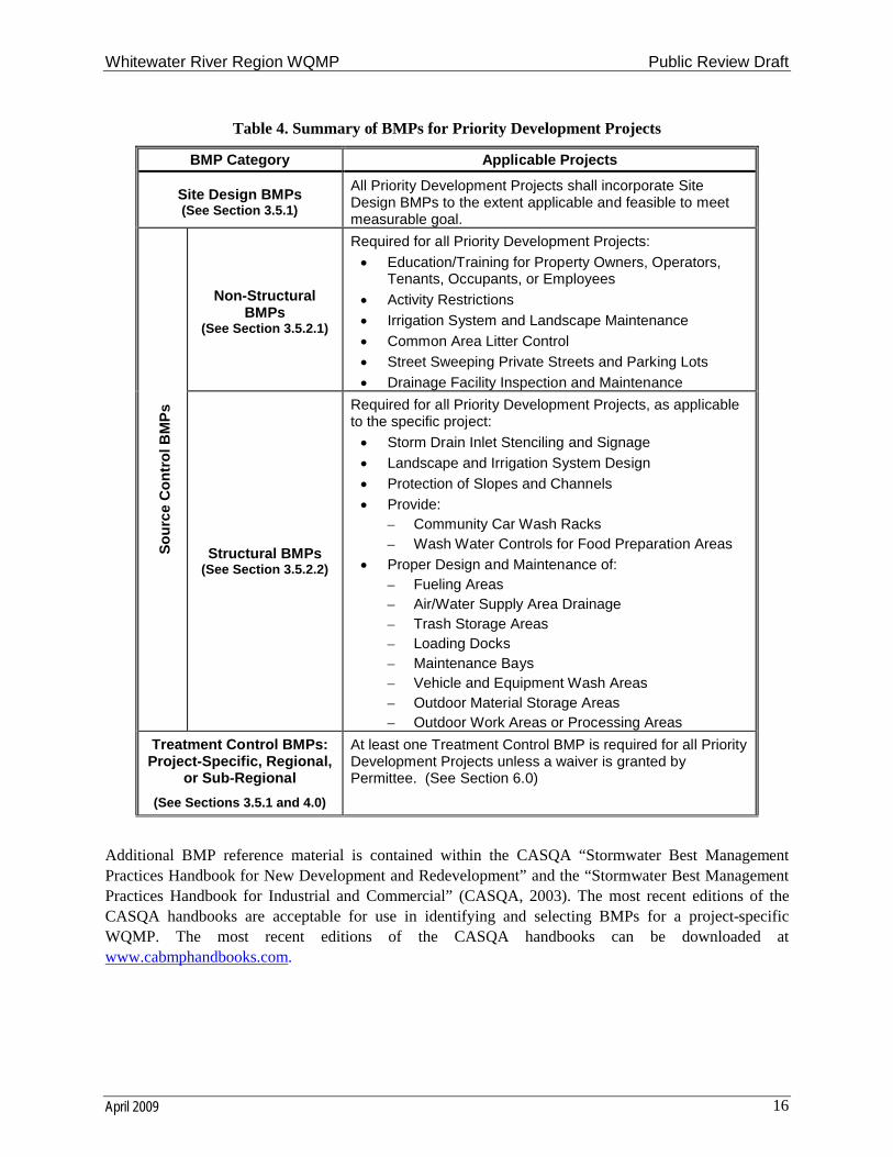
Site Design BMPs, Source Control BMPs, and Treatment Control BMPs most effectively protect water quality when used in combination. Site Design may be implemented to a level that significantly reduces the size or extent to which Treatment Control BMPs need to be implemented. BMPs should be located as close to the pollutant source as appropriate and economically/technologically feasible, and before Urban Runoff is discharged into Receiving Waters. Project applicants should also incorporate vector control requirements into the selection and design of Site Design, Source Control, and Treatment Control BMPs. A summary of the BMP requirements for Priority Development Projects is shown in Table 4.

Whitewater River Region WQMP Public Review Draft
April 2009 15
Site Design BMPs aim to incorporate site features such as vegetation and porous surfaces to reduce and control post-development runoff rates. Because Site Design BMPs reduce runoff, incorporating them into project design plans minimizes the:
transport mechanism (runoff) for moving pollutants off site,
difference between pre- and post-development hydrology thereby reducing changes in flow regime, and
size of necessary Treatment Control BMPs to treat Pollutants of Concern in Urban Runoff prior to discharge from the site or at regional facilities.
Source Control BMPs reduce the potential for Urban Runoff and pollutants from coming into contact with one another. Source Control BMPs are defined as any administrative action, design of a structural facility, usage of alternative materials, and operation, maintenance, and inspection procedures that eliminate or reduce Urban Runoff pollution. Each project is required to implement appropriate Source Control BMPs.
Treatment Control BMPs are defined as any engineered system designed and constructed to treat the adverse impacts of Urban Runoff pollution. These BMPs may remove Pollutants of Concern by filtration, media absorption, or other physical, biological, or chemical processes. It should be noted that where the project proponent believes that design criteria adequately addresses Pollutants of Concern and Treatment Controls are not needed, a request for a waiver must be submitted to and approved by the Permittee.
Whitewater River Region WQMP Public Review Draft
April 2009 16
Table 4. Summary of BMPs for Priority Development Projects
BMP Category Applicable Projects
Site Design BMPs(See Section 3.5.1)
All Priority Development Projects shall incorporate Site Design BMPs to the extent applicable and feasible to meet measurable goal.
Non-Structural BMPs
(See Section 3.5.2.1)
Required for all Priority Development Projects:
Education/Training for Property Owners, Operators, Tenants, Occupants, or Employees
Activity Restrictions
Irrigation System and Landscape Maintenance
Common Area Litter Control
Street Sweeping Private Streets and Parking Lots
Drainage Facility Inspection and Maintenance
So
urc
e C
on
tro
l BM
Ps
Structural BMPs(See Section 3.5.2.2)
Required for all Priority Development Projects, as applicable to the specific project:
Storm Drain Inlet Stenciling and Signage
Landscape and Irrigation System Design
Protection of Slopes and Channels
Provide: – Community Car Wash Racks– Wash Water Controls for Food Preparation Areas
Proper Design and Maintenance of:– Fueling Areas– Air/Water Supply Area Drainage– Trash Storage Areas– Loading Docks– Maintenance Bays– Vehicle and Equipment Wash Areas– Outdoor Material Storage Areas– Outdoor Work Areas or Processing Areas
Treatment Control BMPs:Project-Specific, Regional,
or Sub-Regional
(See Sections 3.5.1 and 4.0)
At least one Treatment Control BMP is required for all Priority Development Projects unless a waiver is granted by Permittee. (See Section 6.0)
Additional BMP reference material is contained within the CASQA “Stormwater Best Management Practices Handbook for New Development and Redevelopment” and the “Stormwater Best Management Practices Handbook for Industrial and Commercial” (CASQA, 2003). The most recent editions of the CASQA handbooks are acceptable for use in identifying and selecting BMPs for a project-specific WQMP. The most recent editions of the CASQA handbooks can be downloaded at www.cabmphandbooks.com.
Whitewater River Region WQMP Public Review Draft
April 2009 17
3.5.1 Site Design and Treatment Control BMPsSection F.1.c.v.2 of the MS4 Permit states, “Unless infeasible, the following Site Design BMPs are required and must be implemented in the site layout during the subdivision design and approval process,consistent with applicable General Plan and Local Area Plan policies:
a. Minimize Urban Runoff, Minimize Impervious Footprint, and Conserve Natural Areas, and
b. Minimize Directly Connected Impervious Area.”
Site Design BMPs are intended to create a hydrologically functional project design that attempts to mimic the natural hydrologic regime. Mimicking a site’s natural hydrologic regime can be pursued by:
Reducing imperviousness, conserving natural resources and areas, maintaining and using natural drainage courses in the MS4, and minimizing clearing and grading.
Providing runoff storage measures dispersed uniformly throughout a site’s landscape with the use of a variety of detention, retention, and runoff practices.
Implementing on-lot hydrologically functional landscape design and management practices.
These same practices, because they reduce the volume and usually the rate of runoff, also have the benefit of reducing the amount of stormwater that must be treated before being discharged or to be treated in regional facilities. These design principles offer an innovative approach to urban stormwatermanagement by uniformly or strategically integrating stormwater controls throughout the urban landscape. Resources for applying these principles include Start at the Source (Bay Area StormwaterManagement Agencies Association, 1999)6, and Low Impact Development Design Strategies, An Integrated Design Approach (Prince George’s County, Maryland; Department of Environmental Resources, 1999)7.
The Treatment Control BMP requirements specified in Section F.1.c.v.4 of the 2008 MS4 Permit shall be addressed using Site Design BMPs to the full extent feasible. Site Design BMPs function by infiltration, retention, reuse, evapotranspiration, biofiltration and/or bioretention and shall be designed to manage runoff consistent with the design sizing requirements, QBMP and/or VBMP, described in Sections Error! Reference source not found. and Error! Reference source not found., respectively. Where Site Design BMPs are infeasible, projects must incorporate other types of Treatment Control BMPs to meet the design criteria of QBMP and/or VBMP. Site Design and Treatment Control BMPs must address identified Pollutants of Concern and Hydrologic Conditions of Concern. Treatment Control BMPs may also be provided offsite or through a regionally-based Treatment Control BMP (see Section 4.0). Alternatives to onsite Site Design or Treatment Control BMPs are discussed in Sections 3.5.3 and 4, while waivers of Treatment Control BMP requirements are discussed in Section 6.
Table 5 summarizes expected performance of some common Site Design and Treatment Control BMPs in addressing various Pollutants of Concern. It should be noted that, at the discretion of the Permittee, updated studies from CASQA, EPA, SWRCB and/or other agencies/associations acceptable to the Permittee for determination of BMP pollutant removal efficiency may be allowed. For identified Pollutants of Concern that are causing impairments in receiving waters, the project-specific WQMP shall incorporate one or more BMPs of at least medium effectiveness in reducing those pollutants. For more specific information on the pollutant removal capabilities of various BMPs, refer to the CASQA “Stormwater Best Management Practices Handbook for New Development and Redevelopment”
6 http://www.oaklandpw.com/creeks/bmps.html7 http://www.epa.gov/owow/nps/lid/lidnatl.pdf

Whitewater River Region WQMP Public Review Draft
April 2009 18
(CASQA, 2003). Subsequent sections of this WQMP provide guidance for determining the flow (Section 3.5.1.7) or volume (Section 3.5.1.9) of runoff from a project to be treated via Site Design BMPs, or where Site Design BMPs are shown infeasible, via Treatment Control BMPs. The Riverside County Whitewater River Region Stormwater Quality Best Management Practice Design Handbook, which is included as Exhibit C, provides more detailed guidance.
Table 5. Treatment Control BMP Selection Matrix (1)
(Excerpted, with minor revision, from the Orange County Water Quality Management Plan dated September 26, 2003
and the San Bernardino Water Quality Management Plan dated April 14, 2004)
Pollutant of Concern Biofilters (2)DetentionBasins (3)
InfiltrationBMPs (4)
Wet Pondsor
Wetlands (5)Filtration
Systems (6)
WaterQualityInlets
HydrodynamicSeparator
Systems (7)
Manufacturedor Proprietary
Devices (8)
Sediment/Turbidity H/M M H/M H/M H/M L H/M(L for Turbidity)
U
Nutrients L M H/M H/M L/M L L U
Organic Compounds U U U U H/M L L U
Trash & Debris L M U U H/M M H/M U
Oxygen Demanding Substances
L M H/M H/M H/M L L U
Bacteria & Viruses U U H/M U H/M L L U
Oil & Grease H/M M U U H/M M L/M U
Pesticides(non-soil bound)
U U U U U L L U
Metals H/M M H H H L L U
Abbreviations:L: Low removal efficiency H/M: High or medium removal efficiency U: Unknown removal efficiency
Notes:(1) Periodic performance assessment and updating of the guidance provided by this table may be necessary.
(2) Includes grass swales, grass strips, wetland vegetation swales, and bioretention.
(3) Includes extended/dry detention basins with grass lining and extended/dry detention basins with impervious lining. Effectiveness based upon minimum 36-48-hour drawdown time.
(4) Includes infiltration basins, infiltration trenches, and porous pavements.
(5) Includes permanent pool wet ponds and constructed wetlands.
(6) Includes sand filters and media filters.
(7) Also known as hydrodynamic devices, baffle boxes, swirl concentrators, or cyclone separators.
(8) Includes proprietary stormwater treatment devices as listed in the CASQA Stormwater Best Management Practices Handbooks, other stormwater treatment BMPs not specifically listed in this WQMP, or newly developed/emerging stormwater treatment technologies.

Whitewater River Region WQMP Public Review Draft
April 2009 19
If a BMP selected for the project functions by infiltration, the BMP shall not violate the requirements set forth in 40 CFR 144 for Class V Injection Wells8 or any potential local infiltration requirements. For purposes of identifying local infiltration requirements, the Permittee will assist project applicants in identifying groundwater management agencies that may have established such requirements. In addition, BMPs that allow infiltration:
Must be at least 500 feet horizontally from any water supply well unless it can be shown that well construction and site geology will provide adequate protection for the domestic water well in which case the minimum distance will be provided on a case-by-case basis;
Must be at least 10 feet vertically above the historic high groundwater mark; and
Shall not cause a nuisance, including odor, vectors or pollution as defined in Water Code Section 13050.9
An additional resource for the appropriate siting of infiltration BMPs includes Caltrans Report No. CTSW-RT-03-025, Infiltration Basin Site Selection Study (June 2003)10.
The obligation to install Site Design and Treatment Control BMPs at project site is met if, for a common scheme of development, BMPs are constructed with the requisite capacity to serve the entire common scheme, even if certain phases of the common scheme may not have BMP capacity located on that phase. BMP capacity must be functional prior to the issuance of occupancy permits, or certificates of use (or equivalent), if no occupancy permits are issued.
Measurable Goal for Site Design BMPs
To the extent feasible, Priority Development Projects shall utilize the following site design concepts and incorporate Site Design BMPs into project plans to manage runoff produced by VBMP (the flow-based BMP design criteria) or QBMP (the volume-based BMP design criteria) as discussed in Sections 3.5.1.7 and3.5.1.9, respectively:
1. Site design measures that minimize the volume of runoff produced
2. Site design measures that promote onsite infiltration of precipitation and runoff
3. Site design measures that provide retention and storage for reuse
4. Site design measures that utilize vegetation and/or engineered soils for evapotranspiration and bioretention
3.5.1.1 Required On-Site Retention of Urban Runoff
As shown in Table 6, some Permittees require developments within their jurisdiction to retain Urban Runoff on site unless located adjacent to an existing MS4 facility. Where a project is required by the Permittee to retain and infiltrate Urban Runoff on site at a level equivalent to the Volumetric or Flow-Based Treatment Control BMP design criteria specified in the MS4 Permit (Section F.1.c.v.4), additional Site Design BMPs are not required.
8 http://frwebgate.access.gpo.gov/cgi-bin/multidb.cgi9 http://www.leginfo.ca.gov/cgi-bin/displaycode?section=wat&group=13001-14000&file=13050-1305110 http://www.dot.ca.gov/hq/env/stormwater/special/newsetup/_pdfs/new_technology/CTSW-RT-03-
025/IFB_Final_Report.pdf

Whitewater River Region WQMP Public Review Draft
April 2009 20
Table 6. Permittees Requiring Onsite Retention of Stormwater
Permittee Ordinance Requirement
Cathedral City Municipal Code – Title 8 § 8.24.070
A. Except as noted below, development of all land within the city must include provisions for the management of stormwater runoff from the property which is to be developed. This management shall consist of constructing stormwater storage facilities, which includes detention basins. As a minimum, all development will make provisions to store runoff from rainfall events up to and including the one-hundred-year, three-hour duration event. If a suitable outlet for a detention basin is not available, or if engineering analysis indicates that available outlet systems would be overtaxed by detention basin outflow, a retention basin shall be constructed in lieu of a detention basin.
B. The requirement for construction of a detention basin or a retention basin may be waived in the following cases:
1. The runoff has been included in a storage facility at another location. This may include storage facilities proposed as part of the Cathedral City Storm Drain Master Plan;
2. An application for a building permit to construct a single-family residential structure;
3. Development which will drain directly into a floodway or watercourse drainage channel which has been determined by the project review manager, using engineering analyses provided by the development, to have the capacity and be constructed to handle the additional runoff flow without increasing the potential for flood damage on any other downstream property.
4. Development of a parcel under one-half acre in an area where it can be demonstrated by engineering analyses that no significant increase in the potential for flood damage will be created by the development.
Indio Code of Ordinances – Title XV: Land Usage, §162.140
Properties of one acre or greater in size shall be designed to retain the 100-year, 24-hour, duration storm on site. Such properties shall retain this duration storm on site or provide a drainage system to convey the drainage to an acceptable retention site as determined by the Director of Public Works. Such a drainage system shall include a provision to fully address disposal of nuisance water to the satisfaction of the Director of Public Works.
La Quinta Municipal Code – Title 13 §13.24.120
D. Stormwater runoff produced over the peak twenty-four-hour period of a one-hundred-year storm shall be retained on site unless waived by the city engineer. Engineering Bulletin #06-16 sets Hydrology and Hydraulic Report Criteria for Storm Drainage Systems.
Palm Desert Municipal Code – Title 26 § 26.49.060
Developments of ten gross acres or more shall provide sufficient on-site stormwater retention and/or retardation so as to limit peak runoff during a storm having twenty-five-year intensity to a rate no greater than that which would have otherwise occurred under undeveloped conditions.
Palm Springs Municipal Code 9.60.030 (18) & (19)(A)
(18)The subdivider shall install storm sewer conduits, structures, and appurtenances when required, in accordance with the master plan of flood control and drainage or by city council direction.
(19)(A) The design of lots shall be in accordance with the zoning ordinance, adopted general plans, specific plans and with city policy.
Rancho Mirage Municipal Code – Title 15 §15.64.140
Properties of one acre or greater in size located northerly of the Whitewater River Channel shall be designed to retain the one-hundred-year, twenty-four-hour, duration storm on site. Other properties shall retain this duration storm on site or provide a drainage system to convey the drainage to an acceptable disposal site as determined by the city engineer.

Whitewater River Region WQMP Public Review Draft
April 2009 21
3.5.1.2 Site Design Concept 1: Minimize the Volume of Runoff Produced
Site Design BMPs that minimize the volume of runoff produced, such as conserving natural areas andminimizing the impervious footprint must be incorporated to the extent feasible during the site planning and approval process consistent with General Plan policies, other development standards and regulations,and with any Site Design BMPs included in an applicable regional or watershed program. Examples include:
Conserve natural areas:
– Concentrate or cluster development on the least environmentally sensitive portions of a site while leaving the remaining land in a natural, undisturbed condition.
– Where applicable, reflect the goals of the Multi-Species Habitat Conservation Plan or other natural resource plans in the project plans in order to preserve sensitive portions of the site, which includes but is not limited to, areas necessary to maintain the viability of wildlife corridors, habitat areas for sensitive, threatened or endangered, and all wetlands, coastal scrub, and other upland communities.
– Natural drainage features and natural depressional storage areas on the site are preserved
Maximize canopy interception and water conservation by preserving existing native trees and shrubs, and planting additional native or drought tolerant trees and large shrubs.
Use natural drainage systems.
Increase the building floor area ratio (i.e., number of stories above or below ground)
Construct streets, sidewalks and parking lot aisles to the minimum widths necessary, provided that public safety and a walkable environment for pedestrians are not compromised.11
Reduce widths of streets where off-street parking is available.12
Design driveways with shared access, flared (single lane at street), or wheel strips (paving only under tires).
Minimize the use of impervious surfaces, such as decorative concrete, in the landscape design.
Other comparable and equally effective site design concepts as approved by the Permittee.
3.5.1.3 Site Design Concept 2: Promote Onsite Infiltration of Precipitation and Runoff
Site Design BMPs to promote onsite infiltration of precipitation and runoff must be incorporated to the extent feasible during the site planning and approval process consistent with General Plan policies, other development standards and regulations, and with any Site Design BMPs included in an applicable regional or watershed program. Examples include:
Minimize Directly Connected Impervious Areas (DCIAs):
– Residential and commercial sites must be designed to contain and infiltrate roof runoff, or direct roof runoff to vegetative swales or buffer areas.
– Drain impervious sidewalks, walkways, trails, and patios into adjacent landscaping.
– Incorporate landscaped buffer areas between sidewalks and streets. 11 Sidewalk widths must still comply with Americans with Disabilities Act regulations and other life safety
requirements.12 However, street widths must still comply with life safety requirements for fire and emergency vehicle access in
addition to waste collection and facility maintenance needs.

Whitewater River Region WQMP Public Review Draft
April 2009 22
– Uncovered temporary or guest parking on residential lots may be paved with a permeable surface, or designed to drain into landscaping prior to discharging to the MS4.
– Use rural swale system: street sheet flows to vegetated swale or gravel shoulder, curbs used at street corners, and culverts used under driveways and street crossings.
– Use urban curb/swale system: street slopes to curb; periodic swale inlets drain to vegetated swale or biofilter.
– Use dual drainage system: first flush captured in street catch basins and discharged to adjacent vegetated swale or gravel shoulder; high flows connect directly to MS4s.
Minimize Urban Runoff:
– Maximize the permeable area by constructing walkways, trails, patios, overflow parking(parking stalls provided in excess of the Permittee’s minimum parking requirements), alleys, driveways, low-traffic streets and other low-traffic areas with open-jointed paving materials or permeable surfaces, such as pervious concrete, porous asphalt, unit pavers, and granular materials.
– Use vegetated drainage swales in lieu of underground piping or imperviously lined swales.
– Incorporate parking area landscaping into the drainage design.
– Where soil conditions are suitable, use perforated pipe or gravel filtration pits for low flow infiltration.13
– Construct onsite infiltration BMPs such as dry wells, infiltration trenches, and infiltration basins consistent with vector control objectives
– Construct onsite ponding areas or detention facilities to increase opportunities for infiltration consistent with vector control objectives.
Other comparable and equally effective design characteristics as approved by the Permittee.
3.5.1.4 Site Design Concept 3: Provide Retention and Storage for Reuse
Site Design BMPs to provide retention and storage for reuse must be incorporated to the extent feasible, during the site planning and approval process consistent with applicable development standards and regulations and with any Site Design BMPs included in an applicable regional or watershed program. Examples include:
Direct roof runoff into cisterns or rain barrels for reuse
Other comparable and equally effective design characteristics as approved by the Permittee.
3.5.1.5 Site Design Concept 4: Utilize Vegetation and/or Engineered Soils for Evapotranspiration and Bioretention
Site Design BMPs to that utilize vegetation and/or engineered soils for evapotranspiration and bioretention must be incorporated to the extent feasible, during the site planning and approval process consistent with applicable development standards and regulations and with any Site Design BMPs included in an applicable regional or watershed program. Examples include:
Use vegetated drainage swales in lieu of underground piping or imperviously lined swales.
13 However, projects must still comply with hillside grading ordinances that limit or restrict infiltration of runoff.
Whitewater River Region WQMP Public Review Draft
April 2009 23
Incorporate tree well filters, flow-through planters, and/or bioretention areas into project landscaping and drainage plans.
Other comparable and equally effective design characteristics as approved by the Permittee.
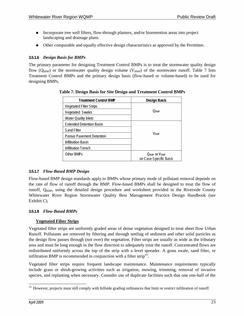
3.5.1.6 Design Basis for BMPs
The primary parameter for designing Treatment Control BMPs is to treat the stormwater quality design flow (QBMP) or the stormwater quality design volume (VBMP) of the stormwater runoff. Table 7 lists Treatment Control BMPs and the primary design basis (flow-based or volume-based) to be used for designing BMPs.
Table 7. Design Basis for Site Design and Treatment Control BMPs
Treatment Control BMP Design Basis
Vegetated Filter Strips
Vegetated Swales
Water Quality Inlets
QBMP
Extended Detention Basin
Sand Filter
Porous Pavement Detention
Infiltration Basin
Infiltration Trench
VBMP
Other BMPs QBMP or VBMP
on Case-Specific Basis
3.5.1.7 Flow-Based BMP Design
Flow-based BMP design standards apply to BMPs whose primary mode of pollutant removal depends on the rate of flow of runoff through the BMP. Flow-based BMPs shall be designed to treat the flow of runoff, QBMP, using the detailed design procedure and worksheet provided in the Riverside County Whitewater River Region Stormwater Quality Best Management Practice Design Handbook (see Exhibit C).
3.5.1.8 Flow-Based BMPs
Vegetated Filter Strips
Vegetated filter strips are uniformly graded areas of dense vegetation designed to treat sheet flow Urban Runoff. Pollutants are removed by filtering and through settling of sediment and other solid particles as the design flow passes through (not over) the vegetation. Filter strips are usually as wide as the tributary area and must be long enough in the flow direction to adequately treat the runoff. Concentrated flows are redistributed uniformly across the top of the strip with a level spreader. A grass swale, sand filter, or infiltration BMP is recommended in conjunction with a filter strip14.
Vegetated filter strips require frequent landscape maintenance. Maintenance requirements typically include grass or shrub-growing activities such as irrigation, mowing, trimming, removal of invasive species, and replanting when necessary. Consider use of duplicate facilities such that one one-half of the
14 However, projects must still comply with hillside grading ordinances that limit or restrict infiltration of runoff.
Whitewater River Region WQMP Public Review Draft
April 2009 24
facility can be taken out of service to allow for maintenance without reducing the required level of treatment performance. This is especially helpful for vegetated filter strips that need to be dry before they can be mowed.
Vegetated Swales
A vegetated swale is a wide, shallow densely vegetated channel that treats Urban Runoff as it is slowly conveyed into a downstream system. These swales have very shallow slopes in order to allow maximum contact time with the vegetation. The depth of the design flow should be less than the height of the vegetation15. Contact with vegetation improves water quality by plant uptake of pollutants, removal of sediment, and an increase in infiltration. Overall the effectiveness of grass swales is limited and they are recommended in combination with other BMPs.
Vegetated swales require a thick vegetative cover to function properly. They usually require normal landscape maintenance activities such as irrigation and mowing to maintain pollutant removal efficiency. The application of fertilizers and pesticides should be minimized. Consider use of duplicate facilities such that one one-half of the facility can be taken out of service to allow for maintenance without reducing the required level of treatment performance. This is especially helpful for vegetated swales that need to be dry before they can be mowed.
Water Quality Inlet
A water quality inlet is a device that removes oil and grit from Urban Runoff before the water enters the MS4. It consists of one or more chambers that promote sedimentation of coarse materials and separation of free oil from Urban Runoff. Manufacturers have created a variety of configurations to accomplish this. A specific model can be selected from the manufacturer based on the design flow rate. A water quality inlet is generally used for pretreatment before discharging into another type of BMP.
Water quality inlet maintenance is site-specific due to variations in sediment and hydrocarbon by-products, which may require disposal as hazardous waste. Establishment of a maintenance schedule is helpful for ensuring proper maintenance, because water quality inlets are underground and can easily be neglected. High sediment loads can interfere with the ability of a water quality inlet to effectively separate oil and grease from the runoff.
Other BMPs
In some cases, other flow-based BMPs, proprietary BMPs or combinations of BMPs may be appropriate for a development. Such BMPs or combinations of BMPs may be employed on a site-specific basis as approved by the Permittee. The appropriate BMP(s) for a project should be determined based on the size of the project area and the Pollutants of Concern that will be found in the development runoff.
3.5.1.9 Volume-Based BMP Design
Volume-based BMP design standards apply to BMPs whose primary mode of pollutant removal depends on the volumetric capacity of the BMP. Volume-based BMPs shall be designed to infiltrate or treat the volume of runoff, VBMP, using the detailed design procedure and worksheet provided in the Riverside County Whitewater River Region Stormwater Quality Best Management Practice Design Handbook (see Exhibit C).
15 However, projects must still comply with hillside grading ordinances that limit or restrict infiltration of runoff.
Whitewater River Region WQMP Public Review Draft
April 2009 25
3.5.1.10 Volume-Based BMPs
Extended Detention Basin
An extended detention basin is a permanent basin sized to detain and slowly release the design volume of Urban Runoff, allowing particles and associated pollutants to settle out. The basin outlet is designed to slowly release this runoff over a set drawdown period. An inlet forebay section and an inlet energy dissipater minimize erosion from entering flows, while erosion protection at the outlet prevents damage from exiting flows. The bottom of the basin slopes towards the outlet at an approximate grade of two percent, and a low flow channel conveys incidental flows directly to the outlet end of the basin. The basin should be vegetated earth in order to allow some infiltration to occur, although highly pervious soils may require an impermeable liner to prevent groundwater contamination. Proper turf management is also required to ensure that the vegetation does not contribute to water pollution through pesticides, herbicides, or fertilizers. A permanent micro-pool should not be included due to vector concerns. Extended detention basins can also be used to reduce the peaks of small run-off events for flood control purposes.
Extended detention basins require inspection semi-annually and after significant storm events to identify potential problems early. Most maintenance efforts will need to be directed toward vegetation management and vector control, which may focus on basic housekeeping practices such as removal of debris accumulations and vegetation management to ensure that the basin dewaters completely, within the set drawdown time, to prevent creating vector habitats.
Infiltration Basin
Infiltration basins perform better in well-drained permeable soils. Infiltration basins in areas of low permeability can clog within a couple of years, and require more frequent inspection and maintenance. The use and regular maintenance of pretreatment BMPs will significantly minimize maintenance requirements for the basin. Spill response procedures and controls should be implemented to prevent spills from reaching the infiltration basin. Particular care is required where the area upstream of the infiltration BMP may not be fully stabilized, or in existing developments where upstream areas may become destabilized due to construction work, lack of maintenance, fire, or other actions. In these cases, measures to prevent sediment from entering and clogging the BMP are necessary until the tributary area is stabilized. This BMP may require groundwater monitoring. Basins should not be put into operation until the upstream tributary area is stabilized.
Infiltration Trench
An infiltration trench is an excavated trench that has been refilled with a gravel and sand bed capable of holding the design volume of Urban Runoff. The runoff is stored in the trench over a period of time during which it slowly infiltrates back into the naturally pervious surrounding soil. This infiltration process effectively removes soluble and particulate pollutants, however it is not intended to trap coarse sediments. These trenches also include a bypass system for volumes greater than the design capture volume, and a perforated pipe observation well to monitor water depth.
Infiltration trenches require an effective pretreatment, such as vegetated buffer strips, to remove sediment and minimize clogging. If the trench clogs, it may be necessary to remove and replace all or part of the filter fabric and possibly the coarse aggregate. Maintenance should be concentrated on the pretreatment practices, such as buffer strips and swales upstream of the trench to ensure that sediment does not reach the infiltration trench. Particular care is required where the area upstream of the infiltration BMP may not be fully stabilized, or in existing developments where upstream areas may become destabilized due to
Whitewater River Region WQMP Public Review Draft
April 2009 26
construction work, lack of maintenance, fire, or other actions. In these cases, measures to prevent sediment from entering and clogging the BMP are necessary until the tributary area is stabilized. Regular inspection should determine if the sediment removal structures require routine maintenance. Infiltration basins should not be put into operation until the upstream tributary area is stabilized.
Sand Filter
Sand filters clog easily when subjected to heavy sediment loads. Sediment reducing pretreatment practices, such as vegetated buffer strips or vegetated swales, placed upstream of the filter should be maintained properly to reduce sediment loads into the filter. Media filters should drain within the set drawdown time to minimize vector habitat. Maintenance will need to focus on basic housekeeping practices such as removal of debris accumulations and vegetation management (within media filter) to prevent clogs and/ or standing water. Materials such as sand, gravel, filter cloth, or filter media must be disposed of properly and in accordance with all applicable laws.
Porous Pavement
Porous pavement is an infiltration BMP that consists of porous pavement blocks placed over a shallow recharge bed of sand and gravel. It is typically restricted to low volume parking areas that do not receive significant offsite runoff. The modular pavement blocks allow water to seep into the recharge bed, where the sand and gravel layers percolate the design volume into the natural surrounding soils. Porous Pavement can be used for areas of up to 10 acres.
Other BMPs
In some cases, other volume-based BMPs, proprietary BMPs or combinations of BMPs may be appropriate for a development. Such BMPs or combinations of BMPs may be employed on a site-specific basis as approved by the Permittee. The appropriate BMP(s) for a project should be determined based on the size of the project area and the Pollutants of Concern that will be found in the development runoff.
3.5.2 Source Control BMPsThe following Source Control BMPs must be addressed in each project-specific WQMP unless they do not apply given project features as determined by the Permittee. If any of the following Source Control BMPs are not included in the project-specific WQMP, adequate justification must be provided before the project-specific WQMP will be approved.
3.5.2.1 Non-Structural Source Control BMPs
Education/Training for Property Owners, Operators, Tenants, Occupants, or Employees
For projects with an HOA/POA of less than fifty (50) dwelling units and for projects with no HOA/POA, practical informational materials to promote the prevention of Urban Runoff pollution will be provided by the project proponent to the first residents/occupants/tenants. These materials shall include general housekeeping practices that contribute to the protection of Urban Runoff quality and BMPs that eliminate or reduce pollution during subsequent property improvements. These materials or a resource list for obtaining these materials will be made available through the Permittee or can be found at http://www.floodcontrol.co.riverside.ca.us/YouCanHelp.asp. However, the Permittee may elect to recover printing costs for such materials. The project applicant shall request these materials at least 30 days prior to the intended distribution date and shall then be responsible for timely distribution at the time of occupancy.
Whitewater River Region WQMP Public Review Draft
April 2009 27
For projects with an HOA/POA of more than fifty (50) dwelling units, conditions of approval will require the HOA/POA to annually provide environmental awareness education materials to all members. These materials shall include general housekeeping practices that contribute to the protection of Urban Runoff quality and BMPs that eliminate or reduce pollution during subsequent property improvements. These materials or a resource list for obtaining these materials will be available through the Permittee. However, the Permittee may elect to recover printing costs for such materials. The HOA/POA shall request these materials (in writing) at least 30 days prior to the intended distribution date.
For projects where people will be employed or contracted to perform activities that may impact Urban Runoff, BMP training and education programs must be provided to all new employees within 6 months of hire date and annually thereafter. Employee training materials may be derived from educational materials available through the Permittee or from other resources such as “Stormwater Best Management Practices Handbook for Industrial and Commercial” (CASQA, 2003). The most recent editions of the CASQA handbooks can be downloaded at www.cabmphandbooks.com. The project-specific WQMP must describe the frequency of employee training and indicate the party responsible for conducting the training.
Activity Restrictions
At the discretion of the Permittee, if an HOA/POA is formed, the developer shall prepare CC&Rs for the purpose of Receiving Water quality protection. Alternatively, use restrictions may be developed by a building operator through lease terms, etc. These restrictions must be included in the project-specific WQMP. Examples of activity restrictions are:
Prohibiting the blowing, sweeping, or hosing of debris (leaf litter, grass clippings, litter, etc.) into streets, storm drain inlets, or other conveyances.
Require dumpster lids to be closed at all times.
Prohibit vehicle washing, maintenance, or repair on the premises or restrict those activities to designated areas (such as repair within maintenance bays and vehicle washing on properly designed wash racks).
Irrigation System and Landscape Maintenance
Maintenance of irrigation systems and landscaping shall be consistent with the Permittee’s water conservation ordinance, which can be accessed through the Permittee’s website or obtained through the Permittee’s planning/permitting counter. Fertilizer and pesticide usage shall be consistent with the instructions contained on product labels and with regulations administered by California’s Department of Pesticide Regulation. Additionally, landscape maintenance must address replacement of dead vegetation, repair of erosion rills, proper disposal of green waste, etc. Irrigation system maintenance must address periodic testing and observation of the irrigation system to detect overspray, broken sprinkler heads, and other system failures. The project-specific WQMP should describe the anticipated frequency of irrigation system and landscape maintenance activities and identify the responsible party.
Common Area Litter Control
For industrial/commercial projects and for projects with HOAs/POAs, the project-specific WQMP must address litter control for common areas. Litter control must address whether or not trash receptacles willbe provided in common areas, emptying of trash receptacles, the frequency with which trash receptacles will be emptied, patrolling common areas and perimeter fences or walls to collect litter, noting trash disposal violations by tenants/home owners or businesses and reporting such observations to the owner,
Whitewater River Region WQMP Public Review Draft
April 2009 28
operator, manager, or HOA/POA for investigation, and identification of the party responsible for litter control.
Street Sweeping Private Streets and Parking Lots
For industrial/commercial projects and for other projects with HOAs/POAs, the frequency of sweeping privately owned streets shall be described in the project-specific WQMP. The frequency shall be no less than the frequency of street sweeping by the Permittee on public streets. For projects with parking lots, the parking lots shall be swept at least quarterly, including just prior to the start of the rainy season (October 1st). The project-specific WQMP should identify the anticipated sweeping frequency, source of funding and the party responsible for conducting the periodic sweeping.
Drainage Facility Inspection and Maintenance
For industrial/commercial projects and for projects with HOAs/POAs, the frequency for cleaning privately owned drainage facilities (catch basins, open channels and storm drain inlets) shall be described in the project-specific WQMP. The frequency shall be no less than the frequency of drainage facility cleaning conducted by the Permittee. At a minimum, routine maintenance of privately owned drainage facilities should take place in the late summer or early fall prior to the start of the rainy season (October 1st). The drainage facilities must be cleaned if accumulated sediment/debris fills 25% or more of the sediment/debris storage capacity. Privately owned drainage facilities shall be inspected annually and the cleaning frequency shall be assessed. The project-specific WQMP should identify the party responsible for conducting the drainage facility inspection and maintenance.
3.5.2.2 Structural Source Control BMPs
Storm Drain Inlet Stenciling and Signage
The following requirements must be addressed in a project-specific WQMP and/or shall be denoted on project plan sheets:
Provide stenciling or labeling of all storm drain inlets and catch basins, constructed or modified, within the project area with prohibitive language (such as: “NO DUMPING ONLY RAIN IN THE DRAIN”) and/or graphical icons to discourage illegal dumping.
Post signs and prohibitive language and/or graphical icons, which prohibit illegal dumping at public access points along channels and creeks within the project area.
Identify the party responsible for maintaining the legibility of stencils and signs.
The stencils contain a brief statement that prohibits dumping into the MS4. Graphical icons, either illustrating anti-dumping symbols or images of Receiving Water fauna, are effective supplements to the text message. Stencils and signs alert the public to the destination of pollutants discharged into Urban Runoff.
Landscape and Irrigation System Design
A project-specific WQMP must describe how the following concepts have been incorporated into project design features:
Employing rain shutoff devices to prevent irrigation during and after precipitation events.
Designing irrigation systems to each landscape area’s specific water requirements.
Whitewater River Region WQMP Public Review Draft
April 2009 29
Using flow reducers or shutoff valves triggered by a pressure drop to control water loss due to broken sprinkler heads or lines.
The timing and application methods of irrigation water shall be designed to minimize the runoff of excess irrigation water into the MS4.
Other comparable, equally effective, methods to reduce irrigation water runoff.
Preparation and implementation of a landscape plan consistent with the Permittee’s water conservation ordinance, which may include the use of water sensors, programmable irrigation times (for short cycles), etc.
Preparation and implementation of a landscape plan that:
– Utilizes plants with low irrigation requirements (for example, native or drought tolerant species)
– Groups plants with similar water requirements in order to reduce excess irrigation runoff and promote surface infiltration.
– Use mulches (such as wood chips or shredded wood products) in planter areas without ground cover to minimize sediment in runoff.
– Install appropriate plant materials for the location, in accordance with amount of sunlight and climate, and use native plant material where possible and/or as recommended by the landscape architect.
– Maintaining or creating a vegetative barrier along the property boundary and interior watercourses, to act as a pollutant filter, where appropriate and feasible.
– Choose plants that minimize or eliminate the use of fertilizer or pesticides to sustain growth.
Protection of Slopes and Channels
Project plans shall include Source Control BMPs to decrease the potential for erosion of slopes and/or channels, consistent with local codes and ordinances and with the approval of all agencies with jurisdiction, e.g., the U.S. Army Corps of Engineers, the Regional Board and the California Department of Fish and Game. The following design principles shall be considered, and incorporated and implemented where determined applicable and feasible by the Permittee:
Convey runoff safely from the tops of slopes.
Avoid disturbing steep or unstable slopes and natural channels.
Install permanent stabilization BMPs on disturbed slopes as quickly as possible.
Plant slopes with native or drought tolerant vegetation. Hillside areas that are disturbed shall be landscaped with deep-rooted, drought tolerant plant species selected for erosion control.
Control and treat flows in landscaping and/or other controls prior to reaching existing natural drainage systems.
Install permanent stabilization BMPs in channel crossings as quickly as possible, and ensure that increases in runoff velocity and frequency caused by the project do not erode the channel.
Install energy dissipaters at the outlets of new MS4s, culverts, conduits, or channels that enter unlined channels in accordance with applicable specifications to minimize erosion. Energy dissipaters shall be installed in such a way as to minimize impacts to Receiving Waters.
Onsite conveyance channels should be lined, where appropriate, to reduce erosion caused by increased flow velocity due to increases in tributary impervious area. The first choice for linings
Whitewater River Region WQMP Public Review Draft
April 2009 30
should be grass or some other vegetative surface, since these materials not only reduce runoff velocities, but also provide water quality benefits from filtration and infiltration. If velocities in the channel are large enough to erode grass or other vegetative linings, riprap, concrete soil cement or geo-grid stabilization may be substituted or used in combination with grass or other vegetation stabilization.
Other comparable and equally effective site design options as approved by the Permittee.
Provide Community Car Wash Racks
In multi-family projects where car washing or rinsing is not specifically prohibited via CC&Rs or other acceptable means, and in projects having a common parking area where car washing or rinsing is not specifically prohibited via CC&Rs or other acceptable means, a designated car washing and rinsing area that does not drain directly to a MS4 shall be provided for common usage. Wash and rinse waters from this area must either be directed to the sanitary sewer (with prior approval of the sewering agency), to an engineered filtration system, or an equally effective alternative prior to discharging to the MS4.
Properly Design and Maintain Fueling Areas
Fuel dispensing areas shall include the following design features:
At a minimum, the fuel dispensing area must extend 6.5 feet (2.0 meters) from the corner of each fuel dispenser, or the length at which the hose and nozzle assembly may be operated plus 1 foot (0.3 meter), whichever is less.
The fuel dispensing area shall be paved with Portland cement concrete (or equivalent smooth impervious surface). The use of asphalt concrete is prohibited.
The fuel dispensing area shall have an appropriate slope (2% - 4%) to prevent ponding, and must be separated from the rest of the site by a grade break that prevents run-on of stormwater and to eliminate stormwater flow through the concrete fueling area.
An overhanging roof structure or canopy shall be provided. The cover’s minimum dimensions must be equal to or greater than the area within the grade break or the fuel dispensing area. The cover must not drain onto the fuel dispensing area and facility downspouts (roof drains) must be routed to prevent drainage across the fueling area. The fueling area shall drain to an appropriate Treatment Control BMP prior to discharging to the MS4.
The fuel dispensing area must be designed to prohibit spills from draining to the street, MS4, or offsite.
Properly Design Air/Water Supply Area Drainage
Areas used for air/water supply must be graded and constructed so as to contain spilled material for cleanup.
Properly Design and Maintain Trash Storage Areas
All trash container areas shall meet the following requirements:
Paved with an impervious surface, designed not to allow run-on from adjoining areas, designed to divert drainage from adjoining roofs and pavements diverted around the area, screened or walled to prevent off-site transport of trash.
Trash dumpsters (containers) shall be leak proof and have attached covers or lids.
Connection of trash area drains to the MS4 is prohibited.
Whitewater River Region WQMP Public Review Draft
April 2009 31
Trash compactors shall be roofed and set on a concrete pad. The pad shall be a minimum of one foot larger all around than the trash compactor and sloped to drain to a sanitary sewer line.
Properly Design and Maintain Loading Docks
The design of loading/unloading dock areas shall include the following:
Cover loading dock areas, or design drainage to preclude run-on and runoff.
Direct connections to the MS4 from below-grade loading docks (truck wells) or similar structures are prohibited. Urban Runoff from a below-grade loading dock may only be discharged to the MS4 when designed to use a Treatment Control BMP applicable to the use.
Loading docks shall be kept in a clean and orderly condition through a regular program of sweeping and litter control and immediate cleanup of spills and broken containers. Cleanup procedures should minimize or eliminate the use of water. If washdown water is used, it must be properly disposed (containment, collection, and disposal to sanitary sewer) and not discharged to the MS4. The project-specific WQMP shall describe the frequency for implementing loading dock housekeeping measures and the party responsible.
Properly Design and Maintain Maintenance Bays
Maintenance bays shall include the following:
Repair/maintenance bays shall be indoors; or, designed to preclude run-on and runoff.
Design a repair/maintenance bay drainage system to capture all wash water, leaks and spills. Provide impermeable berms, drop inlets, trench catch basins, or overflow containment structures around repair bays to prevent spilled materials and washdown waters from entering the MS4. Connect drains to a sump for collection and disposal. Discharge from the repair/maintenance bays to the MS4 is prohibited.
Properly Design and Maintain Vehicle and Equipment Wash Areas
The discharge of wash waters to the MS4 is prohibited. Therefore, projects that include areas for washing/steam cleaning of vehicles or equipment shall include the following design features:
Wash areas shall be contained and covered with a roof or overhang or adequate surplus storage to contain and utilize all precipitation.
Provide a wash rack or wash racks connected to the sanitary sewer in accordance with sewering agency guidelines and prior approval. The sewering agency may require discharge monitoring. If the facility recycles wash water and is not connected to the sanitary sewer, wastes must be properly contained and disposed.
Design an equipment wash area drainage system to capture all wash water. Provide impermeable berms, drop inlets, trench catch basins, or overflow containment structures around equipment wash areas to prevent wash waters from entering the MS4. Connect drains to a sump for collection and disposal.
Surface runoff and roof drains shall be directed away from wash racks unless approved by the sanitary sewering agency.
Properly Design and Maintain Outdoor Material Storage Areas
Where plans propose outdoor storage containers for oils, fuels, solvents, coolants, wastes, and other chemicals, the areas where these materials are to be used or stored must be protected by secondary
Whitewater River Region WQMP Public Review Draft
April 2009 32
containment structures such as a low containment berm, dike, or curb, designed to the satisfaction of the Permittee. Materials or products that are stored outside and that have the potential to cause pollutant discharges shall be protected from rainfall, runoff, run-on, and wind erosion by design and use of a:
cabinet, shed, or similar structure that prevents contact with runoff or spillage to the MS4;
paved storage area and sufficiently impervious to contain leaks and spills; and/or
roof or awning to minimize direct precipitation and collection of stormwater within the secondary containment area. Stormwater that collects within a secondary containment structure must not be discharged to the street or the MS4.
Properly Design and Maintain Outdoor Work Areas or Processing Areas
Where vehicle or equipment repair/maintenance occurs, impermeable berms, trench drains, or containment structures shall be provided around the areas to eliminate or reduce spilled materials and wash-down waters from entering the street or the MS4. Surface runoff or roof drains shall be directed away from these contained work areas. Sidewalls and canopies may be used to meet this requirement.
Outdoor process equipment operations, such as rock grinding or crushing, painting or coating, grinding or sanding, degreasing or parts cleaning, landfills, waste piles, and wastewater and solid waste handling, treatment, and disposal, and other operations shall adhere to the following requirements.
Cover or enclose areas that would be the sources of pollutants or slope the area toward a sump.
Grade or berm area to prevent run-on from surrounding areas.
Storm drain inlets connected to the MS4 are prohibited within these outdoor work or process areas.
Where wet material processing occurs (e.g. electroplating), secondary containment structures (not double wall containers) shall be provided to hold spills resulting from accidents or leaking tanks or equipment.
Salvage yards and recycle facilities must direct all runoff to appropriate Treatment Control BMP(s).
Provide Wash Water Controls for Food Preparation Areas
Food establishments (per State Health & Safety Code 27520) shall have either contained areas or sinks, each with connections to the sanitary sewer for disposal of wash waters containing kitchen and food wastes. If located outside, the contained areas or sinks shall also be structurally covered to prevent entry of Urban Runoff. Adequate signs shall be provided and appropriately placed stating the prohibition of discharging wash water to the MS4.
3.5.3 Equivalent Treatment Control Alternatives
Where off-site Treatment Control BMPs are determined to be more feasible or practicable, equivalent treatment may be provided off site when approved by the Permittee. Off-site Treatment Control BMPs must:
Be located in the same watershed as the project site.
Treat a volume and/or flow equal to or greater than the treatment volume and/or flow calculated for the project site using the guidance in this WQMP.
Treat a pollutant loading equal to or greater than the pollutant loading from the project site.

Whitewater River Region WQMP Public Review Draft
April 2009 33
Address the Pollutants of Concern and Hydrologic Conditions of Concern not addressed at the project site.
Have BMP capacity functional prior to the issuance of occupancy permits, or certificates of use (or equivalent), if no occupancy permits are issued.
Off-site BMPs must be implemented prior to proximate Receiving Waters.
Off-site Treatment Control BMPs shall not cause water quality impairment or contribute to exceedances of water quality objectives.
In addition, Site Design and Source Control BMPs must continue to be implemented at the project site in accordance with this WQMP.
Subject to approval by the Permittee, off-site Treatment Control BMPs with excess capacity may be used to meet the treatment needs of additional projects as long as each project meets the requirements of this section and such that the requirements are met when the projects are combined. For example, if the treatment volume for project 1 is “A” and the treatment volume for project 2 is “B”, then an off-site Treatment Control BMP would need to have a treatment volume capacity of at least “A+B” in order to treat the runoff from both project 1 and project 2. Similar provisions apply for flows and pollutants.
These provisions are supplemental to the provisions in Section 4 for regionally-based water quality control programs. While similar in nature, these provisions are intended to be implemented primarily on a smaller, more local basis. For example, a single developer of separate but adjacent projects might utilize the provisions of this section to propose that controls for both projects be located on one of the two separate sites, or possibly even propose that the controls for both sites be located on a third site.
3.6 Operation and Maintenance
Operation and maintenance (O&M) requirements for all structural Source Control and Treatment Control BMPs shall be identified in the project-specific WQMP. The project-specific WQMP shall address the following:
Identification of each BMP that requires O&M.
Thorough description of O&M activities, the O&M process, and the handling and placement of any wastes.
BMP start-up dates.
Schedule of the frequency of O&M for each BMP.
Identification of the parties (name, address, and telephone number) responsible for O&M, including a written agreement with the entities responsible for O&M. This agreement can take the form of a Covenant and Agreement recorded by the project applicant with the County Recorder, HOA or POA CC&Rs, formation of a maintenance district or assessment district or other instrument sufficient to guarantee perpetual O&M. Examples of requirements for typical maintenance mechanisms and a sample of a Covenant and Agreement are available in Exhibit E and F, respectively. Project applicants should speak to the Permittee for Permittee-specific requirements.
Self-inspections and record-keeping requirements for BMPs (review local specific requirements regarding self-inspections and/or annual reporting), including identification of responsible parties for inspection and record- keeping.
Thorough descriptions of water quality monitoring, if required by the Permittee.
Whitewater River Region WQMP Public Review Draft
April 2009 34
Permittees should have authority to maintain the BMP, if necessary, and invoice the owner for costs.
3.7 Funding
A funding source or sources for the O&M of each Treatment Control BMP identified in the project-specific WQMP must be identified. By certifying the project-specific WQMP (see Section 3.8), the project applicant is certifying that the funding responsibilities have been addressed and will be transferred to future owners. One example of how to adhere to the requirement to transfer O&M responsibilities is to record the project-specific WQMP against the title to the property.
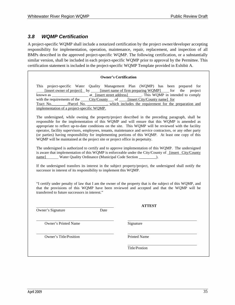
Whitewater River Region WQMP Public Review Draft
April 2009 35
3.8 WQMP Certification
A project-specific WQMP shall include a notarized certification by the project owner/developer accepting responsibility for implementation, operation, maintenance, repair, replacement, and inspection of all BMPs described in the approved project-specific WQMP. The following certification, or a substantially similar version, shall be included in each project-specific WQMP prior to approval by the Permittee. This certification statement is included in the project-specific WQMP Template provided in Exhibit A.
Owner’s Certification
This project-specific Water Quality Management Plan (WQMP) has been prepared for [insert owner of project] by [insert name of firm preparing WQMP] for the project
known as ___________________ at [insert street address] . This WQMP in intended to comply with the requirements of the City/County of [insert City/County name] for Tract No.________/Parcel No. __________, which includes the requirement for the preparation and implementation of a project-specific WQMP.
The undersigned, while owning the property/project described in the preceding paragraph, shall be responsible for the implementation of this WQMP and will ensure that this WQMP is amended as appropriate to reflect up-to-date conditions on the site. This WQMP will be reviewed with the facility operator, facility supervisors, employees, tenants, maintenance and service contractors, or any other party (or parties) having responsibility for implementing portions of this WQMP. At least one copy of this WQMP will be maintained at the project site or project office in perpetuity.
The undersigned is authorized to certify and to approve implementation of this WQMP. The undersigned is aware that implementation of this WQMP is enforceable under the City/County of [insert City/County name] Water Quality Ordinance (Municipal Code Section _________).
If the undersigned transfers its interest in the subject property/project, the undersigned shall notify the successor in interest of its responsibility to implement this WQMP.
“I certify under penalty of law that I am the owner of the property that is the subject of this WQMP, and that the provisions of this WQMP have been reviewed and accepted and that the WQMP will be transferred to future successors in interest.”
ATTESTOwner’s Signature Date
Owner’s Printed Name Signature
Owner’s Title/Position Printed Name
Title/Postion
Whitewater River Region WQMP Public Review Draft
April 2009 36
4.0 Regionally-Based Treatment ControlFor watersheds, sub-watershed, tributary areas, and other areas covered by a comprehensive Master Plan of Drainage approved by the Permittee(s) (or developed as part of a Master Plan of Drainage for a Specific Plan or a cooperative group of developments), regionally-based Treatment Control BMPs are an alternative approach to project-specific (onsite) Treatment Control BMP implementation. Regionally-based BMPs may provide a more effective and cost efficient runoff Treatment Control mechanism for multiple projects within the area covered by the comprehensive master plan of drainage and water quality. Regional BMPs may also provide opportunities for public/private partnerships where pollutants of concern from existing developments within the area covered by the master plan of drainage can also be addressed by the Regional BMPs capacity.
It may be possible that a regionally-based Treatment Control BMP will address all Pollutants of Concernand Hydrologic Conditions of Concern for a particular project. The operating entity of an existing regionally based Treatment Control BMP (Regional BMP) shall be able to provide project proponents in the vicinity of the Regional BMP with information describing the tributary area the Regional BMP was designed to mitigate and the Pollutants of Concern and/or Hydrologic Conditions of Concern the Regional BMP addresses. The project proponent is responsible for identifying the Pollutants of Concernand/or Hydrologic Conditions of Concern associated with the project, comparing those with the Pollutants of Concern and/or Hydrologic Conditions of Concern addressed by the Regional BMP, and determining what additional on-site BMPs are required to treat Pollutants of Concern and/or Hydrologic Conditions of Concern not addressed by the Regional BMP.
When regionally-based Treatment Control BMPs are utilized, the project must continue to implement Site Design and Source Control BMPs. Regionally-based Treatment Control BMPs can treat Urban Runoff from several source areas at a single or multiple downstream location(s). This approach can be effective when limited space is available for structural BMPs in project areas. Regionally-based Treatment Control BMPs will be considered for acceptance by the Permittee as an alternative to on-site measures if the project applicant demonstrates the following (italicized requirements apply only to project proponents proposing new regionally-based BMPs):
There is adequate capacity in the regionally-based Treatment Control BMP to address the volume-based and flow-based treatment needs of the project.
The regionally-based Treatment Control BMP addresses the project’s Pollutants of Concern (after considering Site Design and Source Control BMPs that must still be implemented at the project site).
Projects intending to rely on the regionally-based Treatment Control BMP must incorporate project-specific BMPs to address any pollutant of concern from the project not addressed by the regionally-based Treatment Control BMP.
The project applicant identifies the party responsible for the funding, operation, maintenance, and administration of the regionally-based Treatment Control BMP.
The project applicant has secured rights from the owner/operator to participate in the regionally-based BMP solution.
The project applicant has met all of the requirements imposed for participation in the regionally-based BMP, including funding and operation and maintenance requirements, and contingency planning.
Whitewater River Region WQMP Public Review Draft
April 2009 37
Regional BMP capacity must be functional prior to the issuance of occupancy permits, or certificates of use (or equivalent), if no occupancy permits are issued.
Waters of the United States will not be utilized to transport untreated Urban Runoff to the regional facility.
The ability of the regionally-based BMP to address Total Maximum Daily Load (TMDL) requirements for any adopted TMDLs. If a regionally-based BMP does not address TMDL requirements, additional on-site BMPs may be required to address applicable TMDL related Pollutants of Concern.
Projects participating in regional Treatment Control BMPs may rely upon the regional program during the discretionary review process subject to a discussion of how the project will participate in the program. At the discretion of the Permittee(s) with jurisdiction, the project-specific WQMP may be required to identify its Urban Runoff contribution to the regional program and how it will affect cumulative water quality impacts in the regional watershed. Removal effectiveness, cost, maintenance, and construction timing affect whether a regional-based approach is more appropriate than site-specific approaches.
The Permittee(s) with jurisdiction over the project should be contacted to determine if regional BMPs exist or are proposed. A project that proposes to utilize a regional BMP must verify that the regional BMP addresses all Pollutants of Concern from the project. A project’s Pollutants of Concern that are not addressed by the regional BMP will require a separate Treatment Control BMP (or BMPs).
5.0 Changes in Site Development or Ownership
5.1 Changes in Site Development
The WQMP must be updated to reflect significant proposed changes in the site’s runoff characteristics. Potentially significant changes in the site runoff characteristics are deemed to exist whenever site work requiring a grading permit is proposed or where exterior work requiring a building permit is proposed. Under these circumstances, the owner/developer shall contact the Permittee and provide sufficient information for the Permittee to determine whether the existing project-specific WQMP is still appropriate. If deemed inappropriate by the Permittee for proposed conditions, the owner/developer shall revise the WQMP to address the cumulative changes to the site and submit the revised project-specific WQMP to the Permittee for review and approval prior to issuance of the first discretionary permit.
Significant changes in the site’s runoff characteristics shall be deemed to occur whenever there is a change in use necessitating a conditional use permit (for example, changing from retail to restaurant), or when proposed changes to the site fall into one or more of the project categories that require a project-specific WQMP. Under these conditions, a revised or completely new project-specific WQMP shall be developed and submitted for review and approval by the Permittee.
5.2 Changes in Site Ownership
For sites with a fully implemented WQMP, the WQMP requirements shall transfer to all future owners of the project site. The method to ensure transferability will depend on the method of O&M specified in the WQMP. Several O&M mechanisms, including a Covenant and Agreement recorded by the project applicant with the County Recorder, HOA or POA CC&Rs, formation of a maintenance district or assessment district or other instrument are considered sufficient to guarantee perpetual O&M. These mechanisms can also be used to ensure transferability of the project-specific WQMP. For example, when

Whitewater River Region WQMP Public Review Draft
April 2009 38
recording the WQMP requirements against the title to the property via a Covenant and Agreement, the Covenant and Agreement can also effectively notify potential buyers and future owners of properties of their responsibilities for the WQMP. An example of a Covenant and Agreement ensuring ongoing O&M and project-specific WQMP transferability is contained in Appendix F of this WQMP. Under this agreement, new owners have the option to adopt the existing project-specific WQMP, to amend the project-specific WQMP, or to develop a new project-specific WQMP. If the project-specific WQMP is amended or if a new project-specific WQMP is developed, the amended or new project-specific WQMP must be in accordance with this WQMP, must address cumulative changes to the project site, and must be submitted to the Permittee for review and approval. Similar requirements should be included as part of other O&M mechanisms or through separate agreements, if necessary.
6.0 Waiver of Treatment Control BMP RequirementsA waiver of Treatment Control BMP Requirements can be granted for any one of the following three conditions. For Conditions B and C, the Permittee must notify the Executive Officer of the Colorado River Basin Regional Water Quality Control Board of the waiver.
Condition A: Upon approval of a LID BMP Design Manual by the Executive Officer of the Colorado River Basin Regional Water Quality Control Board, Treatment Control BMPs may be eliminated, with the approval of the Permittee, if Site Design BMPs and Source Control BMPs are demonstrated to effectively eliminate discharges of Pollutants of Concern for the Flow-Based Design (Section 3.5.1.7) or Volume-Based Design (Section 3.5.1.9) criteria (Design Criteria). Upon presentation of a project-specific WQMP with sufficient Site Design and Source Control BMPs to meet the WQMP Design Criteria for discharges of Pollutants of Concern, and upon specific written request by the project applicant for a Treatment Control Waiver, the Permittee may approve a project-specific WQMP that does not include Treatment Control BMPs. The project applicant is responsible for the presentation of evidence, potentially including but not limited to monitoring data and special studies, to support the attainment of the WQMP objectives without the use of Treatment Control BMPs. The Riverside County Flood Control and Water Conservation District, in coordination with ongoing efforts by the California Stormwater Quality Association, is developing a LID BMP Design Manual that will incorporate the criteria to make these determinations.
Condition B: A Permittee may waive the requirement of incorporating Treatment Control BMPs into a project-specific WQMP for projects within those portions of the Permit Area that will not result in a discharge to Receiving Waters under the Design Criteria of MS4 Permit Section F.1.c.v.4. Upon presentation of a project-specific WQMP with sufficient evidence of no discharge to Receiving Waters under the WQMP Design Criteria, and upon specific written request by the project applicant for a Treatment Control Waiver, the Permittee may approve a project-specific WQMP that does not include Treatment Control BMPs. The project applicant is responsible for the presentation of evidence, potentially including but not limited to monitoring data and special studies, to support the attainment of the WQMP objectives without the use of Treatment Control BMPs. Permittees shall notify the Executive Officer of the Colorado River Basin Regional Water Quality Control Board by Certified Mail (with Return Receipt) within thirty (30) calendar days after issuing a waiver. The notification shall include a copy of documentation justifying the waiver.
Condition C: The Permittee may waive the requirement of incorporating Treatment Control BMPs into a project-specific WQMP on a case-by-case basis if infeasibility can be established. In considering a waiver of infeasibility, the Permittees should review the CEQA documentation for the project to
Whitewater River Region WQMP Public Review Draft
April 2009 39
determine whether a significant unmitigated impact or cumulative impact was identified that was the subject of a statement of overriding considerations. A Permittee shall only grant a waiver of infeasibility when all available Treatment Control BMPs have been considered and rejected as infeasible and/or the cost of implementing Treatment Control BMPs greatly outweighs the pollution control benefit. The burden of proof is on the project applicant to demonstrate that all available Treatment Control BMPs are infeasible. The Permittee shall notify the Executive Officer of the Colorado River Basin Regional Water Quality Control Board by Certified Mail (with Return Receipt) within thirty (30) calendar days after issuing a waiver. The notification shall include a copy of the documentation justifying the waiver.

Whitewater River Region WQMP Public Review Draft
April 2009
Exhibit A
Project-Specific WQMP Template

Whitewater River Region WQMP
Project SpecificWater Quality Management Plan
For:Project TitleLocation Address
DEVELOPMENT NO. TRACT, PARCEL OR OTHER ID NUMBERDESIGN REVIEW NO. DESIGN REVIEW NO.
Prepared for:
Name of Owner/DeveloperStreet AddressCity, State ZipTelephone: Telephone Number
Prepared by:Name and Title of PreparerCompany NameStreet AddressCity, State ZIPTelephone: Telephone
WQMP Preparation/Revision Date: Date
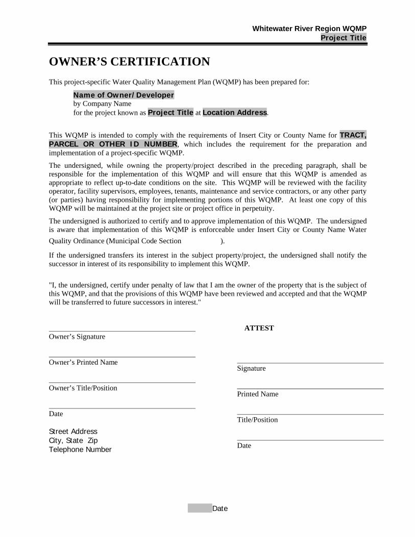
Whitewater River Region WQMPProject Title
Date
OWNER’S CERTIFICATION
This project-specific Water Quality Management Plan (WQMP) has been prepared for:
Name of Owner/Developerby Company Namefor the project known as Project Title at Location Address.
This WQMP is intended to comply with the requirements of Insert City or County Name for TRACT,PARCEL OR OTHER ID NUMBER, which includes the requirement for the preparation and implementation of a project-specific WQMP.
The undersigned, while owning the property/project described in the preceding paragraph, shall be responsible for the implementation of this WQMP and will ensure that this WQMP is amended as appropriate to reflect up-to-date conditions on the site. This WQMP will be reviewed with the facility operator, facility supervisors, employees, tenants, maintenance and service contractors, or any other party (or parties) having responsibility for implementing portions of this WQMP. At least one copy of this WQMP will be maintained at the project site or project office in perpetuity.
The undersigned is authorized to certify and to approve implementation of this WQMP. The undersigned is aware that implementation of this WQMP is enforceable under Insert City or County Name Water
Quality Ordinance (Municipal Code Section ).
If the undersigned transfers its interest in the subject property/project, the undersigned shall notify the successor in interest of its responsibility to implement this WQMP.
"I, the undersigned, certify under penalty of law that I am the owner of the property that is the subject of this WQMP, and that the provisions of this WQMP have been reviewed and accepted and that the WQMP will be transferred to future successors in interest."
ATTESTOwner’s Signature
Owner’s Printed Name
Owner’s Title/Position
Date
Street AddressCity, State ZipTelephone Number
Signature
Printed Name
Title/Position
Date
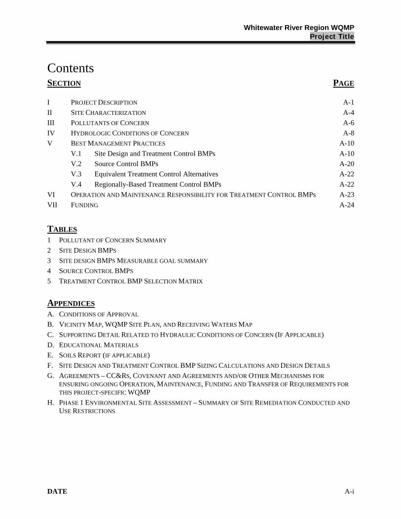
Whitewater River Region WQMPProject Title
DATE A-i
ContentsSECTION PAGE
I PROJECT DESCRIPTION A-1
II SITE CHARACTERIZATION A-4
III POLLUTANTS OF CONCERN A-6
IV HYDROLOGIC CONDITIONS OF CONCERN A-8
V BEST MANAGEMENT PRACTICES A-10
V.1 Site Design and Treatment Control BMPs A-10
V.2 Source Control BMPs A-20
V.3 Equivalent Treatment Control Alternatives A-22
V.4 Regionally-Based Treatment Control BMPs A-22
VI OPERATION AND MAINTENANCE RESPONSIBILITY FOR TREATMENT CONTROL BMPs A-23
VII FUNDING A-24
TABLES
1 POLLUTANT OF CONCERN SUMMARY
2 SITE DESIGN BMPS
3 SITE DESIGN BMPS MEASURABLE GOAL SUMMARY
4 SOURCE CONTROL BMPS
5 TREATMENT CONTROL BMP SELECTION MATRIX
APPENDICES
A. CONDITIONS OF APPROVAL
B. VICINITY MAP, WQMP SITE PLAN, AND RECEIVING WATERS MAP
C. SUPPORTING DETAIL RELATED TO HYDRAULIC CONDITIONS OF CONCERN (IF APPLICABLE)
D. EDUCATIONAL MATERIALS
E. SOILS REPORT (IF APPLICABLE)
F. SITE DESIGN AND TREATMENT CONTROL BMP SIZING CALCULATIONS AND DESIGN DETAILS
G. AGREEMENTS – CC&RS, COVENANT AND AGREEMENTS AND/OR OTHER MECHANISMS FOR
ENSURING ONGOING OPERATION, MAINTENANCE, FUNDING AND TRANSFER OF REQUIREMENTS FOR
THIS PROJECT-SPECIFIC WQMP
H. PHASE 1 ENVIRONMENTAL SITE ASSESSMENT – SUMMARY OF SITE REMEDIATION CONDUCTED AND
USE RESTRICTIONS

Whitewater River Region WQMPProject Title
DATE A-1
I. Project Description
Instructions:
The project description shall be completely and accurately described in narrative form. In the field provided on page A-3, describe and with supporting figures (maps or exhibits), where facilities will be located, what activities will be conducted and where, what kinds of materials will be used and/or stored, how and where materials will be delivered, and the types of wastes that will be generated. The following information shall be described and/or addressed in the "Project Description" section of the project-specific WQMP:
Project owner and WQMP preparer;
Project location;
Project size;
Standard Industrial Classification (SIC), if applicable;
Location of facilities;
Activities and location of activities;
Materials Storage and Delivery Areas;
Wastes generated by project activities.
Project Owner: Name of Owner/Developer
Street Address
City, State Zip
Telephone: Telephone Number
WQMP Preparer: Name and Title of Preparer
Street Address
City, State ZIP
Telephone: Telephone
Project Site Address: Insert Project Street Address
Insert Project City, State, ZIP
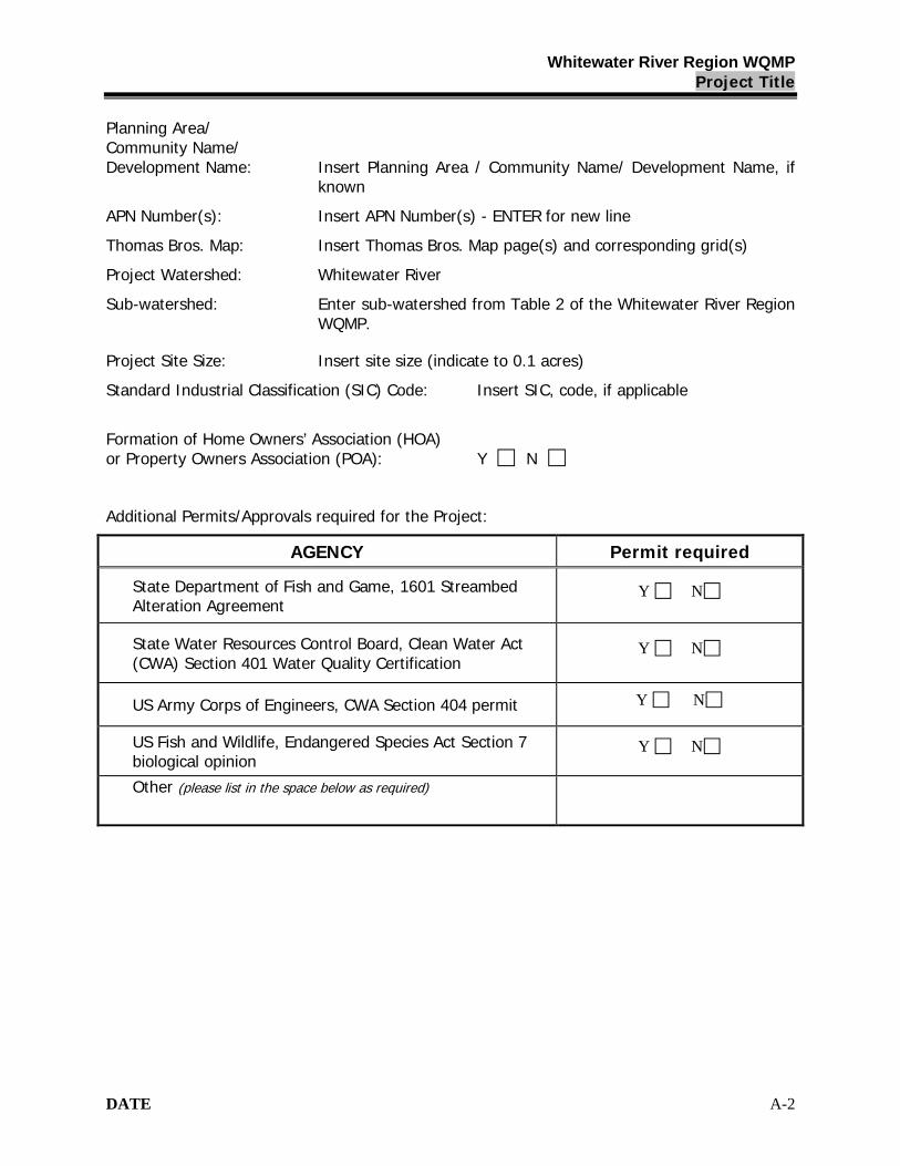
Whitewater River Region WQMPProject Title
DATE A-2
Planning Area/Community Name/Development Name: Insert Planning Area / Community Name/ Development Name, if
known
APN Number(s): Insert APN Number(s) - ENTER for new line
Thomas Bros. Map: Insert Thomas Bros. Map page(s) and corresponding grid(s)
Project Watershed: Whitewater River
Sub-watershed: Enter sub-watershed from Table 2 of the Whitewater River Region WQMP.
Project Site Size: Insert site size (indicate to 0.1 acres)
Standard Industrial Classification (SIC) Code: Insert SIC, code, if applicable
Formation of Home Owners’ Association (HOA)or Property Owners Association (POA): Y N
Additional Permits/Approvals required for the Project:
AGENCY Permit required
State Department of Fish and Game, 1601 Streambed Alteration Agreement
Y N
State Water Resources Control Board, Clean Water Act (CWA) Section 401 Water Quality Certification
Y N
US Army Corps of Engineers, CWA Section 404 permit Y N
US Fish and Wildlife, Endangered Species Act Section 7 biological opinion
Y N
Other (please list in the space below as required)
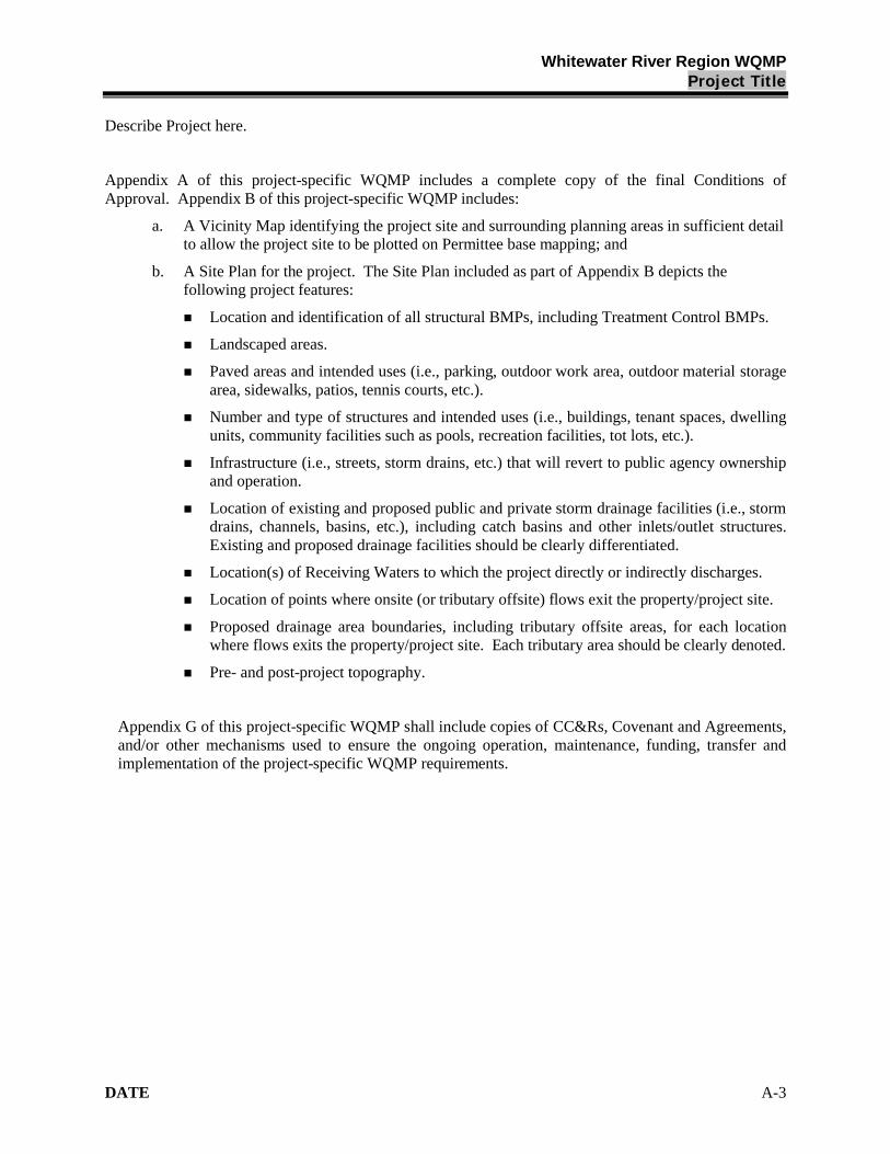
Whitewater River Region WQMPProject Title
DATE A-3
Describe Project here.
Appendix A of this project-specific WQMP includes a complete copy of the final Conditions of Approval. Appendix B of this project-specific WQMP includes:
a. A Vicinity Map identifying the project site and surrounding planning areas in sufficient detail to allow the project site to be plotted on Permittee base mapping; and
b. A Site Plan for the project. The Site Plan included as part of Appendix B depicts the following project features:
Location and identification of all structural BMPs, including Treatment Control BMPs.
Landscaped areas.
Paved areas and intended uses (i.e., parking, outdoor work area, outdoor material storage area, sidewalks, patios, tennis courts, etc.).
Number and type of structures and intended uses (i.e., buildings, tenant spaces, dwelling units, community facilities such as pools, recreation facilities, tot lots, etc.).
Infrastructure (i.e., streets, storm drains, etc.) that will revert to public agency ownership and operation.
Location of existing and proposed public and private storm drainage facilities (i.e., storm drains, channels, basins, etc.), including catch basins and other inlets/outlet structures. Existing and proposed drainage facilities should be clearly differentiated.
Location(s) of Receiving Waters to which the project directly or indirectly discharges.
Location of points where onsite (or tributary offsite) flows exit the property/project site.
Proposed drainage area boundaries, including tributary offsite areas, for each location where flows exits the property/project site. Each tributary area should be clearly denoted.
Pre- and post-project topography.
Appendix G of this project-specific WQMP shall include copies of CC&Rs, Covenant and Agreements, and/or other mechanisms used to ensure the ongoing operation, maintenance, funding, transfer and implementation of the project-specific WQMP requirements.
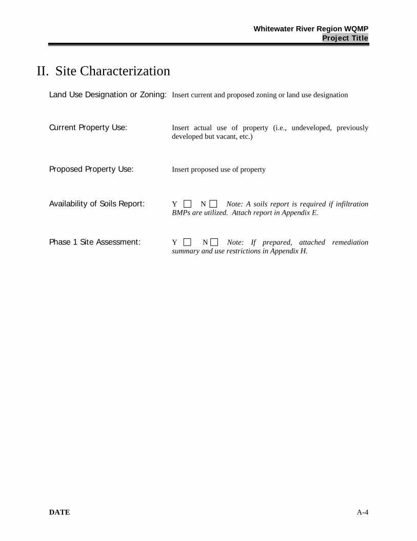
Whitewater River Region WQMPProject Title
DATE A-4
II. Site Characterization
Land Use Designation or Zoning: Insert current and proposed zoning or land use designation
Current Property Use: Insert actual use of property (i.e., undeveloped, previously developed but vacant, etc.)
Proposed Property Use: Insert proposed use of property
Availability of Soils Report: Y N Note: A soils report is required if infiltration BMPs are utilized. Attach report in Appendix E.
Phase 1 Site Assessment: Y N Note: If prepared, attached remediation summary and use restrictions in Appendix H.

Whitewater River Region WQMPProject Title
DATE A-5
Receiving Waters for Urban Runoff from Site
Instructions:
On the following page, list in order of upstream to downstream, the receiving waters that the project is tributary to. Continue to fill each row with the receiving water’s 303(d) listed impairments, designated beneficial uses, and proximity, if any, to a RARE beneficial use.
Receiving Waters for Urban Runoff from Site
Receiving Waters
303(d) List Impairments Designated Beneficial Uses
Proximity to RARE Beneficial Use
Insert name of 1st receiving water
List any 303(d) impairments of 1st receiving water, including TMDL pollutant limitations
Insert designated beneficial use of 1st receiving water
Insert distance of project to RARE-designated waters (indicate whether feet, yards, or miles)
insert name of 2nd receiving water
List any 303(d) impairments of 2nd receiving water, including TMDL pollutant limitations
Insert designated beneficial use of 2nd receiving water
Insert distance of project to RARE-designated waters (indicate whether feet, yards, or miles)
Insert name of 3rd receiving water
List any 303(d) impairments of 3rd receiving water, including TMDL pollutant limitations
Insert designated beneficial use of 3rd receiving water
Insert distance of project to RARE-designated waters (indicate whether feet, yards, or miles)
Insert Name Of 4th Receiving Water
List any 303(d) impairments of 4th receiving water, including TMDL pollutant limitations
Insert designated beneficial use of 4th receiving water
Insert distance of project to RARE-designated waters (indicate whether feet, yards, or miles)
Insert Name Of 5th Receiving Water
List any 303(d) impairments of 4th receiving water, including TMDL pollutant limitations
Insert designated beneficial use of 4th receiving water
Insert distance of project to RARE-designated waters (indicate whether feet, yards, or miles)
Insert Name Of 6th Receiving Water
List any 303(d) impairments of 4th receiving water, including TMDL pollutant limitations
Insert designated beneficial use of 4th receiving water
Insert distance of project to RARE-designated waters (indicate whether feet, yards, or miles)
Insert Name Of 7th Receiving Water
List any 303(d) impairments of 4th receiving water, including TMDL pollutant limitations
Insert designated beneficial use of 4th receiving water
Insert distance of project to RARE-designated waters (indicate whether feet, yards, or miles)
Insert Name Of 8th Receiving Water
List any 303(d) impairments of 4th receiving water, including TMDL pollutant limitations
Insert designated beneficial use of 4th receiving water
Insert distance of project to RARE-designated waters (indicate whether feet, yards, or miles)
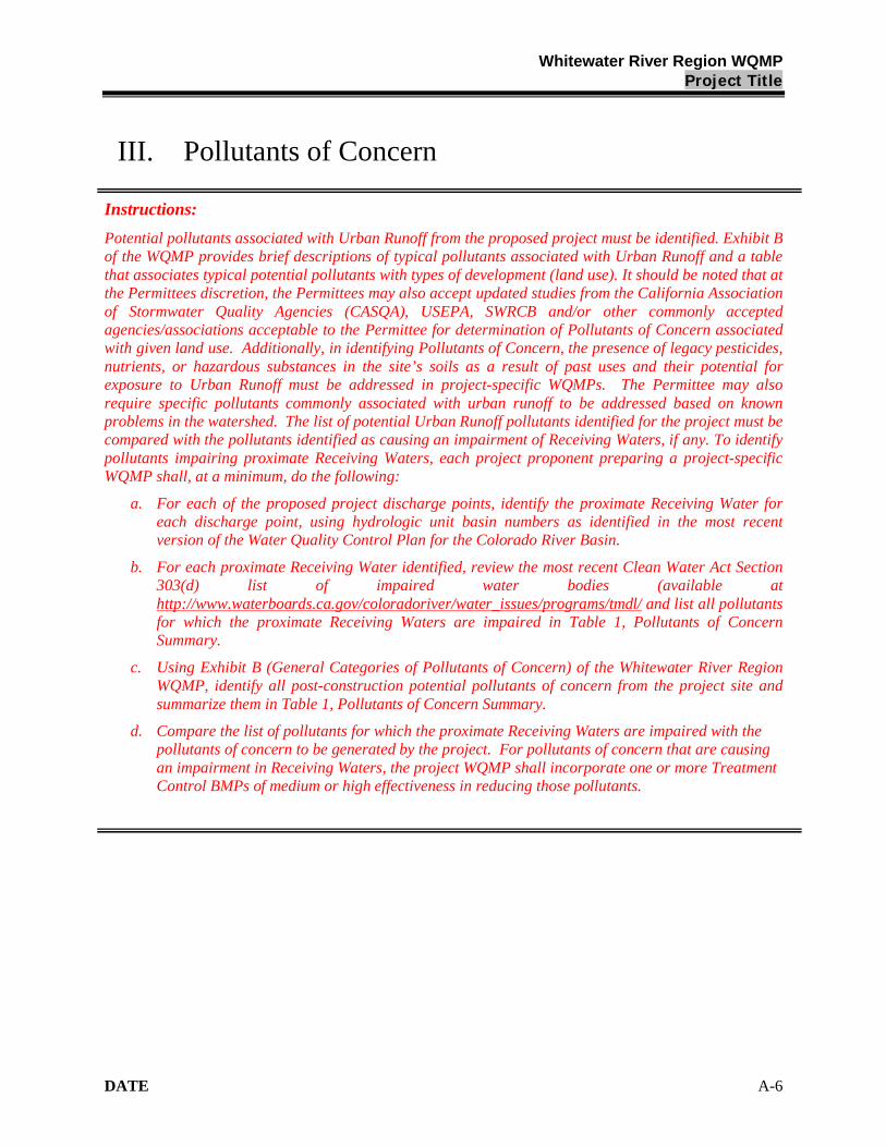
Whitewater River Region WQMPProject Title
DATE A-6
III. Pollutants of Concern
Instructions:
Potential pollutants associated with Urban Runoff from the proposed project must be identified. Exhibit B of the WQMP provides brief descriptions of typical pollutants associated with Urban Runoff and a table that associates typical potential pollutants with types of development (land use). It should be noted that at the Permittees discretion, the Permittees may also accept updated studies from the California Association of Stormwater Quality Agencies (CASQA), USEPA, SWRCB and/or other commonly accepted agencies/associations acceptable to the Permittee for determination of Pollutants of Concern associated with given land use. Additionally, in identifying Pollutants of Concern, the presence of legacy pesticides, nutrients, or hazardous substances in the site’s soils as a result of past uses and their potential for exposure to Urban Runoff must be addressed in project-specific WQMPs. The Permittee may also require specific pollutants commonly associated with urban runoff to be addressed based on known problems in the watershed. The list of potential Urban Runoff pollutants identified for the project must be compared with the pollutants identified as causing an impairment of Receiving Waters, if any. To identify pollutants impairing proximate Receiving Waters, each project proponent preparing a project-specific WQMP shall, at a minimum, do the following:
a. For each of the proposed project discharge points, identify the proximate Receiving Water for each discharge point, using hydrologic unit basin numbers as identified in the most recent version of the Water Quality Control Plan for the Colorado River Basin.
b. For each proximate Receiving Water identified, review the most recent Clean Water Act Section 303(d) list of impaired water bodies (available at http://www.waterboards.ca.gov/coloradoriver/water_issues/programs/tmdl/ and list all pollutants for which the proximate Receiving Waters are impaired in Table 1, Pollutants of Concern Summary.
c. Using Exhibit B (General Categories of Pollutants of Concern) of the Whitewater River Region WQMP, identify all post-construction potential pollutants of concern from the project site and summarize them in Table 1, Pollutants of Concern Summary.
d. Compare the list of pollutants for which the proximate Receiving Waters are impaired with the pollutants of concern to be generated by the project. For pollutants of concern that are causing an impairment in Receiving Waters, the project WQMP shall incorporate one or more Treatment Control BMPs of medium or high effectiveness in reducing those pollutants.
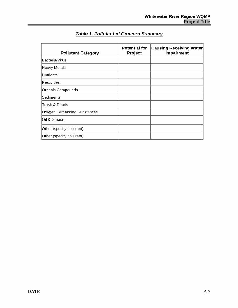
Whitewater River Region WQMPProject Title
DATE A-7
Table 1. Pollutant of Concern Summary
Pollutant CategoryPotential for
ProjectCausing Receiving Water
Impairment
Bacteria/Virus
Heavy Metals
Nutrients
Pesticides
Organic Compounds
Sediments
Trash & Debris
Oxygen Demanding Substances
Oil & Grease
Other (specify pollutant):
Other (specify pollutant):
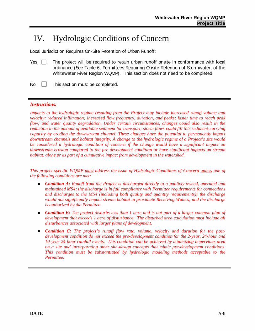
Whitewater River Region WQMPProject Title
DATE A-8
IV. Hydrologic Conditions of Concern
Local Jurisdiction Requires On-Site Retention of Urban Runoff:
Yes The project will be required to retain urban runoff onsite in conformance with local ordinance (See Table 6, Permittees Requiring Onsite Retention of Stormwater, of the Whitewater River Region WQMP). This section does not need to be completed.
No This section must be completed.
Instructions:
Impacts to the hydrologic regime resulting from the Project may include increased runoff volume and velocity; reduced infiltration; increased flow frequency, duration, and peaks; faster time to reach peak flow; and water quality degradation. Under certain circumstances, changes could also result in the reduction in the amount of available sediment for transport; storm flows could fill this sediment-carrying capacity by eroding the downstream channel. These changes have the potential to permanently impact downstream channels and habitat integrity. A change to the hydrologic regime of a Project’s site would be considered a hydrologic condition of concern if the change would have a significant impact on downstream erosion compared to the pre-development condition or have significant impacts on stream habitat, alone or as part of a cumulative impact from development in the watershed.
This project-specific WQMP must address the issue of Hydrologic Conditions of Concern unless one of the following conditions are met:
Condition A: Runoff from the Project is discharged directly to a publicly-owned, operated and maintained MS4; the discharge is in full compliance with Permittee requirements for connections and discharges to the MS4 (including both quality and quantity requirements); the discharge would not significantly impact stream habitat in proximate Receiving Waters; and the discharge is authorized by the Permittee.
Condition B: The project disturbs less than 1 acre and is not part of a larger common plan of development that exceeds 1 acre of disturbance. The disturbed area calculation must include all disturbances associated with larger plans of development.
Condition C: The project’s runoff flow rate, volume, velocity and duration for the post-development condition do not exceed the pre-development condition for the 2-year, 24-hour and 10-year 24-hour rainfall events. This condition can be achieved by minimizing impervious area on a site and incorporating other site-design concepts that mimic pre-development conditions. This condition must be substantiated by hydrologic modeling methods acceptable to the Permittee.
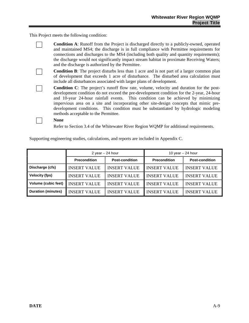
Whitewater River Region WQMPProject Title
DATE A-9
This Project meets the following condition:
Condition A: Runoff from the Project is discharged directly to a publicly-owned, operated and maintained MS4; the discharge is in full compliance with Permittee requirements for connections and discharges to the MS4 (including both quality and quantity requirements); the discharge would not significantly impact stream habitat in proximate Receiving Waters; and the discharge is authorized by the Permittee.
Condition B: The project disturbs less than 1 acre and is not part of a larger common plan of development that exceeds 1 acre of disturbance. The disturbed area calculation must include all disturbances associated with larger plans of development.
Condition C: The project’s runoff flow rate, volume, velocity and duration for the post-development condition do not exceed the pre-development condition for the 2-year, 24-hour and 10-year 24-hour rainfall events. This condition can be achieved by minimizing impervious area on a site and incorporating other site-design concepts that mimic pre-development conditions. This condition must be substantiated by hydrologic modeling methods acceptable to the Permittee.
None
Refer to Section 3.4 of the Whitewater River Region WQMP for additional requirements.
Supporting engineering studies, calculations, and reports are included in Appendix C.
2 year – 24 hour 10 year – 24 hour
Precondition Post-condition Precondition Post-condition
Discharge (cfs) INSERT VALUE INSERT VALUE INSERT VALUE INSERT VALUE
Velocity (fps) INSERT VALUE INSERT VALUE INSERT VALUE INSERT VALUE
Volume (cubic feet) INSERT VALUE INSERT VALUE INSERT VALUE INSERT VALUE
Duration (minutes) INSERT VALUE INSERT VALUE INSERT VALUE INSERT VALUE
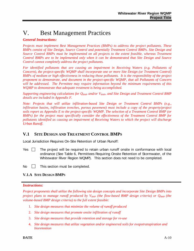
Whitewater River Region WQMPProject Title
DATE A-10
V. Best Management PracticesGeneral Instructions:
Projects must implement Best Management Practices (BMPs) to address the project pollutants. These BMPs consist of Site Design, Source Control and potentially Treatment Control BMPs. Site Design and Source Control BMPs must be implemented on all projects to the extent feasible, whereas Treatment Control BMPs are to be implemented only when it can be demonstrated that Site Design and Source Control cannot completely address the project pollutants.
For identified pollutants that are causing an impairment in Receiving Waters (e.g. Pollutants ofConcern), the project-specific WQMP shall incorporate one or more Site Design (or Treatment Control) BMPs of medium or high effectiveness in reducing those pollutants. It is the responsibility of the project proponent to demonstrate, and document in the project-specific WQMP, that all Pollutants of Concern will be addressed. The Permittee may require information beyond the minimum requirements of this WQMP to demonstrate that adequate treatment is being accomplished.
Supporting engineering calculations for QBMP and/or VBMP, and Site Design and Treatment Control BMP details are included in Appendix F.
Note: Projects that will utilize infiltration-based Site Design or Treatment Control BMPs (e.g., infiltration basins, infiltration trenches, porous pavement) must include a copy of the property/project soils report as Appendix E to the project-specific WQMP. The selection of a Treatment Control BMP (or BMPs) for the project must specifically consider the effectiveness of the Treatment Control BMP for pollutants identified as causing an impairment of Receiving Waters to which the project will discharge Urban Runoff.
V.1 SITE DESIGN AND TREATMENT CONTROL BMPS
Local Jurisdiction Requires On-Site Retention of Urban Runoff:
Yes The project will be required to retain urban runoff onsite in conformance with local ordinance (See Table 6, Permittees Requiring Onsite Retention of Stormwater, of the Whitewater River Region WQMP). This section does not need to be completed.
No This section must be completed.
V.1.A SITE DESIGN BMPS
Instructions:
Project proponents shall utilize the following site design concepts and incorporate Site Design BMPs into project plans to manage runoff produced by VBMP (the flow-based BMP design criteria) or QBMP (the volume-based BMP design criteria) to the full extent feasible:
1. Site design measures that minimize the volume of runoff produced
2. Site design measures that promote onsite infiltration of runoff
3. Site design measures that provide retention and storage for re-use
4. Site design measures that utilize vegetation and/or engineered soils for evapotranspiration and bioretention

Whitewater River Region WQMPProject Title
DATE A-11
The project proponent must complete Table 2 and indicate “Yes,” “No,” or “N/A” for each Site Design BMP. Following Table 2:
1. The project proponent must provide a narrative descriptions explaining how each includedBMP will be implemented. In those areas where Site Design BMPs require ongoing maintenance, the inspection and maintenance frequency, the inspection criteria, and the entity or party responsible for implementation, maintenance, and/or inspection shall be described. The location of each Site Design BMP must also be shown on the WQMP Site Plan included in Appendix B.
2. If a particular Site Design BMP concept is indicated as “No” or “N/A”, a brief explanation must be provided as to why the concept cannot be implemented.
If the project proponent implements a Permittee-approved alternative or equally effective Site Design BMP, an additional description indicating the nature of the Site Design BMP and how it addresses the Site Design concept shall be provided.
The project proponent must complete Table 3, Site Design BMPs Measurable Goal Summary, which summarizes the extent to which Site Design BMPs have been incorporated into project plans relative to the size of the entire project site.
Note: The Permittees general plan or other land use regulations/documents may require several measures that are effectively Site Design BMPs (such as minimization of directly connected impervious areas or setbacks from natural drainage courses). The project proponent should consult Permittee staff to determine if those requirements may be identified as Site Design BMPs. See Section 3.5.1 of the WQMP for additional guidance on Site Design BMPs.

Whitewater River Region WQMPProject Title
DATE A-12
Table 2. Site Design BMPs
IncludedDesign
ConceptTechnique Specific BMP Yes No N/A
Brief Reason for All BMPsIndicated as No or N/A
Conserve natural areas by concentrating or cluster development on the lease environmentally sensitive portions of a site while leaving the remaining land in a natural, undisturbed condition.Conserve natural areas by incorporating the goals of the Multi-Species Habitat Conservation Plan or other natural resource plans.
Preserve natural drainage features and natural depressional storage areas on the site.
Maximize canopy interception and water conservation by preserving existing native trees and shrubs, and planting additional native or drought tolerant trees and large shrubs.
Use natural drainage systems.
Increase the building floor area ratio (i.e., number of stories above or below ground).Construct streets, sidewalks and parking lot aisles to minimum widths necessary, provided that public safety and a walkable environment for pedestrians is not compromised.Reduce widths of streets where off-street parking is available.Design driveways with shared access, flared (single lane at street), or wheel strips (paving only under the tires).Minimize the use of impervious surfaces, such as decorative concrete, in the landscape design.
Sit
e D
esig
n C
on
cep
t 1
MinimizeVolumeof RunoffProduced
(See WQMP Section 3.5.1.2)
Other comparable and equally effective Site Design BMP (or BMPs) as approved by the Permittee (Note: Additional narrative required to describe BMP and how it addresses site design concept).
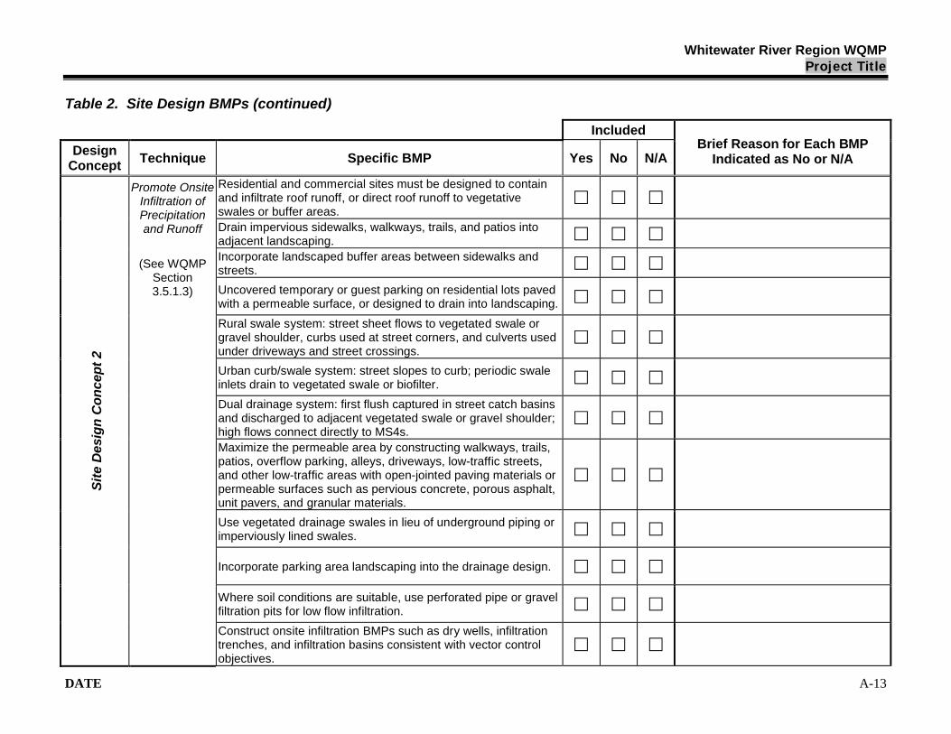
Whitewater River Region WQMPProject Title
DATE A-13
Table 2. Site Design BMPs (continued)
Included
Design Concept
Technique Specific BMP Yes No N/ABrief Reason for Each BMP
Indicated as No or N/A
Residential and commercial sites must be designed to contain and infiltrate roof runoff, or direct roof runoff to vegetative swales or buffer areas.Drain impervious sidewalks, walkways, trails, and patios into adjacent landscaping.Incorporate landscaped buffer areas between sidewalks and streets.
Uncovered temporary or guest parking on residential lots paved with a permeable surface, or designed to drain into landscaping.
Rural swale system: street sheet flows to vegetated swale or gravel shoulder, curbs used at street corners, and culverts used under driveways and street crossings.
Urban curb/swale system: street slopes to curb; periodic swale inlets drain to vegetated swale or biofilter.
Dual drainage system: first flush captured in street catch basins and discharged to adjacent vegetated swale or gravel shoulder; high flows connect directly to MS4s.Maximize the permeable area by constructing walkways, trails, patios, overflow parking, alleys, driveways, low-traffic streets, and other low-traffic areas with open-jointed paving materials or permeable surfaces such as pervious concrete, porous asphalt, unit pavers, and granular materials.
Use vegetated drainage swales in lieu of underground piping or imperviously lined swales.
Incorporate parking area landscaping into the drainage design.
Where soil conditions are suitable, use perforated pipe or gravel filtration pits for low flow infiltration.
Sit
e D
esig
n C
on
cep
t 2
Promote OnsiteInfiltration ofPrecipitationand Runoff
(See WQMP Section 3.5.1.3)
Construct onsite infiltration BMPs such as dry wells, infiltration trenches, and infiltration basins consistent with vector control objectives.
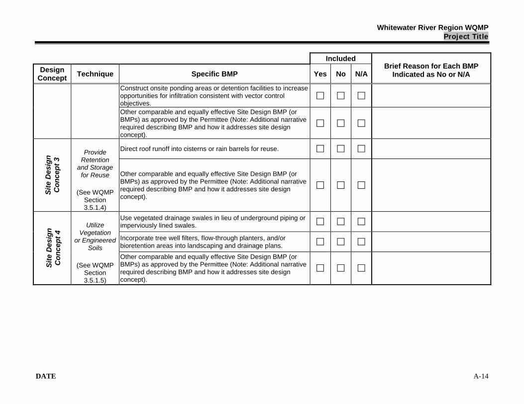
Whitewater River Region WQMPProject Title
DATE A-14
Included
Design Concept
Technique Specific BMP Yes No N/ABrief Reason for Each BMP
Indicated as No or N/A
Construct onsite ponding areas or detention facilities to increase opportunities for infiltration consistent with vector control objectives.Other comparable and equally effective Site Design BMP (or BMPs) as approved by the Permittee (Note: Additional narrative required describing BMP and how it addresses site design concept).
Direct roof runoff into cisterns or rain barrels for reuse.
Sit
e D
esig
n
Co
nce
pt
3
ProvideRetention
and Storagefor Reuse
(See WQMP Section 3.5.1.4)
Other comparable and equally effective Site Design BMP (or BMPs) as approved by the Permittee (Note: Additional narrative required describing BMP and how it addresses site design concept).
Use vegetated drainage swales in lieu of underground piping or imperviously lined swales.
Incorporate tree well filters, flow-through planters, and/or bioretention areas into landscaping and drainage plans.
Sit
e D
esig
n
Co
nce
pt
4
Utilize Vegetation
or Engineered Soils
(See WQMP Section 3.5.1.5)
Other comparable and equally effective Site Design BMP (or BMPs) as approved by the Permittee (Note: Additional narrative required describing BMP and how it addresses site design concept).

Whitewater River Region WQMPProject Title
DATE A-15
Project Site Design BMPs:
Insert text here describing how each included Site Design BMP will be implemented.

Whitewater River Region WQMPProject Title
DATE A-16
Table 3. Site Design BMPs Measurable Goal Summary
Site Design BMP
Site Design BMP Sizing
(QBMP or VBMP)
Drainage SubareaID or No.
Site Design BMPTributary Area
(nearest 0.1 acre)
Total of Site Design BMP Tributary Areas (nearest 0.1 acre)
Total Project Site Area (nearest 0.1 acre)
Achievement of Site Design BMPs Measurable Goal:
Insert text here describing the constraints that prevent the QBMP or VBMP for the entire project site from being managed with Site Design BMPs.
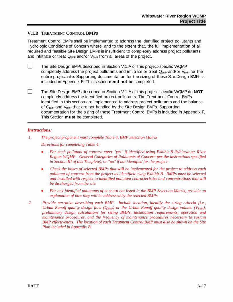
Whitewater River Region WQMPProject Title
DATE A-17
V.1.B TREATMENT CONTROL BMPS
Treatment Control BMPs shall be implemented to address the identified project pollutants and Hydrologic Conditions of Concern where, and to the extent that, the full implementation of all required and feasible Site Design BMPs is insufficient to completely address project pollutants and infiltrate or treat QBMP and/or VBMP from all areas of the project.
The Site Design BMPs described in Section V.1.A of this project-specific WQMP completely address the project pollutants and infiltrate or treat QBMP and/or VBMP for the entire project site. Supporting documentation for the sizing of these Site Design BMPs is included in Appendix F. This section need not be completed.
The Site Design BMPs described in Section V.1.A of this project-specific WQMP do NOTcompletely address the identified project pollutants. The Treatment Control BMPs identified in this section are implemented to address project pollutants and the balance of QBMP and VBMP that are not handled by the Site Design BMPs. Supporting documentation for the sizing of these Treatment Control BMPs is included in Appendix F. This Section must be completed.
Instructions:
1. The project proponent must complete Table 4, BMP Selection Matrix
Directions for completing Table 4:
For each pollutant of concern enter "yes" if identified using Exhibit B (Whitewater River Region WQMP - General Categories of Pollutants of Concern per the instructions specified in Section III of this Template), or "no" if not identified for the project.
Check the boxes of selected BMPs that will be implemented for the project to address each pollutant of concern from the project as identified using Exhibit B. BMPs must be selected and installed with respect to identified pollutant characteristics and concentrations that will be discharged from the site.
For any identified pollutants of concern not listed in the BMP Selection Matrix, provide an explanation of how they will be addressed by the selected BMPs.
2. Provide narrative describing each BMP. Include location, identify the sizing criteria [i.e., Urban Runoff quality design flow (QBMP) or the Urban Runoff quality design volume (VBMP), preliminary design calculations for sizing BMPs, installation requirements, operation and maintenance procedures, and the frequency of maintenance procedures necessary to sustain BMP effectiveness. The location of each Treatment Control BMP must also be shown on the Site Plan included in Appendix B.
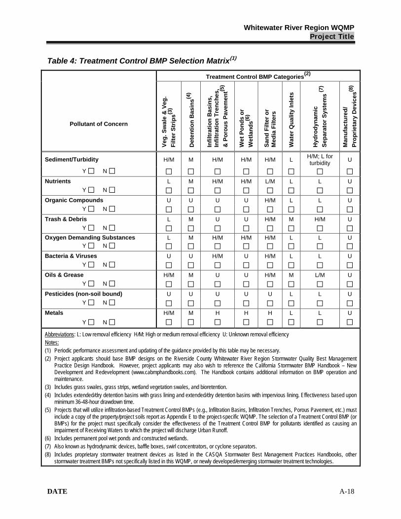
Whitewater River Region WQMPProject Title
DATE A-18
Table 4: Treatment Control BMP Selection Matrix(1)
Treatment Control BMP Categories(2)
Pollutant of Concern
Ve
g.
Sw
ale
& V
eg
.
Fil
ter
Str
ips
(3)
De
ten
tio
n B
asin
s(4
)
Infi
ltra
tio
n B
as
ins
, In
filt
rati
on
Tre
nc
he
s,
& P
oro
us
Pa
vem
en
t(5)
We
t P
on
ds
or
We
tla
nd
s(6
)
Sa
nd
Fil
ter
or
Me
dia
Fil
ters
Wa
ter
Qu
ali
ty I
nle
ts
Hy
dro
dy
nam
ic
Se
pa
rato
r S
yste
ms
(7)
Ma
nu
fac
ture
d/
Pro
pri
eta
ry D
evi
ce
s(8
)
Sediment/Turbidity H/M M H/M H/M H/M LH/M; L for turbidity
U
Y N
Nutrients L M H/M H/M L/M L L U
Y N
Organic Compounds U U U U H/M L L U
Y N
Trash & Debris L M U U H/M M H/M U
Y N
Oxygen Demanding Substances L M H/M H/M H/M L L UY N
Bacteria & Viruses U U H/M U H/M L L U
Y N
Oils & Grease H/M M U U H/M M L/M U
Y N
Pesticides (non-soil bound) U U U U U L L U
Y N
Metals H/M M H H H L L U
Y N
Abbreviations: L: Low removal efficiency H/M: High or medium removal efficiency U: Unknown removal efficiencyNotes:(1) Periodic performance assessment and updating of the guidance provided by this table may be necessary.(2) Project applicants should base BMP designs on the Riverside County Whitewater River Region Stormwater Quality Best Management
Practice Design Handbook. However, project applicants may also wish to reference the California Stormwater BMP Handbook – New Development and Redevelopment (www.cabmphandbooks.com). The Handbook contains additional information on BMP operation and maintenance.
(3) Includes grass swales, grass strips, wetland vegetation swales, and bioretention.(4) Includes extended/dry detention basins with grass lining and extended/dry detention basins with impervious lining. Effectiveness based upon
minimum 36-48-hour drawdown time. (5) Projects that will utilize infiltration-based Treatment Control BMPs (e.g., Infiltration Basins, Infiltration Trenches, Porous Pavement, etc.) must
include a copy of the property/project soils report as Appendix E to the project-specific WQMP. The selection of a Treatment Control BMP (or BMPs) for the project must specifically consider the effectiveness of the Treatment Control BMP for pollutants identified as causing an impairment of Receiving Waters to which the project will discharge Urban Runoff.
(6) Includes permanent pool wet ponds and constructed wetlands.(7) Also known as hydrodynamic devices, baffle boxes, swirl concentrators, or cyclone separators.(8) Includes proprietary stormwater treatment devices as listed in the CASQA Stormwater Best Management Practices Handbooks, other
stormwater treatment BMPs not specifically listed in this WQMP, or newly developed/emerging stormwater treatment technologies.

Whitewater River Region WQMPProject Title
DATE A-19
Insert text describing Treatment Control BMPs including all information identified in the instructions.

Whitewater River Region WQMPProject Title
DATE A-20
V.2 SOURCE CONTROL BMPS
Instructions:
Complete Table 5.
Table 5. Source Control BMPs
Check OneBMP Name
Included Not Applicable
If not applicable, state brief reason
Non-Structural Source Control BMPs
Education for Property Owners, Operators, Tenants, Occupants, or Employees
Activity Restrictions
Irrigation System and Landscape Maintenance
Common Area Litter Control
Street Sweeping Private Streets and Parking Lots
Drainage Facility Inspection and Maintenance
Structural Source Control BMPs
MS4 Stenciling and Signage
Landscape and Irrigation System Design
Protect Slopes and Channels
Provide Community Car Wash Racks
Properly Design:
Fueling Areas
Air/Water Supply Area Drainage
Trash Storage Areas
Loading Docks
Maintenance Bays
Vehicle and Equipment Wash Areas
Outdoor Material Storage Areas
Outdoor Work Areas or Processing Areas
Provide Wash Water Controls for Food Preparation Areas

Whitewater River Region WQMPProject Title
DATE A-21
Instructions:
Provide narrative below describing how each included Source Control BMP will be implemented, the implementation frequency, inspection and maintenance frequency, inspection criteria, and the entity or party responsible for implementation, maintenance, and/or inspection. The location of each structural BMP must also be shown on the WQMP Site Plan included in Appendix B.
Insert text here as instructed above.
Appendix D includes copies of the educational materials that will be used in implementing this project-specific WQMP.
Whitewater River Region WQMPProject Title
DATE A-22
V.3 EQUIVALENT TREATMENT CONTROL ALTERNATIVES
Insert Text or state "Not applicable." Note: The WQMP Preparer should refer to Section 3.5.3 of the Whitewater River Region WQMP.
V.4 REGIONALLY-BASED TREATMENT CONTROL BMPS
Insert Text or state "Not applicable." Note: The WQMP Preparer should refer to Section 4.0 of the Whitewater River Region WQMP.

Whitewater River Region WQMPProject Title
DATE A-23
VI. Operation and Maintenance Responsibility for BMPs
Instructions:Operation and maintenance (O&M) requirements for all structural Site Design, Source Control and Treatment Control BMPs shall be identified in the project-specific WQMP. The project-specific WQMP shall address the following:
Identification of each BMP that requires O&M.
Thorough description of O&M activities, the O&M process, and the handling and placement of any wastes.
BMP start-up dates.
Schedule of the frequency of O&M for each BMP.
Identification of the parties (name, address, and telephone number) responsible for O&M, including a written agreement with the entities responsible for O&M. This agreement can take the form of a Covenant and Agreement recorded by the Project Proponent with the County Recorder, HOA or POA CC&Rs, formation of a maintenance district or assessment district or other instrument sufficient to guarantee perpetual O&M. The preparer of this project-specific WQMP should carefully review Section 3.6 of the WQMP prior to completing this section of the project-specific WQMP.
Self-inspections and record-keeping requirements for BMPs (review local specific requirements regarding self-inspections and/or annual reporting), including identification of responsible parties for inspection and record- keeping.
Thorough descriptions of water quality monitoring, if required by the Permittee.
Identify below all operations and maintenance requirements, as described above, for each structural BMP. Where a public agency is identified as the funding source and responsible party for a BMP, a copy of the written agreement stating the public agency’s acceptance of these responsibilities must be provided in Appendix G.
Insert text as instructed above.
Whitewater River Region WQMPProject Title
DATE A-24
VII. Funding
Instructions:
A funding source or sources for the O&M of each Site Design and Treatment Control BMP identified in the project-specific WQMP must be identified. By certifying the project-specific WQMP, the Project applicant is certifying that the funding responsibilities have been addressed and will be transferred to future owners. One example of how to adhere to the requirement to transfer O&M responsibilities is to record the project-specific WQMP against the title to the property.
Insert text identifying the funding source or sources for the operation and maintenance of each Site Design and Treatment Control BMP included in the project.

Whitewater River Region WQMPProject Title
Appendix A
Conditions of Approval
Planning Commission Resolution
Dated

Whitewater River Region WQMPProject Title
Appendix B
Vicinity Map, WQMP Site Plan, and Receiving Waters Map

Whitewater River Region WQMPProject Title
Appendix CSupporting Detail Related to Hydraulic Conditions of Concern

Whitewater River Region WQMPProject Title
Appendix DEducational Materials

Whitewater River Region WQMPProject Title
Appendix ESoils Report

Whitewater River Region WQMPProject Title
Appendix FSite Design and Treatment Control BMP Sizing Calculations
and Design Details
Whitewater River Region WQMPProject Title
Appendix GAGREEMENTS – CC&RS, COVENANT AND AGREEMENTS AND/OR
OTHER MECHANISMS FOR ENSURING ONGOING
OPERATION, MAINTENANCE, FUNDING AND TRANSFER
OF REQUIREMENTS FOR THIS PROJECT-SPECIFIC
WQMP

Whitewater River Region WQMPProject Title
Appendix HPHASE 1 ENVIRONMENTAL SITE ASSESSMENT – SUMMARY OF SITE
REMEDIATION CONDUCTED AND USE RESTRICTIONS

Whitewater River Region WQMP Public Review Draft
April 2009
Exhibit B
General Categories of Pollutants of Concern
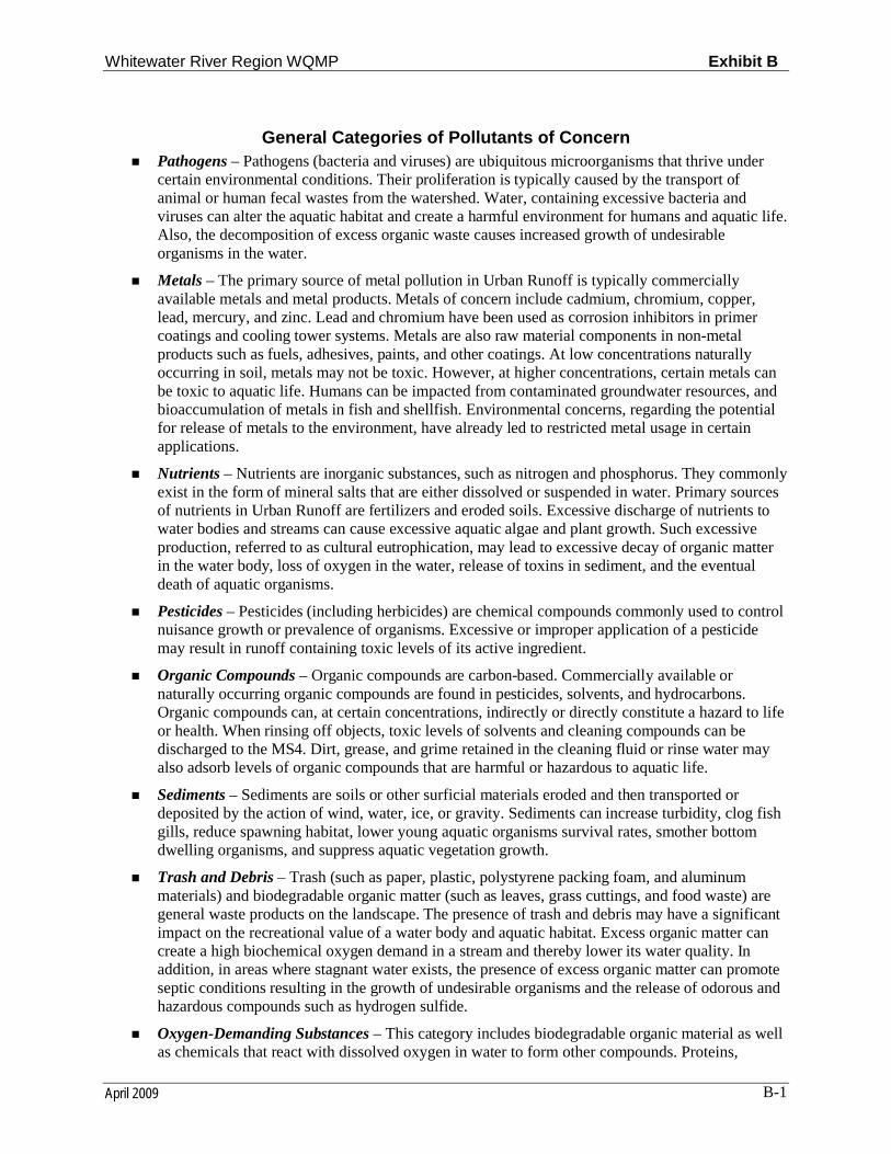
Whitewater River Region WQMP Exhibit B
April 2009 B-1
General Categories of Pollutants of Concern Pathogens – Pathogens (bacteria and viruses) are ubiquitous microorganisms that thrive under
certain environmental conditions. Their proliferation is typically caused by the transport of animal or human fecal wastes from the watershed. Water, containing excessive bacteria and viruses can alter the aquatic habitat and create a harmful environment for humans and aquatic life. Also, the decomposition of excess organic waste causes increased growth of undesirable organisms in the water.
Metals – The primary source of metal pollution in Urban Runoff is typically commercially available metals and metal products. Metals of concern include cadmium, chromium, copper, lead, mercury, and zinc. Lead and chromium have been used as corrosion inhibitors in primer coatings and cooling tower systems. Metals are also raw material components in non-metal products such as fuels, adhesives, paints, and other coatings. At low concentrations naturally occurring in soil, metals may not be toxic. However, at higher concentrations, certain metals can be toxic to aquatic life. Humans can be impacted from contaminated groundwater resources, and bioaccumulation of metals in fish and shellfish. Environmental concerns, regarding the potential for release of metals to the environment, have already led to restricted metal usage in certain applications.
Nutrients – Nutrients are inorganic substances, such as nitrogen and phosphorus. They commonly exist in the form of mineral salts that are either dissolved or suspended in water. Primary sources of nutrients in Urban Runoff are fertilizers and eroded soils. Excessive discharge of nutrients to water bodies and streams can cause excessive aquatic algae and plant growth. Such excessive production, referred to as cultural eutrophication, may lead to excessive decay of organic matter in the water body, loss of oxygen in the water, release of toxins in sediment, and the eventual death of aquatic organisms.
Pesticides – Pesticides (including herbicides) are chemical compounds commonly used to control nuisance growth or prevalence of organisms. Excessive or improper application of a pesticide may result in runoff containing toxic levels of its active ingredient.
Organic Compounds – Organic compounds are carbon-based. Commercially available or naturally occurring organic compounds are found in pesticides, solvents, and hydrocarbons. Organic compounds can, at certain concentrations, indirectly or directly constitute a hazard to life or health. When rinsing off objects, toxic levels of solvents and cleaning compounds can be discharged to the MS4. Dirt, grease, and grime retained in the cleaning fluid or rinse water may also adsorb levels of organic compounds that are harmful or hazardous to aquatic life.
Sediments – Sediments are soils or other surficial materials eroded and then transported or deposited by the action of wind, water, ice, or gravity. Sediments can increase turbidity, clog fish gills, reduce spawning habitat, lower young aquatic organisms survival rates, smother bottom dwelling organisms, and suppress aquatic vegetation growth.
Trash and Debris – Trash (such as paper, plastic, polystyrene packing foam, and aluminum materials) and biodegradable organic matter (such as leaves, grass cuttings, and food waste) are general waste products on the landscape. The presence of trash and debris may have a significant impact on the recreational value of a water body and aquatic habitat. Excess organic matter can create a high biochemical oxygen demand in a stream and thereby lower its water quality. In addition, in areas where stagnant water exists, the presence of excess organic matter can promote septic conditions resulting in the growth of undesirable organisms and the release of odorous and hazardous compounds such as hydrogen sulfide.
Oxygen-Demanding Substances – This category includes biodegradable organic material as well as chemicals that react with dissolved oxygen in water to form other compounds. Proteins,
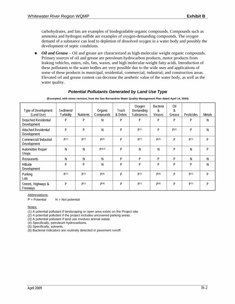
Whitewater River Region WQMP Exhibit B
April 2009 B-2
carbohydrates, and fats are examples of biodegradable organic compounds. Compounds such as ammonia and hydrogen sulfide are examples of oxygen-demanding compounds. The oxygen demand of a substance can lead to depletion of dissolved oxygen in a water body and possibly the development of septic conditions.
Oil and Grease – Oil and grease are characterized as high-molecular weight organic compounds. Primary sources of oil and grease are petroleum hydrocarbon products, motor products from leaking vehicles, esters, oils, fats, waxes, and high molecular-weight fatty acids. Introduction of these pollutants to the water bodies are very possible due to the wide uses and applications of some of these products in municipal, residential, commercial, industrial, and construction areas. Elevated oil and grease content can decrease the aesthetic value of the water body, as well as the water quality.
Potential Pollutants Generated by Land Use Type
(Excerpted, with minor revision, from the San Bernardino Water Quality Management Plan dated April 14, 2004)
Type of Development (Land Use)
Sediment/Turbidity Nutrients
OrganicCompounds
Trash& Debris
OxygenDemandingSubstances
Bacteria &
Viruses
Oil&
Grease Pesticides Metals
Detached Residential Development
P P N P P P P P N
Attached Residential Development
P P N P P(1) P P(2) P N
Commercial/ Industrial Development
P(1) P(1) P(5) P P(1) P(3) P P(1) P
Automotive Repair Shops
N N P(4,5) P N N P N P
Restaurants N N N P P P P N N
HillsideDevelopment
P P N P P P P P N
ParkingLots
P(1) P(1) P(4) P P(1) P(6) P P(1) P
Streets, Highways & Freeways
P P(1) P(4) P P(1) P(6) P P(1) P
Abbreviations:P = Potential N = Not potential
Notes:(1) A potential pollutant if landscaping or open area exists on the Project site.(2) A potential pollutant if the project includes uncovered parking areas.(3) A potential pollutant if land use involves animal waste.(4) Specifically, petroleum hydrocarbons.(5) Specifically, solvents.(6) Bacterial indicators are routinely detected in pavement runoff.
Whitewater River Region WQMP Public Review Draft
April 2009
Exhibit C
Riverside County Whitewater River RegionStormwater Quality Best Management Practice
Design Handbook
Riverside County
Whitewater River Region
Stormwater Quality Best Management Practice
Design Handbook
Riverside County Flood Control and Water Conservation District
1995 Market Street
Riverside CA 92501
April 2009
Riverside County - Whitewater River Region Water Quality Management Plan Exhibit C
ii
TABLE OF CONTENTS
BMP Design Criteria .............................................................................................................................. 1 Introduction ....................................................................................................................................... 1 BMP Selection ................................................................................................................................... 2
Volume Based BMPs .............................................................................................................................. 4 BMP Design Volume Calculations .................................................................................................... 4
Worksheet 1 ............................................................................................................................... 6 Flow Based BMPs ................................................................................................................................... 7
Uniform Intensity Approach .............................................................................................................. 7 Worksheet 2 ............................................................................................................................... 9
Extended Detention Basins .................................................................................................................. 10 Extended Detention Basin Design Procedure .................................................................................. 11
Worksheet 3 ............................................................................................................................. 18 Infiltration Basins ................................................................................................................................. 21
Infiltration Basin Design Procedure ................................................................................................ 22 Worksheet 4 ............................................................................................................................. 25
Infiltration Trenches ............................................................................................................................ 26 Infiltration Trench Design Procedure .............................................................................................. 27
Worksheet 5 ............................................................................................................................. 29 Porous Pavement .................................................................................................................................. 30
Porous Pavement Design Procedure ................................................................................................ 31 Worksheet 6 ............................................................................................................................. 33
Sand Filters ............................................................................................................................................ 34 Austin Sand Filter ............................................................................................................................ 34 Austin Sand Filter Design Procedure .............................................................................................. 36
Worksheet 7 ............................................................................................................................. 42 Delaware Sand Filter ............................................................................................................................ 44
Delaware Sand Filter Design Procedure .......................................................................................... 45 Worksheet 8 ............................................................................................................................. 49
Grassed Swales ...................................................................................................................................... 51 Grass Swale Design Procedure ........................................................................................................ 52
Worksheet 9 ............................................................................................................................. 54 Filter Strips ............................................................................................................................................ 55
Filter Strip Design Procedure .......................................................................................................... 56 Worksheet 10 ........................................................................................................................... 58
Water Quality Inlets ............................................................................................................................. 59 Water Quailty Inlet Design Procedure ............................................................................................. 59
Worksheet 11 ........................................................................................................................... 60 REFERENCES ..................................................................................................................................... 61 APPENDIX A ........................................................................................................................................ 62
BMP Design Examples .................................................................................................................... 62
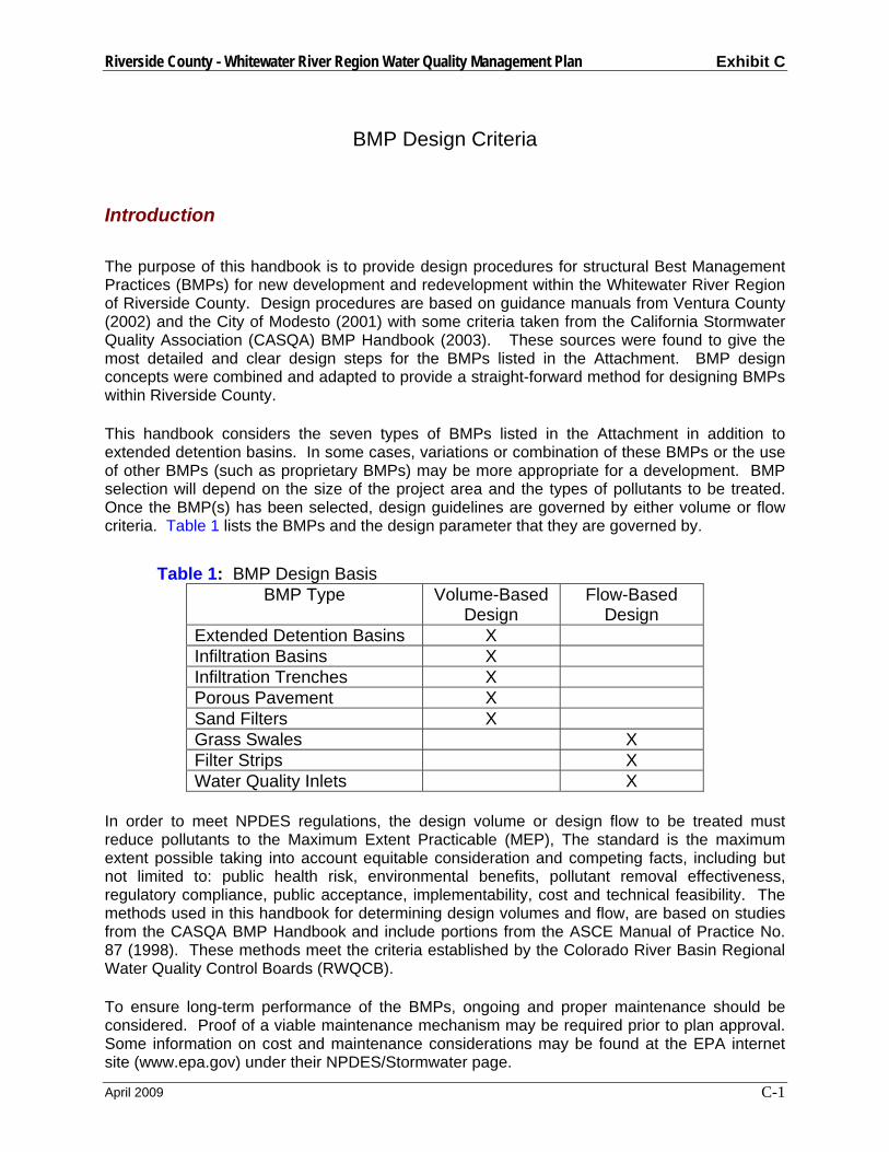
Riverside County - Whitewater River Region Water Quality Management Plan Exhibit C
April 2009 C-1
BMP Design Criteria
Introduction
The purpose of this handbook is to provide design procedures for structural Best Management Practices (BMPs) for new development and redevelopment within the Whitewater River Region of Riverside County. Design procedures are based on guidance manuals from Ventura County (2002) and the City of Modesto (2001) with some criteria taken from the California Stormwater Quality Association (CASQA) BMP Handbook (2003). These sources were found to give the most detailed and clear design steps for the BMPs listed in the Attachment. BMP design concepts were combined and adapted to provide a straight-forward method for designing BMPs within Riverside County. This handbook considers the seven types of BMPs listed in the Attachment in addition to extended detention basins. In some cases, variations or combination of these BMPs or the use of other BMPs (such as proprietary BMPs) may be more appropriate for a development. BMP selection will depend on the size of the project area and the types of pollutants to be treated. Once the BMP(s) has been selected, design guidelines are governed by either volume or flow criteria. Table 1 lists the BMPs and the design parameter that they are governed by.
Table 1: BMP Design Basis
BMP Type Volume-Based Design
Flow-Based Design
Extended Detention Basins X Infiltration Basins X Infiltration Trenches X Porous Pavement X Sand Filters X Grass Swales X Filter Strips X Water Quality Inlets X
In order to meet NPDES regulations, the design volume or design flow to be treated must reduce pollutants to the Maximum Extent Practicable (MEP), The standard is the maximum extent possible taking into account equitable consideration and competing facts, including but not limited to: public health risk, environmental benefits, pollutant removal effectiveness, regulatory compliance, public acceptance, implementability, cost and technical feasibility. The methods used in this handbook for determining design volumes and flow, are based on studies from the CASQA BMP Handbook and include portions from the ASCE Manual of Practice No. 87 (1998). These methods meet the criteria established by the Colorado River Basin Regional Water Quality Control Boards (RWQCB). To ensure long-term performance of the BMPs, ongoing and proper maintenance should be considered. Proof of a viable maintenance mechanism may be required prior to plan approval. Some information on cost and maintenance considerations may be found at the EPA internet site (www.epa.gov) under their NPDES/Stormwater page.

Riverside County - Whitewater River Region Water Quality Management Plan Exhibit C
April 2009 C-2
BMP Selection Different types of development result in different types of stormwater pollution. Most BMPs only treat some of these pollutants. To effectively protect water quality, the BMP(s) selected for a project must treat each of the project’s identified pollutants. Table 2 identifies potential pollutants based on the type of development proposed. Table 3 can be used to select BMPs to treat these pollutants.
Table 2: Potential Pollutants Generated by Land Use Type (Excerpted, with minor revision, from the San Bernardino Water Quality Management Plan dated April 14, 2004)
Type of Development
(Land Use)
Sediment/Turbidity
Nutrients
Organic
Compounds
Trash
& Debris
Oxygen Demanding Substances
Bacteria &
Viruses
Oil &
Grease
Pesticides
Metals Detached Residential Development
P P N P P P P P N
Attached Residential Development
P P N P P(1) P P(2) P N
Commercial/ Industrial Development
P(1) P(1) P(5) P P(1) P(3) P P(1) P
Automotive Repair Shops
N N P(4,5) P N N P N P
Restaurants N N N P P P P N N Hillside Development
P P N P P P P P N
Parking Lots
P(1) P(1) P(4) P P(1) P(6) P P(1) P
Streets, Highways & Freeways
P P(1) P(4) P P(1) P(6) P P(1) P
Abbreviations: P = Potential N = Not potential Notes: (1) A potential pollutant if landscaping or open area exists on the Project site. (2) A potential pollutant if the project includes uncovered parking areas. (3) A potential pollutant if land use involves animal waste. (4) Specifically, petroleum hydrocarbons. (5) Specifically, solvents. (6) Bacterial indicators are routinely detected in pavement runoff.
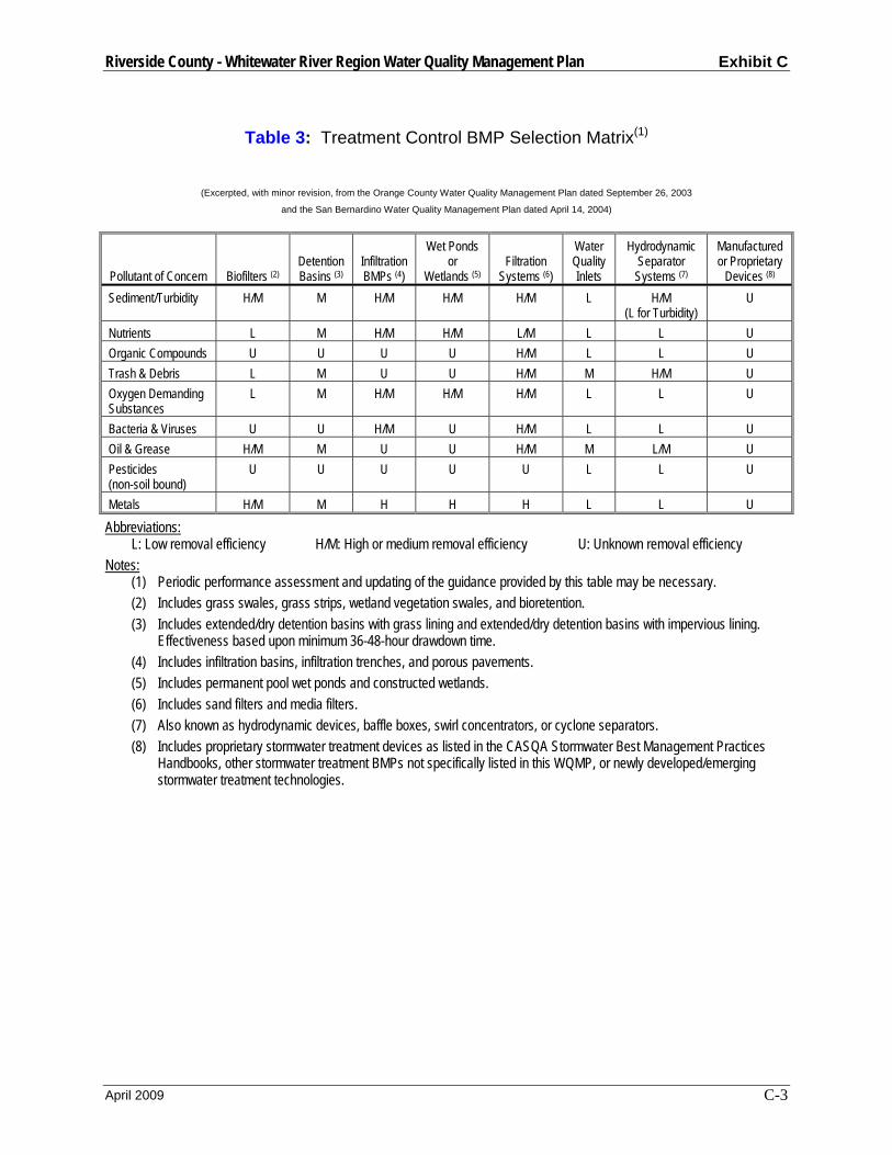
Riverside County - Whitewater River Region Water Quality Management Plan Exhibit C
April 2009 C-3
Table 3: Treatment Control BMP Selection Matrix(1)
(Excerpted, with minor revision, from the Orange County Water Quality Management Plan dated September 26, 2003
and the San Bernardino Water Quality Management Plan dated April 14, 2004)
Pollutant of Concern
Biofilters (2)
Detention Basins (3)
Infiltration BMPs (4)
Wet Ponds or
Wetlands (5)
Filtration
Systems (6)
Water Quality Inlets
Hydrodynamic Separator Systems (7)
Manufactured or Proprietary
Devices (8) Sediment/Turbidity H/M M H/M H/M H/M L H/M
(L for Turbidity) U
Nutrients L M H/M H/M L/M L L U Organic Compounds U U U U H/M L L U Trash & Debris L M U U H/M M H/M U Oxygen Demanding Substances
L M H/M H/M H/M L L U
Bacteria & Viruses U U H/M U H/M L L U Oil & Grease H/M M U U H/M M L/M U Pesticides (non-soil bound)
U U U U U L L U
Metals H/M M H H H L L U
Abbreviations: L: Low removal efficiency H/M: High or medium removal efficiency U: Unknown removal efficiency
Notes: (1) Periodic performance assessment and updating of the guidance provided by this table may be necessary. (2) Includes grass swales, grass strips, wetland vegetation swales, and bioretention. (3) Includes extended/dry detention basins with grass lining and extended/dry detention basins with impervious lining.
Effectiveness based upon minimum 36-48-hour drawdown time. (4) Includes infiltration basins, infiltration trenches, and porous pavements. (5) Includes permanent pool wet ponds and constructed wetlands. (6) Includes sand filters and media filters. (7) Also known as hydrodynamic devices, baffle boxes, swirl concentrators, or cyclone separators. (8) Includes proprietary stormwater treatment devices as listed in the CASQA Stormwater Best Management Practices
Handbooks, other stormwater treatment BMPs not specifically listed in this WQMP, or newly developed/emerging stormwater treatment technologies.
Riverside County - Whitewater River Region Water Quality Management Plan Exhibit C
April 2009 C-4
Volume Based BMPs
General The largest concentrations of pollutants are found in runoff from small volume storms and from the first flush of larger storms. Therefore, volume based BMPs should be sized to capture and treat the initial and more frequent runoff surges that convey the greatest concentration of pollutants. To maximize treatment and avoid health hazards, volume-based BMPs must retain and release the runoff between a 24 and 72 hour period. This handbook typically recommends a draw down time of 48 hours, as recommended by the California BMP Handbook. The drawdown time refers to the minimum amount of time the design volume must be retained. In order to meet RWQCB requirements, Volume-based Treatment Control BMPs in the Whitewater River Region of Riverside County shall be designed to infiltrate or treat the volume of runoff, VBMP calculated using the following procedure, developed using the CASQA Methodology referenced in Section F.1.b.4.a.ii of the Permit.
BMP Design Volume Calculations
Following is a step-by-step procedure for determining design volume for BMPs using
Worksheet 1.
1. Determine the BMP Tributary Area (Atrib) that drains to the proposed BMP. This includes all areas that will contribute runoff to the proposed BMP, including both pervious and impervious areas, and runoff from off-site areas that commingle with site runoff, whether or not they are directly or indirectly connected to the BMP. Measure this area in acres.
2. Determine the impervious area ratio (i) within the tributary area defined above. i=Aimp/Atrib, where
Aimp = the impervious area within Atrib, measured in acres.
3. Calculate the composite Runoff Coefficient (C) for the BMP Tributary Area using Figure 1 below or the following equation based on the WEF/ASCE Method:
C = 0.858i3 – 0.78i2 + 0.774i + 0.04, where
i = the impervious area ratio defined above.
4. Determine the Unit Storage Volume (Vu) using the following equation derived from the Palm Springs Thermal Airport gauge data in Appendix D of the CASQA BMP Handbook:
CVu ×= 40.0 , where
Vu = the unit storage volume (acre-in/acre), and C is the composite runoff coefficient calculated in the previous step.
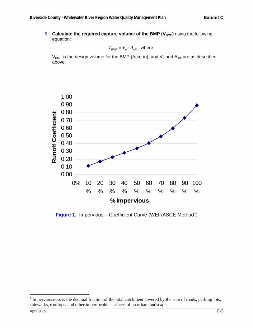
Riverside County - Whitewater River Region Water Quality Management Plan Exhibit C
April 2009 C-5
5. Calculate the required capture volume of the BMP (VBMP) using the following equation:
tribuBMP AVV ⋅= , where
VBMP is the design volume for the BMP (Acre-in), and Vu and Atrib are as described above.
Figure 1. Impervious – Coefficient Curve (WEF/ASCE Method1)
1 Imperviousness is the decimal fraction of the total catchment covered by the sum of roads, parking lots, sidewalks, rooftops, and other impermeable surfaces of an urban landscape.
0.000.100.200.300.400.500.600.700.800.901.00
0% 10%
20%
30%
40%
50%
60%
70%
80%
90%
100%
% Impervious
Run
off C
oeffi
cien
t
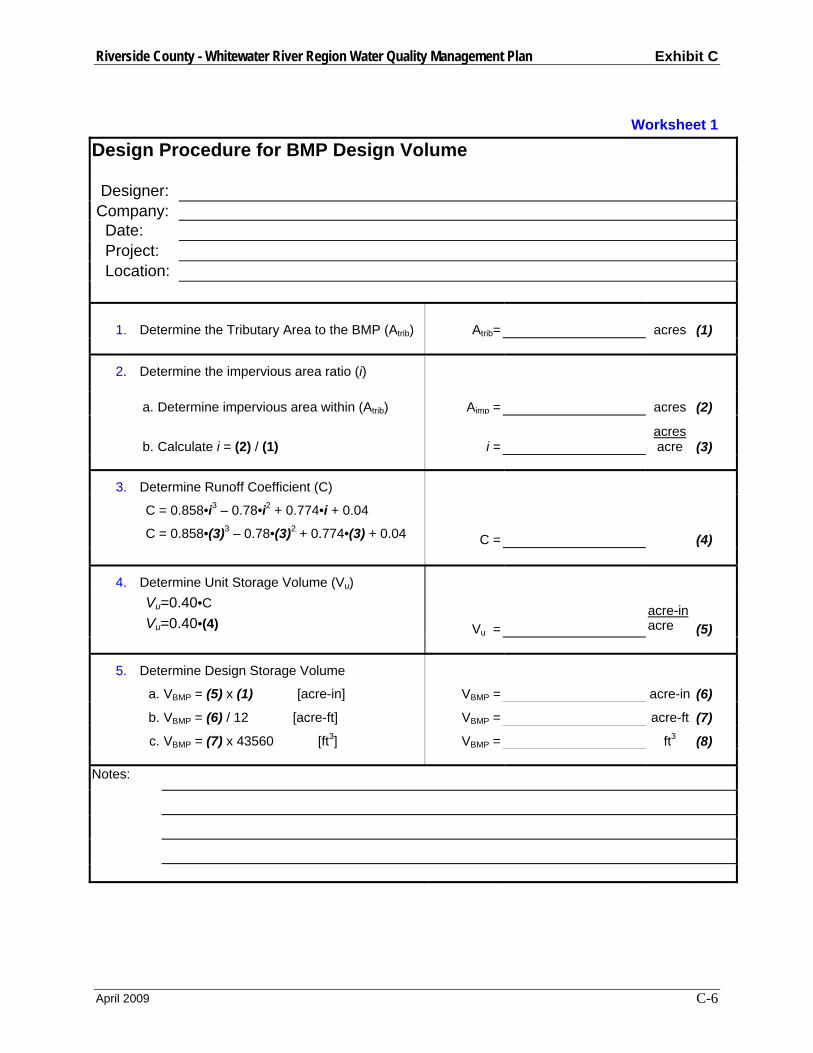
Riverside County - Whitewater River Region Water Quality Management Plan Exhibit C
April 2009 C-6
Worksheet 1
Design Procedure for BMP Design Volume Designer: Company: Date: Project: Location:
1. Determine the Tributary Area to the BMP (Atrib) Atrib= acres (1)
2. Determine the impervious area ratio (i)
a. Determine impervious area within (Atrib) Aimp = acres (2)
b. Calculate i = (2) / (1) i = acres
acre (3)
3. Determine Runoff Coefficient (C)
C = 0.858•i3 – 0.78•i2 + 0.774•i + 0.04
C = 0.858•(3)3 – 0.78•(3)2 + 0.774•(3) + 0.04 C = (4)
4. Determine Unit Storage Volume (Vu)
Vu=0.40•C Vu=0.40•(4) Vu =
acre-inacre (5)
5. Determine Design Storage Volume
a. VBMP = (5) x (1) [acre-in] VBMP = acre-in (6)
b. VBMP = (6) / 12 [acre-ft] VBMP = acre-ft (7)
c. VBMP = (7) x 43560 [ft3] VBMP = ft3 (8) Notes:

Riverside County - Whitewater River Region Water Quality Management Plan Exhibit C
April 2009 C-7
Flow Based BMPs General Flow based BMPs are sized to treat flows up to the design flow rate, which will remove pollutants to the MEP. This handbook bases the design flow rate on a uniform rainfall intensity of 0.2 inches per hour, as recommended by the California BMP Handbook. The flow rate is also dependent on the type of soil and percentage of impervious area in the development.
Uniform Intensity Approach The Uniform Intensity Approach is where the Design Rainfall Intensity, I is specified as:
I = 0.2 in/hr
That Intensity is then plugged into the Rational Equation to find the BMP design flow rate (Q).
QBMP = CIA
Where A = Tributary Area to the BMP C = Runoff Coefficient, based upon a Rainfall Intensity = 0.2 in/hr I = Design Rainfall intensity, 0.2 in/hr A step-by-step procedure for calculating the design flow rate is presented on Worksheet 2. Table 4 shows runoff coefficient values pertaining to the type of soils and percent imperviousness.
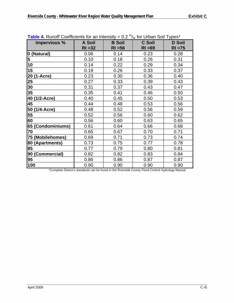
Riverside County - Whitewater River Region Water Quality Management Plan Exhibit C
April 2009 C-8
Table 4. Runoff Coefficients for an Intensity = 0.2 in/hr for Urban Soil Types*
Impervious % A Soil RI =32
B Soil RI =56
C Soil RI =69
D Soil RI =75
0 (Natural) 0.06 0.14 0.23 0.28 5 0.10 0.18 0.26 0.31 10 0.14 0.22 0.29 0.34 15 0.19 0.26 0.33 0.37 20 (1-Acre) 0.23 0.30 0.36 0.40 25 0.27 0.33 0.39 0.43 30 0.31 0.37 0.43 0.47 35 0.35 0.41 0.46 0.50 40 (1/2-Acre) 0.40 0.45 0.50 0.53 45 0.44 0.48 0.53 0.56 50 (1/4-Acre) 0.48 0.52 0.56 0.59 55 0.52 0.56 0.60 0.62 60 0.56 0.60 0.63 0.65 65 (Condominiums) 0.61 0.64 0.66 0.68 70 0.65 0.67 0.70 0.71 75 (Mobilehomes) 0.69 0.71 0.73 0.74 80 (Apartments) 0.73 0.75 0.77 0.78 85 0.77 0.79 0.80 0.81 90 (Commercial) 0.82 0.82 0.83 0.84 95 0.86 0.86 0.87 0.87 100 0.90 0.90 0.90 0.90
*Complete District’s standards can be found in the Riverside County Flood Control Hydrology Manual

Riverside County - Whitewater River Region Water Quality Management Plan Exhibit C
April 2009 C-9
Worksheet 2
Design Procedure Form for Design Flow Uniform Intensity Design Flow
Designer: Company: Date: Project: Location:
1. Determine Impervious Percentage
a. Determine total tributary area Atotal = acres (1) b. Determine Impervious % i = % (2)
2. Determine Runoff Coefficient Values Use Table 4 and impervious % found in step 1
a. A Soil Runoff Coefficient Ca = (3) b. B Soil Runoff Coefficient Cb = (4) c. C Soil Runoff Coefficient Cc = (5) d. D Soil Runoff Coefficient Cd = (6)
3. Determine the Area decimal fraction of each soil type in tributary area
a. Area of A Soil / (1) = Aa = (7) b. Area of B Soil / (1) = Ab = (8) c. Area of C Soil / (1) = Ac = (9) d. Area of D Soil / (1) = Ad = (10)
4. Determine Runoff Coefficient
a. C = (3)x(7) + (4)x(8) + (5)x(9) + (6)x(10) = C = (11)
5. Determine BMP Design flow
a. QBMP = C x I x A = (11) x 0.2 x (1) QBMP = ft3s (12)

Riverside County - Whitewater River Region Water Quality Management Plan Exhibit C
April 2009 C-10
Extended Detention Basins General An extended detention Basin is a permanent basin sized to detain and slowly release the design volume of stormwater, allowing particles and associated pollutants to settle out. An inlet forebay section and an inlet energy dissipater minimize erosion from entering flows, while erosion protection at the outlet prevents damage from exiting flows. The bottom of the basin slopes towards the outlet at an approximate grade of two percent, and a low flow channel conveys incidental flows directly to the outlet end of the basin. The basin should be vegetated earth in order to allow some infiltration to occur, although highly pervious soils may require an impermeable liner to prevent groundwater contamination. Proper turf management is also required to ensure that the vegetation does not contribute to water pollution through pesticides, herbicides, or fertilizers. A permanent micropool should not be included due to vector concerns. See Figure 3 for a typical basin design and Figure 5 for several outlet options. Extended detention basins can also be used to reduce the peaks of storm events for flood control purposes.
The basin outlet is designed to release the design runoff over a 48-hour drawdown period. The drawdown time refers to the minimum amount of time the design volume must be retained. In order to avoid vector breeding problems, the design volume should always empty within 72 hours. To function properly, the outlet must also be sized to retain the first half of the design volume for a minimum of 24 hours.
Extended Detention Basin Design Criteria:
Design Parameter Unit Design Criteria
Design Volume ft3 VBMP
Drawdown time (total) hrs 48 hrs 3 Drawdown time for 50% VBMP (minimum)
hrs 24 hrs 3
Minimum tributary area acre 5 acres 3 Inlet/outlet erosion control - Energy dissipater to reduce velocities 1 Forebay volume % 5 to 10 % of VBMP 1 Forebay drain time min Drain time < 45 minutes 1 Low-flow channel depth in 9 1 Low-flow chan. flow capacity - 2 times the forebay outlet rate 1 Bottom slope of upper stage % 2.0 1 Length to width ratio (min.) - 2:1 (larger preferred) 1 Upper stage depth/width (min.)
ft 2’ depth / 30’ width 1
Bottom stage volume % 10 to 25 % of VBMP 1 Bottom stage depth ft 1.5 to 3 ft deeper than top stage 1 Freeboard (minimum) ft 1.0 1 Embankment side slope - ≥ 3:1 inside / ≥ 4:1 outside (w/o retaining

Riverside County - Whitewater River Region Water Quality Management Plan Exhibit C
April 2009 C-11
(H:V) walls) 1 Maintenance access ramp slope
% 10 % or flatter 1
Maintenance access ramp width
ft 15’ – approach paved with asphalt concrete 1
1. Ventura County’s Technical Guidance Manual for Stormwater Quality Control Measures 2. City of Modesto’s Guidance Manual for New Development Stormwater Quality Control Measures 3. CA Stormwater BMP Handbook for New Development and Significant Redevelopment 4. Riverside County DAMP Supplement A Attachment
Extended Detention Basin Design Procedure 1. Design Volume
Use Worksheet 1- Design Procedure Form for Design Volume, VBMP. 1. Basin Shape
Whenever possible, shape the basin with a gradual expansion from the inlet toward the middle and a gradual contraction from middle toward the outlet. The length to width ratio should be a minimum of 2:1. Internal baffling with berms may be necessary to achieve this ratio.
2. Two-Stage Design Whenever feasible, provide a two-stage design with a pool that fills often with frequently occurring runoff. This minimizes standing water and sediment deposition in the remainder of the basin. a. Upper stage: The upper stage should be a minimum of 2 feet deep with the
bottom sloped at 2 percent toward the low flow channel. Minimum width of the upper stage should be 30 feet.
b. Bottom stage: The active storage basin of the bottom stage should be 1.5 to 3
feet deeper than the top stage and store 10 to 25 percent of the design volume. 3. Forebay Design
The forebay provides a location for sedimentation of larger particles that has a solid bottom surface to facilitate mechanical removal of accumulated sediment. The forebay volume should be 5 to 10 percent of the VBMP. A berm should separate the forebay from the upper stage of the basin. The outlet pipe from the forebay to the low-flow channel should be sized to drain the forebay volume in 45 minutes. The outlet pipe entrance should be offset from the forebay inlet to prevent short circuiting.
4. Low-flow Channel
The low flow channel conveys flow from the forebay to the bottom stage. Erosion protection should be provided where the low-flow channel enters the bottom stage. Lining of the low flow channel with concrete is recommended. The depth of the
Riverside County - Whitewater River Region Water Quality Management Plan Exhibit C
April 2009 C-12
channel should be at least 9 inches. The flow capacity of the channel should be twice the release capacity of the forebay outlet.
5. Trash Rack/Gravel Pack A trash rack or gravel pack around perforated risers shall be provided to protect outlet orifices from clogging. Trash racks are better suited for use with perforated vertical plates for outlet control and allow easier access to outlet orifices for purposes of inspection and cleaning. Trash rack shall be sized to prevent clogging of the primary water quality outlet without restricting the hydraulic capacity of the outlet control orifices.
6. Basin Outlet The basin outlet should be sized to release the design volume, VBMP over a 48-hour period, with no more than 50 percent released in 24 hours. The outflow structure should have a trash rack or other acceptable means to prevent clogging, and a valve that can stop discharge from being released in case of an accidental spill in the watershed (Figure 5). The discharge through a control orifice can be calculated using the following steps: a. Develop a Stage vs. Discharge curve for the outlet structure b. For example: If using an orifice, select the orifice size and use the following
equation to develop a Stage vs. Discharge relationship for this outlet: Q = CA[2g(H-Ho)]0.5 Where: Q = discharge (ft3/s)
C = orifice coefficient A = area of the orifice (ft) G = gravitational constant (32.2 ft2/s) H = water surface elevation (ft) Ho = orifice elevation (ft)
Recommended values for C are 0.66 for thin material (e.g. CMP riser) and 0.8 when the material is thicker than the orifice diameter (e.g. concrete riser). Alternative non-mechanical hydraulic control structures are acceptable (e.g. weirs, risers, etc).
c. Develop a Stage vs. Volume curve for the basin
Based on the shape and size of the basin, develop a relationship between the stage and the volume of water in the basin.
d. Create an Inflow Hydrograph
Create an inflow hydrograph that delivers the design volume VBMP instantaneously to the basin. This can be approximated by creating a hydrograph with two 5-minute intervals that together convey the entire VBMP.
e. Route the Volume through the Basin
Riverside County - Whitewater River Region Water Quality Management Plan Exhibit C
April 2009 C-13
Route the volume of water through the basin using these curves. If this meets the hydraulic retention time requirements (50% of the volume empties in not less than 24 hours, 100% of the volume empties in not less than 48 hours and not more than 72 hours) the outlet is correctly sized. If these requirements are not met, select a new outlet size or configuration and repeat the process.
7. Inlet/Outlet Design Basin inlet and outlet points should be provided with an energy dissipation structure and/or erosion protection.
8. Turf Management Basin vegetation provides erosion protection and improves sediment entrapment. Basin bottoms, berms, and side slopes may be planted with native grasses or with irrigated turf. Several BMPs must be implemented to ensure that this vegetation does not contribute to water pollution through pesticides, herbicides, or fertilizers. These BMPs shall include, at a minimum: (1) educational activities, permits, certifications, and other measures for local applicators and distributors; (2) integrated pest management measures that rely on non-chemical solutions; (3) the use of native vegetation; (4) schedules for irrigation and chemical application; and (5) the collection and proper disposal of unused pesticides, herbicides, and fertilizers.
9. Embankment
Embankment designs must conform to requirements of the State of California Division of Safety of Dams, if the basin dimensions cause it to fall under that agency’s jurisdiction. Interior slopes should be no steeper than 2:1 and exterior slopes no steeper than 4:1. Flatter slopes are preferable. Embankment fill is discouraged and should never be higher than three feet unless the basin is to be publicly maintained.
10. Access
All-weather access to the bottom, forebay, and outlet works shall be provided for maintenance vehicles. Maximum grades of access ramps should be 10 percent and minimum width should be 15 feet.
11. Bypass
Provide for bypass or overflow of runoff volumes in excess of the design volume. Spillway and overflow structures should be designed in accordance with applicable standards of the Riverside County Flood Control District.
12. Geotextile Fabric
Non-woven geotextile fabric used in conjunction with gravel packs around perforated risers shall conform with the specifications located in Table 5.
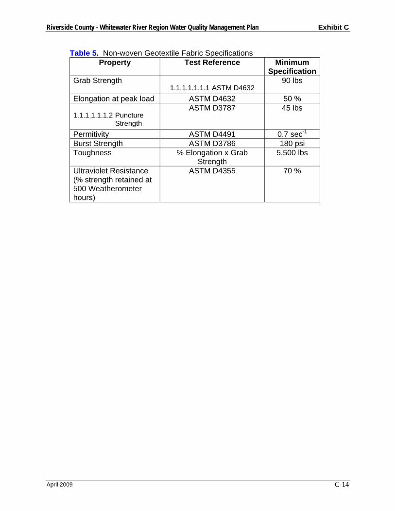
Riverside County - Whitewater River Region Water Quality Management Plan Exhibit C
April 2009 C-14
Table 5. Non-woven Geotextile Fabric Specifications Property Test Reference Minimum
Specification Grab Strength
1.1.1.1.1.1.1 ASTM D4632 90 lbs
Elongation at peak load ASTM D4632 50 %
1.1.1.1.1.1.2 Puncture Strength
ASTM D3787 45 lbs
Permitivity ASTM D4491 0.7 sec-1 Burst Strength ASTM D3786 180 psi Toughness % Elongation x Grab
Strength 5,500 lbs
Ultraviolet Resistance (% strength retained at 500 Weatherometer hours)
ASTM D4355 70 %
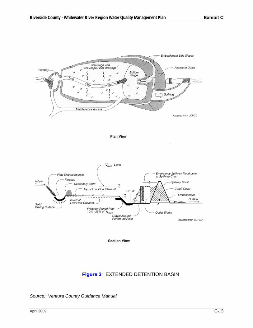
Riverside County - Whitewater River Region Water Quality Management Plan Exhibit C
April 2009 C-15
Figure 3: EXTENDED DETENTION BASIN
Source: Ventura County Guidance Manual

Riverside County - Whitewater River Region Water Quality Management Plan Exhibit C
April 2009 C-16
Figure 4: EXTENDED DETENTION / INCREASED RUNOFF BASIN
Source: CA BMP Handbook (2003)
Riverside County - Whitewater River Region Water Quality Management Plan Exhibit C
April 2009 C-17
Figure 5: EXTENDED DETENTION BASIN TYPICAL OUTLETS
Source: Ventura County Guidance Manual
Riverside County - Whitewater River Region Water Quality Management Plan Exhibit C
April 2009 C-18
Worksheet 3 Design Procedure Form for Extended Detention Basin Designer:__________________________________________________________ Company:_________________________________________________________ Date:_____________________________________________________________ Project:___________________________________________________________ Location:__________________________________________________________ 1. Determine Design Volume (Use
Worksheet 1) a. Total Tributary Area (minimum 5
ac.) b. Design Volume, VBMP
Atotal = __________ acres VBMP = __________ ft3
2. Basin Length to Width Ratio (2:1 min.)
Ratio = __________ L:W
3. Two-Stage Design
a. Overall Design 1) Depth (3.5’ min.) 2) Width (30’ min.) 3) Length (60’ min.) 4) Volume (must be ≥ VBMP)
b. Upper Stage 1) Depth (2’ min.) 2) Bottom Slope (2% to low flow
channel recommended) c. Bottom Stage
1) Depth (1.5’ to 3’) 2) Length 3) Volume (10 to 25% of VBMP)
Depth = __________ ft Width = __________ ft Length = __________ ft Volume = __________ ft3 Depth = __________ ft Slope = __________ % Depth = __________ ft Length = __________ ft Volume = __________ ft3
4. Forebay Design
a. Forebay Volume (5 to 10% of VBMP) b. Outlet pipe drainage time (≅ 45
min)
Volume = __________ ft3 Drain time = __________ minutes
5. Low-flow Channel
a. Depth (9” minimum) b. Flow Capacity (2 * Forebay QOUT)
Depth = _________ ft QLow Flow = _________ cfs
6. Trash Rack or Gravel Pack (check one)
Trash Rack ______ Gravel Pack ______
Riverside County - Whitewater River Region Water Quality Management Plan Exhibit C
April 2009 C-19
7. Basin Outlet
a. Outlet type (check one)
b. Orifice Area c. Orifice Type d. Maximum Depth of water above
bottom orifice e. Length of time for 50% VBMP
drainage (24 hour minimum) f. Length of time for 100% VBMP
drainage (between 48 and 72 hours)
g. Attached Documents (all required) 1) Stage vs. Discharge 2) Stage vs. Volume 3) Inflow Hydrograph 4) Basin Routing
Single orifice _____ Multi-orifice plate _____ Perforated Pipe _____ Other ___________________ Area = __________ ft2 Type ______________________ Depth = __________ ft Time 50% = __________ hrs Time 100% = __________ hrs Attached Documents (check) 1) __________
2) __________ 3) __________ 4) __________
8. Increased Runoff (optional)
Is this basin also mitigating increased runoff? Attached Documents (all required) for 2, 5, & 10-year storms:
1) Stage vs. Discharge 2) Stage vs. Volume 3) Inflow Hydrograph 4) Basin Routing
Yes ______ No ______ (if No, skip to #9) Attached Documents (check) 1) __________
2) __________ 3) __________ 4) __________
9. Vegetation (check type)
____ Native Grasses ____ Irrigated Turf ____ Other ___________________________
10. Embankment
a. Interior slope (4:1 max.) b. Exterior slope (3:1 max.)
Interior Slope = _________ % Exterior Slope = _________ %
11. Access
a. Slope (10% max.) b. Width (16 feet min.)
Slope = __________ % Width = __________ ft

Riverside County - Whitewater River Region Water Quality Management Plan Exhibit C
April 2009 C-20
Notes:
Riverside County - Whitewater River Region Water Quality Management Plan Exhibit C
April 2009 C-21
Infiltration Basins General An infiltration basin is an earthen basin designed to capture the design volume of runoff and infiltrate that stormwater back into the pervious natural surrounding soil. These basins have only an emergency spillway, not a standard outlet, although a relief underdrain will drain the basin if standing water conditions occur. Flows that exceed the design volume should be diverted around the infiltration basin. The basin is designed to retain the design volume and allow it to percolate into the underlying soil over a period of 48 hours, which removes soluble and fine particulate pollutants. Sediment clogging can be avoided by including a settling basin near the inlet as well as the required energy dissipater. The sides and bottom of the basin include vegetation to protect the basin from erosion. Infiltration basins typically treat developments up to 50 acres in size.
Infiltration basins have select applications. Their use is often sharply restricted by concerns over ground water contamination, soils, and clogging at the site. These basins are not appropriate for the following site conditions: industrial sites or locations where spills occur, sites with C or D type soils, and sites with high infiltration rates where pollutants can affect ground water quality. The upstream tributary area must be completely stabilized before construction. In addition, some studies have shown relatively high failure rates compared with other management practices. Finally, infiltration basins are difficult to restore infiltration once the basin has been clogged.
Infiltration Basin Design Criteria:
Design Parameter Unit Design Criteria Design Volume ft3 VBMP Drawdown time hrs 48 hrs 3 Maximum Tributary Area acre 50 acres 4 Minimum Infiltration Rate in/hr 0.5 in/hr 4 Bottom Basin elevation ft 5 feet or more above seasonally high
groundwater table 1 Minimum Freeboard ft 1.0 ft 1 Setbacks ft
100 feet from wells, tanks, fields, springs 1 20 feet down slope of 100 feet up slope from foundations 1
Inlet/outlet erosion control - Energy dissipater to reduce inlet/outlet velocity 1
Embankment side slope (H:V)
-
4:1 or flatter inside slope/ 3:1 or flatter outside slope (without retaining walls) 1
Maintenance access ramp slope (H:V)
- 10:1 or flatter 1
Maintenance access ramp width
ft 16.0 – approach paved with asphalt concrete1
Vegetation - Side slopes and bottom (may require
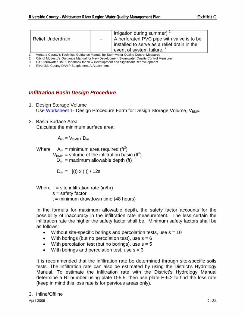
Riverside County - Whitewater River Region Water Quality Management Plan Exhibit C
April 2009 C-22
irrigation during summer) 1 Relief Underdrain - A perforated PVC pipe with valve is to be
installed to serve as a relief drain in the event of system failure. 2
1 Ventura County’s Technical Guidance Manual for Stormwater Quality Control Measures 2 City of Modesto’s Guidance Manual for New Development Stormwater Quality Control Measures 3 CA Stormwater BMP Handbook for New Development and Significant Redevelopment 4 Riverside County DAMP Supplement A Attachment
Infiltration Basin Design Procedure 1. Design Storage Volume
Use Worksheet 1- Design Procedure Form for Design Storage Volume, VBMP.
2. Basin Surface Area Calculate the minimum surface area: Am = VBMP / Dm Where Am = minimum area required (ft2)
VBMP = volume of the infiltration basin (ft3) Dm = maximum allowable depth (ft)
Dm = [(t) x (I)] / 12s
Where I = site infiltration rate (in/hr) s = safety factor t = minimum drawdown time (48 hours)
In the formula for maximum allowable depth, the safety factor accounts for the possibility of inaccuracy in the infiltration rate measurement. The less certain the infiltration rate the higher the safety factor shall be. Minimum safety factors shall be as follows:
• Without site-specific borings and percolation tests, use s = 10 • With borings (but no percolation test), use s = 6 • With percolation test (but no borings), use s = 5 • With borings and percolation test, use s = 3
It is recommended that the infiltration rate be determined through site-specific soils tests. The Infiltration rate can also be estimated by using the District’s Hydrology Manual. To estimate the infiltration rate with the District’s Hydrology Manual determine a RI number using plate D-5.5, then use plate E-6.2 to find the loss rate (keep in mind this loss rate is for pervious areas only).
3. Inline/Offline

Riverside County - Whitewater River Region Water Quality Management Plan Exhibit C
April 2009 C-23
Basins may be on-line or off-line with flood control facilities. For on-line basins, the water quality outlet may be superimposed on the flood control outlet or may be constructed as a separate outlet.
4. Basin Inlet
The inlet structure should dissipate energy of incoming flow to avoid scouring of the basin. If high sediment loads are anticipated a settling basin with a volume of 10 to 20 percent of the design volume should be placed at the inlet of the basin.
5. Vegetation
Bottom vegetation provides erosion protection and sediment entrapment. Basin bottoms, berms, and side slopes may be planted with native grasses or with irrigated turf.
6. Embankments Design embankments to conform to requirements of State of California Division of Safety of Dams, if the basin dimensions cause it to fall under that agency’s jurisdiction. Interior slopes should be no steeper than 4:1 and exterior slopes no steeper than 3:1. Flatter slopes are preferable.
7. Access
All-weather access to the bottom, forebay, and outlet works shall be provided for maintenance vehicles. Maximum grades of access ramps should be 10 percent and minimum width should be 16 feet. Ramps should be paved with concrete. Provide security fencing, except when used as a recreation area.
8. Bypass
Provide for bypass or overflow of runoff volumes in excess of the design volume. Spillway and overflow structures should be designed in accordance with applicable standards of the Riverside County Flood Control District.

Riverside County - Whitewater River Region Water Quality Management Plan Exhibit C
April 2009 C-24
Figure 6: INFILTRATION BASIN
Source: City of Modesto Guidance Manual
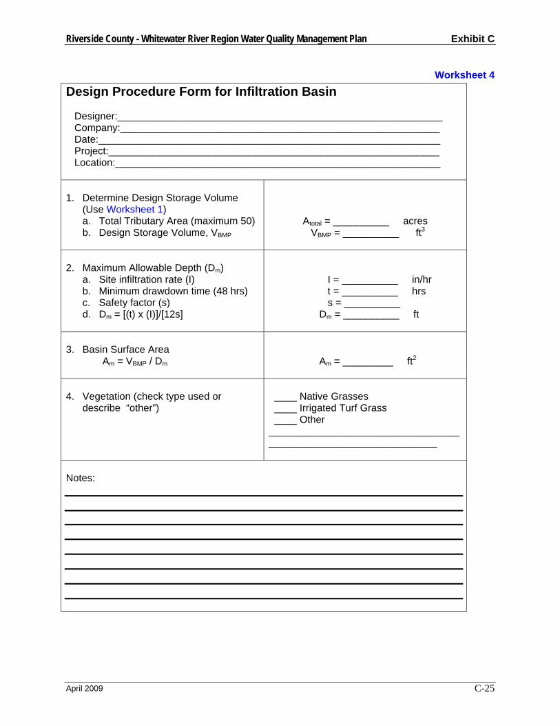
Riverside County - Whitewater River Region Water Quality Management Plan Exhibit C
April 2009 C-25
Worksheet 4 Design Procedure Form for Infiltration Basin Designer:__________________________________________________________ Company:_________________________________________________________ Date:_____________________________________________________________ Project:___________________________________________________________ Location:__________________________________________________________ 1. Determine Design Storage Volume
(Use Worksheet 1) a. Total Tributary Area (maximum 50) b. Design Storage Volume, VBMP
Atotal = __________ acres VBMP = __________ ft3
2. Maximum Allowable Depth (Dm)
a. Site infiltration rate (I) b. Minimum drawdown time (48 hrs) c. Safety factor (s) d. Dm = [(t) x (I)]/[12s]
I = __________ in/hr t = __________ hrs s = __________ Dm = __________ ft
3. Basin Surface Area Am = VBMP / Dm
Am = _________ ft2
4. Vegetation (check type used or
describe “other”)
____ Native Grasses ____ Irrigated Turf Grass ____ Other ________________________________________________________________
Notes:
Riverside County - Whitewater River Region Water Quality Management Plan Exhibit C
April 2009 C-26
Infiltration Trenches General An infiltration trench is an excavated trench that has been refilled with a gravel and sand bed capable of holding the design volume of stormwater runoff. The runoff is stored in the trench over a period of time (48 hours) during which it slowly infiltrates back into the naturally pervious surrounding soil. This infiltration process effectively removes soluble and particulate pollutants, however it is not intended to trap course sediments. It is recommended that an upstream control measure such as a grass swale or filter strip be combined with an infiltration trench to remove sediments that might clog the trench. These trenches also include a bypass system for volumes greater than the design capture volume, and a perforated pipe as an observation well to monitor water depth. An infiltration trench can typically treat developments up to 10 acres.
Infiltration Trench Design Criteria
Design Parameter Unit Design Criteria
Design Volume ft3 VBMP
Drawdown time hrs 48 hrs 3
Maximum Tributary Area acre 10 acres 2 & 3
Minimum Infiltration Rate of Soil
in/hr 0.27 in/hr 4
Trench bottom elevation ft 5 feet or more above seasonally high groundwater table 1
Maximum Trench depth (Dm) ft 8.0 ft 1
Gravel bed material ft Clean, washed aggregate 1 to 3 inches in diameter 1
Trench lining material - Geotextile fabric 1 or 6” layer of sand 4
Setbacks ft
100 feet from wells, tanks, fields, or springs 1
20 feet down slope or 100 feet up slope from foundations 1
Do not locate under tree drip-lines 1 1 Ventura County’s Technical Guidance Manual for Stormwater Quality Control Measures 2 City of Modesto’s Guidance Manual for New Development Stormwater Quality Control Measures 3 CA Stormwater BMP Handbook for New Development and Significant Redevelopment 4 Riverside County DAMP Supplement A Attachment
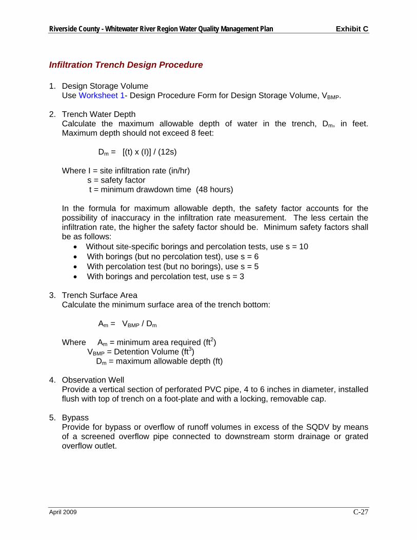
Riverside County - Whitewater River Region Water Quality Management Plan Exhibit C
April 2009 C-27
Infiltration Trench Design Procedure 1. Design Storage Volume
Use Worksheet 1- Design Procedure Form for Design Storage Volume, VBMP.
2. Trench Water Depth Calculate the maximum allowable depth of water in the trench, Dm, in feet. Maximum depth should not exceed 8 feet: Dm = [(t) x (I)] / (12s) Where I = site infiltration rate (in/hr) s = safety factor t = minimum drawdown time (48 hours) In the formula for maximum allowable depth, the safety factor accounts for the possibility of inaccuracy in the infiltration rate measurement. The less certain the infiltration rate, the higher the safety factor should be. Minimum safety factors shall be as follows:
• Without site-specific borings and percolation tests, use s = 10 • With borings (but no percolation test), use s = 6 • With percolation test (but no borings), use s = 5 • With borings and percolation test, use s = 3
3. Trench Surface Area
Calculate the minimum surface area of the trench bottom: Am = VBMP / Dm Where Am = minimum area required (ft2)
VBMP = Detention Volume (ft3) Dm = maximum allowable depth (ft)
4. Observation Well
Provide a vertical section of perforated PVC pipe, 4 to 6 inches in diameter, installed flush with top of trench on a foot-plate and with a locking, removable cap.
5. Bypass
Provide for bypass or overflow of runoff volumes in excess of the SQDV by means of a screened overflow pipe connected to downstream storm drainage or grated overflow outlet.

Riverside County - Whitewater River Region Water Quality Management Plan Exhibit C
April 2009 C-28
Figure 7: INFILTRATION TRENCH
Source: Ventura County Guidance Manual

Riverside County - Whitewater River Region Water Quality Management Plan Exhibit C
April 2009 C-29
Worksheet 5 Design Procedure Form for Infiltration Trench Designer:__________________________________________________________ Company:_________________________________________________________ Date:_____________________________________________________________ Project:___________________________________________________________ Location:__________________________________________________________ 1. Determine Design Storage Volume
(Use worksheet 1) a. Total Tributary Area (maximum 10) b. Design Storage Volume, VBMP
Atotal = __________ acres VBMP = __________ ft3
2. Maximum Allowable Depth (Dm =
tl/12s) a. Site infiltration rate (I) b. Minimum drawdown time (t = 48
hrs) c. Safety factor (s) d. Dm = tl/12s
I = __________ in/hr t = __________ hrs s = __________ Dm = __________ ft
3. Trench Bottom Surface Area Am = VBMP / Dm
Am = _________ ft2
Notes:

Riverside County - Whitewater River Region Water Quality Management Plan Exhibit C
April 2009 C-30
Porous Pavement General Porous Pavement is an infiltration BMP that consists of porous pavement blocks placed over a shallow recharge bed of sand and gravel. It is typically restricted to low volume parking areas that do not receive significant offsite runoff. The modular pavement blocks allow water to seep into the recharge bed, where the sand and gravel layers percolate the design volume into the natural surrounding soils. Porous Pavement can be used for areas of up to 10 acres.
Porous Pavement Design Criteria:
Design Parameter Unit Design Criteria
Design Volume ft3 VBMP Drawdown Time hrs 12 hours 1 Maximum Tributary Area acre 10 acres 2,4 Maximum contributing area slope
% 5 % 2,4
Traffic Use - Locate in areas of low intensity traffic use 2,4
Erosion - Avoid areas of high wind erosion 2 Placement - Do not locate in narrow strips between
areas of impervious pavement 2 Land use - Do not use in high-risk land uses, i.e.
service/gas stations, truck stops, heavy industrial sites 2
Sediment - Sediment-laden runoff must be directed away from the porous pavement/recharge bed. Place filter fabric on the floor and sides of the recharge bed. 2
Modular Porous Block Type
% 40% surface area open 1
Porous Pavement Infill - ASTM C-33 Sand or equivalent 1 Base Course inches 1” sand (ASTM C-33) over 9” gravel 1 Perimeter Wall Width inches 6 inches 1
1 Ventura County’s Technical Guidance Manual for Stormwater Quality Control Measures 2 City of Modesto’s Guidance Manual for New Development Stormwater Quality Control Measures 3 CA Stormwater BMP Handbook for New Development and Significant Redevelopment 4 Riverside County DAMP Supplement A Attachment
Riverside County - Whitewater River Region Water Quality Management Plan Exhibit C
April 2009 C-31
Porous Pavement Design Procedure 1. Design Storage Volume
Use Worksheet 1- Design Procedure Form for Design Storage Volume, VBMP.
2. Basin Surface Area
Calculate minimum required surface area, Am, based on surcharge depth of 2
inches as follows: Am = VBMP / 0.17 ft 3. Select Block Type
Select appropriate modular blocks that have no less than 40 percent of the surface area open. The manufacturer’s installation requirements shall be followed with the exception of the infill material and base dimensions, which will meet the criteria listed in this manual.
4. Porous Pavement Infill
The pavement block openings should be filled with ASTM C-33 graded sand (fine concrete aggregate, not sandy loam turf).
5. Base Courses
Provide a 1-inch thick sand base course over a 9-inch thick gravel base course. 6. Perimeter Wall
Provide a concrete perimeter wall to confine the edges of the pavement area. The wall should be minimum 6-inch wide and at least 6 inches deeper than all the porous media and modular block depth combined.
7. Sub-base
If expansive soils or rock are a concern or the tributary catchment has chemical or petroleum products handled or stored, install an impermeable membrane below the base course. Otherwise install a non-woven geotextile membrane to encourage filtration.
8. Overflow
Provide an overflow, possibly with an inlet to a storm sewer, set at 2 inches above the level of the porous pavement surface. Make sure the 2-inch ponding depth is contained and does not flow out of the area at ends or sides.

Riverside County - Whitewater River Region Water Quality Management Plan Exhibit C
April 2009 C-32
Figure 8: Porous Pavement Detention
Source: Ventura County Guidance Manual
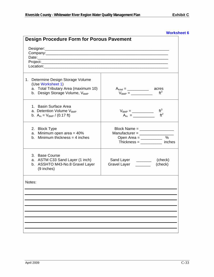
Riverside County - Whitewater River Region Water Quality Management Plan Exhibit C
April 2009 C-33
Worksheet 6 Design Procedure Form for Porous Pavement Designer:__________________________________________________________ Company:_________________________________________________________ Date:_____________________________________________________________ Project:___________________________________________________________ Location:__________________________________________________________ 1. Determine Design Storage Volume
(Use Worksheet 1) a. Total Tributary Area (maximum 10) b. Design Storage Volume, VBMP
Atotal = __________ acres VBMP = __________ ft3
1. Basin Surface Area a. Detention Volume VBMP b. Am = VBMP / (0.17 ft)
VBMP = __________ ft3 Am = __________ ft2
2. Block Type a. Minimum open area = 40% b. Minimum thickness = 4 inches
Block Name = ________________ Manufacturer = ________________ Open Area = __________ % Thickness = __________ inches
3. Base Course a. ASTM C33 Sand Layer (1 inch) b. ASSHTO M43-No.8 Gravel Layer
(9 inches)
Sand Layer _______ (check) Gravel Layer _______ (check)
Notes:
Riverside County - Whitewater River Region Water Quality Management Plan Exhibit C
April 2009 C-34
Sand Filters General
Sand Filters capture and treat the design runoff in a two-part system, first a settling basin, then a filter bed. The settling basin collects large sediment and prevents these particles from clogging the filter bed. The sand bed then strains the water, removing soluble and particulate pollutants. The treated water is conveyed through pipes back into a stream or channel. Sand Filters are especially useful where water quality concerns might preclude the use of infiltration BMPs.
There are many variations of sand filter designs, and it is up to the designer to determine the most effective sand filter to use in each case. Two of the most common sand filters, the Austin sand filter and the Delaware sand filter, have been conditioned in this manual. Although the Austin filter was not included in the Attachment, it was added to this manual because it can treat a very large tributary area and because it is well suited to southern California. Other sand filter designs may be used if it is shown that they are more appropriate.
Some of the limitations associated with Sand Filters include: higher requirement for hydraulic head (typically > 4’), they work best for small tributary areas, vector problems with permanent standing water for certain Sand Filters, and the addition of concrete walls may cause aesthetic and safety problems.
Austin Sand Filter
The Austin Sand Filter, as developed by the city of Austin, Texas, is an aboveground sand filter that does not include a permanent wet pool. The filter inlet captures the design volume, while directing larger flows past. The first chamber of the filter is the sedimentation basin, which holds the entire design volume (this handbook conditions a full sedimentation design). The design volume drains into the second chamber, which is the filtration basin, over a period of 48 hours. This allows large particles to settle in the sedimentation basin and protects the filter bed from clogging. The sand and gravel filter bed removes soluble and particulate pollutants, and the treated water is returned to a storm drain. In order to drain by gravity, an Austin sand filter must be located in an area where the topography has sufficient vertical drops. These filters can be used to treat runoff from areas up to 100 acres large.
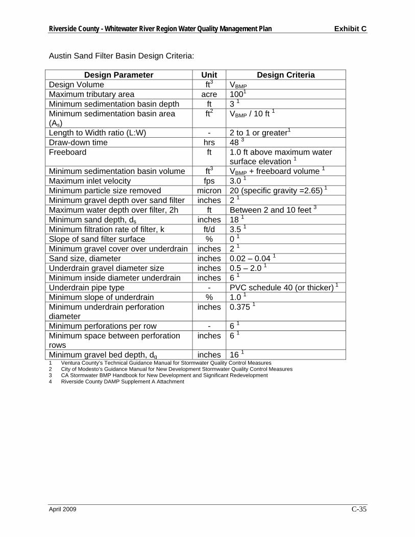
Riverside County - Whitewater River Region Water Quality Management Plan Exhibit C
April 2009 C-35
Austin Sand Filter Basin Design Criteria:
Design Parameter Unit Design Criteria Design Volume ft3 VBMP Maximum tributary area acre 1001 Minimum sedimentation basin depth ft 3 1 Minimum sedimentation basin area (As)
ft2 VBMP / 10 ft 1
Length to Width ratio (L:W) - 2 to 1 or greater1 Draw-down time hrs 48 3 Freeboard ft 1.0 ft above maximum water
surface elevation 1 Minimum sedimentation basin volume ft3 VBMP + freeboard volume 1 Maximum inlet velocity fps 3.0 1 Minimum particle size removed micron 20 (specific gravity =2.65) 1 Minimum gravel depth over sand filter inches 2 1 Maximum water depth over filter, 2h ft Between 2 and 10 feet 3 Minimum sand depth, ds inches 18 1 Minimum filtration rate of filter, k ft/d 3.5 1 Slope of sand filter surface % 0 1 Minimum gravel cover over underdrain inches 2 1 Sand size, diameter inches 0.02 – 0.04 1 Underdrain gravel diameter size inches 0.5 – 2.0 1 Minimum inside diameter underdrain inches 6 1 Underdrain pipe type - PVC schedule 40 (or thicker) 1 Minimum slope of underdrain % 1.0 1 Minimum underdrain perforation diameter
inches 0.375 1
Minimum perforations per row - 6 1 Minimum space between perforation rows
inches 6 1
Minimum gravel bed depth, dg inches 16 1 1 Ventura County’s Technical Guidance Manual for Stormwater Quality Control Measures 2 City of Modesto’s Guidance Manual for New Development Stormwater Quality Control Measures 3 CA Stormwater BMP Handbook for New Development and Significant Redevelopment 4 Riverside County DAMP Supplement A Attachment
Riverside County - Whitewater River Region Water Quality Management Plan Exhibit C
April 2009 C-36
Austin Sand Filter Design Procedure
Part I – Sedimentation Basin Design 1. Design Storage Volume
Use Worksheet 1- Design Procedure Form for Design Storage Volume, VBMP.
2. Maximum Water Depth Determine maximum allowable depth of water (2h) in the sedimentation basin considering elevation differences between inlet and outlet inverts of the sedimentation basin and filter surface. (This sets the height or elevation of the inlet invert for bypass pipes and orifices).
3. Sedimentation Basin Design
The sedimentation basin design should maximize the distance from the inlet to the outlet while avoiding short circuiting (flow reaching the outlet structure before it passes through the sedimentation basin volume) and dead storage areas (areas in the basin that are bypassed by the main flow). The basin shape should include a gradual expansion from the inlet and a gradual contraction toward the outlet. The length to width ratio should be a minimum of 2:1. Internal baffling with berms may be necessary to achieve this ratio. a. Find the sedimentation basin area, As
As = VBMP / (2h) b. Determine the basin length and width
As = 2 x W2 length = 2 x width
4. Energy Dissipation Structure
Basin inlet and outlet points should include an energy dissipation structure and/or erosion protection. An energy dissipation structure is required when inlet velocities exceed 3 feet per second.
5. Sedimentation Inlet The inlet structure design must isolate the water quality volume and convey flows greater than the VBMP past the basin. The water quality volume should be discharged uniformly and at low velocities into the sedimentation basin.
6. Sedimentation Outlet
The outlet structure conveys the water quality volume from the sedimentation basin to the filtration basin. The outlet structure shall be designed to outlet the design volume (ponded to a height of 2h) into the filter basin over a drawdown period of 48 hours.
7. Trash Rack/Gravel Pack A trash rack or gravel pack around perforated risers shall be provided to protect outlet orifices from clogging.

Riverside County - Whitewater River Region Water Quality Management Plan Exhibit C
April 2009 C-37
8. Sediment Trap (optional)
Placing a sediment trap in the basin can improve long-term removal efficiency and reduce maintenance requirements.
Part II – Filter Basin Design 9. Filter Basin Surface Area
The required filter basin surface area (Af) can be calculated using the following simplified equation from the CA BMP Handbook: Af = VBMP / 18
10. Filter Basin Volume The storage capacity of the filtration basin, above the surface of the filter media, should be greater than or equal to 20 percent of the VBMP. This capacity is necessary in order to account for backwater effects resulting from partially clogged filter media. If the filter basin volume is less than the required volume, redesign with an increased filter depth or increase the filter area.
11. Filter Basin Inlet Structure
The inlet structure should spread the flow uniformly across the surface of the media filter. Flow spreaders, weirs or multiple orifice openings are recommended.
12. Filter Bed
The sand bed may be a choice of one of the two configurations given below. Note: Sand bed depths are final, consolidated depths. Consolidated effects must be taken into account. 1) Sand Bed with Gravel Layer (Figure 9A)
The sand layer is a minimum depth of 18 inches consisting of 0.02-0.04 inch diameter sand. Under the sand is a layer of 0.5 to 2.0 inch diameter gravel which provides a minimum of two inches of cover over the top of the underdrain lateral pipes. No gravel is required under the lateral pipes. A layer of geotextile fabric meeting the following specifications must separate the sand and gravel and must be wrapped around the lateral pipes:
Table 6. Geotextile Fabric Specifications
Property Test Method Unit Specification Material Nonwoven
geotextile fabric Unit Weight Oz/yd2 8 (minimum) Filtration Rate In/sec 0.08 (minimum)
Puncture Strength ASTM D-751 (modified)
Lb. 125 (minimum)
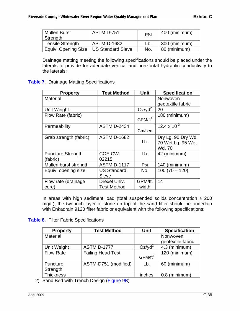
Riverside County - Whitewater River Region Water Quality Management Plan Exhibit C
April 2009 C-38
Mullen Burst Strength
ASTM D-751 PSI 400 (minimum)
Tensile Strength ASTM-D-1682 Lb. 300 (minimum) Equiv. Opening Size US Standard Sieve No. 80 (minimum)
Drainage matting meeting the following specifications should be placed under the laterals to provide for adequate vertical and horizontal hydraulic conductivity to the laterals:
Table 7. Drainage Matting Specifications
Property Test Method Unit Specification Material Nonwoven
geotextile fabric Unit Weight Oz/yd2 20 Flow Rate (fabric)
GPM/ft2 180 (minimum)
Permeability ASTM D-2434 Cm/sec
12.4 x 10⁻²
Grab strength (fabric) ASTM D-1682 Lb.
Dry Lg. 90 Dry Wd. 70 Wet Lg. 95 Wet Wd. 70
Puncture Strength (fabric)
COE CW-02215
Lb. 42 (minimum)
Mullen burst strength ASTM D-1117 Psi 140 (minimum) Equiv. opening size US Standard
Sieve No. 100 (70 – 120)
Flow rate (drainage core)
Drexel Univ. Test Method
GPM/ft. width
14
In areas with high sediment load (total suspended solids concentration ≥ 200 mg/L), the two-inch layer of stone on top of the sand filter should be underlain with Enkadrain 9120 filter fabric or equivalent with the following specifications:
Table 8. Filter Fabric Specifications
Property Test Method Unit Specification Material Nonwoven
geotextile fabric Unit Weight ASTM D-1777 Oz/yd2 4.3 (minimum) Flow Rate Failing Head Test
GPM/ft2 120 (minimum)
Puncture Strength
ASTM-D751 (modified) Lb. 60 (minimum)
Thickness inches 0.8 (minimum) 2) Sand Bed with Trench Design (Figure 9B)
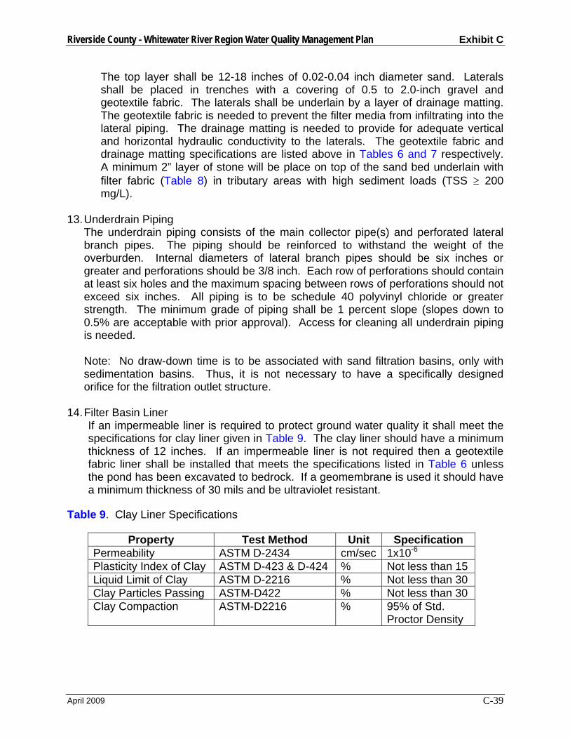
Riverside County - Whitewater River Region Water Quality Management Plan Exhibit C
April 2009 C-39
The top layer shall be 12-18 inches of 0.02-0.04 inch diameter sand. Laterals shall be placed in trenches with a covering of 0.5 to 2.0-inch gravel and geotextile fabric. The laterals shall be underlain by a layer of drainage matting. The geotextile fabric is needed to prevent the filter media from infiltrating into the lateral piping. The drainage matting is needed to provide for adequate vertical and horizontal hydraulic conductivity to the laterals. The geotextile fabric and drainage matting specifications are listed above in Tables 6 and 7 respectively. A minimum 2” layer of stone will be place on top of the sand bed underlain with filter fabric (Table 8) in tributary areas with high sediment loads (TSS ≥ 200 mg/L).
13. Underdrain Piping
The underdrain piping consists of the main collector pipe(s) and perforated lateral branch pipes. The piping should be reinforced to withstand the weight of the overburden. Internal diameters of lateral branch pipes should be six inches or greater and perforations should be 3/8 inch. Each row of perforations should contain at least six holes and the maximum spacing between rows of perforations should not exceed six inches. All piping is to be schedule 40 polyvinyl chloride or greater strength. The minimum grade of piping shall be 1 percent slope (slopes down to 0.5% are acceptable with prior approval). Access for cleaning all underdrain piping is needed. Note: No draw-down time is to be associated with sand filtration basins, only with sedimentation basins. Thus, it is not necessary to have a specifically designed orifice for the filtration outlet structure.
14. Filter Basin Liner If an impermeable liner is required to protect ground water quality it shall meet the specifications for clay liner given in Table 9. The clay liner should have a minimum thickness of 12 inches. If an impermeable liner is not required then a geotextile fabric liner shall be installed that meets the specifications listed in Table 6 unless the pond has been excavated to bedrock. If a geomembrane is used it should have a minimum thickness of 30 mils and be ultraviolet resistant.
Table 9. Clay Liner Specifications
Property Test Method Unit Specification Permeability ASTM D-2434 cm/sec 1x10⁻⁶ Plasticity Index of Clay ASTM D-423 & D-424 % Not less than 15 Liquid Limit of Clay ASTM D-2216 % Not less than 30 Clay Particles Passing ASTM-D422 % Not less than 30 Clay Compaction ASTM-D2216 % 95% of Std.
Proctor Density
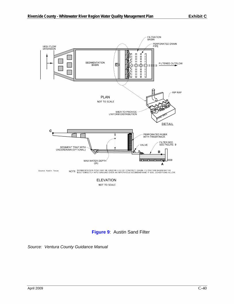
Riverside County - Whitewater River Region Water Quality Management Plan Exhibit C
April 2009 C-40
Figure 9: Austin Sand Filter
Source: Ventura County Guidance Manual
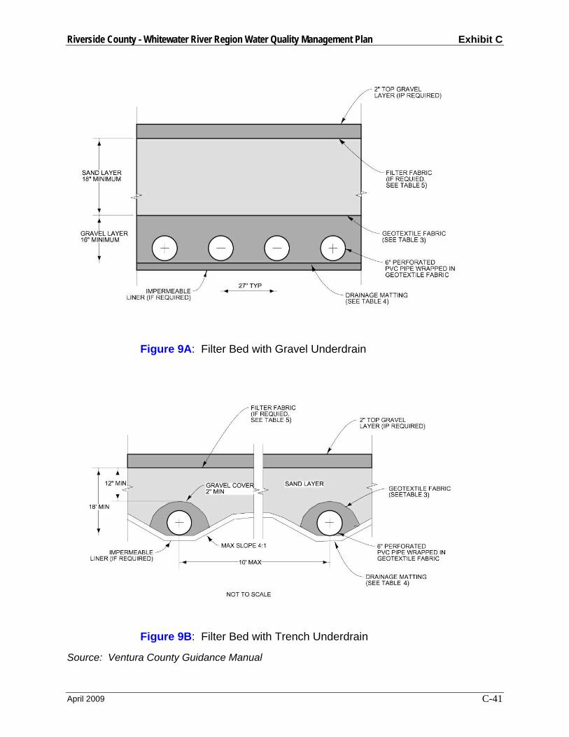
Riverside County - Whitewater River Region Water Quality Management Plan Exhibit C
April 2009 C-41
Figure 9A: Filter Bed with Gravel Underdrain
Figure 9B: Filter Bed with Trench Underdrain
Source: Ventura County Guidance Manual

Riverside County - Whitewater River Region Water Quality Management Plan Exhibit C
April 2009 C-42
Worksheet 7 Design Procedure Form for Austin Sand Filter Designer:__________________________________________________________ Company:_________________________________________________________ Date:_____________________________________________________________ Project:___________________________________________________________ Location:__________________________________________________________ 1. Determine Design Storage Volume
(Use Worksheet 1) a. Total Tributary Area (maximum
100) b. Design Storage Volume, VBMP
Atotal = __________ acres VBMP = __________ ft3
2. Maximum Water Height in
Sedimentation Basin* a. Invert elevation at connection to
storm drain system. b. Sand Filter invert elevation
(consider min. grade (1%) from storm drain). Point A, Figure 9.
c. Estimate filter depth or use min. (3’).
d. Top elevation of filter bed. Point B, Figure 9.
e. Surface elevation at BMP inlet. Point C, Figure 9.
f. Determine max. allowable height (2h) of water in the sedimentation basin using the elevation difference between points C and B. (min. 2’, max. 10’) 2h = [(C-B) – 1’ Freeboard]
Elev. Storm Drain = __________ ft Elev. Pt A = __________ ft Filter Depth = __________ ft Elev. Pt B = __________ ft Elev. Pt C = __________ ft 2h = ___________ ft
3. Size Sedimentation Basin
a. Find Sedimentation Basin Area, As As = VBMP / (2h)
b. Determine basin length and width, using a length to width ratio ≥ 2:1 As = 2 x W2 length = 2 x width
As = _________ ft2 width = _________ ft length = _________ ft
4. Size Filter Basin
a. Determine Filter Basin Area, Af Af = VBMP / 18
b. Determine Filter Basin Volume
Af = _________ ft2
Riverside County - Whitewater River Region Water Quality Management Plan Exhibit C
April 2009 C-43
Vf = Af x filter depth (part 2c)
c. Determine Required Volume, Vr Vr = 0.2 x VBMP
d. Check if Vr ≤ Vf If no, redesign with an increased filter depth or increase filter area.
Vf = _________ ft3 Vr = _________ ft3 Check Vr ≤ Vf _________
Notes: * Based on these elevations, is there a sufficient elevation drop to allow gravity flow from the outlet of the control measure to the storm drain system? If no, investigate alternative on-site locations for treatment control, consider another treatment control measure more suitable for site conditions, or contact the District to discuss on-site pumping requirements.

Riverside County - Whitewater River Region Water Quality Management Plan Exhibit C
April 2009 C-44
Delaware Sand Filter General
A Delaware sand filter is an underground filter consisting of two parallel concrete trenches divided by a close-spaced wall. Water enters the sedimentation trench through grated covers or a storm drain system. After this permanent pool fills, water overflows through the weir notches at the top of the dividing wall into the filter chamber. This assures that water enters the filter chamber as sheet flow and protects the sand bed from scouring. The permanent pool in the sedimentation chamber is dead storage, which allows heavier sediment to settle out and inhibits resuspension of particles from earlier storms. After passing through the filter bed, water flows into a clearwell area and into the storm drain system. Flows greater than the design volume can enter the sedimentation trench as long as an overflow weir is installed into the clearwell. A Delaware filter can treat tributary areas up to 5 acres.
Delaware Sand Filter Basin Design Criteria:
Design Parameter Unit Design Criteria 1
Design Volume ft3 VBMP Maximum tributary area acre 5 Weir height between sedimentation chamber and sand filter
in 2” above sand filter bed
Draw-down time hrs 48 3 Minimum gravel depth over sand in 2 Minimum sand depth, ds in 18 Minimum gravel underdrain depth, dg in 16 Filter Coefficient, k ft/day 2 Top layer and underdrain gravel size in 0.5 to 2-inch diameter
stone Sand size - ASTM C33 concrete
sand Slope of top layer % 0 (horizontal) Minimum slope of underdrain or bottom of filter % 0.5% Minimum size underdrain - 6” PVC schedule 40 Minimum size diameter perforation in 3/8 Minimum number of holes per row - 6 Minimum spacing between rows in 6 Minimum weephole diameter in 3 Minimum spacing between weepholes in 9 (center to center) Sedimentation chamber and sand filter width in 18 to 30
1 Ventura County’s Technical Guidance Manual for Stormwater Quality Control Measures 2 City of Modesto’s Guidance Manual for New Development Stormwater Quality Control Measures 3 CA Stormwater BMP Handbook for New Development and Significant Redevelopment 4 Riverside County DAMP Supplement A Attachment

Riverside County - Whitewater River Region Water Quality Management Plan Exhibit C
April 2009 C-45
Delaware Sand Filter Design Procedure 1. Design Storage Volume
Use Worksheet 1- Design Procedure Form for Design Storage Volume, VBMP.
2. Maximum Water Depth Determine maximum allowable height (2h) of water that can pond over the filter based on elevation differences between the filter bed top and the BMP inlet. An overflow weir should be designed to allow flows greater than the design volume to pass into the clearwell.
3. Sand Filter/Sediment Chamber Surface Area
The DSF shell must have the capacity to accept and store the design volume. The dimensions are sized to provide a filter area that processes the design volume in the desired time frame (48 hrs). The areas of the sedimentation chamber As and filter bed Af are typically set equal. The required areas are calculated as follows depending on the maximum depth of water above the filter bed:
a. If 2h < 2.67 ft Use: As = Af = VBMP / (4.1h + 0.9) b. If 2h > 2.67 ft Use: As = Af = [VBMP x ds] / [k (h + ds) t]
where: VBMP = Design Volume ft3 Af = filter bed surface area, ft2 As = sediment chamber surface area, ft2 ds = depth of sand, ft k = filter coefficient 0.0833 ft/hr h = one half of maximum allowable water depth (2h), ft t = 48 hour draw-down time
4. Select sediment chamber and filter width (Ws = Wf)
Site considerations usually dictate the final dimensions of the facility. Sediment chambers and filter chambers are normally 18-30 inches wide. Use of standard grates requires a width of 26 inches.
5. Sediment Chamber and Filter Length
Ls = Lf = Af / Wf
Round length up as appropriate and compute adjusted Area
As = Af = Wf x Lf
6. Storage volume in Filter Voids Vv
Vv = Af x 0.4(ds + dg) {assume 40% voids} Where dg = underdrain gravel depth
Riverside County - Whitewater River Region Water Quality Management Plan Exhibit C
April 2009 C-46
7. Volume of flow through filter during filling, VQ VQ = [k x Af x (ds + h) x tv] / [ds]
Use tv = 1 hour to fill voids 8. Net Volume Required to be Stored in Chambers Awaiting Filtration Vr
Vr = VBMP – Vv – VQ
9. Available Storage in Chambers Va
Va = 2h(Af + As)
If Va ≥ Vr, proceed with design If Va< Vr, adjust width and/or length and repeat steps 3-8.
10. Filter Bed
a. Top Gravel Layer The washed gravel layer at the top of the filter should be two inches thick, composed of stone 0.5 to 2.0 inches in diameter. In areas with high sediment load (TSS concentration >200 mg/L), the two-inch layer of stone on top of the sand filter should be underlain with filter fabric meeting the specifications in Table 8.
b. Sand Layer The sand layer should be a minimum depth of 18 inches consisting of ASTM C33 concrete sand. A layer of geotextile fabric meeting the specifications in Table 6 must separate the sand and gravel layer below.
c. Gravel Layer The gravel layer surrounding the collector pipes should be at least 16 inches thick and be composed of 0.5 to 2-inch diameter stone and provide at least two inches of cover over the tops of the drainage pipes.
10. Underdrain Piping
The underdrain piping should follow the same criteria and design as the Austin Sand Filter. Shallow rectangular drain tiles may be fabricated from such materials as fiberglass structural channels, saving several inches of filter depth. Drain tiles should be in two-foot lengths and spaced to provide gaps 1/8-inch less than the smallest gravel sizes on all four sides. Sections of tile may be cast in the dividing wall between the filter and the clearwell to provide shallow outflow orifices.
11. Weep Holes
In addition to the underdrain pipes, weepholes should be installed between the filter chamber and the clearwell to provide relief in case of pipe clogging. The weepholes should be three (3) inches in diameter. Minimum spacing should be nine (9) inches center to center. The openings on the filter side of the dividing wall should be covered to the width of the trench with 12-inch high plastic hardware cloth of ¼ inch mesh or galvanized steel wire, minimum wire diameter 0.03-inch, number 4 mesh
Riverside County - Whitewater River Region Water Quality Management Plan Exhibit C
April 2009 C-47
hardware cloth anchored firmly to the dividing wall structure and folded a minimum of six (6) inches back under the bottom stone.
12. Grates and Covers
Grates and cast steel covers are designed to take the same wheel loads as the adjacent pavement. Where possible, use standard grates to reduce costs. Grates and covers should be supported by a galvanized steel perimeter frame.
13. Hoods/Traps
In applications where trapping of hydrocarbons and other floating pollutants is required, large-storm overflow weirs should be equipped with a 10-gauge aluminum hood or commercially available catch basin trap. The hood or trap should extend a minimum of one foot into the permanent pool.
14. Dewatering Drain
A six inch diameter dewatering drain with gate valve is to be installed at the top of the stone/sand filter bed through the partition separating the filter chamber from the clearwell chamber.
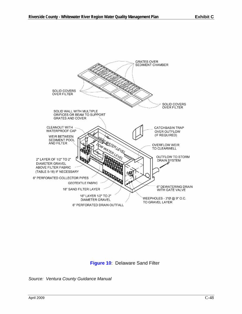
Riverside County - Whitewater River Region Water Quality Management Plan Exhibit C
April 2009 C-48
Figure 10: Delaware Sand Filter
Source: Ventura County Guidance Manual
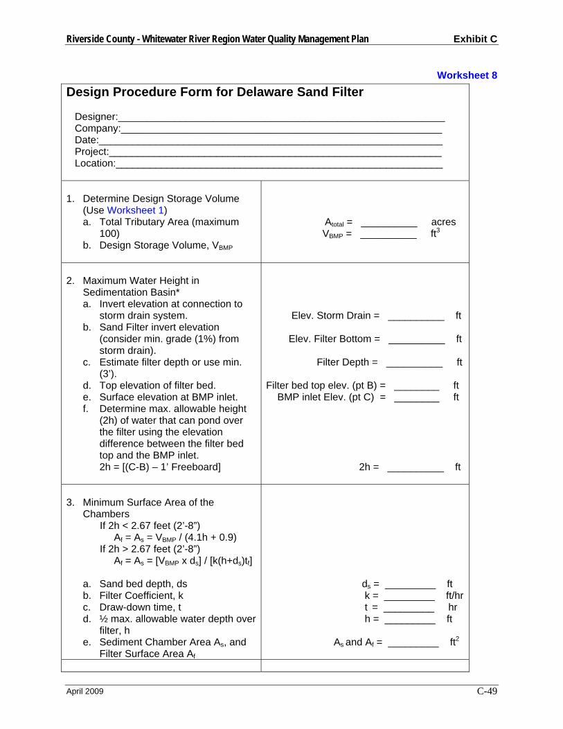
Riverside County - Whitewater River Region Water Quality Management Plan Exhibit C
April 2009 C-49
Worksheet 8 Design Procedure Form for Delaware Sand Filter Designer:__________________________________________________________ Company:_________________________________________________________ Date:_____________________________________________________________ Project:___________________________________________________________ Location:__________________________________________________________ 1. Determine Design Storage Volume
(Use Worksheet 1) a. Total Tributary Area (maximum
100) b. Design Storage Volume, VBMP
Atotal = __________ acres VBMP = __________ ft3
2. Maximum Water Height in
Sedimentation Basin* a. Invert elevation at connection to
storm drain system. b. Sand Filter invert elevation
(consider min. grade (1%) from storm drain).
c. Estimate filter depth or use min. (3’).
d. Top elevation of filter bed. e. Surface elevation at BMP inlet. f. Determine max. allowable height
(2h) of water that can pond over the filter using the elevation difference between the filter bed top and the BMP inlet. 2h = [(C-B) – 1’ Freeboard]
Elev. Storm Drain = __________ ft Elev. Filter Bottom = __________ ft Filter Depth = __________ ft Filter bed top elev. (pt B) = ________ ft BMP inlet Elev. (pt C) = ________ ft 2h = __________ ft
3. Minimum Surface Area of the
Chambers If 2h < 2.67 feet (2’-8”) Af = As = VBMP / (4.1h + 0.9) If 2h > 2.67 feet (2’-8”) Af = As = [VBMP x ds] / [k(h+ds)tf] a. Sand bed depth, ds b. Filter Coefficient, k c. Draw-down time, t d. ½ max. allowable water depth over
filter, h e. Sediment Chamber Area As, and
Filter Surface Area Af
ds = _________ ft k = _________ ft/hr t = _________ hr h = _________ ft As and Af = _________ ft2

Riverside County - Whitewater River Region Water Quality Management Plan Exhibit C
April 2009 C-50
4. Sediment Chamber and Filter Dimensions a. Select width (Ws = Wf = 18” to 30”) b. Filter length (Ls = Lf = Afm/Wf) c. Adjusted length (rounded) d. Adjusted area (As = Af = Wf x Lf)
Ws = Wf = _________ ft Ls = Lf = _________ ft Ls = Lf = _________ ft As = Af = _________ ft2
5. System Storage Volume
a. Storage in filter voids (Vv = Af x 0.4(dg +ds)
b. Volume of flow through filter (VQ = k x Af(ds+h) 1hr / ds)
c. Required net storage (Vr = VBMP–Vv–VQ)
d. Available storage (Va = 2h(Af +As)) If Va ≥ Vr, sizing is complete If Va < Vr, repeat steps 4 and 5
Vv = _________ ft3 VQ = _________ ft3 Vr = _________ ft3 Va = _________ ft3
Check Vr ≥ Va _________
Notes: * Based on these elevations, is there a sufficient elevation drop to allow gravity flow from the outlet of the control measure to the storm drain system? If no, investigate alternative on-site locations for treatment control, consider another treatment control measure more suitable for site conditions, or contact the District to discuss on-site pumping requirements.
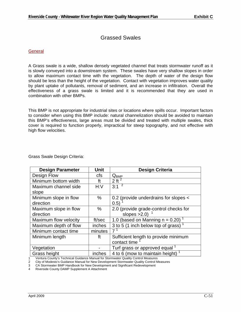
Riverside County - Whitewater River Region Water Quality Management Plan Exhibit C
April 2009 C-51
Grassed Swales General
A Grass swale is a wide, shallow densely vegetated channel that treats stormwater runoff as it is slowly conveyed into a downstream system. These swales have very shallow slopes in order to allow maximum contact time with the vegetation. The depth of water of the design flow should be less than the height of the vegetation. Contact with vegetation improves water quality by plant uptake of pollutants, removal of sediment, and an increase in infiltration. Overall the effectiveness of a grass swale is limited and it is recommended that they are used in combination with other BMPs.
This BMP is not appropriate for industrial sites or locations where spills occur. Important factors to consider when using this BMP include: natural channelization should be avoided to maintain this BMP’s effectiveness, large areas must be divided and treated with multiple swales, thick cover is required to function properly, impractical for steep topography, and not effective with high flow velocities.
Grass Swale Design Criteria:
Design Parameter Unit Design Criteria
Design Flow cfs QBMP Minimum bottom width ft 2 ft 2 Maximum channel side slope
H:V 3:1 2
Minimum slope in flow direction
% 0.2 (provide underdrains for slopes < 0.5) 1
Maximum slope in flow direction
% 2.0 (provide grade-control checks for slopes >2.0) 1
Maximum flow velocity ft/sec 1.0 (based on Manning n = 0.20) 1 Maximum depth of flow inches 3 to 5 (1 inch below top of grass) 1 Minimum contact time minutes 7 1 Minimum length ft Sufficient length to provide minimum
contact time 1 Vegetation - Turf grass or approved equal 1 Grass height inches 4 to 6 (mow to maintain height) 1
1 Ventura County’s Technical Guidance Manual for Stormwater Quality Control Measures 2 City of Modesto’s Guidance Manual for New Development Stormwater Quality Control Measures 3 CA Stormwater BMP Handbook for New Development and Significant Redevelopment 4 Riverside County DAMP Supplement A Attachment
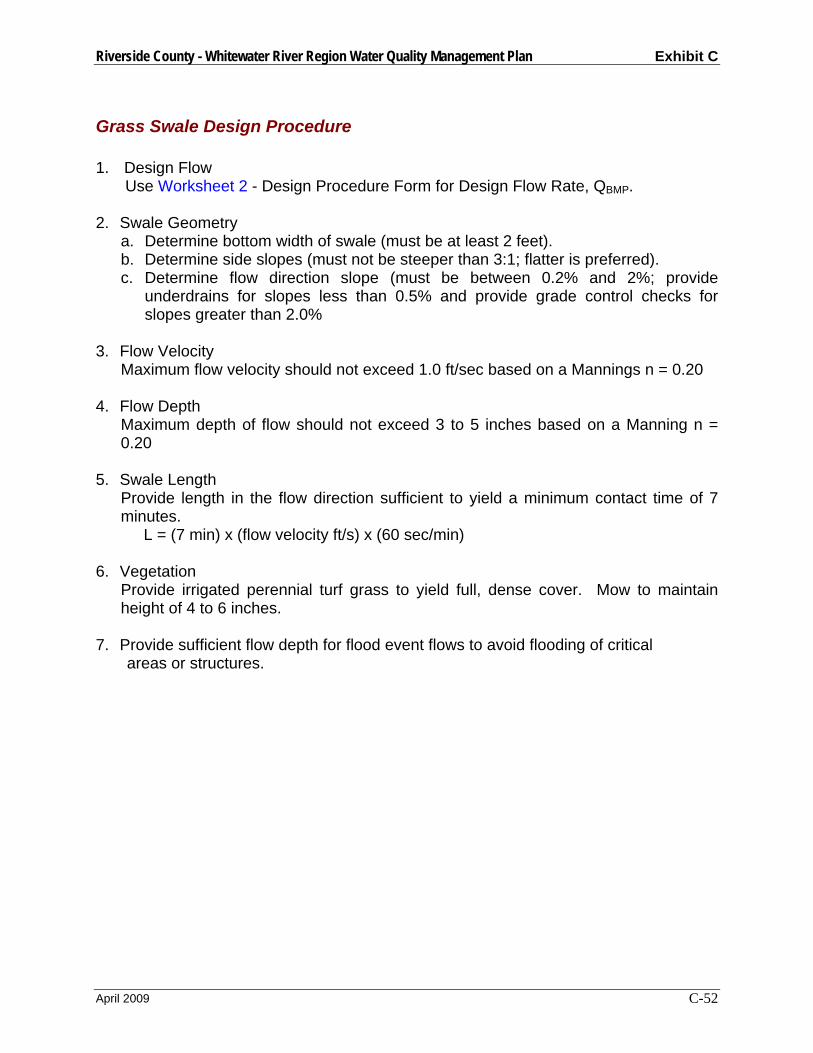
Riverside County - Whitewater River Region Water Quality Management Plan Exhibit C
April 2009 C-52
Grass Swale Design Procedure
1. Design Flow Use Worksheet 2 - Design Procedure Form for Design Flow Rate, QBMP.
2. Swale Geometry a. Determine bottom width of swale (must be at least 2 feet). b. Determine side slopes (must not be steeper than 3:1; flatter is preferred). c. Determine flow direction slope (must be between 0.2% and 2%; provide
underdrains for slopes less than 0.5% and provide grade control checks for slopes greater than 2.0%
3. Flow Velocity
Maximum flow velocity should not exceed 1.0 ft/sec based on a Mannings n = 0.20
4. Flow Depth Maximum depth of flow should not exceed 3 to 5 inches based on a Manning n = 0.20
5. Swale Length Provide length in the flow direction sufficient to yield a minimum contact time of 7 minutes.
L = (7 min) x (flow velocity ft/s) x (60 sec/min) 6. Vegetation
Provide irrigated perennial turf grass to yield full, dense cover. Mow to maintain height of 4 to 6 inches.
7. Provide sufficient flow depth for flood event flows to avoid flooding of critical areas or structures.
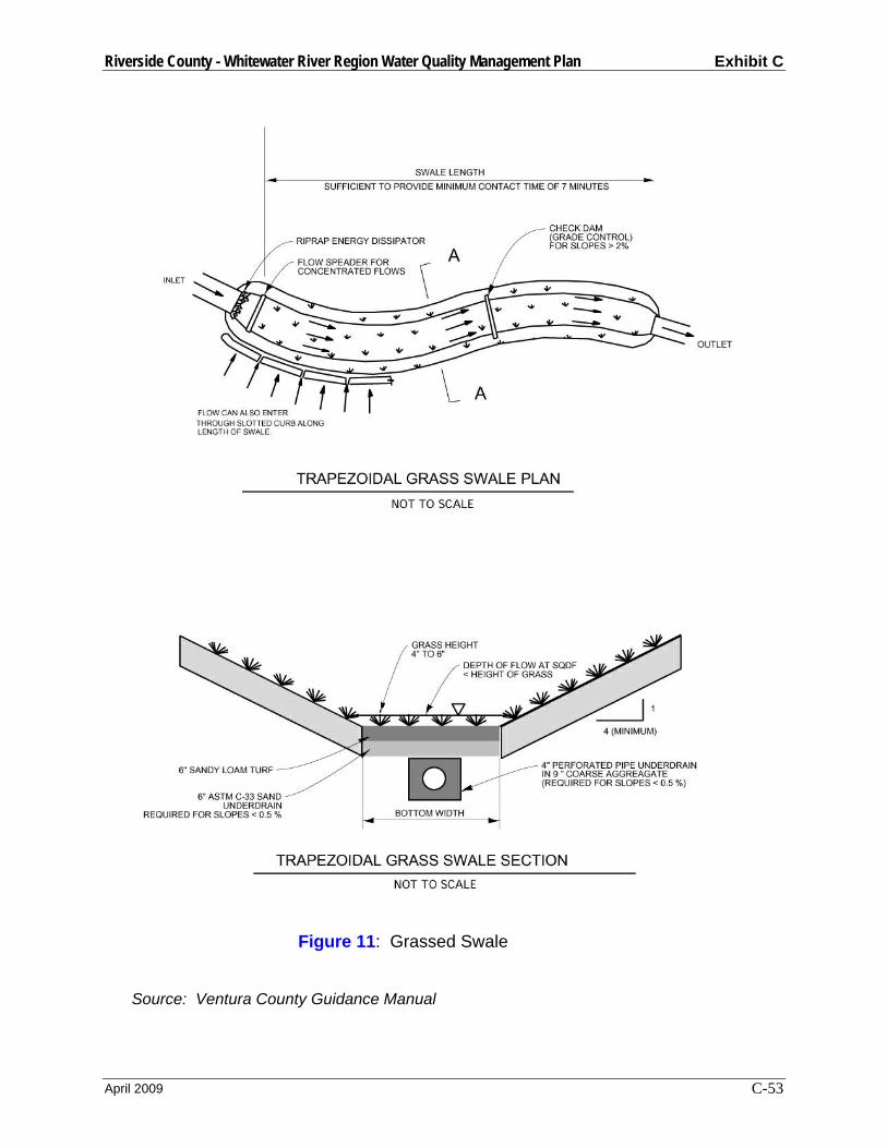
Riverside County - Whitewater River Region Water Quality Management Plan Exhibit C
April 2009 C-53
Figure 11: Grassed Swale Source: Ventura County Guidance Manual

Riverside County - Whitewater River Region Water Quality Management Plan Exhibit C
April 2009 C-54
Worksheet 9 Design Procedure Form for Grassed Swale Designer:__________________________________________________________ Company:_________________________________________________________ Date:_____________________________________________________________ Project:___________________________________________________________ Location:__________________________________________________________ 1. Determine Design Flow
(Use Worksheet 2)
QBMP = __________ cfs
2. Swale Geometry
a. Swale bottom width (b) b. Side slope (z) c. Flow direction slope (s)
b = __________ ft z = __________ s = __________ %
3. Design flow velocity (Manning n = 0.2)
v = __________ ft/s
4. Depth of flow (D)
D = __________ ft
5. Design Length (L) L = (7 min) x (flow velocity, ft/sec) x 60
L = __________ ft
6. Vegetation (describe)
8. Outflow Collection (check type used or describe “other”)
___ Grated Inlet’ ___ Infiltration Trench ___ Underdrain ___ Other__________________________
Notes:
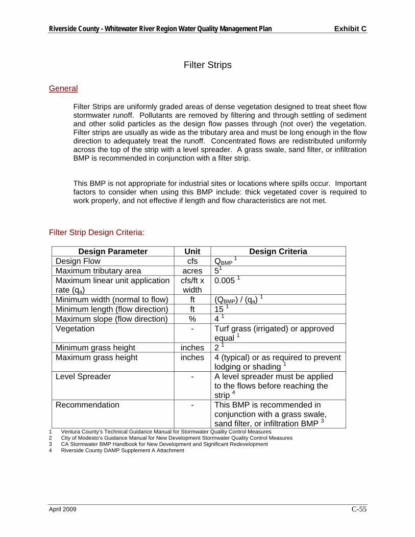
Riverside County - Whitewater River Region Water Quality Management Plan Exhibit C
April 2009 C-55
Filter Strips General
Filter Strips are uniformly graded areas of dense vegetation designed to treat sheet flow stormwater runoff. Pollutants are removed by filtering and through settling of sediment and other solid particles as the design flow passes through (not over) the vegetation. Filter strips are usually as wide as the tributary area and must be long enough in the flow direction to adequately treat the runoff. Concentrated flows are redistributed uniformly across the top of the strip with a level spreader. A grass swale, sand filter, or infiltration BMP is recommended in conjunction with a filter strip.
This BMP is not appropriate for industrial sites or locations where spills occur. Important factors to consider when using this BMP include: thick vegetated cover is required to work properly, and not effective if length and flow characteristics are not met.
Filter Strip Design Criteria:
Design Parameter Unit Design Criteria Design Flow cfs QBMP
1 Maximum tributary area acres 51 Maximum linear unit application rate (qa)
cfs/ft x width
0.005 1
Minimum width (normal to flow) ft (QBMP) / (qa) 1 Minimum length (flow direction) ft 15 1 Maximum slope (flow direction) % 4 1 Vegetation - Turf grass (irrigated) or approved
equal 1 Minimum grass height inches 2 1 Maximum grass height inches 4 (typical) or as required to prevent
lodging or shading 1 Level Spreader - A level spreader must be applied
to the flows before reaching the strip 4
Recommendation - This BMP is recommended in conjunction with a grass swale, sand filter, or infiltration BMP 3
1 Ventura County’s Technical Guidance Manual for Stormwater Quality Control Measures 2 City of Modesto’s Guidance Manual for New Development Stormwater Quality Control Measures 3 CA Stormwater BMP Handbook for New Development and Significant Redevelopment 4 Riverside County DAMP Supplement A Attachment
Riverside County - Whitewater River Region Water Quality Management Plan Exhibit C
April 2009 C-56
Filter Strip Design Procedure
1. Design Flow Use Worksheet 2 - Design Procedure Form for Design Flow Rate, QBMP.
2. Minimum Width Calculate minimum width of the grass strip filter (Wm) normal to flow direction: Wm = (QBMP)/(qa) Wm = (QBMP)/0.005 cfs/ft (minimum)
3. Minimum Length Length of the grass strip filter (Lm) in the direction of flow shall not be less than 15 feet. Lm = 15 feet (minimum)
4. Maximum Slope Slope of the ground in the direction of flow shall not be greater than 4 percent.
5. Flow Distribution Incorporate a device at the upstream end of the filter strip to evenly distribute flows along the top width, such as slotted curbing, modular block porous pavement, or other spreader devices. Concentrated flow delivered to the filter strip must be distributed evenly by means of a level spreader of similar concept.
6. Vegetation Provide irrigated perennial turf grass to yield full, dense cover. Submit a Landscape Plan for stormwater agency review. Plan shall be prepared by a landscape or other appropriate specialist and shall include a site plan showing location and type of vegetation. Mow grass to maintain height approximately between 2 and 4 inches.
7. Outflow Collection Provide a means for outflow collection and conveyance (e.g. grass channel/swale, storm sewer, street gutter).
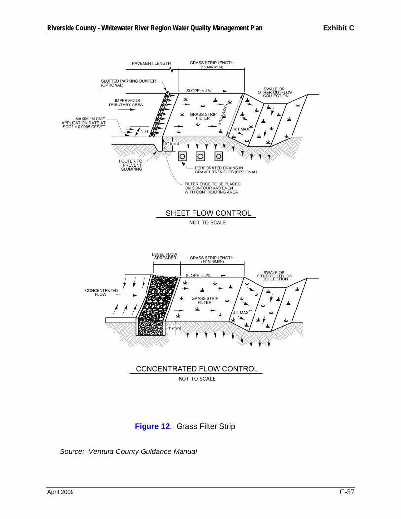
Riverside County - Whitewater River Region Water Quality Management Plan Exhibit C
April 2009 C-57
Figure 12: Grass Filter Strip Source: Ventura County Guidance Manual

Riverside County - Whitewater River Region Water Quality Management Plan Exhibit C
April 2009 C-58
Worksheet 10 Design Procedure Form for Filter Strip Designer:__________________________________________________________ Company:_________________________________________________________ Date:_____________________________________________________________ Project:___________________________________________________________ Location:__________________________________________________________
1. Determine Design Flow (Use Worksheet 2)
QBMP = __________ cfs
2. Design Width
Wm = (QBMP)/0.005 cfs/ft
Wm = __________ ft
3. Design Length (15 ft minimum)
Lm = __________ ft
4. Design Slope (4 % maximum)
SD = __________ %
5. Flow Distribution (check type used or describe “other”)
___ slotted curbing ___ Modular Block Porous Pavement ___ Level Spreader ___other___________________________
6. Vegetation (describe)
5. Outflow Collection (check type used or describe “other”)
___ Grass Swale ___ Street Gutter ___ Storm Drain ___ Underdrain ___ Other__________________________
Notes:

Riverside County - Whitewater River Region Water Quality Management Plan Exhibit C
April 2009 C-59
Water Quality Inlets General A water quality inlet is a device that removes oil and grit from stormwater runoff before the water enters the stormdrain system. It consists of one or more chambers that promote sedimentation of coarse materials and separation of free oil from stormwater. Manufacturers have created a variety of configurations to accomplish this. A specific model can be selected from the manufactuer based on the design flow rate. A water quality inlet is generally used for pretreatment before discharging into another type of BMP.
Water Quality Inlet Design Criteria:
Design Parameter Unit Design Criteria Design Flow cfs QBMP Maximum Tributary Area acres 1 4 Clean-out Schedule - At least twice per year 4
1 Ventura County’s Technical Guidance Manual for Stormwater Quality Control Measures 2 City of Modesto’s Guidance Manual for New Development Stormwater Quality Control Measures 3 CA Stormwater BMP Handbook for New Development and Significant Redevelopment 4 Riverside County DAMP Supplement A Attachment
Water Quailty Inlet Design Procedure
1. Design Flow Use Worksheet 2 - Design Procedure Form for Design Flow Rate, QBMP.
2. Select Model Select a water quality inlet model that will appropriately treat the design flow using manufacturer specifications.
3. Maintenance Requirements
In order to maintain its ability to treat stormwater, the inlet must be cleaned at least twice a year. Arrangements should be made to do this.

Riverside County - Whitewater River Region Water Quality Management Plan Exhibit C
April 2009 C-60
Worksheet 11 Design Procedure Form for Water Quality Inlets Designer:__________________________________________________________ Company:_________________________________________________________ Date:_____________________________________________________________ Project:___________________________________________________________ Location:__________________________________________________________
1. Determine Design Flow Rate (Use Worksheet 2)
QBMP = __________ cfs
2. Water Quality Inlet
Manufacturer Name Model Flow Capacity of Model Please include a technical sheet from the manufacturer with information on this model.
Make ___________________ Model ___________________ Capacity ____________ cfs
Notes:

Riverside County - Whitewater River Region Water Quality Management Plan Exhibit C
April 2009 C-61
REFERENCES California Stormwater Quality Association, January 2003. Stormwater Best Management Practice Handbook for New Development and Redevelopment, prepared by Camp Dresser & McKee and Larry Walker Associates City of Modesto, Operations and Maintenance Department, January 2001. Guidance Manual for New Development Stormwater Quality Control Measures Attachment to Supplement “A” of the Riverside County Drainage Area Management Plans , April 1996. Selection and Design of Stormwater Quality Controls, prepared by Riverside County Flood Control and Water Conservation District Ventura Countywide Stormwater Quality Management Program July 2002. Technical Guidance Manual for Stormwater Quality Control Measures
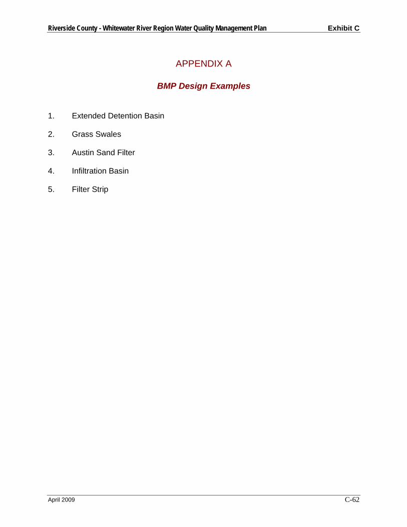
Riverside County - Whitewater River Region Water Quality Management Plan Exhibit C
April 2009 C-62
APPENDIX A
BMP Design Examples 1. Extended Detention Basin
2. Grass Swales
3. Austin Sand Filter
4. Infiltration Basin
5. Filter Strip
Whitewater River Region WQMP Public Review Draft
April 2009
Exhibit D
Runoff Coefficients for Urban Soil Types
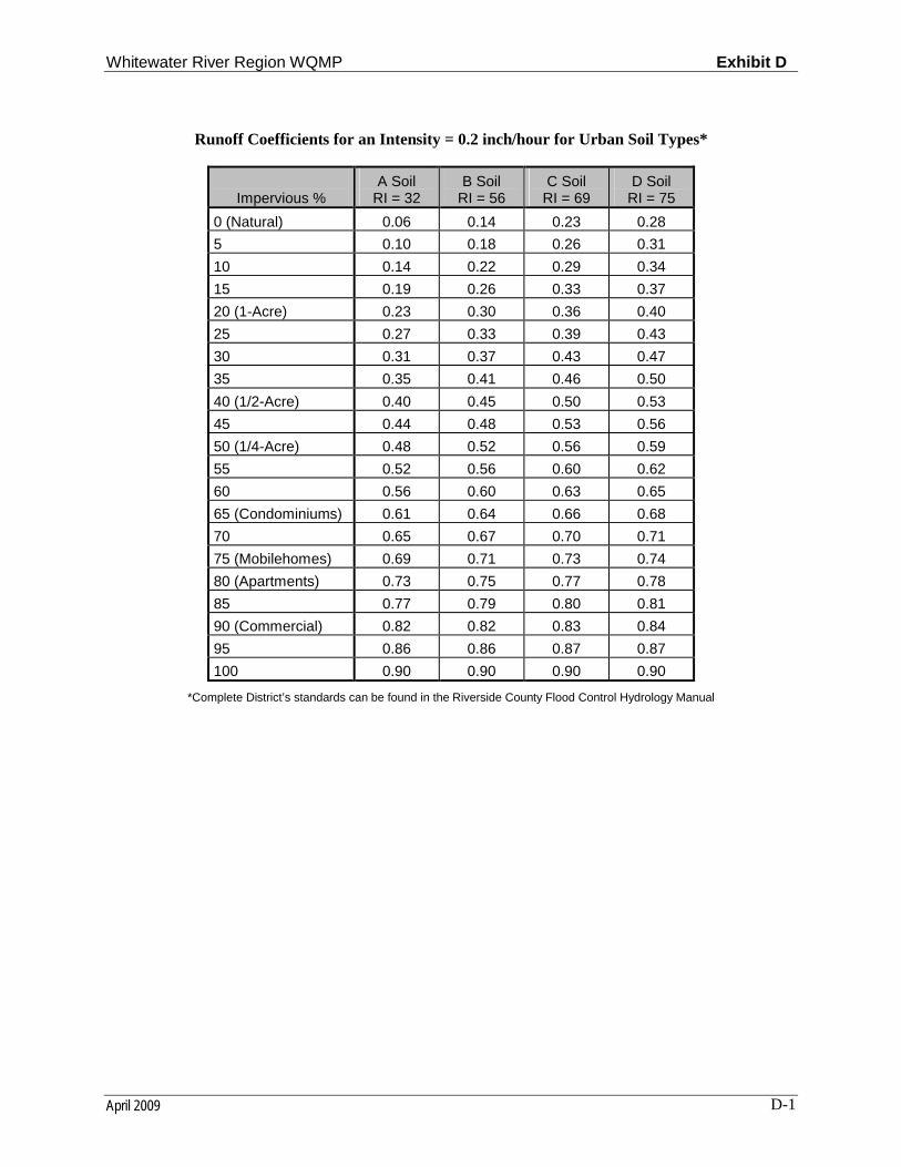
Whitewater River Region WQMP Exhibit D
April 2009 D-1
Runoff Coefficients for an Intensity = 0.2 inch/hour for Urban Soil Types*
Impervious %A Soil
RI = 32B Soil
RI = 56C Soil
RI = 69D Soil
RI = 75
0 (Natural) 0.06 0.14 0.23 0.28
5 0.10 0.18 0.26 0.31
10 0.14 0.22 0.29 0.34
15 0.19 0.26 0.33 0.37
20 (1-Acre) 0.23 0.30 0.36 0.40
25 0.27 0.33 0.39 0.43
30 0.31 0.37 0.43 0.47
35 0.35 0.41 0.46 0.50
40 (1/2-Acre) 0.40 0.45 0.50 0.53
45 0.44 0.48 0.53 0.56
50 (1/4-Acre) 0.48 0.52 0.56 0.59
55 0.52 0.56 0.60 0.62
60 0.56 0.60 0.63 0.65
65 (Condominiums) 0.61 0.64 0.66 0.68
70 0.65 0.67 0.70 0.71
75 (Mobilehomes) 0.69 0.71 0.73 0.74
80 (Apartments) 0.73 0.75 0.77 0.78
85 0.77 0.79 0.80 0.81
90 (Commercial) 0.82 0.82 0.83 0.84
95 0.86 0.86 0.87 0.87
100 0.90 0.90 0.90 0.90
*Complete District’s standards can be found in the Riverside County Flood Control Hydrology Manual
Whitewater River Region WQMP Public Review Draft
April 2009
Exhibit E
Typical Requirements for Common Maintenance Mechanisms

Whitewater River Region WQMP Exhibit E
April 2009 E-1
Typical Requirements for Common Maintenance Mechanisms
1. Public entity maintenance: The Permittee may approve a public or acceptable quasi-public entity (e.g., the Riverside County Flood Control District, or annex to an existing assessment district, an existing utility district, a state or federal resource agency, or a conservation conservancy) to assume responsibility for operation, maintenance, repair and replacement of the BMP. Unless otherwise acceptable to individual Permittees, public entity maintenance agreements shall ensure estimated costs are front-funded or reliably guaranteed, (e.g., through a trust fund, assessment district fees, bond, letter of credit or similar means). In addition, the Permittees may seek protection from liability by appropriate releases and indemnities.
The Permittee shall have the authority to approve Urban Runoff BMPs proposed for transfer to any other public entity within its jurisdiction before installation. The Permittee shall be involved in the negotiation of maintenance requirements with any other public entities accepting maintenance responsibilities within their respective jurisdictions; and in negotiations with the resource agencies responsible for issuing permits for the construction and/or maintenance of the facilities. The Permittee must be identified as a third party beneficiary empowered to enforce any such maintenance agreement within their respective jurisdictions.
2. Project proponent agreement to maintain Urban Runoff BMPs: The Permittee may enter into a contract with the project proponent obliging the project proponent to maintain, repair and replace the Urban Runoff BMP as necessary into perpetuity. Security or a funding mechanism with a “no sunset” clause may be required.
3. Assessment districts: The Permittee may approve an Assessment District or other funding mechanism created by the project proponent to provide funds for Urban Runoff BMP maintenance, repair and replacement on an ongoing basis. Any agreement with such a District shall be subject to the Public Entity Maintenance Provisions above.
4. Lease provisions: In those cases where the Permittee holds title to the land in question, and the land is being leased to another party for private or public use, the Permittee may assure Urban Runoff BMP maintenance, repair and replacement through conditions in the lease.
5. Conditional use permits: For discretionary projects only, the Permittee may assure maintenance of Urban Runoff BMPs through the inclusion of maintenance conditions in the conditional use permit. Security may be required.
6. Alternative mechanisms: The Permittee may accept alternative maintenance mechanisms if such mechanisms are as protective as those listed above.

Whitewater River Region WQMP Public Review Draft
April 2009
Exhibit F
Sample Covenant and Agreement

Whitewater River Region WQMP Exhibit F
April 2009 F-1
Example Covenant and Agreement
Water Quality Management Plan and Urban Runoff BMP Transfer, Access and Maintenance Agreement (adapted from documents from the Ventura County Stormwater Management Program)
Recorded at the request of:
City of ________________________________________________________
After recording, return to:
City of ________________________________________________________
City Clerk _____________________________________________________
Water Quality Management Plan and Urban Runoff BMPTransfer, Access and Maintenance Agreement
OWNER: ____________________________________________________
PROPERTY ADDRESS: ________________________________________
________________________________________
APN: ________________________________________________________
THIS AGREEMENT is made and entered into in
___________________________, California, this _______ day of
__________________ , by and between
_______________________________________________, herein after
Whitewater River Region WQMP Exhibit F
April 2009 F-2
referred to as “Owner” and the CITY OF _____________________________, a municipal corporation, located in the County of Riverside, State of California hereinafter referred to as “CITY”;
WHEREAS, the Owner owns real property (“Property”) in the City of
________________________, County of Riverside, State of California, more specifically described in Exhibit “A” and depicted in Exhibit “B”, each of which exhibits is attached hereto and incorporated herein by this reference;
WHEREAS, at the time of initial approval of development project known as
________________________________________ within the Property described herein, the City required the project to employ Best Management Practices, hereinafter referred to as “BMPs,” to minimize pollutants in urban runoff;
WHEREAS, the Owner has chosen to install and/or implement BMPs as described in the Water Quality Management Plan, on file with the City, hereinafter referred to as “WQMP”, to minimize pollutants in urban runoff and to minimize other adverse impacts of urban runoff;
WHEREAS, said WQMP has been certified by the Owner and reviewed and approved by the City;
WHEREAS, said BMPs, with installation and/or implementation on private property and draining only private property, are part of a private facility with all maintenance or replacement, therefore, the sole responsibility of the Owner in accordance with the terms of this Agreement;
WHEREAS, the Owner is aware that periodic and continuous maintenance, including, but not necessarily limited to, filter material replacement and sediment removal, is required to assure peak performance of all BMPs in the WQMP and that, furthermore, such maintenance activity will require compliance with all Local, State, or Federal laws and regulations, including those pertaining to confined space and waste disposal methods, in effect at the time such maintenance occurs;
NOW THEREFORE, it is mutually stipulated and agreed as follows:
1. Owner hereby provides the City of City’s designee complete access, of any duration, to the BMPs and their immediate vicinity at any time, upon reasonable notice, or in the event of emergency, as determined by City’s Director of Public Works no advance notice, for the purpose of inspection, sampling, testing of the Device, and in case of emergency, to undertake all necessary repairs or other preventative measures at owner’s expense as provided in paragraph 3 below. City shall make every effort at all times to minimize or avoid interference with Owner’s use of the Property.
2. Owner shall use its best efforts diligently to maintain all BMPs in a manner assuring peak performance at all times. All reasonable precautions shall be exercised by Owner and Owner’s representative or contractor in the removal and extraction of any material(s) from the BMPs and the ultimate disposal of the material(s) in a manner consistent with all relevant laws and regulations in effect at the time. As may be requested from time to time by the City, the Owner shall provide the City with documentation identifying the material(s) removed, the quantity, and disposal destination.
Whitewater River Region WQMP Exhibit F
April 2009 F-3
3. In the event Owner, or its successors or assigns, fails to accomplish the necessary maintenance contemplated by this Agreement, within five (5) days of being given written notice by the City, the City is hereby authorized to cause any maintenance necessary to be done and charge the entire cost and expense to the Owner or Owner’s successors or assigns, including administrative costs, attorneys fees and interest thereon at the maximum rate authorized by the Civil Code from the date of the notice of expense until paid in full.
4. The City may require the owner to post security in form and for a time period satisfactory to the city to guarantee the performance of the obligations state herein. Should the Owner fail to perform the obligations under the Agreement, the City may, in the case of a cash bond, act for the Owner using the proceeds from it, or in the case of a surety bond, require the sureties to perform the obligations of the Agreement. As an additional remedy, the Director may withdraw any previous Urban Runoff-related approval with respect to the property on which BMPs have been installed and/or implemented until such time as Owner repays to City its reasonable costs incurred in accordance with paragraph 3 above.
5. This agreement shall be recorded in the Office of the Recorder of Riverside County, California, at the expense of the Owner and shall constitute notice to all successors and assigns of the title to said Property of the obligation herein set forth, and also a lien in such amount as will fully reimburse the City, including interest as herein above set forth, subject to foreclosure in event of default in payment.
6. In event of legal action occasioned by any default or action of the Owner, or its successors or assigns, then the Owner and its successors or assigns agree(s) to pay all costs incurred by the City in enforcing the terms of this Agreement, including reasonable attorney’s fees and costs, and that the same shall become a part of the lien against said Property.
7. It is the intent of the parties hereto that burdens and benefits herein undertaken shall constitute covenants that run with said Property and constitute a lien there against.
8. The obligations herein undertaken shall be binding upon the heirs, successors, executors, administrators and assigns of the parties hereto. The term “Owner” shall include not only the present Owner, but also its heirs, successors, executors, administrators, and assigns. Owner shall notify any successor to title of all or part of the Property about the existence of this Agreement. Owner shall provide such notice prior to such successor obtaining an interest in all or part of the Property. Owner shall provide a copy of such notice to the City at the same time such notice is provided to the successor.
9. Time is of the essence in the performance of this Agreement.
10. Any notice to a party required or called for in this Agreement shall be served in person, or by deposit in the U.S. Mail, first class postage prepaid, to the address set forth below. Notice(s) shall be deemed effective upon receipt, or seventy-two (72) hours after deposit in the U.S. Mail, whichever is earlier. A party may change a notice address only by providing written notice thereof to the other party.

Whitewater River Region WQMP Exhibit F
April 2009 F-4
IF TO CITY: IF TO OWNER:
IN WITNESS THEREOF, the parties hereto have affixed their signatures as of the date first written above.
APPROVED AS TO FORM: OWNER:
City Attorney
CITY OF
Name
Title
ATTEST:
City Clerk Date
Name
Title
OWNER:
Name
Title
NOTARIES ON FOLLOWING PAGE

Whitewater River Region WQMP Exhibit F
April 2009 F-5
EXHIBIT A(Legal Description)

Whitewater River Region WQMP Exhibit F
April 2009 F-6
EXHIBIT B(Map/Illustration)

Whitewater River Region WQMP Public Review Draft
April 2009
Exhibit G
Glossary
Whitewater River Region WQMP Exhibit G
April 2009 G-1
Best Management Practices (BMPs) – Defined in 40 CFR 122.2 as schedules of activities, prohibitions of practices, maintenance procedures, and other management practices to prevent or reduce the pollution of Waters of the U.S. BMPs also include treatment requirements, operating procedures and practices to control plant site runoff, spillage or leaks, sludge or waste disposal, or drainage from raw material storage. In the case of MS4 permits, BMPs are typically used in place of numeric effluent limits.
Hydrologic Conditions of Concern – Changes caused by a New Development or Redevelopment Project to Urban Runoff flow rates, velocities, durations and/or volumes that cause significant downstream erosion beyond the pre-development condition or cause significant adverse impacts to stream habitat.
Municipal Separate Storm Sewer System (MS4) – An MS4 is a conveyance or system of conveyances (including roads with drainage systems, municipal streets, catch basins, curbs, gutters, ditches, natural drainage features or channels, modified natural channels, man-made channels, or storm drains): (i) Owned or operated by a State, city town, borough, county, parish, district, association, or other public body (created by or pursuant to State law) having jurisdiction over disposal of sewage, industrial wastes, stormwater, or other wastes, including special districts under State law such as a sewer district, flood control district or drainage district, or similar entity, or an Indian tribe or an authorized Indian tribal organization, or designated and approved management agency under Section 208 of the CWA that discharges to Waters of the U.S.; (ii) Designated or used for collecting of conveying stormwater; (iii) Which is not a combined sewer; (iv) Which is not part of the POTW as defined at 40 CFR 122.26.
Historic and current developments make use of natural drainage patterns and features as conveyances for urban runoff. Urban streams used in this manner are part of the municipalities MS4 regardless of whether they are natural, man-made, or partially modified features. In these cases, the urban stream is both an MS4 and a receiving water.
New Development – New construction on a previously undisturbed parcel. New developments do not include routine maintenance to maintain original line and grade, hydraulic capacity, or original purpose of a facility, nor do they include emergency new developments required to protect public health and safety. Dischargers should confirm with Regional Board staff whether or not a particular routine maintenance activity is subject to Order No. R7-2008-0001.
Pollutants of Concern – For the purposes of the WQMP, those Urban Runoff pollutants generated by a New Development or Redevelopment project. Pollutants of Concern may include urban runoff pollutants typically associated with the proposed land use, legacy pollutants that are associated with the project site, project related pollutants for which Receiving Waters downstream of and proximate to the project are listed as impaired under CWA Section 303(d), and pollutants commonly associated with Urban Runoff. Finding 23 of the Whitewater River NPDES MS4 Permit provides a list of pollutants that may beassociated with Urban Runoff.
Priority Development Projects – A discretionary New Development or Redevelopment Project that falls into one of the Priority Development Project categories enumerated in Section F.1.c.iv of Order No. R7-2008-0001.
Receiving Water(s) – The receiving waters within the Permit Area
Redevelopment – A project where major modifications to an existing site or structure requiring a permit issued by a Permittee is undertaken. Redevelopment does not include routine maintenance to maintain original line and grade, hydraulic capacity, or original purpose of a facility, emergency Redevelopments required to protect public health and safety, interior remodeling, re-roofing, or parking lot maintenance. Dischargers should confirm with Regional Board staff whether or not a particular routine maintenance

Whitewater River Region WQMP Exhibit G
April 2009 G-2
activity is subject to Order No. R7-2008-0001. A Redevelopment project is not to be confused with the projects undertaken by a Redevelopment Agency.
Site Design BMPs – Any project design feature that reduces the creation or severity of potential pollutant sources or reduces the alteration of the project site’s natural flow regime. Redevelopment projects that are undertaken to remove pollutant sources (such as existing surface parking lots and other impervious surfaces) or to reduce the need for new roads and other impervious surfaces (as compared to conventional or low-density new development) by incorporating higher densities and/or mixed land uses into the project design, are also considered site design BMPs.
Source Control BMPs – In general, activities or programs to educate the public or provide low cost non-physical solutions, as well as facility design or practices aimed to limit the contact between pollutant sources and Urban Runoff or authorized non-stormwater. Examples include activity schedules, prohibitions of practices, street sweeping, facility maintenance, detection and elimination of illicit connections and illegal dumping, and other non-structural measures. Facility design examples include providing attached lids to trash containers, or roof or awning over material and trash storage areas to prevent direct contact between water and pollutants.
Structural BMPs – Physical facilities or controls which may include secondary containment, treatment measures, (e.g. first flush diversion, detention/retention basins, and oil/grease separators), run-off controls (e.g., grass swales, infiltration trenches/basins, etc.), and engineering and design modification of existing structures.
Treatment Control BMPs – Any engineered system designed and constructed to remove pollutants from urban runoff. Pollutant removal is achieved by simple gravity settling of particulate pollutants, filtration, biological uptake, media adsorption or any other physical, biological, or chemical process.
Urban Runoff – Urban Runoff includes those discharges from residential, commercial, industrial, and construction areas within the Whitewater River Region MS4 Permit Area and excludes discharges from feedlots, dairies, farms, POTWs and open space. Urban Runoff discharges consist of stormwater and non-stormwater surface runoff from drainage sub-areas with various, often mixed, land uses within all of the hydrologic drainage areas that discharge into the Waters of the U.S. In addition to Urban Runoff, the MS4s regulated by Order No. R7-2008-0001.receive flows from agricultural activities, open space, state and federal properties and other non-urban land uses not under the control of the Permittees. The quality of the discharges from the MS4s varies considerably and is affected by, among other things, past and present land use activities, basin hydrology, geography and geology, season, the frequency and duration of storm events, and the presence of past or present illegal and allowed disposal practices and illicit connections. The Permittees lack legal jurisdiction over discharges into their respective MS4 facilities from agricultural activities, California and federal facilities, utilities and special districts, Native American tribal lands, wastewater management agencies and other point and non-point source discharges otherwise permitted by or under the jurisdiction of the Regional Board. The Regional Board recognizes that the Permittees should not be held responsible for such facilities and/or discharges. Similarly, certain activities that generate pollutants present in Urban Runoff are beyond the ability of the Permittees to eliminate. Examples of these include operation of internal combustion engines, atmospheric deposition, brake pad wear, tire wear, residues from lawful application of pesticides, nutrient runoff from agricultural activities, and leaching of naturally occurring minerals from local geography.
Waters of the United States – Waters of the U.S. can broadly be defined as navigable surface waters and all tributary surface waters to navigable surface waters. Groundwater is not considered Waters of the U.S. As defined in 40 CFR 122.2, the Waters of the U.S. are defined as: (a) All waters, which are currently used, were used in the past, or may be susceptible to use in interstate or foreign commerce, including all waters which are subject to the ebb and flow of the tide; (b) All interstate waters, including
Whitewater River Region WQMP Exhibit G
April 2009 G-3
interstate “wetlands;” (c) All other waters such as intrastate lakes, rivers, streams (including intermittent streams), mudflats, sandflats, “wetlands,” sloughs, prairie potholes, wet meadows, playa lakes, or natural ponds the use, degradation or destruction of which would affect or could affect interstate or foreign commerce including any such waters: (1) Which are or could be used I interstate or foreign travelers for recreation or other purposes; (2) From which fish or shellfish are or could be taken and sold in interstate or foreign commerce; or (3) Which are used or could be used for industrial purposes by industries in interstate commerce; (d) All impoundments of waters otherwise defined as Waters of the U.S. under this definition; (e) Tributaries of waters identified in paragraphs (a) through (d) of this definition; (f) The territorial seas; and (g) “wetlands” adjacent to waters (other than waters that are themselves wetlands) identified in paragraphs (a) through (f) of this definition. Waters of the U.S. do not include prior converted cropland. Notwithstanding the determination of an area’s status as prior converted cropland by any other federal agency, for the purposes of the Clean Water Act, the final authority regarding the Clean Water Act jurisdiction remains with the United States Environmental Protection Agency.