Embed Size (px)
Citation preview

Appendix G Hydrology and Hydraulics
T E C H N I C A L M E M O R A N D U M
WT0629151011KWO CH2M HILL CANADA LIMITED • COMPANY PROPRIETARY 1
City of London Mud Creek Environmental Assessment Hydrologic and Hydraulic Modelling PREPARED FOR: City of London
COPY TO: Upper Thames River Conservation Authority
PREPARED BY: CH2M
DATE: July 13, 2016
PROJECT NUMBER: 652502
1.0 Introduction The Mud Creek Subwatershed (MCS) is located within the City of London (City) in an area that is predominantly urban development. Mud Creek functions as a key component in the management of stormwater in both the urban and natural areas of the subwatershed and provides habitat for many aquatic and terrestrial species. As such, the proper functioning of the creek for conveyance of stormwater runoff as well as for supporting areas of aquatic and terrestrial habitat are very important to the City and its residents.
Progressive environmental degradation of Mud Creek and flooding in various reaches of the creek including at Oxford Street has been occurring for more than 20 years. CH2M has been retained by the City to conduct a Schedule B Environmental Assessment (EA) of the MCS in order to develop an effective strategy that will successfully mitigate flooding concerns at Oxford Street and on adjacent private lands, provide environmental benefit to the Mud Creek subwatershed, and allow the City to move forward with further development in the MCS. In addition to the EA objectives, CH2M was also asked to develop a draft flood hazard analysis in the eastern (main) branch of Mud Creek that is part of the study area.
CH2M developed a methodology for hydrologic and hydraulic modelling that was applied in the Mud Creek EA to determine a preferred strategy for mitigating flooding concerns and for determining the flood hazard areas along the main channel.
The purpose of this Technical Memorandum (TM) is to explain how the two key models were developed; namely the Design Model and the Floodplain Model. The Design Model follows the industry standard for hydrologic/hydraulic stormwater modelling. The Floodplain Model is consistent with the methodology defined by the Ministry of Natural Resources and Forestry to assist Conservation Authorities to establish and administer the polices associated with the Regulatory Floodplain hazard limits. This TM explains how the models were developed, how data was exchanged between them and how the results were utilized in the assessment of both the preferred servicing alternative as detailed in the EA and in the flood hazard analysis.
2.0 Hydrologic Analysis This section describes the methods utilized to estimate the magnitude of surface water flows tributary to Mud Creek that were used for development of a preferred servicing alternative and for delineation of flood hazard limits associated with the main channel.
CITY OF LONDON MUD CREEK ENVIRONMENTAL ASSESSMENT HYDROLOGIC AND HYDRAULIC MODELLING
2 CH2M HILL CANADA LIMITED • COMPANY PROPRIETARY WT0629151011KWO
Hydrologic modelling was performed using PCSWMM 2016 Professional 2D (Version 6.2.2070), which utilizes the US-EPA Storm Water Management Model 5 engine for hydrologic and hydraulic routing calculations. PCSWMM is a commercially available interface for SWMM5 that was developed in Ontario and provides advanced integration with a GIS environment facilitating the ability to pre-process and manage model input/output data. It’s GIS engine works with the latest GIS data formats, and provides tools for streamlining model development and analysis in a wide range of applications. Models developed using PCSWMM are fully functional with the SWMM5 model package, which is available for free and updated on a regular basis. The hydrologic modelling approach is consistent with previous modelling of Mud Creek developed by the Upper Thames River Conservation Authority (UTRCA) for the purpose of flood hazard delineation, and with the approaches described in ‘Storm Water Management Model User’s Manual Volume 1’ (Rossman, 2016).
2.1 Model Development The basic steps to create a hydrology model include dividing the drainage area into logical smaller subcatchments, assigning hydrological runoff parameters to each subcatchment based on catchment characteristics, assigning appropriate connectivity to subcatchments using hydraulic elements, and applying the design precipitation to generate runoff from subcatchments.
2.1.1 Catchments This section describes assignment of catchment parameters including delineation, imperviousness, slope, infiltration, width, Manning’s roughness coefficients, and depression storage. A discussion of incorporating dual drainage into the model is also provided.
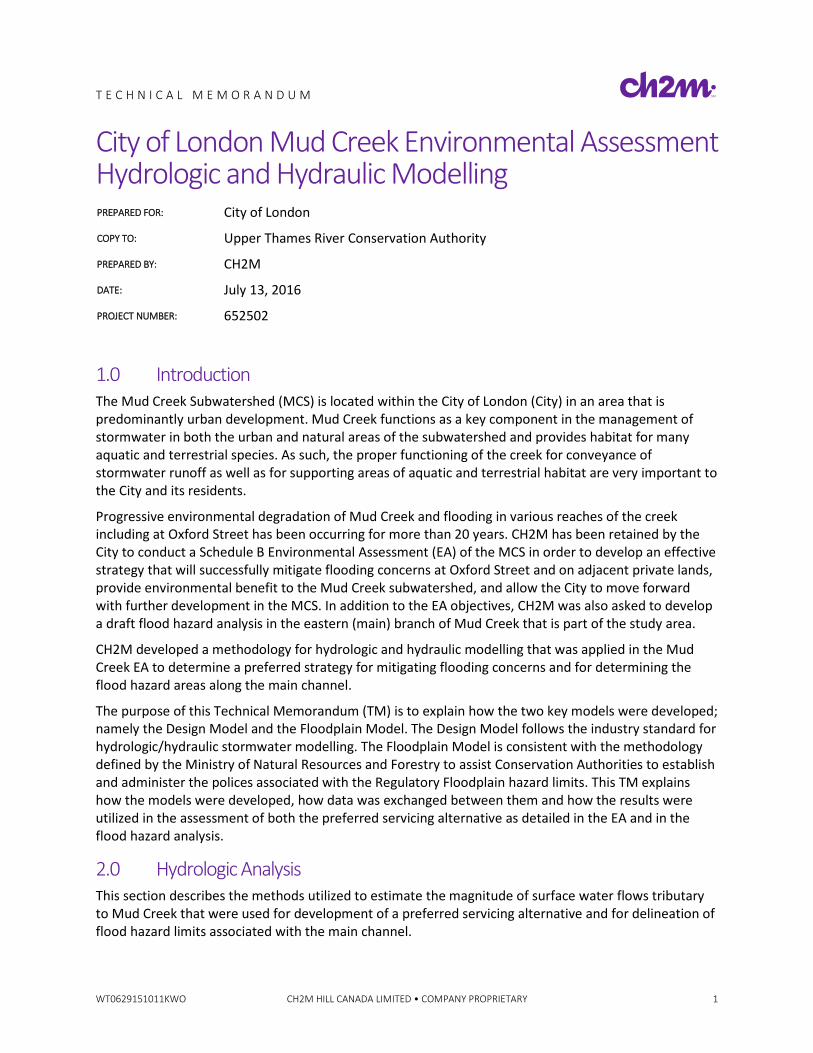
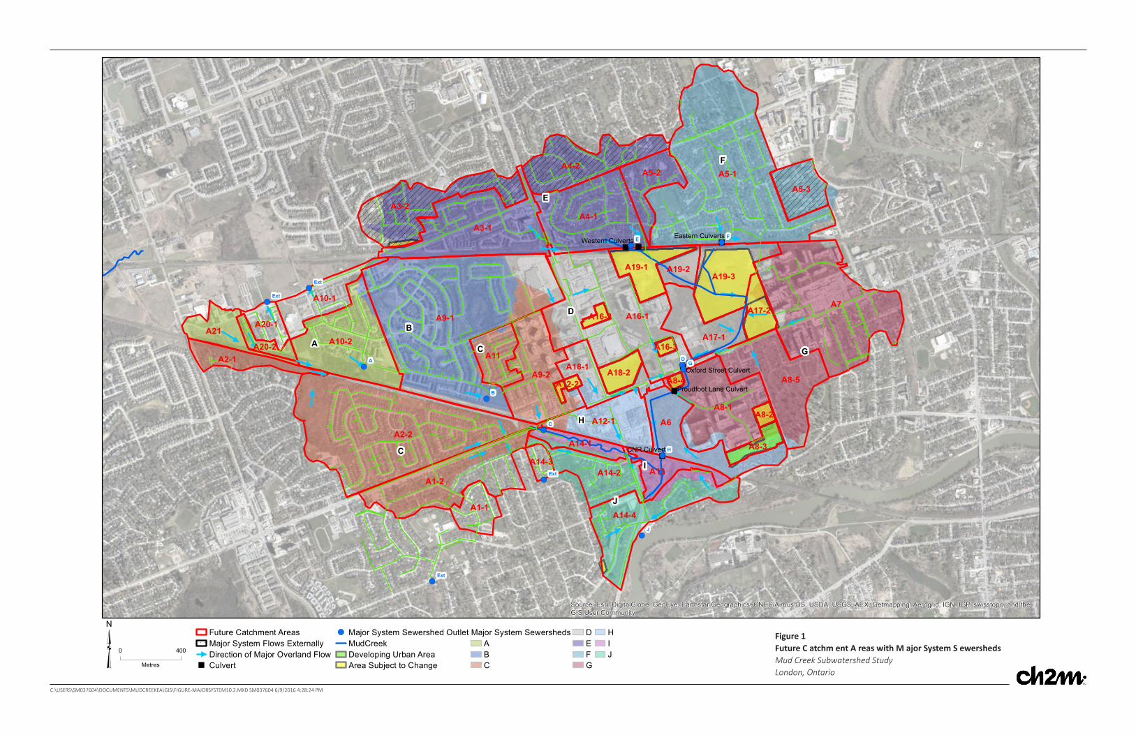
Catchment Delineation The subcatchments in the Mud Creek watershed were delineated using a 2007 digital elevation model (DEM) with a 5 m resolution. The delineation exercise was performed in ArcGIS. Figure 1 shows the catchment map along with typical overland (major) flow paths and piped (minor) system within the catchment. Typically, it is appropriate to consider the minimum amount of detail during catchment discretization, such as fewer subcatchments with large areas, meeting the objectives of the study. However, in anticipation of potential future application of the hydrologic model to investigate the impact of storm water management facilities including permanent private systems (PPS) for development parcels in the subwatershed, these potential future scenarios were considered in model development. Several future development parcels were identified within the subwatershed with potential for PPS. Development parcels were therefore defined as separate subcatchments.
In order to develop the model to assess both development impacts as well as flood hazard assessment, the subwatershed was, therefore, divided into a greater number of subcatchments than would generally be required for solely evaluating flood hazard. Delineated subcatchments were assumed to have uniform hydrological runoff characteristics in the model.
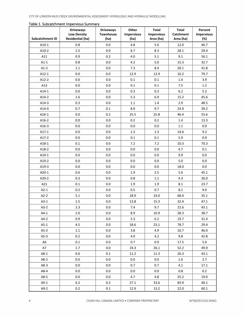
Imperviousness The percent imperviousness value for each model catchment was estimated through a GIS exercise. The UTRCA provided a GIS layer that included features such as buildings, roads, large parking lots, and sidewalks defined by polygons. The GIS layer did not include the low density residential driveways. The area for residential driveways was incorporated in the calculation of imperviousness by using a representative area of 79 m2 per unit as per a methodology developed by the UTRCA. This area was then multiplied by the total number of low density residential properties within a given subcatchment. The total area of buildings, roads, sidewalk, parking lots, and driveways within a given subcatchment was considered its impervious area. Percent imperviousness was calculated as the impervious area divided by total area of each catchment. The summary of impervious calculation is provided in Table 1 along with the final impervious values for each subcatchment.
"""
"
"
"
!(
!(
!(!(
!(
!(
!(
!(
!(
!(
!(
!(
!(
!(
A7A9-1
A5-1
A2-2
A16-1
A3-1
A6
A4-1
A1-2
A8-1
A8-5
A3-2
A10-2
A9-2
A14-4
A4-2
A19-3
A12-1
A14-2
A17-1
A11
A5-2
A21
A5-3
A10-1
A13
A18-1A2-1
A19-1
A1-1
A14-1
A17-2A20-1
A19-2
A18-2
A8-3
A20-2
A14-3
A8-2
A12-2
A16-2
A16-3
A8-4
D
E
F
G
C
B
J
H
A C
I
G
J
H
B
D
E F
A
C
Ext
Ext
Ext
Ext
CNR Culvert
Western CulvertsEastern Culverts
Oxford Street Culvert
Proudfoot Lane Culvert
Source: Esri, DigitalGlobe, GeoEye, Earthstar Geographics, CNES/Airbus DS, USDA, USGS, AEX, Getmapping, Aerogrid, IGN, IGP, swisstopo, and theGIS User Community
0 400
Metres³ Future Catchment AreasMajor System Flows ExternallyDirection of Major Overland Flow
" Culvert
!( Major System Sewershed OutletMudCreekDeveloping Urban AreaArea Subject to Change
Major System SewershedsABC
DEFG
HIJ
Figure 1Future C atchm ent A reas with M ajor System S ewershedsMud Creek Subwatershed StudyLondon, Ontario
C:\USERS\SM037604\DOCUMENTS\MUDCREEKEA\GIS\FIGURE-MAJORSYSTEM10.2.MXD SM037604 6/9/2016 4:28:24 PM
CITY OF LONDON MUD CREEK ENVIRONMENTAL ASSESSMENT HYDROLOGIC AND HYDRAULIC MODELLING
4 CH2M HILL CANADA LIMITED • COMPANY PROPRIETARY WT0629151011KWO
Table 1. Subcatchment Impervious Summary
Subcatchment ID
Driveways Low Density
Residential (ha)
Driveways Townhouse
(ha)
Other Impervious
(ha)
Total Impervious Area (ha)
Total Catchment Area (ha)
Percent Impervious
(%)
A10-1 0.8 0.0 4.8 5.6 12.0 46.7
A10-2 1.5 0.0 6.7 8.3 28.1 29.4
A11 0.9 0.2 4.0 5.1 9.1 56.1
A1-1 0.8 0.0 4.2 5.0 15.3 32.7
A1-2 1.1 0.0 7.3 8.4 20.1 41.8
A12-1 0.0 0.0 12.9 12.9 16.2 79.7
A12-2 0.0 0.0 0.1 0.1 1.4 3.9
A13 0.0 0.0 0.1 0.1 7.5 1.2
A14-1 0.0 0.0 0.3 0.3 6.2 5.2
A14-2 1.6 0.0 5.3 6.9 15.2 45.6
A14-3 0.3 0.0 1.1 1.4 2.9 48.5
A14-4 0.7 0.1 8.9 9.7 24.9 39.2
A16-1 0.0 0.2 25.5 25.8 46.4 55.6
A16-2 0.0 0.0 0.2 0.2 1.4 13.3
A16-3 0.0 0.0 0.0 0.0 1.1 0.0
A17-1 0.0 0.0 1.3 1.3 14.6 9.2
A17-2 0.0 0.0 0.1 0.1 5.9 0.9
A18-1 0.1 0.0 7.2 7.2 10.3 70.3
A18-2 0.0 0.0 0.0 0.0 4.7 0.1
A19-1 0.0 0.0 0.0 0.0 9.9 0.0
A19-2 0.0 0.0 0.0 0.0 5.0 0.0
A19-3 0.0 0.0 0.0 0.0 18.0 0.0
A20-1 0.6 0.0 1.9 2.5 5.6 45.1
A20-2 0.3 0.0 0.8 1.1 4.3 26.0
A21 0.1 0.0 1.9 1.9 8.1 23.7
A2-1 0.2 0.0 0.5 0.7 8.1 9.0
A2-2 5.1 0.0 18.9 24.0 68.4 35.1
A3-1 1.5 0.0 13.8 15.3 32.4 47.1
A3-2 2.3 0.0 7.4 9.7 22.6 43.1
A4-1 2.0 0.0 8.9 10.9 28.3 38.7
A4-2 0.9 0.0 5.3 6.2 19.7 31.4
A5-1 4.5 0.0 18.6 23.1 78.7 29.4
A5-2 1.1 0.0 3.8 4.9 10.7 46.0
A5-3 0.2 0.0 4.0 4.2 9.8 42.8
A6 0.1 0.0 0.7 0.9 17.5 5.0
A7 1.7 0.0 24.3 26.1 52.2 49.9
A8-1 0.0 0.1 11.2 11.3 26.3 43.1
A8-2 0.0 0.0 0.0 0.0 1.6 2.7
A8-3 0.0 0.0 0.7 0.7 4.1 17.1
A8-4 0.0 0.0 0.0 0.0 0.8 0.2
A8-5 0.0 0.0 4.7 4.8 25.2 19.0
A9-1 6.2 0.3 27.1 33.6 83.9 40.1
A9-2 0.2 0.1 12.9 13.2 22.0 60.1
CITY OF LONDON MUD CREEK ENVIRONMENTAL ASSESSMENT HYDROLOGIC AND HYDRAULIC MODELLING
WT0629151011KWO CH2M HILL CANADA LIMITED • COMPANY PROPRIETARY 5
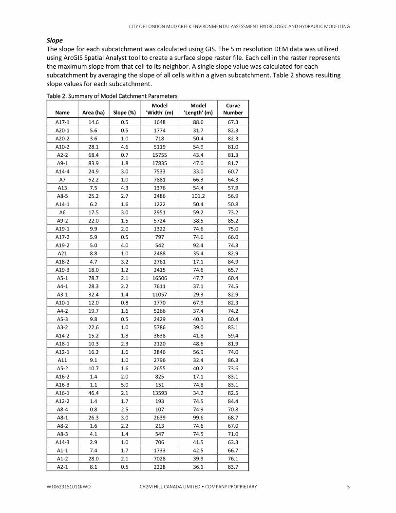
Slope The slope for each subcatchment was calculated using GIS. The 5 m resolution DEM data was utilized using ArcGIS Spatial Analyst tool to create a surface slope raster file. Each cell in the raster represents the maximum slope from that cell to its neighbor. A single slope value was calculated for each subcatchment by averaging the slope of all cells within a given subcatchment. Table 2 shows resulting slope values for each subcatchment.
Table 2. Summary of Model Catchment Parameters
Name Area (ha) Slope (%) Model
'Width' (m) Model
'Length' (m) Curve
Number
A17-1 14.6 0.5 1648 88.6 67.3 A20-1 5.6 0.5 1774 31.7 82.3 A20-2 3.6 1.0 718 50.4 82.3 A10-2 28.1 4.6 5119 54.9 81.0 A2-2 68.4 0.7 15755 43.4 81.3 A9-1 83.9 1.8 17835 47.0 81.7
A14-4 24.9 3.0 7533 33.0 60.7 A7 52.2 1.0 7881 66.3 64.3
A13 7.5 4.3 1376 54.4 57.9 A8-5 25.2 2.7 2486 101.2 56.9
A14-1 6.2 1.6 1222 50.4 50.8 A6 17.5 3.0 2951 59.2 73.2
A9-2 22.0 1.5 5724 38.5 85.2 A19-1 9.9 2.0 1322 74.6 75.0 A17-2 5.9 0.5 797 74.6 66.0 A19-2 5.0 4.0 542 92.4 74.3 A21 8.8 1.0 2488 35.4 82.9
A18-2 4.7 3.2 2761 17.1 84.9 A19-3 18.0 1.2 2415 74.6 65.7 A5-1 78.7 2.1 16506 47.7 60.4 A4-1 28.3 2.2 7611 37.1 74.5 A3-1 32.4 1.4 11057 29.3 82.9
A10-1 12.0 0.8 1770 67.9 82.3 A4-2 19.7 1.6 5266 37.4 74.2 A5-3 9.8 0.5 2429 40.3 60.4 A3-2 22.6 1.0 5786 39.0 83.1
A14-2 15.2 1.8 3638 41.8 59.4 A18-1 10.3 2.3 2120 48.6 81.9 A12-1 16.2 1.6 2846 56.9 74.0 A11 9.1 1.0 2796 32.4 86.3 A5-2 10.7 1.6 2655 40.2 73.6
A16-2 1.4 2.0 825 17.1 83.1 A16-3 1.1 5.0 151 74.8 83.1 A16-1 46.4 2.1 13593 34.2 82.5 A12-2 1.4 1.7 193 74.5 84.4 A8-4 0.8 2.5 107 74.9 70.8 A8-1 26.3 3.0 2639 99.6 68.7 A8-2 1.6 2.2 213 74.6 67.0 A8-3 4.1 1.4 547 74.5 71.0
A14-3 2.9 1.0 706 41.5 63.3 A1-1 7.4 1.7 1733 42.5 66.7 A1-2 28.0 2.1 7028 39.9 76.1 A2-1 8.1 0.5 2228 36.1 83.7
CITY OF LONDON MUD CREEK ENVIRONMENTAL ASSESSMENT HYDROLOGIC AND HYDRAULIC MODELLING
6 CH2M HILL CANADA LIMITED • COMPANY PROPRIETARY WT0629151011KWO
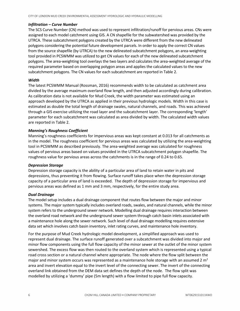
Infiltration – Curve Number The SCS Curve Number (CN) method was used to represent infiltration/runoff for pervious areas. CNs were assigned to each model catchment using GIS. A CN shapefile for the subwatershed was provided by the UTRCA. These subcatchment polygons created by the UTRCA were different from the new delineated polygons considering the potential future development parcels. In order to apply the correct CN values from the source shapefile (by UTRCA) to the new delineated subcatchment polygons, an area-weighting tool provided in PCSWMM was utilized to get CN values for each of the new delineated subcatchment polygons. The area-weighting tool overlays the two layers and calculates the area-weighted average of the required parameter based on overlapping polygon areas and applies the calculated values to the new subcatchment polygons. The CN values for each subcatchment are reported in Table 2.
Width The latest PCSWMM Manual (Rossman, 2016) recommends width to be calculated as catchment area divided by the average maximum overland flow length, and then adjusted accordingly during calibration. As calibration data is not available for Mud Creek, the width parameter was estimated using an approach developed by the UTRCA as applied in their previous hydrologic models. Width in this case is estimated as double the total length of drainage swales, natural channels, and roads. This was achieved through a GIS exercise utilizing the road layer and the subcatchment layer. The corresponding ‘length’ parameter for each subcatchment was calculated as area divided by width. The calculated width values are reported in Table 2.
Manning’s Roughness Coefficient Manning’s roughness coefficients for impervious areas was kept constant at 0.013 for all catchments as in the model. The roughness coefficient for pervious areas was calculated by utilizing the area-weighting tool in PCSWMM as described previously. The area-weighted average was calculated for roughness values of pervious areas based on values provided in the UTRCA subcatchment polygon shapefile. The roughness value for pervious areas across the catchments is in the range of 0.24 to 0.65.
Depression Storage Depression storage capacity is the ability of a particular area of land to retain water in pits and depressions, thus preventing it from flowing. Surface runoff takes place when the depression storage capacity of a particular area of land is exceeded. The depth of depression storage for impervious and pervious areas was defined as 1 mm and 3 mm, respectively, for the entire study area.
Dual Drainage The model setup includes a dual drainage component that routes flow between the major and minor systems. The major system typically includes overland roads, swales, and natural channels, while the minor system refers to the underground sewer network. Modelling dual drainage requires interaction between the overland road network and the underground sewer system through catch basin inlets associated with a maintenance hole along the sewer network. Such level of dual drainage modelling requires extensive data set which involves catch basin inventory, inlet rating curves, and maintenance hole inventory.
For the purpose of Mud Creek hydrologic model development, a simplified approach was used to represent dual drainage. The surface runoff generated over a subcatchment was divided into major and minor flow components using the full flow capacity of the minor sewer at the outlet of the minor system sewershed. The excess flow was then routed to the overland system which is represented using a typical road cross section or a natural channel where appropriate. The node where the flow split between the major and minor system occurs was represented as a maintenance hole storage with an assumed 2 m2 area and invert elevation equal to the invert level of the connecting sewer. The invert of the connecting overland link obtained from the DEM data set defines the depth of the node. The flow split was modelled by utilizing a ‘dummy’ pipe (5m length) with a flow limited to pipe full flow capacity.
CITY OF LONDON MUD CREEK ENVIRONMENTAL ASSESSMENT HYDROLOGIC AND HYDRAULIC MODELLING
WT0629151011KWO CH2M HILL CANADA LIMITED • COMPANY PROPRIETARY 7
Design Storms The model simulations were carried out using different design storm events based on ‘Short Duration Rainfall Intensity-Duration-Frequency (IDF) Data’ for the London Airport gauge based on precipitation record from 1943 to 2007. In addition, the UTRCA provided ‘Rain+Snowmelt Intensity, Duration, Frequency Values’ as published by the Canadian Climate Centre for the London Airport based on records from 1940 to 2002. The Rain+ Snowmelt IDF information was translated into a 10-day design storm following methodologies described in the ‘Reference Manual for the Use of Precipitation Design Events in the Upper Thames River Watershed (UTRCA, 2004).
A description of specific design rainfall events applied to each of the model scenarios is provided in the following section.
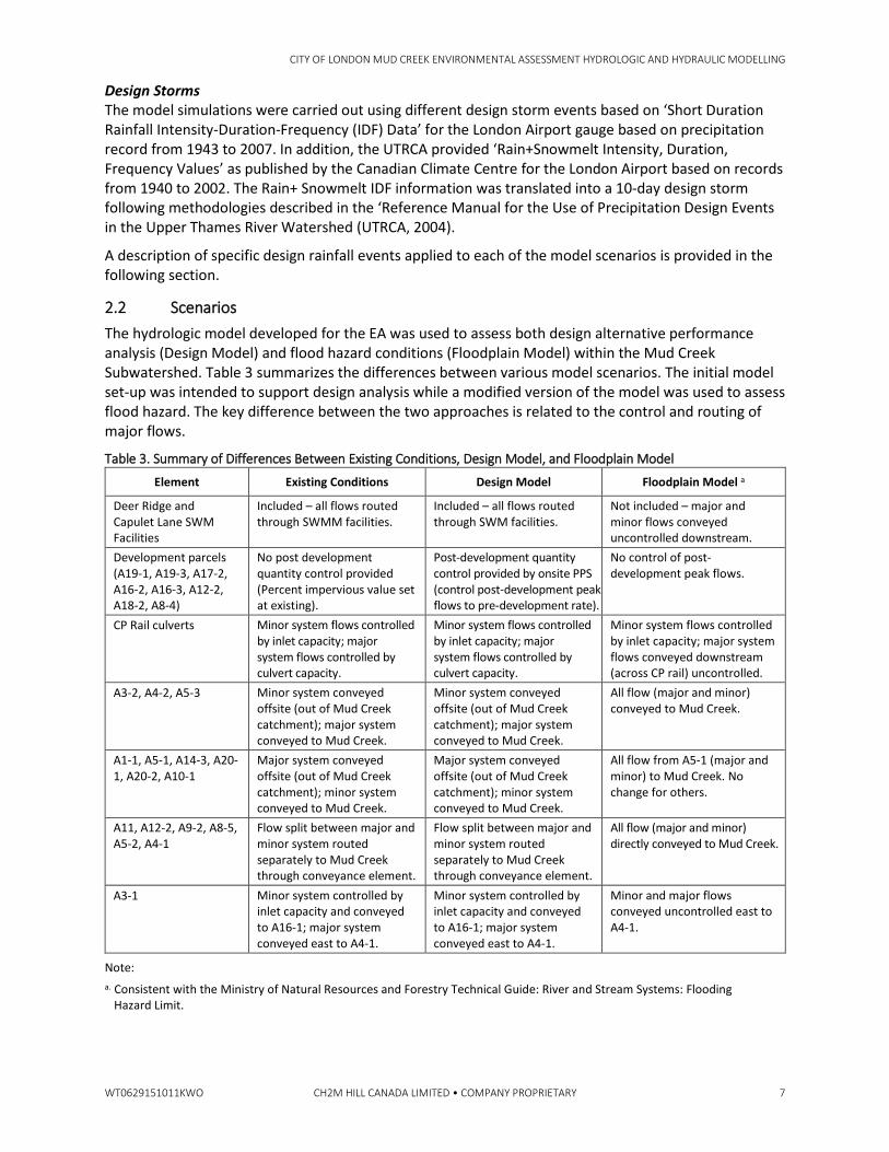
2.2 Scenarios The hydrologic model developed for the EA was used to assess both design alternative performance analysis (Design Model) and flood hazard conditions (Floodplain Model) within the Mud Creek Subwatershed. Table 3 summarizes the differences between various model scenarios. The initial model set-up was intended to support design analysis while a modified version of the model was used to assess flood hazard. The key difference between the two approaches is related to the control and routing of major flows.
Table 3. Summary of Differences Between Existing Conditions, Design Model, and Floodplain Model
Element Existing Conditions Design Model Floodplain Model a
Deer Ridge and Capulet Lane SWM Facilities
Included – all flows routed through SWMM facilities.
Included – all flows routed through SWM facilities.
Not included – major and minor flows conveyed uncontrolled downstream.
Development parcels (A19-1, A19-3, A17-2, A16-2, A16-3, A12-2, A18-2, A8-4)
No post development quantity control provided (Percent impervious value set at existing).
Post-development quantity control provided by onsite PPS (control post-development peak flows to pre-development rate).
No control of post-development peak flows.
CP Rail culverts Minor system flows controlled by inlet capacity; major system flows controlled by culvert capacity.
Minor system flows controlled by inlet capacity; major system flows controlled by culvert capacity.
Minor system flows controlled by inlet capacity; major system flows conveyed downstream (across CP rail) uncontrolled.
A3-2, A4-2, A5-3 Minor system conveyed offsite (out of Mud Creek catchment); major system conveyed to Mud Creek.
Minor system conveyed offsite (out of Mud Creek catchment); major system conveyed to Mud Creek.
All flow (major and minor) conveyed to Mud Creek.
A1-1, A5-1, A14-3, A20-1, A20-2, A10-1
Major system conveyed offsite (out of Mud Creek catchment); minor system conveyed to Mud Creek.
Major system conveyed offsite (out of Mud Creek catchment); minor system conveyed to Mud Creek.
All flow from A5-1 (major and minor) to Mud Creek. No change for others.
A11, A12-2, A9-2, A8-5, A5-2, A4-1
Flow split between major and minor system routed separately to Mud Creek through conveyance element.
Flow split between major and minor system routed separately to Mud Creek through conveyance element.
All flow (major and minor) directly conveyed to Mud Creek.
A3-1 Minor system controlled by inlet capacity and conveyed to A16-1; major system conveyed east to A4-1.
Minor system controlled by inlet capacity and conveyed to A16-1; major system conveyed east to A4-1.
Minor and major flows conveyed uncontrolled east to A4-1.
Note: a. Consistent with the Ministry of Natural Resources and Forestry Technical Guide: River and Stream Systems: Flooding
Hazard Limit.
CITY OF LONDON MUD CREEK ENVIRONMENTAL ASSESSMENT HYDROLOGIC AND HYDRAULIC MODELLING
8 CH2M HILL CANADA LIMITED • COMPANY PROPRIETARY WT0629151011KWO
2.2.1 Existing Conditions The existing conditions hydrologic model utilizes the existing infrastructure with the two storm water management facilities – Deer Ridge and Capulet Lane. The model takes into account the dual drainage between overland and minor system during routing of flow from subwatershed to Mud Creek. The existing conditions model does not consider the anticipated future storm water management ponds in the future development parcels, and utilizes the existing imperviousness value.
2.2.2 Future Conditions – Design Model This scenario applies future impervious values to the development parcels along with storage controls (PPS) to control post-development peak flow rates to the respective pre-development rate. The development parcels use the percent impervious values in the range of 70% to 90%. The dual drainage component is applied to model the flow split between major and minor systems for the subcatchments, which is similar to the existing conditions model as summarized in Table 3.
The preferred alternative as detailed in the EA report includes a lowered and enlarged CNR culvert, upgraded and relocated Oxford Street culvert, realignment of Mud Creek from Oxford Street to Proudfoot Lane, channel deepening/widening, and various naturalization, culvert cleaning, and enhancement elements. The proposed Mud Creek channel will have a compound configuration with the lower bankfull portion designed to contain flows from the 1:2-year rainfall event and the upper floodplain bench sized to convey flows from the 1:250-year event without overtopping.
For the design condition, the Chicago 3-hour design rainfall events (2-year and 250-year) were used to assess the conveyance capacity of the proposed system. A sensitivity analysis was also completed using the SCS-II 250-year 24-hour event to determine the critical event for sizing of the floodplain bench. Results of the modelling are discussed in Section 3.
Using this scenario, lateral inflows hydrographs from subwatersheds are obtained from the PCSWMM model for input to the hydraulic (HEC-RAS) model at corresponding discharge locations for unsteady flow modelling as described in Section 3.
2.2.3 Future Conditions – Floodplain Model This scenario applies future impervious values to the development parcels with no storage controls. The existing storm water management facilities are also bypassed and not included in the model. The flow split between major and minor is removed and all flows are routed uncontrolled to Mud Creek. The key differences between the floodplain scenario and future design scenario are summarized in Table 3. The future condition floodplain condition scenario is used to assess the impacts of the proposed alternative on flood hazard delineation along the main channel of Mud Creek.
For the floodplain condition, the Chicago 24-hour design rainfall event is used to derive peak flow estimates at key flow change locations in the main channel of Mud Creek as well as from tributaries for input to the hydraulic model as discussed in Section 3. Additionally, the 10-day snowmelt event is used to develop the boundary condition at the CNR culvert as also discussed in Section 3.
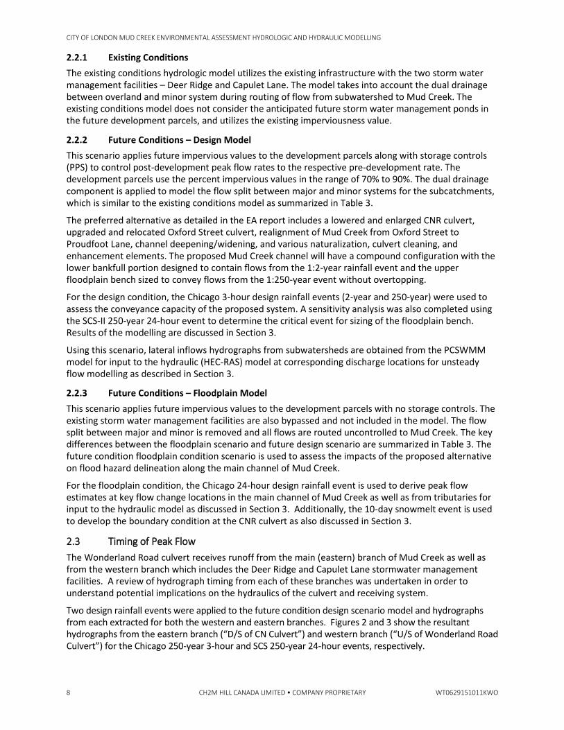
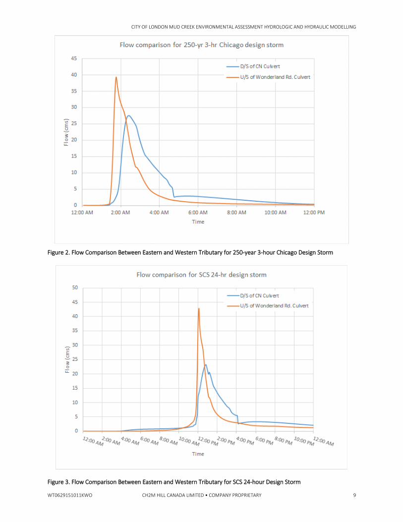
2.3 Timing of Peak Flow The Wonderland Road culvert receives runoff from the main (eastern) branch of Mud Creek as well as from the western branch which includes the Deer Ridge and Capulet Lane stormwater management facilities. A review of hydrograph timing from each of these branches was undertaken in order to understand potential implications on the hydraulics of the culvert and receiving system.
Two design rainfall events were applied to the future condition design scenario model and hydrographs from each extracted for both the western and eastern branches. Figures 2 and 3 show the resultant hydrographs from the eastern branch (“D/S of CN Culvert”) and western branch (“U/S of Wonderland Road Culvert”) for the Chicago 250-year 3-hour and SCS 250-year 24-hour events, respectively.
CITY OF LONDON MUD CREEK ENVIRONMENTAL ASSESSMENT HYDROLOGIC AND HYDRAULIC MODELLING
WT0629151011KWO CH2M HILL CANADA LIMITED • COMPANY PROPRIETARY 9
Figure 2. Flow Comparison Between Eastern and Western Tributary for 250-year 3-hour Chicago Design Storm
Figure 3. Flow Comparison Between Eastern and Western Tributary for SCS 24-hour Design Storm
CITY OF LONDON MUD CREEK ENVIRONMENTAL ASSESSMENT HYDROLOGIC AND HYDRAULIC MODELLING
10 CH2M HILL CANADA LIMITED • COMPANY PROPRIETARY WT0629151011KWO
For the Chicago 250-year 3-hour design event (Figure 2), the peak flow (27.6 m3/s) from the eastern branch (“D/S of CN Culvert”) occurred 39 minutes after the peak (39.9 m3/s) from western branch (“U/S of Wonderland Road Culvert”). Similarly, for the SCS 250-year 24-hour event (Figure 3), the peak flow from the eastern branch (23.2 m3/s) occurred 47 minutes after the peak (45.9 m3/s) of the western branch. It is, therefore, determined using the theoretical hydrologic model that peaks are not coincident from the eastern and western branches.
As discussed with the City and UTRCA, coincidental peaking of the tributaries at the Wonderland Road culvert has the potential to negatively impact the hydraulics of the Wonderland Road culvert and could increase the risk of flooding upstream of this culvert.. In the absence of flow/level monitoring data in this reach, assumptions of timing are related to model parametrization and theoretical conveyance in the existing hydrologic model.
It is therefore recommended that the City and UTRCA implement a flow/level monitoring program in the vicinity of the Wonderland Road culvert to collect data that can subsequently be used to calibrate the hydrologic model. Should flow monitoring data and additional related hydrologic model calibration suggest that peaks between the eastern and western branches are in fact more coincidental than predicted using the existing hydrologic model, additional measures can be considered such as reduced conveyance capacity at the CNR crossing. Monitoring and calibration is recommended to support further analysis and implementation of the detailed design.
3.0 Hydraulic Modelling Hydraulic modelling of the Mud Creek main channel was completed using the Army Corps of Engineers HEC-RAS v 4.1 model package, utilizing the HEC-GeoRAS module for ArcGIS environment to pre-process/develop and manage much of the input data. HEC-RAS was selected as it is freely available, updated on a regular basis, widely utilized in Ontario and North America for flood hazard evaluation, and interfaces directly with the ArcGIS environment through the HEC-GeoRAS module.
Three different HEC-RAS hydraulic models were used in this analysis:
1. Existing Condition: developed originally by the UTRCA for flood hazard mapping. This model was used as a starting point to develop the future condition models. This model was run under steady state condition.
2. Future Design Model Condition used to confirm that the proposed alternative as described in the EA was able to satisfy project EA objectives; model was run in unsteady state condition.
3. Future Floodplain Model Condition: used to establish the regulatory floodline for Mud Creek under the proposed condition as described in the EA. This model was run under steady state condition.
Details of model development, execution and results for each of the model scenarios are presented in the following sections.
3.1 Existing Conditions Model This model was developed originally by the UTRCA for flood hazard mapping. It contains all identified open channel in the Mud Creek subwatershed (i.e. Mud Creek main channel, west and east tributaries on the northeast end close to the Canadian Pacific Railway (CPR), West tributary close to the confluence of Mud Creek into the Thames River).
The elevations for the cross sections were derived by using a combination between a DEM and field survey data. Cross section elevation data outside of the defined channel area was derived from a DEM (25 cm cell size grid developed by the UTRCA in 2013). Within the defined channel area, the cross section elevation data was taken from field survey data.
Typical contraction/expansion coefficients were assigned at each cross-section as appropriate and as described in the HEC-RAS Hydraulic Reference Manual (contraction/expansion, bridge sections 0.3/0.5, other 0.1/0.3).
CITY OF LONDON MUD CREEK ENVIRONMENTAL ASSESSMENT HYDROLOGIC AND HYDRAULIC MODELLING
WT0629151011KWO CH2M HILL CANADA LIMITED • COMPANY PROPRIETARY 11
Manning’s roughness coefficients were assigned for the channel, and left and right overbank areas for each cross-section. These values were assigned through review of aerial photography and field observations made during field survey visits and comparison with descriptions provided in the HEC-RAS Hydraulic Reference.
Ineffective flow areas (areas that could contain water, but will likely not convey significant flow) were similarly established utilizing a combination of the aerial photography, topographic elevation information provided by the DEM, and existing flood hazard mapping. Seven structures were included in this model:
• One site-access culvert upstream of Oxford Street • Oxford Street culvert • One site-access culvert downstream of Oxford Street • Proudfoot Lane culvert • A pedestrian bridge upstream of the CNR Culvert • The CNR Culvert • The culvert under Wonderland Road and Riverside Drive, which outlets to the Thames River
3.2 Future Design Condition Model The existing conditions model was used as a base to develop the future condition hydraulic Design Model. This model represents the geometric characteristics of the Mud Creek for the preferred alternative (Alternative 4). This alternative consists of lowering and realigning the main channel of the Mud Creek following a linear trend from Oxford Street to the Wonderland Road and Riverside Drive Culvert. In addition, the Canadian National Railway (CNR) culvert was lowered by 2.7 m and enlarged from 1.7 m to 3.0 m in diameter. A number of CNR culvert configurations were assessed as part of the development of Alternative 4. The 3.0 diameter culvert concept optimized the flow through the culvert to reduce flooding upstream within the constraints associated with constructability and hydraulic grade line achievable. Finally, the bankfull channel was widened and deepened to contain the 1:2-year rainfall event. The bankfull channel sits in a floodplain bench that is generally three times the bankfull width and then is graded up to the surrounding ground level at a 3 horizontal to 1 vertical (3H:1V) slope.
The model extends from the headwaters down to the confluence of Mud Creek with the Thames River. Due to the complexity of the system, the model was developed using an unsteady approach to account for the interaction between culverts and the corresponding backwater effects and to assess the impact of various PCSWMM scenarios on the risk of flooding along Mud Creek. Also, the difference in time to peaks at the different subcatchments and how they contribute to floods at the creek is taken into account through this approach. Hydrographs at different locations were outfalls exist to the main channel were taken from the hydrologic (PCSWMM) model and incorporated into the HEC-RAS model as lateral hydrographs at the corresponding closest cross section.
The northwest tributary that discharges into Mud Creek between the CPR and Oxford Street was not included in this model. Instead, the lateral hydrographs associated with this tributary were added and combined in a single location at Mud Creek close to its confluence approximately 350 m downstream from the CPR crossing. A similar procedure was followed for the northeast tributary approximately 480 m downstream the CPR crossing.
As per discussions with the UTRCA, the interim Thames River 2-year water surface elevation (231.6 m) was used as the downstream boundary condition for the design condition model.
A Manning’s n roughness coefficient value of 0.035 was used for the channel bed through the design reach based on field observations and literature guidance. Roughness coefficients for the overbanks range from 0.065 to 0.08. In addition, a series of hydraulic components such as ineffective flow areas, blocked obstructions and levees were included in the model based on field survey data collected by the UTRCA.
CITY OF LONDON MUD CREEK ENVIRONMENTAL ASSESSMENT HYDROLOGIC AND HYDRAULIC MODELLING
12 CH2M HILL CANADA LIMITED • COMPANY PROPRIETARY WT0629151011KWO
Six structures were included in this model:
• One site-access culvert upstream of Oxford Street • Oxford Street culvert (enlarged and lowered) • Proudfoot Lane culvert • A pedestrian bridge upstream of the CNR Culvert • The CNR Culvert (enlarged and lowered) • The culvert under Wonderland Road and Riverside Drive, which outlets to the Thames River
3.3 Design Storm As discussed in Section 2, the Chicago 3-hour rainfall event was selected as the design event for the Future Design Model condition assessment. The 2-year event was used to assess the bankfull channel design while the 250-year event was used for assessing the channel design and adjacent floodplain bench design.
A sensitivity analysis was also completed using an SCS-II 250-year, 24-hour event and comparing results with the 3-hour Chicago event. Results of the sensitivity analysis are discussed in Section 3.5.1.
3.4 Floodplain Model The existing conditions model was used as a base for developing the future condition Floodplain Model. A modified version of the hydraulic Design Model presented in Section 3.2 was used to develop the Floodplain Model upstream of the CNR Culvert and is described in this section. The Floodplain Model also represents the geometric characteristics of the Mud Creek for the preferred alternative (Alternative 4).
The model was developed using a steady state approach since the interaction between culverts and time dependent inflow from the different subcatchments is not as important as the cumulative effect at key locations within the creek and tributaries. Peak flow at different locations where there is a significant change in flow were taken from the PCSWMM model and incorporated into the HEC-RAS model as “Flow Change Location” at the corresponding closest cross section. It is important to note that these are cumulative peak flows through the system and not lateral inflows as with the unsteady Design Model.
As with the design condition model, the interim Thames River 2-year water surface elevation (231.6 m) was used as the downstream boundary condition for the Floodplain Model. Similarly, Manning’s roughness coefficients used in the design condition model were also applied to the Floodplain Model.
Six structures were included in this model:
• One site-access culvert upstream of Oxford Street • Oxford Street culvert (enlarged and lowered) • Proudfoot Lane culvert • A pedestrian bridge upstream of the CNR Culvert • The CNR Culvert (enlarged and lowered) • The culvert under Wonderland Road and Riverside Drive, which outlets to the Thames River
The model extends from the headwaters down to the confluence of Mud Creek with the Thames River. The northwest tributary that discharges into Mud Creek between the CPR and Oxford Street was included in this model as a 680-m river reach that has its confluence into Mud Creek approximately 350 m downstream from the CPR crossing. The northeast tributary that discharges into Mud Creek between the CPR and Oxford Street was also included in this model as a 160-m river reach that has its confluence into Mud Creek approximately 480 m downstream from the CPR crossing.
From a review of initial HEC-RAS model results, it is evident that significant flooding is predicted upstream of the CNR rail embankment. The significant flooding is predicted due to the combination of an undersized culvert though the CNR rail embankment, and the lack of a proximate alternate flow
CITY OF LONDON MUD CREEK ENVIRONMENTAL ASSESSMENT HYDROLOGIC AND HYDRAULIC MODELLING
WT0629151011KWO CH2M HILL CANADA LIMITED • COMPANY PROPRIETARY 13
route (eg.overtop embankment, proximate alternate culvert or bridge opening through embankment). Instead, the potential alternate route for flood flows through the embankment is the Wonderland Road underpass, which has an approximate invert of 243 m (approximately 10 metres higher than the CNR culvert invert).
With the base HEC-RAS model set-up, the model utilizes the Wonderland Road underpass as the alternate flow route, and predicts a water elevation upstream of the CNR rail embankment of approximately 244 m. However, from a review of subwatershed topography, ponding of flood flows behind the CNN rail embankment would create potential alternate overland flow routes out of the subwatershed to the east through properties along Cherryhill Boulevard starting at elevations of approximately 239 m. Overland flow through the Cherryhill area would drain to the West London area along the Thames River near Oxford Street. Because of the lower elevations, it is expected that the overland flow routes to the east through the Cherryhill area would provide relief to potential ponding upstream of the CNR rail embankment prior to reaching the Wonderland Road underpass through the embankment. Hence, it could be considered that a flood hazard elevation of approximately 239 m upstream of the CNR rail embankment would be consistent with Provincial guidelines.
However, considering the relatively large volume of water required to fill the potential ponding area behind the CNR rail embankment prior to reaching an alternate flow route (as compared to the relatively small size of the drainage area to the CNR culvert), further investigation was appropriate to evaluate whether alternate flow routes were likely to be reached under regulatory flood conditions, and further, to investigate appropriate regulatory flood hazard elevations behind the CNR rail embankment. To evaluate, estimates were developed of the potential pond volume (stage-storage) behind the CNR rail embankment and CNR culvert discharge (stage-discharge), and then a critical design storm hydrograph were applied to estimate the maximum pond elevation under regulatory conditions. In this manner, flood attenuation from ponding on the upstream side of the CNR culvert would be considered for the purposes of investigating the flood hazard area on the upstream side of the CNR culvert. It should be noted that, although considering flood attenuation from ponding behind an undersized culvert is inconsistent with Provincial guidelines, there is precedent with this particular location as previous flood hazard studies for Mud Creek similarly considered such attenuation at the CNR embankment.
An additional model was developed to delineate the floodline upstream of the enlarged CNR Culvert. In essence it is the same steady model as described for downstream the CNR Culvert in terms of tributaries, cross sections, Manning’s roughness coefficients and flows. However, there are two differences between these models:
1. The steady model for upstream the CNR Culvert extends only from the headwaters up to the CNR Culvert.
2. The downstream boundary condition at the CNR Culvert is defined by the ponding water level produced by a snowmelt event for London extended over a period of 10 days.
This boundary condition was established using the PCSWMM model described in Section 2.2.3. However, the input data for the PCSWMM model was determined using the following steps:
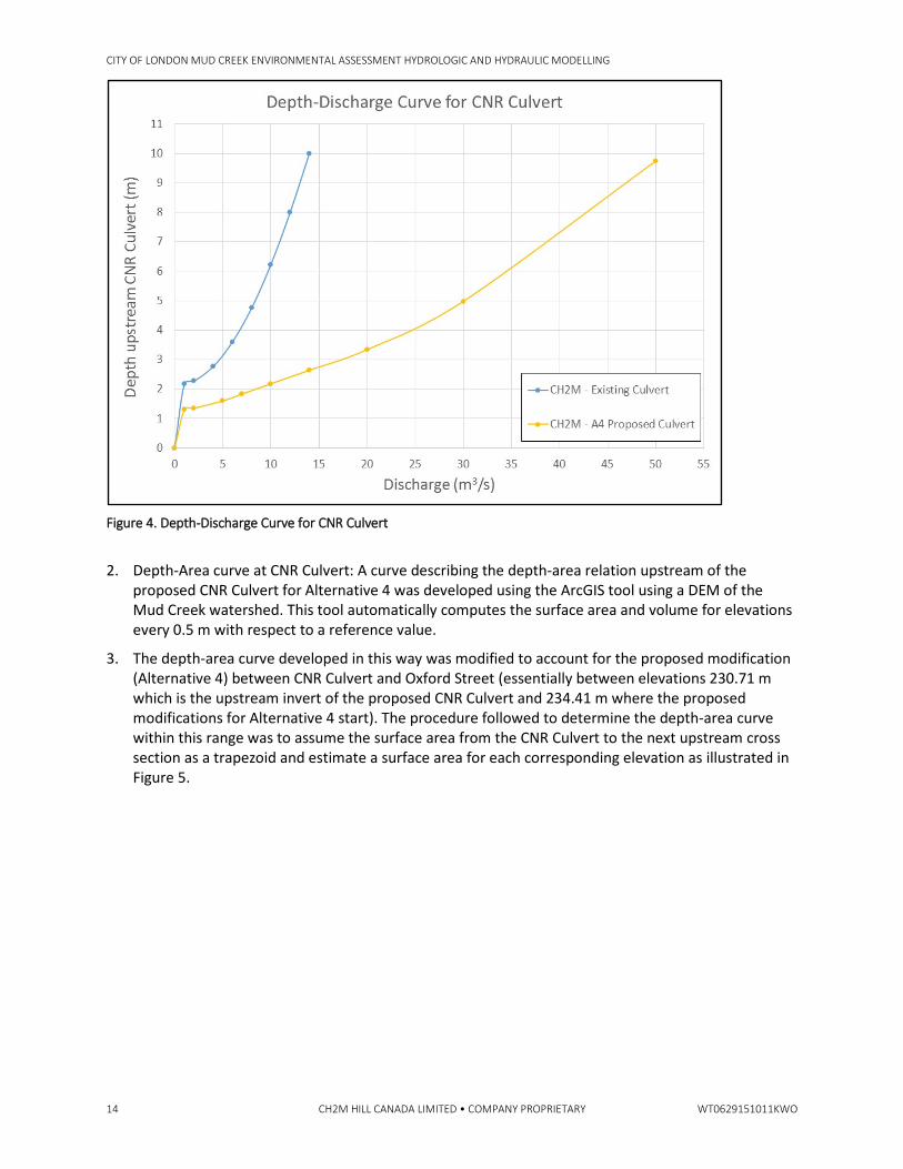
1. Depth-Discharge curve at CNR Culvert: A curve describing the depth-discharge relation at the proposed CNR Culvert for the preferred option (Alternative 4) was developed using the HEC-RAS model by computing the flow downstream the CNR Culvert given a particular water level upstream. This procedure was repeated several times by varying the water level upstream the CNR Culvert until enough points are obtained. The depth-discharge curve developed for the proposed CNR Culvert is shown in Figure 4. The figure also shows the curve associated with the proposed future condition with the lowered and enlarged CNR culvert.
CITY OF LONDON MUD CREEK ENVIRONMENTAL ASSESSMENT HYDROLOGIC AND HYDRAULIC MODELLING
14 CH2M HILL CANADA LIMITED • COMPANY PROPRIETARY WT0629151011KWO
Figure 4. Depth-Discharge Curve for CNR Culvert
2. Depth-Area curve at CNR Culvert: A curve describing the depth-area relation upstream of the proposed CNR Culvert for Alternative 4 was developed using the ArcGIS tool using a DEM of the Mud Creek watershed. This tool automatically computes the surface area and volume for elevations every 0.5 m with respect to a reference value.
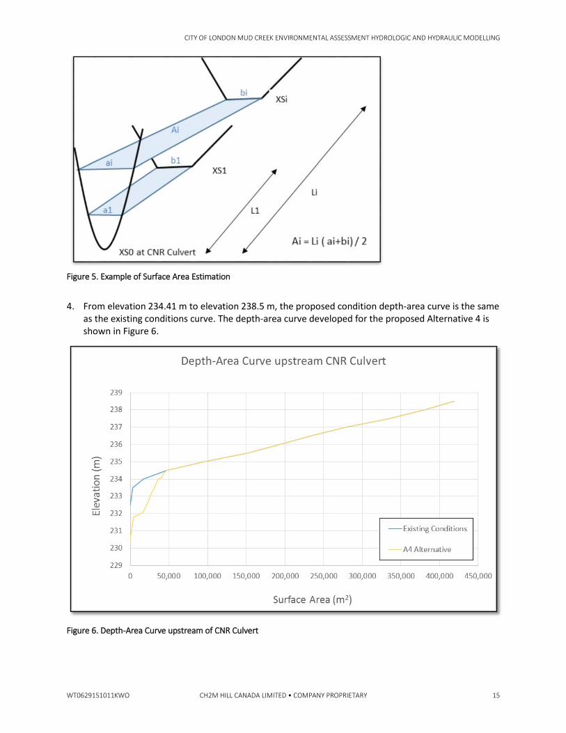
3. The depth-area curve developed in this way was modified to account for the proposed modification (Alternative 4) between CNR Culvert and Oxford Street (essentially between elevations 230.71 m which is the upstream invert of the proposed CNR Culvert and 234.41 m where the proposed modifications for Alternative 4 start). The procedure followed to determine the depth-area curve within this range was to assume the surface area from the CNR Culvert to the next upstream cross section as a trapezoid and estimate a surface area for each corresponding elevation as illustrated in Figure 5.
CITY OF LONDON MUD CREEK ENVIRONMENTAL ASSESSMENT HYDROLOGIC AND HYDRAULIC MODELLING
WT0629151011KWO CH2M HILL CANADA LIMITED • COMPANY PROPRIETARY 15
Figure 5. Example of Surface Area Estimation
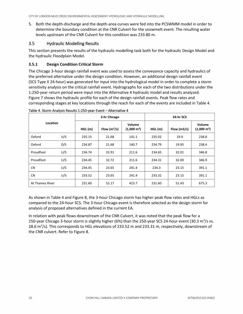
4. From elevation 234.41 m to elevation 238.5 m, the proposed condition depth-area curve is the same as the existing conditions curve. The depth-area curve developed for the proposed Alternative 4 is shown in Figure 6.
Figure 6. Depth-Area Curve upstream of CNR Culvert
CITY OF LONDON MUD CREEK ENVIRONMENTAL ASSESSMENT HYDROLOGIC AND HYDRAULIC MODELLING
16 CH2M HILL CANADA LIMITED • COMPANY PROPRIETARY WT0629151011KWO
5. Both the depth-discharge and the depth-area curves were fed into the PCSWMM model in order to determine the boundary condition at the CNR Culvert for the snowmelt event. The resulting water levels upstream of the CNR Culvert for this condition was 233.80 m.
3.5 Hydraulic Modelling Results This section presents the results of the hydraulic modelling task both for the hydraulic Design Model and the hydraulic Floodplain Model.
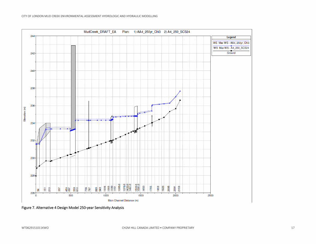
3.5.1 Design Condition Critical Storm The Chicago 3-hour design rainfall event was used to assess the conveyance capacity and hydraulics of the preferred alternative under the design condition. However, an additional design rainfall event (SCS Type II 24-hour) was generated for input into the hydrological model in order to complete a storm sensitivity analysis on the critical rainfall event. Hydrographs for each of the two distributions under the 1:250-year return period were input into the Alternative 4 hydraulic model and results analyzed. Figure 7 shows the hydraulic profile for each of the design rainfall events. Peak flow rates and corresponding stages at key locations through the reach for each of the events are included in Table 4.
Table 4. Storm Analysis Results 1:250-year Event – Alternative 4
Location
3-hr Chicago 24-hr SCS
HGL (m) Flow (m3/s) Volume
(1,000 m3) HGL (m) Flow (m3/s) Volume
(1,000 m3)
Oxford U/S 235.15 21.68 141.1 235.02 19.9 238.8
Oxford D/S 234.87 21.68 140.7 234.79 19.95 238.4
Proudfoot U/S 234.74 32.91 211.6 234.65 32.01 346.8
Proudfoot U/S 234.45 32.72 211.6 234.31 32.00 346.9
CN U/S 234.45 23.65 241.4 234.3 23.15 391.1
CN U/S 233.52 23.65 241.4 233.32 23.15 391.1
At Thames River 231.60 52.17 423.7 231.60 51.43 675.3
As shown in Table 4 and Figure 8, the 3-hour Chicago storm has higher peak flow rates and HGLs as compared to the 24-hour SCS. The 3-hour Chicago event is therefore selected as the design storm for analysis of proposed alternatives defined in the current EA.
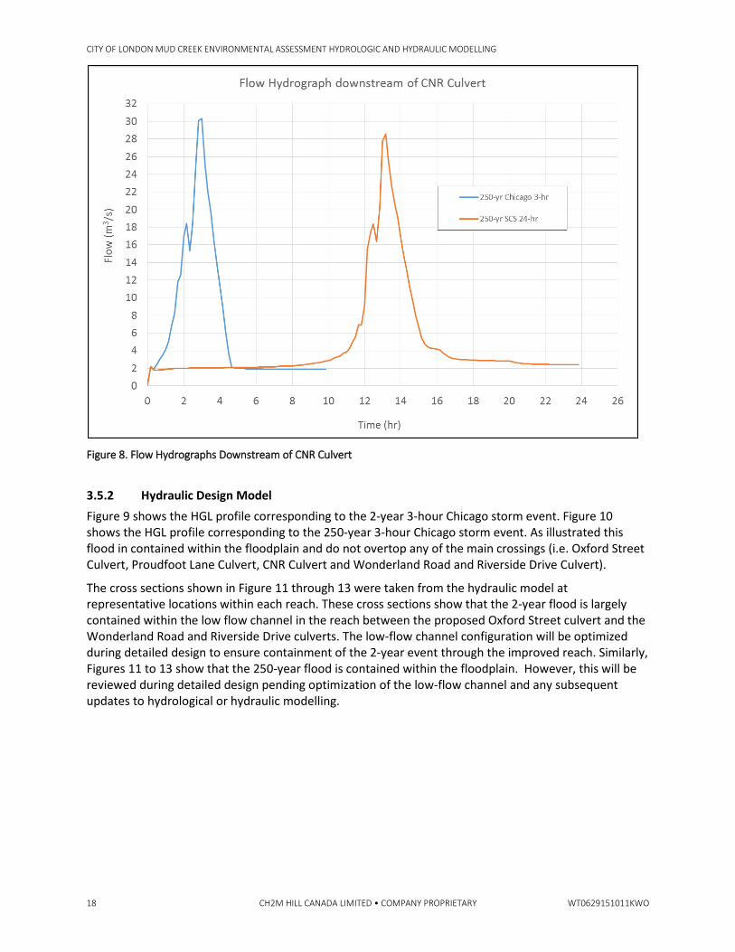
In relation with peak flows downstream of the CNR Culvert, it was noted that the peak flow for a 250-year Chicago 3-hour storm is slightly higher (6%) than the 250-year SCS 24-hour event (30.3 m3/s vs. 28.6 m3/s). This corresponds to HGL elevations of 233.52 m and 233.31 m, respectively, downstream of the CNR culvert. Refer to Figure 8.
CITY OF LONDON MUD CREEK ENVIRONMENTAL ASSESSMENT HYDROLOGIC AND HYDRAULIC MODELLING
WT0629151011KWO CH2M HILL CANADA LIMITED • COMPANY PROPRIETARY 17
Figure 7. Alternative 4 Design Model 250-year Sensitivity Analysis
CITY OF LONDON MUD CREEK ENVIRONMENTAL ASSESSMENT HYDROLOGIC AND HYDRAULIC MODELLING
18 CH2M HILL CANADA LIMITED • COMPANY PROPRIETARY WT0629151011KWO
Figure 8. Flow Hydrographs Downstream of CNR Culvert
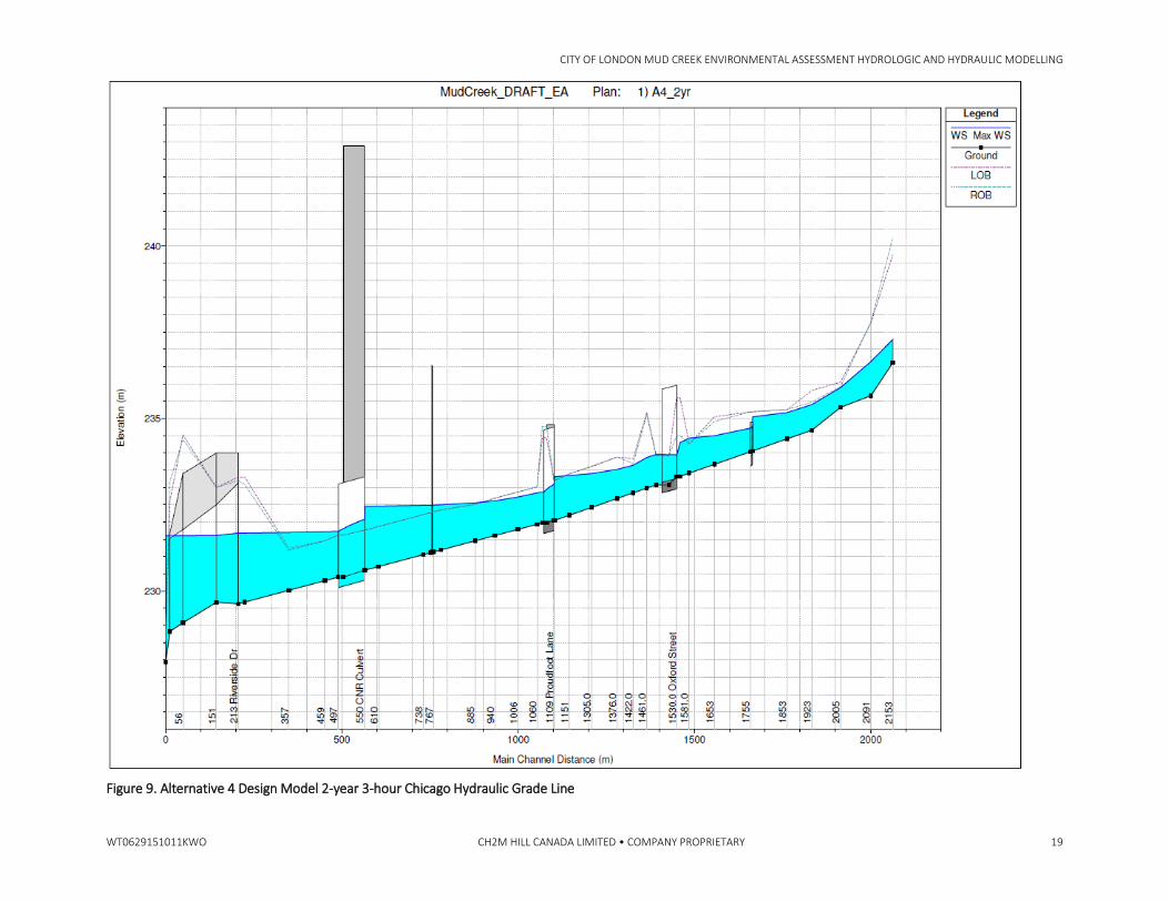
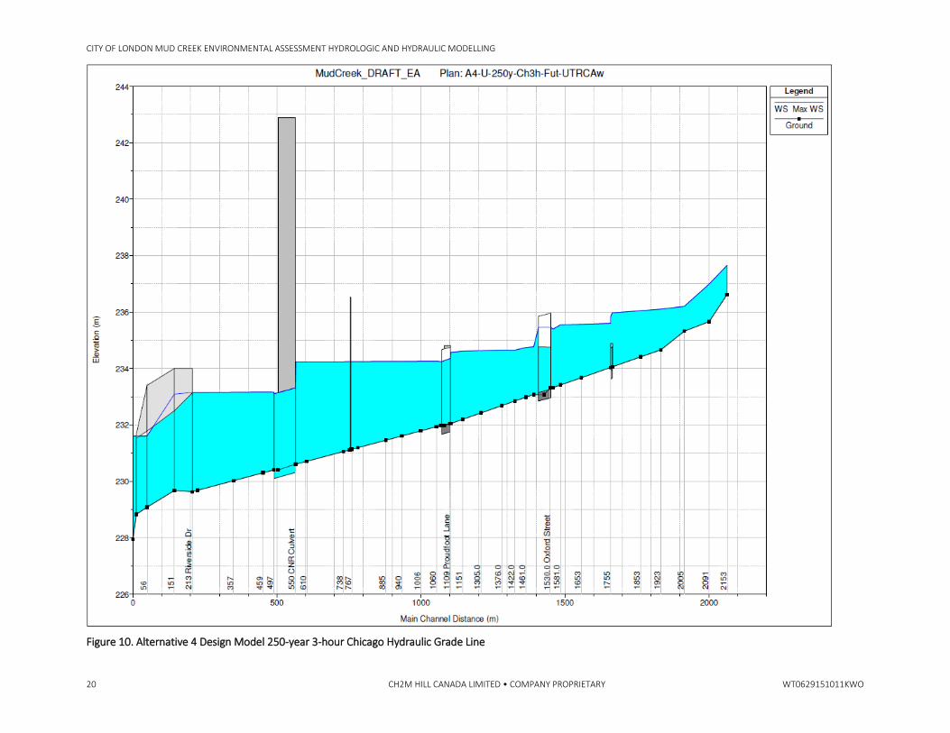
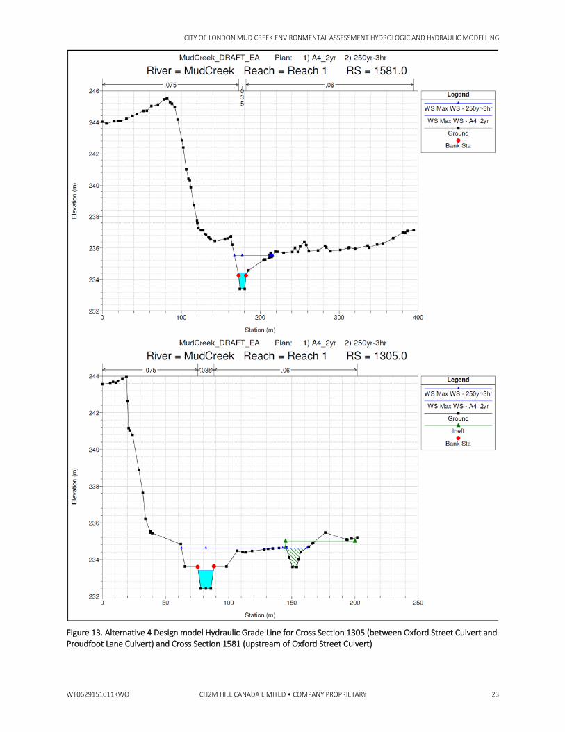
3.5.2 Hydraulic Design Model Figure 9 shows the HGL profile corresponding to the 2-year 3-hour Chicago storm event. Figure 10 shows the HGL profile corresponding to the 250-year 3-hour Chicago storm event. As illustrated this flood in contained within the floodplain and do not overtop any of the main crossings (i.e. Oxford Street Culvert, Proudfoot Lane Culvert, CNR Culvert and Wonderland Road and Riverside Drive Culvert).
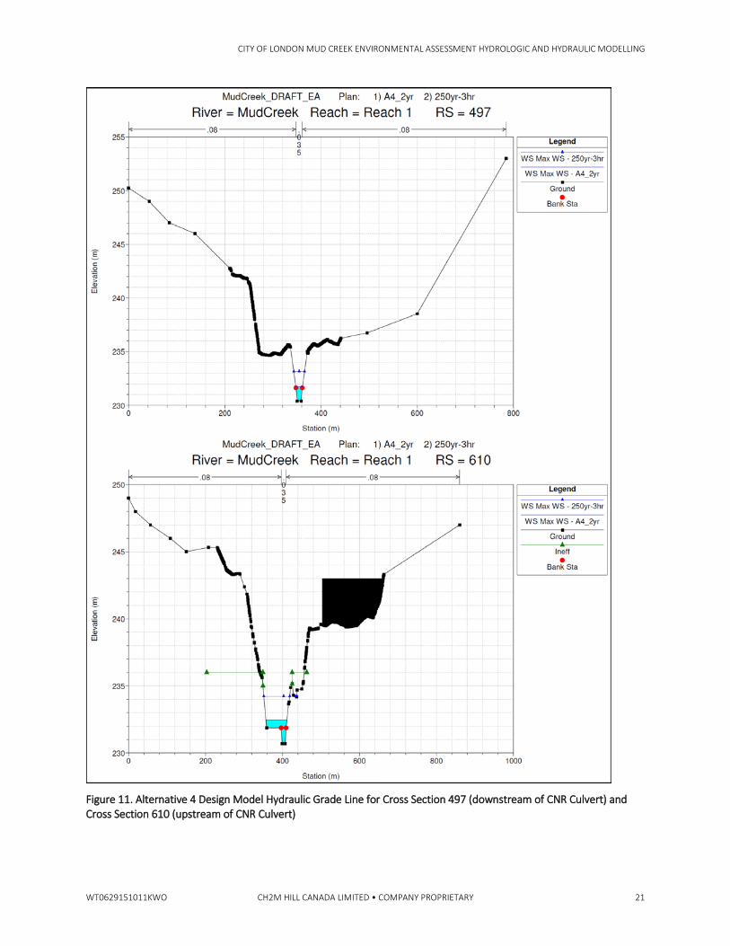
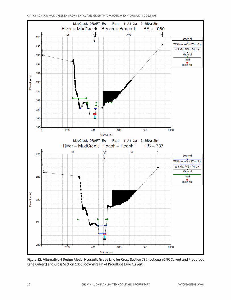
The cross sections shown in Figure 11 through 13 were taken from the hydraulic model at representative locations within each reach. These cross sections show that the 2-year flood is largely contained within the low flow channel in the reach between the proposed Oxford Street culvert and the Wonderland Road and Riverside Drive culverts. The low-flow channel configuration will be optimized during detailed design to ensure containment of the 2-year event through the improved reach. Similarly, Figures 11 to 13 show that the 250-year flood is contained within the floodplain. However, this will be reviewed during detailed design pending optimization of the low-flow channel and any subsequent updates to hydrological or hydraulic modelling.
CITY OF LONDON MUD CREEK ENVIRONMENTAL ASSESSMENT HYDROLOGIC AND HYDRAULIC MODELLING
WT0629151011KWO CH2M HILL CANADA LIMITED • COMPANY PROPRIETARY 19
Figure 9. Alternative 4 Design Model 2-year 3-hour Chicago Hydraulic Grade Line
CITY OF LONDON MUD CREEK ENVIRONMENTAL ASSESSMENT HYDROLOGIC AND HYDRAULIC MODELLING
20 CH2M HILL CANADA LIMITED • COMPANY PROPRIETARY WT0629151011KWO
Figure 10. Alternative 4 Design Model 250-year 3-hour Chicago Hydraulic Grade Line
CITY OF LONDON MUD CREEK ENVIRONMENTAL ASSESSMENT HYDROLOGIC AND HYDRAULIC MODELLING
WT0629151011KWO CH2M HILL CANADA LIMITED • COMPANY PROPRIETARY 21
Figure 11. Alternative 4 Design Model Hydraulic Grade Line for Cross Section 497 (downstream of CNR Culvert) and Cross Section 610 (upstream of CNR Culvert)
CITY OF LONDON MUD CREEK ENVIRONMENTAL ASSESSMENT HYDROLOGIC AND HYDRAULIC MODELLING
22 CH2M HILL CANADA LIMITED • COMPANY PROPRIETARY WT0629151011KWO
Figure 12. Alternative 4 Design Model Hydraulic Grade Line for Cross Section 787 (between CNR Culvert and Proudfoot Lane Culvert) and Cross Section 1060 (downstream of Proudfoot Lane Culvert)
CITY OF LONDON MUD CREEK ENVIRONMENTAL ASSESSMENT HYDROLOGIC AND HYDRAULIC MODELLING
WT0629151011KWO CH2M HILL CANADA LIMITED • COMPANY PROPRIETARY 23
Figure 13. Alternative 4 Design model Hydraulic Grade Line for Cross Section 1305 (between Oxford Street Culvert and Proudfoot Lane Culvert) and Cross Section 1581 (upstream of Oxford Street Culvert)
CITY OF LONDON MUD CREEK ENVIRONMENTAL ASSESSMENT HYDROLOGIC AND HYDRAULIC MODELLING
24 CH2M HILL CANADA LIMITED • COMPANY PROPRIETARY WT0629151011KWO
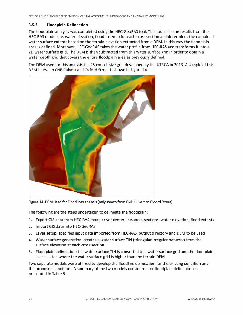
3.5.3 Floodplain Delineation The floodplain analysis was completed using the HEC-GeoRAS tool. This tool uses the results from the HEC-RAS model (i.e. water elevation, flood extents) for each cross section and determines the combined water surface extents based on the terrain elevation extracted from a DEM. In this way the floodplain area is defined. Moreover, HEC-GeoRAS takes the water profile from HEC-RAS and transforms it into a 2D water surface grid. The DEM is then subtracted from this water surface grid in order to obtain a water depth grid that covers the entire floodplain area as previously defined.
The DEM used for this analysis is a 25 cm cell size grid developed by the UTRCA in 2013. A sample of this DEM between CNR Culvert and Oxford Street is shown in Figure 14.
Figure 14. DEM Used for Floodlines analysis (only shown from CNR Culvert to Oxford Street) The following are the steps undertaken to delineate the floodplain:
1. Export GIS data from HEC-RAS model: river center line, cross sections, water elevation, flood extents 2. Import GIS data into HEC-GeoRAS 3. Layer setup: specifies input data imported from HEC-RAS, output directory and DEM to be used 4. Water surface generation: creates a water surface TIN (triangular irregular network) from the
surface elevation at each cross section 5. Floodplain delineation: the water surface TIN is converted to a water surface grid and the floodplain
is calculated where the water surface grid is higher than the terrain DEM Two separate models were utilized to develop the floodline delineation for the existing condition and the proposed condition. A summary of the two models considered for floodplain delineation is presented in Table 5.
CITY OF LONDON MUD CREEK ENVIRONMENTAL ASSESSMENT HYDROLOGIC AND HYDRAULIC MODELLING
WT0629151011KWO CH2M HILL CANADA LIMITED • COMPANY PROPRIETARY 25
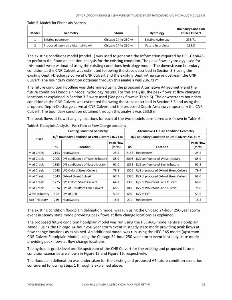
Table 5. Models for Floodplain Analysis
Model Geometry Storm Hydrology Boundary Condition
at CNR Culvert
1 Existing geometry Chicago 24-hr 250-yr Existing hydrology 236.71
2 Proposed geometry Alternative A4 Chicago 24-hr 250-yr Future hydrology 233.8
The existing conditions model (model 1) was used to generate the information required by HEC-GeoRAS to perform the flood delineation analysis for the existing condition. The peak flows hydrology used for this model were estimated using the existing conditions hydrology model. The downstream boundary condition at the CNR Culvert was estimated following the steps described in Section 3.3 using the existing Depth-Discharge curve at CNR Culvert and the existing Depth-Area curve upstream the CNR Culvert. The boundary condition obtained through this analysis was 236.71 m.
The future condition floodline was determined using the proposed Alternative A4 geometry and the future condition Floodplain Model hydrology results. For this analysis, the peak flows at flow changing locations as explained in Section 3.3 were used (See peak flows in Table 6). The downstream boundary condition at the CNR Culvert was estimated following the steps described in Section 3.3 and using the proposed Depth-Discharge curve at CNR Culvert and the proposed Depth-Area curve upstream the CNR Culvert. The boundary condition obtained through this analysis was 233.8 m.
The peak flows at flow changing locations for each of the two models considered are shown in Table 6.
Table 6. Floodplain Analysis – Peak Flow at Flow Change Locations
River
Existing Condition Geometry Alternative 4 Future Condition Geometry
D/S Boundary Condition at CNR Culvert 236.71 m D/S Boundary Condition at CNR Culvert 236.71 m
XS Location Peak Flow
(m3/s) XS Location Peak Flow
(m3/s)
Mud Creek 2153 Headwaters 25.5 2153 Headwaters 25.5
Mud Creek 2005 D/S confluence of West tributary 85.9 2005 D/S confluence of West tributary 85.9
Mud Creek 1853 D/S confluence of East tributary 91.0 1853 D/S confluence of East tributary 91.2
Mud Creek 1543 U/S Oxford Street Culvert 78.3 1555 U/S of proposed Oxford Street Culvert 79.4
Mud Creek 1343 Oxford Street Culvert 67.7 1376 D/S of proposed Oxford Street Culvert 68.0
Mud Creek 1275 D/S Oxford Street Culvert 64.2 1305 U/S of Proudfoot Lane Culvert 66.8
Mud Creek 1074 D/S of Proudfoot Lane Culvert 68.0 1060 D/S of Proudfoot Lane Culvert 71.0
West Tributary 692 D/S of CPR 53.6 692 D/S of CPR 53.6
East Tributary 219 Headwaters 18.5 219 Headwaters 18.5
The existing condition floodplain deliniation model was run using the Chicago 24-hour 250-year storm event in steady state mode providing peak flows at flow change locations as explained.
The proposed future condition floodplain model was run using the HEC-RAS model (entire Floodplain Model) using the Chicago 24-hour 250-year storm event in steady state mode providing peak flows at flow change locations as explained. An additional model was run using the HEC-RAS model (upstream CNR Culvert Floodplain Model) using the Chicago 24-hour 250-year storm event in steady state mode providing peak flows at flow change locations.
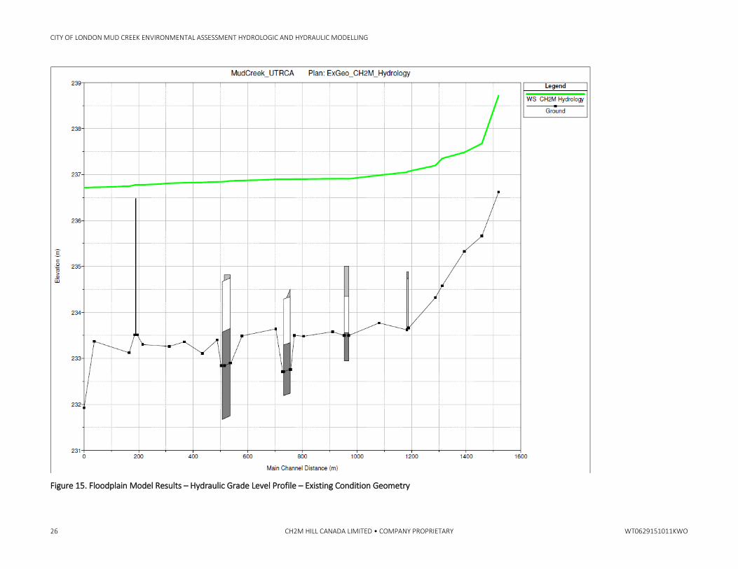
The hydraulic grade level profile upstream of the CNR Culvert for the existing and proposed future condition scenarios are shown in Figure 15 and Figure 16, respectively.
The floodplain delineation was undertaken for the existing and proposed A4 future condition scenarios considered following Steps 1 through 5 explained above.
CITY OF LONDON MUD CREEK ENVIRONMENTAL ASSESSMENT HYDROLOGIC AND HYDRAULIC MODELLING
26 CH2M HILL CANADA LIMITED • COMPANY PROPRIETARY WT0629151011KWO
Figure 15. Floodplain Model Results – Hydraulic Grade Level Profile – Existing Condition Geometry
CITY OF LONDON MUD CREEK ENVIRONMENTAL ASSESSMENT HYDROLOGIC AND HYDRAULIC MODELLING
WT0629151011KWO CH2M HILL CANADA LIMITED • COMPANY PROPRIETARY 27
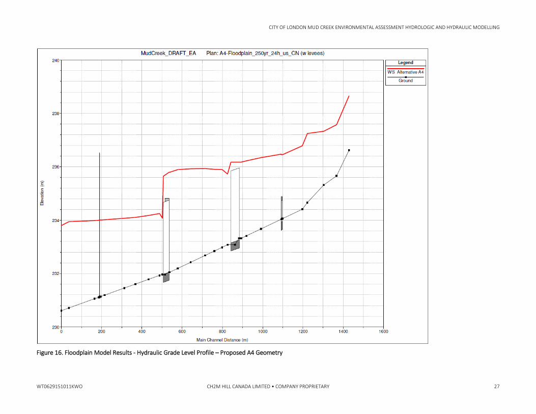
Figure 16. Floodplain Model Results - Hydraulic Grade Level Profile – Proposed A4 Geometry
CITY OF LONDON MUD CREEK ENVIRONMENTAL ASSESSMENT HYDROLOGIC AND HYDRAULIC MODELLING
28 CH2M HILL CANADA LIMITED • COMPANY PROPRIETARY WT0629151011KWO
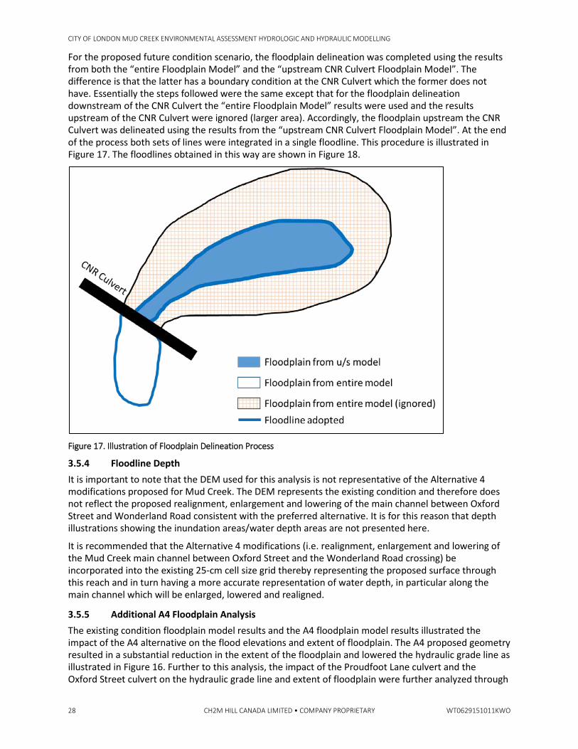
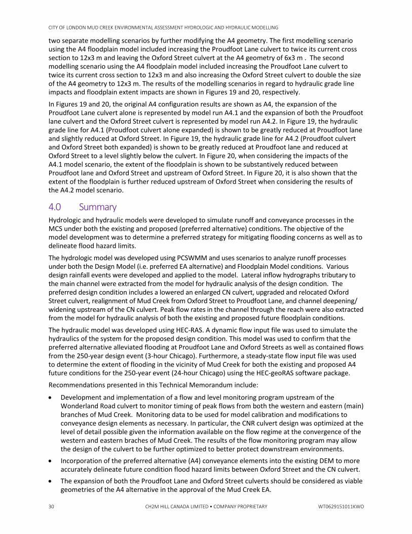
For the proposed future condition scenario, the floodplain delineation was completed using the results from both the “entire Floodplain Model” and the “upstream CNR Culvert Floodplain Model”. The difference is that the latter has a boundary condition at the CNR Culvert which the former does not have. Essentially the steps followed were the same except that for the floodplain delineation downstream of the CNR Culvert the “entire Floodplain Model” results were used and the results upstream of the CNR Culvert were ignored (larger area). Accordingly, the floodplain upstream the CNR Culvert was delineated using the results from the “upstream CNR Culvert Floodplain Model”. At the end of the process both sets of lines were integrated in a single floodline. This procedure is illustrated in Figure 17. The floodlines obtained in this way are shown in Figure 18.
Figure 17. Illustration of Floodplain Delineation Process
3.5.4 Floodline Depth It is important to note that the DEM used for this analysis is not representative of the Alternative 4 modifications proposed for Mud Creek. The DEM represents the existing condition and therefore does not reflect the proposed realignment, enlargement and lowering of the main channel between Oxford Street and Wonderland Road consistent with the preferred alternative. It is for this reason that depth illustrations showing the inundation areas/water depth areas are not presented here.
It is recommended that the Alternative 4 modifications (i.e. realignment, enlargement and lowering of the Mud Creek main channel between Oxford Street and the Wonderland Road crossing) be incorporated into the existing 25-cm cell size grid thereby representing the proposed surface through this reach and in turn having a more accurate representation of water depth, in particular along the main channel which will be enlarged, lowered and realigned.
3.5.5 Additional A4 Floodplain Analysis The existing condition floodplain model results and the A4 floodplain model results illustrated the impact of the A4 alternative on the flood elevations and extent of floodplain. The A4 proposed geometry resulted in a substantial reduction in the extent of the floodplain and lowered the hydraulic grade line as illustrated in Figure 16. Further to this analysis, the impact of the Proudfoot Lane culvert and the Oxford Street culvert on the hydraulic grade line and extent of floodplain were further analyzed through
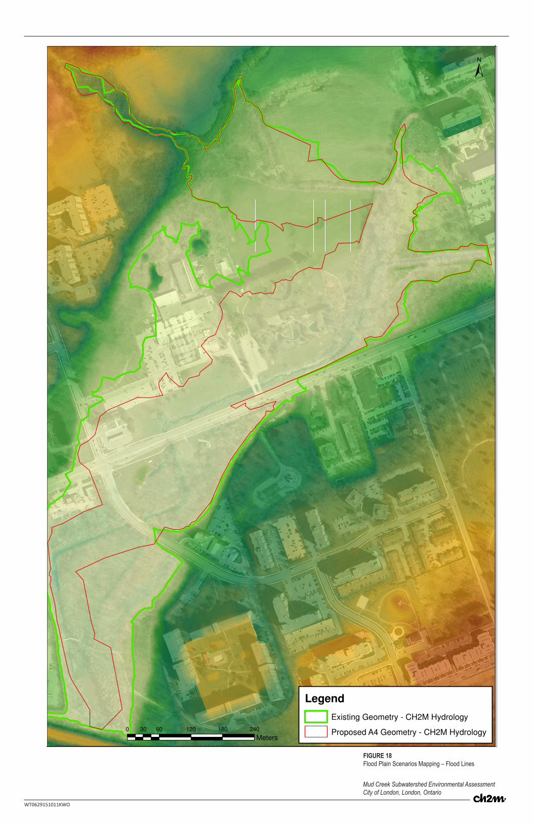
Mud Creek Subwatershed Environmental Assessment City of London, London, Ontario
WT0629151011KWO
FIGURE 18Flood Plain Scenarios Mapping – Flood Lines
0 60 120 180 24030
Meters
Legend
Existing Geometry - CH2M Hydrology
Proposed A4 Geometry - CH2M Hydrology
±
CITY OF LONDON MUD CREEK ENVIRONMENTAL ASSESSMENT HYDROLOGIC AND HYDRAULIC MODELLING
30 CH2M HILL CANADA LIMITED • COMPANY PROPRIETARY WT0629151011KWO
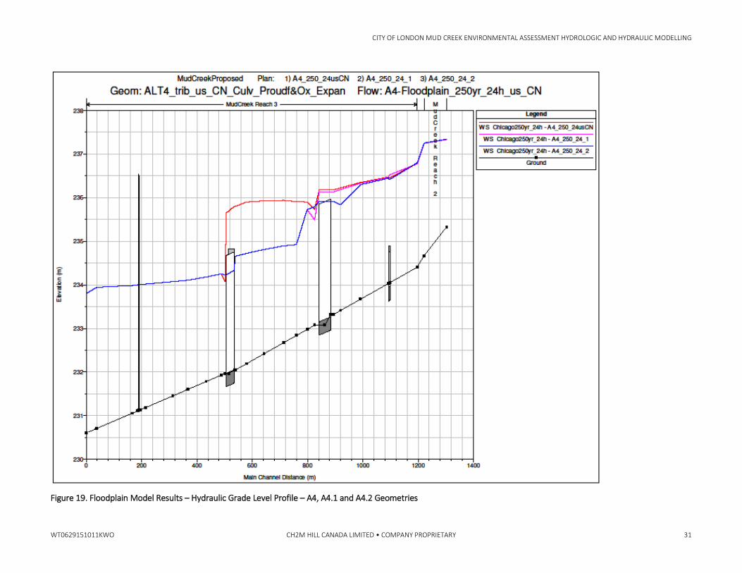
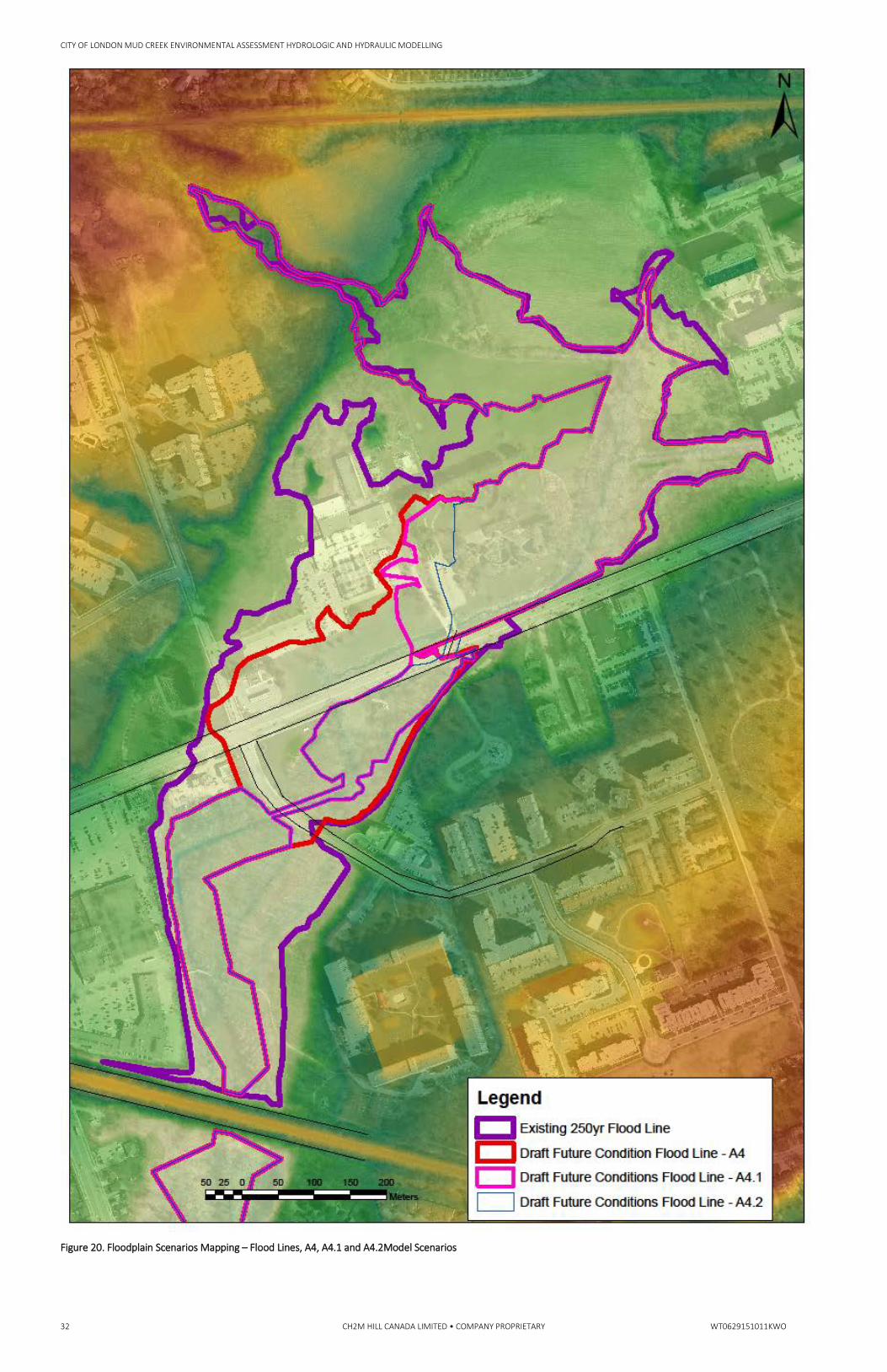
two separate modelling scenarios by further modifying the A4 geometry. The first modelling scenario using the A4 floodplain model included increasing the Proudfoot Lane culvert to twice its current cross section to 12x3 m and leaving the Oxford Street culvert at the A4 geometry of 6x3 m . The second modelling scenario using the A4 floodplain model included increasing the Proudfoot Lane culvert to twice its current cross section to 12x3 m and also increasing the Oxford Street culvert to double the size of the A4 geometry to 12x3 m. The results of the modelling scenarios in regard to hydraulic grade line impacts and floodplain extent impacts are shown in Figures 19 and 20, respectively.
In Figures 19 and 20, the original A4 configuration results are shown as A4, the expansion of the Proudfoot Lane culvert alone is represented by model run A4.1 and the expansion of both the Proudfoot lane culvert and the Oxford Street culvert is represented by model run A4.2. In Figure 19, the hydraulic grade line for A4.1 (Proudfoot culvert alone expanded) is shown to be greatly reduced at Proudfoot lane and slightly reduced at Oxford Street. In Figure 19, the hydraulic grade line for A4.2 (Proudfoot culvert and Oxford Street both expanded) is shown to be greatly reduced at Proudfoot lane and reduced at Oxford Street to a level slightly below the culvert. In Figure 20, when considering the impacts of the A4.1 model scenario, the extent of the floodplain is shown to be substantively reduced between Proudfoot lane and Oxford Street and upstream of Oxford Street. In Figure 20, it is also shown that the extent of the floodplain is further reduced upstream of Oxford Street when considering the results of the A4.2 model scenario.
4.0 Summary Hydrologic and hydraulic models were developed to simulate runoff and conveyance processes in the MCS under both the existing and proposed (preferred alternative) conditions. The objective of the model development was to determine a preferred strategy for mitigating flooding concerns as well as to delineate flood hazard limits.
The hydrologic model was developed using PCSWMM and uses scenarios to analyze runoff processes under both the Design Model (i.e. preferred EA alternative) and Floodplain Model conditions. Various design rainfall events were developed and applied to the model. Lateral inflow hydrographs tributary to the main channel were extracted from the model for hydraulic analysis of the design condition. The preferred design condition includes a lowered an enlarged CN culvert, upgraded and relocated Oxford Street culvert, realignment of Mud Creek from Oxford Street to Proudfoot Lane, and channel deepening/ widening upstream of the CN culvert. Peak flow rates in the channel through the reach were also extracted from the model for hydraulic analysis of both the existing and proposed future floodplain conditions.
The hydraulic model was developed using HEC-RAS. A dynamic flow input file was used to simulate the hydraulics of the system for the proposed design condition. This model was used to confirm that the preferred alternative alleviated flooding at Proudfoot Lane and Oxford Streets as well as contained flows from the 250-year design event (3-hour Chicago). Furthermore, a steady-state flow input file was used to determine the extent of flooding in the vicinity of Mud Creek for both the existing and proposed A4 future conditions for the 250-year event (24-hour Chicago) using the HEC-geoRAS software package.
Recommendations presented in this Technical Memorandum include:
• Development and implementation of a flow and level monitoring program upstream of the Wonderland Road culvert to monitor timing of peak flows from both the western and eastern (main) branches of Mud Creek. Monitoring data to be used for model calibration and modifications to conveyance design elements as necessary. In particular, the CNR culvert design was optimized at the level of detail possible given the information available on the flow regime at the convergence of the western and eastern braches of Mud Creek. The results of the flow monitoring program may allow the design of the culvert to be further optimized to better protect downstream environments.
• Incorporation of the preferred alternative (A4) conveyance elements into the existing DEM to more accurately delineate future condition flood hazard limits between Oxford Street and the CN culvert.
• The expansion of both the Proudfoot Lane and Oxford Street culverts should be considered as viable geometries of the A4 alternative in the approval of the Mud Creek EA.
CITY OF LONDON MUD CREEK ENVIRONMENTAL ASSESSMENT HYDROLOGIC AND HYDRAULIC MODELLING
WT0629151011KWO CH2M HILL CANADA LIMITED • COMPANY PROPRIETARY 31
Figure 19. Floodplain Model Results – Hydraulic Grade Level Profile – A4, A4.1 and A4.2 Geometries
CITY OF LONDON MUD CREEK ENVIRONMENTAL ASSESSMENT HYDROLOGIC AND HYDRAULIC MODELLING
32 CH2M HILL CANADA LIMITED • COMPANY PROPRIETARY WT0629151011KWO
Figure 20. Floodplain Scenarios Mapping – Flood Lines, A4, A4.1 and A4.2Model Scenarios