Embed Size (px)
Citation preview

APPENDIX E
Calcite Substation Detailed Project Description
Appendix E. Calcite Substation Detailed Project Description
Contents
1. Project Overview ..........................................................................................E-1
2. Station Light and Power for Stagecoach Facility......................................E-1
3. Project Location ...........................................................................................E-1
4. Calcite Substation ........................................................................................E-2 4.1 Substation Design and Equipment ................................................................ E-3 4.2 Grading and Land Disturbance...................................................................... E-3 4.3 Below Grade Construction............................................................................. E-4 4.4 Equipment Installation ................................................................................... E-5 4.5 Hazards and Hazardous Materials ................................................................ E-5 4.6 Waste Management ...................................................................................... E-5 4.6 Dust Control................................................................................................... E-5 4.8 Post-Construction Cleanup............................................................................ E-5 4.9 Operations and Maintenance......................................................................... E-5 4.10 Geotechnical Studies..................................................................................... E-6 4.11 Construction Equipment Personnel and Temporary Facilities ....................... E-6 4.12 Material & Equipment Staging Yard............................................................... E-9
5. Transmission Line (“T/L”) and Related Structures...................................E-9 5.1 E-220 kV Transmission Line Loop-In Design................................................. E-9
5.2 E-220 kV Generation Tie Line Extension Design......................................... E-10
5.3 Transmission Line Access and Spur Roads ................................................ E-11 5.4 Construction of New 220 kV Transmission Structures................................. E-11 5.5 Wire Stringing of 220 kV Conductor ............................................................ E-13 5.6 Land Disturbance ........................................................................................ E-14 5.7 Construction Site Cleanup ........................................................................... E-15 5.8 Operations and Maintenance....................................................................... E-15 5.9 Labor and Equipment .................................................................................. E-16
6. Distribution System for Station Light and Power ...................................E-20 6.1 Distribution for Calcite Substation................................................................ E-20 6.2 Construction Activities for Distribution Lines and Related Structures .......... E-20
7. Telecommunication Facilities ...................................................................E-24 7.1 Telecommunication Gen-tie Cables............................................................. E-25 7.2 Telecommunications Equipment.................................................................. E-25 7.3 Laydown Areas and Access Roads ............................................................. E-26 7.4 Construction Activities ................................................................................. E-26 7.5 Installation of Fiber Optic Cable on Poles.................................................... E-26 7.6 Installation of Fiber Optic Cable in Conduit.................................................. E-27
Stagecoach Solar Project Draft EIR i October 2021

Appendix E. Calcite Substation Detailed Project Description
7.7 Splicing Fiber Optic Cable ........................................................................... E-27 7.8 Operation and Maintenance ........................................................................ E-28
8. Alternative Calcite Substation ..................................................................E-32 8.1 Alternative Substation Property Location..................................................... E-32 8.2 E-220 kV Transmission Line Loop-in........................................................... E-32
8.3 Distribution System for Substation Light and Power.................................... E-37 8.4 Telecommunication Facilities....................................................................... E-41
Tables
Table SCE-1. Substation Ground Surface Improvement Materials and Estimated
Volumes ...................................................................................................................... E-4
Table SCE-2. Land Disturbance for Substation Construction...................................... E-4
Table SCE-3. Calcite Substation Project Construction, Equipment and Workforce Estimates by Activity: Construct 220 kV Substation and Access Road ...... E-6
Table SCE-4. Land Disturbance for Transmission Loop-in and SCE Portion of
Gen-tie Construction.................................................................................................. E-14
Table SCE-5. Calcite Substation Project Construction, Equipment and Workforce Estimates by Activity: Construct 220 kV Transmission Line Loop-in and Gen-tie................................................................................................................ E-17
Table SCE-6A. Distribution System Construction Activities, Construction Equipment and Workforce Estimates by Activity: Construct Distribution Line
Extension for Station Light & Power to Calcite Substation ........................................ E-21
Table SCE-7A. Telecommunication Systems Construction Activities, Construction Equipment and Workforce Estimates by Activity: Construct Barstow Repeater CS – Calcite Fiber Optic Cable .................................................................. E-28
Table SCE-7B. Telecommunication Systems Construction Activities, Construction Equipment and Workforce Estimates by Activity: Construct Calcite
Tap OPGW Slice at M29-T3...................................................................................... E-29
Table SCE-7C. Telecommunication Fiber Optic Cable Summary ............................. E-29
Table SCE-7D. Telecommunication Ground Disturbance Calculations ..................... E-30
Table SCE-7E. Telecommunication Systems Construction Activities, Construction Equipment and Workforce Estimates by Activity: PGW Gen-tie
Fiber Optic Cable....................................................................................................... E-30
Table SCE-7F. Telecommunication Systems Construction Activities, Construction Equipment and Workforce Estimates by Activity: Redundant Gen-tie Fiber Optic Cable ......................................................................................................................... E-31
Table SCE-7G. Telecommunication Fiber Optic Gen-tie Cable Summary ................ E-31
Table SCE-7H. Telecommunication Gen-tie Ground Disturbance Calculations ........ E-32
October 2021 ii Stagecoach Solar Project Draft EIR

Appendix E. Calcite Substation Detailed Project Description
Table SCE-8A. Land Disturbance for Transmission Loop-in and SCE Portion of
Gen-tie Construction.................................................................................................. E-33
Table SCE-8B. Calcite Substation Project Construction, Equipment and Workforce Estimates by Activity: Construct 220 kV Transmission Line Loop-in and Gen-tie................................................................................................................ E-34
Table SCE-9. Distribution System Construction Activities, Construction Equipment and Workforce Estimates by Activity: Construct Distribution Line
Extension for Station Light and Power....................................................................... E-38
Table SCE-10A. Telecommunication Systems Construction Activities, Construction Equipment and Workforce Estimates by Activity: Construct
Alternative Substation – Barstow Repeater CS Fiber Optic Cable ............................ E-41
Table SCE-10B. Telecommunication Systems Construction Activities, Construction Equipment and Workforce Estimates by Activity: Construct
Alternative Substation to OPGW splice at M29-T3 Fiber Optic Cable ....................... E-42
Table SCE-10C. Telecommunication Fiber Optic Cable Summary ........................... E-43
Table SCE-10D. Telecommunication Ground Disturbance Calculations ................... E-44
Attachment 1 Table A: Total Construction Water Demand: Proposed Substation Table B: Total Construction Water Demand: Alternative Substation
Figures Figure SCE-1. Proposed Calcite Substation
Figure SCE-2. Alternative Calcite Substation
Figure SCE-3. Proposed Transmission and Distribution Lines
Figure SCE-4. 220 kV Tubular Steel Pole Configuration
Figure SCE-5. Pole Configuration
Figure SCE-6. Pole and Crossarm Configuration with Raptor Guard
Figure SCE-7. Alternative Transmission and Distribution Lines
Stagecoach Solar Project Draft EIR iii October 2021

APPENDIX E
CALCITE SUBSTATION DETAILED PROJECT DESCRIPTION
1. PROJECT OVERVIEW
Southern California Edison Company (“SCE”) proposes to construct the Calcite Substation and associated facilities to interconnect the Aurora Solar, LLC 200 MW Stagecoach Solar
Project to SCE’s existing Lugo-Pisgah No. 1 220 kV Transmission Line (collectively, the
“Calcite Substation Project”). See Figure SCE-1, Proposed Calcite Substation. The following
is a summary of the Calcite Substation Project main components:
• Calcite Substation: Construct a 220 kV switchyard on approximately 7 acres along
with an approximately 4 acres for drainage, grading, and an access road.
• Transmission Lines: Loop-in the Lugo-Pisgah No. 1 220 kV Transmission Line into
Calcite Substation adding a total of approximately 5,000 feet of new transmission line
(two lines of approximately 2,500 feet located adjacent to one another) creating the
Calcite-Lugo and Calcite-Pisgah 220 kV Transmission Lines.
• Generation Tie Line Connection: Connect the Aurora Solar-built generation tie line
(“gen-tie”) into the SCE-owned Calcite Substation. SCE will construct up to three
structures and four spans, starting at the generator’s closest structure to the CalciteSubstation property to connect to the new position within the switchyard.
• Distribution Line for Calcite Substation Light and Power: Construct approxi
mately 700 feet of 12 kV overhead distribution line and approximately 3,100 feet of
underground distribution line (connecting the existing distribution system along Haynes
Road to Calcite Substation) to provide temporary power for construction and per
manent substation light and power.
• Telecommunications Facilities: Install fiber optic communication cables, equipment,
and associated structures for diverse path routing of communications required for the
Project.
2. STATION LIGHT AND POWER FOR STAGECOACH FACILITY
SCE will not be providing electric service to the Stagecoach Solar Project facilities.
3. PROJECT LOCATION
The proposed Calcite Substation would be located on an approximate 75--acre parcel of
land that extends on the west and east sides of California State Highway 247, directly north
of Haynes Road, in the County of San Bernardino (“Calcite Substation Property”). See Figure SCE-1, Proposed Calcite Substation. The proposed substation footprint would require
Stagecoach Solar Project Draft EIR E-1 October 2021

Appendix E. Calcite Substation Detailed Project Description
approximately 7 acres along with approximately 4 acres for drainage, grading, and an
access road, generally located within the western part of the approximate 75--acre parcel.
By looping the existing Lugo-Pisgah No.1 220 kV transmission line into Calcite Substation,
two new 220 kV transmission lines would be created. These transmission lines (T/Ls) would
depart from the existing Lugo-Pisgah No. 1 220 kV line approximately 2,500 feet south of
Calcite Substation, cross under SCE’s Eldorado-Lugo and Lugo-Mohave 500 kV lines and
enter Calcite Substation from the south.
The Stagecoach Solar Project’s portion of the 220 kV gen-tie line along with OPGW and
underground fiber are currently anticipated to extend onto an easement outside the Calcite
Substation Property, just west of the proposed Lugo-Pisgah No. 1 220 kV loop-in. Beginning
at the last structure to be constructed and owned by Aurora Solar (a dead-end structure)
just to the west of the Calcite Substation Property, SCE would construct all remaining
electrical facilities to extend the remainder of the gen-tie into the Substation.1 See Figure
SCE-3, Proposed Transmission and Distribution Lines.
The Calcite Substation would require the extension of the existing 12 kV distribution circuit
in order to provide temporary power and permanent substation light and power. The existing
12 kV overhead circuit would extend westward overhead on Haynes Road, for approximately
700 feet. The circuit would then continue underground for approximately 3,100 feet by
heading westward under the existing transmission right-of-way (ROW) along Haynes Road
and then north along the new Calcite Substation access road into the station light and power
rack within Calcite Substation. See Figure SCE-3, Proposed Transmission and Distribution
Lines.
The telecommunication facilities to support the Calcite Substation would require two new
fiber optic cables. The fiber optic cables would connect Calcite Substation to SCE’s Barstow
Repeater Communication Site (“CS”) and to a splice box on tower M29-T3 at SCE’s Lugo-
Mohave 500kV T/L. See Figure SCE1, Proposed Calcite Substation.
4. CALCITE SUBSTATION
The Calcite Substation would be a new regional 220 kV collector station initially needed to
support the Stagecoach Solar Project, measuring approximately 620 feet by 480 feet. The
Calcite Substation would be an unattended collector station (no power transformation)
surrounded by a wall, with a loop of top guard along the top, and with two gates.
1 The portion of the gen-tie running from the Stagecoach Solar Project to this last Aurora Solar structure is anticipated to be described elsewhere by Aurora Solar, not in this description of the work to be undertaken by SCE.
October 2021 E-2 Stagecoach Solar Project Draft EIR
Appendix E. Calcite Substation Detailed Project Description
4.1 SUBSTATION DESIGN AND EQUIPMENT
SCE would engineer, design, construct, and test the proposed Calcite Substation. The sub
station would be designed to accommodate a total of eight 220 kV positions, with four posi
tions initially constructed. Three positions would be utilized in the initial design: one position
for the Stagecoach Solar Project gen-tie line, one position for the Pisgah 220 kV transmis
sion line, and one position for the Lugo 220 kV transmission line. The remaining position
would be available for future network or generation tie-lines.
Calcite Substation would be initially equipped with:
• Two (2) overhead 220 kV buses
• Six (6) circuit breakers
• Twelve (12) group-operated disconnect switches
• One (1) Mechanical Electrical Equipment Room (MEER)
• Station light and power transformers and associated equipment
• Station lighting
• Permanent wall
• Perimeter Security Intrusion Detection System
4.2 GRADING AND LAND DISTURBANCE
The Calcite Substation Property would be prepared by clearing existing vegetation and
installing a temporary chain-link fence to surround the construction site. The Property would
be graded in accordance with approved grading plans. The area to be enclosed by the pro
posed substation perimeter wall would be graded to a slope that varies between one and
two percent. To protect the substation from flooding, and to keep the existing drainage
patterns, drainage conveyances would be constructed around the substation. These fea
tures would disturb an area approximately 35 feet wide around the substation (approximately
two acres) resulting in a total permanent disturbance area of approximately 11 acres. Final
site grading and drainage would be subject to the conditions of the grading permit obtained
from the County of San Bernardino (see Table SCE-1 below).
Additional temporary land disturbance (up to approximately 4 acres) within the proposed
Calcite Substation Property may be necessary for temporary equipment storage and mate
rial staging areas. An additional 3 acres would be temporarily disturbed due to construction
grading (see Table SCE-2 below).
The Calcite Substation access road would be 24 feet wide and composed of asphalt
concrete. This road would connect to Highway 247 (Barstow Road) and would require the
improvement of approximately 1,100 feet of the existing Haynes Road and the establishment
of approximately 800 feet of new road. Permanent land disturbance would be approximately
2 acres on the Calcite Substation Property. Any permits needed for the access road would
be acquired from the local agencies.
Stagecoach Solar Project E-3 October 2021
Appendix E. Calcite Substation Detailed Project Description
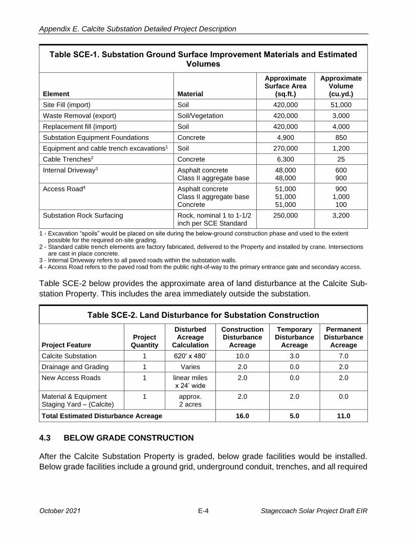
Table SCE-1. Substation Ground Surface Improvement Materials and Estimated Volumes
Element Material
Approximate Surface Area
(sq.ft.)
Approximate Volume (cu.yd.)
Site Fill (import) Soil 420,000 51,000
Waste Removal (export) Soil/Vegetation 420,000 3,000
Replacement fill (import) Soil 420,000 4,000
Substation Equipment Foundations Concrete 4,900 850
Equipment and cable trench excavations1 Soil 270,000 1,200
Cable Trenches2 Concrete 6,300 25
Internal Driveway3 Asphalt concrete Class II aggregate base
48,000 48,000
600 900
Access Road4 Asphalt concrete Class II aggregate base Concrete
51,000 51,000 51,000
900 1,000 100
Substation Rock Surfacing Rock, nominal 1 to 1-1/2 inch per SCE Standard
250,000 3,200
1 -
-
--
Excavation “spoils” would be placed on site during the below-ground construction phase and used to the extent possible for the required on-site grading.
2 Standard cable trench elements are factory fabricated, delivered to the Property and installed by crane. Intersections are cast in place concrete.
3 Internal Driveway refers to all paved roads within the substation walls. 4 Access Road refers to the paved road from the public right-of-way to the primary entrance gate and secondary access.
Table SCE-2 below provides the approximate area of land disturbance at the Calcite Sub
station Property. This includes the area immediately outside the substation.
Table SCE-2. Land Disturbance for Substation Construction
Project Feature Project
Quantity
Disturbed Acreage
Calculation
Construction Disturbance
Acreage
Temporary Disturbance
Acreage
Permanent Disturbance
Acreage
Calcite Substation 1 620' x 480’ 10.0 3.0 7.0
Drainage and Grading 1 Varies 2.0 0.0 2.0
New Access Roads 1 linear miles x 24’ wide
2.0 0.0 2.0
Material & Equipment Staging Yard – (Calcite)
1 approx. 2 acres
2.0 2.0 0.0
Total Estimated Disturbance Acreage 16.0 5.0 11.0
4.3 BELOW GRADE CONSTRUCTION
After the Calcite Substation Property is graded, below grade facilities would be installed.
Below grade facilities include a ground grid, underground conduit, trenches, and all required
October 2021 E-4 Stagecoach Solar Project Draft EIR
Appendix E. Calcite Substation Detailed Project Description
foundations. The design of the ground grid would be based on soil resistivity measurements
collected during a geotechnical investigation that would be conducted prior to construction.
4.4 EQUIPMENT INSTALLATION
Above grade installation of substation facilities (i.e., buses, circuit breakers, steel structures,
and the MEER) would commence after the below grade structures are in place. 0B
4.5 HAZARDS AND HAZARDOUS MATERIALS
Construction and operation of the Calcite Substation would require the limited use of hazard
ous materials such as fuels, lubricants, and cleaning solvents. SCE would comply with all
applicable laws relating to hazardous materials use, storage, and disposal. A Stormwater Pol
lution Prevention Plan (SWPPP) would also be prepared for the Calcite Substation Project.
4.6 WASTE MANAGEMENT
Construction of the Calcite Substation would result in the generation of various waste mate
rials including soil, vegetation, and sanitation waste (portable toilets). Soil excavated for the
Calcite Substation would either be used as fill or disposed of off-site at an appropriately
licensed waste facility. Sanitation waste (i.e., human generated waste) would be disposed
of according to sanitation waste management practices.
4.6 DUST CONTROL
During construction, water trucks from local water purveyors would be used to minimize the
quantity of airborne dust created by construction activities. Tables A and B in Attachment 1
present estimated construction water demand.
4.8 POST-CONSTRUCTION CLEANUP
Any damage to existing roads as a result of construction would be repaired once construc
tion is completed in accordance with local agency requirements. Following completion of
construction activities, SCE would also restore all areas that were temporarily disturbed by
construction of the Calcite Substation to as close to preconstruction conditions as possible
or where applicable to the conditions agreed upon between the landowner and SCE. In
addition, all construction materials and debris would be removed from the area and recycled
or properly disposed of off-site. SCE would conduct a final inspection to ensure that cleanup
activities were successfully completed.
4.9 OPERATIONS AND MAINTENANCE
The proposed Calcite Substation would be unstaffed, and electrical equipment within the
substation would be remotely monitored and controlled by an automated system from SCE’s
Stagecoach Solar Project E-5 October 2021

Appendix E. Calcite Substation Detailed Project Description
Lugo Substation Switching Center. SCE personnel would typically visit for electrical switch
ing and routine maintenance purposes. Routine maintenance would include equipment
testing, monitoring and repair.
4.10 GEOTECHNICAL STUDIES
Prior to the start of construction, SCE would conduct a geotechnical study of the Substation
Property and the transmission line routes that would include an evaluation of the depth to
the water table, evidence of faulting, liquefaction potential, physical properties of subsurface
soils, soil resistivity, and slope stability. Geotechnical borings would take place at various
depths throughout the Calcite Substation Property.
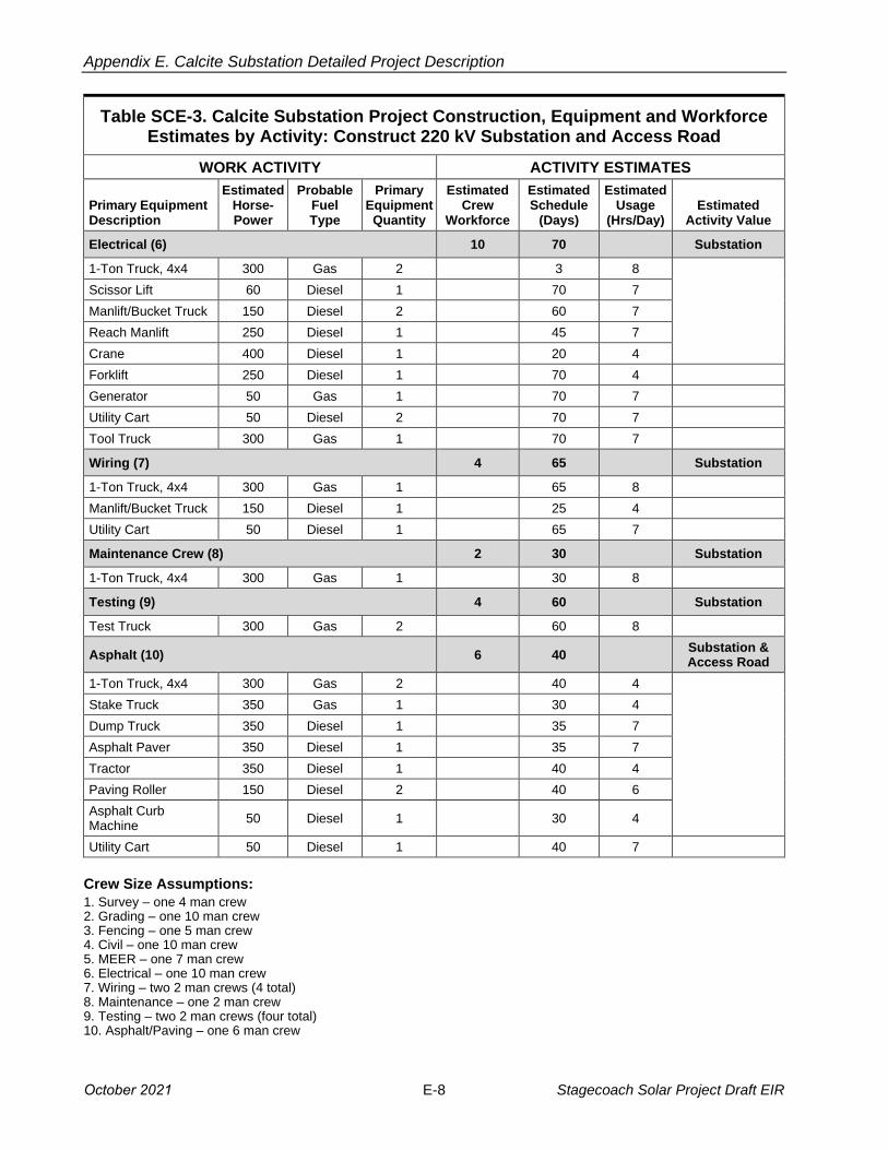
4.11 CONSTRUCTION EQUIPMENT PERSONNEL AND TEMPORARY FACILITIES
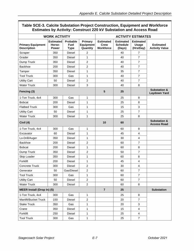
The estimated elements, materials, number of personnel and equipment required for con
struction of the Calcite Substation are summarized below in Table SCE-3. In addition to the
information provided in Table SCE-3, a temporary contractor office trailer and equipment
trailer would be placed within the proposed substation construction area during the construc
tion phase of the project.
Construction would be performed by either SCE construction crews or its contractors. Con
tractor construction personnel would be managed by SCE construction management per
sonnel. SCE anticipates a total of approximately 30 construction personnel working on any
given day. SCE anticipates that crews would work concurrently whenever possible; how
ever, the estimated deployment and number of crew members would be dependent upon
county permitting, material availability and construction scheduling. For example, installation
of electrical equipment (such as the MEER, wiring, and circuit breaker) installation may occur
while the transmission line construction proceeds.
Table SCE-3. Calcite Substation Project Construction, Equipment and Workforce Estimates by Activity: Construct 220 kV Substation and Access Road
WORK ACTIVITY ACTIVITY ESTIMATES
Primary Equipment Description
Estimated Horse-Power
Probable Fuel Type
Primary Equipment Quantity
Estimated Crew
Workforce
Estimated Schedule
(Days)
Estimated Usage
(Hrs/Day) Estimated
Activity Value
Survey (1) 4 10 Substation,
Laydown Yard & Access Road
1-Ton Truck, 4x4 300 Gas 2 10 8
Grading (2) 10 40 Substation,
Laydown Yard & Access Road
1-Ton Truck, 4x4 300 Gas 1 40 8
Dozer 350 Diesel 1 40 7
Loader 350 Diesel 2 40 7
October 2021 E-6 Stagecoach Solar Project Draft EIR
Appendix E. Calcite Substation Detailed Project Description
Table SCE-3. Calcite Substation Project Construction, Equipment and Workforce Estimates by Activity: Construct 220 kV Substation and Access Road
WORK ACTIVITY ACTIVITY ESTIMATES
Primary Equipment Description
Estimated Horse-Power
Probable Fuel Type
Primary Equipment Quantity
Estimated Crew
Workforce
Estimated Schedule
(Days)
Estimated Usage
(Hrs/Day) Estimated
Activity Value
Scraper 350 Diesel 2 40 7
Grader 350 Diesel 1 40 7
Dump Truck 350 Diesel 2 40 7
Backhoe 200 Diesel 2 40 7
Tamper 350 Diesel 1 35 7
Tool Truck 300 Gas 1 40 7
Utility Cart 50 Diesel 2 40 7
Water Truck 300 Diesel 3 40 8
Fencing (3) 5 25 Substation &
Laydown Yard
1-Ton Truck, 4x4 300 Gas 1 25 8
Bobcat 200 Diesel 1 25 8
Flatbed Truck 300 Gas 1 15 3
Utility Cart 50 Diesel 1 25 7
Water Truck 300 Diesel 1 25 8
Civil (4) 10 60 Substation & Access Road
1-Ton Truck, 4x4 300 Gas 1 60 8
Excavator 60 Diesel 1 45 4
Lo-Drill/Auger 350 Diesel 1 30 4
Backhoe 200 Diesel 2 60 7
Bobcat 200 Diesel 1 60 8
Dump Truck 350 Diesel 2 50 7
Skip Loader 350 Diesel 1 60 8
Forklift 200 Diesel 1 45 4
Concrete Truck 300 Diesel 2 30 4
Generator 50 Gas/Diesel 2 60 7
Tool Truck 300 Gas 1 60 7
Utility Cart 50 Diesel 2 60 7
Water Truck 300 Diesel 2 60 8
MEER Install (Drop In) (5) 7 25 Substation
1-Ton Truck, 4x4 300 Gas 1 25 8
Manlift/Bucket Truck 150 Diesel 2 20 7
Stake Truck 350 Gas 1 20 3
Crane 350 Diesel 1 15 4
Forklift 250 Diesel 1 25 4
Tool Truck 300 Gas 1 25 7
Stagecoach Solar Project E-7 October 2021
Appendix E. Calcite Substation Detailed Project Description
Table SCE-3. Calcite Substation Project Construction, Equipment and Workforce Estimates by Activity: Construct 220 kV Substation and Access Road
WORK ACTIVITY ACTIVITY ESTIMATES
Primary Equipment Description
Estimated Horse-Power
Probable Fuel Type
Primary Equipment Quantity
Estimated Crew
Workforce
Estimated Schedule
(Days)
Estimated Usage
(Hrs/Day) Estimated
Activity Value
Electrical (6) 10 70 Substation
1-Ton Truck, 4x4 300 Gas 2 3 8
Scissor Lift 60 Diesel 1 70 7
Manlift/Bucket Truck 150 Diesel 2 60 7
Reach Manlift 250 Diesel 1 45 7
Crane 400 Diesel 1 20 4
Forklift 250 Diesel 1 70 4
Generator 50 Gas 1 70 7
Utility Cart 50 Diesel 2 70 7
Tool Truck 300 Gas 1 70 7
Wiring (7) 4 65 Substation
1-Ton Truck, 4x4 300 Gas 1 65 8
Manlift/Bucket Truck 150 Diesel 1 25 4
Utility Cart 50 Diesel 1 65 7
Maintenance Crew (8) 2 30 Substation
1-Ton Truck, 4x4 300 Gas 1 30 8
Testing (9) 4 60 Substation
Test Truck 300 Gas 2 60 8
Asphalt (10) 6 40 Substation & Access Road
1-Ton Truck, 4x4 300 Gas 2 40 4
Stake Truck 350 Gas 1 30 4
Dump Truck 350 Diesel 1 35 7
Asphalt Paver 350 Diesel 1 35 7
Tractor 350 Diesel 1 40 4
Paving Roller 150 Diesel 2 40 6
Asphalt Curb Machine
50 Diesel 1 30 4
Utility Cart 50 Diesel 1 40 7
Crew Size Assumptions:
1. Survey – one 4 man crew2. Grading – one 10 man crew3. Fencing – one 5 man crew4. Civil – one 10 man crew5. MEER – one 7 man crew6. Electrical – one 10 man crew7. Wiring – two 2 man crews (4 total)8. Maintenance – one 2 man crew9. Testing – two 2 man crews (four total)10. Asphalt/Paving – one 6 man crew
October 2021 E-8 Stagecoach Solar Project Draft EIR

Appendix E. Calcite Substation Detailed Project Description
4.12 MATERIAL & EQUIPMENT STAGING YARD
Construction of the substation, transmission lines, distribution lines, and telecommunication
lines would require the establishment of approximately 4 acres of staging yards within the
Calcite Substation Property. This staging yard would be used as a reporting location for
workers, vehicle and equipment parking, and material storage.2 The yard may also have
construction trailers for supervisory and clerical personnel. The staging yard may be lit for
staging and security. Normal maintenance and refueling of construction equipment would
also be conducted at the yard. All refueling and storage of fuels would be in accordance with
the Storm Water Pollution Prevention Plan (SWPPP).
Preparation of the staging yard would include temporary perimeter fencing and depending
on existing ground conditions at the Property, possible minor grading to level the site, and
application of gravel or crushed rock for dust/erosion control.
The majority of the materials associated with construction efforts would be delivered by truck
to the staging yard, although some materials may be delivered directly to the temporary
construction laydown/work areas.
Any land that may be disturbed at the staging yard could be restored to preconstruction
conditions if there is no longer a need for the staging yard.
5. TRANSMISSION LINE (“T/L”) AND RELATED STRUCTURES
SCE’s transmission line requirements for the Stagecoach Solar Project interconnection to Calcite Substation and the Lugo-Pisgah No. 1 220 kV Transmission Line connection to
Calcite Substation are defined by the following components: loop-in lines, and gen-tie line
connection. Each of these components is described below.
5.1 E-220 KV TRANSMISSION LINE LOOP-IN DESIGN
The proposed Calcite Substation would connect to the Lugo-Pisgah No. 1 220 kV Transmis
sion Line via a loop-in T/L. The loop-in would modify the Lugo-Pisgah No. 1 220 kV Trans
mission Line creating two new line segments: the Calcite-Lugo 220 kV T/L and the Calcite-
Pisgah 220 kV T/L. Each new T/L segment entering into the Calcite Substation would be
2 Transmission line construction materials commonly stored at construction staging yards typically include, but may not be limited to: construction trailers; construction equipment; portable sanitation facilities; steel bundles; steel/wood poles; conductor reels; overhead ground wire (OHGW); hardware; insulators; cross arms; signage; consumables (such as fuel and filler compound); waste materials for salvaging, recycling, or disposal; and BMP materials (such as straw wattles, gravel, and silt fences). Substation construction materials commonly stored at the construction staging area include, but may not be limited to: portable construction trailers; sanitation facilities; electrical and construction equipment such as circuit breakers, disconnect switches, lightning arresters, transformers, vacuum switches, steel beams, rebar, foundation cages, conduit, insulators, conductor and cable reels, pull boxes and line hardware; and BMP materials (such as straw wattles, gravel, and silt fences).
Stagecoach Solar Project E-9 October 2021

Appendix E. Calcite Substation Detailed Project Description
approximately 2,500 feet long. See Figure SCE-3, Proposed Transmission and Distribution
Lines.
The proposed routes for these new T/Ls would require crossing under SCE’s Eldorado-Lugo
and Lugo-Mohave 500 kV lines. Crossing under the 500 kV lines would require direct embed
ding the static wire at each crossing for adequate grounding and to satisfy GO95 overhead
clearance requirements between circuits. See Figure SCE-4, 220 kV Tubular Steel Pole
Configuration.
The new 220 kV T/Ls would require approximately six transmission structures; four single
circuit structures and two double-circuit structures. See Figure SCE-3, Proposed Transmis
sion and Distribution Lines. Four single circuit structures with heights ranging from approxi
mately 50 feet to approximately 100 feet would be used to cross underneath the Eldorado-
Lugo 500 kV and Lugo-Mohave 500 kV transmission lines. The path would then continue
north to two double-circuit structures with approximate heights of 110 to 160 feet. See Figure
SCE-4, 220 kV Tubular Steel Pole Configuration for possible 220 kV structure configura
tions. The conductor utilized would be 2B-1590 kcmil “Lapwing” Aluminum Conductor Steel Reinforced (“ACSR”) conductor or similar.
Additionally, two existing 220 kV lattice steel towers in the existing ROW would be removed
since they would not be in use in the proposed configuration.
The six new structures would require a new ROW ranging between approximately 100 and
200 feet wide (depending on structure types and line crossings) from SCE’s existing ROW
to the Calcite Substation Property. See Figure SCE-3, Proposed Transmission and Distri
bution Lines.
5.2 E-220 KV GENERATION TIE LINE EXTENSION DESIGN
The proposed Calcite Substation design includes terminating the Stagecoach 220 kV gen-
tie line into the switchrack. See Figure SCE3, Proposed Transmission and Distribution Lines.
There would be up to 3 TSP dead-end structures with heights ranging from approximately
130 feet to approximately 180 feet on the Calcite Substation Property for the connection of
Stagecoach’s gen-tie line to a 220 kV position inside Calcite Substation. The Stagecoach
220 kV gen-tie line would carry 200 MW utilizing 2B1590 kcmil “Lapwing” Aluminum
Conductor Steel Reinforced (“ACSR”) conductor or similar.
The structures inside the proposed Calcite Substation Property would be constructed by
SCE and would be dead-end structures. Aurora Solar would be responsible for construction
of all structures beyond the last SCE dead-end structure from the Point of Change of
Ownership (POCO) to the Stagecoach Substation. SCE would construct, own, operate, and
maintain the circuit from the customer-owned POCO structure to the A-Frame of the Calcite
Substation. SCE would work with Aurora Solar to integrate final design of the POCO
structure. See Figure SCE3, Proposed Transmission and Distribution Lines.
October 2021 E-10 Stagecoach Solar Project Draft EIR

Appendix E. Calcite Substation Detailed Project Description
5.3 TRANSMISSION LINE ACCESS AND SPUR ROADS
This portion of the Calcite Substation Project involves construction within existing and new
Right of Way (ROW). Existing public roads as well as existing transmission line roads would
be used as much as possible during construction. However, the Calcite Substation Project
would require new transmission line roads to access the new 220 kV transmission line seg
ments and structure locations between the Calcite Substation and existing SCE ROW.
Transmission line roads are classified into two groups: access roads and spur roads. Access
roads are through roads that run between tower sites and serve as the main transportation
route. Spur roads are roads that lead from access roads and terminate at one or more struc
ture sites.
Rehabilitation work may be necessary in some locations along the existing transmission line
roads to accommodate construction activities. This work may involve the re-grading and repair
of existing access and spur roads, including work such as: clearing of vegetation; grading to
remove potholes, ruts, and other surface irregularities; widening of the drivable surface of
the road; improving drainage across access roads; and over-excavation and re-compaction
to provide a smooth and dense riding surface capable of supporting heavy construction
equipment. The actual widening would vary between approximately 1 foot and approximately
10 feet, in order to provide a minimum drivable width for safe vehicle operation.
Portions of the drivable surface would be widened along curved sections of the access road.
Access road gradients would be leveled so that sustained grades generally do not exceed
approximately 12 percent. Along curves in the road, typically, a minimum radius of curvature
of 50 feet measured at the center line of the usable road surface is required.
New access road alignments would first be cleared and grubbed of vegetation. Roads would
be blade-graded to remove potholes, ruts, and other surface irregularities; fill material would
be deposited where necessary; and roads would be re-compacted to provide a smooth and
dense riding surface capable of supporting heavy construction equipment. The graded road
would have a minimum drivable width that will vary between 14 feet and 22 feet with 2 feet
of shoulder on each side as required by the existing land terrain but may be wider depending
on final engineering requirements and field conditions. The minimum center line turning
radius required along a curve is 50 feet (the minimum turning radius required to meet con
struction and maintenance vehicle requirements) and where typical berm and swale drain
age improvements is required for erosion control along the road. This width is increased by
a factor 400/Radius along curvatures to accommodate the vehicle envelope as it turns
(resulting in a maximum drivable width of 22 feet).
5.4 CONSTRUCTION OF NEW 220 KV TRANSMISSION STRUCTURES
The new structure pad locations and laydown/work areas (see Table SCE-4) would first be
graded and/or cleared of vegetation as required to provide a reasonably level and vegetation-
Stagecoach Solar Project E-11 October 2021

Appendix E. Calcite Substation Detailed Project Description
free surface for structure installation. Property would be graded such that water would run
toward the direction of the natural drainage. In addition, drainage would be designed to pre
vent ponding and erosive water flows that could cause damage to the structure footings.
The graded area would be compacted to at least 90 percent relative density, and would be
capable of supporting heavy vehicular traffic.
Structure foundations would be engineered to satisfy the soil/rock profile at each location as
needed based on final engineering results. Typical structure foundations for each Tubular
Steel Pole (“TSP”) would consist of one poured-in-place concrete footing and Tubular Steel
Pole (“TSP”) H-Frames would require two drilled poured-in-place concrete footings. Actual
footing diameters and depths for each of the structure foundations would depend on the soil
conditions and topography at each property and would be determined during final
engineering.
The foundation process begins with the drilling of the holes for each type of structure. The
holes would be drilled using truck- or track-mounted excavators with various diameter augers
to match the diameter requirements of the structure type. The excavated material would be
distributed at the structure site, used as fill for new roads or substation property or used in
the rehabilitation of existing access roads. Alternatively, the excavated soil may be disposed
of at an off-site disposal facility in accordance with all applicable laws.
Following excavation of foundation footings, steel reinforced rebar cages would be set, sur
vey positioning of anchor bolts and/or stub angles would be verified, and concrete would
then be poured. The steel reinforced rebar cages would be assembled off-site and delivered
to the structure location by flatbed truck. A typical transmission structure foundation would
require approximately 50 to 150 cubic yards of concrete delivered to the structure location
depending upon the type of structure being constructed and each footing would project
approximately 1 to 4 feet above the ground level. During construction, existing concrete
supply facilities would be used where feasible.
TSP and H-Frames consist of multiple sections. The pole sections would be placed in tem
porary laydown areas at each pole location. See Table SCE-4 below for approximate lay-
down dimensions. Structure assembly begins with the hauling of steel pole sections from a
staging yard to each structure location. This activity involves the use of trucks with trailers
and a rough terrain crane. After the steel pole sections are delivered and placed within the
structure laydown/work area, crews would proceed with the assembly of the structure. A
crane would be used to set each steel pole base section on top of the previously prepared
foundations. When the base section is secured, the remaining sections of the TSPs and H-
Frames would be lifted into place with a crane and secured by an erection crew.
After construction is completed, the transmission structure site would be graded such that
water would run toward the direction of the natural drainage. In addition, drainage would be
designed to prevent ponding and erosive water flows that could damage the structure
October 2021 E-12 Stagecoach Solar Project Draft EIR

Appendix E. Calcite Substation Detailed Project Description
footing. The graded area would be compacted and capable of supporting heavy vehicular
traffic.
5.5 WIRE STRINGING OF 220 KV CONDUCTOR
Wire stringing activities would be in accordance with SCE common practices and are similar
to process methods detailed in the IEEE Standard 524-2003 (Guide to the Installation of
Overhead Transmission Line Conductors).
To ensure the safety of workers and the public, safety devices such as traveling grounds,
guard structures, radio-equipped public safety roving vehicles and linemen would be in place
prior to the initiation of wire stringing activities. Advanced planning by supervision is required
to determine circuit outages, pulling times, and safety protocols for ensuring that the safe
installation of wire is accomplished. Wire stringing includes all activities associated with the
installation of the primary conductors onto transmission line structures. These activities
include the installation of conductor, ground wire (“OHGW/OPGW”), insulators, stringing sheaves (rollers or travelers), vibration dampeners, weights, suspension and dead-end hard
ware assemblies for the entire length of the route.
The following five steps describe typical wire stringing activities:
• Step 1: Planning: Develop a wire stringing plan to determine the sequence of wire
pulls and the set-up locations for the wire pull/tensioning/splicing equipment.
• Step 2: Sock Line Threading: A helicopter would fly a lightweight sock line from
structure to structure, which would be threaded through rollers in order to engage a
camlock device that would secure the pulling sock in the roller. This threading process
would continue between all structures through the rollers of a particular set of spans
selected for a wire pull.
• Step 3: Pulling: The sock line would be used to pull in the conductor pulling rope and/or
cable. The pulling rope or cable would be attached to the conductor using a special
swivel joint to prevent damage to the wire and to allow the wire to rotate freely to
prevent complications from twisting as the conductor unwinds off the reel.
• Step 4: Splicing, Sagging, and Dead-Ending: Once the conductor is pulled in, if nec
essary, all mid-span splicing would be performed at dead end tower locations. Once
the conductor is to proper tension and dead-ended to the structures, the splicing
would be completed.
• Step 5: Clipping-In: After the conductor is dead-ended, the conductors would be
secured to all tangent structures; a process called clipping in. Once this is complete,
spacers would be attached between the bundled conductors of each phase to keep
uniform separation between each conductor.
The puller, tensioner, and splicing set-up locations associated with the Calcite Substation
Project’s transmission facilities would be temporary and the land would be restored to its
Stagecoach Solar Project E-13 October 2021

Appendix E. Calcite Substation Detailed Project Description
previous condition following completion of pulling and splicing activities. The set-up locations
require level areas to allow for maneuvering of the equipment and, when possible, these
locations would be located on existing roads and level areas to minimize the need for grading
and cleanup. The number and location of these sites would be determined during final engi
neering. The approximate area needed for stringing set-ups associated with wire installation
is variable and depends upon terrain. See Table SCE-4 below for approximate size of pull
ing, tensioning and splicing equipment set-up areas and laydown dimensions.
Wire pulls are the length of any given continuous wire installation process between two
selected points along the line. Wire pulls are selected based on availability of dead-end
structures, conductor size, geometry of the line as affected by points of inflection, terrain,
and suitability of stringing and splicing equipment set-up locations. Generally, pulling loca
tions and equipment set-ups would be in direct line with the direction of the overhead con
ductors and established approximately a distance of three times the height away from the
adjacent structure.
Each stringing operation consists of a puller set-up positioned at one end and a tensioner
set-up with wire reel stand truck positioned at the other end of the wire pull. Temporary
splices may be used during stringing since permanent splices that join the conductor
together cannot travel through the rollers. Splicing set-up locations are used to remove tem
porary pulling splices and install permanent splices once the conductor is strung through the
rollers located on each structure.
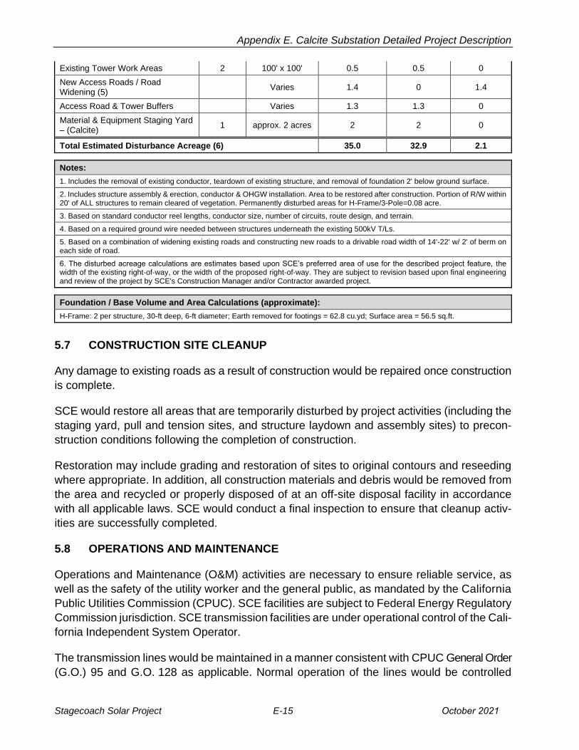
5.6 LAND DISTURBANCE
Table SCE-4 below provides information on temporary and permanent land disturbance
areas related to construction of the transmission loop-in lines and SCE portion of gen-tie
construction.
Table SCE-4. Land Disturbance for Transmission Loop-in and SCE Portion of Gen-tie Construction
Project Feature Project
Quantity
Disturbed Acreage
Calculation
Construction Disturbance
Acreage
Temporary Disturbance
Acreage
Permanent Disturbance
Acreage
Guard Structures 4 150' x 50' 0.7 0.7 0
Remove Existing Lattice Steel Towers (1)
2 220' x 220' 2.2 2.2 0
Construct New TSPs (2) 5 220' x 220' 5.6 5.2 0.4
Construct New Steel Pole H-frames (2)
4 220' x 220' 4.4 4.1 0.3
220kV Conductor Stringing Areas (3)
12 400' x 150' 16.5 16.5 0
Install Underground Ground Wire (4)
1,100 linear feet x 15’
wide 0.4 0.4 0
October 2021 E-14 Stagecoach Solar Project Draft EIR
Appendix E. Calcite Substation Detailed Project Description
Existing Tower Work Areas 2 100' x 100' 0.5 0.5 0
New Access Roads / Road Widening (5)
Varies 1.4 0 1.4
Access Road & Tower Buffers Varies 1.3 1.3 0
Material & Equipment Staging Yard – (Calcite)
1 approx. 2 acres 2 2 0
Total Estimated Disturbance Acreage (6) 35.0 32.9 2.1
Notes:
1. Includes the removal of existing conductor, teardown of existing structure, and removal of foundation 2' below ground surface.
2. Includes structure assembly & erection, conductor & OHGW installation. Area to be restored after construction. Portion of R/W within20' of ALL structures to remain cleared of vegetation. Permanently disturbed areas for H-Frame/3-Pole=0.08 acre.
3. Based on standard conductor reel lengths, conductor size, number of circuits, route design, and terrain.
4. Based on a required ground wire needed between structures underneath the existing 500kV T/Ls.
5. Based on a combination of widening existing roads and constructing new roads to a drivable road width of 14'-22' w/ 2' of berm oneach side of road.
6. The disturbed acreage calculations are estimates based upon SCE’s preferred area of use for the described project feature, thewidth of the existing right-of-way, or the width of the proposed right-of-way. They are subject to revision based upon final engineeringand review of the project by SCE's Construction Manager and/or Contractor awarded project.
Foundation / Base Volume and Area Calculations (approximate):
H-Frame: 2 per structure, 30-ft deep, 6-ft diameter; Earth removed for footings = 62.8 cu.yd; Surface area = 56.5 sq.ft.
5.7 CONSTRUCTION SITE CLEANUP
Any damage to existing roads as a result of construction would be repaired once construction
is complete.
SCE would restore all areas that are temporarily disturbed by project activities (including the
staging yard, pull and tension sites, and structure laydown and assembly sites) to precon
struction conditions following the completion of construction.
Restoration may include grading and restoration of sites to original contours and reseeding
where appropriate. In addition, all construction materials and debris would be removed from
the area and recycled or properly disposed of at an off-site disposal facility in accordance
with all applicable laws. SCE would conduct a final inspection to ensure that cleanup activ
ities are successfully completed.
5.8 OPERATIONS AND MAINTENANCE
Operations and Maintenance (O&M) activities are necessary to ensure reliable service, as
well as the safety of the utility worker and the general public, as mandated by the California
Public Utilities Commission (CPUC). SCE facilities are subject to Federal Energy Regulatory
Commission jurisdiction. SCE transmission facilities are under operational control of the Cali
fornia Independent System Operator.
The transmission lines would be maintained in a manner consistent with CPUC General Order
(G.O.) 95 and G.O. 128 as applicable. Normal operation of the lines would be controlled
Stagecoach Solar Project E-15 October 2021
Appendix E. Calcite Substation Detailed Project Description
remotely through SCE control systems and manually, in the field, as required. SCE inspects
overhead transmission facilities in a manner consistent with CPUC G.O. 165 a minimum of
once per year via ground and/or aerial observation, but this usually occurs more frequently
based on system reliability.
Maintenance is performed as needed to maintain circuit reliability. A majority of regular O&M
activities related to overhead facilities are performed from existing access roads with no
surface disturbance. These activities could include repairing/re-stringing conductors to repair
damage, washing/replacing insulators, repairing/replacing hardware components, replacing
poles/towers, tree trimming, brush and weed control, and access road maintenance. Repairs
to existing facilities, such as repairing/replacing existing poles/towers or conductor re
stringing, could occur in undisturbed areas.
Routine access road maintenance is conducted on an annual and/or as-needed basis to
maintain a vegetation-free corridor to facilitate access to existing facilities and to aide in fire
prevention. Road maintenance activities could include: blading to smooth over washouts,
eroded areas, and washboard surfaces; cleaning ditches; moving/establishing berms; clear
ing/installing functional drain inlets to culverts; repairing culverts; clearing/establishing water
bars; and cleaning/repairing over-side drains. Access road maintenance could include the
repair, replacement and/or installation of storm water diversion devices on an as-needed
basis.
O&M activities could also include brushing activities in order to maintain vegetation-free
access roads and clearances around electrical lines. Brushing (i.e., trimming or shrub
removal) approximately two to five feet beyond road’s edge or berm is necessary to keep
vegetation from intruding into the roadway. In addition, the clearance of brush and weeds
around pole and transmission tower pads is necessary for fire protection and may be
required by applicable regulations on fee owned ROWs. In accordance with Public Resources
Code section 4292, a 10-foot radial clearance around non-exempt poles and towers (as
defined by California Code of Regulations Title 14, Division 1.5, Ch 7, Article 4) would be
maintained.
In addition to regular O&M activities, emergency repairs could be required at any time. SCE
conducts a wide variety of emergency infrastructure repairs due to damage resulting from
high winds, storms, fires, and other natural disasters and accidents. Such repairs could include
replacement of towers, poles, or conductors.
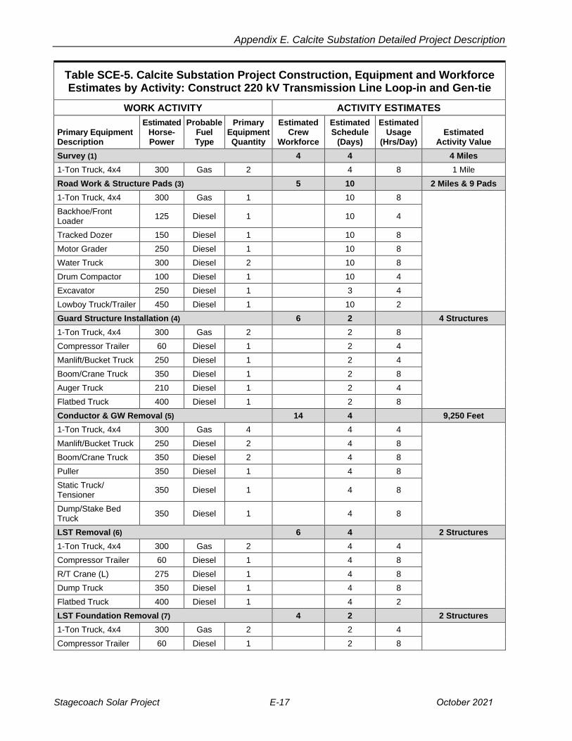
5.9 LABOR AND EQUIPMENT
Construction would be performed by SCE Crews or its contract personnel. The estimated
number of persons and types of equipment required for each phase of transmission line con
struction is shown in Table SCE-5 below.
October 2021 E-16 Stagecoach Solar Project Draft EIR
Appendix E. Calcite Substation Detailed Project Description
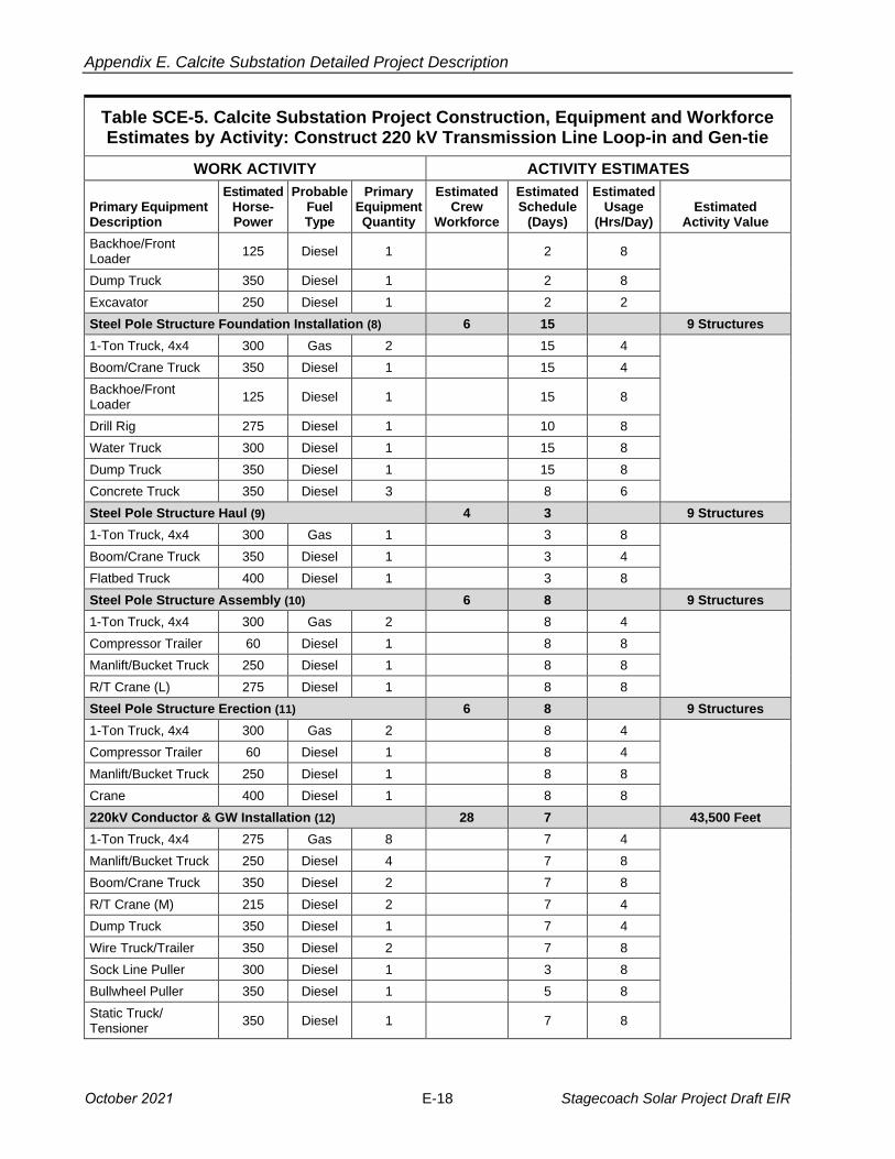
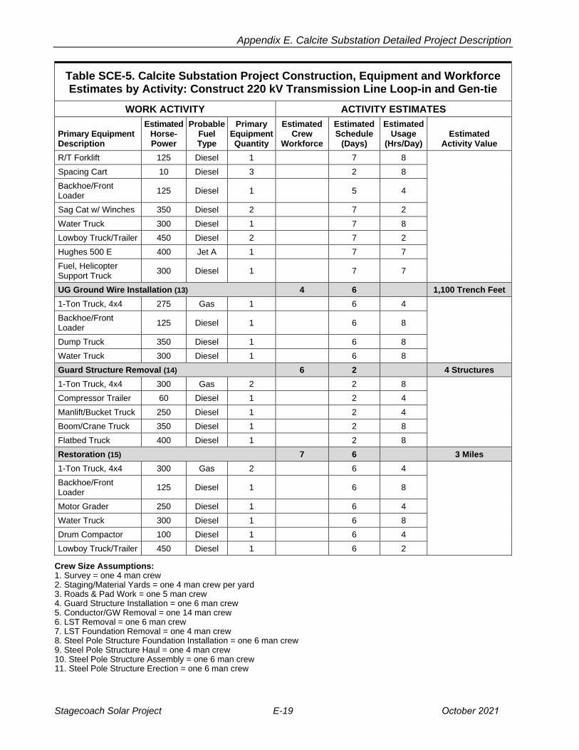
Table SCE-5. Calcite Substation Project Construction, Equipment and Workforce Estimates by Activity: Construct 220 kV Transmission Line Loop-in and Gen-tie
WORK ACTIVITY ACTIVITY ESTIMATES
Primary Equipment Description
Estimated Horse-Power
Probable Fuel Type
Primary Equipment Quantity
Estimated Crew
Workforce
Estimated Schedule
(Days)
Estimated Usage
(Hrs/Day) Estimated
Activity Value
Survey (1) 4 4 4 Miles
1-Ton Truck, 4x4 300 Gas 2 4 8 1 Mile
Road Work & Structure Pads (3) 5 10 2 Miles & 9 Pads
1-Ton Truck, 4x4 300 Gas 1 10 8
Backhoe/Front Loader
125 Diesel 1 10 4
Tracked Dozer 150 Diesel 1 10 8
Motor Grader 250 Diesel 1 10 8
Water Truck 300 Diesel 2 10 8
Drum Compactor 100 Diesel 1 10 4
Excavator 250 Diesel 1 3 4
Lowboy Truck/Trailer 450 Diesel 1 10 2
Guard Structure Installation (4) 6 2 4 Structures
1-Ton Truck, 4x4 300 Gas 2 2 8
Compressor Trailer 60 Diesel 1 2 4
Manlift/Bucket Truck 250 Diesel 1 2 4
Boom/Crane Truck 350 Diesel 1 2 8
Auger Truck 210 Diesel 1 2 4
Flatbed Truck 400 Diesel 1 2 8
Conductor & GW Removal (5) 14 4 9,250 Feet
1-Ton Truck, 4x4 300 Gas 4 4 4
Manlift/Bucket Truck 250 Diesel 2 4 8
Boom/Crane Truck 350 Diesel 2 4 8
Puller 350 Diesel 1 4 8
Static Truck/ Tensioner
350 Diesel 1 4 8
Dump/Stake Bed Truck
350 Diesel 1 4 8
LST Removal (6) 6 4 2 Structures
1-Ton Truck, 4x4 300 Gas 2 4 4
Compressor Trailer 60 Diesel 1 4 8
R/T Crane (L) 275 Diesel 1 4 8
Dump Truck 350 Diesel 1 4 8
Flatbed Truck 400 Diesel 1 4 2
LST Foundation Removal (7) 4 2 2 Structures
1-Ton Truck, 4x4 300 Gas 2 2 4
Compressor Trailer 60 Diesel 1 2 8
Stagecoach Solar Project E-17 October 2021
Appendix E. Calcite Substation Detailed Project Description
Table SCE-5. Calcite Substation Project Construction, Equipment and Workforce Estimates by Activity: Construct 220 kV Transmission Line Loop-in and Gen-tie
WORK ACTIVITY ACTIVITY ESTIMATES
Primary Equipment Description
Estimated Horse-Power
Probable Fuel Type
Primary Equipment Quantity
Estimated Crew
Workforce
Estimated Schedule
(Days)
Estimated Usage
(Hrs/Day) Estimated
Activity Value
Backhoe/Front Loader
125 Diesel 1 2 8
Dump Truck 350 Diesel 1 2 8
Excavator 250 Diesel 1 2 2
Steel Pole Structure Foundation Installation (8) 6 15 9 Structures
1-Ton Truck, 4x4 300 Gas 2 15 4
Boom/Crane Truck 350 Diesel 1 15 4
Backhoe/Front Loader
125 Diesel 1 15 8
Drill Rig 275 Diesel 1 10 8
Water Truck 300 Diesel 1 15 8
Dump Truck 350 Diesel 1 15 8
Concrete Truck 350 Diesel 3 8 6
Steel Pole Structure Haul (9) 4 3 9 Structures
1-Ton Truck, 4x4 300 Gas 1 3 8
Boom/Crane Truck 350 Diesel 1 3 4
Flatbed Truck 400 Diesel 1 3 8
Steel Pole Structure Assembly (10) 6 8 9 Structures
1-Ton Truck, 4x4 300 Gas 2 8 4
Compressor Trailer 60 Diesel 1 8 8
Manlift/Bucket Truck 250 Diesel 1 8 8
R/T Crane (L) 275 Diesel 1 8 8
Steel Pole Structure Erection (11) 6 8 9 Structures
1-Ton Truck, 4x4 300 Gas 2 8 4
Compressor Trailer 60 Diesel 1 8 4
Manlift/Bucket Truck 250 Diesel 1 8 8
Crane 400 Diesel 1 8 8
220kV Conductor & GW Installation (12) 28 7 43,500 Feet
1-Ton Truck, 4x4 275 Gas 8 7 4
Manlift/Bucket Truck 250 Diesel 4 7 8
Boom/Crane Truck 350 Diesel 2 7 8
R/T Crane (M) 215 Diesel 2 7 4
Dump Truck 350 Diesel 1 7 4
Wire Truck/Trailer 350 Diesel 2 7 8
Sock Line Puller 300 Diesel 1 3 8
Bullwheel Puller 350 Diesel 1 5 8
Static Truck/ Tensioner
350 Diesel 1 7 8
October 2021 E-18 Stagecoach Solar Project Draft EIR
Appendix E. Calcite Substation Detailed Project Description
Table SCE-5. Calcite Substation Project Construction, Equipment and Workforce Estimates by Activity: Construct 220 kV Transmission Line Loop-in and Gen-tie
WORK ACTIVITY ACTIVITY ESTIMATES
Primary Equipment Description
Estimated Horse-Power
Probable Fuel Type
Primary Equipment Quantity
Estimated Crew
Workforce
Estimated Schedule
(Days)
Estimated Usage
(Hrs/Day) Estimated
Activity Value
R/T Forklift 125 Diesel 1 7 8
Spacing Cart 10 Diesel 3 2 8
Backhoe/Front Loader
125 Diesel 1 5 4
Sag Cat w/ Winches 350 Diesel 2 7 2
Water Truck 300 Diesel 1 7 8
Lowboy Truck/Trailer 450 Diesel 2 7 2
Hughes 500 E 400 Jet A 1 7 7
Fuel, Helicopter Support Truck
300 Diesel 1 7 7
UG Ground Wire Installation (13) 4 6 1,100 Trench Feet
1-Ton Truck, 4x4 275 Gas 1 6 4
Backhoe/Front Loader
125 Diesel 1 6 8
Dump Truck 350 Diesel 1 6 8
Water Truck 300 Diesel 1 6 8
Guard Structure Removal (14) 6 2 4 Structures
1-Ton Truck, 4x4 300 Gas 2 2 8
Compressor Trailer 60 Diesel 1 2 4
Manlift/Bucket Truck 250 Diesel 1 2 4
Boom/Crane Truck 350 Diesel 1 2 8
Flatbed Truck 400 Diesel 1 2 8
Restoration (15) 7 6 3 Miles
1-Ton Truck, 4x4 300 Gas 2 6 4
Backhoe/Front Loader
125 Diesel 1 6 8
Motor Grader 250 Diesel 1 6 4
Water Truck 300 Diesel 1 6 8
Drum Compactor 100 Diesel 1 6 4
Lowboy Truck/Trailer 450 Diesel 1 6 2
Crew Size Assumptions: 1. Survey = one 4 man crew2. Staging/Material Yards = one 4 man crew per yard3. Roads & Pad Work = one 5 man crew4. Guard Structure Installation = one 6 man crew5. Conductor/GW Removal = one 14 man crew6. LST Removal = one 6 man crew7. LST Foundation Removal = one 4 man crew8. Steel Pole Structure Foundation Installation = one 6 man crew9. Steel Pole Structure Haul = one 4 man crew10. Steel Pole Structure Assembly = one 6 man crew11. Steel Pole Structure Erection = one 6 man crew
Stagecoach Solar Project E-19 October 2021
Appendix E. Calcite Substation Detailed Project Description
12. Conductor & GW Installation = one 28 man crew13. UG Ground Wire Installation = one 4 man crew14. Guard Structure Removal = one 6 man crew15. Restoration = one 7 man crew
6. DISTRIBUTION SYSTEM FOR STATION LIGHT AND POWER
6.1 DISTRIBUTION FOR CALCITE SUBSTATION
An extension of a 12 kV distribution circuit would be required to provide permanent station
light and power and/or temporary power for construction for Calcite Substation. The 12kV
distribution circuitry would be extended for approximately 700 feet by installing approxi
mately 6 wood poles. See Figure SCE-1, Proposed Calcite Substation; Figure SCE-5, Pole
Configuration; and Figure SCE-6, Pole and Crossarm Configuration with Raptor Guard.
The 12 kV distribution circuit would then extend underground heading west along Haynes
Road under the existing California Highway 247 and transmission Right of Way (ROW) and
then turn north along the Calcite Substation driveway and into Calcite Substation. The total
underground circuit extension length would be approximately 3,100 feet. These new facilities
would also be utilized for installation of the required telecommunication fiber optic cables
into Calcite Substation (described below in Section IV. Telecommunication Facilities).
Circuit modification may be required to provide support for voltage regulating requirements
such as new capacitors or voltage regulators. A pad-mount transformer would be installed
on the Calcite Substation Property outside the Calcite Substation for temporary construction
power. Additionally, new station light and power transformers would be installed within the
Calcite Substation fence.
Materials needed for distribution construction activities would be stored at the proposed
staging yard within the Calcite Substation Property described above. Two-line trucks with
three-person crews (6 people total) would be called upon to perform the work.
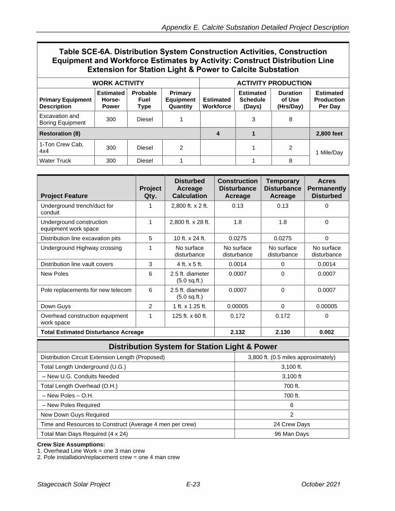
6.2 CONSTRUCTION ACTIVITIES FOR DISTRIBUTION LINES AND RELATED
STRUCTURES
For the locations that require overhead construction, components would be shipped by truck
to the staging yard and then trucked to the individual sites. Poles and associated equipment
would then be erected along the required routes. The permanent ground disturbance for
each pole installation would be approximately 4.9 sq.ft. per pole and 0.1 sq.ft. per pole
anchor. At some structure locations, vegetation may be removed and/or trimmed to accom
modate the installation of overhead and/or underground distribution facilities. See Table
SCE-6A for details.
Wire stringing includes all activities associated with installation of the distribution circuit con
ductors onto the distribution poles. This would include the installation of primary conductor,
October 2021 E-20 Stagecoach Solar Project Draft EIR

Appendix E. Calcite Substation Detailed Project Description
insulators, and dead-end hardware assemblies. These installations may also include vibra
tion dampeners, weights, spacers and fault indicators. Insulators and stringing sheaves
(rollers or travelers) may be attached to the conductors as part of the stringing activity, during
the distribution pole erection process. The dimensions of the area needed for the stringing
setups associated with conductor installation will vary depending on structure height and
terrain conditions, but will not extend beyond the limits of the temporary construction use
areas. At some wire stringing locations, vegetation may be removed and/or trimmed to
accommodate the wiring stringing process.
For the locations that require the construction of a trench or underground structure, excava
tion activities would generally be done using a backhoe. The anticipated dimensions for the
trench would be approximately 24 inches wide by approximately 51 inches deep, and by the
lengths identified earlier in this section. Shields or trench shoring would then be temporarily
installed for safety to brace the walls of the trench. The conduits would then be installed
using spacers to create a duct bank consisting of two columns of three stacked 5-inch con
duits a piece. The temporary shoring would be removed.
Underground structure excavation would typically be a maximum of three feet greater than
the structure’s width and length dimensions, as well as a maximum of four feet deeper than
the structure’s height. The backhoe would be used to place the excavated soil into the dump truck to haul away. The area of disturbance would be approximately 30 feet on either side
of trench and on all sides of the underground structures. The conduits would then be
encased in concrete with a minimum encasement of three inches on all sides. After the
concrete encasement has hardened, the trench would be backfilled with 1.5 sack and sand
slurry (which is a mix of sand and water with 1.5 bags of cement added with no aggregate).
If repaving is necessary, this work would be performed in accordance with San Bernardino
County permit requirements. Precast underground structures would typically be installed
and backfilled with slurry.
Table SCE-6A. Distribution System Construction Activities, Construction Equipment and Workforce Estimates by Activity: Construct Distribution Line
Extension for Station Light & Power to Calcite Substation
WORK ACTIVITY ACTIVITY PRODUCTION
Primary Equipment Description
Estimated Horse-Power
Probable Fuel Type
Primary Equipment
Quantity Estimated Workforce
Estimated Schedule
(Days)
Duration of Use
(Hrs/Day)
Estimated Production
Per Day
Install Down Guys (1) 3 2 Approx 2 Down Guys
1-Ton Crew CabFlatbed, 4x4
300 Diesel 1 2 8 1 Down Guy/ Day
Bucket Truck 300 Diesel 1 2 8
Install New Poles (2) 4 6 12 Wood
Poles
1-Ton Pickup Truck,4x4
300 Diesel 2 6 8 2 Wood
Pole/Day
Stagecoach Solar Project E-21 October 2021

Appendix E. Calcite Substation Detailed Project Description
Table SCE-6A. Distribution System Construction Activities, Construction Equipment and Workforce Estimates by Activity: Construct Distribution Line
Extension for Station Light & Power to Calcite Substation
WORK ACTIVITY ACTIVITY PRODUCTION
Primary Equipment Description
Estimated Horse-Power
Probable Fuel Type
Primary Equipment
Quantity Estimated Workforce
Estimated Schedule
(Days)
Duration of Use
(Hrs/Day)
Estimated Production
Per Day
30-Ton Crane Truck 300 Diesel 1 6 8
Bucket Truck 300 Diesel 2 6 8
40' Flatbed Truck/ Trailer
350 Diesel 1 6 8
Install Overhead Wire (3) 6 1 700 Circuit
Feet
1-Ton Crew CabPickup Truck, 4x4
300 Diesel 1 1 8 1,000
Feet/Day 55’ Double Bucket Truck
350 Diesel 1 1 8
Underground Cable Pulling & Transformer Installation (4) 4 3 3,100
Circuit Feet
1-Ton Pickup Truck,4x4
300 Diesel 1 3 8
1,000 Feet/Day
55’ Double Bucket Truck
350 Diesel 1 3 8
Hydraulic Rewind Puller
300 Diesel 1 3 8
Underground Cable Makeup (5) 4 2
1-Ton Crew Cab,4x4
300 Diesel 1 2 8
55’ Double Bucket Truck
350 Diesel 1
Underground Trenching, Structure Excavation Conduit (6) 4 6 Approx. 2,800 ft.
1-Ton Pickup Truck,4x4
300 Diesel 1 6 8
500 Feet/Day
Backhoe/Front Loader
200 Diesel 1 6 8
1-Ton Crew CabFlatbed, 4x4
300 Diesel 1 6 8
4000 gallon Water Truck
350 Diesel 1 6 8
Concrete Truck 350 Diesel 1 6 8
Underground Boring, Casing and Conduit Installation (7) 6 3 Approx.
300 ft.
1-Ton Pickup Truck,4x4
300 Diesel 1 3 8
100 Feet/Day
Backhoe/Front Loader
200 Diesel 1 3 8
1-Ton Crew CabFlatbed, 4x4
300 Diesel 1 3 8
October 2021 E-22 Stagecoach Solar Project Draft EIR
Appendix E. Calcite Substation Detailed Project Description
Table SCE-6A. Distribution System Construction Activities, Construction Equipment and Workforce Estimates by Activity: Construct Distribution Line
Extension for Station Light & Power to Calcite Substation
WORK ACTIVITY ACTIVITY PRODUCTION
Primary Equipment Description
Estimated Horse-Power
Probable Fuel Type
Primary Equipment
Quantity Estimated Workforce
Estimated Schedule
(Days)
Duration of Use
(Hrs/Day)
Estimated Production
Per Day
Excavation and Boring Equipment
300 Diesel 1 3 8
Restoration (8) 4 1 2,800 feet
1-Ton Crew Cab,4x4
300 Diesel 2 1 2 1 Mile/Day
Water Truck 300 Diesel 1 1 8
Project Feature Project
Qty.
Disturbed Acreage
Calculation
Construction Disturbance
Acreage
Temporary Disturbance
Acreage
Acres Permanently
Disturbed
Underground trench/duct for conduit
1 2,800 ft. x 2 ft. 0.13 0.13 0
Underground construction equipment work space
1 2,800 ft. x 28 ft. 1.8 1.8 0
Distribution line excavation pits 5 10 ft. x 24 ft. 0.0275 0.0275 0
Underground Highway crossing 1 No surface disturbance
No surface disturbance
No surface disturbance
No surface disturbance
Distribution line vault covers 3 4 ft. x 5 ft. 0.0014 0 0.0014
New Poles 6 2.5 ft. diameter (5.0 sq.ft.)
0.0007 0 0.0007
Pole replacements for new telecom 6 2.5 ft. diameter (5.0 sq.ft.)
0.0007 0 0.0007
Down Guys 2 1 ft. x 1.25 ft. 0.00005 0 0.00005
Overhead construction equipment work space
1 125 ft. x 60 ft. 0.172 0.172 0
Total Estimated Disturbance Acreage 2.132 2.130 0.002
Distribution System for Station Light & Power
Distribution Circuit Extension Length (Proposed) 3,800 ft. (0.5 miles approximately)
Total Length Underground (U.G.) 3,100 ft.
– New U.G. Conduits Needed 3,100 ft
Total Length Overhead (O.H.) 700 ft.
– New Poles – O.H. 700 ft.
– New Poles Required 6
New Down Guys Required 2
Time and Resources to Construct (Average 4 men per crew) 24 Crew Days
Total Man Days Required (4 x 24) 96 Man Days
Crew Size Assumptions: 1. Overhead Line Work = one 3 man crew2. Pole installation/replacement crew = one 4 man crew
Stagecoach Solar Project E-23 October 2021

Appendix E. Calcite Substation Detailed Project Description
3. Overhead Line Work = two 3 man crews4. Underground Cable Pulling = one 4 man crew5. Underground Cable Makeup = one 4 man crew6. Trenching and Conduit Installation = one 4 man crew7. Trenching and Underground Boring = one 6 man crew8. Trenching Backfill and Restoration = one 4 man crew
7. TELECOMMUNICATION FACILITIES
A telecommunication system would be required to provide monitoring and remote operation
capabilities of the electrical equipment at Calcite Substation, transmission line protection,
and Remedial Action Scheme (or “RAS”)3 .
The SCE telecommunication facilities expected to be constructed as part of the Calcite
Substation Project would include two approximately 1-mile long fiber optic cables to the
nearest splice points on an OPGW that is expected to already be in place on the 500kV
Lugo-Mohave T/L by the time any work associated with the Calcite Substation Project
commences.4 See Figure SCE-1, Proposed Calcite Substation.
The first proposed fiber optic cable would start from Calcite Substation and would be installed
along the new 12 kV distribution path as previously described in Section III, including the
new underground section under the CA 247 Hwy and along Haynes Road, and then
overhead along a new telecommunications and distribution pole line. The proposed line
turns north along an un-named dirt road for approximately 1,000 feet attaching to existing
wood poles and arriving at the Barstow Repeater Communication Site (“CS”). The line would
3 RASs are “protective systems that typically utilize a combination of conventional protective relays, computer-based processors, and telecommunications to accomplish rapid, automated response (including outages) to unplanned power system events” (CAISO Master Definition Supplement, available at: http://caiso.com/rules/ Pages/Regulatory/Default.aspx). Currently, there is an existing High Desert Power Plant (HDPP) RAS that is in place and the Stagecoach Solar Project would be required to participate in the HDPP RAS (as well as be subject to CAISO’s congestion management protocols that could be implemented by CAISO) at the outset. In addition, SCE is also in the process of preparing to develop the North of Lugo Centralized RAS (NoL CRAS) to replace the existing HDPP RAS and other RASs in the area, as a distinct and independent project being separately undertaken irrespective of, and with independent utility from, the Calcite Substation Project. Once the NoL CRAS is complete, both Calcite Substation and the Stagecoach Solar Project would participate in the NoL CRAS instead of the HDPP RAS. All CRAS conversion work is limited to installing equipment within the MEER building.
4 That OPGW is expected to be in place as a result of the anticipated completion of SCE’s Eldorado Lugo Mohave Series Capacitors (ELM) Project. The ELM Project is a distinct and independent project being separately undertaken by SCE that has independent utility from the Calcite Substation Project and was approved by the CPUC on August 27, 2020. Completion and operation of the ELM Project would include OPGW which would be tapped in order to connect to the proposed Calcite Substation. Similarly, SCE also has another distinct and independent project with telecommunications equipment that, if constructed, would obviate the need to construct any other telecommunication facilities to support the Calcite Substation, namely, the Lugo-Victorville 500kV Remedial Action Scheme Project (LVRAS Project). In fact, SCE has already submitted a Standard Form 299 application to the U.S. Bureau of Land Management for authorization to complete the LVRAS Project, which also has independent utility from the Calcite Substation Project. Assuming that both the ELM Project and the LVRAS Project currently planned by SCE are constructed and placed into operation prior to the operation of Calcite Substation, SCE would not need to construct any further telecommunication facilities to support the Calcite Substation (other than the two 1-mile taps described above).
October 2021 E-24 Stagecoach Solar Project Draft EIR
Appendix E. Calcite Substation Detailed Project Description
drop down into a new riser and continues underground for approximately 750 feet into an
existing communication room within the CS.
The second proposed fiber optic cable would start from Calcite Substation and exit the
substation to the south for approximately 400 feet in new underground conduit and then turn
east onto Haynes Road for approximately 1,200 feet. The conduit would turn south-west on
an existing access road for approximately 4,000 feet and then turn northwest to get to tower
M29-T3 on the Lugo-Mohave T/L where the existing splice box is located. This underground
conduit route would be built exclusively for telecommunications use.
7.1 TELECOMMUNICATION GEN-TIE CABLES
The first proposed telecommunication gen-tie cable route will be an OPGW fiber optic cable
installed by the customer from the customer’s substation on the gen-tie 220 kV structures.
The OPGW would end at a splice enclosure on the first customer-owned structure outside
the Calcite Substation. Underground conduit and cable would be installed by the customer
from the transmission POCO with the OPGW splice to the telecommunication POCO vault
outside the wall of the Calcite Substation. The customer would a leave a 100’ coil of cable in the POCO vault. An SCE crew would use the coil for making the demarcation splice in the
POCO vault. SCE will install approximately 1,000 feet of conduit and cable from the POCO
vault to the MEER. See Figure SCE-1, Proposed Calcite Substation.
The diverse telecommunication gen-tie cable route would be an underground fiber optic
cable installed by the customer in the gen-tie 220kV right of way. The conduit with this under
ground cable would connect to the diverse POCO vault outside the Calcite Substation. A
coil of 100’ of the cable would be left in the diverse POCO vault for making the demarcation splice. SCE will install approximately 1,000 feet of conduit and cable from the diverse POCO
vault to the MEER and make the demarcation splice.
The above description is based on our preliminary design and would be finalized as part of
final engineering.
7.2 TELECOMMUNICATIONS EQUIPMENT
• New overhead/underground 96-strand fiber optic cable to connect the Calcite Sub
station to Barstow Repeater CS. New overhead/underground 96-strand fiber optic
cables to connect Calcite Substation to an existing splice box on M29-T3 on Lugo
Mohave 500kV T/L.
• The Calcite Substation MEER would also include a communication room for telecom
munication equipment. The communication room would be equipped with AC power,
AC-DC rectifiers, DC power, battery, overhead cable tray, redundant air conditioners,
fiber terminating shelves, lightwave terminals, channel equipment, communications
alarm/switch equipment, data equipment and diverse fiber entry conduits for connec
tion to outside plant fiber optic cables.
Stagecoach Solar Project E-25 October 2021

Appendix E. Calcite Substation Detailed Project Description
• New fiber optic multiplex equipment and channel equipment at Lugo, Pisgah, Victor,
Kramer and Gale Substations and any other location necessary to support the com
munication requirements for the Calcite Substation Project.
• Replacement of existing poles if required, to be determined by final engineering.
7.3 LAYDOWN AREAS AND ACCESS ROADS
Laydown areas may include the following existing SCE facilities.
• Victorville Service Center – Hesperia Road, Victorville
• Apple Valley Sub – Deep Creek Road, Apple Valley
• Calcite Substation Property – Barstow Road (Hwy. 247), Lucerne Valley
• Barstow Service Center – Rimrock Road, Barstow
7.4 CONSTRUCTION ACTIVITIES
SCE or its contractor crews would use standard construction methods to construct the
required fiber optic cables. The crews would comply with all rules, regulations and standards
while in their performance of the construction phase. Portions of the fiber optic cable would
be constructed on existing overhead distribution and transmission wood and light duty steel
poles. In addition, portions of the cable would be constructed on new overhead structures
and newly constructed underground conduit system(s), subject to determination through
final engineering. This project description is based on planning level assumptions. Exact
details would be determined following completion of preliminary and final engineering, iden
tification of field conditions, availability of labor, material, and equipment, and compliance with
applicable environmental and permitting requirements.
Generally no hazardous material would be used in installing underground conduit, new wood
communication poles, and the stringing of fiber-optic cables. There is generally no need for
local services or utilities (such as water). Waste generated (which typically would include
empty cable reels, cut-off pieces of fiber cable) would be disposed of at existing SCE
facilities.
The cable crew would use existing roads or previously established roads to proceed with
the function of cable installation when possible. Workforce estimates, equipment details, and
disturbance totals are provided in Tables SCE-7A through SCE-7H.
7.5 INSTALLATION OF FIBER OPTIC CABLE ON POLES
The overhead fiber optic cable SCE installs is a type of cable known as All Dielectric Self-
supporting Fiber Optic Cable (ADSS). Usually this cable is installed with the use of a bucket
truck. One four-man crew and two trucks would be used. A crew can install up to 1,000 feet
of cable in one day. A crew can complete one 96 fiber splice in a day.
October 2021 E-26 Stagecoach Solar Project Draft EIR

Appendix E. Calcite Substation Detailed Project Description
ADSS stringing includes all activities associated with the installation of cables on existing
wood pole or Light Weight Steel (LWS) structures. This activity includes the installation of
cross arms, suspension and dead-end hardware assemblies and vibration dampeners,
stringing sheaves (rollers or travelers) may be used when installing the cable. Advanced
planning by supervision determines pulling locations, times, and safety protocols needed for
ensuring that safe and quick installation of cable is accomplished.
Fiber optic cable pulls typically occur every 5,000 feet to 20,000 feet over flat or mountainous
terrain. Fiber optic cable pulls are based on access for pulling equipment to designated
dead-end structures, terrain, and suitability for fiber optic cable splicing equipment set ups.
The dimensions of the area needed for stringing set ups varies depending upon the terrain;
however, a typical stringing set up is 40 feet by 60 feet. Where necessary due to space
limitations, crews can work from within a smaller area.
A distribution line pole would be replaced if the pole does not meet wind load specifications.
Inter-set poles may be added to spans where needed to achieve required ground clearance
for the fiber optic cable. Replacing distribution line pole requires a four-man crew, one pole
trailer truck, one pole digger truck, and one crew truck. An approximate 30-foot x 40-foot
work area is required for the work. A hole about eight feet in depth would be drilled next to
the existing pole, and a new pole would be erected. Conductors would be transferred from
the existing pole to the new pole and the old pole removed.
7.6 INSTALLATION OF FIBER OPTIC CABLE IN CONDUIT
For the installation of the fiber optic cable in existing and new underground conduit, a high-
density polyethylene smooth wall innerduct would be used. Innerduct facilitates the installa
tion of the fiber optic cable, provides protection, and helps identify the cable. The innerduct
is installed first inside the conduit between underground vaults. The fiber optic cable is then
installed inside the innerduct. An approximate 30-foot x 40-foot work area is required at each
vault to install the underground cable. A coil of 100’ of cable is left on each cable end in the
vault for splicing.
7.7 SPLICING FIBER OPTIC CABLE
For splicing fiber optic cables, Outside Plant Splicing Labs and Foreman Trucks would be
used. The workspace required would be an approximate 30-foot by 40-foot area. The crew
would bring the fiber optic cable ends into the Splice Lab and splice together the fibers from
the two cables. After the fibers are spliced and secured in a splice case, the splice case and
cable slack would be mounted on a cross arms on a pole or attached to the side wall of an
underground vault. Because of the rigid nature of OPGW, the splice case is placed inside a
splice cabinet mounted on a lattice tower and the OPGW stored in a coil around the cabinet.
Stagecoach Solar Project E-27 October 2021
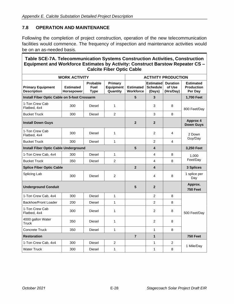
Appendix E. Calcite Substation Detailed Project Description
7.8 OPERATION AND MAINTENANCE
Following the completion of project construction, operation of the new telecommunication
facilities would commence. The frequency of inspection and maintenance activities would
be on an as-needed basis.
Table SCE-7A. Telecommunication Systems Construction Activities, Construction Equipment and Workforce Estimates by Activity: Construct Barstow Repeater CS –
Calcite Fiber Optic Cable
WORK ACTIVITY ACTIVITY PRODUCTION
Primary Equipment Description
Estimated Horsepower
Probable Fuel Type
Primary Equipment
Quantity Estimated Workforce
Estimated Schedule
(Days)
Duration of Use
(Hrs/Day)
Estimated Production
Per Day
Install Fiber Optic Cable on 5-foot Crossarm 5 3 1,700 Feet
1-Ton Crew CabFlatbed, 4x4
300 Diesel 1 3 8 800 Feet/Day
Bucket Truck 300 Diesel 2 3 8
Install Down Guys 2 2 Approx 4
Down Guys
1-Ton Crew CabFlatbed, 4x4
300 Diesel 1 2 4 2 Down Guy/Day
Bucket Truck 300 Diesel 1 2 4
Install Fiber Optic Cable Underground 5 4 3,250 Feet
1-Ton Crew Cab, 4x4 300 Diesel 1 4 8 1,000 Feet/Day Bucket Truck 350 Diesel 2 4 8
Splice Fiber Optic Cable 2 4 3 Splices
Splicing Lab 300 Diesel 2 4 8
1 splice per Day
Underground Conduit 5 2 Approx.
750 Feet
1-Ton Crew Cab, 4x4 300 Diesel 1 2 8
500 Feet/Day
Backhoe/Front Loader 200 Diesel 1 2 8
1-Ton Crew CabFlatbed, 4x4
300 Diesel 1 2 8
4000 gallon Water Truck
350 Diesel 1 2 8
Concrete Truck 350 Diesel 1 1 8
Restoration 7 1 750 Feet
1-Ton Crew Cab, 4x4 300 Diesel 2 1 2 1 Mile/Day
Water Truck 300 Diesel 1 1 8
October 2021 E-28 Stagecoach Solar Project Draft EIR
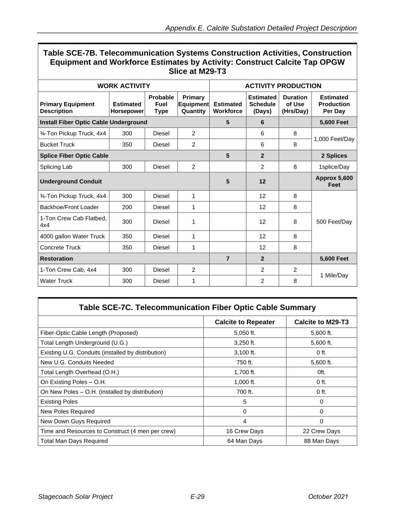
Appendix E. Calcite Substation Detailed Project Description
Table SCE-7B. Telecommunication Systems Construction Activities, Construction Equipment and Workforce Estimates by Activity: Construct Calcite Tap OPGW
Slice at M29-T3
WORK ACTIVITY ACTIVITY PRODUCTION
Primary Equipment Description
Estimated Horsepower
Probable Fuel Type
Primary Equipment
Quantity Estimated Workforce
Estimated Schedule
(Days)
Duration of Use
(Hrs/Day)
Estimated Production
Per Day
Install Fiber Optic Cable Underground 5 6 5,600 Feet
¾-Ton Pickup Truck, 4x4 300 Diesel 2 6 8 1,000 Feet/Day
Bucket Truck 350 Diesel 2 6 8
Splice Fiber Optic Cable 5 2 2 Splices
Splicing Lab 300 Diesel 2 2 8 1splice/Day
Underground Conduit 5 12 Approx 5,600
Feet
¾-Ton Pickup Truck, 4x4 300 Diesel 1 12 8
500 Feet/Day
Backhoe/Front Loader 200 Diesel 1 12 8
1-Ton Crew Cab Flatbed,4x4
300 Diesel 1 12 8
4000 gallon Water Truck 350 Diesel 1 12 8
Concrete Truck 350 Diesel 1 12 8
Restoration 7 2 5,600 Feet
1-Ton Crew Cab, 4x4 300 Diesel 2 2 2 1 Mile/Day
Water Truck 300 Diesel 1 2 8
Table SCE-7C. Telecommunication Fiber Optic Cable Summary
Calcite to Repeater Calcite to M29-T3
Fiber-Optic Cable Length (Proposed) 5,050 ft. 5,600 ft.
Total Length Underground (U.G.) 3,250 ft. 5,600 ft.
Existing U.G. Conduits (installed by distribution) 3,100 ft. 0 ft.
New U.G. Conduits Needed 750 ft. 5,600 ft.
Total Length Overhead (O.H.) 1,700 ft. 0ft.
On Existing Poles – O.H. 1,000 ft. 0 ft.
On New Poles – O.H. (installed by distribution) 700 ft. 0 ft.
Existing Poles 5 0
New Poles Required 0 0
New Down Guys Required 4 0
Time and Resources to Construct (4 men per crew) 16 Crew Days 22 Crew Days
Total Man Days Required 64 Man Days 88 Man Days
Stagecoach Solar Project E-29 October 2021
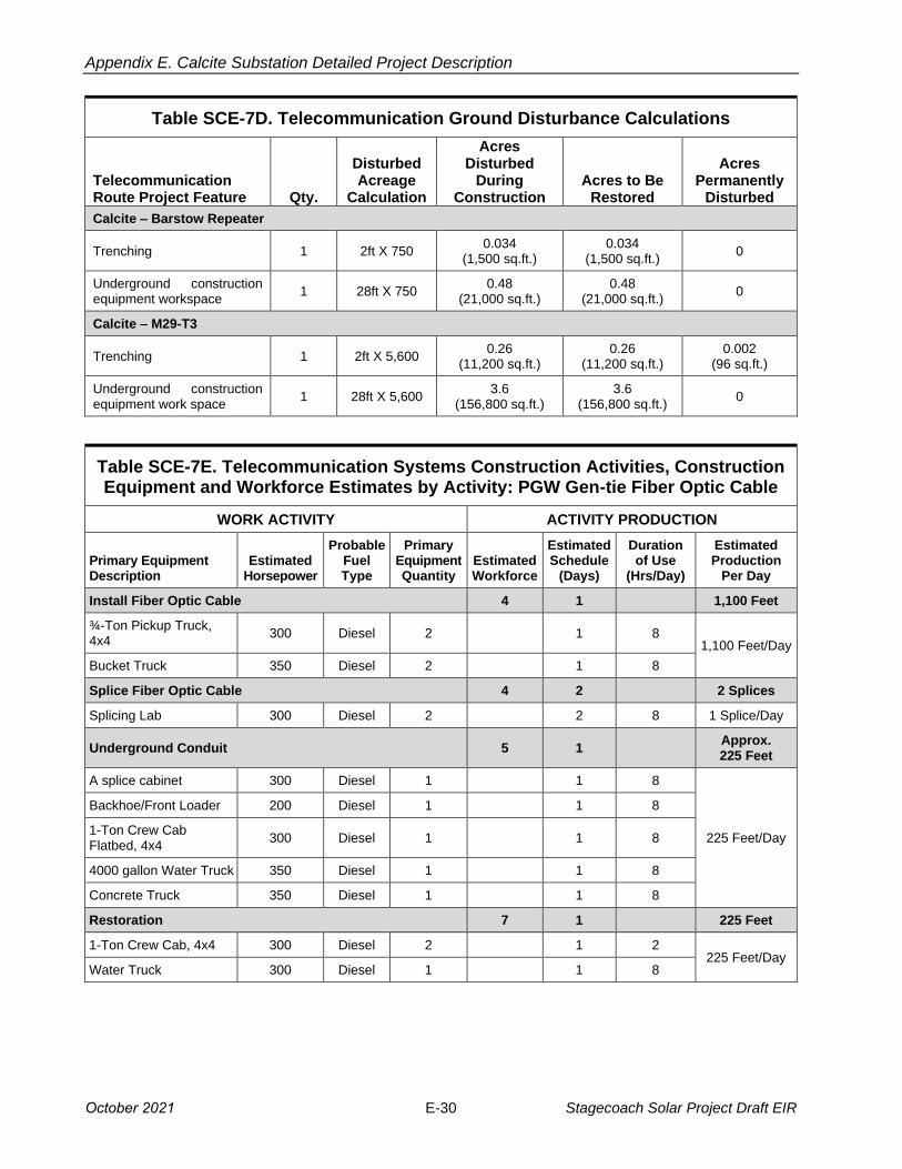
Appendix E. Calcite Substation Detailed Project Description
Table SCE-7D. Telecommunication Ground Disturbance Calculations
Telecommunication Route Project Feature Qty.
Disturbed Acreage
Calculation
Acres Disturbed
During Construction
Acres to Be Restored
Acres Permanently
Disturbed
Calcite – Barstow Repeater
Trenching 1 2ft X 750 0.034
(1,500 sq.ft.) 0.034
(1,500 sq.ft.) 0
Underground construction equipment workspace
1 28ft X 750 0.48
(21,000 sq.ft.) 0.48
(21,000 sq.ft.) 0
Calcite – M29-T3
Trenching 1 2ft X 5,600 0.26
(11,200 sq.ft.) 0.26
(11,200 sq.ft.) 0.002
(96 sq.ft.)
Underground construction equipment work space
1 28ft X 5,600 3.6
(156,800 sq.ft.) 3.6
(156,800 sq.ft.) 0
Table SCE-7E. Telecommunication Systems Construction Activities, Construction Equipment and Workforce Estimates by Activity: PGW Gen-tie Fiber Optic Cable
WORK ACTIVITY ACTIVITY PRODUCTION
Primary Equipment Description
Estimated Horsepower
Probable Fuel Type
Primary Equipment Quantity
Estimated Workforce
Estimated Schedule
(Days)
Duration of Use
(Hrs/Day)
Estimated Production
Per Day
Install Fiber Optic Cable 4 1 1,100 Feet
¾-Ton Pickup Truck, 4x4
300 Diesel 2 1 8 1,100 Feet/Day
Bucket Truck 350 Diesel 2 1 8
Splice Fiber Optic Cable 4 2 2 Splices
Splicing Lab 300 Diesel 2 2 8 1 Splice/Day
Underground Conduit 5 1 Approx. 225 Feet
A splice cabinet 300 Diesel 1 1 8
225 Feet/Day
Backhoe/Front Loader 200 Diesel 1 1 8
1-Ton Crew CabFlatbed, 4x4
300 Diesel 1 1 8
4000 gallon Water Truck 350 Diesel 1 1 8
Concrete Truck 350 Diesel 1 1 8
Restoration 7 1 225 Feet
1-Ton Crew Cab, 4x4 300 Diesel 2 1 2 225 Feet/Day
Water Truck 300 Diesel 1 1 8
October 2021 E-30 Stagecoach Solar Project Draft EIR

Appendix E. Calcite Substation Detailed Project Description
Table SCE-7F. Telecommunication Systems Construction Activities, Construction Equipment and Workforce Estimates by Activity: Redundant Gen-tie Fiber Optic
Cable
WORK ACTIVITY ACTIVITY PRODUCTION
Primary Equipment Description
Estimated Horsepower
Probable Fuel Type
Primary Equipment Quantity
Estimated Workforce
Estimated Schedule
(Days)
Duration of Use
(Hrs/Day)
Estimated Production
Per Day
Install Fiber Optic Cable 4 1 1,000 Feet
A splice cabinet Truck, 4x4
300 Diesel 2 1 8 1,000
Feet/Day Bucket Truck 350 Diesel 2 1 8
Splice Fiber Optic Cable 4 2 2 Splices
Splicing Lab 300 Diesel 2 2 2 8 1 Splices/Day
Underground Conduit 5 1 Approx. 225 Feet
A splice cabinet 300 Diesel 1 1 8
225 Feet/Day
Backhoe/Front Loader 200 Diesel 1 1 8
1-Ton Crew Cab Flatbed,4x4
300 Diesel 1 1 8
4000 gallon Water Truck 350 Diesel 1 1 8
Concrete Truck 350 Diesel 1 1 8
Restoration 7 1 225 Feet
1-Ton Crew Cab, 4x4 300 Diesel 2 1 2 225 Feet/Day
Water Truck 300 Diesel 1 1 8
Table SCE-7G. Telecommunication Fiber Optic Gen-tie Cable Summary
OPGW Gen-tie ADSS Gen-tie
Fiber-Optic Cable Length (Proposed) 1,100 Feet 1,000 Feet
Total Length Underground (U.G.) 1,100 Feet 1,000 Feet
Existing U.G. Conduits (Installed by Substation Construction) 875 Feet 775 Feet
New U.G. Conduits Needed 225Feet 225 Feet
Total Length Overhead (O.H.) 0 Feet 0 Feet
On Existing Poles – O.H. 0 Feet 0 Feet
On New Poles – O.H. 0 Feet 0 Feet
Existing Poles 0 0
New Poles Required 0 0
New Down Guys Required 0 0
Time and Resources to Construct (4 men per crew) 5 Crew Days 5 Crew Days
Total Man Days Required 20 Man Days 20 Man Days
Stagecoach Solar Project E-31 October 2021
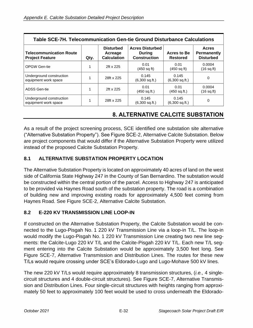
Appendix E. Calcite Substation Detailed Project Description
Table SCE-7H. Telecommunication Gen-tie Ground Disturbance Calculations
Telecommunication Route Project Feature Qty.
Disturbed Acreage
Calculation
Acres Disturbed During
Construction Acres to Be
Restored
Acres Permanently
Disturbed
OPGW Gen-tie 1 2ft x 225 0.01
(450 sq ft) 0.01
(450 sq ft) 0.0004
(16 sq.ft)
Underground construction equipment work space
1 28ft x 225 0.145
(6,300 sq.ft.) 0.145
(6,300 sq.ft.) 0
ADSS Gen-tie 1 2ft x 225 0.01
(450 sq.ft.) 0.01
(450 sq.ft.) 0.0004
(16 sq.ft)
Underground construction equipment work space
1 28ft x 225 0.145
(6,300 sq.ft.) 0.145
(6,300 sq.ft.) 0
8. ALTERNATIVE CALCITE SUBSTATION
As a result of the project screening process, SCE identified one substation site alternative
(“Alternative Substation Property”). See Figure SCE-2, Alternative Calcite Substation. Below
are project components that would differ if the Alternative Substation Property were utilized
instead of the proposed Calcite Substation Property.
8.1 ALTERNATIVE SUBSTATION PROPERTY LOCATION
The Alternative Substation Property is located on approximately 40 acres of land on the west
side of California State Highway 247 in the County of San Bernardino. The substation would
be constructed within the central portion of the parcel. Access to Highway 247 is anticipated
to be provided via Haynes Road south of the substation property. The road is a combination
of building new and improving existing roads for approximately 4,500 feet coming from
Haynes Road. See Figure SCE-2, Alternative Calcite Substation.
8.2 E-220 KV TRANSMISSION LINE LOOP-IN
If constructed on the Alternative Substation Property, the Calcite Substation would be con
nected to the Lugo-Pisgah No. 1 220 kV Transmission Line via a loop-in T/L. The loop-in
would modify the Lugo-Pisgah No. 1 220 kV Transmission Line creating two new line seg
ments: the Calcite-Lugo 220 kV T/L and the Calcite-Pisgah 220 kV T/L. Each new T/L seg
ment entering into the Calcite Substation would be approximately 3,500 feet long. See
Figure SCE-7, Alternative Transmission and Distribution Lines. The routes for these new
T/Ls would require crossing under SCE’s Eldorado-Lugo and Lugo-Mohave 500 kV lines.
The new 220 kV T/Ls would require approximately 8 transmission structures, (i.e., 4 single-
circuit structures and 4 double-circuit structures). See Figure SCE-7, Alternative Transmis
sion and Distribution Lines. Four single-circuit structures with heights ranging from approxi
mately 50 feet to approximately 100 feet would be used to cross underneath the Eldorado-
October 2021 E-32 Stagecoach Solar Project Draft EIR
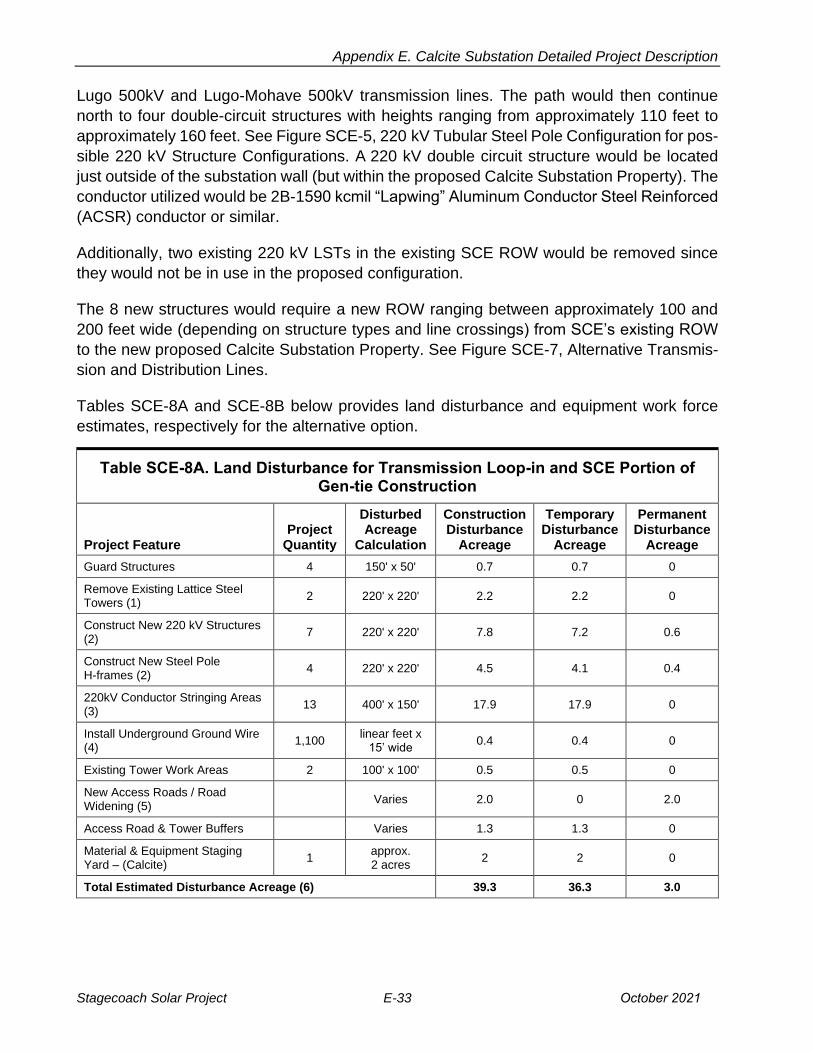
Appendix E. Calcite Substation Detailed Project Description
Lugo 500kV and Lugo-Mohave 500kV transmission lines. The path would then continue
north to four double-circuit structures with heights ranging from approximately 110 feet to
approximately 160 feet. See Figure SCE-5, 220 kV Tubular Steel Pole Configuration for pos
sible 220 kV Structure Configurations. A 220 kV double circuit structure would be located
just outside of the substation wall (but within the proposed Calcite Substation Property). The
conductor utilized would be 2B-1590 kcmil “Lapwing” Aluminum Conductor Steel Reinforced (ACSR) conductor or similar.
Additionally, two existing 220 kV LSTs in the existing SCE ROW would be removed since
they would not be in use in the proposed configuration.
The 8 new structures would require a new ROW ranging between approximately 100 and
200 feet wide (depending on structure types and line crossings) from SCE’s existing ROW
to the new proposed Calcite Substation Property. See Figure SCE-7, Alternative Transmis
sion and Distribution Lines.
Tables SCE-8A and SCE-8B below provides land disturbance and equipment work force
estimates, respectively for the alternative option.
Table SCE-8A. Land Disturbance for Transmission Loop-in and SCE Portion of Gen-tie Construction
Project Feature Project
Quantity
Disturbed Acreage
Calculation
Construction Disturbance
Acreage
Temporary Disturbance
Acreage
Permanent Disturbance
Acreage
Guard Structures 4 150' x 50' 0.7 0.7 0
Remove Existing Lattice Steel Towers (1)
2 220' x 220' 2.2 2.2 0
Construct New 220 kV Structures (2)
7 220' x 220' 7.8 7.2 0.6
Construct New Steel Pole H-frames (2)
4 220' x 220' 4.5 4.1 0.4
220kV Conductor Stringing Areas (3)
13 400' x 150' 17.9 17.9 0
Install Underground Ground Wire (4)
1,100 linear feet x 15’ wide
0.4 0.4 0
Existing Tower Work Areas 2 100' x 100' 0.5 0.5 0
New Access Roads / Road Widening (5)
Varies 2.0 0 2.0
Access Road & Tower Buffers Varies 1.3 1.3 0
Material & Equipment Staging Yard – (Calcite)
1 approx. 2 acres
2 2 0
Total Estimated Disturbance Acreage (6) 39.3 36.3 3.0
Stagecoach Solar Project E-33 October 2021

Appendix E. Calcite Substation Detailed Project Description
1 - Includes the removal of existing conductor, teardown of existing structure, and removal of foundation 2' below ground surface.
2 - Includes structure assembly & erection, conductor & OHGW installation. Area to be restored after construction. Portion of R/W within 20' of ALL structures to remain cleared of vegetation. Permanently disturbed areas for HFrame/3 Pole=0.08 acre.
3 - Based on standard conductor reel lengths, conductor size, number of circuits, route design, and terrain. 4 - Based on a required ground wire needed between structures underneath the existing 500kV T/Ls. 5 - Based on a combination of widening existing roads and constructing new roads to a drivable road width of 14' 22' w/ 2'
of berm on each side of road. 6 - The disturbed acreage calculations are estimates based upon SCE’s preferred area of use for the described project
feature, the width of the existing right-of-way, or the width of the proposed right-of-way. They are subject to revision based upon final engineering and review of the project by SCE's Construction Manager and/or Contractor awarded project.
Foundation / Base Volume and Area Calculations (approximate):
H-Frame: 2 per structure, 30-ft deep, 6-ft diameter; Earth removed for footings = 62.8 cu.yd; Surface area = 56.5 sq.ft.
Table SCE-8B. Calcite Substation Project Construction, Equipment and Workforce Estimates by Activity: Construct 220 kV Transmission Line Loop-in and Gen-tie
WORK ACTIVITY ACTIVITY ESTIMATES
Primary Equipment Description
Estimated Horsepower
Probable Fuel Type
Primary Equipment
Quantity
Estimated Crew
Workforce
Estimated Schedule
(Days)
Estimated Usage
(Hrs/Day)
Estimated Activity Value
Survey (1) 4 4 4 Miles
1-Ton Truck, 4x4 300 Gas 2 4 8 1 Mile
Staging/Material Yard (2) 4 1 Yard
1-Ton Truck, 4x4 300 Gas 2
Duration of Project
4
R/T Forklift 125 Diesel 1 4
Ranger 50 Diesel 1 4
Generator 49 Diesel 1 8
Water Truck 300 Diesel 2 8
Road Work & Structure Pads (3) 5 11 2 Miles & 11 Pads
1-Ton Truck, 4x4 300 Gas 1 11 8
Backhoe/Front Loader
125 Diesel 1 11 4
Tracked Dozer 150 Diesel 1 11 8
Motor Grader 250 Diesel 1 11 8
Water Truck 300 Diesel 2 11 8
Drum Compactor 100 Diesel 1 11 4
Excavator 250 Diesel 1 3 4
Lowboy Truck/Trailer 450 Diesel 1 11 2
Guard Structure Installation (4) 6 2 4
Structures
1-Ton Truck, 4x4 300 Gas 2 2 8
Compressor Trailer 60 Diesel 1 2 4
Manlift/Bucket Truck 250 Diesel 1 2 4
Boom/Crane Truck 350 Diesel 1 2 8
Auger Truck 210 Diesel 1 2 4
October 2021 E-34 Stagecoach Solar Project Draft EIR

Appendix E. Calcite Substation Detailed Project Description
Table SCE-8B. Calcite Substation Project Construction, Equipment and Workforce Estimates by Activity: Construct 220 kV Transmission Line Loop-in and Gen-tie
WORK ACTIVITY ACTIVITY ESTIMATES
Primary Equipment Description
Estimated Horsepower
Probable Fuel Type
Primary Equipment
Quantity
Estimated Crew
Workforce
Estimated Schedule
(Days)
Estimated Usage
(Hrs/Day)
Estimated Activity Value
Flatbed Truck 400 Diesel 1 2 8
Conductor & GW Removal (5) 14 4 9,250 Feet
1-Ton Truck, 4x4 300 Gas 4 4 4
Manlift/Bucket Truck 250 Diesel 2 4 8
Boom/Crane Truck 350 Diesel 2 4 8
Puller 350 Diesel 1 4 8
Static Truck/ Tensioner
350 Diesel 1 4 8
Dump/Stake Bed Truck
350 Diesel 1 4 8
LST Removal (6) 6 4 2
Structures
1-Ton Truck, 4x4 300 Gas 2 4 4
Compressor Trailer 60 Diesel 1 4 8
R/T Crane (L) 275 Diesel 1 4 8
Dump Truck 350 Diesel 1 4 8
Flatbed Truck 400 Diesel 1 4 2
LST Foundation Removal (7) 4 2 2
Structures
1-Ton Truck, 4x4 300 Gas 2 2 4
Compressor Trailer 60 Diesel 1 2 8
Backhoe/Front Loader
125 Diesel 1 2 8
Dump Truck 350 Diesel 1 2 8
Excavator 250 Diesel 1 2 2
220 kV Structure Foundation Installation (8) 6 19 11
Structures
1-Ton Truck, 4x4 300 Gas 2 19 4
Boom/Crane Truck 350 Diesel 1 19 4
Backhoe/Front Loader
125 Diesel 1 19 8
Drill Rig 275 Diesel 1 12 8
Water Truck 300 Diesel 1 19 8
Dump Truck 350 Diesel 1 19 8
Concrete Truck 350 Diesel 3 10 6
220 kV Structure Steel Haul (9) 4 4 11
Structures
1-Ton Truck, 4x4 300 Gas 1 4 8
Boom/Crane Truck 350 Diesel 1 4 4
Flatbed Truck 400 Diesel 1 4 8
Stagecoach Solar Project E-35 October 2021
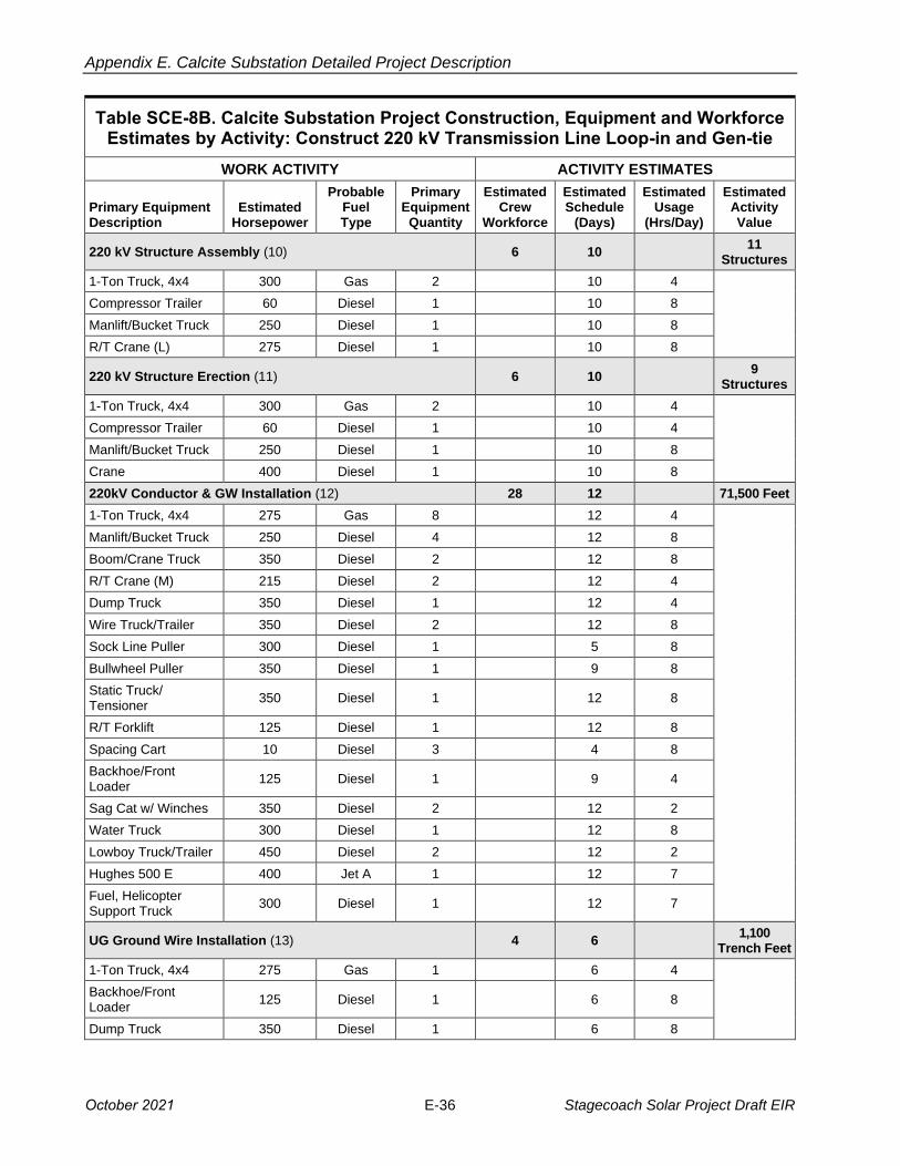
Appendix E. Calcite Substation Detailed Project Description
Table SCE-8B. Calcite Substation Project Construction, Equipment and Workforce Estimates by Activity: Construct 220 kV Transmission Line Loop-in and Gen-tie
WORK ACTIVITY ACTIVITY ESTIMATES
Primary Equipment Description
Estimated Horsepower
Probable Fuel Type
Primary Equipment
Quantity
Estimated Crew
Workforce
Estimated Schedule
(Days)
Estimated Usage
(Hrs/Day)
Estimated Activity Value
220 kV Structure Assembly (10) 6 10 11
Structures
1-Ton Truck, 4x4 300 Gas 2 10 4
Compressor Trailer 60 Diesel 1 10 8
Manlift/Bucket Truck 250 Diesel 1 10 8
R/T Crane (L) 275 Diesel 1 10 8
220 kV Structure Erection (11) 6 10 9
Structures
1-Ton Truck, 4x4 300 Gas 2 10 4
Compressor Trailer 60 Diesel 1 10 4
Manlift/Bucket Truck 250 Diesel 1 10 8
Crane 400 Diesel 1 10 8
220kV Conductor & GW Installation (12) 28 12 71,500 Feet
1-Ton Truck, 4x4 275 Gas 8 12 4
Manlift/Bucket Truck 250 Diesel 4 12 8
Boom/Crane Truck 350 Diesel 2 12 8
R/T Crane (M) 215 Diesel 2 12 4
Dump Truck 350 Diesel 1 12 4
Wire Truck/Trailer 350 Diesel 2 12 8
Sock Line Puller 300 Diesel 1 5 8
Bullwheel Puller 350 Diesel 1 9 8
Static Truck/ Tensioner
350 Diesel 1 12 8
R/T Forklift 125 Diesel 1 12 8
Spacing Cart 10 Diesel 3 4 8
Backhoe/Front Loader
125 Diesel 1 9 4
Sag Cat w/ Winches 350 Diesel 2 12 2
Water Truck 300 Diesel 1 12 8
Lowboy Truck/Trailer 450 Diesel 2 12 2
Hughes 500 E 400 Jet A 1 12 7
Fuel, Helicopter Support Truck
300 Diesel 1 12 7
UG Ground Wire Installation (13) 4 6 1,100
Trench Feet
1-Ton Truck, 4x4 275 Gas 1 6 4
Backhoe/Front Loader
125 Diesel 1 6 8
Dump Truck 350 Diesel 1 6 8
October 2021 E-36 Stagecoach Solar Project Draft EIR
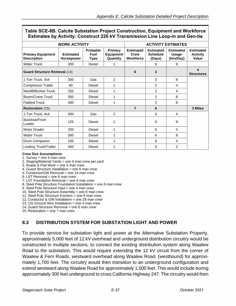
Appendix E. Calcite Substation Detailed Project Description
Table SCE-8B. Calcite Substation Project Construction, Equipment and Workforce Estimates by Activity: Construct 220 kV Transmission Line Loop-in and Gen-tie
WORK ACTIVITY ACTIVITY ESTIMATES
Primary Equipment Description
Estimated Horsepower
Probable Fuel Type
Primary Equipment
Quantity
Estimated Crew
Workforce
Estimated Schedule
(Days)
Estimated Usage
(Hrs/Day)
Estimated Activity Value
Water Truck 300 Diesel 1 6 8
Guard Structure Removal (14) 6 2 4
Structures
1-Ton Truck, 4x4 300 Gas 2 2 8
Compressor Trailer 60 Diesel 1 2 4
Manlift/Bucket Truck 250 Diesel 1 2 4
Boom/Crane Truck 350 Diesel 1 2 8
Flatbed Truck 400 Diesel 1 2 8
Restoration (15) 7 6 3 Miles
1-Ton Truck, 4x4 300 Gas 2 6 4
Backhoe/Front Loader
125 Diesel 1 6 8
Motor Grader 250 Diesel 1 6 4
Water Truck 300 Diesel 1 6 8
Drum Compactor 100 Diesel 1 6 4
Lowboy Truck/Trailer 450 Diesel 1 6 2
Crew Size Assumptions: 1. Survey = one 4 man crew2. Staging/Material Yards = one 4 man crew per yard3. Roads & Pad Work = one 5 man crew4. Guard Structure Installation = one 6 man crew5. Conductor/GW Removal = one 14 man crew6. LST Removal = one 6 man crew7. LST Foundation Removal = one 4 man crew8. Steel Pole Structure Foundation Installation = one 6 man crew9. Steel Pole Structure Haul = one 4 man crew10. Steel Pole Structure Assembly = one 6 man crew11. Steel Pole Structure Erection = one 6 man crew12. Conductor & GW Installation = one 28 man crew13. UG Ground Wire Installation = one 4 man crew14. Guard Structure Removal = one 6 man crew15. Restoration = one 7 man crew
8.3 DISTRIBUTION SYSTEM FOR SUBSTATION LIGHT AND POWER
To provide service for substation light and power at the Alternative Substation Property,
approximately 5,000 feet of 12 kV overhead and underground distribution circuitry would be
constructed in multiple sections, to connect the existing distribution system along Waalew
Road to the substation. This would require extending the 12 kV circuit from the corner of
Waalew & Fern Roads, westward overhead along Waalew Road, (westbound) for approxi
mately 1,700 feet. The circuitry would then transition to an underground configuration and
extend westward along Waalew Road for approximately 1,500 feet. This would include boring
approximately 300 feet underground to cross California Highway 247. The circuitry would then
Stagecoach Solar Project E-37 October 2021
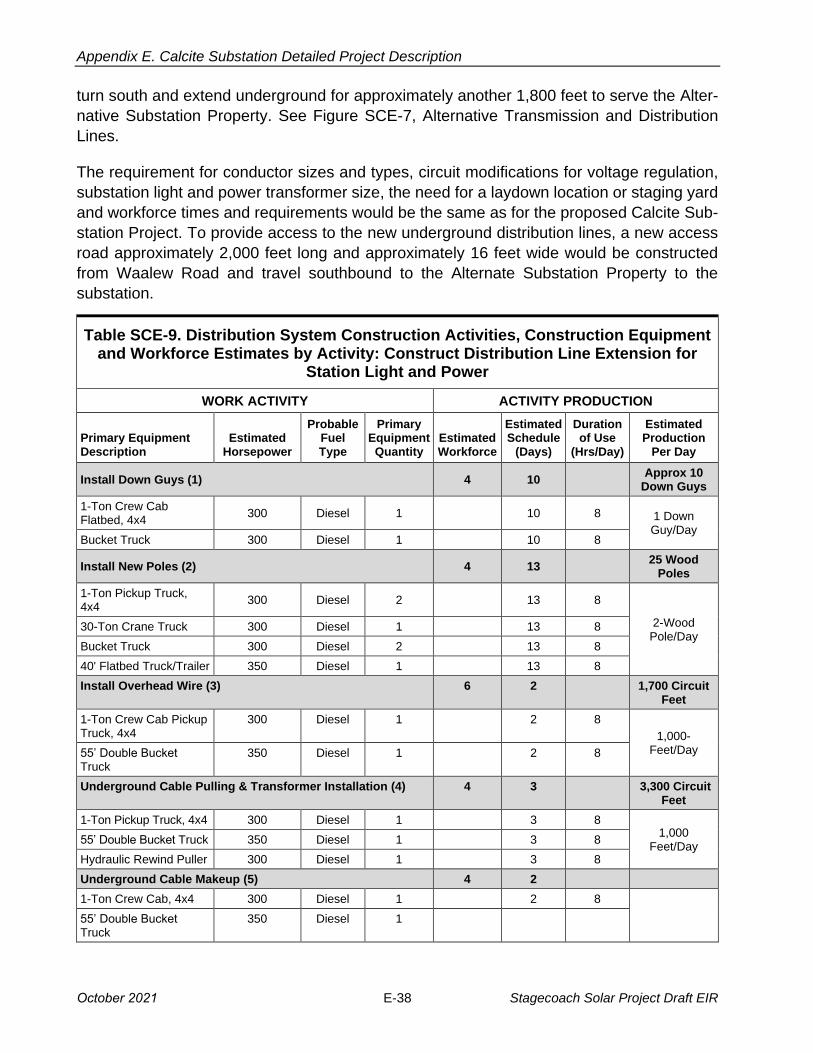
Appendix E. Calcite Substation Detailed Project Description
turn south and extend underground for approximately another 1,800 feet to serve the Alter
native Substation Property. See Figure SCE-7, Alternative Transmission and Distribution
Lines.
The requirement for conductor sizes and types, circuit modifications for voltage regulation,
substation light and power transformer size, the need for a laydown location or staging yard
and workforce times and requirements would be the same as for the proposed Calcite Sub
station Project. To provide access to the new underground distribution lines, a new access
road approximately 2,000 feet long and approximately 16 feet wide would be constructed
from Waalew Road and travel southbound to the Alternate Substation Property to the
substation.
Table SCE-9. Distribution System Construction Activities, Construction Equipment and Workforce Estimates by Activity: Construct Distribution Line Extension for
Station Light and Power
WORK ACTIVITY ACTIVITY PRODUCTION
Primary Equipment Description
Estimated Horsepower
Probable Fuel Type
Primary Equipment
Quantity Estimated Workforce
Estimated Schedule
(Days)
Duration of Use
(Hrs/Day)
Estimated Production
Per Day
Install Down Guys (1) 4 10 Approx 10
Down Guys
1-Ton Crew CabFlatbed, 4x4
300 Diesel 1 10 8 1 Down Guy/Day
Bucket Truck 300 Diesel 1 10 8
Install New Poles (2) 4 13 25 Wood
Poles
1-Ton Pickup Truck,4x4
300 Diesel 2 13 8
2-WoodPole/Day
30-Ton Crane Truck 300 Diesel 1 13 8
Bucket Truck 300 Diesel 2 13 8
40' Flatbed Truck/Trailer 350 Diesel 1 13 8
Install Overhead Wire (3) 6 2 1,700 Circuit Feet
1-Ton Crew Cab PickupTruck, 4x4
300 Diesel 1 2 8
1,000Feet/Day 55’ Double Bucket
Truck 350 Diesel 1 2 8
Underground Cable Pulling & Transformer Installation (4) 4 3 3,300 Circuit Feet
1-Ton Pickup Truck, 4x4 300 Diesel 1 3 8 1,000
Feet/Day 55’ Double Bucket Truck 350 Diesel 1 3 8
Hydraulic Rewind Puller 300 Diesel 1 3 8
Underground Cable Makeup (5) 4 2
1-Ton Crew Cab, 4x4 300 Diesel 1 2 8
55’ Double Bucket Truck
350 Diesel 1
October 2021 E-38 Stagecoach Solar Project Draft EIR

Appendix E. Calcite Substation Detailed Project Description
Table SCE-9. Distribution System Construction Activities, Construction Equipment and Workforce Estimates by Activity: Construct Distribution Line Extension for
Station Light and Power
WORK ACTIVITY ACTIVITY PRODUCTION
Primary Equipment Description
Estimated Horsepower
Probable Fuel Type
Primary Equipment
Quantity Estimated Workforce
Estimated Schedule
(Days)
Duration of Use
(Hrs/Day)
Estimated Production
Per Day
Underground Trenching/Structure Excavation Conduit (6) 4 7 Approx. 3,300 Feet
1-Ton Pick-up Truck,4x4
300 Diesel 1 7 8
500 Feet/Day
Backhoe/Front Loader 200 Diesel 1 7 8
1-Ton Crew CabFlatbed, 4x4
300 Diesel 1 7 8
4000 gallon Water Truck
350 Diesel 1 7 8
Concrete Truck 350 Diesel 1 7 8
Survey (7) 4 1 0.5 Miles
1 Ton Truck, 4x4 300 Gas 2 4 1 8 1 Mile/Day
Road Work (8) 5 3 0.5 Miles
1 Ton Truck, 4x4 300 Gas 1 3 8
800 Feet/Day
Backhoe/Front Loader
200 Diesel 1 3 4
Tracked Dozer 150 Diesel 1 3 8
Motor Grader 250 Diesel 1 3 8
Water Truck 300 Diesel 2 3 8
Drum Compactor 100 Diesel 1 3 4
Excavator 250 Diesel 1 3 4
Lowboy Truck/Trailer 450 Diesel 1 3 2
Underground Boring, Casing and Conduit Installation (9)
6 3 Approx. 300 Feet
1-Ton Pick-up Truck,4x4
300 Diesel 1 3 8
100 Feet/Day
Backhoe/Front Loader
200 Diesel 1 3 8
1-Ton Crew CabFlatbed, 4x4
300 Diesel 1 3 8
Excavation and Boring Equipment
300 Diesel 1 3 8
Restoration (10) 4 1 3,300 Feet
1-Ton Crew Cab, 4x4 300 Diesel 2 1 2 1 Mile/Day
Water Truck 300 Diesel 1 1 8
Stagecoach Solar Project E-39 October 2021

Appendix E. Calcite Substation Detailed Project Description
Distribution Land Disturbance
Project Feature Project
Quantity
Disturbed Acreage
Calculation
Construction Disturbance
Acreage
Temporary Disturbance
Acreage
Acres Permanently
Disturbed
Underground trench/duct for conduit
1 3,300 ft. x 2 ft. 0.151 0.151 0
Underground construction equipment work space
1 3,300 ft. x 28 ft. 2.121 2.121 0
Distribution line excavation pits
10 10 ft. x 24 ft. 0.055 0.055 0
Underground Highway crossing
1 No surface disturbance
No surface disturbance
No surface disturbance
No surface disturbance
Distribution line vault covers
8 4 ft. x 5 ft. 0.0036 0 0.0036
New Poles 25 2.5 ft. diameter
(5.0 sq.ft.) 0.0028 0 0.0028
Down Guys 10 1 ft. x 1.25 ft. 0.0002 0 0.0002
Overhead construction equipment work space
5 125 ft. x 60 ft. 0.86 0.86 0
Distribution access road 1 16 ft. x 2000 ft. 0.734 0.092 0.642
Total Estimated Disturbance Acreage 3.928 3.279 0.6486
Distribution System for Station Light & Power
Distribution Circuit Extension Length (Proposed) 5000 ft. (0.95 miles)
Total Length Underground (U.G.) 3,300 ft.
New U.G. Conduits Needed 3,300 ft
Total Length Overhead (O.H.) 1,700 ft.
New Poles – O.H. 1,700 ft.
New Poles Required 25
New Down Guys Required 10
New Distribution Access Road 2,000 ft. x 16 ft.
Time and Resources to Construct (Approximately 4 men per crew) 45 Crew Days
Total Man Days Required 180 Man Days
Crew Size Assumptions: 1. Overhead Line Work = one 3 man crew2. Pole Installation/Replacement crew = one 4 man crew3. Overhead Line Work = two 3 man crews4. Underground Cable Pulling = one 4 man crew5. Underground Cable Makeup = one 4 man crew6. Trenching and Conduit Installation = one 4 man crew7. Survey = one 4 man crew8. Road Work = one 5 man crew9. Trenching and Underground Boring = one 6 man crew10. Trenching Backfill and Restoration = one 4 man crew
October 2021 E-40 Stagecoach Solar Project Draft EIR
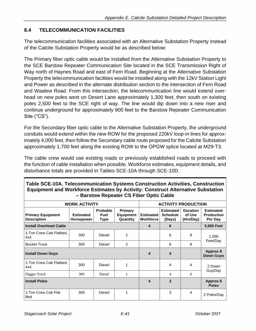
Appendix E. Calcite Substation Detailed Project Description
8.4 TELECOMMUNICATION FACILITIES
The telecommunication facilities associated with an Alternative Substation Property instead
of the Calcite Substation Property would be as described below:
The Primary fiber optic cable would be installed from the Alternative Substation Property to
the SCE Barstow Repeater Communication Site located in the SCE Transmission Right of
Way north of Haynes Road and east of Fern Road. Beginning at the Alternative Substation
Property the telecommunication facilities would be installed along with the 12kV Station Light
and Power as described in the alternate distribution section to the intersection of Fern Road
and Waalew Road. From this intersection, the telecommunication line would extend over
head on new poles west on Desert Lane approximately 1,300 feet, then south on existing
poles 2,500 feet to the SCE right of way. The line would dip down into a new riser and
continue underground for approximately 900 feet to the Barstow Repeater Communication
Site (“CS”).
For the Secondary fiber optic cable to the Alternative Substation Property, the underground
conduits would extend within the new ROW for the proposed 220kV loop-in lines for approx
imately 4,000 feet, then follow the Secondary cable route proposed for the Calcite Substation
approximately 1,700 feet along the existing ROW to the OPGW splice located at M29-T3.
The cable crew would use existing roads or previously established roads to proceed with
the function of cable installation when possible. Workforce estimates, equipment details, and
disturbance totals are provided in Tables SCE-10A through SCE-10D.
Table SCE-10A. Telecommunication Systems Construction Activities, Construction Equipment and Workforce Estimates by Activity: Construct Alternative Substation
– Barstow Repeater CS Fiber Optic Cable
WORK ACTIVITY ACTIVITY PRODUCTION
Primary Equipment Description
Estimated Horsepower
Probable Fuel Type
Primary Equipment Quantity
Estimated Workforce
Estimated Schedule
(Days)
Duration of Use
(Hrs/Day)
Estimated Production
Per Day
Install Overhead Cable 4 6 5,500 Feet
1-Ton Crew Cab Flatbed,4x4
300 Diesel 1 6 8 1,000 Feet/Day
Bucket Truck 300 Diesel 2 6 8
Install Down Guys 4 4 Approx 8
Down Guys
1-Ton Crew Cab Flatbed,4x4
300 Diesel 1 4 4 2 Down Guy/Day
Digger Truck 300 Diesel 1 4 6
Install Poles 4 3 Approx 6 Poles
1-Ton Crew Cab FlatBed
300 Diesel 1 3 4 2 Poles/Day
Stagecoach Solar Project E-41 October 2021

Appendix E. Calcite Substation Detailed Project Description
Table SCE-10A. Telecommunication Systems Construction Activities, Construction Equipment and Workforce Estimates by Activity: Construct Alternative Substation
– Barstow Repeater CS Fiber Optic Cable
WORK ACTIVITY ACTIVITY PRODUCTION
Primary Equipment Description
Estimated Horsepower
Probable Fuel Type
Primary Equipment Quantity
Estimated Workforce
Estimated Schedule
(Days)
Duration of Use
(Hrs/Day)
Estimated Production
Per Day
Digger Truck 300 Diesel 1 3 6
Install Underground Fiber Optic Cable 8 4 4,200 Feet
¾-Ton Pick-up Truck, 4x4
300 Diesel 2 4 8 1,000 Feet/Day
Bucket Truck 350 Diesel 2 4 8
Splice Fiber Optic Cable 4 4 4 Splices
Splicing Lab 300 Diesel 2 4 4 1 Splice/Day
Underground Conduit at Repeater Site 5 2 Approx. 900 Feet
¾-Ton Pick-up Truck, 4x4 300 Diesel 1 2 8
500 Feet/Day
Backhoe/Front Loader 200 Diesel 1 2 8
1-Ton Crew Cab Flatbed,4x4
300 Diesel 1 2 8
4000 gallon Water Truck 350 Diesel 1 2 8
Concrete Truck 350 Diesel 1 2 4
Restoration 7 1 900 Feet
1-Ton Crew Cab, 4x4 300 Diesel 2 1 8 900/Day
Water Truck 300 Diesel 1 1 8
Table SCE-10B. Telecommunication Systems Construction Activities, Construction Equipment and Workforce Estimates by Activity: Construct Alternative Substation
to OPGW splice at M29-T3 Fiber Optic Cable
WORK ACTIVITY ACTIVITY PRODUCTION
Primary Equipment Description
Estimated Horsepower
Probable Fuel Type
Primary Equipment Quantity
Estimated Workforce
Estimated Schedule
(Days)
Duration of Use
(Hrs/Day)
Estimated Production
Per Day
Install Fiber Optic Cable (3) 8 6 5,700 Feet
¾-Ton Pick-up Truck, 4x4 300 Diesel 2 6 8 2,000 Feet/Day Bucket Truck 350 Diesel 2 6 8
Splice Fiber Optic Cable 4 4 4 Splices
Splicing Lab 300 Diesel 2 8 4 1 Splice/Day
Underground Conduit 5 12 Approx.
5,700 Feet
¾-Ton Pick-up Truck, 4x4 300 Diesel 1 12 8 500 Feet/Day
October 2021 E-42 Stagecoach Solar Project Draft EIR
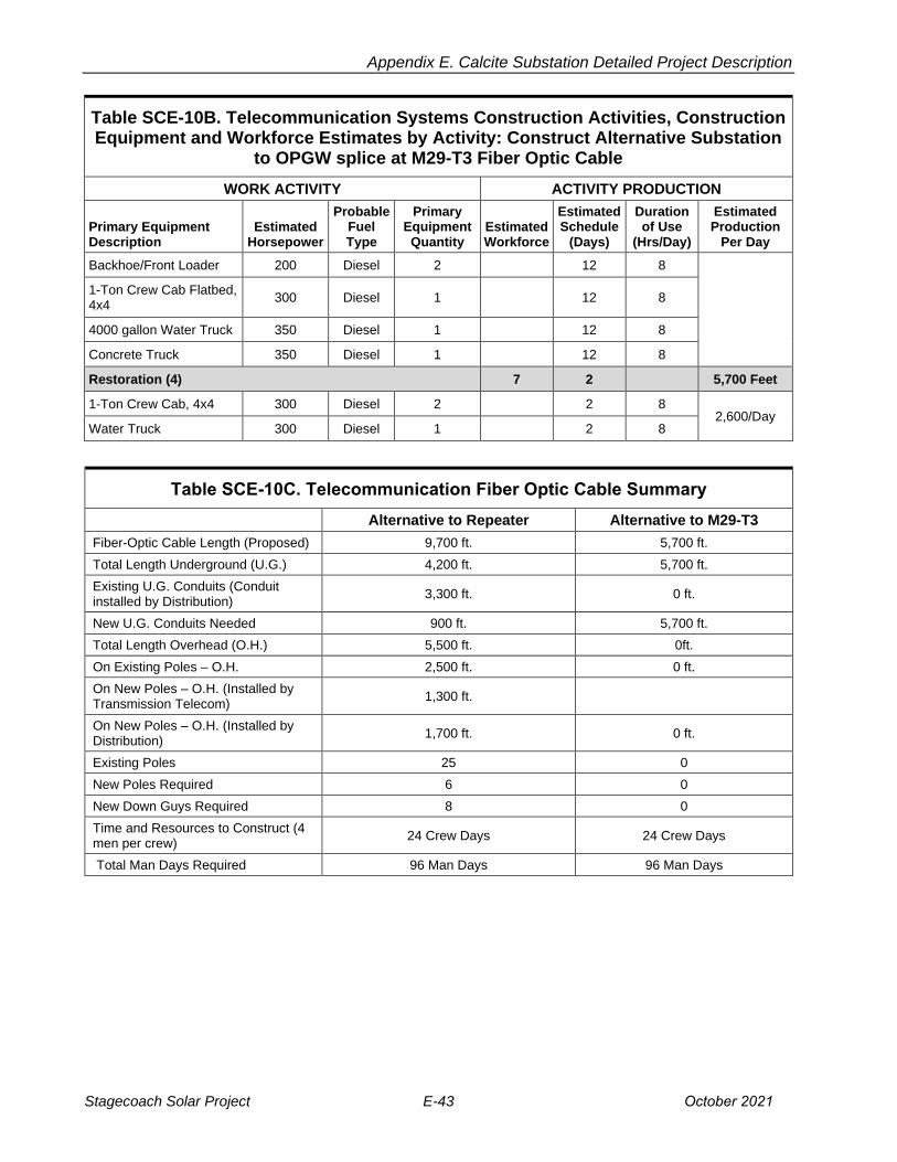
Appendix E. Calcite Substation Detailed Project Description
Table SCE-10B. Telecommunication Systems Construction Activities, Construction Equipment and Workforce Estimates by Activity: Construct Alternative Substation
to OPGW splice at M29-T3 Fiber Optic Cable
WORK ACTIVITY ACTIVITY PRODUCTION
Primary Equipment Description
Estimated Horsepower
Probable Fuel Type
Primary Equipment Quantity
Estimated Workforce
Estimated Schedule
(Days)
Duration of Use
(Hrs/Day)
Estimated Production
Per Day
Backhoe/Front Loader 200 Diesel 2 12 8
1-Ton Crew Cab Flatbed,4x4
300 Diesel 1 12 8
4000 gallon Water Truck 350 Diesel 1 12 8
Concrete Truck 350 Diesel 1 12 8
Restoration (4) 7 2 5,700 Feet
1-Ton Crew Cab, 4x4 300 Diesel 2 2 8 2,600/Day
Water Truck 300 Diesel 1 2 8
Table SCE-10C. Telecommunication Fiber Optic Cable Summary
Alternative to Repeater Alternative to M29-T3
Fiber-Optic Cable Length (Proposed) 9,700 ft. 5,700 ft.
Total Length Underground (U.G.) 4,200 ft. 5,700 ft.
Existing U.G. Conduits (Conduit installed by Distribution)
3,300 ft. 0 ft.
New U.G. Conduits Needed 900 ft. 5,700 ft.
Total Length Overhead (O.H.) 5,500 ft. 0ft.
On Existing Poles – O.H. 2,500 ft. 0 ft.
On New Poles – O.H. (Installed by Transmission Telecom)
1,300 ft.
On New Poles – O.H. (Installed by Distribution)
1,700 ft. 0 ft.
Existing Poles 25 0
New Poles Required 6 0
New Down Guys Required 8 0
Time and Resources to Construct (4 men per crew)
24 Crew Days 24 Crew Days
Total Man Days Required 96 Man Days 96 Man Days
Stagecoach Solar Project E-43 October 2021
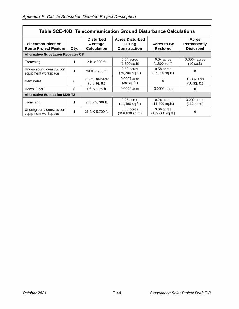
Appendix E. Calcite Substation Detailed Project Description
Table SCE-10D. Telecommunication Ground Disturbance Calculations
Telecommunication Route Project Feature Qty.
Disturbed Acreage
Calculation
Acres Disturbed During
Construction Acres to Be
Restored
Acres Permanently
Disturbed
Alternative Substation Repeater CS
Trenching 1 2 ft. x 900 ft. 0.04 acres
(1,800 sq.ft) 0.04 acres
(1,800 sq.ft) 0.0004 acres
(16 sq.ft)
Underground construction equipment workspace
1 28 ft. x 900 ft. 0.58 acres
(25,200 sq.ft.) 0.58 acres
(25,200 sq.ft.) 0
New Poles 6 2.5 ft. Diameter
(5.0 sq. ft.)
0.0007 acre (30 sq. ft.)
0 0.0007 acre (30 sq. ft.)
Down Guys 8 1 ft. x 1.25 ft. 0.0002 acre 0.0002 acre 0
Alternative Substation M29-T3
Trenching 1 2 ft. x 5,700 ft. 0.26 acres
(11,400 sq.ft.) 0.26 acres
(11,400 sq.ft.) 0.002 acres (112 sq.ft.)
Underground construction equipment workspace
1 28 ft X 5,700 ft. 3.66 acres
(159,600 sq.ft.) 3.66 acres
(159,600 sq.ft.) 0
October 2021 E-44 Stagecoach Solar Project Draft EIR
ATTACHMENT 1: FIGURES AND TABLES
This attachment includes the following:
• Table A: Total Construction Water Demand: Proposed Substation
• Table B: Total Construction Water Demand: Alternative Substation
• Figures SCE-1 through SCE-7 follow the two tables.
Stagecoach Solar Project Att1-1 October 2021
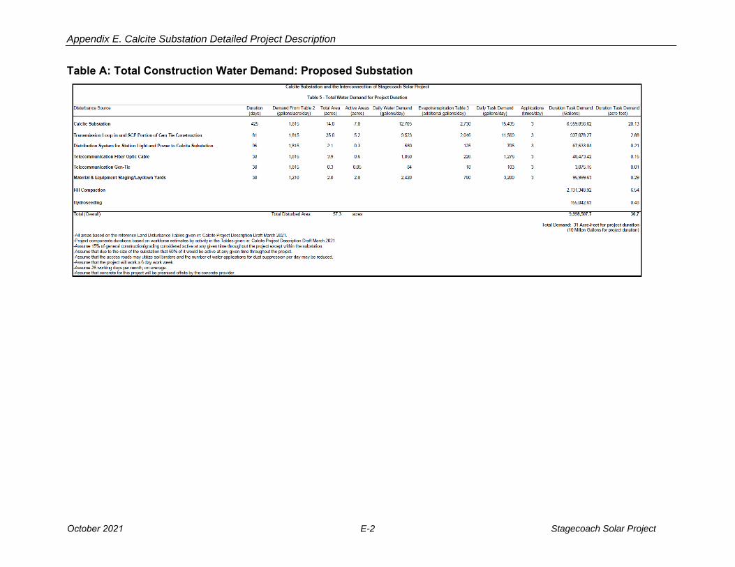
Appendix E. Calcite Substation Detailed Project Description
Table A: Total Construction Water Demand: Proposed Substation
October 2021 E-2 Stagecoach Solar Project
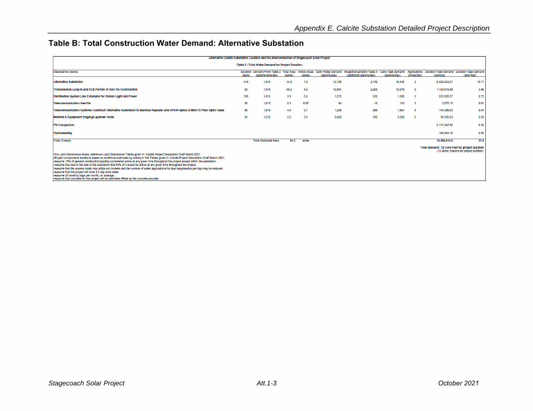
Appendix E. Calcite Substation Detailed Project Description
Table B: Total Construction Water Demand: Alternative Substation
Stagecoach Solar Project Att.1-3 October 2021
Figures
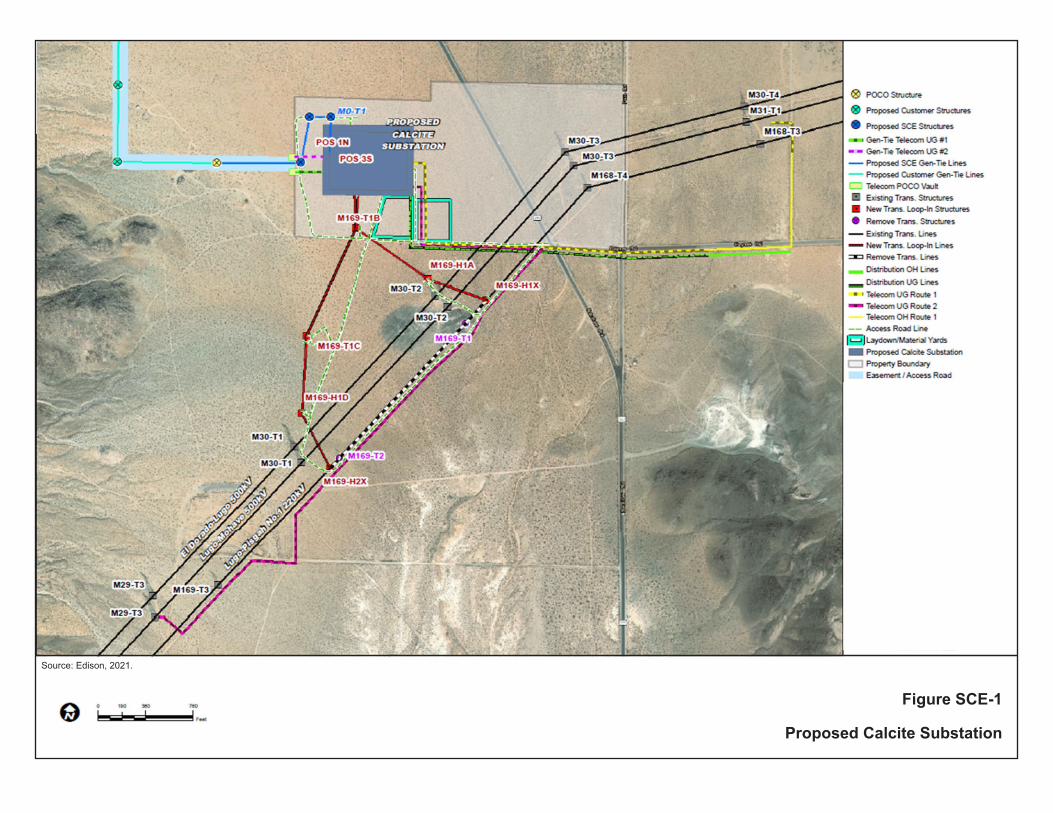
Source: Edison, 2021.
Figure SCE-1
Proposed Calcite Substation
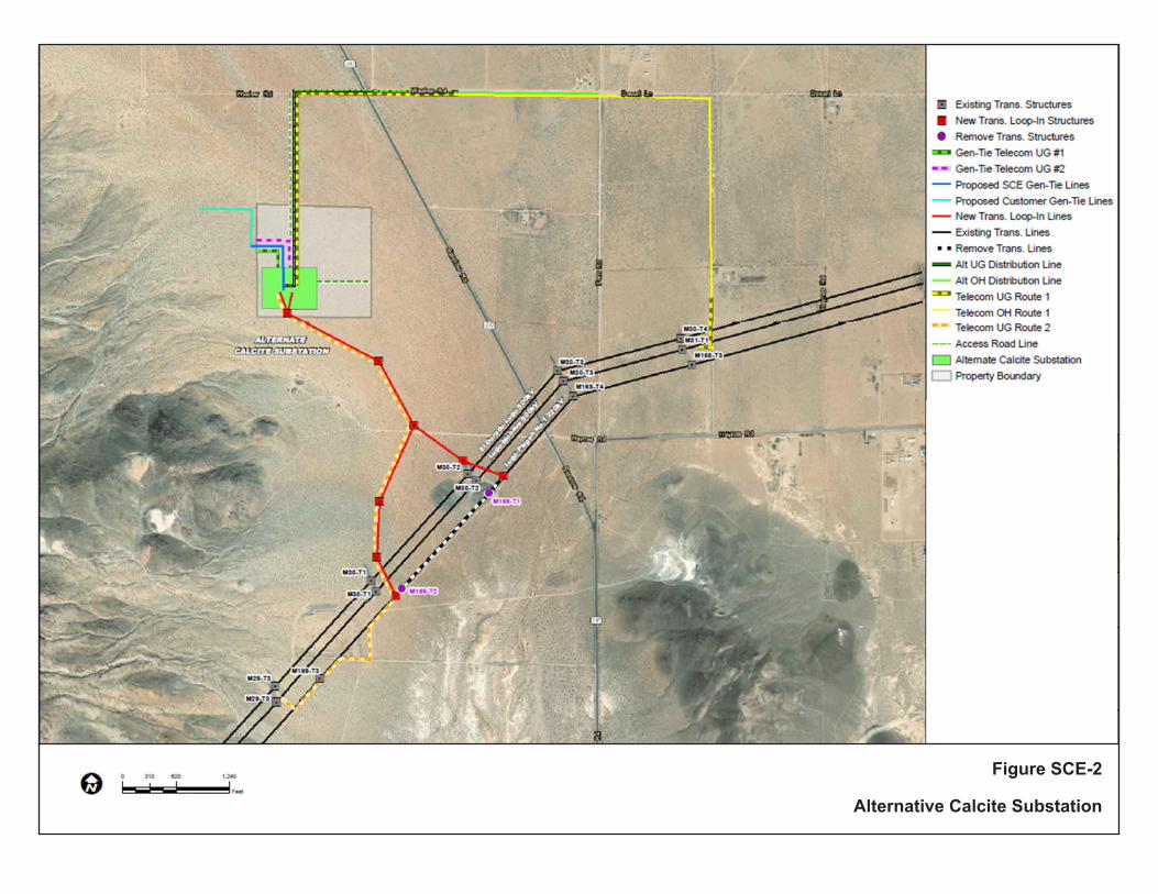
Figure SCE-2
Alternative Calcite Substation

Source: Edison, 2021. Figure SCE-3
Proposed Transmissionand Distribution Lines

Source: Edison, 2021. Figure SCE-4
220kV Tubular Steel Pole Configuration
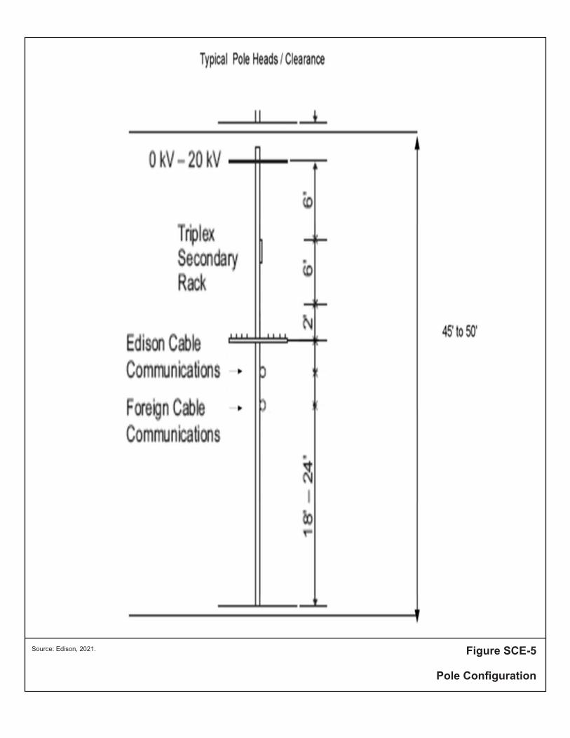
Source: Edison, 2021. Figure SCE-5
Pole Configuration
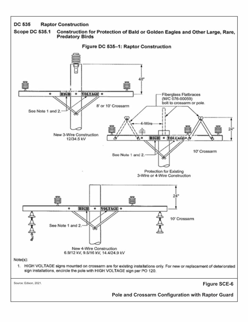
Source: Edison, 2021. Figure SCE-6
Pole and Crossarm Configuration with Raptor Guard

Source: Edison, 2021.
Figure SCE-7
Alternative Transmission and Distribution Lines