Embed Size (px)
Citation preview

APPENDIX D-3
TANKS
NYSDEC OHMS Document No. 201469232-00022

APPENDIX D-3 TANKS
TABLE OF CONTENTS
I. INTRODUCTION ........................................................................................................................ 1 II. TANKS AND THEIR SECONDARY CONTAINMENT SYSTEMS ...................................... 1 III. GENERAL PROCESS SYSTEMS .............................................................................................. 2 A. The Aqueous Waste Treatment Facility .......................................................................... 2 B. SLF 1-6 Leachate System. ................................................................................................ 8 C. SLF 7, 10 and 11 Leachate Systems ................................................................................ 9 D. SLF 12 Leachate System ................................................................................................ 11 E. RMU-1 Leachate System ............................................................................................... 12 F. Leachate Storage Tanks T-101, T-102, T-103 and Frac Tank #3 ................................. 13 G. Waste Stabilization Facility. .......................................................................................... 14 H. Truck Wash Facility. ...................................................................................................... 16 I. Groundwater Pumping Systems. .................................................................................... 17 J. Process and Secondary Containment Sump Systems .................................................... 18 K. Fuels Tanks ..................................................................................................................... 18
L. Fac Pond 5 Tank ............................................................................................................. 19 IV. PROCEDURES TO PREVENT HAZARDS ........................................................................ 1920 A. Inspections .................................................................................................................. 1920 B. Tank Inspection Criteria ............................................................................................. 1920 C. Tank Assessments ...................................................................................................... 1920 D. Overflow Protection ...................................................................................................... 201 E. Repairs ........................................................................................................................... 201 V. REQUIREMENTS FOR IGNITABLE, REACTIVE AND INCOMPATIBLE WASTE
STREAMS ................................................................................................................................ 212 VI. AIR EMISSION STANDARDS .............................................................................................. 212
Modified: Nov. 2013
NYSDEC OHMS Document No. 201469232-00022

TANKS I. INTRODUCTION
The CWM Model City Facility utilizes tanks for storing, treating and transferring many different materials including leachate, PCB liquids, organic liquids, products, aqueous waste, acids, caustics, sludges, recycle water, ground water, waste solids and lab waste.
All of the permitted tanks at the Model City Facility are listed in this Appendix.
II. TANKS AND THEIR SECONDARY CONTAINMENT SYSTEMS
The Permittee has constructed tankage specified in this Appendix with the required secondary containment and leak detection systems as specified in 6 NYCRR Part 373-2.10, except for Tank T-58 which was granted a variance from secondary containment requirements in CWM’s 2005 Part 373 Permit No. 9-2934-00022/00097. Drawings and secondary containment volume calculations for each tank area are provided in the attached System schematics. Process and Instrumentation Drawings (P&IDs) are also provided.
The secondary containment for tanks located inside buildings is provided by the building itself and designed to contain, at a minimum, 100% of the volume of the largest tank. Tanks located outside of buildings are provided with secondary containment designed to contain a minimum of 100% of the largest tank plus a 25 year, 24 hour storm event.
Precipitation that falls into outdoor secondary containment areas is typically collected and removed via pump, vacuum truck or equivalent and treated in the Aqueous Waste Treatment System, or if appropriate, tested and discharged to the surface water drainage system if analysis indicates that it meets surface water standards. Under normal circumstances, the secondary containment will be pumped free of liquid no later than the end of the next business day after the end of a rainfall event or thaw. All ancillary equipment for the permitted tank systems is provided with secondary containment, except for that ancillary equipment meeting the exemption specified in 6NYCRR 373-2.10(d)(6). All exempted ancillary equipment, e.g., welded piping, which is located outside of secondary containment, is visually inspected on a daily basis (except for groundwater extraction systems during the winter shut down period). All hazardous waste tank systems have been evaluated to determine if any such systems meet the definition of being interconnected, in accordance with 6NYCRR 370.2(b)(105). Criteria has been used to identify all areas where equipment failure at any point in the tank system or operator error could result in the release from more than one tank for tank systems interconnected in the same, or separate, secondary containments. As specified by 6NYCRR 373-2.10(d)(5)(i)(a), secondary containment systems must be designed or operated to contain 100% of the largest tank or the volume of all interconnected tanks, whichever is greater.
NYSDEC OHMS Document No. 201469232-00022

CWM has installed valving and electronic safeguards for all interconnected tanks at the Model City Facility whose combined volume exceeds the volume of secondary containment provided for these tanks to prevent potential secondary containment volume exceedences which could be caused by operator error.
III. GENERAL PROCESS SYSTEMS A. The Aqueous Waste Treatment Facility
CWM has engineered and constructed an Aqueous Wastewater Treatment System (AWTS) designed to treat on-site waters, landfill leachate and gate receipts from customers. The system occupies an area of approximately two acres, and is located at the western edge of the existing operating facility. The facility features enclosed tanks for receipt of waste materials, reaction vessels, filter presses for the removal of solids, biotowers for the removal of biodegradable organics (alcohols and ketones), carbon adsorbers for the capture of residual organics, cartridge filter units for removal of residual solids, adsorption media for removal of arsenic and storage tanks for the treated waste. The alkalization/precipitation, lime slurry, filter press and gate receipts receiving operations are housed in the 10,000 square foot Aqueous Treatment (A/T) Building along with the control room, laboratory and offices. The 1,500 square foot Water Treatment (W/T) Building houses the filtration, arsenic adsorption and carbon adsorption processes. The system features a Programmable Logic Controller (PLC) to monitor operations and transfers of materials within the facility. The PLC is also used to insure system safety by interlocking with various control equipment. The Aqueous Treatment and Water Treatment Buildings were designed to provide an environmentally safe water treatment operation. Environmental control was one of the primary objectives in the design and operation of the facility. The system features concrete containment surrounding all tanks, reaction vessels, and other process equipment. In addition, where needed, process piping is lined with special corrosion resistant plastic (polypropylene) or is constructed of High Density Polyethylene (HDPE) in order to prevent corrosion on the interior surface of the piping and prolong the process life of the piping. Finally, process tanks within the A/T Building are tied into a vent collection system. This system controls acid vapors associated with receipt and treatment of the waste materials. In addition, carbon canisters are installed on the process tanks which contain Subpart CC wastes to control organic emissions. The system is designed to be flexible in the treatment of waste streams. Flexibility is provided by the capability to by-pass or recirculate the process flow through major components of the treatment system. This allows for enhanced treatment and additional process capacity.
Modified: Nov. 2013
NYSDEC OHMS Document No. 201469232-00022

The incoming leachate, which is pretreated by oil/water separation when necessary, is pumped into the reaction/blending tanks where sulfuric acid and ferrous sulfate are added to lower the pH prior to metals precipitation, as needed and directed by the laboratory. Aqueous gate receipts can be mixed in the special treatment tanks and then transferred to the reaction/blending tanks. Each batch of blended waste is carefully prepared and analyzed by facility chemists. The aqueous wastes then go through an alkalization step and filtration unit to remove metal contaminants. The filter cake from the process is incinerated or transported to the site's secure landfill depending on the F039 analysis and achievement of land ban treatment standards. The treated effluent is then pumped into the biological treatment system (biotowers), where the wastewater undergoes biodegradation to remove organics. Flow is then processed through the cartridge filter and arsenic adsorption units (for aqueous wastes requiring arsenic removal) and carbon adsorption unit and on to the effluent holding tanks for testing prior to discharge to the facultative ponds. The biotowers can also be bypassed if organic constituent concentrations are low and the carbon treatment system can handle the organic load. The final treated effluent undergoes extensive laboratory testing and is discharged to the lower Niagara River under a state SPDES permit. While some AWTS tanks are used for storage only, various treatment options may be used in other tanks to facilitate the most efficient overall treatment, as listed in the following tank tables. For example, anti-foaming agents, nutrients and inoculum are typically added to lift station tanks T-3011 and T-3012 or tank T-3002 to improve organic reduction efficiency in the biotowers. Various agents may be added to filtrate storage tank T-100 and leachate tank farm tanks T-101, T-102 and T-103 to reduce the concentration of organics. Air sparging may be performed and various agents may be added to final effluent tanks T-58 and T-125 to reduce the concentration of organics. Hexametaphosphate is typically added to carbon adsorber feed tank T-3003 to prevent bridging of the carbon adsorbers. An oxidizer may be added to RMU-1 lift station tank T-160 to control the generation of hydrogen sulfide gas. A wide variety of other chemicals may also be used in any treatment tank depending on the type of treatment needed.
Modified: Nov. 2013
NYSDEC OHMS Document No. 201469232-00022

Aqueous Wastewater Treatment Building Tanks. TANK # OVERFILL CONTROL MATERIAL OF
CONSTRUCTION CAPACITY IN
GALLONS AND USAGE
CONTENTS GENERAL LOCATION
VERTICAL LOCATION
SECONDARY CONTAINMENT
VOLUME
REQUIRED CONTAINMENT
VOLUME
LEAK DETECTION
T-710 SPECIAL TREATMENT TANK
level indicator with high and high/high level alarms (PLC controlled)
FRP 8,000 storage/ treatment
aqueous waste
AWTS Building
above ground
24,440 gallons 10,000 gallons visual
T-810 SPECIAL TREATMENT TANK
level indicator with high and high/high level alarms (PLC controlled)
FRP 8,000 storage/ treatment
aqueous waste
AWTS Building
above ground
24,440 gallons 10,000 gallons visual
T-820 SPECIAL TREATMENT TANK
level indicator with high and high/high level alarms (PLC controlled)
FRP 8,000 storage/ treatment
aqueous waste
AWTS Building
above ground
24,440 gallons 10,000 gallons visual
T-850 SOLIDS DISSOLVING TANK
visual observation with inspection hatch
FRP 846 treatment
aqueous waste
AWTS Building
above ground
24,440 gallons 10,000 gallons visual
T-1010 METALS PRECIPITATION TANK
level indicator with high and high/high level alarms (PLC controlled)
Carbon steel 10,000 treatment
lime slurry/ aqueous waste
AWTS Building
above ground
24,440 gallons 10,000 gallons visual
T-1020 METALS PRECIPITATION TANK
level indicator with high and high/high level alarms (PLC controlled)
Carbon steel 8,000 treatment
lime slurry/ aqueous waste
AWTS Building
above ground
24,440 gallons 10,000 gallons visual
T-1111 FILTRATE TANK level indicator with high and high/high level alarms (PLC controlled)
Polyethylene 300 storage
aqueous waste
AWTS Building
above ground
24,440 gallons 10,000 gallons visual
T-1112 FILTRATE TANK
overflow pipe and level indicator with high and high/high level alarms (PLC controlled)
FRP 450 storage
aqueous waste
AWTS Building
above ground
24,440 gallons 10,000 gallons visual
T-1310 CAUSTIC SCRUBBER
level indicator with high level alarm (PLC controlled)
FRP 580 treatment
caustic solution / aqueous wastewater
AWTS Building
above ground
24,440 gallons 10,000 gallons visual
NYSDEC OHMS Document No. 201469232-00022

Solids Separation Building Tanks. TANK # OVERFLOW CONTROL MATERIAL OF
CONSTRUCTION CAPACITY IN
GALLONS AND USAGE
CONTENTS GENERAL LOCATION VERTICAL LOCATION
SECONDARY CONTAINMENT
VOLUME
REQUIRED CONTAINMEN
T VOLUME
LEAK DETECTION
T-3011 LIFT TANK
automatic shut off and level indicator with high and high/high level alarms (PLC controlled)
FRP 375 storage/ treatment
aqueous waste Solids Separator Building (South of AWTS Building)
above ground 14,851 gallons 4,291 gallons visual
T-3012 LIFT TANK
automatic shut off and level indicator with high and high/high level alarms (PLC controlled)
FRP 375 storage/ treatment
aqueous waste Solids Separator Building (South of AWTS Building)
above ground 14,851 gallons 4,291 gallons visual
Tanks North of AWTS Building.
TANK # OVERFLOW CONTROL MATERIAL OF CONSTRUCTION
CAPACITY IN GALLONS
AND USAGE
CONTENTS GENERAL LOCATION
VERTICAL LOCATION
SECONDARY CONTAINMENT
VOLUME
REQUIRED CONTAINMENT
VOLUME
LEAK DETECTION
T-100 FILTRATE STORAGE
level indicator with high and high/high level alarms (PLC controlled)
carbon steel 160,545 storage/ treatment
aqueous waste North of AWTS Building
above ground 571,328 gallons 424,410 gallons
visual/leak detection valve
T-125 EFFLUENT STORAGE
overflow pipe and level indicator with high level alarm (PLC controlled)
carbon steel 394,271 storage/ treatment
aqueous waste North of AWTS Building
above ground 571,328 gallons 424,410 gallons
visual/leak detection valve
Tanks West of AWTS Building.
TANK # OVERFLOW CONTROL
MATERIAL OF CONSTRUCTION
CAPACITY IN GALLONS AND
USAGE
CONTENTS GENERAL LOCATION
VERTICAL LOCATION
SECONDARY CONTAINMENT
VOLUME
REQUIRED CONTAINMENT
VOLUME
LEAK DETECTION
T-58 EFFLUENT STORAGE
level indicator with high level alarm (PLC controlled)
Glass fused carbon steel
488,529 storage/ treatment
aqueous waste East of AWTS Building
above ground see note see note leak detection pipe and valve
Note: A request for variance from secondary containment for Tank T-58 has been approved by NYSDEC.
NYSDEC OHMS Document No. 201469232-00022

Tanks East of AWTS Building. TANK # OVERFLOW CONTROL MATERIAL OF
CONSTRUCTION CAPACITY IN
GALLONS AND USAGE
CONTENTS GENERAL LOCATION
VERTICAL LOCATION
SECONDARY CONTAINMENT
VOLUME
REQUIRED CONTAINMENT
VOLUME
LEAK DETECTION
T-210 REACTION BLEND TANK
level indicator with high and high/high level alarms (PLC controlled)
carbon steel 30,000 treatment
aqueous waste Tank farm east of AWTS Building
above ground 44,350 gallons 36,903 gallons visual
T-220 REACTION BLEND TANK
level indicator with high and high/high level alarms (PLC controlled)
FRP 30,000 treatment
aqueous waste Tank farm east of AWTS Building
above ground 44,350gallons 36,903 gallons visual
T-230 REACTION BLEND TANK
level indicator with high and high/high level alarms (PLC controlled)
carbon steel 30,000 treatment
aqueous waste Tank farm east of AWTS Building
above ground 44,350gallons 36,903 gallons visual
T-310 BIOTOWER
automatic shut off and overflow pipe to clarifier tanks, equipped with pressure relief vent
FRP 30,457 treatment
aqueous waste Tank farm east of AWTS Building
above ground 44,350gallons 36,903 gallons visual
T-320 BIOTOWER
automatic shut off and overflow pipe to clarifier tanks, equipped with pressure relief vent
FRP 30,457 treatment
aqueous waste Tank farm east of AWTS Building
above ground 44,350gallons 36,903 gallons visual
Waste Water Treatment Building Tanks.
TANK # OVERFLOW CONTROL MATERIAL OF CONSTRUCTION
CAPACITY IN GALLONS AND
USAGE
CONTENTS GENERAL LOCATION
VERTICAL LOCATION
SECONDARY CONTAINMENT
VOLUME
REQUIRED CONTAINMENT
VOLUME
LEAK DETECTION
T-3007 CARBON ADSORBER
flow rate monitored at control panel and automatic feed pump shutoff
carbon steel 7,600 treatment
aqueous waste
WWT Building above ground
15,317 gallons 15,200 gallons visual
T-3008 CARBON ADSORBER
flow rate monitored at control panel and automatic feed pump shutoff
carbon steel 7,600 treatment
aqueous waste
WWT Building above ground
15,317 gallons 15,200 gallons
visual
T-3010A ARSENIC ADSORBER
Flow rate monitored at control panel and automatic feed pump shutoff
carbon steel 470 treatment
aqueous waste
WWT Building above ground
15,317 gallons 15,200 gallons visual
Modified: Nov. 2013
NYSDEC OHMS Document No. 201469232-00022

T-3010B ARSENIC ADSORBER
Flow rate monitored at control panel and automatic feed pump shutoff
carbon steel 470 treatment
aqueous waste
WWT Building above ground
15,317 gallons 15,200 gallons visual
T-3010C ARSENIC ADSORBER
Flow rate monitored at control panel and automatic feed pump shutoff
carbon steel 470 treatment
aqueous waste
WWT Building above ground
15,317 gallons 15,200 gallons visual
T-3010D ARSENIC ADSORBER
Flow rate monitored at control panel and automatic feed pump shutoff
carbon steel 470 treatment
aqueous waste
WWT Building above ground
15,317 gallons 15,200 gallons visual
Tanks South of Waste Water Treatment Building.
TANK # OVERFLOW CONTROL
MATERIAL OF CONSTRUCTION
CAPACITY IN GALLONS AND
USAGE
CONTENTS GENERAL LOCATION
VERTICAL LOCATION
SECONDARY CONTAINMENT
VOLUME
REQUIRED CONTAINMENT
VOLUME
LEAK DETECTION
T-52 CARBON TRANSFER TANK
overflow pipe to carbon adsorbers, equipped with pressure rupture disk
carbon steel 7,600 storage aqueous waste South of WWT Building
above ground 9,546 gallons 8,400 gallons Visual
Tanks East of Waste Water Treatment Building. TANK # OVERFLOW CONTROL MATERIAL OF
CONSTRUCTION CAPACITY IN
GALLONS AND USAGE
CONTENTS GENERAL LOCATION
VERTICAL LOCATION
SECONDARY CONTAINMENT
VOLUME
REQUIRED CONTAINMENT
VOLUME
LEAK DETECTION
T-3001 pH ADJUST TANK
automatic shut off and overflow pipe to T-3002
FRP 1,255 treatment
aqueous waste Tank farm east of WWT Building
above ground
1,872 gallons 1,549 gallons Visual
T-3002 BIOTOWER FEED TANK
automatic shut off and level indicator with high and high/high level alarms (PLC controlled)
FRP 900 treatment
aqueous waste Tank farm east of WWT Building
above ground
1,872 gallons 1,549 gallons Visual
T-3003 ADSORBER FEED TANK
automatic shut off and level indicator with high and high/high level alarms (PLC controlled)
FRP 1,210 storage/ treatment
aqueous waste Tank farm east of WWT Building
above ground
1,667 gallons 1,491 gallons Visual
T-3009 BACKWASH TANK
automatic shut off and level indicator with high and high/high level alarms (PLC controlled)
carbon steel 6,000 storage aqueous waste East of WWT Building
above ground
Double walled tank
N/A visual/leak detection valve
Modified: Nov. 2013
NYSDEC OHMS Document No. 201469232-00022

B. SLF 1-6 Leachate System
Oily leachate from SLF 1-6 can be pumped or transferred from the SLF 1-6 landfill leachate pumps into the SLF 1-6 lift station (T-105). The leachate received by the lift station is transferred by a pump into a surge tank (T-130). Oil and aqueous phases can be decanted and separately removed from T-130. Otherwise, mixed leachate is transferred to the SLF 1-11 Oil/Water Separator (T-158) by vacuum truck.
TANK # OVERFLOW CONTROL
MATERIAL OF CONSTRUCTION
CAPACITY IN GALLONS AND
USAGE
CONTENTS GENERAL LOCATION
VERTICAL LOCATION
SECONDARY CONTAINMENT
VOLUME
REQUIRED CONTAINMENT
VOLUME
LEAK DETECTION
T-105 LIFT STATION
automatic shut off and level indicator with high and high/high level alarms (PLC controlled)
carbon steel 3,000 storage Leachate SLF 1-6 above ground 4,143 gallons 3,000 gallons visual
T-130 SURGE TANK
automatic shut off and level indicator with high and high/high level alarms (PLC controlled)
stainless steel 5,732 storage Leachate SLF 1-6 above ground 8,228 gallons 6,819 gallons visual
NYSDEC OHMS Document No. 201469232-00022

C. SLF 7, 10 and 11 Leachate Systems
Leachate generated by SLF 7, 10 and 11 is pumped from the SLF 7, 10 and 11 landfill leachate pumps into the associated lift station tank (T-107, T-110 and T-111). The leachate received by the lift station is pumped to holding tanks (T-108 and T-109) from which it is removed by vacuum truck and transferred to the T-200 series tanks or the SLF 1-11 Oil/Water Separator (T-158), which may also be used for various offsite commercial and onsite generated aqueous wastes. Oil from T-158 is transferred to vacuum trucks for offsite disposal. The aqueous phase from T-158 is transferred to tank T-159 and pumped to the Leachate Tank Farm. SLF 7 leachate may also be removed from T-107 by vacuum truck and transferred to AWT for treatment and/or transferred to an outbound tanker for treatment or disposal.
TANK # OVERFLOW CONTROL MATERIAL OF
CONSTRUCTION CAPACITY IN
GALLONS AND USAGE
CONTENTS GENERAL LOCATION
VERTICAL LOCATION
SECONDARY CONTAINMENT
VOLUME
REQUIRED CONTAINMENT
VOLUME
LEAK DETECTION
T-107 SLF 7 WET WELL TANK
automatic shut off and level indicator with high and high/high level alarms (PLC controlled)
FRP 350 storage
leachate SLF 7 aboveground 2,765 gallons 350 gallons visual
T-110 SLF 10 WET WELL TANK
automatic shut off and level indicator with high and high/high level alarms (PLC controlled)
FRP 350 storage
leachate SLF 10 aboveground 15,709 gallons 3,000 gallons visual
T-111 SLF 11 WET WELL TANK
automatic shut off and level indicator with high and high/high level alarms (PLC controlled)
FRP 350 storage
leachate SLF 11 aboveground 15,709 gallons 10,000 gallons visual
T-108 SLF 7/11 HOLD TANK
automatic shut off and level indicator with high and high/high level alarms (PLC controlled)
FRP 10,000 storage
leachate SLF 11 aboveground 15,709 gallons 10,000 gallons visual
T-109 SLF 10 HOLD TANK
automatic shut off and level indicator with high and high/high level alarms (PLC controlled)
FRP 3,000 storage
leachate SLF 10 aboveground 15,709 gallons 3,000 gallons visual
NYSDEC OHMS Document No. 201469232-00022

SLF 1-11 Oil/Water Separator Building
TANK # OVERFLOW CONTROL MATERIAL OF CONSTRUCTION
CAPACITY IN GALLONS
AND USAGE
CONTENTS GENERAL LOCATION
VERTICAL LOCATION
SECONDARY CONTAINMENT
VOLUME
REQUIRED CONTAINMENT
VOLUME
LEAK DETECTION
T-158 OIL/WATER SEPARATOR TANK
automatic shut off and level indicator with high and high/high level alarms (PLC controlled)
steel 17,000 treatment
leachate, offsite and onsite aqueous wastes
East of Leachate Tank Farm
aboveground 24,876 gallons 17,000 gallons visual
T-159 AQUEOUS TANK
automatic shut off and level indicator with high and high/high level alarms (PLC controlled)
FRP 1,000 storage
leachate, aqueous wastes
East of Leachate Tank Farm
aboveground 24,876 gallons 17,000 gallons visual
NYSDEC OHMS Document No. 201469232-00022

D. SLF 12 Leachate System
Leachate generated by SLF 12 is pumped from the SLF 12 landfill leachate pumps into the SLF 12 lift station tank (T-150). Nonhazardous onsite generated aqueous wastes (i.e., site waters) may also be added to tank T-150. The aqueous wastes received by the lift station are transferred by a pump to the Leachate Tank Farm through above ground piping.
TANK # OVERFLOW CONTROL MATERIAL OF
CONSTRUCTION CAPACITY IN
GALLONS AND USAGE
CONTENTS GENERAL LOCATION
VERTICAL LOCATION
SECONDARY CONTAINMENT
VOLUME
REQUIRED CONTAINMENT
VOLUME
LEAK DETECTION
T-150 LIFT STATION
control level indicator and controller
carbon steel 8,000 storage /treatment
leachate, onsite generated aqueous wastes
SLF 12 Lift Station above ground 18,388 gallons 8,000 gallons visual
Tank T-160 and Lift Station for RMU-1 are located within the northern footprint of the new Residuals Management Unit No. 2 (RMU-2) landfill. Tank T-160 and Lift Station will be closed in accordance with the Sitewide Closure Plan and will be demolished for the construction of the later northern phases of RMU-2. Therefore, new underground piping from RMU-1 will be installed to transfer leachate to tank T-150. Additionally, RMU-2 leachate will be pumped to T-150 through new underground piping. T-150 will be upgraded with new pumps to management the leachate from SLF-12 and RMU-1 and proposed RMU-2. The existing above ground piping used for transferring aqueous wastes from T-150 to the Leachate Tank Farm will be replaced with underground piping.
NYSDEC OHMS Document No. 201469232-00022

E. RMU - 1 Leachate System
Leachate generated by RMU-1 is pumped from the RMU-1 landfill leachate pumps and tank T-165 into the RMU-1 lift station tank (T-160). The leachate received by the lift station is transferred by pump through double walled underground piping and aboveground piping, then to the Leachate Tank Farm through aboveground piping.
TANK # OVERFLOW CONTROL MATERIAL OF
CONSTRUCTION CAPACITY IN
GALLONS AND USAGE
CONTENTS GENERAL LOCATION
VERTICAL LOCATION
SECONDARY CONTAINMENT
VOLUME
REQUIRED CONTAINMENT
VOLUME
LEAK DETECTION
T-160 LIFT STATION automatic shut off and level indicator with high and high/high level alarms (PLC controlled)
carbon steel 3,000 storage/ treatment
leachate RMU-1 Landfill
above ground 7,563 gallons 3,000 gallons Visual
T-165 automatic shut off and level indicator with high and high/high level alarms
Glass fused carbon steel
876,769 storage
leachate RMU-1 Landfill
above ground 913,155 gallons
889,529 gallons
Visual
Tank T-160 and Lift Station are located within the footprint of the new Residuals Management Unit No. 2 (RMU-2) landfill. Tank T-160 and Lift Station will be closed in accordance with the Sitewide Closure Plan and will be demolished for the construction of later phases of RMU-2. Tank T-165 will be retained for management of leachate from RMU-1.
NYSDEC OHMS Document No. 201469232-00022

F. Leachate Storage Tanks T-101, T-102, T-103 and Frac Tank #3
The Leachate Tank Farm contains three (3) leachate storage tanks which are used to collect the aqueous phase leachate from active and closed landfills as well as other site waters. The leachate is held in the tanks and transferred to the AWTS on a demand basis. Also, located within this secondary containment area is Frac Tank # 3 which is used for storage of aqueous waste prior to treatment at the AWTS or SLF 7 leachate prior to offsite shipment for treatment or incineration.
TANK # OVERFLOW CONTROL MATERIAL OF CONSTRUCTION
CAPACITY IN GALLONS
AND USAGE
CONTENTS GENERAL LOCATION
VERTICAL LOCATION
SECONDARY CONTAINMENT
VOLUME
REQUIRED CONTAINMENT
VOLUME
LEAK DETECTION
T-101 STORAGE (southern)
level indicator and controller and overflow pipe to sump
carbon steel 350,000 storage/ treatment
aqueous waste
East of North Salts
above ground 500,959 gallons
392,765 gallons
visual
T-102 STORAGE (middle)
level indicator and controller and overflow pipe to sump
carbon steel 350,000 storage/ treatment
aqueous waste
East of North Salts
above ground 500,959 gallons
392,765 gallons
visual
T-103 STORAGE (northern)
level indicator and controller and overflow pipe to sump
carbon steel 350,000 storage/ treatment
aqueous waste
East of North Salts
above ground 500,959 gallons
392,765 gallons
visual
FRAC TANK #3 level indicator with high and high/high level alarms (PLC controlled)
carbon steel 21,000 storage
aqueous waste
East of North Salts
above ground 500,959 gallons
392,765 gallons
visual
NYSDEC OHMS Document No. 201469232-00022

G. Waste Stabilization Facility
Stabilization is a process that results in the reduction in the mobility (or leachability) of hazardous components within a hazardous waste matrix. This stabilization is accomplished by inducing a chemical reaction between the hazardous components and one or more reagents, such as cement, cement kiln dust, lime, flyash or other pozzolanic materials. Typical materials to be stabilized are inorganic waste water treatment sludges, media with metals, contaminated soils, sand blast grit, incinerator ash, incinerator slag, emissions control dust and debris. These waste streams are chemically compatible and have no reactive properties, therefore, compatibility concerns are minimal. Waste Profiles are carefully reviewed for EPA codes, components, types of metals present and stabilization recipe (type and quantity of reagents). Generally, bulk loads are processed as individual batches. Drum or other small quantities of waste and bulk loads that have similar characteristics, non-conflicting EPA waste codes and the same stabilization recipe may be combined to increase the batch size for processing. Waste water from equipment wash down or compatible hazardous and non-hazardous gate receipts may be used as the water source in the recipe. The EPA codes will be tracked through the process tankage and the impact on the treatment standards will be assessed for each batch prior to processing. Alternatively, city water or non-hazardous site waters may be used to avoid code conflict. The bulk waste material to be stabilized arrives at the site in dump trailers, rolloff boxes, drums, pneumatic trailers, and other types of containers. The waste can be wet, sticky, cohesive, dusty and contain rock, pipe sections, metal, concrete, rags, wire and other debris. The majority of the waste that requires stabilization is deposited in a mixing basin. Reagents are metered into the basin in accordance with a predetermined recipe. Water is added to the mixture, and the waste with reagent and water is mixed to a homogeneous mixture. The stabilized waste mixture is then removed from the pit with a backhoe, loaded into a dump truck or container, and transported to the landfill or an off-site disposal facility. Waste in drums can be emptied into the pit using a forklift and drum handler or placed full into the pit and broken apart with the mixing backhoe.
NYSDEC OHMS Document No. 201469232-00022

Microencapsulation is a specified technology involving the immobilization of contaminants on debris by stabilization. Stabilization treatment is performed in the mixing basin (pit) system. As it is not possible to develop a waste stream specific recipe, the requirement is to utilize sufficient stabilization media to treat all surfaces. For material or debris that is not easily manageable in the mixing pits, a slurry of stabilization media can be mixed in the pit and transferred into the waste container where the material will be encapsulated. Debris that may not be physically suitable for the stabilization equipment, or that contains organic contamination (e.g. pump contaminated with leachate) may be managed by macroencapsulation. This type of debris is placed in a non-degradable container such as a poly drum or HDPE box. The void space is then eliminated by the addition of stabilization material that does not need to be held and tested or other non-degradable absorbent/space filler. The container is then permanently sealed and disposed of in the landfill.
Stabilization-Northern Expansion Tanks
TANK # OVERFLOW CONTROL
MATERIAL OF CONSTRUCTION
CAPACITY IN GALLONS AND
USAGE
CONTENTS GENERAL LOCATION
VERTICAL LOCATION
SECONDARY CONTAINMENT
VOLUME
REQUIRED CONTAINMENT
VOLUME
LEAK DETECTION
MIXING PIT 1 visual observation during operation
carbon steel 20,354 treatment
RCRA/TSCA wastes
Stab. Northern Expansion
underground Double walled underground tank
Double walled underground tank
sensor probe
MIXING PIT 2 visual observation during operation
carbon steel 20,354 treatment
RCRA/TSCA wastes
Stab. Northern Expansion
underground Double walled underground tank
Double walled underground tank
sensor probe
Stabilization-Southern Expansion Tanks
TANK # OVERFLOW CONTROL
MATERIAL OF CONSTRUCTION
CAPACITY IN GALLONS AND
USAGE
CONTENTS GENERAL LOCATION
VERTICAL LOCATION
SECONDARY CONTAINMENT
VOLUME
REQUIRED CONTAINMENT
VOLUME
LEAK DETECTION
TA-1 PROCESS WATER
high level indicator
rubber lined carbon steel
20,000 storage aqueous waste, miscellaneous site waters
Stab. Southern Expansion
above ground 28,174 gallons 24,739 gallons visual
TA-2 PROCESS WATER
high level indicator
rubber lined carbon steel
20,000 storage aqueous waste, miscellaneous site waters
Stab. Southern Expansion
above ground 28,174 gallons 24,739 gallons visual
NYSDEC OHMS Document No. 201469232-00022
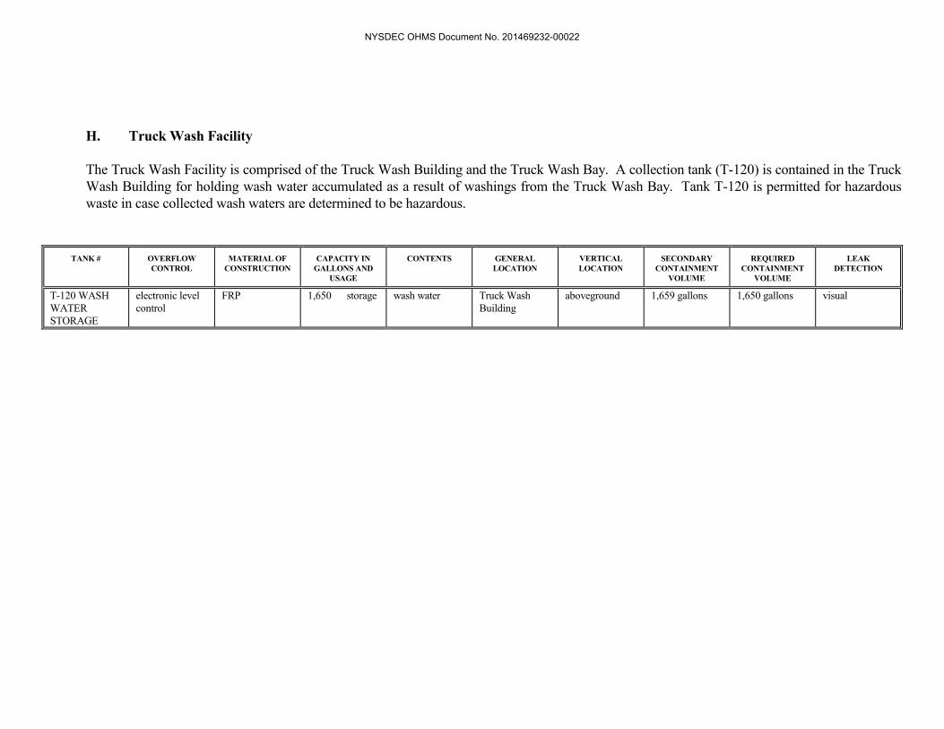
H. Truck Wash Facility
The Truck Wash Facility is comprised of the Truck Wash Building and the Truck Wash Bay. A collection tank (T-120) is contained in the Truck Wash Building for holding wash water accumulated as a result of washings from the Truck Wash Bay. Tank T-120 is permitted for hazardous waste in case collected wash waters are determined to be hazardous.
TANK # OVERFLOW
CONTROL MATERIAL OF
CONSTRUCTION CAPACITY IN
GALLONS AND USAGE
CONTENTS GENERAL LOCATION
VERTICAL LOCATION
SECONDARY CONTAINMENT
VOLUME
REQUIRED CONTAINMENT
VOLUME
LEAK DETECTION
T-120 WASH WATER STORAGE
electronic level control
FRP 1,650 storage wash water Truck Wash Building
aboveground 1,659 gallons 1,650 gallons visual
NYSDEC OHMS Document No. 201469232-00022

I. Groundwater Pumping Systems
The groundwater pumping system tanks were constructed as part of the Corrective Measures Program at Model City. Originally installed as Interim Corrective Measures to check the spread of groundwater contamination and, ultimately, to improve groundwater quality in the affected areas, these systems were determined to be capable of achieving the goals of the Corrective Action Program and were made Final Corrective Measures by the NYSDEC on February 13, 2001.
TANK # OVERFLOW CONTROL MATERIAL OF
CONSTRUCTION TANK CAPACITY IN GALLONS AND
USAGE
CONTENTS GENERAL LOCATION
VERTICAL LOCATION
SECONDARY CONTAINMENT
VOLUME
REQUIRED CONTAINMENT
VOLUME
LEAK DETECTION
T-8001 level indicator with high and high/high level alarms (PLC controlled)
carbon steel 5,000 storage groundwater West Drum Area above ground 6,445 gallons 5,000 gallons visual
T-8002 level indicator with high and high/high level alarms (PLC controlled)
FRP 550 storage groundwater West Drum Area above ground 6,445 gallons 5,000 gallons visual
T-8004 level indicator (PLC controlled)
FRP 550 storage groundwater South of SLF 3 above ground 892 gallons 550 gallons visual
T-8005 automatic shut off and high level alarm
carbon steel 300 storage groundwater South of SLF 10 above ground 356 gallons 300 gallons visual
T-8006 automatic shut off and high level alarm
carbon steel 300 storage groundwater East of SLF 12 above ground 356 gallons 300 gallons visual
T-8007 automatic shut off and high level alarm
FRP 500 storage groundwater South of PCB Warehouse
above ground 539 gallons 500 gallons visual
T-8008 automatic shut off and high level alarm
FRP 500 storage DNAPL Tank T-125/T-100 Area
above ground 571,328 gallons 424,410 gallons visual
T-8009 automatic shut off and high level alarm
HDLPE 525 storage groundwater Inside T.O. Building CSA
above ground 853 gallons 525 gallons visual
T-8010 automatic shut off and high level alarm
HDPE 1,000 storage groundwater South of South Trailer Parking CSA
above ground 1,300 gallons 1,000 gallons visual
NYSDEC OHMS Document No. 201469232-00022
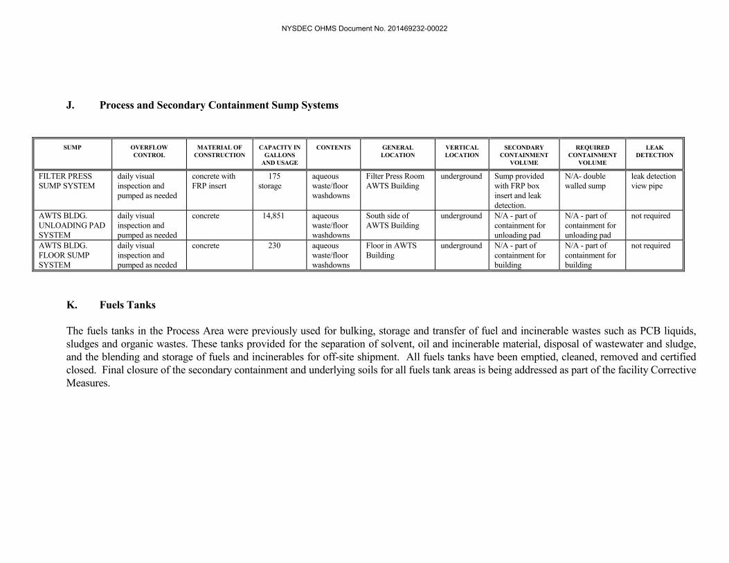
J. Process and Secondary Containment Sump Systems
SUMP OVERFLOW
CONTROL MATERIAL OF
CONSTRUCTION CAPACITY IN
GALLONS AND USAGE
CONTENTS GENERAL LOCATION
VERTICAL LOCATION
SECONDARY CONTAINMENT
VOLUME
REQUIRED CONTAINMENT
VOLUME
LEAK DETECTION
FILTER PRESS SUMP SYSTEM
daily visual inspection and pumped as needed
concrete with FRP insert
175 storage
aqueous waste/floor washdowns
Filter Press Room AWTS Building
underground Sump provided with FRP box insert and leak detection.
N/A- double walled sump
leak detection view pipe
AWTS BLDG. UNLOADING PAD SYSTEM
daily visual inspection and pumped as needed
concrete 14,851 aqueous waste/floor washdowns
South side of AWTS Building
underground N/A - part of containment for unloading pad
N/A - part of containment for unloading pad
not required
AWTS BLDG. FLOOR SUMP SYSTEM
daily visual inspection and pumped as needed
concrete 230 aqueous waste/floor washdowns
Floor in AWTS Building
underground N/A - part of containment for building
N/A - part of containment for building
not required
K. Fuels Tanks
The fuels tanks in the Process Area were previously used for bulking, storage and transfer of fuel and incinerable wastes such as PCB liquids, sludges and organic wastes. These tanks provided for the separation of solvent, oil and incinerable material, disposal of wastewater and sludge, and the blending and storage of fuels and incinerables for off-site shipment. All fuels tanks have been emptied, cleaned, removed and certified closed. Final closure of the secondary containment and underlying soils for all fuels tank areas is being addressed as part of the facility Corrective Measures.
NYSDEC OHMS Document No. 201469232-00022

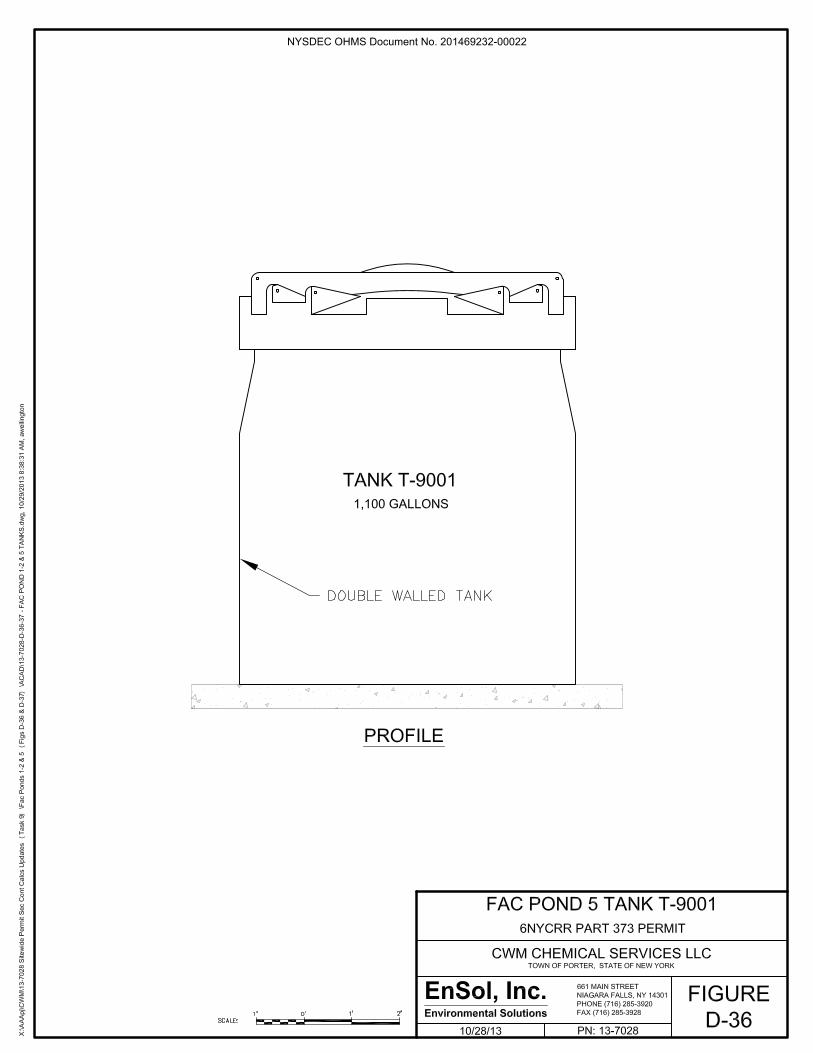
L. Fac Pond 5 Tank The Fac Pond 5 tank will be located on the berm of the surface impoundment. The tank will store waters pumped from the secondary collection sump of the impoundment. The surface impoundment (facultative pond) is used for storage of treated effluent from the AWTS.
TANK # OVERFLOW CONTROL MATERIAL OF CONSTRUCTION
CAPACITY IN GALLONS AND
USAGE
CONTENTS GENERAL LOCATION
VERTICAL LOCATION
SECONDARY CONTAINMENT
VOLUME
REQUIRED CONTAINMENT
VOLUME
LEAK DETECTION
T-9001 automatic shut off and level indicator with high level alarm
HDPE 1,100 storage Secondary Leachate/Leak detection waters
East Berm of Fac Pond 5
above ground
Double walled tank
N/A visual/leak detection valve
NYSDEC OHMS Document No. 201469232-00022

IV. PROCEDURES TO PREVENT HAZARDS A. Inspections
Tanks will be inspected and evaluated according to the procedures and schedules provided in the CWM Inspection Plan.
B. Tank Inspection Criteria
Environmental Compliance Tank Inspection Criteria will generally include inspection items such as:
• above ground tank exterior free of signs of leakage, including discoloration that may be
a residue of a prior release. • above ground tank exterior free of signs of deterioration that could lead to potential
leakage, including cracks, corrosion, defects, and obvious deformation. • above ground tank ancillary equipment free of signs of leakage • secondary containment shows no visible evidence of spills • secondary containment intact and free of cracks which exhibit separation and coating is
free of chips which expose the underlying concrete • secondary containment not holding liquids for more than is allowable under the
Inspection Plan • overfill controls (where present) do not indicate overflow condition; overfill controls
(where present) are operable • liquids (not including condensate) not present in leak detection systems (visual or
electronic indication); electronic leak detection systems (where present) are operable C. Tank Assessments
All permitted hazardous waste tank systems must undergo a periodic assessment performed by an independent professional engineer who must certify that the tank is fit for continued use. Generally, all above ground tanks with secondary containment and leak detection are assessed once every five years. For certain tanks, an internal inspection is also required. The double walled, underground stabilization mixing pits and the AWTS floor sump are subjected to an annual, internal assessment. The assessment frequency and whether the tank will be internally inspected are specified in the attached Tank Assessment Schedule. In
NYSDEC OHMS Document No. 201469232-00022

addition, all secondary containments and sumps associated with permitted tank systems are inspected by a qualified inspector every year. Tank assessment and secondary containment inspection reports are submitted to the NYSDEC each year. Tanks T-3010A, T-3010B, T-3010C, and T-3010D are part of the arsenic treatment system and will be periodically changed out as part of normal operations. During regular tank change out installations, CWM personnel will inspect the system components prior to start up to insure they are installed properly. In addition, the tanks, along with the associated flexible hoses and their connections, involved in the change out will be re-tested for tightness in accordance with the procedure specified in Section 3.2 of the “Tank System Design and Assessment Report for AWTS Arsenic Removal Tanks T-3010A/B/C/D”. Also, prior to start up, CWM will comply with the requirements in Condition C.1.i.ii.”b” of Exhibit D in Schedule 1 of Module I of the Permit. During start up after tank change out, CWM will visually inspect the system components to insure they are free of leaks and that any deficiencies are addressed immediately. Documentation of each tank change out, and associated tightness testing and installation inspections will be maintained on-site for Department review.
D. Overflow Protection
Generally, most tanks within the AWT system are connected to a programmable logic controller (PLC). This unit is programmed to continuously monitor tank level, pump status and valve positions for the process vessels. The logic in the PLC is arranged so that pumps are shut down should levels become too low or reach a pre-determined high or high-high level.
Tanks that are not equipped with mechanical or electronic overflow protection generally contain an overflow pipe which is directed into the tank's secondary containment. As part of normal operations, the process operators and department supervisors make visual checks of the status of the operation. Overflow conditions would be identified at that time. In addition, the Site Inspector inspects each permitted tank on a daily basis.
E. Repairs
When a system deficiency is identified by any of the above inspection programs, it will generally be repaired immediately, if possible. Otherwise, action will be initiated with an environmental or maintenance work order by the end of the next business day. The time period to complete a repair varies depending on the type and extent of the deficit. Some repairs, such as outdoor concrete work or coating applications cannot be efficiently completed during winter conditions. Major defects affecting human health or the environment such as a tank leak, require immediate action by taking the unit out of service. After repairs have been completed, the area will be re-inspected and the repairs will be documented on the work order or by a subsequent tank assessment or secondary containment inspection report.
Modified: Nov. 2013
NYSDEC OHMS Document No. 201469232-00022

V. REQUIREMENTS FOR IGNITABLE, REACTIVE AND INCOMPATIBLE
WASTE STREAMS
The facility Waste Analysis Plan addresses the special hazards and compatibility concerns for tank storage. Ignitable or reactive wastes will only be placed in tanks which are designed for storage of ignitable or reactive wastes unless the tank is used for an emergency. The aqueous waste treatment system is equipped with treatment tanks designed to react and mix wastewaters requiring special treatment or handling techniques. These tanks are closed top tanks meeting the buffer zone requirements of NFPA Combustible Liquids Code (1984). All tanks must be at least 50 feet internal to property lines or public roadways. NFPA 30 sets minimum buffer distances required for Class I, II and IIIB materials at 5 feet from a building. The distance increases depending on capacity.
Process wastewater, other site water or city water may be added prior to the addition of concentrated incoming wastewaters to control the generation of significant heat during mixing. All reaction vessels and tanks which could be subject to significant chemical reactions are equipped with the appropriate level, pH and/or temperature monitoring devices.
Mixing of incompatible wastes, which could produce an uncontrolled reaction is avoided by adhering to a prescribed process for purging and flushing of all process lines and tanks following transfer operations.
Incompatible wastes which could produce an uncontrolled reaction will not be mixed in storage tanks. Control of waste mixtures in storage tanks will be accomplished by actual laboratory bench tests if the material to be stored in a tank is different than the existing stored material.
Procedures to prevent incompatible mixtures in tanks are detailed in the Waste Analysis Plan. Materials that indicate signs of reaction which may exceed the design specifications of the vessel will not be stored in the same tank. Hazardous wastes will not be placed into an unwashed tank which previously held an incompatible waste or material.
VI. AIR EMISSION STANDARDS
Air emission standards for tanks are specified in 6NYCRR 373-2.29 and 40CFR 264/265.1080-1091 (Subpart CC), which became effective on December 6, 1996. RCRA Subpart CC is applicable to owners and operators of a TSDF which treats, stores or disposes of hazardous waste containing greater than 500 ppmw volatile organics in tanks, surface impoundments and containers. If Subpart CC wastes are managed in tanks, either Level 1 or Level 2 controls must be implemented.
NYSDEC OHMS Document No. 201469232-00022
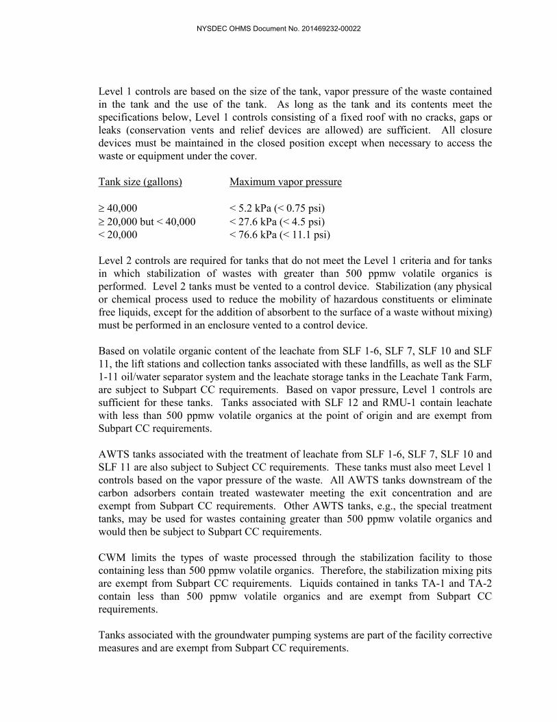
Level 1 controls are based on the size of the tank, vapor pressure of the waste contained in the tank and the use of the tank. As long as the tank and its contents meet the specifications below, Level 1 controls consisting of a fixed roof with no cracks, gaps or leaks (conservation vents and relief devices are allowed) are sufficient. All closure devices must be maintained in the closed position except when necessary to access the waste or equipment under the cover. Tank size (gallons) Maximum vapor pressure ≥ 40,000 < 5.2 kPa (< 0.75 psi) ≥ 20,000 but < 40,000 < 27.6 kPa (< 4.5 psi) < 20,000 < 76.6 kPa (< 11.1 psi) Level 2 controls are required for tanks that do not meet the Level 1 criteria and for tanks in which stabilization of wastes with greater than 500 ppmw volatile organics is performed. Level 2 tanks must be vented to a control device. Stabilization (any physical or chemical process used to reduce the mobility of hazardous constituents or eliminate free liquids, except for the addition of absorbent to the surface of a waste without mixing) must be performed in an enclosure vented to a control device. Based on volatile organic content of the leachate from SLF 1-6, SLF 7, SLF 10 and SLF 11, the lift stations and collection tanks associated with these landfills, as well as the SLF 1-11 oil/water separator system and the leachate storage tanks in the Leachate Tank Farm, are subject to Subpart CC requirements. Based on vapor pressure, Level 1 controls are sufficient for these tanks. Tanks associated with SLF 12 and RMU-1 contain leachate with less than 500 ppmw volatile organics at the point of origin and are exempt from Subpart CC requirements. AWTS tanks associated with the treatment of leachate from SLF 1-6, SLF 7, SLF 10 and SLF 11 are also subject to Subject CC requirements. These tanks must also meet Level 1 controls based on the vapor pressure of the waste. All AWTS tanks downstream of the carbon adsorbers contain treated wastewater meeting the exit concentration and are exempt from Subpart CC requirements. Other AWTS tanks, e.g., the special treatment tanks, may be used for wastes containing greater than 500 ppmw volatile organics and would then be subject to Subpart CC requirements. CWM limits the types of waste processed through the stabilization facility to those containing less than 500 ppmw volatile organics. Therefore, the stabilization mixing pits are exempt from Subpart CC requirements. Liquids contained in tanks TA-1 and TA-2 contain less than 500 ppmw volatile organics and are exempt from Subpart CC requirements. Tanks associated with the groundwater pumping systems are part of the facility corrective measures and are exempt from Subpart CC requirements.
NYSDEC OHMS Document No. 201469232-00022

APPENDIX D-3, SECTION VII
TANK ANCILLARY EQUIPMENT
TIGHTNESS TESTING PROCEDURES FOR
UNDERGROUND HAZARDOUS WASTE TRANSFER LINES
NYSDEC OHMS Document No. 201469232-00022

VII. Procedures for Pressure Testing of Underground Hazardous Waste Transfer Lines
The procedures in this section are not required for leachate piping under waste within the boundaries of a landfill liner and piping associated with the river discharge of treated wastewater.
1. Procedures for Hydrostatic Testing the Inner Carrier Pipe of Double-Walled
Underground Transfer Lines:
The Permittee shall perform either of the two (2) hydrostatic test procedures specified below, as derived from the “Plastic Pipe Institute=s (PPI=s) Technical Report 31 (TR-31)”. The Permittee, at its discretion, may use a “tracer” (e.g., dye, etc.) in the water used in these tests to differentiate it from other liquids that may be present. The pressure measurement device used in either of these procedures must be incremented at, and sensitive to pressure fluctuations of 1 psi or less. Also, regardless of which test is used, the Permittee shall, throughout the test=s duration, periodically inspect the down-gradient end of the outer containment pipe associated with the section of inner carrier pipe being tested, for signs of liquid discharge. If liquid discharge is observed, or if a tracer is used and it is detected in the liquid, it shall be assumed to be leakage.
a. Pressure Drop Procedure -
1. Pipe to be tested shall be filled with fresh water or Department
approved alternate, and have all air bled off from its highest point. 2. Pipe shall be pressurized to not less than 1.5 times the system
operating pressure with a minimum of 11 psi. 3. Maintain this test pressure for four (4) hours by adding sufficient
liquid at hourly intervals as necessary, to each time re-establish the test pressure.
4. Drop the pressure by 10 psi, and measure and record the pressure one (1) hour thereafter. If the final pressure is within 5% of this reduced pressure, the pipe has passed the test.
If any pipe fails to pas the above test, prior to initiating any leak location and repair activities, the Permittee, at its discretion, may perform the Volume Loss Procedure specified in Sub-section Ab@ below to verify that the pressure loss is not due to pipe expansion.
b. Volume Loss Procedure -
1. Pipe to be tested shall be filled with fresh water or Department
approved alternate, and have all air bled off from its highest point.
NYSDEC OHMS Document No. 201469232-00022

2. Pipe shall be pressurized to not less than 1.5 times the system
operating pressure with a minimum of 11 psi. 3. Maintain this test pressure to compensate for pipe expansion for
four (4) hours by adding sufficient liquid at hourly intervals as necessary, to each time re-establish the test pressure.
4. After the four (4) hour expansion period, the test period shall begin lasting a maximum of three (3) hours. At hourly intervals, liquid shall be added as necessary, to each time re-establish the test pressure. The amount of liquid which is added, if any, shall be measured and recorded each hour.
5. The amount of liquid added after the first hour of the test period and, if necessary, the cumulative amounts added after hours two (2) and three (3), shall be compared to the Expansion Allowance Criteria presented in Table VIII-1 at the end of this Section.
6. If the cumulative quantity of liquid added each hour is equal to, or less than the applicable quantity presented in Table VIII-1, the pipe has passed the test.
2. Procedure for Testing the Outer Containment Pipe of Double-Walled Underground Transfer Lines:
The test procedure which follows must be performed prior to burying or otherwise obscuring from view, the installed, or repaired/altered section of the outer containment pipe.
a. Air Pressure Procedure -
1. Pipe to be tested shall be pressurized with air at ambient
temperature to not less than 1.5 times the system operating pressure with a minimum of 10 psi.
2. After a minimum of one (1) hour of stabilization, the pipe shall be re-pressurized, if necessary, to re-establish the test pressure.
3. At one-quarter (1/4) hour intervals (i.e., every 15 minutes) after the end of the stabilization period, the pressure will be measured using a pressure measure device which is incremented at, and sensitive to pressure fluctuations of 1 psi or less. These pressure measurements shall be recorded. Also, each time a pressure measurement is taken, at a minimum, the entire length of the newly installed pipe, or the length of the repaired/altered section, shall be inspected for any visible or audible signs of escaping air.
NYSDEC OHMS Document No. 201469232-00022

4. The test period shall be a minimum of one (1) hour and shall
terminate with a final check of the pressure and inspection of the pipe. The test shall be considered passed if there are no visible or audible signs of escaping air along the pipe and there is no detectable pressure drop.
Table VII 1 Allowances for Plastic Pipe Expansion Under Test Pressure (Gallons per 100 feet of pipe) Nominal Pipe Size (inches)
1-Hour Test Duration (gals. / 1 hr.)
2-Hour Test Duration (gals. / 2 hrs.)
3-Hour Test Duration (gals. / 3 hrs.)
3
0.10
0.15
0.25
4
0.13
0.25
0.40
6
0.30
0.60
0.90
8
0.50
1.0
1.5
10
0.75
1.3
2.1
11
1.0
2.0
3.0
12
1.1
2.3
3.4
NYSDEC OHMS Document No. 201469232-00022

APPENDIX D-3, SECTION VIII
NYSDEC OHMS Document No. 201469232-00022

TANK SYSTEM ASSESSMENT TABLE Tank ID
Most Recent Assessment prior to January 2004 (year)
Internal Tank Inspection Required
(yes/no)
Tank ID
Most Recent Assessment Prior to January 2004 (year)
Internal Tank Inspection Required (yes/no)
T-710
2002
no
T-810
2002
no
T-820
2002
no
T-850
1997
yes
T-1010
1999
yes
T-1020
1999
yes
T-1111
2003
no
T-1112
1999
no
T-1310
2003
no
T-3011
2003
no
T-3012
2002
no
T-100
1999
yes
T-125
1999
no
T-8008
2002
no
T-58
2003
yes
T-210
2001
yes
T-220
20103
no
T-230
2003
yes
T-310
2001
no
T-320
2001
no
T-3010A
20135
no
T-3010B
20135
no
T-3010C
20135
no
T-3010D
20135
no
T-3007
1999
yes
T-3008
1999
yes
T-52
2003
no
T-3001
1999
no
T-3002
1999
no
T-3003
1999
no
T-3009
2000
yes
T-105
2003
yes
T-130
1999
yes
T-107
2001
no
T-108
2001
no
T-109
2001
no
T-110
2001
no
T-111
2001
no
T-158
2001
no
T-159
2001
no
T-150
2003
yes
T-160
2002
no
T-165
20103
yes
T-101
1999
yes
T-102
1999
yes
T-103
1999
yes
Frac Tank 3
1999
no
Mix Pit Tank 1
20031
yes
Mix Pit Tank 2
20031
yes
TA-1
2003
no
Modified: Nov. 2013
NYSDEC OHMS Document No. 201469232-00022

Tank ID
Most Recent Assessment prior to January 2004 (year)
Internal Tank Inspection Required
(yes/no)
Tank ID
Most Recent Assessment Prior to January 2004 (year)
Internal Tank Inspection Required (yes/no)
TA-2
2003
no
T-120
1999
no
T-8001
1999
no
T-8002
1999
no
T-8004
1999
no
T-8005
1999
no
T-8006
1999
no
T-8007
2001
no
T-8009
20124
no
T-8010
20124
no
Filter Press Sump Tank
20032
yes
T-9001
TBD6
no
FOOTNOTES:
1. Mix Pit Tanks 1 & 2 shall be assessed annually instead of every five years in accordance with Condition B.1.c.i in Exhibit D of Schedule 1 of Module I of the Permit.
2. The Filter Press Tank Sump shall be assessed annually instead of every five years since it is part of the AWT secondary containment system, in accordance with Condition B.1.c.i in Exhibit D of Schedule 1 of Module I of the Permit.
3. Year of Tank T-165 & T-220 installation assessment. 4. Year of Tank T-8009 & T-8010 installation assessment. 5. Year of Tank T-3010A, T-3010B, T-3010C & T-3010D initial assessment. These tanks shall be re-
assessed upon each operational change out in accordance with Condition C.1.i.ii.”b” of Exhibit D in Schedule 1 of Module I of the Permit.
6. Year of Tank T-9001 instillation assessment.
Modified: Nov. 2013
NYSDEC OHMS Document No. 201469232-00022

f I
/
. ,.~,- - ~-. £ ·· \ ~: .. /
FIGURES &
CAPACITY CALCULATIONS
FOR
TANK SYSTEMS' SECONDARY CONTAINMENT AREAS
NYSDEC OHMS Document No. 201469232-00022

NYSDEC OHMS Document No. 201469232-00022

NYSDEC OHMS Document No. 201469232-00022
NYSDEC OHMS Document No. 201469232-00022

NYSDEC OHMS Document No. 201469232-00022

NYSDEC OHMS Document No. 201469232-00022

NYSDEC OHMS Document No. 201469232-00022

NYSDEC OHMS Document No. 201469232-00022

NYSDEC OHMS Document No. 201469232-00022

NYSDEC OHMS Document No. 201469232-00022

NYSDEC OHMS Document No. 201469232-00022

NYSDEC OHMS Document No. 201469232-00022

NYSDEC OHMS Document No. 201469232-00022

NYSDEC OHMS Document No. 201469232-00022

NYSDEC OHMS Document No. 201469232-00022

NYSDEC OHMS Document No. 201469232-00022

NYSDEC OHMS Document No. 201469232-00022

NYSDEC OHMS Document No. 201469232-00022

NYSDEC OHMS Document No. 201469232-00022

NYSDEC OHMS Document No. 201469232-00022

NYSDEC OHMS Document No. 201469232-00022

NYSDEC OHMS Document No. 201469232-00022

NYSDEC OHMS Document No. 201469232-00022

NYSDEC OHMS Document No. 201469232-00022

NYSDEC OHMS Document No. 201469232-00022

NYSDEC OHMS Document No. 201469232-00022

NYSDEC OHMS Document No. 201469232-00022

NYSDEC OHMS Document No. 201469232-00022

NYSDEC OHMS Document No. 201469232-00022

NYSDEC OHMS Document No. 201469232-00022

NYSDEC OHMS Document No. 201469232-00022

NYSDEC OHMS Document No. 201469232-00022

NYSDEC OHMS Document No. 201469232-00022

NYSDEC OHMS Document No. 201469232-00022

NYSDEC OHMS Document No. 201469232-00022

NYSDEC OHMS Document No. 201469232-00022

NYSDEC OHMS Document No. 201469232-00022

NYSDEC OHMS Document No. 201469232-00022

NYSDEC OHMS Document No. 201469232-00022

NYSDEC OHMS Document No. 201469232-00022

NYSDEC OHMS Document No. 201469232-00022

NYSDEC OHMS Document No. 201469232-00022

NYSDEC OHMS Document No. 201469232-00022

NYSDEC OHMS Document No. 201469232-00022

NYSDEC OHMS Document No. 201469232-00022

NYSDEC OHMS Document No. 201469232-00022

NYSDEC OHMS Document No. 201469232-00022

NYSDEC OHMS Document No. 201469232-00022

NYSDEC OHMS Document No. 201469232-00022

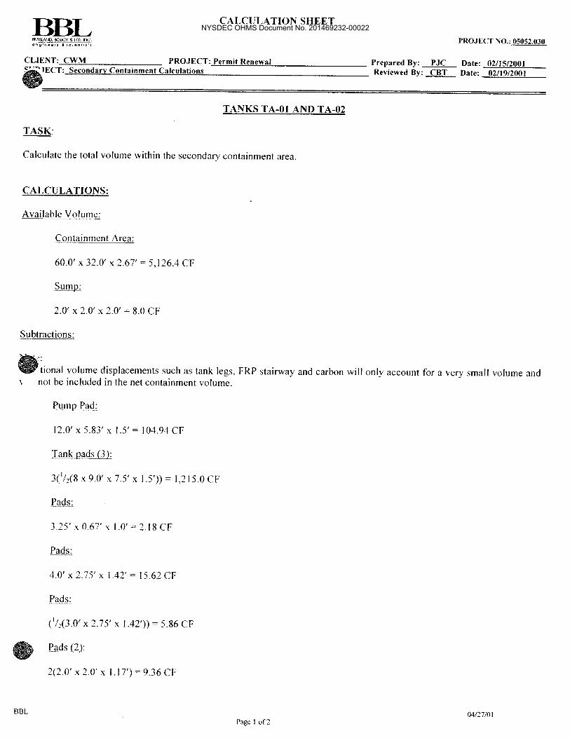
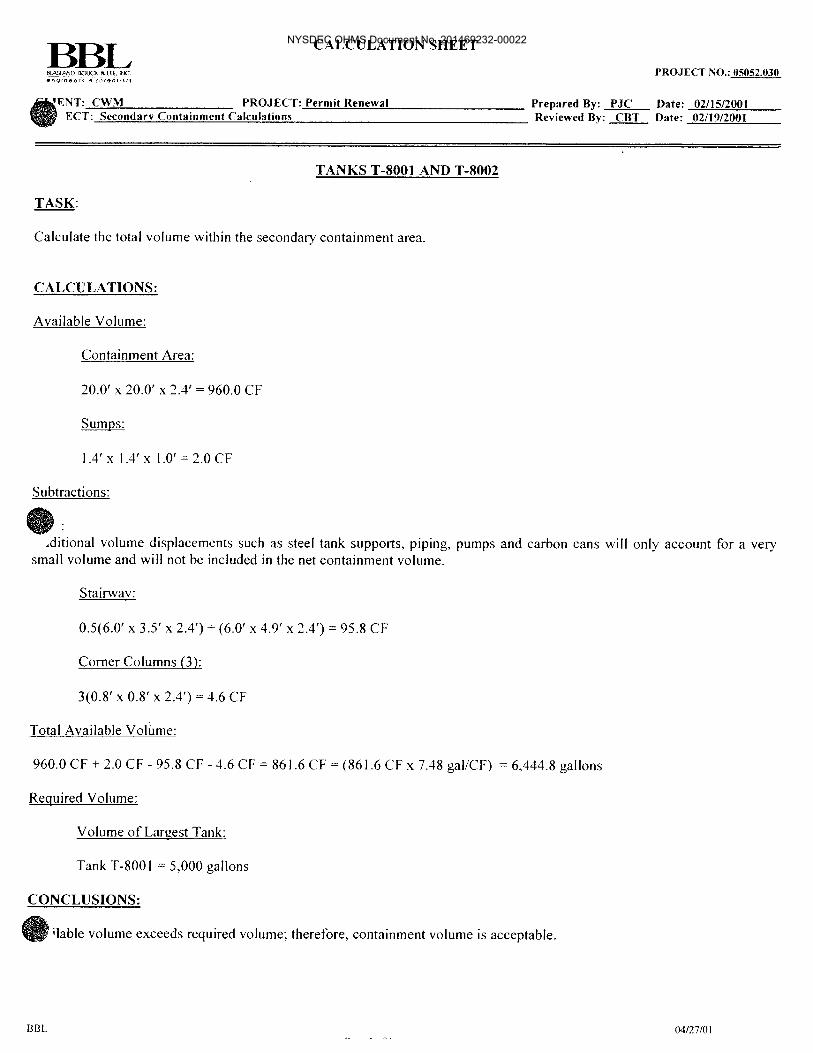
CALCULATION SHEET PAGE 1 OF 2
EnSol, Inc. Environmental Solutions PROJECT NO.: CLIENT: CWM Chemical Services LLC PROJECT: 13-7028 Prepared By: TAS Date: 8/13/13 SUBJECT: Water Treatment Building Secondary Containment Calculations Reviewed By: BDS Date: 8/13/13
X:\AAApj\CWM\13-7028 Sitewide Permit Sec Cont Calcs Updates (Task 9)\Water Treatment Bldg (Fig D-20)\13-7028 Sec Cont Calcs.doc 08/13/13
Page 1 of 2
WATER TREATMENT BUILDING TASK: Calculate the total volume within the secondary containment area. CALCULATIONS: Available Volume:
Containment Area:
34.5 x 34.8 x 1.83 = 2,197.1 CF
Trench: (29.9 x 1.0 x 0.8) + (31.1 x 1.3 x 0.1) = 27.9 CF Subtractions: Note: Additional volume displacements such as steel tank supports, FRP stairway, piping, and pumps will only account for a very small volume and will not be included in the net containment volume.
Tank Pad:
[(12.083 x 9.0) + 2(3.75 x 1.896) + 2(3.75 x 5.2083)] x 0.5 = 81.01 CF
Concrete pad:
6.3 x 2.5 x 0.3 = 4.73 CF
Stairway:
5.7 x 3.3 x 1.8 = 33.86 CF
4’-7” Tank:
x 2.292 x 1.8 = 29.65 CF 2’-4” Tank: x 1.172 x 1.8 = 7.74 CF Tank T-3007 and T-3008 Legs (8): 8(1.15 x 1.15 x 0.9) = 9.52 CF
NYSDEC OHMS Document No. 201469232-00022

CALCULATION SHEET PAGE 2 OF 2
EnSol, Inc. Environmental Solutions PROJECT NO.: CLIENT: CWM Chemical Services LLC PROJECT: 13-7028 Prepared By: TAS Date: 8/13/13 SUBJECT: Water Treatment Building Secondary Containment Calculations Reviewed By: BDS Date: 8/13/13
X:\AAApj\CWM\13-7028 Sitewide Permit Sec Cont Calcs Updates (Task 9)\Water Treatment Bldg (Fig D-20)\13-7028 Sec Cont Calcs.doc 08/13/13
Page 2 of 2
WATER TREATMENT BUILDING (continued)
Cartridge Filters (4): 4( x 0.542 x 1.5) = 5.50 CF
Wall Outcrop: (1/2(14.4 + 15.5) 0.4) x 1.8 = 10.76 CF
Total Available Volume: = 2,197.1 + 27.9 - 81.01 - 4.73 - 33.86 - 29.65 - 7.74 - 9.52 - 5.50 - 10.76 = 2,042.2 CF = (2,042.2 CF x 7.48 gal/CF) = 15,275.7 gallons Required Volume:
Volume of Largest Tank (Interconnected):
Tank T-3007 + Tank T-3008 = 15,200 gallons CONCLUSIONS: The available volume of secondary containment exceeds the volume of the largest tank (T-3007 and T-3008 interconnected).
NYSDEC OHMS Document No. 201469232-00022

NYSDEC OHMS Document No. 201469232-00022

NYSDEC OHMS Document No. 201469232-00022

NYSDEC OHMS Document No. 201469232-00022

NYSDEC OHMS Document No. 201469232-00022

NYSDEC OHMS Document No. 201469232-00022

NYSDEC OHMS Document No. 201469232-00022

NYSDEC OHMS Document No. 201469232-00022

NYSDEC OHMS Document No. 201469232-00022

NYSDEC OHMS Document No. 201469232-00022

NYSDEC OHMS Document No. 201469232-00022

NYSDEC OHMS Document No. 201469232-00022

NYSDEC OHMS Document No. 201469232-00022

NYSDEC OHMS Document No. 201469232-00022

NYSDEC OHMS Document No. 201469232-00022

NYSDEC OHMS Document No. 201469232-00022

NYSDEC OHMS Document No. 201469232-00022

NYSDEC OHMS Document No. 201469232-00022

NYSDEC OHMS Document No. 201469232-00022
NYSDEC OHMS Document No. 201469232-00022

NYSDEC OHMS Document No. 201469232-00022

NYSDEC OHMS Document No. 201469232-00022

NYSDEC OHMS Document No. 201469232-00022

NYSDEC OHMS Document No. 201469232-00022

NYSDEC OHMS Document No. 201469232-00022

NYSDEC OHMS Document No. 201469232-00022

NYSDEC OHMS Document No. 201469232-00022

NYSDEC OHMS Document No. 201469232-00022

NYSDEC OHMS Document No. 201469232-00022

NYSDEC OHMS Document No. 201469232-00022

NYSDEC OHMS Document No. 201469232-00022

NYSDEC OHMS Document No. 201469232-00022

NYSDEC OHMS Document No. 201469232-00022
NYSDEC OHMS Document No. 201469232-00022
NYSDEC OHMS Document No. 201469232-00022

NYSDEC OHMS Document No. 201469232-00022

NYSDEC OHMS Document No. 201469232-00022

NYSDEC OHMS Document No. 201469232-00022

NYSDEC OHMS Document No. 201469232-00022

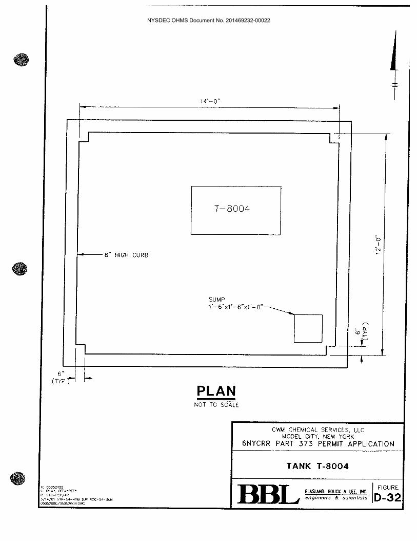
FIGURE D-34
TANK T-8009
NYSDEC OHMS Document No. 201469232-00022

NYSDEC OHMS Document No. 201469232-00022

CALCULATION SHEET PAGE 1 OF 2
EnSol, Inc. Environmental Solutions PROJECT NO.: 12-7009 CLIENT: CWM Chemical Services PROJECT: Site wide Permit Prepared By: CAC Date: 3/30/2012 SUBJECT: Secondary Containment Calculations Reviewed By: BDS Date: 3/30/2012
X:\AAApj\CWM\12-7009 Sitewide Permit Sec Cont Calcs (Task 11)\Tank T-8009 (Process Area IV)\Secondary Containment Calculations T-8009.doc 03/30/12
Page 1 of 2
PROCESS AREA IV TANK T-8009 TASK: Calculate the total volume within the secondary containment area. CALCULATIONS: Available Volume:
Containment Area:
8.0 x 6.5 x 1.5 = 78 CF Subtractions: Note: Additional minor volume displacements such as tank supports, FRP grating, piping etc., will only account for a very small volume and will not be included in the net containment volume. Total Available Volume: 78 CF x 7.48 gal/CF = 583 gallons
Required Volume:
Volume of Largest Tank: Tank T-8009 = 525 gallons
Net Difference
Tank T-8009 = 525 gallons Secondary Containment = 583 gallons Difference = +58 gallons CONCLUSIONS: Available volume exceeds required volume; therefore, containment volume is acceptable.
NYSDEC OHMS Document No. 201469232-00022

FIGURE D-35
TANK T-8010
NYSDEC OHMS Document No. 201469232-00022

NYSDEC OHMS Document No. 201469232-00022

CALCULATION SHEET PAGE 1 OF 2
EnSol, Inc. Environmental Solutions PROJECT NO.: 12-7009 CLIENT: CWM Chemical Services PROJECT: Site wide Permit Prepared By: CAC Date: 3/30/2012 SUBJECT: Secondary Containment Calculations Reviewed By: BDS Date: 3/30/2012
X:\AAApj\CWM\12-7009 Sitewide Permit Sec Cont Calcs (Task 11)\Tank T-8010 (Process Area III)\Secondary Containment Calculations T-8010.doc 03/30/12
Page 1 of 2
PROCESS AREA III TANK T-8010 TASK: Calculate the total volume within the secondary containment area. CALCULATIONS: Available Volume:
Containment Area:
7.5 x 13.5 x 1.8 = 182.2 CF Subtractions: -8.45 CF for baffles within the secondary containment structure. Note: Additional minor volume displacements such as tank supports, FRP grating, piping etc., will only account for a very small volume and will not be included in the net containment volume. Total Available Volume: 173.8 CF x 7.48 gal/CF = 1300 gallons
Required Volume:
Volume of Largest Tank: Tank T-8010 = 1000 gallons
Net Difference
Tank T-8010 = 1000 gallons Secondary Containment = 1300 gallons
Difference = +300 gallons CONCLUSIONS: Available volume exceeds required volume; therefore, containment volume is acceptable.
NYSDEC OHMS Document No. 201469232-00022

FIGURE D-36
TANK T-9001
NYSDEC OHMS Document No. 201469232-00022
NYSDEC OHMS Document No. 201469232-00022