Embed Size (px)
Citation preview

Appendix C
NOI and DEC
Acknowledgement Letter
Fax (Owner/Operator)
- -
Page 1 of 14
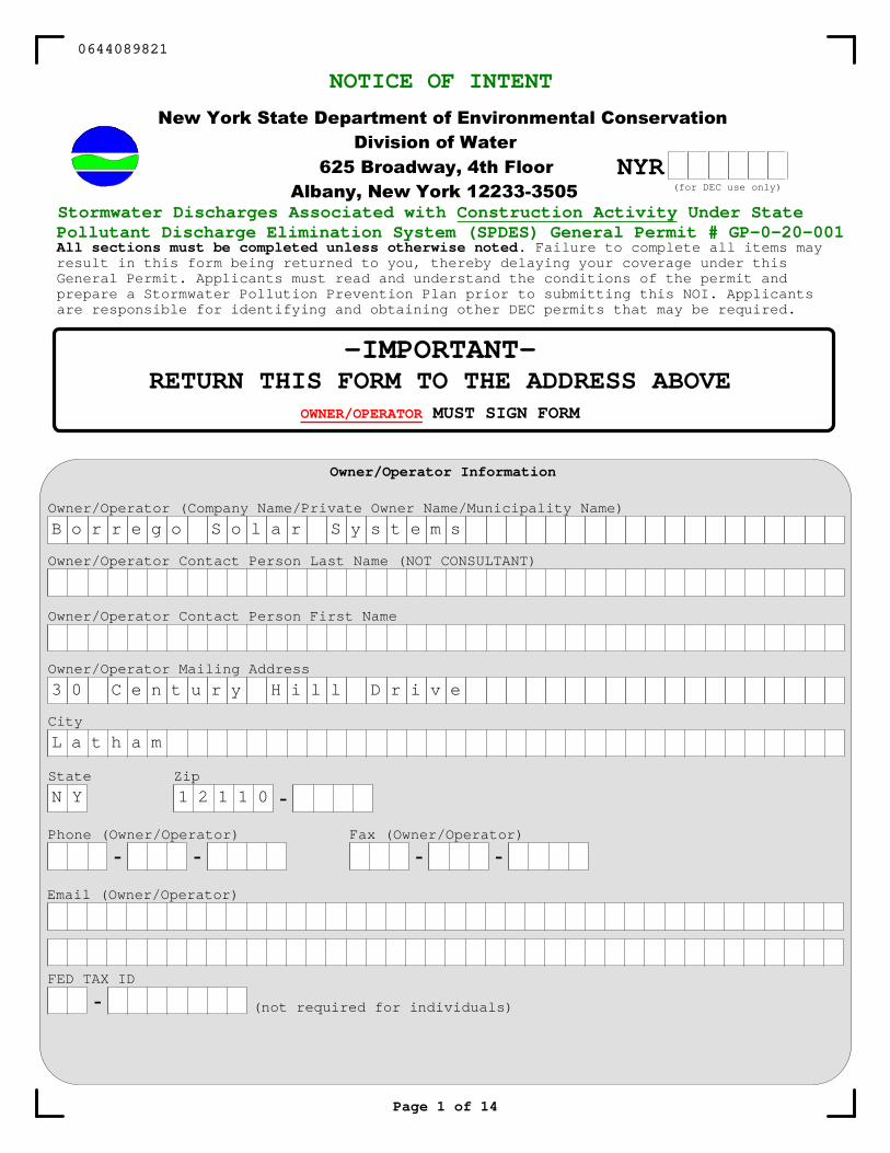
New York State Department of Environmental Conservation
Division of Water
625 Broadway, 4th Floor
Albany, New York 12233-3505
NOTICE OF INTENT
-IMPORTANT-RETURN THIS FORM TO THE ADDRESS ABOVE
OWNER/OPERATOR MUST SIGN FORM
Stormwater Discharges Associated with Construction Activity Under StatePollutant Discharge Elimination System (SPDES) General Permit # GP-0-20-001All sections must be completed unless otherwise noted. Failure to complete all items may result in this form being returned to you, thereby delaying your coverage under thisGeneral Permit. Applicants must read and understand the conditions of the permit andprepare a Stormwater Pollution Prevention Plan prior to submitting this NOI. Applicantsare responsible for identifying and obtaining other DEC permits that may be required.
Owner/Operator Information
Owner/Operator Contact Person Last Name (NOT CONSULTANT)
Owner/Operator Contact Person First Name
Owner/Operator Mailing Address
City
State Zip
-
Phone (Owner/Operator)
- -
Email (Owner/Operator)
Owner/Operator (Company Name/Private Owner Name/Municipality Name)
NYR(for DEC use only)
FED TAX ID
- (not required for individuals)
0644089821
B o r r e g o S o l a r S y s t e m s
3 0 C e n t u r y H i l l D r i v e
L a t h a m
N Y 1 2 1 1 0
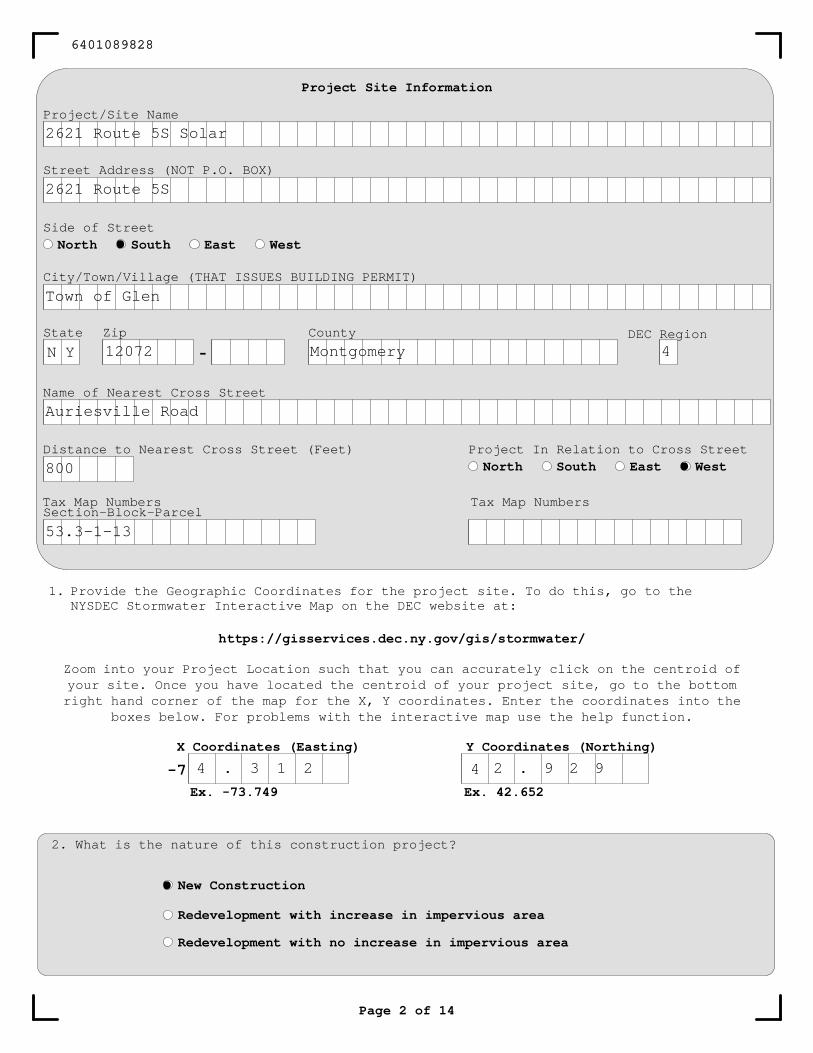
1. Provide the Geographic Coordinates for the project site. To do this, go to theNYSDEC Stormwater Interactive Map on the DEC website at:
https://gisservices.dec.ny.gov/gis/stormwater/
Zoom into your Project Location such that you can accurately click on the centroid ofyour site. Once you have located the centroid of your project site, go to the bottom right hand corner of the map for the X, Y coordinates. Enter the coordinates into the
boxes below. For problems with the interactive map use the help function.
X Coordinates (Easting) Y Coordinates (Northing)
Project Site Information
Project/Site Name
Street Address (NOT P.O. BOX)
City/Town/Village (THAT ISSUES BUILDING PERMIT)
State Zip
-County
Name of Nearest Cross Street
Distance to Nearest Cross Street (Feet) Project In Relation to Cross Street
North South East West
Page 2 of 14
2. What is the nature of this construction project?
New Construction
Redevelopment with increase in impervious area
Redevelopment with no increase in impervious area
Section-Block-ParcelTax Map Numbers
Side of Street
North South East West
DEC Region
Tax Map Numbers
6401089828
Ex. -73.749 Ex. 42.652
-7
2621 Route 5S Solar
2621 Route 5S
Town of Glen
N Y 12072 Montgomery 4
Auriesville Road
800
53.3-1-13
4 . 3 1 2 4 2 . 9 2 9
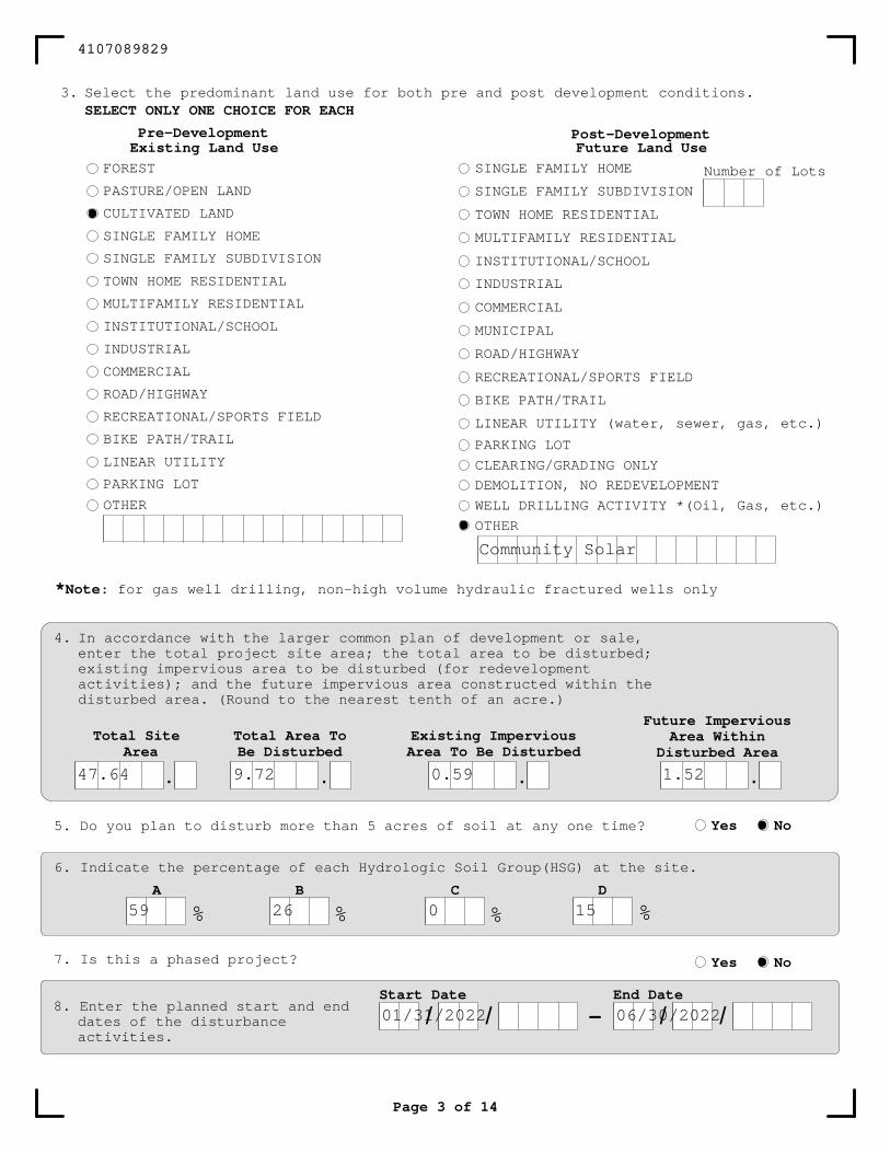
3. Select the predominant land use for both pre and post development conditions.SELECT ONLY ONE CHOICE FOR EACH
Page 3 of 14
Existing Land Use
FOREST
PASTURE/OPEN LAND
CULTIVATED LAND
SINGLE FAMILY HOME
SINGLE FAMILY SUBDIVISION
TOWN HOME RESIDENTIAL
MULTIFAMILY RESIDENTIAL
INSTITUTIONAL/SCHOOL
INDUSTRIAL
COMMERCIAL
ROAD/HIGHWAY
RECREATIONAL/SPORTS FIELD
BIKE PATH/TRAIL
LINEAR UTILITY
PARKING LOT
OTHER
Future Land Use
SINGLE FAMILY HOME
SINGLE FAMILY SUBDIVISION
TOWN HOME RESIDENTIAL
MULTIFAMILY RESIDENTIAL
INSTITUTIONAL/SCHOOL
INDUSTRIAL
COMMERCIAL
MUNICIPAL
ROAD/HIGHWAY
RECREATIONAL/SPORTS FIELD
BIKE PATH/TRAIL
LINEAR UTILITY (water, sewer, gas, etc.)
PARKING LOT
CLEARING/GRADING ONLY
DEMOLITION, NO REDEVELOPMENT
WELL DRILLING ACTIVITY *(Oil, Gas, etc.)
OTHER
Pre-Development Post-Development
4. In accordance with the larger common plan of development or sale,enter the total project site area; the total area to be disturbed;existing impervious area to be disturbed (for redevelopmentactivities); and the future impervious area constructed within thedisturbed area. (Round to the nearest tenth of an acre.)
Number of Lots
*Note: for gas well drilling, non-high volume hydraulic fractured wells only
Total SiteArea
.
Total Area ToBe Disturbed
.
Existing ImperviousArea To Be Disturbed
.
Future ImperviousArea Within
Disturbed Area
.
5. Do you plan to disturb more than 5 acres of soil at any one time? Yes No
6. Indicate the percentage of each Hydrologic Soil Group(HSG) at the site.
A B C D
% % % %
7. Is this a phased project? Yes No
8. Enter the planned start and enddates of the disturbanceactivities.
-Start Date
/ /End Date
/ /
4107089829
Community Solar
47.64 9.72 0.59 1.52
59 26 0 15
01/31/2022 06/30/2022
Page 4 of 14
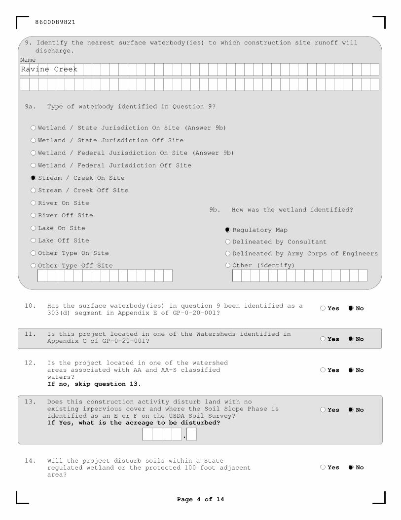
Name
9. Identify the nearest surface waterbody(ies) to which construction site runoff willdischarge.
9a. Type of waterbody identified in Question 9?
Wetland / State Jurisdiction On Site (Answer 9b)
Wetland / State Jurisdiction Off Site
Wetland / Federal Jurisdiction On Site (Answer 9b)
Wetland / Federal Jurisdiction Off Site
Stream / Creek On Site
Stream / Creek Off Site
River On Site
River Off Site
Lake On Site
Lake Off Site
Other Type On Site
Other Type Off Site
9b. How was the wetland identified?
Regulatory Map
Delineated by Consultant
Delineated by Army Corps of Engineers
Other (identify)
Yes No
Yes No
Yes No
10. Has the surface waterbody(ies) in question 9 been identified as a 303(d) segment in Appendix E of GP-0-20-001?
11. Is this project located in one of the Watersheds identified in Appendix C of GP-0-20-001?
12. Is the project located in one of the watershedareas associated with AA and AA-S classifiedwaters?If no, skip question 13.
13. Does this construction activity disturb land with noexisting impervious cover and where the Soil Slope Phase is identified as an E or F on the USDA Soil Survey?If Yes, what is the acreage to be disturbed?
Yes No
.
14. Will the project disturb soils within a Stateregulated wetland or the protected 100 foot adjacentarea?
Yes No
8600089821
Ravine Creek
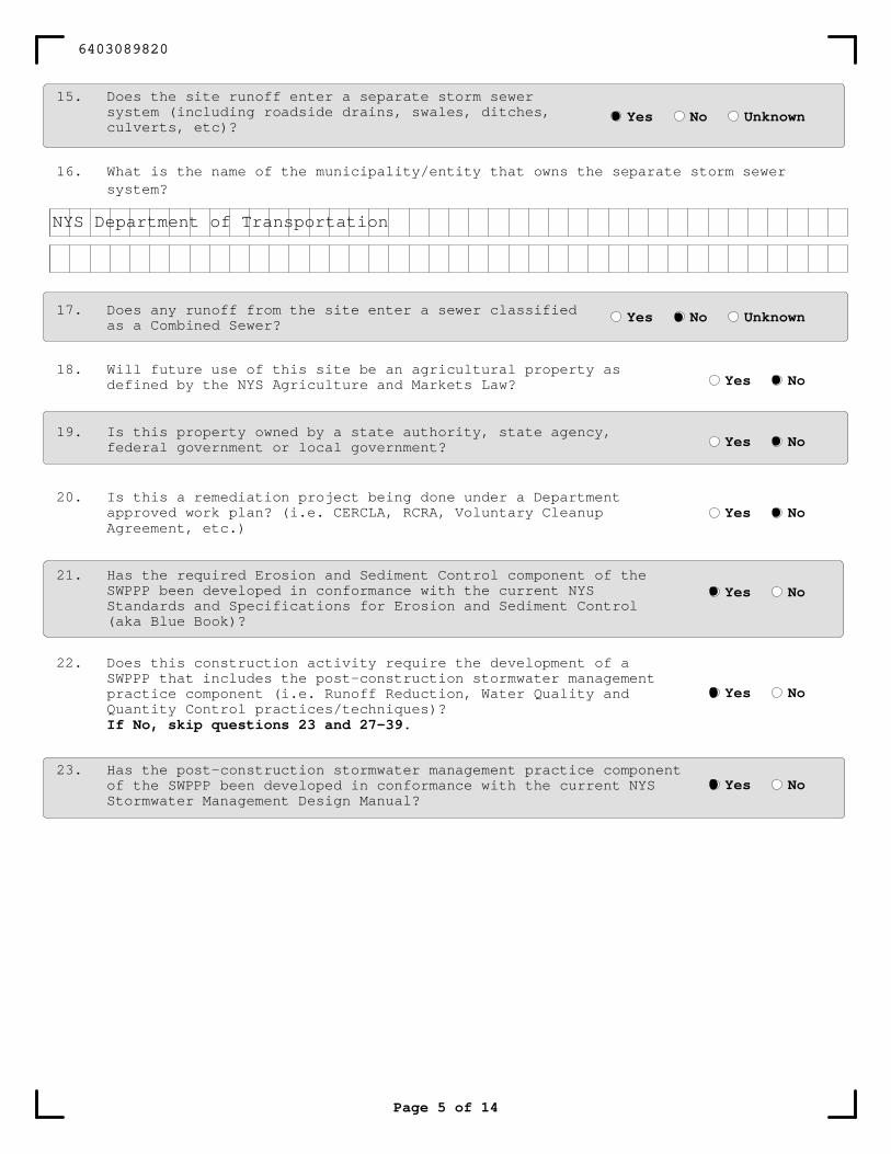
15. Does the site runoff enter a separate storm sewersystem (including roadside drains, swales, ditches,culverts, etc)?
16. What is the name of the municipality/entity that owns the separate storm sewersystem?
Yes No Unknown
17. Does any runoff from the site enter a sewer classifiedas a Combined Sewer?
Yes No Unknown
21. Has the required Erosion and Sediment Control component of theSWPPP been developed in conformance with the current NYSStandards and Specifications for Erosion and Sediment Control(aka Blue Book)?
22. Does this construction activity require the development of aSWPPP that includes the post-construction stormwater managementpractice component (i.e. Runoff Reduction, Water Quality andQuantity Control practices/techniques)?If No, skip questions 23 and 27-39.
23. Has the post-construction stormwater management practice componentof the SWPPP been developed in conformance with the current NYSStormwater Management Design Manual?
Yes No
Yes No
Yes No
Page 5 of 14
18. Will future use of this site be an agricultural property asdefined by the NYS Agriculture and Markets Law? Yes No
Yes No20. Is this a remediation project being done under a Department
approved work plan? (i.e. CERCLA, RCRA, Voluntary CleanupAgreement, etc.)
Yes No19. Is this property owned by a state authority, state agency,
federal government or local government?
6403089820
NYS Department of Transportation
Page 6 of 14
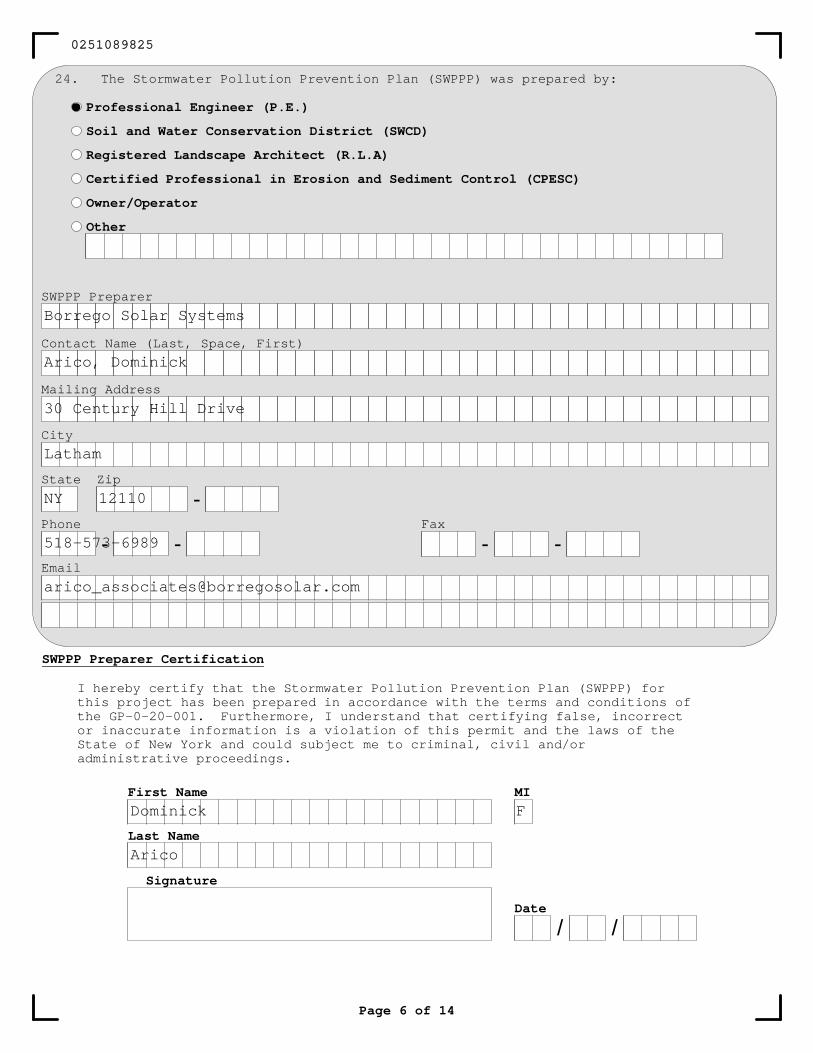
SWPPP Preparer
Contact Name (Last, Space, First)
Mailing Address
City
State Zip
-Phone
- -Fax
Signature
Date
/ /
First Name
Last Name
MI
SWPPP Preparer Certification
24. The Stormwater Pollution Prevention Plan (SWPPP) was prepared by:
Professional Engineer (P.E.)
Soil and Water Conservation District (SWCD)
Registered Landscape Architect (R.L.A)
Certified Professional in Erosion and Sediment Control (CPESC)
Owner/Operator
Other
I hereby certify that the Stormwater Pollution Prevention Plan (SWPPP) for this project has been prepared in accordance with the terms and conditions of the GP-0-20-001. Furthermore, I understand that certifying false, incorrect or inaccurate information is a violation of this permit and the laws of the State of New York and could subject me to criminal, civil and/or administrative proceedings.
0251089825
Borrego Solar Systems
Arico, Dominick
30 Century Hill Drive
Latham
NY 12110
518-573-6989
Dominick F
Arico
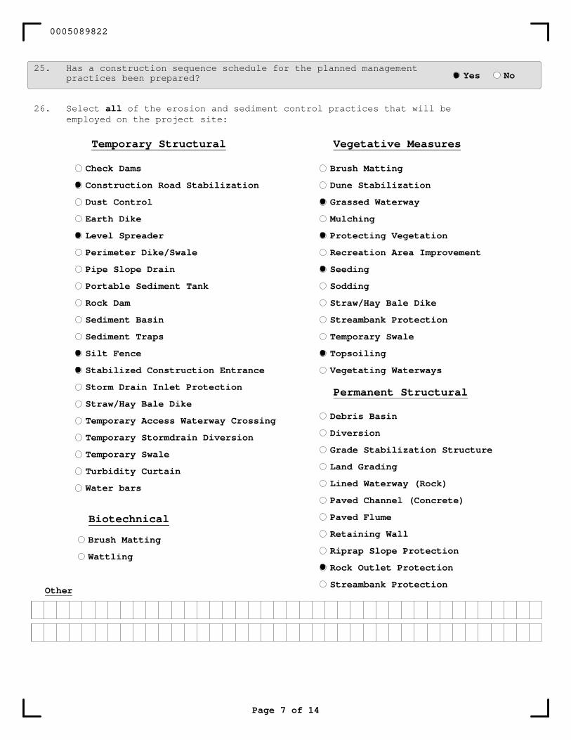
26. Select all of the erosion and sediment control practices that will beemployed on the project site:
Page 7 of 14
Biotechnical
Brush Matting
Wattling
Other
25. Has a construction sequence schedule for the planned managementpractices been prepared? Yes No
Brush Matting
Dune Stabilization
Grassed Waterway
Mulching
Protecting Vegetation
Recreation Area Improvement
Seeding
Sodding
Straw/Hay Bale Dike
Streambank Protection
Temporary Swale
Topsoiling
Vegetating Waterways
Vegetative Measures
Check Dams
Construction Road Stabilization
Dust Control
Earth Dike
Level Spreader
Perimeter Dike/Swale
Pipe Slope Drain
Portable Sediment Tank
Rock Dam
Sediment Basin
Sediment Traps
Silt Fence
Stabilized Construction Entrance
Storm Drain Inlet Protection
Straw/Hay Bale Dike
Temporary Access Waterway Crossing
Temporary Stormdrain Diversion
Temporary Swale
Turbidity Curtain
Water bars
Temporary Structural
Debris Basin
Diversion
Grade Stabilization Structure
Land Grading
Lined Waterway (Rock)
Paved Channel (Concrete)
Paved Flume
Retaining Wall
Riprap Slope Protection
Rock Outlet Protection
Streambank Protection
Permanent Structural
0005089822
Page 8 of 14
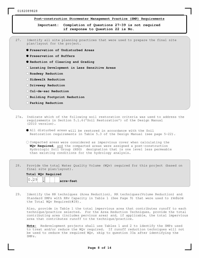
Post-construction Stormwater Management Practice (SMP) Requirements
Important: Completion of Questions 27-39 is not requiredif response to Question 22 is No.
27. Identify all site planning practices that were used to prepare the final siteplan/layout for the project.
Preservation of Undisturbed Areas
Preservation of Buffers
Reduction of Clearing and Grading
Locating Development in Less Sensitive Areas
Roadway Reduction
Sidewalk Reduction
Driveway Reduction
Cul-de-sac Reduction
Building Footprint Reduction
Parking Reduction
28. Provide the total Water Quality Volume (WQv) required for this project (based onfinal site plan/layout).
Total WQv Required
. acre-feet
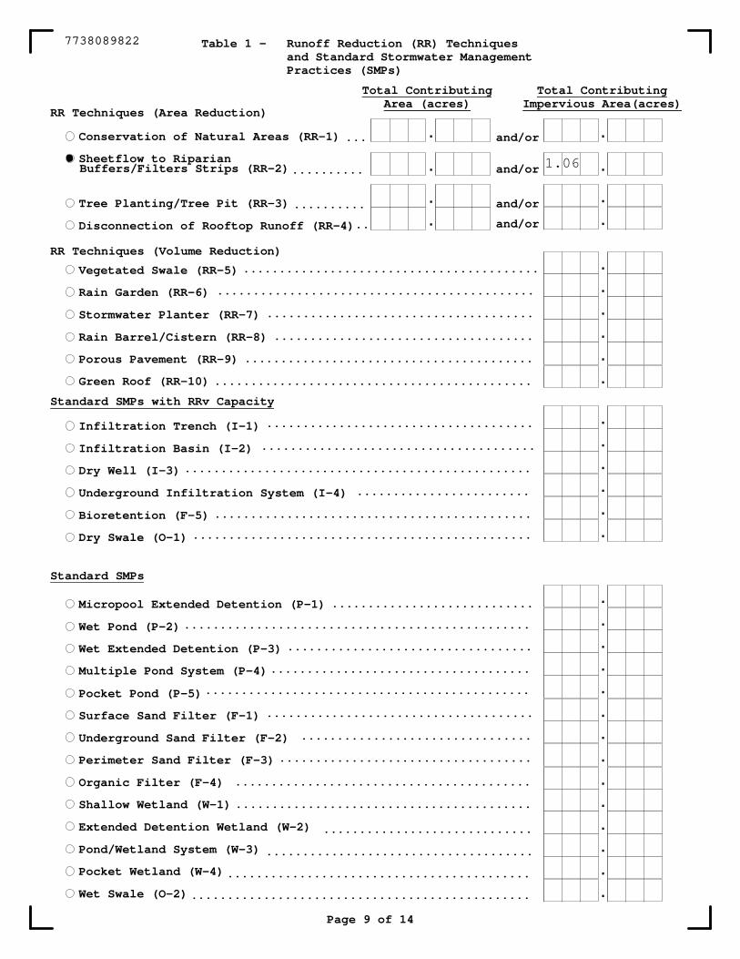
29. Identify the RR techniques (Area Reduction), RR techniques(Volume Reduction) andStandard SMPs with RRv Capacity in Table 1 (See Page 9) that were used to reducethe Total WQv Required(#28).
Also, provide in Table 1 the total impervious area that contributes runoff to eachtechnique/practice selected. For the Area Reduction Techniques, provide the totalcontributing area (includes pervious area) and, if applicable, the total imperviousarea that contributes runoff to the technique/practice.
Note: Redevelopment projects shall use Tables 1 and 2 to identify the SMPs usedto treat and/or reduce the WQv required. If runoff reduction techniques will notbe used to reduce the required WQv, skip to question 33a after identifying theSMPs.
27a. Indicate which of the following soil restoration criteria was used to address therequirements in Section 5.1.6("Soil Restoration") of the Design Manual(2010 version).
All disturbed areas
Compacted areas
will be restored in accordance with the SoilRestoration requirements in Table 5.3 of the Design Manual (see page 5-22).
were considered as impervious cover when calculating theWQv Required, and the compacted areas were assigned a post-constructionHydrologic Soil Group (HSG) designation that is one level less permeablethan existing conditions for the hydrology analysis.
0182089828
0.29
and/or
and/or
and/or
and/or
Conservation of Natural Areas (RR-1)
Sheetflow to Riparian
Tree Planting/Tree Pit (RR-3)
Disconnection of Rooftop Runoff (RR-4)
Vegetated Swale (RR-5)
Rain Garden (RR-6)
Stormwater Planter (RR-7)
Rain Barrel/Cistern (RR-8)
Porous Pavement (RR-9)
Green Roof (RR-10)
Infiltration Trench (I-1)
Infiltration Basin (I-2)
Dry Well (I-3)
Underground Infiltration System (I-4)
Bioretention (F-5)
Dry Swale (O-1)
Micropool Extended Detention (P-1)
Wet Pond (P-2)
Wet Extended Detention (P-3)
Multiple Pond System (P-4)
Pocket Pond (P-5)
Surface Sand Filter (F-1)
Underground Sand Filter (F-2)
Perimeter Sand Filter (F-3)
Organic Filter (F-4)
Shallow Wetland (W-1)
Extended Detention Wetland (W-2)
Pond/Wetland System (W-3)
Pocket Wetland (W-4)
Wet Swale (O-2)
.
.
.
.
.
.
.
.
.
.
.
.
.
.
............................
..................................
....................................
.............................................
.....................................
................................
...................................
.........................................
.........................................
.............................
..................................................
..........................................
...............................................
................................................
RR Techniques (Area Reduction)
Total ContributingImpervious Area(acres)
.
.
.
.
.
.
.
.
.
.
.
.
.
.
.
...
..........
..........
..
.........................................
............................................
.....................................
....................................
........................................
.....................................
......................................
................................................
........................
............................................
...............................................
Table 1 - Runoff Reduction (RR) Techniquesand Standard Stormwater ManagementPractices (SMPs)
RR Techniques (Volume Reduction)
Standard SMPs with RRv Capacity
Standard SMPs
Page 9 of 14
Total ContributingArea (acres)
.
.
.
.
Buffers/Filters Strips (RR-2)
.............................................
7738089822
1.06
.
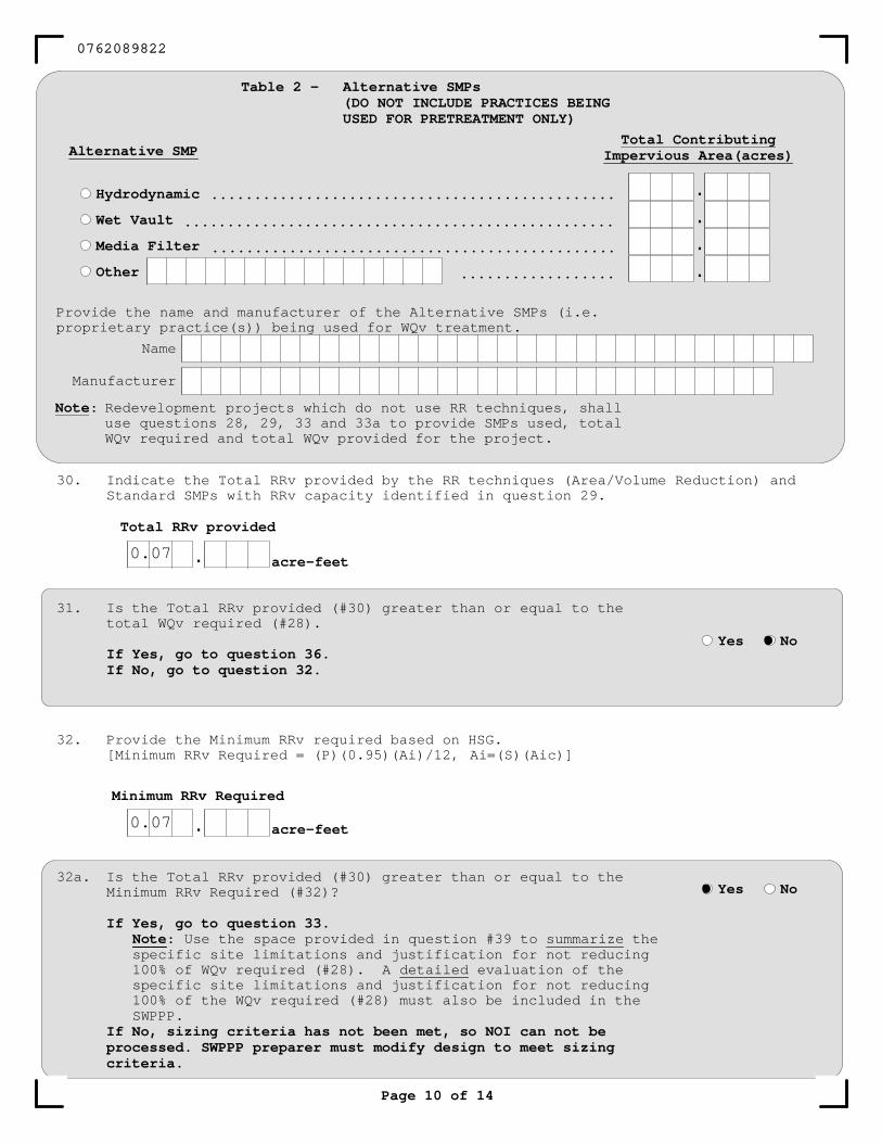
31. Is the Total RRv provided (#30) greater than or equal to thetotal WQv required (#28).
If Yes, go to question 36.If No, go to question 32.
Yes No
Total RRv provided
32. Provide the Minimum RRv required based on HSG.[Minimum RRv Required = (P)(0.95)(Ai)/12, Ai=(S)(Aic)]
Minimum RRv Required
. acre-feet
30. Indicate the Total RRv provided by the RR techniques (Area/Volume Reduction) andStandard SMPs with RRv capacity identified in question 29.
acre-feet
32a. Is the Total RRv provided (#30) greater than or equal to theMinimum RRv Required (#32)?
If Yes, go to question 33.Note: Use the space provided in question #39 to summarize thespecific site limitations and justification for not reducing100% of WQv required (#28). A detailed evaluation of thespecific site limitations and justification for not reducing100% of the WQv required (#28) must also be included in theSWPPP.
If No, sizing criteria has not been met, so NOI can not beprocessed. SWPPP preparer must modify design to meet sizingcriteria.
Yes No
Page 10 of 14
Hydrodynamic
Wet Vault
Media Filter
Other
Alternative SMP
.
.
.
.
...............................................
..................................................
...............................................
..................
Table 2 - Alternative SMPs(DO NOT INCLUDE PRACTICES BEINGUSED FOR PRETREATMENT ONLY)
Note: Redevelopment projects which do not use RR techniques, shalluse questions 28, 29, 33 and 33a to provide SMPs used, totalWQv required and total WQv provided for the project.
Total ContributingImpervious Area(acres)
Provide the name and manufacturer of the Alternative SMPs (i.e.proprietary practice(s)) being used for WQv treatment.
Name
Manufacturer
0762089822
0.07
0.07
. acre-feet
CPv Provided
acre-feet.CPv Required
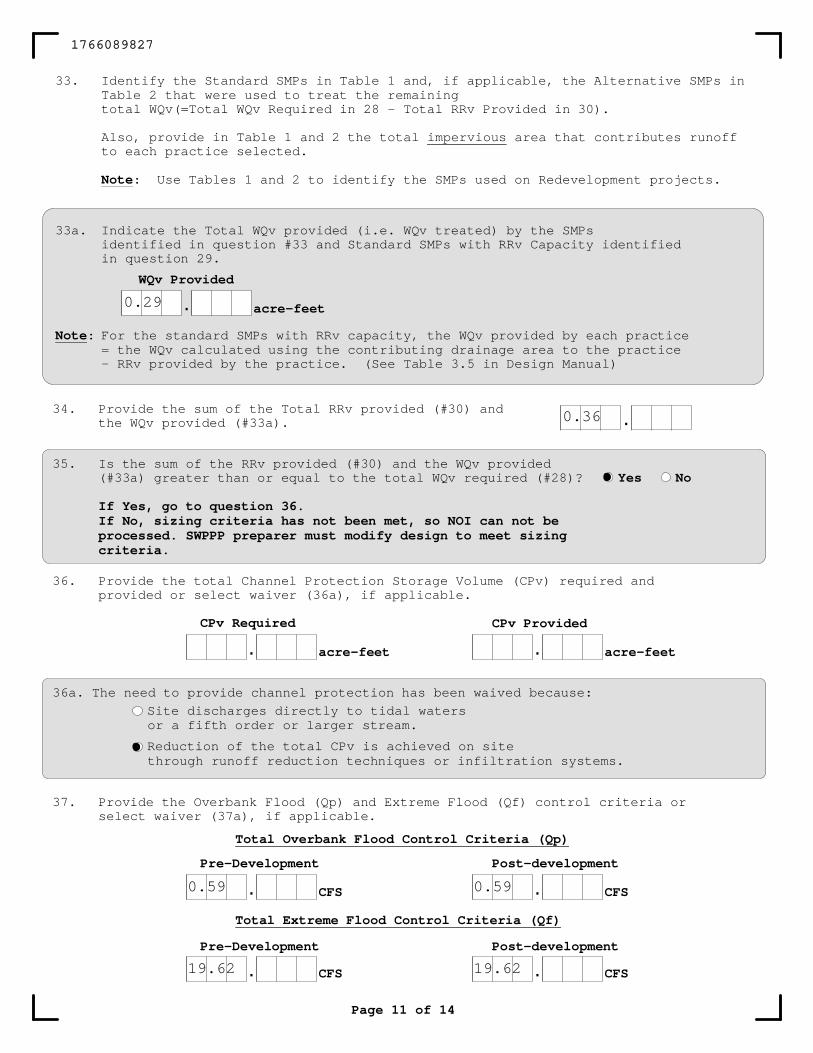
36. Provide the total Channel Protection Storage Volume (CPv) required andprovided or select waiver (36a), if applicable.
Page 11 of 14
35. Is the sum of the RRv provided (#30) and the WQv provided(#33a) greater than or equal to the total WQv required (#28)?
If Yes, go to question 36.If No, sizing criteria has not been met, so NOI can not beprocessed. SWPPP preparer must modify design to meet sizingcriteria.
.34. Provide the sum of the Total RRv provided (#30) and
the WQv provided (#33a).
Yes No
33a. Indicate the Total WQv provided (i.e. WQv treated) by the SMPsidentified in question #33 and Standard SMPs with RRv Capacity identifiedin question 29.
.WQv Provided
acre-feet
Note: For the standard SMPs with RRv capacity, the WQv provided by each practice= the WQv calculated using the contributing drainage area to the practice- RRv provided by the practice. (See Table 3.5 in Design Manual)
33. Identify the Standard SMPs in Table 1 and, if applicable, the Alternative SMPs inTable 2 that were used to treat the remainingtotal WQv(=Total WQv Required in 28 - Total RRv Provided in 30).
Also, provide in Table 1 and 2 the total impervious area that contributes runoffto each practice selected.
Note: Use Tables 1 and 2 to identify the SMPs used on Redevelopment projects.
Site discharges directly to tidal waters
Reduction of the total CPv is achieved on site
36a. The need to provide channel protection has been waived because:
or a fifth order or larger stream.
through runoff reduction techniques or infiltration systems.
. CFS CFS.Post-developmentPre-Development
Total Extreme Flood Control Criteria (Qf)
. CFS . CFS
Post-developmentPre-Development
Total Overbank Flood Control Criteria (Qp)
37. Provide the Overbank Flood (Qp) and Extreme Flood (Qf) control criteria orselect waiver (37a), if applicable.
1766089827
0.29
0.36
0.59 0.59
19.62 19.62
Page 12 of 14
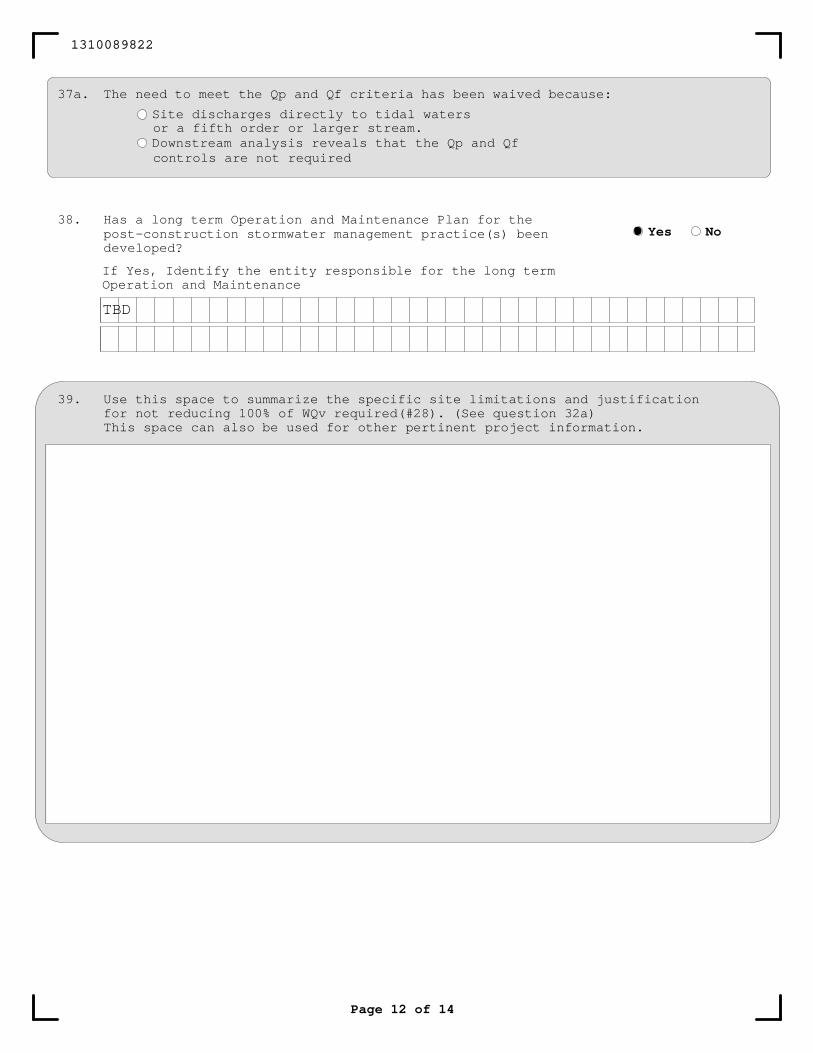
39. Use this space to summarize the specific site limitations and justificationfor not reducing 100% of WQv required(#28). (See question 32a)This space can also be used for other pertinent project information.
38. Has a long term Operation and Maintenance Plan for thepost-construction stormwater management practice(s) beendeveloped?
If Yes, Identify the entity responsible for the long termOperation and Maintenance
Yes No
37a. The need to meet the Qp and Qf criteria has been waived because:
Site discharges directly to tidal waters
Downstream analysis reveals that the Qp and Qfcontrols are not required
or a fifth order or larger stream.
1310089822
TBD
Air Pollution Control
Coastal Erosion
Hazardous Waste
Long Island Wells
Mined Land Reclamation
Solid Waste
Navigable Waters Protection / Article 15
Water Quality Certificate
Dam Safety
Water Supply
Freshwater Wetlands/Article 24
Tidal Wetlands
Wild, Scenic and Recreational Rivers
Stream Bed or Bank Protection / Article 15
Endangered or Threatened Species(Incidental Take Permit)
Individual SPDES
SPDES Multi-Sector GP
Other
None
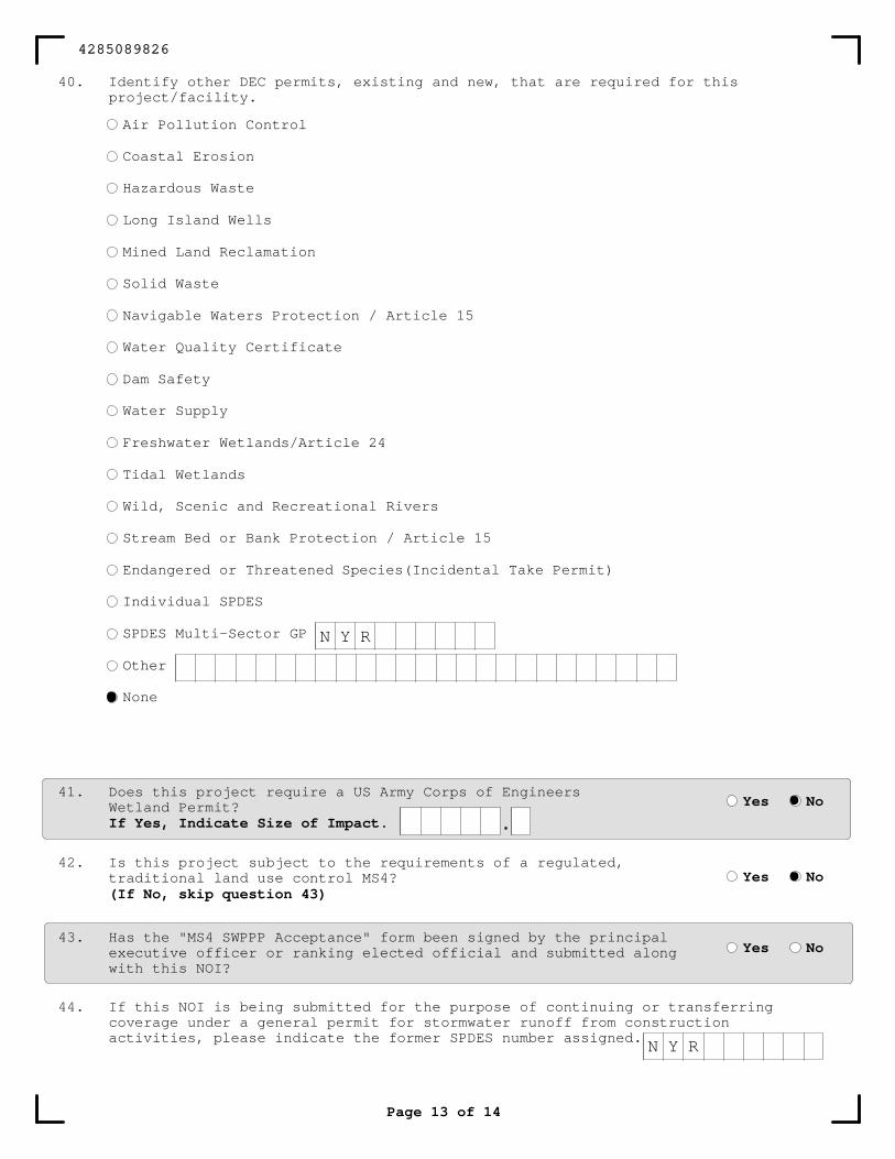
44. If this NOI is being submitted for the purpose of continuing or transferringcoverage under a general permit for stormwater runoff from constructionactivities, please indicate the former SPDES number assigned.
42. Is this project subject to the requirements of a regulated,traditional land use control MS4?(If No, skip question 43)
Yes No
43. Has the "MS4 SWPPP Acceptance" form been signed by the principalexecutive officer or ranking elected official and submitted alongwith this NOI?
Yes No
41. Does this project require a US Army Corps of EngineersWetland Permit?If Yes, Indicate Size of Impact.
Yes No
.
Page 13 of 14
40. Identify other DEC permits, existing and new, that are required for thisproject/facility.
4285089826
N Y R
N Y R
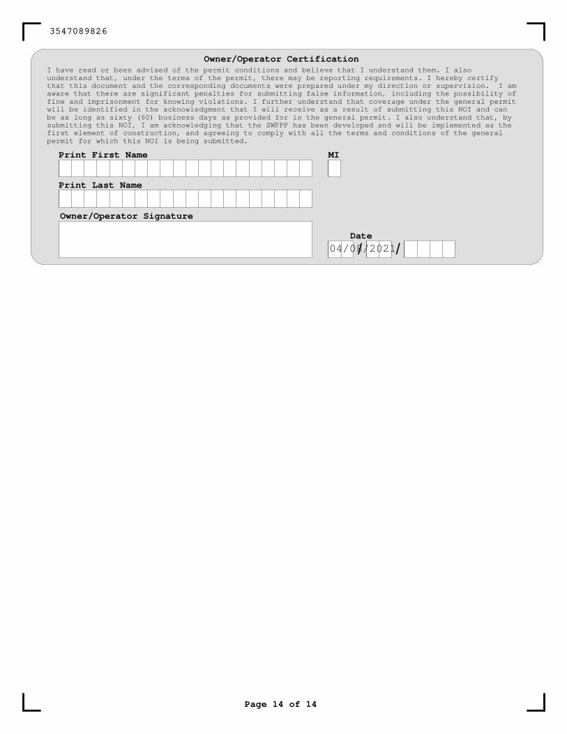
Owner/Operator CertificationI have read or been advised of the permit conditions and believe that I understand them. I alsounderstand that, under the terms of the permit, there may be reporting requirements. I hereby certifythat this document and the corresponding documents were prepared under my direction or supervision. I amaware that there are significant penalties for submitting false information, including the possibility offine and imprisonment for knowing violations. I further understand that coverage under the general permitwill be identified in the acknowledgment that I will receive as a result of submitting this NOI and canbe as long as sixty (60) business days as provided for in the general permit. I also understand that, bysubmitting this NOI, I am acknowledging that the SWPPP has been developed and will be implemented as thefirst element of construction, and agreeing to comply with all the terms and conditions of the generalpermit for which this NOI is being submitted.
Owner/Operator Signature
Date
/ /
Print First Name
Print Last Name
MI
Page 14 of 14
3547089826
04/08/2021
08982TFRMValueDefTFRMValueDef16808982TFRMAmp & <

Appendix D
Blank NOT Form
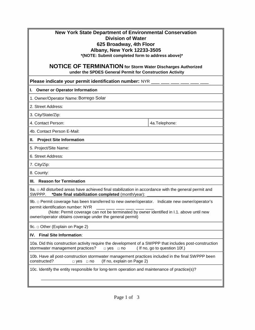
New York State Department of Environmental Conservation Division of Water
625 Broadway, 4th Floor Albany, New York 12233-3505
*(NOTE: Submit completed form to address above)*
NOTICE OF TERMINATION for Storm Water Discharges Authorizedunder the SPDES General Permit for Construction Activity
Please indicate your permit identification number: NYR ___ ___ ___ ___ ___ ___
I. Owner or Operator Information 1. Owner/Operator Name:
2. Street Address:
3. City/State/Zip:
4. Contact Person: 4a.Telephone:
4b. Contact Person E-Mail:
II. Project Site Information
5. Project/Site Name:
6. Street Address:
7. City/Zip:
8. County:
III. Reason for Termination
9a. □ All disturbed areas have achieved final stabilization in accordance with the general permit and SWPPP. *Date final stabilization completed (month/year):
9b. □ Permit coverage has been transferred to new owner/operator. Indicate new owner/operator’s permit identification number: NYR ___ ___ ___ ___ ___ ___
(Note: Permit coverage can not be terminated by owner identified in I.1. above until new owner/operator obtains coverage under the general permit)
9c. □ Other (Explain on Page 2)
IV. Final Site Information:
10a. Did this construction activity require the development of a SWPPP that includes post-constructionstormwater management practices? □ yes □ no ( If no, go to question 10f.)
10b. Have all post-construction stormwater management practices included in the final SWPPP been constructed? □ yes □ no (If no, explain on Page 2)
10c. Identify the entity responsible for long-term operation and maintenance of practice(s)?
Page 1 of 3
Borrego Solar
NOTICE OF TERMINATION for Storm Water Discharges Authorized under theSPDES General Permit for Construction Activity - continued
10d. Has the entity responsible for long-term operation and maintenance been given a copy of theoperation and maintenance plan required by the general permit? □ yes □ no
10e. Indicate the method used to ensure long-term operation and maintenance of the post-construction stormwater management practice(s):
□ Post-construction stormwater management practice(s) and any right-of-way(s) needed tomaintain practice(s) have been deeded to the municipality.
□ Executed maintenance agreement is in place with the municipality that will maintain thepost-construction stormwater management practice(s).
□ For post-construction stormwater management practices that are privately owned, a mechanismis in place that requires operation and maintenance of the practice(s) in accordance with the operation and maintenance plan, such as a deed covenant in the owner or operator’s deed of record.
□ For post-construction stormwater management practices that are owned by a public or privateinstitution (e.g. school, university or hospital), government agency or authority, or public utility; policy and procedures are in place that ensures operation and maintenance of the practice(s) in accordance with the operation and maintenance plan.
10f. Provide the total area of impervious surface (i.e. roof, pavement, concrete, gravel, etc.) constructed within the disturbance area? (acres)
11. Is this project subject to the requirements of a regulated, traditional land use control MS4? □ yes□ no (If Yes, complete section VI - “MS4 Acceptance” statement
V. Additional Information/Explanation: (Use this section to answer questions 9c. and 10b., if applicable)
VI. MS4 Acceptance - MS4 Official (principal executive officer or ranking elected official) or DulyAuthorized Representative (Note: Not required when 9b. is checked -transfer of coverage)
I have determined that it is acceptable for the owner or operator of the construction project identified in question 5 to submit the Notice of Termination at this time.
Printed Name:
Title/Position:
Signature: Date:
Page 2 of 3
NOTICE OF TERMINATION for Storm Water Discharges Authorized under theSPDES General Permit for Construction Activity - continued
VII. Qualified Inspector Certification - Final Stabilization:
I hereby certify that all disturbed areas have achieved final stabilization as defined in the current version of the general permit, and that all temporary, structural erosion and sediment control measures have been removed. Furthermore, I understand that certifying false, incorrect or inaccurate information is a violation of the referenced permit and the laws of the State of New York and could subject me to criminal, civil and/or administrative proceedings.
Printed Name:
Title/Position:
Signature: Date:
VIII. Qualified Inspector Certification - Post-construction Stormwater Management Practice(s):
I hereby certify that all post-construction stormwater management practices have been constructed in conformance with the SWPPP. Furthermore, I understand that certifying false, incorrect or inaccurate information is a violation of the referenced permit and the laws of the State of New York and could subject me to criminal, civil and/or administrative proceedings.
Printed Name:
Title/Position:
Signature: Date:
IX. Owner or Operator Certification
I hereby certify that this document was prepared by me or under my direction or supervision. My determination, based upon my inquiry of the person(s) who managed the construction activity, or those persons directly responsible for gathering the information, is that the information provided in this document is true, accurate and complete. Furthermore, I understand that certifying false, incorrect or inaccurate information is a violation of the referenced permit and the laws of the State of New York and could subject me to criminal, civil and/or administrative proceedings.
Printed Name:
Title/Position:
Signature: Date:
(NYS DEC Notice of Termination - January 2015)
Page 3 of 3

Appendix E
Emergency Contact List
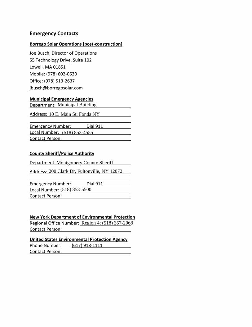
Emergency Contacts
Borrego Solar Operations [post-construction]
Joe Busch, Director of Operations
55 Technology Drive, Suite 102
Lowell, MA 01851
Mobile: (978) 602-0630
Office: (978) 513-2637
Municipal Emergency Agencies Department:
Address: Emergency Number: Dial 911 Local Number: Contact Person:
County Sheriff/Police Authority
Department:
Address: Emergency Number: Dial 911 Local Number: Contact Person:
New York Department of Environmental Protection Regional Office Number: Contact Person:
United States Environmental Protection Agency Phone Number: (617) 918-1111 Contact Person:
Municipal Building
10 E. Main St, Fonda NY
(518) 853-4555
Montgomery County Sheriff
200 Clark Dr, Fultonville, NY 12072
(518) 853-5500
Region 4; (518) 357-2068

Appendix F
Construction Site Notice
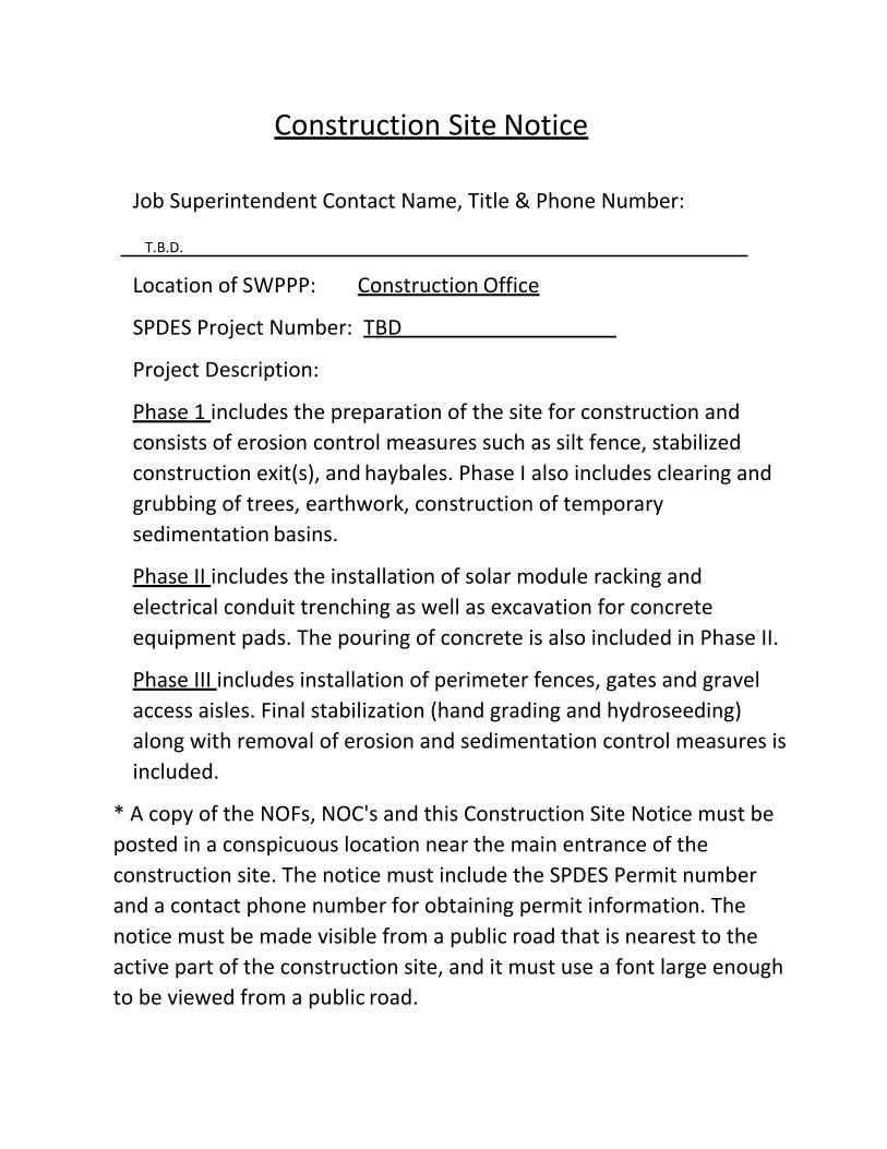
Construction Site Notice
Job Superintendent Contact Name, Title & Phone Number:
Location of SWPPP: Construction Office
SPDES Project Number: TBD
Project Description:
Phase 1 includes the preparation of the site for construction and
consists of erosion control measures such as silt fence, stabilized
construction exit(s), and haybales. Phase I also includes clearing and
grubbing of trees, earthwork, construction of temporary
sedimentation basins.
Phase II includes the installation of solar module racking and
electrical conduit trenching as well as excavation for concrete
equipment pads. The pouring of concrete is also included in Phase II.
Phase III includes installation of perimeter fences, gates and gravel
access aisles. Final stabilization (hand grading and hydroseeding)
along with removal of erosion and sedimentation control measures is
included.
* A copy of the NOFs, NOC's and this Construction Site Notice must be
posted in a conspicuous location near the main entrance of the
construction site. The notice must include the SPDES Permit number
and a contact phone number for obtaining permit information. The
notice must be made visible from a public road that is nearest to the
active part of the construction site, and it must use a font large enough
to be viewed from a public road.
T.B.D.

Appendix G
Subcontractor Certifications
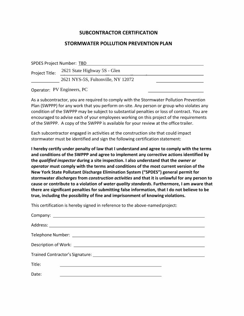
SUBCONTRACTOR CERTIFICATION
STORMWATER POLLUTION PREVENTION PLAN
SPDES Project Number: TBD
Project Title: 5,000.00kW Solar Energy Generating Facility
County Route 132,Perth New York 12010
Operator: Borrego Solar Systems, Inc.
As a subcontractor, you are required to comply with the Stormwater Pollution Prevention Plan (SWPPP) for any work that you perform on-site. Any person or group who violates any condition of the SWPPP may be subject to substantial penalties or loss of contract. You are encouraged to advise each of your employees working on this project of the requirements of the SWPPP. A copy of the SWPPP is available for your review at the office trailer.
Each subcontractor engaged in activities at the construction site that could impact stormwater must be identified and sign the following certification statement:
I hereby certify under penalty of law that I understand and agree to comply with the terms and conditions of the SWPPP and agree to implement any corrective actions identified by the qualified inspector during a site inspection. I also understand that the owner or operator must comply with the terms and conditions of the most current version of the New York State Pollutant Discharge Elimination System (“SPDES”) general permit for stormwater discharges from construction activities and that it is unlawful for any person to cause or contribute to a violation of water quality standards. Furthermore, I am aware that there are significant penalties for submitting false information, that I do not believe to be true, including the possibility of fine and imprisonment of knowing violations.
This certification is hereby signed in reference to the above-named project:
Company:
Address:
Telephone Number:
Description of Work:
Trained Contractor’s Signature:
Title:
Date:
2621 State Highway 5S - Glen
2621 NYS-5S, Fultonville, NY 12072
PV Engineers, PC

Appendix H
Blank Construction Site Log Book
Forms
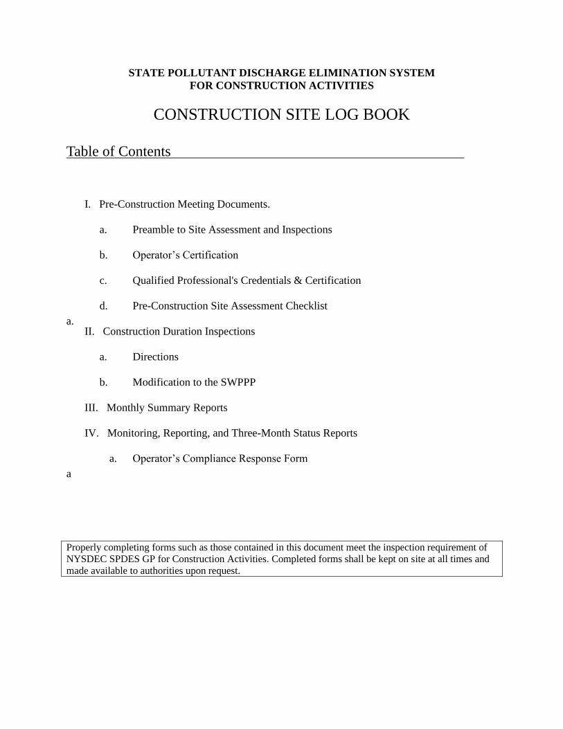
STATE POLLUTANT DISCHARGE ELIMINATION SYSTEM
FOR CONSTRUCTION ACTIVITIES
CONSTRUCTION SITE LOG BOOK
Table of Contents
I. Pre-Construction Meeting Documents.
a. Preamble to Site Assessment and Inspections
b. Operator’s Certification
c. Qualified Professional's Credentials & Certification
d. Pre-Construction Site Assessment Checklist
a. II. Construction Duration Inspections
a. Directions
b. Modification to the SWPPP
III. Monthly Summary Reports
IV. Monitoring, Reporting, and Three-Month Status Reports
a. Operator’s Compliance Response Form
a
Properly completing forms such as those contained in this document meet the inspection requirement of
NYSDEC SPDES GP for Construction Activities. Completed forms shall be kept on site at all times and
made available to authorities upon request.
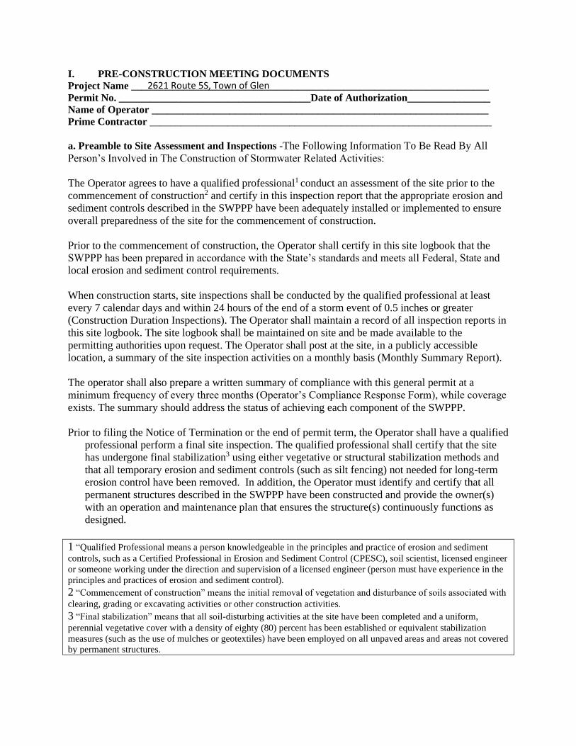
I. PRE-CONSTRUCTION MEETING DOCUMENTS
Project Name _____________________________________________________________________
Permit No. _____________________________________Date of Authorization________________
Name of Operator _________________________________________________________________
Prime Contractor __________________________________________________________________
a. Preamble to Site Assessment and Inspections -The Following Information To Be Read By All
Person’s Involved in The Construction of Stormwater Related Activities:
The Operator agrees to have a qualified professional1 conduct an assessment of the site prior to the
commencement of construction2 and certify in this inspection report that the appropriate erosion and
sediment controls described in the SWPPP have been adequately installed or implemented to ensure
overall preparedness of the site for the commencement of construction.
Prior to the commencement of construction, the Operator shall certify in this site logbook that the
SWPPP has been prepared in accordance with the State’s standards and meets all Federal, State and
local erosion and sediment control requirements.
When construction starts, site inspections shall be conducted by the qualified professional at least
every 7 calendar days and within 24 hours of the end of a storm event of 0.5 inches or greater
(Construction Duration Inspections). The Operator shall maintain a record of all inspection reports in
this site logbook. The site logbook shall be maintained on site and be made available to the
permitting authorities upon request. The Operator shall post at the site, in a publicly accessible
location, a summary of the site inspection activities on a monthly basis (Monthly Summary Report).
The operator shall also prepare a written summary of compliance with this general permit at a
minimum frequency of every three months (Operator’s Compliance Response Form), while coverage
exists. The summary should address the status of achieving each component of the SWPPP.
Prior to filing the Notice of Termination or the end of permit term, the Operator shall have a qualified
professional perform a final site inspection. The qualified professional shall certify that the site
has undergone final stabilization3 using either vegetative or structural stabilization methods and
that all temporary erosion and sediment controls (such as silt fencing) not needed for long-term
erosion control have been removed. In addition, the Operator must identify and certify that all
permanent structures described in the SWPPP have been constructed and provide the owner(s)
with an operation and maintenance plan that ensures the structure(s) continuously functions as
designed.
1 “Qualified Professional means a person knowledgeable in the principles and practice of erosion and sediment
controls, such as a Certified Professional in Erosion and Sediment Control (CPESC), soil scientist, licensed engineer
or someone working under the direction and supervision of a licensed engineer (person must have experience in the
principles and practices of erosion and sediment control). 2 “Commencement of construction” means the initial removal of vegetation and disturbance of soils associated with
clearing, grading or excavating activities or other construction activities. 3 “Final stabilization” means that all soil-disturbing activities at the site have been completed and a uniform,
perennial vegetative cover with a density of eighty (80) percent has been established or equivalent stabilization
measures (such as the use of mulches or geotextiles) have been employed on all unpaved areas and areas not covered
by permanent structures.
2621 Route 5S, Town of Glen
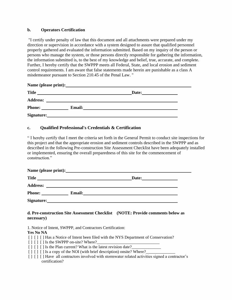
b. Operators Certification
"I certify under penalty of law that this document and all attachments were prepared under my
direction or supervision in accordance with a system designed to assure that qualified personnel
properly gathered and evaluated the information submitted. Based on my inquiry of the person or
persons who manage the system, or those persons directly responsible for gathering the information,
the information submitted is, to the best of my knowledge and belief, true, accurate, and complete.
Further, I hereby certify that the SWPPP meets all Federal, State, and local erosion and sediment
control requirements. I am aware that false statements made herein are punishable as a class A
misdemeanor pursuant to Section 210.45 of the Penal Law. "
Name (please print):
Title Date:
Address:
Phone: Email:
Signature:
c. Qualified Professional's Credentials & Certification
“ I hereby certify that I meet the criteria set forth in the General Permit to conduct site inspections for
this project and that the appropriate erosion and sediment controls described in the SWPPP and as
described in the following Pre-construction Site Assessment Checklist have been adequately installed
or implemented, ensuring the overall preparedness of this site for the commencement of
construction.”
Name (please print):
Title Date:
Address:
Phone: Email:
Signature:
d. Pre-construction Site Assessment Checklist (NOTE: Provide comments below as
necessary)
1. Notice of Intent, SWPPP, and Contractors Certification:
Yes No NA
[ ] [ ] [ ] Has a Notice of Intent been filed with the NYS Department of Conservation?
[ ] [ ] [ ] Is the SWPPP on-site? Where?______________________________
[ ] [ ] [ ] Is the Plan current? What is the latest revision date?______________
[ ] [ ] [ ] Is a copy of the NOI (with brief description) onsite? Where?______________
[ ] [ ] [ ] Have all contractors involved with stormwater related activities signed a contractor’s
certification?
Pre-construction Site Assessment Checklist (continued)
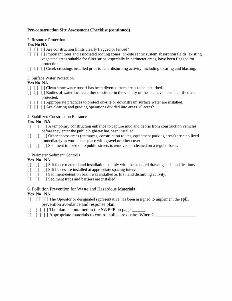
2. Resource Protection
Yes No NA
[ ] [ ] [ ] Are construction limits clearly flagged or fenced?
[ ] [ ] [ ] Important trees and associated rooting zones, on-site septic system absorption fields, existing
vegetated areas suitable for filter strips, especially in perimeter areas, have been flagged for
protection.
[ ] [ ] [ ] Creek crossings installed prior to land-disturbing activity, including clearing and blasting.
3. Surface Water Protection
Yes No NA
[ ] [ ] [ ] Clean stormwater runoff has been diverted from areas to be disturbed.
[ ] [ ] [ ] Bodies of water located either on site or in the vicinity of the site have been identified and
protected.
[ ] [ ] [ ] Appropriate practices to protect on-site or downstream surface water are installed.
[ ] [ ] [ ] Are clearing and grading operations divided into areas <5 acres?
4. Stabilized Construction Entrance
Yes No NA
[ ] [ ] [ ] A temporary construction entrance to capture mud and debris from construction vehicles
before they enter the public highway has been installed.
[ ] [ ] [ ] Other access areas (entrances, construction routes, equipment parking areas) are stabilized
immediately as work takes place with gravel or other cover.
[ ] [ ] [ ] Sediment tracked onto public streets is removed or cleaned on a regular basis.
5. Perimeter Sediment Controls
Yes No NA
[ ] [ ] [ ] Silt fence material and installation comply with the standard drawing and specifications.
[ ] [ ] [ ] Silt fences are installed at appropriate spacing intervals
[ ] [ ] [ ] Sediment/detention basin was installed as first land disturbing activity.
[ ] [ ] [ ] Sediment traps and barriers are installed.
6. Pollution Prevention for Waste and Hazardous Materials Yes No NA
[ ] [ ] [ ] The Operator or designated representative has been assigned to implement the spill
prevention avoidance and response plan.
[ ] [ ] [ ] The plan is contained in the SWPPP on page ______
[ ] [ ] [ ] Appropriate materials to control spills are onsite. Where? __________________
II. CONSTRUCTION DURATION INSPECTIONS
a. Directions:
Inspection Forms will be filled out during the entire construction phase of the project.
Required Elements:
(1) On a site map, indicate the extent of all disturbed site areas and drainage pathways. Indicate
site areas that are expected to undergo initial disturbance or significant site work within the next
14-day period;
(2) Indicate on a site map all areas of the site that have undergone temporary or permanent
stabilization;
(3) Indicate all disturbed site areas that have not undergone active site work during the previous
14-day period;
Inspect all sediment control practices and record the approximate degree of sediment
accumulation as a percentage of sediment storage volume (for example, 10 percent, 20
percent, 50 percent);
(5) Inspect all erosion and sediment control practices and record all maintenance requirements
such as verifying the integrity of barrier or diversion systems (earthen berms or silt fencing) and
containment systems (sediment basins and sediment traps). Identify any evidence of rill or gully
erosion occurring on slopes and any loss of stabilizing vegetation or seeding/mulching.
Document any excessive deposition of sediment or ponding water along barrier or diversion
systems. Record the depth of sediment within containment structures, any erosion near outlet and
overflow structures, and verify the ability of rock filters around perforated riser pipes to pass
water; and
(6) Immediately report to the Operator any deficiencies that are identified with the
implementation of the SWPPP.
CONSTRUCTION DURATION INSPECTIONS Page 1 of ______
SITE PLAN/SKETCH
_________________________________________ ____________________________________
Inspector (print name) Date of Inspection
________________________________________ ____________________________________
Qualified Professional (print name) Qualified Professional Signature
The above signed acknowledges that, to the best of his/her knowledge, all information provided
on the forms is accurate and complete.
CONSTRUCTION DURATION INSPECTIONS Page 2 of ______
Maintaining Water Quality
Yes No NA
[ ] [ ] [ ] Is there an increase in turbidity causing a substantial visible contrast to natural
conditions?
[ ] [ ] [ ] Is there residue from oil and floating substances, visible oil film, or globules or grease?
[ ] [ ] [ ] All disturbance is within the limits of the approved plans.
[ ] [ ] [ ] Have receiving lake/bay, stream, and/or wetland been impacted by silt from project?
Housekeeping
1. General Site Conditions
Yes No NA
[ ] [ ] [ ] Is construction site litter and debris appropriately managed?
[ ] [ ] [ ] Are facilities and equipment necessary for implementation of erosion and sediment
control in working order and/or properly maintained?
[ ] [ ] [ ] Is construction impacting the adjacent property?
[ ] [ ] [ ] Is dust adequately controlled?
2. Temporary Stream Crossing
Yes No NA
[ ] [ ] [ ] Maximum diameter pipes necessary to span creek without dredging are installed.
[ ] [ ] [ ] Installed non-woven geotextile fabric beneath approaches.
[ ] [ ] [ ] Is fill composed of aggregate (no earth or soil)?
[ ] [ ] [ ] Rock on approaches is clean enough to remove mud from vehicles & prevent sediment
from entering stream during high flow.
Runoff Control Practices
1. Excavation Dewatering
Yes No NA
[ ] [ ] [ ] Upstream and downstream berms (sandbags, inflatable dams, etc.) are installed per plan.
[ ] [ ] [ ] Clean water from upstream pool is being pumped to the downstream pool.
[ ] [ ] [ ] Sediment laden water from work area is being discharged to a silt-trapping device.
[ ] [ ] [ ] Constructed upstream berm with one-foot minimum freeboard.
2. Level Spreader
Yes No NA
[ ] [ ] [ ] Installed per plan.
[ ] [ ] [ ] Constructed on undisturbed soil, not on fill, receiving only clear, non-sediment laden
flow.
[ ] [ ] [ ] Flow sheets out of level spreader without erosion on downstream edge.
3. Interceptor Dikes and Swales
Yes No NA
[ ] [ ] [ ] Installed per plan with minimum side slopes 2H:1V or flatter.
[ ] [ ] [ ] Stabilized by geotextile fabric, seed, or mulch with no erosion occurring.
[ ] [ ] [ ] Sediment-laden runoff directed to sediment trapping structure
CONSTRUCTION DURATION INSPECTIONS Page 3 of ______
Runoff Control Practices (continued)
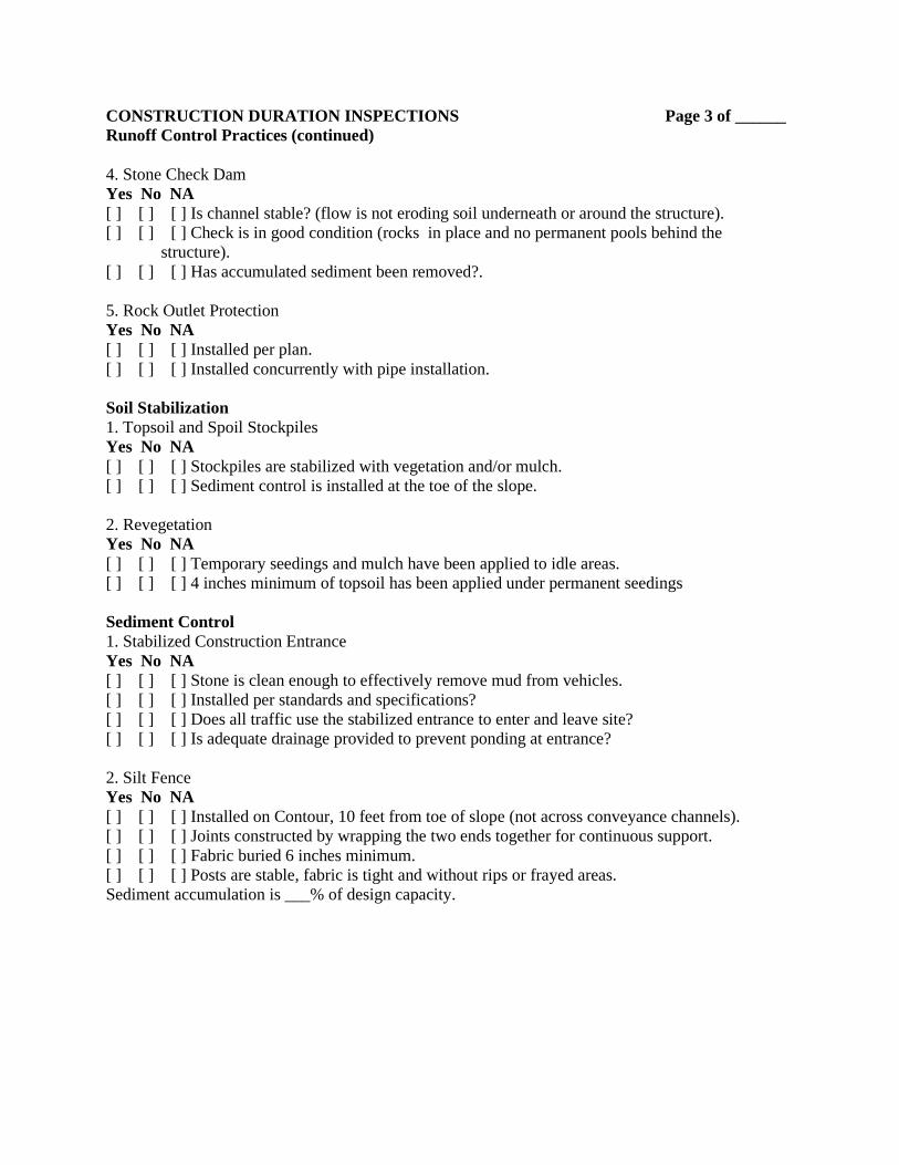
4. Stone Check Dam
Yes No NA
[ ] [ ] [ ] Is channel stable? (flow is not eroding soil underneath or around the structure).
[ ] [ ] [ ] Check is in good condition (rocks in place and no permanent pools behind the
structure).
[ ] [ ] [ ] Has accumulated sediment been removed?.
5. Rock Outlet Protection
Yes No NA
[ ] [ ] [ ] Installed per plan.
[ ] [ ] [ ] Installed concurrently with pipe installation.
Soil Stabilization
1. Topsoil and Spoil Stockpiles
Yes No NA
[ ] [ ] [ ] Stockpiles are stabilized with vegetation and/or mulch.
[ ] [ ] [ ] Sediment control is installed at the toe of the slope.
2. Revegetation
Yes No NA
[ ] [ ] [ ] Temporary seedings and mulch have been applied to idle areas.
[ ] [ ] [ ] 4 inches minimum of topsoil has been applied under permanent seedings
Sediment Control
1. Stabilized Construction Entrance
Yes No NA
[ ] [ ] [ ] Stone is clean enough to effectively remove mud from vehicles.
[ ] [ ] [ ] Installed per standards and specifications?
[ ] [ ] [ ] Does all traffic use the stabilized entrance to enter and leave site?
[ ] [ ] [ ] Is adequate drainage provided to prevent ponding at entrance?
2. Silt Fence
Yes No NA
[ ] [ ] [ ] Installed on Contour, 10 feet from toe of slope (not across conveyance channels).
[ ] [ ] [ ] Joints constructed by wrapping the two ends together for continuous support.
[ ] [ ] [ ] Fabric buried 6 inches minimum.
[ ] [ ] [ ] Posts are stable, fabric is tight and without rips or frayed areas.
Sediment accumulation is ___% of design capacity.
CONSTRUCTION DURATION INSPECTIONS Page 4 of ______
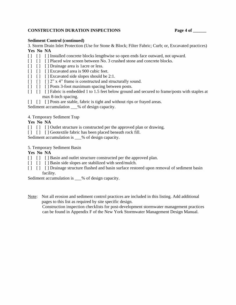
Sediment Control (continued)
3. Storm Drain Inlet Protection (Use for Stone & Block; Filter Fabric; Curb; or, Excavated practices)
Yes No NA
[ ] [ ] [ ] Installed concrete blocks lengthwise so open ends face outward, not upward.
[ ] [ ] [ ] Placed wire screen between No. 3 crushed stone and concrete blocks.
[ ] [ ] [ ] Drainage area is 1acre or less.
[ ] [ ] [ ] Excavated area is 900 cubic feet.
[ ] [ ] [ ] Excavated side slopes should be 2:1.
[ ] [ ] [ ] 2” x 4” frame is constructed and structurally sound.
[ ] [ ] [ ] Posts 3-foot maximum spacing between posts.
[ ] [ ] [ ] Fabric is embedded 1 to 1.5 feet below ground and secured to frame/posts with staples at
max 8-inch spacing.
[ ] [ ] [ ] Posts are stable, fabric is tight and without rips or frayed areas.
Sediment accumulation ___% of design capacity.
4. Temporary Sediment Trap
Yes No NA
[ ] [ ] [ ] Outlet structure is constructed per the approved plan or drawing.
[ ] [ ] [ ] Geotextile fabric has been placed beneath rock fill.
Sediment accumulation is ___% of design capacity.
5. Temporary Sediment Basin
Yes No NA
[ ] [ ] [ ] Basin and outlet structure constructed per the approved plan.
[ ] [ ] [ ] Basin side slopes are stabilized with seed/mulch.
[ ] [ ] [ ] Drainage structure flushed and basin surface restored upon removal of sediment basin
facility.
Sediment accumulation is ___% of design capacity.
Note: Not all erosion and sediment control practices are included in this listing. Add additional
pages to this list as required by site specific design.
Construction inspection checklists for post-development stormwater management practices
can be found in Appendix F of the New York Stormwater Management Design Manual.
CONSTRUCTION DURATION INSPECTIONS b. Modifications to the SWPPP (To be completed as described below)
The Operator shall amend the SWPPP whenever:
1. There is a significant change in design, construction, operation, or maintenance which may have a
significant effect on the potential for the discharge of pollutants to the waters of the United States and
which has not otherwise been addressed in the SWPPP; or
2. The SWPPP proves to be ineffective in:
a. Eliminating or significantly minimizing pollutants from sources identified in the SWPPP and as
required by this permit; or
b. Achieving the general objectives of controlling pollutants in stormwater discharges from permitted
construction activity; and
3. Additionally, the SWPPP shall be amended to identify any new contractor or subcontractor that will
implement any measure of the SWPPP.
Modification & Reason:
_________________________________________________________________________________
_________________________________________________________________________________
_________________________________________________________________________________
_________________________________________________________________________________
_________________________________________________________________________________
_________________________________________________________________________________
_________________________________________________________________________________
_________________________________________________________________________________
_________________________________________________________________________________
_________________________________________________________________________________
_________________________________________________________________________________
_________________________________________________________________________________
_________________________________________________________________________________
_________________________________________________________________________________
_________________________________________________________________________________
_________________________________________________________________________________
_________________________________________________________________________________
_________________________________________________________________________________
_________________________________________________________________________________
_________________________________________________________________________________
_________________________________________________________________________________
_________________________________________________________________________________
_________________________________________________________________________________
_________________________________________________________________________________
_________________________________________________________________________________
_________________________________________________________________________________
_________________________________________________________________________________
_________________________________________________________________________________
_________________________________________________________________________________
_________________________________________________________________________________
_________________________________________________________________________________
_________________________________________________________________________________
_________________________________________________________________________________
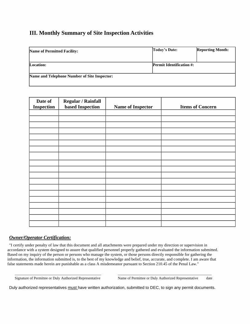
III. Monthly Summary of Site Inspection Activities
Name of Permitted Facility: Today’s Date: Reporting Month:
Location: Permit Identification #:
Name and Telephone Number of Site Inspector:
Date of
Inspection
Regular / Rainfall
based Inspection Name of Inspector Items of Concern
Owner/Operator Certification:
"I certify under penalty of law that this document and all attachments were prepared under my direction or supervision in
accordance with a system designed to assure that qualified personnel properly gathered and evaluated the information submitted.
Based on my inquiry of the person or persons who manage the system, or those persons directly responsible for gathering the
information, the information submitted is, to the best of my knowledge and belief, true, accurate, and complete. I am aware that
false statements made herein are punishable as a class A misdemeanor pursuant to Section 210.45 of the Penal Law."
_______________________________________________ ___________________________________________________
Signature of Permittee or Duly Authorized Representative Name of Permittee or Duly Authorized Representative date
Duly authorized representatives must have written authorization, submitted to DEC, to sign any permit documents.

Appendix I
Misc. Forms
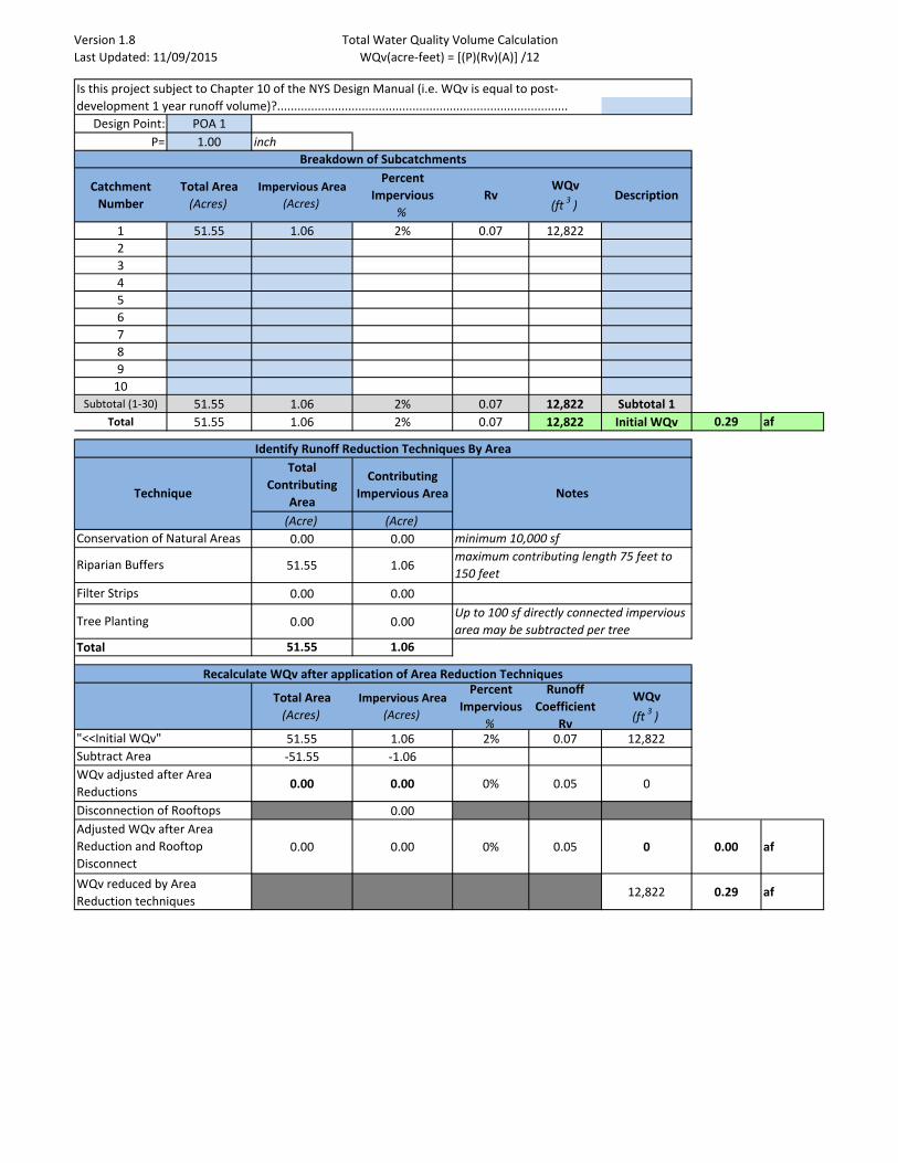
Version 1.8
Last Updated: 11/09/2015
Total Water Quality Volume Calculation
WQv(acre-feet) = [(P)(Rv)(A)] /12
Design Point: POA 1
P= 1.00 inch
Catchment
Number
Total Area
(Acres)
Impervious Area
(Acres)
Percent
Impervious
%
RvWQv
(ft3
)Description
1 51.55 1.06 2% 0.07 12,822
2
3
4
5
6
7
8
9
10
Subtotal (1-30) 51.55 1.06 2% 0.07 12,822 Subtotal 1
Total 51.55 1.06 2% 0.07 12,822 Initial WQv 0.29 af
Total
Contributing
Area
Contributing
Impervious Area
(Acre) (Acre)
0.00 0.00
51.55 1.06
0.00 0.00
0.00 0.00
51.55 1.06
Total Area
(Acres)
Impervious Area
(Acres)
Percent
Impervious
%
Runoff
Coefficient
Rv
WQv
(ft3
)
51.55 1.06 2% 0.07 12,822
-51.55 -1.06
0.00 0.00 0% 0.05 0
0.00
0.00 0.00 0% 0.05 0 0.00 af
12,822 0.29 af
Identify Runoff Reduction Techniques By Area
Breakdown of Subcatchments
Is this project subject to Chapter 10 of the NYS Design Manual (i.e. WQv is equal to post-
development 1 year runoff volume)?......................................................................................
"<<Initial WQv"
Recalculate WQv after application of Area Reduction Techniques
Riparian Buffersmaximum contributing length 75 feet to
150 feet
Up to 100 sf directly connected impervious
area may be subtracted per treeTree Planting
Filter Strips
Total
NotesTechnique
minimum 10,000 sfConservation of Natural Areas
WQv reduced by Area
Reduction techniques
Adjusted WQv after Area
Reduction and Rooftop
Disconnect
Subtract Area
Disconnection of Rooftops
WQv adjusted after Area
Reductions
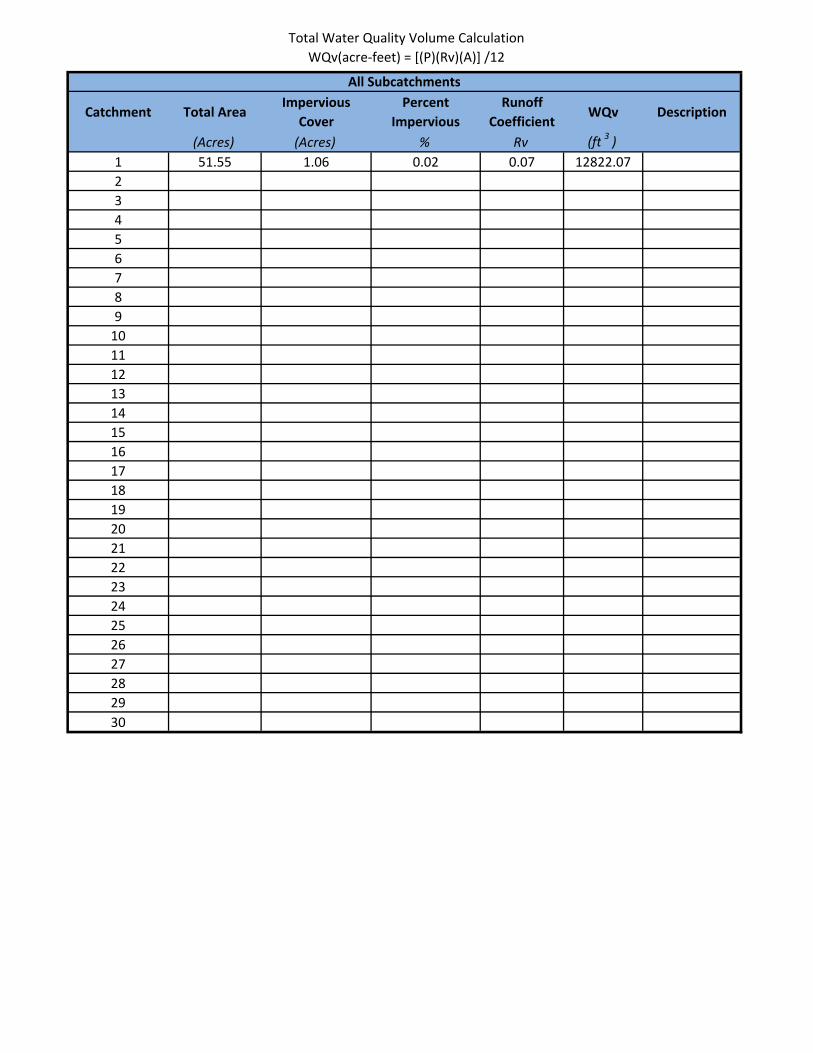
Total Water Quality Volume Calculation
WQv(acre-feet) = [(P)(Rv)(A)] /12
Catchment Total AreaImpervious
Cover
Percent
Impervious
Runoff
CoefficientWQv Description
(Acres) (Acres) % Rv (ft3
)
1 51.55 1.06 0.02 0.07 12822.07
2
3
4
5
6
7
8
9
10
11
12
13
14
15
16
17
18
19
20
21
22
23
24
25
26
27
28
29
30
All Subcatchments
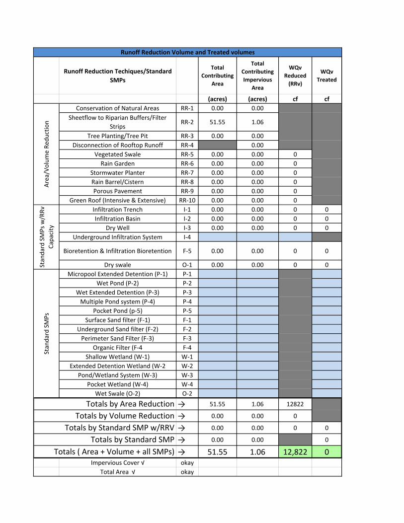
Runoff Reduction Techiques/Standard
SMPs
Total
Contributing
Area
Total
Contributing
Impervious
Area
WQv
Reduced
(RRv)
WQv
Treated
(acres) (acres) cf cf
Conservation of Natural Areas RR-1 0.00 0.00
Sheetflow to Riparian Buffers/Filter
StripsRR-2 51.55 1.06
Tree Planting/Tree Pit RR-3 0.00 0.00
Disconnection of Rooftop Runoff RR-4 0.00
Vegetated Swale RR-5 0.00 0.00 0
Rain Garden RR-6 0.00 0.00 0
Stormwater Planter RR-7 0.00 0.00 0
Rain Barrel/Cistern RR-8 0.00 0.00 0
Porous Pavement RR-9 0.00 0.00 0
Green Roof (Intensive & Extensive) RR-10 0.00 0.00 0
Infiltration Trench I-1 0.00 0.00 0 0
Infiltration Basin I-2 0.00 0.00 0 0
Dry Well I-3 0.00 0.00 0 0
Underground Infiltration System I-4
Bioretention & Infiltration Bioretention F-5 0.00 0.00 0 0
Dry swale O-1 0.00 0.00 0 0
Micropool Extended Detention (P-1) P-1
Wet Pond (P-2) P-2
Wet Extended Detention (P-3) P-3
Multiple Pond system (P-4) P-4
Pocket Pond (p-5) P-5
Surface Sand filter (F-1) F-1
Underground Sand filter (F-2) F-2
Perimeter Sand Filter (F-3) F-3
Organic Filter (F-4 F-4
Shallow Wetland (W-1) W-1
Extended Detention Wetland (W-2 W-2
Pond/Wetland System (W-3) W-3
Pocket Wetland (W-4) W-4
Wet Swale (O-2) O-2
→ 51.55 1.06 12822
→ 0.00 0.00 0
→ 0.00 0.00 0 0
→ 0.00 0.00 0
→ 51.55 1.06 12,822 0
Impervious Cover √ okay
Total Area √ okay
Totals by Volume Reduction
Totals by Standard SMP w/RRV
Totals by Standard SMP
Totals ( Area + Volume + all SMPs)
Runoff Reduction Volume and Treated volumes
Sta
nd
ard
SM
Ps
w/R
Rv
Ca
pa
city
Sta
nd
ard
SM
Ps
A
rea
/Vo
lum
e R
ed
uct
ion
Totals by Area Reduction
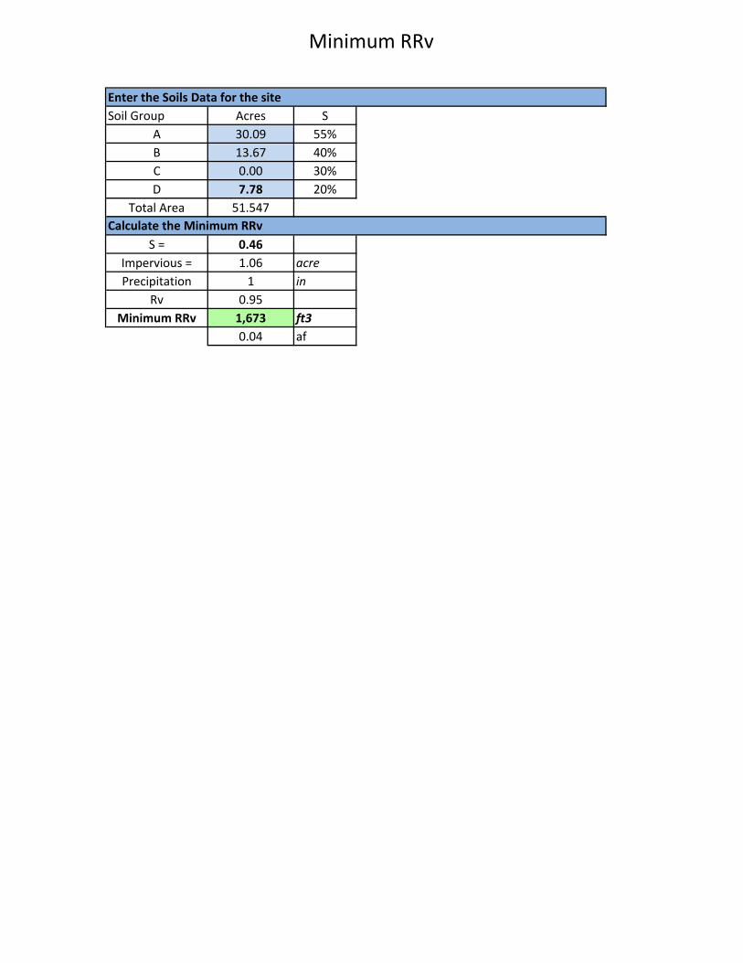
Minimum RRv
Soil Group Acres S
A 30.09 55%
B 13.67 40%
C 0.00 30%
D 7.78 20%
Total Area 51.547
S = 0.46
Impervious = 1.06 acre
Precipitation 1 in
Rv 0.95
Minimum RRv 1,673 ft3
0.04 af
Enter the Soils Data for the site
Calculate the Minimum RRv
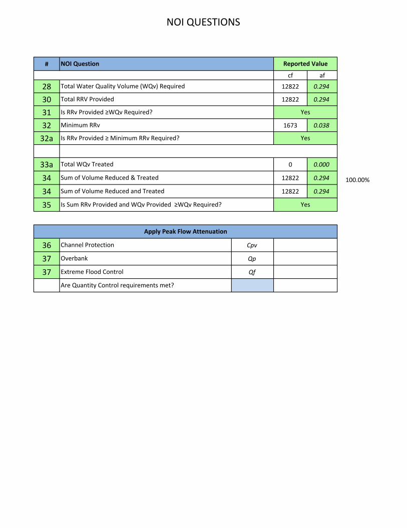
NOI QUESTIONS
#
cf af
28 12822 0.294
30 12822 0.294
31
32 1673 0.038
32a
33a 0 0.000
34 12822 0.294 100.00%
34 12822 0.294
35
36 Cpv
37 Qp
37 Qf
Reported Value
Yes
Yes
Yes
Minimum RRv
NOI Question
Sum of Volume Reduced & Treated
Total WQv Treated
Total RRV Provided
Total Water Quality Volume (WQv) Required
Is Sum RRv Provided and WQv Provided ≥WQv Required?
Sum of Volume Reduced and Treated
Is RRv Provided ≥ Minimum RRv Required?
Is RRv Provided ≥WQv Required?
Are Quantity Control requirements met?
Channel Protection
Apply Peak Flow Attenuation
Overbank
Extreme Flood Control
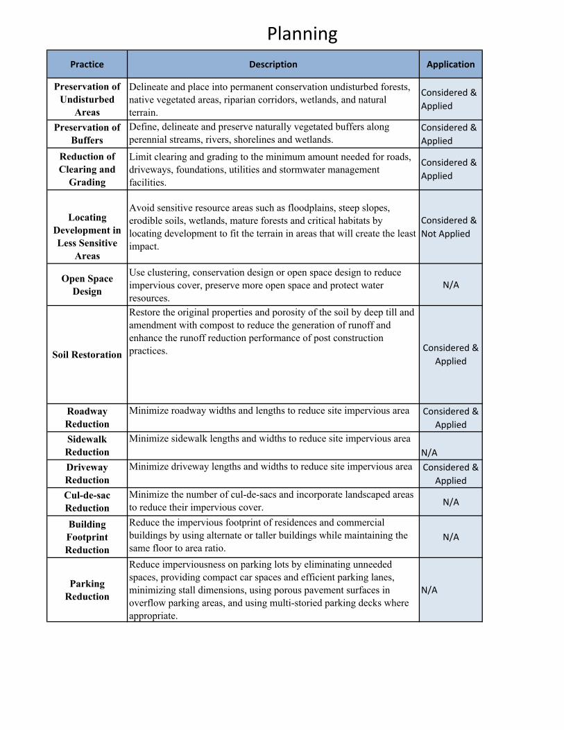
Planning
Practice Description Application
Preservation of
Undisturbed
Areas
Delineate and place into permanent conservation undisturbed forests,
native vegetated areas, riparian corridors, wetlands, and natural
terrain.
Considered &
Applied
Preservation of
Buffers
Define, delineate and preserve naturally vegetated buffers along
perennial streams, rivers, shorelines and wetlands.
Considered &
Applied
Reduction of
Clearing and
Grading
Limit clearing and grading to the minimum amount needed for roads,
driveways, foundations, utilities and stormwater management
facilities.
Considered &
Applied
Locating
Development in
Less Sensitive
Areas
Avoid sensitive resource areas such as floodplains, steep slopes,
erodible soils, wetlands, mature forests and critical habitats by
locating development to fit the terrain in areas that will create the least
impact.
Considered &
Not Applied
Open Space
Design
Use clustering, conservation design or open space design to reduce
impervious cover, preserve more open space and protect water
resources.
N/A
Restore the original properties and porosity of the soil by deep till and
amendment with compost to reduce the generation of runoff and
enhance the runoff reduction performance of post construction
practices.
Roadway
Reduction
Minimize roadway widths and lengths to reduce site impervious area Considered &
Applied
Sidewalk
Reduction
Minimize sidewalk lengths and widths to reduce site impervious area
N/A
Driveway
Reduction
Minimize driveway lengths and widths to reduce site impervious area Considered &
Applied
Cul-de-sac
Reduction
Minimize the number of cul-de-sacs and incorporate landscaped areas
to reduce their impervious cover.N/A
Building
Footprint
Reduction
Reduce the impervious footprint of residences and commercial
buildings by using alternate or taller buildings while maintaining the
same floor to area ratio.N/A
Parking
Reduction
Reduce imperviousness on parking lots by eliminating unneeded
spaces, providing compact car spaces and efficient parking lanes,
minimizing stall dimensions, using porous pavement surfaces in
overflow parking areas, and using multi-storied parking decks where
appropriate.
N/A
Soil RestorationConsidered &
Applied
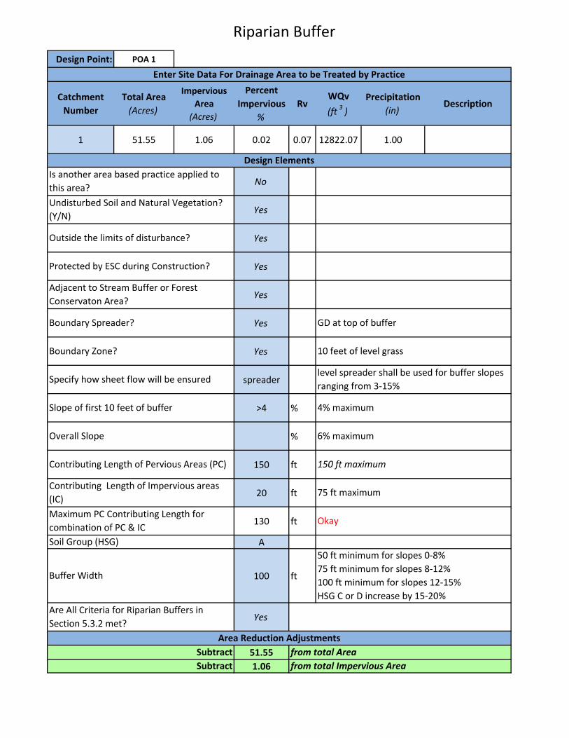
Riparian Buffer
Design Point: POA 1
Catchment
Number
Total Area
(Acres)
Impervious
Area
(Acres)
Percent
Impervious
%
RvWQv
(ft3
)
Precipitation
(in)Description
1 51.55 1.06 0.02 0.07 12822.07 1.00
No
Yes
Yes
Yes
Yes
Yes
Yes
spreader
>4 %
%
150 ft
20 ft
130 ft
A
100 ft
Yes
51.55
1.06
Enter Site Data For Drainage Area to be Treated by Practice
Design Elements
Is another area based practice applied to
this area?
Outside the limits of disturbance?
Protected by ESC during Construction?
Adjacent to Stream Buffer or Forest
Conservaton Area?
Boundary Spreader?
Boundary Zone?
Specify how sheet flow will be ensured
Slope of first 10 feet of buffer
Overall Slope
Contributing Length of Pervious Areas (PC) 150 ft maximum
6% maximum
4% maximum
10 feet of level grass
GD at top of buffer
Maximum PC Contributing Length for
combination of PC & ICOkay
Undisturbed Soil and Natural Vegetation?
(Y/N)
Subtract
from total Area
from total Impervious Area
Are All Criteria for Riparian Buffers in
Section 5.3.2 met?
Subtract
Contributing Length of Impervious areas
(IC)75 ft maximum
Buffer Width
50 ft minimum for slopes 0-8%
75 ft minimum for slopes 8-12%
100 ft minimum for slopes 12-15%
HSG C or D increase by 15-20%
level spreader shall be used for buffer slopes
ranging from 3-15%
Soil Group (HSG)
Area Reduction Adjustments

Appendix J
Endangered Species
Documentation
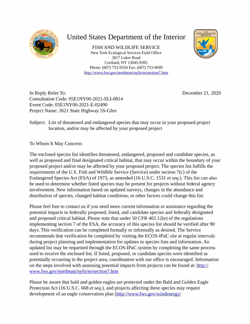
December 21, 2020
United States Department of the InteriorFISH AND WILDLIFE SERVICE
New York Ecological Services Field Office3817 Luker Road
Cortland, NY 13045-9385Phone: (607) 753-9334 Fax: (607) 753-9699
http://www.fws.gov/northeast/nyfo/es/section7.htm
In Reply Refer To: Consultation Code: 05E1NY00-2021-SLI-0814 Event Code: 05E1NY00-2021-E-02490 Project Name: 2621 State Highway 5S-Glen Subject: List of threatened and endangered species that may occur in your proposed project
location, and/or may be affected by your proposed project
To Whom It May Concern:
The enclosed species list identifies threatened, endangered, proposed and candidate species, as well as proposed and final designated critical habitat, that may occur within the boundary of your proposed project and/or may be affected by your proposed project. The species list fulfills the requirements of the U.S. Fish and Wildlife Service (Service) under section 7(c) of the Endangered Species Act (ESA) of 1973, as amended (16 U.S.C. 1531 et seq.). This list can also be used to determine whether listed species may be present for projects without federal agency involvement. New information based on updated surveys, changes in the abundance and distribution of species, changed habitat conditions, or other factors could change this list.
Please feel free to contact us if you need more current information or assistance regarding the potential impacts to federally proposed, listed, and candidate species and federally designated and proposed critical habitat. Please note that under 50 CFR 402.12(e) of the regulations implementing section 7 of the ESA, the accuracy of this species list should be verified after 90 days. This verification can be completed formally or informally as desired. The Service recommends that verification be completed by visiting the ECOS-IPaC site at regular intervals during project planning and implementation for updates to species lists and information. An updated list may be requested through the ECOS-IPaC system by completing the same process used to receive the enclosed list. If listed, proposed, or candidate species were identified as potentially occurring in the project area, coordination with our office is encouraged. Information on the steps involved with assessing potential impacts from projects can be found at: http:// www.fws.gov/northeast/nyfo/es/section7.htm
Please be aware that bald and golden eagles are protected under the Bald and Golden Eagle Protection Act (16 U.S.C. 668 et seq.), and projects affecting these species may require development of an eagle conservation plan (http://www.fws.gov/windenergy/

12/21/2020 Event Code: 05E1NY00-2021-E-02490 2
▪
eagle_guidance.html). Additionally, wind energy projects should follow the Services wind energy guidelines (http://www.fws.gov/windenergy/) for minimizing impacts to migratory birds and bats.
Guidance for minimizing impacts to migratory birds for projects including communications towers (e.g., cellular, digital television, radio, and emergency broadcast) can be found at: http:// www.fws.gov/migratorybirds/CurrentBirdIssues/Hazards/towers/towers.htm; http:// www.towerkill.com; and http://www.fws.gov/migratorybirds/CurrentBirdIssues/Hazards/towers/ comtow.html.
We appreciate your concern for threatened and endangered species. The Service encourages Federal agencies to include conservation of threatened and endangered species into their project planning to further the purposes of the ESA. Please include the Consultation Tracking Number in the header of this letter with any request for consultation or correspondence about your project that you submit to our office.
Attachment(s):
Official Species List

12/21/2020 Event Code: 05E1NY00-2021-E-02490 1
Official Species ListThis list is provided pursuant to Section 7 of the Endangered Species Act, and fulfills the requirement for Federal agencies to "request of the Secretary of the Interior information whether any species which is listed or proposed to be listed may be present in the area of a proposed action".
This species list is provided by:
New York Ecological Services Field Office3817 Luker RoadCortland, NY 13045-9385(607) 753-9334
12/21/2020 Event Code: 05E1NY00-2021-E-02490 2
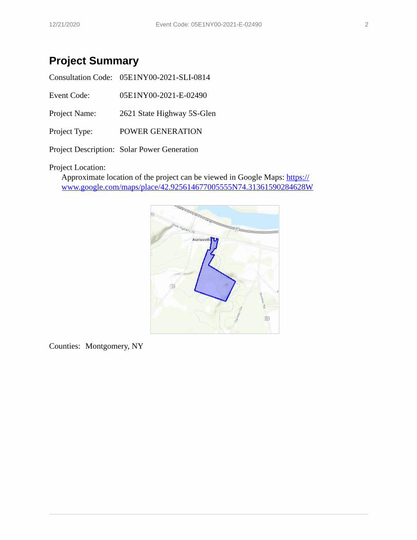
Project SummaryConsultation Code: 05E1NY00-2021-SLI-0814
Event Code: 05E1NY00-2021-E-02490
Project Name: 2621 State Highway 5S-Glen
Project Type: POWER GENERATION
Project Description: Solar Power Generation
Project Location:Approximate location of the project can be viewed in Google Maps: https:// www.google.com/maps/place/42.925614677005555N74.31361590284628W
Counties: Montgomery, NY

12/21/2020 Event Code: 05E1NY00-2021-E-02490 3
1.
Endangered Species Act SpeciesThere is a total of 0 threatened, endangered, or candidate species on this species list.
Species on this list should be considered in an effects analysis for your project and could include species that exist in another geographic area. For example, certain fish may appear on the species list because a project could affect downstream species.
IPaC does not display listed species or critical habitats under the sole jurisdiction of NOAA Fisheries , as USFWS does not have the authority to speak on behalf of NOAA and the Department of Commerce.
See the "Critical habitats" section below for those critical habitats that lie wholly or partially within your project area under this office's jurisdiction. Please contact the designated FWS office if you have questions.
NOAA Fisheries, also known as the National Marine Fisheries Service (NMFS), is an office of the National Oceanic and Atmospheric Administration within the Department of Commerce.
Critical habitatsTHERE ARE NO CRITICAL HABITATS WITHIN YOUR PROJECT AREA UNDER THIS OFFICE'S JURISDICTION.
1

Appendix K
HydroCAD Output
Table of ContentsHydroCAD Post-Development_D_Single DA NoStorage_040121 Printed 4/8/2021Prepared by ARICO
HydroCAD® 10.10-5a s/n 10839 © 2020 HydroCAD Software Solutions LLC
TABLE OF CONTENTS
Project Reports
1 Routing Diagram
2 Rainfall Events Listing (selected events)
3 Area Listing (all nodes)
4 Ground Covers (all nodes)
1-Year Event
5 Subcat 1: Subcat 1
10-Year Event
6 Subcat 1: Subcat 1
100-Year Event
7 Subcat 1: Subcat 1
1A
Subcat 1
Routing Diagram for HydroCAD Pre-Development_D_Single DA_040121
Prepared by ARICO, Printed 4/8/2021HydroCAD® 10.10-5a s/n 10839 © 2020 HydroCAD Software Solutions LLC
Subcat Reach Pond Link
HydroCAD Pre-Development_D_Single DA_040121 Printed 4/8/2021Prepared by ARICO
Page 2HydroCAD® 10.10-5a s/n 10839 © 2020 HydroCAD Software Solutions LLC
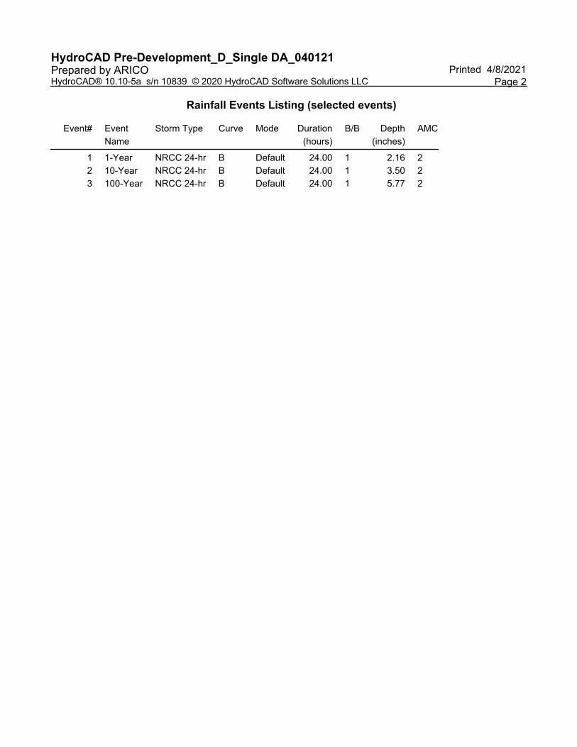
Rainfall Events Listing (selected events)
Event# Event
Name
Storm Type Curve Mode Duration
(hours)
B/B Depth
(inches)
AMC
1 1-Year NRCC 24-hr B Default 24.00 1 2.16 2
2 10-Year NRCC 24-hr B Default 24.00 1 3.50 2
3 100-Year NRCC 24-hr B Default 24.00 1 5.77 2
HydroCAD Pre-Development_D_Single DA_040121 Printed 4/8/2021Prepared by ARICO
Page 3HydroCAD® 10.10-5a s/n 10839 © 2020 HydroCAD Software Solutions LLC
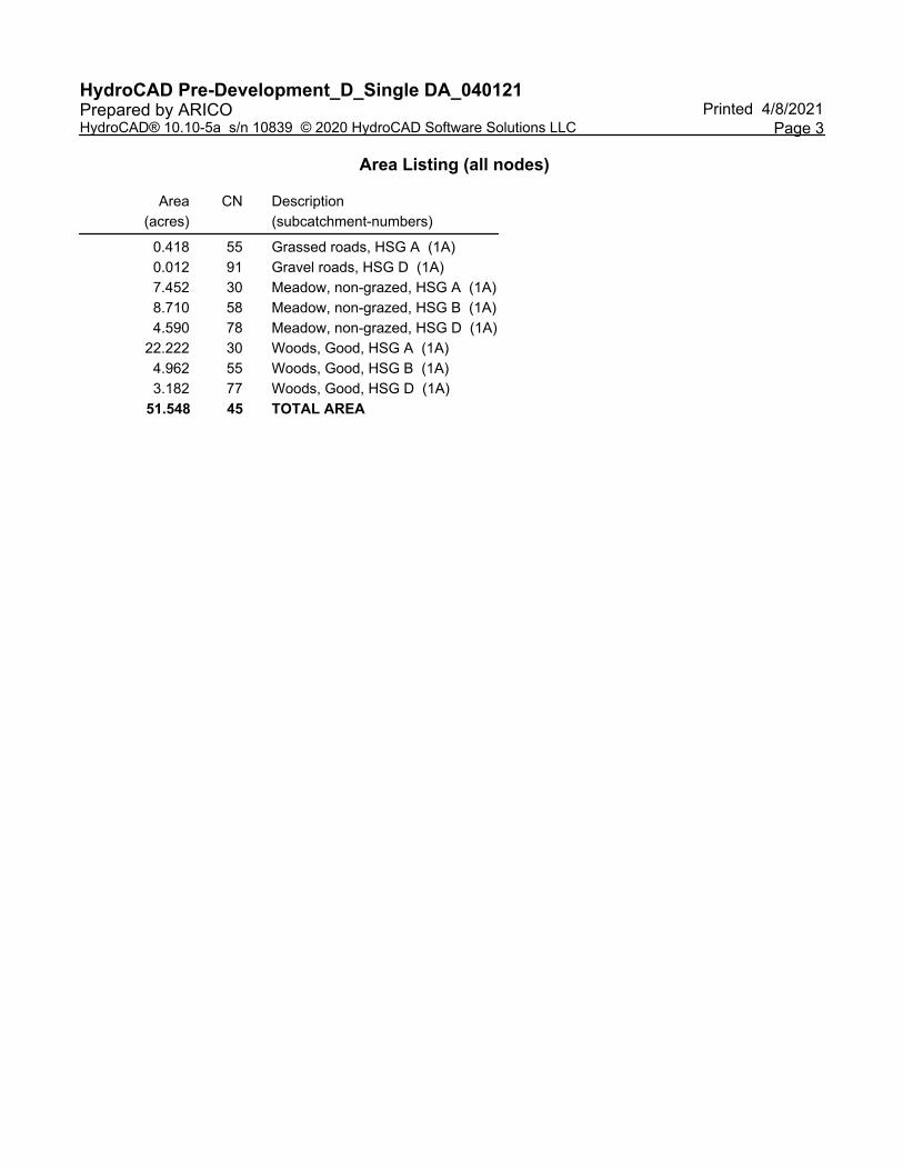
Area Listing (all nodes)
Area
(acres)
CN Description
(subcatchment-numbers)
0.418 55 Grassed roads, HSG A (1A)
0.012 91 Gravel roads, HSG D (1A)
7.452 30 Meadow, non-grazed, HSG A (1A)
8.710 58 Meadow, non-grazed, HSG B (1A)
4.590 78 Meadow, non-grazed, HSG D (1A)
22.222 30 Woods, Good, HSG A (1A)
4.962 55 Woods, Good, HSG B (1A)
3.182 77 Woods, Good, HSG D (1A)
51.548 45 TOTAL AREA
HydroCAD Pre-Development_D_Single DA_040121 Printed 4/8/2021Prepared by ARICO
Page 4HydroCAD® 10.10-5a s/n 10839 © 2020 HydroCAD Software Solutions LLC
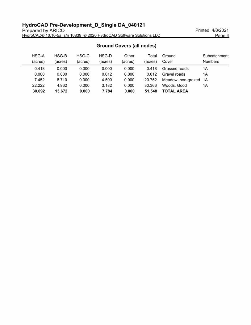
Ground Covers (all nodes)
HSG-A
(acres)
HSG-B
(acres)
HSG-C
(acres)
HSG-D
(acres)
Other
(acres)
Total
(acres)
Ground
Cover
Subcatchment
Numbers
0.418 0.000 0.000 0.000 0.000 0.418 Grassed roads 1A
0.000 0.000 0.000 0.012 0.000 0.012 Gravel roads 1A
7.452 8.710 0.000 4.590 0.000 20.752 Meadow, non-grazed 1A
22.222 4.962 0.000 3.182 0.000 30.366 Woods, Good 1A
30.092 13.672 0.000 7.784 0.000 51.548 TOTAL AREA
NRCC 24-hr B 1-Year Rainfall=2.16"HydroCAD Pre-Development_D_Single DA_040121 Printed 4/8/2021Prepared by ARICO
Page 5HydroCAD® 10.10-5a s/n 10839 © 2020 HydroCAD Software Solutions LLC
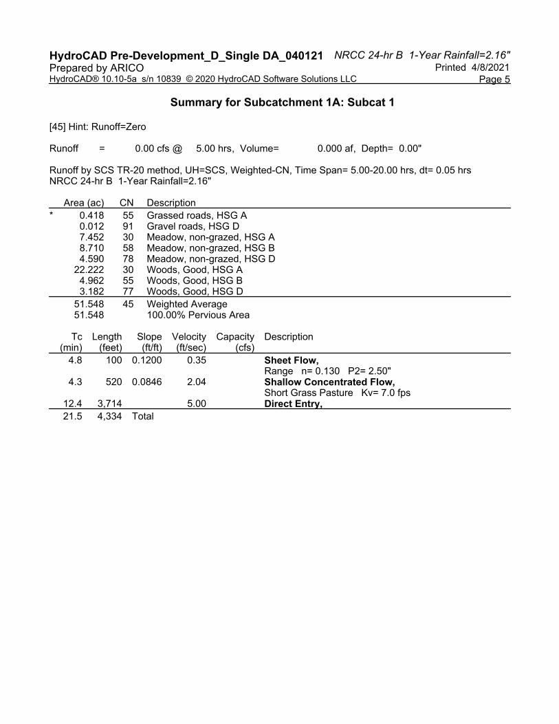
Summary for Subcatchment 1A: Subcat 1
[45] Hint: Runoff=Zero
Runoff = 0.00 cfs @ 5.00 hrs, Volume= 0.000 af, Depth= 0.00"
Runoff by SCS TR-20 method, UH=SCS, Weighted-CN, Time Span= 5.00-20.00 hrs, dt= 0.05 hrsNRCC 24-hr B 1-Year Rainfall=2.16"
Area (ac) CN Description
* 0.418 55 Grassed roads, HSG A0.012 91 Gravel roads, HSG D7.452 30 Meadow, non-grazed, HSG A8.710 58 Meadow, non-grazed, HSG B4.590 78 Meadow, non-grazed, HSG D
22.222 30 Woods, Good, HSG A4.962 55 Woods, Good, HSG B3.182 77 Woods, Good, HSG D
51.548 45 Weighted Average51.548 100.00% Pervious Area
Tc Length Slope Velocity Capacity Description(min) (feet) (ft/ft) (ft/sec) (cfs)
4.8 100 0.1200 0.35 Sheet Flow, Range n= 0.130 P2= 2.50"
4.3 520 0.0846 2.04 Shallow Concentrated Flow, Short Grass Pasture Kv= 7.0 fps
12.4 3,714 5.00 Direct Entry,
21.5 4,334 Total

NRCC 24-hr B 10-Year Rainfall=3.50"HydroCAD Pre-Development_D_Single DA_040121 Printed 4/8/2021Prepared by ARICO
Page 6HydroCAD® 10.10-5a s/n 10839 © 2020 HydroCAD Software Solutions LLC
Summary for Subcatchment 1A: Subcat 1
Runoff = 0.59 cfs @ 13.49 hrs, Volume= 0.253 af, Depth> 0.06"
Runoff by SCS TR-20 method, UH=SCS, Weighted-CN, Time Span= 5.00-20.00 hrs, dt= 0.05 hrsNRCC 24-hr B 10-Year Rainfall=3.50"
Area (ac) CN Description
* 0.418 55 Grassed roads, HSG A0.012 91 Gravel roads, HSG D7.452 30 Meadow, non-grazed, HSG A8.710 58 Meadow, non-grazed, HSG B4.590 78 Meadow, non-grazed, HSG D
22.222 30 Woods, Good, HSG A4.962 55 Woods, Good, HSG B3.182 77 Woods, Good, HSG D
51.548 45 Weighted Average51.548 100.00% Pervious Area
Tc Length Slope Velocity Capacity Description(min) (feet) (ft/ft) (ft/sec) (cfs)
4.8 100 0.1200 0.35 Sheet Flow, Range n= 0.130 P2= 2.50"
4.3 520 0.0846 2.04 Shallow Concentrated Flow, Short Grass Pasture Kv= 7.0 fps
12.4 3,714 5.00 Direct Entry,
21.5 4,334 Total
NRCC 24-hr B 100-Year Rainfall=5.77"HydroCAD Pre-Development_D_Single DA_040121 Printed 4/8/2021Prepared by ARICO
Page 7HydroCAD® 10.10-5a s/n 10839 © 2020 HydroCAD Software Solutions LLC
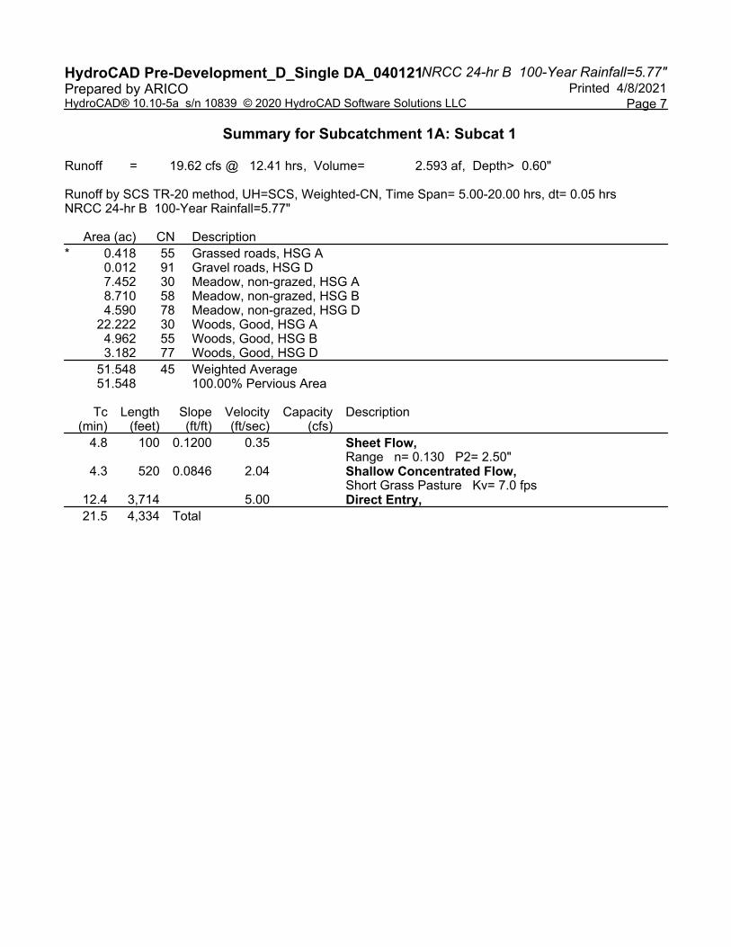
Summary for Subcatchment 1A: Subcat 1
Runoff = 19.62 cfs @ 12.41 hrs, Volume= 2.593 af, Depth> 0.60"
Runoff by SCS TR-20 method, UH=SCS, Weighted-CN, Time Span= 5.00-20.00 hrs, dt= 0.05 hrsNRCC 24-hr B 100-Year Rainfall=5.77"
Area (ac) CN Description
* 0.418 55 Grassed roads, HSG A0.012 91 Gravel roads, HSG D7.452 30 Meadow, non-grazed, HSG A8.710 58 Meadow, non-grazed, HSG B4.590 78 Meadow, non-grazed, HSG D
22.222 30 Woods, Good, HSG A4.962 55 Woods, Good, HSG B3.182 77 Woods, Good, HSG D
51.548 45 Weighted Average51.548 100.00% Pervious Area
Tc Length Slope Velocity Capacity Description(min) (feet) (ft/ft) (ft/sec) (cfs)
4.8 100 0.1200 0.35 Sheet Flow, Range n= 0.130 P2= 2.50"
4.3 520 0.0846 2.04 Shallow Concentrated Flow, Short Grass Pasture Kv= 7.0 fps
12.4 3,714 5.00 Direct Entry,
21.5 4,334 Total
Table of ContentsHydroCAD Pre-Development_D_Single DA_040121 Printed 4/8/2021Prepared by ARICO
HydroCAD® 10.10-5a s/n 10839 © 2020 HydroCAD Software Solutions LLC
TABLE OF CONTENTS
Project Reports
1 Routing Diagram
2 Rainfall Events Listing (selected events)
3 Area Listing (all nodes)
4 Ground Covers (all nodes)
1-Year Event
5 Subcat 1A: Subcat 1
10-Year Event
6 Subcat 1A: Subcat 1
100-Year Event
7 Subcat 1A: Subcat 1
1
Subcat 1
Routing Diagram for HydroCAD Post-Development_D_Single DA NoStorage_040121
Prepared by ARICO, Printed 4/8/2021HydroCAD® 10.10-5a s/n 10839 © 2020 HydroCAD Software Solutions LLC
Subcat Reach Pond Link
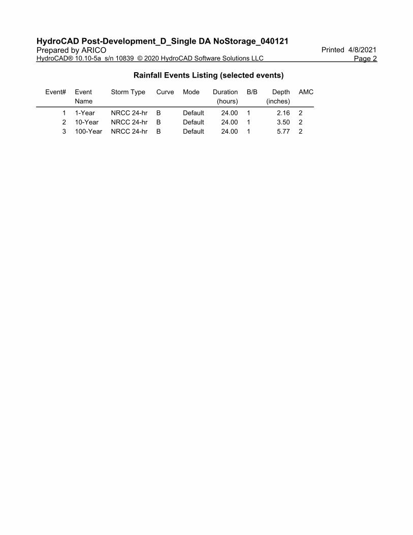
HydroCAD Post-Development_D_Single DA NoStorage_040121 Printed 4/8/2021Prepared by ARICO
Page 2HydroCAD® 10.10-5a s/n 10839 © 2020 HydroCAD Software Solutions LLC
Rainfall Events Listing (selected events)
Event# Event
Name
Storm Type Curve Mode Duration
(hours)
B/B Depth
(inches)
AMC
1 1-Year NRCC 24-hr B Default 24.00 1 2.16 2
2 10-Year NRCC 24-hr B Default 24.00 1 3.50 2
3 100-Year NRCC 24-hr B Default 24.00 1 5.77 2
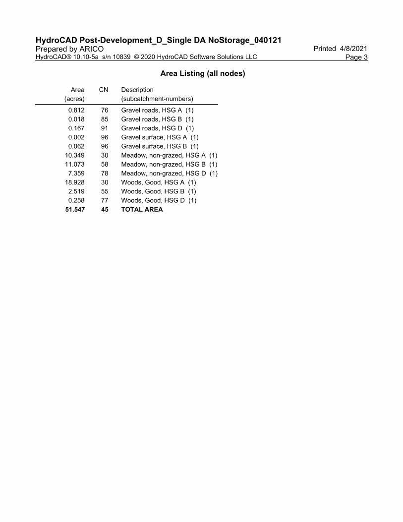
HydroCAD Post-Development_D_Single DA NoStorage_040121 Printed 4/8/2021Prepared by ARICO
Page 3HydroCAD® 10.10-5a s/n 10839 © 2020 HydroCAD Software Solutions LLC
Area Listing (all nodes)
Area
(acres)
CN Description
(subcatchment-numbers)
0.812 76 Gravel roads, HSG A (1)
0.018 85 Gravel roads, HSG B (1)
0.167 91 Gravel roads, HSG D (1)
0.002 96 Gravel surface, HSG A (1)
0.062 96 Gravel surface, HSG B (1)
10.349 30 Meadow, non-grazed, HSG A (1)
11.073 58 Meadow, non-grazed, HSG B (1)
7.359 78 Meadow, non-grazed, HSG D (1)
18.928 30 Woods, Good, HSG A (1)
2.519 55 Woods, Good, HSG B (1)
0.258 77 Woods, Good, HSG D (1)
51.547 45 TOTAL AREA
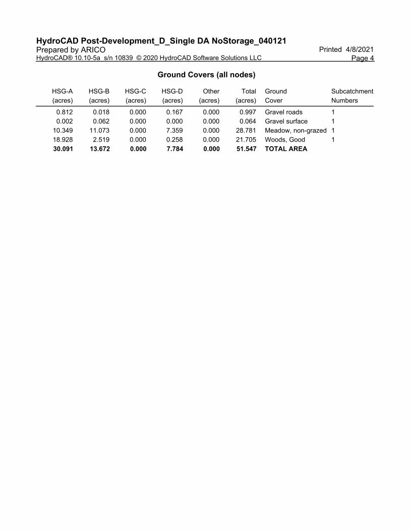
HydroCAD Post-Development_D_Single DA NoStorage_040121 Printed 4/8/2021Prepared by ARICO
Page 4HydroCAD® 10.10-5a s/n 10839 © 2020 HydroCAD Software Solutions LLC
Ground Covers (all nodes)
HSG-A
(acres)
HSG-B
(acres)
HSG-C
(acres)
HSG-D
(acres)
Other
(acres)
Total
(acres)
Ground
Cover
Subcatchment
Numbers
0.812 0.018 0.000 0.167 0.000 0.997 Gravel roads 1
0.002 0.062 0.000 0.000 0.000 0.064 Gravel surface 1
10.349 11.073 0.000 7.359 0.000 28.781 Meadow, non-grazed 1
18.928 2.519 0.000 0.258 0.000 21.705 Woods, Good 1
30.091 13.672 0.000 7.784 0.000 51.547 TOTAL AREA
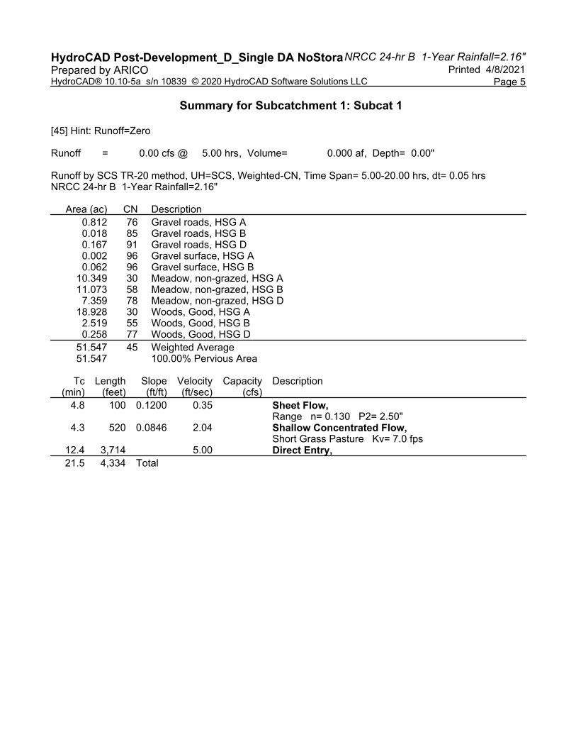
NRCC 24-hr B 1-Year Rainfall=2.16"HydroCAD Post-Development_D_Single DA NoStora Printed 4/8/2021Prepared by ARICO
Page 5HydroCAD® 10.10-5a s/n 10839 © 2020 HydroCAD Software Solutions LLC
Summary for Subcatchment 1: Subcat 1
[45] Hint: Runoff=Zero
Runoff = 0.00 cfs @ 5.00 hrs, Volume= 0.000 af, Depth= 0.00"
Runoff by SCS TR-20 method, UH=SCS, Weighted-CN, Time Span= 5.00-20.00 hrs, dt= 0.05 hrsNRCC 24-hr B 1-Year Rainfall=2.16"
Area (ac) CN Description
0.812 76 Gravel roads, HSG A0.018 85 Gravel roads, HSG B0.167 91 Gravel roads, HSG D0.002 96 Gravel surface, HSG A0.062 96 Gravel surface, HSG B
10.349 30 Meadow, non-grazed, HSG A11.073 58 Meadow, non-grazed, HSG B
7.359 78 Meadow, non-grazed, HSG D18.928 30 Woods, Good, HSG A
2.519 55 Woods, Good, HSG B0.258 77 Woods, Good, HSG D
51.547 45 Weighted Average51.547 100.00% Pervious Area
Tc Length Slope Velocity Capacity Description(min) (feet) (ft/ft) (ft/sec) (cfs)
4.8 100 0.1200 0.35 Sheet Flow, Range n= 0.130 P2= 2.50"
4.3 520 0.0846 2.04 Shallow Concentrated Flow, Short Grass Pasture Kv= 7.0 fps
12.4 3,714 5.00 Direct Entry,
21.5 4,334 Total
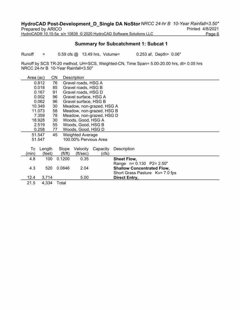
NRCC 24-hr B 10-Year Rainfall=3.50"HydroCAD Post-Development_D_Single DA NoStor Printed 4/8/2021Prepared by ARICO
Page 6HydroCAD® 10.10-5a s/n 10839 © 2020 HydroCAD Software Solutions LLC
Summary for Subcatchment 1: Subcat 1
Runoff = 0.59 cfs @ 13.49 hrs, Volume= 0.253 af, Depth> 0.06"
Runoff by SCS TR-20 method, UH=SCS, Weighted-CN, Time Span= 5.00-20.00 hrs, dt= 0.05 hrsNRCC 24-hr B 10-Year Rainfall=3.50"
Area (ac) CN Description
0.812 76 Gravel roads, HSG A0.018 85 Gravel roads, HSG B0.167 91 Gravel roads, HSG D0.002 96 Gravel surface, HSG A0.062 96 Gravel surface, HSG B
10.349 30 Meadow, non-grazed, HSG A11.073 58 Meadow, non-grazed, HSG B
7.359 78 Meadow, non-grazed, HSG D18.928 30 Woods, Good, HSG A
2.519 55 Woods, Good, HSG B0.258 77 Woods, Good, HSG D
51.547 45 Weighted Average51.547 100.00% Pervious Area
Tc Length Slope Velocity Capacity Description(min) (feet) (ft/ft) (ft/sec) (cfs)
4.8 100 0.1200 0.35 Sheet Flow, Range n= 0.130 P2= 2.50"
4.3 520 0.0846 2.04 Shallow Concentrated Flow, Short Grass Pasture Kv= 7.0 fps
12.4 3,714 5.00 Direct Entry,
21.5 4,334 Total

NRCC 24-hr B 100-Year Rainfall=5.77"HydroCAD Post-Development_D_Single DA NoSto Printed 4/8/2021Prepared by ARICO
Page 7HydroCAD® 10.10-5a s/n 10839 © 2020 HydroCAD Software Solutions LLC
Summary for Subcatchment 1: Subcat 1
Runoff = 19.62 cfs @ 12.41 hrs, Volume= 2.593 af, Depth> 0.60"
Runoff by SCS TR-20 method, UH=SCS, Weighted-CN, Time Span= 5.00-20.00 hrs, dt= 0.05 hrsNRCC 24-hr B 100-Year Rainfall=5.77"
Area (ac) CN Description
0.812 76 Gravel roads, HSG A0.018 85 Gravel roads, HSG B0.167 91 Gravel roads, HSG D0.002 96 Gravel surface, HSG A0.062 96 Gravel surface, HSG B
10.349 30 Meadow, non-grazed, HSG A11.073 58 Meadow, non-grazed, HSG B
7.359 78 Meadow, non-grazed, HSG D18.928 30 Woods, Good, HSG A
2.519 55 Woods, Good, HSG B0.258 77 Woods, Good, HSG D
51.547 45 Weighted Average51.547 100.00% Pervious Area
Tc Length Slope Velocity Capacity Description(min) (feet) (ft/ft) (ft/sec) (cfs)
4.8 100 0.1200 0.35 Sheet Flow, Range n= 0.130 P2= 2.50"
4.3 520 0.0846 2.04 Shallow Concentrated Flow, Short Grass Pasture Kv= 7.0 fps
12.4 3,714 5.00 Direct Entry,
21.5 4,334 Total

Appendix L
Soil Data and Phase I ESA
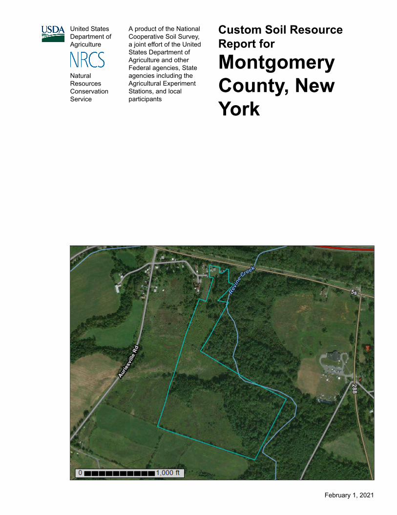
United StatesDepartment ofAgriculture
A product of the NationalCooperative Soil Survey,a joint effort of the UnitedStates Department ofAgriculture and otherFederal agencies, Stateagencies including theAgricultural ExperimentStations, and localparticipants
Custom Soil Resource Report for
Montgomery County, New York
NaturalResourcesConservationService
February 1, 2021

PrefaceSoil surveys contain information that affects land use planning in survey areas. They highlight soil limitations that affect various land uses and provide information about the properties of the soils in the survey areas. Soil surveys are designed for many different users, including farmers, ranchers, foresters, agronomists, urban planners, community officials, engineers, developers, builders, and home buyers. Also, conservationists, teachers, students, and specialists in recreation, waste disposal, and pollution control can use the surveys to help them understand, protect, or enhance the environment.
Various land use regulations of Federal, State, and local governments may impose special restrictions on land use or land treatment. Soil surveys identify soil properties that are used in making various land use or land treatment decisions. The information is intended to help the land users identify and reduce the effects of soil limitations on various land uses. The landowner or user is responsible for identifying and complying with existing laws and regulations.
Although soil survey information can be used for general farm, local, and wider area planning, onsite investigation is needed to supplement this information in some cases. Examples include soil quality assessments (http://www.nrcs.usda.gov/wps/portal/nrcs/main/soils/health/) and certain conservation and engineering applications. For more detailed information, contact your local USDA Service Center (https://offices.sc.egov.usda.gov/locator/app?agency=nrcs) or your NRCS State Soil Scientist (http://www.nrcs.usda.gov/wps/portal/nrcs/detail/soils/contactus/?cid=nrcs142p2_053951).
Great differences in soil properties can occur within short distances. Some soils are seasonally wet or subject to flooding. Some are too unstable to be used as a foundation for buildings or roads. Clayey or wet soils are poorly suited to use as septic tank absorption fields. A high water table makes a soil poorly suited to basements or underground installations.
The National Cooperative Soil Survey is a joint effort of the United States Department of Agriculture and other Federal agencies, State agencies including the Agricultural Experiment Stations, and local agencies. The Natural Resources Conservation Service (NRCS) has leadership for the Federal part of the National Cooperative Soil Survey.
Information about soils is updated periodically. Updated information is available through the NRCS Web Soil Survey, the site for official soil survey information.
The U.S. Department of Agriculture (USDA) prohibits discrimination in all its programs and activities on the basis of race, color, national origin, age, disability, and where applicable, sex, marital status, familial status, parental status, religion, sexual orientation, genetic information, political beliefs, reprisal, or because all or a part of an individual's income is derived from any public assistance program. (Not all prohibited bases apply to all programs.) Persons with disabilities who require
2

alternative means for communication of program information (Braille, large print, audiotape, etc.) should contact USDA's TARGET Center at (202) 720-2600 (voice and TDD). To file a complaint of discrimination, write to USDA, Director, Office of Civil Rights, 1400 Independence Avenue, S.W., Washington, D.C. 20250-9410 or call (800) 795-3272 (voice) or (202) 720-6382 (TDD). USDA is an equal opportunity provider and employer.
3
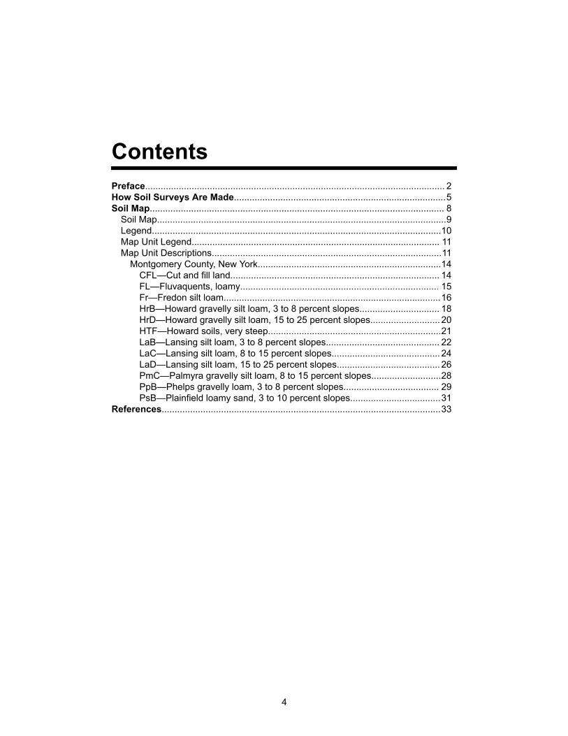
ContentsPreface.................................................................................................................... 2How Soil Surveys Are Made..................................................................................5Soil Map.................................................................................................................. 8
Soil Map................................................................................................................9Legend................................................................................................................10Map Unit Legend................................................................................................ 11Map Unit Descriptions.........................................................................................11
Montgomery County, New York.......................................................................14CFL—Cut and fill land................................................................................. 14FL—Fluvaquents, loamy............................................................................. 15Fr—Fredon silt loam....................................................................................16HrB—Howard gravelly silt loam, 3 to 8 percent slopes............................... 18HrD—Howard gravelly silt loam, 15 to 25 percent slopes........................... 20HTF—Howard soils, very steep...................................................................21LaB—Lansing silt loam, 3 to 8 percent slopes............................................ 22LaC—Lansing silt loam, 8 to 15 percent slopes.......................................... 24LaD—Lansing silt loam, 15 to 25 percent slopes........................................ 26PmC—Palmyra gravelly silt loam, 8 to 15 percent slopes...........................28PpB—Phelps gravelly loam, 3 to 8 percent slopes..................................... 29PsB—Plainfield loamy sand, 3 to 10 percent slopes...................................31
References............................................................................................................33
4
How Soil Surveys Are MadeSoil surveys are made to provide information about the soils and miscellaneous areas in a specific area. They include a description of the soils and miscellaneous areas and their location on the landscape and tables that show soil properties and limitations affecting various uses. Soil scientists observed the steepness, length, and shape of the slopes; the general pattern of drainage; the kinds of crops and native plants; and the kinds of bedrock. They observed and described many soil profiles. A soil profile is the sequence of natural layers, or horizons, in a soil. The profile extends from the surface down into the unconsolidated material in which the soil formed or from the surface down to bedrock. The unconsolidated material is devoid of roots and other living organisms and has not been changed by other biological activity.
Currently, soils are mapped according to the boundaries of major land resource areas (MLRAs). MLRAs are geographically associated land resource units that share common characteristics related to physiography, geology, climate, water resources, soils, biological resources, and land uses (USDA, 2006). Soil survey areas typically consist of parts of one or more MLRA.
The soils and miscellaneous areas in a survey area occur in an orderly pattern that is related to the geology, landforms, relief, climate, and natural vegetation of the area. Each kind of soil and miscellaneous area is associated with a particular kind of landform or with a segment of the landform. By observing the soils and miscellaneous areas in the survey area and relating their position to specific segments of the landform, a soil scientist develops a concept, or model, of how they were formed. Thus, during mapping, this model enables the soil scientist to predict with a considerable degree of accuracy the kind of soil or miscellaneous area at a specific location on the landscape.
Commonly, individual soils on the landscape merge into one another as their characteristics gradually change. To construct an accurate soil map, however, soil scientists must determine the boundaries between the soils. They can observe only a limited number of soil profiles. Nevertheless, these observations, supplemented by an understanding of the soil-vegetation-landscape relationship, are sufficient to verify predictions of the kinds of soil in an area and to determine the boundaries.
Soil scientists recorded the characteristics of the soil profiles that they studied. They noted soil color, texture, size and shape of soil aggregates, kind and amount of rock fragments, distribution of plant roots, reaction, and other features that enable them to identify soils. After describing the soils in the survey area and determining their properties, the soil scientists assigned the soils to taxonomic classes (units). Taxonomic classes are concepts. Each taxonomic class has a set of soil characteristics with precisely defined limits. The classes are used as a basis for comparison to classify soils systematically. Soil taxonomy, the system of taxonomic classification used in the United States, is based mainly on the kind and character of soil properties and the arrangement of horizons within the profile. After the soil
5
scientists classified and named the soils in the survey area, they compared the individual soils with similar soils in the same taxonomic class in other areas so that they could confirm data and assemble additional data based on experience and research.
The objective of soil mapping is not to delineate pure map unit components; the objective is to separate the landscape into landforms or landform segments that have similar use and management requirements. Each map unit is defined by a unique combination of soil components and/or miscellaneous areas in predictable proportions. Some components may be highly contrasting to the other components of the map unit. The presence of minor components in a map unit in no way diminishes the usefulness or accuracy of the data. The delineation of such landforms and landform segments on the map provides sufficient information for the development of resource plans. If intensive use of small areas is planned, onsite investigation is needed to define and locate the soils and miscellaneous areas.
Soil scientists make many field observations in the process of producing a soil map. The frequency of observation is dependent upon several factors, including scale of mapping, intensity of mapping, design of map units, complexity of the landscape, and experience of the soil scientist. Observations are made to test and refine the soil-landscape model and predictions and to verify the classification of the soils at specific locations. Once the soil-landscape model is refined, a significantly smaller number of measurements of individual soil properties are made and recorded. These measurements may include field measurements, such as those for color, depth to bedrock, and texture, and laboratory measurements, such as those for content of sand, silt, clay, salt, and other components. Properties of each soil typically vary from one point to another across the landscape.
Observations for map unit components are aggregated to develop ranges of characteristics for the components. The aggregated values are presented. Direct measurements do not exist for every property presented for every map unit component. Values for some properties are estimated from combinations of other properties.
While a soil survey is in progress, samples of some of the soils in the area generally are collected for laboratory analyses and for engineering tests. Soil scientists interpret the data from these analyses and tests as well as the field-observed characteristics and the soil properties to determine the expected behavior of the soils under different uses. Interpretations for all of the soils are field tested through observation of the soils in different uses and under different levels of management. Some interpretations are modified to fit local conditions, and some new interpretations are developed to meet local needs. Data are assembled from other sources, such as research information, production records, and field experience of specialists. For example, data on crop yields under defined levels of management are assembled from farm records and from field or plot experiments on the same kinds of soil.
Predictions about soil behavior are based not only on soil properties but also on such variables as climate and biological activity. Soil conditions are predictable over long periods of time, but they are not predictable from year to year. For example, soil scientists can predict with a fairly high degree of accuracy that a given soil will have a high water table within certain depths in most years, but they cannot predict that a high water table will always be at a specific level in the soil on a specific date.
After soil scientists located and identified the significant natural bodies of soil in the survey area, they drew the boundaries of these bodies on aerial photographs and
Custom Soil Resource Report
6

identified each as a specific map unit. Aerial photographs show trees, buildings, fields, roads, and rivers, all of which help in locating boundaries accurately.
Custom Soil Resource Report
7
Soil MapThe soil map section includes the soil map for the defined area of interest, a list of soil map units on the map and extent of each map unit, and cartographic symbols displayed on the map. Also presented are various metadata about data used to produce the map, and a description of each soil map unit.
8
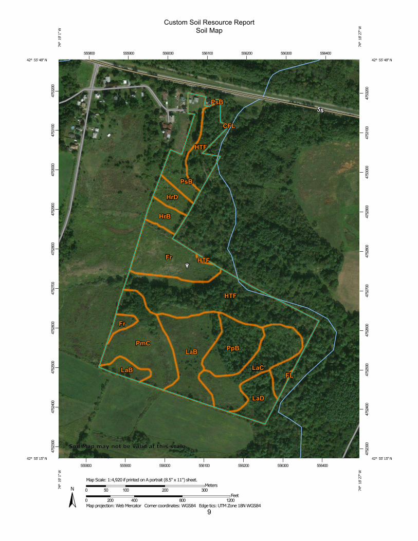
9
Custom Soil Resource ReportSoil Map
4752
300
4752
400
4752
500
4752
600
4752
700
4752
800
4752
900
4753
000
4753
100
4753
200
4752
300
4752
400
4752
500
4752
600
4752
700
4752
800
4752
900
4753
000
4753
100
4753
200
555800 555900 556000 556100 556200 556300 556400
555800 555900 556000 556100 556200 556300 556400
42° 55' 48'' N74
° 1
9' 1
'' W42° 55' 48'' N
74° 1
8' 2
7'' W
42° 55' 15'' N
74° 1
9' 1
'' W
42° 55' 15'' N
74° 1
8' 2
7'' W
N
Map projection: Web Mercator Corner coordinates: WGS84 Edge tics: UTM Zone 18N WGS840 200 400 800 1200
Feet0 50 100 200 300
MetersMap Scale: 1:4,920 if printed on A portrait (8.5" x 11") sheet.
Soil Map may not be valid at this scale.
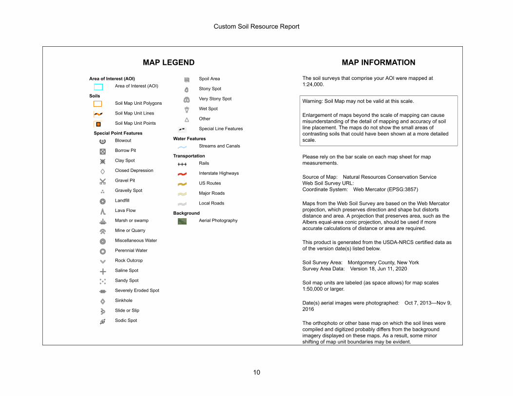
MAP LEGEND MAP INFORMATION
Area of Interest (AOI)Area of Interest (AOI)
SoilsSoil Map Unit Polygons
Soil Map Unit Lines
Soil Map Unit Points
Special Point FeaturesBlowout
Borrow Pit
Clay Spot
Closed Depression
Gravel Pit
Gravelly Spot
Landfill
Lava Flow
Marsh or swamp
Mine or Quarry
Miscellaneous Water
Perennial Water
Rock Outcrop
Saline Spot
Sandy Spot
Severely Eroded Spot
Sinkhole
Slide or Slip
Sodic Spot
Spoil Area
Stony Spot
Very Stony Spot
Wet Spot
Other
Special Line Features
Water FeaturesStreams and Canals
TransportationRails
Interstate Highways
US Routes
Major Roads
Local Roads
BackgroundAerial Photography
The soil surveys that comprise your AOI were mapped at 1:24,000.
Warning: Soil Map may not be valid at this scale.
Enlargement of maps beyond the scale of mapping can cause misunderstanding of the detail of mapping and accuracy of soil line placement. The maps do not show the small areas of contrasting soils that could have been shown at a more detailed scale.
Please rely on the bar scale on each map sheet for map measurements.
Source of Map: Natural Resources Conservation ServiceWeb Soil Survey URL: Coordinate System: Web Mercator (EPSG:3857)
Maps from the Web Soil Survey are based on the Web Mercator projection, which preserves direction and shape but distorts distance and area. A projection that preserves area, such as the Albers equal-area conic projection, should be used if more accurate calculations of distance or area are required.
This product is generated from the USDA-NRCS certified data as of the version date(s) listed below.
Soil Survey Area: Montgomery County, New YorkSurvey Area Data: Version 18, Jun 11, 2020
Soil map units are labeled (as space allows) for map scales 1:50,000 or larger.
Date(s) aerial images were photographed: Oct 7, 2013—Nov 9, 2016
The orthophoto or other base map on which the soil lines were compiled and digitized probably differs from the background imagery displayed on these maps. As a result, some minor shifting of map unit boundaries may be evident.
Custom Soil Resource Report
10
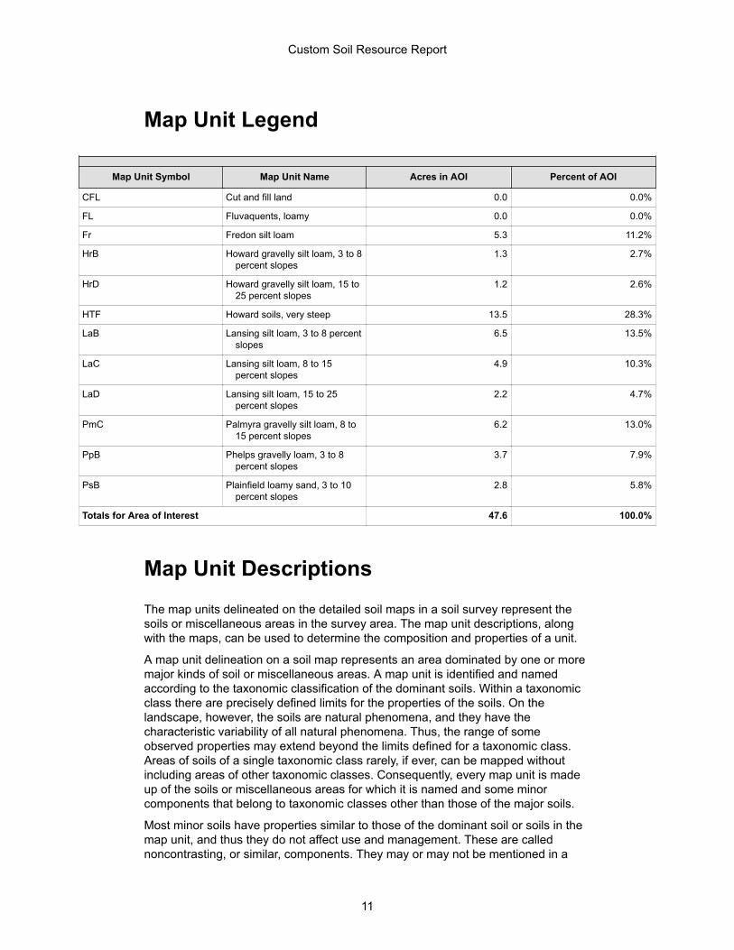
Map Unit Legend
Map Unit Symbol Map Unit Name Acres in AOI Percent of AOI
CFL Cut and fill land 0.0 0.0%
FL Fluvaquents, loamy 0.0 0.0%
Fr Fredon silt loam 5.3 11.2%
HrB Howard gravelly silt loam, 3 to 8 percent slopes
1.3 2.7%
HrD Howard gravelly silt loam, 15 to 25 percent slopes
1.2 2.6%
HTF Howard soils, very steep 13.5 28.3%
LaB Lansing silt loam, 3 to 8 percent slopes
6.5 13.5%
LaC Lansing silt loam, 8 to 15 percent slopes
4.9 10.3%
LaD Lansing silt loam, 15 to 25 percent slopes
2.2 4.7%
PmC Palmyra gravelly silt loam, 8 to 15 percent slopes
6.2 13.0%
PpB Phelps gravelly loam, 3 to 8 percent slopes
3.7 7.9%
PsB Plainfield loamy sand, 3 to 10 percent slopes
2.8 5.8%
Totals for Area of Interest 47.6 100.0%
Map Unit DescriptionsThe map units delineated on the detailed soil maps in a soil survey represent the soils or miscellaneous areas in the survey area. The map unit descriptions, along with the maps, can be used to determine the composition and properties of a unit.
A map unit delineation on a soil map represents an area dominated by one or more major kinds of soil or miscellaneous areas. A map unit is identified and named according to the taxonomic classification of the dominant soils. Within a taxonomic class there are precisely defined limits for the properties of the soils. On the landscape, however, the soils are natural phenomena, and they have the characteristic variability of all natural phenomena. Thus, the range of some observed properties may extend beyond the limits defined for a taxonomic class. Areas of soils of a single taxonomic class rarely, if ever, can be mapped without including areas of other taxonomic classes. Consequently, every map unit is made up of the soils or miscellaneous areas for which it is named and some minor components that belong to taxonomic classes other than those of the major soils.
Most minor soils have properties similar to those of the dominant soil or soils in the map unit, and thus they do not affect use and management. These are called noncontrasting, or similar, components. They may or may not be mentioned in a
Custom Soil Resource Report
11
particular map unit description. Other minor components, however, have properties and behavioral characteristics divergent enough to affect use or to require different management. These are called contrasting, or dissimilar, components. They generally are in small areas and could not be mapped separately because of the scale used. Some small areas of strongly contrasting soils or miscellaneous areas are identified by a special symbol on the maps. If included in the database for a given area, the contrasting minor components are identified in the map unit descriptions along with some characteristics of each. A few areas of minor components may not have been observed, and consequently they are not mentioned in the descriptions, especially where the pattern was so complex that it was impractical to make enough observations to identify all the soils and miscellaneous areas on the landscape.
The presence of minor components in a map unit in no way diminishes the usefulness or accuracy of the data. The objective of mapping is not to delineate pure taxonomic classes but rather to separate the landscape into landforms or landform segments that have similar use and management requirements. The delineation of such segments on the map provides sufficient information for the development of resource plans. If intensive use of small areas is planned, however, onsite investigation is needed to define and locate the soils and miscellaneous areas.
An identifying symbol precedes the map unit name in the map unit descriptions. Each description includes general facts about the unit and gives important soil properties and qualities.
Soils that have profiles that are almost alike make up a soil series. Except for differences in texture of the surface layer, all the soils of a series have major horizons that are similar in composition, thickness, and arrangement.
Soils of one series can differ in texture of the surface layer, slope, stoniness, salinity, degree of erosion, and other characteristics that affect their use. On the basis of such differences, a soil series is divided into soil phases. Most of the areas shown on the detailed soil maps are phases of soil series. The name of a soil phase commonly indicates a feature that affects use or management. For example, Alpha silt loam, 0 to 2 percent slopes, is a phase of the Alpha series.
Some map units are made up of two or more major soils or miscellaneous areas. These map units are complexes, associations, or undifferentiated groups.
A complex consists of two or more soils or miscellaneous areas in such an intricate pattern or in such small areas that they cannot be shown separately on the maps. The pattern and proportion of the soils or miscellaneous areas are somewhat similar in all areas. Alpha-Beta complex, 0 to 6 percent slopes, is an example.
An association is made up of two or more geographically associated soils or miscellaneous areas that are shown as one unit on the maps. Because of present or anticipated uses of the map units in the survey area, it was not considered practical or necessary to map the soils or miscellaneous areas separately. The pattern and relative proportion of the soils or miscellaneous areas are somewhat similar. Alpha-Beta association, 0 to 2 percent slopes, is an example.
An undifferentiated group is made up of two or more soils or miscellaneous areas that could be mapped individually but are mapped as one unit because similar interpretations can be made for use and management. The pattern and proportion of the soils or miscellaneous areas in a mapped area are not uniform. An area can be made up of only one of the major soils or miscellaneous areas, or it can be made up of all of them. Alpha and Beta soils, 0 to 2 percent slopes, is an example.
Custom Soil Resource Report
12

Some surveys include miscellaneous areas. Such areas have little or no soil material and support little or no vegetation. Rock outcrop is an example.
Custom Soil Resource Report
13
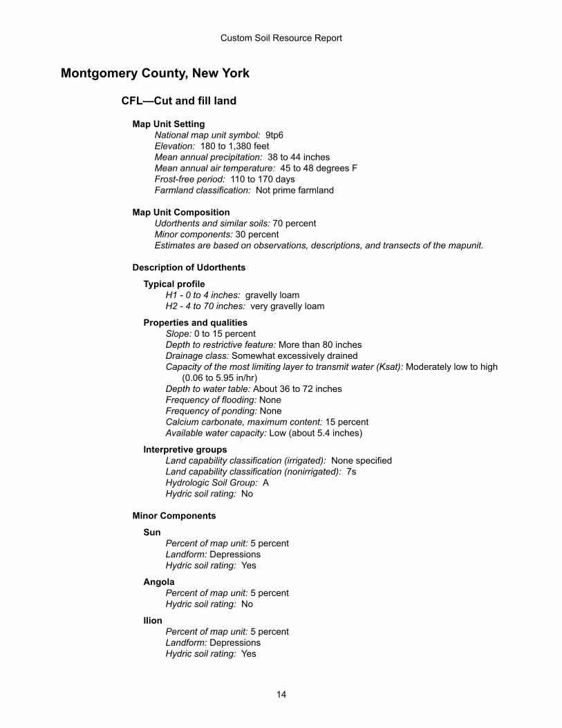
Montgomery County, New York
CFL—Cut and fill land
Map Unit SettingNational map unit symbol: 9tp6Elevation: 180 to 1,380 feetMean annual precipitation: 38 to 44 inchesMean annual air temperature: 45 to 48 degrees FFrost-free period: 110 to 170 daysFarmland classification: Not prime farmland
Map Unit CompositionUdorthents and similar soils: 70 percentMinor components: 30 percentEstimates are based on observations, descriptions, and transects of the mapunit.
Description of Udorthents
Typical profileH1 - 0 to 4 inches: gravelly loamH2 - 4 to 70 inches: very gravelly loam
Properties and qualitiesSlope: 0 to 15 percentDepth to restrictive feature: More than 80 inchesDrainage class: Somewhat excessively drainedCapacity of the most limiting layer to transmit water (Ksat): Moderately low to high
(0.06 to 5.95 in/hr)Depth to water table: About 36 to 72 inchesFrequency of flooding: NoneFrequency of ponding: NoneCalcium carbonate, maximum content: 15 percentAvailable water capacity: Low (about 5.4 inches)
Interpretive groupsLand capability classification (irrigated): None specifiedLand capability classification (nonirrigated): 7sHydrologic Soil Group: AHydric soil rating: No
Minor Components
SunPercent of map unit: 5 percentLandform: DepressionsHydric soil rating: Yes
AngolaPercent of map unit: 5 percentHydric soil rating: No
IlionPercent of map unit: 5 percentLandform: DepressionsHydric soil rating: Yes
Custom Soil Resource Report
14
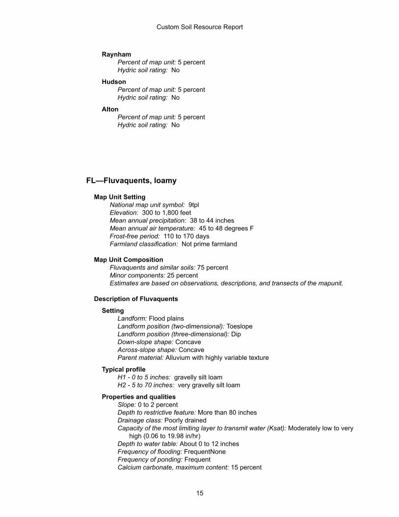
RaynhamPercent of map unit: 5 percentHydric soil rating: No
HudsonPercent of map unit: 5 percentHydric soil rating: No
AltonPercent of map unit: 5 percentHydric soil rating: No
FL—Fluvaquents, loamy
Map Unit SettingNational map unit symbol: 9tplElevation: 300 to 1,800 feetMean annual precipitation: 38 to 44 inchesMean annual air temperature: 45 to 48 degrees FFrost-free period: 110 to 170 daysFarmland classification: Not prime farmland
Map Unit CompositionFluvaquents and similar soils: 75 percentMinor components: 25 percentEstimates are based on observations, descriptions, and transects of the mapunit.
Description of Fluvaquents
SettingLandform: Flood plainsLandform position (two-dimensional): ToeslopeLandform position (three-dimensional): DipDown-slope shape: ConcaveAcross-slope shape: ConcaveParent material: Alluvium with highly variable texture
Typical profileH1 - 0 to 5 inches: gravelly silt loamH2 - 5 to 70 inches: very gravelly silt loam
Properties and qualitiesSlope: 0 to 2 percentDepth to restrictive feature: More than 80 inchesDrainage class: Poorly drainedCapacity of the most limiting layer to transmit water (Ksat): Moderately low to very
high (0.06 to 19.98 in/hr)Depth to water table: About 0 to 12 inchesFrequency of flooding: FrequentNoneFrequency of ponding: FrequentCalcium carbonate, maximum content: 15 percent
Custom Soil Resource Report
15
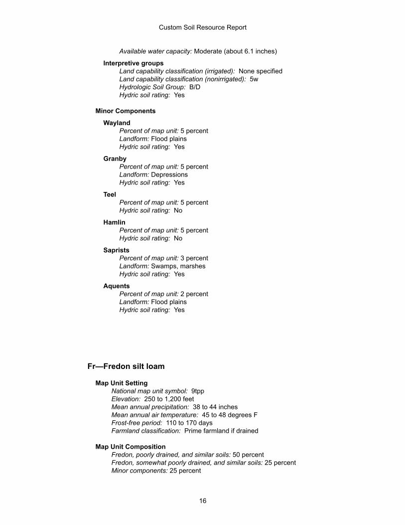
Available water capacity: Moderate (about 6.1 inches)
Interpretive groupsLand capability classification (irrigated): None specifiedLand capability classification (nonirrigated): 5wHydrologic Soil Group: B/DHydric soil rating: Yes
Minor Components
WaylandPercent of map unit: 5 percentLandform: Flood plainsHydric soil rating: Yes
GranbyPercent of map unit: 5 percentLandform: DepressionsHydric soil rating: Yes
TeelPercent of map unit: 5 percentHydric soil rating: No
HamlinPercent of map unit: 5 percentHydric soil rating: No
SapristsPercent of map unit: 3 percentLandform: Swamps, marshesHydric soil rating: Yes
AquentsPercent of map unit: 2 percentLandform: Flood plainsHydric soil rating: Yes
Fr—Fredon silt loam
Map Unit SettingNational map unit symbol: 9tppElevation: 250 to 1,200 feetMean annual precipitation: 38 to 44 inchesMean annual air temperature: 45 to 48 degrees FFrost-free period: 110 to 170 daysFarmland classification: Prime farmland if drained
Map Unit CompositionFredon, poorly drained, and similar soils: 50 percentFredon, somewhat poorly drained, and similar soils: 25 percentMinor components: 25 percent
Custom Soil Resource Report
16
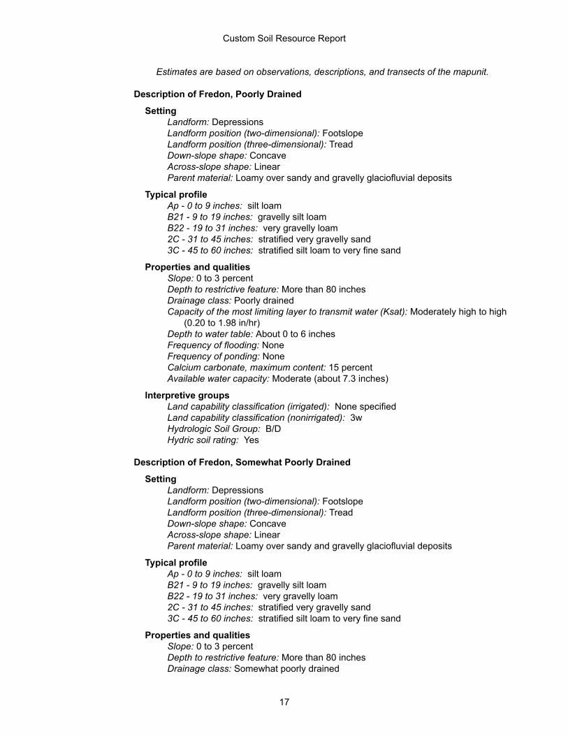
Estimates are based on observations, descriptions, and transects of the mapunit.
Description of Fredon, Poorly Drained
SettingLandform: DepressionsLandform position (two-dimensional): FootslopeLandform position (three-dimensional): TreadDown-slope shape: ConcaveAcross-slope shape: LinearParent material: Loamy over sandy and gravelly glaciofluvial deposits
Typical profileAp - 0 to 9 inches: silt loamB21 - 9 to 19 inches: gravelly silt loamB22 - 19 to 31 inches: very gravelly loam2C - 31 to 45 inches: stratified very gravelly sand3C - 45 to 60 inches: stratified silt loam to very fine sand
Properties and qualitiesSlope: 0 to 3 percentDepth to restrictive feature: More than 80 inchesDrainage class: Poorly drainedCapacity of the most limiting layer to transmit water (Ksat): Moderately high to high
(0.20 to 1.98 in/hr)Depth to water table: About 0 to 6 inchesFrequency of flooding: NoneFrequency of ponding: NoneCalcium carbonate, maximum content: 15 percentAvailable water capacity: Moderate (about 7.3 inches)
Interpretive groupsLand capability classification (irrigated): None specifiedLand capability classification (nonirrigated): 3wHydrologic Soil Group: B/DHydric soil rating: Yes
Description of Fredon, Somewhat Poorly Drained
SettingLandform: DepressionsLandform position (two-dimensional): FootslopeLandform position (three-dimensional): TreadDown-slope shape: ConcaveAcross-slope shape: LinearParent material: Loamy over sandy and gravelly glaciofluvial deposits
Typical profileAp - 0 to 9 inches: silt loamB21 - 9 to 19 inches: gravelly silt loamB22 - 19 to 31 inches: very gravelly loam2C - 31 to 45 inches: stratified very gravelly sand3C - 45 to 60 inches: stratified silt loam to very fine sand
Properties and qualitiesSlope: 0 to 3 percentDepth to restrictive feature: More than 80 inchesDrainage class: Somewhat poorly drained
Custom Soil Resource Report
17
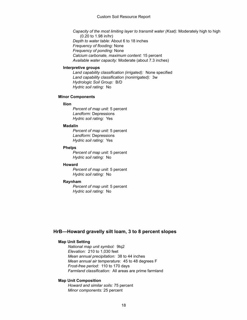
Capacity of the most limiting layer to transmit water (Ksat): Moderately high to high (0.20 to 1.98 in/hr)
Depth to water table: About 6 to 18 inchesFrequency of flooding: NoneFrequency of ponding: NoneCalcium carbonate, maximum content: 15 percentAvailable water capacity: Moderate (about 7.3 inches)
Interpretive groupsLand capability classification (irrigated): None specifiedLand capability classification (nonirrigated): 3wHydrologic Soil Group: B/DHydric soil rating: No
Minor Components
IlionPercent of map unit: 5 percentLandform: DepressionsHydric soil rating: Yes
MadalinPercent of map unit: 5 percentLandform: DepressionsHydric soil rating: Yes
PhelpsPercent of map unit: 5 percentHydric soil rating: No
HowardPercent of map unit: 5 percentHydric soil rating: No
RaynhamPercent of map unit: 5 percentHydric soil rating: No
HrB—Howard gravelly silt loam, 3 to 8 percent slopes
Map Unit SettingNational map unit symbol: 9tq2Elevation: 210 to 1,030 feetMean annual precipitation: 38 to 44 inchesMean annual air temperature: 45 to 48 degrees FFrost-free period: 110 to 170 daysFarmland classification: All areas are prime farmland
Map Unit CompositionHoward and similar soils: 75 percentMinor components: 25 percent
Custom Soil Resource Report
18
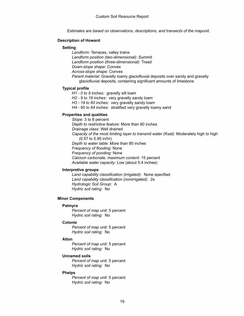
Estimates are based on observations, descriptions, and transects of the mapunit.
Description of Howard
SettingLandform: Terraces, valley trainsLandform position (two-dimensional): SummitLandform position (three-dimensional): TreadDown-slope shape: ConvexAcross-slope shape: ConvexParent material: Gravelly loamy glaciofluvial deposits over sandy and gravelly
glaciofluvial deposits, containing significant amounts of limestone
Typical profileH1 - 0 to 9 inches: gravelly silt loamH2 - 9 to 19 inches: very gravelly sandy loamH3 - 19 to 60 inches: very gravelly sandy loamH4 - 60 to 64 inches: stratified very gravelly loamy sand
Properties and qualitiesSlope: 3 to 8 percentDepth to restrictive feature: More than 80 inchesDrainage class: Well drainedCapacity of the most limiting layer to transmit water (Ksat): Moderately high to high
(0.57 to 5.95 in/hr)Depth to water table: More than 80 inchesFrequency of flooding: NoneFrequency of ponding: NoneCalcium carbonate, maximum content: 15 percentAvailable water capacity: Low (about 5.4 inches)
Interpretive groupsLand capability classification (irrigated): None specifiedLand capability classification (nonirrigated): 2sHydrologic Soil Group: AHydric soil rating: No
Minor Components
PalmyraPercent of map unit: 5 percentHydric soil rating: No
ColoniePercent of map unit: 5 percentHydric soil rating: No
AltonPercent of map unit: 5 percentHydric soil rating: No
Unnamed soilsPercent of map unit: 5 percentHydric soil rating: No
PhelpsPercent of map unit: 5 percentHydric soil rating: No
Custom Soil Resource Report
19
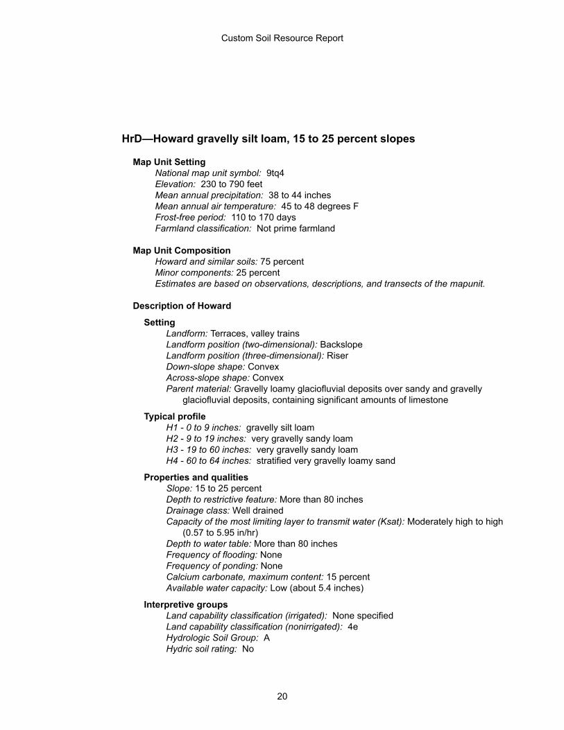
HrD—Howard gravelly silt loam, 15 to 25 percent slopes
Map Unit SettingNational map unit symbol: 9tq4Elevation: 230 to 790 feetMean annual precipitation: 38 to 44 inchesMean annual air temperature: 45 to 48 degrees FFrost-free period: 110 to 170 daysFarmland classification: Not prime farmland
Map Unit CompositionHoward and similar soils: 75 percentMinor components: 25 percentEstimates are based on observations, descriptions, and transects of the mapunit.
Description of Howard
SettingLandform: Terraces, valley trainsLandform position (two-dimensional): BackslopeLandform position (three-dimensional): RiserDown-slope shape: ConvexAcross-slope shape: ConvexParent material: Gravelly loamy glaciofluvial deposits over sandy and gravelly
glaciofluvial deposits, containing significant amounts of limestone
Typical profileH1 - 0 to 9 inches: gravelly silt loamH2 - 9 to 19 inches: very gravelly sandy loamH3 - 19 to 60 inches: very gravelly sandy loamH4 - 60 to 64 inches: stratified very gravelly loamy sand
Properties and qualitiesSlope: 15 to 25 percentDepth to restrictive feature: More than 80 inchesDrainage class: Well drainedCapacity of the most limiting layer to transmit water (Ksat): Moderately high to high
(0.57 to 5.95 in/hr)Depth to water table: More than 80 inchesFrequency of flooding: NoneFrequency of ponding: NoneCalcium carbonate, maximum content: 15 percentAvailable water capacity: Low (about 5.4 inches)
Interpretive groupsLand capability classification (irrigated): None specifiedLand capability classification (nonirrigated): 4eHydrologic Soil Group: AHydric soil rating: No
Custom Soil Resource Report
20
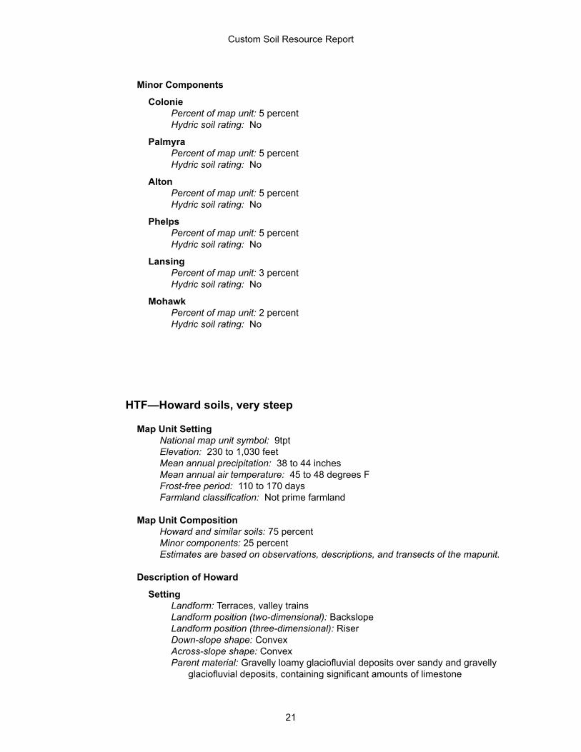
Minor Components
ColoniePercent of map unit: 5 percentHydric soil rating: No
PalmyraPercent of map unit: 5 percentHydric soil rating: No
AltonPercent of map unit: 5 percentHydric soil rating: No
PhelpsPercent of map unit: 5 percentHydric soil rating: No
LansingPercent of map unit: 3 percentHydric soil rating: No
MohawkPercent of map unit: 2 percentHydric soil rating: No
HTF—Howard soils, very steep
Map Unit SettingNational map unit symbol: 9tptElevation: 230 to 1,030 feetMean annual precipitation: 38 to 44 inchesMean annual air temperature: 45 to 48 degrees FFrost-free period: 110 to 170 daysFarmland classification: Not prime farmland
Map Unit CompositionHoward and similar soils: 75 percentMinor components: 25 percentEstimates are based on observations, descriptions, and transects of the mapunit.
Description of Howard
SettingLandform: Terraces, valley trainsLandform position (two-dimensional): BackslopeLandform position (three-dimensional): RiserDown-slope shape: ConvexAcross-slope shape: ConvexParent material: Gravelly loamy glaciofluvial deposits over sandy and gravelly
glaciofluvial deposits, containing significant amounts of limestone
Custom Soil Resource Report
21
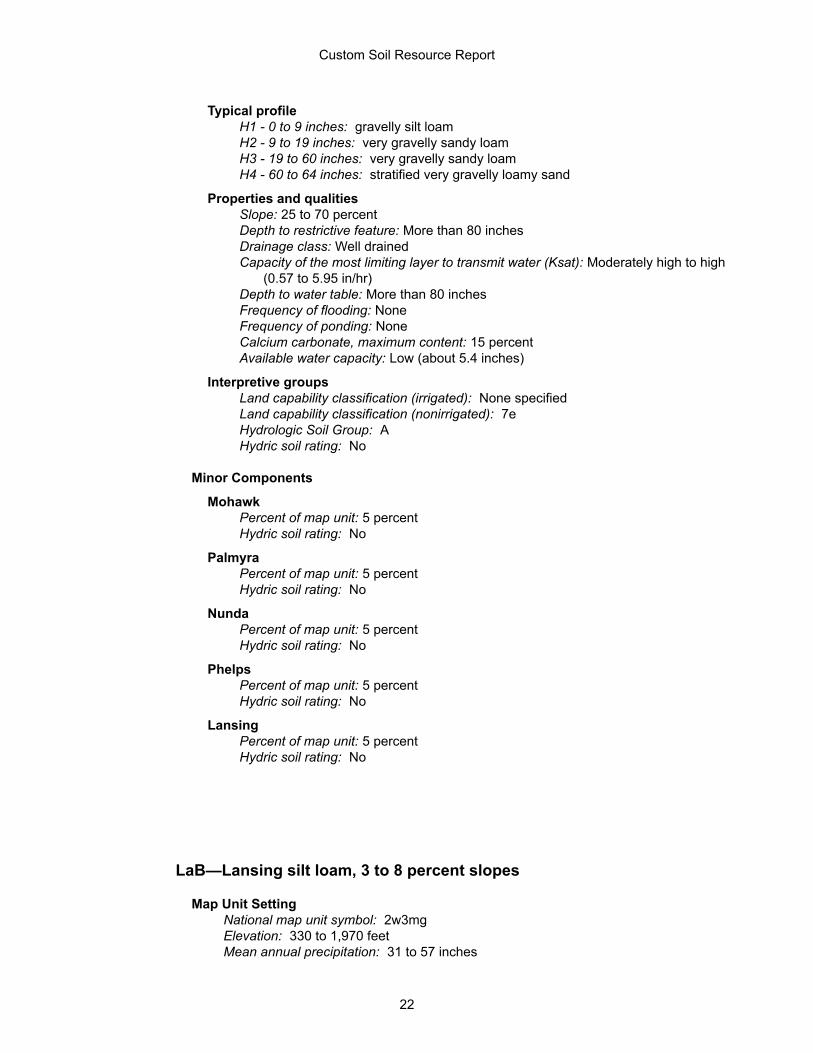
Typical profileH1 - 0 to 9 inches: gravelly silt loamH2 - 9 to 19 inches: very gravelly sandy loamH3 - 19 to 60 inches: very gravelly sandy loamH4 - 60 to 64 inches: stratified very gravelly loamy sand
Properties and qualitiesSlope: 25 to 70 percentDepth to restrictive feature: More than 80 inchesDrainage class: Well drainedCapacity of the most limiting layer to transmit water (Ksat): Moderately high to high
(0.57 to 5.95 in/hr)Depth to water table: More than 80 inchesFrequency of flooding: NoneFrequency of ponding: NoneCalcium carbonate, maximum content: 15 percentAvailable water capacity: Low (about 5.4 inches)
Interpretive groupsLand capability classification (irrigated): None specifiedLand capability classification (nonirrigated): 7eHydrologic Soil Group: AHydric soil rating: No
Minor Components
MohawkPercent of map unit: 5 percentHydric soil rating: No
PalmyraPercent of map unit: 5 percentHydric soil rating: No
NundaPercent of map unit: 5 percentHydric soil rating: No
PhelpsPercent of map unit: 5 percentHydric soil rating: No
LansingPercent of map unit: 5 percentHydric soil rating: No
LaB—Lansing silt loam, 3 to 8 percent slopes
Map Unit SettingNational map unit symbol: 2w3mgElevation: 330 to 1,970 feetMean annual precipitation: 31 to 57 inches
Custom Soil Resource Report
22
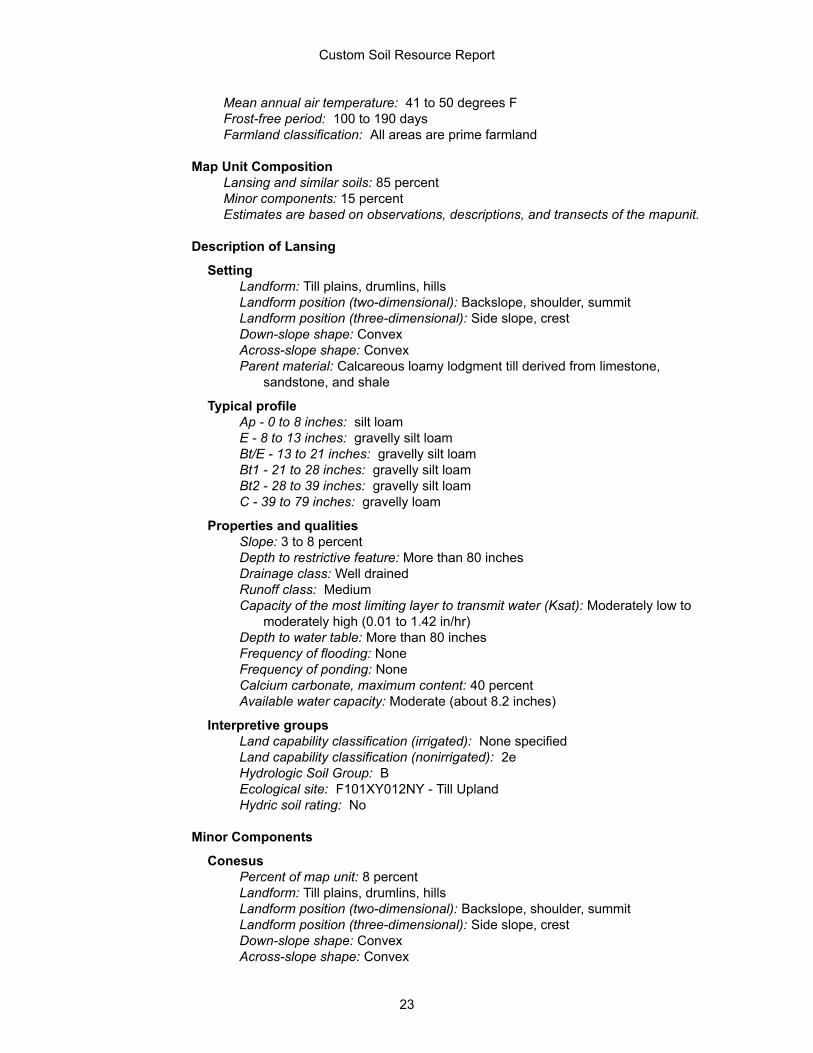
Mean annual air temperature: 41 to 50 degrees FFrost-free period: 100 to 190 daysFarmland classification: All areas are prime farmland
Map Unit CompositionLansing and similar soils: 85 percentMinor components: 15 percentEstimates are based on observations, descriptions, and transects of the mapunit.
Description of Lansing
SettingLandform: Till plains, drumlins, hillsLandform position (two-dimensional): Backslope, shoulder, summitLandform position (three-dimensional): Side slope, crestDown-slope shape: ConvexAcross-slope shape: ConvexParent material: Calcareous loamy lodgment till derived from limestone,
sandstone, and shale
Typical profileAp - 0 to 8 inches: silt loamE - 8 to 13 inches: gravelly silt loamBt/E - 13 to 21 inches: gravelly silt loamBt1 - 21 to 28 inches: gravelly silt loamBt2 - 28 to 39 inches: gravelly silt loamC - 39 to 79 inches: gravelly loam
Properties and qualitiesSlope: 3 to 8 percentDepth to restrictive feature: More than 80 inchesDrainage class: Well drainedRunoff class: MediumCapacity of the most limiting layer to transmit water (Ksat): Moderately low to
moderately high (0.01 to 1.42 in/hr)Depth to water table: More than 80 inchesFrequency of flooding: NoneFrequency of ponding: NoneCalcium carbonate, maximum content: 40 percentAvailable water capacity: Moderate (about 8.2 inches)
Interpretive groupsLand capability classification (irrigated): None specifiedLand capability classification (nonirrigated): 2eHydrologic Soil Group: BEcological site: F101XY012NY - Till UplandHydric soil rating: No
Minor Components
ConesusPercent of map unit: 8 percentLandform: Till plains, drumlins, hillsLandform position (two-dimensional): Backslope, shoulder, summitLandform position (three-dimensional): Side slope, crestDown-slope shape: ConvexAcross-slope shape: Convex
Custom Soil Resource Report
23
Hydric soil rating: No
KendaiaPercent of map unit: 3 percentLandform: Till plains, drumlinsLandform position (two-dimensional): FootslopeLandform position (three-dimensional): Base slopeDown-slope shape: ConcaveAcross-slope shape: LinearHydric soil rating: No
AppletonPercent of map unit: 2 percentLandform: Drumlins, till plainsLandform position (two-dimensional): FootslopeLandform position (three-dimensional): Base slopeDown-slope shape: ConcaveAcross-slope shape: LinearHydric soil rating: No
PalatinePercent of map unit: 1 percentLandform: Benches, ridgesLandform position (two-dimensional): SummitLandform position (three-dimensional): Crest, treadDown-slope shape: ConvexAcross-slope shape: ConvexHydric soil rating: No
DanleyPercent of map unit: 1 percentLandform: Till plains, drumlinoid ridges, hillsLandform position (two-dimensional): SummitLandform position (three-dimensional): CrestDown-slope shape: ConvexAcross-slope shape: ConvexHydric soil rating: No
LaC—Lansing silt loam, 8 to 15 percent slopes
Map Unit SettingNational map unit symbol: 2w3mhElevation: 330 to 2,130 feetMean annual precipitation: 31 to 57 inchesMean annual air temperature: 41 to 50 degrees FFrost-free period: 100 to 190 daysFarmland classification: Farmland of statewide importance
Map Unit CompositionLansing and similar soils: 85 percentMinor components: 15 percent
Custom Soil Resource Report
24
Estimates are based on observations, descriptions, and transects of the mapunit.
Description of Lansing
SettingLandform: Till plains, drumlins, hillsLandform position (two-dimensional): Summit, shoulder, backslopeLandform position (three-dimensional): Crest, side slopeDown-slope shape: ConvexAcross-slope shape: ConvexParent material: Calcareous loamy lodgment till derived from limestone,
sandstone, and shale
Typical profileAp - 0 to 8 inches: silt loamE - 8 to 13 inches: gravelly silt loamBt/E - 13 to 21 inches: gravelly silt loamBt1 - 21 to 28 inches: gravelly silt loamBt2 - 28 to 39 inches: gravelly silt loamC - 39 to 79 inches: gravelly loam
Properties and qualitiesSlope: 8 to 15 percentDepth to restrictive feature: More than 80 inchesDrainage class: Well drainedRunoff class: MediumCapacity of the most limiting layer to transmit water (Ksat): Moderately low to
moderately high (0.01 to 1.42 in/hr)Depth to water table: More than 80 inchesFrequency of flooding: NoneFrequency of ponding: NoneCalcium carbonate, maximum content: 40 percentAvailable water capacity: Moderate (about 8.2 inches)
Interpretive groupsLand capability classification (irrigated): None specifiedLand capability classification (nonirrigated): 3eHydrologic Soil Group: BEcological site: F101XY012NY - Till UplandHydric soil rating: No
Minor Components
ConesusPercent of map unit: 8 percentLandform: Till plains, drumlins, hillsLandform position (two-dimensional): Summit, shoulderLandform position (three-dimensional): CrestDown-slope shape: LinearAcross-slope shape: ConvexHydric soil rating: No
KendaiaPercent of map unit: 3 percentLandform: Till plains, drumlinsLandform position (two-dimensional): FootslopeLandform position (three-dimensional): Base slope
Custom Soil Resource Report
25
Down-slope shape: ConcaveAcross-slope shape: LinearHydric soil rating: No
AppletonPercent of map unit: 2 percentLandform: Drumlins, till plainsLandform position (two-dimensional): FootslopeLandform position (three-dimensional): Base slopeDown-slope shape: ConcaveAcross-slope shape: LinearHydric soil rating: No
DanleyPercent of map unit: 1 percentLandform: Hills, till plains, drumlinoid ridgesLandform position (two-dimensional): SummitLandform position (three-dimensional): CrestDown-slope shape: ConvexAcross-slope shape: ConvexHydric soil rating: No
WassaicPercent of map unit: 1 percentLandform: Till plains, benches, ridgesLandform position (two-dimensional): SummitLandform position (three-dimensional): CrestDown-slope shape: ConvexAcross-slope shape: ConvexHydric soil rating: No
LaD—Lansing silt loam, 15 to 25 percent slopes
Map Unit SettingNational map unit symbol: 2w3mfElevation: 660 to 1,740 feetMean annual precipitation: 31 to 57 inchesMean annual air temperature: 41 to 50 degrees FFrost-free period: 100 to 190 daysFarmland classification: Not prime farmland
Map Unit CompositionLansing and similar soils: 85 percentMinor components: 15 percentEstimates are based on observations, descriptions, and transects of the mapunit.
Description of Lansing
SettingLandform: Till plains, drumlins, hillsLandform position (two-dimensional): Backslope
Custom Soil Resource Report
26
Landform position (three-dimensional): Side slopeDown-slope shape: ConvexAcross-slope shape: ConvexParent material: Calcareous loamy lodgment till derived from limestone,
sandstone, and shale
Typical profileAp - 0 to 8 inches: silt loamE - 8 to 13 inches: gravelly silt loamBt/E - 13 to 21 inches: gravelly silt loamBt1 - 21 to 28 inches: gravelly silt loamBt2 - 28 to 39 inches: gravelly silt loamC - 39 to 79 inches: gravelly loam
Properties and qualitiesSlope: 15 to 25 percentDepth to restrictive feature: More than 80 inchesDrainage class: Well drainedRunoff class: MediumCapacity of the most limiting layer to transmit water (Ksat): Moderately low to
moderately high (0.01 to 1.42 in/hr)Depth to water table: More than 80 inchesFrequency of flooding: NoneFrequency of ponding: NoneCalcium carbonate, maximum content: 40 percentAvailable water capacity: Moderate (about 8.2 inches)
Interpretive groupsLand capability classification (irrigated): None specifiedLand capability classification (nonirrigated): 4eHydrologic Soil Group: BEcological site: F101XY012NY - Till UplandHydric soil rating: No
Minor Components
ConesusPercent of map unit: 9 percentLandform: Till plains, drumlins, hillsLandform position (two-dimensional): BackslopeLandform position (three-dimensional): Side slopeDown-slope shape: LinearAcross-slope shape: ConvexHydric soil rating: No
WassaicPercent of map unit: 3 percentLandform: Till plains, benches, ridgesLandform position (two-dimensional): SummitLandform position (three-dimensional): CrestDown-slope shape: ConvexAcross-slope shape: ConvexHydric soil rating: No
KendaiaPercent of map unit: 2 percentLandform: Till plains, drumlins
Custom Soil Resource Report
27
Landform position (two-dimensional): FootslopeLandform position (three-dimensional): Base slopeDown-slope shape: ConcaveAcross-slope shape: LinearHydric soil rating: No
AppletonPercent of map unit: 1 percentLandform: Till plains, drumlinsLandform position (two-dimensional): FootslopeLandform position (three-dimensional): Base slopeDown-slope shape: ConcaveAcross-slope shape: LinearHydric soil rating: No
PmC—Palmyra gravelly silt loam, 8 to 15 percent slopes
Map Unit SettingNational map unit symbol: 9trlElevation: 330 to 660 feetMean annual precipitation: 38 to 44 inchesMean annual air temperature: 45 to 48 degrees FFrost-free period: 110 to 170 daysFarmland classification: Farmland of statewide importance
Map Unit CompositionPalmyra and similar soils: 75 percentMinor components: 25 percentEstimates are based on observations, descriptions, and transects of the mapunit.
Description of Palmyra
SettingLandform: Outwash plains, terraces, deltasLandform position (two-dimensional): ShoulderLandform position (three-dimensional): TreadDown-slope shape: ConvexAcross-slope shape: ConvexParent material: Loamy over sandy and gravelly glaciofluvial deposits, derived
mainly from limestone and other sedimentary rocks
Typical profileH1 - 0 to 9 inches: gravelly silt loamH2 - 9 to 21 inches: gravelly loamH3 - 21 to 60 inches: stratified very gravelly sand
Properties and qualitiesSlope: 8 to 15 percentDepth to restrictive feature: More than 80 inchesDrainage class: Well drained
Custom Soil Resource Report
28
Capacity of the most limiting layer to transmit water (Ksat): Moderately high to high (0.57 to 5.95 in/hr)
Depth to water table: More than 80 inchesFrequency of flooding: NoneFrequency of ponding: NoneCalcium carbonate, maximum content: 15 percentAvailable water capacity: Low (about 3.6 inches)
Interpretive groupsLand capability classification (irrigated): None specifiedLand capability classification (nonirrigated): 3eHydrologic Soil Group: AHydric soil rating: No
Minor Components
PhelpsPercent of map unit: 5 percentHydric soil rating: No
HowardPercent of map unit: 5 percentHydric soil rating: No
HamlinPercent of map unit: 5 percentHydric soil rating: No
UnadillaPercent of map unit: 5 percentHydric soil rating: No
AltonPercent of map unit: 5 percentHydric soil rating: No
PpB—Phelps gravelly loam, 3 to 8 percent slopes
Map Unit SettingNational map unit symbol: 9trnElevation: 250 to 750 feetMean annual precipitation: 38 to 44 inchesMean annual air temperature: 45 to 48 degrees FFrost-free period: 110 to 170 daysFarmland classification: All areas are prime farmland
Map Unit CompositionPhelps and similar soils: 75 percentMinor components: 25 percentEstimates are based on observations, descriptions, and transects of the mapunit.
Custom Soil Resource Report
29
Description of Phelps
SettingLandform: Terraces, valley trainsLandform position (two-dimensional): SummitLandform position (three-dimensional): TreadDown-slope shape: ConcaveAcross-slope shape: ConvexParent material: Loamy glaciofluvial deposits over sandy and gravelly glaciofluvial
deposits, containing significant amounts of limestone
Typical profileH1 - 0 to 7 inches: gravelly loamH2 - 7 to 13 inches: gravelly silt loamH3 - 13 to 25 inches: gravelly silt loamH4 - 25 to 35 inches: gravelly silt loamH5 - 35 to 60 inches: stratified very gravelly sand
Properties and qualitiesSlope: 3 to 8 percentDepth to restrictive feature: More than 80 inchesDrainage class: Moderately well drainedCapacity of the most limiting layer to transmit water (Ksat): Moderately high to high
(0.57 to 1.98 in/hr)Depth to water table: About 18 to 24 inchesFrequency of flooding: NoneFrequency of ponding: NoneCalcium carbonate, maximum content: 15 percentAvailable water capacity: Low (about 5.0 inches)
Interpretive groupsLand capability classification (irrigated): None specifiedLand capability classification (nonirrigated): 2eHydrologic Soil Group: B/DHydric soil rating: No
Minor Components
CopakePercent of map unit: 5 percentHydric soil rating: No
PalmyraPercent of map unit: 5 percentHydric soil rating: No
HowardPercent of map unit: 5 percentHydric soil rating: No
TeelPercent of map unit: 5 percentHydric soil rating: No
ScioPercent of map unit: 5 percentHydric soil rating: No
Custom Soil Resource Report
30
PsB—Plainfield loamy sand, 3 to 10 percent slopes
Map Unit SettingNational map unit symbol: 9trrElevation: 720 to 1,150 feetMean annual precipitation: 38 to 44 inchesMean annual air temperature: 45 to 48 degrees FFrost-free period: 110 to 170 daysFarmland classification: Not prime farmland
Map Unit CompositionPlainfield and similar soils: 80 percentMinor components: 20 percentEstimates are based on observations, descriptions, and transects of the mapunit.
Description of Plainfield
SettingLandform: Outwash plains, terraces, deltasLandform position (two-dimensional): SummitLandform position (three-dimensional): TreadDown-slope shape: ConvexAcross-slope shape: ConvexParent material: Sandy glaciofluvial or deltaic deposits
Typical profileH1 - 0 to 8 inches: loamy sandH2 - 8 to 32 inches: coarse sandH3 - 32 to 78 inches: coarse sand
Properties and qualitiesSlope: 3 to 10 percentDepth to restrictive feature: More than 80 inchesDrainage class: Excessively drainedCapacity of the most limiting layer to transmit water (Ksat): High to very high (5.95
to 19.98 in/hr)Depth to water table: More than 80 inchesFrequency of flooding: NoneFrequency of ponding: NoneAvailable water capacity: Low (about 3.7 inches)
Interpretive groupsLand capability classification (irrigated): None specifiedLand capability classification (nonirrigated): 3sHydrologic Soil Group: AEcological site: F144AY022MA - Dry OutwashHydric soil rating: No
Custom Soil Resource Report
31
Minor Components
OtisvillePercent of map unit: 5 percentHydric soil rating: No
ColoniePercent of map unit: 5 percentHydric soil rating: No
AltonPercent of map unit: 5 percentHydric soil rating: No
ElnoraPercent of map unit: 5 percentHydric soil rating: No
Custom Soil Resource Report
32
ReferencesAmerican Association of State Highway and Transportation Officials (AASHTO). 2004. Standard specifications for transportation materials and methods of sampling and testing. 24th edition.
American Society for Testing and Materials (ASTM). 2005. Standard classification of soils for engineering purposes. ASTM Standard D2487-00.
Cowardin, L.M., V. Carter, F.C. Golet, and E.T. LaRoe. 1979. Classification of wetlands and deep-water habitats of the United States. U.S. Fish and Wildlife Service FWS/OBS-79/31.
Federal Register. July 13, 1994. Changes in hydric soils of the United States.
Federal Register. September 18, 2002. Hydric soils of the United States.
Hurt, G.W., and L.M. Vasilas, editors. Version 6.0, 2006. Field indicators of hydric soils in the United States.
National Research Council. 1995. Wetlands: Characteristics and boundaries.
Soil Survey Division Staff. 1993. Soil survey manual. Soil Conservation Service. U.S. Department of Agriculture Handbook 18. http://www.nrcs.usda.gov/wps/portal/nrcs/detail/national/soils/?cid=nrcs142p2_054262
Soil Survey Staff. 1999. Soil taxonomy: A basic system of soil classification for making and interpreting soil surveys. 2nd edition. Natural Resources Conservation Service, U.S. Department of Agriculture Handbook 436. http://www.nrcs.usda.gov/wps/portal/nrcs/detail/national/soils/?cid=nrcs142p2_053577
Soil Survey Staff. 2010. Keys to soil taxonomy. 11th edition. U.S. Department of Agriculture, Natural Resources Conservation Service. http://www.nrcs.usda.gov/wps/portal/nrcs/detail/national/soils/?cid=nrcs142p2_053580
Tiner, R.W., Jr. 1985. Wetlands of Delaware. U.S. Fish and Wildlife Service and Delaware Department of Natural Resources and Environmental Control, Wetlands Section.
United States Army Corps of Engineers, Environmental Laboratory. 1987. Corps of Engineers wetlands delineation manual. Waterways Experiment Station Technical Report Y-87-1.
United States Department of Agriculture, Natural Resources Conservation Service. National forestry manual. http://www.nrcs.usda.gov/wps/portal/nrcs/detail/soils/home/?cid=nrcs142p2_053374
United States Department of Agriculture, Natural Resources Conservation Service. National range and pasture handbook. http://www.nrcs.usda.gov/wps/portal/nrcs/detail/national/landuse/rangepasture/?cid=stelprdb1043084
33

United States Department of Agriculture, Natural Resources Conservation Service. National soil survey handbook, title 430-VI. http://www.nrcs.usda.gov/wps/portal/nrcs/detail/soils/scientists/?cid=nrcs142p2_054242
United States Department of Agriculture, Natural Resources Conservation Service. 2006. Land resource regions and major land resource areas of the United States, the Caribbean, and the Pacific Basin. U.S. Department of Agriculture Handbook 296. http://www.nrcs.usda.gov/wps/portal/nrcs/detail/national/soils/?cid=nrcs142p2_053624
United States Department of Agriculture, Soil Conservation Service. 1961. Land capability classification. U.S. Department of Agriculture Handbook 210. http://www.nrcs.usda.gov/Internet/FSE_DOCUMENTS/nrcs142p2_052290.pdf
Custom Soil Resource Report
34


![APPENDIX 19 - ~:: West Bengal Audit & Account Service · PART I] THE KOLKATA GAZETTE, EXTRAORDINARY, JUNE 14, 2005 305 APPENDIX 19 [See TR 4.090 (10)] NOTIFICATION ... after due acknowledgement,](https://img.pdfslide.us/doc/110x75/5af826457f8b9a44658bfd14/appendix-19-west-bengal-audit-account-i-the-kolkata-gazette-extraordinary.jpg)