Embed Size (px)
Citation preview

RC DISInfrastructure, environment, buildings
General Electric Company
Stormwater Pollution Prevention Plan
June 2009
ARCADlS
Stormwater PollutionPrevention Plan
Prepared lor:
General Electric Company
Pittsfield, Massachusetts
Prepared by:
ARCADIS
6723 Towpath Road
P.O. Box 66
Syracuse
New York 13214-0066
Tel 315.446.9120
Fax 315.449.0017
Our ReI.:
B0030124
Date:
June 2009

ARCADIS
1. Introduction 1
1.1 Background
1.2 Plan Organization 4
1.3 Facility Information 4
1.3.1 Site Operations and Buildings 5
1.3.2 Site Access 6
1.3.3 Storm Sewer Mapping 6
1.4 Stormwater Pollution Prevention Team (PPl) 6
1.4.1 Emergency Coordinators 9
2. Potential Pollutant Sources 10
2.1 Drainage Area Descriptions 10
2.1.1 Drainage Area 005 10
2.1.2 Drainage Area 006 10
2.1.3 Drainage Area 009 11
2.1.4 Drainage Area YD1 0 11
2.1.5 Drainage Area YD11 11
2.1.6 Drainage Area YD12 12
2.1.7 Drainage Area YD13 12
2.1.8 Drainage Area YD16 12
2.2 Identification of Pollutants and Potential Pollutant Sources 13
2.3 Non-Stormwater Discharges 17
2.3.1 Completed Dry Weather Flow-Related Activities 17
2.3.2 On-going Dry Weather Flow-Related Activities 18
2.3.3 Potential Future Dry Weather Flow-Related Activities 18
3. Stormwater Control Measures 19
3.1 Non-Numeric Technology-Based Controls 19
3.1.1 Good Housekeeping 19
Table of Contents
ARCADIS
3.1.2 Employee Training 20
3.1.3 Site Security 21
3.1.4 Preventive Maintenance 22
3.1.5 Spill Prevention and Response Procedures 22
3.1.6 Incident Reporting 23
3.1.7 Recordkeeping and Internal Reporting 24
3.1.8 Sedimentation and Erosion Control 25
3.2 Stormwater Management Controls 25
3.2.1 Drainage Area 005 26
3.2.2 Drainage Area 006 26
3.2.3 Drainage Area 009 27
3.2.4 Drainage Area YD1 0 27
3.2.5 Drainage Area YD11 27
3.2.6 Drainage Area YD12 28
3.2.7 Drainage Areas YD13 and YD16 28
4. Schedules and Procedures for Monitoring 29
4.1 Sampling 29
4.1.1 Sample Locations 29
4.1.2 Pollutant Parameters to be Sampled 31
4.1.3 Monitoring Schedule 31
4.1.4 Sampling Procedure 31
4.1.5 Weather Event Specifications 32
4.1.6 Required Sample Bottles 32
4.1.7 Sample Preservation 32
4.2 Recordkeeping 33
4.2.1 Reporting Requirements 33
Table of Contents
ii
AHeADIS
5. Inspections 34
5.1 Routine Inspections 34
5.1.1 Routine Inspection Procedures 34
5.2 Site Compliance Evaluation Procedures 34
6. SWPPP Certifications 34
6.1 Facility Management Certification 34
6.2 Site Compliance Evaluation Certification 34
7. SWPPP Modifications 34
7.1 Corrective Action(s) 34
7.1.1 Corrective Action Report 34
8. References 34
Tables
Table of Contents
Table 1-1
Table 1-2
Table 2-1
Table 5-1
Figure
Figure 1-1
Appendices
Appendix A
Appendix B
AppendixC
Appendix D
Appendix E
Listing of Monitored Outfalls
Pollution Prevention Team
Site Activity and Potential Pollutant Sources
Site Inspections
General Location Map
NPDES Permit No. MA 003891
Site Drainage Plans
Employee Training
Inspection Reports and Corrective Actions
Description of Reportable Quantity (RQ) Releases
iii
AHeADIS
BMPs
CEP
DMRs
EPA
EPCRA
ESA
GE
gpm
GWTP
MHC
MSGP
NHPA
NOI
NOT
NPDES
NRC
OPCA
OWS
PCB
PEDA
POP
best management practices
Corporate Environmental Programs
Discharge Monitoring Reports
United States Environmental Protection Agency
Emergency Planning & Community Right-To-Know Act
Endangered Species Act
square feet
General Electric Company
gallons per minute
Groundwater Treatment Plant
Massachusetts Historic Commission
Multi-Sector General Permit
National Historic Preservation Act
Notice of Intent
Notice of Termination
National Pollutant Discharge Elimination System
National Response Center
On-Plant Consolidation Area
OillWater Separator
polychlorinated biphenyl
Pittsfield Economic Development Authority
Project Operation Plan
Acronyms
ARCADIS Acronyms
R&D research and development
RQ Reportable Quantities
SIC Standard Industrial Classification
SPCC Plan Spill Prevention, Control and Countermeasure Plan
SSPS South Side Pump Station
SWPPP Stormwater Pollution Prevention Plan
WTP Water Treatment Plant
USFWS U.S. Fish and Wildlife Service
ii

ARCADIS
1. Introduction
Stormwater PollutionPrevention Plan
General Electric CompanyPittsfield, Massachusetts
This Stormwater Pollution Prevention Plan (SWPPP) addresses stormwater runoff areasdischarging to point sources authorized by NPDES Permit No. MA0003891 (NPDESPermit) for the General Electric Company's facility in Pittsfield, Massachusetts (see Figure1-1 for a General Location Map). This SWPPP incorporates the requirements set forth inPart I.C. of the NPDES Permit, including those incorporated through a reference to Section4 of EPA's Multi-Sector General Permit (MSGP), which was issued on October 30,2000.1
1.1 Background
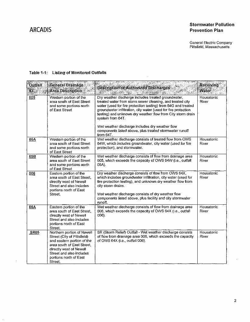
Prior to October 1, 1992, GE submitted an Individual NPDES permit application to the EPAfor stormwater discharges at its Pittsfield facility subject to the stormwater dischargeregulations. No action was taken on the application by EPA until February 15, 1994, whenthe agency issued a letter to GE stating that Baseline General Permit coverage wasrecommended. In 1994, GE submitted a Notice of Intent (NOI) for coverage under theBaseline General Permit. However, after GE was issued a Multi-Sector General Permit forStormwater Discharges Associated with Industrial Activity (MSGP) (MAR05A021) inSeptember of 1995, GE filed a Notice of Termination (NOT) to terminate coverage underthe Baseline General Permit in favor of obtaining coverage under the MSGP. On January26, 2001, GE submitted an NOI to continue coverage under the 2000 MSGP, and EPAissued a new MSGP (MAR05C102) that became effective on April 4, 2001. The 2000MSGP expired on October 30, 2005, but remained in force and effect until September 30,2008 when EPA issued the final NPDES Permit for the facility. The current NPDES Permitintegrates stormwater discharges from select outfalls previously covered under GE'sMSGP, as well as those outfalls identified under GE's individual NPDES Permit. A list of allmonitored outfalls included in the NPDES Permit, with information pertaining to each outfall,is provided in Table 1-1 below.
1 We note that EPA Region 1 and Massachusetts Department of Environmental Protection have
recently issued a proposed major modification to the NPDES Permit that, among other things, would
change this reference from Section 4 of the 2000 MSGP to Section 5 of the latest MSGP, which EPA
issued on September 29, 2008. This SWPPP meets the applicable requirements of both the 2000
and 2008 MSGPs.
ARCADIS
Table 1-1: Listing of Monitored Outfalls
Stormwater PollutionPrevention Plan
General Electric CompanyPittsfield, Massachusetts
Western portion of thearea south of East Streetand some portions northof East Street
Western portion of thearea south of East Streetand some portions northof East StreetWestern portion of thearea south of East Streetand some portions northof East StreetEastern portion of thearea south of East Street,directly west of NewellStreet and also includesportions north of EastStreet.
Eastern portion of thearea south of East Street,directly west of NewellStreet and also includesportions north of EastStreet.Northern portion of NewellStreet (City of Pittsfield)and eastern portion of thearea south of East Street,directly west of NewellStreet and also includesportions north of EastStreet.
Dry weather discharge includes treated groundwater,treated water from storm sewer cleaning, and treated citywater (used for fire protection testing) from 64G and treatedgroundwater infiltration, city water (used for fire protectiontesting) and unknown dry weather flow from City storm drainsystem from 64T.
Wet weather discharge includes dry weather flowcomponents listed above, plus treated stormwater runofffrom 641.Wet weather discharge consists of treated flow from OWS64W, which includes groundwater, city water (used for fireprotection), and stormwater.
Wet weather discharge consists of flow from drainage area005, which exceeds the capacity of OWS 64W (Le., outfall05A).
Dry weather discharge consists of flow from OWS 64X,which includes groundwater infiltration, city water (used forfire protection testing), and unknown dry weather flow fromcity storm drains.
Wet weather discharge consists of dry weather flowcomponents listed above, plus facility and city stormwaterrunoff.Wet weather discharge consists of flow from drainage area006, which exceeds the capacity of OWS 64X (i.e., outfall006).
SR (Storm Relief) Outfall - Wet weather discharge consistsof flow from drainage area 006, which exceeds the capacityof OWS 64X (Le., outfall 006).
HousatonicRiver
HousatonicRiver
HousatonicRiver
HousatonicRiver
HousatonicRiver
2
ARCADJSStormwater PollutionPrevention Plan
General Electric CompanyPittsfield, Massachusetts
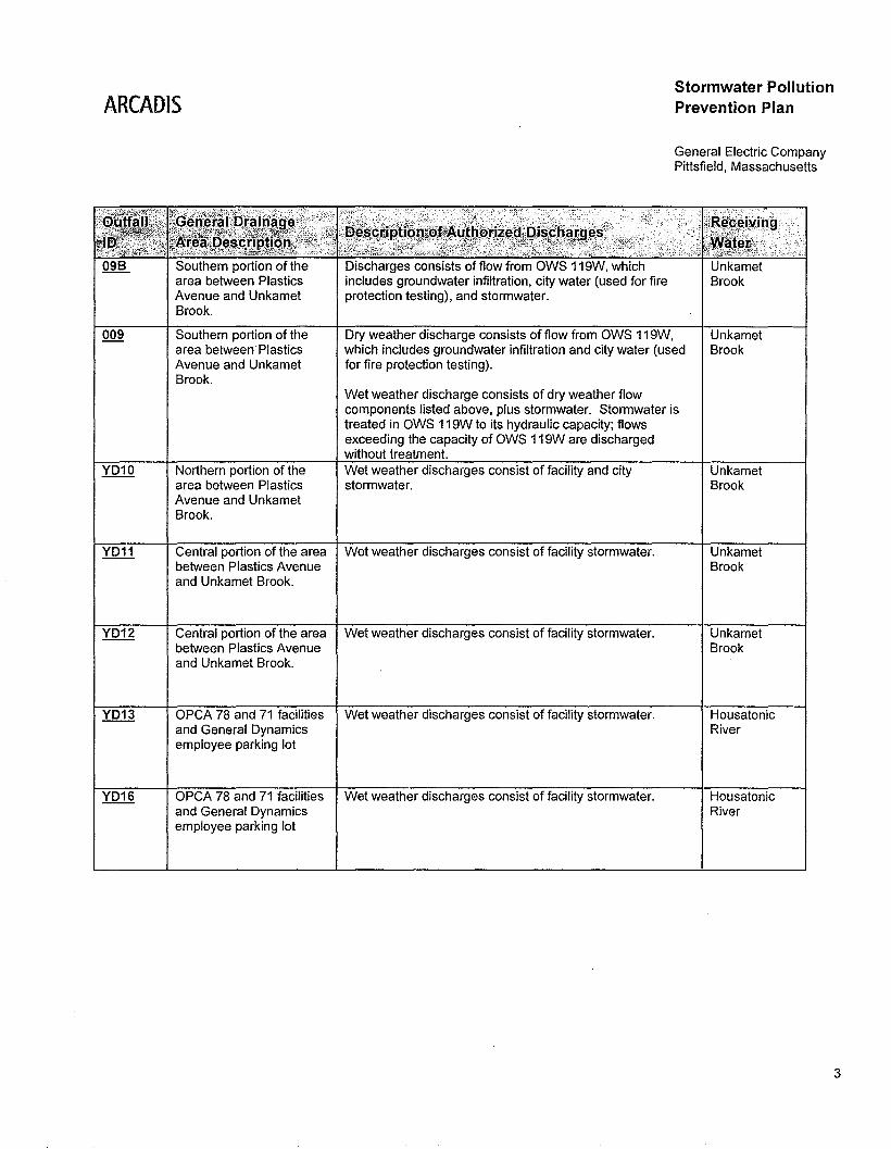
Southern portion of the Discharges consists of flow from OWS 119W, whicharea between Plastics includes groundwater infiltration, city water (used for fireAvenue and Unkamet protection testing), and stormwater.Brook.
009 Southern portion of the Dry weather discharge consists of flow from OWS 119W, Unkametarea between· Plastics which includes groundwater infiltration and city water (used BrookAvenue and Unkamet for fire protection testing).Brook.
Wet weather discharge consists of dry weather flowcomponents listed above, plus stormwater. Stormwater istreated in OWS 119W to its hydraulic capacity; flowsexceeding the capacity of OWS 119W are dischargedwithout treatment.
YD10 Northern portion of the Wet weather discharges consist of facility and city Unkametarea between Plastics stormwater. BrookAvenue and UnkametBrook.
YD11 Central portion of the area Wet weather discharges consist of facility stormwater. Unkametbetween Plastics Avenue Brookand Unkamet Brook.
YD12 Central portion of the area Wet weather discharges consist of facility stormwater. Unkametbetween Plastics Avenue Brookand Unkamet Brook.
YD13 OPCA 78 and 71 facilities Wet weather discharges consist of facility stormwater. Housatonicand General Dynamics Riveremployee parking lot
YD16 OPCA 78 and 71 facilities Wet weather discharges consist of facility stormwater. Housatonicand General Dynamics Riveremployee parking lot
3
ARCADIS
1.2 Plan Organization
This SWPPP is organized into the following sections:
Stormwater PollutionPrevention Plan
General Electric CompanyPittsfield, Massachusetts
I
\
• Section 1. Introduction - provides background, organization of this document, and
facility information; lists members and describes the activities of the Stormwater
Pollution Prevention Team (PPT).
• Section 2. Potential Pollutant Sources - presents an inventory of the potential
pollutant sources. The inventory is divided into the individual drainage areas
contributing stormwater runoff to point sources authorized by the NPDES Permit.
• Section 3. Stormwater Control Measures - presents the pollution prevention
system components and control measures that are used to meet the limitations and
conditions applicable to stormwater discharges in the NPDES Permit.
• Section 4. Schedules and Procedures for Monitoring - describes quantitative
monitoring requirements, as well as sampling procedures and associated protocol.
• Section 5. Inspections - presents the procedures for conducting and reporting
routine inspections and the annual comprehensive site inspection.
• Section 6. SWPPP Certifications - contains the following certifications: Facility
Management Certification and the Site Compliance Evaluation Certification.
• Section 7. SWPPP Modifications - describes the protocol for amending the
SWPPP, corrective actions, and corrective action reporting.
1.3 Facility Information
The GE Pittsfield, Massachusetts facility (site) is located on the eastern side of Pittsfield,
in an area that consists primarily of industrial and commercial facilities. A General Site
Location Map showing the surrounding area is provided on Figure 1 (attached), while
more detailed site maps are provided in Appendix B.
4
ARCADIS
1.3.1 Site Operations and Buildings
Stormwater PollutionPrevention Plan
General Electric CompanyPittsfield, Massachusetts
Currently, control of the site is functionally divided primarily into two groups: (1) GE
Corporate Environmental Programs (GE-CEP), and (2) GE Corporate Properties &
Services Operations (GE-CP&SO). Portions of the site are leased by GE to SABIC
Innovative Plastics (SABIC), General Dynamics, and Maxim. SABIC has processing
evaluation and development operations and offices on site. General Dynamics has US
Defense Department related operations at the site and Maxim owns and operates a
power generation facility connected to the electrical grid.
GE-CEP Site Area
GE-CEP has functional control over BUilding 59, 52 and 53 and all buildings within the
western portion of the site excluding Building 100. Many of the buildings located within
the GE-CEP area are vacant. Currently, groundwater remediation activities are conducted
in the areas south of East Street and the Building 51/59 area to address environmental
impacts from past operations at the site. GE-CEP also conducts remedial activities under
the Consent Decree throughout the site. A workday for GE-CEP-related operations
consists of a single shift, 5 days per week. However, the water (Building 64T) and
groundwater (Building 64G) treatment facilities are operated 24 hours per day, 7 days per
week. There are currently no manufacturing activities at the site.
GE-CP&SO Site Area
GE-CP&SO leases Building 100 and the eastern portion of the site east of Plastics
Avenue, excluding Building 59, 52 and 53 to SABIC. The majority of Building 100 is
operated by SABIC, which is used for research and development (R&D) of injection
molded plastic products and as storage for plastic products. Operations within GE
CP&SO and SABIC areas are typically conducted in one shift, 5 days per week. There
are currently no manufacturing activities at the GE-CP&SO/SABIC site.
GE Global Research Center (GE-GRC) will operate within the western end of Building
100 following construction of a new deep sea pump test facility. Operations within the
GE-GRC areas are expected to be conducted in one shift, 5 days per week. There are no
manufacturing activities expected at the GE-GRC location.
5
ARCADISStormwater PollutionPrevention Plan
General Electric CompanyPittsfield, Massachusetts
In addition, the area of the site east of Woodlawn Avenue, north of East Street, and south
of the railroad tracks that run along Merrill Road is owned by the Pittsfield Economic
Development Authority (PEDA). That area was previously owned by GE and was
conveyed to PEDA in 2005.
1.3.2 Site Access
Access to the GE site is limited by use of employee/contractor access badges. Visitors
must check in with plant security before entering the site. GE-CEP contract workers must
check in with a GE employee or representative and attend mandatory safety training prior
to conducting business at the site. Within the GE-CP&SO, GE-GRC, and SABIC areas,
contractors are required to check in at Gate 130 or the Building 100 reception desk to be
issued a contractor access badge or a day pass and to ensure they have participated in
the mandatory safety training. Contract workers receive training about potential hazards
they may be exposed to while working at the site, as well as instruction on evacuation
procedures. All plant areas are designed for adequate movement of emergency
personnel and equipment.
1.3.3 Storm Sewer Mapping
Stormwater runoff, which is discharged from the NPDES authorized outfalls, is collected
and conveyed via a series of manholes, catch basins, and piping. In accordance with
Part I.C.2.a of the NPDES Permit, GE updated the site's storm sewer mapping in 2009 for
this SWPPP. All manholes and catch basins that are hydraulically connected to the
authorized outfalls were inspected to determine pipe type, pipe sizes, connections, and
approximate locations of structures. The updated storm sewer mapping is presented in
Appendix B.
1.4 Stormwater Pollution Prevention Team (PPT)
The individuals who comprise the PPT were selected based on their familiarity with
pollution control and pollution prevention, as well as their day-to-day functional
responsibility and responsibility regarding other environmental management plans in use
at the site. Members of the PPT are familiar with spill prevention, spill containment,
emergency response, and pollution prevention best management practices (BMPs) and
are identified below. These individuals are responsible for defining stormwater pollution
6
ARCADISStormwater PollutionPrevention Plan
General Electric CompanyPittsfield, Massachusetts
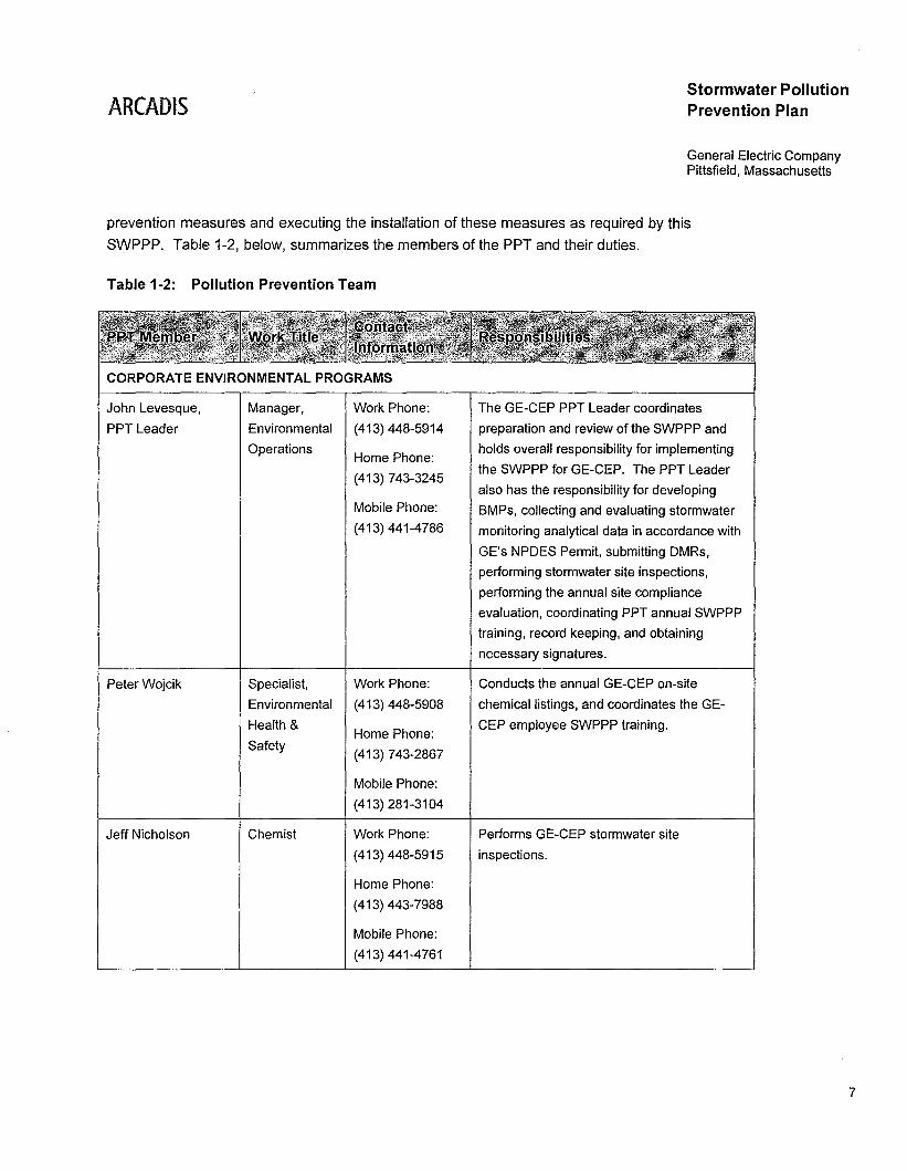
prevention measures and executing the installation of these measures as required by this
SWPPP. Table 1-2, below, summarizes the members of the PPT and their duties.
Table 1-2: Pollution Prevention Team
CORPORATE ENVIRONMENTAL PROGRAMS
John Levesque,
PPT Leader
Manager,
Environmental
Operations
Work Phone:
(413) 448-5914
Home Phone:
(413) 743-3245
Mobile Phone:
(413) 441-4786
The GE-CEP PPT Leader coordinates
preparation and review of the SWPPP and
holds overall responsibility for implementing
the SWPPP for GE-CEP. The PPT Leader
also has the responsibility for developing
BMPs, collecting and evaluating stormwater
monitoring analytical data in accordance with
GE's NPDES Permit, submitting DMRs,
performing stormwater site inspections,
performing the annual site compliance
evaluation, coordinating PPT annual SWPPP
training, record keeping, and obtaining
necessary signatures.
Peter Wojcik Specialist, Work Phone:
Environmental (413) 448-5908
Health &Home Phone:
Safety(413) 743-2867
Mobile Phone:
(413) 281-3104
Jeff Nicholson Chemist Work Phone:
(413) 448-5915
Home Phone:
(413) 443-7988
Mobile Phone:
(413) 441-4761
Conducts the annual GE-CEP on-site
chemical listings, and coordinates the GE
CEP employee SWPPP training.
Performs GE-CEP stormwater site
inspections.
7
ARCADISStormwater PollutionPrevention Plan
General Electric CompanyPittsfield, Massachusetts
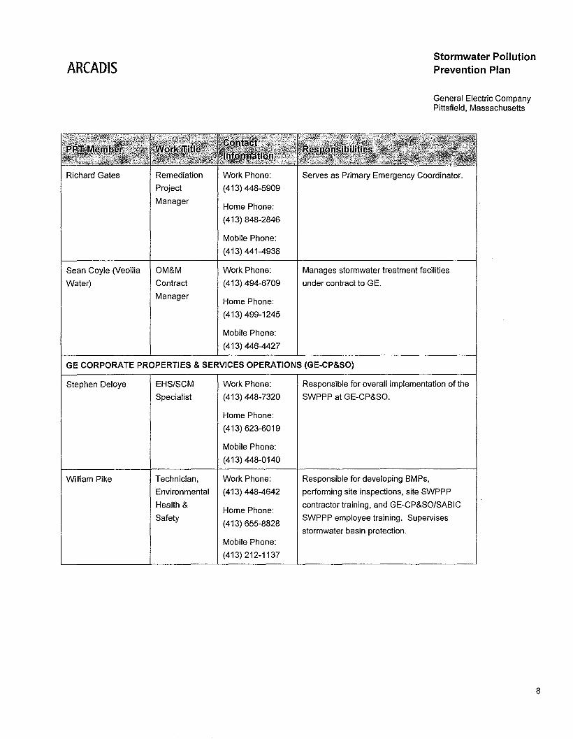
Richard Gates
Sean Coyle (Veoilia
Water)
Remediation
Project
Manager
OM&M
Contract
Manager
Work Phone:
(413) 448-5909
Home Phone:
(413) 848-2846
Mobile Phone:
(413) 441-4938
Work Phone:
(413) 494-6709
Home Phone:
(413) 499-1245
Mobile Phone:
(413) 446-4427
Serves as Primary Emergency Coordinator.
Manages stormwater treatment facilities
under contract to GE.
GE CORPORATE PROPERTIES & SERVICES OPERATIONS (GE-CP&SO)
Stephen Deloye
William Pike
EHS/SCM
Specialist
Technician,
Environmental
Health &
Safety
Work Phone:
(413) 448-7320
Home Phone:
(413) 623-6019
Mobile Phone:
(413) 448-0140
Work Phone:
(413) 448-4642
Home Phone:
(413) 655-8828
Mobile Phone:
(413) 212-1137
Responsible for overall implementation of the
SWPPP at GE-CP&SO.
Responsible for developing BMPs,
performing site inspections, site SWPPP
contractor training, and GE-CP&SO/SABIC
SWPPP employee training. Supervises
stormwater basin protection.
8
AHeADIS
1.4.1 Emergency Coordinators
Stormwater PollutionPrevention Plan
General Electric CompanyPittsfield, Massachusetts
The PPT also consists of Emergency Coordinators, in the event of a chemical release or
incident at the site, as follows:
• Mr. Richard Gates, primary Emergency Coordinator; for the GE-CEP portion of the
site;
• Mr. John J. Levesque, alternate Emergency Coordinator for the GE-CEP portion of
the site;
• Mr. Stephen Deloye, primary Emergency Coordinator for GE Corporate Properties &
Services Operations; and
• Mr. William Pike, 'alternate Emergency Coordinator for GE Corporate Properties &
Services Operations.
In addition to the Emergency Coordinators named above, ARCADIS and VeoliaEnvironmental Services provide emergency response assistance for releases/incidents.The Emergency Coordinators and support personnel have all received at least 8 hours ofhazardous waste management training.
GE also maintains a Spill Prevention, Control and Countermeasure (SPCC) Plan, a
Hazardous Waste Facility Contingency Plan, and a Project Operations Plan (POP).
These plans identify specific ,individuals who are responsible for implementing the
activities outlined in the plans. The PPT leader is responsible for maintaining consistency
among the SWPPP and these plans. Copies of these plans will be kept on site with this
SWPPP at all times.
9
ARCADIS
2. Potential Pollutant Sources
Stormwater PollutionPrevention Plan
General Electric CompanyPittsfield. Massachusetts
The following section presents a brief overview of each drainage area associated with the
authorized outfalls included in the NPDES Permit. In addition. in accordance with the
requirements of Part I.C (and the MSGP conditions incorporated by reference therein).
this section includes a summary of potential pollutant sources and a description of non
stormwater discharges.
2.1 Drainage Area Descriptions
2.1.1 Drainage Area 005
This drainage basin encompasses most of the western portion of the area south of East
Street and some portions north of East Street. This drainage area includes Buildings 64,
64S, 65, and OillWater Separator (OWS) 64W and 64Z located south of East Street. This
drainage area also includes Buildings 7, 12, 12T. 12X, 12Y, 14, 100, 100A, and 100B
located north of East Street. The Pittsfield Economic Development Authority (PEDA)
property east of Woodlawn Avenue, north of East Street, and south of the railroad tracks
that run along Merrill Road generates stormwater that is conveyed to this drainage area.
Additionally, City of Pittsfield property, including Tyler Street, areas extending to the north,
and portions of East Street discharge stormwater that is conveyed to this drainage area.
Runoff from drainage area 005 is collected and conveyed through an intricate series of
manholes, catch basins, and treatment systems prior to discharge to the Housatonic
River. Refer to Section 3.2 of this SWPPP and the site Stormwater Management Plan
(BBL, 2000) for additional information pertaining to stormwater management in this
drainage area.
2.1.2 Drainage Area 006
This drainage basin encompasses most of the eastern portion of the area south of East
Street, directly west of Newell Street, and also includes portions north of East Street.
This drainage area includes the baseball field west of Newell Street, OWS 64X, and the
grassed area to the east of 64V, 64R, and 64G Groundwater Treatment Plant (GWTP)
located south of East Street. Areas north of East Street include the area south of Merrill
Road and east of Building 69. In addition, stormwater runoff from portions of the area
west of Newell Street. East Street, and Merrill Road is conveyed to this drainage area.
10
ARCADISStormwater PollutionPrevention Plan
General Electric CompanyPittsfield, Massachusetts
Runoff from drainage area 006 is collected via a series of manholes and catch basins and
conveyed to OWS 64X for treatment, prior to discharge to the Housatonic River. Refer to
Section 3.2 of this SWPPP and the site Stormwater Management Plan (BBL, 2000) for
additional information pertaining to stormwater management in this drainage area.
2.1.3 Drainage Area 009
This drainage area encompasses the area east of Plastics Avenue and north of Merrill
Road. This area includes Buildings 51, 52, 53, 59, and 119 and areas to the north of
OWS 119W.
Runoff from drainage area 009 is collected via a series of manholes and catch basins and
conveyed to OWS 119W for treatment, prior to discharge to the Unkamet Brook. Refer to
Section 3.2 of this SWPPP and the site Stormwater Management Plan (BBL, 2000) for
additional information pertaining to stormwater management in this drainage area.
2.1.4 Drainage Area YD10
Features located within Drainage Area YD10 include the High Bay Building 130, the
stormwater detention pond adjacent to Dalton Avenue, and the residential neighborhood
bounded by Dalton Avenue, Allendale Road, Maryland Avenue, and Plastics Avenue. A
portion of the High Bay Building 130 was formerly used for research and development.
Runoff from YD10 drains to Unkamet Brook via a series of manholes, catch basins, and
through a stormwater detention pond.
2.1.5 Drainage Area YD11
This drainage area includes portions of the High Bay Building 130, the GE-CP&SO office
building, Building 105, Building 105 Courtyard, half of Building 106, and Building 121, as
well as a portion of the GE-CP&SO parking lot.
Runoff from Drainage Area YD11 drains via a series of manholes and catch basins to
Unkamet Brook.
11
ARCADIS
2.1.6 Drainage Area YD12
Stormwater PollutionPrevention Plan
General Electric CompanyPittsfield, Massachusetts
This drainage area includes Buildings 51A, 105X, 116, 118, 121, and 125, as well as the
main thoroughfare through the GE-CP&SO from Gate 51 to BUilding 120X.
Runoff from Drainage Area YD12 drains via a series of manholes and catch basins to
Unkamet Brook.
2.1.7 Drainage Area YD13
This drainage area includes a portion of the lined and capped On-Plant Consolidation
Area (OPCA) facility, referred to as OPCA 71, and the currently open OPCA 78, portions
of the General Dynamics employee parking lots north and west of the OPCA facility, and
adjacent areas.
Stormwater runoff from the OPCA 71 and 78 facilities enters the Pittsfield Generating
Company storm drain system via the stormwater collection basin. Runoff from the
General Dynamics parking area enters the Pittsfield Generating Company storm drain
system at the manhole downstream of the OPCA 71 Cell stormwater collection basin.
These stormwater flows ultimately discharge into a small stream that leads to the
Housatonic River.
2.1.8 Drainage Area YD16
This drainage area includes portions of the General Dynamics employee parking lot east
of Yard Drain YD16 and a portion of the lined and capped OPCA 71 and the currently
open OPCA 78 facility. Stormwater runoff from the General Dynamics parking lot and a
portion of OPCA 71 and 78 enters the storm drain via the stormwater collection basin,
which then flows into the YD16 outlet manhole. Stormwater collected in the outlet
manhole flows approximately 400 feet through a 12-inch diameter pipe entering a
stormwater structure where it then combines with City of Pittsfield stormwater. The
combined stormwater ultimately discharges into the Housatonic River.
12
ARCADIS
2.2 Identification of Pollutants and Potential Pollutant Sources
Stormwater PollutionPrevention Plan
General Electric CompanyPittsfield, Massachusetts
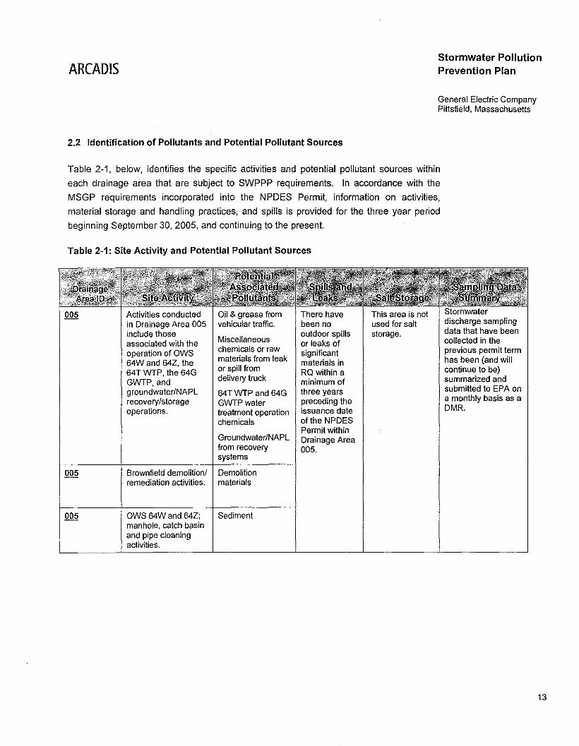
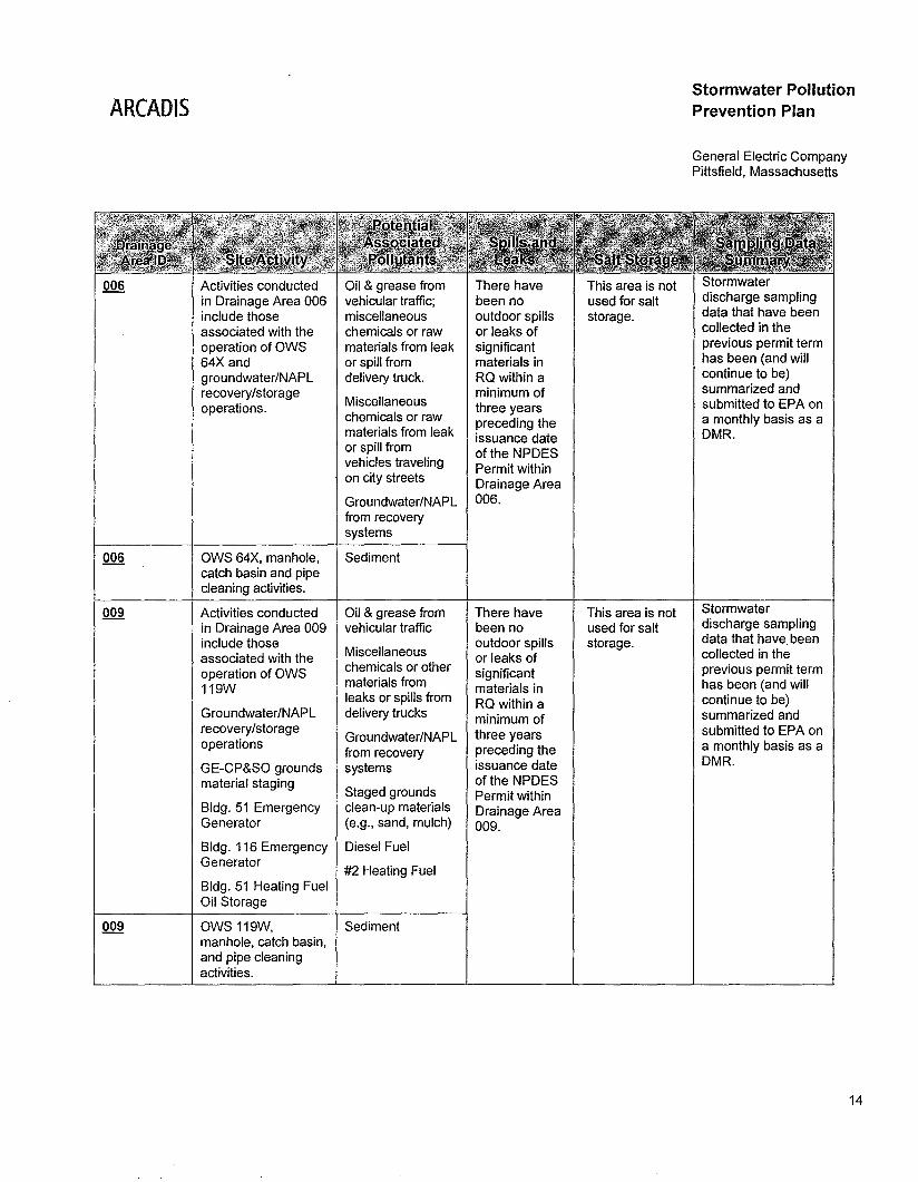
Table 2-1, below, identifies the specific activities and potential pollutant sources within
each drainage area that are subject to SWPPP requirements. In accordance with the
MSGP requirements incorporated into the NPDES Permit, information on activities,
material storage and handling practices, and spills is provided for the three year period
beginning September 30, 2005, and continuing to the present.
Table 2-1: Site Activity and Potential Pollutant Sources
005 Activities conducted Oil & grease from There have This area is not Stormwater
in Drainage Area 005 vehicular traffic. been no used for salt discharge sampling
include those outdoor spills storage. data that have been
associated with the Miscellaneous or leaks of collected in the
operation of OWS chemicals or raw significant previous permit term
64W and 64Z, the materials from leak materials in has been (and will
64T WTP, the 64G or spill from RQ within a continue to be)
GWTP,and delivery truck minimum of summarized and
groundwater/NAPL 64T WTP and 64G three years submitted to EPA on
recovery/storage GWTPwater preceding the a monthly basis as a
operations. treatment operation issuance date DMR.
chemicals of the NPDESPermit within
Groundwater/NAPL Drainage Areafrom recovery 005.systems
005 Brownfield demolition/ Demolitionremediation activities. materials
005 OWS 64W and 64Z; Sedimentmanhole, catch basinand pipe cleaningactivities.
13
AHeADISStormwater PollutionPrevention Plan
General Electric CompanyPittsfield, Massachusetts
006 Activities conducted Oil & grease from There have This area is not Stormwater
in Drainage Area 006 vehicular traffic; been no used for salt discharge sampling
include those miscellaneous outdoor spills storage. data that have been
associated with the chemicals or raw or leaks of collected in the
operation of OWS materials from leak significant previous permit term
64X and or spill from materials in has been (and will
groundwater/NAPL delivery truck. RQ within a continue to be)
recovery/storage minimum of summarized and
operations. Miscellaneous three years submitted to EPA onchemicals or raw preceding the a monthly basis as amaterials from leak issuance date DMR.or spill from of the NPDESvehicles traveling Permit withinon city streets Drainage AreaGroundwater/NAPL 006.from recoverysystems
006 OWS 64X, manhole, Sedimentcatch basin and pipecleaning activities.
009 Activities conducted Oil & grease from There have This area is not Stormwater
in Drainage Area 009 vehicular traffic been no used for salt discharge sampling
include those outdoor spills storage. data that have been
associated with the Miscellaneous or leaks of collected in the
operation of OWS chemicals or other significant previous permit term
119W materials from materials in has been (and willleaks or spills from RQ within a continue to be)
Groundwater/NAPL delivery trucks minimum of summarized andrecovery/storage
Groundwater/NAPL three years submitted to EPA onoperations
from recovery preceding the a monthly basis as a
GE-CP&SO grounds systems issuance date DMR.
material staging of the NPDESStaged grounds Permit within
Bldg. 51 Emergency clean-up materials Drainage AreaGenerator (e.g., sand, mulch) 009.
Bldg. 116 Emergency Diesel FuelGenerator
#2 Heating FuelBldg. 51 Heating FuelOil Storage
009 OWS 119W, Sedimentmanhole, catch basin,and pipe cleaningactivities.
14
ARCADISStormwater PollutionPrevention Plan
General Electric CompanyPittsfield, Massachusetts
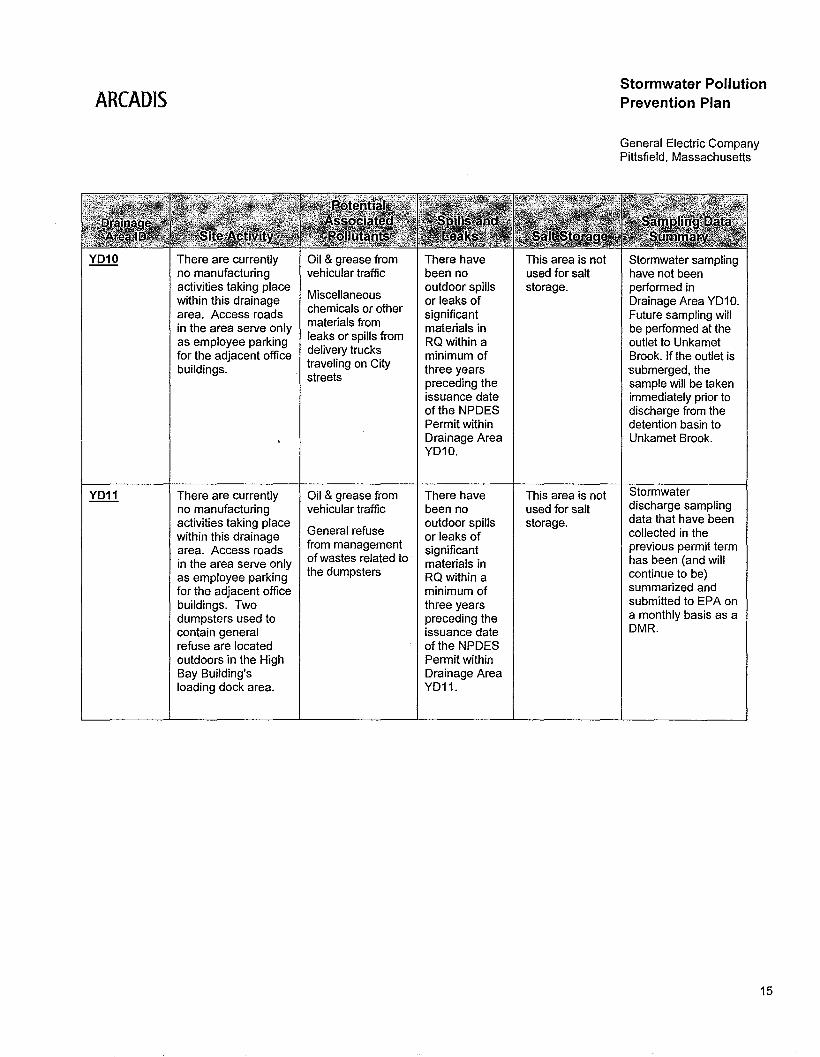
YD10 There are currently Oil & grease from There have This area is not Stormwater samplingno manufacturing vehicular traffic been no used for salt have not beenactivities taking place
Miscellaneousoutdoor spills storage. performed in
within this drainagechemicals or other
or leaks of Drainage Area YD10.area. Access roads
materials fromsignificant Future sampling will
in the area serve onlyleaks or spills from
materials in be performed at theas employee parking RQ within a outlet to Unkametfor the adjacent office delivery trucks minimum of Brook. If the outlet isbuildings. traveling on City three years submerged, the
streets preceding the sample will be takenissuance date immediately prior toof the NPDES discharge from thePermit within detention basin toDrainage Area Unkamet Brook.YD10.
YD11 There are currently Oil & grease from There have This area is not Stormwater
no manufacturing vehicular traffic been no used for salt discharge sampling
activities taking place outdoor spills storage. data that have been
within this drainage General refuse or leaks of collected in the
area. Access roads from management significant previous permit term
in the area serve only of wastes related to materials in has been (and will
as employee parking the dumpsters RQ within a continue to be)
for the adjacent office minimum of summarized and
buildings. Two three years submitted to EPA on
dumpsters used to preceding the a monthly basis as a
contain general issuance date DMR.
refuse are located of the NPDESoutdoors in the High Permit withinBay Building's Drainage Arealoading dock area. YD11.
15
ARCADISStormwater PollutionPrevention Plan
General Electric CompanyPittsfield, Massachusetts
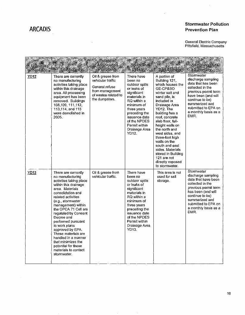
YD12 There are currently Oil & grease from There have A portion of Stormwater
no manufacturing vehicular traffic been no Building 121, discharge sampling
activities taking placeGeneral refuse
outdoor spills which houses the data that has been
within this drainage or leaks of GE-CP&SO collected in the
area. All processing from management significant winter salt and previous permit term
equipment has been of wastes related to materials in sand pile, is have been (and will
removed. Buildings the dumpsters. RQ within a included in continue to be)
108,109,111,112, minimum of Drainage Area summarized and
113,114, and 115 three years YD12. The submitted to EPA on
were demolished in preceding the building has a a monthly basis as a
2005. issuance date roof, concrete DMR.
of the NPDES slab floor, full-Permit within height walls onDrainage Area the north andYD12. west sides, and
three-foot highwalls on thesouth and eastsides. Materialsstored in Building121 are notdirectly exposedto stormwater.
YD13 There are currently Oil & grease from There have This area is not Stormwater
no manufacturing vehicular traffic. been no used for salt discharge sampling
activities taking place outdoor spills storage. data that have been
within this drainage or leaks of collected in the
area. Materials significant previous permit term
consolidation and materials in has been (and will
related activities RQ within a continue to be)
(e.g., stormwater minimum of summarized and
management) within three years submitted to EPA on
the OPCA 71 Cell are preceding the a monthly basis as a
regulated by Consent issuance date DMR.
Decree and of the NPDESperformed pursuant Permit withinto work plans Drainage Areaapproved by EPA. YD13.These materials arehandled in a mannerthat minimizes thepotential for thesematerials to contactstormwater.
16
AHeADIS
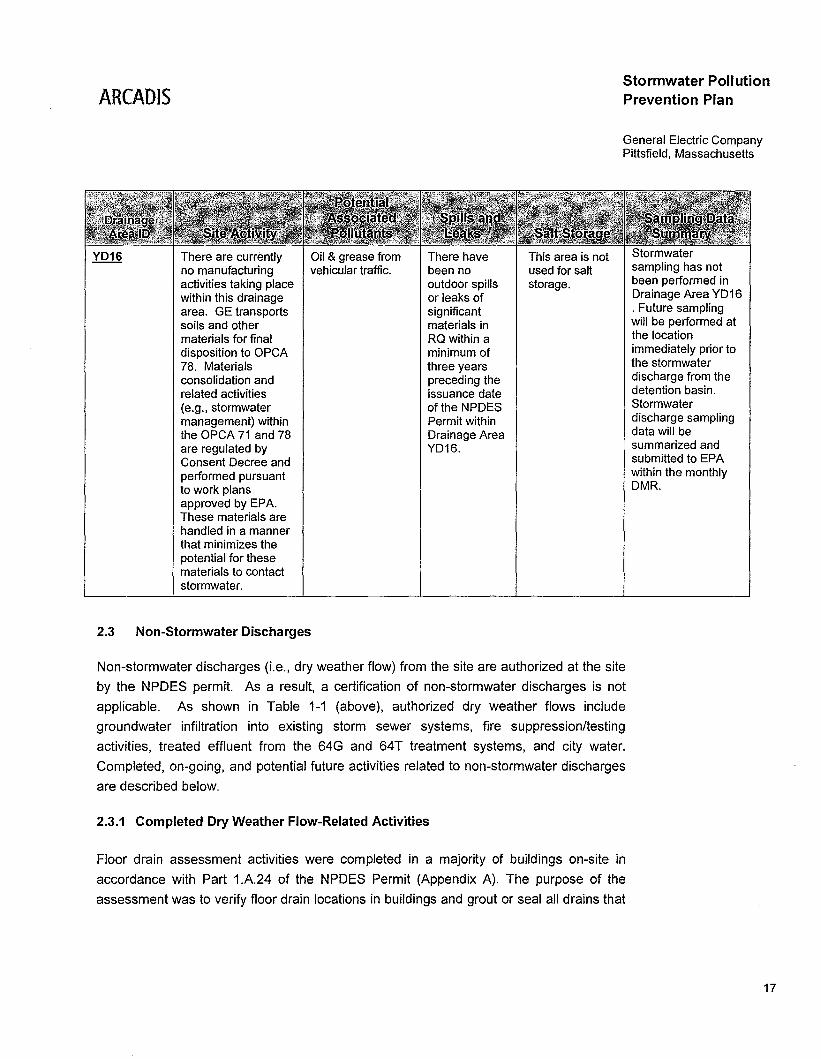
There are currentlyno manufacturingactivities taking placewithin this drainagearea. GE transportssoils and othermaterials for finaldisposition to OPCA78. Materialsconsolidation andrelated activities(e.g., stormwatermanagement) withinthe OPCA 71 and 78are regulated byConsent Decree andperformed pursuantto work plansapproved by EPA.These materials arehandled in a mannerthat minimizes thepotential for thesematerials to contactstormwater.
Oil & grease fromvehicular traffic.
There havebeen nooutdoor spillsor leaks ofsignificantmaterials inRQ within aminimum ofthree yearspreceding theissuance dateof the NPDESPermit withinDrainage AreaYD16.
This area is notused for saltstorage.
Stormwater PollutionPrevention Plan
General Electric CompanyPittsfield, Massachusetts
Stormwatersampling has notbeen performed inDrainage Area YD16. Future samplingwill be performed atthe locationimmediately prior tothe stormwaterdischarge from thedetention basin.Stormwaterdischarge samplingdata will besummarized andsubmitted to EPAwithin the monthlyDMR.
2.3 Non-Stormwater Discharges
Non-stormwater discharges (Le., dry weather flow) from the site are authorized at the site
by the NPDES permit. As a result, a certification of non-stormwater discharges is not
applicable. As shown in Table 1-1 (above), authorized dry weather flows include
groundwater infiltration into existing storm sewer systems, fire suppression/testing
activities, treated effluent from the 64G and 64T treatment systems, and city water.
Completed, on-going, and potential future activities related to non-stormwater discharges
are described below.
2.3.1 Completed Dry Weather Flow-Related Activities
Floor drain assessment activities were completed in a majority of buildings on-site in
accordance with Part 1.A.24 of the NPDES Permit (Appendix A). The purpose of the
assessment was to verify floor drain locations in buildings and grout or seal all drains that
17
ARCADISStormwater PollutionPrevention Plan
General Electric CompanyPittsfield, Massachusetts
were connected to a storm sewer system. As a result of subsequent closure activities, a
total of 110 drains were permanently sealed with grout and inspected to confirm
abandonment. Floor drain closures took place in JUly and August 2006 and from March
through June 2009.
2.3.2 On-going Dry Weather Flow-Related Activities
In accordance with Part 1.A.13 of the NPDES Permit, GE is currently monitoring YD10.
YD11, YD12. YD13. and YD16 for the presence of dry weather flow. The monitoring will
be conducted for a period of one year from the effective date of the NPDES Permit
(January 1. 2009). The results of monitoring have been summarized and included in the
monthly DMR.
2.3.3 Potential Future Dry Weather Flow-Related Activities
Pending final issuance of a major modification to the NPDES Permit (see footnote 1
above). GE will develop and implement a dry weather flow elimination program. This
program will include evaluations to determine the occurrences of dry weather flows from
outfalls 05A, 64T, 006, and 009 and identify the sources of such flow. In addition,
controls will be implemented to reduce and/or eliminate dry weather flow from these
outfalls. The schedule for completion for the dry weather flow elimination program is
approximately 42 months from the effective date of the NPDES Permit Modification, with
interim milestones for SUbstantially completing an initial round of flow reduction measures
within 17 months and substantially completing any necessary follow-on rounds of flow
reduction measures within 29 months.
18
AHeADIS
3. Stormwater Control Measures
Stormwater PollutionPrevention Plan
General Electric CompanyPittsfield, Massachusetts
This section presents the stormwater control measures that GE uses or will use to: (1)
reduce the potential for pollutants in the site's stormwater discharges; and (2) ensure
compliance with applicable requirements of the NPDES Permit, including MSGP
provisions incorporated therein.
As such, this section presents the controls that have been selected to meet non-numeric
technology based effluent limits for the pollution sources identified in all drainage areas.
This section also describes the management of stormwater runoff that will be
accomplished using existing stormwater treatment facilities/controls at the site.
3.1 Non-Numeric Technology-Based Controls
Non-numeric technology-based controls (Le., BMPs) have been selected to meet applicablerequirements of the NPDES Permit in all drainage areas. As described below, thesecontrols include good housekeeping, employee training, facility security, preventivemaintenance, spill prevention and response, management of stormwater runoff, sedimentand erosion control, record keeping, and incident reporting.
3.1.1 Good Housekeeping
When used in conjunction with routine inspections (see Section 5.1.1), good
housekeeping can be a very effective method of pollution prevention. The MSGP requires
that facilities limit the amount of spilled, settled, and leaked materials that can be washed
away with stormwater. The following are examples of good housekeeping practices:
• Scheduling regular pickup and disposal of garbage and waste materials;
• Routinely inspecting for leaks and observing conditions of drums, tanks, and
containers;
• Promptly performing cleanup of spilled materials;
• Ensuring that cleanup procedures are reviewed and understood by employees;
19
ARCADISStormwater PollutionPrevention Plan
General Electric CompanyPittsfield, Massachusetts
• Keeping an up-to-date inventory of all materials present at the site and clearly
labeling containers; and
• Maintaining clean ground surfaces with regular sweeping, vacuuming, etc.
GE will implement all of the above housekeeping practices within all drainage areas.
Refuse removal and disposal is performed by solid waste contractors. Areas around the
waste collection vessels are inspected in accordance with Section 5.1.1. These
inspections also include all significant material storage and handling areas, and are
designed to uncover leak or spill conditions that could potentially impact stormwater
runoff. Spills are cleaned-up in accordance with Section 3.1.5 of this SWPPP.
In paved and other impervious areas, sweeping is performed periodically to reduce
pollutants in stormwater discharges. Sweeping frequency is determined based on the
rates of accumulation of particular materials and their potential impact on stormwater
discharges. In 2005, GE purchased an industrial vac-sweeper to further reduce pollutants
by increasing the frequency of the periodic cleaning of impervious surfaces.
Cleaning and inspection of manholes/catch basins and OWS 64W, 64X, 64Z, and 119W
are conducted in accordance with the Attachment C of the NPDES Permit. As indicated in
Attachment C to the NPDES Permit, all manholes and catch basins on GE property will be
initially inspected and cleaned within Drainage Basins 005, 006, and 009. Select manholes
and catch basins will be inspected on a quarterly basis to evaluate the need for subsequent
removal activities. The removal of sediment and other debris from the selected manholes
and catch basins will be performed as needed (Le., when observed debris thickness
exceeds approximately 6 inches and prior to the catch basin exceeding 50% of its sediment
storage capacity). In addition, OWS 64W, 64X, 64Z, and 119W will be cleaned and
subsequently inspected for re-accumulation of sediments/debris. Cleaning of accumulated
sediments/debris from OWS units will be performed every 2 years or sooner if average
thickness of debris observed during annual inspections exceeds 6 inches.
3.1.2 Employee Training
As with all of GE's Environmental, Health, and Safety programs, well-trained GE
employees play a critical role in achieving the objectives of this SWPPP. Therefore,
operations managers, PPT members, contractors, and others identified by the PPT,
20
ARCADISStormwater PollutionPrevention Plan
General Electric CompanyPittsfield, Massachusetts
working where significant materials are handled will be given instruction and information
regarding:
• Environmental laws and regulations;
• Pollution prevention concepts;
• Content of this SWPPP;
• Measures and controls to be used in each drainage area to minimize the pollutants in
facility stormwater discharges; and
• Site spill/release emergency response procedures.
Employee training also covers procedures for cleaning and washing equipment and
containers. The training emphasizes the potential human hazards and environmental
impacts from the discharge of residual wash water.
After the initial training, refresher training sessions will be held at least once per year
following the completion of the Site Compliance Evaluation and SWPPP revisions, or
more frequently when appropriate. Employee training records will be included in Appendix
C as training is completed.
3.1.3 Site Security
Access to the site is restricted by fencing and electronically controlled gates that are
monitored from security stations by closed-circuit television. All contractors and persons
on extended visits are issued badges for access to the site. All contractors and persons
on extended visits to the GE-CEP facilities are pre-approved by GE prior to entry.
Infrequent visitors must register at the reception desk and are escorted to their on-site
destination by GE personnel. No additional security measures are warranted to prevent
accidental or intentional entry to the site that could cause an unauthorized discharge of
pollutants to waters of the United States.
21
ARCADIS
3.1.4 Preventive Maintenance
Stormwater PollutionPrevention Plan
General Electric CompanyPittsfield, Massachusetts
A preventive maintenance program for outdoor equipment will be used in conjunction with
routine inspections (see Section 5.1.1). The inspections are designed to reveal
conditions that could cause breakdowns or failures that may result in the discharge of
pollutants. In addition, routine maintenance is conducted on the stormwater management
controls located at the site (e.g., oil/water separators, 64T WTP, 64G GWTP). Copies of
completed maintenance reports are kept at the site.
3.1.5 Spill Prevention and Response Procedures
In the event of a spill, trained site personnel will perform specific response procedures as
are outlined in the GE Integrated Emergency Response Plan (Project Operation Plan
[POP], Exhibit F-1). All personnel designated to engage in emergency spill response are
fUlly trained and -properly equipped. VeoHa Environmental Services and ARCADIS are
also available to respond to major chemical releases and incidents at the site in support
of GE personnel.
All spills, releases, inspection results and maintenance issues related to stormwater are
to be immediately brought to the attention of the manager listed in the GE Integrated
Emergency Response Plan.
In cases where a permitted stormwater discharge contains a hazardous substance or oil
in an amount equal to or in excess of a RQ or standard, the incident reporting procedures
outlined in Section 3.1.6 below and the POP (Attachment F - Contingency and
Emergency Response Plan) will be followed. A complete list of spill response procedures
is located in the GE Integrated Emergency Response Plan.
To minimize the potential for leaks, spills, and other releases that may be exposed to
stormwater, the following preventative measures will be carried out to the extent
practicable:
• Plainly labeling containers (e.g., "Universal Waste," "Hazardous Waste," etc.), which
could be susceptible to spillage and/or leakage, to encourage the proper handling of
the container and material and to facilitate a rapid response if spills or leaks occur;
• Installing barriers between material storage and traffic areas;
22

ARCADIS
• Providing secondary containment around material storage areas; and
Stormwater PollutionPrevention Plan
General Electric CompanyPittsfield, Massachusetts
• Reviewing and posting signage related to material storage and handling areas in
plain sight.
3.1.6 Incident Reporting
All spills, releases, inspection results and maintenance issues related to stormwater
pollution prevention are to be immediately brought to the attention of the PPT Leaders.
In cases where a stormwater discharge that is authorized by the NPDES Permit contains
a hazardous substance or oil in an amount equal to or in excess of an Reportable
Quantities (RQ) or standard established under 40 CFR 110, 40 CFR 117, 40 CFR 302 or
310 CMR 40, etc. the following actions will be taken:
• The person in charge of the site is required to notify the National Response Center
(NRC) [800-424-8802] in accordance with the requirements of 40 CFR 110, 40 CFR
117 and 40 CFR 302 as soon as they have knowledge of the discharge exceeding
the RQ;
• The SWPPP for the site must be amended within 14 calendar days of knowledge of
the release to provide description of the release, an account of the circumstances
leading to the release and the date of the release. In addition, the plan must be
reviewed to identify measures to prevent the reoccurrence of such releases and
modified where appropriate; and
• The permittee must also submit to EPA within 14 calendar days of knowledge of the
release a written description of the RQ release (including type and estimate of the
amount of material released), the date that such release occurred, the circumstances
leading to the release and steps taken to modify the pollution prevention plan.
A prohibited discharge to the waters of the United States or its adjoining shoreline is
defined to be a discharge in harmful quantities. Harmful quantity is defined at 40 CFR
110.3, to include discharges that:
23
ARCADIS
a. Violate water quality standards; or
Stormwater PollutionPrevention Plan
General Electric CompanyPittsfield, Massachusetts
b. Cause a film or sheen upon or discoloration of the surface of the water or adjoining
shorelines or cause a sludge or emulsion to be deposited beneath the surface of the
water or upon the adjoining shoreline.
3.1.7 Recordkeeping and Internal Reporting
Spill and pollution prevention efforts can be enhanced by retaining records in an orderly
manner at the site. Therefore, records regarding stormwater pollution prevention
activities will be maintained on-site for 6 years, or until 1 year after the coverage under
the NPDES Permit terminates, whichever is longer.
The records retained will include:
• NPDES Permit No. MA0003891;
• All inspection reports;
• All corrective action reports (see Section 7.1);
• All spill reports;
• All Site Compliance Evaluation reports;
• SWPPP and all revisions thereto;
• All stormwater-related maintenance reports;
• All stormwater monitoring records; and
• All signed certifications.
Please refer to Section 5 for detailed requirements concerning Annual Site Compliance
Evaluations.
All reportable spills will be recorded and documented within this SWPPP. Spills will be
noted with respect to date, time, location, volume and contents of spill. Detailed reports
including date and time of the incident, weather conditions, response procedures, parties
notified, recommended revisions to the BMP program, operating procedures, and/or
equipment needed to prevent recurrence shall be filed or their file location referenced in
24
AReADISStormwater PollutionPrevention Plan
General Electric CompanyPittsfield, Massachusetts
Appendix E. Spill Response Documentation forms are located with the GE Integrated
Emergency Response Plan.
3.1.8 Sedimentation and Erosion Control
On an ongoing basis during Brownfield demolition activities and remedial action projects,
sedimentation and erosion controls are put into effect in accordance with the project's
BMPs. These controls may include, but are not limited to, silt fence, hay bails,
manhole/catch basin blocking, and pneumatic/mechanical pipe plugs. Before starting
demolition activities, the project's stormwater system is reviewed and appropriate
protection is identified and put into place. In addition, dust control measures are used in
conjunction with air-monitoring to ensure adequate control of dust and other airborne
pollutants.
A large portion of the site consists of paved or other impervious surfaces, thus limiting the
potential for erosion. Grass and other landscaped areas are being monitored and will
continue to be monitored for signs of erosion by on-site personnel.
3.2 Stormwater Management Controls
The following describes the existing stormwater treatment facilities, by drainage area, that
manage runoff from the site. As described below, site stormwater is managed through
the use of stormwater detention basins, oil/water separators, and a dedicated stormwater
treatment facility. In addition, for drainage areas where specific structural stormwater
management controls are not present, the management practices used to minimize the
potential for the introduction of pollutants to stormwater runoff are described below.
Any floatable debris that is contained in the storm drainage flow is collected as it passes
through barrel screens and an underflow arrangement at the various oil/water separators.
OWS 64W, 64X, and 119W will be modified with an overflow weir arrangement to
facilitate settlement of sediments in the separators. An overflow weir was installed in
OWS 64Z in 2006.
The 64T WTP is a Massachusetts Industrial Class 4 Treatment Plant, designed for the
removal of sediments. The facility has a 0.5-million gallon per day design capacity and
was originally constructed in 1987.
25
ARCADIS
3.2.1 Drainage Area 005
Stormwater PollutionPrevention Plan
General Electric CompanyPittsfield, Massachusetts
Drainage Area 005 contains two oil/water separators (Le., OWS 64Z and 64W) and 64T
WTP. During dry weather conditions and initial stormwater conditions, flows generated
on the north side of East Street (including run-on to this area) are first conveyed to and
treated by OWS 64Z, then are transported for treatment at 64T WTP, and from there are
finally discharged through Outfall 005.
Under full stormwater conditions, flows generated on the north side of East Street flow
through OWS 64Z. If the treated flow is greater than 380 gpm, the capacity of 64T WTP, it
is combined with the bypass flow from the 64Z diversion structure. This combined bypass
flow is routed to OWS 64W for treatment and subsequent discharge to Outfall 05A. When
the combined flows entering OWS 64Z exceed the hydraulic capacity of the 64Z Diversion
Structure (approximately 2,300 gpm), flow will bypass OWS 64Z to the influent of OWS
64W.
During dry weather flow and initial stormwater conditions, flows from a portion of the
south side of East Street are conveyed to the South Side Pump Station (SSPS) through
the SSPS Diversion Manhole. Flows exceeding the 365 gpm capacity of the SSPS
Diversion Manhole bypass the SSPS, are routed to OWS 64W for treatment, and are
discharged from Outfall 05A. Flows which do not exceed the 365 gpm capacity of the
SSPS Diversion Manhole are pumped to OWS 64Z via the SSPS. The treated flow from
OWS 64Z enters 64T WTP for treatment and then discharges through Outfall 005.
Under full stormwater conditions, flows generated in a portion of the south side of
Drainage Area 005 enter the SSPS Diversion Manhole and are either conveyed to the
SSPS for treatment at 64T WTP or are diverted to OWS 64W. If flows exceed the 2,800
gpm capacity of OWS 64W, they are bypassed without treatment to the Housatonic River
via Outfall 05B.
3.2.2 Drainage Area 006
Drainage Area 006 contains OWS 64X. During dry weather conditions and initial storm
conditions, flow generated within Drainage Basin 006 is conveyed to OWS 64X for
treatment and discharge through Outfall 006. A series of manholes and catch basins
collect runoff from areas south of East Street and east of 64T WTP. In addition, a portion
26
AHeADISStormwater PollutionPrevention Plan
General Electric CompanyPittsfield, Massachusetts
of Drainage Area 006 collects flow from East Street, Newell Street, and areas north of
East Street.
Under full stormwater conditions, if the influent flow rate into OWS 64X is less than
approximately 2,100 gpm, the treated water will discharge through Outfall 006. If influent
flow into OWS 64X is in excess of approximately 2,100 gpm the excess flow will bypass
OWS 64X and discharge untreated through Outfall 06A. At approximately the same time
that flows which bypass OWS 64X discharge through 06A, bypass of the upgradient
sewer relief overflow (Le., SR05) occurs at Newell Street where the flow discharges
through SR05.
3.2.3 Drainage Area 009
Drainage Area 009 contains OWS 119W. Flows generated in Drainage Area 009, are
collected within the storm sewer network located within this drainage basin. OWS 119W
receives flows collected within this drainage basin and treats the flow before discharging it
to Unkamet Brook through Outfall 009. When the influent flow into the OWS reaches
approximately 415 gpm, the excess flow enters an overflow relief pipe and is bypassed
around OWS 119W. This bypass flow joins the treated effluent flow from the OWS and is
discharged to Unkamet Brook via Outfall 009.
3.2.4 Drainage Area YD10
Runoff from Drainage Area YD10 drains into a man-made pond that acts as a detention
basin. In addition, floatables are collected at the inlet to the pond via an underflow weir
inlet structure. The pond discharges to Unkamet Brook.
3.2.5 Drainage Area YD11
There are no stormwater treatment facilities currently operated or planned for Drainage
Area YD11 at this time. However, as noted above, controls are in-place to reduce the
potential for the mixing of pollutants with stormwater. The area surrounding the
dumpsters in the High Bay loading dock is inspected in accordance with the schedule in
Table 5-1. The inspections are designed to detect signs of stray refuse or leaking
material from the dumpster. Any such conditions are cleaned-up immediately upon
discovery.
27
ARCADIS
3.2.6 Drainage Area YD12
Stormwater PollutionPrevention Plan
General Electric CompanyPittsfield, Massachusetts
There are no stormwater treatment facilities currently op.erated or planned for Drainage
Area YD12 at this time. However, as noted above, there are controls in-place to reduce
the potential for the mixing of pollutants with stormwater. Drainage Area YD12 controls
are as follows:
• The interior floor area of Building 121, which is used to store winter salt and other
materials, is bermed to prevent the release of wastes or significant materials to the
outdoors. Grated catch basins without outlets are located in the floor of the building
to contain spills materials. The east containment wall of the building is equipped with
scuppers to allow drainage of fire water in the event of a fire in the building.
• The areas surrounding the dumpster on the south side of Building 121 is inspected in
accordance with Table 5-1. The inspections are designed to detect signs of stray
refuse or leaking material from the dumpster. Any such conditions are cleaned up
immediately upon discovery.
3.2.7 Drainage Areas YD13 and YD16
Stormwater detention basins receive flow from OPCA 71, OPCA Hill 78, and a portion of
the General Dynamic's parking lots. The basins aid the sediment settling process prior to
discharge into a stormwater system that discharges to the Housatonic River.
28
ARCADJS
4. Schedules and Procedures for Monitoring
Stormwater PollutionPrevention Plan
General Electric CompanyPittsfield, Massachusetts
This section describes the quantitative monitoring requirements, as well as samplingprocedures and associated protocol for the stormwater pollution prevention program at thesite.
4.1 Sampling
4.1.1 Sample Locations
For the specific sampling locations, refer to Table 1-1 for a list of monitored outfalls and to
Appendix B for the site drainage plans. The outfalls to be monitored are described in
further detail below.
Outfalls 005, 05A and 058
The Outfall 005 monitoring location is adjacent to the southwest end of OWS 64W. Outfall
005 discharge consists of treated effluent from 64T WTP and 64G GWTP.
The Outfall 05A monitoring location is on the southwestern end of OWS 64W. Outfall 05A
discharge consists of treated effluent from OWS 64W. OWS 64W receives runoff from the
Drainage Area 005 storm sewer system.
The Outfall 05B monitoring location is at the eastern end of OWS 64W. Outfall 05B
discharge consists of flow that bypasses OWS 64W when the separator's capacity is
exceeded.
Outfalls 005, 05A and 05B discharge to the Housatonic River.
Outfalls 006, 06A and SR05
The Outfall 006 monitoring location is at the southwest end of OWS 64X. Outfall 006
discharge consists of treated flow from OWS 64X. OWS 64X receives runoff from
Drainage Area 006.
The Outfall 06A monitoring location is at the eastern end of OWS 64X. Outfall 006A
discharge consists of flow that bypasses OWS 64X when the separator's capacity is
exceeded.
29
ARCADISStormwater PollutionPrevention Plan
General Electric CompanyPittsfield, Massachusetts
The Outfall SR05 monitoring location is approximately 400 feet east of OWS 64X, below
the Newell Street bridge over the Housatonic River. Outfall SR05 acts as a bypass when
the capacity of OWS 64X is exceeded. Outfall SR05 begins discharging at approximately
the same time that Outfall 06A begins to discharge.
Outfalls 006, 06A and SR05 all discharge to the Housatonic River.
Outfalls 098 and 009
The Outfall 09B monitoring location is at the eastern end of OWS 119W. Outfall 09B
consists of treated effluent from OWS 119W. OWS 119W receives runoff from the
Drainage Area 009.
The Outfall 009 monitoring location is immediately north of Merrill Road, approximately
160 feet northeast of OWS 119. Outfall 009 discharge consists of treated effluent from
Outfall 09B and flow that bypasses OWS 119W and discharges to Unkamet Brook.
Outfall YD10
The Outfall YD10 monitoring location is south of Dalton Avenue, approximately 200 feet
east of the stormwater detention pond, at the outlet that discharges to the Unkamet
Brook. Outfall YD10 is currently plugged with sediment. Until efforts to unplug this culvert
are completed, the alternative monitoring point will be at a location immediately upstream
of the plugged culvert within the stormwater detention basin.
Outfall YD11
The Outfall YD11 monitoring location is a manhole in a paved area on the east side of
Building 125. Samples should be collected in the outlet pipe that exits the manhole.
Outfall YD11 discharge consists of flow from a series of manholes and catch basins in
Drainage Area YD11.
Outfall YD12
The Outfall YD12 monitoring location is a catch basin located in the paved area between
Buildings 120X and 115. Samples should be collected in the outlet pipe that exits the
catch basin. Outfall YD12 discharge consists of flow from a series of manholes and catch
basins in Drainage Area YD12.
30

AHeADIS
Outfall YD13
Stormwater PollutionPrevention Plan
General Electric CompanyPittsfield, Massachusetts
The monitoring location for Drainage Area YD13 is at the manhole downgradient of the
outlet to the sedimentation basin located east of Pittsfield Generating Company. Outfall
YD13 consists of flow collected within the sedimentation basin as described above in
Section 3.
Outfall YD16
The monitoring location for Drainage Area YD16 is at the YD16 outlet manhole. Outfall
YD16 consists of flow from the sedimentation basin located on the north side of the
OPCA.
4.1.2 Pollutant Parameters to be Sampled
At a minimum, sampling will be conducted in accordance with the requirements of the
NPDES Permit, which is attached as Appendix A to this SWPPP.
4.1.3 Monitoring Schedule
Samples of stormwater discharges from the site will be collected in accordance with the
monitoring frequencies provided in Part 1.A.1 to 1.A.13 of the NPDES Permit (Appendix A).
Outfalls YD1 0, YD11, YD 12, YD 13, and YD 16 will be sampled if flow is observed at the
required monthly inspection during dry weather in accordance with Part 1.A.14 of the
NPDES Permit. Outfalls YD10, YD11, YD 12, YD 13, and YD 16 will also be sampled
once during wet weather flow in accordance with Part C.2.b of the NPDES Permit.
4.1.4 Sampling Procedure
Specific requirements for composite samples and grab samples are included in the
NPDES Permit, which is attached in Appendix A to this SWPPP.
Stormwater discharge from an outfall does not normally begin at the same instant that
rainfall begins. The lag time between the start of rainfall and the start of discharge flow
depends on many factors. Such factors include the rainfall intensity, the size of the
drainage area, and the type of surface drained. For example, it will take longer for
discharge to begin during a light rainfall over a flat, grassy area than during a hard rain on
31
ARCADISStormwater PollutionPrevention Plan
General Electric CompanyPittsfield, Massachusetts
a steep, paved parking lot. Stormwater sampling cannot begin until after the discharge
has started.
4.1.5 Weather Event Specifications
Dry weather is defined as any day on which less than 0.1 inch of total precipitation falls and
no snow melt occurs.
Wet weather is defined as any day on which more than 0.1 inch of total precipitation falls or
on which snow melt occurs, and the interval from the preceding measurable storm is at
least 24 hours. The 24-hour storm interval is waived when the preceding measurable storm
did not yield a measurable discharge, or if it is documented that less than a 24-hour interval
is representative for local storm events during the sampling period.
Information for a particular storm event can be obtained from on-site weather station rain
gauge or the National Weather Service data for Pittsfield, Massachusetts when the air
temperature is below freezing.
On days that PCB samples are taken, the DMR is to include the average and daily
maximum precipitation that fell on the sample days.
4.1.6 Required Sample Bottles
The samples should be collected in glass bottles. Flow proportion samples will be
collected utilizing automated samplers with aliquot sample bottles. Sampling personnel
should have at least two bottles on hand for grab samples.
4.1.7 Sample Preservation
Once a sample is prepared, steps should be taken to preserve the chemical and physical
integrity of the sample during transport and storage before analysis. All samples should
be immediately cooled to a temperature of 4°C (±2°C) or less using ice (obtained before
sampling). The cooled samples are then transferred promptly to the designated
laboratory.
Sample transfer should be kept to a minimum, as each transfer presents potential to
change the character of the sample. Oil and Grease samples must be collected directly
into the bottle sent to the lab for analysis.
32
ARCADIS
4.2 Recordkeeping
Stormwater PollutionPrevention Plan
General Electric CompanyPittsfield. Massachusetts
Summary information about the storm event to be sampled should be recorded at the
time of sampling. The summary rainfall event information should include:
• Time when rainfall began;
• Time at which the rainfall event stopped;
• Total depth of rainfall at the end of the sampled event;
• Time when flow began at the outfall or sampling point;
• Date and time that the most recent. previous rainfall event ended; and
• Rainfall depth of the previous rainfall event.
4.2.1 Reporting Requirements
Monitoring results obtained during each calendar month will be summarized and reported
on DMRs postmarked no later than the 28th day of the following month.
Reports will be submitted to the EPA and the State at the following addresses:
Environmental Protection Agency
Water Technical Unit (SEW)
P.O. Box 8127
Boston. Massachusetts 02114
Massachusetts Department of Environmental Protection
Western Regional Office - Bureau of Resource Protection
436 Dwight Street
Springfield. MA 01103
33
ARCADISStormwater PollutionPrevention Plan
General Electric CompanyPittsfield, Massachusetts
Signed and dated DMR Forms and toxicity test reports will also be submitted to the State at:
Massachusetts Department of Environmental Protection
Division of Watershed Management
Surface Water Discharge Permit Program
627 Main Street, 2nd Floor
Worcester, Massachusetts 01608
34
ARCADIS
5. Inspections
Stormwater PollutionPrevention Plan
General Electric CompanyPittsfield, Massachusetts
Routine inspections and a site compliance evaluation will be conducted at the site. The
results of these inspections will be documented and included as part of the SWPPP. The
procedures for conducting and documenting these inspections are discussed below.
5.1 Routine Inspections
In addition to the Site Compliance Evaluation (see Section 5.2) that will be conducted
each year, visual inspections designed to uncover potential spill conditions and other
conditions with a potential to release pollutants into a stormwater discharge will be
conducted as part of this SWPPP. The PPT Leader will arrange to have the inspections
carried out by a qualified individual at the prescribed time. The areas to be inspected and
inspection frequencies are listed in the Table 5-1. At least once each calendar year, the
routine site inspection will be conducted during a period when stormwater discharge is
occurring.
5.1.1 Routine Inspection Procedures
The routine inspection will include an examination of the following:
• Industrial materials, residue, or trash that may have or could come in contact with
stormwater;
• Leaks or spills from industrial equipment, drums, tanks, or other containers;
• Offsite tracking of industrial or waste materials, or sediment where vehicles enter or
exit the site;
• Tracking or blowing of waste materials from areas of no exposure to exposed areas;
• Evidence of pollutants discharging to surface waters at site outfall(s), and the
condition of and around the outfall, including any flow dissipation measures to prevent
scouring;
• Evidence of or potential for pollutants entering the site drainage system.
35
ARCADIS
• Inspection of the oil/water separators and South-Side Pump Station (SSPS) bar
screen in accordance with the Stormwater Management Plan (BBL, 2000); and
• Inspection of select manholes and catch basins (as required by the NPDES Permit).
Stormwater PollutionPrevention Plan
General Electric CompanyPittsfield, Massachusetts
Special attention will be given to all areas where Emergency Planning & Community
Right-To-Know Act (EPCRA) Section 313 Water Priority Chemicals are handled. In these
areas, inspections will be carried out so that leaks and conditions that could lead to a
discharge to the Waters of the United States; and activities that could lead to direct
contact of stormwater with raw materials, intermediate products, waste by-products, or
final products containing Section 313 Water Priority Chemicals are identified before a
contaminated discharge occurs. If the potential for a leak or other condition that could
result in a release of Section 313 Water Priority Chemicals is discovered, actions to
prevent the release will be executed immediately. Note, however, there are no Section
313 Water Priority chemicals on-site at this time.
Following the completion of each inspection, an inspection report will be prepared by the
inspector. This inspection report will then be discussed with the PPT Leader who will
arrange to have the appropriate response to the actual or potential problems identified
during the inspection. The PPT Leader or his designee will prepare a report describing
the actions taken in response to the identification of an actual or potential problem.
Copies of the inspection reports and the potential corrective action reports will be filed
with the SWPPP in Appendix D, along with the Site Compliance Evaluation Report. At a
minimum, the following information will be documented for each routine inspection:
• Inspection date and time;
• Name(s) and signature(s) of the inspector(s);
• Weather information and a description of any discharges occurring at the time of the
inspection;
• Any previously unidentified discharges of pollutants from the site;
• Any control measures needing maintenance or repairs;
• Any failed control measures that need replacement;
36
ARCADIS
• Any incidents of non-compliance observed; and
• Any additional control measures needed to comply with the NPDES Permit
requirements.
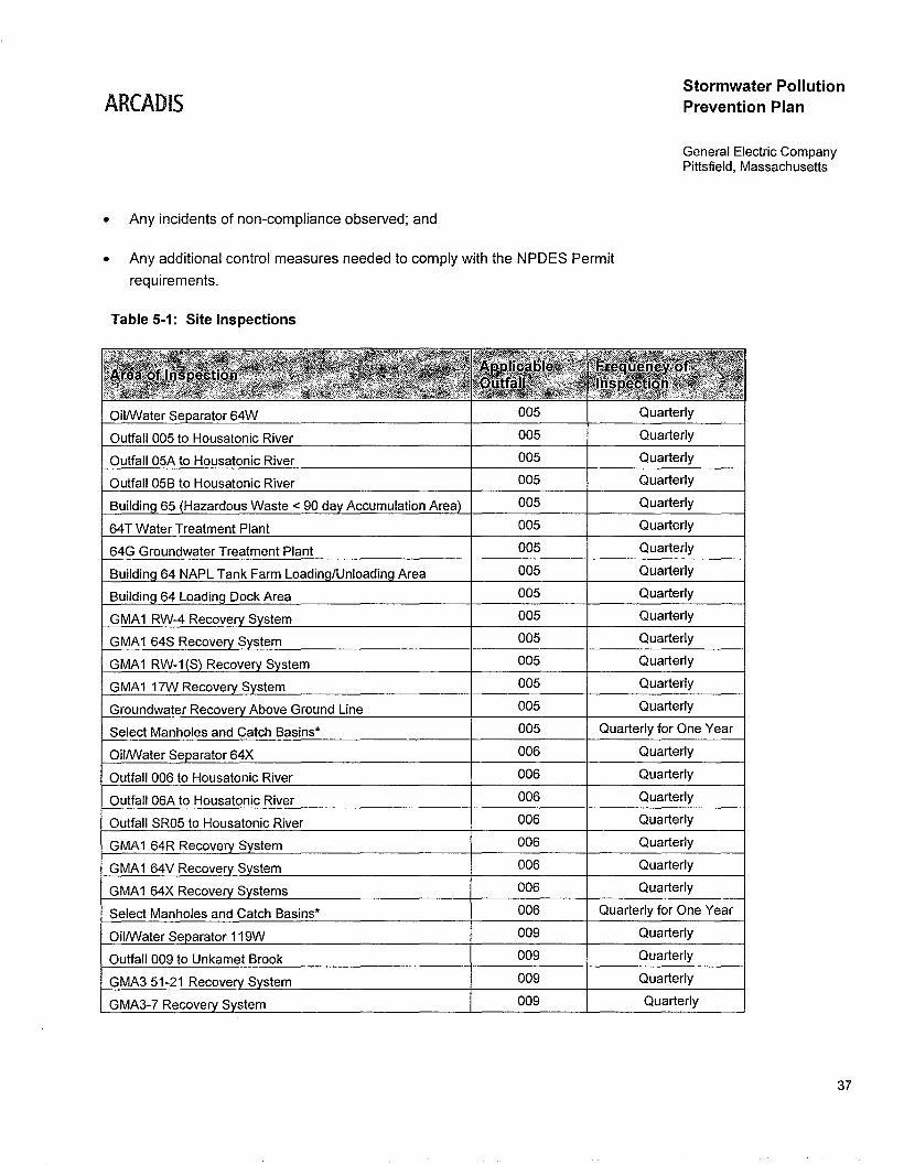
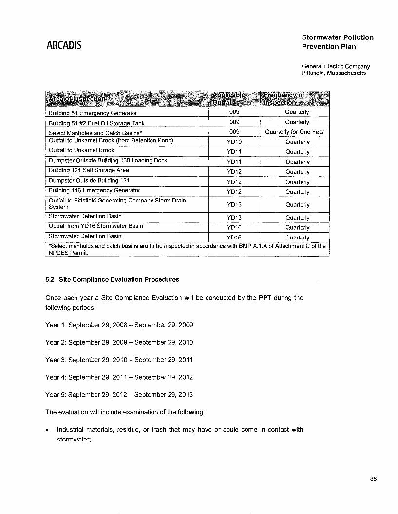
Table 5-1: Site Inspections
Stormwater PollutionPrevention Plan
General Electric CompanyPittsfield, Massachusetts
OillWater Se arator 64W 005 Quarterly
Outfall 005 to Housatonic River 005 Quarterly
Outfall 05A to Housatonic River 005 Quarterly
Outfall 05B to Housatonic River 005 Quarterly
Buildin 65 Hazardous Waste < 90 da Accumulation Area 005 Quarterly
64T Water Treatment Plant 005 Quarterly
64G Groundwater Treatment Plant 005 Quarterly
Area 005 Quarterly
005 Quarterly
005 Quarterly
005 Quarterly
005 Quarterly
005 Quarterly
005 Quarterly
Select Manholes and Catch Basins· 005 Quarterly for One Year
OillWater Se arator 64X 006 Quarterly
Outfall 006 to Housatonic River 006 Quarterly
Outfall 06A to Housatonic River 006 Quarterly
Outfall SR05 to Housatonic River 006 Quarterly
GMA1 64R Recove 006 Quarterly
GMA1 64V Recove 006 Quarterly
GMA1 64X Recove S stems 006 Quarterly
Select Manholes and Catch Basins· 006 Quarterly for One Year
OillWater Se arator 119W 009 Quarterly
Outfall 009 to Unkamet Brook 009 Quarterly
GMA3 51-21 Recove S stem 009 Quarterly
GMA3-7 Recove S stem 009 Quarterly
37
ARCADISStormwater PollutionPrevention Plan
General Electric CompanyPittsfield, Massachusetts
SelectManholes and Catch Basins*Outfall to Unkamet Brook (from Detention Pond)
Outfall to Unkamet Brook
Dumpster Outside Building 130 Loading Dock
Building 121 Salt Storage Area
Dumpster Outside Building 121
Building 116 Emergency Generator
Outfall to Pittsfield Generating Company Storm DrainSystem
009
009
009
YD10
YD11
YD11
YD12
YD12
YD12
YD13
Quarterly
Quarterly
Quarterly for One Year
Quarterly
Quarterly
Quarterly
Quarterly
Quarterly
Quarterly
Quarterly
Stormwater Detention Basin
Outfall from YD16 Stormwater Basin
YD13 Quarterly
YD16 Quarterly
Stormwater Detention Basin YD16 Quarterly
*Select manholes and catch basins are to be inspected in accordance with BMP A.1.A of Attachment C of theNPDES Permit.
5.2 Site Compliance Evaluation Procedures
Once each year a Site Compliance Evaluation will be conducted by the PPT during the
following periods:
Year 1: September 29, 2008 - September 29, 2009
Year 2: September 29,2009 - September 29,2010
Year 3: September 29,2010 - September 29,2011
Year 4: September 29,2011 - September 29,2012
Year 5: September 29,2012 - September 29,2013
The evaluation will include examination of the following:
• Industrial materials, residue, or trash that may have or could come in contact with
stormwater;
38
ARCADIS
• Leaks or spills from industrial equipment, drums, tanks, or other containers;
Stormwater PollutionPrevention Plan
General Electric CompanyPittsfield, Massachusetts
• Offsite tracking of industrial or waste materials, or sediment where vehicles enter or
exit the site;
• Tracking or blowing of raw, final or waste materials from areas of no exposure to
exposed areas;
• Evidence of pollutants discharging to surface waters at all site outfall(s), and the
condition of and around the outfall, including flow dissipation measures to prevent
scouring;
• Evidence of or potential for pollutants entering the site drainage system;
• Inspection of select manholes and catch basins, after the first year of quarterly
inspections, in Drainage Areas 005,006, and 009 (debris removal as necessary);
• Inspection (including debris measurement) of OWS 64W, 64X, 64Z, and 119W
(debris removal as necessary);
• Inspection of the following plugged outfalls at the site: YD4, YD5, YD7, YD8, YD9,
YD14, SR02, SR03, SR04, 007, and 09A; and
• Evaluation of the site's overall compliance with the NPDES Permit and the SWPPP.
At the completion of each Site Compliance Evaluation, an inspection report will be
prepared. The report must be kept on-site with this SWPPP. The report must include:
• Site name and physical address;
• NPDES Permit tracking number;
• Contact person name, title, and phone number;
• Date of the inspection;
• Personnel who participated in the inspection;
• Observations made;
39
ARCADJS
• Changes made to the SWPPP as a result of the Site Compliance Evaluation;
Stormwater PollutionPrevention Plan
General Electric CompanyPittsfield, Massachusetts
• Documentation of non-compliance situations observed and the response needed; and
• Signed Certificate of Compliance stating that the site is in compliance with the
NPDES Permit and the SWPPP.
The Annual Site Compliance Evaluation Report will be included in the revisedSWPPP submitted to EPA on an annual basis in accordance with the NPDESPermit. The Annual Site Compliance Evaluation may be used as one of theroutine site inspections as long as all components of both types of inspectionsare included.
40
ARCADIS
6. SWPPP Certifications
This section provides the following certifications in accordance with the MSGP:
• Facility Management Certification (MSGP-2008 Part 5.1.7 - Signature Requirements)
Stormwater PollutionPrevention Plan
General Electric CompanyPittsfield, Massachusetts
• Site Compliance Evaluation Certification (MSGP-2008 Part 4.3.2 -Comprehensive SiteInspection Documentation)
6.1 Facility Management Certification
I certify under penalty of law that this document and all attachments were
prepared under my direction in accordance with a system designed to ensure that
qualified personnel properly gathered and evaluated the information submitted.
Based on my inquiry of the persons who manage the system, or those persons
directly responsible for gathering the information, the information submitted is, to
the best of my knowledge and belief, true, accurate, and complete. I am aware
that there are significant penalties for submitting false information, including the
possibility of fine and imprisonment for knowing violations.
Yf(~ck.J r:~Michael T. Carroll
Manager of Pittsfield Remediation Programs
Date
41
ARCADIS
6.2 Site Compliance Evaluation Certification
Stormwater PollutionPrevention Plan
General Electric CompanyPittsfield, Massachusetts
I certify that the Site Compliance Evaluation required by MSGP-2008, as
incorporated into the NPDES Permit, was conducted on the date shown below by
the individual named below. In addition, I certify that the facility has and is
complying with .all provisions of the NPDES Permit and SWPPP.
I also certify under penalty of law that this document and all attachments were
prepared under my direction in accordance with a system designed to ensure that
qualified personnel properly gathered and evaluated the information submitted.
Based on my inquiry of the persons who manage the system, and those persons
directly responsible for gathering the information, the information submitted is, to
the best of my knowledge and belief, true, accurate, and complete. I am aware
that there are significant penalties for submitting false information, including the
possibility of fine and imprisonment for knowing violations.
1.
Signature of the Person Conducting the Evaluation
Site Compliance Evaluation Date:
SWPPP Revision Date:
2.
Signature of the Person Conducting the Evaluation
Site Compliance Evaluation Date:
SWPPP Revision Date:
42
ARCADIS
3.
Signature of the Person Conducting the Evaluation
Site Compliance Evaluation Date:
SWPPP Revision Date:
Stormwater PollutionPrevention Plan
General Electric CompanyPittsfield. Massachusetts
43
ARCADIS
7. SWPPP Modifications
This SWPPP will be amended whenever:
Stormwater PollutionPrevention Plan
General Electric CompanyPittsfield, Massachusetts
1. There is a change in design, construction, operation or maintenance that will have a
significant impact on the potential for the discharge of pollutants to the waters of the
United States;
2. If the SWPPP proves to be ineffective in eliminating or significantly minimizing
pollutants from sources; or
3. If the SWPPP proves to be ineffective in achieving the general objectives of
controlling pollutants in the site's stormwater discharges.
7.1 Corrective Action(s)
If situations of non-compliance are observed, the discovery of the non-compliance
condition must be documented within 24 hours of making such discovery. SUbsequently,
within 14 days of such discovery, the corrective action(s) to be 'taken to eliminate, or
further investigate, the deficiency is to be documented. If no corrective action is needed,
the basis for that determination is to be documented. If it is determined that changes are
necessary following the review, any modifications to control measures must be made
before the next storm event if possible, or as soon as practicable following the storm
event. A corrective action would be considered if any of the following non-compliance
conditions occur:
• Unauthorized release or discharge (e.g., spill, leak, or discharge of non-stormwater
not authorized by this permit) occurs at the site;
• Discharge violates a numeric effluent limit;
• GE or EPA determines that control measures are not stringent enough for the
discharge to meet applicable water quality standards; and
• GE determines that control measures are not being maintained properly, resulting in
non-compliance, during the routine facility inspection or comprehensive site
inspection.
44
ARCADIS
7.1.1 Corrective Action Report
Within 24 hours of discovery of a non-compliance condition, the following will bedocumented:
• Identification of the condition triggering the need for corrective action review;
• Description of the problem identified; and
• Date the problem was identified.
Within 14 days of discovery of a non-compliance condition, the following will bedocumented in a Corrective Action Report:
Stormwater PollutionPrevention Plan
General Electric CompanyPittsfield, Massachusetts
• Summary of corrective action taken or to be taken (or if corrective action is not
necessary, the basis for the determination);
• SWPPP modifications required as a result of the corrective action;
• Date corrective action initiated; and
• Date corrective action completed or expected to be completed.
This documentation will be submitted with the annual site compliance evaluation reportand a copy will be retained on-site with this SWPPP.
45
ARCADIS
8. References
ARCADIS BBL. 2007. Project Operations Plan.
Blasland, Bouck, & Lee, INC. 2000. Stormwater Management Plan.
Stormwater PollutionPrevention Plan
General Electric CompanyPittsfield, Massachusetts
MA Division of Fisheries & Wildlife. 2006. Massachusetts Natural Heritage Atlas, 1i h
Edition.
National Register Information System. 2009. Website accessed at: www.nr.nps.gov.
46

Figures
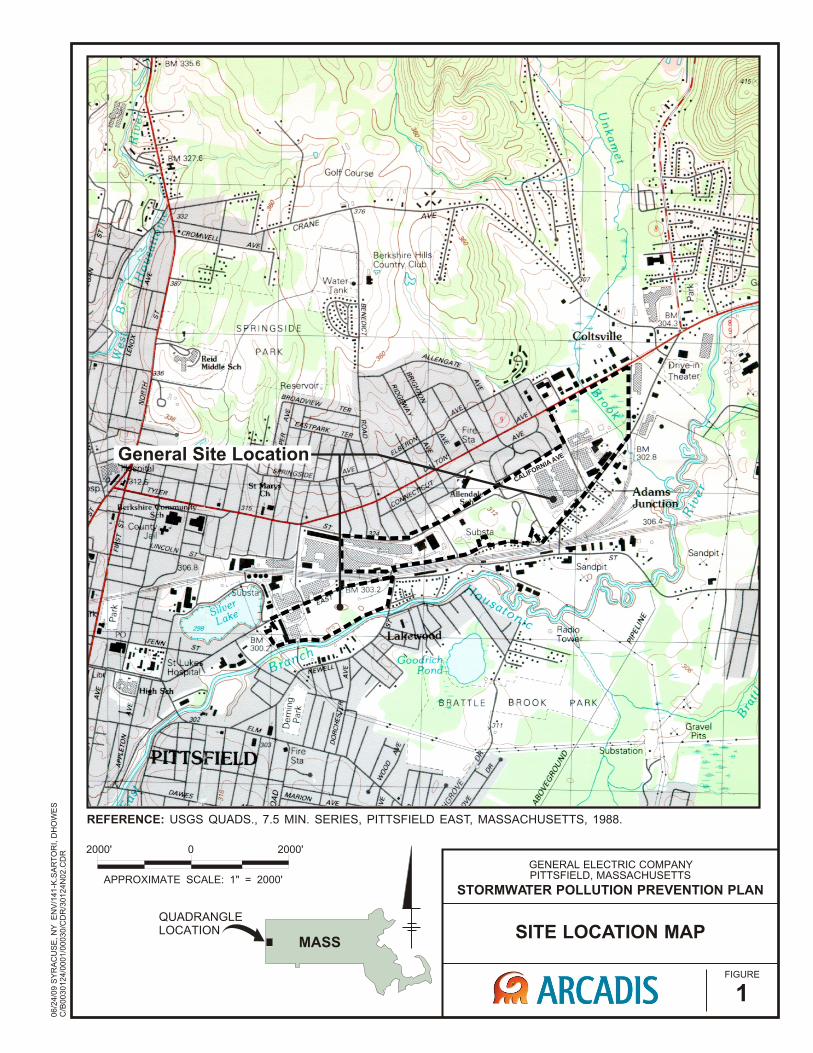
General Site LocationCALIFORNIA AVE
06
/24
/09
SY
RA
CU
SE
, N
Y E
NV
/14
1-K
.SA
RT
OR
I, D
HO
WE
SC
/B0
03
01
24
/00
01
/00
03
0/C
DR
/30
12
4N
02
.CD
R
SITE LOCATION MAP
FIGURE
1
GENERAL ELECTRIC COMPANYPITTSFIELD, MASSACHUSETTS
STORMWATER POLLUTION PREVENTION PLANAPPROXIMATE SCALE: 1" = 2000'
2000'0 2000'
QUADRANGLE LOCATION
MASS
REFERENCE: USGS QUADS., 7.5 MIN. SERIES, PITTSFIELD EAST, MASSACHUSETTS, 1988.

Appendices
Appendix A
NPDES Permit No. MA0003891
NPDES Permit No. MA0003891
Page 1 of 24
AUTHORIZATION TO DISCHARGE UNDER THE NATIONAL POLLUTANT DISCHARGE ELIMINATION SYSTEM
In compliance with the provisions of the Federal Clean Water Act as amended (33 U.S.C. '' 1251 et seq.; the “CWA”), and the Massachusetts Clean Waters Act, as amended, (M.G.L. Chap. 21, '' 26-53),
General Electric Company 159 Plastics Avenue Pittsfield, MA 01201
is authorized to discharge from the facility located at
General Electric Company 159 Plastics Avenue Pittsfield, MA 01201 (See also: Attachment A)
to receiving waters named the
Housatonic River, Unkamet Brook (Housatonic River Watershed)
in accordance with effluent limitations, monitoring requirements and other conditions set forth herein. This permit will become effective on December 1, 2008. This permit and the authorization to discharge expire at midnight, five (5) years from the effective date. This permit supersedes the permit issued on September 30, 1988, which became effective on February 7, 1992, was modified on May 21, 1992, and expired on February 7, 1997. This permit consists of 24 pages in Part I including effluent limitations, monitoring requirements, Attachments A (list of outfalls), B (toxicity protocol), C (Best Management Practices requirements), D (PCB method specification), E (Example Effluent Monitoring Summary Table) and 25 pages in Part II including Standard Conditions and Definitions. Signed this 30th day of September, 2008 /s/ SIGNATURE ON FILE _________________________ __________________________ Director Director Office of Ecosystem Protection Division of Watershed Management Environmental Protection Agency Department of Environmental Protection Boston, MA Commonwealth of Massachusetts
Boston, MA
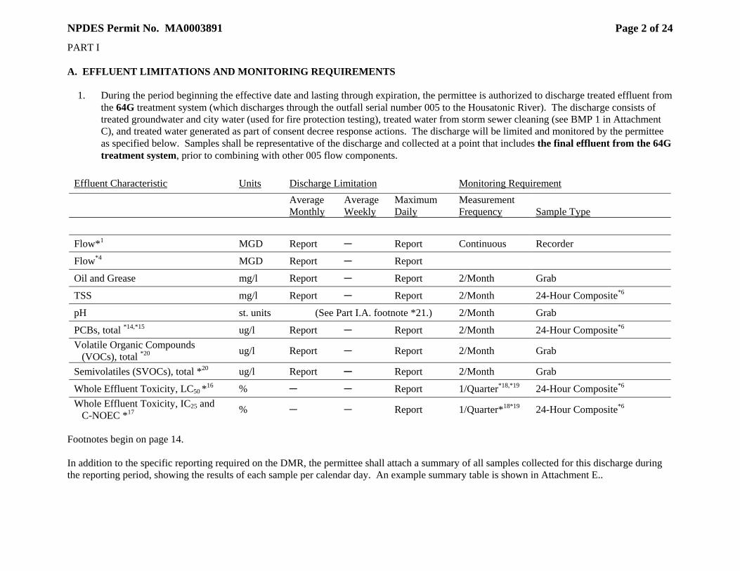
NPDES Permit No. MA0003891
Page 2 of 24
PART I A. EFFLUENT LIMITATIONS AND MONITORING REQUIREMENTS 1. During the period beginning the effective date and lasting through expiration, the permittee is authorized to discharge treated effluent from
the 64G treatment system (which discharges through the outfall serial number 005 to the Housatonic River). The discharge consists of treated groundwater and city water (used for fire protection testing), treated water from storm sewer cleaning (see BMP 1 in Attachment C), and treated water generated as part of consent decree response actions. The discharge will be limited and monitored by the permittee as specified below. Samples shall be representative of the discharge and collected at a point that includes the final effluent from the 64G treatment system, prior to combining with other 005 flow components.
Effluent Characteristic Units Discharge Limitation Monitoring Requirement
Average Monthly
Average Weekly
Maximum Daily
Measurement Frequency
Sample Type
Flow*1 MGD Report C Report Continuous Recorder
Flow*4 MGD Report C Report
Oil and Grease mg/l Report C Report 2/Month Grab
TSS mg/l Report C Report 2/Month 24-Hour Composite*6
pH st. units (See Part I.A. footnote *21.) 2/Month Grab
PCBs, total *14,*15 ug/l Report C Report 2/Month 24-Hour Composite*6 Volatile Organic Compounds (VOCs), total *20 ug/l Report C Report 2/Month Grab
Semivolatiles (SVOCs), total *20 ug/l Report C Report 2/Month Grab
Whole Effluent Toxicity, LC50 *16 % C C Report 1/Quarter*18,*19 24-Hour Composite*6 Whole Effluent Toxicity, IC25 and C-NOEC *17 % C C Report 1/Quarter*18*19 24-Hour Composite*6
Footnotes begin on page 14. In addition to the specific reporting required on the DMR, the permittee shall attach a summary of all samples collected for this discharge during the reporting period, showing the results of each sample per calendar day. An example summary table is shown in Attachment E..
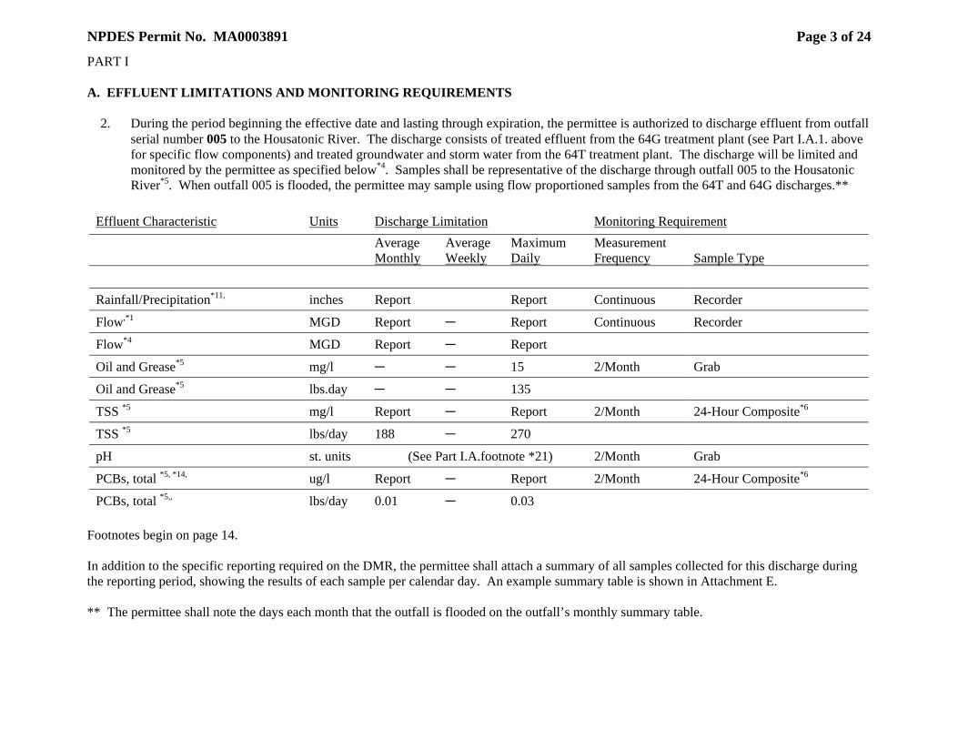
NPDES Permit No. MA0003891
Page 3 of 24
PART I A. EFFLUENT LIMITATIONS AND MONITORING REQUIREMENTS 2. During the period beginning the effective date and lasting through expiration, the permittee is authorized to discharge effluent from outfall
serial number 005 to the Housatonic River. The discharge consists of treated effluent from the 64G treatment plant (see Part I.A.1. above for specific flow components) and treated groundwater and storm water from the 64T treatment plant. The discharge will be limited and monitored by the permittee as specified below*4. Samples shall be representative of the discharge through outfall 005 to the Housatonic River*5. When outfall 005 is flooded, the permittee may sample using flow proportioned samples from the 64T and 64G discharges.**
Effluent Characteristic Units Discharge Limitation Monitoring Requirement
Average Monthly
Average Weekly
Maximum Daily
Measurement Frequency
Sample Type
Rainfall/Precipitation*11, inches Report Report Continuous Recorder
Flow,*1 MGD Report C Report Continuous Recorder
Flow*4 MGD Report C Report
Oil and Grease*5 mg/l C C 15 2/Month Grab
Oil and Grease*5 lbs.day C C 135
TSS *5 mg/l Report C Report 2/Month 24-Hour Composite*6
TSS *5 lbs/day 188 C 270
pH st. units (See Part I.A.footnote *21) 2/Month Grab
PCBs, total *5, *14, ug/l Report C Report 2/Month 24-Hour Composite*6
PCBs, total *5,, lbs/day 0.01 C 0.03 Footnotes begin on page 14. In addition to the specific reporting required on the DMR, the permittee shall attach a summary of all samples collected for this discharge during the reporting period, showing the results of each sample per calendar day. An example summary table is shown in Attachment E. ** The permittee shall note the days each month that the outfall is flooded on the outfall’s monthly summary table.
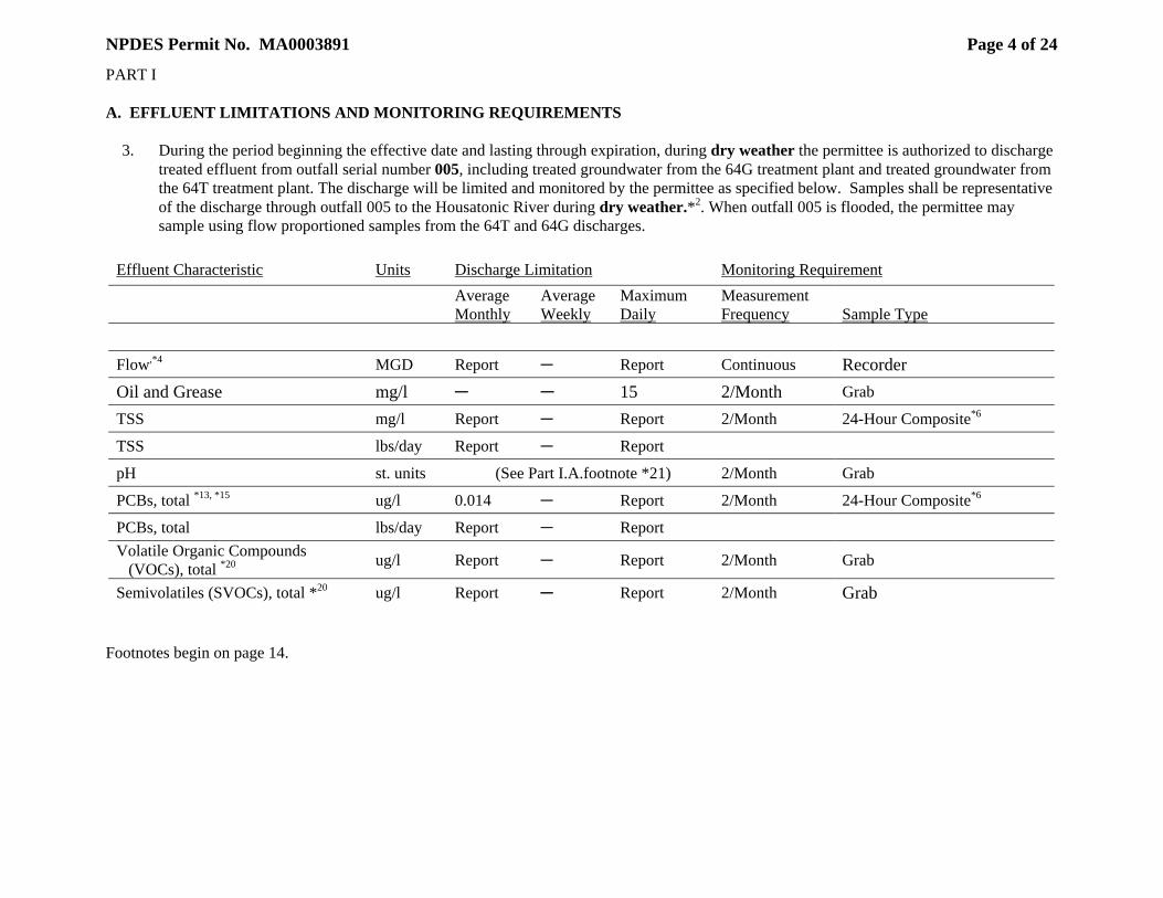
NPDES Permit No. MA0003891
Page 4 of 24
PART I A. EFFLUENT LIMITATIONS AND MONITORING REQUIREMENTS 3. During the period beginning the effective date and lasting through expiration, during dry weather the permittee is authorized to discharge
treated effluent from outfall serial number 005, including treated groundwater from the 64G treatment plant and treated groundwater from the 64T treatment plant. The discharge will be limited and monitored by the permittee as specified below. Samples shall be representative of the discharge through outfall 005 to the Housatonic River during dry weather.*2. When outfall 005 is flooded, the permittee may sample using flow proportioned samples from the 64T and 64G discharges.
Effluent Characteristic Units Discharge Limitation Monitoring Requirement
Average Monthly
Average Weekly
Maximum Daily
Measurement Frequency
Sample Type
Flow,*4 MGD Report C Report Continuous Recorder Oil and Grease mg/l C C 15 2/Month Grab
TSS mg/l Report C Report 2/Month 24-Hour Composite*6
TSS lbs/day Report C Report
pH st. units (See Part I.A.footnote *21) 2/Month Grab
PCBs, total *13, *15 ug/l 0.014 C Report 2/Month 24-Hour Composite*6
PCBs, total lbs/day Report C Report Volatile Organic Compounds (VOCs), total *20 ug/l Report C Report 2/Month Grab
Semivolatiles (SVOCs), total *20 ug/l Report C Report 2/Month Grab Footnotes begin on page 14.
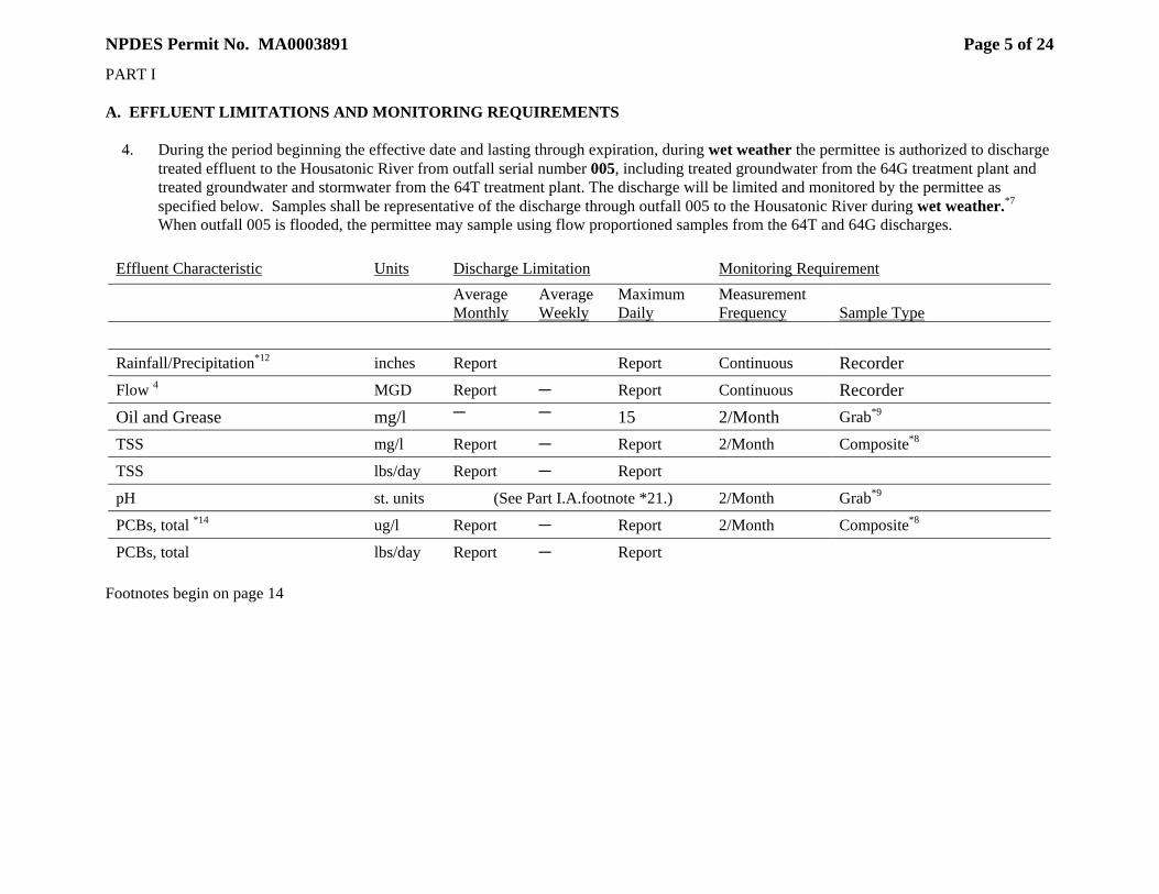
NPDES Permit No. MA0003891
Page 5 of 24
PART I A. EFFLUENT LIMITATIONS AND MONITORING REQUIREMENTS 4. During the period beginning the effective date and lasting through expiration, during wet weather the permittee is authorized to discharge
treated effluent to the Housatonic River from outfall serial number 005, including treated groundwater from the 64G treatment plant and treated groundwater and stormwater from the 64T treatment plant. The discharge will be limited and monitored by the permittee as specified below. Samples shall be representative of the discharge through outfall 005 to the Housatonic River during wet weather.*7
When outfall 005 is flooded, the permittee may sample using flow proportioned samples from the 64T and 64G discharges.
Effluent Characteristic Units Discharge Limitation Monitoring Requirement
Average Monthly
Average Weekly
Maximum Daily
Measurement Frequency
Sample Type
Rainfall/Precipitation*12 inches Report Report Continuous Recorder Flow 4 MGD Report C Report Continuous Recorder Oil and Grease mg/l C C 15 2/Month Grab*9
TSS mg/l Report C Report 2/Month Composite*8
TSS lbs/day Report C Report
pH st. units (See Part I.A.footnote *21.) 2/Month Grab*9
PCBs, total *14 ug/l Report C Report 2/Month Composite*8
PCBs, total lbs/day Report C Report Footnotes begin on page 14
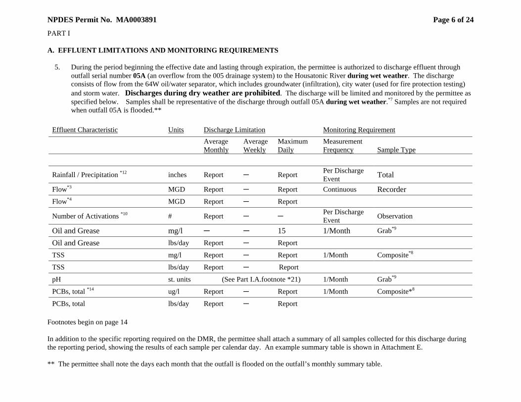
NPDES Permit No. MA0003891
Page 6 of 24
PART I A. EFFLUENT LIMITATIONS AND MONITORING REQUIREMENTS 5. During the period beginning the effective date and lasting through expiration, the permittee is authorized to discharge effluent through
outfall serial number 05A (an overflow from the 005 drainage system) to the Housatonic River during wet weather. The discharge consists of flow from the 64W oil/water separator, which includes groundwater (infiltration), city water (used for fire protection testing) and storm water. Discharges during dry weather are prohibited. The discharge will be limited and monitored by the permittee as specified below. Samples shall be representative of the discharge through outfall 05A during wet weather.*7 Samples are not required when outfall 05A is flooded.**
Effluent Characteristic Units Discharge Limitation Monitoring Requirement
Average Monthly
Average Weekly
Maximum Daily
Measurement Frequency
Sample Type
Rainfall / Precipitation *12 inches Report C Report Per Discharge Event Total
Flow*3 MGD Report C Report Continuous Recorder Flow*4 MGD Report C Report
Number of Activations *10 # Report C C Per Discharge Event Observation
Oil and Grease mg/l C C 15 1/Month Grab*9
Oil and Grease lbs/day Report C Report
TSS mg/l Report C Report 1/Month Composite*8
TSS lbs/day Report C Report
pH st. units (See Part I.A.footnote *21) 1/Month Grab*9
PCBs, total *14 ug/l Report C Report 1/Month Composite*8
PCBs, total lbs/day Report C Report Footnotes begin on page 14 In addition to the specific reporting required on the DMR, the permittee shall attach a summary of all samples collected for this discharge during the reporting period, showing the results of each sample per calendar day. An example summary table is shown in Attachment E. ** The permittee shall note the days each month that the outfall is flooded on the outfall’s monthly summary table.
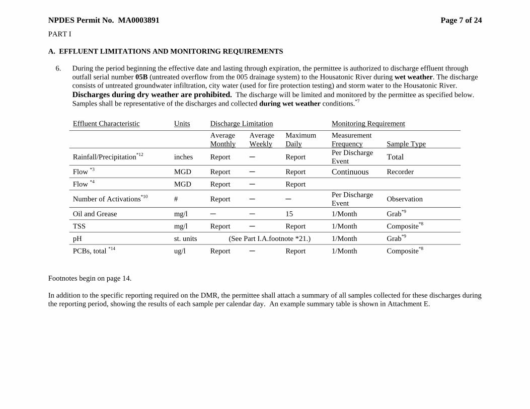
NPDES Permit No. MA0003891
Page 7 of 24
PART I A. EFFLUENT LIMITATIONS AND MONITORING REQUIREMENTS 6. During the period beginning the effective date and lasting through expiration, the permittee is authorized to discharge effluent through
outfall serial number 05B (untreated overflow from the 005 drainage system) to the Housatonic River during wet weather. The discharge consists of untreated groundwater infiltration, city water (used for fire protection testing) and storm water to the Housatonic River. Discharges during dry weather are prohibited. The discharge will be limited and monitored by the permittee as specified below. Samples shall be representative of the discharges and collected during wet weather conditions.*7
Effluent Characteristic Units Discharge Limitation Monitoring Requirement
Average Monthly
Average Weekly
Maximum Daily
Measurement Frequency
Sample Type
Rainfall/Precipitation*12 inches Report C Report Per Discharge Event Total
Flow *3 MGD Report C Report Continuous Recorder
Flow *4 MGD Report C Report
Number of Activations*10 # Report C C Per Discharge Event Observation
Oil and Grease mg/l C C 15 1/Month Grab*9
TSS mg/l Report C Report 1/Month Composite*8
pH st. units (See Part I.A.footnote *21.) 1/Month Grab*9
PCBs, total *14 ug/l Report C Report 1/Month Composite*8 Footnotes begin on page 14. In addition to the specific reporting required on the DMR, the permittee shall attach a summary of all samples collected for these discharges during the reporting period, showing the results of each sample per calendar day. An example summary table is shown in Attachment E.
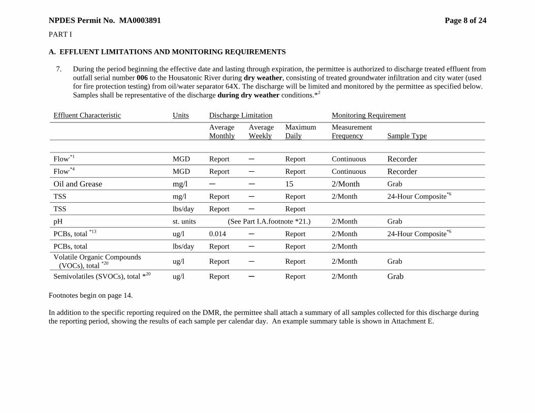
NPDES Permit No. MA0003891
Page 8 of 24
PART I A. EFFLUENT LIMITATIONS AND MONITORING REQUIREMENTS 7. During the period beginning the effective date and lasting through expiration, the permittee is authorized to discharge treated effluent from
outfall serial number 006 to the Housatonic River during dry weather, consisting of treated groundwater infiltration and city water (used for fire protection testing) from oil/water separator 64X. The discharge will be limited and monitored by the permittee as specified below. Samples shall be representative of the discharge during dry weather conditions.*2
Effluent Characteristic Units Discharge Limitation Monitoring Requirement
Average Monthly
Average Weekly
Maximum Daily
Measurement Frequency
Sample Type
Flow,*1 MGD Report C Report Continuous Recorder Flow,*4 MGD Report C Report Continuous Recorder Oil and Grease mg/l C C 15 2/Month Grab
TSS mg/l Report C Report 2/Month 24-Hour Composite*6
TSS lbs/day Report C Report
pH st. units (See Part I.A.footnote *21.) 2/Month Grab
PCBs, total *13 ug/l 0.014 C Report 2/Month 24-Hour Composite*6
PCBs, total lbs/day Report C Report 2/Month Volatile Organic Compounds (VOCs), total *20 ug/l Report C Report 2/Month Grab
Semivolatiles (SVOCs), total *20 ug/l Report C Report 2/Month Grab Footnotes begin on page 14. In addition to the specific reporting required on the DMR, the permittee shall attach a summary of all samples collected for this discharge during the reporting period, showing the results of each sample per calendar day. An example summary table is shown in Attachment E.
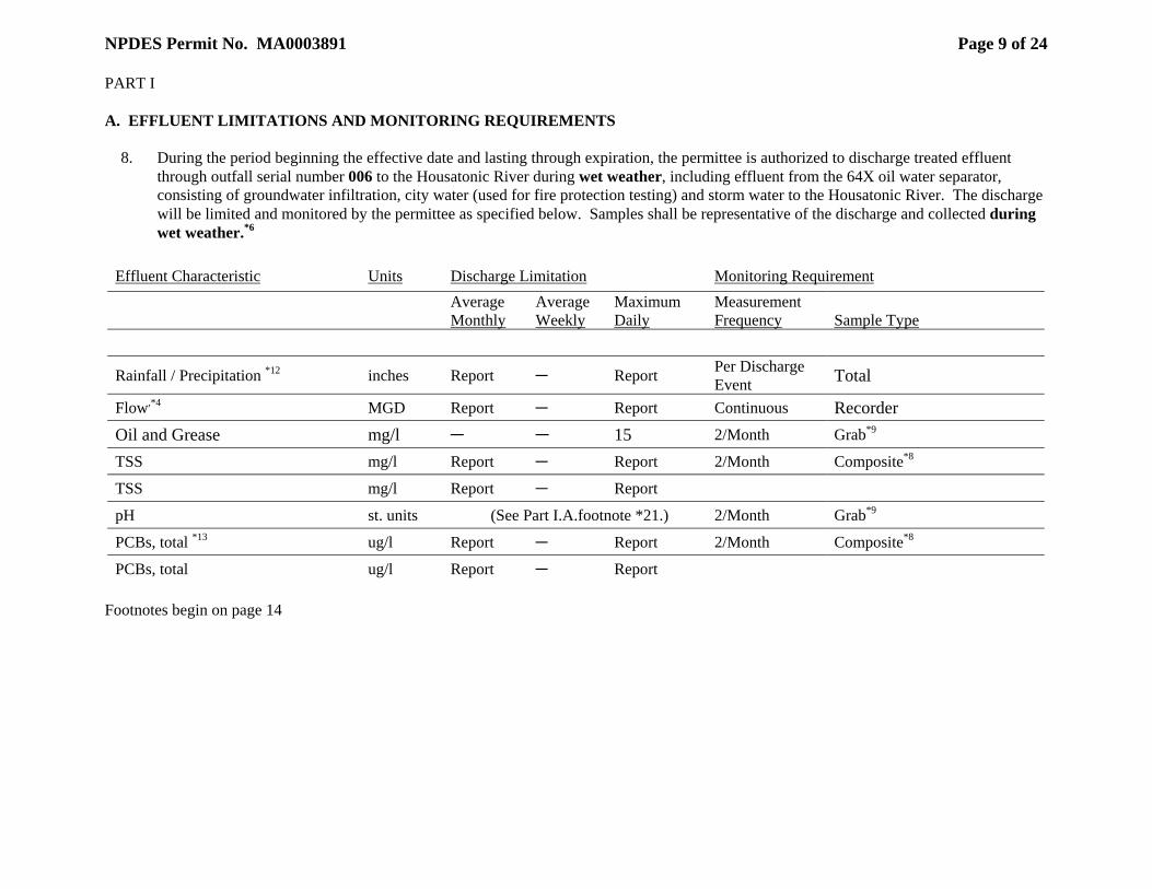
NPDES Permit No. MA0003891
Page 9 of 24
PART I A. EFFLUENT LIMITATIONS AND MONITORING REQUIREMENTS 8. During the period beginning the effective date and lasting through expiration, the permittee is authorized to discharge treated effluent
through outfall serial number 006 to the Housatonic River during wet weather, including effluent from the 64X oil water separator, consisting of groundwater infiltration, city water (used for fire protection testing) and storm water to the Housatonic River. The discharge will be limited and monitored by the permittee as specified below. Samples shall be representative of the discharge and collected during wet weather.*6
Effluent Characteristic Units Discharge Limitation Monitoring Requirement
Average Monthly
Average Weekly
Maximum Daily
Measurement Frequency
Sample Type
Rainfall / Precipitation *12 inches Report C Report Per Discharge Event Total
Flow,*4 MGD Report C Report Continuous Recorder Oil and Grease mg/l C C 15 2/Month Grab*9
TSS mg/l Report C Report 2/Month Composite*8
TSS mg/l Report C Report
pH st. units (See Part I.A.footnote *21.) 2/Month Grab*9
PCBs, total *13 ug/l Report C Report 2/Month Composite*8
PCBs, total ug/l Report C Report Footnotes begin on page 14

NPDES Permit No. MA0003891
Page 10 of 24
PART I A. EFFLUENT LIMITATIONS AND MONITORING REQUIREMENTS 9. During the period beginning the effective date and lasting through expiration, the permittee is authorized to discharge effluent from
outfalls serial numbers 06A and SR05 (flows from the 006 drainage system that exceed the capacity of OWS64X and its related piping capacity) consisting of untreated groundwater infiltration, city water (used for fire protection testing) and storm water to the Housatonic River during wet weather. The discharges will be limited and monitored by the permittee as specified below. Discharges during dry weather are prohibited. Samples shall be representative of the discharge and collected during wet weather. * 7
Effluent Characteristic Outfall Units Discharge Limitation Monitoring Requirement
Average Monthly
Average Weekly
Maximum Daily
Measurement Frequency
Sample Type
Rainfall/Precipitation *12 06A, SR05 inches Report* C Report* Per Discharge
Event Total
Flow,*4 SR05 MGD Report C Report Per Discharge Event Recorder
Flow,*3 06A MGD Report C Report Continuous Recorder Flow,*4 06A MGD Report C Report
Number of Activations*10 06A, SR05 # Report C C Per Discharge
Event Observation
Oil and Grease 06A mg/l Report C 15 1/Month Grab*9
TSS 06A mg/l Report C Report 1/Month Composite*8
TSS 06A lbs/day Report C Report
pH 06A st. units (See Part I.A.footnote *21.) 1/Month Grab*9
PCBs, total *14 06A ug/l Report C Report 1/Month Composite*8
PCBs, total 06A lbs/day Report C Report Footnotes begin on page 14. In addition to the specific reporting required on the DMR, the permittee shall attach a summary of all samples collected for these discharges during the reporting period, showing the results of each sample per calendar day. An example summary table is shown in Attachment E.
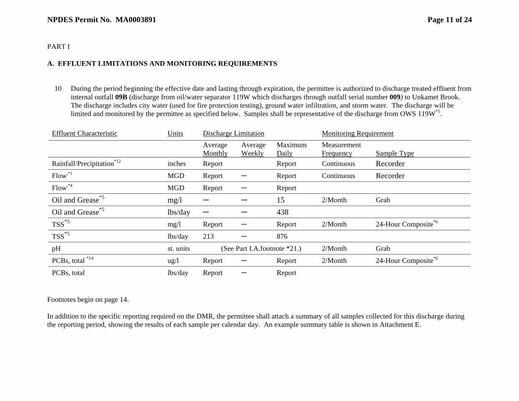
NPDES Permit No. MA0003891
Page 11 of 24
PART I A. EFFLUENT LIMITATIONS AND MONITORING REQUIREMENTS
10 During the period beginning the effective date and lasting through expiration, the permittee is authorized to discharge treated effluent from
internal outfall 09B (discharge from oil/water separator 119W which discharges through outfall serial number 009) to Unkamet Brook. The discharge includes city water (used for fire protection testing), ground water infiltration, and storm water. The discharge will be limited and monitored by the permittee as specified below. Samples shall be representative of the discharge from OWS 119W*5.
Effluent Characteristic Units Discharge Limitation Monitoring Requirement
Average Monthly
Average Weekly
Maximum Daily
Measurement Frequency
Sample Type
Rainfall/Precipitation*12 inches Report Report Continuous Recorder Flow,*1 MGD Report C Report Continuous Recorder Flow,*4 MGD Report C Report Oil and Grease*5 mg/l C C 15 2/Month Grab
Oil and Grease*5 lbs/day C C 438
TSS*5 mg/l Report C Report 2/Month 24-Hour Composite*6
TSS*5 lbs/day 213 C 876
pH st. units (See Part I.A.footnote *21.) 2/Month Grab
PCBs, total *14 ug/l Report C Report 2/Month 24-Hour Composite*6
PCBs, total lbs/day Report C Report Footnotes begin on page 14. In addition to the specific reporting required on the DMR, the permittee shall attach a summary of all samples collected for this discharge during the reporting period, showing the results of each sample per calendar day. An example summary table is shown in Attachment E.
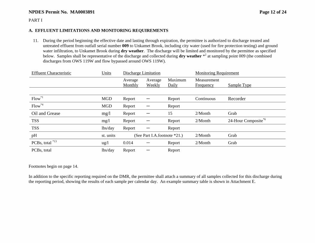
NPDES Permit No. MA0003891
Page 12 of 24
PART I A. EFFLUENT LIMITATIONS AND MONITORING REQUIREMENTS 11. During the period beginning the effective date and lasting through expiration, the permittee is authorized to discharge treated and
untreated effluent from outfall serial number 009 to Unkamet Brook, including city water (used for fire protection testing) and ground water infiltration, to Unkamet Brook during dry weather. The discharge will be limited and monitored by the permittee as specified below. Samples shall be representative of the discharge and collected during dry weather *2 at sampling point 009 (the combined discharges from OWS 119W and flow bypassed around OWS 119W).
Effluent Characteristic Units Discharge Limitation Monitoring Requirement
Average Monthly
Average Weekly
Maximum Daily
Measurement Frequency
Sample Type
Flow*1 MGD Report C Report Continuous Recorder Flow*4 MGD Report C Report Oil and Grease mg/l Report C 15 2/Month Grab
TSS mg/l Report C Report 2/Month 24-Hour Composite*6
TSS lbs/day Report C Report
pH st. units (See Part I.A.footnote *21.) 2/Month Grab
PCBs, total *13 ug/l 0.014 C Report 2/Month Grab
PCBs, total lbs/day Report C Report Footnotes begin on page 14. In addition to the specific reporting required on the DMR, the permittee shall attach a summary of all samples collected for this discharge during the reporting period, showing the results of each sample per calendar day. An example summary table is shown in Attachment E.
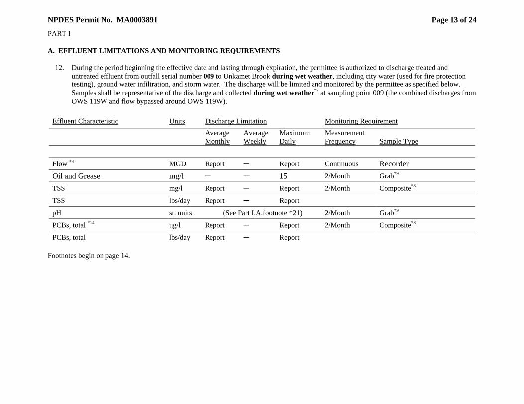
NPDES Permit No. MA0003891
Page 13 of 24
PART I A. EFFLUENT LIMITATIONS AND MONITORING REQUIREMENTS 12. During the period beginning the effective date and lasting through expiration, the permittee is authorized to discharge treated and
untreated effluent from outfall serial number 009 to Unkamet Brook during wet weather, including city water (used for fire protection testing), ground water infiltration, and storm water. The discharge will be limited and monitored by the permittee as specified below. Samples shall be representative of the discharge and collected during wet weather*7 at sampling point 009 (the combined discharges from OWS 119W and flow bypassed around OWS 119W).
Effluent Characteristic Units Discharge Limitation Monitoring Requirement
Average Monthly
Average Weekly
Maximum Daily
Measurement Frequency
Sample Type
Flow *4 MGD Report C Report Continuous Recorder Oil and Grease mg/l C C 15 2/Month Grab*9
TSS mg/l Report C Report 2/Month Composite*8
TSS lbs/day Report C Report
pH st. units (See Part I.A.footnote *21) 2/Month Grab*9
PCBs, total *14 ug/l Report C Report 2/Month Composite*8
PCBs, total lbs/day Report C Report Footnotes begin on page 14.
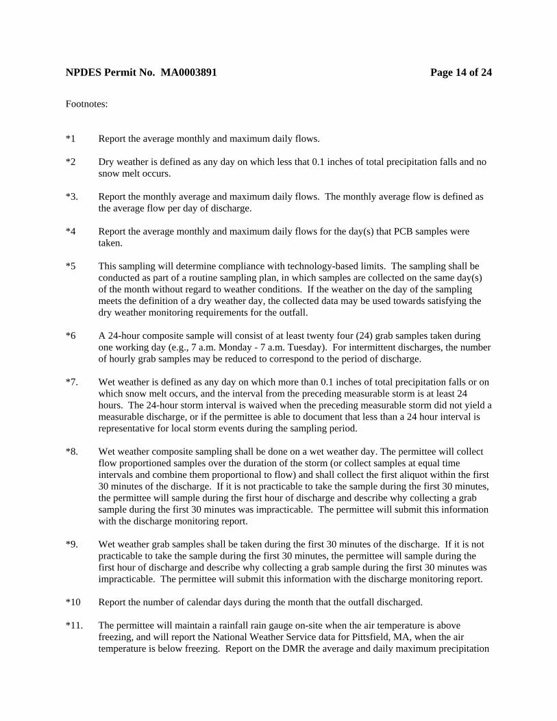
NPDES Permit No. MA0003891
Page 14 of 24
Footnotes: *1 Report the average monthly and maximum daily flows. *2 Dry weather is defined as any day on which less that 0.1 inches of total precipitation falls and no
snow melt occurs. *3. Report the monthly average and maximum daily flows. The monthly average flow is defined as
the average flow per day of discharge. *4 Report the average monthly and maximum daily flows for the day(s) that PCB samples were
taken. *5 This sampling will determine compliance with technology-based limits. The sampling shall be
conducted as part of a routine sampling plan, in which samples are collected on the same day(s) of the month without regard to weather conditions. If the weather on the day of the sampling meets the definition of a dry weather day, the collected data may be used towards satisfying the dry weather monitoring requirements for the outfall.
*6 A 24-hour composite sample will consist of at least twenty four (24) grab samples taken during
one working day (e.g., 7 a.m. Monday - 7 a.m. Tuesday). For intermittent discharges, the number of hourly grab samples may be reduced to correspond to the period of discharge.
*7. Wet weather is defined as any day on which more than 0.1 inches of total precipitation falls or on
which snow melt occurs, and the interval from the preceding measurable storm is at least 24 hours. The 24-hour storm interval is waived when the preceding measurable storm did not yield a measurable discharge, or if the permittee is able to document that less than a 24 hour interval is representative for local storm events during the sampling period.
*8. Wet weather composite sampling shall be done on a wet weather day. The permittee will collect
flow proportioned samples over the duration of the storm (or collect samples at equal time intervals and combine them proportional to flow) and shall collect the first aliquot within the first 30 minutes of the discharge. If it is not practicable to take the sample during the first 30 minutes, the permittee will sample during the first hour of discharge and describe why collecting a grab sample during the first 30 minutes was impracticable. The permittee will submit this information with the discharge monitoring report.
*9. Wet weather grab samples shall be taken during the first 30 minutes of the discharge. If it is not
practicable to take the sample during the first 30 minutes, the permittee will sample during the first hour of discharge and describe why collecting a grab sample during the first 30 minutes was impracticable. The permittee will submit this information with the discharge monitoring report.
*10 Report the number of calendar days during the month that the outfall discharged. *11. The permittee will maintain a rainfall rain gauge on-site when the air temperature is above
freezing, and will report the National Weather Service data for Pittsfield, MA, when the air temperature is below freezing. Report on the DMR the average and daily maximum precipitation
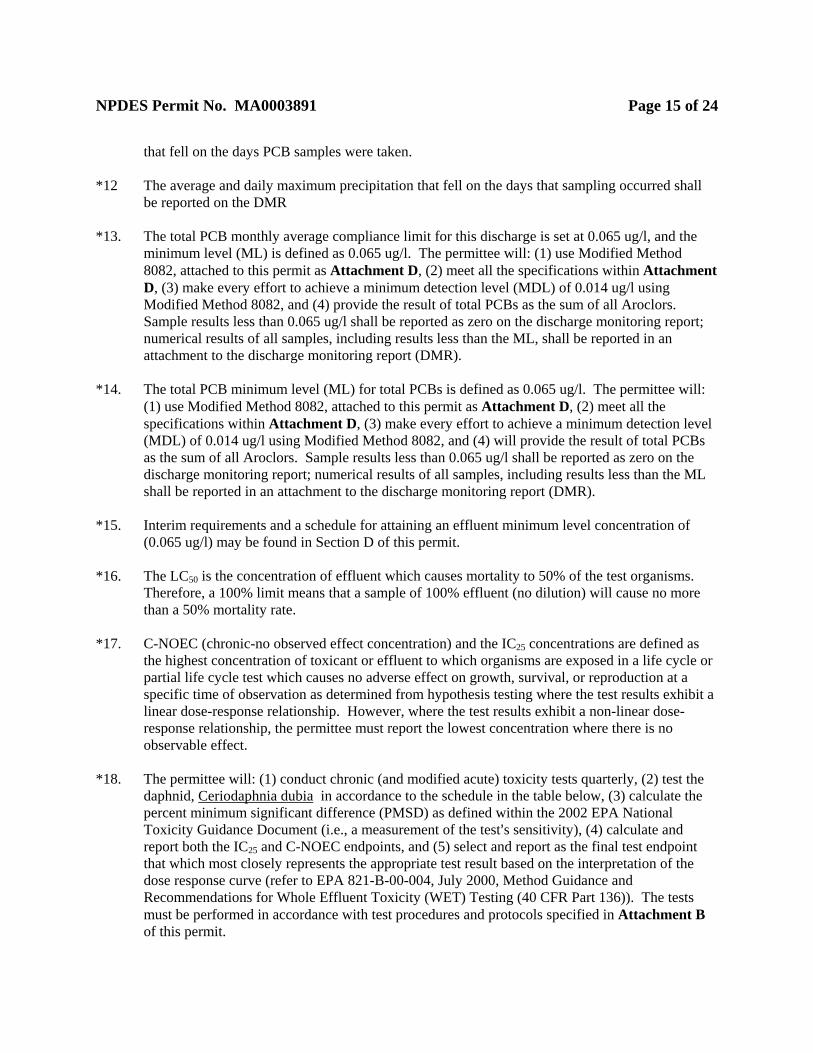
NPDES Permit No. MA0003891
Page 15 of 24
that fell on the days PCB samples were taken. *12 The average and daily maximum precipitation that fell on the days that sampling occurred shall
be reported on the DMR
*13. The total PCB monthly average compliance limit for this discharge is set at 0.065 ug/l, and the minimum level (ML) is defined as 0.065 ug/l. The permittee will: (1) use Modified Method 8082, attached to this permit as Attachment D, (2) meet all the specifications within Attachment D, (3) make every effort to achieve a minimum detection level (MDL) of 0.014 ug/l using Modified Method 8082, and (4) provide the result of total PCBs as the sum of all Aroclors. Sample results less than 0.065 ug/l shall be reported as zero on the discharge monitoring report; numerical results of all samples, including results less than the ML, shall be reported in an attachment to the discharge monitoring report (DMR).
*14. The total PCB minimum level (ML) for total PCBs is defined as 0.065 ug/l. The permittee will:
(1) use Modified Method 8082, attached to this permit as Attachment D, (2) meet all the specifications within Attachment D, (3) make every effort to achieve a minimum detection level (MDL) of 0.014 ug/l using Modified Method 8082, and (4) will provide the result of total PCBs as the sum of all Aroclors. Sample results less than 0.065 ug/l shall be reported as zero on the discharge monitoring report; numerical results of all samples, including results less than the ML shall be reported in an attachment to the discharge monitoring report (DMR).
*15. Interim requirements and a schedule for attaining an effluent minimum level concentration of
(0.065 ug/l) may be found in Section D of this permit. *16. The LC50 is the concentration of effluent which causes mortality to 50% of the test organisms.
Therefore, a 100% limit means that a sample of 100% effluent (no dilution) will cause no more than a 50% mortality rate.
*17. C-NOEC (chronic-no observed effect concentration) and the IC25 concentrations are defined as
the highest concentration of toxicant or effluent to which organisms are exposed in a life cycle or partial life cycle test which causes no adverse effect on growth, survival, or reproduction at a specific time of observation as determined from hypothesis testing where the test results exhibit a linear dose-response relationship. However, where the test results exhibit a non-linear dose-response relationship, the permittee must report the lowest concentration where there is no observable effect.
*18. The permittee will: (1) conduct chronic (and modified acute) toxicity tests quarterly, (2) test the
daphnid, Ceriodaphnia dubia in accordance to the schedule in the table below, (3) calculate the percent minimum significant difference (PMSD) as defined within the 2002 EPA National Toxicity Guidance Document (i.e., a measurement of the test=s sensitivity), (4) calculate and report both the IC25 and C-NOEC endpoints, and (5) select and report as the final test endpoint that which most closely represents the appropriate test result based on the interpretation of the dose response curve (refer to EPA 821-B-00-004, July 2000, Method Guidance and Recommendations for Whole Effluent Toxicity (WET) Testing (40 CFR Part 136)). The tests must be performed in accordance with test procedures and protocols specified in Attachment B of this permit.
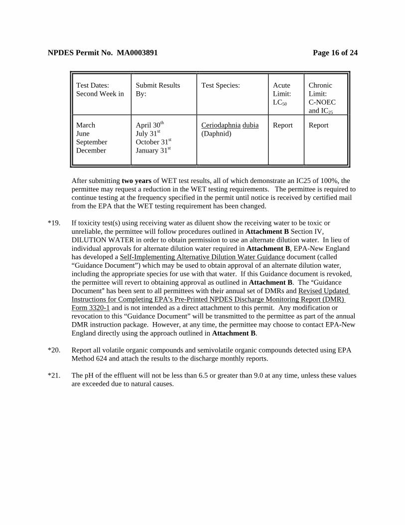
NPDES Permit No. MA0003891
Page 16 of 24
Test Dates: Second Week in
Submit Results By:
Test Species:
Acute Limit: LC50
Chronic Limit: C-NOEC and IC25
March June September December
April 30th July 31st October 31st January 31st
Ceriodaphnia dubia (Daphnid)
Report
Report
After submitting two years of WET test results, all of which demonstrate an IC25 of 100%, the permittee may request a reduction in the WET testing requirements. The permittee is required to continue testing at the frequency specified in the permit until notice is received by certified mail from the EPA that the WET testing requirement has been changed.
*19. If toxicity test(s) using receiving water as diluent show the receiving water to be toxic or
unreliable, the permittee will follow procedures outlined in Attachment B Section IV, DILUTION WATER in order to obtain permission to use an alternate dilution water. In lieu of individual approvals for alternate dilution water required in Attachment B, EPA-New England has developed a Self-Implementing Alternative Dilution Water Guidance document (called “Guidance Document”) which may be used to obtain approval of an alternate dilution water, including the appropriate species for use with that water. If this Guidance document is revoked, the permittee will revert to obtaining approval as outlined in Attachment B. The AGuidance Document@ has been sent to all permittees with their annual set of DMRs and Revised Updated Instructions for Completing EPA=s Pre-Printed NPDES Discharge Monitoring Report (DMR) Form 3320-1 and is not intended as a direct attachment to this permit. Any modification or revocation to this “Guidance Document” will be transmitted to the permittee as part of the annual DMR instruction package. However, at any time, the permittee may choose to contact EPA-New England directly using the approach outlined in Attachment B.
*20. Report all volatile organic compounds and semivolatile organic compounds detected using EPA
Method 624 and attach the results to the discharge monthly reports. *21. The pH of the effluent will not be less than 6.5 or greater than 9.0 at any time, unless these values
are exceeded due to natural causes.

NPDES Permit No. MA0003891
Page 17 of 24
PART I. A. EFFLUENT LIMITATIONS AND MONITORING REQUIREMENTS 13. During the period beginning the effective date and lasting through expiration, the permittee is
authorized to discharge uncontaminated groundwater and storm water from the following outfall serial numbers: YD10, YD11, and YD12 (discharges to Unkamet Brook), YD6, YD7, YD8, YD9, YD13, YD14, and YD16 (discharges to the Housatonic River). Discharges during dry weather are prohibited.
For one year from the effective date of the permit, the permittee must inspect the authorized outfalls once per month during dry weather. If discharges are occurring, the flow rate must be estimated and grab samples collected for pH, TSS, and PCBs (using Modified Method 8082). A summary of these inspections, including all monitoring data, must be attached to the DMR. Based on the sampling results, EPA may extend this monitoring requirement via certified letter or reopen the permit to include effluent limitations on dry weather discharges. Wet weather monitoring of the authorized outfalls must be conducted as required in Part C.2.b.
The following five requirements (Parts I.A.14.-18.) apply to all discharges at this site: 14. The discharge will not cause objectionable discoloration of the receiving waters. 15. The effluent will contain neither a visible oil sheen, foam, nor floating solids at any time. 16. The permittee will demonstrate adequate laboratory controls and appropriate quality assurance
procedures, in accordance with 40 C.F.R. ' 122.41(e). 17. All samples and measurements taken for the purpose of monitoring will be representative of the
monitored activity, in accordance with 40 C.F.R. ' 122.41(j). 18. The discharge will not cause or contribute to an exceedance of the instream temperature
requirements under 314 CMR 4.05(3)(b)2 of the Massachusetts Water Quality Standards. 19. All existing manufacturing, commercial, mining, and silvaculture dischargers must notify the
Director as soon as they know or have reason to believe:
a. That any activity has occurred or will occur which would result in the discharge, on a routine or frequent basis, of any toxic pollutant which is not limited in the permit, if that discharge will exceed the highest of the following Anotification levels@:
(1) One hundred micrograms per liter (100 ug/l);
(2) Two hundred micrograms per liter (200 ug/l) for acrolein and acrylonitrile; five hundred micrgrams per liter (500 ug/l) for 2, 4-dinitrophenol and for 2-methyl-4, 6-dinitrophenol; and one milligram per liter (1 mg/l) for antimony;
NPDES Permit No. MA0003891
Page 18 of 24
(3) Five (5) times the maximum concentration value reported for that pollutant in the permit application in accordance with 40 C.F.R. ' 122.21(g)(7); or
(4) The level established by the Director in accordance with 40 C.F.R. ' 122.44(f).
b. That activity has occurred or will occur which would result in any discharge, on a non-
routine or infrequent basis, of a toxic pollutant which is not limited in the permit, if that discharge will exceed the highest of the following Anotification levels@:
(1) Five hundred micrograms per liter (500 ug/l);
(2) One milligram per liter (mg/l) for antimony;
(3) Ten (10) times the maximum concentration value reported for that pollutant in the permit application in accordance with 40 C.F.R. ' 122.21(g)(7); or
(4) The level established by the Director in accordance with 40 C.F.R. ' 122.44(f).
c. That the permittee has begun or expects to begin to use or manufacture as an intermediate
or final product or byproduct any toxic pollutant which was not reported in the permit application.
20. Except as part of treatment plant operations at the 64G and 64T treatment plants, the permittee
shall not add chemicals to any of the discharges at the facility. 21. This permit may be modified, or revoked and reissued, on the basis of new information in
accordance with 40 CFR ' 122.62. 22. Toxics Control
a. The permittee will not discharge any pollutant or combination of pollutants in toxic amounts.
b. Any toxic components of the effluent will not result in any demonstrable harm to aquatic
life or violate any state or federal water quality standard which has been or may be promulgated. Upon promulgation of any such standard, this permit may be revised or amended in accordance with such standards
23. Numerical Effluent Limitations for Toxicants
EPA or the MassDEP may use the results of the toxicity tests and chemical analysis conducted pursuant to this permit, as well as national water quality criteria developed pursuant to Section 304(a)(1) of the Clean Water Act (CWA), state water quality criteria, and any other appropriate information or data, to develop numerical effluent limitations for any pollutants, including but not limited to those pollutants listed in Appendix D of 40 C.F.R. ' 122.
24. Floor Drains
NPDES Permit No. MA0003891
Page 19 of 24
Within ninety (90) days of the effective date of the permit, the permittee must: (1) verify the location of each floor drain at active operations buildings at the GE Pittsfield site (e. g., Building 100), and (2) permanently remove or seal those floor drains within the building that do not directly discharge to the sewer system. Within one hundred and eighty (180) days of the effective date of the permit, the permittee must: (1) verify the location of each floor drain at inactive operations buildings at the GE Pittsfield site that are not otherwise scheduled for demolition under the Brownfields Program (i.e., Buildings 7, 9, 9B, 10, 12, 12T, 14, 52, 53, 64, 78, 106, 107, 108, 119, 121), and (2) permanently remove or seal those floor drains within each of these buildings that do not directly discharge to the sewer system. Office buildings are not subject to the terms of this requirement. In addition, other buildings scheduled for future demolition under the Brownfields Program are not subject to the terms of this requirement.
B. UNAUTHORIZED DISCHARGES
The permittee is authorized to discharge only in accordance with the terms and conditions of this permit and only from the outfalls listed in Attachment A of this permit. Discharges of wastewater from any other point sources are not authorized by this permit and will be reported in accordance with Part II. Section D.1.e.(1) of the General Requirements of this permit (Twenty-four hour reporting). To ensure that all point source discharges of pollutants owned or operated by the permittee are included in the permit, the permittee shall complete a survey of its site to confirm that there are no point source discharges of pollutants from its site that are not included in the permit. This survey shall evaluate whether there are any pipes, ditches, swales, or other discrete conveyances that discharge pollutants either directly to waters of the United States or to conveyance systems owned and operated by others that discharge to waters of the United States. A report of the survey, including a map showing any additional discharges, including flow components (e.g. storm water, groundwater infiltration), estimated flows, and sampling for TSS and PCBs shall be submitted to MassDEP and EPA within 120 days of the effective date of the permit.
C. BEST MANAGEMENT PRACTICES 1. The permittee must implement the Best Management Practices (BMP) requirements upon the
effective date of the permit, which include: (1) BMPs described in Attachment C, and (2) the Storm Water Pollution Prevention Plan (SWPPP) described below. When the permit becomes effective, all of the BMP requirements will be enforceable.
2. The permittee must maintain and implement a storm water pollution prevention plan (SWPPP) for
storm water runoff areas discharging to point sources authorized by this permit. The permittee=s storm water discharges are subject to the best management practices established in the permittee=s Storm Water Pollution Prevention Plan (SWPPP) and as described in Attachment C. The permittee must submit an updated SWPPP to EPA and the MassDEP within 6 (six) months of the effective date of this permit. The updated SWPPP must be implemented within 60 (sixty) days of
NPDES Permit No. MA0003891
Page 20 of 24
the submittal date, along with any modifications that are agreed upon by EPA, MassDEP and GE. The plan shall be updated annually and a copy submitted to EPA and MassDEP by March 1 each year.
a. The contents of the SWPPP must meet all of the requirements of Section 4 of the Storm Water
Multi-Sector Permit for Industrial Activities, and must also include up-to-date mapping of the storm water collection system, showing all storm water collection pipes, pipe type (e.g. concrete, clay, perforated) pipes sizes, connections, manhole locations, and treatment units. The SWPP must also include routine inspections of active and plugged outfalls to ensure the integrity of the seals on plugged outfalls to ensure that storm drains not authorized to discharge during dry weather are not discharging under those conditions, and to ensure that there is no breakout of groundwater in the vicinity of the outfalls.
b. The permittee must include within their SWPPP, a plan for sampling all of the storm water
discharges listed under Part I.A.13. of this permit once each year. At a minimum the following parameters must be sampled: average and peak flow, oil and grease, PCBs (using Modified Method 8082), TSS, and zinc (pollutant samples shall be all collected as storm duration flow composite samples, see footnote *8 in Part I.A.).
3. The permittee must attach all BMP sampling results to their monthly discharge monitoring
reports (includes AAttachment C@ and SWPPP requirements.) 4. By March 1 of each year, the permittee must submit a report to MassDEP and EPA summarizing
the activities conducted under the BMP and SWPPP during the previous year, including the submittal of any storm water sampling performed during the year which was not previously submitted.
D. COMPLIANCE SCHEDULE
1. PCB Limits and Capability Studies
To achieve compliance with the dry weather discharge monthly average PCB effluent limitation for outfall 005 (0.014 ug/l), the permittee shall complete the activities in the following compliance schedule. Interim effluent limitations for dry weather discharges through outfall 005 are included in the schedule. The PCB interim compliance limit for the dry weather discharge from outfall 005 shall be a monthly average total PCBs concentration of 0.15 ug/l until compliance with the ML (0.065 ug/l) is achieved in accordance with the schedule set forth below. Total PCBs will be measured using the Modified Method 8082 (protocol attached to the permit as AAttachment D@), with a minimum detection level of approximately 0.014 ug/l.
Within 9 months following the effective date of the permit, GE shall complete a PCB treatment capability study of the 64G treatment system which will evaluate whether the existing facility is capable of achieving a monthly average limit of 0.065 ug/l.
Within 9 months following the effective date of the permit, the permittee shall complete a dry weather discharge monitoring program and treatment plant capability study for treatment plant

NPDES Permit No. MA0003891
Page 21 of 24
64T that demonstrates whether the dry weather discharge from this facility achieves the final PCB compliance limit of 0.065 ug/l. This study shall include continuous flow measurement of outfall 64T and at least twice per month dry weather sampling of PCBs (using modified method 8082), oil and grease, TSS and pH. These data shall be attached to the permittee’s DMR submittal each month. A summary report shall be submitted to EPA and MassDEP within 10 months of effective date of the permit. The summary report shall include a summary of the collected effluent data, a description of any modifications made to the 64T treatment plant during the study period and a determination whether 64T treatment plant can consistently achieve an effluent PCB concentration of 0.065 ug/l during dry weather.
Following completion of the 64G PCB treatment capability study and the 64T dry weather monitoring program/capability study, the discharge limit will be established as follows:
$ If 64G monitoring data and the 64T dry weather monitoring data required above each
demonstrate a 100% capability of achieving a monthly average limit of 0.065 ug/l, the deadline for attaining the monthly average total PCB limit of 0.065 ug/l for outfall 005 during dry weather shall be 30 days after the submittal of the required reports**. Compliance capability will be determined using EPA=s modified delta log normal method.
$ If either the 64G or 64T do not demonstrate a 100% compliance capability with a
monthly average limit of 0.065 ug/l, then the interim compliance limit will remain at 0.15 ug/l until GE upgrades the 64G and/or 64T facilities to achieve a monthly average PCB concentration of 0.065 ug/l in accordance with the treatment capability studies. Any treatment capability study shall include a plan and schedule pertaining to treatment facility upgrades and/or dry weather flow reductions, subject to EPA and MassDEP approval, for achieving the average limit of 0.065 mg/l as soon as possible in accordance with 40 C.F.R. ' 122.47. Any such schedule shall include interim status reports on the progress toward achieving the limit at six (6) month intervals, calculated from the date the treatment capability is submitted. GE shall comply with the 0.065 ug/l average limit on outfall 005 during dry weather 30 days after the date required to complete the upgrade(s).
** If subsequent actions undertaken by GE to meet groundwater or NAPL-related Performance Standards or other requirements of the Consent Decree require a significant increase in the 64G treatment plant flow rates above the flow rates that occurred during the 64G treatment plant capability study, and if EPA=s On-Scene Coordinator concurs that the increased flows are from such Consent Decree work, then GE must meet an interim compliance limit of 0.15 ug/l for the period during which such increased flow rates are necessary. GE must comply with the interim limit during the period of increased flows, and shall endeavor to achieve a goal of a monthly PCB concentration of 0.065 ug/l. At the end of the period of increased flows, the final limit of 0.065 ug/l shall again apply.
2. Optimization Study and Improvements
Following completion of the 64G and 64T PCB treatment capability studies and achievement of the final PCB compliance limit of 0.065 ug/l (as described in item 1 of this
NPDES Permit No. MA0003891
Page 22 of 24
section), GE shall commence a PCB treatment optimization study of the 64G treatment system. The optimization study shall evaluate further enhancements of the treatment plant, with the goal of further reducing the discharge of PCBs to the detection limit (MDL) of 0.014 ug/l. This study shall evaluate the cost and effectiveness of enhancement alternatives including: $ Operational adjustments to the existing treatment plant, including increased frequency of
activated carbon replacement. $ Additional or different activated carbon columns. $ Enhance treatment prior to activated carbon columns. $ Filtration following activated carbon columns.
Within 18 months of the effective date of the permit, or 9 months after the date on which GE completes any 64G or 64T treatment capability enhancements necessary to achieve a total PCB limit of 0.065 ug/l (as described in item 1 of this section), whichever is later, GE shall report the results of the optimization study to EPA and MassDEP. The report shall document the findings of the study and provide a recommended enhancement alternative(s) that will result in effluent concentration less than the MDL of 0.014 ug/l. The plan shall also include an implementation schedule for completing the enhancements and shall document the capital costs for, and the estimated reduction in PCBs that would be achieved by those enhancements. GE shall implement the recommended enhancements in accordance with the schedule proposed in the optimization study report, subject to EPA and MassDEP approval, for achieving the monthly average limit of 0.014 mg/l at outfall 005 under dry weather conditions as soon as possible in accordance with 40 C.F.R. ' 122.47.
E. AMBIENT MONITORING PLAN
By one year from the effective date of the permit, the permittee shall develop and submit to EPA and MassDEP an ambient monitoring plan designed to show the effect of its wet weather discharges on water quality in the designated receiving waters. The plan shall include at least two rounds of wet weather ambient sampling per year and shall include sampling stations in the Housatonic River and Unkamet Brook upstream and downstream of its authorized discharges and from other instream sampling stations sufficient to determine the impact of each authorized discharge on instream water quality. The instream sampling shall coincide with wet weather sampling from the wet weather discharges authorized by this permit. The plan shall be implemented in the second year of the permit and be conducted each year thereafter.
F. PERMIT REOPENER
The results of sampling required by the permit and the results of the ambient water quality monitoring program shall constitute new information within the meaning of 40 C.F.R. § 122.62(a)(2) and shall be assessed by EPA durng the term of the permit. If the results demonstrate that the permit as written is insufficiently stringent to comply with applicable water quality standards for toxics, including PCBs, EPA shall re-open and modify the permit’s terms to
NPDES Permit No. MA0003891
Page 23 of 24
impose additional BMPs and/or numeric effluent limitations sufficient to ensure compliance with such water quality standards.
G. MONITORING AND REPORTING 1. Reporting
Monitoring results obtained during each calendar month will be summarized and reported on Discharge Monitoring Report Form(s) postmarked no later than the 28th day of the following month.
Signed and dated originals of these, and all other reports required herein, will be submitted to the Director and the State at the following addresses:
Environmental Protection Agency
Water Technical Unit (SEW) P.O. Box 8127
Boston, Massachusetts 02114
The State Agency is:
Massachusetts Department of Environmental Protection Western Regional Office - Bureau of Resource Protection
436 Dwight Street Springfield, MA 01103
Signed and dated Discharge Monitoring Report Forms and toxicity test reports required by this permit will also be submitted to the State at:
Massachusetts Department of Environmental Protection
Division of Watershed Management Surface Water Discharge Permit Program
627 Main Street, 2nd Floor Worcester, Massachusetts 01608
H. STATE PERMIT CONDITIONS This Discharge Permit is issued jointly by the U. S. Environmental Protection Agency (EPA) and the Massachusetts Department of Environmental Protection (MassDEP) under Federal and State law, respectively. As such, all the terms and conditions of this Permit are hereby incorporated into and constitute a discharge permit issued by the Commissioner of the MassDEP pursuant to M.G.L. Chap.21, '43. Each Agency will have the independent right to enforce the terms and conditions of this Permit. Any modification, suspension or revocation of this Permit will be effective only with respect to the Agency taking such action, and will not affect the validity or status of this Permit as issued by the other Agency,

NPDES Permit No. MA0003891
Page 24 of 24
unless and until each Agency has concurred in writing with such modification, suspension or revocation. In the event any portion of this Permit is declared, invalid, illegal or otherwise issued in violation of State law such permit will remain in full force and effect under Federal law as an NPDES Permit issued by the U.S. Environmental Protection Agency. In the event this Permit is declared invalid, illegal or otherwise issued in violation of Federal law, this Permit will remain in full force and effect under State law as a Permit issued by the Commonwealth of Massachusetts.
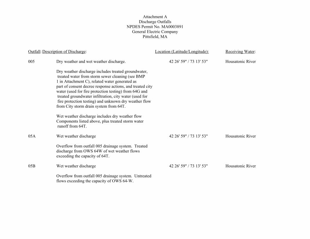
Attachment A Discharge Outfalls NPDES Permit No. MA0003891 General Electric Company
Pittsfield, MA Outfall: Description of Discharge: Location (Latitude/Longitude): Receiving Water: 005 Dry weather and wet weather discharge. 42 26' 59" / 73 13' 53" Housatonic River
Dry weather discharge includes treated groundwater, treated water from storm sewer cleaning (see BMP 1 in Attachment C), related water generated as part of consent decree response actions, and treated city water (used for fire protection testing) from 64G and treated groundwater infiltration, city water (used for fire protection testing) and unknown dry weather flow from City storm drain system from 64T. Wet weather discharge includes dry weather flow Components listed above, plus treated storm water runoff from 64T.
05A Wet weather discharge 42 26' 59" / 73 13' 53" Housatonic River
Overflow from outfall 005 drainage system. Treated discharge from OWS 64W of wet weather flows exceeding the capacity of 64T.
05B Wet weather discharge 42 26' 59" / 73 13' 53" Housatonic River
Overflow from outfall 005 drainage system. Untreated flows exceeding the capacity of OWS 64-W.

Attachment A Discharge Outfalls NPDES Permit No. MA0003891 General Electric Company
Pittsfield, MA
Outfall: Description of Discharge: Location (Latitude/Longitude): Receiving Water: 006 Dry and wet weather discharge. 42 27' 04" / 73 13' 44" Housatonic River
Dry weather flow includes discharge from OWS 64-X of groundwater infiltration, city water (used for fire protection testing) and unknown dry weather flow from city storm drain. Wet weather flow consists of discharge from OWS 64-X Including dry weather flow components listed above plus facility and city storm water runoff.
06A Wet weather discharge 42 27' 04" / 73 13 44" Housatonic River Overflow from 006 drainage area. Consists of untreated flows exceeding the capacity of OWS 64-X. SRO5 Wet weather discharge ___ Housatonic River Overflow from 006 drainage area. Consists of untreated Flows exceeding the capacity of OWS 64-X. 009 Dry weather and wet weather discharge 42 27' 42" / 73 12' 30" Unkamet Brook
Dry weather flow consists of discharge from OWS 119, including groundwater infiltration, city water (used for fire protection testing) and untreated groundwater infiltration. Wet weather flow consists of dry weather flow components listed above plus storm water. Storm water is treated in OWS 119–W to its hydraulic capacity; flows exceeding the capacity of OWS 119-W are discharged untreated.
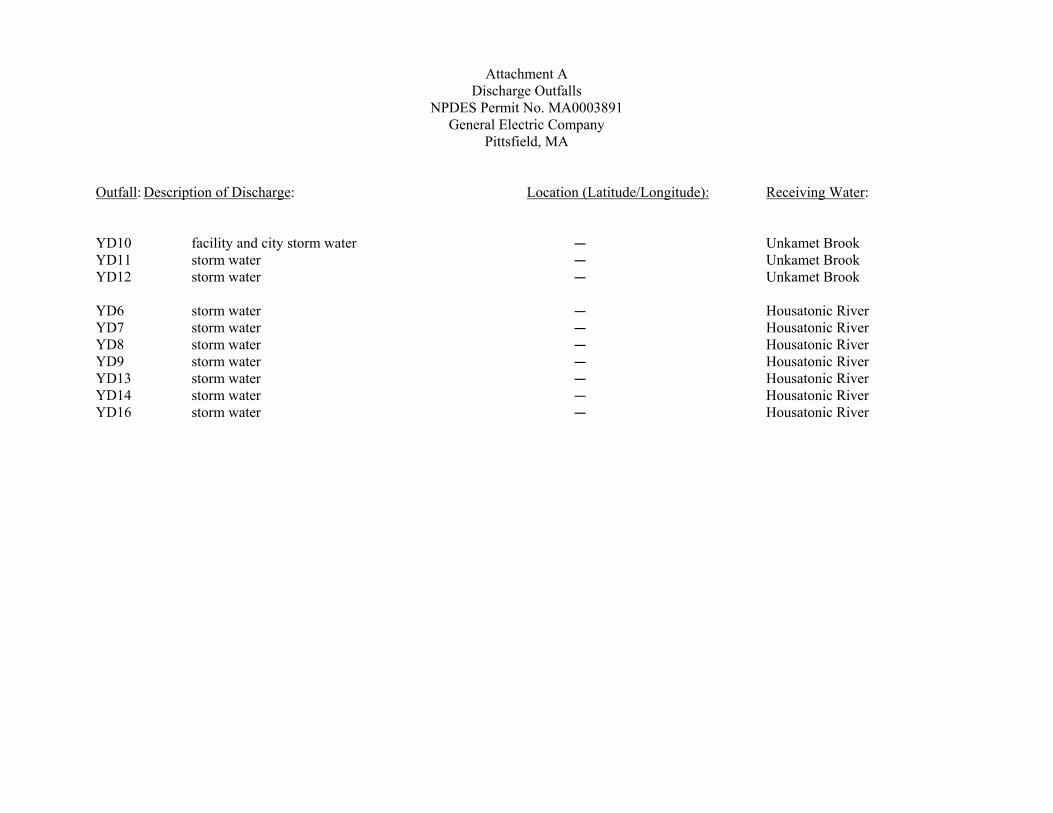
Attachment A
Discharge Outfalls NPDES Permit No. MA0003891 General Electric Company
Pittsfield, MA Outfall: Description of Discharge: Location (Latitude/Longitude): Receiving Water: YD10 facility and city storm water C Unkamet Brook YD11 storm water C Unkamet Brook YD12 storm water C Unkamet Brook YD6 storm water C Housatonic River YD7 storm water C Housatonic River YD8 storm water C Housatonic River YD9 storm water C Housatonic River YD13 storm water C Housatonic River YD14 storm water C Housatonic River YD16 storm water C Housatonic River
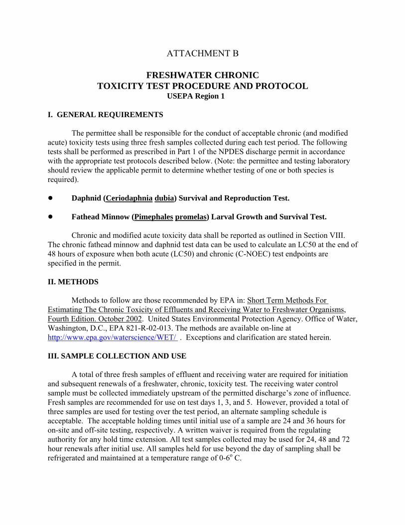
ATTACHMENT B
FRESHWATER CHRONIC TOXICITY TEST PROCEDURE AND PROTOCOL
USEPA Region 1 I. GENERAL REQUIREMENTS The permittee shall be responsible for the conduct of acceptable chronic (and modified acute) toxicity tests using three fresh samples collected during each test period. The following tests shall be performed as prescribed in Part 1 of the NPDES discharge permit in accordance with the appropriate test protocols described below. (Note: the permittee and testing laboratory should review the applicable permit to determine whether testing of one or both species is required). ! Daphnid (Ceriodaphnia dubia) Survival and Reproduction Test. ! Fathead Minnow (Pimephales promelas) Larval Growth and Survival Test. Chronic and modified acute toxicity data shall be reported as outlined in Section VIII. The chronic fathead minnow and daphnid test data can be used to calculate an LC50 at the end of 48 hours of exposure when both acute (LC50) and chronic (C-NOEC) test endpoints are specified in the permit. II. METHODS Methods to follow are those recommended by EPA in: Short Term Methods For Estimating The Chronic Toxicity of Effluents and Receiving Water to Freshwater Organisms, Fourth Edition. October 2002. United States Environmental Protection Agency. Office of Water, Washington, D.C., EPA 821-R-02-013. The methods are available on-line at http://www.epa.gov/waterscience/WET/ . Exceptions and clarification are stated herein. III. SAMPLE COLLECTION AND USE A total of three fresh samples of effluent and receiving water are required for initiation and subsequent renewals of a freshwater, chronic, toxicity test. The receiving water control sample must be collected immediately upstream of the permitted discharge’s zone of influence. Fresh samples are recommended for use on test days 1, 3, and 5. However, provided a total of three samples are used for testing over the test period, an alternate sampling schedule is acceptable. The acceptable holding times until initial use of a sample are 24 and 36 hours for on-site and off-site testing, respectively. A written waiver is required from the regulating authority for any hold time extension. All test samples collected may be used for 24, 48 and 72 hour renewals after initial use. All samples held for use beyond the day of sampling shall be refrigerated and maintained at a temperature range of 0-6o C.
All samples submitted for chemical and physical analyses will be analyzed according to Section VI of this protocol.
Sampling guidance dictates that, where appropriate, aliquots for the analysis required in this protocol shall be split from the samples, containerized and immediately preserved, or analyzed as per 40 CFR Part 136. EPA approved test methods require that samples collected for metals analyses be preserved immediately after collection. Testing for the presence of total residual chlorine (TRC) must be analyzed immediately or as soon as possible, for all effluent samples, prior to WET testing. TRC analysis may be performed on-site or by the toxicity testing laboratory and the samples must be dechlorinated, as necessary, using sodium thiosulfate prior to sample use for toxicity testing. If any of the renewal samples are of sufficient potency to cause lethality to 50 percent or more of the test organisms in any of the test treatments for either species or, if the test fails to meet its permit limits, then chemical analysis for total metals (originally required for the initial sample only in Section VI) will be required on the renewal sample(s) as well. IV. DILUTION WATER Samples of receiving water must be collected from a location in the receiving water body immediately upstream of the permitted discharge’s zone of influence at a reasonably accessible location. Avoid collection near areas of obvious road or agricultural runoff, storm sewers or other point source discharges and areas where stagnant conditions exist. EPA strongly urges that screening for toxicity be performed prior to the set up of a full, definitive toxicity test any time there is a question about the test dilution water's ability to achieve test acceptability criteria (TAC) as indicated in Section V of this protocol. The test dilution water control response will be used in the statistical analysis of the toxicity test data. All other control(s) required to be run in the test will be reported as specified in the Discharge Monitoring Report (DMR) Instructions, Attachment F, page 2,Test Results & Permit Limits. The test dilution water must be used to determine whether the test met the applicable TAC. When receiving water is used for test dilution, an additional control made up of standard laboratory water (0% effluent) is required. This control will be used to verify the health of the test organisms and evaluate to what extent, if any, the receiving water itself is responsible for any toxic response observed. If dechlorination of a sample by the toxicity testing laboratory is necessary a “sodium thiosulfate” control, representing the concentration of sodium thiosulfate used to adequately dechlorinate the sample prior to toxicity testing, must be included in the test. If the use of an alternate dilution water (ADW) is authorized, in addition to the ADW test control, the testing laboratory must, for the purpose of monitoring the receiving water, also run a receiving water control.
If the receiving water diluent is found to be, or suspected to be toxic or unreliable an
ADW of known quality with hardness similar to that of the receiving water may be substituted. Substitution is species specific meaning that the decision to use ADW is made for each species and is based on the toxic response of that particular species. Substitution to an ADW is authorized in two cases. The first is the case where repeating a test due to toxicity in the site dilution water requires an immediate decision for ADW use be made by the permittee and toxicity testing laboratory. The second is in the case where two of the most recent documented incidents of unacceptable site dilution water toxicity requires ADW use in future WET testing.
For the second case, written notification from the permittee requesting ADW use and written authorization from the permit issuing agency(s) is required prior to switching to a long-term use of ADW for the duration of the permit.
Written requests for use of ADW must be mailed with supporting documentation to the
following addresses: Director Office of Ecosystem Protection (CAA) U.S. Environmental Protection Agency-New England One Congress St., Suite 1100 Boston, MA 02114-2023 and Manager Water Technical Unit (SEW) U.S. Environmental Protection Agency One Congress Street, Suite 1100 Boston, MA 02114-2023 Note: USEPA Region 1 retains the right to modify any part of the alternate dilution water policy stated in this protocol at any time. Any changes to this policy will be documented in the annual DMR posting. See the most current annual DMR instructions which can be found on the EPA Region 1 website at http://www.epa.gov/region1/enforcementandassistance/dmr.html for further important details on alternate dilution water substitution requests. V. TEST CONDITIONS AND TEST ACCEPTABILITY CRITERIA Method specific test conditions and TAC are to be followed and adhered to as specified in the method guidance document, EPA 821-R-02-013. If a test does not meet TAC the test must be repeated with fresh samples within 30 days of the initial test completion date. V.1. Use of Reference Toxicity Testing
Reference toxicity test results and applicable control charts must be included in the toxicity testing report.
If reference toxicity test results fall outside the control limits established by the laboratory for a specific test endpoint, a reason or reasons for this excursion must be evaluated, correction made and reference toxicity tests rerun as necessary.
If a test endpoint value exceeds the control limits at a frequency of more than one out of
twenty then causes for the reference toxicity test failure must be examined and if problems are identified corrective action taken. The reference toxicity test must be repeated during the same month in which the exceedance occurred.
If two consecutive reference toxicity tests fall outside control limits, the possible cause(s) for the exceedance must be examined, corrective actions taken and a repeat of the reference toxicity test must take place immediately. Actions taken to resolve the problem must be reported. V.1.a. Use of Concurrent Reference Toxicity Testing In the case where concurrent reference toxicity testing is required due to a low frequency of testing with a particular method, if the reference toxicity test results fall slightly outside of laboratory established control limits, but the primary test met the TAC, the results of the primary test will be considered acceptable. However, if the results of the concurrent test fall well outside the established upper control limits i.e. >3 standard deviations for IC25s and LC50 values and > two concentration intervals for NOECs or NOAECs, and even though the primary test meets TAC, the primary test will be considered unacceptable and must be repeated. V.2. For the C. dubia test, the determination of TAC and formal statistical analyses must be performed using only the first three broods produced. V.3. Test treatments must include 5 effluent concentrations and a dilution water control. An additional test treatment, at the permitted effluent concentration (% effluent), is required if it is not included in the dilution series. VI. CHEMICAL ANALYSIS As part of each toxicity test’s daily renewal procedure, pH, specific conductance, dissolved oxygen (DO) and temperature must be measured at the beginning and end of each 24-hour period in each test treatment and the control(s). The additional analysis that must be performed under this protocol is as specified and noted in the table below. Parameter Effluent Receiving ML (mg/l) Water Hardness1, 4 x x 0.5 Total Residual Chlorine (TRC)2, 3, 4 x 0.02
Alkalinity4 x x 2.0 pH4 x x -- Specific Conductance4 x x -- Total Solids 6 x -- Total Dissolved Solids 6 x -- Ammonia4 x x 0.1 Total Organic Carbon 6 x x 0.5 Total Metals 5 Cd x x 0.0005 Pb x x 0.0005 Cu x x 0.003 Zn x x 0.005 Ni x x 0.005 Al x x 0.02 Other as permit requires Notes: 1. Hardness may be determined by:
• APHA Standard Methods for the Examination of Water and Wastewater , 21st Edition -Method 2340B (hardness by calculation)
-Method 2340C (titration) 2. Total Residual Chlorine may be performed using any of the following methods provided the required minimum limit (ML) is met.
• APHA Standard Methods for the Examination of Water and Wastewater , 21st Edition -Method 4500-CL E Low Level Amperometric Titration
-Method 4500-CL G DPD Colorimetric Method • USEPA 1983. Manual of Methods Analysis of Water and Wastes
-Method 330.5 3. Required to be performed on the sample used for WET testing prior to its use for toxicity testing 4. Analysis is to be performed on samples and/or receiving water, as designated in the table above, from all three sampling events.
5. Analysis is to be performed on the initial sample(s) only unless the situation arises as stated in Section III, paragraph 4 6. Analysis to be performed on initial samples only VII. TOXICITY TEST DATA ANALYSIS AND REVIEW A. Test Review 1. Concentration / Response Relationship A concentration/response relationship evaluation is required for test endpoint determinations from both Hypothesis Testing and Point Estimate techniques. The test report is to include documentation of this evaluation in support of the endpoint values reported. The dose-response review must be performed as required in Section 10.2.6 of EPA-821-R-02-013. Guidance for this review can be found at http://www.epa.gov/waterscience/WET/guide/index.html . In most cases, the review will result in one of the following three conclusions: (1) Results are reliable and reportable; (2) Results are
anomalous and require explanation; or (3) Results are inconclusive and a retest with fresh samples is required. 2. Test Variability (Test Sensitivity) This review step is separate from the determination of whether a test meets or does not meet TAC. Within test variability is to be examined for the purpose of evaluating test sensitivity. This evaluation is to be performed for the sub-lethal hypothesis testing endpoints reproduction and growth as required by the permit. The test report is to include documentation of this evaluation to support that the endpoint values reported resulted from a toxicity test of adequate sensitivity. This evaluation must be performed as required in Section 10.2.8 of EPA-821-R-02-013. To determine the adequacy of test sensitivity, USEPA requires the calculation of test percent minimum significant difference (PMSD) values. In cases where NOEC determinations are made based on a non-parametric technique, calculation of a test PMSD value, for the sole purpose of assessing test sensitivity, shall be calculated using a comparable parametric statistical analysis technique. The calculated test PMSD is then compared to the upper and lower PMSD bounds shown for freshwater tests in Section 10.2.8.3, p. 52, Table 6 of EPA-821-R-02-013. The comparison will yield one of the following determinations. • The test PMSD exceeds the PMSD upper bound test variability criterion in Table 6, the test
results are considered highly variable and the test may not be sensitive enough to determine the presence of toxicity at the permit limit concentration (PLC). If the test results indicate that the discharge is not toxic at the PLC, then the test is considered insufficiently sensitive and must be repeated within 30 days of the initial test completion using fresh samples. If the test results indicate that the discharge is toxic at the PLC, the test is considered acceptable and does not have to be repeated.
• The test PMSD falls below the PMSD lower bound test variability criterion in Table 6, the test is
determined to be very sensitive. In order to determine which treatment(s) are statistically significant and which are not, for the purpose of reporting a NOEC, the relative percent difference (RPD) between the control and each treatment must be calculated and compared to the lower PMSD boundary. See Understanding and Accounting for Method Variability in Whole Effluent Toxicity Applications Under the NPDES Program, EPA 833-R-00-003, June 2002, Section 6.4.2. The following link: Understanding and Accounting for Method Variability in Whole Effluent Toxicity Applications Under the NPDES Program can be used to locate the USEPA website containing this document. If the RPD for a treatment falls below the PMSD lower bound, the difference is considered statistically insignificant. If the RPD for a treatment is greater that the PMSD lower bound, then the treatment is considered statistically significant.
• The test PMSD falls within the PMSD upper and lower bounds in Table 6, the sub-lethal test
endpoint values shall be reported as is.

B. Statistical Analysis 1. General - Recommended Statistical Analysis Method Refer to general data analysis flowchart, EPA 821-R-02-013, page 43 For discussion on Hypothesis Testing, refer to EPA 821-R-02-013, Section 9.6
For discussion on Point Estimation Techniques, refer to EPA 821-R-02-013, Section 9.7
2. Pimephales promelas
Refer to survival hypothesis testing analysis flowchart, EPA 821-R-02-013, page 79
Refer to survival point estimate techniques flowchart, EPA 821-R-02-013, page 80 Refer to growth data statistical analysis flowchart, EPA 821-R-02-013, page 92 3. Ceriodaphnia dubia
Refer to survival data testing flowchart, EPA 821-R-02-013, page 168
Refer to reproduction data testing flowchart, EPA 821-R-02-013, page 173 VIII. TOXICITY TEST REPORTING A report of results must include the following:
• Test summary sheets (2007 DMR Attachment F) which includes: o Facility name o NPDES permit number o Outfall number o Sample type o Sampling method o Effluent TRC concentration o Dilution water used o Receiving water name and sampling location o Test type and species o Test start date o Effluent concentrations tested (%) and permit limit concentration o Applicable reference toxicity test date and whether acceptable or not o Age, age range and source of test organisms used for testing o Results of TAC review for all applicable controls o Test sensitivity evaluation results (test PMSD for growth and reproduction) o Permit limit and toxicity test results
o Summary of test sensitivity and concentration response evaluation
In addition to the summary sheets the report must include:
• A brief description of sample collection procedures • Chain of custody documentation including names of individuals collecting samples, times
and dates of sample collection, sample locations, requested analysis and lab receipt with time and date received, lab receipt personnel and condition of samples upon receipt at the lab(s)
• Reference toxicity test control charts • All sample chemical/physical data generated, including minimum limits (MLs) and
analytical methods used • All toxicity test raw data including daily ambient test conditions, toxicity test chemistry,
sample dechlorination details as necessary, bench sheets and statistical analysis • A discussion of any deviations from test conditions • Any further discussion of reported test results, statistical analysis and concentration-
response relationship and test sensitivity review per species per endpoint
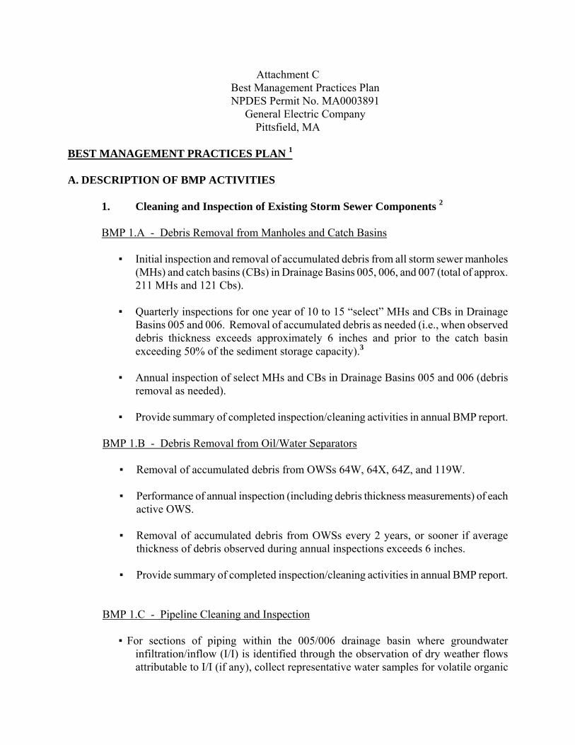
Attachment C Best Management Practices Plan NPDES Permit No. MA0003891 General Electric Company
Pittsfield, MA BEST MANAGEMENT PRACTICES PLAN 1 A. DESCRIPTION OF BMP ACTIVITIES
1. Cleaning and Inspection of Existing Storm Sewer Components 2
BMP 1.A - Debris Removal from Manholes and Catch Basins
▪ Initial inspection and removal of accumulated debris from all storm sewer manholes (MHs) and catch basins (CBs) in Drainage Basins 005, 006, and 007 (total of approx. 211 MHs and 121 Cbs).
▪ Quarterly inspections for one year of 10 to 15 “select” MHs and CBs in Drainage
Basins 005 and 006. Removal of accumulated debris as needed (i.e., when observed debris thickness exceeds approximately 6 inches and prior to the catch basin exceeding 50% of the sediment storage capacity).3
▪ Annual inspection of select MHs and CBs in Drainage Basins 005 and 006 (debris
removal as needed).
▪ Provide summary of completed inspection/cleaning activities in annual BMP report.
BMP 1.B - Debris Removal from Oil/Water Separators
▪ Removal of accumulated debris from OWSs 64W, 64X, 64Z, and 119W. ▪ Performance of annual inspection (including debris thickness measurements) of each
active OWS.
▪ Removal of accumulated debris from OWSs every 2 years, or sooner if average thickness of debris observed during annual inspections exceeds 6 inches.
▪ Provide summary of completed inspection/cleaning activities in annual BMP report.
BMP 1.C - Pipeline Cleaning and Inspection
▪ For sections of piping within the 005/006 drainage basin where groundwater infiltration/inflow (I/I) is identified through the observation of dry weather flows attributable to I/I (if any), collect representative water samples for volatile organic
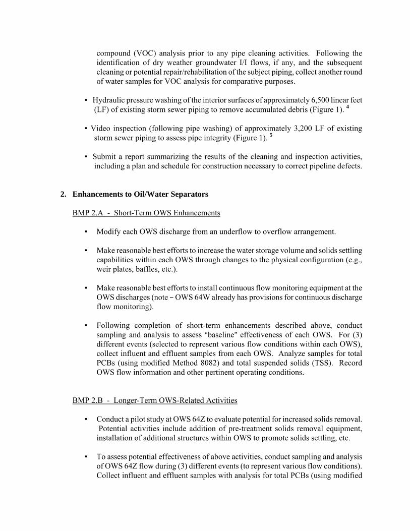
compound (VOC) analysis prior to any pipe cleaning activities. Following the identification of dry weather groundwater I/I flows, if any, and the subsequent cleaning or potential repair/rehabilitation of the subject piping, collect another round of water samples for VOC analysis for comparative purposes.
▪ Hydraulic pressure washing of the interior surfaces of approximately 6,500 linear feet
(LF) of existing storm sewer piping to remove accumulated debris (Figure 1). 4 ▪ Video inspection (following pipe washing) of approximately 3,200 LF of existing
storm sewer piping to assess pipe integrity (Figure 1). 5
▪ Submit a report summarizing the results of the cleaning and inspection activities, including a plan and schedule for construction necessary to correct pipeline defects.
2. Enhancements to Oil/Water Separators
BMP 2.A - Short-Term OWS Enhancements
▪ Modify each OWS discharge from an underflow to overflow arrangement. ▪ Make reasonable best efforts to increase the water storage volume and solids settling
capabilities within each OWS through changes to the physical configuration (e.g., weir plates, baffles, etc.).
▪ Make reasonable best efforts to install continuous flow monitoring equipment at the
OWS discharges (note B OWS 64W already has provisions for continuous discharge flow monitoring).
▪ Following completion of short-term enhancements described above, conduct
sampling and analysis to assess Abaseline@ effectiveness of each OWS. For (3) different events (selected to represent various flow conditions within each OWS), collect influent and effluent samples from each OWS. Analyze samples for total PCBs (using modified Method 8082) and total suspended solids (TSS). Record OWS flow information and other pertinent operating conditions.
BMP 2.B - Longer-Term OWS-Related Activities
▪ Conduct a pilot study at OWS 64Z to evaluate potential for increased solids removal.
Potential activities include addition of pre-treatment solids removal equipment, installation of additional structures within OWS to promote solids settling, etc.
▪ To assess potential effectiveness of above activities, conduct sampling and analysis
of OWS 64Z flow during (3) different events (to represent various flow conditions). Collect influent and effluent samples with analysis for total PCBs (using modified
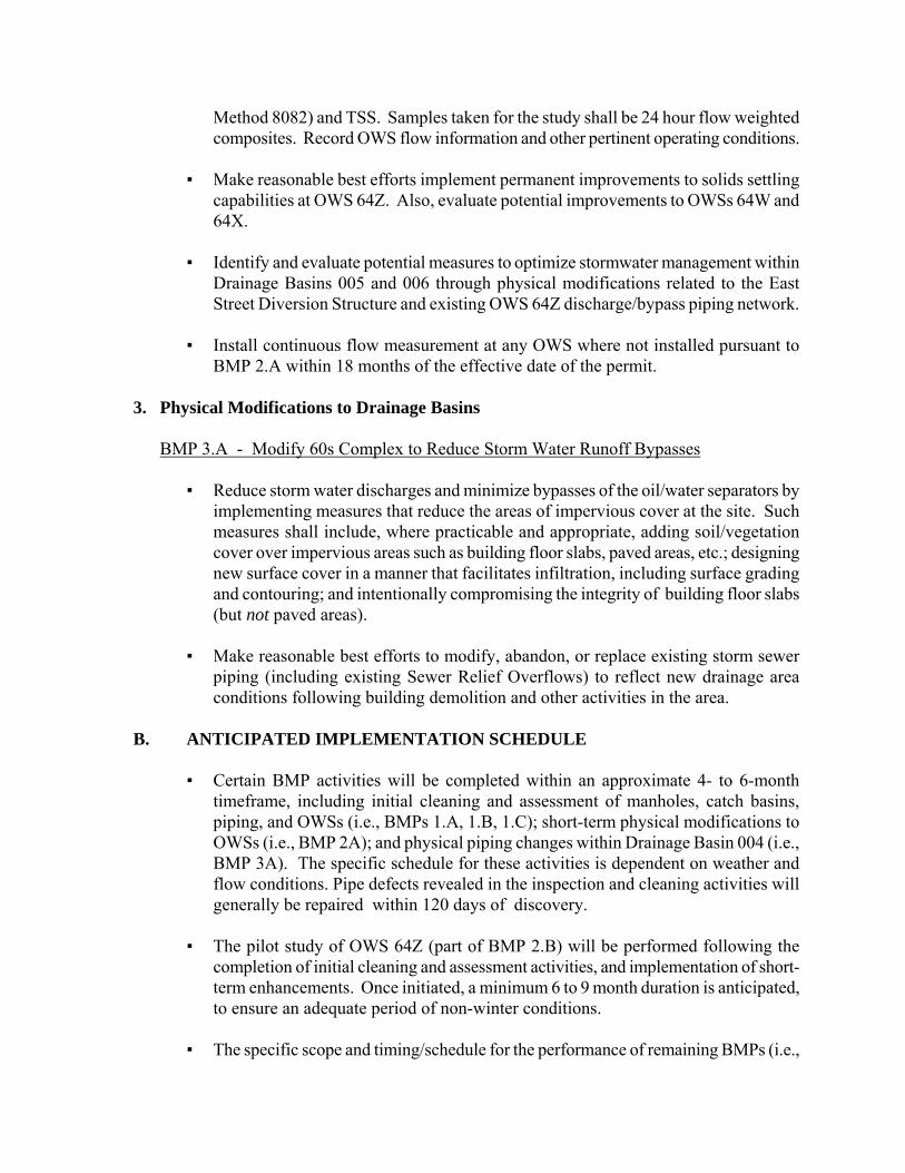
Method 8082) and TSS. Samples taken for the study shall be 24 hour flow weighted composites. Record OWS flow information and other pertinent operating conditions.
▪ Make reasonable best efforts implement permanent improvements to solids settling
capabilities at OWS 64Z. Also, evaluate potential improvements to OWSs 64W and 64X.
▪ Identify and evaluate potential measures to optimize stormwater management within
Drainage Basins 005 and 006 through physical modifications related to the East Street Diversion Structure and existing OWS 64Z discharge/bypass piping network.
▪ Install continuous flow measurement at any OWS where not installed pursuant to
BMP 2.A within 18 months of the effective date of the permit.
3. Physical Modifications to Drainage Basins
BMP 3.A - Modify 60s Complex to Reduce Storm Water Runoff Bypasses ▪ Reduce storm water discharges and minimize bypasses of the oil/water separators by
implementing measures that reduce the areas of impervious cover at the site. Such measures shall include, where practicable and appropriate, adding soil/vegetation cover over impervious areas such as building floor slabs, paved areas, etc.; designing new surface cover in a manner that facilitates infiltration, including surface grading and contouring; and intentionally compromising the integrity of building floor slabs (but not paved areas).
▪ Make reasonable best efforts to modify, abandon, or replace existing storm sewer
piping (including existing Sewer Relief Overflows) to reflect new drainage area conditions following building demolition and other activities in the area.
B. ANTICIPATED IMPLEMENTATION SCHEDULE
▪ Certain BMP activities will be completed within an approximate 4- to 6-month
timeframe, including initial cleaning and assessment of manholes, catch basins, piping, and OWSs (i.e., BMPs 1.A, 1.B, 1.C); short-term physical modifications to OWSs (i.e., BMP 2A); and physical piping changes within Drainage Basin 004 (i.e., BMP 3A). The specific schedule for these activities is dependent on weather and flow conditions. Pipe defects revealed in the inspection and cleaning activities will generally be repaired within 120 days of discovery.
▪ The pilot study of OWS 64Z (part of BMP 2.B) will be performed following the
completion of initial cleaning and assessment activities, and implementation of short-term enhancements. Once initiated, a minimum 6 to 9 month duration is anticipated, to ensure an adequate period of non-winter conditions.
▪ The specific scope and timing/schedule for the performance of remaining BMPs (i.e.,
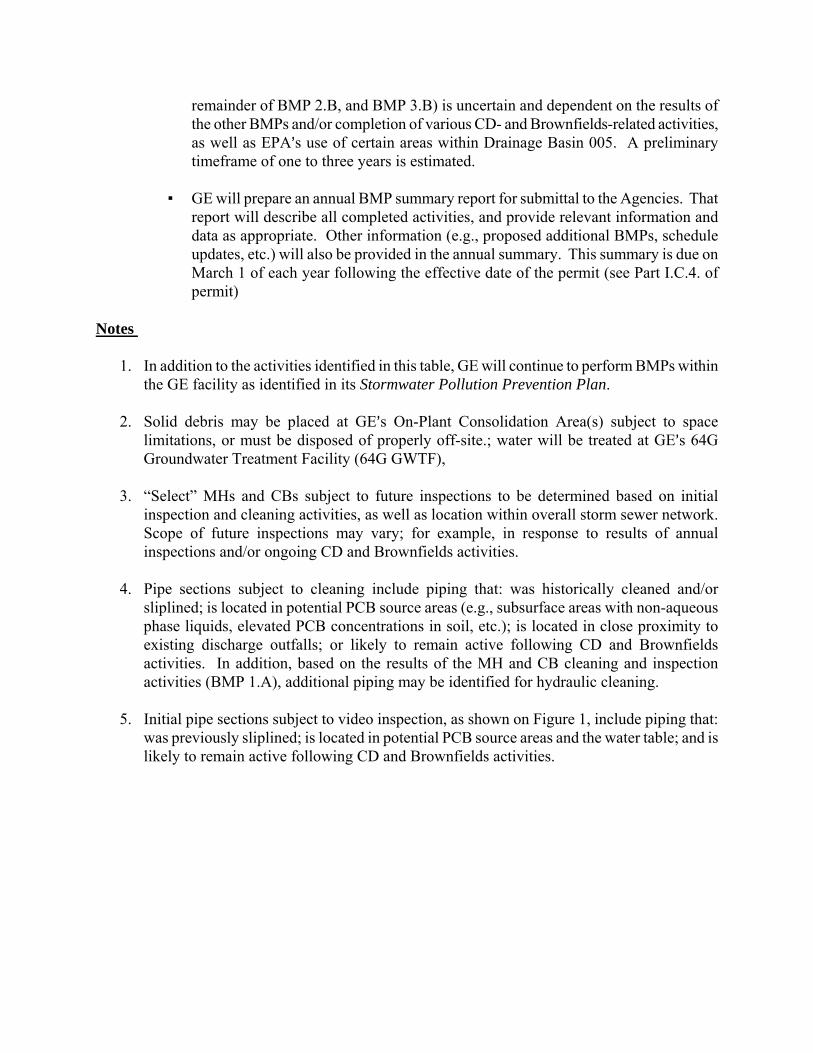
remainder of BMP 2.B, and BMP 3.B) is uncertain and dependent on the results of the other BMPs and/or completion of various CD- and Brownfields-related activities, as well as EPA=s use of certain areas within Drainage Basin 005. A preliminary timeframe of one to three years is estimated.
▪ GE will prepare an annual BMP summary report for submittal to the Agencies. That
report will describe all completed activities, and provide relevant information and data as appropriate. Other information (e.g., proposed additional BMPs, schedule updates, etc.) will also be provided in the annual summary. This summary is due on March 1 of each year following the effective date of the permit (see Part I.C.4. of permit)
Notes
1. In addition to the activities identified in this table, GE will continue to perform BMPs within the GE facility as identified in its Stormwater Pollution Prevention Plan.
2. Solid debris may be placed at GE=s On-Plant Consolidation Area(s) subject to space
limitations, or must be disposed of properly off-site.; water will be treated at GE=s 64G Groundwater Treatment Facility (64G GWTF),
3. “Select” MHs and CBs subject to future inspections to be determined based on initial
inspection and cleaning activities, as well as location within overall storm sewer network. Scope of future inspections may vary; for example, in response to results of annual inspections and/or ongoing CD and Brownfields activities.
4. Pipe sections subject to cleaning include piping that: was historically cleaned and/or
sliplined; is located in potential PCB source areas (e.g., subsurface areas with non-aqueous phase liquids, elevated PCB concentrations in soil, etc.); is located in close proximity to existing discharge outfalls; or likely to remain active following CD and Brownfields activities. In addition, based on the results of the MH and CB cleaning and inspection activities (BMP 1.A), additional piping may be identified for hydraulic cleaning.
5. Initial pipe sections subject to video inspection, as shown on Figure 1, include piping that:
was previously sliplined; is located in potential PCB source areas and the water table; and is likely to remain active following CD and Brownfields activities.

ATTACHMENT D
PCB Method Specification
Justification and Approval for Using SW-846 Method 8082 in Place of CWA Method 608
The Federal Water Pollution Control Act, as amended by the Clean Water Act of 1977, requires that specific analytical methods be used to generate reports required for each discharge regulated under the National Pollutant Discharge Elimination System (NPDES). These methods are listed in 40 CFR Part 136.3. Paragraph (a) provides that under certain circumstances other Amore advantageous@ test procedures may be used when such procedures have been approved by the Regional Administrator, providing the Director of the State in which the discharge is located does not object. 40 CFR 136.3(c) authorizes the Regional Administrator to approve the use of methods of analysis for additional pollutants or parameters. Under this provision, the Regional Administrator has the authority to require the use of alternate procedures when an approved method is unable to achieve the practical quantitation limit (PQL) required by the permit and an alternate method is able to achieve it. PCB methods are listed in Table IC, AList of Approved Test Procedures for Non-Pesticide Organic Compounds@. Method 608, found in 40 CFR 136 Appendix A, is a gas chromatographic (GC) procedure which utilizes electron capture detection (ECD). It has a practical quantitation limit (PQL) of 0.5Fg/L. It is a prescriptive method and does not permit modifications to achieve lower PQLs, such as the use of alternate sample extract clean-up procedures to improve GC/ECD chromatography and peak resolution in the presence of interferences. It was used for many years as the only method for the analysis of PCBs in wastewater. However, many contract laboratories no longer use it because improved methods are available. Method 608 was used as a model for methods 8080 and 8081, the original RCRA SW-846 methods for PCBs and pesticides. Method 8082, APolychorinated Biphenyls by Gas chromatography,@ is found in Test Methods for Evaluating Solid Waste, Physical/Chemical Methods, SW-846. SW-846 methods are performance based methods that allow method modifications to improve chromatography and sensitivity, including the extraction of larger sample volumes, the concentration of sample extracts to smaller volumes, and the injection of larger volumes of sample extracts.. Such modifications permit much lower PQLs to be achieved. Method 8082 can be modified to meet a 0.065 Fg/L total PCB reporting limit that will support the GE Housatonic River NPDES permit. It may also be modified to allow identification and quantitation of individual PCB congeners at much lower detection limits (e.g., 0.014Fg/L) when required. Because method 8082 is performance based, each laboratory is required to demonstrate that any modifications to the published method are substantiated by acceptable, documented quality control criteria (e.g., MDL determinations), that method performance is controlled and consistent from sample to sample, lot to lot, and day to day operations and that the modifications serve the requirements of the permit. EPA has reviewed various standards operating procedures (SOPs) that General Electric - Pittsfield submitted for the analysis of PCBs, including SOPs received on May 27, 2008:
SGS Environmental Services SOP for the Analysis of Low level PCBs by modified Method 8082, ID # 8082, Date 02/01/08 SGS Environmental Services SOP for Modified Method 3520 for low level PCB Preparation in Water, ID # 3520 Water Prep., Date 02/01/08
Note: method 3520 is a sample preparation procedure used to prepare samples for analysis by method 8082. With the receipt of certain supplemental information from General Electric, EPA has received satisfactory answers to all its review questions. GE's use of the submitted SGS SOPs, including the two mentioned above, for the analysis of PCB Aroclors is approved.
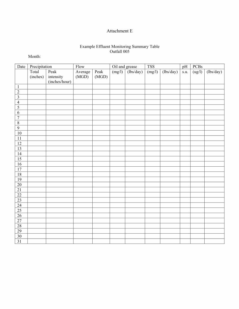
Attachment E
Example Effluent Monitoring Summary Table Outfall 005
Month:
Date Precipitation Flow Oil and grease TSS pH PCBs Total
(inches) Peak intensity (inches/hour)
Average (MGD)
Peak (MGD)
(mg/l) (lbs/day) (mg/l) (lbs/day) s.u. (ug/l) (lbs/day)
1 2 3 4 5 6 7 8 9 10 11 12 13 14 15 16 17 18 19 20 21 22 23 24 25 26 27 28 29 30 31
Appendix B
Site Drainage Plans
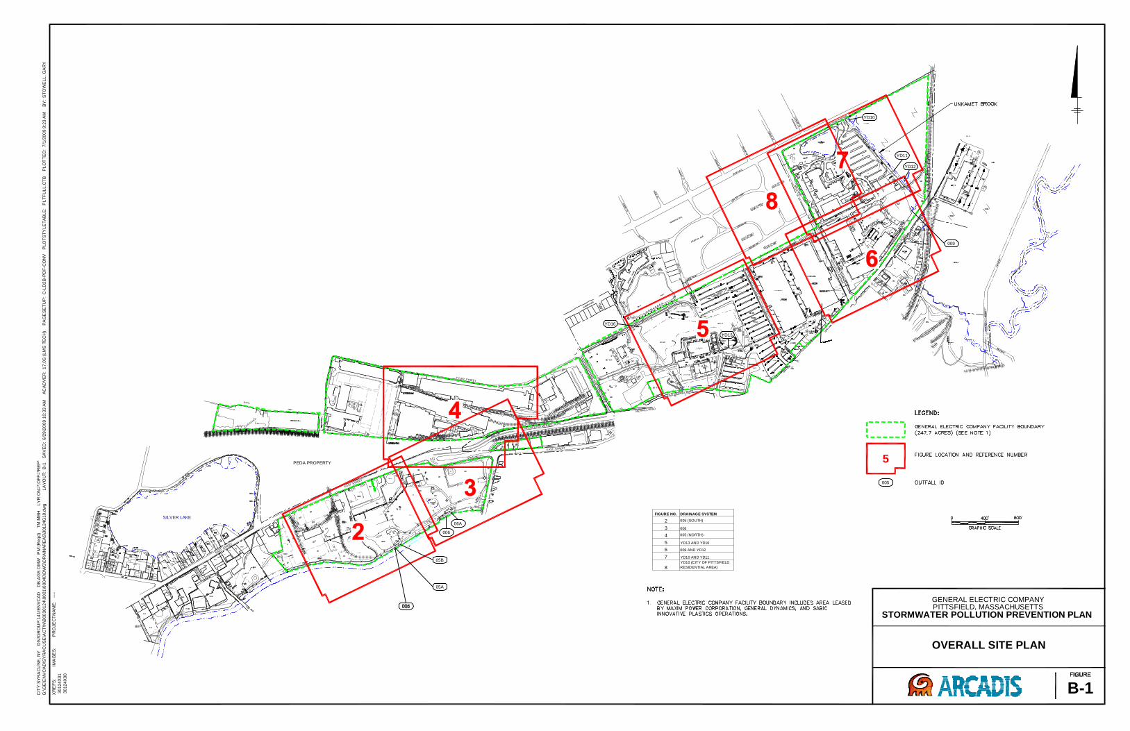
009
05A
05B
006
06A
5
005
SILVER LAKE
EASTSTREET
EAST STREET
EASTBRANCH
HOUSATONI C
RIVER
RELOCATED MERRILL ROAD
EAST STREET
NE
WY
OR
KA
VE
NU
E
MERRILL ROAD
OLD MERRILL ROAD
DALTONAVENUE
PLA
ST
ICS
AV
EN
UE
ME
RR
ILL
RO
AD
YD16
YD10
YD11
YD12
YD13
PEDA PROPERTY
TYLER STREET
FIGURE NO. DRAINAGE SYSTEM
2 005 (SOUTH)
3 006
4 005 (NORTH)
5 YD13 AND YD16
6 009 AND YD12
7 YD10 AND YD11
8YD10 (CITY OF PITTSFIELD
RESIDENTIAL AREA)
CIT
Y:S
YR
AC
US
E,N
YD
IV/G
RO
UP
:14
1/E
NV
CA
DD
B:A
GS
DM
WP
M:(
Req
d)
TM
:MB
HLY
R:O
N=*;
OF
F=*R
EF
*
G:\G
E\E
NV
CA
D\S
YR
AC
US
E\A
CT
\N\B
00
30
12
4\0
001
\000
40
\DW
G\D
RA
INA
RE
AS
\30124G
10.d
wg
LA
YO
UT
:B
-1S
AV
ED
:6
/29
/20
09
10:3
3A
MA
CA
DV
ER
:1
7.0
S(L
MS
TE
CH
)P
AG
ES
ET
UP
:C
-LD
2B
-PD
F-C
ON
VP
LO
TS
TY
LE
TA
BLE
:P
LT
FU
LL
.CT
BP
LO
TT
ED
:7
/1/2
00
99
:23
AM
BY
:S
TO
WE
LL
,G
AR
Y
OVERALL SITE PLAN
GENERAL ELECTRIC COMPANYPITTSFIELD, MASSACHUSETTS
STORMWATER POLLUTION PREVENTION PLAN
B-1
IMA
GE
S:
XR
EF
S:
30124X
01
30124X
00
PR
OJE
CT
NA
ME
:--
--
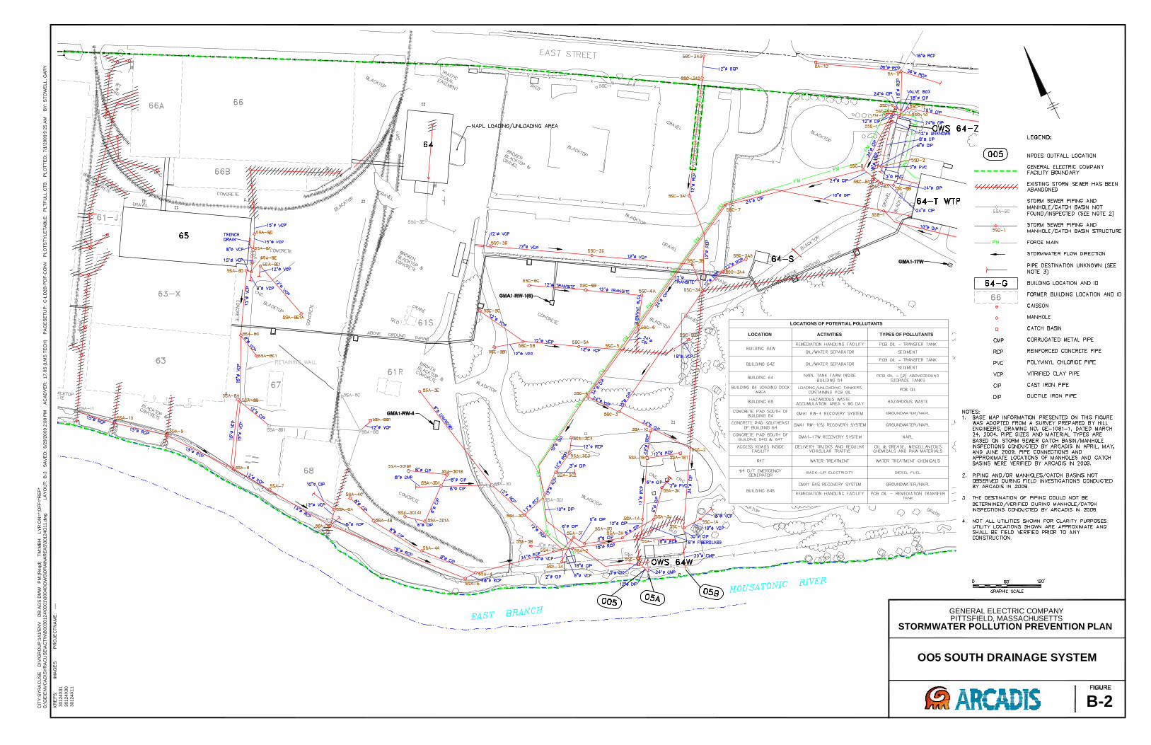
CIT
Y:S
YR
AC
US
ED
IV/G
RO
UP
:14
1/E
NV
DB
:AG
SD
MW
PM
:(R
eqd
)T
M:M
BH
LY
R:O
N=
*;O
FF
=*R
EF
*
G:\G
E\E
NV
CA
D\S
YR
AC
US
E\A
CT
\N\B
00
30
12
4\0
001
\000
40
\DW
G\D
RA
INA
RE
AS
\30124G
11.d
wg
LA
YO
UT
:B
-2S
AV
ED
:6
/29
/20
09
2:0
8P
MA
CA
DV
ER
:1
7.0
S(L
MS
TE
CH
)P
AG
ES
ET
UP
:C
-LD
2B
-PD
F-C
ON
VP
LO
TS
TY
LE
TA
BLE
:P
LT
FU
LL
.CT
BP
LO
TT
ED
:7
/1/2
00
99
:25
AM
BY
:S
TO
WE
LL
,G
AR
Y
OO5 SOUTH DRAINAGE SYSTEM
GENERAL ELECTRIC COMPANYPITTSFIELD, MASSACHUSETTS
STORMWATER POLLUTION PREVENTION PLAN
B-2
IMA
GE
S:
XR
EF
S:
30124X
01
30124X
00
30124X
11
PR
OJE
CT
NA
ME
:--
--
LOCATIONS OF POTENTIAL POLLUTANTS
LOCATION ACTIVITIES TYPES OF POLLUTANTS
–
–
–
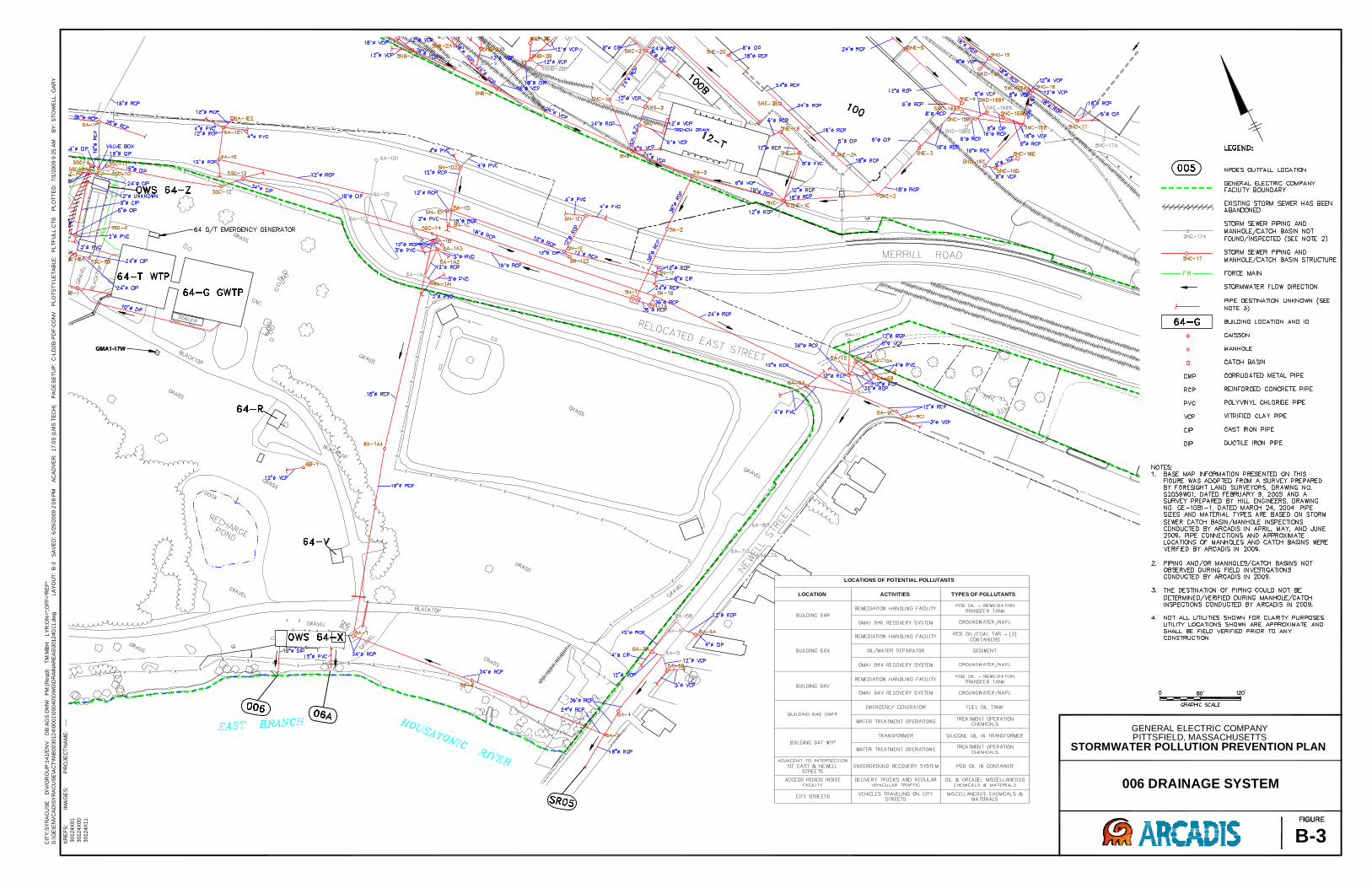
CIT
Y:S
YR
AC
US
ED
IV/G
RO
UP
:14
1/E
NV
DB
:AG
SD
MW
PM
:(R
eqd
)T
M:M
BH
LY
R:O
N=
*;O
FF
=*R
EF
*
G:\G
E\E
NV
CA
D\S
YR
AC
US
E\A
CT
\N\B
00
30
12
4\0
001
\000
40
\DW
G\D
RA
INA
RE
AS
\30124G
11.d
wg
LA
YO
UT
:B
-3S
AV
ED
:6
/29
/20
09
2:0
8P
MA
CA
DV
ER
:1
7.0
S(L
MS
TE
CH
)P
AG
ES
ET
UP
:C
-LD
2B
-PD
F-C
ON
VP
LO
TS
TY
LE
TA
BLE
:P
LT
FU
LL
.CT
BP
LO
TT
ED
:7
/1/2
00
99
:25
AM
BY
:S
TO
WE
LL
,G
AR
Y
006 DRAINAGE SYSTEM
GENERAL ELECTRIC COMPANYPITTSFIELD, MASSACHUSETTS
STORMWATER POLLUTION PREVENTION PLAN
B-3
IMA
GE
S:
XR
EF
S:
30124X
01
30124X
00
30124X
11
PR
OJE
CT
NA
ME
:--
--
LOCATIONS OF POTENTIAL POLLUTANTS
LOCATION ACTIVITIES TYPES OF POLLUTANTS
–
–
–
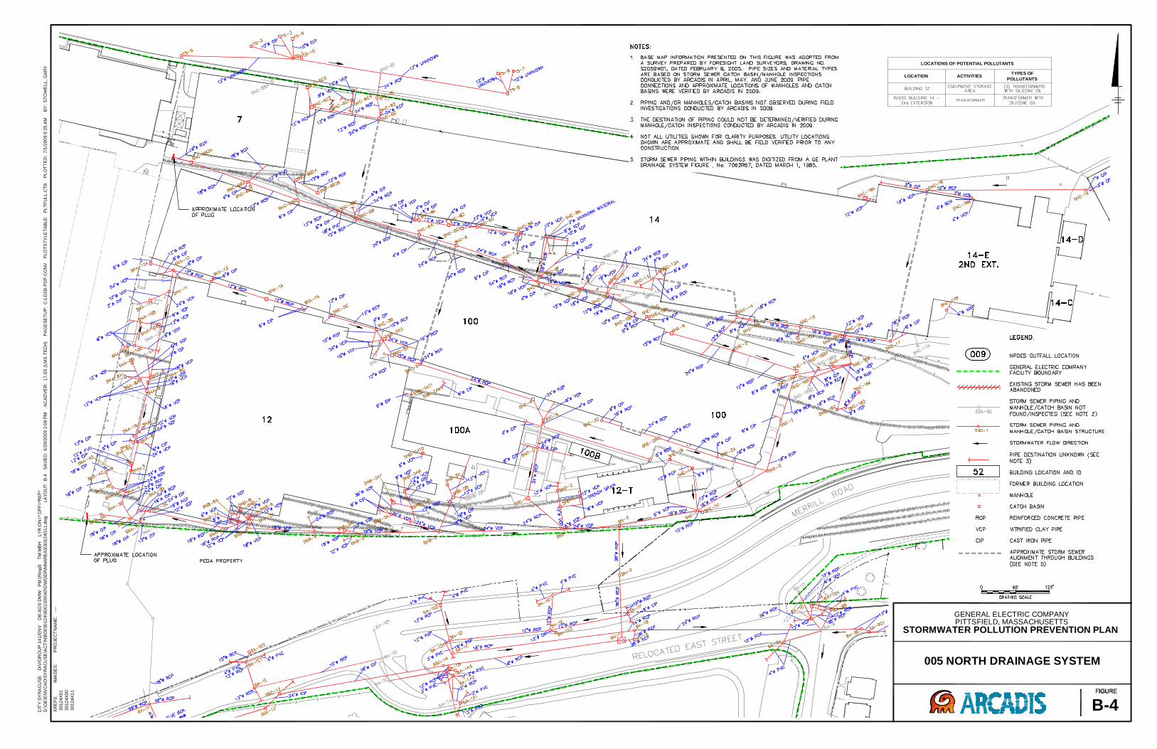
CIT
Y:S
YR
AC
US
ED
IV/G
RO
UP
:14
1/E
NV
DB
:AG
SD
MW
PM
:(R
eqd
)T
M:M
BH
LY
R:O
N=
*;O
FF
=*R
EF
*
G:\G
E\E
NV
CA
D\S
YR
AC
US
E\A
CT
\N\B
00
30
12
4\0
001
\000
40
\DW
G\D
RA
INA
RE
AS
\30124G
11.d
wg
LA
YO
UT
:B
-4S
AV
ED
:6
/29
/20
09
2:0
8P
MA
CA
DV
ER
:1
7.0
S(L
MS
TE
CH
)P
AG
ES
ET
UP
:C
-LD
2B
-PD
F-C
ON
VP
LO
TS
TY
LE
TA
BLE
:P
LT
FU
LL
.CT
BP
LO
TT
ED
:7
/1/2
00
99
:25
AM
BY
:S
TO
WE
LL
,G
AR
Y
005 NORTH DRAINAGE SYSTEM
GENERAL ELECTRIC COMPANYPITTSFIELD, MASSACHUSETTS
STORMWATER POLLUTION PREVENTION PLAN
B-4
IMA
GE
S:
XR
EF
S:
30124X
01
30124X
00
30124X
11
PR
OJE
CT
NA
ME
:--
--
LOCATIONS OF POTENTIAL POLLUTANTS
LOCATION ACTIVITIESTYPES OF
POLLUTANTS
–
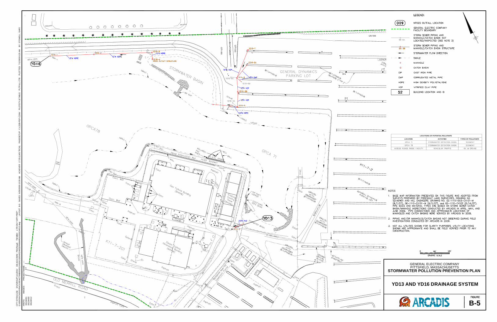
CIT
Y:S
YR
AC
US
ED
IV/G
RO
UP
:14
1/E
NV
DB
:AG
SD
MW
PM
:(R
eqd
)T
M:M
BH
LY
R:O
N=
*;O
FF
=*R
EF
*
G:\G
E\E
NV
CA
D\S
YR
AC
US
E\A
CT
\N\B
00
30
12
4\0
001
\000
40
\DW
G\D
RA
INA
RE
AS
\30124G
12.d
wg
LA
YO
UT
:B
-5S
AV
ED
:6
/29
/20
09
10:3
0A
MA
CA
DV
ER
:1
7.0
S(L
MS
TE
CH
)P
AG
ES
ET
UP
:C
-LD
2B
-PD
F-C
ON
VP
LO
TS
TY
LE
TA
BLE
:P
LT
FU
LL
.CT
BP
LO
TT
ED
:7
/1/2
00
99
:25
AM
BY
:S
TO
WE
LL
,G
AR
Y
YD13 AND YD16 DRAINAGE SYSTEM
GENERAL ELECTRIC COMPANYPITTSFIELD, MASSACHUSETTS
STORMWATER POLLUTION PREVENTION PLAN
B-5
IMA
GE
S:
XR
EF
S:
30124X
01
30124X
00
30124X
12
PR
OJE
CT
NA
ME
:--
--
LOCATIONS OF POTENTIAL POLLUTANTS
LOCATION ACTIVITIES TYPES OF POLLUTANTS
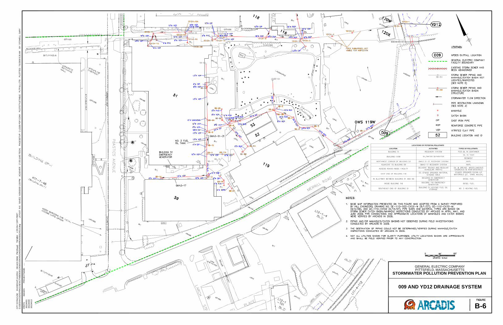
CIT
Y:S
YR
AC
US
ED
IV/G
RO
UP
:14
1/E
NV
DB
:AG
SD
MW
PM
:(R
eqd
)T
M:M
BH
LY
R:O
N=
*;O
FF
=*R
EF
*
G:\G
E\E
NV
CA
D\S
YR
AC
US
E\A
CT
\N\B
00
30
12
4\0
001
\000
40
\DW
G\D
RA
INA
RE
AS
\30124G
13.d
wg
LA
YO
UT
:B
-6S
AV
ED
:6
/29
/20
09
1:0
9P
MA
CA
DV
ER
:1
7.0
S(L
MS
TE
CH
)P
AG
ES
ET
UP
:C
-LD
2B
-PD
F-C
ON
VP
LO
TS
TY
LE
TA
BLE
:P
LT
FU
LL
.CT
BP
LO
TT
ED
:7
/1/2
00
99
:26
AM
BY
:S
TO
WE
LL
,G
AR
Y
009 AND YD12 DRAINAGE SYSTEM
GENERAL ELECTRIC COMPANYPITTSFIELD, MASSACHUSETTS
STORMWATER POLLUTION PREVENTION PLAN
B-6
IMA
GE
S:
XR
EF
S:
30124X
01
30124X
00
30124X
13
PR
OJE
CT
NA
ME
:--
--
LOCATIONS OF POTENTIAL POLLUTANTS
LOCATION ACTIVITIES TYPES OF POLLUTANTS
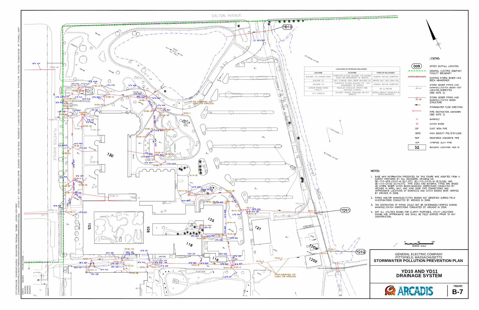
CIT
Y:S
YR
AC
US
ED
IV/G
RO
UP
:14
1/E
NV
DB
:AG
SD
MW
PM
:(R
eqd
)T
M:M
BH
LY
R:O
N=
*;O
FF
=*R
EF
*
G:\G
E\E
NV
CA
D\S
YR
AC
US
E\A
CT
\N\B
00
30
12
4\0
001
\000
40
\DW
G\D
RA
INA
RE
AS
\30124G
13.d
wg
LA
YO
UT
:B
-7S
AV
ED
:6
/29
/20
09
1:0
9P
MA
CA
DV
ER
:1
7.0
S(L
MS
TE
CH
)P
AG
ES
ET
UP
:C
-LD
2B
-PD
F-C
ON
VP
LO
TS
TY
LE
TA
BLE
:P
LT
FU
LL
.CT
BP
LO
TT
ED
:7
/1/2
00
99
:26
AM
BY
:S
TO
WE
LL
,G
AR
Y
YD10 AND YD11DRAINAGE SYSTEM
GENERAL ELECTRIC COMPANYPITTSFIELD, MASSACHUSETTS
STORMWATER POLLUTION PREVENTION PLAN
B-7
IMA
GE
S:
XR
EF
S:
30124X
01
30124X
00
30124X
13
PR
OJE
CT
NA
ME
:--
--
LOCATIONS OF POTENTIAL POLLUTANTS
LOCATION ACTIVITIES TYPES OF POLLUTANTS
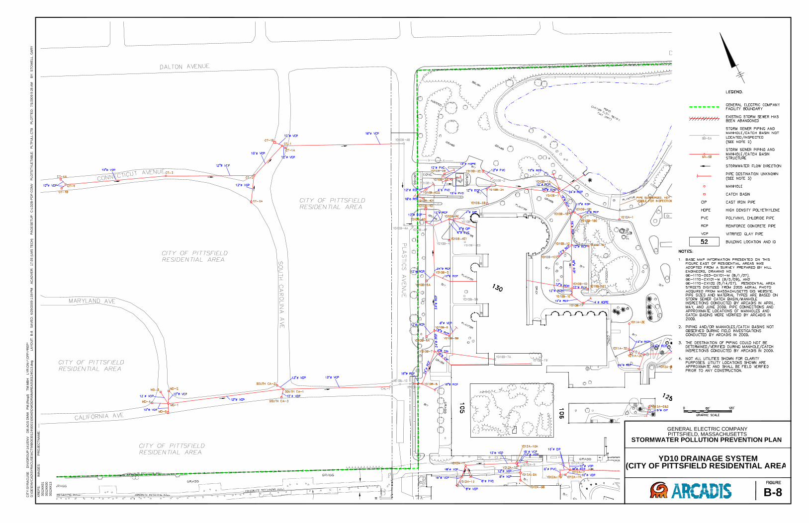
CIT
Y:S
YR
AC
US
ED
IV/G
RO
UP
:14
1/E
NV
DB
:AG
SD
MW
PM
:(R
eqd
)T
M:M
BH
LY
R:O
N=
*;O
FF
=*R
EF
*
G:\G
E\E
NV
CA
D\S
YR
AC
US
E\A
CT
\N\B
00
30
12
4\0
001
\000
40
\DW
G\D
RA
INA
RE
AS
\30124G
13.d
wg
LA
YO
UT
:B
-8S
AV
ED
:6
/29
/20
09
1:0
9P
MA
CA
DV
ER
:1
7.0
S(L
MS
TE
CH
)P
AG
ES
ET
UP
:C
-LD
2B
-PD
F-C
ON
VP
LO
TS
TY
LE
TA
BLE
:P
LT
FU
LL
.CT
BP
LO
TT
ED
:7
/1/2
00
99
:28
AM
BY
:S
TO
WE
LL
,G
AR
Y
YD10 DRAINAGE SYSTEM(CITY OF PITTSFIELD RESIDENTIAL AREA)
GENERAL ELECTRIC COMPANYPITTSFIELD, MASSACHUSETTS
STORMWATER POLLUTION PREVENTION PLAN
B-8
IMA
GE
S:
XR
EF
S:
30124X
01
30124X
00
30124X
13
PR
OJE
CT
NA
ME
:--
--
Appendix C
Employee Training
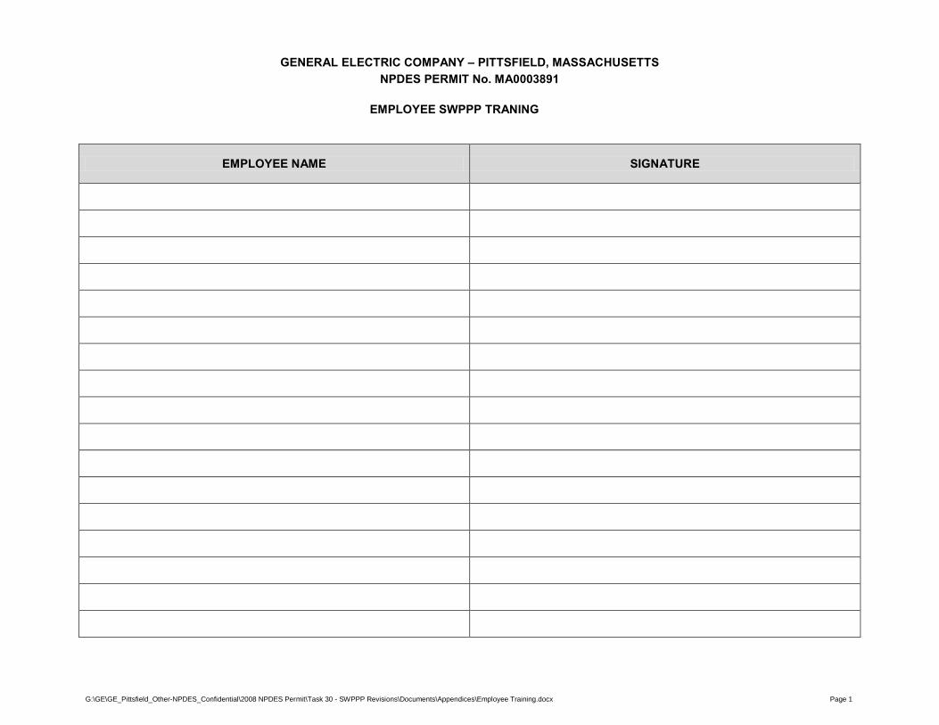
G:\GE\GE_Pittsfield_Other-NPDES_Confidential\2008 NPDES Permit\Task 30 - SWPPP Revisions\Documents\Appendices\Employee Training.docx Page 1
GENERAL ELECTRIC COMPANY – PITTSFIELD, MASSACHUSETTS NPDES PERMIT No. MA0003891
EMPLOYEE SWPPP TRANING
EMPLOYEE NAME SIGNATURE

Appendix D
Inspection Reports and Corrective Actions

TO BE INSERTED FOLLOWING COMPLETION OF INSPECTION ACTIVITIES AND CORRECTIVE ACTIONS (IF NECESSARY)
Appendix E
Description of Reportable Quantity (RQ) Release
DESCRIPTIONS OF REPORTABLE QUANTITIES TO BE INSERTED IF NECESSARY


![Cancer methylomes characterization enabled by Rocker-meth1 day ago · Differentially Methylated Regions (DMRs), are common in cancer tissues with respect to benign cells [19–21]](https://img.pdfslide.us/doc/110x75/603f908c3602f9672a30d788/cancer-methylomes-characterization-enabled-by-rocker-meth-1-day-ago-differentially.jpg)