Embed Size (px)
Citation preview
Village of Wales Comprehensive Development Plan
__________________________________________________________________________________________ Appendix C – Design Guidelines C1
Appendix C
DESIGN GUIDELINES Good general land use planning alone does not ensure a safe and attractive community, since the detailed layout and design of any development is also crucial. To help direct proposed development and redevelopment activities in the Village of Wales and its Historic Village Center, basic design guidelines should be established. The guidelines presented herein are intended to serve as a basis for determining desired physical development layouts and appearances, and not as inflexible, rigid, and narrow rules that may stifle innovative design alternatives. These guidelines should be used by Village officials to provide guidance to applicants and to assist in the evaluation of development proposals including site, landscaping, and building plans. BASIC URBAN AND SITE PLANNING DESIGN GUIDELINES Neighborhoods Neighborhood Units Neighborhoods should be developed in a spatially organized manner around a central feature, or focal point, such as a neighborhood park or elementary school, to promote a sense of physical unity as a planned unit rather than a large, formless, and unidentifiable mass. Neighborhood Identification Delineated neighborhood units, insofar as is practicable, should be bounded by arterial streets; major parks, greenways, or institutional lands; bodies of water or waterways; or other natural or cultural features which serve to clearly define and physically distinguish each unit from the surrounding units. A name should be selected for each neighborhood based on a distinct land feature or land use character, including historic heritage, to provide a sense of identity. Neighborhood Facilities Recreational lands at the neighborhood level should be centrally located to provide a focal point for neighborhood interaction and activities and should be developed, whenever possible, in conjunction with a neighborhood elementary school site. The elementary school and recreational facilities should be provided on a common site available to serve the recreation demands of both the school students and the resident neighborhood population. Individual recreational facility requirements should be based upon the values listed in Table IV-3 of Chapter IV. Neighborhood Access to Facilities Residents of neighborhoods should be provided safe and convenient access to parks, schools, shopping centers, employment areas, and other community facilities. Bicycle and pedestrian ways should be connected to or be a part of a trail system that provides access for both utilitarian and recreational purposes. Neighborhoods should also have ready access to an arterial street system, and, thereby, to urban activities and services, through an internal network of minor and collector streets designed to facilitate vehicular circulation as well as bicycle and pedestrian circulation, while discouraging heavy volumes of arterial traffic through the neighborhood.
Village of Wales Comprehensive Development Plan 7/7/2009
__________________________________________________________________________________________ C2 Appendix C – Design Guidelines
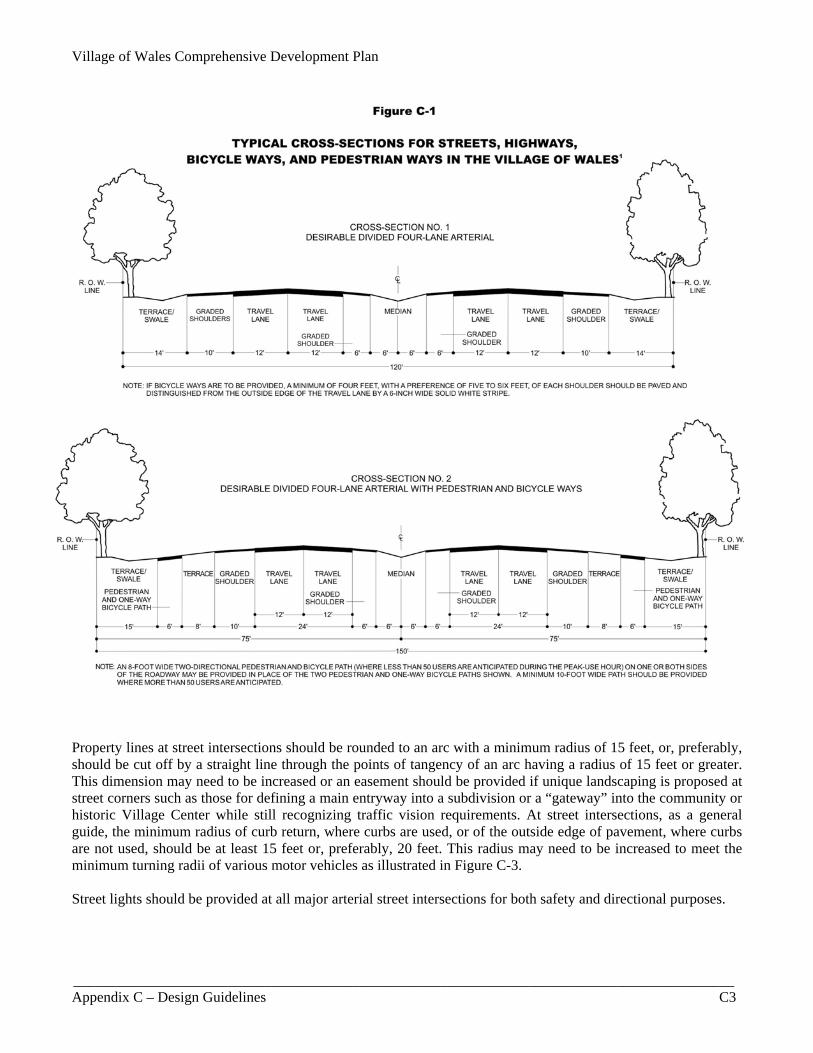
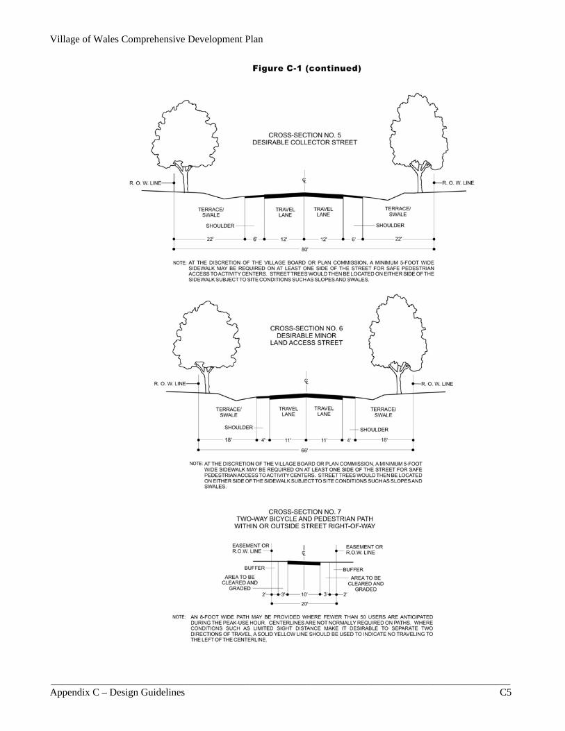
Streets, Bicycle, and Pedestrian Facilities1 Street Cross-Sections The Village’s desired cross-section designs for streets as well as bicycle and pedestrian ways are graphically shown in Figure C-1. Collector and minor land-access streets can generally accommodate bicycle travel without widening the roadway due to the usually low traffic speeds and volumes. Concrete sidewalks or asphalt pedestrian paths should be provided in accordance with a community’s pedestrian and bicycle facilities system plan, since only certain identified street rights-of-way in the plan would be provided with these facilities in order to retain the rural, country character and yet make some provision for safe access to trails, parks, schools, shopping areas, and other points of interest. Roadside Swales and Curbing Most streets within the Village use roadside swales without curbing for stormwater drainage, which conveys a more rural appearance. Side slopes of roadside swales should preferably not exceed one foot vertically to every four feet horizontally, but no steeper than one to three. Side slopes steeper than one to four are not only more difficult to mow, but do not blend well with natural land forms. Curbing should be provided at street intersections and in certain other areas, where necessary, for proper stormwater management. Such curbing should preferably be mountable curbs, also referred to as roll-face curbs as shown in Figure C-2, which projects a less rigid, harsh edge than vertical-faced curbs, which have a more urban appearance. Street Grades Unless necessitated by exceptional topography, the maximum grade of any street should not exceed 6 percent for arterial and collector streets, and 10 percent for minor land-access streets, alleys, and frontage streets. The grade of any street should in no case exceed 10 percent. The minimum grade of any street should preferably be 0.75 percent, and in no case be less than 0.50 percent, except those with curb and gutter may contain a minimum grade of 0.30 percent where the surrounding terrain dictates. The grade of road crowns should be no less than 1.5 percent with a desirable grade of 2 percent and a maximum grade of 3 percent. The change in grade across a street intersection within 100 feet of the centerline should desirably not exceed 3 percent where practical. All street grades should be established so as to avoid excessive grading, the promiscuous removal of ground cover and trees, and indiscriminate leveling of the terrain. Street Intersections Streets should intersect each other as nearly right angles as topography and other limiting factors of good design permit. Angles above approximately 60 degrees usually produce only a small reduction in visibility, which often does not warrant realignment closer to 90 degrees. In addition, the number of streets converging at one intersection should be held to a minimum, preferably to not more than two streets at one intersection; the location of street intersections immediately below the crest of hills should be avoided; the number of intersections along arterial streets and highways should be held to a minimum; and the distance between such intersections should generally not be less than 1,200 feet measured from the centerline of each street. Minor land-access street openings onto arterial streets should be minimized to improve traffic flow and reduce traffic hazards.
–––––––––––– 1The design guidelines set forth in this section are not intended to serve as a comprehensive guide to the design of streets and highways, including those accommodating bicycle and pedestrian facilities, but are intended to suggest the general type of design treatments that may be appropriate in certain situations. Precise design specification should be determined during engineering studies for specific street, highway, and bicycle-way projects, and should be based, in part, on the recommendations contained in the most recent edition of A Policy on Geometric Design of Highways and Streets and the Guide for the Development of Bicycle Facilities, both published by the American Association of State Highway and Transportation Officials, and the Manual on Uniform Traffic Control Devices, published by the U.S. Department of Transportation, Federal Highway Administration.
Village of Wales Comprehensive Development Plan
__________________________________________________________________________________________ Appendix C – Design Guidelines C3
Property lines at street intersections should be rounded to an arc with a minimum radius of 15 feet, or, preferably, should be cut off by a straight line through the points of tangency of an arc having a radius of 15 feet or greater. This dimension may need to be increased or an easement should be provided if unique landscaping is proposed at street corners such as those for defining a main entryway into a subdivision or a “gateway” into the community or historic Village Center while still recognizing traffic vision requirements. At street intersections, as a general guide, the minimum radius of curb return, where curbs are used, or of the outside edge of pavement, where curbs are not used, should be at least 15 feet or, preferably, 20 feet. This radius may need to be increased to meet the minimum turning radii of various motor vehicles as illustrated in Figure C-3. Street lights should be provided at all major arterial street intersections for both safety and directional purposes.

Village of Wales Comprehensive Development Plan 7/7/2009
__________________________________________________________________________________________ C4 Appendix C – Design Guidelines
Figure C-1 (continued)
Street Jogs Street jogs with centerline offsets of less than 250 feet along arterial streets or less than 125 feet along nonarterial streets should be avoided. Minor and collector streets need not necessarily continue across arterial streets. Street Curvatures When a continuous street centerline deflects at any point by more than seven degrees, a circular curve should be introduced with a radius of curvature on the centerline of not less than the following: arterial streets, 500 feet; collector streets, 300 feet; and minor streets, 100 feet. A tangent at least 100 feet in length should be provided between reverse curves on arterial and collector streets. All changes in street grades that exceed one percent should be connected by vertical curves that meet the standards for stopping sight distance established in the American Association of State Highway and Transportation Officials, A Policy on Geometric Design of Highways and Streets. Minimum curve radii should be further based on the function of traffic speed, sight distances, and other factors.
Village of Wales Comprehensive Development Plan
__________________________________________________________________________________________ Appendix C – Design Guidelines C5
Village of Wales Comprehensive Development Plan 7/7/2009
__________________________________________________________________________________________ C6 Appendix C – Design Guidelines
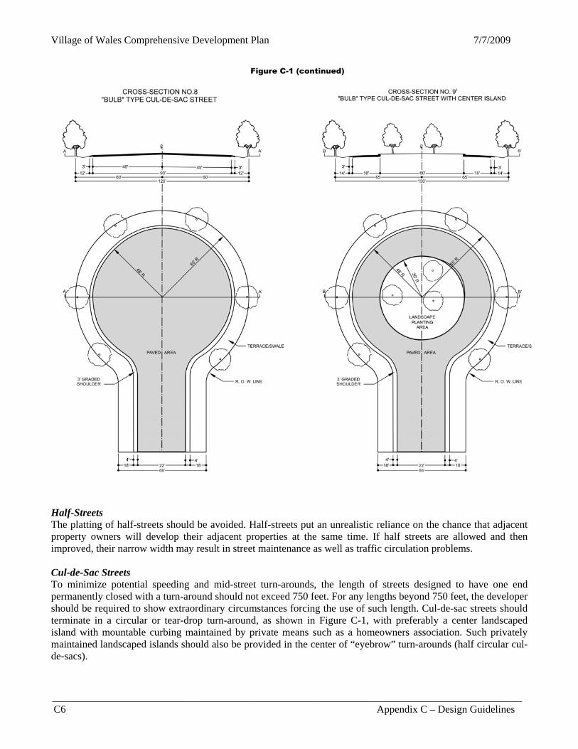
Figure C-1 (continued)
Half-Streets The platting of half-streets should be avoided. Half-streets put an unrealistic reliance on the chance that adjacent property owners will develop their adjacent properties at the same time. If half streets are allowed and then improved, their narrow width may result in street maintenance as well as traffic circulation problems. Cul-de-Sac Streets To minimize potential speeding and mid-street turn-arounds, the length of streets designed to have one end permanently closed with a turn-around should not exceed 750 feet. For any lengths beyond 750 feet, the developer should be required to show extraordinary circumstances forcing the use of such length. Cul-de-sac streets should terminate in a circular or tear-drop turn-around, as shown in Figure C-1, with preferably a center landscaped island with mountable curbing maintained by private means such as a homeowners association. Such privately maintained landscaped islands should also be provided in the center of “eyebrow” turn-arounds (half circular cul-de-sacs).
Village of Wales Comprehensive Development Plan
__________________________________________________________________________________________ Appendix C – Design Guidelines C7
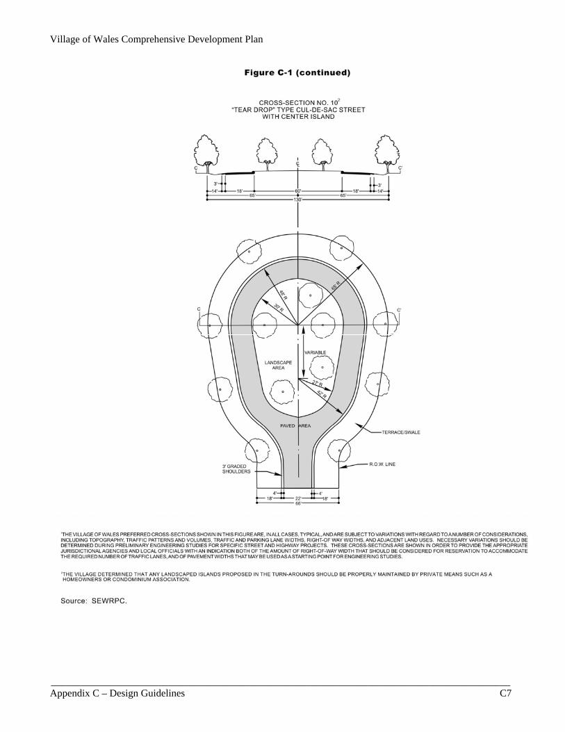
Figure C-1 (continued)

Village of Wales Comprehensive Development Plan 7/7/2009
__________________________________________________________________________________________ C8 Appendix C – Design Guidelines
Figure C-2
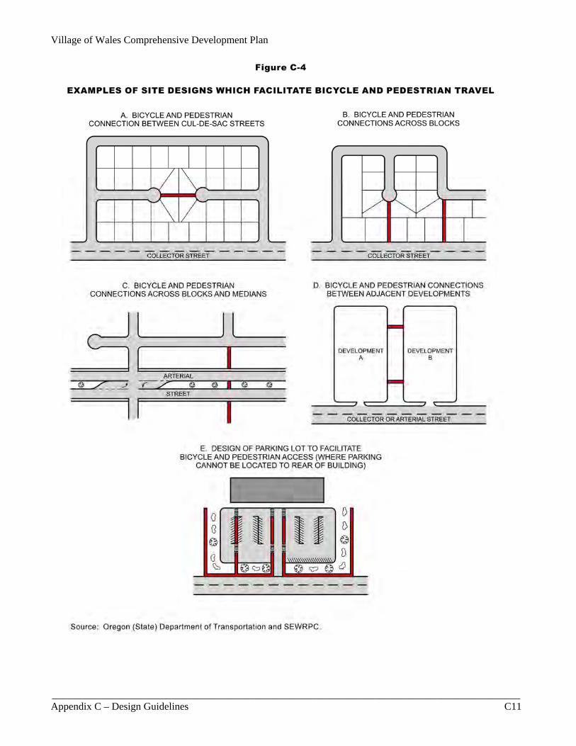
TYPICAL MOUNTABLE CURB CROSS-SECTION Curb Ramps Curb ramps should be provided in accordance with the Americans with Disabilities Act and with Section 66.0909 of the Wisconsin Statutes. Bicycle and Pedestrian Facilities Bikeways2 and pedestrian facilities should be afforded safe and convenient access to activity centers and places of employment. The provision of such facilities should be based, in part, on Figure C-1 and the planning and design standards established in SEWRPC Planning Report No. 43, A Regional Bicycle and Pedestrian Facilities System Plan for Southeastern Wisconsin: 2010, which includes specific design guidelines such as desirable grades, sight distances, pavement widths, crosswalks, and other standards. Off-street bike and pedestrian ways should be provided to connect cul-de-sac streets and adjacent streets across blocks of 900 feet or longer, and should be provided to connect adjacent subdivisions, subdivisions and activity centers, and activity centers and employment centers where alternative on-street routes are unduly circuitous. Examples of site designs that facilitate bicycle and pedestrian travel are illustrated in Figure C-4.
–––––––––––– 2A “bikeway” is a general term that includes any road, path, or way that may legally be used for bicycle travel. Types of bikeways include “bike paths,” which are physically separated from motorized vehicles; “bike lanes,” which are portions of roadways that are designated by striping, signing, and pavement markings for the exclusive or preferential use by bicycles; and “shared roadways,” which are roadways that do not have a designated bike lane, but may be legally used for bicycle travel. A “bike route” is a bikeway designated with directional and information markers, and may consist of a combination of bike paths, bike lanes, and shared roadways.

Village of Wales Comprehensive Development Plan
__________________________________________________________________________________________ Appendix C – Design Guidelines C9
Village of Wales Comprehensive Development Plan 7/7/2009
__________________________________________________________________________________________ C10 Appendix C – Design Guidelines
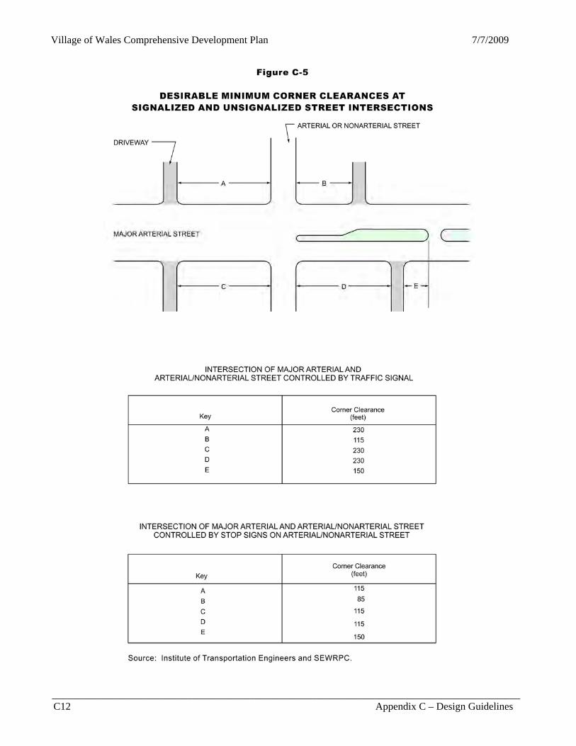
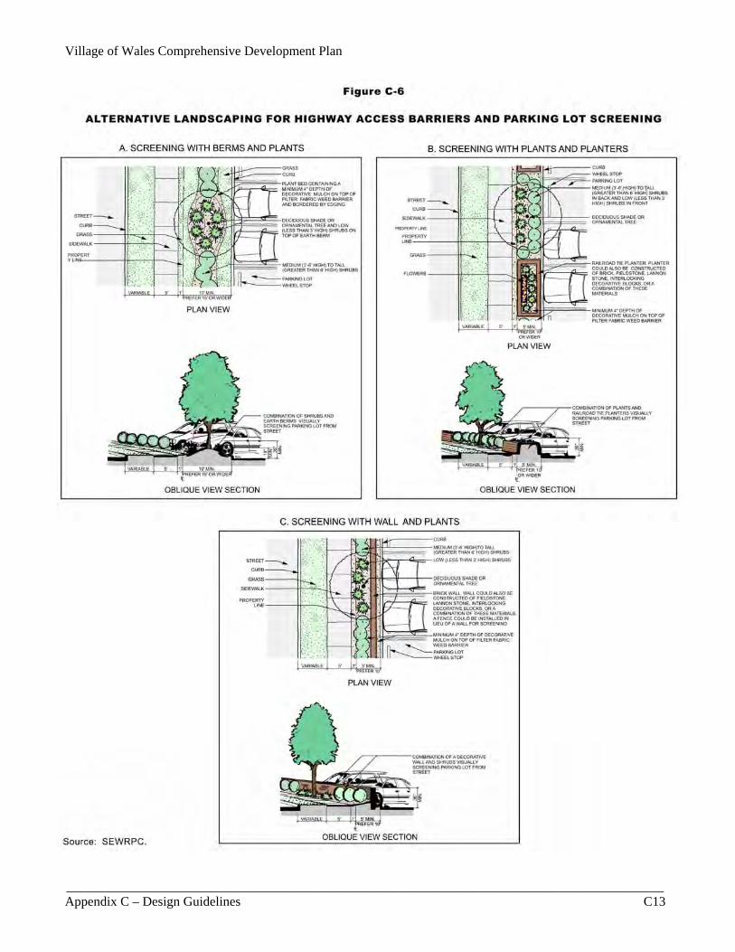
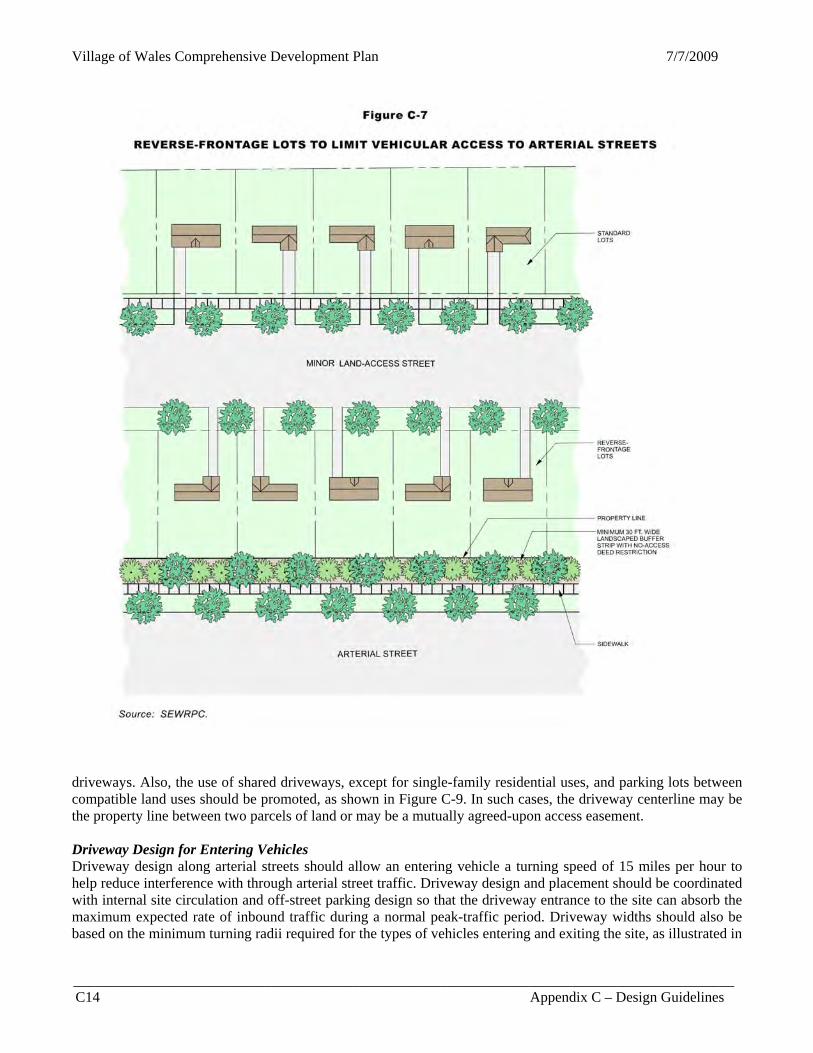
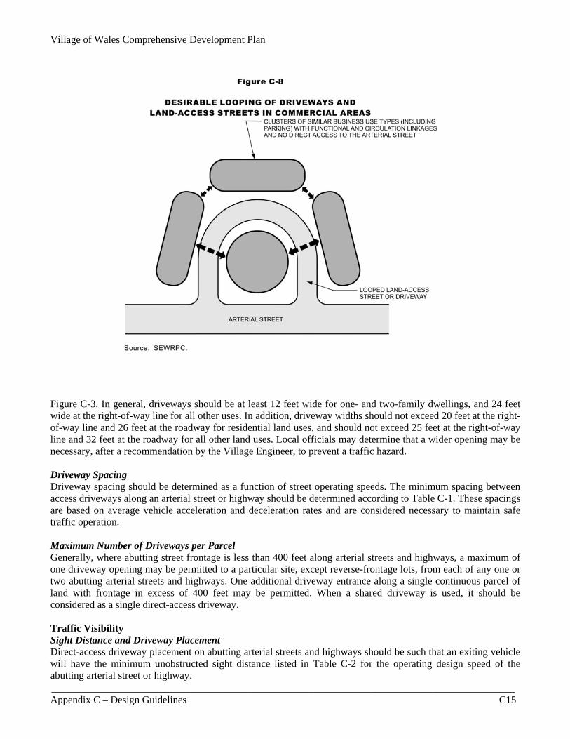
Whenever a street or highway that is designated as a bikeway on an adopted bicycle-way facility system plan is going to being constructed, reconstructed, or resurfaced, such streets should accommodate bicyclists in accordance with Figure C-1. On limited street rights-of-way with roadside swales and low traffic speed and volumes, a paved shoulder with a width of at least four feet, and preferably five or six feet, should be provided to accommodate bicyclists if a separate path is impractical. Vehicular Access Access and Street Intersections Driveways on corner lots should be set back sufficiently from intersecting streets so that they do not interfere with traffic movement. The corner clearance between new direct public or private access and an arterial street intersection should be a minimum of 115 to 230 feet or, preferably, 250 feet where land parcel size permits, as illustrated in Figure C-5. The clearance distance is defined as the distance between the nearest face of curb or edge of pavement of the intersecting street and the nearest face of curb or edge of pavement of the nearest access point upstream or downstream of the intersection. Arterial Highway Access Barriers No-access easements for motorized vehicles and physical barriers, such as ditching, curbing, fencing, plantings, berms, or other landscape barriers, should be provided to prevent undesirable vehicular access to arterial streets or highways and to properly and safely channelize traffic movements. When plantings are used as an access barrier, the width of the landscaped area should be at least 10 feet. If berms are used as barriers, the width of the landscaped area should be able to accommodate the size of the berms, based on their slope, crown, height, and form. When structural barriers are used, the minimum width could be five feet, preferably wider, with landscaping such as trees and shrubs provided between the structure and adjacent right-of-way. Where applicable, openings should be provided in the barriers for convenient bicycle and pedestrian access to adjacent streets. The vision clearance triangle standards discussed herein should also be observed. Figure C-6 illustrates alternative landscaping methods for barriers with parking lot screening. Reverse-Frontage Lots to Limit Arterial Highway Access Reverse-frontage lots should be located adjacent to arterial streets or highways to limit vehicular access from abutting land uses. A landscaped buffer strip at least 30 feet wide, or preferably wider, should be provided with a nonaccess reservation along the rear property lines of residential reverse-frontage lots, as shown in Figure C-7. The landscaped buffer strip should be completed as part of a development to ensure proper installation and design continuity. Normal lot depths should be increased by the width of the buffer strip. Looped Land-Access Streets and Shared Driveways/Traffic Aisles Looped land-access streets and shared drives should be used, when feasible, to help reduce the potential number of driveway intersections along an arterial for commercial areas, as illustrated in Figure C-8. In cases where parking lots are located in the front yard, shared traffic aisles should be used between adjoining compatible uses, such as abutting commercial uses, that are aligned parallel with arterial streets to help reduce the number of access points and vehicles entering onto and exiting off the arterials. Alignments and Shared-Use of Driveways Driveways should intersect each other and streets at as nearly right angles as topography and other limiting factors of good design permit. Driveway entrances along both sides of an arterial should be aligned as illustrated in Figure C-9 to help reduce the number of driveways needed and limit some of the confusion caused by unaligned
Village of Wales Comprehensive Development Plan
__________________________________________________________________________________________ Appendix C – Design Guidelines C11
Figure C-4
EXAMPLES OF SITE DESIGNS WHICH FACILITATE BICYCLE AND PEDESTRIAN TRAVEL
Source: Oregon (State) Department of Transportation and SEWRPC.
Village of Wales Comprehensive Development Plan 7/7/2009
__________________________________________________________________________________________ C12 Appendix C – Design Guidelines
Figure C-5
DESIRABLE MINIMUM CORNER CLEARANCES AT SIGNALIZED AND UNSIGNALIZED STREET INTERSECTIONS
Source: Institute of Transportation Engineers and SEWRPC.
Village of Wales Comprehensive Development Plan
__________________________________________________________________________________________ Appendix C – Design Guidelines C13
Figure C-6
ALTERNATIVE LANDSCAPING FOR HIGHWAY ACCESS BARRIERS AND PARKING LOT SCREENING
Village of Wales Comprehensive Development Plan 7/7/2009
__________________________________________________________________________________________ C14 Appendix C – Design Guidelines
Figure C-7
REVERSE-FRONTAGE LOTS TO LIMIT VEHICULAR ACCESS TO ARTERIAL STREETS driveways. Also, the use of shared driveways, except for single-family residential uses, and parking lots between compatible land uses should be promoted, as shown in Figure C-9. In such cases, the driveway centerline may be the property line between two parcels of land or may be a mutually agreed-upon access easement. Driveway Design for Entering Vehicles Driveway design along arterial streets should allow an entering vehicle a turning speed of 15 miles per hour to help reduce interference with through arterial street traffic. Driveway design and placement should be coordinated with internal site circulation and off-street parking design so that the driveway entrance to the site can absorb the maximum expected rate of inbound traffic during a normal peak-traffic period. Driveway widths should also be based on the minimum turning radii required for the types of vehicles entering and exiting the site, as illustrated in
Village of Wales Comprehensive Development Plan
__________________________________________________________________________________________ Appendix C – Design Guidelines C15
Figure C-8
DESIRABLE LOOPING OF DRIVEWAYS AND LAND-ACCESS STREETS IN COMMERCIAL AREAS
Figure C-3. In general, driveways should be at least 12 feet wide for one- and two-family dwellings, and 24 feet wide at the right-of-way line for all other uses. In addition, driveway widths should not exceed 20 feet at the right-of-way line and 26 feet at the roadway for residential land uses, and should not exceed 25 feet at the right-of-way line and 32 feet at the roadway for all other land uses. Local officials may determine that a wider opening may be necessary, after a recommendation by the Village Engineer, to prevent a traffic hazard. Driveway Spacing Driveway spacing should be determined as a function of street operating speeds. The minimum spacing between access driveways along an arterial street or highway should be determined according to Table C-1. These spacings are based on average vehicle acceleration and deceleration rates and are considered necessary to maintain safe traffic operation. Maximum Number of Driveways per Parcel Generally, where abutting street frontage is less than 400 feet along arterial streets and highways, a maximum of one driveway opening may be permitted to a particular site, except reverse-frontage lots, from each of any one or two abutting arterial streets and highways. One additional driveway entrance along a single continuous parcel of land with frontage in excess of 400 feet may be permitted. When a shared driveway is used, it should be considered as a single direct-access driveway. Traffic Visibility Sight Distance and Driveway Placement Direct-access driveway placement on abutting arterial streets and highways should be such that an exiting vehicle will have the minimum unobstructed sight distance listed in Table C-2 for the operating design speed of the abutting arterial street or highway.

Village of Wales Comprehensive Development Plan 7/7/2009
__________________________________________________________________________________________ C16 Appendix C – Design Guidelines
Figure C-9
DESIRABLE ALIGNMENT AND SHARED USE OF DRIVEWAYS AND PARKING LOTS IN COMMERCIAL AREAS
Source: SEWRPC.
Table C-1
HIGHWAY OPERATING SPEED AND MINIMUM SPACING BETWEEN
DIRECT-ACCESS DRIVEWAYS
Highway Speed Limit (mph)
Minimum Spacing (feet)
25 105
30 125
35 150
40 185
45 230
50 275 Source: American Planning Association and the Wisconsin Department of Transportation.
Table C-2
HIGHWAY DESIGN SPEED AND MINIMUM REQUIRED SIGHT DISTANCE
FOR DIRECT-ACCESS DRIVEWAY PLACEMENT
Highway Design Speed Limit (mph)
Minimum Sight Distance (feet)
Desirable Sight Distance
(feet)
30 200 200
35 225 250
40 275 325
45 325 400
50 400 475 Source: American Association of State Highway and Transportation Officials and
the Wisconsin Department of Transportation.
Village of Wales Comprehensive Development Plan
__________________________________________________________________________________________ Appendix C – Design Guidelines C17
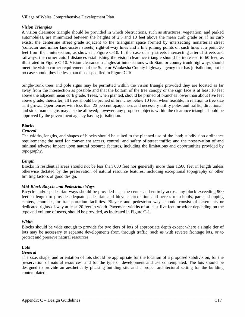
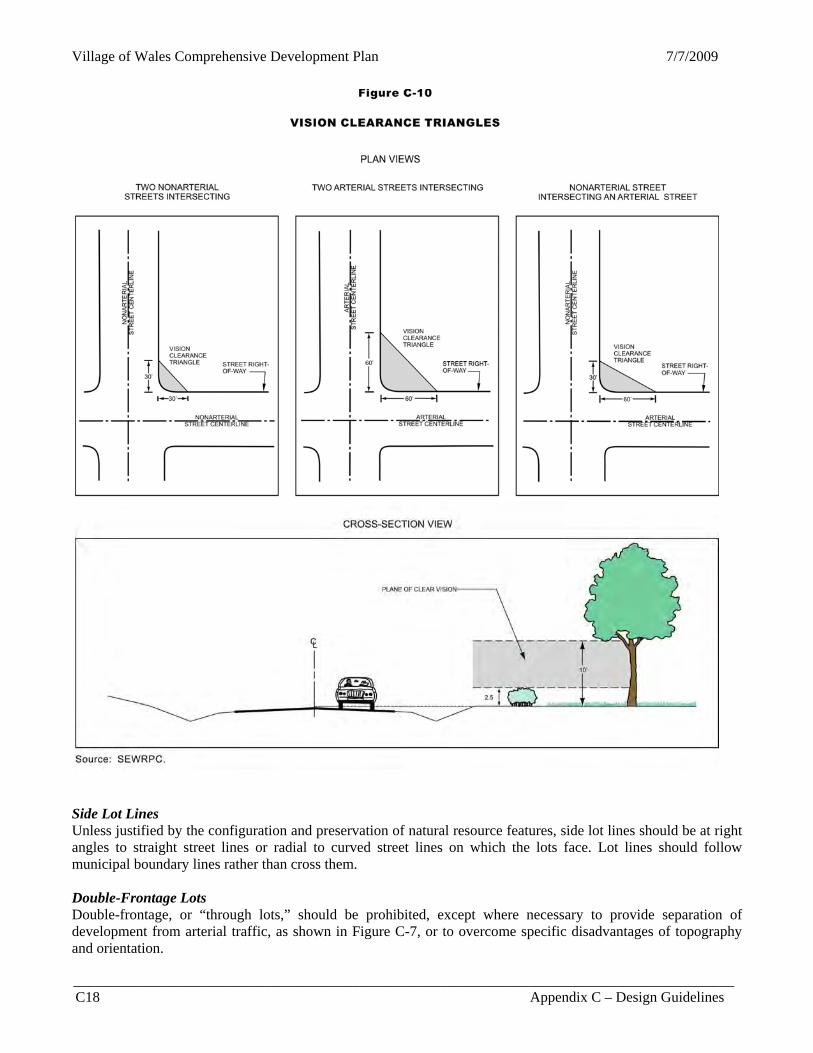
Vision Triangles A vision clearance triangle should be provided in which obstructions, such as structures, vegetation, and parked automobiles, are minimized between the heights of 2.5 and 10 feet above the mean curb grade or, if no curb exists, the centerline street grade adjacent to the triangular space formed by intersecting nonarterial street (collector and minor land-access streets) right-of-way lines and a line joining points on such lines at a point 30 feet from their intersection, as shown in Figure C-10. In the case of any streets intersecting arterial streets and railways, the corner cutoff distances establishing the vision clearance triangle should be increased to 60 feet, as illustrated in Figure C-10. Vision clearance triangles at intersections with State or county trunk highways should meet the vision corner requirements of the State or Waukesha County highway agency that has jurisdiction, but in no case should they be less than those specified in Figure C-10.
Single-trunk trees and pole signs may be permitted within the vision triangle provided they are located as far away from the intersection as possible and that the bottom of the tree canopy or the sign face is at least 10 feet above the adjacent mean curb grade. Trees, when planted, should be pruned of branches lower than about five feet above grade; thereafter, all trees should be pruned of branches below 10 feet, when feasible, in relation to tree size as it grows. Open fences with less than 25 percent opaqueness and necessary utility poles and traffic, directional, and street name signs may also be allowed; however, any proposed objects within the clearance triangle should be approved by the government agency having jurisdiction. Blocks General The widths, lengths, and shapes of blocks should be suited to the planned use of the land; subdivision ordinance requirements; the need for convenient access, control, and safety of street traffic; and the preservation of and minimal adverse impact upon natural resource features, including the limitations and opportunities provided by topography. Length Blocks in residential areas should not be less than 600 feet nor generally more than 1,500 feet in length unless otherwise dictated by the preservation of natural resource features, including exceptional topography or other limiting factors of good design. Mid-Block Bicycle and Pedestrian Ways Bicycle and/or pedestrian ways should be provided near the center and entirely across any block exceeding 900 feet in length to provide adequate pedestrian and bicycle circulation and access to schools, parks, shopping centers, churches, or transportation facilities. Bicycle and pedestrian ways should consist of easements or dedicated rights-of-way at least 20 feet in width. Pavement widths of at least five feet, or wider depending on the type and volume of users, should be provided, as indicated in Figure C-1. Width Blocks should be wide enough to provide for two tiers of lots of appropriate depth except where a single tier of lots may be necessary to separate developments from through traffic, such as with reverse frontage lots, or to protect and preserve natural resources. Lots General The size, shape, and orientation of lots should be appropriate for the location of a proposed subdivision, for the preservation of natural resources, and for the type of development and use contemplated. The lots should be designed to provide an aesthetically pleasing building site and a proper architectural setting for the building contemplated.
Village of Wales Comprehensive Development Plan 7/7/2009
__________________________________________________________________________________________ C18 Appendix C – Design Guidelines
Figure C-10
VISION CLEARANCE TRIANGLES Side Lot Lines Unless justified by the configuration and preservation of natural resource features, side lot lines should be at right angles to straight street lines or radial to curved street lines on which the lots face. Lot lines should follow municipal boundary lines rather than cross them. Double-Frontage Lots Double-frontage, or “through lots,” should be prohibited, except where necessary to provide separation of development from arterial traffic, as shown in Figure C-7, or to overcome specific disadvantages of topography and orientation.
Village of Wales Comprehensive Development Plan
__________________________________________________________________________________________ Appendix C – Design Guidelines C19
Access In general, every lot should front or abut a public street. Lot Size Lot sizes should contain sufficient area to adequately accommodate buildings, parking, landscaping, screening, and all required yards. Area and dimensions of all lots should conform to the requirements of the Village zoning ordinance. Lot Depth and Proportion It is recommended that the depth of new lots generally should not be less than 125 feet. Normal lot depths should be increased relative to the width of any buffer strips provided along abutting arterial streets, highways, and railways. In certain cases, the depth should be increased to accommodate shared land-access roads or traffic aisles between adjoining compatible uses and aligned parallel with arterial streets to help reduce the number of access points along arterials. Excessive depth of lots in relation to width should be avoided whenever possible unless justified for the preservation of natural resources; a proportion of two-and-one-half to one (2.5:1) is suggested as a maximum depth-to-width ratio. Flag lots should be avoided whenever possible, except where necessary to preserve natural resources or overcome specific disadvantages of topography and/or orientation. Lot Width Lots within the interior of a block should have a width at the building setback line that conforms to the Village zoning ordinance. In general, required minimum lot widths should be increased if a utility easement, bicycle way, pedestrian way, or a landscaped buffer strip is provided. Corner Lots Corner lots should have an additional width of at least 20 feet to permit adequate building setbacks from side streets. Commercial Spatial Considerations Commercial Business Clustering Businesses with similar characteristics should form commercial clusters versus strips within proximity of one another in order to better define identifiable commercial areas for the user, provide functional linkages of similar business types, and provide circulation linkages for vehicular, bicycle, and pedestrian traffic. Businesses may be located so as to form the following three general types of clusters:
1. Shopping center retail sales and services characterized by onsite parking for customer automobiles and a pedestrian-oriented shopping environment. Uses in this category would include general merchandise stores, food stores, apparel and accessory stores, drug stores, department stores, gift shops, cleaners, barbers and hairdressers, banks and savings and loan institutions, and restaurants (other than drive-in or drive-through).
2. Automobile-oriented retail sales and services characterized by sales and services to commercial
customers in the automobile. These types of commercial uses are not pedestrian oriented. Uses in this category include gasoline stations, automobile sales and service, car washes, drive-in banking, drive-in/drive-through restaurants, hotels, motels, and “big-box” retail stores.
3. Offices, including professional offices, medical offices, dental offices, clinics, and printing and photo
reproduction services.
Village of Wales Comprehensive Development Plan 7/7/2009
__________________________________________________________________________________________ C20 Appendix C – Design Guidelines
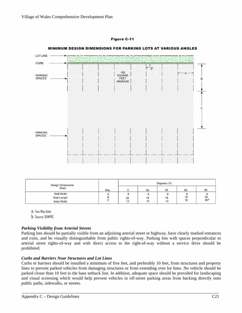
Traffic Circulation between Adjacent Properties Provision for traffic circulation between adjacent commercial uses should be provided through coordinated access drives, shared parking lots, and interconnecting bicycle and pedestrian ways as shown in Figures C-4, C-8, and C-9. Onsite Vehicular Circulation The vehicular circulation system within and around individual commercial parcels should be developed so as to provide easy access to parking facilities from the larger community without lessening the safety or capacity of arterials. Conflicts between vehicles and pedestrians should be avoided where possible and, where conflicts cannot be totally avoided, conflicts should be minimized. Also, delivery and service circulation patterns on the site should not conflict with customer circulation. Onsite Queued Vehicle Storage Sufficient onsite space should be provided to accommodate at least three queued vehicles waiting to park or exit the parking lot without utilizing any portion of the arterial street right-of-way or interfering with arterial street traffic and safety. For drive-through services, queuing area to accommodate at least seven vehicles should be provided onsite. Onsite Service and Loading Areas Service and loading areas should be located for convenient service vehicle access. Service and loading areas should not conflict with pedestrian or general vehicular traffic in the area. Also, service and loading areas should be screened or located in the rear of buildings to shield them from view by the public and customers. Parking Lots Number of Parking Spaces Parking spaces should be provided in sufficient number to meet the applicable zoning requirements. Reserved parking stalls should be provided for the physically disabled pursuant to the Americans with Disabilities Act and Section 346.503 of the Wisconsin Statutes. When warranted, modification to the minimum number of parking spaces required should be allowed to avoid constructing unneeded and excessive impervious surfaces in areas that could otherwise be preserved or converted to landscaped open space. Parking Lot Location Parking lots should be so sited as to minimize walking distances to the facility the parking lot is serving. Parking spaces for the disabled should be located as close as possible to a building entrance which allows such persons to enter and leave the parking area without assistance and, if possible, without crossing traffic lanes or passing behind other parked vehicles. Parking Lot Dimensions Minimum design dimensions for parking lots are shown in Figure C-11. Dimensions for handicapped parking spaces should comply with those established in the Americans with Disabilities Act. Parking Lot Drive Width Parking lot drives should have a minimum width as specified in Figure C-11 based on the parking space angle and whether the drive or traffic aisle will accommodate one- or two-way traffic. Surfacing All traffic aisles and off-street parking areas should be graded and hard-surfaced with concrete or asphalt so as to be dust-free and properly drained. Parking areas for five or more vehicles should have the aisles and parking spaces clearly marked in order to distinguish between parking stalls and vehicular circulation areas.
Village of Wales Comprehensive Development Plan
__________________________________________________________________________________________ Appendix C – Design Guidelines C21
Parking Visibility from Arterial Streets Parking lots should be partially visible from an adjoining arterial street or highway, have clearly marked entrances and exits, and be visually distinguishable from public rights-of-way. Parking lots with spaces perpendicular to arterial street rights-of-way and with direct access to the right-of-way without a service drive should be prohibited. Curbs and Barriers Near Structures and Lot Lines Curbs or barriers should be installed a minimum of five feet, and preferably 10 feet, from structures and property lines to prevent parked vehicles from damaging structures or from extending over lot lines. No vehicle should be parked closer than 10 feet to the base setback line. In addition, adequate space should be provided for landscaping and visual screening which would help prevent vehicles in off-street parking areas from backing directly onto public paths, sidewalks, or streets.
a. Two-Way Aisle
b. Source: SEWPRC
Village of Wales Comprehensive Development Plan 7/7/2009
__________________________________________________________________________________________ C22 Appendix C – Design Guidelines
Parking Lot Lighting Parking lot lighting should serve four purposes. First, the lighting should provide for the safe movement of pedestrian and vehicular traffic. Second, it should aid in the provision of an environment which promotes security and crime prevention. Third, the lighting should aid in creating an aesthetically pleasing environment at nighttime, as well as during the daylight hours. Fourth, the lighting for commercial parking lots should assist in promoting the use of commercial facilities both day and night. Parking lots should be lit to meet current standards issued by the Illuminating Engineering Society of North America (IESNA),3 which ranges from 0.2 to 2.0 footcandles based on the type of use the parking lot is serving as well as the extent of desired security. All outside lighting should be arranged and shielded to prevent glare, reflection, nuisance, inconvenience, or hazardous interference of any kind on, to, or with adjoining streets or residential properties. The intensity of illumination should not exceed 0.5 footcandles at property lines. In general, the height of the light fixture lens from the ground level should not exceed 20 feet, and the pole should be placed at least four feet from tire-stops or paved areas, or protected by other approved means. All wiring should be placed underground. Landscaping General A landscape design for a site should be integrated with the overall site plan and consistent with the desired community character, and not be considered merely as an afterthought. Landscaping enhances the overall attractiveness of a community and contributes to the general welfare of the public by providing shade, shelter, and screening. Plants selected for use in the urban environment, such as in parking lots and along streets, should be salt-tolerant. Decorative mulch, such as stone or shredded hardwood bark, with underlying filter fabric weed barrier should be used in lieu of turf grass where heavy pedestrian and vehicular traffic is present or where the availability of water is limited. If such grass is proposed in landscaped areas, it should be properly maintained and protected from pedestrian and vehicular traffic, otherwise an “all-weather” surface material should be used, such as decorative pavement surface or stone mulch with underlying weed barrier. Excessive pavement of open space areas with hard-surface materials such as asphalt or concrete should be discouraged. Flower beds should only be provided if provisions are made for proper maintenance. Berms are beneficial for plants, especially if more suitable planting soil is placed above areas containing poor soil and drainage. Invasive plants identified in Appendix D should not be used in landscaping. The finished side of fences should face the street or neighboring property with the supporting structural components of the fence facing away from adjacent streets or properties. In addition, any proposed landscaping should recognize traffic safety requirements including those for sight distances, vision triangles, and vehicular recovery areas. Natural native plants, including prairie grass and wildflowers, should be used in areas of steep topography, along rural roadways, and in designated “natural” areas of parks and greenways to preserve or achieve a natural appearance while reducing maintenance cost. To preserve water supply, natural landscaping and xericscaping—a landscape arrangement with plants that require minimal water—should be encouraged. Existing Vegetation Every effort should be made to protect and retain existing native trees, shrubbery, vines, and grasses not actually lying in public streets, drainageways, paths, and trails. Removal of existing vegetation should be minimized and, when permitted, cutting and clearing should be conducted so as to prevent erosion and sedimentation and to preserve and improve scenic qualities. Existing invasive plants identified in Appendix D, however, should be –––––––––––– 3Lighting standards should be based on the most recent edition of IESNA Document RP-20, Lighting for Parking Facilities. The recommended illumination values provided are meaningful only when used in conjunction with other elements. The most critical elements are luminaire mounting height, spacing, transverse location of luminaries, luminaire selection, traffic conflict areas, border areas, transition lighting, alleys, and roadway lighting layouts.
Village of Wales Comprehensive Development Plan
__________________________________________________________________________________________ Appendix C – Design Guidelines C23
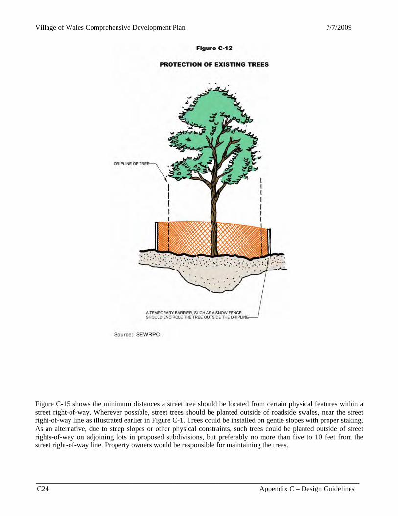
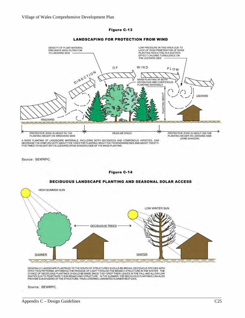
properly removed. Trails constructed in environmentally sensitive areas should be designed so as to result in the least removal and disruption of vegetation with minimal impairment to the natural beauty of the area. Trees should be protected and preserved during construction as illustrated in Figure C-12 and in accordance with sound tree conservation practices, including the use of wells, islands, or retaining walls whenever abutting grades are altered. Special consideration should be given to preventing soil compaction and stockpiling of soil or construction materials in existing tree root zones, even if such placement is temporary. Wind and Landscape Planting Landscaping should be provided to minimize winter wind and to promote summer wind effects on structures. Winter wind protection is afforded by providing landscaping of an adequate height on the west side of buildings. An optimum distance between a windbreak and a building is approximately twice the height of the windbreak. A wind-break consisting of two rows of coniferous trees is nearly optimal for efficiency, and additional rows would not significantly increase its effectiveness as a windbreak. Figure C-13 illustrates the concept. Noise and Landscaping Groups of trees, shrubs, and other landscape masses, such as earth berms or ornate solid fences and walls, can serve as noise barriers and should be utilized where noise could create problems for neighboring land uses. Such landscaped noise barriers are most effective when the barrier is near the noise source or receiver. Solar Access and Landscape Planting With respect to solar access, plants installed to the south of structures should be deciduous species with a broad branching habit and open twig patterns that would provide shading in the summer and permit sunlight through the branches in the winter. Figure C-14 illustrates these concepts. Selection of Landscape Plants Trees and shrubs, meeting the most recent edition of the American Association of Nurseryman’s Standards for nursery stock, should be planted at appropriate intervals along public rights-of-way, adjacent to buildings, and in other designated onsite planting areas. The type of planting should be determined by the topographic features and microclimate of the site. The spacing of plants should be determined by soil conditions, land use, terrace width, utility locations, and design theme. Appendix E sets forth the species characteristics of various trees, shrubs, ornamental grasses, groundcovers, and vines to aid in the selection of landscape plantings based, in part, upon species hardiness to environmental conditions. For regulatory purposes, Appendix E also recommends desirable sizes and spacing of certain plant species to be used for buffering or screening. The installation of flowers should only be encouraged if properly maintained; otherwise, groundcover or ornamental grasses could be used, which require little maintenance. Street Trees Street trees should be provided along public rights-of-way to reduce air temperature by providing shade, and reduce air pollutants by converting carbon monoxide to carbon dioxide. Appendix F provides a list of trees that may be used as street trees. A minimum of one deciduous shade tree of at least two inches in diameter measured 4.5 feet—about chest height—above ground level and meeting the American Association of Nurserymen’s Standards for nursery stock should be planted for each 50 feet of street frontage. In certain areas, trees could have some randomness or informality, such as staggering, in their arrangement to avoid the urban appearance that regular spacing may evoke, and could be planted closer together than suggested in Appendix F depending on the type of tree selected, the desired design effect to be achieved, and the amount and quality of growing space provided for the root system. Existing healthy trees that are noninvasive and properly protected should be allowed to count towards a community’s street tree requirement.
Village of Wales Comprehensive Development Plan 7/7/2009
__________________________________________________________________________________________ C24 Appendix C – Design Guidelines
Figure C-12
PROTECTION OF EXISTING TREES Figure C-15 shows the minimum distances a street tree should be located from certain physical features within a street right-of-way. Wherever possible, street trees should be planted outside of roadside swales, near the street right-of-way line as illustrated earlier in Figure C-1. Trees could be installed on gentle slopes with proper staking. As an alternative, due to steep slopes or other physical constraints, such trees could be planted outside of street rights-of-way on adjoining lots in proposed subdivisions, but preferably no more than five to 10 feet from the street right-of-way line. Property owners would be responsible for maintaining the trees.
Village of Wales Comprehensive Development Plan
__________________________________________________________________________________________ Appendix C – Design Guidelines C25
Figure C-13
LANDSCAPING FOR PROTECTION FROM WIND
Source: SEWRPC.
Figure C-14
DECIDUOUS LANDSCAPE PLANTING AND SEASONAL SOLAR ACCESS .

Village of Wales Comprehensive Development Plan 7/7/2009
__________________________________________________________________________________________ C26 Appendix C – Design Guidelines
Figure C-15
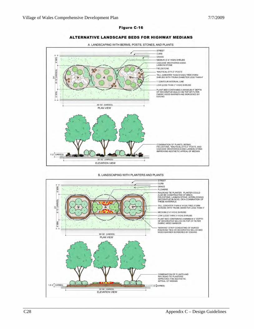
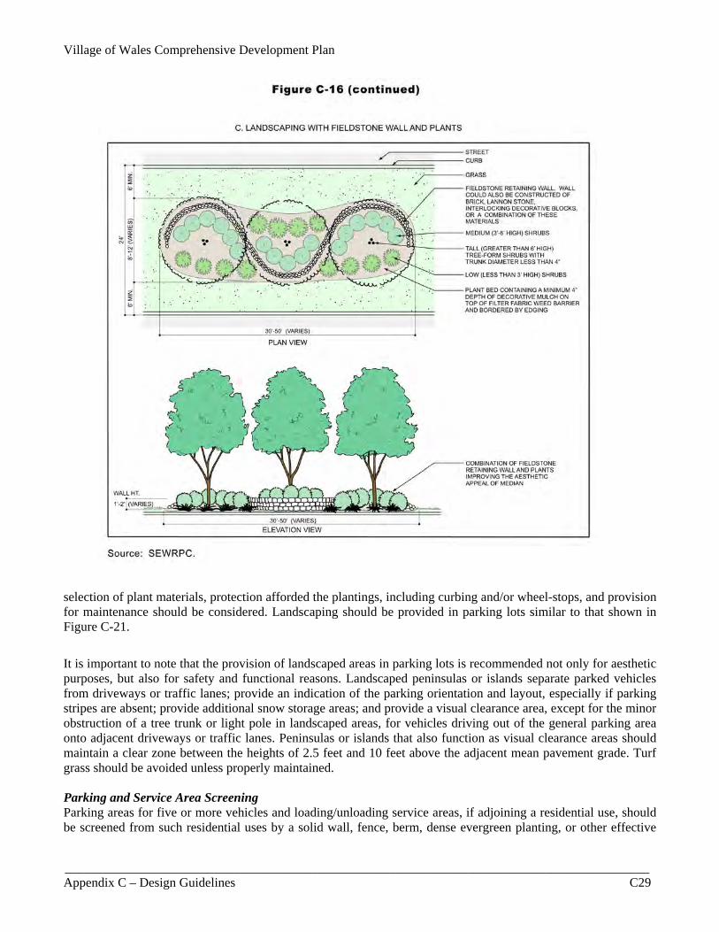
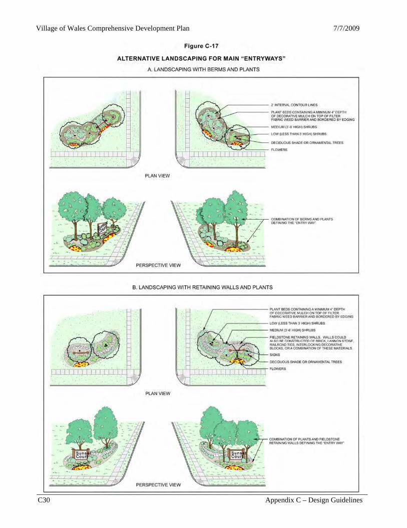
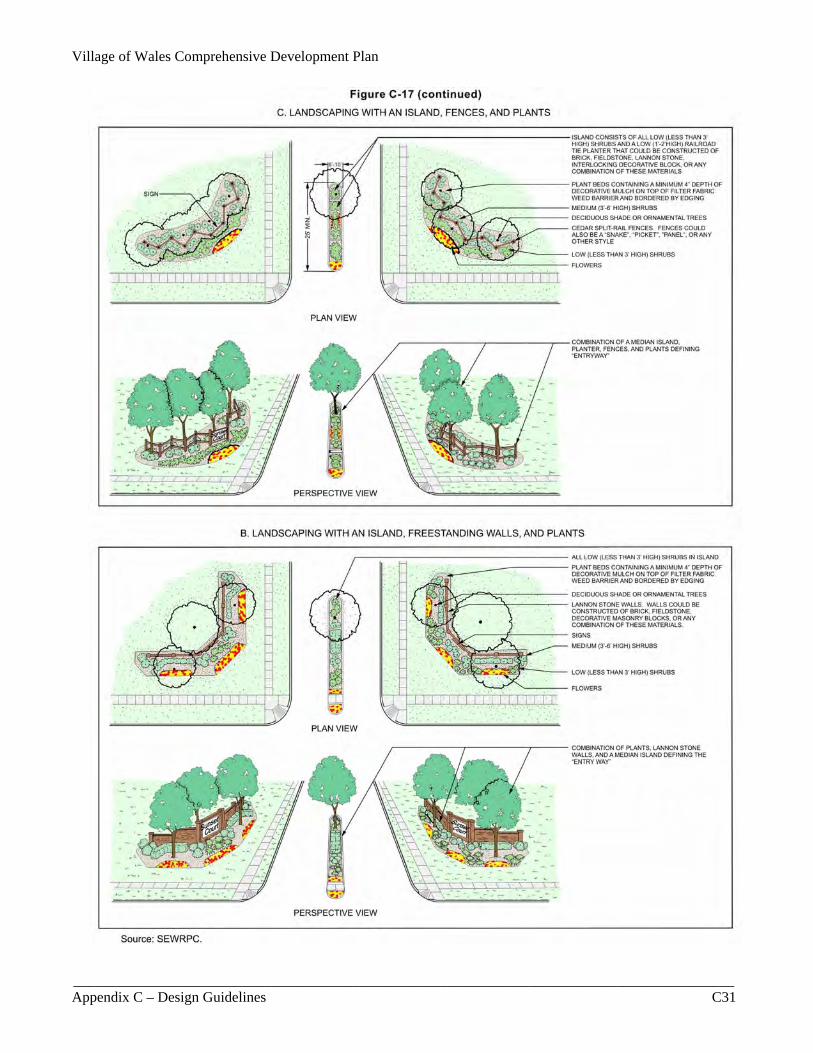
MINIMUM STREET TREE PLANTING DISTANCES IN RIGHTS-OF-WAY Source: SEWRPC. Median Landscaping While recognizing traffic visibility requirements, large elevated plant beds, such as those shown in Figure C-16, should be provided in all future street medians, especially if these streets also function as gateway thoroughfares, to dramatically improve the streetscape of the community. Streetlight poles should contain colorful banners, or at least on poles at selected locations such as median openings and/or street intersections, for aesthetic purposes and to further instill a sense of place, while observing traffic visibility requirements. Any proposed landscaping in street rights-of-way should be coordinated with the government agency that has jurisdiction. For example, landscaping in state trunk highway rights-of-way requires a permit from the Wisconsin Department of Transportation (WisDOT). WisDOT permits plants with a trunk diameter of four inches or greater in the tree banks alongside highways with low speed limits, but prohibits such plant sizes in the medians. Tall shrubs shaped into a tree form, instead of large deciduous trees, could provide some vertical accent in the highway medians, as illustrated in Figure C-16. If WisDOT was to grant a special exception to its requirement and permit plants that would grow to a trunk diameter of four inches or greater in the medians, then deciduous shade or ornamental trees could be used in lieu of the tree-form shrubs. Raised medians four feet or less in width should not be comprised of asphalt, but should contain either concrete or preferably decorative masonry, or even flowers and ornamental grasses if properly maintained. Raised channelizing islands should also consist of decorative brick and not unattractive plain asphalt, since they may serve as a safe haven for pedestrians waiting to cross busy streets. As an alternative, such medians may contain a mixed brick and concrete masonry pattern or a color-stamped concrete or asphalt pattern. “Gateway” or Main “Entryway” Landscaping Main “entryways”—sometimes referred to as “gateways”—into parks, historic districts, village centers, and business centers should be well-defined with attractive landscaping and signs to provide a sense of identity as well as direction. Collector and minor land-access streets functioning as main entrances into business centers should contain an attractive entryway that may consist of landscaped boulevard-type street entrance. Proper design and maintenance of landscaped entryways, especially those containing center landscaped islands, are crucial for retaining aesthetic appeal and function without obstructing traffic visibility or turn movements. Figure C-17 illustrates alternative landscape designs for such “entryways.” Other alternative landscaping layouts are provided

Village of Wales Comprehensive Development Plan
__________________________________________________________________________________________ Appendix C – Design Guidelines C27
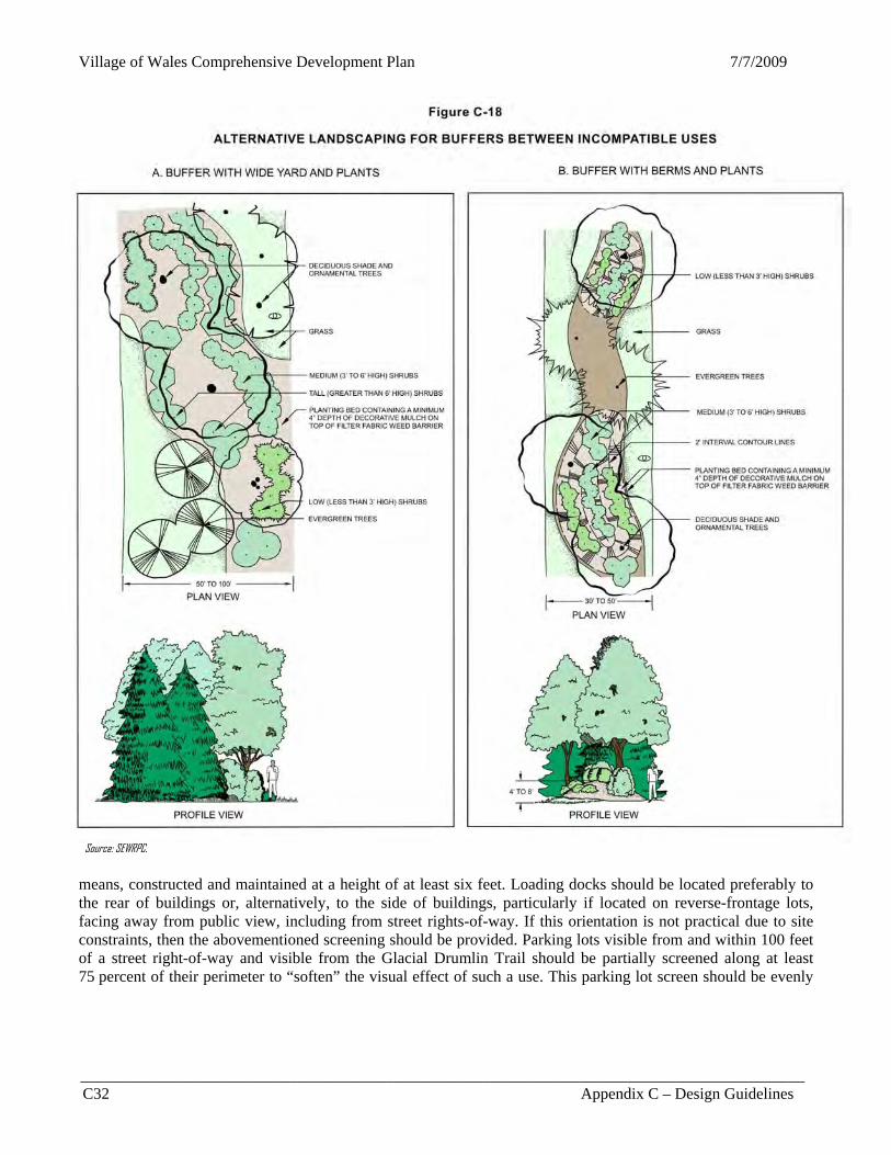
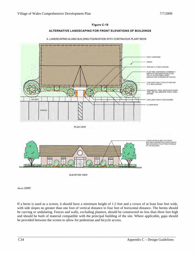
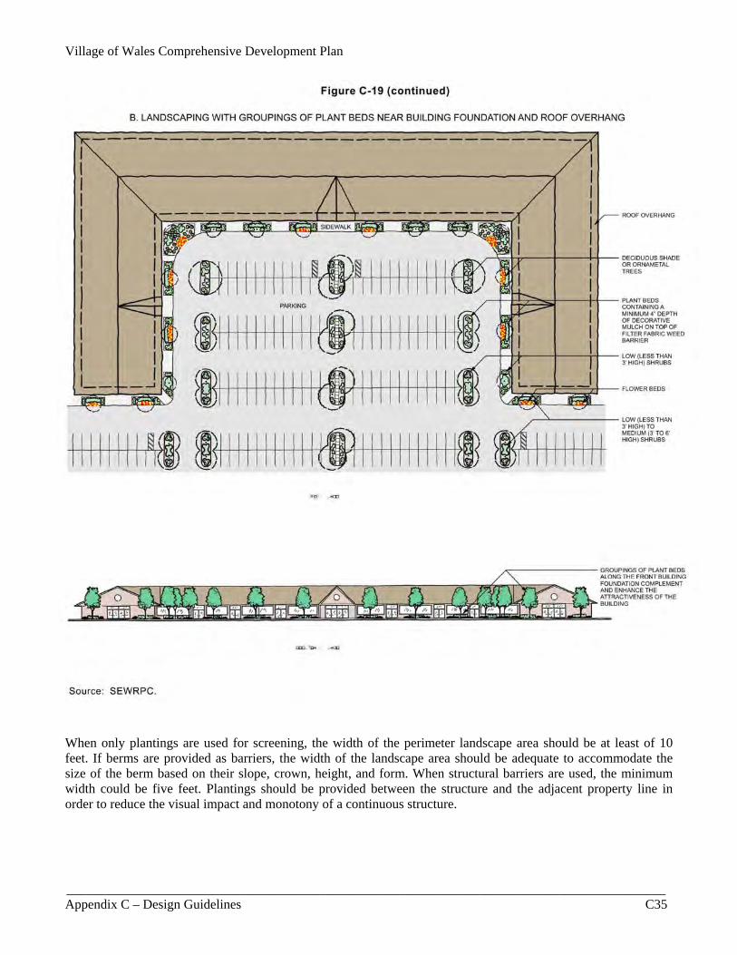
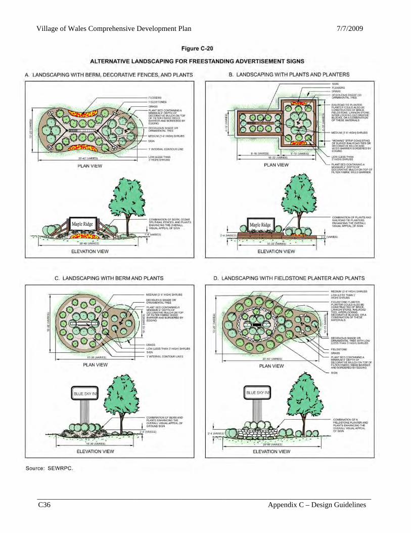
in Figure C-20. Low ground—“monument” signs—rather than high pole or pylon signs, are recommended. The Village has determined that the upkeep of most landscaped entryways, except those representing the Village as a whole such as defined “gateways,” should be primarily the responsibility of property owners or private organizations. Buffer and Perimeter Landscape Strips Perimeter landscape strips, which may also function as a landscaped buffer strip, should be located around parcels to provide open space for attractive landscaping, screening from incompatible lands uses, and filtration of stormwater runoff. These strips also help define the boundaries of properties and entrances and provide a separation between parking lots and public rights-of-way. Such strips, however, are not necessary for adjoining sites that share entrances, traffic aisles, or parking lots at the common lot line. Landscaped buffer strips, sometimes referred to as transitional yards, should be provided between incompatible uses to screen or block visual nuisances, air and noise pollutants, or other negative impacts. Buffers could consist of various landscape features such as earth berms with landscape plantings; fencing and walls with plantings; wide open spaces; and grade separations in order to effectively buffer between dissimilar uses. Landscaped buffer strips provided along public streets should be designed to ensure a desired visual character of the community. Figure C-18 illustrates alternative landscaping that could be provided in such buffer strips, including those along the rear of reverse-frontage lots. Openings for pedestrian or bicycle access should be provided, and the standards for vision triangles mentioned earlier should be recognized. Also, buffers strips should not be located on any portion of existing or dedicated rights-of-way. Building Foundation Landscaping Landscaping adjacent to building foundations contributes to the overall aesthetics of the site as well as the architectural attractiveness of a building, as graphically illustrated in Figure C-19. Landscaped areas at least five feet wide, or preferably wider, and comprised of a combination of decorative mulch, flowers, ornamental grasses, groundcover, shrubs, or trees should be provided adjacent to building elevations, excluding entrances, visible from streets and parking lots. Foundation planting beds need not be continuous nor directly against the building. Planting areas could be consolidated into large groupings of beds instead of a continuous planting strip and located at or near the dripline of roof overhangs as illustrated in Figure C-19. These planting areas could also reduce air-conditioning cost by absorbing potential refraction of warm solar radiation from adjacent pavement into buildings. Sign Landscaping A landscaped bed should be placed at the base of freestanding advertisement signs to improve the aesthetics as well as noticeability of the signs. The size of the planting area should contain a length that is at least 1.5 times the length of the sign face and a width that is at least six feet. The planting area should consist of a combination of decorative mulch, flowers, ornamental grasses, groundcover, or shrubs without obstructing the sign face, as illustrated in Figure C-20. Interior Parking Lot Landscaping For parking lots consisting of more than 20 spaces, reasonably dispersed landscaped areas should be provided within the interior of the parking lot. In general, the size of such landscaped areas should not be less than six feet wide, and no less than nine feet wide when trees are provided. At the far end of each parking bay, or row of spaces, a landscaped island of a similar dimension as a parking space should be provided to separate the bays from driveways or traffic lanes. The dimensions of a landscaped island may vary from the parking space dimension to provide desirable geometric design features, such as rounded corners and angles, to facilitate maneuvering of automobile traffic. Trees should be provided at the rate of one deciduous tree at least two inches in caliper measured 4.5 feet—about chest height—above ground for every 21 parking spaces and should be located in the landscaped areas provided within the interior of the parking lot. Location of landscaped areas,
Village of Wales Comprehensive Development Plan 7/7/2009
__________________________________________________________________________________________ C28 Appendix C – Design Guidelines
Figure C-16
ALTERNATIVE LANDSCAPE BEDS FOR HIGHWAY MEDIANS
Village of Wales Comprehensive Development Plan
__________________________________________________________________________________________ Appendix C – Design Guidelines C29
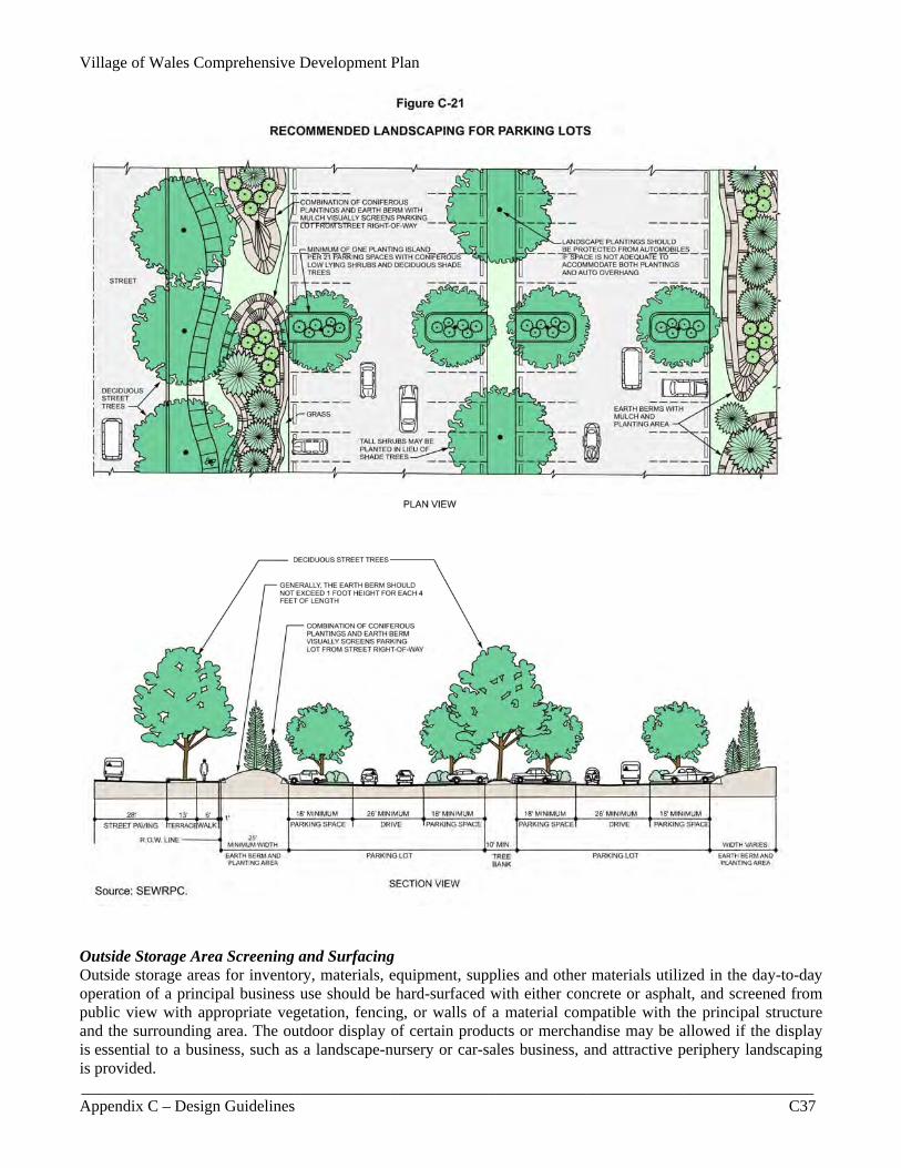
Figure C-16 (continued) Source: SEWRPC. selection of plant materials, protection afforded the plantings, including curbing and/or wheel-stops, and provision for maintenance should be considered. Landscaping should be provided in parking lots similar to that shown in Figure C-21.
It is important to note that the provision of landscaped areas in parking lots is recommended not only for aesthetic purposes, but also for safety and functional reasons. Landscaped peninsulas or islands separate parked vehicles from driveways or traffic lanes; provide an indication of the parking orientation and layout, especially if parking stripes are absent; provide additional snow storage areas; and provide a visual clearance area, except for the minor obstruction of a tree trunk or light pole in landscaped areas, for vehicles driving out of the general parking area onto adjacent driveways or traffic lanes. Peninsulas or islands that also function as visual clearance areas should maintain a clear zone between the heights of 2.5 feet and 10 feet above the adjacent mean pavement grade. Turf grass should be avoided unless properly maintained. Parking and Service Area Screening Parking areas for five or more vehicles and loading/unloading service areas, if adjoining a residential use, should be screened from such residential uses by a solid wall, fence, berm, dense evergreen planting, or other effective
Village of Wales Comprehensive Development Plan 7/7/2009
__________________________________________________________________________________________ C30 Appendix C – Design Guidelines
Figure C-17
ALTERNATIVE LANDSCAPING FOR MAIN “ENTRYWAYS”
Village of Wales Comprehensive Development Plan
__________________________________________________________________________________________ Appendix C – Design Guidelines C31
Figure C-17 (continued)
Village of Wales Comprehensive Development Plan 7/7/2009
__________________________________________________________________________________________ C32 Appendix C – Design Guidelines
Figure C-18
ALTERNATIVE LANDSCAPING FOR BUFFERS BETWEEN INCOMPATIBLE USES means, constructed and maintained at a height of at least six feet. Loading docks should be located preferably to the rear of buildings or, alternatively, to the side of buildings, particularly if located on reverse-frontage lots, facing away from public view, including from street rights-of-way. If this orientation is not practical due to site constraints, then the abovementioned screening should be provided. Parking lots visible from and within 100 feet of a street right-of-way and visible from the Glacial Drumlin Trail should be partially screened along at least 75 percent of their perimeter to “soften” the visual effect of such a use. This parking lot screen should be evenly
Source: SEWRPC.

Village of Wales Comprehensive Development Plan
__________________________________________________________________________________________ Appendix C – Design Guidelines C33
Figure C-18 (continued)
Source: SEWRPC.
distributed and could consist of a combination of plantings on top of berms or in planters, provided the combined height is at least three feet above the parking surface after three years. Figure C-6 illustrates alternative landscape screening for parking lots visible to the public. The parking lot screen may be reduced in height or eliminated if a difference in grade will screen the parking lot. Also, openings for pedestrian and bicycle access should be provided, and the standards for vision clearance triangles should be recognized.
Village of Wales Comprehensive Development Plan 7/7/2009
__________________________________________________________________________________________ C34 Appendix C – Design Guidelines
Figure C-19
ALTERNATIVE LANDSCAPING FOR FRONT ELEVATIONS OF BUILDINGS Source: SEWRPC. If a berm is used as a screen, it should have a minimum height of 1.5 feet and a crown of at least four feet wide, with side slopes no greater than one foot of vertical distance to four feet of horizontal distance. The berms should be curving or undulating. Fences and walls, excluding planters, should be constructed no less than three feet high and should be built of material compatible with the principal building of the site. Where applicable, gaps should be provided between the screen to allow for pedestrian and bicycle access.
Village of Wales Comprehensive Development Plan
__________________________________________________________________________________________ Appendix C – Design Guidelines C35
Figure C-19 (continued) Source: SEWRPC. When only plantings are used for screening, the width of the perimeter landscape area should be at least of 10 feet. If berms are provided as barriers, the width of the landscape area should be adequate to accommodate the size of the berm based on their slope, crown, height, and form. When structural barriers are used, the minimum width could be five feet. Plantings should be provided between the structure and the adjacent property line in order to reduce the visual impact and monotony of a continuous structure.
Village of Wales Comprehensive Development Plan 7/7/2009
__________________________________________________________________________________________ C36 Appendix C – Design Guidelines
Figure C-20
ALTERNATIVE LANDSCAPING FOR FREESTANDING ADVERTISEMENT SIGNS Source: SEWRPC.
Village of Wales Comprehensive Development Plan
__________________________________________________________________________________________ Appendix C – Design Guidelines C37
Figure C-21
RECOMMENDED LANDSCAPING FOR PARKING LOTS Source: SEWRPC. Outside Storage Area Screening and Surfacing Outside storage areas for inventory, materials, equipment, supplies and other materials utilized in the day-to-day operation of a principal business use should be hard-surfaced with either concrete or asphalt, and screened from public view with appropriate vegetation, fencing, or walls of a material compatible with the principal structure and the surrounding area. The outdoor display of certain products or merchandise may be allowed if the display is essential to a business, such as a landscape-nursery or car-sales business, and attractive periphery landscaping is provided.
Village of Wales Comprehensive Development Plan 7/7/2009
__________________________________________________________________________________________ C38 Appendix C – Design Guidelines
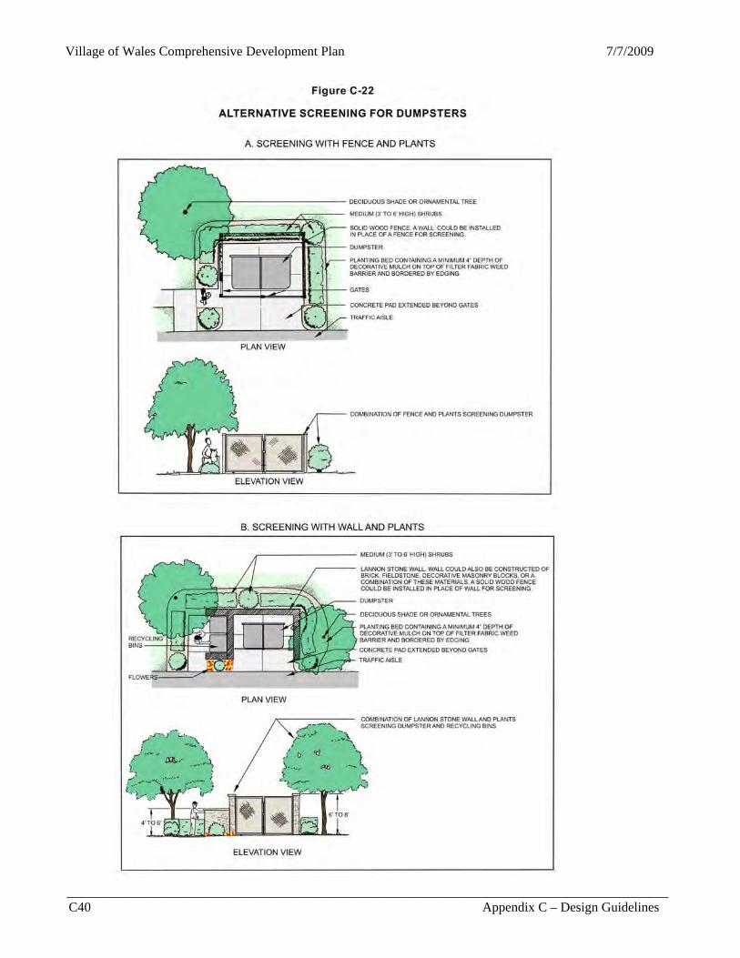
Dumpster and Mechanical Equipment Screening Dumpsters, utility boxes, and other mechanical equipment should be unobtrusive or shielded from view while still maintaining necessary access. Dumpsters should be screened, on all four sides by a solid fence or wall, from public view and adjacent properties. Dumpsters should be located preferably next to and in the rear of buildings or, alternatively, to the side and be screened with material that is identical to, or compatible with, the building. Dumpsters located near a building could utilize the building as one of the walls surrounding the dumpster. If security is a concern, the front portion or gate could consist of a partial screen with 50 percent or less opaqueness, such as a chain link gate with durable slats that are a color compatible with the rest of the screen. The height of the fence or wall should be at least one foot above the top of the dumpster to help prevent the wind from spreading debris over the structure. Plantings should also be provided adjacent to the structure in a surrounding landscape bed at least five feet wide, where adequate space is available, as shown in Figure C-22. Rooftop and at-grade mechanical equipment should also be placed in an unobtrusive location or effectively screened from public view. The screening method used should be compatible with the landscaping and building architecture of the site. Building Facades Buildings throughout the Village should contain attractive building facades, including business buildings facing public streets and parking lots. To retain or establish a unified architectural setting, building designs should be compatible with a unique style desired for a particular location or with the predominant architectural style of a defined area, such as an established residential neighborhood, a business park, a historic district, or a central business district. Nevertheless, variations of the same style should be obtained to avoid monotony. Specifically, architectural style should not be overly restricted; however, proposed buildings should be reviewed on their individual merit based upon desired building design, building materials, longevity of the color choices (fad/non-fad), statement in relation to overall design theme, compatibility with the character and color of adjacent structures, similarity between the overall size and mass of the proposed and adjacent structures, and unity with existing structures on the project site. Buildings in the Village should preferably be one to two stories in height, but no more than three stories high in order to retain a “small village character” with a human scale. To create attractive facades and some variation in architectural styles to avoid excessive repetition and drabness, emphasis should be placed on: the creation of a varied roof line on a building by using, for example, a pitched roof with dormers or multiple pediments with gables to break the roofline; use of some variation in door and window styles from small to large sizes and from square to round shapes that are still proportionate to the building mass; creation of well-defined main entryways, facade protrusions and recesses with porches and entryways, and wall offsets and recesses; use of columns, porticos, overhangs, projections, arcades, and arches; use of earth tone colors harmonious to the surrounding area and the Village as a whole, with bright colors used only for accent on trims or canopies; and mixture of attractive finished material, such as stone, brick, wood, or decorative masonry blocks. All building sides of multi-family residential, commercial, industrial, governmental, and institutional buildings should consist of such finished material. In addition, large buildings, especially “big-box” retail stores, that are devoid of any architectural character should be avoided, since they typically consist of long continuous walls without a “break”—a protrusion or recession in the wall or a change in facade style. Public entryways should be clearly defined by the use of porticos, overhangs, or projections. For residential areas, garages should be de-emphasized without changing the building architecture. The front or main elevation of buildings facing public streets should not be overly dominated by more than 50 percent by the appearance of an individual garage, especially three-car garages, or a row of garages in multi-family residential areas with the large doors facing the front and the front yards, oftentimes occupied by mostly paved driveways with little landscaping. As alternatives, three-car garages could be oriented to face the side yard, and the row of garages for multi-family residential areas could be oriented to face the side or rear yards. Rows of doors for mini-warehouse or storage facilities should also be oriented to face side or rear yards, if possible. Otherwise, such doors should be buffered from public view.
Village of Wales Comprehensive Development Plan
__________________________________________________________________________________________ Appendix C – Design Guidelines C39
Signs General In addition to conforming to the requirements of a community sign ordinance, signs should be designed to complement the overall character of the area and its buildings. Lettering on signs should be functional as well as visually pleasing. Truly functional lettering uses a typeface which is properly spaced and easy to read and makes its message clear from the distance at which it is intended to be read. Generally, the less cluttered and fewer the words on the sign face, the more likely people will be able to read the sign with ease. A master sign for developments with multiple tenants should display the owner, business, or shopping center name only, and should be used to reduce clutter by integrating existing signs and eliminating unnecessary ones; to provide a coherent sign with minimal verbiage; and to be positioned so that it would not blight the streetscape. The name of only a major anchor(s) of a shopping center should be allowed as an addition to this master sign. A permanent window sign should not occupy more than 25 percent of the pane on which it is displayed. Low ground signs—“monument” signs—of no more than four to six feet in height supported by ornate columns or pillars on the sides and/or a structural base with a width of at least 75 percent of the width of the sign face, are usually considered more attractive and desirable than high pole or pylon signs, which are discouraged. All freestanding signs should ideally be panel signs supported by structures comprised of materials similar to or compatible with the building materials of the principal structure and be surrounded by attractive landscaping at the base. Wall signs attached to buildings should not extend above any roofline nor should wall signs and projecting signs extend above second floor window sills. Overall, the sign composition, structural material, color, logo, and location should be compatible with the building architecture. Main “Entryway” and “Gateway” or Community “Welcome” Signs Main “entryways” into parks, historic village centers, and business centers should be well-defined with attractive signs to provide a sense of identity as well as direction. Community “Welcome” signs or permanent banner-type signs extending across streets should also be provided at key locations along streets functioning as main “gateways” into a community, including the Historic Village Center. The design should be representative of the character of the community and should reflect the design theme desired by the community residents. Emblems of service clubs or charitable organizations of a community that are sometimes accommodated on community welcome signs should not obstruct or overly clutter the “Welcome” sign face. As an alternative, a separate panel with an overhead title “Service Clubs of Wales” could be provided to group and arrange the small emblem signs in a presentable manner. Street and Wayfinding Signs Street signs should be located at each street intersection and should be legible for all user groups. Simple “icon” or graphic symbol signs could also be used for aesthetic as well as wayfinding purposes such as, for example, identifying a public parking lot or providing symbolic directions to a public library. Unique street name signs should be provided that are different from the traditional rectangular street blades by consisting of a blue or red background with white letters and an icon at the end that reflects the community logo or neighborhood character. Even ornate street-sign poles and distinctively shaped street signs, such as elliptical or oval shapes, could be used for unique aesthetics. Street Light and Traffic Pole Styles The traditional style of tall streetlights could be made more attractive by using colors, such as black or green, instead of the bare silver metal color. As an alternative, the poles could be colored black or green while the extended arm with the illumination head could remain silver. Low uniquely-designed street lights should preferably be installed along the “Main Street(s)” of a community. The style or color selected for street lights should be emulated in the poles of street signs and traffic signs and signals.
Village of Wales Comprehensive Development Plan 7/7/2009
__________________________________________________________________________________________ C40 Appendix C – Design Guidelines
Figure C-22
ALTERNATIVE SCREENING FOR DUMPSTERS
Village of Wales Comprehensive Development Plan
__________________________________________________________________________________________ Appendix C – Design Guidelines C41
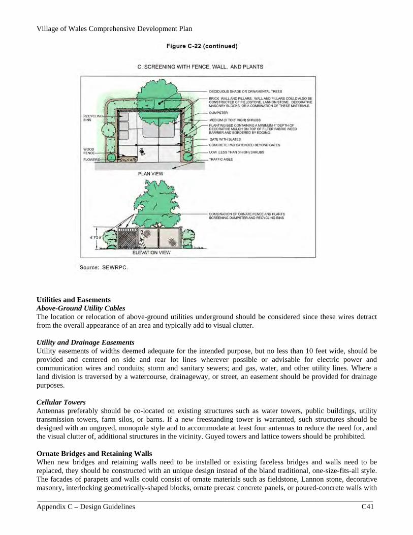
Figure C-22 (continued) Utilities and Easements Above-Ground Utility Cables The location or relocation of above-ground utilities underground should be considered since these wires detract from the overall appearance of an area and typically add to visual clutter. Utility and Drainage Easements Utility easements of widths deemed adequate for the intended purpose, but no less than 10 feet wide, should be provided and centered on side and rear lot lines wherever possible or advisable for electric power and communication wires and conduits; storm and sanitary sewers; and gas, water, and other utility lines. Where a land division is traversed by a watercourse, drainageway, or street, an easement should be provided for drainage purposes. Cellular Towers Antennas preferably should be co-located on existing structures such as water towers, public buildings, utility transmission towers, farm silos, or barns. If a new freestanding tower is warranted, such structures should be designed with an unguyed, monopole style and to accommodate at least four antennas to reduce the need for, and the visual clutter of, additional structures in the vicinity. Guyed towers and lattice towers should be prohibited. Ornate Bridges and Retaining Walls When new bridges and retaining walls need to be installed or existing faceless bridges and walls need to be replaced, they should be constructed with an unique design instead of the bland traditional, one-size-fits-all style. The facades of parapets and walls could consist of ornate materials such as fieldstone, Lannon stone, decorative masonry, interlocking geometrically-shaped blocks, ornate precast concrete panels, or poured-concrete walls with
Village of Wales Comprehensive Development Plan 7/7/2009
__________________________________________________________________________________________ C42 Appendix C – Design Guidelines
unique “color-stamped” patterns or geometric patterns defined by scorelines and “brushed” surfaces with smooth edges as opposed to plain poured-concrete surfaces. Unless a community wishes to intentionally screen motor vehicles, the parapet—low wall or railing—of bridges should be partially “open,” and yet function as a barrier for safety reasons, so that motorists can see through the parapet to enjoy the scenery from the bridge, including those over waterways. Stormwater Management Facilities Stormwater management facilities should be adequate to serve a proposed development, and may include curbs and gutters; catch basins and inlets; storm sewers; open channels; roadside swales; culverts; water detention or retention facilities; infiltration facilities; and existing natural depressions, wetlands, and streams. The facilities should be of adequate size and grade to accommodate peak rates and volumes of runoff through and from a proposed development, and should be so designed as to prevent and control nonpoint source pollution and to present no hazards to life or property. When natural features on the site are to be incorporated in the stormwater management system, appropriate measures should be implemented to avoid degrading the quality of those features. Stormwater facilities should, as a minimum, meet the storm water management requirements for the Village of Wales and the design standards established by the Wisconsin Department of Natural Resources (DNR) in a document titled, Wisconsin Storm Water Manual, Part Two: Technical Design Guidelines for Storm Water Best Management Practices. Stormwater detention or retention basins should have a 10- to 20-foot wide gently sloping “safety shelf” with a maximum depth of one foot around the perimeter and should be graded to a safe slope, no steeper than one vertical to four horizontal above the “safety shelf.” Such basins should blend into the landscape with a natural form to avoid the “ice cube tray” appearance. Erosion and Sedimentation Control Earthmoving activities, such as grading, topsoil removal, mineral extraction, road cutting, waterway construction or enlargement, excavation, channel clearing, ditching, drain tile laying, dredging, and lagooning, should be so conducted as to prevent erosion and sedimentation and to minimize disturbance to natural fauna, flora, watercourses, water regimen, and topography. Construction activities should be planned so that the soil is disturbed a minimal amount of time. In general, cut and filled lands outside street rights-of-way should be graded to a slope not exceeding 25 percent or the angle of repose of the soil, whichever is less. All erosion control measures should meet the construction site erosion control requirements for the Village of Wales and the design standards identified by the DNR in a document titled, Wisconsin Construction Site Best Management Practice Handbook. To help prevent erosion and sedimentation, a developer should plant grasses, shrubs, trees, and vines—the species and size of which should be determined based on those identified in Appendix E. The Village may require a developer to provide or install protection and other rehabilitation measures such as fencing, slopes, riprap, wells, revetments, berms, jetties, clearing, dredging, snagging, drop structures, brush mats, willow poles, and grade stabilization structures. General Maintenance A complete and thorough public maintenance program for public lands, as well as individual private maintenance programs, especially in commercial areas, should be established. Improvements to buildings and their continued positive appearance depend on proper maintenance procedures. Maintenance programs should include staking, watering, fertilizing, spraying, weeding, pruning, replacing and other general maintenance of landscape planting areas; picking up litter and emptying trash containers in a timely fashion; sweeping, cleaning, and repairing paved surfaces; and the care and maintenance of site furniture and the repair and/or replacement of nonfunctioning streetlights and fixtures and other amenities. Establishing a maintenance program will help to ensure the continued attractiveness and viability of the community.
Village of Wales Comprehensive Development Plan
__________________________________________________________________________________________ Appendix C – Design Guidelines C43
DESIGN GUIDELINES FOR THE HISTORIC VILLAGE CENTER Design Concept The Village should continue to improve the Historic Village Center, as defined on Map III-14 in Chapter III, as a vibrant, compact location of mostly residential uses mixed with limited, compatible small businesses and specialty stores while capitalizing on the popular Glacial Drumlin Trail. The Center should be designed with a human-scale focus with attractive streetscaping that complements unique buildings close to sidewalks or roads, further supporting a pedestrian- and bicycle-friendly environment. Specifically, the Center should continue to project a “small-village” setting, possibly with a Welsh or “country” design theme, with buildings continuing to reflect the predominantly residential architectural character by using peaked roofs, such as gable or hip-style roofs, complemented with building facades consisting of light-colored material, such as cream city brick, or, preferably, natural materials such as wood, fieldstone, and/or native Lannon stone. Business buildings should also be constructed with a residential architectural style with pitched roofs as opposed to incompatible boxed-shaped, concrete block structures with flat roofs that are devoid of any architectural style, as illustrated in Figure C-24. The “country” landscape design character for the Center could consist of mostly natural landscaping, low fieldstone or limestone walls, and ornate open fences—with no more than 50 percent opaqueness—such as cedar split-rail fences, white picket fences, or decorative wrought-iron fences. The character of the Historic Village Center should also continue to be defined largely by the presence of the Glacial Drumlin Trail with mostly open space between this trail and Main Street. The space on the other side of the trail and James Street could accommodate some buildings, such as narrow buildings with cedar-shingled, gable roofs over facades consisting of light, earth tone colors with fieldstone or native Lannon stone. Ideally, significant historic buildings in the surrounding “Welsh Hills” area, that otherwise may be demolished, could be relocated to this narrow strip of land to establish a historic settlement. Such a setting would not require converting as much open space or lawn to asphalt for parking purposes in comparison with that required for more intensive uses. Entryway/Gateway Identification A sense of arrival and definition to the Historic Village Center should be established at “entryways” or streets leading into the Center along with streetscape improvements, including street trees, decorative street lights, articulated crosswalks, and entrance monuments. Entrance monuments should be placed at key entryways—sometimes referred to as gateways—consisting of either permanent banner-type signs extending across streets or low monument signs made of natural stone or wood-carved material set on a decorative base, such as an ornate fieldstone or limestone wall, surrounded by attractive landscaping, as illustrated earlier in Figure C-17. Parking Lot Locations To retain a human-scale setting for the Center, parking lots in front of buildings, as shown in Figure C-24, should be avoided and preferably located in the rear yard, except for those adjacent to the Glacial Drumlin Trail which should be located in the side yard. Areas containing limited rear yard could locate parking lots in the side yard as an alternative while buildings would still be placed close to sidewalks or streets. Parking areas visible from streets and the Glacial Drumlin Trail, nevertheless, should be screened with landscaping that is consistent with the overall design theme desired for the historic Center. Building Streetscape Facades General Buildings within the Historic Village Center should contain attractive facades, including those facing the Glacial Drumlin Trail. The guidelines herein are not intended to restrict individual architectural expression, but rather to direct the expression towards a standard of quality and compatibility with neighboring historical and residential buildings and to complement and contribute to a desirable community identity for the Historic Village Center. The structural shapes of buildings, their proportions, the placement of openings such as doors and windows, the
Village of Wales Comprehensive Development Plan 7/7/2009
__________________________________________________________________________________________ C44 Appendix C – Design Guidelines
placement of signs, and various other building details all contribute to the overall streetscape appearance. Although the facades of two adjacent buildings may be distinctly different, their overall appearance can be made compatible through the proper use of these visual elements. Treatment plans for individual building facades should take into account the design character of the surrounding area and the various design guidelines developed herein to assure a degree of compatibility of architectural design with neighboring structures without being very dramatically different. In the Village Center, many of the historic building facades still retain to some degree their original architectural character. Every effort should be made to enhance or recapture the original character of those buildings pursuant to the standards promulgated by the U.S. Department of the Interior for historic preservation projects. The character projected by historic buildings in the Center should be maintained by continuing to encourage new structures to respect the form, materials, and detailing of surrounding existing historic buildings. These guidelines need not necessarily stifle creative architectural design, since new contemporary buildings should be designed for their own time while being in sync with the scale and rhythmic pattern of surrounding buildings. Two buildings could still be distinctly different yet seamlessly interrelated by using, for example, the pitched roof style of a building or group of buildings to ensure continuity of the residential architectural character while also maintaining proportional scale and mass. The arrangement of facade protrusions and recesses with porches and entryways, wall offsets and recesses, and use of columns, porticos, overhangs, projections, and arches can also help ensure compatibility between buildings, as illustrated in Figure C-23. Building Setbacks New buildings in the historic Center should be set back the same distance as the majority of the existing buildings. To retain the pedestrian-oriented Center, compatibly scaled buildings following existing setback lines will reinforce the existing character of the Center. Out-of-scale buildings, set either too close or too far off the street edge, should be discouraged, as illustrated in Figure C-24. Building setbacks from streets should be uniform, wherever possible. Such uniformity in the streetscape facade or street wall adds to pedestrian comfort by enclosing and defining the space and provides a sense of continuity to the streetscape. New buildings should be constructed to a “build-to” line to provide such continuity. Preferably such buildings should be set back at least five to 10 feet from streets or sidewalks, where present, to accommodate building foundation plantings. The build-to line in the historic Center should be established based on the existing setback distance most prevalent in the area. As an alternative to a strict build-to line, new buildings may be set back based on a “build-within” range, or a distance that equals the average setback distance of the existing buildings adjacent on each side. Another alternative is to construct a strong architectural feature, such as an ornate fence or stone wall, at the build-to line, with the building itself set somewhat further back. Typically very long gaps in the street wall should be avoided; however, such gaps are acceptable where properties abut the Glacial Drumlin Trail in order to appreciate the presence of this important amenity and complementary open space, which plays an integral part of the Center. When parking lots are located in side yards or when side yards between buildings are too wide, elements of a street wall at the build-to line should be provided, either in the form of landscaping, such as hedges or tree lines, or in the form of structural elements, such as low, ornate open-picket or wrought-iron fences and/or fieldstone or native Lannon stone walls, which would provide a “seam” to reinforce and continue the overall uniform setback. Building Scale and Mass The relative proportion, or scale, of a building in relation to its neighboring buildings, to the pedestrian or observer, and to the surrounding area should be considered when new buildings are built or when existing buildings are remodeled or altered. Visual elements that contribute to this overall scale and mass in the Historic Village Center include the visual rhythm and proportion of the elements of the building facades, the architectural detailing, the visual directional emphasis of the streetscape (which can either be horizontal or vertical), the
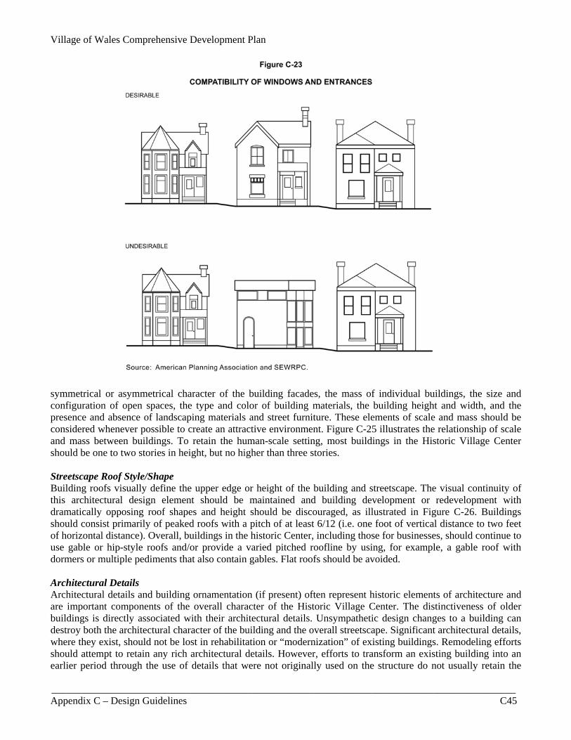
Village of Wales Comprehensive Development Plan
__________________________________________________________________________________________ Appendix C – Design Guidelines C45
Figure C-23
COMPATIBILITY OF WINDOWS AND ENTRANCES
Source: SEWRPC. symmetrical or asymmetrical character of the building facades, the mass of individual buildings, the size and configuration of open spaces, the type and color of building materials, the building height and width, and the presence and absence of landscaping materials and street furniture. These elements of scale and mass should be considered whenever possible to create an attractive environment. Figure C-25 illustrates the relationship of scale and mass between buildings. To retain the human-scale setting, most buildings in the Historic Village Center should be one to two stories in height, but no higher than three stories. Streetscape Roof Style/Shape Building roofs visually define the upper edge or height of the building and streetscape. The visual continuity of this architectural design element should be maintained and building development or redevelopment with dramatically opposing roof shapes and height should be discouraged, as illustrated in Figure C-26. Buildings should consist primarily of peaked roofs with a pitch of at least 6/12 (i.e. one foot of vertical distance to two feet of horizontal distance). Overall, buildings in the historic Center, including those for businesses, should continue to use gable or hip-style roofs and/or provide a varied pitched roofline by using, for example, a gable roof with dormers or multiple pediments that also contain gables. Flat roofs should be avoided. Architectural Details Architectural details and building ornamentation (if present) often represent historic elements of architecture and are important components of the overall character of the Historic Village Center. The distinctiveness of older buildings is directly associated with their architectural details. Unsympathetic design changes to a building can destroy both the architectural character of the building and the overall streetscape. Significant architectural details, where they exist, should not be lost in rehabilitation or “modernization” of existing buildings. Remodeling efforts should attempt to retain any rich architectural details. However, efforts to transform an existing building into an earlier period through the use of details that were not originally used on the structure do not usually retain the
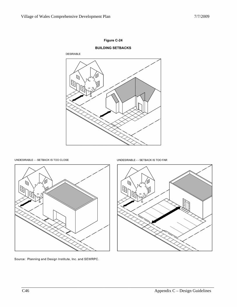
Village of Wales Comprehensive Development Plan 7/7/2009
__________________________________________________________________________________________ C46 Appendix C – Design Guidelines
Figure C-24
BUILDING SETBACKS
Source: SEWRPC.

Village of Wales Comprehensive Development Plan
__________________________________________________________________________________________ Appendix C – Design Guidelines C47
Figure C-25
URBAN SCALE AND MASS OF BUILDINGS
Source: SEWRPC. original architectural integrity of the building. Consequently, if there is an introduction of modern detail or a mixture of old and new parts on the building, the overall visual character of the building should not be destroyed, as illustrated in Figure C-27. Selection of Materials and Colors Selection of materials and colors for both architectural and landscape design should be based upon material and color unity, the atmosphere and character desired, the materials and colors composition of surrounding buildings and landscape features, the compatibility of the materials and colors used with other materials and colors, and climatic considerations. Since the primary exterior materials used in the Village Center are natural wood, stone, and brick masonry, deviation from these materials should be minimized. By using these predominant materials, the overall building facade texture of the Historic Village Center would be maintained. Overly conflicting material use and relationships should be avoided. Also, concrete block buildings, as illustrated in Figure C-24, and smooth metal-faced buildings that are devoid of any architectural prominence should be discouraged. The selection of colors for privately-owned buildings is generally an individual decision. However, the use of colors does have a significant effect upon the overall appearance of the historic Center. Colors which overwhelmingly clash with the overall visual character of the Center should be avoided. Colors should be selected to complement the colors of surrounding buildings and such natural building materials as wood, stone, and masonry. Entire color schemes should consist of mostly neutral or earth tone colors such as reds, browns, or
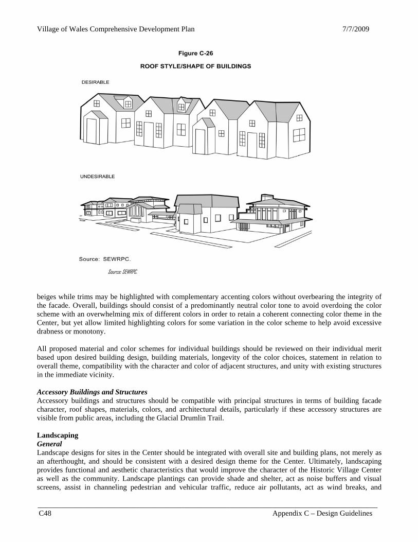
Village of Wales Comprehensive Development Plan 7/7/2009
__________________________________________________________________________________________ C48 Appendix C – Design Guidelines
Figure C-26
ROOF STYLE/SHAPE OF BUILDINGS
Source: SEWRPC. beiges while trims may be highlighted with complementary accenting colors without overbearing the integrity of the facade. Overall, buildings should consist of a predominantly neutral color tone to avoid overdoing the color scheme with an overwhelming mix of different colors in order to retain a coherent connecting color theme in the Center, but yet allow limited highlighting colors for some variation in the color scheme to help avoid excessive drabness or monotony. All proposed material and color schemes for individual buildings should be reviewed on their individual merit based upon desired building design, building materials, longevity of the color choices, statement in relation to overall theme, compatibility with the character and color of adjacent structures, and unity with existing structures in the immediate vicinity. Accessory Buildings and Structures Accessory buildings and structures should be compatible with principal structures in terms of building facade character, roof shapes, materials, colors, and architectural details, particularly if these accessory structures are visible from public areas, including the Glacial Drumlin Trail. Landscaping General Landscape designs for sites in the Center should be integrated with overall site and building plans, not merely as an afterthought, and should be consistent with a desired design theme for the Center. Ultimately, landscaping provides functional and aesthetic characteristics that would improve the character of the Historic Village Center as well as the community. Landscape plantings can provide shade and shelter, act as noise buffers and visual screens, assist in channeling pedestrian and vehicular traffic, reduce air pollutants, act as wind breaks, and
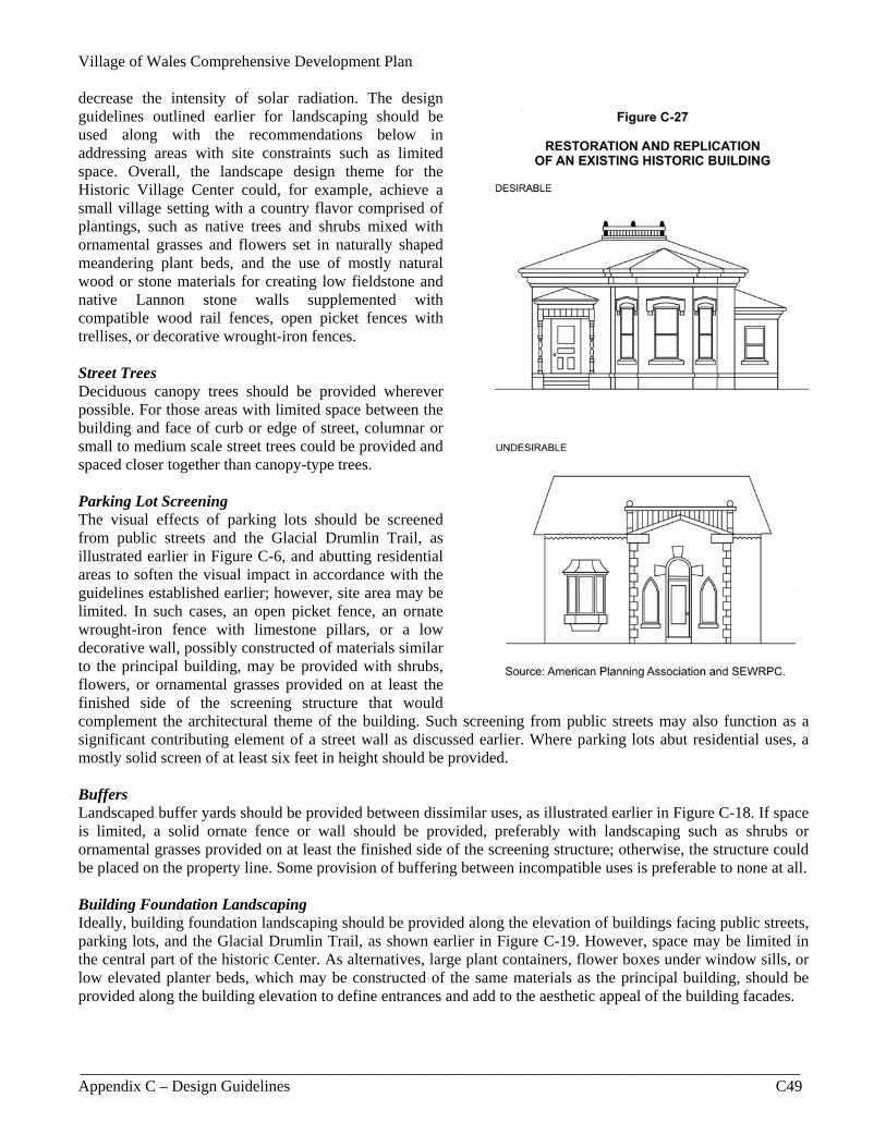
Village of Wales Comprehensive Development Plan
__________________________________________________________________________________________ Appendix C – Design Guidelines C49
decrease the intensity of solar radiation. The design guidelines outlined earlier for landscaping should be used along with the recommendations below in addressing areas with site constraints such as limited space. Overall, the landscape design theme for the Historic Village Center could, for example, achieve a small village setting with a country flavor comprised of plantings, such as native trees and shrubs mixed with ornamental grasses and flowers set in naturally shaped meandering plant beds, and the use of mostly natural wood or stone materials for creating low fieldstone and native Lannon stone walls supplemented with compatible wood rail fences, open picket fences with trellises, or decorative wrought-iron fences. Street Trees Deciduous canopy trees should be provided wherever possible. For those areas with limited space between the building and face of curb or edge of street, columnar or small to medium scale street trees could be provided and spaced closer together than canopy-type trees. Parking Lot Screening The visual effects of parking lots should be screened from public streets and the Glacial Drumlin Trail, as illustrated earlier in Figure C-6, and abutting residential areas to soften the visual impact in accordance with the guidelines established earlier; however, site area may be limited. In such cases, an open picket fence, an ornate wrought-iron fence with limestone pillars, or a low decorative wall, possibly constructed of materials similar to the principal building, may be provided with shrubs, flowers, or ornamental grasses provided on at least the finished side of the screening structure that would complement the architectural theme of the building. Such screening from public streets may also function as a significant contributing element of a street wall as discussed earlier. Where parking lots abut residential uses, a mostly solid screen of at least six feet in height should be provided. Buffers Landscaped buffer yards should be provided between dissimilar uses, as illustrated earlier in Figure C-18. If space is limited, a solid ornate fence or wall should be provided, preferably with landscaping such as shrubs or ornamental grasses provided on at least the finished side of the screening structure; otherwise, the structure could be placed on the property line. Some provision of buffering between incompatible uses is preferable to none at all. Building Foundation Landscaping Ideally, building foundation landscaping should be provided along the elevation of buildings facing public streets, parking lots, and the Glacial Drumlin Trail, as shown earlier in Figure C-19. However, space may be limited in the central part of the historic Center. As alternatives, large plant containers, flower boxes under window sills, or low elevated planter beds, which may be constructed of the same materials as the principal building, should be provided along the building elevation to define entrances and add to the aesthetic appeal of the building facades.
Village of Wales Comprehensive Development Plan 7/7/2009
__________________________________________________________________________________________ C50 Appendix C – Design Guidelines
Site Furniture and Amenities Site furniture and amenities should be provided to serve pedestrians and bicyclists while evoking a traditional, small “country” Village character. Such features include lighting standards, traffic standards, bollards, planters, benches, fences, trellises, gates, handrails, drinking fountains, water fountains, sculptures, clocks, play equipment, bike stands, garbage receptacles, kiosks, and signage. The design and arrangement of these items should contribute to the overall design theme of the Center, serving aesthetic and utilitarian functions, while adding a sense of design continuity and human scale. Above-Ground Utility Wires, Mechanical Equipment, and Dumpsters In the Historic Village Center, the relocation of above-ground utilities either underground or, if not practical, to the rear of properties, should be considered since these wires detract from the overall appearance of the Center and typically add to visual clutter. Dumpsters and mechanical equipment should be placed in an unobtrusive location and/or screened from view, as illustrated earlier in Figure C-22. If space is limited, dumpsters or mechanical equipment should be located in the rear, or, at a minimum, the structural screening shown in Figure C-2 should be provided. Rooftop and at-grade mechanical equipment should be effectively shielded from public view. Yards Front, rear, and side yards should be kept clean and proper garbage receptacles used. Other unsightly features should be covered from view in a creative fashion. Entrances for the general public should provide a walkway which exhibits safe and attractive features, including landscape plantings when practicable. Where a building site or yard is exposed to public view, consideration should be given to its urban features and to its impact on the character of the surrounding area. Street Lighting and Traffic Poles Lighting in the Historic Village Centers should relate to human scale. Primary lighting luminaries within the Historic Village Center should be mounted on uniquely designed posts at a height of generally 10 to 15 feet. This height allows the lighting to relate to both human and building scale. Lighting fixtures or luminaries should be placed so that the light overlaps at a height of about seven feet. Posts and luminaries designed with colorful banners or hanging planters should reflect the overall character desired for the Historic Village Center, such as a historic, modern, or even a mixed historic-style type of lighting with a more contemporary flair. The overall illumination should be about 2.0 footcandles. If distinctive style streetlights are not practical, the traditional style of tall streetlights could be made more attractive by using colors, such as black or green, instead of the bare metal color. As another alternative, the pole could be colored black or green while the extended arm with the illumination head could remain silver. Due to interest in conserving energy and the night sky for star gazing, street lights should be shielded to efficiently project lighting downwards without reducing the sense of security and the desired degree of illumination. Distinct design style of the streetlights should also be emulated in bollards and poles for street signs and traffic signs and signals. Signs The sign design guidelines outlined earlier under the basic urban and site planning design guidelines should be used, including the provision of graphically unique street signs and color “icon” or symbolic directional signs for wayfinding purposes. Any signs in the Historic Village Center should be placed in visually pleasing and logical places of building facades including areas that are void of openings, projections, and architectural details. Since the design concept for the historic Center is to retain a residential character, any proposed business signs should preferably be tastefully mounted flush on the building and should not extend above the first story. If projecting signs are proposed, they should not extend more than four feet beyond a building facade nor above the first story. Any proposed low monument signs should not exceed a height of about four to six feet and should be constructed of preferably natural stone or wood-carved material set on an attractive supporting base surrounded by landscaping. Tall pole and pylon signs and standard “franchise” and “brand name” signs should be avoided.