Embed Size (px)
Citation preview
NRI Grazing Land On-Site Data Collection
(03/23/20011) B-1
Appendix B
The Garmin GPS Map 76 Receiver: Features, Functions,
Setup, and Quality of Position
Garmin GPS Map76 Features Specifications
Weight: 7.5 ounces
No. channels: 12 parallel
Antenna type: Quad Helix
Display size: 180 x 240 pixels
Included map base: North America major highways, cities, exits – accepts optional
Map Source ™ enhanced maps
No. Waypoints: 500 with name and graphical symbol
No. Tracks: 10 saved, about 10,000 total track points, auto logging
No. Routes: 50 comprised of 50 waypoints each
Rugged standard: IPX 7 waterproof – floats on surface!
Other features: Trip computer, tidal info, sun/moon info, hunting/fishing info
Manual, pg. 4 and: http://www.garmin.com/products/gpsmap76/spec.html.
GPS Map 76 – Front View
Visible on the front side of the Map76 is the:
Antenna – always hold the receiver upright with the display facing you and the
antenna at about an 80 degree angle from horizontal. Face towards the southwest to
obtain the best GPS reception.
Screen protector – Provides international patent information and a reminder of how to
orient the receiver for best GPS satellite reception.
Keypad – A ROCKER key surrounded by 8 functional keys.
Display – Display capable of depicting GPS data and 4 grey color maps.
NRI Grazing Land On-Site Data Collection
(03/23/20011) B-2
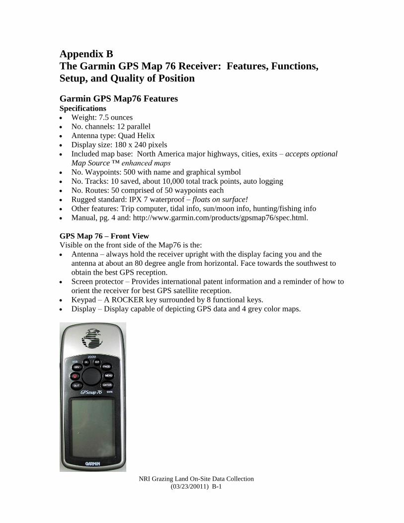
GPS Map 76 – Back View
On the back side of the Map 76 you will find: 1. The antenna port, 2. The battery
compartment, and 3. The power-data port.
You can connect an external antenna with an MCX connector to the antenna port.
NRI Grazing Land On-Site Data Collection
(03/23/20011) B-3
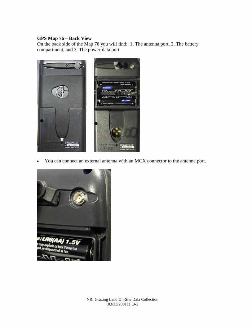
Connect the antenna by grasping the MCX connector between your thumb and index
finger and gently pushing the connector straight into the port. Remove the connector by
gently pulling it straight out. Never twist the connector while inserting it into or
removing it from the port.
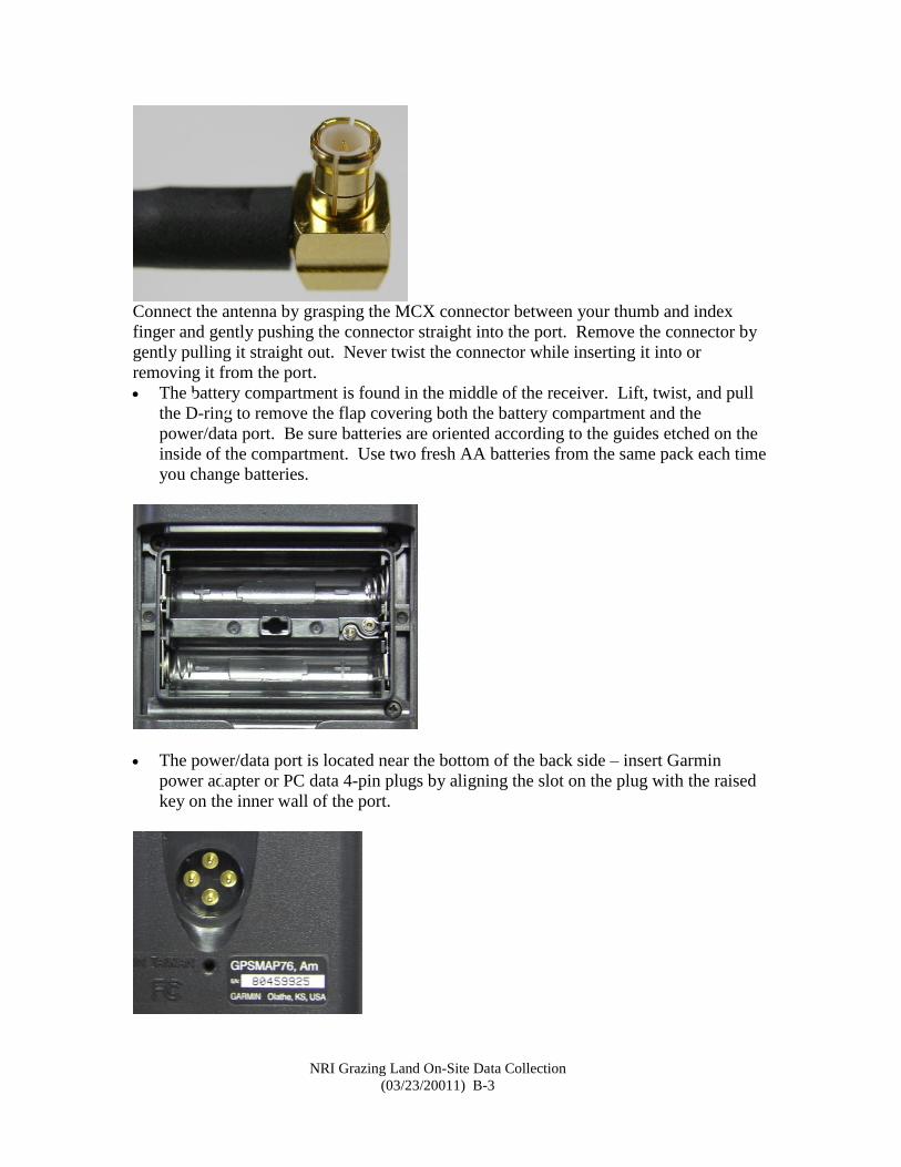
The battery compartment is found in the middle of the receiver. Lift, twist, and pull
the D-ring to remove the flap covering both the battery compartment and the
power/data port. Be sure batteries are oriented according to the guides etched on the
inside of the compartment. Use two fresh AA batteries from the same pack each time
you change batteries.
The power/data port is located near the bottom of the back side – insert Garmin
power adapter or PC data 4-pin plugs by aligning the slot on the plug with the raised
key on the inner wall of the port.
2 3
1
2
NRI Grazing Land On-Site Data Collection
(03/23/20011) B-4
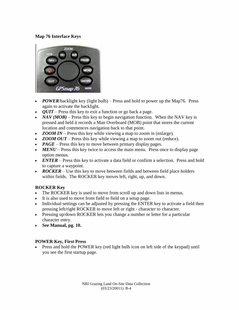
Map 76 Interface Keys
POWER/backlight key (light bulb) – Press and hold to power up the Map76. Press
again to activate the backlight.
QUIT – Press this key to exit a function or go back a page.
NAV (MOB) – Press this key to begin navigation function. When the NAV key is
pressed and held it records a Man Overboard (MOB) point that stores the current
location and commences navigation back to that point.
ZOOM IN – Press this key while viewing a map to zoom in (enlarge).
ZOOM OUT – Press this key while viewing a map to zoom out (reduce).
PAGE – Press this key to move between primary display pages.
MENU – Press this key twice to access the main menu. Press once to display page
option menus.
ENTER – Press this key to activate a data field or confirm a selection. Press and hold
to capture a waypoint.
ROCKER – Use this key to move between fields and between field place holders
within fields. The ROCKER key moves left, right, up, and down.
ROCKER Key
The ROCKER key is used to move from scroll up and down lists in menus.
It is also used to move from field to field on a setup page.
Individual settings can be adjusted by pressing the ENTER key to activate a field then
pressing left/right ROCKER to move left or right - character to character.
Pressing up/down ROCKER lets you change a number or letter for a particular
character entry.
See Manual, pg. 10.
POWER Key, First Press
Press and hold the POWER key (red light bulb icon on left side of the keypad) until
you see the first startup page.
2
3
NRI Grazing Land On-Site Data Collection
(03/23/20011) B-5
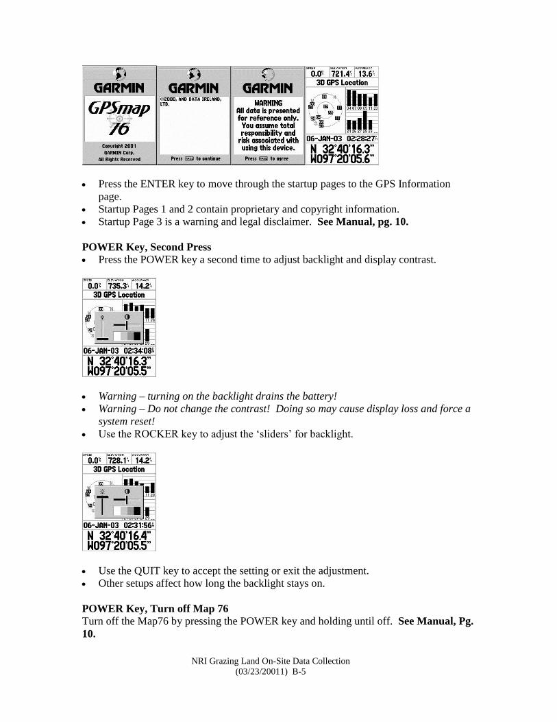
Press the ENTER key to move through the startup pages to the GPS Information
page.
Startup Pages 1 and 2 contain proprietary and copyright information.
Startup Page 3 is a warning and legal disclaimer. See Manual, pg. 10.
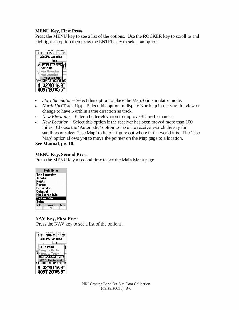
POWER Key, Second Press
Press the POWER key a second time to adjust backlight and display contrast.
Warning – turning on the backlight drains the battery!
Warning – Do not change the contrast! Doing so may cause display loss and force a
system reset!
Use the ROCKER key to adjust the ‘sliders’ for backlight.
Use the QUIT key to accept the setting or exit the adjustment.
Other setups affect how long the backlight stays on.
POWER Key, Turn off Map 76 Turn off the Map76 by pressing the POWER key and holding until off. See Manual, Pg.
10.
NRI Grazing Land On-Site Data Collection
(03/23/20011) B-6
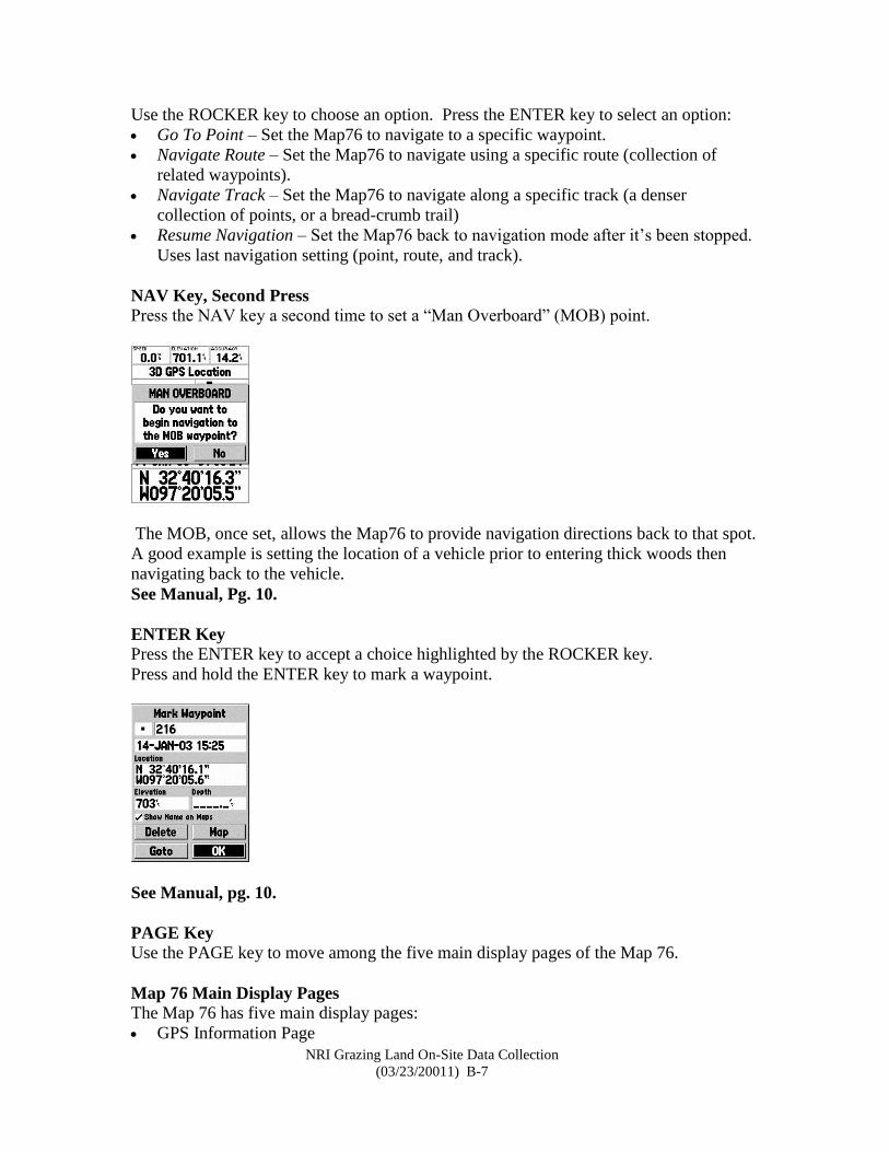
MENU Key, First Press
Press the MENU key to see a list of the options. Use the ROCKER key to scroll to and
highlight an option then press the ENTER key to select an option:
Start Simulator – Select this option to place the Map76 in simulator mode.
North Up (Track Up) – Select this option to display North up in the satellite view or
change to have North in same direction as track.
New Elevation – Enter a better elevation to improve 3D performance.
New Location – Select this option if the receiver has been moved more than 100
miles. Choose the ‘Automatic’ option to have the receiver search the sky for
satellites or select ‘Use Map’ to help it figure out where in the world it is. The ‘Use
Map’ option allows you to move the pointer on the Map page to a location.
See Manual, pg. 10.
MENU Key, Second Press
Press the MENU key a second time to see the Main Menu page.
NAV Key, First Press
Press the NAV key to see a list of the options.
3
NRI Grazing Land On-Site Data Collection
(03/23/20011) B-7
Use the ROCKER key to choose an option. Press the ENTER key to select an option:
Go To Point – Set the Map76 to navigate to a specific waypoint.
Navigate Route – Set the Map76 to navigate using a specific route (collection of
related waypoints).
Navigate Track – Set the Map76 to navigate along a specific track (a denser
collection of points, or a bread-crumb trail)
Resume Navigation – Set the Map76 back to navigation mode after it’s been stopped.
Uses last navigation setting (point, route, and track).
NAV Key, Second Press
Press the NAV key a second time to set a “Man Overboard” (MOB) point.
The MOB, once set, allows the Map76 to provide navigation directions back to that spot.
A good example is setting the location of a vehicle prior to entering thick woods then
navigating back to the vehicle.
See Manual, Pg. 10.
ENTER Key
Press the ENTER key to accept a choice highlighted by the ROCKER key.
Press and hold the ENTER key to mark a waypoint.
See Manual, pg. 10.
PAGE Key
Use the PAGE key to move among the five main display pages of the Map 76.
Map 76 Main Display Pages
The Map 76 has five main display pages:
GPS Information Page
NRI Grazing Land On-Site Data Collection
(03/23/20011) B-8
Map Page
Point Page
Highway Page
Route (or GoTo) page
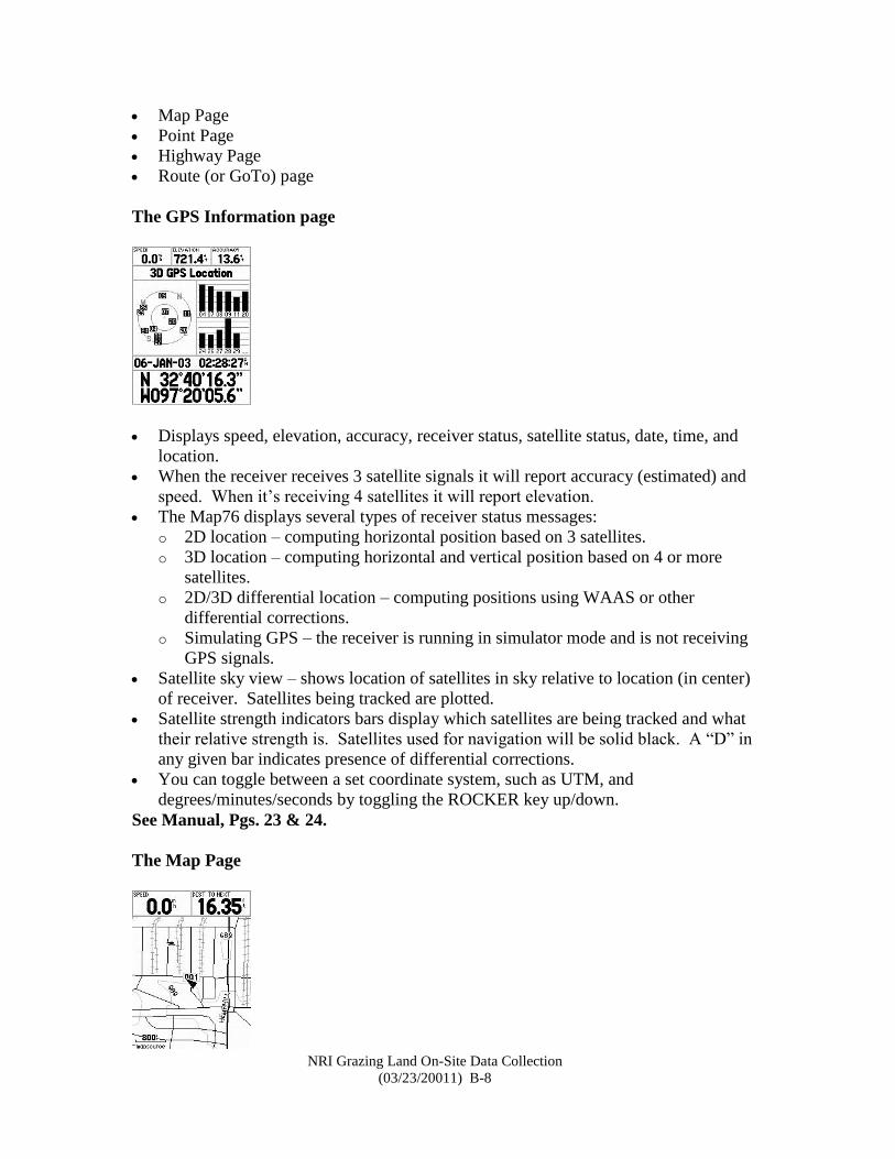
The GPS Information page
Displays speed, elevation, accuracy, receiver status, satellite status, date, time, and
location.
When the receiver receives 3 satellite signals it will report accuracy (estimated) and
speed. When it’s receiving 4 satellites it will report elevation.
The Map76 displays several types of receiver status messages:
o 2D location – computing horizontal position based on 3 satellites.
o 3D location – computing horizontal and vertical position based on 4 or more
satellites.
o 2D/3D differential location – computing positions using WAAS or other
differential corrections.
o Simulating GPS – the receiver is running in simulator mode and is not receiving
GPS signals.
Satellite sky view – shows location of satellites in sky relative to location (in center)
of receiver. Satellites being tracked are plotted.
Satellite strength indicators bars display which satellites are being tracked and what
their relative strength is. Satellites used for navigation will be solid black. A “D” in
any given bar indicates presence of differential corrections.
You can toggle between a set coordinate system, such as UTM, and
degrees/minutes/seconds by toggling the ROCKER key up/down.
See Manual, Pgs. 23 & 24.
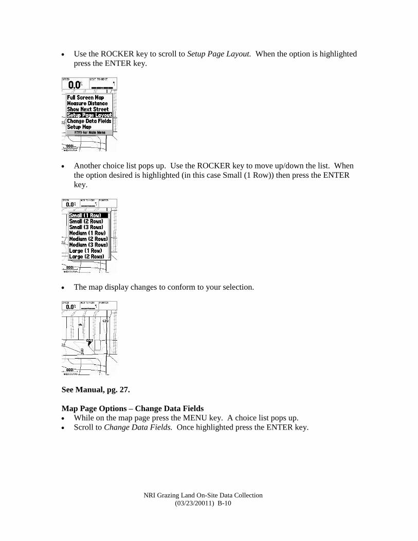
The Map Page

NRI Grazing Land On-Site Data Collection
(03/23/20011) B-9
The Map76 comes with a built-in base map of North America that includes cities,
interstate highways, and state/county roads. The scale of the map data is
approximately 1:2,000,000.
Supplemental map data can be uploaded to the Map76 from the Map Source Topo ™
software that comes with Configuration 1 & 2 systems. Map Source Topo data are
approximately 1:100,000 scale.
Other Map Source software can be obtained from Garmin or Garmin dealers:
http://www.garmin.com/cartography/mapsource/
Change the zoom scale by using the zoom keys on the Map76 keypad
o ZOOM IN
o ZOOM OUT
A scale bar is displayed in the lower left corner of the map.
If ‘Overzoom’ is displayed under the scale no further map information is available.
Map Page Zoom In/Out
Use the ZOOM IN key to zoom in on the map display. Note the scale change in the
lower left corner of the map.
Use the ZOOM OUT key to zoom out on the map display.
If ‘Overzoom’ is displayed no further map information can be displayed.
The ‘mapsource’ beneath the scale bar indicates Map Source ™ enhanced map data is
loaded and can be viewed.
See Manual, Pg. 26.
Map Page Options – Change Page Layout
Press the MENU key while on the map page
NRI Grazing Land On-Site Data Collection
(03/23/20011) B-10
Use the ROCKER key to scroll to Setup Page Layout. When the option is highlighted
press the ENTER key.
Another choice list pops up. Use the ROCKER key to move up/down the list. When
the option desired is highlighted (in this case Small (1 Row)) then press the ENTER
key.
The map display changes to conform to your selection.
See Manual, pg. 27.
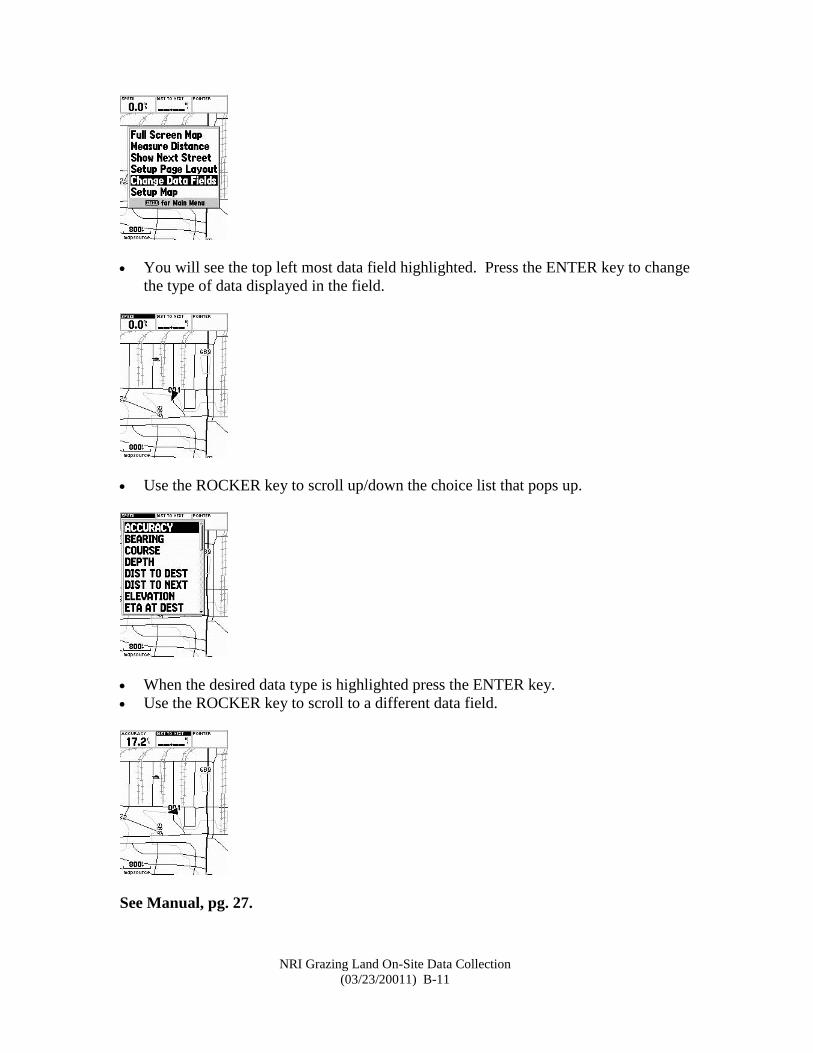
Map Page Options – Change Data Fields
While on the map page press the MENU key. A choice list pops up.
Scroll to Change Data Fields. Once highlighted press the ENTER key.
NRI Grazing Land On-Site Data Collection
(03/23/20011) B-11
You will see the top left most data field highlighted. Press the ENTER key to change
the type of data displayed in the field.
Use the ROCKER key to scroll up/down the choice list that pops up.
When the desired data type is highlighted press the ENTER key.
Use the ROCKER key to scroll to a different data field.
See Manual, pg. 27.
NRI Grazing Land On-Site Data Collection
(03/23/20011) B-12
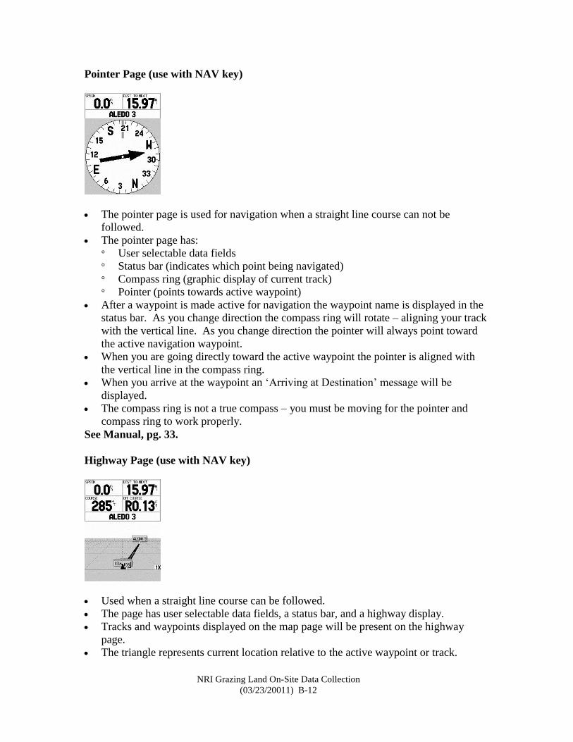
Pointer Page (use with NAV key)
The pointer page is used for navigation when a straight line course can not be
followed.
The pointer page has:
° User selectable data fields
° Status bar (indicates which point being navigated)
° Compass ring (graphic display of current track)
° Pointer (points towards active waypoint)
After a waypoint is made active for navigation the waypoint name is displayed in the
status bar. As you change direction the compass ring will rotate – aligning your track
with the vertical line. As you change direction the pointer will always point toward
the active navigation waypoint.
When you are going directly toward the active waypoint the pointer is aligned with
the vertical line in the compass ring.
When you arrive at the waypoint an ‘Arriving at Destination’ message will be
displayed.
The compass ring is not a true compass – you must be moving for the pointer and
compass ring to work properly.
See Manual, pg. 33.
Highway Page (use with NAV key)
Used when a straight line course can be followed.
The page has user selectable data fields, a status bar, and a highway display.
Tracks and waypoints displayed on the map page will be present on the highway
page.
The triangle represents current location relative to the active waypoint or track.
NRI Grazing Land On-Site Data Collection
(03/23/20011) B-13
Like the map page, the zoom level can be changed by using the ZOOM IN/OUT
keys.
Navigate down the highway by keeping the point of the triangle aligned with the
white line in the highway and the highway pointed towards the top of the display.
Press the MENU key to access the highway page options. Options are adjusted much
as they are on the map page.
See Manual, Pgs. 34-36.
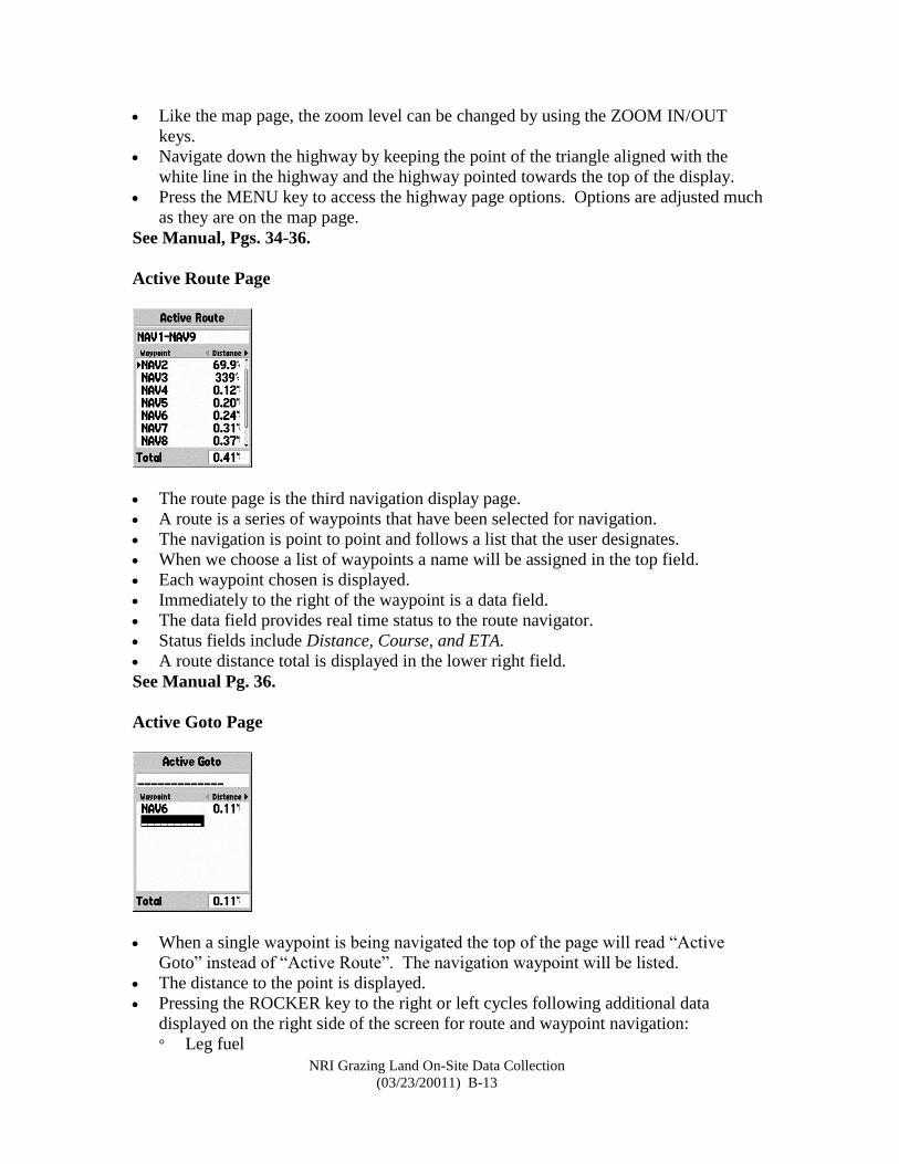
Active Route Page
The route page is the third navigation display page.
A route is a series of waypoints that have been selected for navigation.
The navigation is point to point and follows a list that the user designates.
When we choose a list of waypoints a name will be assigned in the top field.
Each waypoint chosen is displayed.
Immediately to the right of the waypoint is a data field.
The data field provides real time status to the route navigator.
Status fields include Distance, Course, and ETA.
A route distance total is displayed in the lower right field.
See Manual Pg. 36.
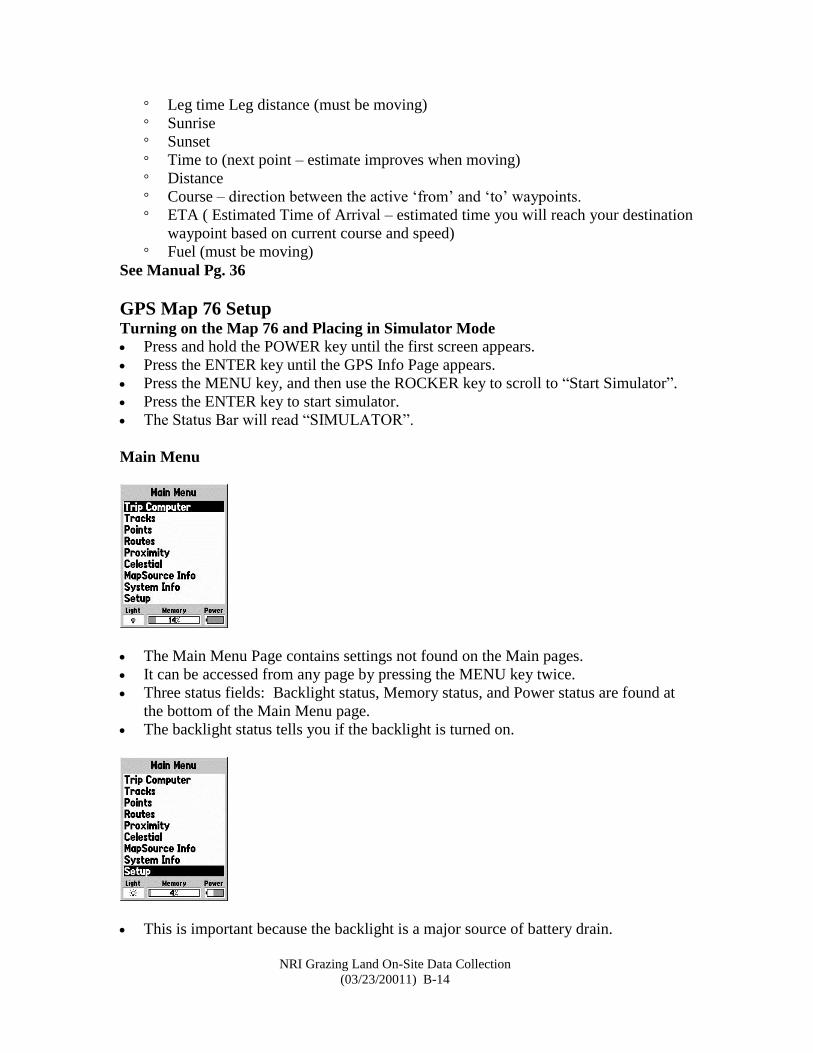
Active Goto Page
When a single waypoint is being navigated the top of the page will read “Active
Goto” instead of “Active Route”. The navigation waypoint will be listed.
The distance to the point is displayed.
Pressing the ROCKER key to the right or left cycles following additional data
displayed on the right side of the screen for route and waypoint navigation:
° Leg fuel
NRI Grazing Land On-Site Data Collection
(03/23/20011) B-14
° Leg time Leg distance (must be moving)
° Sunrise
° Sunset
° Time to (next point – estimate improves when moving)
° Distance
° Course – direction between the active ‘from’ and ‘to’ waypoints.
° ETA ( Estimated Time of Arrival – estimated time you will reach your destination
waypoint based on current course and speed)
° Fuel (must be moving)
See Manual Pg. 36
GPS Map 76 Setup Turning on the Map 76 and Placing in Simulator Mode
Press and hold the POWER key until the first screen appears.
Press the ENTER key until the GPS Info Page appears.
Press the MENU key, and then use the ROCKER key to scroll to “Start Simulator”.
Press the ENTER key to start simulator.
The Status Bar will read “SIMULATOR”.
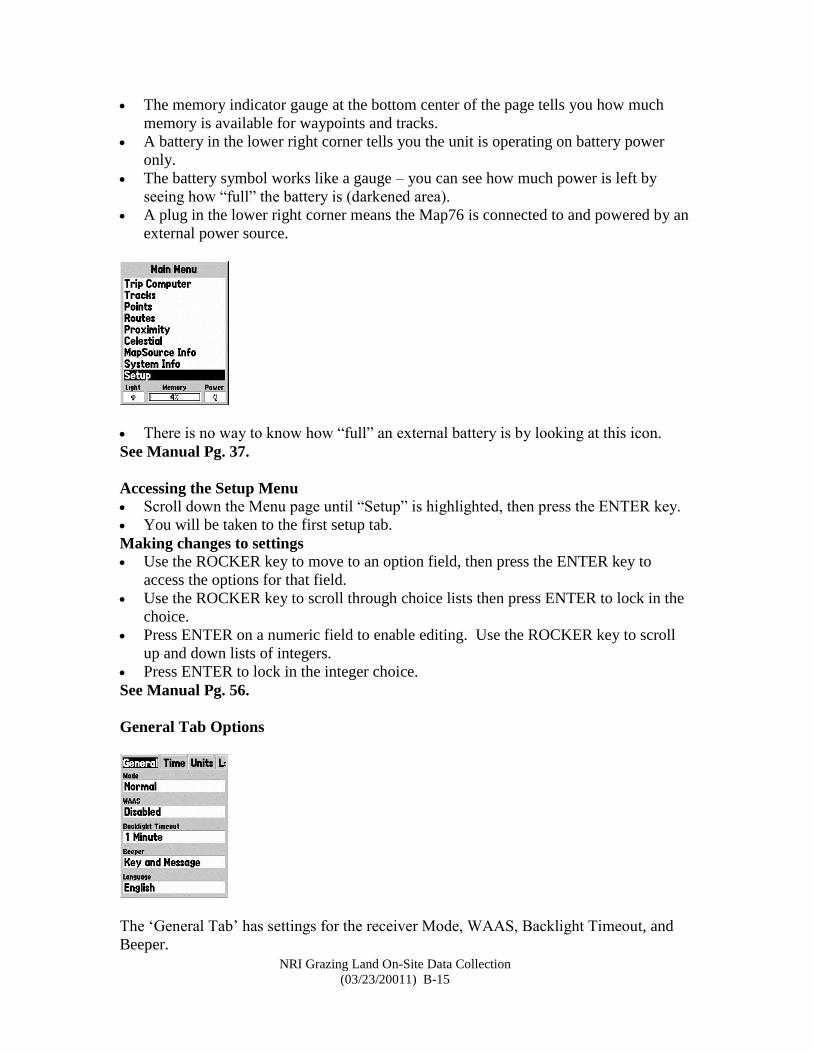
Main Menu
The Main Menu Page contains settings not found on the Main pages.
It can be accessed from any page by pressing the MENU key twice.
Three status fields: Backlight status, Memory status, and Power status are found at
the bottom of the Main Menu page.
The backlight status tells you if the backlight is turned on.
This is important because the backlight is a major source of battery drain.
NRI Grazing Land On-Site Data Collection
(03/23/20011) B-15
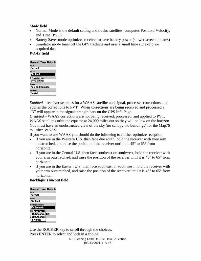
The memory indicator gauge at the bottom center of the page tells you how much
memory is available for waypoints and tracks.
A battery in the lower right corner tells you the unit is operating on battery power
only.
The battery symbol works like a gauge – you can see how much power is left by
seeing how “full” the battery is (darkened area).
A plug in the lower right corner means the Map76 is connected to and powered by an
external power source.
There is no way to know how “full” an external battery is by looking at this icon.
See Manual Pg. 37.
Accessing the Setup Menu
Scroll down the Menu page until “Setup” is highlighted, then press the ENTER key.
You will be taken to the first setup tab.
Making changes to settings
Use the ROCKER key to move to an option field, then press the ENTER key to
access the options for that field.
Use the ROCKER key to scroll through choice lists then press ENTER to lock in the
choice.
Press ENTER on a numeric field to enable editing. Use the ROCKER key to scroll
up and down lists of integers.
Press ENTER to lock in the integer choice.
See Manual Pg. 56.
General Tab Options
The ‘General Tab’ has settings for the receiver Mode, WAAS, Backlight Timeout, and
Beeper.
NRI Grazing Land On-Site Data Collection
(03/23/20011) B-16
Mode field
Normal Mode is the default setting and tracks satellites, computes Position, Velocity,
and Time (PVT).
Battery Saver mode optimizes receiver to save battery power (slower screen updates)
Simulator mode turns off the GPS tracking and uses a small time slice of prior
acquired data.
WAAS field
Enabled – receiver searches for a WAAS satellite and signal, processes corrections, and
applies the corrections to PVT. When corrections are being received and processed a
“D” will appear in the signal strength bars on the GPS Info Page.
Disabled – WAAS corrections are not being received, processed, and applied to PVT.
WAAS satellites orbit the equator at 24,000 miles out so they will be low on the horizon.
You must have an unobstructed view of the sky (no canopy, no buildings) for the Map76
to utilize WAAS.
If you want to use WAAS you should do the following to further optimize reception:
If you are in the Western U.S. then face due south, hold the receiver with your arm
outstretched, and raise the position of the receiver until it is 45° to 65° from
horizontal.
If you are in the Central U.S. then face southeast or southwest, hold the receiver with
your arm outstretched, and raise the position of the receiver until it is 45° to 65° from
horizontal.
If you are in the Eastern U.S. then face southeast or southwest, hold the receiver with
your arm outstretched, and raise the position of the receiver until it is 45° to 65° from
horizontal.
Backlight Timeout field
Use the ROCKER key to scroll through the choices.
Press ENTER to select and lock in a choice.
NRI Grazing Land On-Site Data Collection
(03/23/20011) B-17
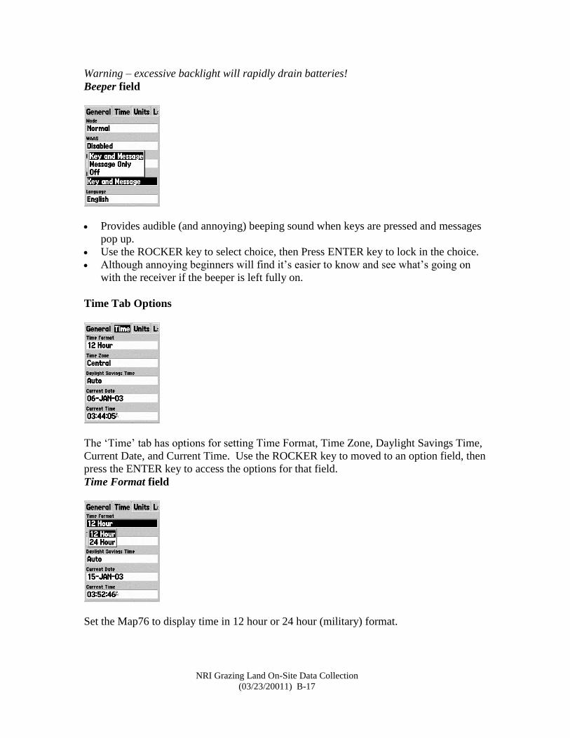
Warning – excessive backlight will rapidly drain batteries!
Beeper field
Provides audible (and annoying) beeping sound when keys are pressed and messages
pop up.
Use the ROCKER key to select choice, then Press ENTER key to lock in the choice.
Although annoying beginners will find it’s easier to know and see what’s going on
with the receiver if the beeper is left fully on.
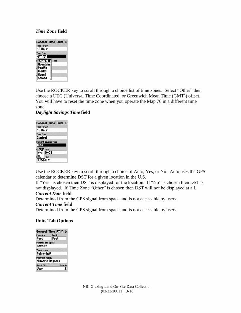
Time Tab Options
The ‘Time’ tab has options for setting Time Format, Time Zone, Daylight Savings Time,
Current Date, and Current Time. Use the ROCKER key to moved to an option field, then
press the ENTER key to access the options for that field.
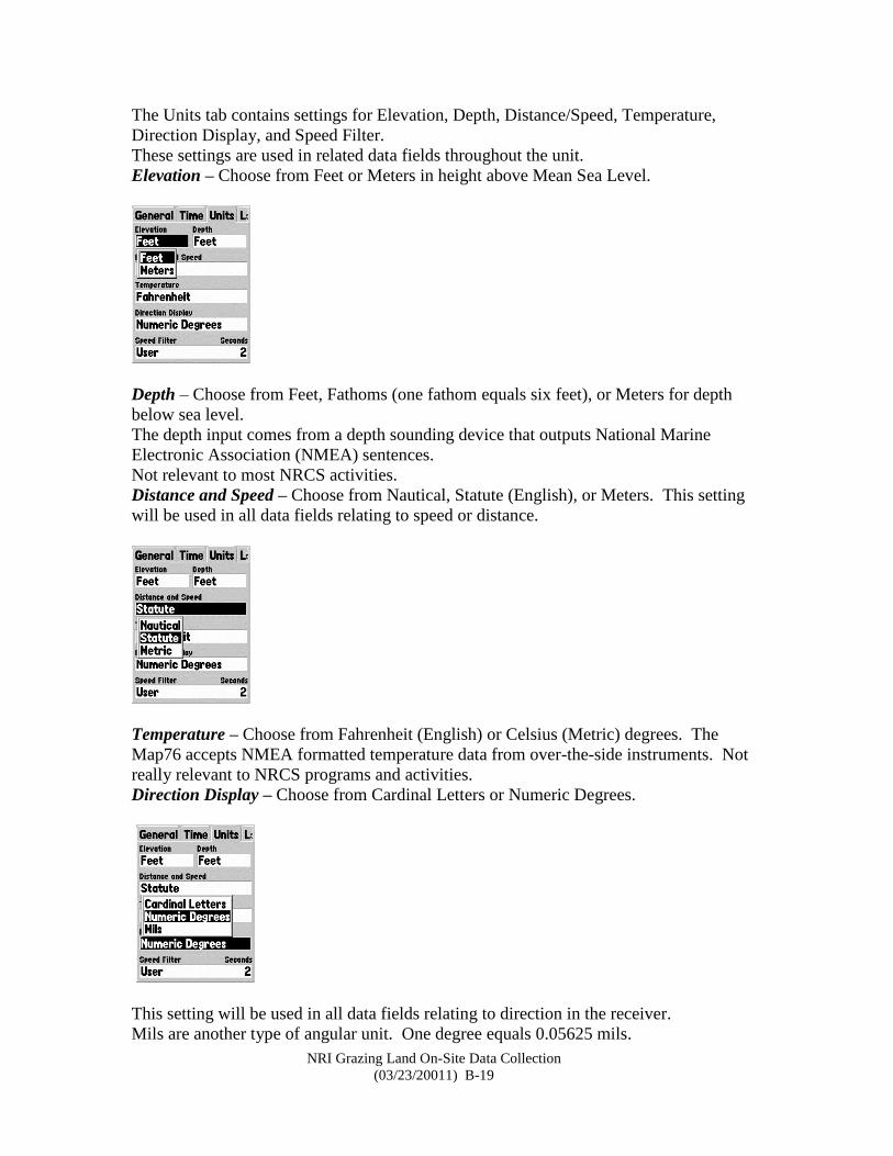
Time Format field
Set the Map76 to display time in 12 hour or 24 hour (military) format.
NRI Grazing Land On-Site Data Collection
(03/23/20011) B-18
Time Zone field
Use the ROCKER key to scroll through a choice list of time zones. Select “Other” then
choose a UTC (Universal Time Coordinated, or Greenwich Mean Time (GMT)) offset.
You will have to reset the time zone when you operate the Map 76 in a different time
zone.
Daylight Savings Time field
Use the ROCKER key to scroll through a choice of Auto, Yes, or No. Auto uses the GPS
calendar to determine DST for a given location in the U.S.
If “Yes” is chosen then DST is displayed for the location. If “No” is chosen then DST is
not displayed. If Time Zone “Other” is chosen then DST will not be displayed at all.
Current Date field
Determined from the GPS signal from space and is not accessible by users.
Current Time field
Determined from the GPS signal from space and is not accessible by users.
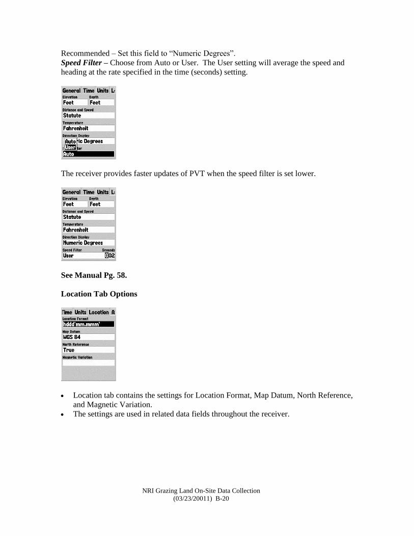
Units Tab Options
NRI Grazing Land On-Site Data Collection
(03/23/20011) B-19
The Units tab contains settings for Elevation, Depth, Distance/Speed, Temperature,
Direction Display, and Speed Filter.
These settings are used in related data fields throughout the unit.
Elevation – Choose from Feet or Meters in height above Mean Sea Level.
Depth – Choose from Feet, Fathoms (one fathom equals six feet), or Meters for depth
below sea level.
The depth input comes from a depth sounding device that outputs National Marine
Electronic Association (NMEA) sentences.
Not relevant to most NRCS activities.
Distance and Speed – Choose from Nautical, Statute (English), or Meters. This setting
will be used in all data fields relating to speed or distance.
Temperature – Choose from Fahrenheit (English) or Celsius (Metric) degrees. The
Map76 accepts NMEA formatted temperature data from over-the-side instruments. Not
really relevant to NRCS programs and activities.
Direction Display – Choose from Cardinal Letters or Numeric Degrees.
This setting will be used in all data fields relating to direction in the receiver.
Mils are another type of angular unit. One degree equals 0.05625 mils.
NRI Grazing Land On-Site Data Collection
(03/23/20011) B-20
Recommended – Set this field to “Numeric Degrees”.
Speed Filter – Choose from Auto or User. The User setting will average the speed and
heading at the rate specified in the time (seconds) setting.
The receiver provides faster updates of PVT when the speed filter is set lower.
See Manual Pg. 58.
Location Tab Options
Location tab contains the settings for Location Format, Map Datum, North Reference,
and Magnetic Variation.
The settings are used in related data fields throughout the receiver.
NRI Grazing Land On-Site Data Collection
(03/23/20011) B-21
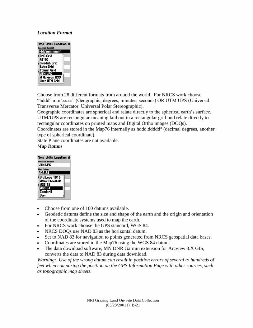
Location Format
Choose from 28 different formats from around the world. For NRCS work choose
“hddd°.mm’.ss.ss” (Geographic, degrees, minutes, seconds) OR UTM UPS (Universal
Transverse Mercator, Universal Polar Stereographic).
Geographic coordinates are spherical and relate directly to the spherical earth’s surface.
UTM/UPS are rectangular-meaning laid out in a rectangular grid-and relate directly to
rectangular coordinates on printed maps and Digital Ortho images (DOQs).
Coordinates are stored in the Map76 internally as hddd.ddddd° (decimal degrees, another
type of spherical coordinate).
State Plane coordinates are not available.
Map Datum
Choose from one of 100 datums available.
Geodetic datums define the size and shape of the earth and the origin and orientation
of the coordinate systems used to map the earth.
For NRCS work choose the GPS standard, WGS 84.
NRCS DOQs use NAD 83 as the horizontal datum.
Set to NAD 83 for navigation to points generated from NRCS geospatial data bases.
Coordinates are stored in the Map76 using the WGS 84 datum.
The data download software, MN DNR Garmin extension for Arcview 3.X GIS,
converts the data to NAD 83 during data download.
Warning: Use of the wrong datum can result in position errors of several to hundreds of
feet when comparing the position on the GPS Information Page with other sources, such
as topographic map sheets.
NRI Grazing Land On-Site Data Collection
(03/23/20011) B-22
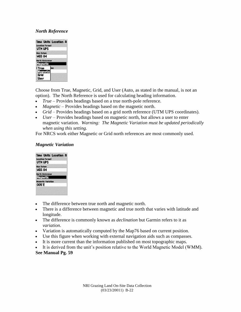
North Reference
Choose from True, Magnetic, Grid, and User (Auto, as stated in the manual, is not an
option). The North Reference is used for calculating heading information.
True – Provides headings based on a true north-pole reference.
Magnetic – Provides headings based on the magnetic north.
Grid – Provides headings based on a grid north reference (UTM UPS coordinates).
User – Provides headings based on magnetic north, but allows a user to enter
magnetic variation. Warning: The Magnetic Variation must be updated periodically
when using this setting.
For NRCS work either Magnetic or Grid north references are most commonly used.
Magnetic Variation
The difference between true north and magnetic north.
There is a difference between magnetic and true north that varies with latitude and
longitude.
The difference is commonly known as declination but Garmin refers to it as
variation.
Variation is automatically computed by the Map76 based on current position.
Use this figure when working with external navigation aids such as compasses.
It is more current than the information published on most topographic maps.
It is derived from the unit’s position relative to the World Magnetic Model (WMM).
See Manual Pg. 59
NRI Grazing Land On-Site Data Collection
(03/23/20011) B-23
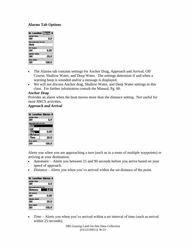
Alarms Tab Options
The Alarms tab contains settings for Anchor Drag, Approach and Arrival, Off
Course, Shallow Water, and Deep Water. The settings determine if and when a
warning beep is sounded and/or a message is displayed.
We will not discuss Anchor drag, Shallow Water, and Deep Water settings in this
class. For further information consult the Manual, Pg. 60.
Anchor Drag
Provides an alarm when the boat moves more than the distance setting. Not useful for
most NRCS activities.
Approach and Arrival
Alerts you when you are approaching a turn (such as in a route of multiple waypoints) or
arriving at your destination.
Automatic – Alerts you between 15 and 90 seconds before you arrive based on your
speed of approach.
Distance – Alerts you when you’ve arrived within the set distance of the point.
Time – Alerts you when you’ve arrived within a set interval of time (such as arrival
within 25 seconds).
NRI Grazing Land On-Site Data Collection
(03/23/20011) B-24
Off Course – Alerts you when you’ve deviated more than the set distance from your
course to your destination.
Note: 0.01 mile equals 52.8 feet. 0.03 mile equals 152.2 feet.
Shallow Water – Not useful for most NRCS activities.
Deep Water – Not useful for most NRCS activities.
Manual; Pg. 60
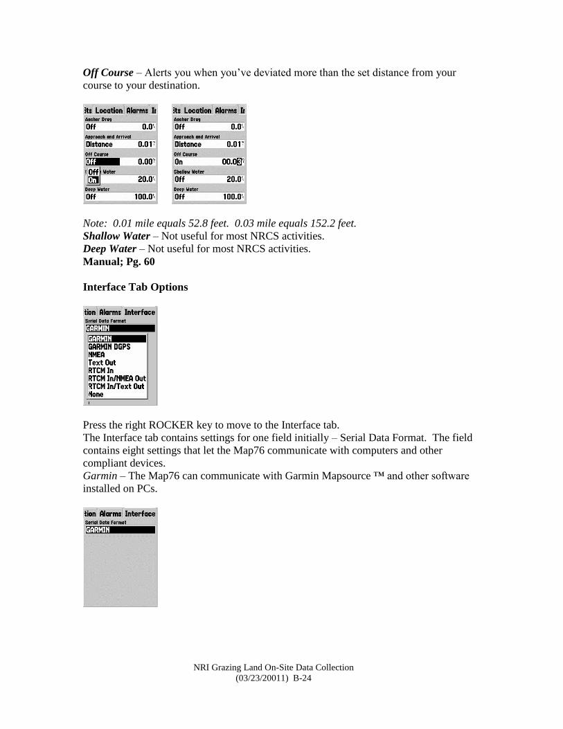
Interface Tab Options
Press the right ROCKER key to move to the Interface tab.
The Interface tab contains settings for one field initially – Serial Data Format. The field
contains eight settings that let the Map76 communicate with computers and other
compliant devices.
Garmin – The Map76 can communicate with Garmin Mapsource ™ and other software
installed on PCs.
NRI Grazing Land On-Site Data Collection
(03/23/20011) B-25
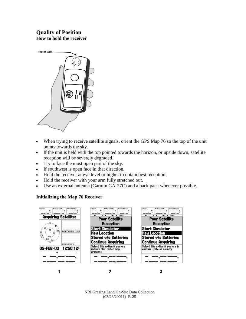
Quality of Position How to hold the receiver
When trying to receive satellite signals, orient the GPS Map 76 so the top of the unit
points towards the sky.
If the unit is held with the top pointed towards the horizon, or upside down, satellite
reception will be severely degraded.
Try to face the most open part of the sky.
If southwest is open face in that direction.
Hold the receiver at eye level or higher to obtain best reception.
Hold the receiver with your arm fully stretched out.
Use an external antenna (Garmin GA-27C) and a back pack whenever possible.
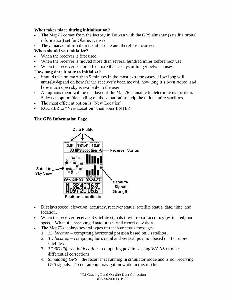
Initializing the Map 76 Receiver
NRI Grazing Land On-Site Data Collection
(03/23/20011) B-26
What takes place during initialization?
The Map76 comes from the factory in Taiwan with the GPS almanac (satellite orbital
information) set for Olathe, Kansas.
The almanac information is out of date and therefore incorrect.
When should you initialize?
When the receiver is first used.
When the receiver is moved more than several hundred miles before next use.
When the receiver is stored for more than 7 days or longer between uses.
How long does it take to initialize?
Should take no more than 5 minutes in the most extreme cases. How long will
entirely depend on how far the receiver’s been moved, how long it’s been stored, and
how much open sky is available to the user.
An options menu will be displayed if the Map76 is unable to determine its location.
Select an option (depending on the situation) to help the unit acquire satellites.
The most efficient option is “New Location”.
ROCKER to “New Location” then press ENTER.
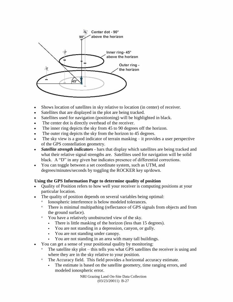
The GPS Information Page
Displays speed, elevation, accuracy, receiver status, satellite status, date, time, and
location.
When the receiver receives 3 satellite signals it will report accuracy (estimated) and
speed. When it’s receiving 4 satellites it will report elevation.
The Map76 displays several types of receiver status messages:
1. 2D location – computing horizontal position based on 3 satellites.
2. 3D location – computing horizontal and vertical position based on 4 or more
satellites.
3. 2D/3D differential location – computing positions using WAAS or other
differential corrections.
4. Simulating GPS – the receiver is running in simulator mode and is not receiving
GPS signals. Do not attempt navigation while in this mode.
NRI Grazing Land On-Site Data Collection
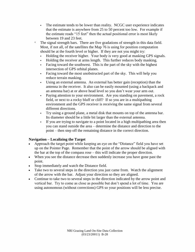
(03/23/20011) B-27
Shows location of satellites in sky relative to location (in center) of receiver.
Satellites that are displayed in the plot are being tracked.
Satellites used for navigation (positioning) will be highlighted in black.
The center dot is directly overhead of the receiver.
The inner ring depicts the sky from 45 to 90 degrees off the horizon.
The outer ring depicts the sky from the horizon to 45 degrees.
The sky view is a good indicator of terrain masking – it provides a user perspective
of the GPS constellation geometry.
Satellite strength indicators - bars that display which satellites are being tracked and
what their relative signal strengths are. Satellites used for navigation will be solid
black. A “D” in any given bar indicates presence of differential corrections.
You can toggle between a set coordinate system, such as UTM, and
degrees/minutes/seconds by toggling the ROCKER key up/down.
Using the GPS Information Page to determine quality of position
Quality of Position refers to how well your receiver is computing positions at your
particular location.
The quality of position depends on several variables being optimal:
° Ionospheric interference is below modeled tolerances.
° There is minimal multipathing (reflectance of GPS signals from objects and from
the ground surface).
° You have a relatively unobstructed view of the sky.
There is little masking of the horizon (less than 15 degrees).
You are not standing in a depression, canyon, or gully.
You are not standing under canopy.
You are not standing in an area with many tall buildings.
You can get a sense of your positional quality by monitoring:
° The satellite sky plot – this tells you what GPS satellites the receiver is using and
where they are in the sky relative to your position.
° The Accuracy field. This field provides a horizontal accuracy estimate.
The estimate is based on the satellite geometry, time ranging errors, and
modeled ionospheric error.
NRI Grazing Land On-Site Data Collection
(03/23/20011) B-28
The estimate tends to be lower than reality. NCGC user experience indicates
that the estimate is anywhere from 25 to 50 percent too low. For example if
the estimate reads “15 feet” then the actual positional error is most likely
between 19 and 23 feet.
° The signal strength bars. There are five gradations of strength in this data field.
Most, if not all, of the satellites the Map 76 is using for position computation
should be at the fourth level or higher. If they are not you might try:
Holding the receiver higher. Your body is very good at masking GPS signals.
Holding the receiver at arms length. This further reduces body masking.
Facing toward the southwest. This is the part of the sky with the highest
intersection of GPS orbital planes.
Facing toward the most unobstructed part of the sky. This will help you
reduce terrain masking.
Using an external antenna. An external has better gain (reception) than the
antenna in the receiver. It also can be easily mounted (using a backpack and
an antenna bar) at or above head level so you don’t wear your arm out.
Paying attention to your environment. Are you standing on pavement, a rock
field, or next to a rocky bluff or cliff? If so you are in a multipathing
environment and the GPS receiver is receiving the same signal from several
different directions.
Try using a ground plane, a metal disk that mounts on top of the antenna bar.
Its diameter should be a little bit larger than the external antenna.
If you are trying to navigate to a point located in a high multipathing area then
you can stand outside the area – determine the distance and direction to the
point – then step off the remaining distance in the correct direction.
Navigation – Localizing the Target
Approach the target point while keeping an eye on the “Distance” field you have set
up on the Pointer Page. Remember that the point of the arrow should be aligned with
the bar at the top of the compass rose – this will indicate the proper direction.
When you see the distance decrease then suddenly increase you have gone past the
point.
Stop immediately and watch the Distance field.
Take two to several steps in the direction you just came from. Watch the alignment
of the arrow with the bar. Adjust your direction so they are aligned.
Continue to take two to several steps in the direction indicated by the arrow point and
vertical bar. Try to come as close as possible but don’t spend a lot of time. You are
using autonomous (without corrections) GPS so your positions will be less precise.