Embed Size (px)
Citation preview

APPENDIX 6ARROW LNG PLANT
Stormwater Quality Impact Assessment

FINAL REPORT:
Arrow LNG Plant
Input to the Environmental Impact Statement
ARROW LNG PLANT STORMWATER QUALITY IMPACT ASSESSMENT
October 2011
Document history
Revision: Revision no. 06 Author/s Cleven, S. Ivezich, M. Moar, D. Checked Francey, M. Approved Cleven, S. Distribution: Revision no. 01 Issue date 16/03/2011 Issued to Arrow CSG (Australia) Pty Ltd
and Coffey Environments Australia Pty Ltd
Description: Draft for comment, do not cite. Revision no. 02 Issue date 13/05/2011 Issued to Arrow CSG (Australia) Pty Ltd
and Coffey Environments Australia Pty Ltd
Description: Draft for comment, do not cite. Revision no. 03 Issue date 01/06/2011 Issued to Arrow CSG (Australia) Pty Ltd
and Coffey Environments Australia Pty Ltd
Description: Final Revision no. 04 Issue date 02/08/2011 Issued to Arrow CSG (Australia) Pty Ltd
and Coffey Environments Australia Pty Ltd
Description: Final Revision no. 05 Issue date 22/09/2011 Issued to Arrow CSG (Australia) Pty Ltd
and Coffey Environments Australia Pty Ltd
Description: Final Revision no. 06 Issue date 10/10/2011 Issued to Arrow CSG (Australia) Pty Ltd
and Coffey Environments Australia Pty Ltd
Citation: Please cite this document as: Alluvium (2011). Arrow LNG Plant – Input to the Environmental Impact Statement: LNG Plant Stormwater Quality Impact Assessment. Report RO1 by Alluvium for Arrow CSG (Australia) Pty Ltd and Coffey Environments Australia Pty Ltd, Brisbane
Ref: \\Server1\work\Projects\2011\005_Curtis_Island_WQ\1_Deliverables\110705_LNG_Water Quality Stormwater - Arrow cosolidated comments to Coffey_v2_CN.docx
Arrow LNG Plant - Input to the EIS - STORMWATER QUALITY IMPACT ASSESSMENT i
Contents 1 Introduction 1
1.1 Project description 1
2 Background 1
2.1 Location 1
2.2 Environmental values 1
2.3 Stormwater impacts 2
3 Legislative framework 3
3.1 Water quality objectives 3
4 Conceptual stormwater quality treatment arrangement 5
4.1 Construction phase 5 Concept sizing of TSBs for construction phase 5
4.2 Operational Phase 6 Music modelling 6 Drainage and water quality arrangement 7 Vegetated Swales 7 Wetlands 8
4.3 Water quality performance 8
4.4 Decommissioning phase 8
5 Maintenance 9
5.1 Construction Phase 9
5.2 Operational and Decommission Phases 9 Establishment phase (first two years) 9 Ongoing maintenance (3 monthly interval) 10
5.3 Monitoring 10
6 Conclusion 11
7 References 11
Attachment A Stormwater Treatment System Arrangement 12
Attachment B Arrow LNG Plant ToR Cross-reference Table 16
Figures Figure 1. Proposed stormwater treatment system arrangement – mainland (construction phase) 13
Figure 2. Proposed stormwater treatment system arrangement LNG plant (construction phase) 14
Figure 3. Proposed stormwater treatment system arrangement (operational phase) 15
Tables Table 1. EPP Water environmental values 2
Table 2. Summary of relevant policy, legislation and guidelines 3
Table 3. LNG plant specific receiving waterbody objectives 4
Table 4. Proposed Sizing of temporary sediment basins for construction phase 6
Table 5. MUSIC model stormwater quality parameters 7
Table 6. Predicted operation phase stormwater quality determined using MUSIC model 8
Table 7. Generic performance criteria, standards and monitoring requirements 10

Arrow LNG Plant - Input to the EIS - STORMWATER QUALITY IMPACT ASSESSMENT 1
1 Introduction
Alluvium Consulting (Alluvium) has been engaged by Arrow CSG (Australia) Pty Ltd (Arrow Energy) and Coffey Environments Australia Pty Ltd (Coffey) to investigate the impact of the proposed Arrow LNG Plant on stormwater quality. This report outlines the potential impacts of the proposed LNG plant on stormwater quality and provides conceptual level construction, operational and decommissioning stormwater quality treatment arrangements for input into the Environmental Impact Statement for the Arrow LNG Plant.
This report has been developed in accordance with the terms of reference for the Shell Australia LNG Project (now Arrow LNG Plant) prepared by DERM that are relevant to stormwater quality management. Cross references to appropriate sections within this document are provided are provided in Appendix B.
The stormwater drainage network including internal and external drainage arrangements does not form part of this study and is to be further developed during the detailed design.
1.1 Project description The Arrow LNG Plant, formerly the Shell Australia LNG project, involves the development of a Liquefied Natural Gas (LNG) export facility on Curtis Island on the central Queensland coast, adjacent to Gladstone.
This report outlines the assessment of stormwater runoff on the LNG plant site, two temporary workers accommodation facilities (TWAFs), tunnel entry and launch sites and the potential impacts on the surrounding environment and concept level stormwater quality treatment arrangement to mitigate the impacts. Impacts on the receiving freshwater environment, including strategies to avoid, minimise, mitigate or offset potential impacts on freshwater aquatic ecosystems within or adjacent to the study area are covered in the Freshwater Ecology and Water Quality Impact Assessment (Aquateco. 2011).
2 Background
2.1 Location
Curtis Island is located between Rockhampton and Gladstone on Queensland’s central coast, covering 57,000 ha. Approximately 2.5% of the island has been designated Curtis Island Industry Precinct for LNG development and 8% allocated to conservation through the designation of the Environmental Management Precinct, which forms part of the Gladstone State Development Area. Arrow Energy has been granted an exclusive right by Gladstone Ports Corporation to investigate the development of an LNG plant located on the southern end of Curtis Island, approximately 6 km north of Gladstone. It is located outside the Great Barrier Reef Marine Park but within the Great Barrier Reef World Heritage Area, which extends to the mainland low water mark of the Queensland coast.
2.2 Environmental values In 2009 the Environmental Protection (Water) Policy was established to achieve the objectives of the Environmental Protection Act 1994 in relation to Queensland waters. This policy provides the framework for establishing environmental values and water quality objectives for Queensland waters and in particular for Port Curtis.
The objectives under the Environmental Protection (Water) Policy (2009) outline the values of aquatic ecosystems and waterways that need to be protected from the effects of catchment urbanisation and industrial development, to ensure healthy aquatic ecosystems and waterways are protected and enhanced where applicable.
The environmental values scheduled under the Environmental Protection (Water) Policy (2009) and the respective environmental values applicable to Port Curtis are listed in Table 1.
Arrow LNG Plant - Input to the EIS - STORMWATER QUALITY IMPACT ASSESSMENT 2
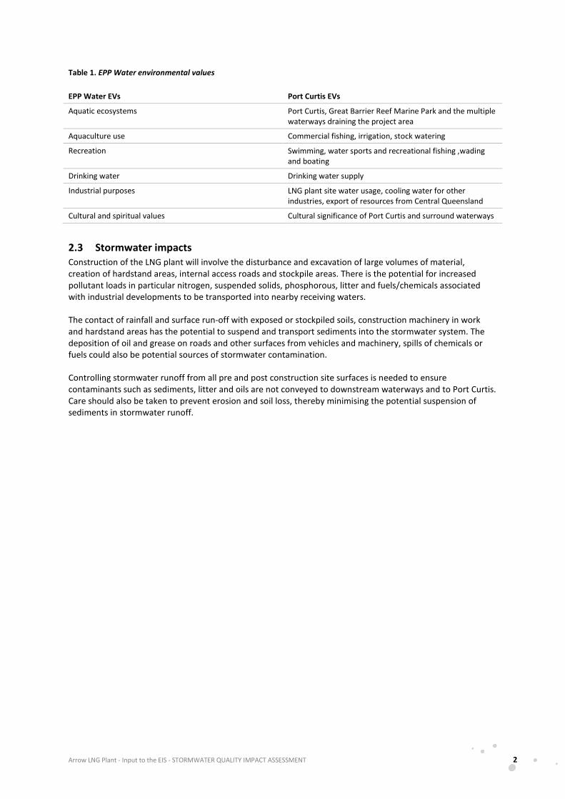
Table 1. EPP Water environmental values
EPP Water EVs Port Curtis EVs
Aquatic ecosystems Port Curtis, Great Barrier Reef Marine Park and the multiple waterways draining the project area
Aquaculture use Commercial fishing, irrigation, stock watering
Recreation Swimming, water sports and recreational fishing ,wading and boating
Drinking water Drinking water supply
Industrial purposes LNG plant site water usage, cooling water for other industries, export of resources from Central Queensland
Cultural and spiritual values Cultural significance of Port Curtis and surround waterways
2.3 Stormwater impacts Construction of the LNG plant will involve the disturbance and excavation of large volumes of material, creation of hardstand areas, internal access roads and stockpile areas. There is the potential for increased pollutant loads in particular nitrogen, suspended solids, phosphorous, litter and fuels/chemicals associated with industrial developments to be transported into nearby receiving waters.
The contact of rainfall and surface run-off with exposed or stockpiled soils, construction machinery in work and hardstand areas has the potential to suspend and transport sediments into the stormwater system. The deposition of oil and grease on roads and other surfaces from vehicles and machinery, spills of chemicals or fuels could also be potential sources of stormwater contamination.
Controlling stormwater runoff from all pre and post construction site surfaces is needed to ensure contaminants such as sediments, litter and oils are not conveyed to downstream waterways and to Port Curtis. Care should also be taken to prevent erosion and soil loss, thereby minimising the potential suspension of sediments in stormwater runoff.
Arrow LNG Plant - Input to the EIS - STORMWATER QUALITY IMPACT ASSESSMENT 3
3 Legislative framework
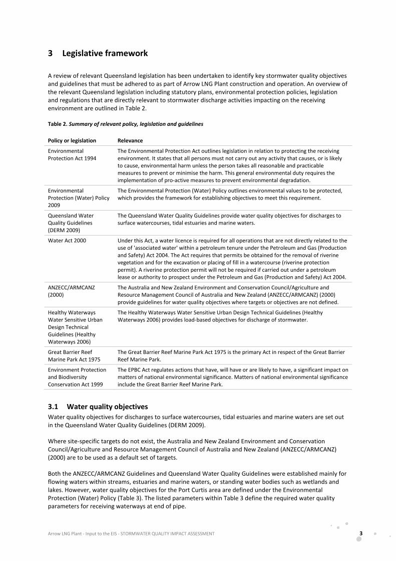
A review of relevant Queensland legislation has been undertaken to identify key stormwater quality objectives and guidelines that must be adhered to as part of Arrow LNG Plant construction and operation. An overview of the relevant Queensland legislation including statutory plans, environmental protection policies, legislation and regulations that are directly relevant to stormwater discharge activities impacting on the receiving environment are outlined in Table 2.
Table 2. Summary of relevant policy, legislation and guidelines
Policy or legislation Relevance
Environmental Protection Act 1994
The Environmental Protection Act outlines legislation in relation to protecting the receiving environment. It states that all persons must not carry out any activity that causes, or is likely to cause, environmental harm unless the person takes all reasonable and practicable measures to prevent or minimise the harm. This general environmental duty requires the implementation of pro-active measures to prevent environmental degradation.
Environmental Protection (Water) Policy 2009
The Environmental Protection (Water) Policy outlines environmental values to be protected, which provides the framework for establishing objectives to meet this requirement.
Queensland Water Quality Guidelines (DERM 2009)
The Queensland Water Quality Guidelines provide water quality objectives for discharges to surface watercourses, tidal estuaries and marine waters.
Water Act 2000 Under this Act, a water licence is required for all operations that are not directly related to the use of 'associated water' within a petroleum tenure under the Petroleum and Gas (Production and Safety) Act 2004. The Act requires that permits be obtained for the removal of riverine vegetation and for the excavation or placing of fill in a watercourse (riverine protection permit). A riverine protection permit will not be required if carried out under a petroleum lease or authority to prospect under the Petroleum and Gas (Production and Safety) Act 2004.
ANZECC/ARMCANZ (2000)
The Australia and New Zealand Environment and Conservation Council/Agriculture and Resource Management Council of Australia and New Zealand (ANZECC/ARMCANZ) (2000) provide guidelines for water quality objectives where targets or objectives are not defined.
Healthy Waterways Water Sensitive Urban Design Technical Guidelines (Healthy Waterways 2006)
The Healthy Waterways Water Sensitive Urban Design Technical Guidelines (Healthy Waterways 2006) provides load-based objectives for discharge of stormwater.
Great Barrier Reef Marine Park Act 1975
The Great Barrier Reef Marine Park Act 1975 is the primary Act in respect of the Great Barrier Reef Marine Park.
Environment Protection and Biodiversity Conservation Act 1999
The EPBC Act regulates actions that have, will have or are likely to have, a significant impact on matters of national environmental significance. Matters of national environmental significance include the Great Barrier Reef Marine Park.
3.1 Water quality objectives Water quality objectives for discharges to surface watercourses, tidal estuaries and marine waters are set out in the Queensland Water Quality Guidelines (DERM 2009).
Where site-specific targets do not exist, the Australia and New Zealand Environment and Conservation Council/Agriculture and Resource Management Council of Australia and New Zealand (ANZECC/ARMCANZ) (2000) are to be used as a default set of targets.
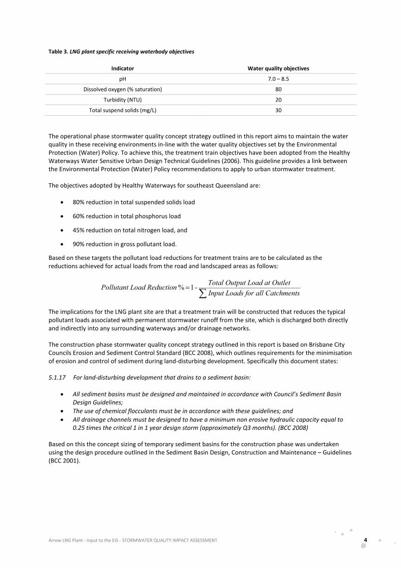
Both the ANZECC/ARMCANZ Guidelines and Queensland Water Quality Guidelines were established mainly for flowing waters within streams, estuaries and marine waters, or standing water bodies such as wetlands and lakes. However, water quality objectives for the Port Curtis area are defined under the Environmental Protection (Water) Policy (Table 3). The listed parameters within Table 3 define the required water quality parameters for receiving waterways at end of pipe.
Arrow LNG Plant - Input to the EIS - STORMWATER QUALITY IMPACT ASSESSMENT 4
Table 3. LNG plant specific receiving waterbody objectives
Indicator Water quality objectives
pH 7.0 – 8.5
Dissolved oxygen (% saturation) 80
Turbidity (NTU) 20
Total suspend solids (mg/L) 30
The operational phase stormwater quality concept strategy outlined in this report aims to maintain the water quality in these receiving environments in-line with the water quality objectives set by the Environmental Protection (Water) Policy. To achieve this, the treatment train objectives have been adopted from the Healthy Waterways Water Sensitive Urban Design Technical Guidelines (2006). This guideline provides a link between the Environmental Protection (Water) Policy recommendations to apply to urban stormwater treatment.
The objectives adopted by Healthy Waterways for southeast Queensland are:
• 80% reduction in total suspended solids load
• 60% reduction in total phosphorus load
• 45% reduction on total nitrogen load, and
• 90% reduction in gross pollutant load.
Based on these targets the pollutant load reductions for treatment trains are to be calculated as the reductions achieved for actual loads from the road and landscaped areas as follows:
∑=
Catchmentss for all Input Load Outletut Load atTotal OutptionLoad ReducPollutant - 1 %
The implications for the LNG plant site are that a treatment train will be constructed that reduces the typical pollutant loads associated with permanent stormwater runoff from the site, which is discharged both directly and indirectly into any surrounding waterways and/or drainage networks.
The construction phase stormwater quality concept strategy outlined in this report is based on Brisbane City Councils Erosion and Sediment Control Standard (BCC 2008), which outlines requirements for the minimisation of erosion and control of sediment during land-disturbing development. Specifically this document states:
5.1.17 For land-disturbing development that drains to a sediment basin:
• All sediment basins must be designed and maintained in accordance with Council’s Sediment Basin Design Guidelines;
• The use of chemical flocculants must be in accordance with these guidelines; and • All drainage channels must be designed to have a minimum non erosive hydraulic capacity equal to
0.25 times the critical 1 in 1 year design storm (approximately Q3 months). (BCC 2008)
Based on this the concept sizing of temporary sediment basins for the construction phase was undertaken using the design procedure outlined in the Sediment Basin Design, Construction and Maintenance – Guidelines (BCC 2001).
Arrow LNG Plant - Input to the EIS - STORMWATER QUALITY IMPACT ASSESSMENT 5
4 Conceptual stormwater quality treatment arrangement
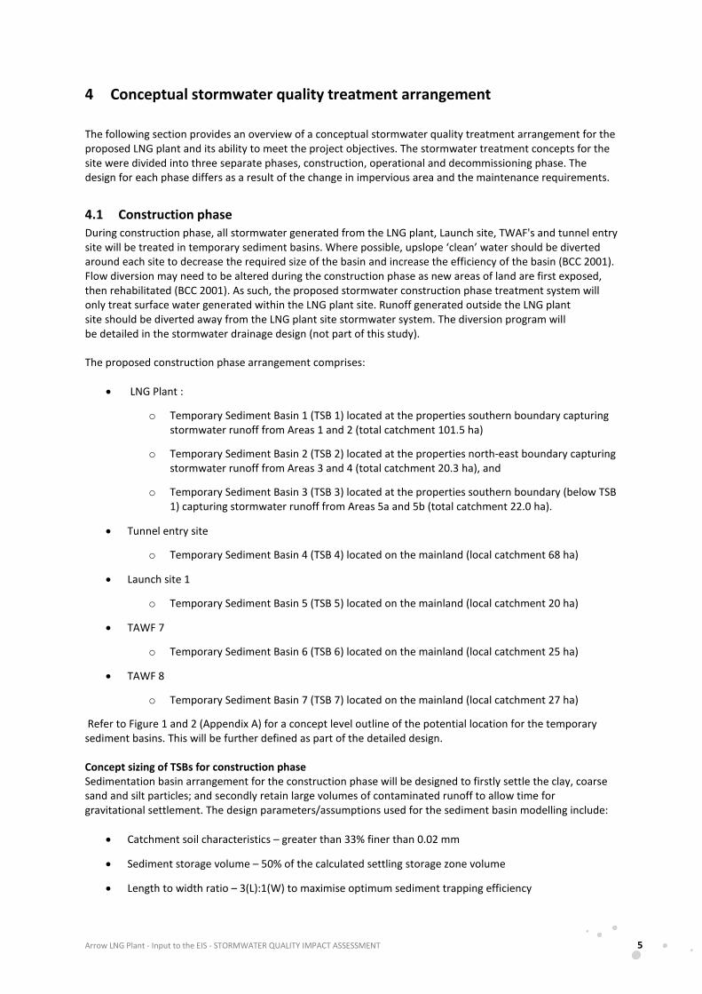
The following section provides an overview of a conceptual stormwater quality treatment arrangement for the proposed LNG plant and its ability to meet the project objectives. The stormwater treatment concepts for the site were divided into three separate phases, construction, operational and decommissioning phase. The design for each phase differs as a result of the change in impervious area and the maintenance requirements.
4.1 Construction phase During construction phase, all stormwater generated from the LNG plant, Launch site, TWAF's and tunnel entry site will be treated in temporary sediment basins. Where possible, upslope ‘clean’ water should be diverted around each site to decrease the required size of the basin and increase the efficiency of the basin (BCC 2001). Flow diversion may need to be altered during the construction phase as new areas of land are first exposed, then rehabilitated (BCC 2001). As such, the proposed stormwater construction phase treatment system will only treat surface water generated within the LNG plant site. Runoff generated outside the LNG plant site should be diverted away from the LNG plant site stormwater system. The diversion program will be detailed in the stormwater drainage design (not part of this study).
The proposed construction phase arrangement comprises:
• LNG Plant :
o Temporary Sediment Basin 1 (TSB 1) located at the properties southern boundary capturing stormwater runoff from Areas 1 and 2 (total catchment 101.5 ha)
o Temporary Sediment Basin 2 (TSB 2) located at the properties north-east boundary capturing stormwater runoff from Areas 3 and 4 (total catchment 20.3 ha), and
o Temporary Sediment Basin 3 (TSB 3) located at the properties southern boundary (below TSB 1) capturing stormwater runoff from Areas 5a and 5b (total catchment 22.0 ha).
• Tunnel entry site
o Temporary Sediment Basin 4 (TSB 4) located on the mainland (local catchment 68 ha)
• Launch site 1
o Temporary Sediment Basin 5 (TSB 5) located on the mainland (local catchment 20 ha)
• TAWF 7
o Temporary Sediment Basin 6 (TSB 6) located on the mainland (local catchment 25 ha)
• TAWF 8
o Temporary Sediment Basin 7 (TSB 7) located on the mainland (local catchment 27 ha)
Refer to Figure 1 and 2 (Appendix A) for a concept level outline of the potential location for the temporary sediment basins. This will be further defined as part of the detailed design.
Concept sizing of TSBs for construction phase Sedimentation basin arrangement for the construction phase will be designed to firstly settle the clay, coarse sand and silt particles; and secondly retain large volumes of contaminated runoff to allow time for gravitational settlement. The design parameters/assumptions used for the sediment basin modelling include:
• Catchment soil characteristics – greater than 33% finer than 0.02 mm
• Sediment storage volume – 50% of the calculated settling storage zone volume
• Length to width ratio – 3(L):1(W) to maximise optimum sediment trapping efficiency
Arrow LNG Plant - Input to the EIS - STORMWATER QUALITY IMPACT ASSESSMENT 6
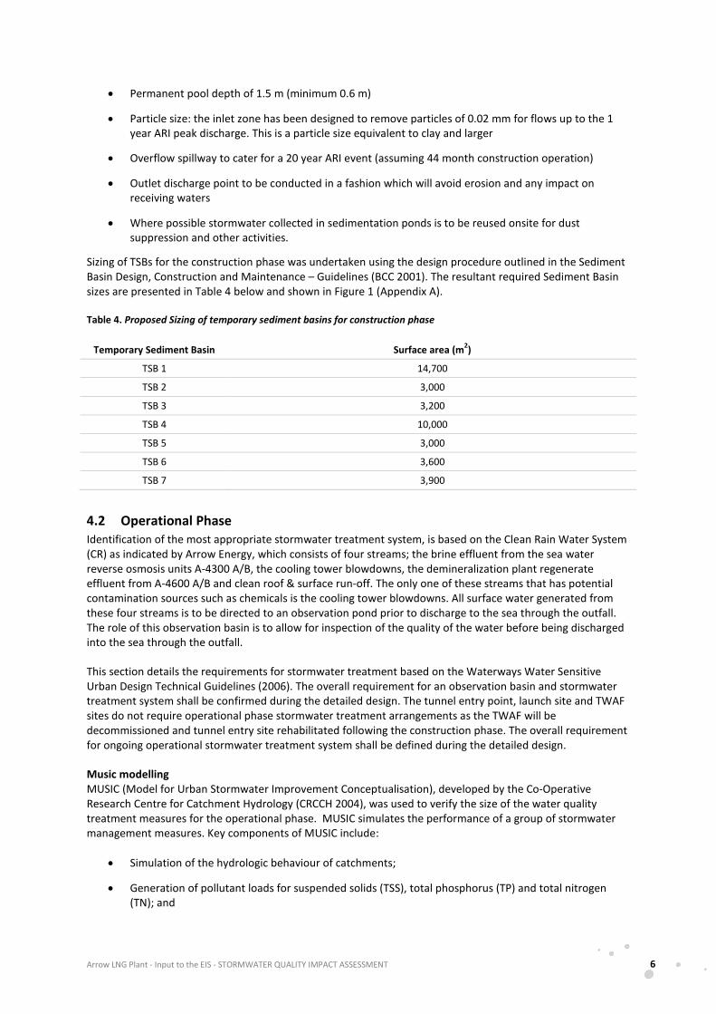
• Permanent pool depth of 1.5 m (minimum 0.6 m)
• Particle size: the inlet zone has been designed to remove particles of 0.02 mm for flows up to the 1 year ARI peak discharge. This is a particle size equivalent to clay and larger
• Overflow spillway to cater for a 20 year ARI event (assuming 44 month construction operation)
• Outlet discharge point to be conducted in a fashion which will avoid erosion and any impact on receiving waters
• Where possible stormwater collected in sedimentation ponds is to be reused onsite for dust suppression and other activities.
Sizing of TSBs for the construction phase was undertaken using the design procedure outlined in the Sediment Basin Design, Construction and Maintenance – Guidelines (BCC 2001). The resultant required Sediment Basin sizes are presented in Table 4 below and shown in Figure 1 (Appendix A).
Table 4. Proposed Sizing of temporary sediment basins for construction phase
Temporary Sediment Basin Surface area (m2)
TSB 1 14,700
TSB 2 3,000
TSB 3 3,200
TSB 4 10,000
TSB 5 3,000
TSB 6 3,600
TSB 7 3,900
4.2 Operational Phase Identification of the most appropriate stormwater treatment system, is based on the Clean Rain Water System (CR) as indicated by Arrow Energy, which consists of four streams; the brine effluent from the sea water reverse osmosis units A-4300 A/B, the cooling tower blowdowns, the demineralization plant regenerate effluent from A-4600 A/B and clean roof & surface run-off. The only one of these streams that has potential contamination sources such as chemicals is the cooling tower blowdowns. All surface water generated from these four streams is to be directed to an observation pond prior to discharge to the sea through the outfall. The role of this observation basin is to allow for inspection of the quality of the water before being discharged into the sea through the outfall.
This section details the requirements for stormwater treatment based on the Waterways Water Sensitive Urban Design Technical Guidelines (2006). The overall requirement for an observation basin and stormwater treatment system shall be confirmed during the detailed design. The tunnel entry point, launch site and TWAF sites do not require operational phase stormwater treatment arrangements as the TWAF will be decommissioned and tunnel entry site rehabilitated following the construction phase. The overall requirement for ongoing operational stormwater treatment system shall be defined during the detailed design.
Music modelling MUSIC (Model for Urban Stormwater Improvement Conceptualisation), developed by the Co-Operative Research Centre for Catchment Hydrology (CRCCH 2004), was used to verify the size of the water quality treatment measures for the operational phase. MUSIC simulates the performance of a group of stormwater management measures. Key components of MUSIC include:
• Simulation of the hydrologic behaviour of catchments;
• Generation of pollutant loads for suspended solids (TSS), total phosphorus (TP) and total nitrogen (TN); and
Arrow LNG Plant - Input to the EIS - STORMWATER QUALITY IMPACT ASSESSMENT 7
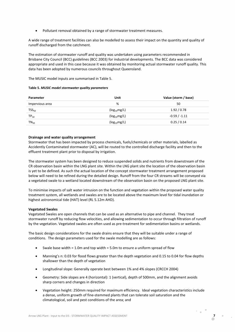
• Pollutant removal obtained by a range of stormwater treatment measures.
A wide range of treatment facilities can also be modelled to assess their impact on the quantity and quality of runoff discharged from the catchment.
The estimation of stormwater runoff and quality was undertaken using parameters recommended in Brisbane City Council (BCC) guidelines (BCC 2003) for industrial developments. The BCC data was considered appropriate and used in this case because it was obtained by monitoring actual stormwater runoff quality. This data has been adopted by numerous councils throughout Queensland.
The MUSIC model inputs are summarised in Table 5.
Table 5. MUSIC model stormwater quality parameters
Parameter Unit Value (storm / base)
Impervious area % 50
TSS50 (log10mg/L) 1.92 / 0.78
TP50 (log10mg/L) -0.59 / -1.11
TN50 (log10mg/L) 0.25 / 0.14
Drainage and water quality arrangement Stormwater that has been impacted by process chemicals, fuels/chemicals or other materials, labelled as Accidently Contaminated stormwater (AC), will be routed to the controlled discharge facility and then to the effluent treatment plant prior to disposal by irrigation.
The stormwater system has been designed to reduce suspended solids and nutrients from downstream of the CR observation basin within the LNG plant site. Within the LNG plant site the location of the observation basin is yet to be defined. As such the actual location of the concept stormwater treatment arrangement proposed below will need to be refined during the detailed design. Runoff from the four CR streams will be conveyed via a vegetated swale to a wetland located downstream of the observation basin on the proposed LNG plant site.
To minimise impacts of salt water intrusion on the function and vegetation within the proposed water quality treatment system, all wetlands and swales are to be located above the maximum level for tidal inundation or highest astronomical tide (HAT) level (RL 5.12m AHD).
Vegetated Swales Vegetated Swales are open channels that can be used as an alternative to pipe and channel. They treat stormwater runoff by reducing flow velocities, and allowing sedimentation to occur through filtration of runoff by the vegetation. Vegetated swales are often used as pre-treatment for sedimentation basins or wetlands.
The basic design considerations for the swale drains ensure that they will be suitable under a range of conditions. The design parameters used for the swale modelling are as follows:
• Swale base width = 1.0m and top width = 5.0m to ensure a uniform spread of flow
• Manning’s n: 0.03 for flood flows greater than the depth vegetation and 0.15 to 0.04 for flow depths shallower than the depth of vegetation
• Longitudinal slope: Generally operate best between 1% and 4% slopes (CRCCH 2004)
• Geometry: Side slopes are 4 (horizontal): 1 (vertical), depth of 500mm, and the alignment avoids sharp corners and changes in direction
• Vegetation height: 250mm required for maximum efficiency. Ideal vegetation characteristics include a dense, uniform growth of fine-stemmed plants that can tolerate soil saturation and the climatological, soil and pest conditions of the area; and
Arrow LNG Plant - Input to the EIS - STORMWATER QUALITY IMPACT ASSESSMENT 8
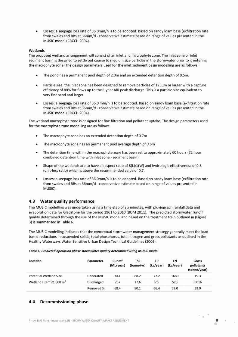
• Losses: a seepage loss rate of 36.0mm/h is to be adopted. Based on sandy loam base (exfiltration rate from swales and RBs at 36mm/d - conservative estimate based on range of values presented in the MUSIC model (CRCCH 2004).
Wetlands The proposed wetland arrangement will consist of an inlet and macrophyte zone. The inlet zone or inlet sediment basin is designed to settle out coarse to medium size particles in the stormwater prior to it entering the macrophyte zone. The design parameters used for the inlet sediment basin modelling are as follows:
• The pond has a permanent pool depth of 2.0m and an extended detention depth of 0.5m.
• Particle size: the inlet zone has been designed to remove particles of 125µm or larger with a capture efficiency of 80% for flows up to the 1 year ARI peak discharge. This is a particle size equivalent to very fine sand and larger.
• Losses: a seepage loss rate of 36.0 mm/h is to be adopted. Based on sandy loam base (exfiltration rate from swales and RBs at 36mm/d - conservative estimate based on range of values presented in the MUSIC model (CRCCH 2004).
The wetland macrophyte zone is designed for fine filtration and pollutant uptake. The design parameters used for the macrophyte zone modelling are as follows:
• The macrophyte zone has an extended detention depth of 0.7m
• The macrophyte zone has an permanent pool average depth of 0.6m
• The detention time within the macrophyte zone has been set to approximately 60 hours (72 hour combined detention time with inlet zone - sediment basin)
• Shape of the wetlands are to have an aspect ratio of 8(L):1(W) and hydrologic effectiveness of 0.8 (unit-less ratio) which is above the recommended value of 0.7.
• Losses: a seepage loss rate of 36.0mm/h is to be adopted. Based on sandy loam base (exfiltration rate from swales and RBs at 36mm/d - conservative estimate based on range of values presented in MUSIC).
4.3 Water quality performance The MUSIC modelling was undertaken using a time-step of six minutes, with pluviograph rainfall data and evaporation data for Gladstone for the period 1961 to 2010 (BOM 2011). The predicted stormwater runoff quality determined through the use of the MUSIC model and based on the treatment train outlined in (Figure 3) is summarised in Table 6.
The MUSIC modelling indicates that the conceptual stormwater management strategy generally meet the load based reductions in suspended solids, total phosphorus, total nitrogen and gross pollutants as outlined in the Healthy Waterways Water Sensitive Urban Design Technical Guidelines (2006).
Table 6. Predicted operation phase stormwater quality determined using MUSIC model
Location Parameter Runoff (ML/year)
TSS (tonne/yr)
TP (kg/year)
TN (kg/year)
Gross pollutants
(tonne/year)
Potential Wetland Size Generated 844 88.2 77.2 1680 19.3
Wetland size ~ 21,000 m2 Discharged 267 17.6 26 523 0.016
Removed % 68.4 80.1 66.4 69.0 99.9
4.4 Decommissioning phase

Arrow LNG Plant - Input to the EIS - STORMWATER QUALITY IMPACT ASSESSMENT 9
The proposed stormwater treatment system for the operational phase should be maintained and keep operational during the decommissioning phase. Operation of the conceptual stormwater treatment arrangement outlined in the operational phase should continue to operate until monitoring has shown no significant loads of sediment are leaving the rehabilitated site. As part of detailed design works, the design/optimisation of the stormwater quality treatment arrangement including size and location will be determined.
5 Maintenance
The proposed sediment basin and swale drains should be constructed during the initial bulk earthworks activities. All runoff from the site generated during the construction period should be directed to the sediment basin and the swale drains in order to minimise the sediment loads discharged from the site during construction. Maintenance of the stormwater treatment facilities is critical to ensure effective treatment of stormwater. Maintenance activities and schedules are recommended for the construction and establishment phase, and ongoing maintenance of the system.
5.1 Construction Phase Regular checks of the sediment basins will need to be undertaken during the construction for the following items:
• Inspection of the sediment basins:
o during construction: to determine whether machinery, falling trees, or construction activity has damaged any components of the sediment basin. If damage has occurred, repair it.
o after each runoff event: to ensure that runoff into the basin hasn’t caused damage or sediment has accumulated to a level where it must be removed. If damage has occurred, make the necessary repairs. If necessary, remove the accumulated sediment and restore the original storage volume.
• Clean out accumulated sediment when it reaches the top of design sediment storage volume. Place sediment in a disposal area or, if appropriate, mix with dry soil on the site. Do not dispose of sediment in a manner that will create an erosion hazard.
• Check all pipe connections for leaks, and repair as necessary.
• Check fill material in the embankment for excessive settlement, slumping of the slopes or piping between the conduit and the embankment; make all necessary repairs.
• Remove all trash and other debris from the basin and riser.
5.2 Operational and Decommission Phases
Establishment phase (first two years) Regular checks need to be undertaken during the construction and establishment phase (2 years from the commencement of operation) for the following items:
• Rills and erosion forming in swales.
• Undesired overgrowth vegetation from taking over the area, i.e. weeds within and around the treatment systems.
Arrow LNG Plant - Input to the EIS - STORMWATER QUALITY IMPACT ASSESSMENT 10
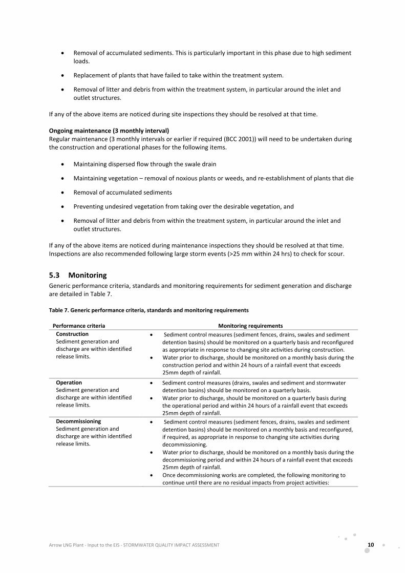
• Removal of accumulated sediments. This is particularly important in this phase due to high sediment loads.
• Replacement of plants that have failed to take within the treatment system.
• Removal of litter and debris from within the treatment system, in particular around the inlet and outlet structures.
If any of the above items are noticed during site inspections they should be resolved at that time.
Ongoing maintenance (3 monthly interval) Regular maintenance (3 monthly intervals or earlier if required (BCC 2001)) will need to be undertaken during the construction and operational phases for the following items.
• Maintaining dispersed flow through the swale drain
• Maintaining vegetation – removal of noxious plants or weeds, and re-establishment of plants that die
• Removal of accumulated sediments
• Preventing undesired vegetation from taking over the desirable vegetation, and
• Removal of litter and debris from within the treatment system, in particular around the inlet and outlet structures.
If any of the above items are noticed during maintenance inspections they should be resolved at that time. Inspections are also recommended following large storm events (>25 mm within 24 hrs) to check for scour.
5.3 Monitoring Generic performance criteria, standards and monitoring requirements for sediment generation and discharge are detailed in Table 7.
Table 7. Generic performance criteria, standards and monitoring requirements
Performance criteria Monitoring requirements Construction Sediment generation and discharge are within identified release limits.
• Sediment control measures (sediment fences, drains, swales and sediment detention basins) should be monitored on a quarterly basis and reconfigured as appropriate in response to changing site activities during construction.
• Water prior to discharge, should be monitored on a monthly basis during the construction period and within 24 hours of a rainfall event that exceeds 25mm depth of rainfall.
Operation Sediment generation and discharge are within identified release limits.
• Sediment control measures (drains, swales and sediment and stormwater detention basins) should be monitored on a quarterly basis.
• Water prior to discharge, should be monitored on a quarterly basis during the operational period and within 24 hours of a rainfall event that exceeds 25mm depth of rainfall.
Decommissioning Sediment generation and discharge are within identified release limits.
• Sediment control measures (sediment fences, drains, swales and sediment detention basins) should be monitored on a monthly basis and reconfigured, if required, as appropriate in response to changing site activities during decommissioning.
• Water prior to discharge, should be monitored on a monthly basis during the decommissioning period and within 24 hours of a rainfall event that exceeds 25mm depth of rainfall.
• Once decommissioning works are completed, the following monitoring to continue until there are no residual impacts from project activities:
Arrow LNG Plant - Input to the EIS - STORMWATER QUALITY IMPACT ASSESSMENT 11
6 Conclusion
This assessment has identified the likely impacts on stormwater quality from the construction and operation of the LNG facility and identified concept level options which can be implemented to prevent or minimise the identified impacts in line with regulatory requirements. Prior to commencement of any construction works the detail design of the stormwater quality treatment measures will need to be undertaken to ensure they fit within the final site arrangement.
Critical to successful operation of these stormwater quality treatment measures is the development of a detailed maintenance and monitoring plan to ensure drainage management measures and sediment control structures continue to operate at maximum efficiency and meet the regulatory requirements.
The concept stormwater systems presented in this report demonstrates that a workable solution can be located within the currently identified area of disturbance. The design and optimisation of the stormwater quality treatment arrangement including size and location will be further defined as part of detailed design works.
7 References
Alluvium, 2011. Arrow LNG Plant – Input to the Environmental Impact Statement: LNG Plant Surface Water Impact Assessment, Fluvial Geomorphology and Hydrology. Report RO1 by Alluvium for Arrow Energy Holdings Pty Ltd and Coffey Environments Pty Ltd, Brisbane.
Australia and New Zealand Environment and Conservation Council/Agriculture and Resource Management Council of Australia and New Zealand (ANZECC/ARMCANZ) 2000, National Water Quality Management Strategy: Australian and New Zealand Guidelines for fresh and marine water quality, Australian and New Zealand Environment and Conservation Council and the Agriculture and Resource Management Council of Australia and New Zealand, ISBN 09578245 0 5 (set).
Aquateco. 2011. Freshwater Ecology and Water Quality Impact Statement. Arrow LNG Plant. Environmental Impact Statement.
Brisbane City Council (BCC) 2001, Sediment Basin Design, Construction and Maintenance - Guidelines, Brisbane City Council, Brisbane.
Brisbane City Council (BCC) 2003, Guideline for Pollutant Export Modelling in Brisbane, Version 7, Brisbane City Council, Brisbane.
Brisbane City Council (BCC) 2008, Appendix 2 - Councils Erosion and Sediment Control Standard, Version 9, Brisbane City Council, Brisbane.
Bureau of Meteorology Pluviograph Online Service. Accessed March 2011. http://www.bom.gov.au
Cooperative Research Centre for Catchment Hydrology (2004). ‘MUSIC User Guide’.
Healthy Waterways 2006, Water Sensitive Urban Design Technical Design Guidelines for South East Queensland, Healthy Waterways, Queensland.
Melbourne Water (2005). ‘WSUD Engineering Procedures: Stormwater’.
Arrow LNG Plant - Input to the EIS - STORMWATER QUALITY IMPACT ASSESSMENT 12
Attachment A Stormwater Treatment System Arrangement
Arrow LNG Plant - Input to the EIS - STORMWATER QUALITY IMPACT ASSESSMENT 13
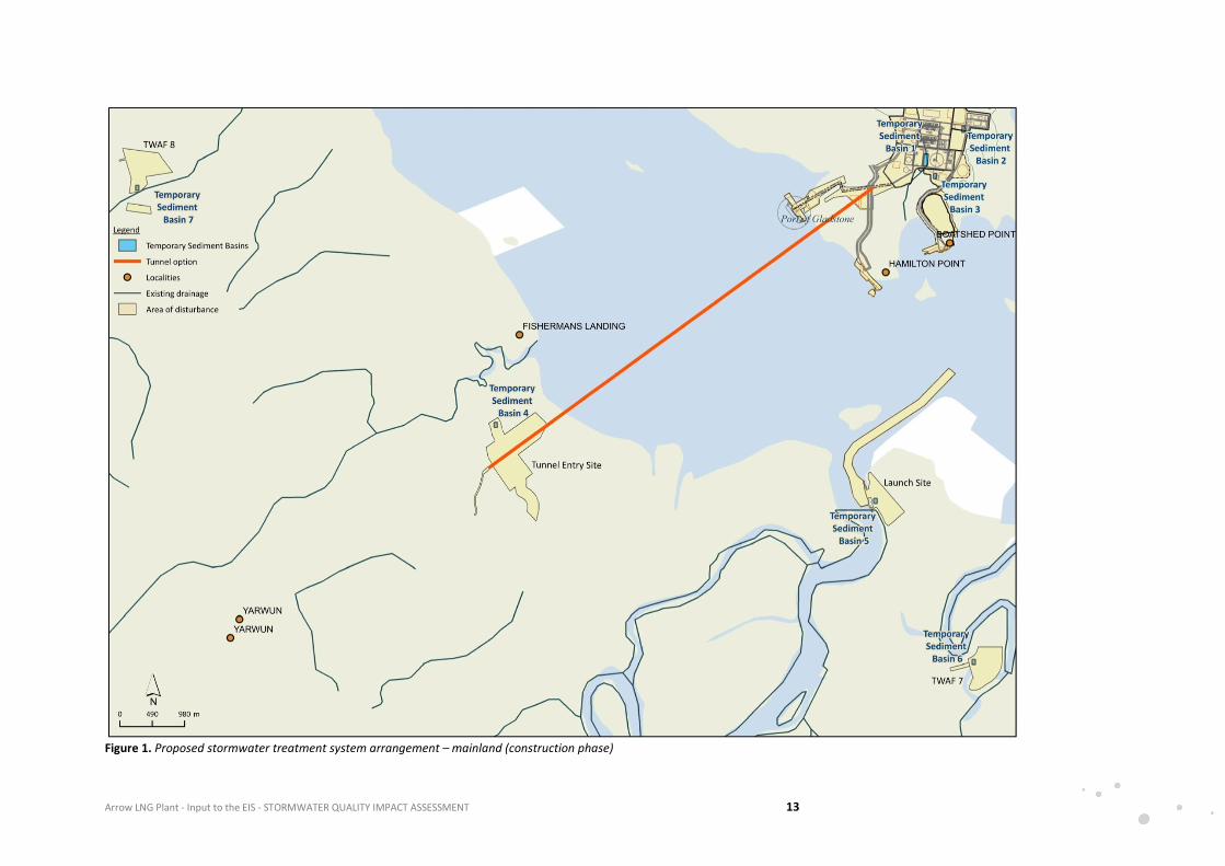
Figure 1. Proposed stormwater treatment system arrangement – mainland (construction phase)
Arrow LNG Plant - Input to the EIS - STORMWATER QUALITY IMPACT ASSESSMENT 14
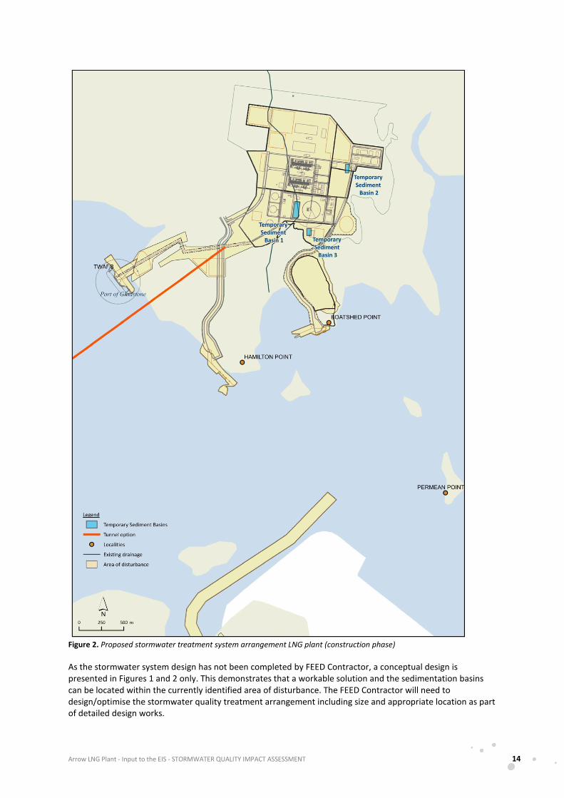
Figure 2. Proposed stormwater treatment system arrangement LNG plant (construction phase)
As the stormwater system design has not been completed by FEED Contractor, a conceptual design is presented in Figures 1 and 2 only. This demonstrates that a workable solution and the sedimentation basins can be located within the currently identified area of disturbance. The FEED Contractor will need to design/optimise the stormwater quality treatment arrangement including size and appropriate location as part of detailed design works.
Arrow LNG Plant - Input to the EIS - STORMWATER QUALITY IMPACT ASSESSMENT 15
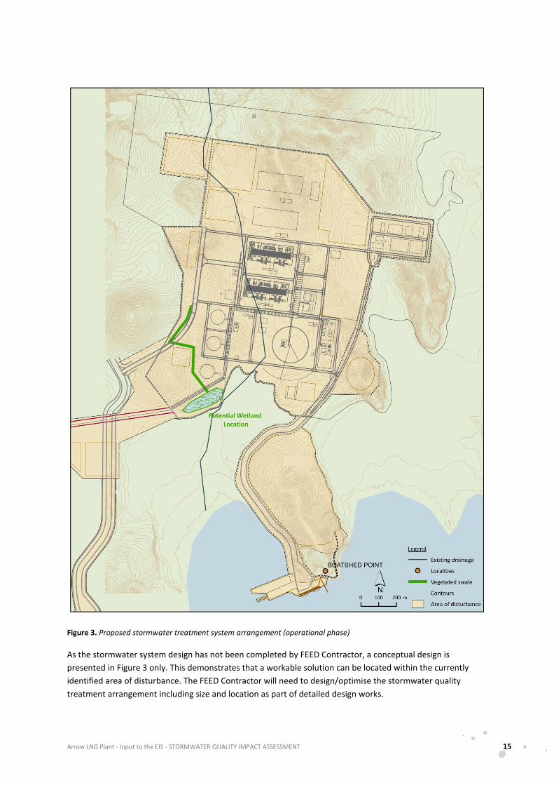
Figure 3. Proposed stormwater treatment system arrangement (operational phase)
As the stormwater system design has not been completed by FEED Contractor, a conceptual design is presented in Figure 3 only. This demonstrates that a workable solution can be located within the currently identified area of disturbance. The FEED Contractor will need to design/optimise the stormwater quality treatment arrangement including size and location as part of detailed design works.
Arrow LNG Plant - Input to the EIS - STORMWATER QUALITY IMPACT ASSESSMENT 16
Attachment B Arrow LNG Plant ToR Cross-reference Table

Arrow LNG Plant - Input to the EIS - STORMWATER QUALITY IMPACT ASSESSMENT 17
Table 8. Summary the ToR that are relevant to stormwater quality and cross-referenced to this report
ToR Section
Terms of Reference Requirement Technical Report Section No.
3.4
The definition of waters in the Environmental Protection (Water) Policy 1997 (EPP Water) includes the bed and banks of waters, so this section should address impacts on benthic sediments as well as the water column.
Where a licence or permit will be required under the Water Act 2000 to take or interfere with the flow of water, this section of the EIS should describe the amount of water to be taken and the details of the works to be constructed, and impacts of the works.
Section 3
3.4.1 Surface water and watercourses
Describe the environmental values of the surface waterways of the affected area in terms of:
• Values identified in the EPP (Water) and Australian and New Zealand Environment and Conservation Council, State of the Environment Reporting Taskforce 2000 (ANZECC 2000)
Section 2
• Sustainability, including both quality and quantity. Quantity – Alluvium (2011)
Quality issues addressed in Section 2.3 and Aquateco (2011)
• Physical integrity, fluvial processes and morphology of watercourses, including riparian zone vegetation and form.
Alluvium (2011)
See also Ecosure (2011)
• Any water resource plans, land and water management plans, declared or proposed wild river areas relevant to the affected catchment.
Alluvium (2011)
A description should be given of the surface watercourses and their quality and quantity in the area affected by the project with an outline of the significance of these waters to the river catchment system in which they occur. Details provided should include:
• A description of existing surface drainage patterns.
Alluvium (2011)
• A description of existing and historical flow regimes in major streams and wetlands. Alluvium (2011)
• A description of present and potential water uses downstream of the areas affected by the project. Alluvium (2011)
Details should be provided on the likelihood of flooding, history of flooding (including extent, levels and frequency). Flood studies should include:
• A range of annual exceedance probabilities for affected waterways, based on observed data if available, or use appropriate modelling techniques and conservative assumptions if there are no suitable observations.
The flood modelling should include:
• Local flooding due to short duration events from contributing catchments on site, as well as larger scale regional flooding including waterways downstream.
The EIS should provide a description, with photographic evidence where appropriate, of the geomorphic condition of any watercourses likely to be affected by project works and operations. The results of this description should form the basis for the planning and subsequent monitoring of rehabilitation of the affected watercourses.
An assessment is required of existing water quality in surface waters and wetlands likely to be affected by the proposal. The basis for this assessment should be a monitoring program, with sampling stations located upstream and downstream of the project areas. The water quality
Alluvium (2011)
Alluvium (2011)
Alluvium (2011) and Aquateco (2011)

Arrow LNG Plant - Input to the EIS - STORMWATER QUALITY IMPACT ASSESSMENT 18
ToR Section
Terms of Reference Requirement Technical Report Section No.
monitoring should capture seasonal variations or variations with flow where applicable. A relevant range of physical, chemical and biological parameters should be measured to provide a baseline for affected creek or wetland systems.
3.4.1.2
Potential impacts and mitigation measures
The water management systems for all project elements should be described, addressing surface water quality, quantity, drainage patterns and sediment movements.
The beneficial (environmental, production and recreational) use of nearby surface water should be discussed. An analysis of potential impacts on affected creeks should be carried out. This analysis should identify any likely inundation and duration, as this may affect emergency vehicle access
Monitoring programs should be described which will assess the effectiveness of management strategies for protecting water quality during the construction, operation and decommissioning of the project. Monitoring programs should also be designed to evaluate changes in the physical integrity and geomorphic processes associated with changed flow regimes in affected water courses.
Where on-site storage of water sourced from waste water treatment plants is proposed, the EIS should detail how this water would be managed to ensure environmental harm and human health risk is avoided. The EIS should also describe the design features of any such storages to effectively contain saline water and other harmful constituents.
Key water management strategy objectives include:
• Maintenance of sufficient quantity and quality of surface waters to protect existing beneficial downstream uses of those waters (including maintenance of in-stream biota).
• Maintenance or replication of the existing geomorphic conditions of local watercourses.
• Minimisation of impacts on flooding levels and frequencies both upstream and downstream of the project.
The EIS should include a risk assessment for uncontrolled emissions to water due to system or catastrophic failure, implications of such emissions for human health and natural ecosystems, and strategies to prevent, minimise and contain impacts.
The EIS should describe the proposed project component stormwater drainage systems and the proposed disposal arrangements, including any off-site services and downstream impacts.
Where dams, weirs, or ponds are proposed, the EIS should investigate the effects of predictable climatic extremes (droughts, floods) upon the structural integrity of the containing walls, and the quality of water contained, and flows and quality of water discharged.
A dam failure impact assessment should be carried out for any proposed dams that, due to their size, trigger the need for such an assessment under the Water Act 2000. Any dams that are likely to be referrable under the Water Act 2000 should be noted and emergency response procedures incorporated into the project's environmental management plan (EM Plan).
The need, or otherwise, for licensing of any dams (including referable dams) or creek diversions, under the Water Act 2000, or the Fisheries Act 1994, or the construction or raising of any waterway barrier works under the Fisheries Act 1994, should be discussed. The process for water allocation and water discharge should be established in consultation with DERM. Consideration should also be given to any water allocation and management plans.
The environmental values of the surface waters potentially affected by the project should be identified in accordance with the EPP (Water). Surface water quality objectives should be determined after consideration of the Australian and New Zealand Guidelines for Fresh and Marine Water Quality and the Queensland Water Quality Guidelines (DERM, 2009).
Risks from potentially contaminated surface water flow, particularly during flood events should be assessed.
Section 2 and 4
See also Alluvium (2011)
Alluvium (2011)
Section 5
Planager (2011)
Section 4 & Auateco (2011)
Section 4 & Alluvium (2011)
Alluvium (2011)
Alluvium (2011)
Planager (2011)
Section 4 & Alluvium (2011)
N/A
N/A
N/A
Aquateco (2011)
Aquateco (2011)
Alluvium (2011)

Arrow LNG Plant - Input to the EIS - STORMWATER QUALITY IMPACT ASSESSMENT 19
ToR Section
Terms of Reference Requirement Technical Report Section No.
Options for flood mitigation and the effectiveness of mitigation measures should be discussed with particular reference to sediment, salinity and other emissions of a hazardous or toxic nature to human health, flora or fauna.