Embed Size (px)
Citation preview


Risk Burn Guidance for July 2001Hazardous Waste Combustion Facilities
APPENDIX A
RISK BURN CONDITIONS AND PERMIT LIMITS FOR EXAMPLE FACILITIES
A.1 Risk Burn Conditions and Permit Limits for a Liquid Injection Incinerator (13 pages)
A.2 Risk Burn Conditions and Permit Limits for a Rotary Kiln Incinerator Burning
Containerized Wastes (16 pages)
Risk Burn Guidance for July 2001Hazardous Waste Combustion Facilities A.1-1
APPENDIX A.1
RISK BURN CONDITIONS AND PERMIT LIMITSFOR A LIQUID INJECTION INCINERATOR
Note: This illustrative example does not represent the only approach to structuring a trial burn/riskburn/MACT performance test. Other regulatory and permitting options exist. Test plans and final permitconditions should always be developed on a site-specific basis after close interaction between the regulatorand facility.
Appendix A.1 describes the risk burn and resulting permit limits for an example liquid injection incineration
facility (Facility Z). Facility Z burns organic liquid and aqueous wastes in a liquid injection combustion
chamber, followed by a heat recovery boiler and an air pollution control system consisting of a fabric filter
and venturi scrubber. Facility Z typically operates the combustion chamber within a 1,750 + 50 EF
temperature window, with exit gas temperatures from the heat recovery boiler in the range of 350 to 550 EF.
Gas exit temperatures from the heat recovery boiler generally increase and decrease with combustion
temperature. A review of historical operating data indicates that Facility Z consistently maintains steady-
state operations, with very low carbon monoxide and few waste feed cutoffs.
Facility Z needs to complete performance testing and a risk burn for a Resource Conservation and Recovery
Act (RCRA) permit renewal. In addition, Facility Z anticipates complying with the hazardous waste
combustor Maximum Achievable Control Technology (MACT) standards in the future, and has already
added an activated carbon injection system to control dioxins. By carefully structuring the test plan, Facility
Z can satisfy the current RCRA permitting needs, as well as generate data that may be submitted at a later
date as “data in lieu of the initial performance test” for MACT.
Facility Z begins writing the test plan with the following test conditions (summarized in Table A.1-1):
Destruction and Removal Efficiency Test Condition
A destruction and removal efficiency (DRE) demonstration will be conducted at a minimum combustion
temperature of 1,600 EF. This combustion temperature corresponds to a fabric filter inlet temperature of
Risk Burn Guidance for July 2001Hazardous Waste Combustion Facilities A.1-2
350EF. Other control parameters to be demonstrated during the DRE test include: 1) maximum combustion
gas velocity, as an indicator of minimum gas residence time; 2) maximum waste feed rate to each feed
location; and 3) worst-case operating conditions for air pollution control parameters (to the extent possible).
Continuous carbon monoxide and total hydrocarbon monitoring is also planned for this test. Operating
parameters to ensure good operation of the waste firing system will be based on manufacturer’s
specifications.
System Removal Efficiency Test Conditions
In anticipation of future MACT compliance, Facility Z adds test conditions to demonstrate system removal
efficiencies (SREs) for semivolatile and low-volatile metals (arsenic, beryllium, cadmium, chromium, and
lead). Stack determinations for particulate matter (PM) and hydrogen chloride (HCl) and chlorine (Cl2) are
also planned for the SRE tests.
The SRE demonstrations will be conducted at a maximum combustion temperature of 1,850 EF in order to
achieve a maximum inlet fabric filter temperature of 550 EF. Maximum semivolatile and low-volatile metal
feed rates will be achieved by spiking one metal from each of the two volatility groups. Since all of the feed
mechanisms at Facility Z are for liquid feeds, there is no distinction between total metal feed rates and
pumpable metal feed rates. Other control parameters to be demonstrated during the SRE test conditions
include: 1) maximum combustion gas velocity; 2) maximum chlorine feed rate; 3) maximum ash feed rate;
and 4) worst-case operating conditions for air pollution control parameters.
Two SRE test conditions are necessary to resolve conflicting parameters. Demonstration of the maximum
combustion gas velocity control parameter conflicts with demonstration of minimum pressure differential for
the venturi scrubber. The two SRE test conditions are designated as SRE 1 and SRE 2 in Table A.1-1.
During the SRE 1 test condition, maximum combustion gas velocity will be demonstrated. During the SRE 2
test condition, minimum pressure differential for the venturi scrubber will be demonstrated, and all other
control parameters will be maintained as close as possible to the SRE 1 conditions. Demonstration of the
maximum combustion gas velocity control parameter also conflicts with demonstration of minimum pressure
differential for the fabric filter. However, Facility Z observes that the MACT rule allows minimum and

Risk Burn Guidance for July 2001Hazardous Waste Combustion Facilities A.1-3
maximum fabric filter pressure differential to be established based on manufacturer’s specifications, and the
permit writer agrees with this approach.
For mercury, Facility Z wishes to avoid spiking and will not demonstrate a maximum mercury feed rate
during the SRE test. Facility Z plans to conservatively assume that 100% of the mercury fed to the unit is
emitted (even though some mercury control will be achieved from the carbon injection system).
Risk Burn Determinations and Addition of a Normal Test Condition
To complete a site-specific risk assessment, Facility Z recognizes that stack emissions determinations are
needed for: dioxins/furans (D/Fs); organics other than D/Fs; the eighteen toxic metals listed in Section 2.3;
particle-size distribution; and HCl/Cl2. Facility Z incorporates these determinations into the test plan as
follows:
D/Fs
The primary operating parameters related to D/F formation for Facility Z are boiler exit temperature
and fabric filter inlet temperature (both operating parameters are represented by the same
measurement location for the Facility Z system configuration), as well as control parameters for the
carbon injection system. D/Fs are expected to be maximized at the maximum fabric filter inlet
temperature of 550 EF, and will therefore be measured in conjunction with the SRE tests.
D/F testing will also be performed during the DRE test because of the permit writer’s concern that
the high combustion temperatures demonstrated during the SRE test might not adequately represent
D/F precursors which could be formed during lower temperature combustion situations. In general,
the formation of D/F precursors due to poor combustion should not be a significant concern for this
system (because of the historical data indicating steady-state operation). Also, the 350EF fabric filter
inlet temperature planned for the DRE test is outside of the critical D/F temperature range (400 - 750
EF). However, the facility agrees that D/F sampling during DRE conditions will better represent the
complete operating envelope, and will put Facility Z in a better position to potentially use the data for

Risk Burn Guidance for July 2001Hazardous Waste Combustion Facilities A.1-4
future MACT compliance (control parameters for minimum combustion temperatures, maximum
waste feed rates, and maximum gas flow rates are required to be demonstrated during D/F testing
pursuant to MACT). Therefore, Facility Z adds a D/F determination to the DRE test.
Non-D/F Organics
The feed and operating conditions that influence organic products of incomplete combustion (PICs)
are already represented during the DRE test. Therefore, the facility plans to measure PICs and total
organics in conjunction with the DRE performance demonstration. In addition, Facility Z arranges
for the sampling contractor to operate a temporary total hydrocarbon continuous emissions monitor
during the DRE/PIC testing.
Metals
The SRE tests already involve stack determinations for the five toxic metals identified in the MACT
rule. However, Facility Z is concerned that the metals spiking during the SRE tests may result in
emissions that exceed risk target values. Therefore, Facility Z proposes a separate test condition for
the purpose of generating metals emissions data for the risk assessment. A normal test is proposed
(as summarized in Table A.1-1) since Facility Z is capable of defining and maintaining normal
operating conditions for metals.
The normal test for metals will be conducted at normal metal feed rates, at a combustion temperature
of approximately 1,750 EF and a fabric filter inlet temperature of 450 EF. Emissions testing will be
performed for eighteen metals.
Particle-Size Distribution
For Facility Z, the fabric filter will be the primary determinant of particle-size distribution.
Therefore, significant variation in particle-size distribution between the different test conditions is not
expected. A particle-size determination is added to the normal test, since this test does not include

Risk Burn Guidance for July 2001Hazardous Waste Combustion Facilities A.1-5
ash spiking.
HCl and Cl2
Determinations for HCl and Cl2 are already included in the SRE tests, and this data can also be used
for the risk assessment.

Risk Burn Guidance for July 2001Hazardous Waste Combustion Facilities A.1-6
TABLE A.1-1
FACILITY Z TEST CONDITIONS
TEST CONDITIONS AND EMISSIONS DETERMINATIONS
DRE SRE 1 SRE 2 NORMAL
POHCs, PICs, D/Fs, TOE,Total Hydrocarbons, CarbonMonoxide
Metals, D/Fs, PM,HCl/Cl2, CarbonMonoxide
Metals, ParticleSize
Combustion temperature 1,600 EF 1,850 EF 1,750 EF
Fabric filter inlettemperature
350 EF 550 EF 450 EF
Organic liquid feed rate Maximum Maximum Normal
Aqueous liquid feed rate Maximum Minimum Normal
Combustion gas velocity Maximum * Maximum * Normal
Ash feed rate Above average Maximum Normal
Chlorine feed rate Maximum Maximum Normal
Spiked metal feed rates N/A Maximum Normal
Other metal feed rates N/A Normal Normal
Fabric filter differentialpressure
Within manufacturer’s specifications
Within manufacturer’s specifications
Normal
Venturi differentialpressure
Minimum *(or as close as possible)
Minimum * Normal
Venturi liquid-to-gas ratio Minimum Minimum Normal
Venturi scrubber liquidexit pH
Minimum Minimum Normal
Scrubber blowdown rate Minimum Minimum Normal
Carbon feed rate Minimum Minimum Normal
Notes:
* = conflicting parameters
D/Fs = Dioxins/furans PM = Particulate matterDRE = Destruction and removal efficiency POHCs = Principal organic hazardous constituentsN/A = Not applicable SRE = System removal efficiencyPICs = Products of incomplete combustion TOE = Total organic emissions

Risk Burn Guidance for July 2001Hazardous Waste Combustion Facilities A.1-7
Site-Specific Risk Assessment
Facility Z performs the tests according to the approved test plan. As expected, D/F emissions are highest
during the SRE test conditions. Emissions data are consolidated from all of the test conditions for evaluation
in a single multi-pathway human health and ecological site-specific risk assessment as follows:
C D/F emissions from the SRE test conditions are evaluated, together with . . .
C Organic PIC emissions from the DRE test condition, and . . .
C Metals emissions (18 metals) from the normal test condition, and . . .
C HCl and Cl2 emissions from the SRE test conditions.
Total chronic risks from these consolidated emissions are determined to be below target levels.
An acute risk evaluation is also performed to assess inhalation risks associated with maximum potential one-
hour emissions. Maximum one-hour emissions for the acute evaluation are estimated for D/Fs , other
organics, and HCl/Cl2 based on the test data listed above, with an upward adjustment to reflect upsets.
However, for metals, the test data are not representative of maximum potential one-hour emissions. For the
metals represented by the spiked metals (arsenic, beryllium, cadmium, chromium, and lead), the facility uses
an approved extrapolation procedure to estimate maximum one-hour emission rates based on maximum
anticipated one-hour feed rates and the SREs demonstrated during the testing. The extrapolated emissions
estimates are then adjusted further to reflect upsets. For the remaining metals, the facility estimates
maximum emissions based on maximum anticipated one-hour feed rates and an assumption of zero SRE.
Further upward adjustment for these metals is not necessary, since the “zero SRE” assumption already
represents the most conservative estimate. Acute risks associated with these maximum emissions estimates
are determined to be below target levels.
Finally, Facility Z performs a “post-MACT scenario” chronic risk evaluation. This evaluation is based on
emissions estimates for D/Fs, mercury, semivolatile metals, low-volatile metals, and HCl/Cl2, where the
emissions are determined assuming that Facility Z emits at the allowable MACT standard for these
Risk Burn Guidance for July 2001Hazardous Waste Combustion Facilities A.1-8
pollutants. These emission estimates are combined with the organic PIC emissions measured during the DRE
test, as well as the metals emissions for the non-MACT metals measured during the normal test. Total
chronic risks from these consolidated emissions are determined to be below target levels, with the exception
of mercury.
Final Permitted Emission Rates
As summarized in Table A.1-2, maximum emission rate limits are established in the RCRA permit for D/Fs,
metals, and HCl/Cl2 based on the levels needed to achieve target risk levels. The limits are established for the
purpose of periodic verification testing to ensure that emissions remain below those evaluated in the risk
assessment. If emissions increases occur above the permitted levels, then the permit calls for the risk
assessment to be repeated. Since none of the non-D/F organics were found to be risk drivers, emission limits
for individual non-D/F organic compounds are not established in the permit.
The “post-MACT scenario” risk evaluation showed that the MACT standards for D/Fs, arsenic, beryllium,
cadmium, chromium, lead, and HCl/Cl2 will be sufficiently protective. Therefore, the RCRA permit includes
“sunset” provisions on the emission limits for these pollutants in the RCRA permit. In this instance, the
sunset provisions are structured so that the RCRA emission limits will no longer apply once the facility has
documented compliance with MACT, and once the regulatory agency has completed a finding of compliance.
For mercury, the MACT standard will not be sufficiently protective if one assumes that the source
continuously emits at the standard. Therefore, the risk-based emission limits for mercury will remain in the
RCRA permit. Emission limits for the non-MACT metals (aluminum, antimony, barium, cobalt, copper,
manganese, nickel, selenium, silver, thallium, vanadium, and zinc) will also remain in the RCRA permit.
Final Permit Limits for Control Parameters
Table A.1-2 provides the final permit limits on relevant control parameters for Facility Z. Total hydrocarbon
levels were negligible during the DRE test condition. Therefore, the permit writer determines that there is no
need to specify continued total hydrocarbon monitoring as a condition of the RCRA permit.
For arsenic, beryllium, cadmium, chromium, lead, mercury, and nickel, acceptable risks were projected for at

Risk Burn Guidance for July 2001Hazardous Waste Combustion Facilities A.1-9
least one of the risk scenarios evaluated. However, since the projected risks came close to approaching target
risk levels, the permit writer determines that closer monitoring and control for these metals is warranted.
Therefore, quarterly average metals feed rate limits are established in the RCRA permit to ensure that these
metals are not fed at higher rates than those demonstrated. With the exception of mercury, the metals feed
rate limits are established in the RCRA permit based on feed rates demonstrated during the testing. For
mercury, a risk-based feed rate limit is conservatively calculated from the risk-based emissions limit by
assuming zero SRE (i.e., 100% of the mercury fed to the unit is emitted).
For the non-mercury metals, quarterly average feed rate limits are established based on two different test
scenarios. For arsenic, beryllium, cadmium, chromium and lead, the quarterly average feed rate limits are
established based on the SRE test (since the higher feed rates demonstrated during the SRE test were
demonstrated to achieve compliance with the MACT standards, and since the MACT standards were shown
to be sufficiently protective in the risk assessment). The RCRA permit is written with sunset provisions for
the feed rate limits on these five metals. For nickel, quarterly average feed rate limits are established based
on the normal test. The risk-based feed rate limits for nickel will remain in the RCRA permit after MACT.
Since risks from the remaining eleven metals were very far from target levels, and since target risk levels
could not possibly be exceeded based on the wastes burned at Facility Z, the permit writer decides to simply
document the risk assessment feed and emissions assumptions for the remaining metals in the administrative
record instead of imposing specific feed rate limits in the permit.
Short-term metal feed rate limits are not necessary for the RCRA permit, because acute risks were
determined to be negligible (considering the range of inputs for metals at Facility Z). Although the SRE tests
were performed for the purpose of establishing short-term metal feed rate limits for arsenic, beryllium,
cadmium, chromium, and lead, these limits will apply in the future pursuant to MACT and are not a RCRA
concern.
The RCRA permit is written with sunset provisions for all control parameters except for the quarterly
average feed rate limits for mercury and nickel.

Risk Burn Guidance for July 2001Hazardous Waste Combustion Facilities A.1-10
TABLE A.1-2
FINAL RCRA PERMIT LIMITS FOR FACILITY Z
Parameter Value
Basis
SunsetTest Established As:
Summary of Performance Standards and Emission Limits
DRE 99.99% for POHCs N/A Regulatory Limit Yes
Maximum PM Emissions 0.08 gr/dscf N/A Regulatory Limit Yes
HCl Larger of 99%removal or 4 lbs/hr
N/A Regulatory Limit Yes
Maximum HCl and Cl2emissions
Inhalation risk-based limits
N/A Target levels from riskassessment
Yes
Maximum D/F emissions Multi-pathwayrisk-based limit
N/A Target level from riskassessment
Yes
Maximum emissions(arsenic, beryllium,cadmium, chromium,lead)
Multi-pathwayrisk-based limits
N/A Target levels from riskassessment
Yes
Maximum emissions(aluminum, antimony,barium, cobalt, copper,manganese, mercury,nickel, selenium, silver,thallium, vanadium, zinc)
Multi-pathwayrisk-based limits
N/A Target levels from riskassessment
No
Group A Control Parameters - Interlocked with AWFCO
Minimum combustiontemperature
1,600 EF, HRA DRE Avg. of the test runaverages
Yes
Maximum combustiongas velocity
cfm, HRA SRE 1/DRE
Avg. of the test runaverages 1
Yes
Maximum organic liquidfeed rate
lbs/hr, HRA DRE Avg. of the test runaverages 1
Yes
Maximum aqueous feedrate
lbs/hr, HRA DRE Avg. of the test runaverages 1
Yes
Maximum fabric filterinlet temperature
550 EF, HRA SRE Avg. of the test runaverages
Yes

TABLE A.1-2
FINAL RCRA PERMIT LIMITS FOR FACILITY Z (continued)
Parameter Value
Basis
SunsetTest Established As:
Risk Burn Guidance for July 2001Hazardous Waste Combustion Facilities A.1-11
Minimum and maximumfabric filter pressuredifferential
inches watercolumn, HRA
N/A Manufacturer’sspecifications
Yes
Minimum venturiscrubber differentialpressure
inches watercolumn, HRA
SRE 2 Avg. of the test runaverages
Yes
Minimum venturi liquid-to-gas ratio
gal/cfm, HRA SRE Avg. of the test runaverages
Yes
Minimum venturiscrubber liquid exit pH
pH, HRA SRE Avg. of the test runaverages
Yes
Minimum carboninjection feed rate
lbs/hr, HRA DRE/SRE
Avg. of the test runaverages
Yes
Maximum stack carbonmonoxide concentration
100 ppm at 7%oxygen, dry basis,HRA
N/A Limit based on establishedguidance
Yes
Maximum combustionchamber pressure
inches watercolumn, vacuum,instantaneous limit
N/A As necessary to maintainnegative pressure
Yes
Group B Control Parameters
Restrictions on “moredifficult-to-burn POHCs”
AllowableAppendix VIIIconstituents
DRE More difficult-to-burnconstituents than thosewhich achieved 99.99%DRE are prohibited
Yes
Maximum chlorine feedrate
lbs/hr, HRA 2 SRE Avg. of the test runaverages
Yes
Maximum ash feed rate lbs/hr, HRA 3 SRE Avg. of the test runaverages 3
Yes
Maximum feed rates(arsenic, beryllium,cadmium, chromium, andlead)
lbs/hr, quarterlyaverage 2
SRE Avg. of the test runaverages
Yes
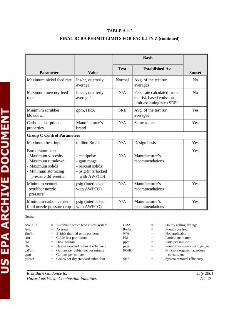
TABLE A.1-2
FINAL RCRA PERMIT LIMITS FOR FACILITY Z (continued)
Parameter Value
Basis
SunsetTest Established As:
Risk Burn Guidance for July 2001Hazardous Waste Combustion Facilities A.1-12
Maximum nickel feed rate lbs/hr, quarterlyaverage
Normal Avg. of the test runaverages
No
Maximum mercury feedrate
lbs/hr, quarterlyaverage 4
N/A Feed rate calculated fromthe risk-based emissionlimit assuming zero SRE 4
No
Minimum scrubberblowdown
gpm, HRA SRE Avg. of the test runaverages
Yes
Carbon adsorptionproperties
Manufacturer’sbrand
N/A Same as test Yes
Group C Control Parameters
Maximum heat input million Btu/hr N/A Design basis Yes
Burner/atomizer:- Maximum viscosity- Maximum turndown- Maximum solids- Minimum atomizing pressure differential
- centipoise- gpm range- percent solids- psig (interlocked with AWFCO)
N/A Manufacturer’srecommendations
Yes
Minimum venturi scrubber nozzle pressure
psig (interlockedwith AWFCO)
N/A Manufacturer’srecommendations
Yes
Minimum carbon carrierfluid nozzle pressure drop
psig (interlockedwith AWFCO)
N/A Manufacturer’srecommendations
Yes
Notes:
AWFCO = Automatic waste feed cutoff system HRA = Hourly rolling averageAvg. = Average lbs/hr = Pounds per hourBtu/hr = British thermal units per hour N/A = Not applicablecfm = Cubic feet per minute PM = Particulate matterD/F = Dioxin/furan ppm = Parts per millionDRE = Destruction and removal efficiency psig = Pounds per square inch, gaugegal/cfm = Gallons per cubic feet per minute POHC = Principle organic hazardousgpm = Gallons per minute constituentgr/dscf = Grains per dry standard cubic foot SRE = System removal efficiency
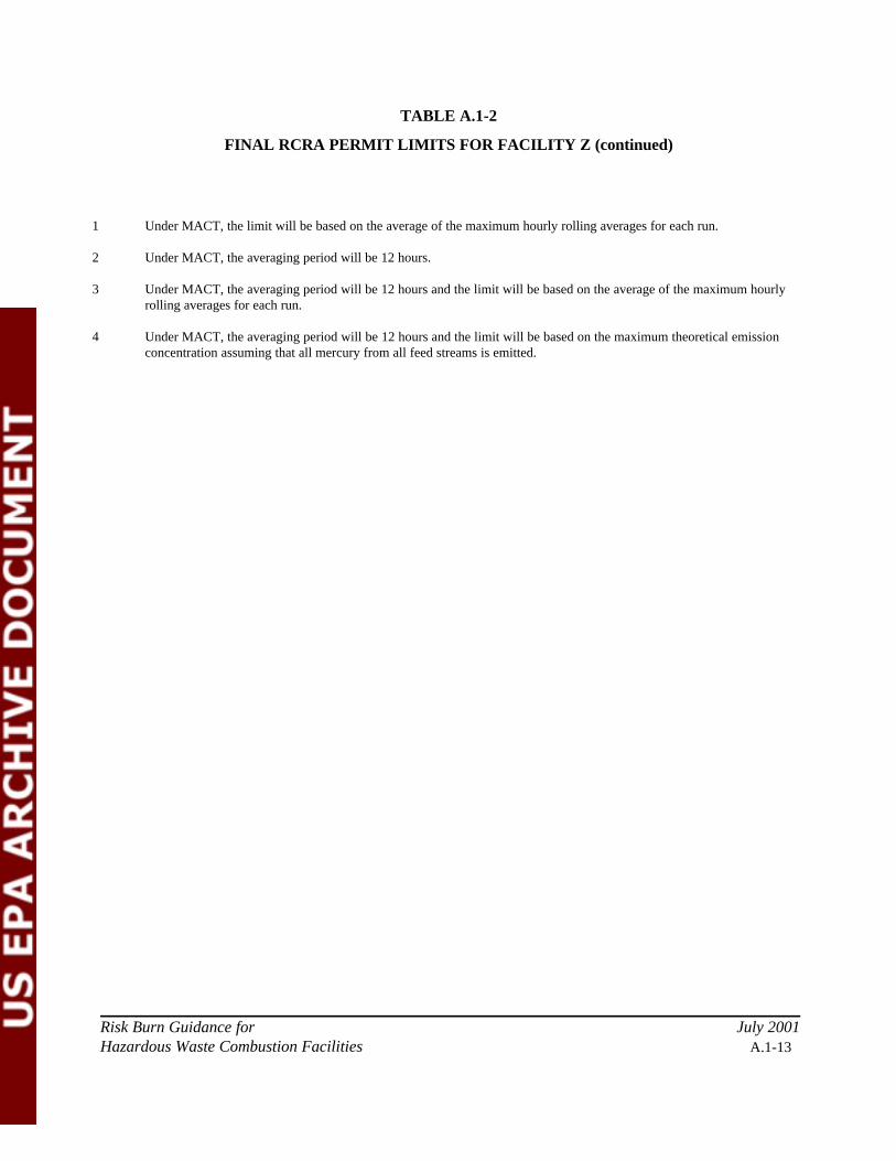
TABLE A.1-2
FINAL RCRA PERMIT LIMITS FOR FACILITY Z (continued)
Risk Burn Guidance for July 2001Hazardous Waste Combustion Facilities A.1-13
1 Under MACT, the limit will be based on the average of the maximum hourly rolling averages for each run.
2 Under MACT, the averaging period will be 12 hours.
3 Under MACT, the averaging period will be 12 hours and the limit will be based on the average of the maximum hourlyrolling averages for each run.
4 Under MACT, the averaging period will be 12 hours and the limit will be based on the maximum theoretical emissionconcentration assuming that all mercury from all feed streams is emitted.

Risk Burn Guidance for July 2001Hazardous Waste Combustion Facilities A.2-1
APPENDIX A.2
RISK BURN CONDITIONS AND PERMIT LIMITSFOR A ROTARY KILN INCINERATOR BURNING CONTAINERIZED WASTES
Note: This illustrative example does not represent the only approach to structuring a trial burn/riskburn/MACT performance test. Other regulatory and permitting options exist. Test plans and final permitconditions should always be developed on a site-specific basis after close interaction between the regulatorand facility.
Appendix A.2 describes the risk burn and resulting permit limits for an example rotary kiln incineration
facility (Facility Y). Facility Y burns a variety of waste streams including organic liquids, aqueous wastes,
organic sludges, bulk solids, and containerized wastes in a rotary kiln combustion chamber. The rotary kiln
is followed by a secondary combustion chamber, where organic liquids and aqueous wastes are fired. The
downstream air pollution control system consists of a spray dryer and fabric filter. Facility Y is a
commercial facility, and the waste streams received at the facility can be highly variable. A review of
historical operating data indicates that Facility Y routinely experiences transient operations, with carbon
monoxide spikes that often correlate with charges of containerized wastes to the unit.
Facility Y needs to complete performance testing and a risk burn for a Resource Conservation and Recovery
Act (RCRA) permit renewal. In addition, Facility Y anticipates complying with the hazardous waste
combustor Maximum Achievable Control Technology (MACT) standards in the future. By carefully
structuring the test plan, Facility Y can satisfy the current RCRA permitting needs, as well as generate data
that may be submitted at a later date as “data in lieu of the initial performance test” for MACT (this facility
does not need to physically modify the combustion system to comply with MACT).
Facility Y begins writing the test plan with the following test conditions (summarized in Table A.2-1):
Destruction and Removal Efficiency Test Conditions
Destruction and removal efficiency (DRE) demonstrations will be conducted at minimum primary
combustion chamber (PCC) and secondary combustion chamber (SCC) combustion temperatures of
Risk Burn Guidance for July 2001Hazardous Waste Combustion Facilities A.2-2
1,400 EF and 1,800 EF, respectively. Other control parameters to be demonstrated during the DRE tests
include: 1) maximum combustion gas velocity, as an indicator of minimum gas residence time; 2) maximum
waste feed rate to each feed location; and 3) worst-case operating conditions for air pollution control
parameters (to the extent possible). Continuous carbon monoxide and total hydrocarbon monitoring is also
planned for the DRE tests. Operating parameters to ensure good operation of the waste firing system will be
based on manufacturer’s specifications.
For the DRE determination, it is not possible to demonstrate maximum waste feed rates for all feed streams
simultaneously. Therefore, four (4) DRE test conditions are necessary. The four DRE test conditions are
designated as DRE 1, DRE 2, DRE 3, and DRE 4 in Table A.2-1. During each of the test conditions,
maximum feed rates for different individual waste streams will be demonstrated, while maintaining a
relatively constant maximum total thermal input to the PCC and total system (the unit is designed for 40
million (MM) Btu/hr thermal input to the PCC and 80 MM Btu/hr for the total system). Minimum
combustion temperatures and maximum combustion gas velocity will also be maintained throughout the four
test conditions. The maximum individual waste feed rate to be demonstrated during each condition follows:
C DRE 1 - Maximum organic liquid feed rate to the PCC - Maximum bulk solids feed rate to the PCC - Maximum container feed rate (mass basis) to the PCC - Maximum organic liquid feed rate to the SCC
C DRE 2 - Maximum container feed rate (thermal input basis) to the PCC
C DRE 3 - Maximum aqueous feed rate to the PCC - Maximum organic sludge feed rate to the PCC
C DRE 4 - Maximum aqueous feed rate to the SCC
The demonstration for containerized feeds encompasses two test conditions (DRE 1 and DRE 2). The
containerized wastes at Facility Y are fed in 55-gallon drums weighing 100 to 200 pounds each, and can be
highly variable. Containerized feeds can range from soil remediation waste (with high moisture and no
heating content) to high-heating-value, highly volatile organics sorbed onto a solid matrix.
In the DRE 1 test condition, Facility Y will demonstrate maximum containerized feed rate, as well as
Risk Burn Guidance for July 2001Hazardous Waste Combustion Facilities A.2-3
maximum total solids feed rate (for both the containerized and bulk feeds combined). Both feeds will consist
of contaminated, moist soils with no heating value (this type of material is representative of the bulk solids
which are normally burned, and is representative of materials which are sometimes burned in containers).
These conditions represent a challenging DRE test because of the heavy loading of solid material forming a
heat sink in the rotary kiln. The maximum containerized feed rate for the DRE 1 condition will be 9,000
lbs/hr, and the maximum container size will be 200 lb/hr, resulting in a feeding frequency of 45 drums per
hour.
A separate test condition, DRE 2, is necessary to represent containerized feeds consisting of high-heating-
value, highly volatile organics. For DRE 2, drums with a total heat content of 2 MM Btu each will be
prepared by adding a glass jar of highly volatile, high-heating-value liquid organics to a wood chip/plastic
pellet mixture. The drums will weigh 125 pounds each, and will be fed at the maximum rate allowed by the
thermal design capacity of the kiln (40 MM Btu/hr). This results in a feeding frequency of 20 drums per
hour. The DRE 2 test will be performed at a higher PCC temperature than the other DRE tests, because the
higher kiln temperature ensures a maximum volatilization rate. The higher PCC temperature, in combination
with the minimum SCC temperature, still represents a worst-case condition for organic destruction for
containerized feeds. In addition, combustion gas velocity for the DRE 2 condition will be slightly lower than
the other DRE conditions, since excess air to the PCC will be minimized in an attempt to minimize excess
oxygen at the location where the containers are fed.
Several batch/containerized feed parameters will not be demonstrated during the testing. Maximum batch
size (200 pounds) will be demonstrated during the DRE 1 condition, and maximum batch charge heat content
(which is the more important indicator of a situation that could overwhelm the combustion system) will be
demonstrated in the DRE 2 condition. However, maximum container feeding frequency will not be
demonstrated in either test, because Facility Y cannot simultaneously demonstrate maximum size (or
maximum batch charge heat content) and maximum feeding frequency. Larger batches fed less frequently
are considered to be worse than smaller batches fed more frequently, within the total targeted feed rate limits
for the containerized feeds of 9,000 lbs/hr and 40 MM Btu/hr for the DRE 1 and DRE 2 tests, respectively.
In addition, demonstration of maximum kiln rotation speed is not necessary, since the method of introducing
volatile liquids in glass jars will ensure a maximum rate of volatilization and puff intensity.

Risk Burn Guidance for July 2001Hazardous Waste Combustion Facilities A.2-4
During the DRE 1 and DRE 4 test conditions, maximum total ash feed rate and maximum atomized ash feed
rate will be demonstrated. Therefore, stack sampling for particulate matter will be performed during these
test conditions.
System Removal Efficiency Test Condition
In anticipation of future MACT compliance, Facility Y adds a test condition to demonstrate system removal
efficiencies (SREs) for semivolatile and low-volatile metals (arsenic, beryllium, cadmium, chromium, and
lead). Stack determinations for hydrogen chloride (HCl) and chlorine (Cl2) are also planned for the SRE test,
since chlorine will be maximized during this test and worst-case operating conditions for the spray dryer will
be demonstrated.
Maximum semivolatile and low-volatile metal feed rates will be achieved by spiking one metal from each of
the two volatility groups to the SCC organic liquid feed. Facility Y will base their total metal feed rate limits
only on metals in the SCC feed stream, so that separate feed rate limits on total and pumpable feed streams
will not be needed (metals fed as liquids to the SCC constitute a worst-case test).
The SRE demonstration will be conducted at a maximum SCC combustion temperature of 2,200 EF to
achieve a maximum inlet fabric filter inlet temperature of 400 EF. Other control parameters to be
demonstrated during the SRE test condition include: 1) maximum combustion gas velocity; 2) maximum
chlorine feed rate; and 4) worst-case operating conditions for air pollution control parameters (to the extent
possible).
The permit writer and Facility Y discuss whether two SRE test conditions should be performed to resolve
conflicting parameters. Demonstration of the maximum combustion gas velocity control parameter conflicts
with demonstration of minimum pressure differential for the fabric filter. (In fact, this conflict exists for all
of the DRE test conditions as well, including the DRE 1 and DRE 4 conditions where compliance with the
particulate matter standard will be demonstrated.) Facility Y wishes to avoid duplicating multiple test
conditions, since the test program is already quite extensive, and observes that the MACT rule allows limits
for minimum (and maximum) fabric filter pressure differential to be established based on manufacturer’s
specifications. The permit writer agrees with this approach in lieu of expanding the test program further.
Risk Burn Guidance for July 2001Hazardous Waste Combustion Facilities A.2-5
For mercury, Facility Y wishes to avoid spiking and will not demonstrate a maximum mercury feed rate
during the SRE test. Facility Y plans to conservatively assume that 100% of the mercury fed to the unit is
emitted.
Risk Burn Determinations
To complete a site-specific risk assessment, Facility Y recognizes that stack emissions determinations are
needed for: dioxins/furans (D/Fs); organics other than D/Fs; the eighteen toxic metals listed in Section 2.3;
particle-size distribution; and HCl/Cl2 Facility Y incorporates these determinations into the test plan as
follows:
D/Fs
The primary operating parameters related to D/F formation for Facility Y are fabric filter inlet
temperature and combustion parameters, including: 1) minimum PCC and SCC combustion
temperatures; 2) maximum combustion gas velocity; 3) maximum waste feed rate for each location;
4) limitations on waste feed composition and batch/containerized feeds; and 5) maximum flue gas
carbon monoxide and/or total hydrocarbon concentrations.
D/Fs can be expected to be maximized at the maximum fabric filter inlet temperature of 400 EF,
which will be demonstrated during the SRE test. However, the SRE test is not designed to be a
challenging test with respect to combustion of organics. Facility Y operates under challenging
combustion scenarios which could promote D/F precursor formation, and which should be
preferentially targeted for D/F testing, including: 1) transient conditions; 2) operation with
containerized feeds; and 3) high carbon monoxide (greater than 100 ppm) situations. These
conditions are already represented by the DRE test scenarios. Therefore, Facility Y decides to adjust
the spray dryer operation to demonstrate the maximum fabric filter inlet temperature of 400 EF
during the DRE tests. D/F stack emissions determinations are added to those tests.
Adjusting the DRE test conditions to demonstrate a maximum fabric filter inlet temperature causes
another potential conflicting parameter situation with respect to operation of the spray dryer. To

Risk Burn Guidance for July 2001Hazardous Waste Combustion Facilities A.2-6
achieve the maximum 400 EF fabric filter inlet temperature at the lower SCC combustion
temperatures planned for the DRE tests, the lime slurry feed rate will have to be lowered from the
feed rate planned for the SRE test (which is supposed to represent the minimum). The permit writer
and facility agree that this is acceptable, as long as the permit limit for minimum spray dryer slurry
feed rate is based on the higher rate demonstrated during the SRE test.
Non-D/F Organics
The feed and operating conditions that influence organic products of incomplete combustion (PICs)
are already represented during the DRE test conditions. Therefore, the facility adds PIC and total
organic stack emissions determinations to the DRE test conditions. In addition, Facility Y arranges
for the sampling contractor to provide a temporary total hydrocarbon continuous emissions monitor
during the DRE/PIC testing.
Metals
The SRE test already involves stack determinations for the five toxic metals identified in the MACT
rule, and Facility Y has performed a preliminary risk assessment which indicates that the MACT
emission standards for semivolatile and low-volatile metals should be sufficiently protective.
Therefore, Facility Y simply expands the planned analytical determinations for the SRE test to
encompass eighteen metals. The non-MACT metals will be fed at normal feed rates, since Facility Y
is capable of defining and maintaining normal conditions for these metals.
Particle-Size Distribution
At Facility Y, the fabric filter will be the primary determinant of particle-size distribution.
Therefore, significant variation in particle-size distribution between the different test conditions is not
expected. Facility Y suggests that the particle-size distribution determination be performed during
the SRE test condition. However, the permit writer is concerned that a particle-size determination
during the SRE test could be biased due to the absence of solid feeds, as well as the high
temperatures and metals spiking. Therefore, the parties agree that the particle-size determination will
Risk Burn Guidance for July 2001Hazardous Waste Combustion Facilities A.2-7
be performed at the conclusion of the risk burn after the facility returns to normal operation.
HCl and Cl2
Determinations for HCl and Cl2 are already included in the SRE test, and this data can also be used
for the risk assessment.
Risk Burn Guidance for July 2001Hazardous Waste Combustion Facilities A.2-8
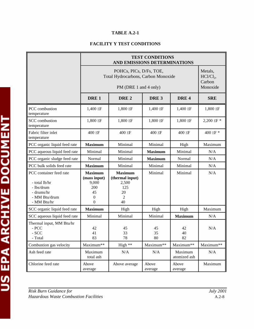
TABLE A.2-1
FACILITY Y TEST CONDITIONS
TEST CONDITIONS AND EMISSIONS DETERMINATIONS
POHCs, PICs, D/Fs, TOE, Total Hydrocarbons, Carbon Monoxide
PM (DRE 1 and 4 only)
Metals,HCl/Cl2,CarbonMonoxide
DRE 1 DRE 2 DRE 3 DRE 4 SRE
PCC combustiontemperature
1,400 EF 1,800 EF 1,400 EF 1,400 EF 1,800 EF
SCC combustiontemperature
1,800 EF 1,800 EF 1,800 EF 1,800 EF 2,200 EF *
Fabric filter inlettemperature
400 EF 400 EF 400 EF 400 EF 400 EF *
PCC organic liquid feed rate Maximum Minimal Minimal High Maximum
PCC aqueous liquid feed rate Minimal Minimal Maximum Minimal N/A
PCC organic sludge feed rate Normal Minimal Maximum Normal N/A
PCC bulk solids feed rate Maximum Minimal Minimal Minimal N/A
PCC container feed rate - total lb/hr - lbs/drum - drums/hr - MM Btu/drum - MM Btu/hr
Maximum(mass input)
9,0002004500
Maximum(thermal input)
2,50012520
240
Minimal Minimal N/A
SCC organic liquid feed rate Maximum High High High Maximum
SCC aqueous liquid feed rate Minimal Minimal Minimal Maximum N/A
Thermal input, MM Btu/hr - PCC - SCC - Total
424183
453378
453580
424082
N/A
Combustion gas velocity Maximum** High ** Maximum** Maximum** Maximum**
Ash feed rate Maximum total ash
N/A N/A Maximumatomized ash
N/A
Chlorine feed rate Aboveaverage
Above average Aboveaverage
Aboveaverage
Maximum
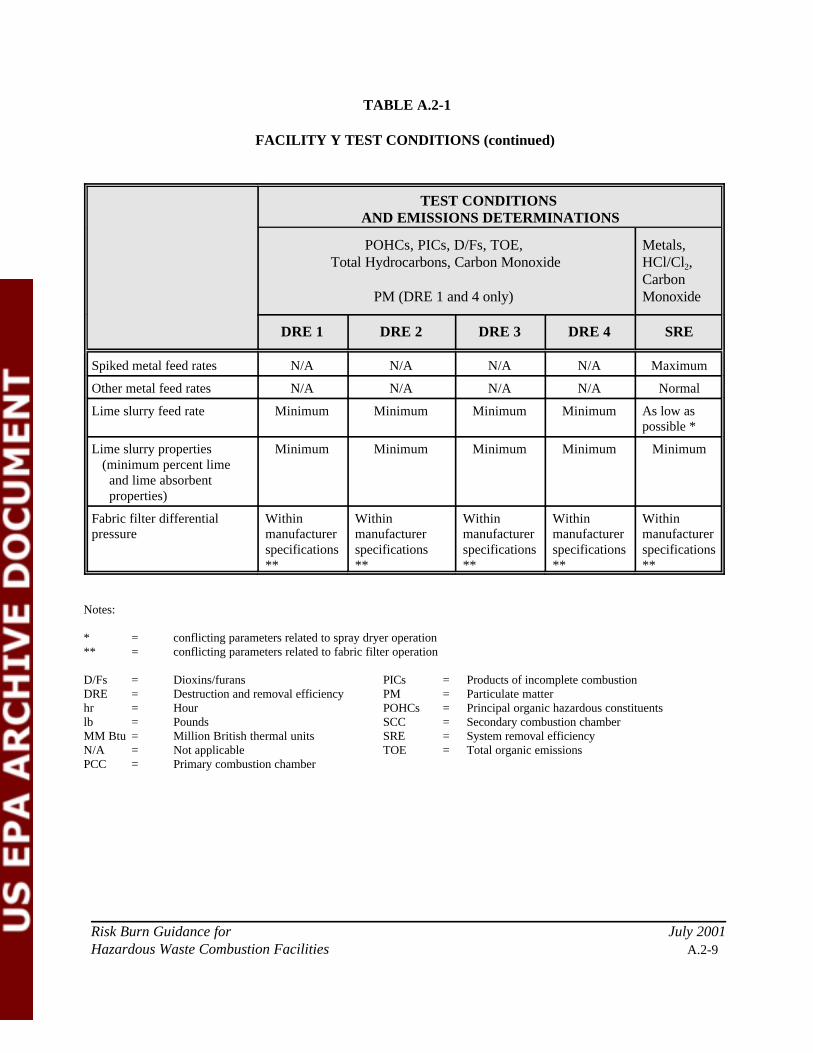
TABLE A.2-1
FACILITY Y TEST CONDITIONS (continued)
TEST CONDITIONS AND EMISSIONS DETERMINATIONS
POHCs, PICs, D/Fs, TOE, Total Hydrocarbons, Carbon Monoxide
PM (DRE 1 and 4 only)
Metals,HCl/Cl2,CarbonMonoxide
DRE 1 DRE 2 DRE 3 DRE 4 SRE
Risk Burn Guidance for July 2001Hazardous Waste Combustion Facilities A.2-9
Spiked metal feed rates N/A N/A N/A N/A Maximum
Other metal feed rates N/A N/A N/A N/A Normal
Lime slurry feed rate Minimum Minimum Minimum Minimum As low aspossible *
Lime slurry properties (minimum percent lime and lime absorbent properties)
Minimum Minimum Minimum Minimum Minimum
Fabric filter differentialpressure
Withinmanufacturerspecifications**
Withinmanufacturerspecifications **
Withinmanufacturerspecifications**
Withinmanufacturerspecifications**
Withinmanufacturerspecifications**
Notes:
* = conflicting parameters related to spray dryer operation** = conflicting parameters related to fabric filter operation
D/Fs = Dioxins/furans PICs = Products of incomplete combustionDRE = Destruction and removal efficiency PM = Particulate matterhr = Hour POHCs = Principal organic hazardous constituentslb = Pounds SCC = Secondary combustion chamberMM Btu = Million British thermal units SRE = System removal efficiencyN/A = Not applicable TOE = Total organic emissionsPCC = Primary combustion chamber

Risk Burn Guidance for July 2001Hazardous Waste Combustion Facilities A.2-10
Site-Specific Risk Assessment
Facility Y performs the tests according to the approved test plan. Emissions data are consolidated from the
test conditions for evaluation in four (4) separate multi-pathway human health and ecological site-specific
risk assessment scenarios corresponding to each of the DRE 1, DRE 2, DRE 3 and DRE 4 test conditions as
follows:
C D/F emissions and organic PIC emissions from each DRE test condition are evaluated,together with . . .
C Metals emissions (18 metals) from the SRE test condition, and . . .
C HCl and Cl2 emissions from the SRE test condition.
Total chronic risks for all four risk scenarios are determined to be below target levels.
An acute risk evaluation is also performed to assess inhalation risks associated with maximum potential one-
hour emissions. Maximum one-hour emissions for the acute evaluation are estimated for D/Fs , other
organics, and HCl/Cl2 based on the test data listed above, with an upward adjustment to reflect upsets.
However, for metals, the test data are not representative of maximum potential one-hour emissions. For the
metals represented by the spiked metals (arsenic, beryllium, cadmium, chromium, and lead), the facility uses
an approved extrapolation procedure to estimate maximum one-hour emission rates based on maximum
anticipated one-hour feed rates and the SREs demonstrated during the testing. The extrapolated emissions
estimates are then adjusted further to reflect upsets. For the remaining metals, the facility estimates
maximum emissions based on maximum anticipated one-hour feed rates and an assumption of zero SRE.
Further upward adjustment for these metals is not necessary, since the “zero SRE” assumption already
represents the most conservative estimate. Acute risks associated with these maximum emissions estimates
are determined to be below target levels.
Finally, Facility Y performs a “post-MACT scenario” chronic risk evaluation. This evaluation is based on
emissions estimates for D/Fs, mercury, semivolatile metals, low-volatile metals, and HCl/Cl2, where
emissions are determined assuming that Facility Y emits at the allowable MACT standard for these
pollutants. These emission estimates are combined with the organic PIC emissions measured during the DRE
Risk Burn Guidance for July 2001Hazardous Waste Combustion Facilities A.2-11
tests, as well as the metals emissions for the non-MACT metals measured during the SRE test. Total chronic
risks from these consolidated emissions are determined to be below target levels.
Final Permitted Emission Rates
As summarized in Table A.2-2, maximum emission rate limits are established in the RCRA permit for D/Fs,
metals, and HCl/Cl2 based on the levels needed to achieve target risk levels. The limits are established for the
purpose of periodic verification testing to ensure that emissions remain below those evaluated in the risk
assessment. If emissions increases occur above the permitted levels, then the permit calls for the risk
assessment to be repeated. Since none of the non-D/F organics were found to be risk drivers, emission limits
for individual non-D/F organic compounds are not established in the permit.
The “post-MACT scenario” risk evaluation showed that the MACT standards for D/Fs, metals, and HCl/Cl2
will be sufficiently protective. Therefore, the RCRA permit includes “sunset” provisions on the emission
limits for these pollutants in the RCRA permit. In this instance, the sunset provisions are structured so that
the RCRA emission limits will no longer apply once the facility has documented compliance with MACT,
and once the regulatory agency has completed a finding of compliance. Emission limits for the non-MACT
metals (aluminum, antimony, barium, cobalt, copper, manganese, nickel, selenium, silver, thallium,
vanadium, and zinc) will remain in the RCRA permit.
Final Permit Limits for Control Parameters
Table A.2-2 provides the final permit limits on relevant control parameters for Facility Y. During the DRE
test conditions, carbon monoxide levels were greater than 100 ppm and total hydrocarbon levels were less
than 10 ppm on an hourly rolling average basis. The permit writer establishes the RCRA permit limit for
carbon monoxide as the average of the test run averages (i.e., a value greater than 100 ppm). Since carbon
monoxide and total hydrocarbon spikes appeared to track pretty closely, the permit writer determines that
there is no need to specify continued total hydrocarbon monitoring as a RCRA permit condition prior to
MACT. However, after MACT, the facility will comply with a total hydrocarbon limit of 10 ppm instead of
with the limit on carbon monoxide.

Risk Burn Guidance for July 2001Hazardous Waste Combustion Facilities A.2-12
With the exception of mercury, quarterly average metals feed rate limits are established in the RCRA permit
based on the feed rates demonstrated during the SRE test. For mercury, a risk-based feed rate limit is
conservatively calculated from the risk-based emission limit by assuming zero SRE (i.e., 100% of the
mercury fed to the unit is emitted).
Short-term metal feed rate limits are not necessary for the RCRA permit, because acute risks were
determined to be negligible (considering the range of inputs for metals at Facility Y). Although the SRE tests
were performed for the purpose of establishing short-term metal feed rate limits for arsenic, beryllium,
cadmium, chromium, and lead, these limits will apply in the future pursuant to MACT and are not a RCRA
concern.
The RCRA permit is written with sunset provisions for all control parameters except for the quarterly
average feed rate limits on the non-MACT metals, and except for limits on containerized feeds which are not
required to be established under the MACT rule. Although MACT will limit total mass feed rate for
containers (as well as total hydrocarbons), the historical operating data for Facility Y suggests that
preventive controls are needed to preclude overcharging of highly volatile, high-Btu containers. Therefore,
the limits on “maximum Btu/drum” and “maximum total containerized thermal input” established based on
the DRE 2 test will be retained in the RCRA permit. The RCRA permit may be modified to delete these
provisions if similar limitations are placed in the Title V permit for this facility in the future.

Risk Burn Guidance for July 2001Hazardous Waste Combustion Facilities A.2-13
TABLE A.2-2
FINAL RCRA PERMIT LIMITS FOR FACILITY Y
Parameter Value
Basis
SunsetTest Established As:
Summary of Performance Standards and Emission Limits
DRE 99.99% for POHCs N/A Regulatory Limit Yes
Maximum PM Emissions 0.08 gr/dscf N/A Regulatory Limit Yes
HCl Larger of 99%removal or 4 lbs/hr
N/A Regulatory Limit Yes
Maximum HCl and Cl2emissions
Inhalation risk-based limits
N/A Target levels from riskassessment
Yes
Maximum D/F emissions Multi-pathwayrisk-based limit
N/A Target level from riskassessment
Yes
Maximum emissions(arsenic, beryllium,cadmium, chromium, leadand mercury)
Multi-pathwayrisk-based limits
N/A Target levels from riskassessment
Yes
Maximum emissions(aluminum, antimony,barium, cobalt, copper,manganese, nickel,selenium, silver, thallium,vanadium, zinc)
Multi-pathwayrisk-based limits
N/A Target levels from riskassessment
No
Group A Control Parameters - Interlocked with AWFCO
Minimum PCCcombustion temperature
1,400 EF, HRA DRE Avg. of the test runaverages
Yes
Minimum SCCcombustion temperature
1,800 EF, HRA DRE Avg. of the test runaverages
Yes
Maximum combustiongas velocity
cfm, HRA DRE/SRE
Avg. of the test runaverages 1
Yes
Maximum PCC organicliquid feed rate
lbs/hr, HRA DRE 1 Avg. of the test runaverages 1
Yes
Maximum PCC aqueousfeed rate
lbs/hr, HRA DRE 3 Avg. of the test runaverages 1
Yes
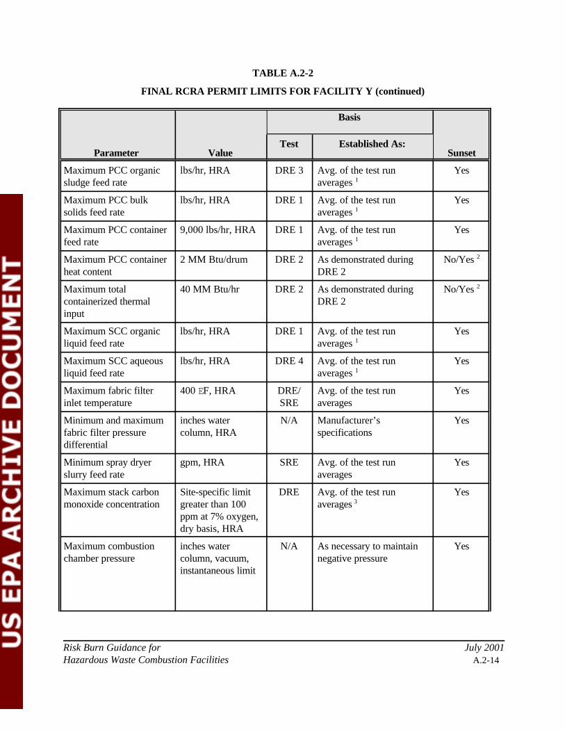
TABLE A.2-2
FINAL RCRA PERMIT LIMITS FOR FACILITY Y (continued)
Parameter Value
Basis
SunsetTest Established As:
Risk Burn Guidance for July 2001Hazardous Waste Combustion Facilities A.2-14
Maximum PCC organicsludge feed rate
lbs/hr, HRA DRE 3 Avg. of the test runaverages 1
Yes
Maximum PCC bulksolids feed rate
lbs/hr, HRA DRE 1 Avg. of the test runaverages 1
Yes
Maximum PCC containerfeed rate
9,000 lbs/hr, HRA DRE 1 Avg. of the test runaverages 1
Yes
Maximum PCC containerheat content
2 MM Btu/drum DRE 2 As demonstrated duringDRE 2
No/Yes 2
Maximum totalcontainerized thermalinput
40 MM Btu/hr DRE 2 As demonstrated duringDRE 2
No/Yes 2
Maximum SCC organicliquid feed rate
lbs/hr, HRA DRE 1 Avg. of the test runaverages 1
Yes
Maximum SCC aqueousliquid feed rate
lbs/hr, HRA DRE 4 Avg. of the test runaverages 1
Yes
Maximum fabric filterinlet temperature
400 EF, HRA DRE/SRE
Avg. of the test runaverages
Yes
Minimum and maximumfabric filter pressuredifferential
inches watercolumn, HRA
N/A Manufacturer’sspecifications
Yes
Minimum spray dryerslurry feed rate
gpm, HRA SRE Avg. of the test runaverages
Yes
Maximum stack carbonmonoxide concentration
Site-specific limitgreater than 100ppm at 7% oxygen,dry basis, HRA
DRE Avg. of the test runaverages 3
Yes
Maximum combustionchamber pressure
inches watercolumn, vacuum,instantaneous limit
N/A As necessary to maintainnegative pressure
Yes
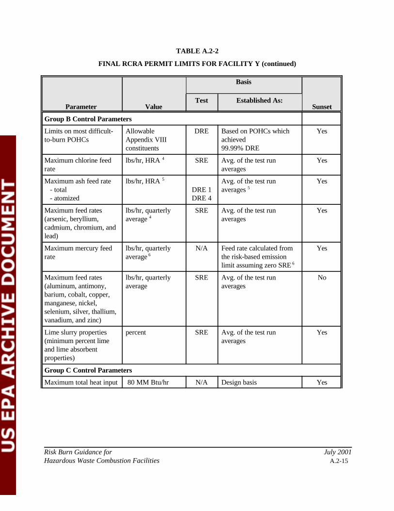
TABLE A.2-2
FINAL RCRA PERMIT LIMITS FOR FACILITY Y (continued)
Parameter Value
Basis
SunsetTest Established As:
Risk Burn Guidance for July 2001Hazardous Waste Combustion Facilities A.2-15
Group B Control Parameters
Limits on most difficult-to-burn POHCs
AllowableAppendix VIIIconstituents
DRE Based on POHCs whichachieved99.99% DRE
Yes
Maximum chlorine feedrate
lbs/hr, HRA 4 SRE Avg. of the test runaverages
Yes
Maximum ash feed rate - total - atomized
lbs/hr, HRA 5
DRE 1DRE 4
Avg. of the test runaverages 5
Yes
Maximum feed rates(arsenic, beryllium,cadmium, chromium, andlead)
lbs/hr, quarterlyaverage 4
SRE Avg. of the test runaverages
Yes
Maximum mercury feedrate
lbs/hr, quarterlyaverage 6
N/A Feed rate calculated fromthe risk-based emissionlimit assuming zero SRE 6
Yes
Maximum feed rates(aluminum, antimony,barium, cobalt, copper,manganese, nickel,selenium, silver, thallium,vanadium, and zinc)
lbs/hr, quarterlyaverage
SRE Avg. of the test runaverages
No
Lime slurry properties(minimum percent limeand lime absorbentproperties)
percent SRE Avg. of the test runaverages
Yes
Group C Control Parameters
Maximum total heat input 80 MM Btu/hr N/A Design basis Yes
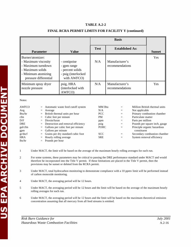
TABLE A.2-2
FINAL RCRA PERMIT LIMITS FOR FACILITY Y (continued)
Parameter Value
Basis
SunsetTest Established As:
Risk Burn Guidance for July 2001Hazardous Waste Combustion Facilities A.2-16
Burner/atomizer:- Maximum viscosity- Maximum turndown- Maximum solids- Minimum atomizing pressure differential
- centipoise- gpm range- percent solids- psig (interlocked with AWFCO)
N/A Manufacturer’srecommendations
Yes
Minimum spray dryernozzle pressure
psig, HRA(interlocked withAWFCO)
N/A Manufacturer’srecommendations
Yes
Notes:
AWFCO = Automatic waste feed cutoff system MM Btu = Million British thermal unitsAvg. = Average N/A = Not applicableBtu/hr = British thermal units per hour PCC = Primary combustion chambercfm = Cubic feet per minute PM = Particulate matterD/F = Dioxin/furan ppm = Parts per millionDRE = Destruction and removal efficiency psig = Pounds per square inch, gaugegal/cfm = Gallons per cubic feet per minute POHC = Principle organic hazardousgpm = Gallons per minute constituentgr/dscf = Grains per dry standard cubic foot SCC = Secondary combustion chamberHRA = Hourly rolling average SRE = System removal efficiencylbs/hr = Pounds per hour
1 Under MACT, the limit will be based on the average of the maximum hourly rolling averages for each run.
2 For some systems, these parameters may be critical to passing the DRE performance standard under MACT and wouldtherefore be incorporated into the Title V permit. If these limitations are placed in the Title V permit, then theprovisions may be sunset or deleted from the RCRA permit.
3 Under MACT, total hydrocarbon monitoring to demonstrate compliance with a 10 ppmv limit will be performed insteadof carbon monoxide monitoring.
4 Under MACT, the averaging period will be 12 hours.
5 Under MACT, the averaging period will be 12 hours and the limit will be based on the average of the maximum hourlyrolling averages for each run.
6 Under MACT, the averaging period will be 12 hours and the limit will be based on the maximum theoretical emissionconcentration assuming that all mercury from all feed streams is emitted.