Embed Size (px)
Citation preview
Prepared By RADIAN Corp. . . . . . . . . . . . . . . . . . . . . . . . . . . . . . . . . . . . . . . . . . . . . . . . . . . Task 650-124-01-51
APPENDIX A
EMISSIONS ESTIMATION
A-1 Computational Approach
A-2 Sample Calculations
A-3 Determination of Emission Factors for Engines and Turbines
A-4 Emission Factor Tables
Columbia Gas Transmission Corporation . . . . . . . . . . . . . . . . . . . . . . . . . . . . . . . . . . . . . . . . . . . . . Title V Project
Prepared By RADIAN Corp. . . . . . . . . . . . . . . . . . . . . . . . . . . . . . . . . . . . . . . . . . . . . . . . . . . Task 650-124-01-51
A-1 Computational Approach
Columbia Gas Transmission Corporation . . . . . . . . . . . . . . . . . . . . . . . . . . . . . . . . . . . . . . . . . . . . . Title V Project
sdg/N-OH-d-grams Revision 1Appendix A/ October 12, 1995A.1- 1
A-1 COMPUTATIONAL APPROACH
A computerized database and spreadsheet have been developed to standardize datahandling and emissions calculations. The database provides a central location for equipmentinventory data and ensures a consistent emissions estimation approach for all equipment at allOhio facilities. This section describes the approach taken in the database for estimating emissions.Section A-2 provides sample calculations and Section A-3 provides the method used fordetermining emission factors for engines and turbines. Section A-4 lists emission factors fordifferent equipment and the basis of deriving these factors.
A-1.1 Prime Mover Combustion Turbines
A compressor turbine package is a complex mechanical system of interrelated unitoperations. The main units are the turbine driver and gas compressor. Supporting units includelubrication and sealant systems.
The driver system is a multistage stationary combustion turbine burning natural gas as fuel.The turbine propels a centrifugal compressor which is used to pump natural gas throughdistribution pipelines.
The supporting systems include pumps that are used to maintain fluid pressure and flowand tanks that are used for intermediate storage of lubrication and sealant fluids, as well asproviding pump volume and pump head. Breathing vents used to equalize internal pressures arecommon. Demisters and other devices to separate entrained oil mist from air are integrated intothe system. Most turbines also include a gas-driven starter to initiate turbine spin prior to start-upignition. Depending on the manufacturer's design and the package's construction date, the systemtanks and pumps may or may not be visible; however, all of these components are present.
The main emissions from a turbine package are from the combustion exhaust. Thecombustion emissions are estimated using emissions factors identified in literature (AP-42, GRI-HAPCalc™) or developed from test results and manufacturers' data. These emission factors arein the form of gram pollutant per horsepower-hour. Potential emissions are calculated based oncontinuous operation (8,760 hour/year) at rated horsepower. During winter operation, these unitsfrequently operate at greater than nameplate horsepower due to the impact of cold, densecombustion air on turbine performance. Therefore, any short-term emission estimates arecalculated using maximum achievable horsepower for the turbine, which is calculated using therated horsepower for the turbine and an operational variance factor. Actual emissions areestimated using recorded operating brake horsepower-hours for the last year and assuming thatthe turbine operates at its rated capacity.
Emissions from the supporting systems are extremely small. The compressor oil seal ventis an insignificant emission point. The main release from the compressor seal is slight amountsof VOCs from the natural gas leakage passing through the seal. Lubrication oil vents and othersimilar vents are also insignificant emission points. Lubrication oils are highly refined, heavyhydrocarbons with extremely low vapor pressure (<10-6 torr) and create insignificant emissions.
Columbia Gas Transmission Corporation . . . . . . . . . . . . . . . . . . . . . . . . . . . . . . . . . . . . . . . . . . . . . Title V Project
sdg/N-OH-d-grams Revision 1Appendix A/ October 12, 1995A.1- 2
Compressor seal emissions are included as part of the plant fugitive loss calculation in accordancewith EPA document EPA 453/R-93-026, published in June 1993.
Blowdown vents for the compressor unit are necessary for reducing system pressure formaintenance purposes, engine shutdown, or in case of emergency. Emissions due to unitblowdown and the turbine starter are included in the plant fugitive loss calculation.
A-1.2 Internal Combustion Compressor Engines and Auxiliary Engines
An internal combustion (IC) compressor engine package is a complex mechanical systemof interrelated unit operations. The main units are the IC engine driver and gas compressor.Supporting units include coolant, lubrication, and sealant systems. Auxiliary engines include thesame components with the possible exception of a compressor.
The driver system is a stationary internal combustion engine of either 2- or 4-cycle design.This unit provides the power to drive a reciprocating or centrifugal compressor which pumpsnatural gas through distribution pipelines. Auxiliary engines are typically used to drive aircompressors or to generate station power in the event of an electrical grid outage.
The supporting systems include pumps that are used to maintain fluid pressure and flow,and tanks that are used for intermediate storage of coolant, lubrication, and sealant fluids. Bothair- and fluid-cooled heat exchangers are common. Breathing vents used to equalize internalpressures are also common. Depending on the manufacturer's design and the overall stationlayout, the system tanks and pumps may be dedicated to individual engines or shared betweenseveral.
The main emissions from a compressor engine package are from the combustion exhaust.The combustion emissions are estimated using emissions factors identified in literature (AP-42,GRI-HAPCalc™) or developed from test results and manufacturers' data. These emission factorsare in the form of gram pollutant per horsepower-hour. Unless otherwise stated, annual potentialemissions are calculated based on continuous operation (8,760 hour/year) at rated horsepower.Depending on pipeline conditions, these units may operate at greater than nameplate horsepower.Therefore, any short-term maximum emission estimates are calculated using maximum achievablehorsepower, which is calculated using the rated horsepower of the engine and an operationalvariance factor.
Actual emissions from auxiliary engines are based on actual hours of operation as loggedby the station and rated unit horsepower using emission factors identified in literature (AP-42,GRI-HAPCalc™) or developed from manufacturer's data. Unless otherwise noted, annualpotential emissions are based on continuous operation (8,760 hr/yr) at rated unit horsepower.Short-term maximum emission estimates are calculated using maximum achievable horsepower,which is calculated using the rated horsepower of the engine and an operational variance factor.
Emissions from the supporting subsystems are extremely small. Units have a crankcaseoil vent that is an insignificant emissions point. The main release from the compressor seal isslight amounts of VOCs from the natural gas leakage passing through the seal. Lubrication oil
Columbia Gas Transmission Corporation . . . . . . . . . . . . . . . . . . . . . . . . . . . . . . . . . . . . . . . . . . . . . Title V Project
sdg/N-OH-d-grams Revision 1Appendix A/ October 12, 1995A.1- 3
vents, coolant fluid, and other similar vents are insignificant emission points. The coolant is awater-glycol mixture with insignificant VOC vapor pressure. Emissions from the compressor sealare included as part of the plant fugitive loss calculation in accordance with EPA documentEPA 453/R-93-026, published in June 1993.
Blowdown vents for the compressor unit are necessary for reducing system pressure formaintenance purposes, engine shutdowns, or in case of emergency. Emissions due to unitblowdown are included in the plant fugitive loss calculation.
A-1.3 Gas-Fired Heaters, Boilers, and Other Combustion Sources
Since CGT facilities are gas transmission stations, external combustion sources are naturalgas-fired and are generally less than 10 million Btu/hr (MMBtu/hr) capacity. These sourcesinclude process heaters, fuel gas heaters, reboilers, and space heaters. They operate on an "asneeded" basis and generally achieve significantly less than 8,760 hours per year.
Emissions are estimated using literature-based factors (AP-42 and GRI-HAPCalc™)expressed in lb pollutant per MMBtu. Although typical operation is at less than full capacity, thepotential-to-emit is computed on full rated capacity at 8,760 hours/year. Actual emissions areestimated at full rated capacity for the actual operating hours in a given year. Since most of theseunits operate "on-demand," they are generally not at full rated capacity unless the weatherconditions are extreme. Therefore, the calculated actual emission estimates overstate the realactual emissions from these units. However, since these units are extremely small compared withthe station's prime movers, their impact on total station emissions is generally small (<1%).
Space heaters, most hot water boilers, and small fuel gas heaters (catalytic heaters) lessthan 4 MMBtu/hr meet the OEPA Engineering Guide #62 “trivial” definition. The majority ofheaters at Ohio stations meet this definition. They are not incorporated into the Title V permitapplication.
A-1.4 Atmospherically Vented Storage Tanks
Since CGT stations are primarily gas transmission stations, storage tanks are generallylimited in size and scope. Storage tanks are subordinate support systems to the main process.This situation lends itself to a series of simplifying assumptions and determinations to produce arelatively simple worst-case estimation technique following the methods presented in AP-42. AtCGT’s Ohio stations, almost all tanks meet the OEPA Engineering Guide #62 “trivial” definition.Those that are not trivial are insignificant.
Columbia Gas Transmission Corporation . . . . . . . . . . . . . . . . . . . . . . . . . . . . . . . . . . . . . . . . . . . . . Title V Project
sdg/N-OH-d-grams Revision 1Appendix A/ October 12, 1995A.1- 4
A-1.5 Fugitive Emission Sources
Fugitive emissions from stations are trivial VOC sources in accordance with OEPAEngineering Guide #62. A station leak point survey has been performed following the proceduresoutlined in EPA-453/R-93-026, June 1993, "Protocol for Equipment Leak Emission Estimates,"specifically Section 2.3.1 and Table 2-3. Stations are small enough that the whole station mustbe evaluated to have a statistically valid number of valves and other identifiable leak points.
Fugitive emissions generally include emissions that are not directly affected by systemoperations and are not emitted through a stack or functionally equivalent vent. For example,leakage from valves, flanges, compressors, and pump seals are considered fugitive losses. Airpollution regulations have traditionally included leakage from pressure relief devices and productaccumulator vessels as fugitives; although, these items typically emit via vents or stacks. For thepurpose of estimating emissions from a facility, transitional losses (such as blowdowns) andmiscellaneous equipment leaks (such as pipeline valves) are included in the fugitive emissionsestimate.
The main fugitive emission points are:
C gas piping system leaks;C compressor seal leaks;C unit blowdown losses; andC station blowdown losses.
Minor fugitive emission points are:
C lubrication oil, seal oil, and coolant systems; andC losses during pipeline and process equipment maintenance; andC operation of miscellaneous gas-driven yard valves.
Losses from the main fugitive emission points are used to estimate fugitive emissions for thefacility.
The EPA protocol provides methods for estimating emissions using average emissionfactors for leakage from valves, connectors, pressure relief valves, and compressor seals. Theprocedure requires a station-wide count of the individual items. The emission factors arestatistically based averages for a large population and cannot be used to predict a given item'semissions.
Volumetric losses from a unit blowdown and restart are relatively constant for eachshutdown-startup sequence of a given unit. Emissions are estimated based on the estimatedshutdowns per year, the average blowdown pressure, and the volume of piping and vessels whichare blown down in each sequence.
A-1.6 Glycol Dehydrators and LPG Extractors
Columbia Gas Transmission Corporation . . . . . . . . . . . . . . . . . . . . . . . . . . . . . . . . . . . . . . . . . . . . . Title V Project
sdg/N-OH-d-grams Revision 1Appendix A/ October 12, 1995A.1- 5
Glycol dehydrators are used to remove water from natural gas and to prevent hydrateformation and corrosion. The basic design of a glycol dehydrator includes an absorber tower,where the natural gas is contacted counter-currently with glycol. Water in the gas is absorbed bythe glycol, and the dry gas is discharged to the compression area of the station. The rich (wet)glycol is piped to a regeneration still, where the absorbed water is distilled from the glycol. Thestill has an associated reboiler which combusts natural gas to provide heat for the glycoldistillation.
LPG extractors operate on similar physical phenomena as a dehydrator. Glycol is injectedinto the wet gas stream which is then cooled by a multistage heat exchanger to between -10°F and-20°F. A three-phase system results: dry gas, an organic phase (liquefied petroleum gas) and wetglycol. The phases are separated. The glycol is regenerated in a still and recycled.
In addition to removing water from natural gas, the dehydration and LPG extractionprocesses remove some benzene, toluene, ethylbenzene, and xylene (BTEX) and other VOC fromthe natural gas. These hydrocarbons are separated from the glycol in the regenerator still andemitted to the atmosphere. The GRI-GlyCalc™ model developed by the Gas Research Institute(GRI) was used to estimate emissions of BTEX and other VOC from regeneration stills.Emissions from the reboiler were calculated following the procedure described in Section A-1.3for heaters and boilers.
GRI-GlyCalc™ uses a combination of mass transfer theory and empirical data to estimateemissions with the following procedure: (1) a water balance around the absorber is performed;(2) absorption factors for all compounds are calculated using the UNIQUAC activity coefficientmodel and the Peng-Robinson equation of state; (3) the amount of each compound absorbed bythe glycol in the contactor is calculated using the Kremser-Brown approximation; (4) if a flashtank is present, a standard temperature-pressure flash calculation is performed to estimate howmuch of each compound is flashed out of the rich glycol; (5) the amount of each compoundemitted from the regenerator is estimated by a mass balance, assuming the regenerated glycolcontains very little BTEX or other hydrocarbons.
The primary inputs for GRI-GlyCalc™ are the conditions of the inlet natural gas (flow rate,composition, pressure, and temperature), the conditions of the lean glycol (circulation rate andcomposition), the dry gas water content, and the number of equilibrium stages in the contactor.For systems that have a flash tank, the flash temperature and pressure are required. To estimatepotential emissions, continuous operation at the unit design gas throughput is assumed. Actualannual emissions are based on average annual operating hours and actual operating parameters.
Columbia Gas Transmission Corporation . . . . . . . . . . . . . . . . . . . . . . . . . . . . . . . . . . . . . . . . . . . . . Title V Project
APPENDIX A-2
SAMPLE CALCULATIONS
Columbia Gas Transmission Corporation . . . . . . . . . . . . . . . . . . . . . . . . . . . . . . . . . . . . . . . . . . . . . Title V Project
sdg/cgt-OH Revision 1Appendix A September 28, 1995A.2-1
A-2 SAMPLE CALCULATIONS
This section presents a generic sample calculation and explanatory discussion for thefollowing equipment items:
C Internal combustion engines and turbinesC Gas-fired boilersC Gas-fired process heatersC Atmospherically vented storage tanksC Glycol dehydratorsC Fugitive emission sources
The basis for the determination of emission factors is discussed in Appendix A-3, Determinationof Emission Factors for Engines and Turbines. The emission factors, with references, are listedin Appendix A-4 as Tables A-4.1, A-4-2, and A-4.3. The operational variance factors are listedin Tables A-4.4.
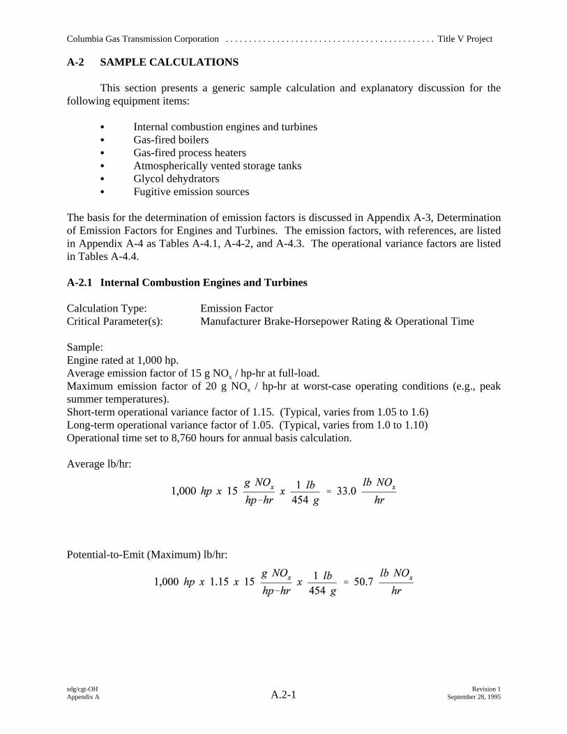
A-2.1 Internal Combustion Engines and Turbines
Calculation Type: Emission FactorCritical Parameter(s): Manufacturer Brake-Horsepower Rating & Operational Time
Sample:Engine rated at 1,000 hp.Average emission factor of 15 g NOx / hp-hr at full-load.Maximum emission factor of 20 g NOx / hp-hr at worst-case operating conditions (e.g., peaksummer temperatures).Short-term operational variance factor of 1.15. (Typical, varies from 1.05 to 1.6) Long-term operational variance factor of 1.05. (Typical, varies from 1.0 to 1.10)Operational time set to 8,760 hours for annual basis calculation.
Average lb/hr:
Potential-to-Emit (Maximum) lb/hr:
Columbia Gas Transmission Corporation . . . . . . . . . . . . . . . . . . . . . . . . . . . . . . . . . . . . . . . . . . . . . Title V Project
sdg/cgt-OH Revision 1Appendix A September 28, 1995A.2-2
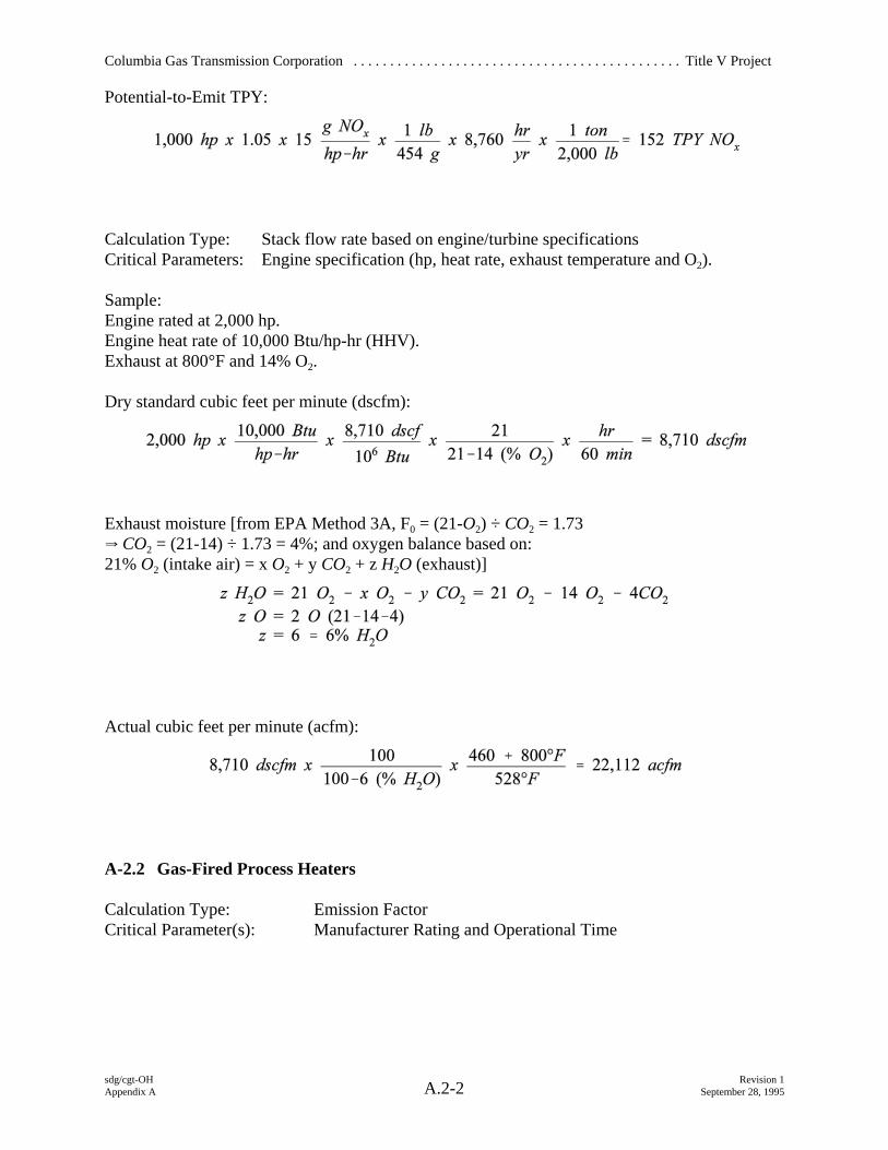
Potential-to-Emit TPY:
Calculation Type: Stack flow rate based on engine/turbine specificationsCritical Parameters: Engine specification (hp, heat rate, exhaust temperature and O2).
Sample:Engine rated at 2,000 hp.Engine heat rate of 10,000 Btu/hp-hr (HHV).Exhaust at 800°F and 14% O2.
Dry standard cubic feet per minute (dscfm):
Exhaust moisture [from EPA Method 3A, F0 = (21-O2) ÷ CO2 = 1.73 Y CO2 = (21-14) ÷ 1.73 = 4%; and oxygen balance based on:21% O2 (intake air) = x O2 + y CO2 + z H2O (exhaust)]
Actual cubic feet per minute (acfm):
A-2.2 Gas-Fired Process Heaters
Calculation Type: Emission FactorCritical Parameter(s): Manufacturer Rating and Operational Time
Columbia Gas Transmission Corporation . . . . . . . . . . . . . . . . . . . . . . . . . . . . . . . . . . . . . . . . . . . . . Title V Project
sdg/cgt-OH Revision 1Appendix A September 28, 1995A.2-3
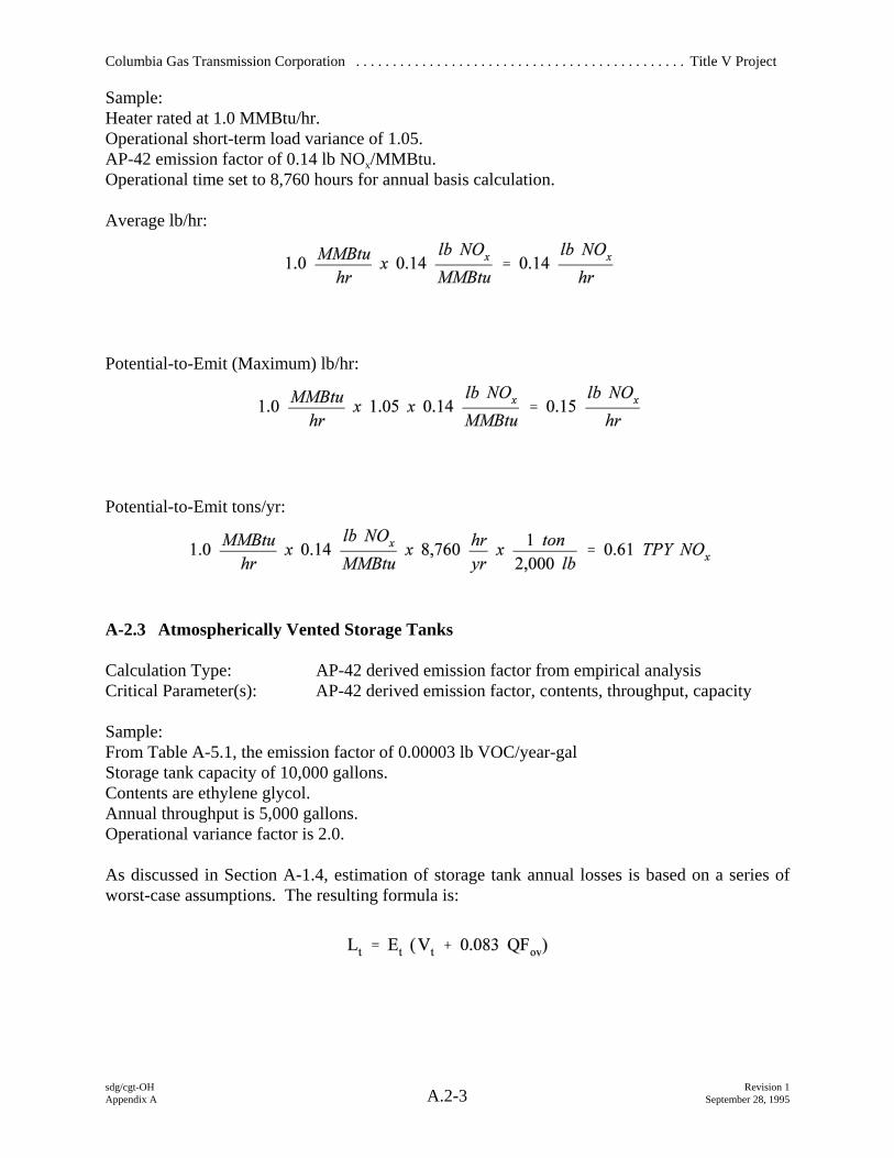
Sample:Heater rated at 1.0 MMBtu/hr.Operational short-term load variance of 1.05.AP-42 emission factor of 0.14 lb NOx/MMBtu.Operational time set to 8,760 hours for annual basis calculation.
Average lb/hr:
Potential-to-Emit (Maximum) lb/hr:
Potential-to-Emit tons/yr:
A-2.3 Atmospherically Vented Storage Tanks
Calculation Type: AP-42 derived emission factor from empirical analysis Critical Parameter(s): AP-42 derived emission factor, contents, throughput, capacity
Sample:From Table A-5.1, the emission factor of 0.00003 lb VOC/year-galStorage tank capacity of 10,000 gallons.Contents are ethylene glycol.Annual throughput is 5,000 gallons.Operational variance factor is 2.0.
As discussed in Section A-1.4, estimation of storage tank annual losses is based on a series ofworst-case assumptions. The resulting formula is:
Columbia Gas Transmission Corporation . . . . . . . . . . . . . . . . . . . . . . . . . . . . . . . . . . . . . . . . . . . . . Title V Project
sdg/cgt-OH Revision 1Appendix A September 28, 1995A.2-4
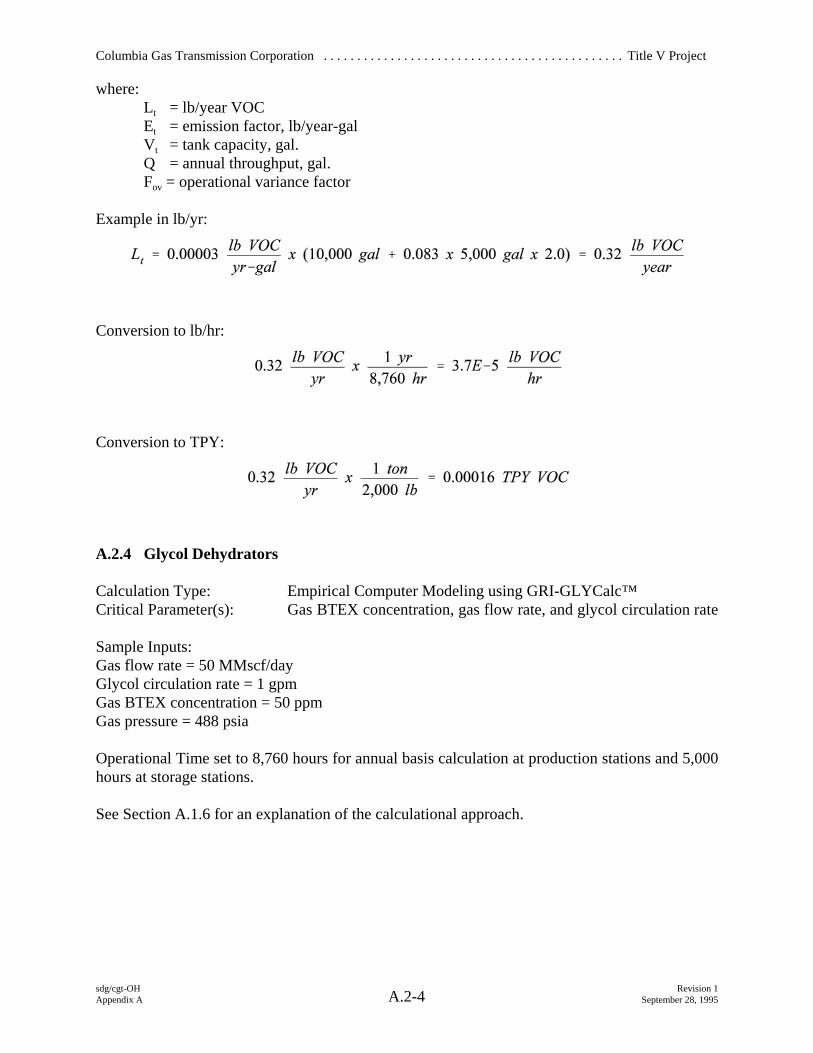
where:Lt = lb/year VOCEt = emission factor, lb/year-galVt = tank capacity, gal.Q = annual throughput, gal.Fov = operational variance factor
Example in lb/yr:
Conversion to lb/hr:
Conversion to TPY:
A.2.4 Glycol Dehydrators
Calculation Type: Empirical Computer Modeling using GRI-GLYCalc™Critical Parameter(s): Gas BTEX concentration, gas flow rate, and glycol circulation rate
Sample Inputs:Gas flow rate = 50 MMscf/dayGlycol circulation rate = 1 gpmGas BTEX concentration = 50 ppmGas pressure = 488 psia
Operational Time set to 8,760 hours for annual basis calculation at production stations and 5,000hours at storage stations.
See Section A.1.6 for an explanation of the calculational approach.
Columbia Gas Transmission Corporation . . . . . . . . . . . . . . . . . . . . . . . . . . . . . . . . . . . . . . . . . . . . . Title V Project
sdg/cgt-OH Revision 1Appendix A September 28, 1995A.2-5
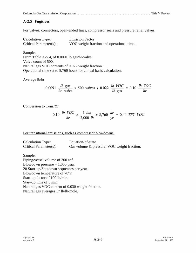
A-2.5 Fugitives
For valves, connectors, open-ended lines, compressor seals and pressure relief valves.
Calculation Type: Emission FactorCritical Parameter(s): VOC weight fraction and operational time.
Sample:From Table A-5.4, of 0.0091 lb gas/hr-valve.Valve count of 500.Natural gas VOC contents of 0.022 weight fraction.Operational time set to 8,760 hours for annual basis calculation.
Average lb/hr:
Conversion to Tons/Yr:
For transitional emissions, such as compressor blowdowns.
Calculation Type: Equation-of-stateCritical Parameter(s): Gas volume & pressure, VOC weight fraction.
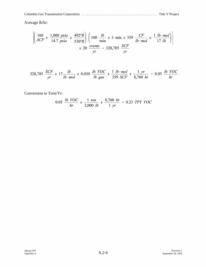
Sample:Piping/vessel volume of 200 acf.Blowdown pressure = 1,000 psia.20 Start-up/Shutdown sequences per year.Blowdown temperature of 70oF.Start-up factor of 100 lb/min.Start-up time of 3 min.Natural gas VOC content of 0.030 weight fraction.Natural gas averages 17 lb/lb-mole.
Columbia Gas Transmission Corporation . . . . . . . . . . . . . . . . . . . . . . . . . . . . . . . . . . . . . . . . . . . . . Title V Project
sdg/cgt-OH Revision 1Appendix A September 28, 1995A.2-6
Average lb/hr:
Conversion to Tons/Yr:
Columbia Gas Transmission Corporation . . . . . . . . . . . . . . . . . . . . . . . . . . . . . . . . . . . . . . . . . . . . . Title V Project
APPENDIX A-3
DETERMINATION OF EMISSION FACTORS FOR ENGINES AND TURBINES
Columbia Gas Transmission Corporation . . . . . . . . . . . . . . . . . . . . . . . . . . . . . . . . . . . . . . . . . . . . . Title V Project
sdg/cgt-OH Revision 1Appendix A September 28, 1995A.3-1
A-3 DETERMINATION OF EMISSION FACTORS FOR ENGINES AND TURBINES
Criteria pollutant emission factors for specific models of engines and turbines weredeveloped where stack test data were available. These tests typically measured NOx and COemissions at the highest available operating load for a given engine or turbine. The test load wasnot necessarily the rated load of the unit due to ambient effects and limitations in gas demandduring testing. Where test data were not available (generally for units rated less than 700 BHPand for VOC), AP-42 emission factors were used. Emission factors from the Gas ResearchInstitute's (GRI) HAPCalc™ were used to estimate the emissions of hazardous air pollutants(HAP's) from each engine. These emission factors are more current than those listed in AP-42.
The available test data were compiled for each engine or turbine model and evaluated ona g/bhp-hr basis to determine average and maximum emissions for the models that had beentested. The test data collected by Columbia reflect engine operating and ambient conditions at thetime of the testing. However, emission rates are very sensitive to the impact of engine operatingand ambient conditions on the engine's air-to-fuel ratio. For example, air-to-fuel ratio andemissions can vary significantly with changes in ambient air temperature; if the testing wasconducted during the winter, an emission factor based on these data may not accurately estimateemissions from the engine when operating during the summer.
The three most important parameters impacting NOx from a normally operating engine areload (bhp), speed (rpm), and ambient temperature. To account for the impact of these parameterson emissions, they were converted into an emissions parameter (EP) defined as:
where ambient temperature is in °R. The EP and emission rate (ER) data (in g/bhp-hr) for eachengine emissions test were then statistically analyzed using linear regression. The form of theregression equation is:
where Co and C1 are statistically derived constants. The measured ER during each test is thencompared to the predicted ER using the above regression equation to (1) identify any data thatmay be suspect and any engines that may not be operating normally, and (2) to assess the normalvariability in emission rates for similar engines.
The ER equation is then used to develop a rated ER and a maximum ER. The rated ER isthe predicted emission rate for the engine when operating at 100% of rated bhp and rpm and anambient temperature of 70°F. The rated ER reflects average
Columbia Gas Transmission Corporation . . . . . . . . . . . . . . . . . . . . . . . . . . . . . . . . . . . . . . . . . . . . . Title V Project
sdg/cgt-OH Revision 1Appendix A September 28, 1995A.3-2
emission rates during a year and is used to estimate an engine's actual and potential annualemissions.
The maximum ER is the predicted emission rate for the engine when operating duringsevere conditions. To account for potential measurement errors and for variability in emissionsamong individual engines of the same model, the difference between the actual and predicted ERfor each tested engine was calculated and the standard deviation of these differences wasdetermined. The maximum ER for NOx is the predicted ER at maximum operating conditions of105% of rated bhp, 100% of rated speed, and 100°F ambient temperature, plus three times thestandard deviation of the differences between actual and predicted NOx. The maximum ER forCO is based on 100% of rated bhp and rpm, and 30°F ambient temperature. The maximum ERis used to estimate the engine's maximum short-term emissions. If this approach was used todetermine rated and maximum ERs for any of the engines at this station; the test data andstatistical analysis results are presented in Appendix F. For engines and turbines that do not havesufficient information to support a statistical analysis of emission factor variability, averageemission factors were adjusted by a factor of two to differentiate between maximum and ratedemissions. This approach was used with data obtained from AP-42 or GRI-HAPCalc™, forengine and turbine models with limited test data, and for estimating VOC emissions.
The emission factors presented in Table A.5-1 and A.5-2 of Appendix A-5 are multipliedby an operating rate to determine mass emission rates for pollutants. For estimating annual oraverage emissions, the operating rate is determined by the manufacturer's power rating (in bhp)and the hours of operation.
Just as ambient conditions impact emissions characteristics, they also influence poweroutput. Combustion turbines generally operate at a set volume (rather than mass) of air input tothe combustion chamber. As ambient temperatures go down, the air becomes more dense, therebyallowing more air mass to be drawn into the combustion chamber. The combustor controlsautomatically adjust fuel flow to maintain the set air-to-fuel ratio required for efficient combustionand to protect turbine materials from damage due to overheating. The net result is that turbinesoperate above the manufacturer's standard condition power output rating during periods of coldweather. Similarly, turbines frequently operate at less than the manufacturer's standard conditionpower output rating during periods of hot weather. In either case, the turbine is operating on itsmanufacturer's design power curve and does not exceed its adjusted rating. Based on datacollected from station logs and personnel, the turbines in the CGT system can operate as much as60 percent above rating during the winter periods. To estimate maximum short-term massemission rates, the operating rate is determined by multiplying the manufacturer's standardcondition power output rating by an operational variance factor to account for non-standardconditions. The operational variance factor varies depending on manufacturer/model and rangesfrom 1.15 to 1.60.
IC engines tend to be less sensitive to ambient impacts on power output; however, they dooccasionally operate above the manufacturer's standard condition rating. To account for thesesperiods of increased power output, engine operating rates are based on the manufacturer's standardcondition rating multiplied by 1.1 to estimate short-term mass emission rates.
Columbia Gas Transmission Corporation . . . . . . . . . . . . . . . . . . . . . . . . . . . . . . . . . . . . . . . . . . . . . Title V Project
APPENDIX A-4
EMISSION FACTOR TABLES
Columbia Gas Transmission Corporation . . . . . . . . . . . . . . . . . . . . . . . . . . . . . . . . . . . . . . . . . . . . . Title V Project
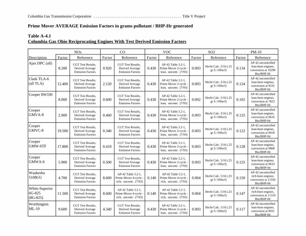
Prime Mover AVERAGE Emission Factors in grams pollutant / BHP-Hr generated
Table A-4.1Columbia Gas Ohio Reciprocating Engines With Test Derived Emission Factors
NOx CO VOC SO2 PM-10Description Factor Reference Factor Reference Factor Reference Factor Reference Factor ReferenceAjax DPC (all)
8.200CGT Test Results, Derived AverageEmission Factors
0.920CGT Test Results, Derived AverageEmission Factors
0.430AP-42 Table 3.2-1,
Prime Mover 2-cycle -lean, uncontr. (7/93)
0.003 Hecht Calc. 5/16 (.25gr S /100scf) 0.134
AP-42 uncontrolledlean-burn engines,
conversion at 10290Btu/BHP-Hr
Clark TLA-6 (all TLA) 12.400
CGT Test Results, Derived AverageEmission Factors
2.120CGT Test Results, Derived AverageEmission Factors
0.430AP-42 Table 3.2-1,
Prime Mover 2-cycle -lean, uncontr. (7/93)
0.003 Hecht Calc. 5/16 (.25gr S /100scf) 0.124
AP-42 uncontrolledlean-burn engines,conversion at 9531
Btu/BHP-Hr
Cooper 8W3308.000
CGT Test Results, Derived AverageEmission Factors
0.600CGT Test Results, Derived AverageEmission Factors
0.430AP-42 Table 3.2-1,
Prime Mover 2-cycle -lean, uncontr. (7/93)
0.002 Hecht Calc. 5/16 (.25gr S /100scf) 0.102
AP-42 uncontrolledlean-burn engines,conversion at 7823
Btu/BHP-Hr
CooperGMVA-8 2.900
CGT Test Results, Derived AverageEmission Factors
0.460CGT Test Results, Derived AverageEmission Factors
0.430AP-42 Table 3.2-1,
Prime Mover 2-cycle -lean, uncontr. (7/93)
0.003 Hecht Calc. 5/16 (.25gr S /100scf) 0.125
AP-42 uncontrolledlean-burn engines,conversion at 9616
Btu/BHP-Hr
CooperGMVC-8 19.500
CGT Test Results, Derived AverageEmission Factors
0.340CGT Test Results, Derived AverageEmission Factors
0.430AP-42 Table 3.2-1,
Prime Mover 2-cycle -lean, uncontr. (7/93)
0.003 Hecht Calc. 5/16 (.25gr S /100scf) 0.122
AP-42 uncontrolledlean-burn engines,conversion at 9418
Btu/BHP-Hr
CooperGMW-6TF 17.800
CGT Test Results, Derived AverageEmission Factors
0.410CGT Test Results, Derived AverageEmission Factors
0.430AP-42 Table 3.2-1,
Prime Mover 2-cycle -lean, uncontr. (7/93)
0.003 Hecht Calc. 5/16 (.25gr S /100scf) 0.128
AP-42 uncontrolledlean-burn engines,conversion at 9868
Btu/BHP-Hr
CooperGMWA-6 5.900
CGT Test Results, Derived AverageEmission Factors
0.500CGT Test Results, Derived AverageEmission Factors
0.430AP-42 Table 3.2-1,
Prime Mover 2-cycle -lean, uncontr. (7/93)
0.003 Hecht Calc. 5/16 (.25gr S /100scf) 0.125
AP-42 uncontrolledlean-burn engines,conversion at 9633
Btu/BHP-Hr
Waukesha5108GU 4.700
CGT Test Results, Derived AverageEmission Factors
8.600AP-42 Table 3.2-1,
Prime Mover 4-cycle -rich, uncontr. (7/93)
0.140AP-42 Table 3.2-1,
Prime Mover 4-cycle -rich, uncontr. (7/93)
0.004 Hecht Calc. 5/16 (.25gr S /100scf) 0.150
AP-42 uncontrolledrich-burn engines,
conversion at 11556Btu/BHP-Hr
White-Superior6G-825(8G-825)
11.500CGT Test Results, Derived AverageEmission Factors
8.600AP-42 Table 3.2-1,
Prime Mover 4-cycle -rich, uncontr. (7/93)
0.140AP-42 Table 3.2-1,
Prime Mover 4-cycle -rich, uncontr. (7/93)
0.004 Hecht Calc. 5/16 (.25gr S /100scf) 0.147
AP-42 uncontrolledrich-burn engines,
conversion at 11319Btu/BHP-Hr
WorthingtonML-10 9.600
CGT Test Results, Derived AverageEmission Factors
4.340CGT Test Results, Derived AverageEmission Factors
0.430AP-42 Table 3.2-1,
Prime Mover 2-cycle -lean, uncontr. (7/93)
0.003 Hecht Calc. 5/16 (.25gr S /100scf) 0.117
AP-42 uncontrolledlean-burn engines,conversion at 9031
Btu/BHP-Hr
Columbia Gas Transmission Corporation . . . . . . . . . . . . . . . . . . . . . . . . . . . . . . . . . . . . . . . . . . . . . Title V Project
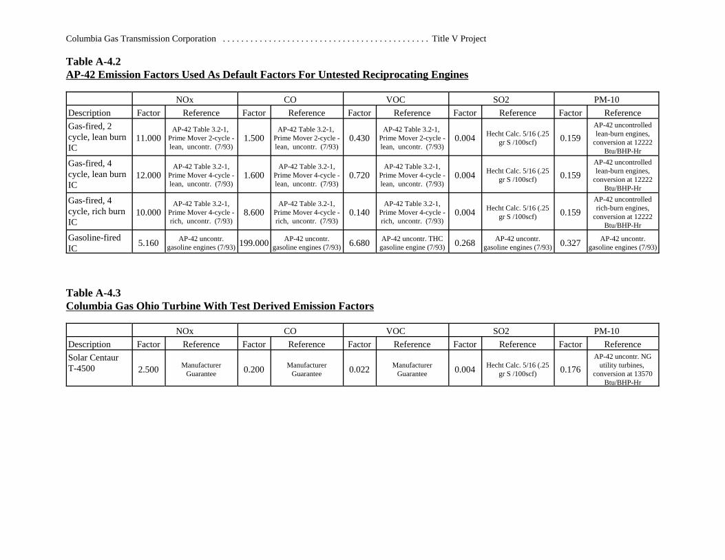
Table A-4.2AP-42 Emission Factors Used As Default Factors For Untested Reciprocating Engines
NOx CO VOC SO2 PM-10Description Factor Reference Factor Reference Factor Reference Factor Reference Factor ReferenceGas-fired, 2cycle, lean burnIC
11.000AP-42 Table 3.2-1,
Prime Mover 2-cycle -lean, uncontr. (7/93)
1.500AP-42 Table 3.2-1,
Prime Mover 2-cycle -lean, uncontr. (7/93)
0.430AP-42 Table 3.2-1,
Prime Mover 2-cycle -lean, uncontr. (7/93)
0.004 Hecht Calc. 5/16 (.25gr S /100scf) 0.159
AP-42 uncontrolledlean-burn engines,
conversion at 12222Btu/BHP-Hr
Gas-fired, 4cycle, lean burnIC
12.000AP-42 Table 3.2-1,
Prime Mover 4-cycle -lean, uncontr. (7/93)
1.600AP-42 Table 3.2-1,
Prime Mover 4-cycle -lean, uncontr. (7/93)
0.720AP-42 Table 3.2-1,
Prime Mover 4-cycle -lean, uncontr. (7/93)
0.004 Hecht Calc. 5/16 (.25gr S /100scf) 0.159
AP-42 uncontrolledlean-burn engines,
conversion at 12222Btu/BHP-Hr
Gas-fired, 4cycle, rich burnIC
10.000AP-42 Table 3.2-1,
Prime Mover 4-cycle -rich, uncontr. (7/93)
8.600AP-42 Table 3.2-1,
Prime Mover 4-cycle -rich, uncontr. (7/93)
0.140AP-42 Table 3.2-1,
Prime Mover 4-cycle -rich, uncontr. (7/93)
0.004 Hecht Calc. 5/16 (.25gr S /100scf) 0.159
AP-42 uncontrolledrich-burn engines,
conversion at 12222Btu/BHP-Hr
Gasoline-firedIC 5.160 AP-42 uncontr.
gasoline engines (7/93) 199.000 AP-42 uncontr.gasoline engines (7/93) 6.680 AP-42 uncontr. THC
gasoline engine (7/93) 0.268 AP-42 uncontr.gasoline engines (7/93) 0.327 AP-42 uncontr.
gasoline engines (7/93)
Table A-4.3Columbia Gas Ohio Turbine With Test Derived Emission Factors
NOx CO VOC SO2 PM-10Description Factor Reference Factor Reference Factor Reference Factor Reference Factor ReferenceSolar CentaurT-4500 2.500 Manufacturer
Guarantee 0.200 ManufacturerGuarantee 0.022 Manufacturer
Guarantee 0.004 Hecht Calc. 5/16 (.25gr S /100scf) 0.176
AP-42 uncontr. NGutility turbines,
conversion at 13570Btu/BHP-Hr
Columbia Gas Transmission Corporation . . . . . . . . . . . . . . . . . . . . . . . . . . . . . . . . . . . . . . . . . . . . . Title V Project
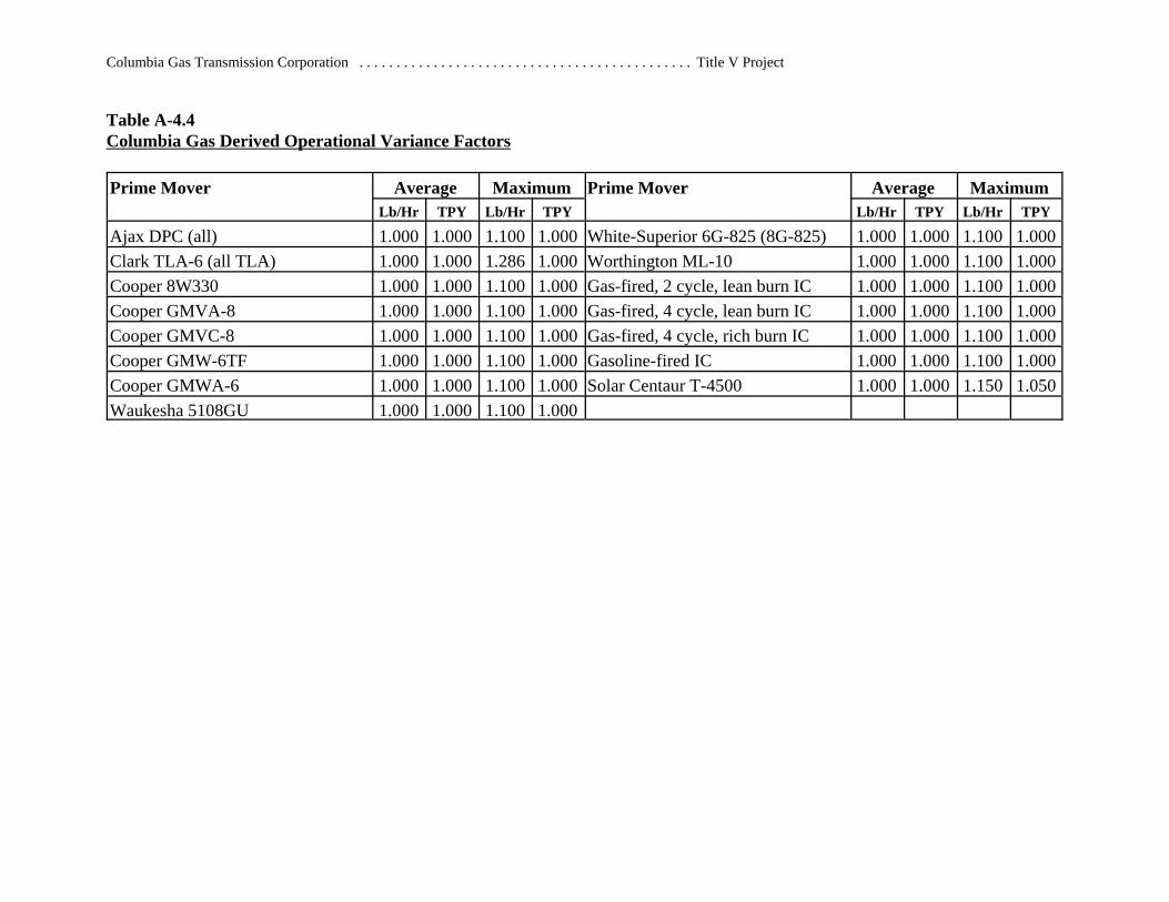
Table A-4.4Columbia Gas Derived Operational Variance Factors
Prime Mover Average Maximum Prime Mover Average MaximumLb/Hr TPY Lb/Hr TPY Lb/Hr TPY Lb/Hr TPY
Ajax DPC (all) 1.000 1.000 1.100 1.000 White-Superior 6G-825 (8G-825) 1.000 1.000 1.100 1.000Clark TLA-6 (all TLA) 1.000 1.000 1.286 1.000 Worthington ML-10 1.000 1.000 1.100 1.000Cooper 8W330 1.000 1.000 1.100 1.000 Gas-fired, 2 cycle, lean burn IC 1.000 1.000 1.100 1.000Cooper GMVA-8 1.000 1.000 1.100 1.000 Gas-fired, 4 cycle, lean burn IC 1.000 1.000 1.100 1.000Cooper GMVC-8 1.000 1.000 1.100 1.000 Gas-fired, 4 cycle, rich burn IC 1.000 1.000 1.100 1.000Cooper GMW-6TF 1.000 1.000 1.100 1.000 Gasoline-fired IC 1.000 1.000 1.100 1.000Cooper GMWA-6 1.000 1.000 1.100 1.000 Solar Centaur T-4500 1.000 1.000 1.150 1.050Waukesha 5108GU 1.000 1.000 1.100 1.000