Embed Size (px)
Citation preview
Pages
PW/WBG/467807D TABLE OF CONTENTS NOVEMBER 12, 2015 00 01 10 - 1
APPENDIX 8 STANDARD SPECIFICATION INDEX
03 30 00 Cast-In-Place Concrete ............................................................ 1- 7 31 10 00 Site Clearing............................................................................. 1- 2 31 23 16 Excavation................................................................................ 1- 3 31 23 19 Dewatering ............................................................................... 1- 1 31 23 23 Trench Backfill ........................................................................ 1- 8 32 12 16 Asphalt Paving ......................................................................... 1- 8 33 05 13 Manholes .................................................................................. 1- 15 40 27 00 Low Pressure Sewer System Force Main Piping-General ....... 1- 5 40 27 01 Ductile Iron Pipe and Fittings .................................................. 1- 1 40 27 02 High Density Polyethylene Pipe and Fittings (HDPE) ............ 1- 1 40 27 03 Polyvinyl Chloride Pipe and Fittings ....................................... 1- 1 40 27 04 AWWA C900 PVC Pipe and Fittings ...................................... 1- 1 40 27 05 SDR Pressure Rated Pipe ......................................................... 1- 1 40 27 20 Valves and Operators ............................................................... 1- 7 40 80 01 Piping Leakage Testing ............................................................ 1- 2 44 42 55A Barnes/Crane Packaged Low Pressure Pump Station .............. 1- 10 44 42 55B E-One Packaged Low Pressure Pump Station ......................... 1- 9
END OF SECTION

PW/WBG/467807D CAST-IN-PLACE CONCRETE NOVEMBER 11, 2015 03 30 00 - 1
SECTION 03 30 00 CAST-IN-PLACE CONCRETE
PART 1 GENERAL
1.01 SECTION INCLUDES
A. Concrete mix products including cementitious materials, aggregate, admixtures, mix design requirements, and concrete placing requirements.
1.02 REFERENCES
A. The following is a list of standards that may be referenced in this section:
1. Alabama Department of Transportation (ALDOT): a. Standard Specifications for Highway Construction
(Standard Specification). 2. American Concrete Institute (ACI):
a. 117, Specification for Tolerances for Concrete Construction and Materials.
b. 301, Specifications for Structural Concrete. c. 305.1, Specification for Hot Weather Concreting. d. 306.1, Standard Specification for Cold Weather Concreting.
3. ASTM International (ASTM): a. C31/C31M, Standard Practice for Making and Curing Concrete
Test Specimens in the Field. b. C33/C33M, Standard Specification for Concrete Aggregates. c. C39/C39M, Standard Test Method for Compressive Strength of
Cylindrical Concrete Specimens. d. C94/C94M, Standard Specification for Ready-Mixed Concrete. e. C143/C143M, Standard Test Method for Slump of Hydraulic-
Cement Concrete. f. C150/C150M, Standard Specification for Portland Cement. g. C231/C231M, Standard Test Method for Air Content of Freshly
Mixed Concrete by the Pressure Method. h. C260/C260M, Standard Specification for Air-Entraining
Admixtures for Concrete. 4. National Ready Mixed Concrete Association (NRMCA).
1.03 DEFINITIONS
A. Cold Weather: When ambient temperature is below 40 degrees F or is approaching 40 degrees F and falling.
CAST-IN-PLACE CONCRETE PW/WBG/467807D 03 30 00 - 2 NOVEMBER 11, 2015
B. Defective Area: Surface defects that include honeycomb, rock pockets, indentations, and surface voids greater than 3/16-inch deep, surface voids greater than 3/4 inch in diameter, cracks in liquid containment structures and below grade habitable spaces that are 0.005-inch wide and wider, and cracks in other structures that are 0.010-inch wide and wider, spalls, chips, embedded debris, sand streaks, mortar leakage from form joints, deviations in formed surface that exceed specified tolerances and include but are not limited to fins, form pop-outs, and other projections. At exposed concrete, defective areas also include texture irregularities, stains, and other color variations that cannot be removed by cleaning.
C. Exposed Concrete: Concrete surface that can be seen inside or outside of structure regardless of whether concrete is above water, dry at all times, or can be seen when structure is drained.
D. Hot Weather: As defined in ACI 305.1.
E. New Concrete: Less than 60 days old.
PART 2 PRODUCTS
2.01 GENERAL
A. Class A Concrete shall be formed, reinforced concrete having a 28 day minimum compressive strength of 4,000 psi.
1. Class A concrete shall be cast-in-place in forms for foundations, pipe collars, footings, piers, headwalls, manholes, junction boxes, and similar structures.
2. Mix design shall be “Concrete Class- Type A-1c” in accordance with Section 206 of the ALDOT, Standard Specifications.
B. Class B Concrete shall be non-formed, non-reinforced concrete having a 28-day minimum compressive strength of 3,000 psi.
1. Class B concrete shall be used for pipe protection, encasement, anchors, massive sections, and similar structures.
2. Mix design shall be “Concrete Class- Type A-1a” in accordance with Section 206 of the ALDOT, Standard Specifications.
C. Class C shall be non-formed non-reinforced cement mortar flowable fill having a 28 day minimum compressive strength of 1,000 psi.
1. Class C flowable fill shall be used for trench bottom stabilization, backfill around pipe and above pipe.
2. Mix design shall be “Mix 4” in accordance with Section 260 of the ALDOT, Standard Specifications.
PW/WBG/467807D CAST-IN-PLACE CONCRETE NOVEMBER 11, 2015 03 30 00 - 3
D. Other classes, types or design for cast-in-place concrete may be approved by the ESD as circumstances require.
2.02 MATERIALS
A. Cementitious Materials:
1. Cement: a. Portland Cement: Unless otherwise specified, conform to
requirements of ASTM C150/C150M. b. Furnish from one source.
2. When used for construction of manholes pump stations and locations where in contact with wastewater, the Tri Calcium Aluminate content must be less than 5.5 percent.
B. Aggregates: Furnish from one source for each aggregate type used in a mix design.
1. Normal-Weight Aggregates: a. In accordance with ASTM C33/C33M, except as modified herein.
2. Fine Aggregates: a. Natural sand consisting of clean, hard, durable, uncoated grains. b. ASTM C33/C33M.
3. Coarse Aggregate: a. Uncoated particles of sound, durable rock of uniform quality,
without any excess of flat, elongated or laminated pieces. b. No surface, yellow or soft stone shall be permitted. c. Specific gravity of the stone shall be not less than 2.55.
C. Water: Mixing water for concrete shall be potable water.
2.03 ANCILLARY MATERIALS
A. Reinforcing Material for Cast-In-Place Concrete:
1. Reinforcing bars shall conform to the requirements of ASTM A614. 2. Reinforcing bars shall be grade 60 deformed bars, or as specified by
Design Engineer. 3. Welded wire fabric or cold-drawn wire for concrete reinforcement shall
conform to the requirements of ASTM A185 or ASTM A82, respectively.
B. Grout: Grout shall consist of mixture of water and cement or water and one-part cement to two parts mortar sand, by volume. The water may be adjusted to produce a mixture suitable for field conditions.
C. Water Stop Grout/Hydraulic Cement: Shall be Bonsal Instant Hydraulic Cement, or BASF MasterSeal 590. No other products will be allowed.
CAST-IN-PLACE CONCRETE PW/WBG/467807D 03 30 00 - 4 NOVEMBER 11, 2015
2.04 CONCRETE MIXING
A. General: In accordance with ACI 301, except as modified herein.
B. Truck Mixers:
1. For every truck, test slump of samples taken per ASTM C94/C94M, paragraph 12.5.1.
2. Where specified slump is more than 4 inches, and if slump tests differ by more than 2 inches, discontinue use of truck mixer, unless causing condition is corrected and satisfactory performance is verified by additional slump tests.
PART 3 EXECUTION
3.01 PLACING CONCRETE
A. Preparation: Meet requirements ACI 301, except as modified herein.
B. Placement into Formwork:
1. Reinforcement: Secure in position before placing concrete. 2. Place concrete as soon as possible after leaving mixer, without
segregation or loss of ingredients, without splashing forms or steel above, and in layers not over 1.5 feet deep, except for slabs which shall be placed full depth. Place and consolidate successive layers prior to initial set of first layer to prevent cold joints.
3. Use placement devices, for example chutes, pouring spouts, and pumps as required to prevent segregation.
4. Vertical Free Fall Drop to Final Placement: a. Forms 8 Inches or Less Wide: 5 feet. b. Forms Wider than 8 Inches: 8 feet, except as specified.
5. For placements where drops are greater than specified, use placement device such that free fall below placement device conforms to required value. a. Limit free fall to prevent segregation caused by aggregates hitting
steel reinforcement. 6. Do not use aluminum conveying devices. 7. Provide sufficient illumination in the interior of forms so concrete
deposition is visible, permitting confirmation of consolidation quality. 8. Joints in Footings and Slabs:
a. Ensure space beneath plastic waterstop completely fills with concrete.
b. During concrete placement, make visual inspection of entire waterstop area.
PW/WBG/467807D CAST-IN-PLACE CONCRETE NOVEMBER 11, 2015 03 30 00 - 5
c. Limit concrete placement to elevation of waterstop in first pass, vibrate concrete under waterstop, lift waterstop to confirm full consolidation without voids, and place remaining concrete to full height of slab.
d. Apply procedure to full length of waterstop. 9. Trowel and round off top exposed edges of walls with 1/4-inch radius
steel edging tool. 10. Cure concrete in accordance with ACI 308.
C. Conveyor Belts and Chutes:
1. Design and arrange ends of chutes, hopper gates, and other points of concrete discharge throughout conveying, hoisting, and placing system for concrete to pass without becoming segregated.
2. Do not use chutes longer than 50 feet. 3. Minimum Slopes of Chutes: Angled to allow concrete to readily flow
without segregation. 4. Conveyor Belts:
a. Wipe clean with device that does not allow mortar to adhere to belt.
b. Cover conveyor belts and chutes.
D. Retempering: Not permitted for concrete where cement has partially hydrated.
E. Pumping of Concrete:
1. Provide standby pump, conveyor system, crane and concrete bucket, or other system onsite during pumping, for adequate redundancy to ensure completion of concrete placement without cold joints in case of primary placing equipment breakdown.
2. Minimum Pump Hose (Conduit) Diameter: 4 inches. 3. Replace pumping equipment and hoses (conduits) that are not
functioning properly.
F. Maximum Size of Concrete Placements: Limit size of each placement to allow for strength gain and volume change as a result of shrinkage.
G. Hot Weather:
1. Prepare ingredients, mix, place, cure, and protect in accordance with ACI 301, ACI 305.1, and as follows: a. Maintain concrete temperature below 90 degrees F at time of
placement, or furnish test data or other proof that admixtures and mix ingredients do not produce flash set plastic shrinkage, or cracking as a result of heat of hydration. Cool ingredients before mixing to maintain fresh concrete temperatures as specified or less.
CAST-IN-PLACE CONCRETE PW/WBG/467807D 03 30 00 - 6 NOVEMBER 11, 2015
b. Provide for windbreaks, shading, fog spraying, sprinkling, ice, wet cover, or other means as necessary to maintain concrete at or below specified temperature.
H. Cold Weather Placement:
1. Unless otherwise permitted, shall be in accordance with requirements of ACI 306.1 and as follows: a. Cold weather requirements shall apply when ambient temperature
is below 40 degrees F or approaching 40 degrees F and falling. b. Do not place concrete over frozen earth or against surfaces with
frost or ice present. Frozen earth shall be thawed to acceptance of Engineer.
c. Unless otherwise permitted, do not place concrete in contact with surfaces less than 35 degrees F; requirement is applicable to all surfaces including reinforcement and other embedded items.
d. Provide supplemental external heat as needed when other means of thermal protection are unable to maintain minimum surface temperature of concrete as specified in ACI 306.1.
e. Maintain minimum surface temperature of concrete as specified in ACI 306.1 for no less than 3 days during cold weather conditions.
3.02 TESTING
A. Strength Tests During the Work:
1. If concrete is being poured, the Contractor will make four concrete test cylinders for each 50 cubic yards poured or for each days pour, whichever amount of concrete is smaller.
2. Cylinders will be made and tested in accordance with ASTM C31, ASTM C172 and ASTM C39.
3. The standard age of the test shall be 28 days with the first cylinder broken at 7 days.
4. If the 7-day break exceeds the specified strength, then no further tests will be made until the 28th day.
5. If the 7-day break does not meet the specified strength, then the second cylinder will be tested at the 14th day.
6. In either event, the remaining cylinder(s) will be tested at the 28th day. 7. When the test cylinders fail to conform to the compressive strength
requirements, the ESD shall have the right to order a change in the concrete mix for the remaining portions of the work. The Contractor may wish to make additional cylinders at his own expense as verification.
PW/WBG/467807D CAST-IN-PLACE CONCRETE NOVEMBER 11, 2015 03 30 00 - 7
B. Test of Hardened Concrete In, or Removed From the Structure:
1. When the results of the strength tests of the control specimens indicate the concrete as placed does not meet specification requirements or where there is other evidence that the quality of the concrete is below specification requirements, core-boring tests shall be made in conformance with ASTM C42.
2. Core specimens will be tested by a certified testing laboratory approved by the ESD.
3. All deficiencies shall be corrected, or, if the Contractor elects, he may submit a proposal, for approval, that load tests be made.
4. If the proposal is approved, the load test shall be made by the Contractor and the test results evaluated by the ESD.
5. If any concrete shows evidence of failure during the load test, or fails the core test as evaluated, the deficiency shall be corrected. Any deficiency shall be corrected in a manner approved by the ESD.
END OF SECTION

PW/WBG/467807D SITE CLEARING NOVEMBER 11, 2015 31 10 00 - 1
SECTION 31 10 00 SITE CLEARING
PART 1 GENERAL
1.01 DEFINITIONS
A. Interfering or Objectionable Material: Trash, rubbish, and junk; vegetation and other organic matter, whether alive, dead, or decaying; topsoil.
B. Clearing: Removal of interfering or objectionable material lying on or protruding above ground surface.
C. Grubbing: Removal of vegetation and other organic matter including stumps, buried logs, and roots greater than 2-inch caliper to a depth of 6 inches below subgrade.
D. Scalping: Removal of sod without removing more than upper 3 inches of topsoil.
E. Stripping: Removal of topsoil remaining after applicable scalping is completed.
F. Project Limits: Areas, as shown or specified, within which Work is to be performed.
PART 2 PRODUCTS (NOT USED)
PART 3 EXECUTION
3.01 GENERAL
A. Clear, grub, and strip areas actually needed for waste disposal, borrow, or Site improvements within limits shown or specified.
B. Do not injure or deface vegetation that is not designated for removal.
3.02 CLEARING
A. Clear areas within limits shown on the Design Drawings.
B. Fell trees so that they fall away from facilities and vegetation not designated for removal.
C. Cut off shrubs, brush, weeds, and grasses to within 2 inches of ground surface.
SITE CLEARING PW/WBG/467807D 31 10 00 - 2 NOVEMBER 11, 2015
3.03 GRUBBING
A. Grub areas within limits shown on the Design Drawings.
3.04 SCALPING
A. Do not remove sod until after clearing and grubbing is completed and resulting debris is removed.
B. Scalp areas within limits shown on the Design Drawings.
3.05 STRIPPING
A. Do not remove topsoil until after scalping is completed.
B. Strip areas within limits to minimum depths shown on the Design Drawings. Do not remove subsoil with topsoil.
3.06 DISPOSAL
A. Clearing and Grubbing Debris: Dispose of debris offsite.
B. Scalpings: As specified for clearing and grubbing debris.
C. Strippings:
1. Dispose of strippings that are unsuitable for topsoil or that exceed quantity required for topsoil offsite.
2. Stockpile topsoil in sufficient quantity to meet Project needs. Dispose of excess strippings as specified for clearing and grubbing.
END OF SECTION
PW/WBG/467807D EXCAVATION NOVEMBER 11, 2015 31 23 16 - 1
SECTION 31 23 16 EXCAVATION
PART 1 GENERAL
1.01 QUALITY ASSURANCE
A. Provide adequate survey control to avoid unauthorized over excavation.
1.02 WEATHER LIMITATIONS
A. Material excavated when frozen or when air temperature is less than 32 degrees F shall not be used as fill or backfill until material completely thaws.
B. Material excavated during inclement weather shall not be used as fill or backfill until after material drains and dries sufficiently for proper compaction.
1.03 SEQUENCING AND SCHEDULING
A. Clearing, Grubbing, and Stripping: Complete applicable Work prior to excavating.
B. Dewatering: Conform to applicable requirements of Section 31 23 19, Dewatering, prior to initiating excavation.
C. Excavation Support: Install and maintain, in accordance with the requirements of OSHA, local and state regulations to ensure the safety of workers, support sides of excavations and prevent detrimental settlement and lateral movement of existing facilities, adjacent property, and completed Work.
PART 2 PRODUCTS (NOT USED)
PART 3 EXECUTION
3.01 GENERAL
A. Excavate to lines, grades, and dimensions shown and as necessary to accomplish Work and allow placement of the base material for the main, manhole or structure to be placed on undisturbed soil. Excavate to within tolerance of plus or minus 0.1 foot, except where dimensions or grades are shown or specified as maximum or minimum. Allow for forms, working space, granular base, topsoil, and similar items, wherever applicable. Trim to neat lines where concrete is to be placed.
EXCAVATION PW/WBG/467807D 31 23 16 - 2 NOVEMBER 11, 2015
B. Do not over excavate without written authorization of Engineer. In the event of over excavation backfill with Granular Backfill in accordance with Section 31 23 23, Trench Backfill.
C. Where constructing within fill or in areas where the soil is organic and/or has a low bearing capacity the services of a geotechnical engineer shall be employed to ensure that the material has been properly placed and compacted to support the main, manhole or other structure and prevent settlement/deflection. Use of geotextile and/or flowable fill/controlled low strength material may be required to provide appropriate support.
3.02 UNCLASSIFIED EXCAVATION
A. Excavation is unclassified. Complete all excavation regardless of the type, nature, or condition of the materials encountered.
3.03 TRENCH WIDTH
A. Minimum Width of Trenches:
1. 18 inches greater than outside diameter or width of the pipe. 2. Increase trench widths by thicknesses of sheeting/excavation support
system where system is required.
B. Maximum Trench Width: Unlimited, unless otherwise shown or specified, or unless excess width will cause damage to existing facilities, adjacent property, or completed Work.
3.04 EMBANKMENT AND CUT SLOPES
A. Shape, trim, and finish cut slopes to conform with lines, grades, and cross-sections shown, with proper allowance for topsoil or slope protection, where shown.
B. Remove stones and rock that exceed 3-inch diameter and that are loose and may roll down slope. Remove exposed roots from cut slopes.
C. Round tops of cut slopes in soil to not less than a 6-foot radius, provided such rounding does not extend offsite or outside easements and rights-of-way, or adversely impacts existing facilities, adjacent property, or completed Work.
3.05 STOCKPILING EXCAVATED MATERIAL
A. Stockpile excavated material that is suitable for use as fill or backfill until material is needed.
B. Confine stockpiles to within easements, rights-of-way, and approved work areas. Do not obstruct roads or streets.
PW/WBG/467807D EXCAVATION NOVEMBER 11, 2015 31 23 16 - 3
C. Do not stockpile excavated material adjacent to trenches and other excavations, unless excavation side slopes and excavation support systems are designed, constructed, and maintained for stockpile loads.
D. Do not stockpile excavated materials near or over existing facilities, adjacent property, or completed Work, if weight of stockpiled material could induce excessive settlement.
3.06 DISPOSAL OF SPOIL
A. Dispose of excavated materials, which are unsuitable or exceed quantity needed for fill or backfill, offsite.
END OF SECTION

PW/WBG/467807D DEWATERING NOVEMBER 11, 2015 31 23 19 - 1
SECTION 31 23 19 DEWATERING
PART 1 GENERAL
1.01 SECTION INCLUDES:
A. Dewatering of excavations and other work sites including trench, and tunnel excavations.
PART 2 PRODUCTS (NOT USED)
PART 3 EXECUTION
3.01 GENERAL
A. Continuously control water during course of construction, including weekends and holidays and during periods of work stoppages, and provide adequate backup systems to maintain control of water.
3.02 SURFACE WATER CONTROL
A. Remove surface runoff controls when no longer needed.
3.03 DEWATERING SYSTEMS
A. Permit, provide, operate, and maintain dewatering systems of sufficient size and capacity to permit excavation and subsequent construction in dry and to lower and maintain groundwater level a minimum of 2 feet below the lowest point of excavation. Continuously maintain excavations free of water, regardless of source, and until backfilled to final grade.
B. Provide sufficient redundancy in each system to keep excavation free of water in event of component failure.
C. Provide supplemental ditches and sumps only as necessary to collect water from local seeps. Do not use ditches and sumps as primary means of dewatering.
END OF SECTION

PW/WBG/467807D TRENCH BACKFILL NOVEMBER 11, 2015 31 23 23- 1
SECTION 31 23 23 TRENCH BACKFILL
PART 1 GENERAL
1.01 SUMMARY
A. Where required, modify the backfill requirement to meet local / state requirements.
1.02 REFERENCES
A. The following is a list of standards which may be referenced in this section:
1. American Public Works Association (APWA): Uniform Color Code. 2. ASTM International (ASTM):
a. C33/C33M, Standard Specification for Concrete Aggregates. b. C94/C94M, Standard Specification for Ready-Mixed Concrete. c. C117, Standard Test Method for Materials Finer than
75 Micrometer (No. 200) Sieve in Mineral Aggregates by Washing.
d. C136, Standard Test Method for Sieve Analysis of Fine and Coarse Aggregates.
e. C150/C150M, Standard Specification for Portland Cement. f. C618, Standard Specification for Coal Fly Ash and Raw or
Calcined Natural Pozzolan for Use in Concrete. g. C1012/C1012M, Standard Test Method for Length Change of
Hydraulic-Cement Mortars Exposed to a Sulfate Solution. h. D698, Standard Test Methods for Laboratory Compaction
Characteristics of Soil Using Standard Effort (12,400 ft-lbf/ft3 (600 kN-m/m3)).
i. D1140, Standard Test Methods for Amount of Material in Soils Finer than No. 200 (75 micrometer) Sieve.
j. D1557, Standard Test Methods for Laboratory Compaction Characteristics of Soil using Modified Effort (56,000 ft-lbf/ft3 (2,700 kN-m/m3)).
k. D2487, Standard Practice for Classification of Soils for Engineering Purposes (Unified Soil Classification System).
l. D4253, Standard Test Methods for Maximum Index Density and Unit Weight of Soils Using a Vibratory Table.
m. D4254, Standard Test Methods for Minimum Index Density and Unit Weight of Soils and Calculation of Relative Density.
n. D4318, Standard Test Methods for Liquid Limit, Plastic Limit, and Plasticity Index of Soils.
o. D4832, Standard Test Method for Preparation and Testing of Controlled Low Strength Material (CLSM) Test Cylinders.
TRENCH BACKFILL PW/WBG/467807D 31 23 23 - 2 NOVEMBER 11, 2015
3. National Electrical Manufacturers Association (NEMA): Z535.1, Safety Colors.
1.03 DEFINITIONS
A. Base Rock: Granular material upon which manhole bases and other structures are placed.
B. Bedding Material: Granular material upon which pipes, conduits, cables, or duct banks are placed.
C. Imported Material: Material obtained by Contractor from source(s) offsite.
D. Lift: Loose (uncompacted) layer of material.
E. Pipe Zone: Backfill zone that includes full trench width and extends from prepared trench bottom to an upper limit above top outside surface of pipe, conduit, cable or duct bank.
F. Prepared Trench Bottom: Graded trench bottom after excavation and installation of stabilization material, if required, but before installation of bedding material.
G. Relative Compaction: The ratio, in percent, of the as-compacted field dry density to the laboratory maximum dry density as determined by ASTM D698. Corrections for oversize material may be applied to either as-compacted field dry density or maximum dry density, as determined by Engineer.
H. Relative Density: As defined by ASTM D4253 and ASTM D4254.
I. Selected Backfill Material: Material available onsite that the Owner/Owner’s Representative determines to be suitable for a specific use.
J. Well-Graded: A mixture of particle sizes that has no specific concentration or lack thereof of one or more sizes producing a material type that, when compacted, produces a strong and relatively incompressible soil mass free from detrimental voids. Satisfying both of the following requirements, as defined in ASTM D2487:
1. Coefficient of Curvature: Greater than or equal to 1 and less than or equal to 3.
2. Coefficient of Uniformity: Greater than or equal to 4 for materials classified as gravel, and greater than or equal to 6 for materials classified as sand.
PW/WBG/467807D TRENCH BACKFILL NOVEMBER 11, 2015 31 23 23- 3
PART 2 PRODUCTS
2.01 MARKING TAPE
A. Detectable:
1. Solid aluminum foil, visible on unprinted side, encased in protective high visibility, inert polyethylene plastic jacket.
2. Foil Thickness: Minimum 0.35 mils. 3. Laminate Thickness: Minimum 5 mils. 4. Width: 3 inches. 5. Identifying Lettering: Minimum 1-inch high, permanent black lettering
imprinted continuously over entire length. 6. Joining Clips: Tin or nickel-coated furnished by tape manufacturer. 7. Manufacturers and Products:
a. Reef Industries; Terra Tape, Sentry Line Detectable. b. Mutual Industries; Detectable Tape. c. Presco; Detectable Tape.
B. Color: Green in accordance with APWI Uniform Color Code.
2.02 TRENCH STABILIZATION MATERIAL
A. Base Rock: Number 1 in accordance with the Course Aggregate Gradation Table, ALDOT Standard Specifications.
B. Granular Backfill: Number 57 or 67 in accordance with the Course Aggregate Gradation Table, ALDOT Standard Specifications.
2.03 BEDDING MATERIAL AND PIPE ZONE MATERIAL
A. Number 57 or 67 in accordance with the Course Aggregate Gradation Table, ALDOT Standard Specifications.
2.04 CLASS C - EARTH BACKFILL
A. Soil, loam, or other excavated material suitable for use as backfill.
B. Free from roots or organic matter, refuse, boulders and material larger than 1/2 cubic foot, or other deleterious materials.
2.05 CLASS A - PROCESSED EARTH BACKFILL
A. Class C Earth backfill, meeting the following additional requirement.
1. Free of boulders and cobbles that would be retained on a 6-inch screen 3-inch sieve.
TRENCH BACKFILL PW/WBG/467807D 31 23 23 - 4 NOVEMBER 11, 2015
2.06 FLOWABLE FILL
A. Class C Concrete as specified in Section 03 30 00, Cast-in-Place Concrete.
2.07 CONCRETE BACKFILL
A. Class C Concrete as specified in Section 03 30 00, Cast-in-Place Concrete.
2.08 GRAVEL SURFACING ROCK
A. Number 67 in accordance with the Course Aggregate Gradation Table, ALDOT Standard Specifications.
2.09 TOPSOIL
A. Natural, friable, sandy loam, obtained from well-drained areas, free from objects larger than 1-1/2 inches maximum dimension, and free of subsoil, roots, grass, other foreign matter, hazardous or toxic substances, and deleterious material that may be harmful to plant growth or may hinder grading, planting, or maintenance.
B. Composition: In general accordance with ASTM D5268:
1. Gravel-Sized Fraction: Maximum 5 percent by weight retained on a No. 10 sieve.
2. Sand-Sized Fraction: Minimum 20 to 60 percent passing No. 10 sieve. 3. Silt and Clay-Sized Fraction: Minimum 35 to 70 percent.
C. Organic Matter: Minimum 1.5 percent by dry weight as determined in accordance with ASTM D2974.
D. pH: Range 5.0 to 7.0.
E. Textural Amendments: Amend as necessary to conform to required composition by incorporating sand, peat, manure, or sawdust.
PART 3 EXECUTION
3.01 TRENCH PREPARATION
A. Water Control:
1. As specified in Section 31 23 19, Dewatering. 2. Remove water in a manner that minimizes soil erosion from trench sides
and bottom. 3. Provide continuous water control until trench backfill is complete.
PW/WBG/467807D TRENCH BACKFILL NOVEMBER 11, 2015 31 23 23- 5
B. Remove foreign material and backfill contaminated with foreign material that falls into trench.
3.02 TRENCH BOTTOM
A. Firm Subgrade: Grade with hand tools, remove loose and disturbed material, and trim off high areas and ridges left by excavating bucket teeth. Allow space for bedding material if shown or specified.
B. Soft Subgrade: If subgrade is encountered that may require removal to prevent pipe settlement, notify Owner/Owner’s Representative. Owner/Owner’s Representative will determine depth of overexcavation, if any required.
3.03 TRENCH STABILIZATION MATERIAL INSTALLATION
A. Rebuild trench bottom with trench stabilization material.
B. Place material over full width of trench in 6-inch lifts to required grade, providing allowance for bedding thickness.
C. Compact each lift so as to provide a firm, unyielding support for the bedding material prior to placing succeeding lifts.
3.04 BEDDING
A. Furnish imported bedding material where, in the opinion of Owner/Owner’s Representative, excavated material is unsuitable for bedding or insufficient in quantity.
B. Place over full width of prepared trench bottom in two equal lifts when required depth exceeds 8 inches.
C. Hand grade and compact each lift to provide a firm, unyielding surface.
D. Minimum Thickness: As follows, except increase depths listed by 2 inches in areas of rock excavation:
1. Pipe 18 Inches and Smaller: 4 inches.
E. Check grade and correct irregularities in bedding material. Loosen top 1 inch to 2 inches of compacted bedding material with a rake or by other means to provide a cushion before laying each section of pipe, conduit, direct-buried cable, or duct bank.
F. Install to form continuous and uniform support except at bell holes, if applicable, or minor disturbances resulting from removal of lifting tackle.
TRENCH BACKFILL PW/WBG/467807D 31 23 23 - 6 NOVEMBER 11, 2015
G. Bell or Coupling Holes: Excavate in bedding at each joint to permit proper assembly and inspection of joint and to provide uniform bearing along barrel of pipe or conduit.
3.05 BACKFILL PIPE ZONE
A. Upper limit of pipe zone shall not be less than 12 inches:
B. Restrain pipe as necessary to prevent their movement during backfill operations.
C. Place material simultaneously in lifts on both sides of pipe and, if applicable, between pipes, conduit, cables, and duct banks installed in same trench.
1. Pipe 10-Inch and Smaller Diameter: First lift less than or equal to 1/2 pipe diameter.
2. Pipe Over 10-Inch Diameter: Maximum 6-inch lifts.
D. Thoroughly tamp each lift, including area under haunches, with handheld tamping bars supplemented by “walking in” and slicing material under haunches with a shovel to ensure voids are completely filled before placing each succeeding lift.
E. Each lift shall be compacted with a minimum of two passes by either a vibratory plate compactor. Take care to avoid damaging pipe and pipe coating.
3.06 MARKING TAPE INSTALLATION
A. Continuously install detectable marking tape along centerline of buried piping, on top of last lift of pipe zone material.
1. Detectable Marking Tape: Install with nonmetallic piping and waterlines.
3.07 BACKFILL ABOVE PIPE ZONE
A. General:
1. Process excavated material to meet specified gradation requirements. 2. Adjust moisture content as necessary to obtain specified compaction. 3. Do not allow backfill to free fall into trench or allow heavy, sharp
pieces of material to be placed as backfill until after at least 2 feet of backfill has been provided over top of pipe.
4. Do not use power driven impact type compactors for compaction until at least 4 feet of backfill is placed over top of pipe.
PW/WBG/467807D TRENCH BACKFILL NOVEMBER 11, 2015 31 23 23- 7
5. Backfill to grade with proper allowances for topsoil, crushed rock surfacing, and pavement thicknesses, wherever applicable.
6. Backfill around structures with same class backfill as specified for adjacent trench, unless otherwise shown or specified.
B. Class A Processed Earth Backfill:
1. Place in lifts not exceeding thickness of 9 inches. 2. Mechanically compact each lift to a minimum of 95 percent relative
compaction prior to placing succeeding lifts.
C. Class C Earth Backfill:
1. Backfill with earth backfill. 2. Leave trench with backfill material neatly mounded across the
entire trench width, but not more than 6 inches above the adjacent ground surface.
3. In lawn, garden, or similar type areas, maintain trench level with the existing adjacent grade.
4. At Other Locations: a. Estimate and provide amount of backfill material required so that
after normal settlement, settled surface will match adjacent ground surface.
b. Neatly windrow material over trench, and remove excess. c. Correct excess or deficiency of backfill material apparent after
settlement and within correction period by regrading, and disposing of excess material or adding additional material where deficient.
D. Class D Backfill: Backfill trench above pipe zone with granular backfill in lifts not exceeding 8 inches. Compact each lift to a minimum of 95 percent relative compaction prior to placing succeeding lifts.
E. Concrete Backfill:
1. Place above bedding. 2. Minimum Concrete Thickness: 6 inches on top and sides of pipe. 3. Do not allow dirt or foreign material to become mixed with concrete
during placement. 4. Allow sufficient time for concrete to reach initial set before additional
backfill material is placed in trench. 5. Prevent flotation of pipe. 6. Begin and end concrete backfill within 4 inches of a pipe joint on each
end. 7. Do not encase pipe joints except within the limits of the concrete
backfill.
TRENCH BACKFILL PW/WBG/467807D 31 23 23 - 8 NOVEMBER 11, 2015
F. Controlled Low Strength Material:
1. Discharge from truck mounted drum type mixer into trench. 2. Place in lifts as necessary to prevent uplift (flotation) of new and
existing facilities. 3. In traveled areas fill entire trench section to pavement finish grade for a
temporary driving surface, and screed off excess and finish with a float. 4. In other areas fill trench section as shown.
3.08 REPLACEMENT OF TOPSOIL
A. Replace topsoil in top 12 inches of backfilled trench.
B. Maintain finished grade of topsoil even with adjacent area and grade as necessary to restore drainage.
3.09 MAINTENANCE OF TRENCH BACKFILL
A. After each section of trench is backfilled, maintain surface of backfilled trench even with adjacent ground surface until final surface restoration is completed.
B. Gravel Surfacing Rock: Add gravel surfacing rock where applicable and as necessary to keep surface of backfilled trench even with adjacent ground surface, and grade and compact as necessary to keep surface of backfilled trenches smooth, free from ruts and potholes, and suitable for normal traffic flow.
C. Topsoil: Add topsoil where applicable and as necessary to maintain surface of backfilled trench level with adjacent ground surface.
D. Other Areas: Add excavated material where applicable and keep surface of backfilled trench level with adjacent ground surface.
3.10 SETTLEMENT OF BACKFILL
A. Settlement of trench backfill, or of fill, or facilities constructed over trench backfill will be considered a result of defective compaction of trench backfill.
END OF SECTION
PW\WBG\430292D ASPHALT PAVING NOVEMBER 11, 2015 32 12 16 - 1
SECTION 32 12 16 ASPHALT PAVING
PART 1 GENERAL
1.01 REQUIREMENTS
A. Pave width shown on the Drawings and as required for restoration damaged during completion of the Work detailed.
1.02 DEFINITIONS
A. Combined Aggregate: All mineral constituents of asphalt concrete mix, including mineral filler and separately sized aggregates.
B. RAP: Reclaimed asphalt pavement.
C. Standard Specifications: Alabama Department of Transportation Standard Specifications for Highway Construction, 2006 Edition.
1.03 DESIGN REQUIREMENTS
A. Prepare asphalt concrete mix design, meeting the following design criteria, tolerances, and other requirements of Section 410, of the Standard Specifications, Hot Mix Asphalt Pavement.
1.04 SUBMITTALS
A. Informational Submittals:
1. Asphalt Concrete Mix Formula: a. Submit minimum of 15 days prior to start of production. b. Submittal to include the following information:
1) Gradation and portion for each aggregate constituent used in mixture to produce a single gradation of aggregate within specified limits.
2) Bulk specific gravity for each aggregate constituent. 3) Measured maximum specific gravity of mix at optimum
asphalt content determined in accordance with ASTM D2041.
4) Properties as stated in Section 410 of the Standard Specifications, for at least four different asphalt contents other than optimum, two below optimum, and two above optimum.
5) Percent of asphalt lost due to absorption by aggregate.
ASPHALT PAVING PW\WBG\430292D 32 12 16 - 2 NOVEMBER 11, 2015
6) Index of Retained Strength (TSR) at optimum asphalt content as determined by AASHTO T283.
7) Percentage of asphalt cement, to nearest 0.1 percent, to be added to mixture.
8) Optimum mixing temperature. 9) Optimum compaction temperature. 10) Temperature-viscosity curve of asphalt cement to be used. 11) Brand name of any additive to be used and percentage
added to mixture. 2. Test Report for Asphalt Cement:
a. Submit minimum 10 days prior to start of production. b. Show appropriate test method(s) for each material and the test
results. 3. Manufacturer’s Certificate of Compliance, in accordance with
Section 01 43 33, Manufacturers’ Field Services, for the following materials: a. Aggregate: Gradation, source test results as defined in
Section 410 of the Standard Specifications. b. Asphalt for Binder: Type, grade, and viscosity-temperature curve. c. Prime Coat: Type and grade of asphalt. d. Tack Coat: Type and grade of asphalt. e. Additives. f. Mix: Conforms to job-mix formula.
4. Statement of qualification for independent testing laboratory. 5. Test Results:
a. Mix design. b. Asphalt concrete core. c. Gradation and asphalt content of uncompacted mix. d. Field density. e. Quality control.
1.05 QUALITY ASSURANCE
A. Qualifications:
1. Independent Testing Laboratory: In accordance with ASTM E329. 2. Asphalt concrete mix formula shall be prepared by approved certified
independent laboratory under the supervision of a certified asphalt technician.
1.06 ENVIRONMENTAL REQUIREMENTS
A. Temperature: Do not apply asphalt materials or place asphalt mixes when ground temperature is lower than 10 degrees C (50 degrees F) or air temperature is lower than 4 degrees C (40 degrees F). Measure ground and air temperature in shaded areas away from heat sources or wet surfaces.
PW\WBG\430292D ASPHALT PAVING NOVEMBER 11, 2015 32 12 16 - 3
B. Moisture: Do not apply asphalt materials or place asphalt mixes when application surface is wet.
PART 2 PRODUCTS
2.01 MATERIALS
A. Tack Coat: Emulsified asphalt, conform to Section 405 of the Standard Specifications.
B. Sand (Blotter Material): Clean, dry, with 100 percent passing 4.75-millimeter (No. 4) sieve, and a maximum of 10 percent passing 75 (m (No. 200) sieve.
2.02 ASPHALT CONCRETE MIX
A. General:
1. Mix formula shall not be modified except with written approval of Engineer.
2. Source Changes: a. Should material source(s) change, establish new asphalt concrete
mix formula before new material(s) is used. b. Perform check tests of properties of plant-mix bituminous
materials on first day of production and as requested by Engineer to confirm that properties are in compliance with design criteria.
c. Make adjustments in gradation or asphalt content as necessary to meet design criteria.
B. Asphalt Concrete: As specified in Section 410 of the Standard Specifications.
C. Composition: Hot-plant mix of aggregate, mineral filler if required, and paving grade asphalt cement. The several aggregate fractions shall be sized, uniformly graded, and combined in such proportions that resulting mixture meets grading requirements of mix formula.
D. Aggregate: General: As specified in Section 410 of the Standard Specifications.
E. Mineral Filler: In accordance with Section 410 of the Standard Specifications.
F. Asphalt Cement: Paving Grade as specified in Section 410 of the Standard Specifications.
ASPHALT PAVING PW\WBG\430292D 32 12 16 - 4 NOVEMBER 11, 2015
PART 3 EXECUTION
3.01 GENERAL
A. Traffic Control:
1. In accordance with Section 01 50 00, Temporary Facilities and Controls.
2. Minimize inconvenience to traffic, but keep vehicles off freshly treated or paved surfaces to avoid pickup and tracking of asphalt.
B. Driveways: Repave driveways from which pavement was removed. Leave driveways in as good or better condition than before start of construction.
3.02 LINE AND GRADE
A. Provide and maintain intermediate control of line and grade, independent of underlying base, to meet finish surface grades and minimum thickness.
B. Shoulders: Construct to line, grade, and cross-section shown.
3.03 APPLICATION EQUIPMENT
A. In accordance with Section 410 of the Standard Specifications.
3.04 PREPARATION
A. Prepare subgrade as specified in Section 31 23 13, Subgrade Preparation.
B. Existing Roadway:
1. Modify profile by grinding, milling, or overlay methods as approved, to provide meet lines and surfaces and to produce smooth riding connection to existing facility.
2. Remove existing material to a minimum depth of 1-inch. 3. Paint edges of meet line with tack coat prior to placing new pavement.
C. Thoroughly coat edges of contact surfaces (curbs, manhole frames) with emulsified asphalt or asphalt cement prior to laying new pavement. Prevent staining of adjacent surfaces.
3.05 PAVEMENT APPLICATION
A. General: Place asphalt concrete mixture on approved, prepared base in conformance with Section 410 of the Standard Specifications.
PW\WBG\430292D ASPHALT PAVING NOVEMBER 11, 2015 32 12 16 - 5
B. Tack Coat:
1. Prepare material, as specified in Section 410 of the Standard Specifications, prior to application.
2. Apply uniformly to clean, dry surfaces avoiding overlapping of applications.
3. Do not apply more tack coat than necessary for the day’s paving operation.
4. Touch up missed or lightly coated surfaces and remove excess material. 5. Application Rate: Minimum 0.05 to 0.15 gallon per square yard of
surface area.
C. Pavement Mix:
1. Prior to Paving: a. Sweep primed surface free of dirt, dust, or other foreign matter. b. Patch holes in primed surface with asphalt concrete pavement
mix. c. Blot excess prime material with sand.
2. Place asphalt concrete pavement mix in two equal lifts. 3. Compacted Lift Thickness:
a. Minimum: Twice maximum aggregate size, but in no case less than 1 inch.
b. Maximum: 4 inches. 4. Total Compacted Thickness: As shown. 5. Apply such that meet lines are straight and edges are vertical. 6. Collect and dispose of segregated aggregate from raking process. Do not
scatter material over finished surface. 7. Joints:
a. Offset edge of each layer a minimum of 6 inches so joints are not directly over those in underlying layer.
b. Offset longitudinal joints in roadway pavements so longitudinal joints in wearing layer coincide with pavement centerlines and lane divider lines.
c. Form transverse joints by cutting back on previous day’s run to expose full vertical depth of layer.
8. Succeeding Lifts: Apply tack coat to pavement surface between each lift.
9. After placement of pavement, seal meet line by painting a minimum of 6 inches on each side of joint with cut-back or emulsified asphalt. Cover immediately with sand.
D. Compaction: Roll until roller marks are eliminated and minimum percent compaction as stated in the Standard Specifications.
ASPHALT PAVING PW\WBG\430292D 32 12 16 - 6 NOVEMBER 11, 2015
E. Tolerances:
1. General: Conduct measurements for conformity with crown and grade immediately after initial compression. Correct variations immediately by removal or addition of materials and by continuous rolling.
2. Completed Surface or Wearing Layer Smoothness: a. Uniform texture, smooth, and uniform to crown and grade. b. Maximum Deviation: 1/8 inch from lower edge of a 12-foot
straightedge, measured continuously parallel and at right angle to centerline.
c. If surface of completed pavement deviates by more than twice specified tolerances, remove and replace wearing surface.
3. Transverse Slope Maximum Deviation: 1/4-inch in 12 feet from rate of slope shown.
4. Finished Grade: a. Perform field differential level survey on maximum 50-foot meter
grid and along grade breaks. b. Maximum Deviation: 0.02 foot from grade shown.
F. Seal Coat:
1. General: Apply seal coat of paving grade or emulsified asphalt to finished surface at longitudinal and transverse joints, joints at abutting pavements, areas where asphalt concrete was placed by hand, patched surfaces, and other areas as directed by Engineer.
2. Preparation: a. Surfaces that are to be sealed shall be maintained free of holes,
dry, and clean of dust and loose material. b. Seal in dry weather and when temperature is above 2 degrees C
(35 degrees F). 3. Application:
a. Fill cracks over 1/16-inch in width with asphalt-sand slurry or approved crack sealer prior to sealing.
b. When sealing patched surfaces and joints with existing pavements, extend minimum 6 inches beyond edges of patches.
3.06 PAVEMENT OVERLAY
A. Preparation:
1. Remove fatty asphalt, grease drippings, dust, and other deleterious matter.
2. Surface Depressions: Fill with asphalt concrete mix, and thoroughly compact.
3. Damaged Areas: Remove broken or deteriorated asphalt concrete and patch as specified in Article Patching.
4. Portland Cement Concrete Joints: Remove joint filler to minimum 1/2 inch below surface.
PW\WBG\430292D ASPHALT PAVING NOVEMBER 11, 2015 32 12 16 - 7
B. Application:
1. Tack Coat: As specified in this section. 2. Place and compact asphalt concrete as specified in Article Pavement
Application. 3. Place first layer to include widening of pavement and leveling of
irregularities in surface of existing pavement. 4. When leveling irregular surfaces and raising low areas, the actual
compacted thickness of any one lift shall not exceed 2 inches. 5. Actual compacted thickness of intermittent areas of 120 square yards or
less may exceed 2 inches, but not 4 inches. 6. Final wearing layer shall be of uniform thickness, and meet grade and
cross-section as shown.
3.07 PATCHING
A. Preparation:
1. Remove damaged, broken, or unsound asphalt concrete adjacent to patches. Trim to straight lines exposing smooth, sound, vertical edges.
2. Prepare patch subgrade as specified in Section 410 of the Standard Specifications.
B. Application:
1. Patch Thickness: 3 inches or thickness of adjacent asphalt concrete, whichever is greater.
2. Place asphalt concrete mix across full width of patch in layers of equal thickness.
3. Spread and grade asphalt concrete with hand tools or mechanical spreader, depending on size of area to be patched.
C. Compaction:
1. Roll patches with power rollers capable of providing compression of 200 to 300 pounds per linear inch. Use hand tampers where rolling is impractical.
2. Begin rolling top course at edges of patches, lapping adjacent asphalt surface at least 1/2 the roller width. Progress toward center of patch overlapping each preceding track by at least 1/2 width of roller.
3. Make sufficient passes over entire area to remove roller marks and to produce desired finished surface.
ASPHALT PAVING PW\WBG\430292D 32 12 16 - 8 NOVEMBER 11, 2015
D. Tolerances:
1. Finished surface shall be flush with and match grade, slope, and crown of adjacent surface.
2. Tolerance: Surface smoothness shall not deviate more than plus 1/4-inch or minus 0 millimeter when straightedge is laid across patched area between edges of new pavement and surface of old surfacing.
3.08 FIELD QUALITY CONTROL
A. General: Provide services of approved certified independent testing laboratory to conduct tests.
B. Field Density Tests:
1. Perform tests from cores or sawed samples in accordance with AASHTO T230 and AASHTO T166.
2. Measure with properly operating and calibrated nuclear density gauge in accordance with ASTM D2950.
3. Maximum Density: In accordance with ASTM D2041, using sample of mix taken prior to compaction from same location as density test sample.
C. Testing Frequency:
1. Quality Control Tests: a. Asphalt Content, Aggregate Gradation: Once per every 500 tons
of mix or once every 4 hours, whichever is greater. b. Mix Design Properties, Measured Maximum (Rice’s) Specific
Gravity: Once every 1,000 tons or once every 8 hours, whichever is greater.
2. Density Tests: Once every 500 tons of mix or once every 4 hours, whichever is greater.
END OF SECTION
PW/WBG/467807D MANHOLES NOVEMBER 11, 2015 33 05 13 - 1
SECTION 33 05 13 MANHOLES
PART 1 GENERAL
1.01 SECTION INCLUDES
A. Gravity sanitary sewer manholes and structures for housing valves.
1.02 REFERENCES
A. The following is a list of standards that may be referenced in this section:
1. American Association of State Highway and Transportation Officials (AASHTO): M198, Standard Specification for Joints for Concrete Pipe, Manholes, and Precast Box Sections Using Preformed Flexible Joint Sealants.
2. ASTM International (ASTM): a. A36/A36M, Standard Specification for Carbon Structural Steel. b. A48/A48M, Standard Specification for Gray Iron Castings. c. A536, Standard Specification for Ductile Iron Castings. d. A615/A615M, Standard Specification for Deformed and Plain
Carbon-Steel Bars for Concrete Reinforcement. e. C31/C31M, Standard Practice for Making and Curing Concrete
Test Specimens in the Field. f. C39/C39M, Standard Test Method for Compressive Strength of
Cylindrical Concrete Specimens. g. C150/C150M, Standard Specification for Portland Cement. h. C443, Standard Specification for Joints for Concrete Pipe and
Manholes Using Rubber Gaskets. i. C478, Standard Specification for Precast Reinforced Concrete
Manhole Sections. j. C923, Standard Specification for Resilient Connectors Between
Reinforced Concrete Manhole Structures, Pipes, and Laterals. k. C990, Standard Specification for Joints in Concrete Pipe,
Manholes, and Precast Box Sections using Preformed Flexible Joint Sealants.
l. C1244, Standard Test Method for Concrete Sewer Manholes by the Negative Air Pressure (Vacuum) Test Prior to Backfill.
MANHOLES PW/WBG/467807D 33 05 13 - 2 NOVEMBER 11, 2015
PART 2 PRODUCTS
2.01 GENERAL
A. Unless otherwise specifically approved by the Owner/Owner’s Representative, all manholes will be precast concrete manholes as specified herein.
B. All manholes shall have precast openings in the manhole walls with integrated seal for incoming or outgoing sewers at the elevations and locations indicated on the Drawings.
C. All components of a manhole for a particular location shall be clearly marked in order that the manhole may be correctly assembled to suit construction conditions existing at that particular location.
D. Materials of Construction and Service Conditions:
1. Screws, Bolts, or Nuts: Type 304 stainless steel conforming to ASTM F593 and ASTM F594.
2. Gaskets: Internal and external seals shall be made of materials that have been proven to be resistant to the following exposures and conditions: a. Sanitary sewage. b. Corrosion or rotting under wet or dry conditions. c. Gaseous environment in sanitary sewers and at road surfaces
including common levels of ozone, carbon monoxide, and other trace gases at installation site.
d. Biological environment in soils and sanitary sewers. e. Chemical attack by road salts, road oil, and common street
spillages or solvents used in street construction or maintenance. f. Temperature ranges, variations, and gradients in construction area. g. Variations in moisture conditions and humidity. h. Fatigue failure caused by a minimum of 30 freeze-thaw cycles
per year. i. Vibrations because of traffic loading. j. Fatigue failure because of repeated variations of tensile,
compressive and shear stresses, and repeated elongation and compression. Material shall remain flexible allowing repeated movement.
3. Materials shall be compatible with each other and manhole materials. 4. Designed to provide a 50-year service life.
E. Structures shall meet requirements of ASTM C478, this Specification and the following:
1. Concrete: a. Cement: Meet requirements of ASTM C150/C150M.
PW/WBG/467807D MANHOLES NOVEMBER 11, 2015 33 05 13 - 3
b. Compressive Strength: 1) Minimum 4,000 psi. 2) Minimum strength shall be confirmed at 7 days by making
two standard cylinders per manhole for testing. c. Shall contain type II Portland with a C3A content of 5.5 percent or
less. d. Concrete mix design shall include:
1) Xypex C-500 or C-1000 at a dosage of 2 to 3 percent or based upon mix design at dosage recommended by manufacturer.
2) Pink dye to indicate that the concrete mix / manhole contains the Xypex admixture
2. Reinforcement: Grade 60, unless otherwise specified. 3. Ring: Custom made with openings to meet indicated pipe alignment
conditions and invert elevations. 4. Floor: Minimum 4 inches below pipe to provide clearance for grouting
channels. 5. Joint:
a. Form joint contact services with machined castings. b. Surfaces shall be parallel with nominal 1/16-inch clearing and
tongue equipped with recess for installation of O-ring rubber gasket.
6. Gasket: Meet requirements of ASTM C443. 7. Surfaces: Interior and exterior surfaces shall have smooth hard finish
and shall be free from cracks, chips and spalls.
2.02 PRECAST MANHOLES
A. Riser Sections:
1. Fabricate in accordance with ASTM C478. 2. All riser sections shall be supplied with manhole Lift System inserts as
manufacturer by Press-Seal Gasket Corporation. Lifting eyebolts, also manufactured by Press-Seal Gasket Corporation, shall be supplied to the Contractor upon request.
3. Diameter: Minimum 48 inches. Other acceptable diameters include 60-, 72-, 84- or 96-inch, depending on design requirements.
4. Heights: Range from 16- to 48-, in 16-inch multiples. The use of 16-inch risers shall be minimized and shall only be used to adjust to final grade.
5. Wall Thickness: Minimum 4 inches or 1/12 times inside diameter, whichever is greater.
6. Top and bottom surfaces shall be parallel. 7. Joints: Tongue-and-groove and confined O-ring with rubber gaskets
meeting ASTM C443.
MANHOLES PW/WBG/467807D 33 05 13 - 4 NOVEMBER 11, 2015
B. Cone Sections:
1. Shall be concentric. Eccentric and flat top slab sections will be allowed only with the approval of the Owner/Owner’s Representative.
2. Same wall thickness and reinforcement as riser section. 3. Top and bottom surfaces shall be parallel. 4. Conical sections shall transition to a clear access opening for support of
the manhole frame and be either 24, 36 or 46 inches high. 5. Section shall be supplied with manhole Lift System inserts as
manufacturer by Press-Seal Gasket Corporation. 6. Where bolt-down manhole frame and covers are indicated on the
Drawings, conical sections shall be supplied with four (4) stainless steel anchor bolts.
C. Base Sections and Base Slab:
1. Base slab integral with sidewalls. 2. Fabricate in accordance with ASTM C478. 3. May be supplied in 48-, 60-, 72-, 84- or 96-inch diameters. 4. Heights shall range from 24 inches to 94 inches depending on
availability with diameter and as specified or approved by the Design Engineer.
5. All base sections shall be supplied with manhole Lift System inserts as manufacturer by Press-Seal Gasket Corporation. Lifting eyebolts, also manufactured by Press-Seal Gasket Corporation, shall be supplied to the Contractor upon request.
6. Pipes shall be sealed in base using flexible connection. 7. In areas with a high groundwater table an extended shall be used.
Designer shall confirm that uplift will not be an issue.
D. Transition Sections:
1. Conical transition sections shall be supplied for 60 inch to 48 inch diameter transitions. Conical transitions shall be 32 inches high. Shorter conical transitions may only be used when specifically approved by the Owner/Owner’s Representative. All conical transition sections shall be supplied with manhole Lift System inserts as manufacturer by Press-Seal Gasket Corporation.
2. Flat slab transitions shall be supplied for base sections 72 inches to 96 inches in diameter. Flat slab transitions shall be manufactured structurally to meet individual project requirements. Clear access openings shall be provided to accommodate riser sections as specified in individual Project Drawings and Specifications.
E. Joint Straps: The Contractor shall install manhole joint straps. Bolted together manhole joints shall be permanently strapped utilizing three (3) bitumastic coated steel strap anchors located 120 degrees circumferentially.
PW/WBG/467807D MANHOLES NOVEMBER 11, 2015 33 05 13 - 5
F. Joint Seal Manufacturers and Products:
1. Waterstop Sealant: Conseal CS-231 waterstop sealant as manufactured by Concrete Sealants.
2. Confined Plastic or Rubber O-Ring: a. Meet requirements of ASTM C443. b. Hamilton Kent, Sparks, NV; Tylox Super Seal pre-lubricated
gasket. 3. External Wrap:
a. Sealing Systems, Inc., Loretto, MN; Gator Wrap. b. Henry Company, Houston, TX; RU116 Rubr-Nek External Joint
Wrap. c. Trelleborg Engineered Solutions, Park Hills, MO; NPC External
Joint Wrap. d. Cretex Specialty.
4. Precast concrete manhole manufacturers: A list of approved manufacturers may be obtained from the Owner/Owner’s Representative.
G. Polypropylene Steps:
1. Fabricate from minimum 1/2 inch, Grade 60, steel bar meeting ASTM A615/A615M.
2. Polypropylene encasement shall conform to ASTM D4101. 3. Minimum Width: 13 inches, center-to-center of legs. 4. Embedment: 3-1/2-inch minimum and 4-1/2-inch minimum projection
from face of concrete at point of embedment to center of step. 5. Cast in manhole sections by manufacturer. Installed at maximum
16-inch intervals. 6. Load Test: Capable of withstanding ASTM C478 vertical and horizontal
load tests. 7. Model PS1 PF, as manufactured by M.A. Industries, Inc.
2.03 PIPE CONNECTIONS AT MANHOLES
A. Openings in new manhole walls for incoming and outgoing sewers shall be precast. Coring is allowed only for connection to an existing manhole.
B. New Manholes:
1. Manufacturer/Products: a. Z-Lok, A-Lok Products, Tullytown, PA. b. A-Lok Premium, A-Lok Products, Tullytown, PA c. Approved equal.
MANHOLES PW/WBG/467807D 33 05 13 - 6 NOVEMBER 11, 2015
C. Existing Manhole:
1. Openings into existing manholes for incoming and outgoing sewers shall be cored.
2. Manufacturers/Products: a. Inserta –Lok, A-Lok Products, Tullytown, PA. b. G3, A-Lok Products, Tullytown, PA. c. NPC, Kor-N-Seal, Series 106/406, Milford, NH d. Approved equal
D. Alternates may be approved by the Owner/Owner’s Representative on a case by case basis.
2.04 MANHOLE FRAMES AND COVER
A. General:
1. Made in the United States. 2. Made of materials from the United States. 3. Shall be “Heavy Duty” type, rated for a minimum of H-20 loading. 4. Seating surfaces shall be machined flat to ensure contact between cover
and frame along the full perimeter, in accordance with Federal Specification RR-F-621.
B. Castings:
1. Tough, close-grained gray iron, sound, smooth, clean, free from blisters, blowholes, shrinkage, cold shuts, and defects.
2. Cast Iron: ASTM A48/A48M Class 30B. 3. Plane or grind bearing surfaces to ensure flat, true surfaces. 4. Tolerances shall be plus or minus 1/16 inch, with an additional
1/16-inch per foot of dimension. 5. Castings determined to be defective by the ESD shall be replaced prior
to acceptance.
C. Cover:
1. Owner’s Standard. 2. True and seat within ring at all points. 3. With the most recent version of the emblem of Jefferson County. No
substitute cover designs will be accepted. 4. Cast with two (2) non-penetrating pick-holes of the Owner’s standard
dimensions. 5. Shall not have vent holes. 6. Cast with four (4) stacking lugs, each with 5/8-inch wide by 2 inches
long, on the bottom of the lid.
PW/WBG/467807D MANHOLES NOVEMBER 11, 2015 33 05 13 - 7
D. Frames:
1. Shall have integrally cast, full perimeter mud rings. 2. Cast with four (4) 1-inch diameter holes in the flange for anchor bolts,
located according to County standards. 3. For bolt-down type covers, frames shall be cast and machined to accept
four (4) holes, 3/4-inch diameter, to accommodate the Owner’s standard for anchor bolts. a. Bolts shall be stainless steel, 5/8-inch – 11 by 2-inch hex-head cap
screws, and shall be provided with all bolt-down covers. b. Bolts shall include stainless steel washers and rubber sealing
gaskets. 4. Gasket: Flat, 1/8-inch thick, black neoprene with a minimum tensile
strength of 2,000 psi. 5. Secured to the seating surface of the frame with a non-degrading glue
by the manufacturer.
E. Frame and cover manufacturers:
1. Approved models include: a. East Jordan Ironworks/Vulcan Foundry #V-2480 (bolt-down cover). b. East Jordan Ironworks/Vulcan Foundry #V-1480 (standard cover).
2.05 MANHOLE FRAME CONNECTION AND SEAL TO STRUCTURE
A. Butyl Sealant:
1. Conform to ASTM C1311, or AASHTO M198 and ASTM C990. 2. Trowelable or cartridge applied. 3. Manufacturers and Products:
a. Tremco Commercial Sealants and Waterproofing, Beachwood, OH; Tremco Butyl Sealant.
b. Bostik, Middleton, MA; Chem-Calk 300. c. Press-Seal Gasket Company, Fort Wayne, IN; EZ-Stik #3.
B. External Wrap:
1. Meet requirements of ASTM C923. 2. Construct of high quality rubber that will provide flexible watertight
seal around joint. 3. Thickness: Minimum 60 mils. 4. Consist of a top and bottom section and be sealed to structure, frame
top, and bottom with mastic as applicable. 5. Length: Extend from manhole frame and extension ring to cone section. 6. Bands: If required, constructed of minimum 16-gauge sheet if
channeled, or 5/16-inch diameter if round.
MANHOLES PW/WBG/467807D 33 05 13 - 8 NOVEMBER 11, 2015
7. Manufacturers and Products: a. Sealing Systems, Inc., Loretto, MN; Infi-Shield. b. Trelleborg Engineered Systems, Milford, NH; NPC Flexrib
Frame-Chimney Seals. c. Cretex Specialty Products, Waukesha, WI; X-85 Seal.
C. Internal Wrap or Sealing Membrane:
1. Meet requirements of ASTM C923. 2. Minimum internal thickness of 3/16 inch or as recommended by
manufacturer for installation climate. 3. Designed for application and have a demonstrated history of
accommodating differential expansion between frame and concrete. 4. Width: Minimum 8 inches. 5. Expansive type wraps shall be fabricated of high quality rubber or
urethane. 6. Bands: If required, constructed of minimum 16-gauge sheet if
channeled, or 5/16-inch diameter if round. 7. Wrap shall not restrict access to manhole. 8. Manufacturers and Products:
a. Sealing Systems, Inc., Loretto, MN; Flex-Seal Utility Sealant. b. Trelleborg Engineered Systems, Milford, NH; NPC Flexrib
Frame-Chimney Seals. c. Cretex Specialty Products, Waukesha, WI; Internal Manhole
Chimney Seal.
2.06 BRICK
A. Bricks with holes through them will not be allowed.
B. Used to adjust manhole frame to grade.
C. Shall conform to ASTM C32 for grade SM.
D. Conform to the following, unless otherwise approved by Owner/Owner’s Representative:
1. Shall be new and whole, of uniform standard size and with straight and parallel edges and square corners. Bricks shall be of compact textures, burned hard entirely through, tough and strong, free from injurious cracks and flaws and shall have a clear ring when struck together.
2. No soft or salmon brick shall be used.
2.07 MASONRY
A. Conform to ASTM C90, Grade N, Type I or II, for hollow load bearing blocks.
PW/WBG/467807D MANHOLES NOVEMBER 11, 2015 33 05 13 - 9
2.08 MORTAR
A. Prepared only in the quantities needed for immediate use.
B. Any mortar mixed for more than 30 minutes or which has set or has been retempered shall not be used.
C. Standard premixed in accordance with ASTM C387/C387M, or proportion one part Portland cement to two parts clean, well-graded sand that will pass a 1/8-inch screen.
2.09 PRECAST CONCRETE GRADE RING
A. Minimum wall thickness of 1/12 of the internal diameter of the grade ring or 4-inches, whichever is greater.
B. Minimum reinforcing steel area of 0.07 square inches per vertical foot but not less than 0.024 square inches in any ring.
C. Minimum concrete cover of 1 inch over all steel.
D. Keyed to help lock ring in place and seal ring.
E. Minimum height shall be 4 inches.
2.10 MONOLITHIC LINING
A. In accordance with Section 09 66 01, Monolithic Lining of Manholes and Pump Station Wet Wells.
PART 3 EXECUTION
3.01 GENERAL
A. Prior to installation inspect materials:
1. Sections not meeting requirements of this specification or that are determined to have defects which may affect durability of structure are subject to rejection.
2. Sections damaged after delivery will be rejected and if already installed shall be repaired to satisfaction of Owner and Engineer.
3. Remove and replace structure that cannot be repaired.
B. If needed, dewater excavation during construction and testing operations.
MANHOLES PW/WBG/467807D 33 05 13 - 10 NOVEMBER 11, 2015
3.02 BEDDING AND BACKFILL
A. Bedding:
1. All precast concrete manhole base sections and drop manhole bases shall be set on a foundation of No. 57 compacted stone aggregate, 12 inch minimum thickness and covering the entire bottom of the excavation for the manhole. Aggregate size may be adjusted by the Owner/Owner’s Representative based on field conditions.
2. Where soft soil is encountered or the structure is being placed in the field the services of a geotechnical engineer shall be used to confirm that the soil is compacted to 95 percent in accordance with ASTM D698. Geotechnical engineer shall specify modifications/improvements as required to prevent settlement.
B. Backfill:
1. Outside of Pavement: Backfill around structure with earth fill to lines and grades shown; allow for topsoil thickness where shown. Place in 8-inch thick maximum lifts. Compact each lift to 92 percent relative compaction as determined in accordance with ASTM D698.
2. Within Pavement: Backfill around structure with No. 57 stone aggregate. Place in 12-inch lifts and compact.
3.03 INSTALLATION OF PRECAST MANHOLES
A. Concrete Base:
1. Precast: a. Place on compacted structural fill. b. Properly locate, ensure firm bearing throughout, and plumb first
section.
B. Sections:
1. Inspect precast manhole sections to be joined. 2. Clean ends of sections to be joined. 3. Do not use sections with chips or cracks in tongue. 4. Locate precast steps in line with each other to provide continuous
vertical ladder.
C. Preformed Plastic Gaskets or Rubber O-Ring:
1. Use only pipe primer furnished by gasket manufacturer. 2. Install gasket material in accordance with manufacturer’s instructions. 3. Completed Manhole: Rigid and watertight.
PW/WBG/467807D MANHOLES NOVEMBER 11, 2015 33 05 13 - 11
D. Mortar Joints:
1. Thoroughly wet joint with water prior to placing mortar. 2. Place mortar on groove of lower section prior to section installation. 3. Fill joint completely with mortar of proper consistency. 4. Trowel interior and exterior surfaces smooth on standard tongue-and-
groove joint. 5. Prevent mortar from drying out and cure by applying approved curing
compound or comparable approved method. 6. Do not use mortar mixed for longer than 30 minutes. 7. Chip out and replace cracked or defective mortar. 8. Completed Manhole: Rigid and watertight.
E. External Joint Wraps:
1. Required in all locations where manholes are installed within the 100 year flood plain.
2. Required where manholes / manhole joints will be submerged due to the groundwater elevation.
3. Install in accordance with manufacturer’s instructions.
F. Extensions:
1. Grade Rings: Provide on manholes in streets or other locations to match final specified grade.
2. Frame: Set frames in three equally spaced beads of butyl sealant that run full circumference of frame.
3. Wrap: Install exterior manhole frame to structure seals in accordance with manufacturer’s instructions. Seal shall cover grade rings.
4. Cover: Install in accordance with manufacturer’s recommendations. 5. Concrete grade rings damaged during installation shall be replaced.
3.04 MANHOLE INVERT
A. Construct with smooth transitions to ensure unobstructed flow through manhole. Remove sharp edges or rough sections that tend to obstruct flow.
B. Where full section of pipe is laid through manhole, break out top section and cover exposed edge of pipe completely with mortar. Trowel mortar surfaces smooth.
MANHOLES PW/WBG/467807D 33 05 13 - 12 NOVEMBER 11, 2015
3.05 MANHOLE FRAMES AND COVERS
A. Grade Adjustment:
1. Install to height not exceeding 6 inches on new manholes. 2. Where adjustment to existing manhole is required height shall not
exceed 15-inches. Where exceeds 15-inch riser section shall be installed or require manhole replacement when the existing material is brick.
3. Place brick using mortar a minimum of 2 wide to provide full support for manhole frame.
B. Set frames in three equally spaced beads of butyl sealant that run full circumference of frame.
C. Anchor frame to manhole with specified bolts.
D. Install interior or exterior manhole frame to structure seals as directed by the Engineer in accordance with manufacturer’s instructions. Seal shall cover grade rings.
3.06 MANHOLE PIPING
A. Drop Assembly: See Drawings for detail of installation requirements.
B. Flexible Joints:
1. Provide in pipe not more than 1-1/2 feet from manhole walls. 2. Where last joint of pipe is between 1-1/2 feet and 6 feet from manhole
wall, provide flexible joint in manhole wall.
C. Stubouts for Future Connections:
1. Provide same type and class of pipe as specified for use in service connection, lateral, main, or trunk sewer construction. Where there are two different classes of pipe at manhole use higher strength pipe.
2. Grout pipe in precast walls or manhole base to provide watertight seal or use flexible joints as specified herein.
3. Maximum Length: 5 feet outside manhole wall. 4. Test Plugs:
a. Install rubber-gasketed plugs in end of stubouts with gasket joints similar to sewer pipe being used.
b. Plugs shall withstand internal or external pressures without leakage.
c. Adequately brace plugs against hydrostatic or air test pressures.
PW/WBG/467807D MANHOLES NOVEMBER 11, 2015 33 05 13 - 13
D. Permanent Plugs: Clean interior contact surfaces of pipes to be cut off or abandoned as shown, and construct plug as follows:
1. Pipe 18 Inches or Less in Diameter: Concrete plug in end, minimum 2 feet long.
2. Pipe 20 Inches and Larger: Concrete plug in end, minimum 4 feet long. 3. Plugs shall be watertight and capable of withstanding internal and
external pressures without leakage.
3.07 MANHOLES OVER EXISTING PIPING
A. Maintain flow through existing pipelines at all times.
B. Concrete Pipe: Apply bonding agent on surfaces in contact with concrete.
C. Construct base under existing piping.
D. Construct manhole as detailed in Drawings.
E. Apply minimum of two complete wraps of hydrophilic waterstop centered on pipe in wall.
F. Place a minimum of 24 inches of concrete around each pipe penetration outside manhole against undisturbed soil or compacted aggregate unless otherwise detailed.
G. Grout channel through manhole.
H. Saw cut out or demolish existing pipe within new manhole using method approved by Owner/Owner’s Representative.
I. Protect new concrete or grout for 7 days after placing concrete.
3.08 CONNECTIONS TO EXISTING MANHOLES
A. Condition Assessment:
1. To allow connection to an existing manhole it must be in good condition. Condition shall be confirmed with the Owner/Owner’s Representative.
2. Where determined that manhole is poor condition it shall be replaced. Coring and connection to a manhole in poor condition is not allowed.
B. Replacement Manhole:
1. Replacement manhole shall meet the requirements of this specification. 2. Replacement of up to 10 feet of existing inflow and outflow pipe(s)
shall be considered part of the manhole replacement.
MANHOLES PW/WBG/467807D 33 05 13 - 14 NOVEMBER 11, 2015
C. Existing Manhole:
1. Core manhole bases and grouting as necessary. 2. Seal pipe in manhole using flexible connector. 3. Regrout to provide smooth flow into and through manholes. 4. Provide diversion facilities and perform work necessary to maintain
flow during connection.
3.09 MONOLITHIC LINING
A. Install lining in accordance with Section 09 66 01, Monolithic Lining of Manholes and Pump Station Wet Wells. This shall be installed after completion of manhole testing to confirm the integrity of the structure.
3.10 TESTING AND INSPECTION
A. All new manholes shall be tested and inspected. The following provides a summary of construction and inspection sequencing and requirements:
1. Prior to Inspection and Testing of manholes all utilities (gas, power, cable, fiber, telephone, etc.) that will cross the main sewer and/or be located within 8 feet of manholes shall be complete. Timely acceptance of the main sewer by the Owner/Owner’s Representative in some situations due to scheduling/delays associated with other utilities, may require installation of casings where other utilities will be required to cross the main sewer or be located in close proximity to manholes. This will allow early, conditional acceptance of the sewer, upon completion of required CCTV Inspection and Leak Testing. Where utilities are installed that cross the main sewer or in close proximity to manholes by open cut or trenchless methods, after its inspection and testing, the contractor shall be required to repeat the Testing to confirm that the manhole was not damaged by the work. The specific testing methods shall be determined by the County on a case by case basis.
2. Manhole Location: a. Outside of Road or Area to Receive Asphalt or Concrete
Pavement: Upon completion of installation of main sewer and manhole and backfilling to grade Contractor shall Manhole Test.
b. Within Road or Area to Receive Asphalt or Concrete Pavement: 1) Upon completion of installation of main sewer and manhole
and backfilling to grade Contractor shall perform Manhole Inspection.
2) Upon completion of final paving repeat Manhole Test.
B. Owner/Owner’s Representative Inspections: Notify the Owner/Owner’s Representative a minimum of 48-hours in advance of required inspection, CCTV and Leak Testing.
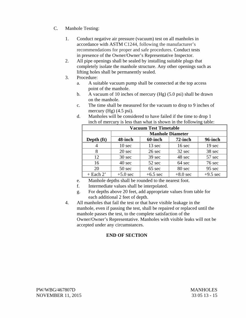
PW/WBG/467807D MANHOLES NOVEMBER 11, 2015 33 05 13 - 15
C. Manhole Testing:
1. Conduct negative air pressure (vacuum) test on all manholes in accordance with ASTM C1244, following the manufacturer’s recommendations for proper and safe procedures. Conduct tests in presence of the Owner/Owner’s Representative Inspector.
2. All pipe openings shall be sealed by installing suitable plugs that completely isolate the manhole structure. Any other openings such as lifting holes shall be permanently sealed.
3. Procedure: a. A suitable vacuum pump shall be connected at the top access
point of the manhole. b. A vacuum of 10 inches of mercury (Hg) (5.0 psi) shall be drawn
on the manhole. c. The time shall be measured for the vacuum to drop to 9 inches of
mercury (Hg) (4.5 psi). d. Manholes will be considered to have failed if the time to drop 1
inch of mercury is less than what is shown in the following table: Vacuum Test Timetable
Depth (ft) Manhole Diameter
48-inch 60-inch 72-inch 96-inch 4 10 sec 13 sec 16 sec 19 sec 8 20 sec 26 sec 32 sec 38 sec 12 30 sec 39 sec 48 sec 57 sec 16 40 sec 52 sec 64 sec 76 sec 20 50 sec 65 sec 80 sec 95 sec
+ Each 2’ +5.0 sec +6.5 sec +8.0 sec +9.5 sec e. Manhole depths shall be rounded to the nearest foot. f. Intermediate values shall be interpolated. g. For depths above 20 feet, add appropriate values from table for
each additional 2 feet of depth. 4. All manholes that fail the test or that have visible leakage in the
manhole, even if passing the test, shall be repaired or replaced until the manhole passes the test, to the complete satisfaction of the Owner/Owner’s Representative. Manholes with visible leaks will not be accepted under any circumstances.
END OF SECTION

PW/WBG/467807D LOW PRESSURE SEWER SYSTEM NOVEMBER 11, 2015 FORCE MAIN PIPING—GENERAL 40 27 00 - 1
SECTION 40 27 00 LOW PRESSURE SEWER SYSTEM FORCE MAIN PIPING—GENERAL
PART 1 GENERAL
1.01 DESIGN REQUIREMENTS
A. Buried Piping: H20-S16 traffic load with 1.5 impact factor, AASHTO HB-17, as applicable.
1.02 DELIVERY, STORAGE, AND HANDLING
A. Flanges: Securely attach metal, hardboard, or wood protectors over entire gasket surface.
B. Threaded or Socket Welding Ends: Fit with metal, wood, or plastic plugs or caps.
C. Linings and Coatings: Prevent excessive drying.
D. Cold Weather Storage: Locate products to prevent coating from freezing to ground.
E. Handling: Use heavy canvas or nylon slings to lift pipe and fittings.
PART 2 PRODUCTS
2.01 PIPING
A. As specified on Piping Data Sheet(s) and Piping Schedule located at the end of this section as Supplement.
B. Installation Location Requirements:
1. All piping within wet well through the adjacent valve vault associated with the low pressure pump station shall be Type 304 or 316 stainless steel. Force main from the low pressure pump station valve vault to the manifolded force main (or discharge point into the ESD system when it is a single connection) shall be ductile iron, high density polyethylene (HDPE) SCH80 PVC, C-900 or SDR pressure pipe as detailed on the Drawings. No alternate materials are acceptable.
2. The manifolded force main shall be ductile iron, high-density polyethylene (HDPE) SCH80 PVC, C-900 or SDR pressure pipe as detailed on the Drawings. No alternate materials are acceptable.
LOW PRESSURE SEWER SYSTEM PW/WBG/467807D FORCE MAIN PIPING—GENERAL NOVEMBER 11, 2015 40 27 00 - 2
C. Diameters Shown:
1. Standardized Products: Nominal size.
D. Joints: See data sheets.
2.02 GASKET LUBRICANT
A. Lubricant shall be supplied by pipe manufacturer and no substitute or “or-equal” will be allowed.
2.03 FABRICATION
A. Mark each pipe length on outside with the following:
1. Size or diameter and class. 2. Manufacturer’s identification and pipe serial number. 3. Location number on laying drawing. 4. Date of manufacture.
B. Code markings according to approved Shop Drawings.
PART 3 EXECUTION
3.01 EXAMINATION
A. Verify size, material, joint types, elevation, horizontal location, and pipe service of existing pipelines to be connected to new pipelines or new equipment.
3.02 PREPARATION
A. Inspect pipe and fittings before installation, clean ends thoroughly, and remove foreign matter and dirt from inside.
3.03 INSTALLATION—GENERAL
A. Join pipe and fittings in accordance with manufacturer’s instructions, unless otherwise shown or specified.
B. Remove foreign objects prior to assembly and installation.
C. Flanged Joints:
1. Install perpendicular to pipe centerline. 2. Bolt Holes: Straddle vertical centerlines, aligned with connecting
equipment flanges or as shown.
PW/WBG/467807D LOW PRESSURE SEWER SYSTEM NOVEMBER 11, 2015 FORCE MAIN PIPING—GENERAL 40 27 00 - 3
3. Use torque-limiting wrenches to ensure uniform bearing and proper bolt tightness.
4. Plastic Flanges: Install annular ring filler gasket at joints of raised-face flange.
5. Grooved Joint Flange Adapters: Include stainless steel washer plates as required for mating to serrated faces and lined valves and equipment.
6. Raised-Face Flanges: Use flat-face flange when joining with flat-faced flange.
7. Verify compatibility of mating flange to adapter flange gasket prior to selecting grooved adapter flanging.
8. Flange fillers are to be avoided, but if necessary, may be used to make up for small angles up to 6 degrees and for filling gaps up to 2 inches between flanges. Stacked flange fillers shall not be used.
9. Threaded flanged joints shall be shop fabricated and delivered to Site with flanges in-place and properly faced.
10. Manufacturer: Same as pipe manufacturer.
D. Threaded and Coupled Joints:
1. Conform to ASME B1.20.1. 2. Produce sufficient thread length to ensure full engagement when
screwed home in fittings. 3. Countersink pipe ends, ream and clean chips and burrs after threading. 4. Make connections with not more than three threads exposed. 5. Lubricate male threads only with thread lubricant or tape as specified on
Piping Data Sheets.
3.04 INSTALLATION—EXPOSED PIPING
A. Install piping so that no load or movement in excess of that stipulated by equipment manufacturer will be imposed upon equipment connection; install to allow for contraction and expansion without stressing pipe, joints, or connected equipment.
3.05 INSTALLATION—BURIED PIPE
A. Placement:
1. Keep trench dry until pipe laying and joining are completed. 2. Pipe Base and Pipe Zone: As specified in Section 31 23 23,
Trench Backfill. 3. Exercise care when lowering pipe into trench to prevent twisting or
damage to pipe. 4. Measure for grade at pipe invert, not at top of pipe.
LOW PRESSURE SEWER SYSTEM PW/WBG/467807D FORCE MAIN PIPING—GENERAL NOVEMBER 11, 2015 40 27 00 - 4
5. Excavate trench bottom and sides of ample dimensions to permit visual inspection and testing of entire flange, valve, or connection.
6. Prevent foreign material from entering pipe during placement. 7. Close and block open end of last laid pipe section when placement
operations are not in progress and at close of day’s work. 8. Lay pipe upgrade with bell ends pointing in direction of laying. 9. After joint has been made, check pipe alignment and grade. 10. Place sufficient pipe zone material to secure pipe from movement
before next joint is installed. 11. Prevent uplift and floating of pipe prior to backfilling.
B. Tolerances:
1. Deflection from Horizontal Line: Maximum 2 inches. 2. Deflection From Vertical Grade: Maximum 1/4 inch. 3. Joint Deflection: Maximum of 25 percent of manufacturer’s
recommendation. 4. Horizontal position of pipe centerline on alignment around curves
maximum variation of 1.75 feet from position shown. 5. Pipe Cover: Minimum 3 feet, unless otherwise shown.
3.06 THRUST RESTRAINT
A. Location: As detailed on the Drawings or otherwise specified.
B. Concrete thrust blocks/restraints shall only be used upon approval of the Owner. Primary restraint method shall not require use of thrust blocks.
3.07 THERMAL EXPANSION
A. For high density polyethylene pipe, force main/piping system shall be designed to accommodate thermal expansion/contraction over the potential range of wastewater and ground temperatures.
B. Install mid span restraints at transitions into structures and where it transitions to ductile iron to prevent the expansion/contraction forces from being transferred to the structure or transition fitting.
3.08 FIELD QUALITY CONTROL
A. Pressure Leakage Testing: As specified in Section 40 80 01, Process Piping Leakage Testing.
PW/WBG/467807D LOW PRESSURE SEWER SYSTEM NOVEMBER 11, 2015 FORCE MAIN PIPING—GENERAL 40 27 00 - 5
3.09 CLEANING
A. Following assembly and testing, and prior to final acceptance, flush pipelines (except as stated below) with water at 2.5 fps minimum flushing velocity until foreign matter is removed.
3.10 SUPPLEMENTS
A. The supplements listed below, following “End of Section,” are a part of this Specification:
1. Pipe Data Sheets.
Number Title
40 27 01 Ductile Iron Pipe and Fittings40 27 02 High Density Polyethylene Pipe and Fittings40 27 03 Polyvinyl Chloride (PVC) Pipe and Fitting 40 27 04 AWWA C900 PVC Pipe and Fittings 40 27 05 SDR Pressure Rated Pipe
END OF SECTION

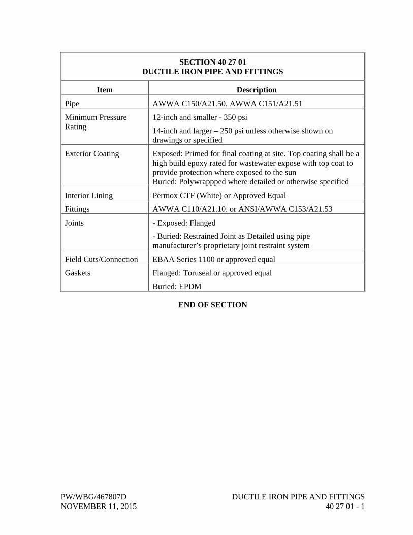
PW/WBG/467807D DUCTILE IRON PIPE AND FITTINGS NOVEMBER 11, 2015 40 27 01 - 1
SECTION 40 27 01 DUCTILE IRON PIPE AND FITTINGS
Item Description
Pipe AWWA C150/A21.50, AWWA C151/A21.51
Minimum Pressure Rating
12-inch and smaller - 350 psi
14-inch and larger – 250 psi unless otherwise shown on drawings or specified
Exterior Coating Exposed: Primed for final coating at site. Top coating shall be a high build epoxy rated for wastewater expose with top coat to provide protection where exposed to the sun Buried: Polywrappped where detailed or otherwise specified
Interior Lining Permox CTF (White) or Approved Equal
Fittings AWWA C110/A21.10. or ANSI/AWWA C153/A21.53
Joints - Exposed: Flanged
- Buried: Restrained Joint as Detailed using pipe manufacturer’s proprietary joint restraint system
Field Cuts/Connection EBAA Series 1100 or approved equal
Gaskets Flanged: Toruseal or approved equal
Buried: EPDM
END OF SECTION

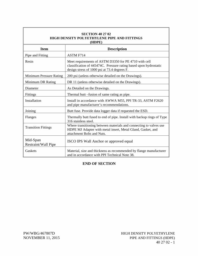
PW/WBG/467807D HIGH DENSITY POLYETHYLENE NOVEMBER 11, 2015 PIPE AND FITTINGS (HDPE) 40 27 02 - 1
SECTION 40 27 02 HIGH DENSITY POLYETHYLENE PIPE AND FITTINGS
(HDPE)
Item Description
Pipe and Fitting ASTM F714
Resin Meet requirements of ASTM D3350 for PE 4710 with cell classification of 445474C. Pressure rating based upon hydrostatic design stress of 1000 psi at 73.4 degrees F.
Minimum Pressure Rating 200 psi (unless otherwise detailed on the Drawings).
Minimum DR Rating DR 11 (unless otherwise detailed on the Drawings).
Diameter As Detailed on the Drawings.
Fittings Thermal butt –fusion of same rating as pipe.
Installation Install in accordance with AWWA M55, PPI TR-33, ASTM F2620 and pipe manufacturer’s recommendations.
Joining Butt fuse. Provide data logger data if requested the ESD.
Flanges Thermally butt fused to end of pipe. Install with backup rings of Type 316 stainless steel.
Transition Fittings Where transitioning between materials and connecting to valves use HDPE MJ Adapter with metal insert, Metal Gland, Gasket, and attachment Bolts and Nuts.
Mid-Span Restraint/Wall Pipe
ISCO IPS Wall Anchor or approved equal
Gaskets Material, size and thickness as recommended by flange manufacturer and in accordance with PPI Technical Note 38.
END OF SECTION

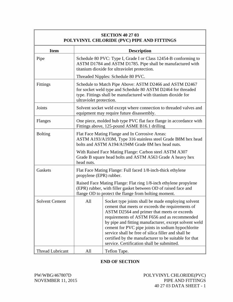
PW/WBG/467807D POLYVINYL CHLORIDE(PVC) NOVEMBER 11, 2015 PIPE AND FITTINGS 40 27 03 DATA SHEET - 1
SECTION 40 27 03 POLYVINYL CHLORIDE (PVC) PIPE AND FITTINGS
Item Description
Pipe Schedule 80 PVC: Type I, Grade I or Class 12454-B conforming to ASTM D1784 and ASTM D1785. Pipe shall be manufactured with titanium dioxide for ultraviolet protection.
Threaded Nipples: Schedule 80 PVC.
Fittings Schedule to Match Pipe Above: ASTM D2466 and ASTM D2467 for socket weld type and Schedule 80 ASTM D2464 for threaded type. Fittings shall be manufactured with titanium dioxide for ultraviolet protection.
Joints Solvent socket weld except where connection to threaded valves and equipment may require future disassembly.
Flanges One piece, molded hub type PVC flat face flange in accordance with Fittings above, 125-pound ASME B16.1 drilling
Bolting Flat Face Mating Flange and In Corrosive Areas: ASTM A193/A193M, Type 316 stainless steel Grade B8M hex head bolts and ASTM A194/A194M Grade 8M hex head nuts.
With Raised Face Mating Flange: Carbon steel ASTM A307 Grade B square head bolts and ASTM A563 Grade A heavy hex head nuts.
Gaskets Flat Face Mating Flange: Full faced 1/8-inch-thick ethylene propylene (EPR) rubber.
Raised Face Mating Flange: Flat ring 1/8-inch ethylene propylene (EPR) rubber, with filler gasket between OD of raised face and flange OD to protect the flange from bolting moment.
Solvent Cement All Socket type joints shall be made employing solvent cement that meets or exceeds the requirements of ASTM D2564 and primer that meets or exceeds requirements of ASTM F656 and as recommended by pipe and fitting manufacturer, except solvent weld cement for PVC pipe joints in sodium hypochlorite service shall be free of silica filler and shall be certified by the manufacturer to be suitable for that service. Certification shall be submitted.
Thread Lubricant All Teflon Tape.
END OF SECTION

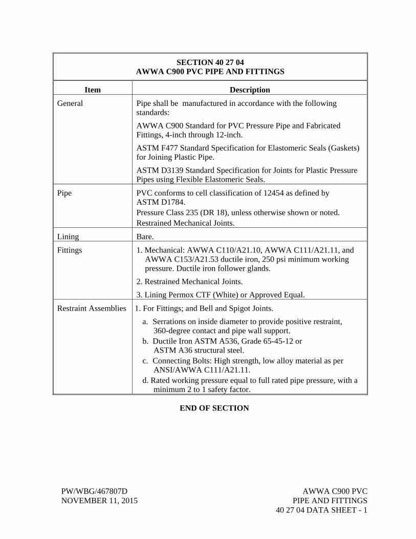
PW/WBG/467807D AWWA C900 PVC NOVEMBER 11, 2015 PIPE AND FITTINGS 40 27 04 DATA SHEET - 1
SECTION 40 27 04 AWWA C900 PVC PIPE AND FITTINGS
Item Description
General Pipe shall be manufactured in accordance with the following standards:
AWWA C900 Standard for PVC Pressure Pipe and Fabricated Fittings, 4-inch through 12-inch.
ASTM F477 Standard Specification for Elastomeric Seals (Gaskets) for Joining Plastic Pipe.
ASTM D3139 Standard Specification for Joints for Plastic Pressure Pipes using Flexible Elastomeric Seals.
Pipe PVC conforms to cell classification of 12454 as defined by ASTM D1784. Pressure Class 235 (DR 18), unless otherwise shown or noted. Restrained Mechanical Joints.
Lining Bare.
Fittings 1. Mechanical: AWWA C110/A21.10, AWWA C111/A21.11, and AWWA C153/A21.53 ductile iron, 250 psi minimum working pressure. Ductile iron follower glands.
2. Restrained Mechanical Joints.
3. Lining Permox CTF (White) or Approved Equal.
Restraint Assemblies 1. For Fittings; and Bell and Spigot Joints.
a. Serrations on inside diameter to provide positive restraint, 360-degree contact and pipe wall support.
b. Ductile Iron ASTM A536, Grade 65-45-12 or ASTM A36 structural steel.
c. Connecting Bolts: High strength, low alloy material as per ANSI/AWWA C111/A21.11.
d. Rated working pressure equal to full rated pipe pressure, with a minimum 2 to 1 safety factor.
END OF SECTION

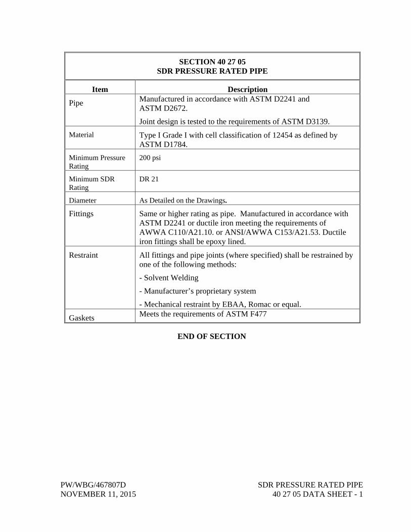
PW/WBG/467807D SDR PRESSURE RATED PIPE NOVEMBER 11, 2015 40 27 05 DATA SHEET - 1
SECTION 40 27 05 SDR PRESSURE RATED PIPE
Item Description
Pipe Manufactured in accordance with ASTM D2241 and ASTM D2672.
Joint design is tested to the requirements of ASTM D3139.
Material Type I Grade I with cell classification of 12454 as defined by ASTM D1784.
Minimum Pressure Rating
200 psi
Minimum SDR Rating
DR 21
Diameter As Detailed on the Drawings.
Fittings Same or higher rating as pipe. Manufactured in accordance with ASTM D2241 or ductile iron meeting the requirements of AWWA C110/A21.10. or ANSI/AWWA C153/A21.53. Ductile iron fittings shall be epoxy lined.
Restraint All fittings and pipe joints (where specified) shall be restrained by one of the following methods:
- Solvent Welding
- Manufacturer’s proprietary system
- Mechanical restraint by EBAA, Romac or equal.
Gaskets Meets the requirements of ASTM F477
END OF SECTION

PW/WBG/467807D VALVES AND OPERATORS NOVEMBER 12, 2015 40 27 20 - 1
SECTION 40 27 20 VALVES AND OPERATORS
PART 1 GENERAL
1.01 REFERENCES
A. The following is a list of standards which may be referenced in this section:
1. American Society of Mechanical Engineers (ASME): a. B16.1, Gray Iron Pipe Flanges and Flanged Fittings: Classes 25,
125, and 250. 2. American Water Works Association (AWWA):
a. C111/A21.11, Rubber-Gasket Joints for Ductile-Iron Pressure Pipe and Fittings.
b. C508, Swing-Check Valves for Waterworks Service, 2-In. Through 24-In. (50-mm Through 600-mm) NPS.
c. C509, Resilient-Seated Gate Valves for Water Supply Service. d. C510, Double Check Valve Backflow Prevention Assembly. e. C512, Air-Release, Air/Vacuum, and Combination Air Valves for
Waterworks Service. f. C542, Electric Motor Actuators for Valves and Slide Gates. g. C550, Protective Interior Coatings for Valves and Hydrants.
3. ASTM International (ASTM): a. A276, Standard Specification for Stainless Steel Bars and Shapes. b. A351/A351M, Standard Specification for Castings, Austenitic, for
Pressure-Containing Parts. c. A380, Standard Practice for Cleaning, Descaling, and Passivation
of Stainless Steel Parts, Equipment, and Systems. d. A564/A564M, Standard Specification for Hot-Rolled and Cold-
Finished Age-Hardening Stainless Steel Bars and Shapes.
PART 2 PRODUCTS
2.01 GENERAL
A. Valves to include operator, handwheel, extension stem, floor stand, operating nut, wrench, and accessories to allow a complete operation from the intended operating level.
B. Valve to be suitable for intended service. Renewable parts not to be of a lower quality than specified.
VALVES AND OPERATORS PW/WBG/467807D 40 27 20 - 2 NOVEMBER 12, 2015
C. Valve same size as adjoining pipe, unless otherwise called out on Drawings or in Supplements.
D. Valve ends to suit adjacent piping.
E. Resilient seated valves shall have no leakage (drip-tight) in either direction at valve rated design pressure. All other valves shall have no leakage (drip-tight) in either direction at valve rated design pressure.
F. Size operators and actuators to operate valve for full range of pressures and velocities.
G. Valve to open by turning counterclockwise, unless otherwise specified.
H. Factory mount operator, actuator, and accessories.
2.02 FACTORY FINISHING
A. General:
1. Interior coatings for valves and hydrants shall be in accordance with AWWA C550, unless otherwise specified.
2. Exterior coating for valves and hydrants shall be manufacturer recommended for corrosive environments and/or direct burial.
2.03 VALVES
A. Type V100 Gate Valve 3 Inches and Smaller
1. All-bronze, screwed bonnet, packed gland, single solid wedge gate, nonrising stem, Class 125 rated 200 psi CWP, complies with MSS SP-80 Type 1.
2. Manufacturers and Products: a. Crane; Figure 438, NPT threaded ends. b. Stockham; Figure B103, NPT threaded ends. c. Crane; Figure 1324, soldered ends.
B. Type V134 Resilient Seated Ductile Iron Gate Valve 3 Inches to 12 Inches:
1. Ductile iron body, resilient seat, bronze stem and stem nut, ASME B16.1 Class 125 flanged ends, nonrising stem, in accordance with AWWA C515, minimum design working water pressure 200 psig, full port, fusion epoxy coated inside and outside per AWWA C550. NSF/ANSI 61 certified where required for the installation location.
2. Manufacturers and Products: a. American Flow Control; Series 2500. b. M&H; Style 7000 and C515 Large RW Valves.
PW/WBG/467807D VALVES AND OPERATORS NOVEMBER 12, 2015 40 27 20 - 3
C. Type V135 Resilient Seated Ductile Iron Gate Valve 3 Inches to 36 Inches:
1. Ductile iron body, resilient seat, bronze stem and stem nut, mechanical joint ends, nonrising stem, in accordance with AWWA C515, minimum design working water pressure 200 psig, full port, fusion epoxy coated inside and outside per AWWA C550. NSF/ANSI 61 certified where required for the installation location.
2. Manufacturers and Products: a. American Flow Control; Series 2500. b. M&H; Style 7000 and C515 Large RW Valves.
D. Type V301 Ball Valve 2 Inches and Smaller:
1. Two-piece, full port, NPT threaded ends, bronze body and end piece, stainless steel ball and stem, RTFE seats and packing, blowout-proof stem, adjustable packing gland, zinc-coated steel hand lever operator with vinyl grip, rated 600-pound WOG, 150-pound SWP, complies with MSS SP-110.
2. Manufacturers and Products: a. Threaded:
1) Conbraco Apollo; 77-100. 2) Nibco; T-585-70.
E. Plug Valves:
1. Type V405 Eccentric Plug Valve 3 Inches to 12 Inches: a. Nonlubricated type rated 175 psig CWP, drip-tight shutoff with
pressure from either direction, cast-iron body, exposed service flanged ends per ASME B16.1 or grooved ends in accordance with AWWA C606 for rigid joints
b. Buried service mechanical joint ends, exposed service flanged, unless otherwise shown.
c. Plug cast iron with round or rectangular port of no less than 100 percent (full port) of connecting pipe area and coated with Buna-N, seats welded nickel, stem bearings lubricated stainless steel or bronze, stem seal multiple V-rings, or U-cups with O-rings of nitrile rubber, grit seals on both upper and lower bearings.
d. For buried service, provide external epoxy coating. e. For exposed service provided primed for coating. f. Operators:
1) 3-Inch to 4-Inch Valves: Wrench lever manual.
VALVES AND OPERATORS PW/WBG/467807D 40 27 20 - 4 NOVEMBER 12, 2015
2) 6-Inch to 12-Inch Valves: Totally enclosed, geared, manual operator with handwheel, 2-inch nut. Size operator for 1.5 times maximum operating shutoff pressure differential for direct and reverse pressure, whichever is higher. For buried service, provide completely sealed operator filled with heavy lubricant and 2-inch nut.
g. Manufacturers and Products: 1) DeZurik; Style PEF. 2) Milliken; Millcentric.
F. Check and Flap Valves:
1. Type V632 Ball Check Valve 3 Inches and Larger: a. Cast iron body with epoxy coating or bronze body. b. Suitable for wastewater service. c. Threaded female x female connection. d. Rated 150-pound working pressure. e. Suitable for vertical up or horizontal flow. f. Bolted or threaded access cover.
2. Manufacturers and Products a. Flowmatic Corp, 508. b. Golden Anderson, 240-T.
3. Type V705 Swing Check Valve 2 Inches to 12 Inches: a. AWWA C508, 125-pound flanged ends, cast-iron body, bronze
body seat, bronze mounted cast-iron clapper with rubber facing, stainless steel hinge shaft.
b. Valves, 2 inches through 12 inches rated 175-pound WWP and 14 inches through 24 inches rated 150-pound WWP. Valves to be fitted with adjustable outside lever and weight. Increasing-pattern body valve may be used where increased outlet piping size is shown.
c. Manufacturers and Products: 1) M&H Valve; Style 59, 159, or 259. 2) Mueller Co.; No. A-2600 Series. 3) CCNE.
G. Self-Regulated Automatic Valves:
1. Type V750, Sewage Air and Vacuum Valve 2 Inches to 8 Inches (Combination Valve): a. Suitable for sewage service; automatically exhausts air during
system filling and allows air to re-enter during draining or when vacuum occurs.
b. Rated working pressure of 150 psi with operating pressure and orifice size as indicated on Drawings.
c. Materials: Cast or Ductile iron with fusion bonded epoxy coating or stainless steel.
PW/WBG/467807D VALVES AND OPERATORS NOVEMBER 12, 2015 40 27 20 - 5
d. Sewage air and vacuum valve fitted with: 1) Blowoff valve. 2) Isolation valve, V134 or V301. 3) Flushing valve with quick disconnect couplings, and a
minimum 5 feet of hose with quick disconnect couplings to permit backflushing after installation without dismantling valve.
e. Manufacturers and Products: 1) ARI, D-023 2) Val-Matic Valve; Series 301 to 306.
2. Type V752 Sewage Air Release Valve 2 Inches to 4 Inches: a. Suitable for sewage service; automatically exhausts entrained air
that accumulates in a system. b. Rated working pressure of 150 psi, operating pressure and orifice
size as indicted on Drawings. c. Materials: Cast or Ductile iron with fusion bonded epoxy coating
or stainless steel d. Sewage air release valve fitted wit:
1) Blowoff valve. 2) Isolation valve, V134 or V301. 3) Flushing valve with quick disconnect couplings, and a
minimum 5 feet of hose with quick disconnect couplings to permit backflushing after installation without dismantling valve.
e. Manufacturers and Products: 1) ARI, D-020 or S-020 2) Val-Matic Valve; Series 48 or 49.
2.04 ACCESSORIES
A. Cast-Iron Valve Box: Designed for traffic loads, sliding type, with minimum of 5-1/4-inch ID shaft.
1. Box: Cast iron with minimum depth of 9 inches. 2. Lid: Cast iron, minimum depth 3 inches, nonlocking type, marked
SEWER. 3. Extensions cast iron. 4. Two-piece box and lid for valves 4 inches through 12 inches,
three-piece box and lid for valves larger than 12 inches with base sized for valve.
5. Valve extension stem for valves with operating nuts 3 feet or greater below finish grade.
6. Manufacturers and Products: a. East Jordan Iron Works; Cast-Iron Valve Boxes. b. Bingham & Taylor; Cast-Iron Valve Boxes.
VALVES AND OPERATORS PW/WBG/467807D 40 27 20 - 6 NOVEMBER 12, 2015
PART 3 EXECUTION
3.01 INSTALLATION
A. Flange Ends:
1. Flanged valve bolt holes shall straddle vertical centerline of pipe. 2. Clean flanged faces, insert gasket and bolts, and tighten nuts
progressively and uniformly.
B. Screwed Ends:
1. Clean threads by wire brushing or swabbing. 2. Apply joint compound.
C. Valve Installation and Orientation:
1. General: a. Install valves so handles operate from fully open to fully closed
without encountering obstructions. b. Install valves in location for easy access for routine operation and
maintenance. c. Install valves per manufacturer’s recommendations.
2. Eccentric Plug Valves: a. Unless otherwise restricted or shown on Drawings, install valve as
follows: Install valve in horizontal position with seat in highest portion of valve (seat up).
3. Check Valves: Install swing check valve with shaft in horizontal position.
4. Self Regulated Automatic Valves: a. Install on a tee. Installation on tap is not allowed. b. Install with isolation valve in accordance with detail.
D. Locate valve to provide accessibility for control and maintenance. Install access doors in finished walls and plaster ceilings for valve access.
E. Extension Stem for Operator: Where depth of valve operating nut is 3 feet or greater below finish grade, furnish operating extension stem with 2-inch operating nut to bring operating nut to a point within 6 inches of finish grade.
3.02 TESTS AND INSPECTION
A. Valve may be either tested while testing pipelines, or as a separate step.
B. Test that valves open and close smoothly under operating pressure conditions. Test that two-way valves open and close smoothly under operating pressure conditions from both directions.

PW/WBG/467807D VALVES AND OPERATORS NOVEMBER 12, 2015 40 27 20 - 7
C. Inspect air and vacuum valves as pipe is being filled to verify venting and seating is fully functional.
D. Count and record number of turns to open and close valve; account for discrepancies with manufacturer’s data.
END OF SECTION

PW/WBG/467807D PIPING LEAKAGE TESTING NOVEMBER 11, 2015 40 80 01 - 1
SECTION 40 80 01 PIPING LEAKAGE TESTING
PART 1 GENERAL (NOT USED)
PART 2 PRODUCTS (NOT USED)
PART 3 EXECUTION
3.01 PREPARATION
A. Develop and review testing procedure with piping system manufacturer.
B. Notify the Owner/Owner’s Representative in writing 5 days in advance of testing. Perform testing in presence of the Owner/Owner’s Representative.
C. Pressure Piping:
1. Install temporary thrust blocking or other restraint as necessary to protect adjacent piping or equipment and make taps in piping prior to testing.
2. Wait 10 days minimum after concrete thrust blocking is installed to perform pressure tests. If high-early strength cement is used for thrust blocking, wait may be reduced to 2 days.
3. Prior to test, remove or suitably isolate appurtenant instruments or devices that could be damaged by pressure testing.
4. Test Pressure: As Detailed on the Drawings.
D. Test section may be filled with water and allowed to stand under low pressure prior to testing.
3.02 HYDROSTATIC TEST
A. General:
1. Testing of pipe shall be accomplished before grouting pipe in any casings.
2. Test newly installed pipelines. Using water as test medium, pipes shall successfully pass a leakage test prior to acceptance.
3. Furnish testing equipment and perform tests in manner satisfactory to Engineer. Testing equipment shall provide observable and accurate measurements of leakage under specified conditions.
4. Supply temporary water for completion of test. 5. Dispose of water used in testing in accordance with applicable
regulations.
PIPING LEAKAGE TESTING PW/WBG/467807D 40 80 01 - 2 NOVEMBER 11, 2015
6. Procedure: a. Maximum filling velocity shall not exceed 0.25 foot per second,
calculated based on the full area of pipe. b. Expel air from pipe system during filling. Expel air through air
release valve or through corporation stop installed at high points and other strategic points.
c. Test pressure shall be 150 percent of the operating pressure as measured at the low point.
d. Test as pressure shall be for a minimum of 1 hour. e. Apply and maintain specified test pressure with hydraulic force
pump. Valve off piping system when test pressure is reached. f. If measured leakage exceeds allowable leakage or if leaks are
visible, repair defective pipe section and repeat hydrostatic test. g. For high density polyethylene pipe, test procedure shall be in
accordance with ASTM F2164. 1) Initial Expansion Phase: Add water as required to maintain
test pressure for 4 hours. 2) Test Phase: Reduce pressure by 10 psi and start pressure
test. 3) Test is successful if pressure says within 5 percent of initial
value for 1 hour. 7. Allowable Leakage: Allowable leakage is zero.
3.03 FIELD QUALITY CONTROL
A. Test Report Documentation:
1. Test date. 2. Description and identification of piping tested. 3. Test fluid. 4. Test pressure. 5. Remarks, including:
a. Leaks (type, location). b. Repair/replacement performed to remedy excessive leakage.
END OF SECTION
PW/WBG/467807D BARNES/CRANE PACKAGED LOW PRESSURE NOVEMBER 11, 2015 PUMP STATION 44 42 55A - 1
SECTION 44 42 55A BARNES/CRANE PACKAGED LOW PRESSURE PUMP STATION
PART 1 GENERAL
1.01 DESCRIPTION
A. This Specification detailed the minimum standards and requirements associated with a Barnes/Crane Pumps and Systems Packaged Low Pressure Sewer System (LPSS) Grinder Pump Station.
1.02 WARRANTY
A. The manufacturer shall provide a warranty to the system owner against defects in material and workmanship for a period of 5 years from the date of installation, acceptance and placement of the station into service. This warranty cover the cost of all labor and materials required to correct any defect.
1.03 DELIVERY AND STORAGE
A. System shall not be delivered to the project site more than 90 days prior to facility startup.
B. The Contractor store the system in accordance with the manufacturer’s recommendations.
C. Failure to maintain the system in like-new condition prior to installation, startup and acceptance will be cause for rejection and replacement of the system.
PART 2 PRODUCTS
2.01 PRODUCTS
A. Packaged low pressure grinder systems shall be by:
1. Barnes / Crane Pumps and Systems 205-987-3337.
2. No equal or alternate.
2.02 PACKAGED SYSTEM REQUIREMENTS
A. Safety:
1. All maintenance tasks for the grinder pump station must be possible without entry into the grinder pump station.
BARNES/CRANE PACKAGED LOW PRESSURE PW/WBG/467807D PUMP STATION NOVEMBER 11, 2015 44 42 55A - 2
2. The grinder pump shall be free from electrical and fire hazards. The grinder pump shall be listed by Underwriters Laboratories, Inc. (UL), to be safe and appropriate for the intended use.
3. The grinder pump shall meet accepted standards for plumbing equipment for use in or near residences, shall be free from noise, odor, or health hazards, and shall have been tested by an independent laboratory to certify its capability to perform as specified in either individual or low pressure sewer system applications.
B. Wet Well and Associated Piping:
1. Minimum of 200 gallons of storage above Pump Off level for residences. Larger wet well may be required by the Designer/Engineer to provide additional storage/working volume. Storage for commercial facilities shall be determined and specified by the Designer/Engineer.
2. Wet well shall be constructed of fiberglass and include PVC or rubber Adapt-a-Flex inlet flange/connection to accept the service line. Connection shall prevent the introduction of inflow/infiltration.
3. Include a lockable or bolt down cover assembly providing low profile mounting and watertight capability. The diamond plate aluminum cover shall have a minimum load rating of 400 pounds per square foot. Cover shall be gasketed with an integral hinged hatch with stainless steel slamlock and PVC slam lock spacer. The PVC spacer must have a threaded plug the slam lock key fits into for removal. Slam lock key shall be placed inside alarm panel at start-up. Hatch shall have stainless steel hold-open chain to hold open hatch at 10 degrees past 90 degrees, and cover shall be powder-coated forest green after fabrication. Where installed in a location subject to higher loadings or traffic the wet well shall be rated for the installation location/conditions.
4. To prevent sewage gases from accumulating in the tank, venting of the station shall be accomplished by building plumbing per all relevant codes.
5. In areas with high water table wet well shall include an extended base or alternate design for placement of concrete ballast to prevent floating.
6. Removal of pumps and / or operation of discharge valve shall not require personnel entry into the tank.
7. The power and control cable shall enter the tank through a factory installed watertight strain relief connector. An electrical junction box shall not be permitted in the tank.
PW/WBG/467807D BARNES/CRANE PACKAGED LOW PRESSURE NOVEMBER 11, 2015 PUMP STATION 44 42 55A - 3
8. All discharge fittings and piping shall be constructed of stainless steel. Each station shall incorporate an all stainless steel “Quick Removal” system consisting of Schedule 40 stainless steel 1-1/4-inch pipe, stainless steel pitless adapter with “T” handle and 1/4-inch stainless steel pet cock with stainless steel street 90 used for recirculation/anti-siphoning/air release; a 1-1/4-inch stainless steel flexible discharge with stainless steel check valve, stainless steel close coupled with 1/4-inch stainless steel nipple and cap, and stainless steel ball valve. A separate 12-inch poly meter box with green top with letters “SEWER” shall be provided to cover valve assembly.
9. The pump discharge shall be equipped with a factory installed, integral check valve built into the discharge piping.
10. The pump discharge shall be equipped with a factory-installed, gravity-operated, flapper-type integral anti-siphon valve built into the discharge piping.
C. Pumps:
1. Rating and capacity shall be provided by the Designer/Engineer. 2. Manufacturers/Products: Barnes Omni Grinder Plus, Centrifugal
Grinder Pump.
D. Power and Control Cables:
1. The power and control cables shall be of the appropriate length to connect the wet well to the pump control panel without causing stress on the cables.
2. The power and control cables shall not be spliced between the wet well and pump control panel.
3. The cables shall be UL / CSA listed and approved. 4. The conduit ends shall be sealed at each end with non-hardening duct
sealant or equal. 5. Connection of power and control cables at the wet well shall be a sealed
watertight connection. 6. Power cable shall be sealed at the motor to meet UL requirements and
clamped in place with a rubber watertight seal bushing or equal to seal the outer jacket against leakage and to provide for strain relief. Cables shall withstand a minimum pull force of 300 pound.
E. Controls:
1. All necessary motor starting controls shall be located in the pump unit. 2. Wastewater level sensing controls shall be housed in a separate
enclosure from motor starting controls. Level sensing control housing shall be integrally attached to pump assembly so that it may be removed from the station with the pump. Attachment and level sensor design shall minimize the potential for the accumulation of grease and debris accumulation, etc.
BARNES/CRANE PACKAGED LOW PRESSURE PW/WBG/467807D PUMP STATION NOVEMBER 11, 2015 44 42 55A - 4
3. High and low controls for controlling pump operation shall be accomplished by a liquid level switch tethered and integral to the pump. High-level alarm sensing will be accomplished by an additional and separate liquid level switch, also tethered to the pump at a higher elevation.
4. All fasteners throughout the assembly shall be 300 Series stainless steel. 5. Pump ON/OFF and high-level alarm functions shall not be controlled by
the same switch.
F. Alarm Panel:
1. General: The alarm panel shall include comprehensive monitoring and control system for the grinder pumping stations as described herein. All equipment is to be completely factory assembled, wired and tested prior to shipment. This comprehensive residential pump control and monitoring system shall have the ability to communicate via three customer selectable methods 1) work only on the customer’s Wi-Fi network. 2) Work on a dedicated Verizon cellular plan, or 3) work on the customer Wi-Fi network, and if Wi-Fi is not available for any reason, it automatically reverts to Verizon cellular backup service for remote alarming and communication.
2. System: The equipment provided shall be a completely integrated automatic monitoring and control system consisting of the required power equipment (circuit breakers, transformers etc.), automation and alarm monitoring equipment in a factory wired and tested assembly. The entire system software will be fully configurable by the owner, using a simple fill-in-the-blank configuration method via iPhone or Android phone.
3. Control Capabilities: The system shall be optimized for advanced residential pump station control, monitoring, personnel notification, and ease of use. The completed system shall provide the following standard calculations, presented in a user-friendly graphical format, viewable from any iPhone or Android phone. Well(s) Level. Well(s) level high and low alarms. Low backup battery. Power Failure. Well drawdown rate (using automatic timed well drawdown tests). Pump amp draw. Pump on/off cycles. Pump runtime. Pump failure. Pump on/off automatic pump control from well(s) level.
PW/WBG/467807D BARNES/CRANE PACKAGED LOW PRESSURE NOVEMBER 11, 2015 PUMP STATION 44 42 55A - 5
Daily Time stamps of when alarm events occurred, and who responded.
Cellular and Wi-Fi signal strength indication. Alarm notification using e-mail, text message, and via the phone
app. Historical log showing all alarm history and water level. Phone-based graphs of historical data that can also be exported to
Microsoft Word or Excel programs.
At each pump station provide: 1-Weatherproof polycarbonate enclosure. 1- Operator Interface display and keypad 1-Surge Arrestor. 1- Remote Telemetry Unit. 1-Power supply, charger, backup rechargeable Li-Ion battery and
filter. 1-WINGS Cellular/Wi-Fi Modem. 1- pump amp probe. 1-12V dc power supply. 1- High gain phantom antenna for Wi-Fi and cellular backup. 1- Bluetooth wireless diagnostic port. 1- USB external comm port.
4. Products: A Microprocessor-based Controller Unit shall be provided for monitoring and control of the pump stations based on alarm contact closures, voltage input signals, analog signals, and relay outputs. a. The controller shall accept (4) Digital Inputs configurable to
monitor dry contacts two (2) of these inputs convertible to act as pulse counters; (1) 4-20mA isolated analog input, (1) 20 amp relay output, (1) internal/external antenna switch, and (1) push-to-test button in its base form.
b. Li-Ion Battery: On-board 7.2VDC, 1800mAH Li-Ion battery provides backup for up to 4 hours in the event of power loss. Battery is automatically recharged using temperature compensated battery charging circuit.
c. One 20 amp Control Relay: Heavy duty 20 amp control relays are used to control the pump and one alarm light/horn based upon water level. Pump control relay shall have adjustable control direction, set points, and dead bands. A dedicated “level simulation button” is used to manually activate relays and determine proper operation. A dedicated “level setpoint” key allows simple adjustment of on/off setpoints without the need for laptop computers or complex re-programming via iPhone or Android smart phone app.
BARNES/CRANE PACKAGED LOW PRESSURE PW/WBG/467807D PUMP STATION NOVEMBER 11, 2015 44 42 55A - 6
d. Indicator LEDs: Surface mount, high visibility LEDs shall indicate the on/off channel status on each of the 4 digital inputs, as well as indicate suitable cellular signal strength, and low back-up battery voltage. The state of these local LED indicators are replicated on the customer smart phone app for easy identification of critical conditions.
e. USB port & Bluetooth Wireless Interface: The system shall contain an externally accessible USB port, and an internal wireless Bluetooth wireless interface for system diagnostics and localized reporting when a customer or technician requires more diagnostic information. The localized USB port allows a technician to connect to the device using a smart phone app and trouble shoot Wi-Fi connection issues, as well as configure alarm call out sequences, historical logs, and other system diagnostic information. Systems that rely solely on Wi-Fi for a connection will not be acceptable due to wireless connection failures during power failure conditions, router configuration issues, and wireless reception issues.
f. Flash memory: Trend log data from connected variables shall be stored on the flash memory for later retrieval via customer app or Bluetooth interface. Memory shall have the ability to be used for updates to the RTU operating system eliminating the need for field laptop computers to repair operating program errors. Memory available from 32MB to 1GB.
g. Zero-crossing detector pump start/stop control: The system shall utilize a zero crossing detector circuit which will energize the pump only when the AC power waveform is at the minimum of the sinusodal waveform minimizing pump inrush current and prolonging motor life.
5. Incoming Service and Lightning Arrestor: a. The incoming service for the control system shall be 220 volt,
1 phase, 3 wire, 60 Hertz. A single phase lightning arrestor shall be supplied in the control system and connected to each line of the incoming side of the power input terminals. The arrestor shall protect the control system against damage as the result of transient voltage surges caused by lightning interference, switching loads and power line interference’s. It shall begin shunting to ground at 500-volts maximum.
b. All metering shall be done ahead of the main disconnect and control panel. The meter shall be supplied and installed by the Contractor in accordance with local power company requirements.
PW/WBG/467807D BARNES/CRANE PACKAGED LOW PRESSURE NOVEMBER 11, 2015 PUMP STATION 44 42 55A - 7
c. The electrical service shall be provided by the utility. Electric meter base shall be provided by the owner and installed in accordance with the requirements of the electric utility. A UL rated main disconnect switch, circuit breaker panel, conduit and wiring between the power company termination and the control panel shall be furnished and installed by the contractor. The power supply to the control panels shall be 85-265V ac, one phase, three wire, 60 Hertz.
6. 12V dc Power Supply: a. A regulated 12V dc power supply shall be provided for the panel
and other monitoring system components as required. The power supply shall include a terminal block for incoming AC. The power supply shall be powered from a 120V ac and include tapered charge type battery charging circuitry to maximize battery life. The power supply shall be rated at minimum of 2.0A at 12V dc.
b. The power supply system shall include (1) 7.2 Volt battery sized to allow for 34 hours continued system operation during a power outage.
c. The power supply shall contain a fuse-protected, internal loop power supply capable of providing loop power for up to one internal pump amp probe.
7. Signal Transient Protection: Transient protection shall be provided with all equipment to protect all instrumentation and telemetry devices either receiving or sending signals.
8. Antennas: All antenna shall be provided internal to the alarm panel and does not require installed by the Contractor. a. Systems supplier shall be responsible for installation, set-up,
adjustment and tuning of the wireless connection to provide optimal communications for the system.
b. The antenna installation shall be internal to the enclosure and shall be indoor/outdoor rated.
G. Optional Features/Requirements Where Required by the Designer/Engineer:
1. Generator Receptacle and Auto Transfer: Where specified alarm panel shall include a 20 amp, 250V ac generator receptacle with a spring-loaded, gasketed cover suitably mounted to provide access for connection of an external generator while maintaining a NEMA 4X rating. An automatic transfer switch shall be provided, which automatically switches from AC power to generator power. Power shall be provided to that alarm panel through the generator receptacle whenever power is present at the receptacle, allowing the audible and visual alarms to function normally in generator mode. When power is no longer applied to the generator receptacle, the panel is automatically switched back to the AC Main power. No manual switching within the panel enclosure shall be required to switch from generator power back to AC Main.
BARNES/CRANE PACKAGED LOW PRESSURE PW/WBG/467807D PUMP STATION NOVEMBER 11, 2015 44 42 55A - 8
2. Monitoring and Diagnostic System that includes: a. Light to indicate AC power to the station is satisfactory. b. Pump Run light to indicate pump is operating (light being lit
indicates which pump is running). c. Trouble light indicator and predictive Visual Alarm notification
(“blinking” alarm lamp; clears on Normal cycle. d. High Level Alarm light indicator (for duplex stations light shall
indicate which pump is in alarm). e. Lead/Lag indication (light indicates which pump is lead) for
duplex stations. f. Menu-driven programmable controller with navigation
overlay-type buttons (Enter, Scroll, Up, Down) Normal Operation Light and Mode button for Mode status.
g. Pump Performance menu display of the following pump performance statistics: 1) Real-time Voltage. 2) Real-time Amperage. 3) Real-time Wattage. 4) Minimum/Maximum/Average Voltage. 5) Minimum/Maximum/Average Amperage. 6) Minimum/Maximum/Average Wattage. 7) Minimum/Maximum Run-time. 8) Average Run-time. 9) Last Run-time. 10) Cycle/Event Counter. 11) Run Time Counter (Hour Meter).
h. Diagnostics Menu. i. Initialize System Menu. j. Run Limit Menu. k. Alarm Delay Menu. l. Power Delay Menu. m. Pump alternating options (no alternation, adjustable time based
and test) for duplex stations.
PART 3 EXECUTION
3.01 DELIVERY
A. All grinder pump units, including level controls, will be delivered to the jobsite 100 percent completely assembled, ready for installation.
B. Grinder pumps will be shipped separately from the tanks.
PW/WBG/467807D BARNES/CRANE PACKAGED LOW PRESSURE NOVEMBER 11, 2015 PUMP STATION 44 42 55A - 9
C. Installing the pumps and discharge piping/hose into the tanks shall be the only assembly step required and allowed due to the workmanship issues associated with other on-site assembly. Grinder pumps must be boxed for ease of handling.
3.02 INSTALLATION OF WET WELL
A. Shall be installed in accordance with the Manufacturer written instruction Specification sections:
1. 31 10 00, Site Clearing. 2. 31 23 16, Excavation. 3. 31 23 19, Dewatering. 4. 31 23 23, Trench Backfill.
B. Where specified a concrete anti-flotation collar or equal shall be installed in accordance with the Designer/Engineer requirements along with those of the Manufacturer.
3.03 STARTUP AND FIELD TESTING
A. The Manufacturer shall provide the services of qualified factory trained technician(s) who shall inspect the placement and wiring of each station, perform field tests as specified herein, and instruct the Owner in the operation and maintenance of the equipment before the stations are accepted by the Owner.
B. Wet well shall be filled with clean water submerging all side wall penetrations prior to backfilling and certify in the presence of the Owner that the wet well is watertight.
C. The authorized factory technician(s) will perform the following on each station.
1. Confirm all valving is open. 2. Turn ON the alarm power circuit and verify the alarm is functioning
properly. 3. Turn ON the pump power circuit. Initiate the pump operation to verify
automatic “on/off” controls are operative. 4. Confirm all monitor controls are operating properly. 5. Manufacturer shall submit detailed results of the tests and a certificate
of proper installation. Final acceptance of the system will not occur until forms have been received for each pump station installed and any installation deficiencies corrected.
BARNES/CRANE PACKAGED LOW PRESSURE PW/WBG/467807D PUMP STATION NOVEMBER 11, 2015 44 42 55A - 10
3.04 MANUFACTURERS SERVICES
A. The Manufacturer shall supply a copy of Operation and Maintenance Manuals to the Owner.
END OF SECTION
PW/WBG/467807D E-ONE PACKAGED LOW PRESSURE NOVEMBER 11, 2015 PUMP STATION 44 42 55B - 1
SECTION 44 42 55B E-ONE PACKAGED LOW PRESSURE PUMP STATION
PART 1 GENERAL
1.01 DESCRIPTION
A. This Specification detailed the minimum standards and requirements associated with an E-One Packaged Low Pressure Sewer System (LPSS) Grinder Pump Station.
1.02 WARRANTY
A. The manufacturer shall provide a warranty to the system owner against defects in material and workmanship for a period of 5 years from the date of installation, acceptance and placement of the station into service. This warranty cover the cost of all labor and materials required to correct any defect.
1.03 DELIVERY AND STORAGE
A. System shall not be delivered to the project site more than 90 days prior to facility startup.
B. The Contractor store the system in accordance with the manufacturer’s recommendations.
C. Failure to maintain the system in like-new condition prior to installation, startup and acceptance will be cause for rejection and replacement of the system.
PART 2 PRODUCTS
2.01 PRODUCTS
A. Packaged low pressure grinder systems shall be by:
1. Environment One Corporation Morrow Water Technologies T: 205.408.6680
2. No equal or alternate.
E-ONE PACKAGED LOW PRESSURE PW/WBG/467807D PUMP STATION NOVEMBER 11, 2015 44 42 55B - 2
2.02 PACKAGED SYSTEM REQUIREMENTS
A. Safety:
1. All maintenance tasks for the grinder pump station must be possible without entry into the grinder pump station
2. The grinder pump shall be free from electrical and fire hazards. The grinder pump station shall be listed by Underwriters Laboratories, Inc. (UL), to be safe and appropriate for the intended use. UL listing of components of the station, or third-party testing to UL standard are not acceptable.
3. The grinder pump shall meet accepted standards for plumbing equipment for use in or near residences, shall be free from noise, odor, or health hazards, and shall have been tested by an independent laboratory to certify its capability to perform as specified in either individual or low pressure sewer system applications.
B. Wet Well and Associated Piping:
1. Minimum of 200 gallons of storage above Pump Off level for residences. Larger wet well may be required by the Designer/Engineer to provide additional storage/working volume. Storage for commercial facilities shall be determined and specified by the Designer/Engineer.
2. Wet well shall be constructed of fiberglass and include PVC or rubber Adapt-a-Flex inlet flange/connection or equal to accept the service line. Connection shall prevent the introduction of inflow/infiltration. Include a lockable or bolt down cover assembly providing low profile mounting and watertight capability. The cover shall have a minimum load rating of 150 pounds per square foot. Where installed in a location subject to higher loadings or traffic the wet well shall be rated for the installation location/conditions.
3. To prevent sewage gases from accumulating in the tank, venting of the station shall be accomplished by building plumbing per all relevant codes.
4. In areas with high water table wet well shall include an extended base or alternate design for placement of concrete ballast to prevent floating.
5. Removal of pumps and / or operation of discharge valve shall not require personnel entry into the tank.
6. The power and control cable shall enter the tank through a factory or field installed watertight strain relief connector. An electrical junction box shall not be permitted in the tank.

PW/WBG/467807D E-ONE PACKAGED LOW PRESSURE NOVEMBER 11, 2015 PUMP STATION 44 42 55B - 3
7. All discharge fittings and piping shall be constructed of SST. Each station shall incorporate an all SST “Quick Removal” system. The pump discharge shall be equipped with a factory installed, integral check valve built into the discharge piping.
8. The pump discharge shall be equipped with a factory-installed, gravity-operated, flapper-type integral anti-siphon valve built into the discharge piping.
C. Pumps:
1. Rating and capacity shall be provided by the Designer/Engineer. 2. Manufacturers/Products:
a. E/One Extreme, Positive Displacement Grinder Pump
D. Power and Control Cables:
1. The power and control cables shall be of the appropriate length to connect the wet well to the pump control panel without causing stress on the cables.
2. The power and control cables shall not be spliced between the wet well and pump control panel.
3. The cables shall be UL / CSA listed and approved. 4. The conduit ends shall be sealed at each end with non-hardening duct
sealant or equal. 5. Connection of power and control cables at the wet well shall be a sealed
watertight connection. 6. Power cable shall be sealed at the motor to meet UL requirements and
clamped in place with a rubber watertight seal bushing or equal to seal the outer jacket against leakage and to provide for strain relief. Cables shall withstand a minimum pull force of 300 pound.
E. Controls:
1. All necessary motor starting controls shall be located in the enclosure of the core unit secured by stainless steel fasteners or equal.
2. Wastewater level sensing controls shall be housed in a separate enclosure from motor starting controls. Level sensing control housing shall be integrally attached to pump assembly so that it may be removed from the station with the pump. Attachment and level sensor design shall minimize the potential for the accumulation of grease and debris accumulation, etc.
E-ONE PACKAGED LOW PRESSURE PW/WBG/467807D PUMP STATION NOVEMBER 11, 2015 44 42 55B - 4
3. High and low controls for controlling pump operation shall be accomplished by monitoring the pressure changes in an integral air column connected to a pressure switch or equal system. Depressing the push to run button must operate the pump even with the level sensor housing removed from the pump. High-level sensing will be accomplished by a separate air column sensor and pressure switch or equal. Closure of the high-level sensing device will energize an alarm circuit as well as a redundant pump-on circuit. To assure reliable operation of the pressure switches, each core shall be equipped with a factory installed equalizer diaphragm that compensates for any atmospheric pressure or temperature changes.
4. All fasteners throughout the assembly shall be 300 Series stainless steel. 5. Pump ON/OFF and high-level alarm functions shall not be controlled by
the same switch. 6. A manual run switch/feature shall be provided.
F. Alarm Panel:
1. Pump station shall include a NEMA 4X, UL-listed alarm panel suitable for wall or pole mounting. The NEMA 4X enclosure shall be manufactured of thermoplastic polyester or equal that is corrosion resist. The enclosure shall include a hinged, lockable cover with padlock, preventing access to electrical components, and creating a secured safety front to allow access only to authorized personnel.
2. The alarm panel shall contain a dedicated, double-pole circuit breaker for the pump core’s power circuit and dedicated 15-amp single-pole circuit breaker for the alarm circuit. The panel shall contain a push-to-run feature, an internal run indicator, and a complete alarm circuit. All circuit boards in the alarm panel shall be protected with a conformal coating on both sides and the AC power circuit shall include an auto resetting fuse.
3. The alarm panel shall include the following features: a. External audible and visual alarm. b. Push-to-run switch. c. Push-to-silence switch. d. Redundant pump start. e. High level alarm capability. f. The alarm sequence is to be as follows when the pump and alarm
breakers are on: 1) When liquid level in the sewage wet-well rises above the
alarm level, the contacts on the alarm pressure switch activate, audible and visual alarms are activated, and the redundant pump starting system is energized.
PW/WBG/467807D E-ONE PACKAGED LOW PRESSURE NOVEMBER 11, 2015 PUMP STATION 44 42 55B - 5
2) The audible alarm may be silenced by means of the externally mounted, push-to-silence button. The audible alarm shall be externally mounted on the bottom of the enclosure, capable of 93 dB at 2 feet. The audible alarm shall be capable of being deactivated by depressing a push-type switch that is encapsulated in a weatherproof silicone boot and mounted on the bottom of the enclosure (push-to-silence button).
3) Visual alarm remains illuminated until the sewage level in the wet-well drops below the “off” setting of the alarm pressure switch. Visual alarm shall be mounted to the top of the enclosure in such a manner as to maintain NEMA 4X rating.
4) The entire alarm panel, as manufactured and including any of the following options shall be UL listed and approved.
g. A placard shall be affixed to the control panel with an emergency phone number for the local pump station representative for use by the owner in an emergency situation.
h. All internal wiring shall be neat and color coded. A schematic wiring diagram shall be permanently affixed to the inside of the panel door.
4. A separate, remote indoor alarm module shall be provided to indicate a high level alarm with or without AC power to the grinder pump station. The Remote Sentry indoor alarm module shall have an internal power source enabling its continued operation without AC power. The Remote Sentry shall have an audible alarm and a visual alarm, both of which shall automatically reset if the high level alarm condition is eliminated. The Remote Sentry indoor alarm module shall include a Silence button for the audible alarm and a Test button.
G. Additional Protections and Requirements:
1. Low Voltage (Brownout) Protection: a. A lockout cycle will prevent the motor from operating and will
illuminate a warning light if the incoming AC Mains voltage drops below a predetermined minimum, typically 12 percent of nameplate (211 volts for a 240 volt system) for 2 to 3 seconds, regardless of whether the motor is running.
b. The lockout cycle will end if the incoming AC Mains voltage returns to a predetermined value, typically 10 percent of nameplate (216 volts for a 240 volt system.
E-ONE PACKAGED LOW PRESSURE PW/WBG/467807D PUMP STATION NOVEMBER 11, 2015 44 42 55B - 6
c. The system continues to retest the voltage every second indefinitely. If the lockout cycle has been initiated and the voltage comes back above the predetermined starting voltage, the system will function normally. The warning light remains illuminated during a Brownout condition and remains latched until the pump breaker is turned off and then on again (reset). The audible and visual alarm will not be activated unless there is a high wastewater level in the tank.
2. Run Dry Protection: a. A 20-minute lockout cycle will prevent the motor from operating
and will illuminate a warning light when the wastewater level in the tank is below the pump inlet level. The condition is rechecked every 20 minutes.
b. If the lockout cycle has been initiated and the condition is satisfied, the pump is allowed to cycle normally but the warning light remain on.
c. The warning light will remain on until the pump breaker is turned off and then on again (reset).
d. If the condition is not satisfied after 3 consecutive attempts, the visual alarm will be activated until the pump breaker is turned off and on (reset) or until there is one cycle of normal operation. If a high level condition is presented at any time, a pump run cycle will be activated.
3. High System Pressure Protection: a. A 20-minute lockout cycle will prevent the motor from operating
and will illuminate a warning light when the pressure in the discharge line is high which is typically a result of a closed valve or line plug. The condition is rechecked every 20 minutes.
b. If the condition is satisfied, the pump is allowed to cycle normally but the warning light remains on.
c. If the condition is not satisfied after 3 consecutive attempts, the pump is locked out indefinitely until the condition is removed and power is reset. The audible and visual alarm will be activated.
d. The warning light will remain on until the pump breaker is turned off and then on again (reset).
H. Main Service Disconnect Breaker: A separate, internal breaker rated and approved for use as “service equipment” and acts as a main service disconnect of the grinder pump station shall be provided.
PW/WBG/467807D E-ONE PACKAGED LOW PRESSURE NOVEMBER 11, 2015 PUMP STATION 44 42 55B - 7
I. Optional Features/Requirements Where Required by the Designer/Engineer:
1. Generator Receptacle and Auto Transfer: Where specified alarm panel shall include a 20 amp, 250V ac generator receptacle with a spring-loaded, gasketed cover suitably mounted to provide access for connection of an external generator while maintaining a NEMA 4X rating. An automatic transfer switch shall be provided, which automatically switches from AC power to generator power. Power shall be provided to that alarm panel through the generator receptacle whenever power is present at the receptacle, allowing the audible and visual alarms to function normally in generator mode. When power is no longer applied to the generator receptacle, the panel is automatically switched back to the AC Main power. No manual switching within the panel enclosure shall be required to switch from generator power back to AC Main.
2. Monitoring and Diagnostic System that includes: a. Light to indicate AC power to the station is satisfactory. b. Pump Run light to indicate pump is operating (light being lit
indicates which pump is running). c. Trouble light indicator and predictive Visual Alarm notification
(“blinking” alarm lamp; clears on Normal cycle. d. High Level Alarm light indicator (for duplex stations light shall
indicate which pump is in alarm). e. Lead/Lag indication (light indicates which pump is lead) for
duplex stations. f. Menu-driven programmable controller with navigation overlay-
type buttons (Enter, Scroll, Up, Down) Normal Operation Light and Mode button for Mode status.
g. Pump Performance menu display of the following pump performance statistics. 1) Real-time Voltage. 2) Real-time Amperage. 3) Real-time Wattage. 4) Minimum/Maximum/Average Voltage. 5) Minimum/Maximum/Average Amperage. 6) Minimum/Maximum/Average Wattage. 7) Minimum/Maximum Run-time. 8) Average Run-time. 9) Last Run-time. 10) Cycle/Event Counter. 11) Run Time Counter (Hour Meter).
h. Diagnostics Menu. i. Initialize System Menu.
E-ONE PACKAGED LOW PRESSURE PW/WBG/467807D PUMP STATION NOVEMBER 11, 2015 44 42 55B - 8
j. Run Limit Menu. k. Alarm Delay Menu. l. Power Delay Menu. m. Pump alternating options (no alternation, adjustable time based
and test) for duplex stations.
PART 3 EXECUTION
3.01 FACTORY TESTING
A. Each grinder pump shall be submerged and operated for 1.5 minutes (minimum). Included in this procedure will be the testing of all ancillary components such as, the anti-siphon valve, check valve, discharge assembly and each unit’s dedicated level controls and motor controls.
B. Actual appurtenances and controls which will be installed in the field for the pumping system shall be used for testing of the pump. Use of a common set of appurtenances and controls for all pumps is not acceptable.
C. Certified test results shall be available upon request showing the operation of each grinder pump at two different points on its curve.
D. Additional validation tests include: integral level control performance, continuity to ground and acoustic tests of the rotating components.
E. All wet wells shall be factory leak tested to assure the integrity of all joints, seams and penetrations. All necessary penetrations such as inlets, discharge fittings and cable connectors shall be included in this test along with their respective sealing means (grommets, gaskets etc.).
F. The Engineer reserves the right to inspect such testing procedures with representatives of the Owner, at the manufacturer’s facility.
3.02 DELIVERY
A. All grinder pump core units, including level controls, will be delivered to the job site 100 percent completely assembled, including testing, ready for installation.
B. Grinder pump cores will be shipped separately from the tanks.
C. Installing the cores and discharge piping/hose into the tanks shall be the only assembly step required and allowed due to the workmanship issues associated with other on-site assembly. Grinder pump cores must be boxed for ease of handling.
PW/WBG/467807D E-ONE PACKAGED LOW PRESSURE NOVEMBER 11, 2015 PUMP STATION 44 42 55B - 9
3.03 INSTALLATION OF WET WELL
A. Shall be installed in accordance with the Manufacturer written instruction and Specification Sections:
1. 31 10 00, Site Clearing. 2. 31 23 16, Excavation. 3. 31 23 19, Dewatering. 4. 31 23 23, Trench Backfill.
B. Where specified a concrete anti-flotation collar or equal shall be installed in accordance with the Designer/Engineer requirements along with those of the Manufacturer.
3.04 STARTUP AND FIELD TESTING
A. The Manufacturer shall provide the services of qualified factory trained technician(s) who shall inspect the placement and wiring of each station, perform field tests as specified herein, and instruct the Owner in the operation and maintenance of the equipment before the stations are accepted by the Owner. Wet well shall be filled with clean water submerging all side wall penetrations prior to backfilling and in the presence of the Owner certify that the wet well is watertight.
B. The authorized factory technician(s) will perform the following test on each station:
1. Confirm all valving is open. 2. Turn ON the alarm power circuit and verify the alarm is functioning
properly. 3. Turn ON the pump power circuit. Initiate the pump operation to verify
automatic “on/off” controls are operative. 4. Confirm all monitor controls are operating properly. 5. Manufacturer shall submit detailed results of the tests and a certificate
of proper installation. Final acceptance of the system will not occur until forms have been received for each pump station installed and any installation deficiencies corrected.
3.05 MANUFACTURERS SERVICES
A. The Manufacturer shall supply a copy of Operation and Maintenance Manuals to the Owner.
END OF SECTION


![· Standard ' Standard' Standard Cost 'Standard Cost ' Quality standard 'Quality standard' Quantity standard 'Quantity standard ' [15 marks] [15 markah] Outline TEN (10) steps of](https://img.pdfslide.us/doc/110x75/5e4ad3aa693c4f498143a31a/standard-standard-standard-cost-standard-cost-quality-standard-quality-standard.jpg)