Embed Size (px)
Citation preview

Comparison of two methods forHydraulic (Infiltration) Design:BRE Digest 365 and CIRIA156
The background calculations for bothmethods are the same:
Calculating run-off
Firstly, calculate the run-off volume that will occur from the site during a designstorm event, of an intensity that could beexpected to occur once in the storm return period.
The greater the soil infiltration rate, theshorter the critical duration will be.
The infiltration system is then designed withsufficient capacity to store this volume ofwater. This normally involves a layout ofAquaCell units with a large surface areaadjacent to the soil.
Checking rate of emptying
The rate of emptying must then bechecked to ensure that the system emptiesin a sensible time – normally taken to be at least half-empty within 24 hours.
The purpose of this test is to ensure thatthe system is empty before the next stormarrives and to avoid problems of waterquality caused by storing the water for too long.
Empty rate is a function of the geotechnicalproperties of the surrounding soil and thewetted area in contact with that soil.
There are significant differences in themethods of calculation between the twomethods. Wavin would advise the user towork with whichever method they find tobe most acceptable or familiar.
However, to facilitate a decision betweenthe two methods, their key differences areset out as follows:
The BRE Method
z Only allows the vertical surface areas tobe considered as releasing water:assumes the base has been clogged by siltation
z Therefore, favours more linear ‘trench’layouts with the runs only 1 unit wide tomaximise the side surface area incontact with the soil
z Takes a simple approach to the issue ofempty-time, assuming a constantoutflow rate based upon calculationsassuming the tank is half full.
Overall effect:
z For shallow tanks: over a given period,the BRE method discharges more waterthan the CIRIA method
z For deep tanks: over a given period, theBRE method discharges less than theCIRIA method.
The CIRIA Method
z Allows both the sides and the base areato be included in the calculations
z Therefore, tends to generate systemswhich are more 3D in shape
z To compensate for the risk of the basebecoming clogged, includes a factor ofsafety in the calculations (ranging from 1.5to 10), the value of which is dependentupon the consequences of failure
z For half emptying time, takes full accountof the wetted surface at a particular timeinstant and thus discharges more waterwhen the tank is full compared to when itis nearly empty.
Overall effect:
z For shallow tanks: over a given period,the CIRIA method discharges less waterthan the BRE method
z For deep tanks: over a given period, theCIRIA method discharges more than theBRE method.
General conclusion
The CIRIA calculations are more accuratebut involve more complex work that is bestcarried out by a computer program.
Further information
To obtain further information about thesemethods, please contact the following:
z For BRE Digest 365: www.bre.co.uk ortelephone 01923 664000
z For CIRIA 156: www.ciria.org.uk ortelephone 0207 222 8891.
APPENDIX: 1 Comparison of two methods for Hydraulic Design
© Published by Wavin Plastics Limited 2002

EXAMPLE 1: Simplifiedapproximate approach toinfiltration
Project details
A new house is to be constructed in anarea with blocky fissured chalk soil, intowhich all stormwater from building andhard surfacing is to be infiltrated. Thebuilding has a plan area of 83 m2 andsurrounding hard surfacing 67m2.
Calculations
Total catchment area = 83 + 67 = 150 m2
Maximum area per box in chalk (Table 2) =7.9m2
AquaCell units required
Number of boxes = 150/7.9 = 19 boxes.
EXAMPLE 2: Design ofattenuation system
Project details
A factory development of 2000m2 totalimpermeable areas has had a dischargeconsent of 3 litres per second placed upon it.
Rainfall levels from the WallingfordProcedure would suggest, in this area forthe desired rainfall return period, a run-offvolume of 122 m3.
Calculations
Total volume discharged in 2 hour period(Table 5) = 21.6 m3
Volume of storage required = 101 m3
If storage is to be 4 units deep (1.6m) thenvolume per layer = 101/4 = 25.25m3/layer
AquaCell units required
From Table 6, this can be achieved by usingeither of the following boxes:
z 17 units long, 8 units wide(25.84m3/layer) (544 boxes)
z 15 units long, 9 units wide(25.65m3/layer) (540 boxes)
z 19 units long, 7 units wide(25.27m3/layer) (532 boxes).
19 x 7 provides the most economic solution,but other solutions may fit the site better.
APPENDIX: 2Worked examples for Hydraulic Design
Soil Type Maximum Impermeable Catchment No. of AquaCell units perArea per AquaCell unit (m2) 100m2 catchment area
Gravel 95.0 2
Sand 14.4 7
Chalk* 7.9 13
Silt 0.475 211
Clay Consult Wavin for project specific information
Table 2 Design parameters for single house roof soakaway
* Blocky, fissured chalk, where fissure flow is dominant. EXCLUDES putty chalk and Chalk Marl.
Discharge (l/s) Volume lost in 120 mins (m3 )
0 0.0
1 7.2
2 14.4
3 21.6
4 28.8
5 36.0
6 43.2
7 50.4
8 57.6
9 64.8
Table 5 Run-off volumes for a 2 hour storm
Number of units wide 1 2 3 4 5 6 7 8 9
1 0.19 0.38 0.57 0.76 0.95 1.14 1.33 1.52 1.71
2 0.38 0.76 1.14 1.52 1.90 2.28 2.66 3.04 3.42
3 0.57 1.14 1.71 2.28 2.85 3.42 3.99 4.56 5.13
4 0.76 1.52 2.28 3.04 3.80 4.56 5.32 6.08 6.84
5 0.95 1.90 2.85 3.80 4.75 5.70 6.65 7.60 8.55
6 1.14 2.28 3.42 4.56 5.70 6.84 7.98 9.12 10.26
7 1.33 2.66 3.99 5.32 6.65 7.98 9.31 10.64 11.97
8 1.52 3.04 4.56 6.08 7.60 9.12 10.64 12.16 13.68
9 1.71 3.42 5.13 6.84 8.55 10.26 11.97 13.68 15.39
10 1.90 3.80 5.70 7.60 9.50 11.40 13.30 15.20 17.10
11 2.09 4.18 6.27 8.36 10.45 12.54 14.63 16.72 18.81
12 2.28 4.56 6.84 9.12 11.40 13.68 15.96 18.24 20.52
13 2.47 4.94 7.41 9.88 12.35 14.82 17.29 19.76 22.23
14 2.66 5.32 7.98 10.64 13.30 15.96 18.62 21.28 23.94
15 2.85 5.70 8.55 11.40 14.25 17.10 19.95 22.80 25.65
16 3.04 6.08 9.12 12.16 15.20 18.24 21.28 24.32 27.36
17 3.23 6.46 9.69 12.92 16.15 19.38 22.61 25.84 29.07
18 3.42 6.84 10.26 13.68 17.10 20.52 23.94 27.36 30.78
19 3.61 7.22 10.83 14.44 18.05 21.66 25.27 28.88 32.49
20 3.80 7.60 11.40 15.20 19.00 22.80 26.60 30.40 34.20
Num
ber
of u
nits
long
Volume in m3
Table 6 Volume (m3) of tank created from the given number of single layer AquaCell units
© Published by Wavin Plastics Limited 2002

The orifice flow control design equationgiven in the main text (see Section 2.3.3.1) isderived from the standard equation (fromBernoulli) for a small orifice. It is only validwhere the orifice is small when comparedwith the head above it, and for a sharpedged orifice. The more general equationis given as:
Where:
Q = Flow rate (m3/s)
Cd = Discharge coefficient dependentupon the orifice shape (0.62 typical)
Ao = Orifice area
g = Acceleration due to gravity, 9.81 m/s2
H = Head of water (m)
APPENDIX: 3 Orifice flow controls
© Published by Wavin Plastics Limited 2002

Design philosophy
Structural testing
The AquaCell units have been tested atSalford University to determine theirstructural capacity. Direct loading testswere carried out on single units todetermine the strength and stiffnessparameters. A long-term 90 day creep testwas also carried out.
A simplified design procedure has beendeveloped for the AquaCell units. This uses the results of the laboratory testing to directly estimate performance under field conditions.
Typical results
Typical results from the laboratory tests todetermine short-term compressive strengthand deflection rates are shown in Fig. A4.1
for vertical compression, and Fig. A4.2 forlateral compression.
The design lines have been determined following the advice provided in ASTM D-1621 – 00
xiii.
Ultimate compressive strength
The ultimate compressive strength isdetermined at the yield point. The short-term vertical deflection of the units underload is obtained from the design line on Fig. A4.1. This value should be used inassessing likely deflections under trafficloads. Design parameters for the AquaCellsystem are given in Table A.
APPENDIX: 4Structural Design Philosophy
© Published by Wavin Plastics Limited 2002
Vertical loading Lateral loadingon top face on side face
Ultimate compressive 560kN/m2
77.5kN/m2
strength at yield
Short term deflection 1mm per 97.0kN/m2
1mm per 7.0kN/m2
applied load applied load
Long term deflection at Deflection (mm) =
up to 10 years, 20˚C, 0.4705Ln (time in hours)
10kN load
Table A Strength and deflection characteristics of AquaCell units
Note: Partial factors of safety as appropriate should be applied to these values for design.
Fig.A4.2 Typical loading test results: lateral
Fig.A4.1 Typical loading test results: vertical

Creep
All plastics creep and the design of anystructure constructed using polymermaterials should take account of it.
Creep testing has been undertaken on theAquaCell units and a typical graph of theresults is shown in Fig. A4.3.
The results of the creep tests can be usedto estimate settlements up to 20 years
xiv.
In locations where settlement is not ofconcern, then designs up to 50 years canbe undertaken.
Ultimate and serviceability limit states
Principles
The philosophy of limit state design is usedin other structural design applications suchas reinforced concrete and steel. Themethod aims to guarantee that a structure(in this case, the AquaCell system) remainssafe and suitable for use at certain limitstates.
Limit states
For the AquaCell units, there are two limitstates:
z Ultimate limit state: when the structurecollapses and is unsafe
z Serviceability limit state: beyond which,although still safe, deflections areexcessive and cause cracking orunacceptable movement in the overlyingsurfacing materials.
Factors of safety
To ensure that the risk of exceeding thelimit states is minimal, factors of safety areapplied to the ultimate compressivestrength and deflection performance of theunits and to the applied loads. These areknown as partial factors of safety.
Material factors
Variables
The ultimate compressive strength of theunits has been obtained from testing onex-works samples. This may be reducedby factors including:
z Variations during manufacture
z Variability and uncertainties in materialstrength (e.g. due to extrapolation of data)
z Damage during installation
z Environmental effects.
APPENDIX: 4 Structural Design Philosophy
Fig.A4.3 Typical structural test results: creep
To take account of these, the designstrength is obtained by dividing the ultimateby a material partial factor of safety Fm,appropriate to the material and limit state.
Adopted guidance
There is no specific guidance on the choice of material factors for plasticstructures such as AquaCell. Therefore the guidance on choice of material factorsfor thermoplastic geogrids used in earthreinforcement has been adopted.
The partial factors of safety in Table B areappropriate for AquaCell, allowing forextrapolation of creep data, fatigue, etc,and are similar to those used for polymerreinforcement used in reinforced soilapplications
xv, xvi.
Temperature
These factors are only applicable intemperate climate conditions such as the UK.
Although the strength of polypropylenedoes vary with temperature, this will not besignificant for installations in the UK. Here,the temperature in the ground, at thetypical depth of installation, remainsbetween 0˚C and 20˚C with a mean valueof around 10˚C
xv, xvii.
Loads and load factors
Loading principles
The loads applied to units can be brokendown into separate elements:
Dead loads are permanent loads applied tothe units. They include:
z The weight of fill placed over the top
z Lateral earth pressure loads acting onthe side of the system.
These factors determine the maximumdepth of installation and maximum coverdepth.
Imposed loads are transient loads due tovehicle or pedestrian traffic andconstruction traffic.
Traffic wheel loads are normally given asstatic loads and a factor is applied to allowfor dynamic effects
xvii.
Design load
The design load is obtained by applying apartial factor of safety to the estimatedcharacteristic load. This allows for:
z Unforeseen variations of loading
z The severity of the consequences of thelimit state occurring.
Limit state Fm
Ultimate limit state 2.75
Serviceability limit state 1.5
Table B Partial factors of safety for material,Fm
© Published by Wavin Plastics Limited 2002

APPENDIX: 4 Structural Design Philosophy
The loads on the units will be similar toloads applied in the design of structuresusing conventional materials such asconcrete. Accordingly, the partial safetyfactors for loads that are appropriate to thedesign of the AquaCell system are takenfrom British Standard BS 8110
xviii and are
provided in Table C.
Thermal expansion
Thermal expansion of the units will benegligible because temperature variationsthat are likely to occur in the ground shouldnot be significant
xv. These loads are not,
therefore, considered in design.
Maximum depth of installation
Limiting factors
The limiting factors that determine themaximum depth of installation are:
z The weight of cover fill and live surcharge loads
z The lateral pressures imposed by theearth and groundwater on the sides ofthe system.
For all of these cases both the ultimate andserviceability limit states must beconsidered:
Weight of cover fill and livesurcharge loads
The pressure on the system due to theweight of cover fill and surcharge σv, isequal to:
σv (kN/m2) = (dγ) + σtraffic
where
d = depth of fill material over units, m
γ = unit weight of fill material, kN/m3
σtraffic = surcharge load, kN/m2
The unit weight of fill material typically lies between 17kN/m3 and 21kN/m3. Noallowance has been made for factors suchas dissipation of load through friction withthe side of the trench, since this dependson very tight site control over installationwhich cannot generally be guaranteed.
Where the installation will be subject to trafficloads, such as below a car park, a surchargeof 2.5 kN/m2 should be applied as defined inBritish Standard BS 6399: Part 1: 1996
xix.
Greater surcharge loads will be applicable formore heavily loaded applications.
Lateral earth and water pressure
When the AquaCell units are buried in theground, the earth around the sides of theexcavation will exert a pressure on theunits. If the units are wrapped in animpermeable geomembrane and placedbelow groundwater, there will also be awater pressure (see Fig. A4.4).
The magnitude of the pressure varies witha number of factors including:
z The strength of the soil
z The ground profile
z The extent of any traffic surcharge loading.
Limit state Vertical dead load Earth pressure Imposed live(horizontal) dead load
Fdl Fep Fll
Ultimate limit state 1.40 1.40 1.60
Serviceability limit state 1.00 1.00 1.00
Table C Partial safety factors for loads
Ground Level
Groundwater
AquaCell System
Surcharge due to Traffic
Backfill MaterialEarth and waterpressure actingon side ofAquaCell units
Coarse sand or non angular granular material base
Suitable impermeable geomembrane
Suitable protective geotextile layer
Fig. A4.4 Surcharge loading, and lateral earth and water pressure
© Published by Wavin Plastics Limited 2002

APPENDIX: 4 Structural Design Philosophy
Calculating earth pressure
A simplified method of estimating earthpressures is presented to allow an estimationof the maximum installation depth for theunits, which should give conservative results.However, care must be taken by designersto ensure that all the assumptions areapplicable to a particular site.
For a uniform cohesionless soil the lateralpressure acting on the side of the system(Figure A3.3) at any depth is given byRankinexx:
Total horizontal pressure = earth pressure + water pressure +pressure due to surcharge
σh = Ka(γh – u) + u + Ka(σtraffic)
Where:
Ka = Coefficient of active earth pressure =(1 – sin φ)/(1 + sin φ)
φ = angle of shearing resistance of soil,
h = depth from ground surface, m
γ = unit weight of fill material, kN/m3
u = water pressure
σtraffic = surcharge load (2.5 kN/m2 for carpark areas).
Determining pressure on sides of units
The maximum pressure acting on the sides of the units can then be determined.Earth pressures are dependent on anumber of factors.
To allow the determination of the simplifieddesign tables in this manual, certainassumptions have been made:
z Smooth wall – no friction
z Horizontal ground surface
z No cohesion, as it cannot be relied on in infiltration situations where softeningmay occur
z No sliding or overturning will occur as theunits are restrained by the opposite sideof the excavation and the weight of the fillover them will prevent upwards buckling.
These may not apply in all site specificdesigns.
Using the preceding theory, the results ofthe tests on the side faces of the units, andthe load and material partial factors, themaximum limiting depth of installation ofthe system can be determined.
Flotation
Preventing uplift
When the AquaCell units are wrapped ingeomembrane and placed below thegroundwater table, flotation may occur. Toprevent this the weight of the soil over thetop of the units must be greater than theuplift force due to buoyancy in the water.
For a unit area the uplift force is given by:
γw dw
where:
γw = unit weight of water, kN/m3
dw = depth of penetration below watertable, m.
The uplift force is resisted by the weight ofthe soil over the units which is given by:
σv (kN/m2) = dγ
where
d = depth of fill material over units, m
γ = unit weight of fill material, kN/m3
In this instance a partial factor of 0.8 shouldbe applied to the weight of the soil over theunits as it is acting in a beneficial manner.
The surcharge due to traffic loads is ignoredas this cannot be guaranteed to be present.
For simplicity, the required factors of safetycan be achieved with most fill types if thedepth of cover fill is equal to or greater thanthe depth of penetration of the units belowgroundwater level.
Minimum depth of cover
Limiting factors
The limiting factors to be considered whendetermining minimum cover depth are:
z Traffic loads
z Construction loads
z Ultimate and serviceability limit states.
Traffic loads
The AquaCell units must be able safely tosupport concentrated wheel loads fromtraffic (ultimate limit state). Undue deflectionunder traffic loads must also be prevented(serviceability limit state) otherwise thesurfacing materials will be damaged(asphalt, concrete or block paving).
This is achieved by spreading the loadthrough the surface and underlying fill tolimit settlement to acceptable levels.
The applied pressure on the groundsurface from the individual wheel load isgiven by:
σvs (kN/m2) = W Fd/A
Where:
W = wheel load, kN
Fd = Dynamic factor to allow for thedynamic effects of the moving wheelsvi.
A = Tyre contact area.
The wheel loads and contact area for a carpark are given in Table D.
Heavy loads
For more heavily loaded applications, theprecise nature of the wheel loads, types of vehicle and frequency of trafficking willbe required.
The resulting pressure that is applied ontop of the AquaCell units can bedetermined (including the weight of the fillmaterial) and thus the deflection of theunits can be calculated.
σva (kN/m2) = W Fd/A’ + dγ
Where:
A’ = Area of applied load on AquaCell unit(see Fig. A4.5).
Load
Concentrated wheel load 9kN
Uniformly distributed load 2.5kN/m2
Dynamic factor 1.0
Tyre contact area 200mm by 200mm
Table D Imposed loads for car parks (from BS 6399: Part 1: 1996)
Loads in areas used for parking for cars and light vans, not exceeding 2500kg gross mass, except for very occasional refusecollection trucks or similar, typically one per week.
© Published by Wavin Plastics Limited 2002
APPENDIX: 4 Structural Design Philosophy
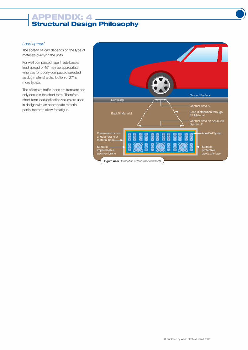
Load spread
The spread of load depends on the type ofmaterials overlying the units.
For well compacted type 1 sub-base aload spread of 45˚ may be appropriatewhereas for poorly compacted selected as dug material a distribution of 27˚ is more typical.
The effects of traffic loads are transient andonly occur in the short term. Thereforeshort-term load/deflection values are usedin design with an appropriate materialpartial factor to allow for fatigue.
Surfacing
Ground Surface
Contact Area A
Load distribution throughFill Material
Contact Area on AquaCellSystem A'
Backfill Material
Coarse sand or non angular granular material base
AquaCell System
Suitable impermeable geomembrane
Suitable protective geotextile layer
Figure A4.5 Distribution of loads below wheels
© Published by Wavin Plastics Limited 2002

Shall comprise modular geocellular boxstructures designed specifically for thepurpose of subterranean structural storageand distribution of water.
Installation of Geocellular Tank System
The geocellular units shall be installedstrictly in accordance with themanufacturer’s recommendations and in amanner that will not cause damage.
The constructed tank shall be surroundedwith a robust welded impermeablemembrane, overlaid with a heavy-dutygeotextile protection fleece prior to carefullybackfilling with selected granular material tothe approval of the Engineer.
© Published by Wavin Plastics Limited 2002
Element Value Unit
Nominal Unit Dimensions 1000 x 500 x 400 mm
Nominal Unit Volume 0.2 m3
Nominal Storage Volume 0.19 m3
Porosity (Void Ratio) 95 %
Ultimate Compressive Strength at Yield
– Vertical Loading on Top Face 560 kN/m2
– Lateral Loading on Side Face 77.5 kN/m2
Short Term Deflection– Vertical Loading On Side Face 1 per 97 mm per kN/m2
(applied load)– Lateral Loading On Side Face 1 per 7 mm per kN/m2
(applied load)
Estimated Long Term Deflection 0.4705 Ln (time in hours)(at up to 10 years at 20 ˚C at 10kN load)
Typical Physical Properties of the Geocellular Units shall be:
5A Element: AquaCell Attenuation System
Type: Pre-formed Geocellular Tank System
5B Element: AquaCell Infiltration System
Type: Pre-formed Geocellular Tank System
Shall comprise modular geocellular boxstructures designed specifically for thepurpose of subterranean catchment andsoakaway of water.
Installation of Geocellular Tank System
The geocellular units shall be installedstrictly in accordance with themanufacturer’s recommendations and in amanner that will not cause damage.
The constructed tank shall be surroundedwith a permeable geotextile prior tocarefully backfilling with selected granularmaterial to the approval of the Engineer.
APPENDIX: 5Specification

Installation of Domestic AttenuationSystem Control Chamber
The control chamber shall be installedstrictly in accordance with themanufacturer’s recommendations and in amanner that will not cause damage.
1m deep domestic attenuation systemcontrol chamber would use a sealed, squarecover and frame, suitable for use with foottraffic only with a 450mm opening size foruse to depths up to 1.2m (e.g. 6D935Polypropylene cover and frame). Whensurrounded by a concrete plinth can beused in situations with loading up to 35kN(3.5 Tonnes), i.e. domestic driveways.
1.25m deep domestic attenuation systemcontrol chamber would use a sealed,square cover and frame, suitable for usewith foot traffic only with a 350mm openingsize for use at depths greater than 1.2m.(e.g. 6D939 Polypropylene cover andframe). When surrounded by a concreteplinth can be used in situations with loadingup to 35kN (3.5 Tonnes), i.e. domesticdriveways.
Note: If the 1.25m deep chamber is cut tosize to accomodate 0.5m or 0.6m depth ofcover AquaCell situations, a 450mmopening size cover and frame should beused (6D935).
Element Value Unit
Nominal Unit Size for garage void storage 1000 x 500 mm deep x mm diameter
Nominal Unit Size for AquaCell storage 1250 x 500 mm deep x mm diameter
2 Incoming Connections 100 mm diameter
1 Outgoing Connection 100 mm diameter
1 Connection to Storage Facility 150 mm diameter
Discharge Rate at 150mm head 0.8 litres/sec
Discharge Rate at 225mm head 1 litres/sec
Discharge Rate at 300mm head 1.16 litres/sec
Discharge Rate at 400mm head 1.4 litres/sec
Storage Depth created for garage void type 300 mm
Storage Depth created for AquaCell type 400 mm
Typical Physical Properties of the domestic attenuation system control chamber shall be:
5C Element: Garastor Domestic Attenuation System Control Chamber
APPENDIX: 5Specification
© Published by Wavin Plastics Limited 2002

A single layer loose laid geomembrane suitablefor environmental protection to undergroundstructures, containments and cut-off trenches.
Polypropylene combines excellent chemical resistance with low flexuralmodulus to provide a malleable, flexiblemembrane suitable for non-smoothsurfaces and factory prefabrication tooptimise on site installation.
Application temperature of the geomembraneshall be greater than 4°C.
Number of layers: One ( 1 )
Laps – minimum 50mm
Jointing: Shall be formed using fusion (twinwedge) or extrusion bead welding inaccordance with manufacturer’srecommendations.
Workmanship Generally
Prelaying checks: Surface acceptability.Before laying check that substrate surfaces are:a) Structurally sound.b) Free from ridges and undulations.c ) Surface dry.d) Cleaned of loose and extraneous
material.
Construction Acceptability
Before laying check that construction allowsgeomembrane continuity to be maintained.
Laying Geomembrane
The Geomembrane is to be installed byqualified operatives recommended by thegeomembrane manufacturer andprefabricated into panels where appropriateto suit site requirements.
Laid strictly in accordance withmaufacturers recommendations.
When temperature is 4°C and falling, a hot air pre-heat system of welding should be adopted.
© Published by Wavin Plastics Limited 2002
Property Test Method
Thickness mm +/- 10% 1.0 ASTM D-751
Density g/cm3 Min 0.9 ASTM D-792
Tensile Stress @ Break Min N/mm2 18 ASTM D-638
Elongation @ Break % >700 ASTM D-638
Puncture Resistance Min N 150 FTMS 101C
Method 2065
Tear Resistance Min N 60 ASTM D-1004
Dimensional Stability +/- 2.0 ASTM D-1204
% Change Max 1 Hr @ 100˚C
Stress Crack Resistance 100% ASTM 5397
Volatile Loss 5% 0.2 ASTM D-1203
Loss Max Method A
Ozone Resistance No Cracks ASTM D-1149
Carbon Black Content 2– 3% ASTM 1603
Moisture Vapour g/m2/day < 0.1 ASTM E96
Friction Angle 21˚ Shear Box
(Non Woven Geotextile)
Methane Permeability 0.11 g/m2/day/atm European Standard
Methane Transmission Rate 0.8 x 10⁻⁹m
3/m
2/s/atm BRE
Permeability Coefficient 1.8 x 10⁻¹²
Protection Generally
Protect the finished insulation adequatelyto prevent damage during following works.
Cover the geomembrane with permanentoverlying construction as soon as possible.
Immediately prior to covering check fordamage and repair as necessary.
5D Element: Waterproof Geomembrane
Type: Polypropylene
APPENDIX: 5Specification

Pre-installation notes:
z Attenuation systems: connect the inflow and outflow pipework level with the base of the AquaCell structure
z Infiltration systems: connect the inflow pipework into the top of the AquaCell structure.
Order of Works:
1 Excavate hole or trench to requireddepth, dimensions and levels. Ensurethat the plan area is sufficient to allowcompaction plant access around sidesto compact backfill material (300mmminimum). Ensure base is smooth andlevel with no sharp drops or humps.Check slopes are cut to a safe angle oradequately supported and that safeaccess is provided to allow personnelto enter excavation.
2 Inspect base and ensure there are nosoft spots in the formation. If any softspots are present excavate out andreplace with compacted granular fillmaterial.
3 Lay 100mm coarse sand bedding layerto base of excavation and level. Laygeotextile protection fleece if requiredfor geomembrane (i.e. attenuation).
4 Lay geomembrane (or geotextile ifinfiltration) over sand bedding layer andup the sides of the excavation. Inspectgeomembrane for damage and test allwelds as required.
5 Install the AquaCell units in accordancewith installation schedule for correct
orientation, i.e. parallel with each otheror “brick bond” as required, whereverpossible, continuous vertical jointsshould be avoided. Arrange units sothat pre-formed sockets are in correctalignment for inlet and outlet pipes. Forsingle layer applications use the Wavinclips and for multi layers use Wavinclips and shear connectors.
6 Complete geotextile or geomembraneencapsulation to base, sides and top ofinstallation, including protection fleecewhere required. Geomembrane shouldbe welded with double seams. Inspectgeomembrane for damage and test allwelds as required.
7 Make drainage connections toinstallation utilising proprietaryadaptors. Ensure pre-formed socketpositions for pipe connections arelocated at correct position for receivingpipework. Alternatively use flangeadaptors attached to AquaCell unitswith adhesive tape and self tappingscrews (note flange adaptors cannotbe used at invert of AquaCell units intothe pre-formed socket). It isrecommended that all connections andair vent installations in attenuationapplications are made using a flangeadaptor, using adhesive or doublesided tape to form a seal. Alternativelyseal drainage connections into a pre-formed socket using proprietary sealsapproved by the geomembranemanufacturer.
8 Backfill around installation with Type 1or 2 sub base or Class 6P (side fill only)selected granular material inaccordance with the Specification forHighway Works. Compact in 150mmlayers.
9 Place coarse sand protection layer ifrequired over top of units. Continue tobackfill excavation with:
z Trafficked areas (car parks etc): Type1 or 2 sub base material compactedin 150mm layers in accordance withSpecification for Highway Works.Compaction plant over top ofsystem not to exceed 2300kg permetre width
z Landscaped and non-trafficked areas:selected as-dug material with size ofpieces less than 75mm compactedto 90% maximum dry density.Compaction plant over top of systemnot to exceed 2300kg per metrewidth.
10 Complete pavement construction orlandscaping over the AquaCell system.
APPENDIX: 6 Installation of AquaCell Stormwater Management system
© Published by Wavin Plastics Limited 2002

APPENDIX: 6 Installation of Garastor Control Chamber
Installation of Garastor inconjunction with theundercroft/void of a garage
Notes:
When using Garastor with theundercroft/void of a garage, it is theresponsibility of the designer to ensure thatthe enhancement to the garageundercroft/void and drainage workscomply with current prevailing BuildingRegulations.
Also to prevent softening of the soils belowthe foundations or loss of fines leading tosettlement, the void beneath the garageshould be lined as follows:
z Underneath the concrete base of thevoid area there should be a 1200gpolythene damp proof membrane
z Bitumastic paint should be appliedto the walls of the void area and tothe underside of the reinforcedgarage floor beams.
Fig. A6.1 shows a typical garastorinstallation using garage void.
Order of Works:
1 Place the Garastor unit (6SC500) on aminimum of 100mm ‘as-dug’ orgranular material. Ensure that the unit isas close to the garage undercroft/voidas possible and in a suitable position toallow pipework connection.
Note: it is important to ensure thatthe Garastor unit is placed in alevel position and that the invert ofthe 150mm pipe connection is levelwith the base of the concreteundercroft/void.
2 Connect the relevant pipework inaccordance with standard pipeinstallation guidelines.
3 Surround the Garastor unit with150mm of material similar to that usedfor the bedding.
4 Fit a 6D935 cover and frame (from theOsmaDrain range) to the top of theGarastor unit.
Fig. A6.1 Garastor: Typical system (garage void)
Typical Garastor installation using garage void*
Bitumastic paintapplied to walls ofvoid area andunderside of thegarage floor
6D935 cover andframe
Wall to retainstorage area
Stored water
Note: when surrounded by aconcrete plinth (150mm x 150mm)the cover can be used in situationswith a loading up to 35kN (3.5Tonnes) i.e. domestic driveways.
5 Adequate ventilation must be providedto the undercroft/void area using eitherair bricks or rainwater downpipesconnected directly into the storagearea.
75mm thicknessof smooth finishedconcrete
1200g polythenedamp proofmembrane
50mm sandlayer
Rainwater pipe(or air brick) forventilation
*Note: The depth of foundations forstandard block and beam garagefloors will need to be lowered byapprox. 300mm to accommodatethe storage capacity required.
150mm outflow pipework toundercroft/void
110mm inflow
pipework to
chamber
110mm outflow
pipework to
drainage system
© Published by Wavin Plastics Limited 2002

APPENDIX: 6 Installation of Garastor Control Chamber
Installation of Garastor inconjunction with AquaCell units
Notes:
When using Garastor in conjunction withAquaCell units, reference should be madeto relevant AquaCell installation details.
The Garastor unit is designed to coverinstallation depths up to 1.25m deep. Insituations where AquaCell cover is 0.5m or0.6m, cut chamber of unit to suit.
1 Place the garastor unit (6SC501) on aminimum of 100mm ‘as-dug’ orgranular material. Ensure that the unit isas close to the AquaCell structure aspossible and in a suitable position toallow pipework connection.
Note: it is important to ensure thatthe chamber is placed in a levelposition and that the invert of the150mm pipe connection is levelwith the base of the AquaCell units.
2 Connect pipework in accordance withstandard pipe installation guidelines.
3 Surround the Garastor unit with150mm of similar material to that usedfor the bedding.
4 For installations up to and including1.2m deep fit a 6D935 cover andframe (from the OsmaDrain range) tothe Garastor unit. Alternatively forinstallations deeper than 1.2m fit a6D939 cover and frame.
Note: when surrounded by aconcrete plinth (150mm x 150mm)the cover can be used in situationswith a loading of up to 35kN (3.5Tonnes) i.e. domestic driveways.
5 Adequate ventilation must be providedto the AquaCell structure using a WavinAir Vent. (NB. One air vent is requiredper 7,500 square metres ofimpermeable surface to be drained -see Fig.2.12, Section 2.3.6).
© Published by Wavin Plastics Limited 2002

Adsorption – The adherence of pollutantsor other substances to surfaces.
Aquifer – Layer of rock or soil that holds ortransmits water.
Asphalt – A mixture of mineral aggregatesand bitumen used in the construction ofroad and car park surfaces.
Attenuation – Slowing down the rate offlow to prevent flooding erosion, with aconsequent increase in the duration of flow.
Block paving – Pre-cast concrete or claybrick-sized flexible modular paving system.
Catchment area – The area contributingflow to a point on a drainage or riversystem.
Construction Quality Assurance (CQA) –A documented management systemdesigned to provide adequate confidencethat items or services:
z Meet contractual requirements
z Will perform adequately in service.
CQA usually includes inspection andtesting of installed components, andrecording the results.
Controlled Waters – Waters defined andprotected under the Water Resources Act1991, including inland freshwaters (relevantlakes and ponds, rivers and otherwatercourses), groundwater and coastalwaters.
For the full definition refer to the WaterResources Act 1991.
Creep – Long term deformation whichcontinues under a constant load.
Geomembrane – An impermeable plasticsheet, typically manufactured frompolypropylene, high density polyethylene orother geosynthetic material.
Geotextile – A plastic fabric which ispermeable.
Groundwater Protection Zone (SourceProtection Zone) – Areas around publicwater supply boreholes where groundwatermust be protected from pollution.
These are defined by reference to traveltimes of pollutants within the groundwater.
For specific details, see the EnvironmentAgency’s Policy and Practice for theProtection of Groundwater.
Hydrocarbons – Contaminants derivedfrom petrol, diesel and oil.
Impermeable – Will not allow water topass through it.
Infiltration – The passage of water througha surface into the underlying ground.
Permeability – A measure of the ease with which a fluid can flow through aporous medium.
This depends on the physical properties ofthe medium (e.g. grain size, porosity andpore shape).
Return period - How often an eventoccurs.
APPENDIX: 7Glossary of terms
z A 100-year storm refers to a stormevent that occurs, on average, onceevery hundred years. In other terms,the annual likelihood of repetition is1% (1/100).
z A 500-year storm is the storm eventexpected to occur only once every500 years. In this case, the annuallikelihood of repetition is 0.2%(1/500).
EXAMPLES
© Published by Wavin Plastics Limited 2002
Run-off – Water flow over the groundsurface to the drainage system. Thisoccurs if the ground is impermeable or issaturated.
Soakaway – A sub-surface structure intowhich water is conveyed to allow infiltrationinto the ground.
Source control – The control of run-off at,or near, its source.
Sub-base – The layer of aggregate laid onthe soil (or capping layer) to provide astable foundation for construction of theroad pavement.
SuDS – Sustainable Drainage Systems: asequence of management practices andcontrol structures designed to drainsurface water in a more sustainable fashionthan some conventional techniques.
Type 1 sub-base – Specification for themost commonly used sub-base material inconventional pavements – as prescribed bythe Specification for Highway Works.

i Department of the Environment,Transport and Regions (2000).Building a better quality of life: astrategy for sustainable developmentin the United Kingdom.
ii Department for Transport, Local Government and theRegions (2001).Planning Policy Guidance, Note 25:Development and Flood Risk. DTLR.
iii Environment Agency (1998).Policy and practice for the protectionof groundwater. The Stationery Office.
iv British Standards Institution (1973).British Standard Code of practice forplastics pipework (thermoplasticsmaterial). General principles and choiceof material. CP 312: Part 1: 1973.
v HR Wallingford (1981).Design and analysis of urban stormdrainage: The Wallingford Procedure,Volume 1: Principles, methods andpractice. National Water Council andDepartment of the Environment, 1981.
vi British Standards Institute (2000).Gravity drainage systems insidebuildings - Part 3: Roof drainage, layoutand calculation. BS EN12056-3:2000.
vii Building Research Establishment (1991).BRE Digest 365, Soakaway Design.
viii Construction Industry Researchand Information Association (1995).CIRIA Project Report 21 Infiltrationdrainage – Literature review.December 1995.
ix Construction Industry Researchand Information Association (1996).CIRIA Report 156 Infiltration drainage– Manual of good practice.
x R A Jewell (1996).Soil reinforcement with geotextiles.CIRIA Special Publication 123,Construction Industry Research andInformation Association, 1996.
xi Highways Agency, ScottishExecutive, National Assembly for Wales and Department forRegional Development Northern Ireland, 1998.Manual of contract documents forhighway works. Vol. 1: Specificationfor highway works.Stationery Office, London.
xii Construction Industry Researchand Information Association (1996).CIRIA Special Publication 124,Barriers, liners and cover systems for containment and control of land contamination.
xiii The American Society for Testingand Materials (2000).Standard test method for compressiveproperties of rigid cellular plastics.ASTM D1621-00.
xiv R A Jewell (1996).Soil reinforcement with geotextiles.CIRIA Special Publication 123,Construction Industry Research andInformation Association, 1996.
xv British Standards Institution (1995).British Standard BS8006:1995, Codeof practice for strengthened/reinforcedsoils and other fills. BSI.
xvi Ingold, T S (1994).Geotextiles and geomembranesmanual. First Edition. ElsevierAdvanced Technology.
xvii OC Young and M P O’Reilly (1983).A guide to design loadings for buriedrigid pipes. Transport and RoadResearch Laboratory, HMSO 1983.
xviii British Standards Institution (1997).British Standard BS8110, Part 1:1997, Structural use of concrete:Code of practice for design andconstruction. BSI.
xix British Standards Institution (1996).British Standard Loadings forBuildings. Part 1, Code of Practice for dead and imposed loads.BS 6399: Part1: 1996.
xx Rankine W J M (1857).On the stability of loose earth.Phil. Trans. Royal Society, 147.
APPENDIX: 8References
© Published by Wavin Plastics Limited 2002
Further Sources of Information:
z CIRIA Report 521 (2000).
Sustainable urban drainage systemsdesign manual for Scotland and NorthernIreland.
z CIRIA Report 522 (2000).
Sustainable urban drainage systemsdesign manual for England and Wales.
z CIRIA Report 523 (2001).
Sustainable urban drainage systems forbest practice manual for England,Scotland, Wales and Northern Ireland.