Embed Size (px)
Citation preview
AA/5/C
Appendices to the Proof of Evidence of
ANTHONY PARSONS BA, COSTAIN LIMITED
The United Utilities Water Limited (Eccles Wastewater Treatment Works)
Compulsory Purchase Order 2016
Appendix 1: Glossary
1
Appendix 1 – Glossary of terms and abbreviations
Bentonite slurry – A mixture of bentonite (a dried and pulverised clay powder) and water to
form a slurry of variable viscosity capable of carrying solid particles in suspension.
Bulkhead and air lock system – An installation in the tunnel to enable the section of tunnel
between the face and the bulkhead to be pressurised with air to balance the external water
and ground pressures and to permit access for personnel between the pressurised zone and
the atmospheric zone.
Closed face tunnel boring machine – A TBM operating with a closed front chamber
capable of withstanding soil and groundwater pressure and hence preventing ingress
disrupting the tunnelling process.
Compressible EPDM gaskets – A continuous gasket strip fitted in a retaining groove
around the full extent of the joint surfaces of each segment of the tunnel lining ring. The
gasket is manufactured from EPDM (Ethylene propylene diene monomer), a type of
synthetic rubber with a good track record in high pressure sealing in the water industry.
Depth of cover – Depth from ground surface to the top of a pipe, tunnel or other
underground structure.
EPB – Earth Pressure Balance
Expanding grout bag seal – A system for sealing a variable gap between two structures by
pumping grout into a purpose made bag or tube. The empty bag or tube is placed between
the structures and inflated to fill the gap. The bag or tube is normally fabricated from a strong
material with a weave that permits the passage of excess water but not the grout particles.
Face isolation doors – Hydraulically operated sliding doors fitted to the muck entry
openings in a TBM cutting wheel to support the ground and reduce water ingress when the
TBM is not excavating
Formation Level – The level of the underside of a structure or foundation
Full face rotating bi-directional cutting wheel – The rotating wheel on the front of a TBM
which carries the cutting tools and cuts a hole slightly larger than the TBM body. In soft
ground TBMs, the wheel is capable of turning in both directions to enable the control of TBM
roll.
Glacio Fluvial Clay – Clay formed by the action of glaciers moving over the land and
deposited in position as the glaciers receded.
Glacio Fluvial Sand and Gravel – Sands and gravels deposited by running water as the
glaciers melted and eroded the glacial clays and other strata
Grout – A liquid cementitious material injected between the excavated surface of the ground
and the outside of the tunnel lining which rapidly solidifies to support the ground and the
tunnel lining.
Head intervention – The activity of access by personnel into the normally closed chamber
at the front of an EPB or Slurry TBM.
Jacking Pipes – High strength thick walled pipes with uniform external diameter for use in
pipejacked tunnels.
2
Mixed Face – A tunnel face with two or more strata of differing soil types.
Nominal diameter – The required diameter of a pipe, tunnel or shaft which can tolerate
minor deviation.
Non cohesive water bearing soils – Soils which separate into discrete particles when
disturbed such as sands and gravels and which contain ground water below the water table.
Such soils can run uncontrollably when exposed.
Open belt TBM – A TBM operating without a closed front chamber where excavated
material is removed by a belt conveyor.
Pipejacking – A method of constructing an underground pipeline or tunnel using a TBM at
the head of a string of jacking pipes thrust forward by powerful jacks from the tunnel drive
shaft.
Portal – A reinforced concrete structure normally constructed on the inside face of a shaft to
facilitate the exit or entry of a tunnel. The portal provides structural stability to the shaft when
its lining is removed by the tunnelling process. The portal would normally have a circular
opening slightly larger than the tunnel external diameter in which sliding seal arrangements
could be installed to permit safe passage of the TBM in adverse ground conditions.
Precast concrete smoothbore bolted segmental tunnel lining rings – A common system
of structural tunnel support comprising concrete segments which bolt together to form a
lining with a smooth internal surface except for the joints and bolt pockets which can be
pointed to provide a uniform finish.
Rubber seals – A series of fixed rubber gaskets that provide a close sliding fit to the outside
of a TBM allowing it to move out of a shaft into water bearing ground without significant
ingress of groundwater around the TBM perimeter.
Screw Conveyor – A device to convey solids by rotating a continuous screw auger within a
tube. The auger is driven by a variable speed hydraulic motor so that the rate of soil removal
can be matched with the advance rate of the TBM in order to maintain the required pressure
in the closed chamber of an Earth Pressure Balance TBM.
Secant piled circular cofferdam – A system of pre-installed ground support comprising a
ring of bored concrete piles. The ring consists of alternating ‘soft’ and ‘hard’ piles. The ‘soft’
piles, without reinforcement, are installed first and then the ‘hard’ piles, with reinforcement ,
are installed, interlocking with the ‘soft’ piles to form a stiff cylinder capable of excluding
groundwater and carrying significant hoop forces from ground loading.
Segmental tunnel linings – Tunnel lining comprising precast units which join together to
form a cylindrical structure.
Soft zones – Pre-determined areas in the wall of a shaft or cofferdam to allow the TBM to
mine through without difficulty. This normally involves the use of glass fibre reinforcing bars
in the concrete in lieu of steel.
TBM – Tunnel Boring Machine – A mechanised type of tunnelling shield providing protection
to the workforce against ground collapse, mechanised excavation and spoil removal and
mechanised handling and installation of the tunnel lining.
TBM tail shield – The rear part of a TBM, fitted with trailing wire brush seals, where the
segmental tunnel lining is installed after each excavation advance.
3
Trailing steel wire brush seals – A series of wire brush units fitted within the rear of the
TBM tail shield to form a continuous ring to bear on the outside of the tunnel lining as it
leaves the tail shield as the TBM advances. In order to prevent to intrusion of groundwater
and grout, the brushes are continuously replenished with bio-degradable water proof grease
under pressure.
Tremied base plug – A mass concrete base to a shaft formed under water by placing
concrete through a ‘tremie’ pipe from the surface. The bottom of the pipe is maintained
within the body of the wet concrete throughout the pour to prevent mixing of the concrete
with the water.
Trough width coefficient – An empirically derived number used in the calculation of
predicted ground settlement due to tunnels and shafts. The value of the coefficient varies for
different ground conditions.
Tunnel invert – The lowest point on the internal bore of a pipe or tunnel.
Underpinning – A method of shaft sinking using circular precast linings fitted beneath the
previously installed lining ring as excavation proceeds. Each lining ring is grouted into
position before the next ring can be placed. The method relies on stable ground and the
general absence of groundwater.
Weathered – A description of a soil or rock mass that has been affected by surface
atmospheric conditions, mainly in the distant past, such as heat, cold, moisture and
oxygenation. Weathering commonly results in a loss of soil structure and strength compared
with unweathered strata.
Wet caisson – A method of shaft sinking commonly used in water bearing soft ground
where excavation can be carried out under water using a grab type excavator. The shaft
lining ring is fitted with a circular cutting shoe having a slightly larger diameter than the lining.
Further lining rings are fitted at the top of the lining structure as excavation proceeds. The
space between the ground and the lining is filled with a lubricating slurry to support the
ground and to minimise friction. The force to sink the caisson is a combination of dead
weight and a series of hydraulic jacks mounted vertically above the lining rings and fitted to a
heavy collar ring. On completion of caisson sinking, the base is plugged by a tremied base
plug.
AA/5/C- Appendices to Proof of Evidence
Appendices to the Proof of Evidence of
ANTHONY PARSONS BA, COSTAIN LIMITED
The United Utilities Water Limited (Eccles Wastewater Treatment Works)
Compulsory Purchase Order 2016
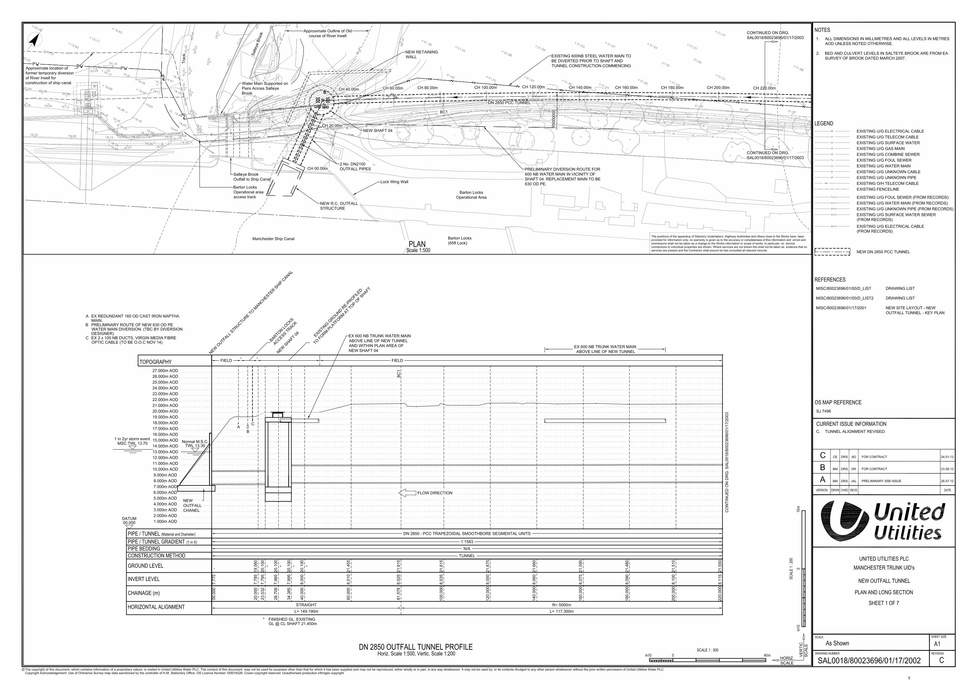
Appendix 2.1: Previous Scheme Plan – Drawing No SAL0018/80023696/01/17/2002 C
4
5
Reference 1
AA/5/C
Appendices to the Proof of Evidence of
ANTHONY PARSONS BA, COSTAIN LIMITED
The United Utilities Water Limited (Eccles Wastewater Treatment Works)
Compulsory Purchase Order 2016
Appendix 2.2: List of Previous EPB Projects
6
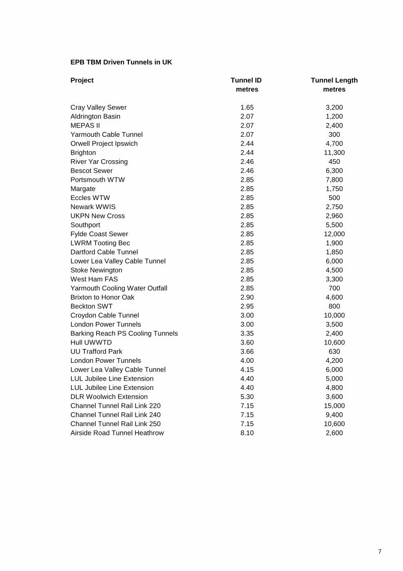
EPB TBM Driven Tunnels in UK
Project Tunnel ID Tunnel Length
metres metres
Cray Valley Sewer 1.65 3,200
Aldrington Basin 2.07 1,200
MEPAS II 2.07 2,400
Yarmouth Cable Tunnel 2.07 300
Orwell Project Ipswich 2.44 4,700
Brighton 2.44 11,300
River Yar Crossing 2.46 450
Bescot Sewer 2.46 6,300
Portsmouth WTW 2.85 7,800
Margate 2.85 1,750
Eccles WTW 2.85 500
Newark WWIS 2.85 2,750
UKPN New Cross 2.85 2,960
Southport 2.85 5,500
Fylde Coast Sewer 2.85 12,000
LWRM Tooting Bec 2.85 1,900
Dartford Cable Tunnel 2.85 1,850
Lower Lea Valley Cable Tunnel 2.85 6,000
Stoke Newington 2.85 4,500
West Ham FAS 2.85 3,300
Yarmouth Cooling Water Outfall 2.85 700
Brixton to Honor Oak 2.90 4,600
Beckton SWT 2.95 800
Croydon Cable Tunnel 3.00 10,000
London Power Tunnels 3.00 3,500
Barking Reach PS Cooling Tunnels 3.35 2,400
Hull UWWTD 3.60 10,600
UU Trafford Park 3.66 630
London Power Tunnels 4.00 4,200
Lower Lea Valley Cable Tunnel 4.15 6,000
LUL Jubilee Line Extension 4.40 5,000
LUL Jubilee Line Extension 4.40 4,800
DLR Woolwich Extension 5.30 3,600
Channel Tunnel Rail Link 220 7.15 15,000
Channel Tunnel Rail Link 240 7.15 9,400
Channel Tunnel Rail Link 250 7.15 10,600
Airside Road Tunnel Heathrow 8.10 2,600
7
AA/5/C
Appendices to the Proof of Evidence of
ANTHONY PARSONS BA, COSTAIN LIMITED
The United Utilities Water Limited (Eccles Wastewater Treatment Works)
Compulsory Purchase Order 2016
Appendix 2.3: Outline Method Statement
8
United Utilities Methodology
Manchester Trunk UIDs – SAL 0018 – Eccles WWTW Page 1 of 8
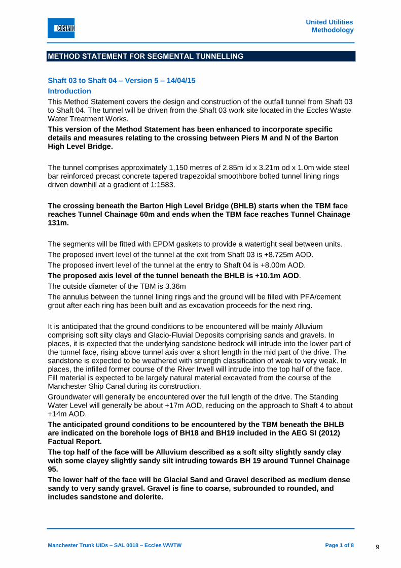
METHOD STATEMENT FOR SEGMENTAL TUNNELLING
Shaft 03 to Shaft 04 – Version 5 – 14/04/15
Introduction
This Method Statement covers the design and construction of the outfall tunnel from Shaft 03 to Shaft 04. The tunnel will be driven from the Shaft 03 work site located in the Eccles Waste Water Treatment Works.
This version of the Method Statement has been enhanced to incorporate specific details and measures relating to the crossing between Piers M and N of the Barton High Level Bridge.
The tunnel comprises approximately 1,150 metres of 2.85m id x 3.21m od x 1.0m wide steel bar reinforced precast concrete tapered trapezoidal smoothbore bolted tunnel lining rings driven downhill at a gradient of 1:1583.
The crossing beneath the Barton High Level Bridge (BHLB) starts when the TBM face reaches Tunnel Chainage 60m and ends when the TBM face reaches Tunnel Chainage 131m.
The segments will be fitted with EPDM gaskets to provide a watertight seal between units.
The proposed invert level of the tunnel at the exit from Shaft 03 is +8.725m AOD.
The proposed invert level of the tunnel at the entry to Shaft 04 is +8.00m AOD.
The proposed axis level of the tunnel beneath the BHLB is +10.1m AOD.
The outside diameter of the TBM is 3.36m
The annulus between the tunnel lining rings and the ground will be filled with PFA/cement grout after each ring has been built and as excavation proceeds for the next ring.
It is anticipated that the ground conditions to be encountered will be mainly Alluvium comprising soft silty clays and Glacio-Fluvial Deposits comprising sands and gravels. In places, it is expected that the underlying sandstone bedrock will intrude into the lower part of the tunnel face, rising above tunnel axis over a short length in the mid part of the drive. The sandstone is expected to be weathered with strength classification of weak to very weak. In places, the infilled former course of the River Irwell will intrude into the top half of the face. Fill material is expected to be largely natural material excavated from the course of the Manchester Ship Canal during its construction.
Groundwater will generally be encountered over the full length of the drive. The Standing Water Level will generally be about +17m AOD, reducing on the approach to Shaft 4 to about +14m AOD.
The anticipated ground conditions to be encountered by the TBM beneath the BHLB are indicated on the borehole logs of BH18 and BH19 included in the AEG SI (2012) Factual Report.
The top half of the face will be Alluvium described as a soft silty slightly sandy clay with some clayey slightly sandy silt intruding towards BH 19 around Tunnel Chainage 95.
The lower half of the face will be Glacial Sand and Gravel described as medium dense sandy to very sandy gravel. Gravel is fine to coarse, subrounded to rounded, and includes sandstone and dolerite.
9
United Utilities Methodology
Page 2 of 8 Manchester Trunk UIDs – SAL 0018 – Eccles WWTW
Groundwater was struck in both boreholes at the clay/gravel interface. The gravel is expected to be water bearing and have significant permeability. The standing water level in the gravel is expected to be at about +17m AOD.
Details of the proposed tunnel lining ring are shown on Buchan Drawing No D_C304 Rev C1.
The alignment details of the proposed tunnel are shown on UU Drawing No SAL0018/80023696/01/17/2006 Rev D.
Construction Proposals
It is proposed that the tunnel is constructed using a Lovat MP132SE TBM operating in earth pressure balance mode. This TBM forms part of the current Costain fleet and was purchased new in 2009 for a 3.3km long project in London for Thames Water. The TBM has recently been fully refurbished for the SAL 0018 Project. It will complete the tunnel drive from Shaft 03 to Shaft 02 before commencing the drive from Shaft 03 to Shaft 04.
The TBM consists of three sections being Forward Shell, Stationary Shell and Tail Shield.
The Forward Shell is equipped with a full face, hydraulically driven, bi-directional rotating, three spoke cutting wheel fitted with scrapers and ripper tools. This is suitable for excavating soft ground and weak rock. The six openings in the cutting wheel are fitted with hydraulically operated isolation doors which can be closed to completely prevent the ingress of soil and water into the plenum chamber. During excavation, material passes through the openings in the wheel into the plenum chamber, which is maintained in a full condition under pressure by balancing the removal of material with the screw conveyor with the advance of the TBM. Excavated material will be conditioned as necessary by the addition of foams or polymers injected through ports in the wheel spokes, plenum chamber and screw conveyor sleeve to achieve the fluidity and reduced permeability required to maintain a plug of excavated material in the screw. When not mining, the face can be isolated by closing the isolation doors on the cutting wheel and closing a guillotine door on the discharge end of the screw conveyor. Emergency accumulator systems are fitted to enable closure of all doors in the event of a failure of the power supply to the TBM.
The Forward Shell is connected to the Stationary Shell with four pairs of active hydraulic articulation cylinders arranged at 90 degree centres. Water tightness and articulation of the joint is provided by a spigot and socket arrangement fitted with a sliding rubber seal. The sealing system is designed to resist 3 bar of external water pressure.
The Stationary Shell contains the main electric motors, hydraulic pumps and hydraulic tank required to provide power to the TBM. The shell also contains the 12 hydraulic propulsion cylinders required to advance the TBM through the ground together with the TBM operator’s control station. The hydraulically operated rotary segment erector is mounted on a central slide table adjacent to the rear bulkhead of the Stationary Shell which cantilevers out into the Tail Shield around the body of the screw conveyor.
The Stationary Shell is rigidly connected to the Tail Shield with a bolted flange connection. Water tightness of the joint is again provided by a spigot and socket joint fitted with a sliding rubber seal. In the event that the joint needs to be articulated to negotiate a tight curve, the bolts can be loosened, the required joint angle set, the joint gap shimmed to suit and the bolts retightened. The rear of the Tail Shield is fitted with three rows of wire brush seals which bear on the outside of the built lining ring as it slides out of the back of the shield. The wire brushes are filled with waterproof grease which is regularly topped up and pressurised
10
United Utilities Methodology
Manchester Trunk UIDs – SAL 0018 – Eccles WWTW Page 3 of 8
through feed pipes set into the skin of the shield. The rear of the shield is also fitted with two rings of spring steel grout check plates which impede the flow of grout around the TBM and into the brush seals.
The TBM ancillary systems are mounted on a series of sledges and wheeled gantries towed by the TBM. The ancillary systems comprise high level belt conveyor, segment transport monorail, segment unloaders, grout injection system, ground conditioning system, railing up system, high voltage transformer, electrical distribution cabinets, high voltage cable reeler, auxiliary ventilation equipment, ventilation cassette lifting system, air compressor, gas monitoring system, fire detection and suppression system, communication system together with all necessary cables, pipes, ducts etc.
TBM alignment control is provided by a computerised laser guidance system.
Once fully established, the TBM is serviced by a tunnel railway system which delivers materials and removes excavated spoil. Each train has sufficient capacity for one ring (1 metre) advance of the tunnel and comprises two segment cars, one grout car, five muck cars, one personnel carrier and a 5.5T battery operated locomotive. The trains run on 610mm gauge track using curved steel sleepers fitting tightly to the invert of the tunnel lining in order to minimise trip hazards and maximise headroom.
The TBM is also serviced by fixed installations on the tunnel wall comprising 3.3KV cable, cooling water feed and return pipes, dirty water discharge pipe, communication cables and telemetry cables. A 600mm dia ventilation duct is suspended from the tunnel soffit.
Tunnel lighting is provided by 110V strip lights fixed to the tunnel wall at 10m centres supplied from 3.3KV/110V transformers at a maximum of 400m intervals along the HV supply cable. Battery operated emergency lights are installed at intervals to provide low level lighting in the event of main power failure.
Hop up refuges are provided at 50m intervals so that any pedestrians in the tunnel can allow trains to pass safely.
A raised twin track section of railway will be installed adjacent to the drive shaft to enable trains to pass each other and thus permit train preparation in the drive shaft to be carried out concurrently with TBM operation. A hydraulically operated traverser unit will be utilised in the pit bottom to enable rolling stock to be moved from one line to another.
The shaft will be serviced by an 80T hydraulic crawler crane lifting, tipping and lowering muck skips, lowering segments and temporary materials.
Muck skips will be tipped using a purpose designed tipping frame into a contained muck bay where any free water can be collected and treated for disposal. Drained spoil will be loaded by hydraulic excavator into tipper lorries for disposal off site.
Tunnel lining segments will be unloaded by heavy duty forklift or service crane and stored in an area adjacent to the shaft crane.
11
United Utilities Methodology
Page 4 of 8 Manchester Trunk UIDs – SAL 0018 – Eccles WWTW
Grout will be mixed by a dedicated plant with holding tanks to allow rapid filling of the grout cars in the pit bottom. Cement and PFA will be stored in 50T silos adjacent to the mixing plant.
Power for the TBM and tunnelling systems will be supplied from the local mains. A 350kVA generator will be maintained on site on a standby basis to provide power for essential functions in the event of mains power failure.
Operation of the TBM under the BHLB
The TBM will be operated in Earth Pressure Balance mode with the objective of reducing ground movements around the tunnelling process to a minimum which should limit the potential for movement of the BHLB support pier pile caps.
Piezometer readings indicate that the Standing Ground Water Level in the Glacial Sand and Gravel will be at +17.00m AOD. The Ground Water Head measured at the TBM axis level will therefore be approximately 7m, equivalent to a pressure of 0.7 bar. This represents the minimum EPB operating pressure required to prevent movement of ground water towards the TBM.
The general ground level beneath the BHLB is +17.75m AOD. The depth of ground cover to the TBM axis is therefore approximately 7.75m. Assuming an average soil density of 1.9T/m3, the average overburden pressure will be 14.7T/m2, equivalent to a pressure of 1.47 bar. This is considered to be the maximum allowable EPB operating pressure to prevent ground heave.
It is therefore proposed that the target EPB operating pressure should be 1.1 bar, with a lower bound of 0.8 bar and an upper bound of 1.4 bar, all as measured at TBM axis
The maintenance of the EPB pressure in the plenum chamber is achieved by the operator varying the rate of advance of the TBM in conjunction with varying the speed of the screw conveyor.
This directly controls the rate at which material enters and leaves the chamber.
Face pressure is measured by EPB sensors at three levels on the forward bulkhead. The read out from the sensors is directly displayed on the operator’s screen and is recorded continuously in the TBM data records.
The advance rate of the TBM will be set to match the optimum grouting system performance consistent with filling the annulus void effectively as the TBM advances.
The grouting system will be operated in a manner that enables grout to be injected simultaneously on both sides of the tunnel using independent grout pumps, with the objective of filling the annulus void as it is generated to prevent ground movement immediately behind the Tail Shield.
The grouting quantities will be monitored and recorded to check that interim flow rates are consistent with the TBM advance rate and that the total grout take for each TBM advance is in accordance with the theoretical volume.
12
United Utilities Methodology
Manchester Trunk UIDs – SAL 0018 – Eccles WWTW Page 5 of 8
Grouting pressure will need to be sufficient to overcome groundwater pressure (0.7 bar) but not high enough to overcome overburden pressure (1.4 bar).
Initial trialling of the system on the drive from Shaft 3 to Shaft 2 will enable grout system settings to be established.
Construction Sequence
Following completion of the tunnel drive to Shaft 02, the pit bottom installations, except for the staircase, will be stripped down and removed from the shaft.
A raised working deck will be installed in the shaft base to provide an initial working level of +7.975m AOD.
A temporary concrete thrust wall will be constructed bearing on the shaft wall diametrically opposite the tunnel centre line break out point.
A fabricated steel launch seal holding assembly will be fitted to the tunnel portal to seal the annulus as the TBM breaks out of the shaft and prevent the ingress of groundwater and fine soils until the first few tunnel lining rings are established and grouted through the portal.
A fabricated steel TBM launch cradle will be installed in the shaft to suit the design tunnel alignment. The first two sections of the TBM will be lowered on to the cradle and the screw conveyor installed in short mode for launch.
A temporary thrust assembly will be installed between the TBM and the thrust wall and the TBM will be advanced through the seals up to the secant pile shaft wall. The temporary thrust assembly will be extended and an anti-rotation assembly will be fitted to prevent roll of the shield when excavation starts.
The Forward Shell plenum chamber and the portal annulus will be filled with a bentonite/sand mix to ensure the chamber is full on exit from the shaft.
The TBM will be advanced carefully through the shaft wall and into the ground, discharging excavated material through the screw conveyor into muck skips. When the rear of the Stationary Shell reaches the portal face, excavation will cease and the face isolation doors will be closed. Additional conditioning polymer will be injected into the chamber and screw conveyor to provide a reliable plug against water infiltration. A brake arrangement will be deployed to prevent the reversal of the TBM under groundwater pressure when the thrust rams are released.
The temporary thrust assembly will be removed, the screw conveyor will be extended to full length and the segment erector fitted to the slide table at the rear bulkhead of the Stationary Shell. The Tail Shield will be installed and the temporary thrust assembly will be reinstalled. The thrust assembly will incorporate minor modifications to enable full rings to be constructed in the Tail Shield as the TBM advances.
Excavation will recommence with rings built at one metre intervals until the lining can be grouted into the portal to seal the annulus. The segment transport and unloader sledges,
13
United Utilities Methodology
Page 6 of 8 Manchester Trunk UIDs – SAL 0018 – Eccles WWTW
together with Gantry 1, will be installed and coupled to the TBM. A short section of belt conveyor will be installed to discharge at the rear of Gantry 1.
Excavation and ring building will recommence with muck removal on a single or double skip basis until the TBM has advanced to Chainage 60 where the BHLB zone of influence starts. During this period, grout will be supplied by pipe directly from the surface. Back up gantries will be installed at intervals as the TBM advances and services will be provided by temporary umbilical lines until the permanent lines can be installed.
At Chainage 60, it is envisaged that sufficient gantries will have been installed such that the main HV transformer and electrical control cabinets will be in the tunnel enabling all main cabling and hydraulic systems to be tested and approved. The belt conveyor will also be installed and tested at full operational length.
Excavation and ring building will recommence on a single train basis until there is sufficient room behind the TBM to complete gantry installation and to install the pit bottom crossing at about Chainage 180.
Excavation from Chainage 60 to Chainage 131 will be carried out on a continuous 24 hour per day, 7 day per week basis.
The pit bottom thrust assembly, temporary half rings and launch cradle will be removed. The twin track crossing will be installed in the tunnel, the traverser unit installed in the pit bottom and the pit bottom decked out at crossing level for operational use.
Tunnel construction will recommence on a two train basis until about Chainage 700 when a further twin track crossing will be installed behind the TBM allowing three trains to be used.
Tunnelling will continue up to Shaft 04 where the TBM will mine through the secant piles into the reception portal and into a block of foam concrete surcharged with water to equalise the groundwater pressure. The whole of the TBM will be within the shaft allowing the lining rings immediately behind the TBM to be grouted into the portal thus excluding ground and groundwater when the TBM is exposed and removed.
The reception shaft will be pumped out and the foam concrete removed exposing the TBM. The TBM and back up equipment will be removed from the shaft and transported off site.
The tunnel services and railway system will be removed and the tunnel cleaned out.
Segment joints and bolt pockets will be pointed and any segment damage repaired leaving a smooth clean tunnel for handover.
. Equipment and Materials
▪ Lovat ME132SE TBM and back up
▪ 5.5T battery powered locomotives
▪ Segment cars
▪ Grout cars
▪ Tunnel muck skips
▪ Personnel carriers
14
United Utilities Methodology
Manchester Trunk UIDs – SAL 0018 – Eccles WWTW Page 7 of 8
▪ 610 gauge track
▪ 610 gauge twin track turn outs
▪ Traverser unit
▪ 3.3KV electric cable
▪ 100mm dia galvanised steel pipe
▪ 80T crawler crane
▪ Compressor 250cfm
▪ Grout mixing and pumping equipment
▪ 50T cement silos
▪ 7T fork lift
▪ Power generation equipment (standby)
▪ Electrical distribution cabin
▪ Fuel storage and distribution
▪ 2.85m id precast concrete segmental tunnel linings
▪ PFA/cement grout
▪ Waterproof grease
Interface with United Utilities Processes/Assets
There will be no direct interface with existing United Utilities Processes or Assets whilst carrying out the tunnelling works. The works will however be constructed from within an existing waste water treatment works requiring shared access facilities. Best endeavours will be employed to ensure access for UU operations is not impeded.
Interface with Third Party Assets
BHLB – The tunnel will pass between Piers M & N of the Barton High Level Bridge. The proposed works are the subject of a D/AIP approved by the Highways Agency and their technical advisors. The works will be carried out strictly in accordance with the provisions of the agreed D/AIP.
A comprehensive Instrumentation and Monitoring Plan will be implemented to confirm that ground and asset movements are within expectations. Details are set out in Appendix ?? of the D/AIP.
Particular Health, Safety and Environmental Issues
The following Health, Safety and Environmental issues will be addressed during the preparation of the technical and safety method statements and during the construction of the works. The construction phase HASEMP will contain general information regarding Health, Safety and Environmental concerns. These as well as detailed specifics will be contained within the activity method statements for the construction of the tunnelling works.
The following list is not intended to be exhaustive:
▪ Confined space working
▪ Tunnel railway system
▪ Monitoring of air quality – ventilation
15
United Utilities Methodology
Page 8 of 8 Manchester Trunk UIDs – SAL 0018 – Eccles WWTW
▪ All personnel to be made fully aware of the safety implications of working within a shaft
and tunnel environment
▪ Temporary works designs to be checked and signed off by Costain temporary works
engineers. All internally designed temporary works to be checked and signed off by an
independent engineer not directly involved in the project
▪ Lifting operations to be properly planned, monitored, certified and implemented
▪ All personnel to be fully qualified to perform their duties
▪ All equipment to be certified as required
▪ All personnel to receive adequate training where necessary
▪ All personnel to attend shift start safety briefing
▪ Permit to Work system to be operated where necessary
▪ Oil and fuel storage regime to be strictly controlled
▪ Appropriate discharge consents to be obtained for disposal of any surface or
groundwater
▪ Monitoring of compliance with waste disposal licence for spoil disposal
There are no significant environmental issues associated with the tunnelling works from Shaft 03.
Apart from the crossing of the BHLB, It is envisaged that the works will be carried out on a day and night shift basis, Monday to Friday, with weekends utilised for maintenance work only. There are no residential properties in close proximity to Shaft 03 and disturbance from night time working is not anticipated.
16
Reference 1
AA/5/C
Appendices to the Proof of Evidence of ANTHONY PARSONS BA, COSTAIN LIMITED
The United Utilities Water Limited (Eccles Wastewater Treatment Works)
Compulsory Purchase Order 2016
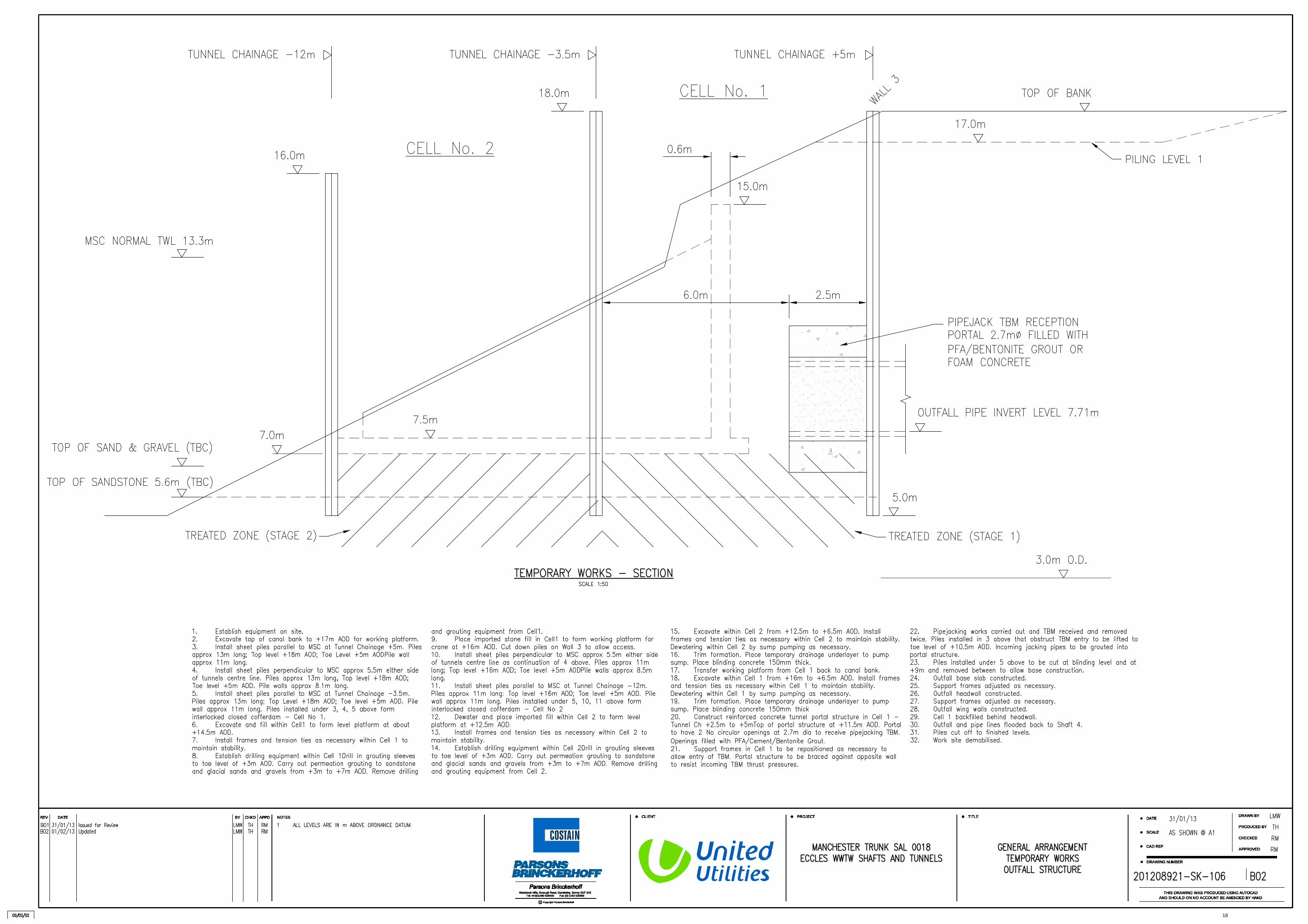
Appendix 2.4: General Arrangement – Temporary Works – Outfall Structure – Drawing No 201208921-SK-106 Rev B02 dated 31/01/2013
17
CHKDREV DATE BY APPD
C Copyright Parsons Brinckerhoff
Tel: 44-(0)1483 528400 Fax (0)-1483 528989Westbrook Mills, Borough Road, Godalming, Surrey GU7 2AZ
CLIENT PROJECT TITLE
PRODUCED BY
THIS DRAWING WAS PRODUCED USING AUTOCADAND SHOULD ON NO ACCOUNT BE AMENDED BY HAND
DRAWING NUMBER
CAD REF
SCALE
DATE
CHECKED
APPROVED
DRAWN BYNOTESCHKDREV DATE BY APPD
C Copyright Parsons Brinckerhoff
Tel: 44-(0)1483 528400 Fax (0)-1483 528989Westbrook Mills, Borough Road, Godalming, Surrey GU7 2AZ
CLIENT PROJECT TITLE
PRODUCED BY
THIS DRAWING WAS PRODUCED USING AUTOCADAND SHOULD ON NO ACCOUNT BE AMENDED BY HAND
DRAWING NUMBER
CAD REF
SCALE
DATE
CHECKED
APPROVED
DRAWN BYNOTES
18
Reference 1
AA/5/C
Appendices to the Proof of Evidence of ANTHONY PARSONS BA, COSTAIN LIMITED
The United Utilities Water Limited (Eccles Wastewater Treatment Works)
Compulsory Purchase Order 2016
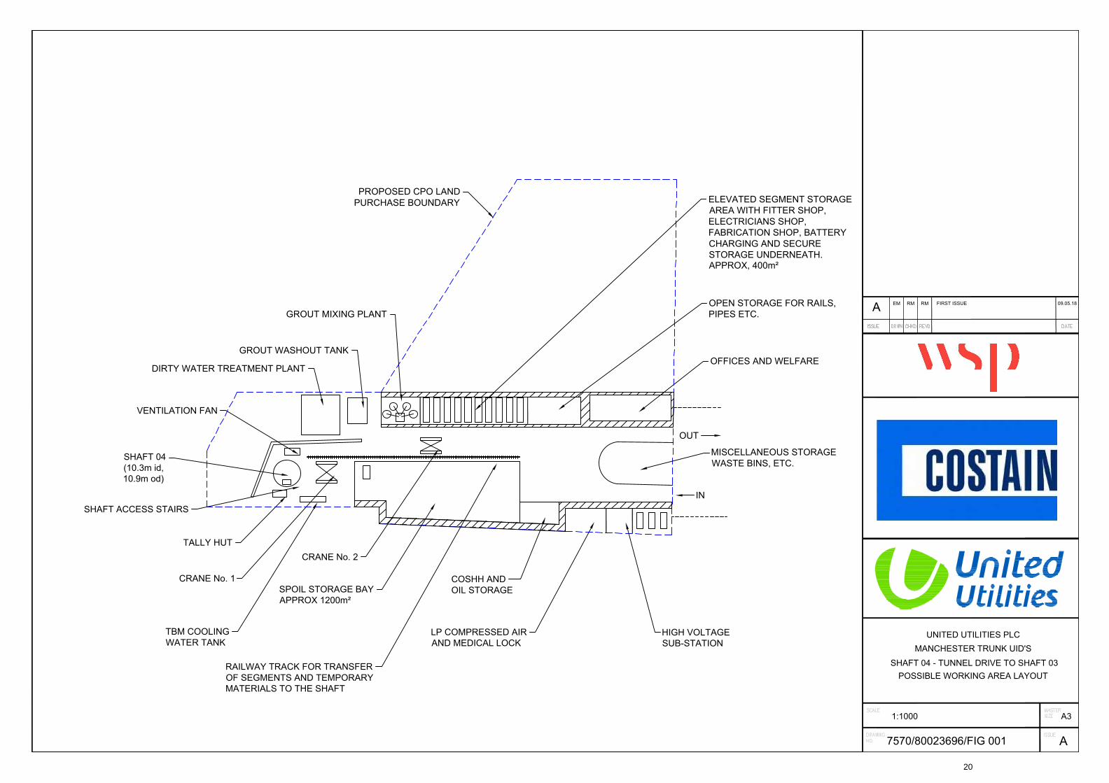
Appendix 2.5: Shaft 04 – Tunnel drive to Shaft 03 – Possible Working Area Layout –
Drawing No 7570/80023696/FIG 001 A
19
Joint VentureATKINSCOSTAINGALLIFORD TRY
UNITED UTILITIES PLC
MANCHESTER TRUNK UID'S
SHAFT 04 - TUNNEL DRIVE TO SHAFT 03
POSSIBLE WORKING AREA LAYOUT
1:1000 A3
7570/80023696/FIG 001A
09.05.18
A
FIRST ISSUERMEM RM
PROPOSED CPO LAND
PURCHASE BOUNDARY
ELEVATED SEGMENT STORAGE
AREA WITH FITTER SHOP,
ELECTRICIANS SHOP,
FABRICATION SHOP, BATTERY
CHARGING AND SECURE
STORAGE UNDERNEATH.
APPROX, 400m²
GROUT MIXING PLANT
OPEN STORAGE FOR RAILS,
PIPES ETC.
OFFICES AND WELFARE
OUT
IN
MISCELLANEOUS STORAGE
WASTE BINS, ETC.
GROUT WASHOUT TANK
DIRTY WATER TREATMENT PLANT
VENTILATION FAN
TALLY HUT
TBM COOLING
WATER TANK
CRANE No. 1
CRANE No. 2
SPOIL STORAGE BAY
APPROX 1200m²
LP COMPRESSED AIR
AND MEDICAL LOCK
COSHH AND
OIL STORAGE
HIGH VOLTAGE
SUB-STATION
RAILWAY TRACK FOR TRANSFER
OF SEGMENTS AND TEMPORARY
MATERIALS TO THE SHAFT
SHAFT ACCESS STAIRS
SHAFT 04
(10.3m id,
10.9m od)
20


![Neurology II 2.07 Pain Dr. Camara Chua[1]](https://img.pdfslide.us/doc/110x75/563dba07550346aa9aa2175a/neurology-ii-207-pain-dr-camara-chua1.jpg)