Embed Size (px)
Citation preview

/¸/
; Ij /I J
\j/
D._ASJIJ GR OR TMX OR AD NU MBfR_"
ICA'r F_GORIrt
I I
%_b
Z65o12t_
L.,._:
_|NASA-CR- 126236) APOLLO SYSTEMSENGINEERING NgNUAL: SE}IVICE I_ODULE AND
ADAPT_R ST_UCTUHE (North AmeEican Aviation,
Inc.) 19 Feb. 196_ 370 p
I
6O/99
N72-71709
Unclas
15610
7"65".12132 i
Accession No. 55566-64
Copy No.
APOLLO SYSTEMS ENGINEERINGService Module and
Adapter StructureJ.',
":_,._ CONTRACT NASg-150
19'_,February1964
SID 64-206(DIM-9)
MANUAL
Exhibit I, Paragraph 5.2
NORTH AMERICAN AVIATION, INC.SPACE and INFORMATION SYSTEMS DIVISION
• 7
,':" :4",., ', ;. .... '%
° i ':;,• %
- !,
LV_L_L[ _0 "AS_"_°QuA_TERs o.t_
NORTH AMERICAN AVIATION, INC. V°lume:DEM-9SPACE and INFORMATION SYSTEIV_ DIVISION Section:
Page: ii
Date: 2-19-64
Rev. Date:
FOREWORD
This manual is one in a series of special Apollo Engineering Manuals (Dli4'si through 18) which furnish a contemporary source of desigm and system in[orm,j-
tion_ and descriptions for the Apollo spacecraft. This manual_ DIM-9, contains
basic information, by use of text and i!lustrations_ on the components of the
service module and adapter structures.
Illustrations include: a. over-all configuration control drawings of' both
service module (S/M) and adapter; b. detail drawings of component parts;
c. installation drawings; d. interface control drawings_ when available.
The structural components of the service module and the adapter are designedto operate within desio_n limftations while subjected to environmental restric-
tions imposed by the NASA Exhibit "B" Technical Specification, Part I, dated3 January 1963.
A final manual can not be consummated at this time. Expanding, dynamic, and
involved technology of the subject matter permits the issuance only of pertinent
information on an as-known basis. When relevant data appear_ revisions will bein order.
The service module and adapter structures Manual Review Board is composed
of, but not limited to_ the following personnel:
Chairman: J.R. Cole, Chief 696-420
Service Module Design
Alternate: To be determined
Recorder: To be determined
Members: (Or their representatives)
H.S. Oder, Chief
Spacecraft Structural Analysis
696-230
J.W. Gibb, Chief
Propellant Systems
696-320
D.I. Champaign_ ChiefElectrical Power
697-810
R.E. Field, Chief
Propulsion Engines
696-310
M.E. Stelzriede, Chief
Environmental Control System
696-510
SID 64-206

I
NORTI-I AlVlERICAN AV'IATION, INC. Volume: DIM-9__
SPACE and INFORMATION SY_STEMS DIVISION S e cti on. --_
Page: iii
Date: ___
Rev. Date:
The following lead engineers can give more definite information on_ andanswers to_ technical questions in their areas of specialization:
H. W. Myers - Spacecraft LI_M Adapter
D. M. Robison - S/M Structure
E. G. Stecki - S-I Adapter; Mounting Provisions for S/M and Adapter
T. Bucuvalas - Service Propulsion System_ Main Tanks
K. C. Dullea - Mounting Provisions for Environmental Control and
Electrical Power Systems
B. F. Glienke - Mounting Provisions for Reaction Control System, Service
Propulsion and Pressurization Systems
Cole,Chie Apollo Service Module Design
SID 64-206
/NORTH AMERICAN AVIATION, INC.SPACE and INFORMATION SYSTEMS DIVISION
Volume= DIM- 9
Section:
Page: iv
Date: _-19-64
Rev. Date:
CONTENTS
Section
1.0
2.0
3.0
4.0
5.0
6.0
7.0
8.0
I_YfRODUCTION
i.i General
1.2 Reliability
SERVICE MODULE STRUCTURE
2.1 General and Configuration
2.2 Component Description and Function
2.3 Operating Conditions
2.4 Characteristics and Criteria - Component Design2.5 Test Requirements
ADAPTER STRUCTURE ......
3.1 General and Configuration
3.2 Component Description
3.3 Operating Conditions
3.4 Design Characteristics and Criteria - ComponentDesig_
3.5 Test Requirements
SERVICE PROPULSION SYSTEM - TANK STRUCTURES4.1 General
4.2 Configuration and Function
4.3 Operating Conditions
4.4 Design Characteristics and Criteria .
4.5 Test Requirements
SYST_HS MOUNTING PROVISIONS
5.1 General
5.2 ECS Mounting Provisions Configuration
5.3 RCS Mounting Provisions Configuration
5.4 SPS Mounting Provisions Configuration
5.5 EPS Mounting Provisions Configuration
5.6 T.S. Hounting Provisions Configuration
THERMAL CONTROL STRUCTURES
6.1 Aft Heat Shield
6.2 Service Module Insulation
SIGNIFICANT INTERFACES
7.1 General
7.2 External Interfaces
7.3 Internal Interfaces
7.4 Test Requirements
REFERENCES
Page
i-i
i-i
I-i
2-1
2-1
2-1
2-172-17
2-17
3-1
3-1
3-I
3-6
3-6
3-6
4-1
4-1
4-1
4-84-8
4-8
5-1
5-15-1
5-15-7
5-20
p-_u
6-1
6-1
6-1
7-1
7-1
7-1
7-8
7-8
8-1
S!D 64-206

NORTH AM.FRICAN AVIATION, INC.SPACE and INFORMATION SYSTEMS DIVISION
Volume: DIM-9
Section:
Page: v
Date: 2-!9-64
Rev. Date:
Figure
i-i
1-2
2-1
2-2
2-32-4
2-52-6
2-72-8
2-9
•2-10
2-11
2-12
2-132-14
3-1
3-2
3-3
3-4
4-i
4-2
4-34-4
4-54-6
4-7
5-i
5-2
5-3
5-4
5-5
5-6
5-7
5-8
5-9
5-10
5-11
ILLUSTRATIONS
Servlce Module Nomenclature (V17-933200)
Servmce Module: General Assembly (V17-000002) .
Service Module: Structural Assembly (V17-320001-I)
Servmce Module: Structural Assembly (V17-320001-2)
Servlce Module: Structural Assembly (V17-320001-3)
Service Module: Structural Assembly (V17-320001-4)
Service Module: Structural Assembly (V17-320001-5)
Service Module: Structural Assembly (V17-320001-6)
Complete Interior Arrangement of Service Module (V17-935561-I)
Complete Interior Arrangement of Service Module (V17-935561-2)
Installation of Forward Bulkhead (V17-320101) • •
Assembly of Aft Bulkhead, Station X S 200 (V17-320201-I)
Assembly of Aft Bulkhead, Station X S 200 (V17-320201-2)
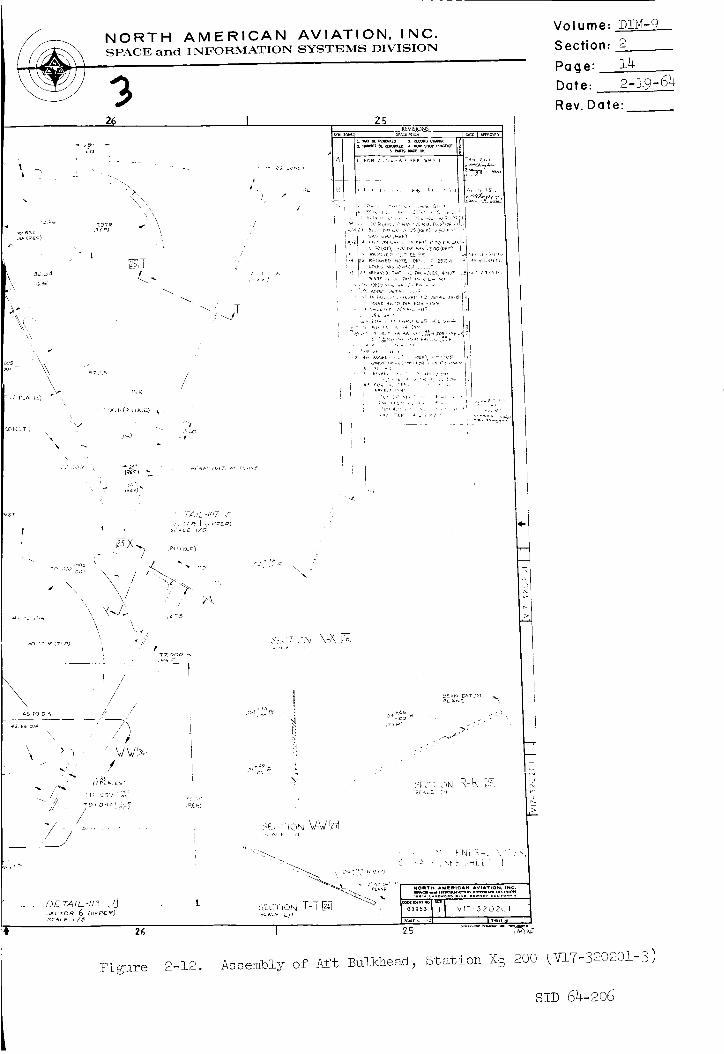
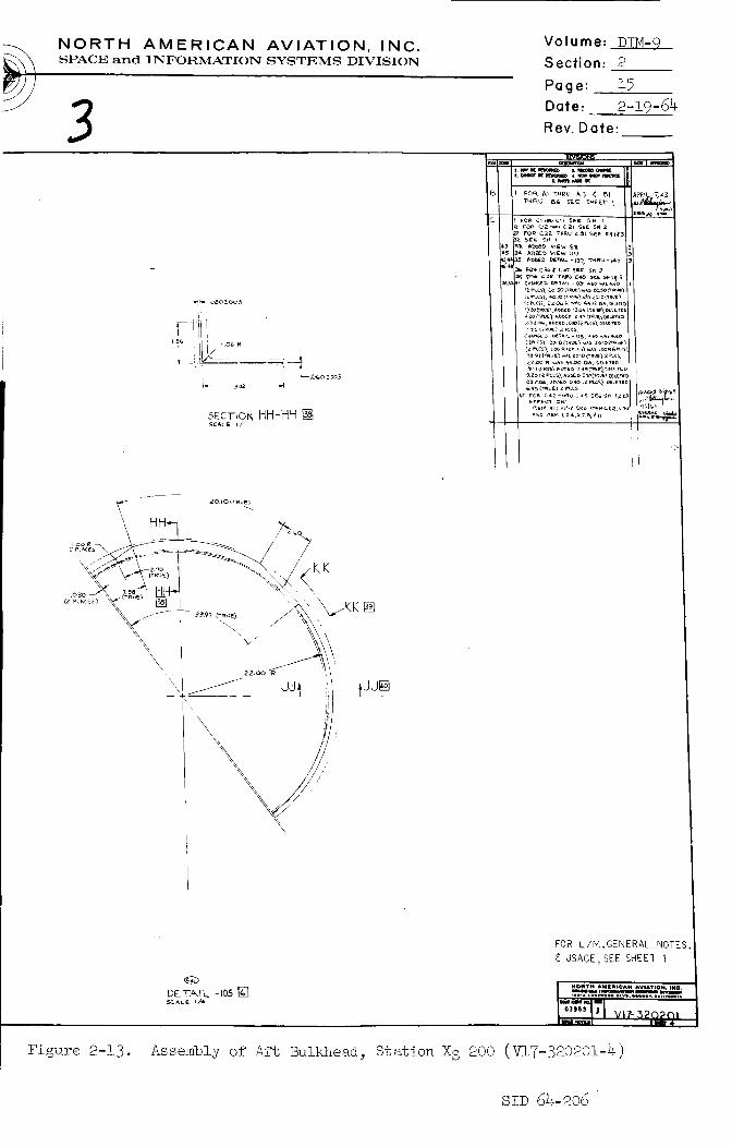
Assembly of Aft Bulkhead, Station X S 200 (V17-320201-3)
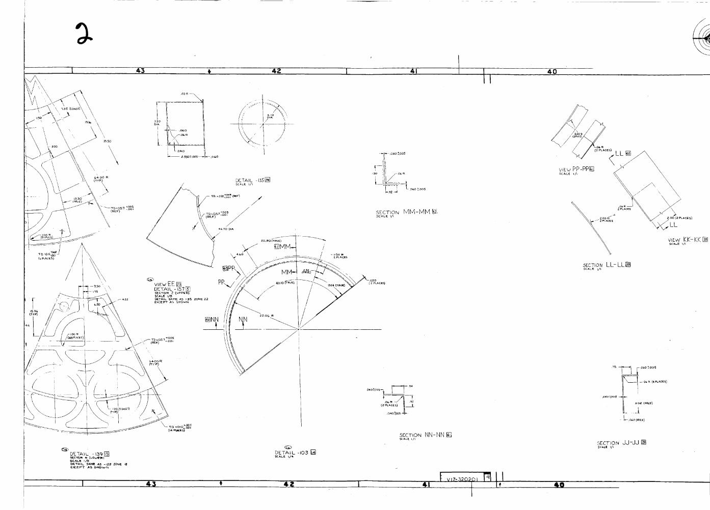
Assembly of Aft Bulkhead, Station X S 200 (V17-320201-4)Assembly of Radial Beam 2 (V17-322001)
Adapter - GeneralAssembly (VI$-000002).Design Study - Configuration - S-IV B Adapter (V2¼-932002)
Manufacturing Assembly Breakdown of S-I Adapter (SK-015129)
Skin Panel Splice for Adapter Plate (1718-300011) .
Installation of Main Propellant Tank, Service Module
(VI7- 340001 )
Tank Assembly Complete: Main Propellant, Oxidizer
(V17-342001)
Tank Assembly Complete: Main Propellant, Fuel (V17-34;001)
Tank Assembly: Main Propellant, Oxidizer (V17-342002)
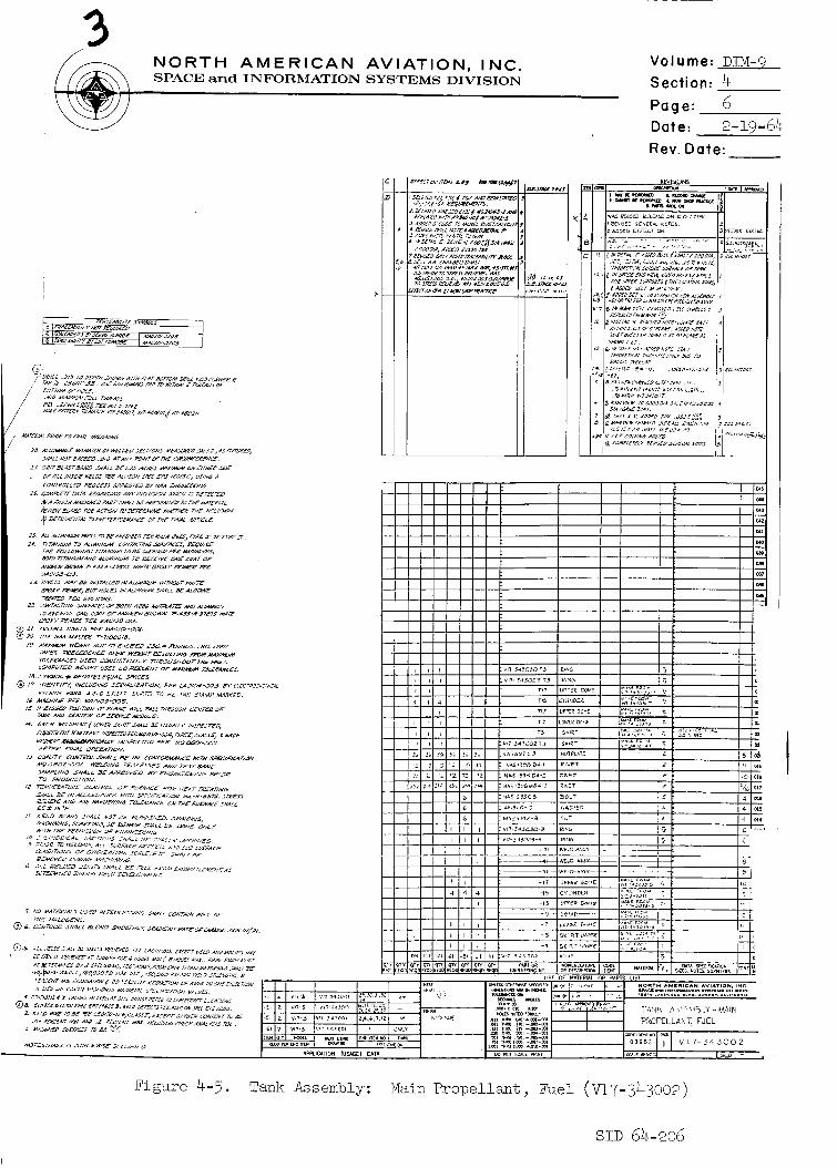
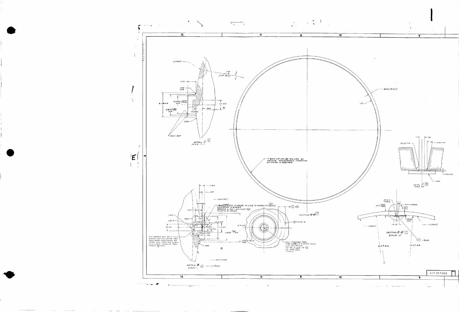
Tank Assembly: Main Propellant, Fuel (V17-343002)
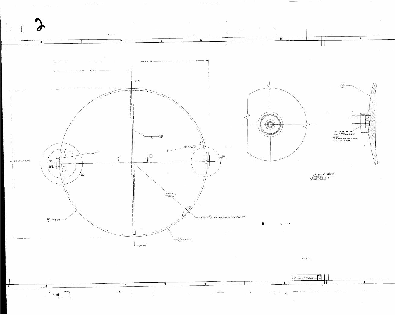
Tank Assembly: Main Propellant, Helium (V17-347002) 4.02 _Assembly of Upper Skirt Support, Oxidizer Tank _V17-3 2 P)i
Mounting Provisions, Environmental Control System
Installations (V17-331717-I)
Mounting Provisions, Environmental Control System
Installations (V17-331717-2)
Mounting Provisions, Environmental Control System
Installations(V!7-3317!7-3) . • .Assembly of Oxyoen Tank Shelf Support (V17-331667) • •
Module Installation of Reaction Control System (V17-332000).
Panel Assembly Complete, Reaction Control System (V17-332001-I)
Panel Assembly Complete, Reaction Control System (V17-332001-2)
Panel Assembly, Reaction Control System (V17-332002-I)
Panel Assembly, Reaction Control System (V17-332002-2)
Housing Assembly, Reaction Control System (V17-332010)
Longitudinal Heat Shield Installation, Reaction Control
System (V17-331525)
Page
1-2
1-3
2-2
2-3
2-4
2-52-6
2-72-8
2-92-11
2-12
2-13
2-14
2-152-16
3-2
3-3
3-4
3-5
4-2
4-3
4-4
4-54-6
4-7
4-9
5-2
5-3
5-4
5-55-6
5-8
5-9
5-1o5-ii
5-12
• 5-13
SID 64-206

e NORTH AMERICAN AVIATION, INC,SPACE and INFORMATION SYSTEMS DIVISION
Volume: DIH- 9
Section:
Page: vi
Date: 2-19-64
Rev. Date:
Figure
5-12
5-13
5-14
5-15
5-16
5-17
5-18
5-19
5-20
5-£1
5-22
5-235-24
5-25
5-26
5-27
6-1
6-2
6-3
6-4
6-5
6-6
6-7
7-1
7-2
7-3
Lateral Heat Shield Installation, Reaction Control System
(v17-3316N)
Insulation Installation for Reaction Control System
(V17-332046)
End Mounting Assembly of Propellant Tanks_ Reaction Control
System (V17-332041)
Mounting Assembly, Propellant and Pressure Tanks_ ReactionControl System (V17-332042)
Installation of Engine Mount_ Service Propulsion System
(V!7-327!01-I) .
Installation of Engine Mount, Service Propulsion System(V17-327101-2) .
Mounting Provisions Installation, Service Propulsion System
(V17-331000)
Mounting Provisions Installation, Service Propulsion
Pressurization System (V17-331100).
Mounting Provisions, Electrical Power System (V17-331552-!)
Mounting Provisions, Electrical Power System (V!7-331552-2)
Installation of Fuel-Cell Mounting, Stabilized Shear Web
(V17-331524) .Assembly of Support Shelf_ Upper Hydrogen Tank "(V17-331566)
Control Layout - Electrical Power System Radiators_ SectorsOne and Four (V17-933074)
Installation Provisions_ Fluid Lines Suppoz_t, Electrical
Power System (V17-331553-i)
Installation Provisions_ Fluid Lines Support_ Electrical
Power System (V17-331553-2)
Installation Provisions_ Fluid Lines Support, Electrical
Power System (V!7-331553-3)
Outer Shell Assemb!y_ Aft Heat Shield_ Sectors Three_ Four_
and Five (V17-331944) •
Inner Shell Assembly, Aft Heat Shield, Sectors Three_ Four,
and Five (V17-331700)
Installation of Aft Heat Shield_ Station X S 200
(V17-331689-I)
Installation of Aft Heat Shie!d_ Station XS 200
(vr(-331689-2) .
Insulation Installation Provisions_ Service Module
(V17-331562-I)
Insulation Installation Provisions_ Service Module
(V17-331562-2) • •
Complete Assembly of Thermal Simulator for Specimen Test
(DTT-6600) - -
Installation of Fairing V17-310001-I)
Installation of Fairing V17-310001-2)
Fairing Panel Assembly_ Service Module to Command Module
(WT-311ool).
Page
5-14
5-15
5-16
5-17
• 5-18
5-19
5-£0
5-21
5-235-24
• 5-255-26
5-27
5-28
5-29
5-30
6-2
6-3
6-4
6-5
6-7
6-8
6-9
7-2
7-3
7-4
SiD 64-206
NORTH 'AMERICAN AVIATION, INC.SPACE and INFOR_ATION SYSTEMS DIVISION
Volume:_
Section:
Page: vii
Date: 2-19-64
Rev. Date:
Figure
7-4
7-5
7-6
7-7
Fairing Assembly Complete_ Command Module to Service Module
Umbilical (V17-331771)
Assembly of Support - Command Module to Service Module and
Fly Away Umbilical (V17-331913)
Strap-Tension Tie_ Service Module to Adapter (V18-300005)
Control Layout for Servicing and Umbilical Locations
(V17-933401)
Page
7-5
7-6
7-7
7-9
SID 64-206

NORTH AMERICAN AVIATION, INC.SPACE and INFORMATION SYSTEMS DIVISION
Volume: DIM-9
Section: _2L__
Page: i
Date: 2-19-64
Rev. Date:
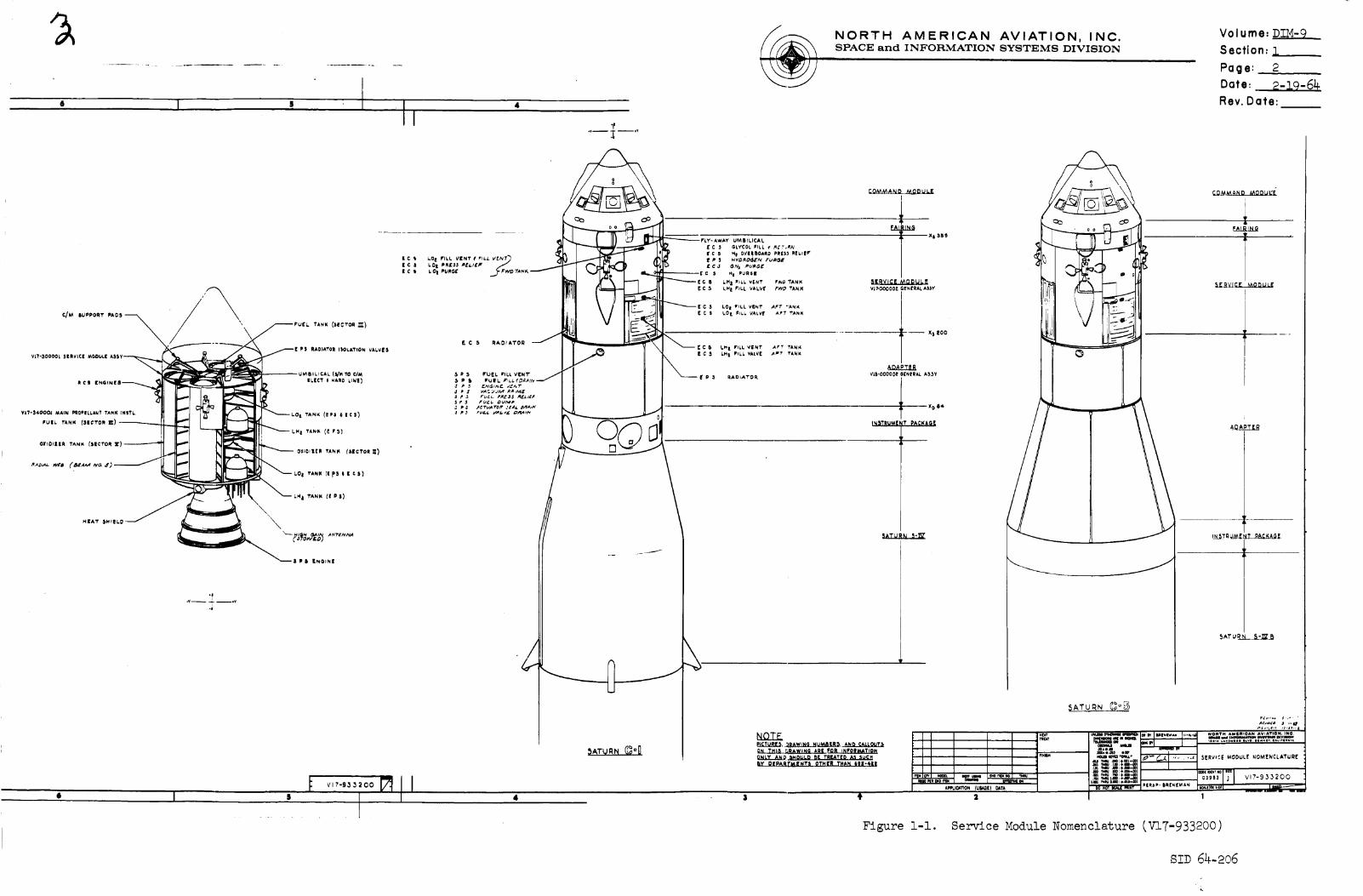
1.0
i.i
i.i.i
I.i.2
1.1.3
1.2
1.2.1
INTRODUCTION
General
The Apollo service module is pictured in the layout V17-933200,
"Service Module Nomenclature 'f (Figure i-i). This layout provides
names and basic details of the S/M_ the fairing_ and the adapter.
Drawing V17-000002 (Figure 1-2) is a perspective of the S/M
general assembly.
This design information manual (D_) presents the structure of
the S/M, the adapters, the tanks of the service propulsion system
(SPS), the mounting provisions of the S/M systems, the signifi-cant interfaces.
The systems of the S/M for which mounting provisions must be
designed are: the SPS, including the S/M aft heat shield; the
reaction control system (RCS) plus its heat shields; the environ-
mental control system (ECS); the electrical power system (EPS);the telecommunication system (T.S.); and the internal insulation
system (I!S).
Reliability
Information furnished by the Reliability Engineering Group for
this manual is classified, but DIM-9 is unclassified. Hence,
reliability information_ advice, or completed studies may be
obtained by contacting Department 643-50.
SID 64-206

NORTH AMERICAN AVIATION, INC.SPACE and INFORMATION SYSTEMS DIVISION
Volume: DIM-9
Section: 2
Page: ]
Date: 2-19-64
Rev. Date:
2.0
2.1
2.1.!
2.1.2
2.1.3
2.1.4
2.1.5
2.2
2.2.1
2.2.2
SERVICE MODULE STRUCTURE
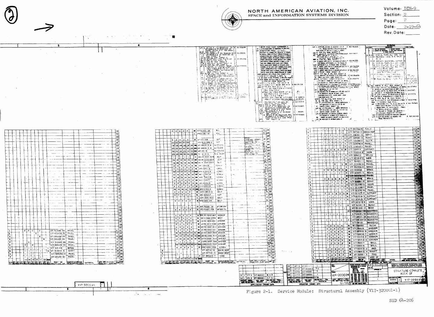
General and Configuration
The service module structure consists of the outer shell_ radial
beams_ forward and aft bulkheads, and inner web. (See 7.2.1 for
analysis of the fairing.) Drawing V17-320001 (Figures 2-1
through 2-6) depicts the structural assembly of the S/M.
The definition of the present S/M configuration required studies
in space allotment for its systems and equipment. Design
criteria were the factors of access_ removal_ and servicing.
Both structural design and choice of materials were based on the
exigencies of space environment.
The S,/M is 155 inches long and 154 inches in diameter. The outer
shell is made of one-inch aluminum honeycomb sandwich; the radial
beams of aluminum plate are made by numerically controlled
machining_ followed by chem-milling; forward and aft bulkheads
are fabricated from aluminum honeycomb; and the inner web ismade of aluminum sheet.
The six radial beams divide the interior of the S/M into three
pairs of diametrically opposed sectors which are unevenly sized.
Desigm layout V17-93556! (Figures 2-7 through 2-8) illustrates
the complete interior arrangement of the S/M. A center section
which is 44 inches in diameter extends the length of the S/M.
The function of the S/M is threefold: a) support of the main
engine of the SPS; b) housing of the SPS propellant tanks;
c) housing of all other systems not contained in the command
module (C/M) but required for the spacecraft (S/C) mission.
Component Description and Function
The outer shell of the S/M is formed by bonded one-inch aluminum
honeycomb sandwich panels. This material was chosen for fabri-
cation of the outer shell because it provides the greatest amotunt
of strength and rigidity for the least amount of weight. In
addition_ its simplified structure reduces the number of parts
needed_ handling_ and inspection. Also_ reliability is increased..
The outer shell of the S/M contains the space radiators (ECS
and EPS) which form an integral part of the outer face sheets of
the aluminum honeycomb sandwich panels. It also supports the four
RCS modmles. It distributes the C/H and S/M equipment loadings
from the radial beams into the S/C booster. In addition_ it resists
aerodynamic pressures_ provides a clean aerodynamic shape_ and
protects the S/M interior from external environment.
SID 64-206

1,J It t 10 I
t
i
..................... ._\ . 1.
, I
"""'_1 F [ p b RADIA'.r0R I._)01,ATION VA!,V[ (4 PLACII_)_
Rl[LAV t _Wl.rO_ I_OX (l[.R_)---\
,D,_o_.r,o.... *--"x \ \--
I_.,"c:_ II / / / _-'VLT'3$l[0O/. MODUL|A$_IY (_ PLACIS_
LO t T N_(S
_,LO X I[NGINI_ -_
\
s I 7 t

I T 4'
I 7 t
6 1 =
NORTH AMERICAN AVIATION, INC.
SPACE and INFORMATION SYSTEMS DIVISION
* I s
LL_Xll SB S
--- X_ 800
5E_VICE MODULE
VI'_OOOOOE GEN_PRAL A_$Y
X D 86
V_'OOOOO! IENl_A!. A_'SY
INSTRUM[ T PACKAGE
./
U
},_TVRNC)°0
J
NOTE_l 3RAWIND NUM&ER5 AN_ CALLOUT&
ON THIS _AWIND ARI _OR tNROI/_ATION
ONLY AN_ &MOULD BE TREATED A_UCH
EY DEPArtMeNTS OTH_ THAN 6l_'6ll
_T_V.3L=:_
TAPPLICATION (Uli/_[) _A'rA
Volume" DIM-9
Section: 1
Page: 2
Date: 2-19-64
Rev. Date:
C,Q_ _A A N D _AO O U L'E"
Figure i-i.
_ATURN C_°_
_¢IICMN_'_'IIIINI_$11_q _lPt I,mEWII_N _-_,,-_ NORTH AMllqI_AN AVIATION, INQ.
_ m
J_,*.mO *IP +_ _ ,,....z
mmmt, mm*omu.. S_RVI¢_ MODUL[ NOMENCLATU_[
,_1 _+ml_ 039_3 j V17-933200
00 NOT _ _l_ Icw_p*l_,ll II_lz.------_
I
_Br
mN_l_
m_Na
pmw,_ ON
Service Module Nomenclature (VIT-933200)
sz; 64-2o6

12 I
ii II
to
Vl7-3_Slg t REQ'D
ti It
I
Vl?'- _1_i551 t I_Q'Dvl'r- 4,50001 ) ltff.il'ovt?- 4_ioool I RIIO, DV'lT- 4=30001t i ltEO'{:lvr't- 4,r,_ooo_l ) ItEQ'I::)
VII'- 3_1_l. t REQ)D
I I
\
Vi7- 3000 Ol I REQ'D
VIT- _1000 i REG)'
V_7-40OiO_ i lliO'l::)Vl7- 4'00103 i IIEO';
I ,I

' I
NORTH AMERICAN AVIATION, INC.SPACE and INFORMATION SYSTEMS DIVISION
Volume: DIM-9
Section: I
Page: 3
Date: 2-19-64
Rev. Date:
s I " I
/
//
4 I
(RE_)
VIT- ¢(000I I P.EQ'D
Figure I-2. Service Module:
L
General Assembly (V17-000002)
SID 64-206
\\
,o I
1
u T°'
SECT K-K5C ;kLE VZ
SECTION d-d []
/-
?
8 I 7 +
Xs 2.00
LT LRR
..........-_............4_ll__uu
_,._ .____,____,,_,_____,_d
_. "_i_$ I_LI41_IZ_.4. I_ I_t)_CUL_ "to 5T_C_ _OOUL_-_
:l.mlJl$$ _m-ql.l144i_It•l_O'tltt_
I $
Lq_ _s ,,--_ o V-Z, :_.?, v,^s
NORTH AMERICAN AVIATION, INC.SPACE and INFORMATION SYSTEMS DIVISION
Volume: DIM- 9
Section: 2
Page: 2
Date: 2-19-64Rev. Date:
V14-000024
UL,-UU
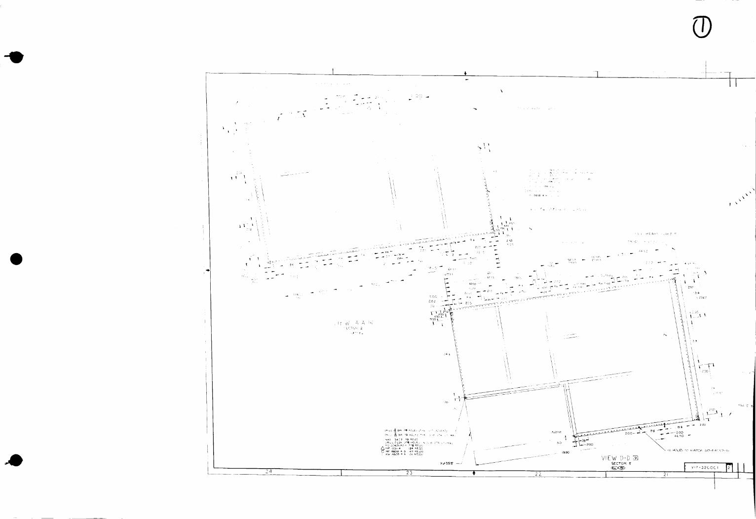
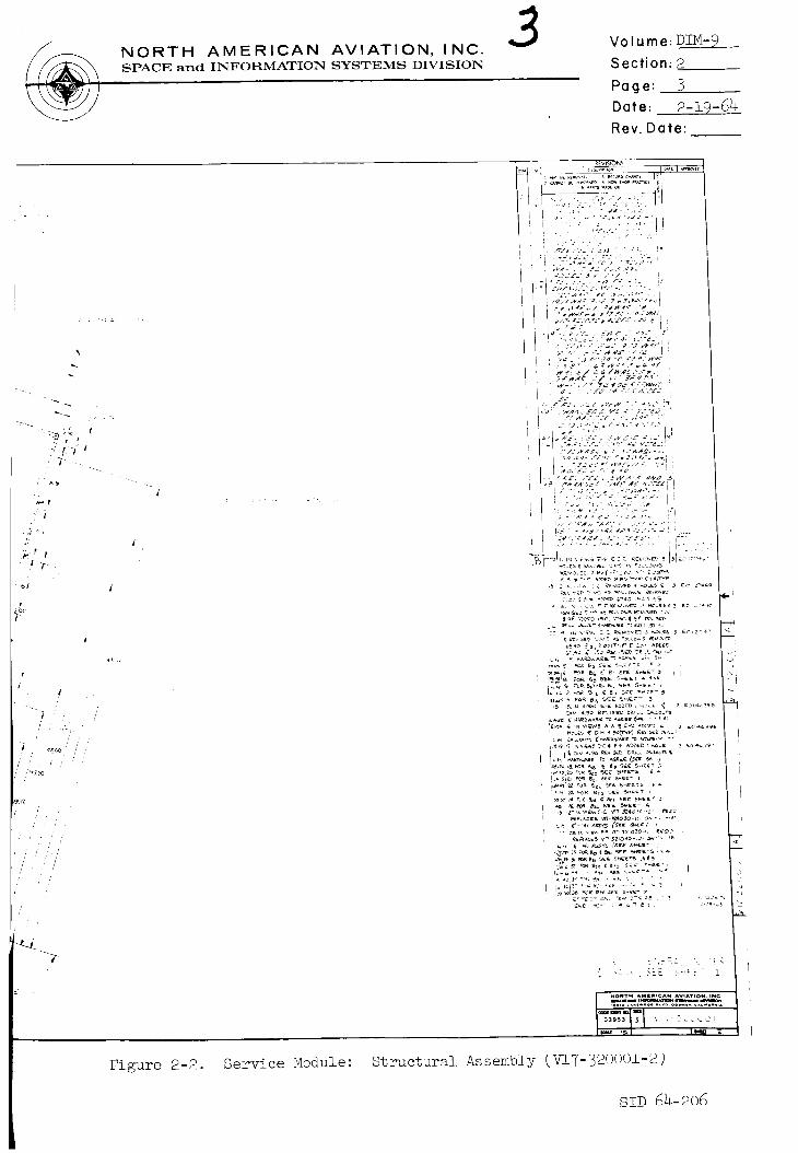
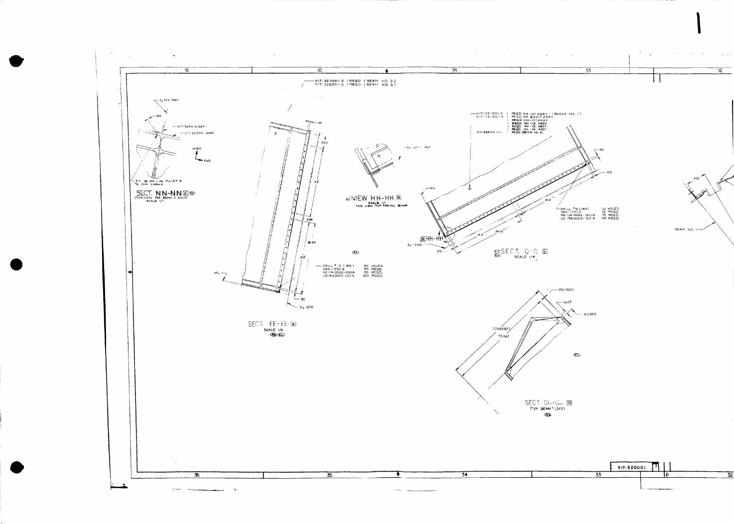
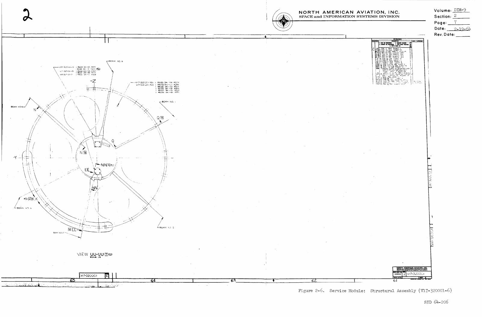
Figure 2-1. Service Module: Structural Assembly (V17-32000i-i)
SID 64-206
l
I
!
i
L ,;
k
_Z/-
LCTM, 2
w
_R,_L _C._ J_8_O,_- ¸ _ : ÷ _ .:._k;"IS 2e_ _ _8 RS_L ¸
C MF ,_08 4 _ 2_ _'EQ_'
! x
/
I,!
//
/ i
J
"I L
24 23
Xs-3SE SECTOR 5
./
P
• %'.
\
\ ",
R
LT: :_ . 2_:___..
2O
\
• d
_F
.p
\
£,
", %
_-'= ,
.... ,* % ",\
%%
\ •
%
4
- "%
• ?,
zcn
%
%
,k
%
%
v, c
SECI_ i, 4
/4" /
/
19
../
- . =_ -;', g _2.
De_LL _ O_ 2" _OLES _-_ • _ 3Z40_0
<
\.
:.C X
X x \ /
%
\
%"_ \
"%
_ , U _ L
SEC TO _ i
t
%
%
\
p
-, s'
18
i
4"
4"
A.
z
_'/'2 •
_z
.,= _- = _, REQP
17
Ii
! -
Z
d
,/
t
t t .'_
/
¢- ,/
//
///
:,K'
%,
f
/
/
/
/
16
NORTH AMERICAN AVIATION, INC.SPACE and INFORMATION SYSTEMS DIVISION
l
3Volume: plM-____
Section: 2
Page: 3
Date: 2-19-64
Rev. Date:
Figure 2-2. Service Module: Structural Assembly V17-3200()i-2
S!D 64-906
I
36 I 35 _, 34 I 33
--VIT-32300P3 r REOD { _EI_ kO. 5)
i
/
//
i
,/
/
SECT. EE-EE%C_,LE I/4
\
®
_5 35 34 :53
:+
I 31
/
30 I 29 II28
×
X
1500
\V@
VIEW R-R ,,-s3SCALE Xl_=
29 28
NORTH AMERICAN AVIATION, INC.SPACE and INFORMATION SYSTEMS DIVISION
HOLB5 (_RV _I'7-SZ4OTO3
, REQO
REQOAEQ O
"[RACE X, 26o,370
1-37__4050-Zl I REQD
Volume:DZM-9
Section: 2
Page: 4
Date: 2-19-64
Rev. Date:
FOR L/M, GENERAL NOTE
USAGE, SEE SHEET t
I NelITH AMIIIIeAN AWAVlON. INe.
ImlMl,,Ii_ _ IIVIIImlllill IIRIWlOD ILVD, DoWN I,, I _il,llll A
--,qTio:3gs V 17-5 ;)000 I ]
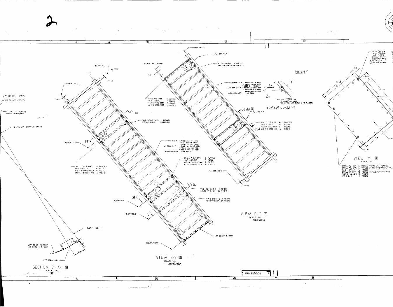
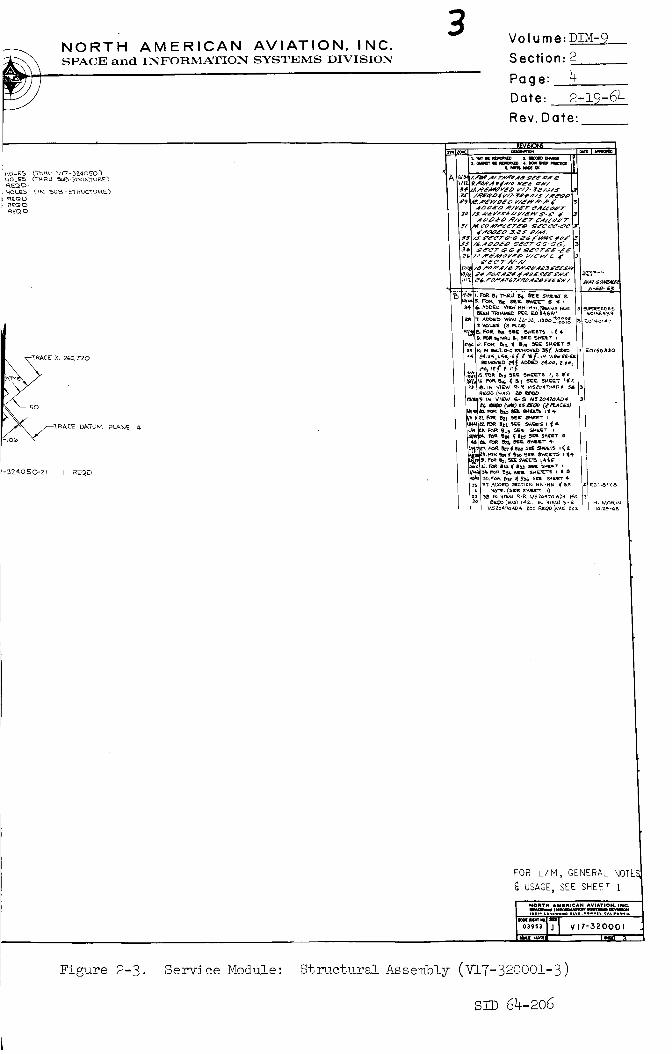
Figure 2-3. Service Module: Structural Assembly (V17-32000!-3)
SID 64-206
":" q < " # 4_,
....,i__w' 9BtTY_ FOR %ECT'OR __ _ 5ECTOR 5)
5C_xLE I14
/
/
/
/ //<
/
///
/
/ //
/
/
//
/
/
/'
//
I
// ,I
I ,15
//
I
/
\
]
4s I 47 ¥' 46 45 i v,, 2ooo,,
-t 4 ,42
SECTICI4 F_-FF_ ,,_",-_ tom ST_ _5_50 (_3_0o
SC _xLE I/.4-
"N
S7_ 11 'N Db-bPh<_CAL[ i/I
44
41
_ • : s,r_ \
\17 120g_5-3 * _{Qt
t _7 t2¢o _ z ._ ,.,
L
:£2 V<%1o22,%%%.......
, Vll.3ZO018-9 4 _._..i_
_DD "
\ X_ i I0
J_ 41
!
-_0
i
=5 9CL2 ,O4 m,£L:
f/
./
iN.
f
%
\
<
'{'K"9
1 h
SERVI_E r4oo_uE _L
VIEW P-P5C',LE _ 2
\\,
-T
\
<:_ :3 ¸ ,
/
_.j" ,.
%
%
NORTH AMERICAN AVIATION, INC.SPACE and INFORMATION SYSTEMS DIVISION
Volume: DZM-9
Section: 2
Page: 5
Date: 2-19-64
Rev. Date:
: DHZ o*, -o - _F 2O
<,v]7- BaOOfZ. 5 i R_O (_EAM "_}
LDIBB 0010 r,o_ _RgQD
',/IFW V/ \_ '.... ,'_'>
( :,.,oV,!, SIt 'P:i : :
•......... o °,.o _o......... ...,_
_ J VH'-32 OOI
4O
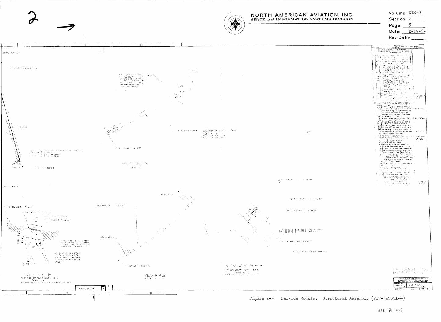
Figure 2-4. Service Module: Structural Assembly (V17-32000i-4)
SID 64-206
6O
//
f
[]
z b_,ILL"_ _aSP-j -CO DEP_F_ S_0WN_5 _OUE$ e PLACE%CO0eDmkT_ V4_T_ m5-3OOOO_
CUE_N UP _ DI_ AR_ _ S_
SE.C_T1054 LL-LL
6O
59 58
L I
_SF.Si& DIA ,B_h FILLr_.T R
NO'eg: CL OW Spo'r FAC_ _UST
_Ew MM i_5CAL_ _h
_BEAM NO,
/
+Z
_9
SECT T- T []/TYP :o_' _;/A¢ ST,4;'IO#_"
._d'41 [ /i_
58
57
I 57
I I 56
plF'3_O0/9 l t_z-q_
VIEW X-
.90AZE I-
_,_o0
\
_A_ II .5 _ Caj
_114-0002-0005
t v- ooo RII
.7
t_ s4 I 5355
\
\
\X X\
X9s
\
/ .,q,£-6'_
S_07 N-N []
\
I 55 i 54 F,_,
I
7.,eA_'E.I'03££
52 I
i
I\
V/E-I'Y B-,_ []
i_o'ri_ N_l{.li [email protected] Alll "I_ti _ AI IN_lK%l,I I-i (_lll II) i_T A_ kl0"fiO
s2 I
51
_BE A_'4 _qO. Z
//
/
I/IIII
II
. / /
/I
/
I
_,oo
I'
51
NORTH AMERICAN AVIATION, INC.SPACE and INFORMATION SYSTEMS DIVISION
3 Volume: DIM-9
Section: 26
Page:Date: 2-3-9-64
Rev. Date:
k'TC'_ GIg- 8\a057-Z%
_o I
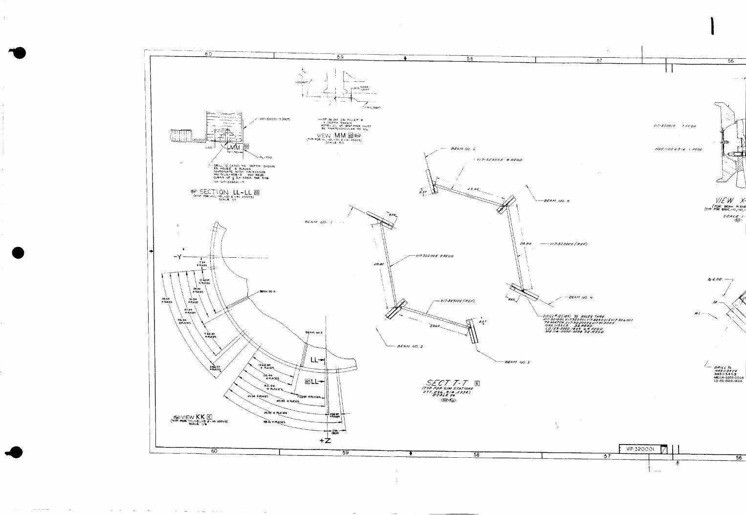
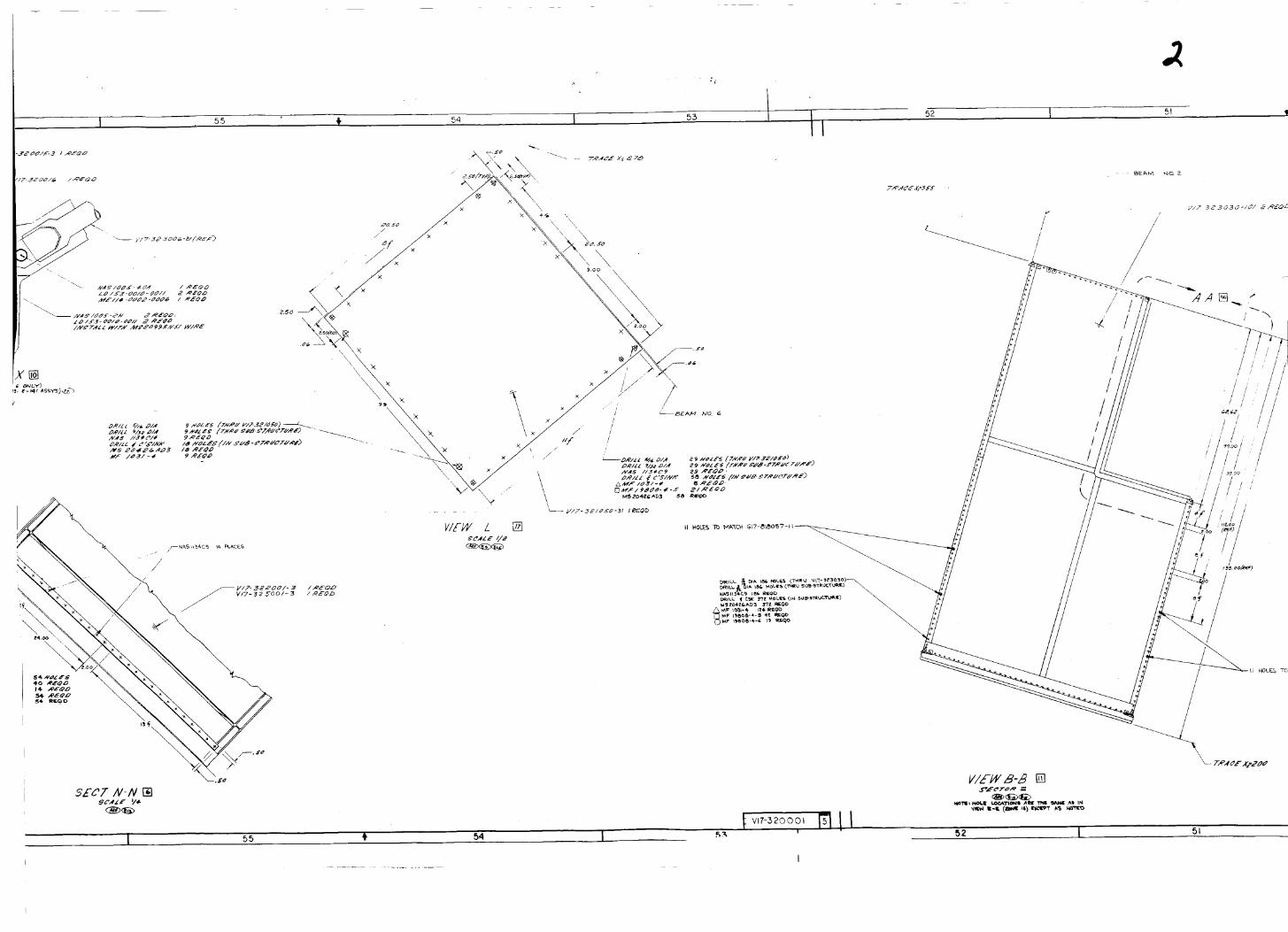
Figure 2-5. Service Module:
FOR L/M,GENERAL NOTES,_USAGE,SEE SHEET 1
I NOMT_ A_/RICAN AVI_ION. INC,o_ -520001
49 '_
Structural Assembly (VI-7-320001-5)
S!D 64-206
7_
• -' _" tim's', ' J', l,, _ i ,
71IH
a I ' t ,j
o 7o,.. ,. , . , ,.,,, , .
t Vl 7-320001
I.
67 t
.... '. ,,.: .._..'.. i i' . _, .:- , .., ....
66
'qIEW UU-UU _,_
64-
NORTH AMERICAN AVIATION, INC.SPACE and INFORMATION SYSTEMS DIVISION
Volume: DIH-9
Section: 2
Page: Y
Date: 2-10-64
Rev. Date:
r J
Figure 2-6. Service Module:
(-)
v"
2
imm II .lmll,mm mmu_ mYmm
-G?lv,7_s -320001
<ol
Structural Assembly (V17-320001-6)
S!D 64-206
12 +- 11 10
12
. - . • _+ _ .
I0
F
UPPER
SECTOR I
XS 2S_.5
\
/
/
/
//
t
t

"Z-_ omn2Td
Vl"_ 13_SO) NOfl.v_lld_V I
rm_ i'_l _r_ u m m
I
(............ ._)
\
Z
:e_.o C}"AeEI
:e [_Ocl
:uoN.o8S
6 -__T.__:euJnlOA
NOISIAI(I SIAIS[&gXS MOIJ.VI_IItO_M[ pu_ _O¥-dS
"DNI 'NOI.LVIAV NVDl_l:ll_lV I--t.l._lOt',l
7
\\
!
_L _¸
_L. TANK
/
L
t l . it i _ i i JIlLv
I
S_t,,'tO_ I
5¢CTOR t
DATUM PLA_E 6
/
24
1
• " _ iI_._.__ _ __._.._.___.__.._/_ "_lill_ "_1_
--Y'.SHO\yINEi R.C,E,. _R UNIT
j-

--Z
•,¢,,o,. D- D []v_v LoraK_ AF'r,
1,6 _b
/_ NORTH AMERICAN AVIATION, INC.SPACE and INFORMATION SYSTEMS DIVISION
iii -:=-'-:'-----C----lIC-
\
/
/
+Z'
,,_,.o.__r-r[] .,,, .... 'oVIEW LOOKING AFT
|._-".... _ ---_
I_ _ -
Figure 2-8. Complete Interior Arrangement of
Service Module (V17-935561-2)
Volume: DIM-9_
Section: 2
Page: 9 ,_Date: 2-!9-64
Rev. Date:
SID 64-206
e NORTH AMERICAN AVIATION, INC.SPACE and INFORMATION SYSTEMS DIVISION
Volume: DIM-9
Section: 2
Page: !0
Date: 2-19-64
Rev. Date:
2.2.3
2.2.4
2.2.5
2.2.6
2.2.7
2.2.8
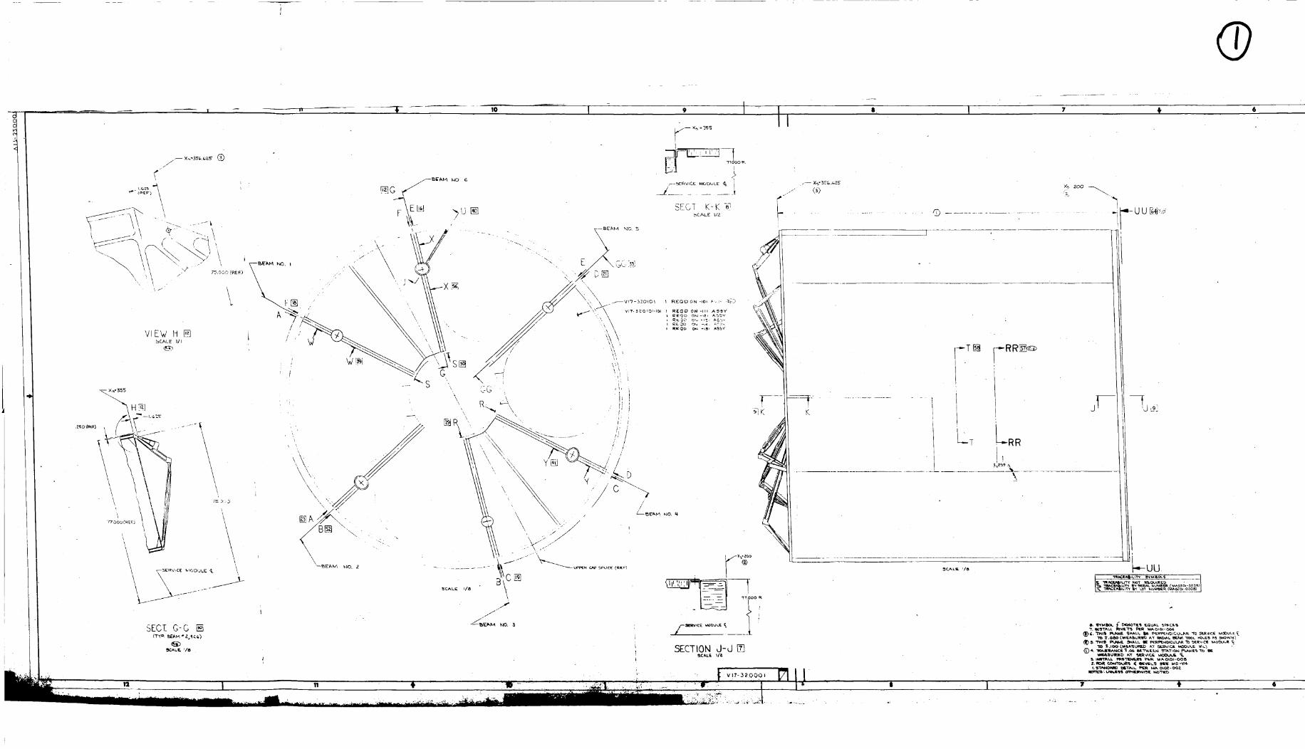
Panels which form the center shell or web are made of aluminum
sheet 0.016 inch in thickness. The web structures are found only
along the center lengths of Sectors 0ne_ Four_ Six and Three.(See dra_ngs ..... F, -_'Ii-_3;;om, Figures 2-7 through x-o, and Vi7-320001,
Figures 2-1 through 2-6. )
The function of the center webs is twofold: a) to aid as stabili-
zers for the six radial beams; b) to distribute the weight of the
helium bottles and the engine mou_ts which are located in Sectors
One_ Four, Six and Three.
The aft bulkhead is made of bonded aluminum honeycomb sandwich
three inches thick and 154 inches in diameter. The center open-
ing coincides with the inner caps of the vertical beams and is44 inches in diameter. The forward bulkhead is made of the same
type of material_ has the same size of center opening_ but is only
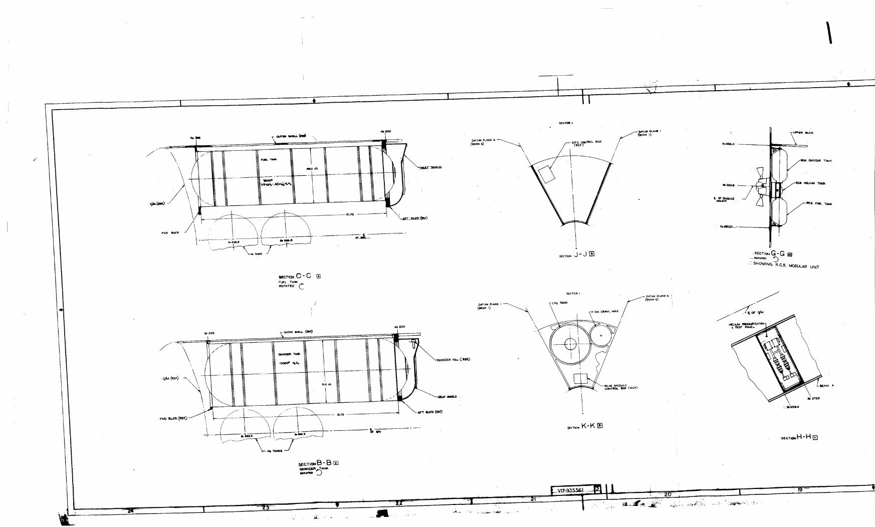
one inch thick. See drawing V17-320101 (Figure 2-9) for the for-
ward bulkhead_ and drawing V!7-320201 (Figures 2-10 through 2-13)
for the aft buli_head.
Both bulkheads distribute the radial beams' loading into the outer
shell. The aft bulkhead per se acts as support structure for the
SPS main tanks_ the SPS engine and gimbal mount_ the radial beams_
the EPS fuel cel!s_ the cryogenic hydrogen tank_ the aft heat
shield_ the high-gain antenna_ hard lines_ electrical wiring_ etc.The aft bulkhead also serves as a heat barrier between the SPS
engine and the S/M interior. The forward bulkhead provides
lateral support for the upper ends of the SPS main tanks.
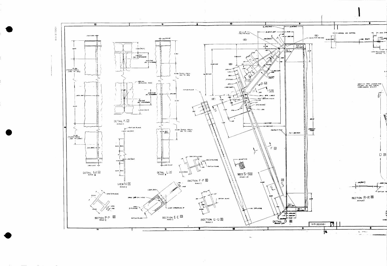
All radial beams have similar configurations. Each beam is a
rectangular structure machined and chem-milled from 2.5-inch
aluminum-plate stock. Each has a minimum web .0iS-inch thick
and stiffeners .06-inch thick. The vertical distances between
stiffeners vary between 6 and 19 inches. For a typical beam con-
figuration_ see drawing V17-320001_ "Assembly of Radial Beam 2"
(Figure 2-14).
Criteria which governed the choice of radial besom configuration
were: a) the length of the main SPS tanks in their final con-
figuration; b) accessibility to these tanks; c) weight and fabri-
cation savings through the use of numerically controlled machining
and chem-milling instead of the use of more conventional methods
including welding of structures.
SID 64-206

c_
12 I 11 t Io
t
\\
I .......
i
[_l/ts!c _!ssY) P:/7-_i,-lll_'d-J',ll#_'
_(_l,_/ .4Sl'i'.) VI't-3Z3OZO-61 I: lU
/
\
,/
//
/
:i
¢'TYP •
F
//I
/
//
/
I
/
/
/
//
/
\
"'--'- "----.
<PEF_
j/"
/
E/
/ /J
/_x'._' I¸
III
/
J.
/
\
-.-._..._
a[_l
\
mfO _'OA_
4 I 3
\\
.#/w-_a,w o_/f'.mhp)
_OJ
!

NORTH AMERICAN AVIATION, INC.SPACE and INFORMATION SYSTEMS DIVISION
,_,. f,,_,t,--)
1
Volume: DIM-9
Section: 2
Page: ii
Date: 2-19-64
Rev. Date:
Figure 2-9. Installation of Forward Bulkhead (V17-320101)
SID 64-206
o
L
12
z'51'
ITrPJ
.050 --(TYF9
o_ X.O05FOR -x{,q
\<
L.c rrrl
• Ii L
lilO0 C_A
-tO3
S_CTIONGG-GG C__iC_l.! I/I
(_
Vll-llOlOI
_.-_!.I.. .

.It
B_M 4
, I
\
\
f I
[]
TY_C_,_. SECTORS 2 _ 5
-- sfc?oR 2..
_.£Q# FOR-4,01
4 l
,54_CT0_
.f-
Ot_tPf
mlllON J
&_,O0 Mill
/
r
..... _o, _ _1
u , I • t
mill l._Olll_-O_l
II il 11 _ _I ....
RI BmON
DATU I_ PL/4N_
FF_
RI_ON OIRk-'r_T_O_ '4
"_ I REQD FOR - 30_ #-50_
FF
FOR Z_I _ l-wry Z_, s_¢ 5_¢_T
f .,,-.o,o,_ I 1, t .11_.1....... I*
MA OlO1 -_l
" _':':&"_',t,'_,_" ;,t,°'°''_" ; .......
4

NORTH AMERICAN AVIATION, INC.SPACE and INFORMATION SYSTEMS DIVISION
Volume:_
Section: 2
Page: 12
Date: 2-19-64
Rev. Date:
Figure 2-i0.
I
zL for cz_ l_u C_ SE_ SH • L
i
[
_ emv 1 _ _ w_
rl_ 3 l_ w_S mo o_ - _m ¢._ iimOl M _or.m_S
/ / ...... , .......... 1 .........
// ............." '/
NN _ REMOVED G/N _10 _1
_z. FOR C_Z T_O cZO $_s _
-1....-[-{7 CC;RE
[ __
Assembly of Aft Bulkhead, Station XS 200 (VJ._7- 32020]..-i )
SID 64-206

I
24 I 2_ i 22 I 2_
\
\ \\ ,.,.,,,
DETAIL -#Z5 []
//
/i
_vv
19 f 18
DE TA // - I l l
ZO
S_CT/ON K-K []
1
SECT�ON H-H_SCALe 2/I
o -.oo o
scc T/ON J-d []$CAL_ 2/i
._CTmNG-G[]
19
M,D
(rrP) /
_crloN N-N_¢4¢1I I/,
18

9o_-99 _IS
• • m I
00_ TX UOT%_%8 _p_oq%Inff %_f jo XlqmossV "II-_ omnBT£
////,////
/
,i I
[] j-j No_
[] 8-a No_o_

I
IP
3_ - - q---
_Cza
wEw W_d 126L_E_A/L -_51 iTSECTO_ _ (u_eaR)"
DgTAIL "3A_t£ AS i14 ZONe. £_-LXCa_T As S_O_N
d/ id
_cc
!
2, oo
:r
!
P
#,, - .,,.
_oosTD:05%oo, .
36
35
\ \ \\ /h,',\ \ \\ _
\ \ " _, 2oo
\/%
>_ ff LL
._.E-
\\
%
!
,,a
VIE /V RR hs]
..,y"
/,x
35
:_A,_ _9 ¸ L+_
-_¢ co b,m?s =
\I
/ i _
_x
. tA_k
\
\,
\\
\
\
4- /
/
/
• HAC[ ZC LllxiE
/<
\
/>\
OZ3 [TRt}_- ')
\\\\\#,
,_.
,4_-"
?_,_I
I#,I
<< _ ,_t,L llt)lkl O0 -_0 i %
32
p
'/
/_ i II
,ooR ",
t ,
Ii
i
DL TA/L -1(;9 L8
5C_E '15
d.d Tm/V AA-AA_
., zo R
[ Z _Aca_
_' 25,0O
.50
I/. i
I:!
II
. &
:, !
'5- [_] ,'-_,.',_" TWL -27, 99 -Iql _-I3_ _
Ii
_ •040
_D
oNlY
1 t, 4, _Y/-')
,.,tw TT%
91 3O 29
2B
\.
:/-
x
e,
_AA_
A A-J ",e, .¢
-3 ,,_._,%oo I
/
_ _.--z " "- _-_"_":_":;
_E_/"" :":'--...___......... ;X" "'-,Z _'t _CESJ
2.7
'\
, "\ "\\,
'\\\X z7 %_,- a"
\
o:-.\ t_o, ul OOl
_L
:x" "
Ii TD s± ? i '} ',
i
I 85 f._ _L_:,LES)
\Z2 _o_sr
T
SC4LE ,
\
k _ x
\\\
"\1' \
\
'\\ \\
\\\h
/
z8 I _ '-''
NORTH AMERICAN AVIATION, INC.SPACE an4 INFORMATION SYSTEMS DIVISION
326 I z5
Volume: DIM-____
Section: 2
Page: 14
Date: 2-19-64
Rev. Date:
-_ooo
I
/J
--- DETAIL_-1/3 ,7j
_c TOR _ (UPP_)
J
2r_
Figure 2-12. Assembly of Aft Bulkhead_ Station XS 200 _V17-3_0_-3)
SiD 64-206

/
• /
wE_ UUL_DETAIL - 153_SECWO_ _ (UPPER)
SCALE _/_
DETAIL E,I, ME AS - 109 _ONIE 31
/ , I
\
DETAIL -1451_SECTOR _ (kOWER)
DETA_. $AI'I_ AS - _29 ZON_ 22,
;XCEI='I" AS s_ow_
4_ I #.t
DETAIL - 143 _-_.SECTO_ _ Ik.OV#e_)
OETA_L S_E AS -_27 ZONE 20
EXCEPT _1,5 S_Ow_
t 46 I 45
64
DETAI L - 1,37[]SF-CTO.R _ ('...o',,_R_SC_*LE I/_
EXCEPT _S s_owN
iI
/
./
4.5 'I, 42 41
DETA\L - _39 []
I:_E"I"/.,,,,_. _,l,t-g_ _,$ ll2 _ ZONI_ 18
E,_IEPT AS ._HO_VN
DETAIL -I0,_ []SCALE _/,,I-
I 4.._t
SECTIONNN-NN
4.1
4O
V_EWpp-ppl_ _>......,, \
X WEWKK- KKI_
SECTIONLL- LLI_SC_L_ _1
•_,-F-l_Fo°o..oos
o.¢o ".po_ -IF _o,!_ (R_.I =)
L _iL-.o_o (RE F)
SECTIONdd-Jd []SCALE I/_
II0
NORTH AMERICAN AVIATION, INC.SPACE and INFORMATION SYSTEMS DIVISION
] _ _,0_o Zoo53.OZ
SECTIONHH-HH []SCALE _/I
KK
Volume: DIM-9
Section: 2
Page: 15
Date: 2-19-64
Rev. Date:
FOR LIM,GENERAL NOTES
USAGE_SEE SHEEI I
I....i'i...................DE TAI L - 105[] ,.-,,_,.&_.,_._m..,_SC^L_ _/4 III,l_ I
I Ir_l i_rl_l II 4.
Figure 2-13. Assembly of Aft Bulkhead, Station XS 200 (V17-320201-4)
sz_ 64-_o6
12
DETAIL M []._ c._ L r.. i"
DETAIL L Izl
\
19 I !1
!o I
FF&]
F
\[]C
',\_
V_G--.°,_,,,-,°.-, \ \'t _
\ Ill.5
I--D _
--.. _ rv..oo-_II! ' : t_ .
®-t I"-'''_ _'_
ao I
i_El,Irr • f PE_. LAOIO'_-OOJ-_
[XCI_'-- O0 NOT _TAL
D_
\
5OCT,ONR-R []_CA6¢
I

II
\RI\11
.,.,,,,, f-;._oo ir.,o- f?.,,, [_:....... % r;.... = '"*"l
SECTION B-BI_.s c_,t F.. t
.......,................... -] _._IB _
l _-_,_t_ r_,_ "
t W <*"¢,, _'_ r-'_''_
I-L/ f l' " k If'v_ • _ _v . j.3-- Ls,_e_,) / _ - "
t ' t ' /_---- C_S_N_" TA_'_m
"I_0. =OIIO :l:.Oo.s
OXID. TANK BAY
NEAR SIDE
_-.II_ _ (e PLACES)(aI:_:
e•_.o..,OI10 =_oo!1
IN;. O0
• .D. -.ol8 ¢,005
/
i_.oo
- _.oo
.... _N.. j
t
]
IE
*'-_: : ..... ' ...... ._ _v .,q SECT,O.A-AF_...., i v.,, oo I
* * I , I I 4I
_ OA'r u/_ PLANE
I
* I
I I
L
I
V_EW H-H []._c A L_ J-
0XID. TANKBAY
•1, IBIIIlnP _, TlACll_t,l.rry _IIK 14AO¢01 -OZ,Olt
$ _. NVST il ,_f.A'r wITHIN !//@ #N_tvy O_REC7"IO/V
.5. DEI, IOT[t, "lr,M"_ 011'k_CT|O__.S'.'_goL _D- O[NO"r[l 'rI_ICKNeSIi 01,"_.I. COltI,II_I_ IqADII ,_8
I._U.¢'I" I_AOII ,1_L CNF._-#qlLL P[R /qAOl031-O0_ OR
,_,,t,C_IINI_ PI¢I'. /m._,oi0:lloOOIr
MOTES: UNLESS OTH_RWt_ NOTED
J
:-I .°'°('''
i _lll ,/_#._ ......
_FUEL TANK BAY
SECTION d-Ol_l_¢.,k L_ 5I-

_ NORTH AMERICAN AVIATION, INC.
SPACE and INFORMATION SYSTEMS DIVISION
mm_
.4l_,_e_ ,_#ILL I/i" # 7-O0,:.I,V_, ,<_,e! LocJr/NG DI_S/_t¢_
HOLiSj ,35 _tL,R(_p£CS) ,_lt, _i, _,
Volume: DIM-9
Section: 2
Page: 16
Date: 2-19-64
Rev. Date:
®
I
Fig-4re _-_. Assembly of Radial Bes_ 2 t v±7-jssOu±)
SID 64-206

NORTH AMERICAN AVIATION, INC.SPACE and INFORMATION SYSTEMS DIVISION
Volume: D]2vb 9
Section: 2
Page: 17 _
Date: 2-19-64
Rev. Date:
2.2.9
2.3.2
2.4.2
2.5
2.5.1
Functions of the radial beams are five: a) supporting structures
for the C/M; b) transfer fraznes for propellant loads from the aft
bu]_khead to the S/M shell; c) transfer framework for SPS loads
to the S/M and C/M; d) support structhres for aumi!iary equipment
pertaining to S/M systems; e) adjuncts to the outer shell for the
distribution of pressure loads.
O_eratin_ Conditions
In normal launch mission> the S/M with all its systems_ including
the SPS and RCS engines_ will successfully perform all of the
maneuvers required of the spacecraft (S/C) between lift-off and
reentry. Among these maneuvers are the following: earth orbit
with in-flight and ground-directed checks; injection into lunar
trajectory; transpositional docking with LEM; mid-course correc-
tion; translunar flight; f'free-turn _'trajectory; lunar orbit;
transpositional docking; and earth trajectory.
In a normal launch abort mission the S/H will use either or both
of its propulsion systems in operations designed to successfully
keep the S/C within orbit_ or return it to the earth.
Characteristics and Criteria - Component Design
The S/H outer shell_ fairing_ and radial beam structures will
withstand the aerodynamic heating during boost. The internal
structure of the S/M is designed for a temperature range between
-200 and +300 F_ although temperature and load conditions are
not always concurrent. The S/M structure is designed to withstand
hazards imposed by the environment as described by the environ-
mental requirements listed in the NASA Exhibit B. Technical
Specification_ Part !> dated 3 January 1963. These requirements
include resistance to the following: a) acoustics_ vibration_
and flight loads; b) extremes of humidity and temperature;
c) high a!titudes_ ground handling, and transportation; d) salt-
in-air_ ground winds> storm conditions_ meteoritic storms_ andradiation.
Other and more technical criteria which have been used to fix the
design of the S/H components are found in the.Apollo Requirements
Manual (ARM) -6_ "Structural Loads and Criteria."
Test Requirements
Test requirements for the S,/M outer shell_ fairing_ radial beams_
and other internal sti_uctural components including mounting-
provisions structures are specifically called out in SID 62-109-2,
"General Test Plan_ Research and Development for Project Apollo
Spacecraft - Individual System Test."
SID 64-206
NORTH AMERICAN AVIATION, INC.SPACE and INFORMATION SYSTEMS DIVISION
Volume: DIM-9
Section: 2
Page: 18
Date: 2-!9-64
Rev. Date:
2.5.2
2.5.3
2.5.4
2.5.5
Tests which have been completed and for which Apollo Test Reports
(ATR's) have been released are listed here:
ATR NO. NAME OF TEST
301-7
301-9
301-IO
301-12
301-14
301-17
303(213)
3o4
3o4-t
Joint - S/M to Adapter
Circumferential Edge Member
Longitudinal Edge Member
Structural Component Test - S/M
Outer Shell Pane!_ Blind RivetJoint Tests
Structural Component Test -
Aluminum Honeycomb Sandwich
S/M Honeycomb Attac_hment Test
S/MMeteroid Shielding
S/M Aft Bulkhead Structural
Components Test
S/M Aft Bulkhead Structural
Components Test_ Bulkhead Spliceand Shear Panel Tie
Tests which have been completed but for which no reports have
been written are these:
ATR NO. NAME OF TEST
301-i
301-3
301-5
S/M - Outer Shell Panel Test
S/M Simulated Aft Bulkhead Test
S/M Radial Shear Web Test
Scheduled tests as yet uncompleted are these:
ATR NO. NAME OF TEST
3OO
301-6
304-2
S/M with Adapter Static Test
Fittings - C/H Support
Aft Bu_head Component Test - S/M
ATR 600_ Combined Module Static Structural Test_ has not been
l%_q.
S!D 64-206

NORTH AMERICAN AVIATION, INC.SPACE and INFORMATION SYSTEMS DIVISION
Volume: DZM-9
Section: 3
Page: ]
Date: 2-1q-64
Rev Date:
3.0
3-i
3.1.1
3.1.2
3.1.3
3.1.4
3.2
3.2.1
3.2.2
3.2.3
ADAPTER STRUCTURE
General and Configuration
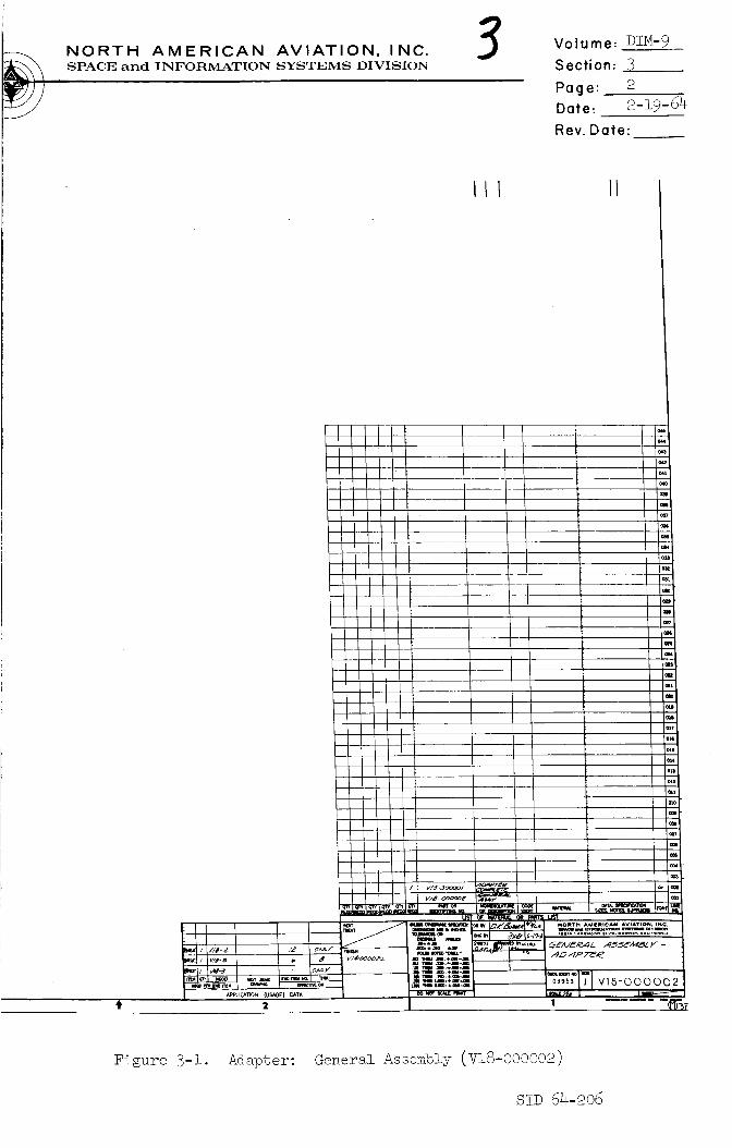
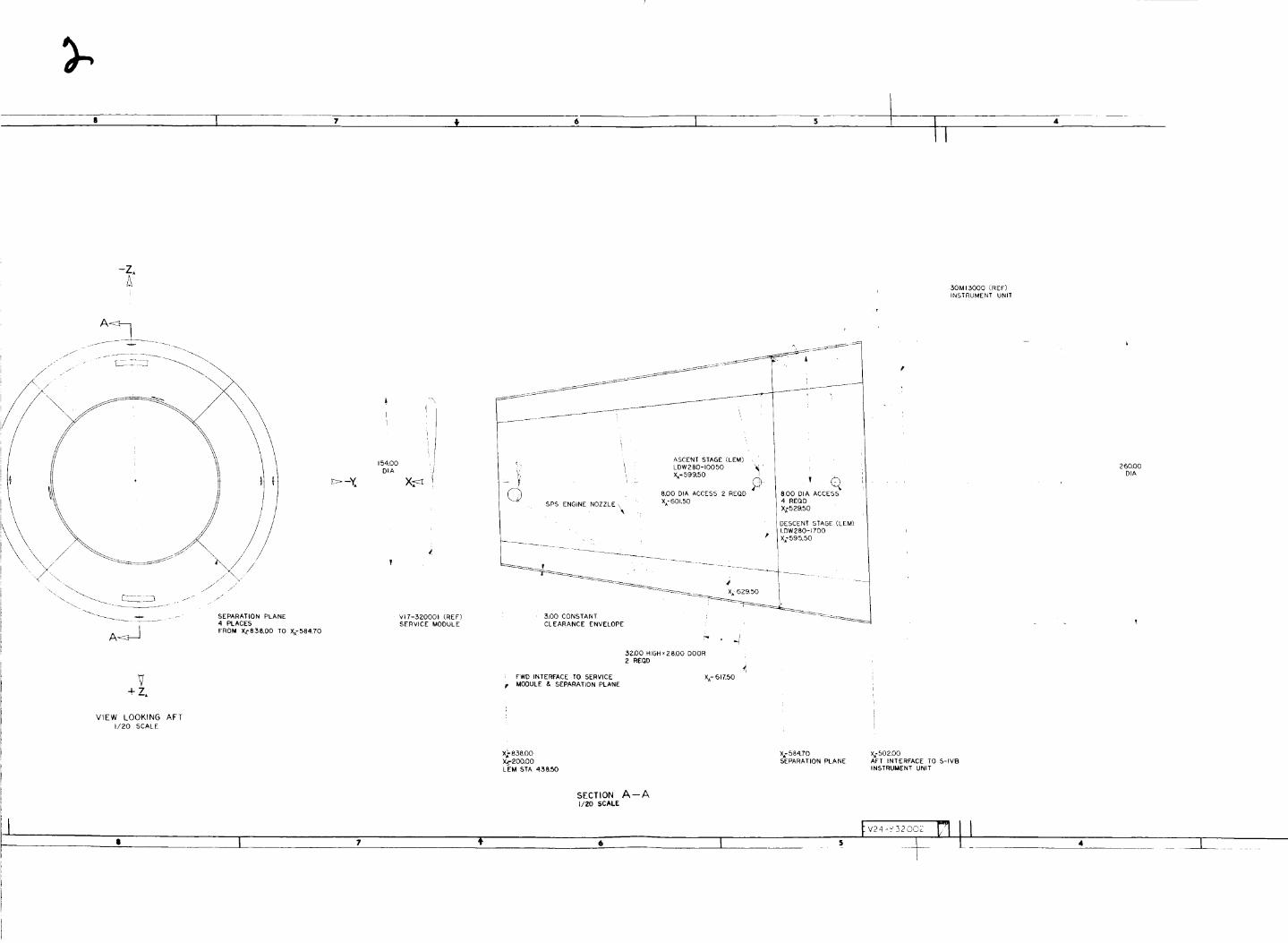
Two S_ adapter structures are in preparation: the S-1 adapter
and the S-5 or S/C L_ adapter. Drawing V18-000002, "Adapter
General Assembly" (Figure 3-i) shows the S-I configuration.
Drawing V24-932002 (Figure 3-2) pictures a design proposed for
the S-5 adapter.
Each adapter is a connecting structure between the S/M and the
instrument package. Each serves as an enclosure for the lower
portion of the main SPS engine and its attached cone_ the aft
heat shield below Station X S 200_ and the high-gain antenna in
stowed position. Each adapter is made of aluminum honeycomb
panels spliced together with pairs of longitudinal splice plates
of aluminum. Each adapter structure is equipped with shaped-
charge explosives for separation.
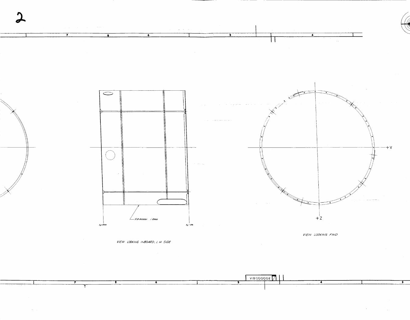
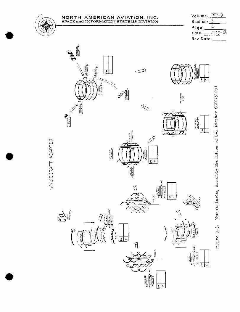
The S-I adapter is a cylindrical structure formed of four equally
sized rectangular panels which have a uniform thickness of two
inches. Location of the S-I adapter is between Stations X D 200and XD 084. Drawing SK-015129 (Figure 3-3) is the manufacturing
assembly breakdown for this adapter.
The S-5 adapter is a truncated conic structure with a conic angle
of approximately nine degrees. Its panels vary in thickness.
In addition to enclosing the same kinds of items mentioned in
3.1.2_ the S-5 houses and supports the lunar excursion module
(L_).
Component Description
The panels of both S-I and S-5 adapters are made of bonded alu-
minum honeycomb. This material was chosen for the same reasons
as those given in 2.2.1.
Four pairs of longitudinal splice plates made of sheet aluminum
O.06-inch thick are used to bind the panels of the S-I adapter
together. Drawing V18-300011, "Skin Panel Splice for Adapter
Plate" (Figure 3-4)_ displays details of the splice-plate config-uration.
The function of the shell structure as formed by the use of the
splice plates in both the S-I and S-5 adapters is as follows:
SID 64-206

12 I II iO
!
_¥
+Z
12 I0
• II _ I
11 _\
r \
•84-
/'L
/ i
m--m+y
+Z
VIEW LOOKIIJ6 /AJ_OA_°D_ L I-I5/DE
VIEW LOOKIAI_ F_D
I v18-000002
$ 4 I
NORTH AMERICAN AVIATION, INC.SPACE and INFORMATION SYSTEMS DIVISION
Volume: DIM-9
Section: 3
Page: 2
Date: 2-19 -64
Rev. Date:
III II
_ler_± A_ _ _Figure 3-i. Adapter: ....... _oe ....lj _f_T_A,_-_jnnnnnp_
S!D 64-206
1210
+y-<_
II
12 I0
, III
-Z,£J
V+Z,
VIEW LOOKING AFT
1/20 SCALE
, I
I
I
154.00;
DIA
>-_ X_
SEPARATION PLANE
4 PLACES
FROM XA=838.00 TO XA=584.70
VI7-520001 (.RE F)
SERVICE MODULE
ASCENT STAGE (LEM)
/ LOW280-10050
. XA-599.50.-- _ Z
8.00 DIA ACCESS 2 REQD
SPS ENGINE NOZZLE \ X£601.50
,o <q800 DIA ACCESS
4 REQD
X£52_50
DESCENT STAGE (LEM)
LDW280-1700
P X;595.50
_, [ - _
3007 CONSTANT _'_--"___-___629"50
CLEARANCE ENVELOPE
32_0 HIGHx28_O DOOR
2 REQD
i FWD INTERFACE TO SERVICE X_61_50
MODULE & SEPARATION PLANE
X_- 838.00 X; 584.70 X£502.00
X_'2OO,OO SEPARATION PLANE AFT INTERFACE TO S-IVBLEM STA 438.50 INSTRUMENT UNIT
SECTION A--A
1/20 SCALE
4. 6 I s
30M 13000 (REF)
INSTRUMENT UNIT
260.00
DIA

NORTH AMERICAN AVIATION, INC.SPACE and INFORMATION SYSTEMS DIVISION
Volume: D!M-9
Section: 3
Page: 3
Date: 2-19-64
Rev. Date:
ApPNCATION (USAGE) DATA o0 NOT SCALE PRINT
¥ 2
Figure 3-2. Design Study - Configuration - S-IV B Adapter (V24-932002)
SiD 64-206
(3:/ILlI---Q_<_
t--I,
Or"
LIJC)
0_U3
NORTH AMERICAN AVIATION, INC.SPACE and INFORMATION SYSTEMS DIVISION
a
n_-_ _ _
Volume: DIM.-9
Section: 3
Page: %
Date: 2-19-64-
Rev. Date:
,?
)
o",C_l,--I
,--Io
r..Dv
®.,o
!
03
c_O
O
(D
Pq
®
<
b_3
,q
..ta¢J
I/Cv_
(D

12 " t _o
tL i
1"4 I 11 • I0f v,,.,_,, _J71 t I

i I T
• i

NORTH AMERICAN AVIATION, INC.SPACE and INFORMATION SYSTEMS DIVISION
Volume: DIM-9
Section: 3
Page: 5
Date: 2-19-64
Rev. Date:
m Niw
• .... :-'__F:: : # -- - i=i_ =:.*-='_m--
I • 1 I
I c
i -
,E,5I r,"
i
||
US'TMORTH AI41111¢AN AVIATION, INe,
Figure 3-4. Skin Panel S_lice_ for ........A_pt._ Plate (]nR_,__ j.,_'_nnr_7-])
sip 64-2o6

NORTH AMERICAN AVIATION, INC.SPACE and INFORMATION SYSTEMS DIVISION
Volume: DIM- 9___
Section: 3
Page: 6 ,,.
Date: 9_19_64
Rev. Date:
3.2.4
3.3
3.3.1
3.3.2
3.3.3
D
3.4.2
3.5.2
a) to protect the equipment noted in 3.1.2 and 3.1.4 from the
effects of environmental forces; b) to distribute the body loads
in both C/M and S/H; c) to distribute the S/C loading to thebooster.
The support structure for the LEM is also one component of the
S-5 adapter, but the present configuration is still in the
design stage.
Operating Conditions
In normal launch and abort missions_ the S-! adapter structure
will function until the adapter panels are separated from the
S/C by explosive charges %o allow SPS-engine operation.
In normal launch and abort of the spacecraft LEM adapter_ only
the portion above the LEM attach points is separated by
explosive charges into four hinged panels. The latter open
out to permit the removal of the LEMwhich withdraws from thebooster and leaves it behind.
No detrimental dynamic pressures nor structural shrapnel will
be permitted to strike the aft face at Station XS 200 or any
equipment within the confines of the adapters.
Design Characteristics and Criteria - Component Design
Criteria used to complete the design of the adapter componentsare found in the ARM-6.
Environmental requirements for the adapters are identical to
those for the S/M structure. Details are given in 2.4.1.
Test Requirements
Test requirements for the S-I adapter components are specifically
stated in SiD 62-I09-2_ "General Test P!an_ Research and
Dpv_Tnpm_ f_ Project Apollo _....... _ _....................... y__ _ - _n_zvz_ua± SystemTest."
Tests completed and covered by released ATR's are these:
ATR NO. N_ME OF TEST
301-7401-i
401-2
Joint - S/H to Adapter
Circumferential Shear and
Tension Splice
Longitudinal Panel Splice
SID 64-206
NORTH AMERICAN AVIATION, INC.SPACE and INFOR_IATION SYSTEMS DIVISION
Volume: DIM-9
Section: 3
Page: 7 ..
Date: 2-19-64
Rev. Date:
3.5.3
3.5.4
The following tests have been scheduled but have not beem
complet ed :
ATR NO. NAME OF TEST
400
401
Spacecraft Adapter Static Test
Adapter Structural Test
Those who are not on the ATR distribution list and who have need
to know the content of the reports listed above are asked to
contact the responsible coordinator.
SID 64-206

NORTH AMERICAN AVIATION, INC.SPACE and INFORMATION SYSTEMS DIVISION
Volume: D!M-9
Section: 4
P_g e: i
Date: ___4
Rev. Date:
D
J
4.0
4.1
4.1.1
4.1.2
4.1.3
4.1.4
4.2.2
4.2.3
4.2.4
SERVICE PROPULSION SYSTEM - TANK STRUCTURES
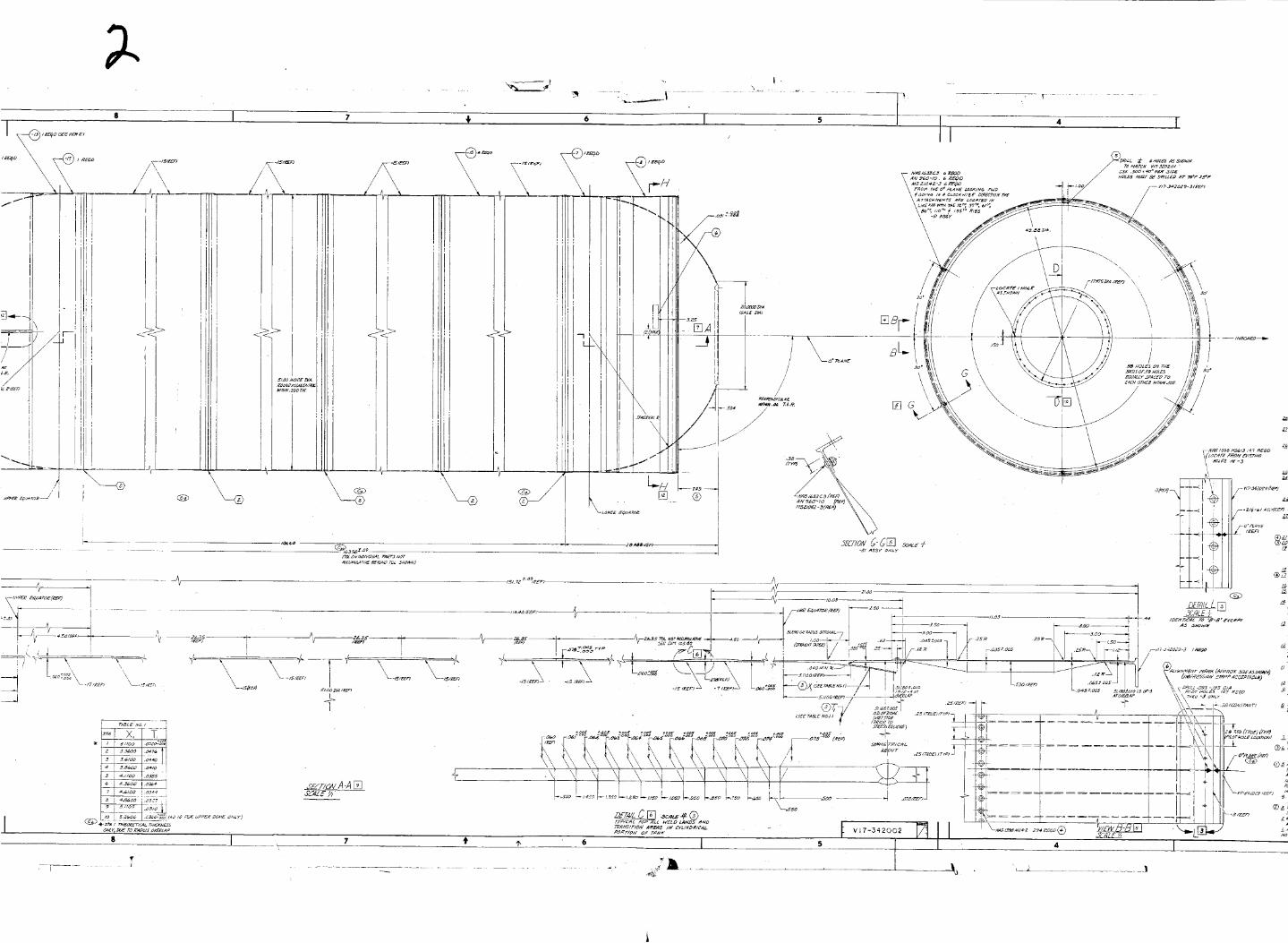
General
There are six SPS tanks (two each of three types). They are
designed for storage of fuel_ oxidizer_ and pressurant. The
fuel and oxidizer tanks are domed cylinders; the pressurant tanks
are spheres. An over-all view of these tanks is found in drawing
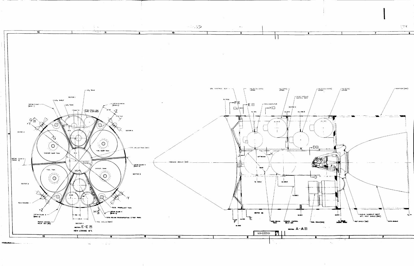
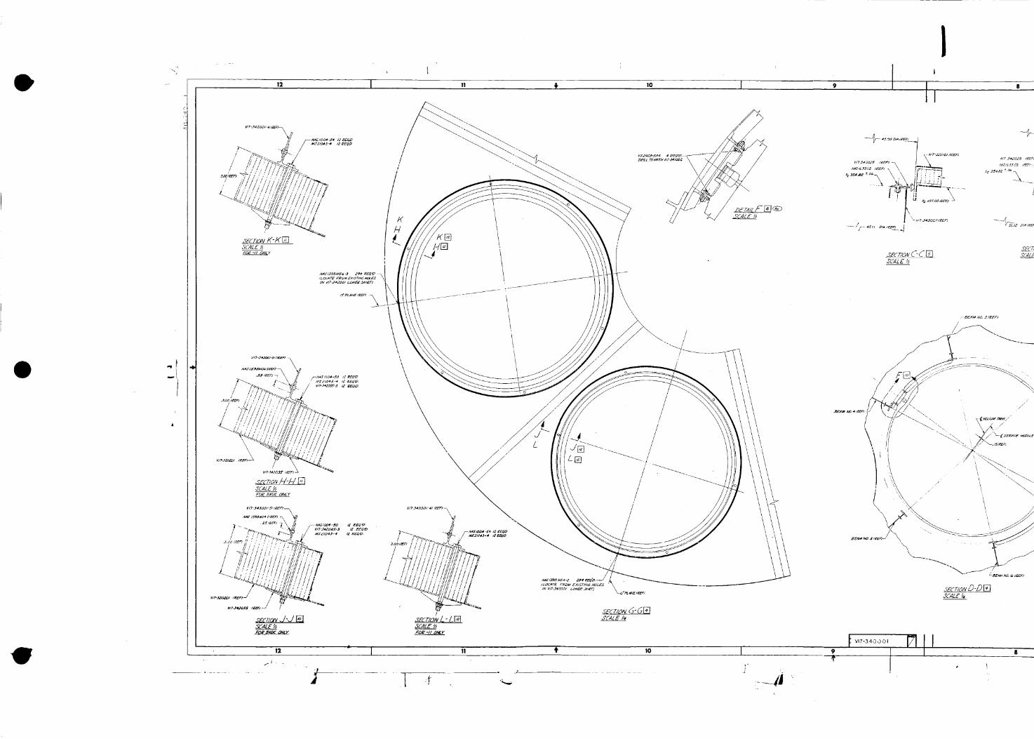
V!7-340001 (Figure 4-1).
The SPS tamks are the only major subcontracted items. Allison_
!nd is_apo!is_ Indiana is fabricating the fuel and oxidizer tanks.
Airite_ Los Amgeles_ California is m_king the pressurant tanks.
All three pairs of tanks are constructed of titanium, alloy
(6AI-4V). NAA drawings (See 4.2.1 and 2 below) are used to
coordinate and control fabrication processes.
Actual installation of these tamks in the S/M will be governed by
Process Specification MA 0310-0007, dated 4 March 1963_ and
entitled "Fitting and Installation of Apollo SPS Tanks."
Configuration and Function
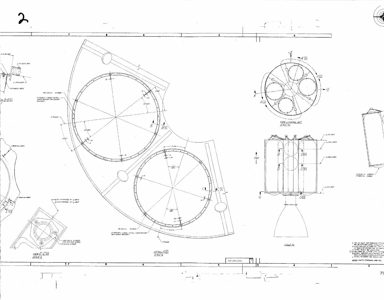
Drawing V17-342001 (Figure 4-2) describes the main oxidizer tank
assembly, including the door. Drawing V17-343001 (Figure 4-3)
does the same thing for the main fuel tank and its door. Drawings
V17-342002 (Figure 4-4) and V!7-34_002 (Figure 4-5_ depict details
for fabrication of the oxidizer and fuel tanks, respectively.
In the latter two drawings the door is not included.
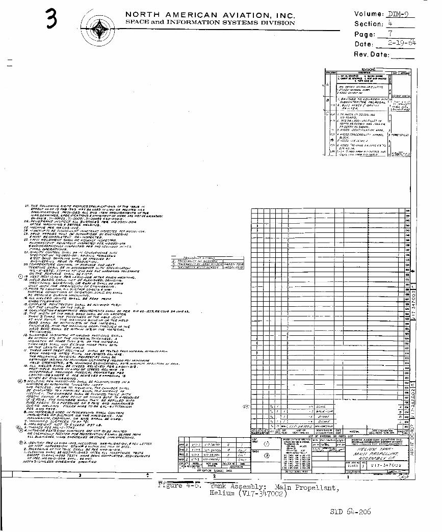
Dra_ng V17-347002 (Figure 4-6) sets forth fabrication details for
the main pressurant tanks.
These six ta__ks of the SPS f1_ction as the storage and provision
vessels for the fuel and oxidizing agent which under pressuriza-
tion feed the main SPS engine.
The approximate outside diameter of each fuel tank is 45 inches;
of each oxidizer tamk_ 51 inches. The lengths of these two tanks
vary between 166 and 165 inches. The diametric difference between
them_ coupled with their almost equal length_ make for dissimilar-
ity in both weight and volumetric capacity. If one omits the
weight of the tank doors and the internal structures, then the
weight of the fuel tank is 230 pounds and of the oxidizer tank,
290 pounds. The volumetric capacity of the fuel tank is 140
cubic feet and Of the oxidizer tank_ 175 cubic feet.
SiD 64-206
-I
J
12 10
I
/
//
!/
/
1o
fl . .
\\\
I 9
mE<rioll O C []SCALE
A
\
\
\
[ Vl7-340001_
%i
I
\/
//
//
//
/
I _7 t _ I
f
4 I
+Z_
- \ I \
;)IX.<_-t --_ ' lill , --
_---__ __ i _
VIE_VLOOKINU AFTUCAL E _o
GF_
/I/
I V17-,.34 O O01 [_]
oF rANK _ rx£ C_V£_ LI_ 0_" SE_V/C
VC_V_ tS#_._Z#O 6 wT._ 4 _ w_3_ _CZ

NORTH AMERICAN AVIATION, INC.SPACE and INFORMATION SYSTEMS DIVISION
Volume: DIM-9
Section: 4
Page: 2
Date: 2-19-64
Rev. Date:
I/.7-347tgDZ Z ,_E_
vA
_E_V/(E MOZPe_E
_ure 4-1.
SCALE ½a
Tv7 _-F£7 7 _4- • _.-......... olu_ of Main Propellant Tank_ Service Module (V17-34000!)
SID 64-206

_Q
\
12 10
12 i0
W7_4_02_
_34202_
• I

I 7 ,I'
I"
Ii 4 I
/
.... A-AE3
I 7 _ 6
/ \
/ \/ \
V/2-J4Z_OZ'_I /,_EqZ_
4 I
L

NORTH AMERICAN AVIATION, INC.SPACE and INFORMATION SYSTEMS DIVISION
Volume: D_vI- 9
Section: 4
Page: 3
Date: 2-19-64
Rev. Date:
4, _A_E_gD_C_V_C_ZZea
C ! ZL_rZED - z/ _gu/_'_r5
r_cE_8/u_ s×_ozs
ENO iTEM .1.
¥ 2
_..OlO =_ TINKASMMBLY- _IN _qC.PELLANT,
'igure k-_. Tank Assembly Complete: h_±_, _ _±_±±_n_ Oxidizer
S!D 64-206

I
10
/
\
\\
\
\
+Y
I Ii
//
/
/
/
/ /
/
///
/
/
,\
\
1
I 3_. 195
-¥
//
I,
i
-_ ..... I_097
,\
"X
v,7-327,o,r;1III i
I
' ,')V H
\
-4
<\
[] /
tl',,lol,_z _',_,.IA.,I ,¢'_
II
/
I

NORTH AMERICAN AVIATION, INC.
SPACE and INFORMATION SYSTEMS DIVISION
Volume:
Section:
Page:
Date:
Rev. Date:
DIM-?
518
2-19-64
_i REWS!ONS
21_NN_T 8_RB_O_E_ 4 _ SHOP_T_EP_ _ OK
• _DDZ'_ _,_z_ -7 z
.......I..... I
APPLICATION(USAGE) OATA _ DO NOT SCALEPRINT
Figure 5-16. Installation of Engine Mount;
Service Propulsion System (V17-327101-I)
T_S-_ 64-206

•-_i_. -.'- ...........
12
>io. / z_/ls:zE::
,,_ 41_"
i I0
_./3S (rvPj
I
3_ I_P_
DET//L J []
SC.4LE
/
• /.--
" _/ I
30 _AO _zA
g'._o'J
SPEC:_CD _'Y -'_-
NO SC.#L_
_2D . z_
L
- ---C ___L
2dALE _/_
1s 44500 _sz_7 '_.7000 _o_t:
\\,
//
//
/
//
/
!! 1
: ,,;
/'
I
_ I_ II0
/
J
f
///
/
I 9
\ /\
I :' , I I
! \ \
L o_o::°#f \ '\
/
I
i 6 I
_4 _z_
\
>
I
i -
I ........+
I
&I
?_eLz lvo i
N i 4.8_00 1.0_27 I
(N)
i
ms:riu_A-A[]J(A L &- I/1"
7 i 6 I s
__1
I
k
NORTH AMERICAN AVIATION, INC.SPACE and INFORMATION SYSTEMS DIVISION
Volume: DIM- 9
Section: 4
Page: 5
Date: 2-19-64
Rev. Date:
_Z_D_D _/NI_ _aa _E _'eZE :eo_ sm_Elrr_s_ r, AS
i T
STD 64-_o6

i
i
i
12 I 11 + Io I 9
Q° PLANE .a5 ._,L/O*_YN -+. 25
I
/V
/
3_CT/ONIV-IV []SCALE ½
II
,bEALE i_
tVI7-343002 M
,l I ', " t ,o I

I
I
+
6
w
I
\
// °\
/
1 ::'
3NORTH AMERICAN AVIATION, INC.SPACE and INFORMATION SYSTEMS DIVISION
rR_j_y J__Ls
_/_ _=r,4z E¸ Z0_E _" Z,9_.."_._ _D
(?0 ¢_-,,-* j
Volume: DIM-9
Section: 4
Page: 6
Date: 2-19-64
Rev. Date:
Figure 4-5. Tank Assembly: Main Propellant_ Fuel (V17-343002)
SI:D 64-2o6
/
iE"
"h
12
-I
T .
I 11
I
lO
5:Azt / /
12 I 11 lO I 9
-_ 7.L
--4-2.77 _
//\
\
--4 t
J_ _ 17_-3_7Q_
i
NORTH AMERICAN AVIATION, INC.SPACE and INFORMATION SYSTEMS DIVISION
Volume: DIM-9
Section: 4
Page: 7
Date: 2-19-64
Rev. Date:
I
4-.-+--
+---+--
+--.+.-
I Im
I I_r_
I I o_
I I o1_
I I OlS
I I o14
I J ola
LIST OF MATERIAL OR PARTS LIST
oo No_ SCULl FRN_
t
Tank Assembly: Main PropellantHelium (V17-3¢7002) "
s_D 64-2o6
NORTH AMERICAN AVIATION, INC.SPACE and INFORMATION SYSTEMS DIVISION
Volume: D]_4- 9
Section: 4
Page:
Date: 2-19-64
Rev. Date:
4.2.5
4.2.6
4.3.2
4.4.2
4.5.2
The weight and volume capacity of each pressurant tank are 390
pounds and 19 cubic feet, respectively. The outside diameterof each is about 41 inches.
Drawing V17-342025, "Assembly of Upper Skirt Support, Oxidizer
Tank"_igure 4-7), presents typical support details of these
large oxidizer and fuel tanks at the forward bulkhead. Support
details for these same tanks at the aft bulkhead are found in
Figures 2-10 through 2-13.
Operatin_ Conditions
In a normal launch mission, the SPS tanks will store (without
loss of contents) and supply under pressure the necessary fuel
and oxidizing agent to the SPS engine for all maneuvers between
transpositional docking and earth trajectory. A temperaturerange of 40-80 F will be maintained.
In a launch abort mission, the SPS tanks will provide sufficient
fuel and oxidizer under necessary pressure to enable SPS engine
operation for bringing the C/M successfully into earth reentry.
Design Characteristics and Criteria
Criteria useful in design of SPS components of tank structures
may be found in ARM-6.
The environmental requirements listed for the S/M in 2.4.1 are
equally valid for the SPS tank structures.
Test Rezuirements
Test requirements for the SPS tank structures are stated in
SID 62-109-2, "General Test Plan, Research and Development for
Project Apollo Spacecraft - Individual System Test."
Tests already completed and covered by released ATR's are these:
ATR NO. NAME OF TEST
301-4
301-8
301-13
302-1
3o5
Static Test of Tank Skirt
SPS Main Propellant Tank Cover Door
Seal Test - S/M, Main PropellantManhole Door
Pressure Vessel Tests - S/M
Pressurant and Propellant Tanks
S/M Fuel and Oxidizer Tank
Fastener Tests
SID 64-206
41
_cr A-AI_
NORTH AMERICAN AVIATION, INC.SPACE and INFORMATION SYSTEMS DIVISION
Volume: DIM-9
Section: 4
Page: 9
Date: 2-19-64
Rev. Date:
_*OPED IKT_/Nf I_r CODIN6_ _asr*c_ r-H._
/
/
/
/
/
/
I
Figure 4-7. Assembly of Upper Skirt Support, Oxidizer Tank (V!7-342025)
SID 64-206

NORTH AMERICAN AVIATION, INC.SPACE and INFORMATION SYSTEMS DIVISION
Volume: DIM-9
Section: 4
Page: i0
Date: __79_64
IRev. Date:
4.5.3 Particular fabrication test requirements for the subcontractors
of the SPS tanks are called out in SID 62-1259 (reissued 12
February 1963), "Statement of Work for Testing of Pressurant
and Propellant Tanks_ Project Apollo."
SiD 64.-206
NORTH AMERICAN AVIATION, INC.SPACE and INFORMATION SYSTEMS DIVISION
Volume: DIM-9
Section: 5
Page: i
Date: ___Rev. Date:
5.0
5.1
5.1.i
5.1.2
5.1.3
5.2.2
5.2.3
5.2.4
SYSTEMS MOUNTING PROVISIONS
General
Mounting provisions (or support structures) are a requirement for
the following systems:
a. Environmental control system
b. Reaction control system
c. Service propulsion system
d. Electrical power system
e. Telecommunication system
The subject matter of this section of DIM- 9 is confined to con-
figuration details supported by drawings.
The function of systems-support structures is self-explanatory.Any variables in the treatment of the environmental requirements
other than those found in 2.4.1 will be stated. Again, operating
conditions for these mounting provisions differ in no way from
the conditions imposed on the structures supported by them. Like-
wise, design characteristics and criteria for component configura-
tion are also given in ARM-6. Finally_ only one test requirement
exists for the testing of systems-mounting provisions. It is
ATR 301-i1, "Fittings and Equipment Support," and it is yet
unwritten, pending completion o£ test.
ECS Mounting Provisions Configuration
Drawing V17-331717, "Mounting Provisions, Environmental Control
Systems Installations" (Figures 5-i through 5-3) shows configura-
tion details for supporting structures of this system.
Particular details concerning the L02 supercritical storage bot-
tles are found in drawing V!7-33!667, "Assembly of Oxygen Tank
Shelf Support" (Figure 5-4).
which special support structures need design. The drawings forthese are in preparation.
Valving and hard line supports in the ECS are mounted by means of
brackets, often of special design.
RCS Mounting Provisions Configuration
Drawing V!7-332000, "Module Installation of Reaction Control
System" (Figure 5-5), and drawing V17-332001_ "Panel Assembly
S!D 64-206
_I.F./-I ¸ ,-- - .........
12
!1
I 11 t lO
mEW J-J_
l
\\
/J(_,,,_-_._
L_
i
I I ,
_LPG_t-I-_O-_lOi 4. llOD
1
_0LES IN LINE - 8PLFIC_S _v_1-_15c._- I:1
1
I)
i
i
11.115o
j____ J !

NORTH AMERICAN AVIATION, INC.SPACE and INFORMATION SYSTEMS DIVISION
_ /--_EEOET_,LF [] _ ........ ao (REF>
----/ , \\,\ /// _ \ \
r,.ooo).....G
\
5_'lllCHIMi" !ILIjSH AFT[I_
fl 5'rliLLIl I"ION (TYP)
vi'i-a_o2a_(i_Rr)
,_-c_
\ .---_-_<\ /__ I
,\ , II xV< '_<'_ /I\\\ I"/Ik<_'k<"_"_"'">\\\ /;-.._ !
I / \ /
IIIIII
Ii_Gol I 5C#_LE ;/l_
_,._1 iI!i / /i"L-_-J
t v'"" ''" l'qtl
I I I
i
, t
t_J_ IV_Ay B_ _UI_CI4A%I._) i-ROi#_ _itiC.iC Iv_FG CO
LOS At_Gi.Li.% , C_L_F
• ITEM TO _ P1QUNTED ON F#tRSID£ OF BHD ,,_3".O
I. IHSTRLL RI'JI£T5 PER MROIOI-OO_
NOTES: u_L_ssorH_w,a_ ltP£GIllll_
$ IVl'1"331586) VI1-331581[
I Vlq-331510
i_ VI1-531571-11
I V11-331570 -II
Vll- 3315e_9 -Li
I Vi7-3315¢_4. -_
I ",./1"1-3515¢_5 -_1 _r,_ _vI]-331"I1_
Volume: DIM- 9
Section: 5
Page: 2
Date: 2-19-64
Rev. Date:
$i I
I I I , I t,-, _-..-.,--I 1" <"t '__'1_1 I'_-_ I Vn-<_>" '_ I - izJ/_',.,. P""I /
t r i" /-vl'l- : Vll-_ll! _ - _lu.*.l_ *ll,
"_.... _ .... / tl = i',:i-i,/If'ION li I)MA / / llllCm'lll_T /
_ "_ o- E_ ...... _°_ ControlFigure 5-_. M_untz-o Provisions_ .................
System Imsta!lations (\T17-331717-I)
I
IG c
NO_ITM AMIIICAN AVIATIOn, IN_ ,
i_iOUNTING PROVISIONS-
COI_PONENT_ I_HD 355.01
ASSY OF
'-IFIn,t_,: VI7-331717
SID 64-206

P_.4 23 222O
\
\
\
?-4 _3 22
\
\
L

I 17 / I I 16
I
\
NORTH AMERICAN AVIATION, INC.SPACE and INFORMATION SYSTEMS DIVISION
ROTF}TED @(_" Cw
i Nit .....- [_ V]7-33171 VIEw LOOKI_,'I_PTON .SECTC)RT[ BI,,E)_I..,_'.0 -
_ ' __L_ ' _ - ! ! Figure 5-2. Mount ing Provi sion s, Environment al
System Installations (V17-331717-2)
Volume: DiM-ip__
Section: 5
Page: 3
Date: 2-19-64
Rev. Date:
_VSK_S
, _E_3-- --
FOR L/M, U/B #r G/N SEE SH,
Control
S!D 64-206

36 35 34 33
\
\
\
l //¸
\
\\
\
,mD.,..
36
/
//
\ \\
\
VIEW LOOKING /_FT ON
SECTOR _ E_HD 355.0
35 t 34 I 33

3_
32
31 3o I 8.9
\\ \
\
\
/
2_
\
\
\
NORTH AMERICAN AVIATION, INC.SPACE and INFORMATION SYSTEMS DIVISION
Volume: DIM-9
Section: 5
Page: 4
Date: 2-19-64
Rev. Date:
FOR L/M,G/N¢ _ SEESHt
F,='FI,,,,-=,,,,
Figure 5-3. Mounting Provisions, Environmental Control
System Installations (V17-331717-3)
S_D 54-205
12
i
I
I
L
8 ] 7 !_ 6
\
'\
/ ./
/
//

L
\\ \
'\
\
\
\\
B
I- mZS:ooo5 DIA<EX_fv HOLES rHRU TO _IA-rcH Vln-92OOO_
v_9I_2O2O3-7 _n R_Dc_. 757-3-4 94. _'EQ D
,' _5
L_C ./....... A-A []
r_:) \ oso SrodK (r::_
: _\ ,,\,_ '-- O5-0 3rOCK ('r_P)
.... C-C_!SCALE _/i
NORTH AMERICAN AVIATION, INC.SPACE and INFORMATION SYSTEMS DIVISION
.......B-d []SCmZE ///
sr_o
o\
Volume: DIM-9
Section: 5
Page: 5
Date: 2-19-_4
Rev. Date:
F_ oU .... Assembly _+_ n...... Tank _=_o
Support (%U7-331667)
SID 64-206
I
12 I
I
la I
%lO I 9 I 7 ,If 6
_ I
]_ECTION E-E []
]--,'/_ 1
6E¢ T/O# D-D []
J
¢5ECF/O_ C-C []
_c'A _ 4t ' --'p I
8ECT/OM _-_ []
E-I
©
I ¢.ooo_!
4
I 5
[]
NORTH AMERICAN AVIATION, INC.SPACE and INFORMATTON SYSTEMS DTVTSTON
Vo I um e: D_V_-_9___
Section:5
Page: 6
Date: 2-19-64
Rev. Date:
I
>/-
I
REVISIONS
s _DO X_T Z_
_I _
I
I
I
!--
SID 64-206
NORTH AMERICAN AVIATION, INC.SPACE and INFORMATION SYSTEMS DIVISION
Volume: D!M-9 ._
Section: 5
Page: 7
Date: 2-19-64
Rev. Date:
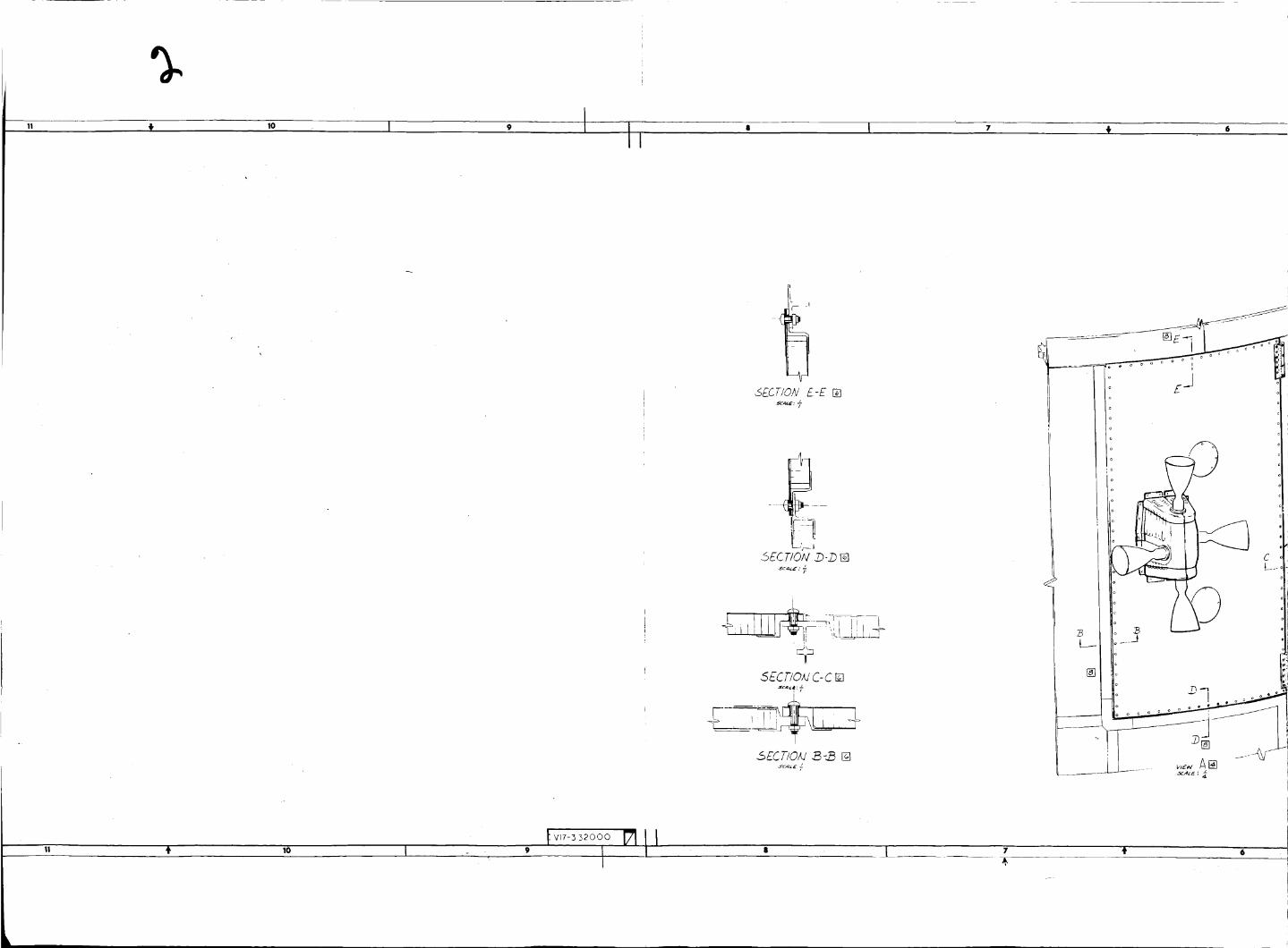
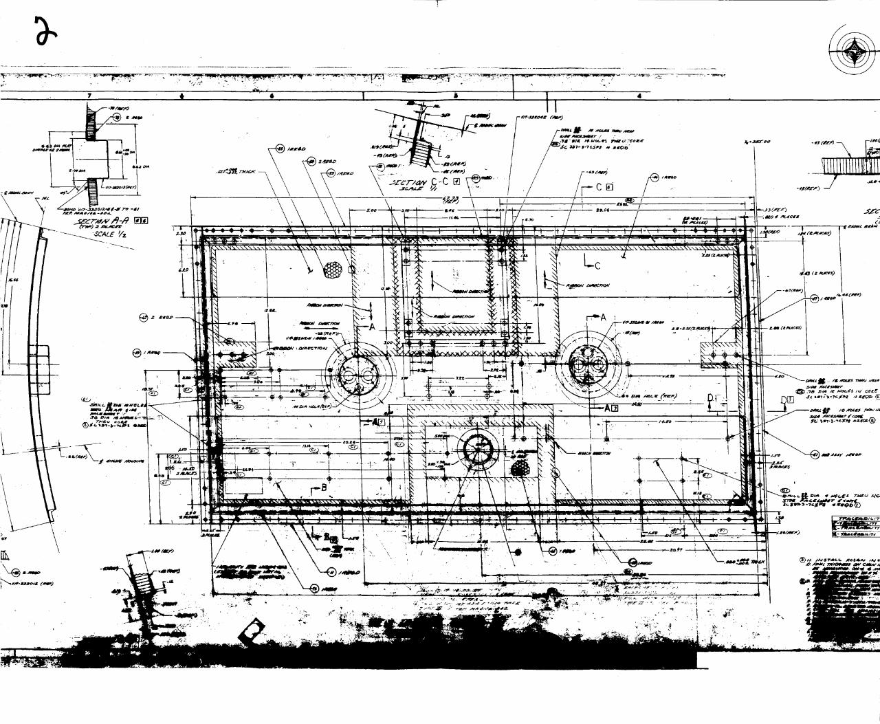
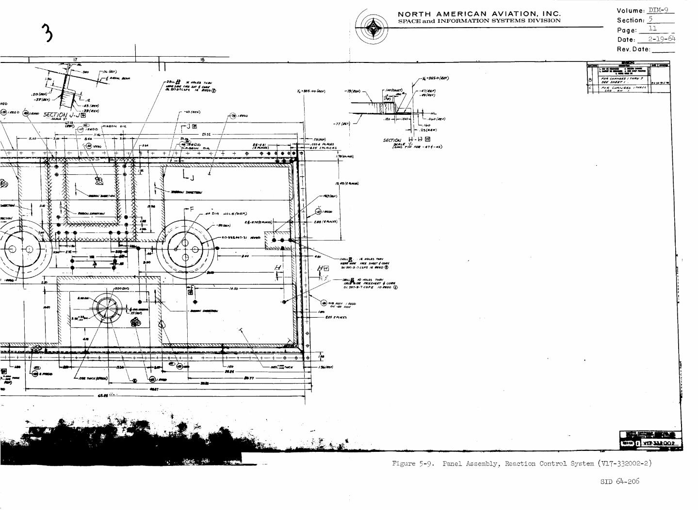
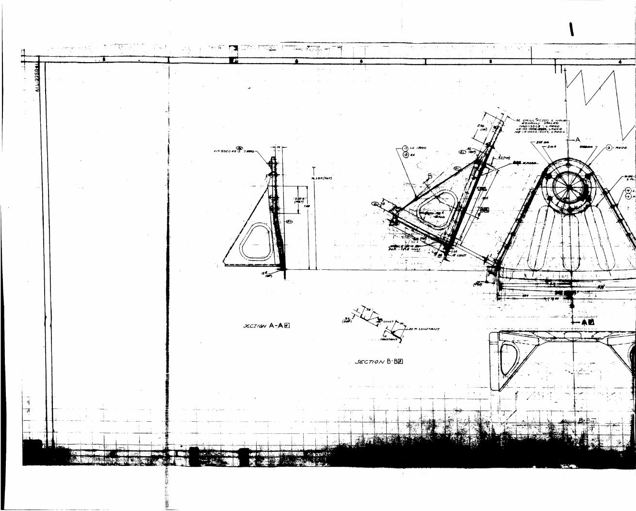
5.3.2
5.3.3
5.3.4
5.3.5
5.3.6
5.3.7
5.4
5.4.1
5.4.3
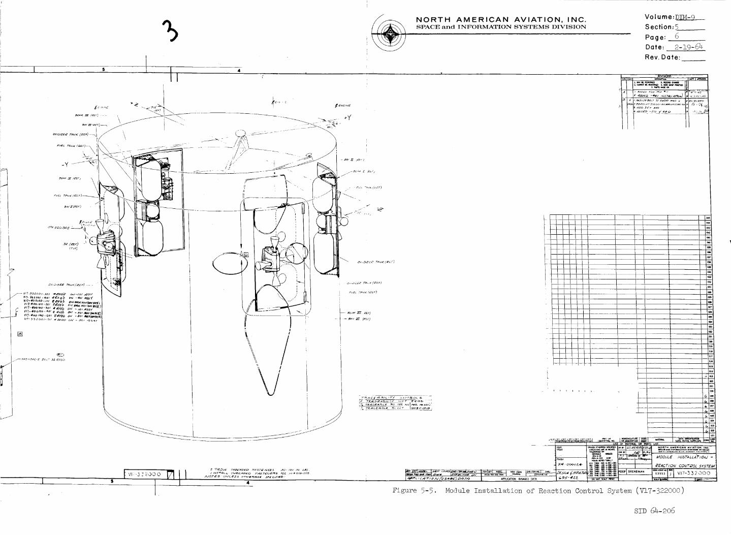
Complete Reaction Control System" (Figures 5-6 through 5-7) show
the over-all configuration o£ the RCS mounting provisions.
Drawing _±7-332002 (Figures 5-8 through 5-9) gives details of the
panel per se.
The housing assembly of the RCS is shown in drawing V!7-332010
(Figure 5-10). Brackets are used for mounting the assembly.
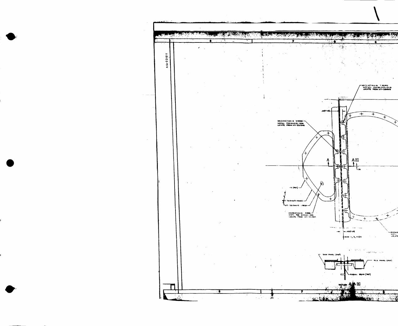
The engines of the RCS are supported on panels which form part
of the outer shell of the S/H. Hinges, attached by screws to
the shell, allow the RCS panels to be swung out for access or
replacement.
Heat shields which protect the outer shell of the S/H from RCS-
engine-flame impingement are shown, with their mountings, in
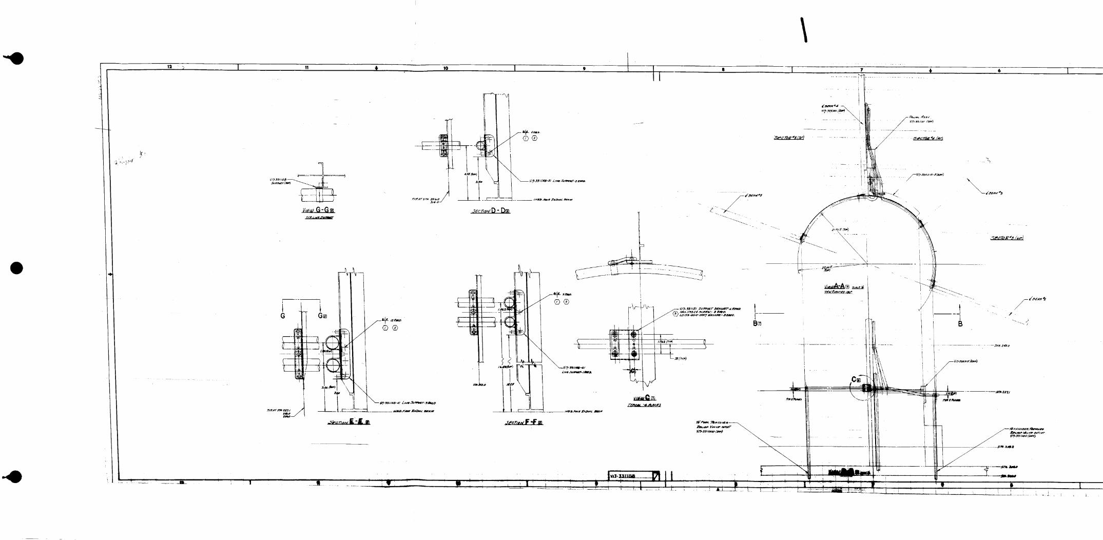
two drawings: V17-331525 (Figure 5-11) for the longitudinal
installation, and V17-331611 (Figure 5-12) for the lateral
installation. The insulation for the RCS panels is depicted in
drawing V!7-332046 (Figure 5-13).
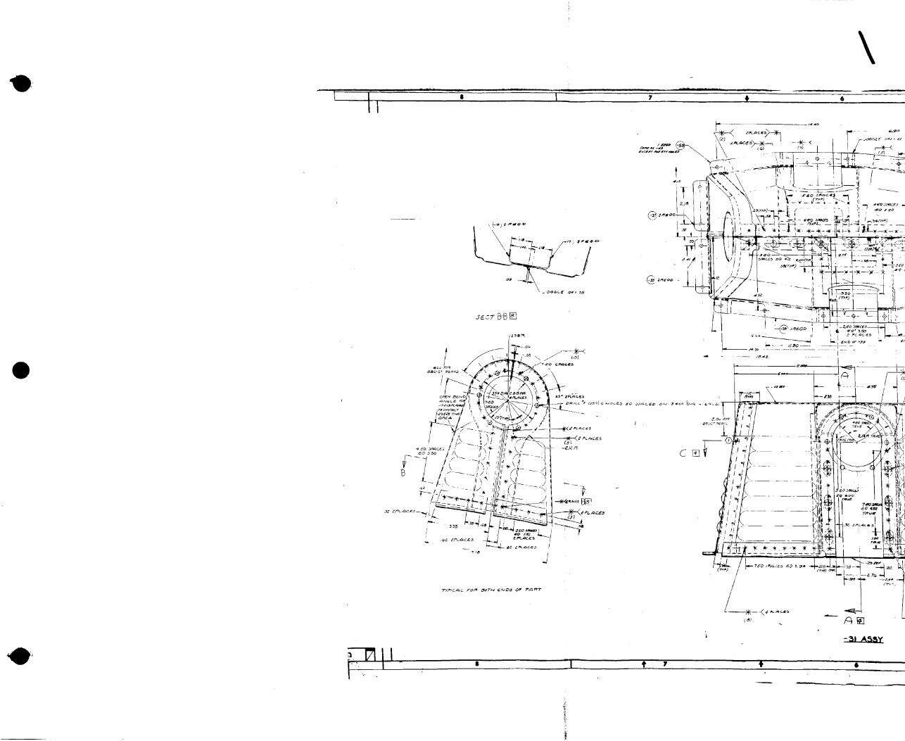
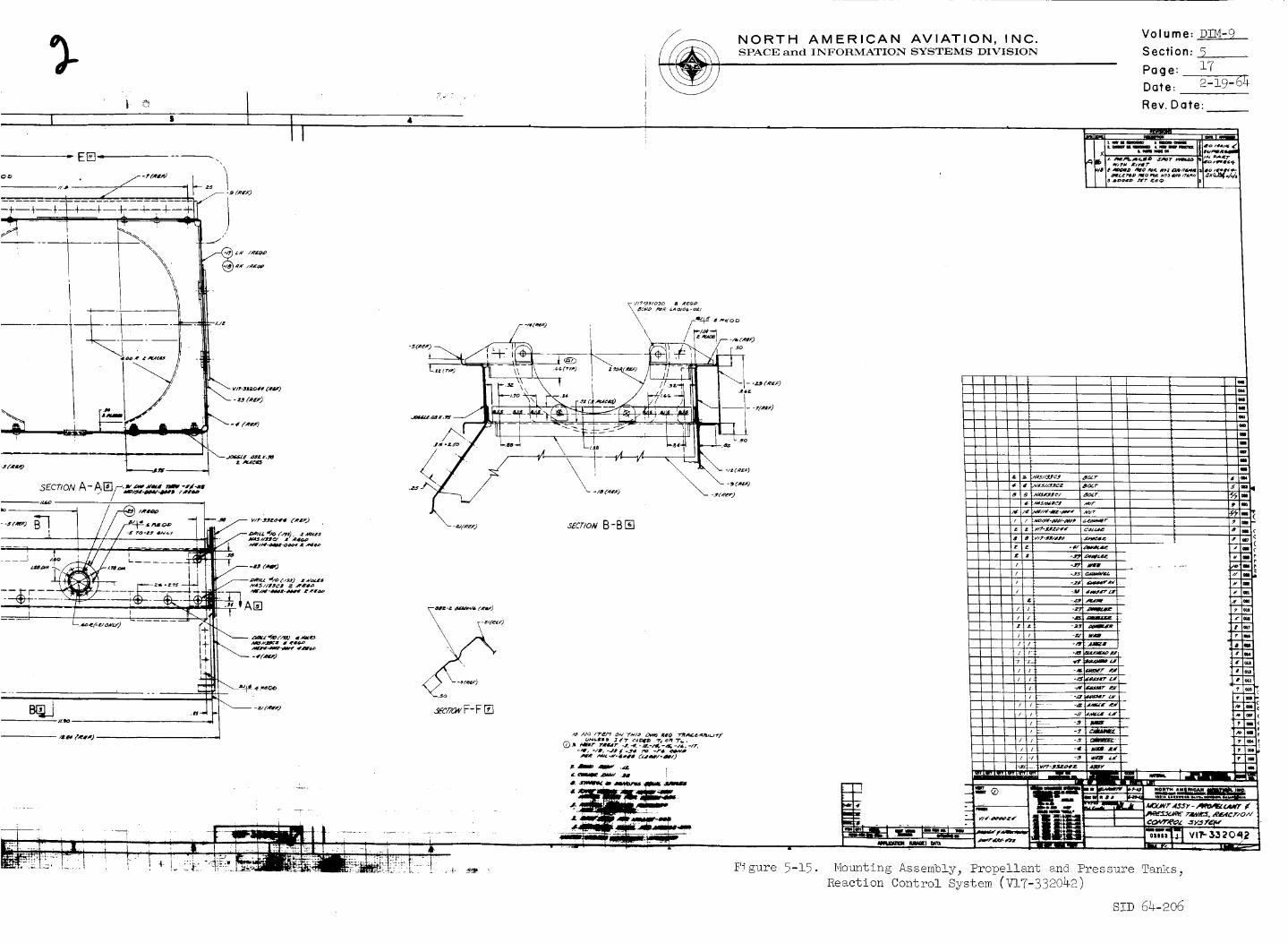
The RCS engine installation requires a cluster of three tanks in
each of its four locations. The complete assembly of the fuel,
oxidizer, and pressurant tanks which are mounted as a cluster is
exhibited in drawings V!7-332041 (Figure 5-14) and V17-332042
(Figure 5-15).
Mounting of valves for the RCS is done by brackets and a panel.
Mounting of the RCS control unit has not been designed yet.
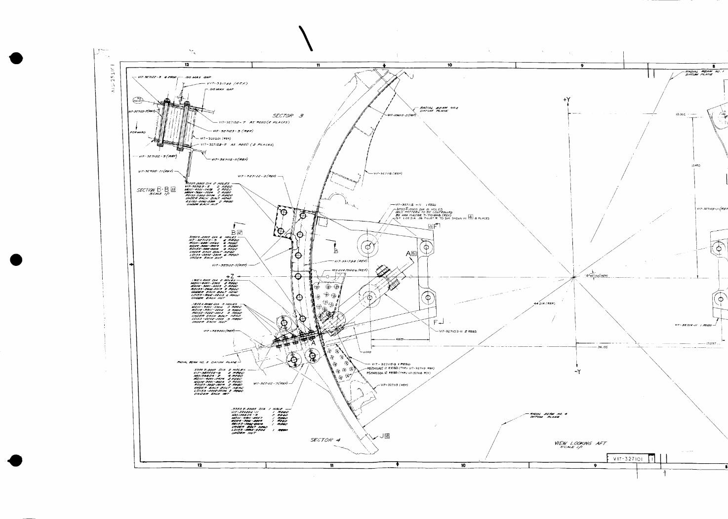
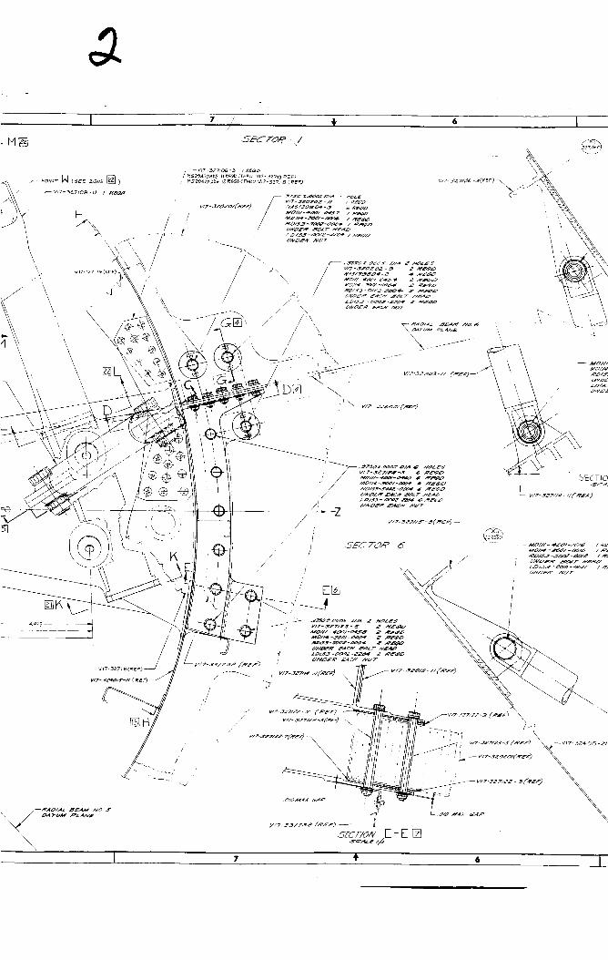
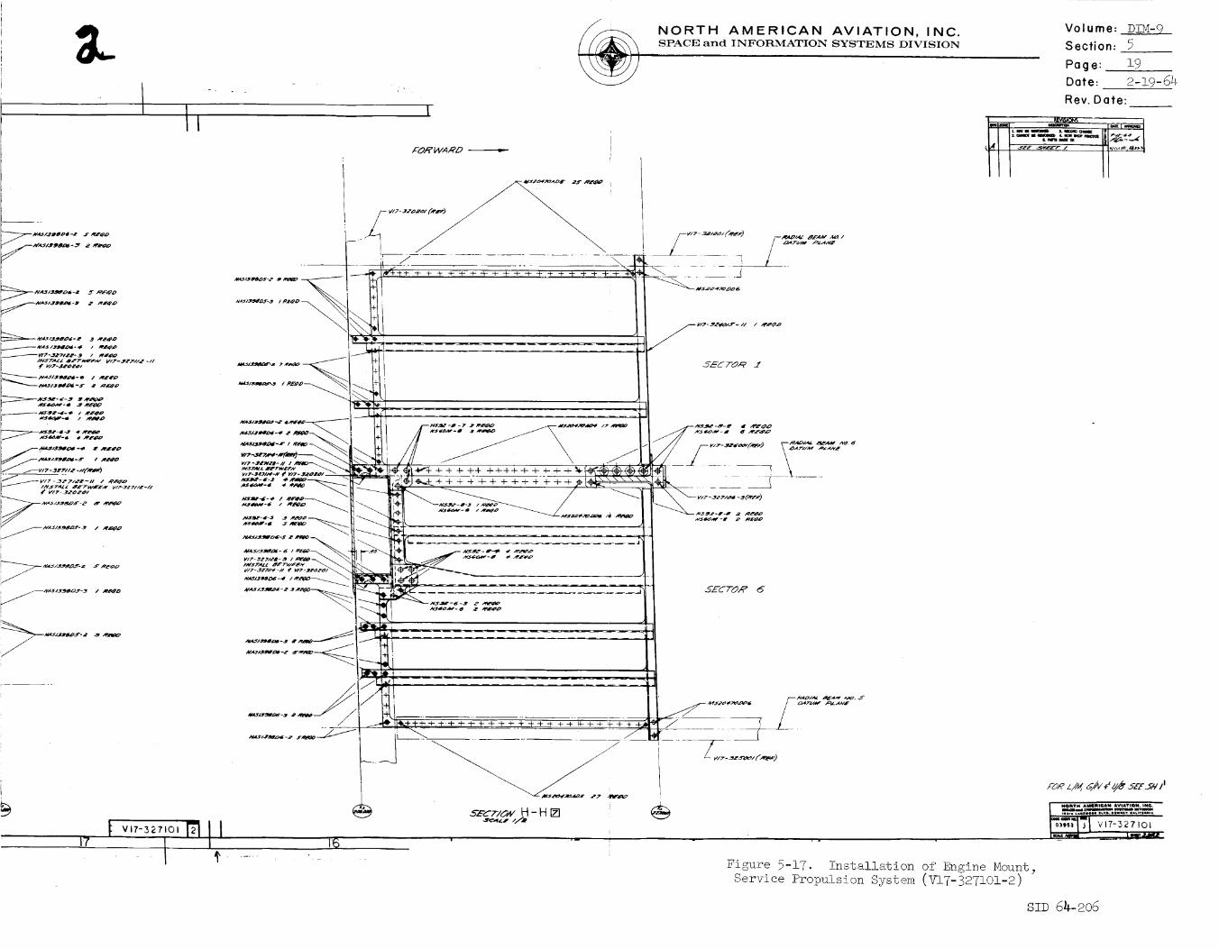
SPS Mountin_ Provisions Configuration
Drawing V17-327101, "Installation of Engine Mount, Service
Propulsion System" (Figures 5-16 through 5-17), breaks down the
mounting provisions for the SPS main engine.
A propellant distribution system of valving, hard lines; and
electrical harnesses carry fuel and electricity to the SPS main
engine. Drawing V!7-33!000 (Figure 5-18) depicts mounting pro-
visions for this distribution system.
Support provisions for the pressurization system which assures aconstant flow of fuel and oxidizer to the main engine are shown
in drawing V17-331!00 (Figure 5-19). Included in these pro-
visions are a control panel, line supports, and mounting brackets.
Drawings V!7-33!I01 and V17-331102 which exhibit supports for
the panel assembly of the pressurization-system module are not
available and therefore not included.
SID 64-206

\
.
12 I 11 Io
kL/lllllllllilllllllllllllllllllllllllllilllllII
I
ZCC7 Z_-D_
12 !0 ) v,7-_2oo,71 !) II

* I 7 t 6 I sII
\
I
iN 5.*--.__.5
NORTH AMERICAN AVIATION, INC.SPACE and INFORMATION SYSTEMS DIVISION
Volume: DIM-9
Section: 5 ,.
Page: 8
Date: 2-19-64
Flev.Date:
\\\\\\\\\.........
' l-l-i
i_ I I -ILI4 "/_AI_7"J AP..L_.g'O
I
7
I
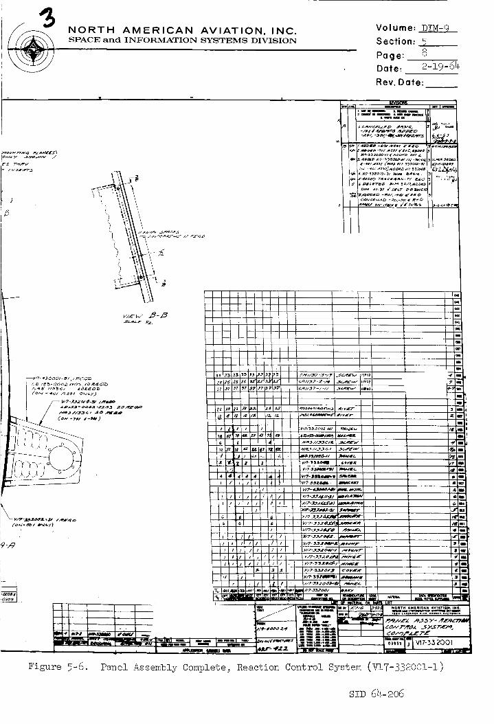
Figure 5-6. Panel Assembly Complete, Reaction Control System (V!7-33200!-!)
SY_ 64-206

i
_ v_7-332ooi

19 ,!, 18 I i7 I '-_II
/;;"
,v,>,,2o.,,.,.<<_ t t,,_".............° ....°: l ;"°'°'Z
VI_I I. _ 4_)_,l_llwi _'_ _o__,1_
19 16 fv,_>_o7 nilI

NORTH AMERICAN AVIATION, INC,SPACE and INFORMATION SYSTEMS DIVISION
Volume: DIM-9
Section: 5
9Page:Date: 2-19-64
Rev. Date:
mini _ iiii I A_llm_. M ii mllnm L Ilnl {lall
[_] fo.¢ C,_A,qGEX / r#_ev
i ...¢c_" ._NEgr i
7
I÷_÷ ,'1
b
k
I
Figure 5-7. Panel Assembly Complete, Reaction Control System (V17-332001-2)
SID 64-206

II
t
I .
@
m I
y/?-J20oo/
,JTJO
G_
I t---P---q---I _ i _
i ,iI ., II
f' II _:
\
I •
\
I I I -\_
\\
• I
/
L
Yl_W ZOb/(IN6 IWJhT _/,"" ._m_.m _q_
_ ,._cr_ot¢E-E lSl
5NORTH AMERICAN AVIATION, INC.SPACE and INFORMATION SYSTEMS DIVISION
.... ]
3
. zJ (_.e, r)
's;_ D :D []
®
Volume: DIM-9_
Section: 5
Page: 10
Date: 2-19 .64
Rev. Date:
=
J
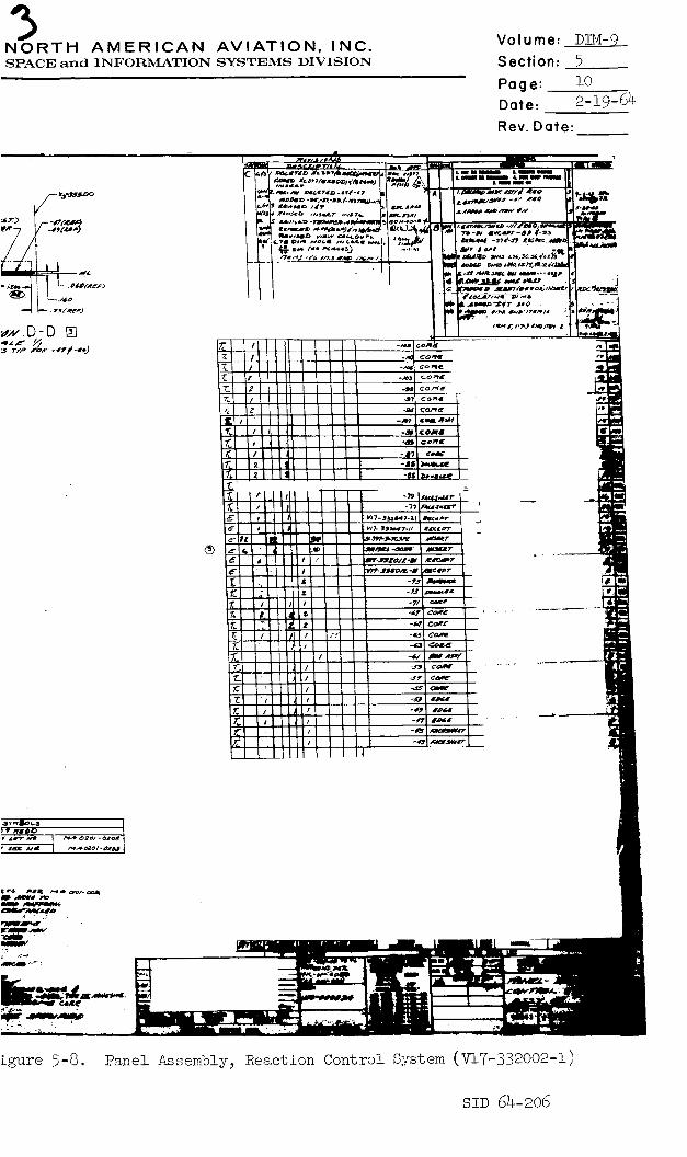
Lgure 5-8. _anel Assemb!y, Reaction Control System (V!7-332002-I)
szz) 64-2o6
24 l
i
I

22 I 21
-I- 4-
-- f$,_ //
I / //. t._"
\\\
@(m,77
/
t -_ -t- ÷
_r.,q.5o
÷ +
\\\
\\
/
\ \!
20
+
+
4
ff
4
18
\\ \
I
I
Lj -/
NORTH AMFRICAN AVIATION, INC.SPACI_, and INFOI:_MATION SYSTEMS DIVISION
Volume: DIM-9
Section: 5
Page: ii
Date: 2-19-6_
Rev. Date:
I I I_ m'_m'm _m_,*_ I11 II I I"'" "_L'--'" llI
_l l ...... II
I_ • _ / ...\ \ k._l _=.
• I
' ih::
SID 64-206
I 7 4' 6
\
/
_, /:/9 ) 2 _ _r _ _
J_CT BB[]
C
8 7

I , 5
fNORTH AMERICAN AVIATION, INC.SPACE and INFORMATION SYSTEMS DIVISION
1
I\
!Ii
Figure 5-!0.
Volume: DIM-9 _
Section: 5
12Page:
Date: 2-19-64
Rev. Date:
m
t l_."£'L"L._:%'"........r//,, .....<........
:?,t:1;'_2:2.......
"'UI
(:: ,* - .o)
.....
I __ I
I
I
I
1 " ;+_ O"Hoasm. o Assembly, Reaction Control System (V17-332010)
SZD 64-206

\Io
iii¢$
DETAILD []_AUE: I//2
SECTIONG-G []SCALE:
(_)
DETAIL C[_]
SCALE: I/_
C ,.,,,°°,++| ,:-+'-..,,",+°
SECTIONd-d []
• SCAL£: I/I
/_ _eD oH -2/
+

I -- 5
NORTH AMERICAN AVIATION, INC.SPACE and INFORMATION SYSTEMS DIVISION
+Z-Z
+Y-y
IVI#-J.II_I_I9
Volume: DIM-9
Section: 5
Page: 13
Dote: 2-:]_9-64
Rev. Dote:
LII
I,m I I_
_#.rl
Figure 5-ii. Longitudinal Heat Shield Installation;Reaction Control System (V17-331525)
SiD 64-206
\
i
i
i
b.
M62_4Z'll_4-+ "t REOtD
Ubr._'CB. tqU3t4 vt'_,-3nlNmo_
.| I i,
.; • -1 +. - u
• " _,,,._t_ .• .... _ :. .-_._::_._,_._:_, : .::..,.:-_. , .... .

.... , , i *--= inl , , ii i i i
..... "' ....._"...... .' _ *, ....... ! IT _. '",*_ .....'
:... .
.[
-- @l,_'l
//+/
j.?\._
t
NORTH AMERICAN AVIATION, INC.SPACE and INFORMATION SYSTEMS DIVISION
\'\ /z , .
• ".......""> "_'" J_-Li+_L'--x_L__B,_] ....... :..............
......B-B_
.. ...;..._:' !,;j.,
I
i
I
• . . • .
NOTE5: UNLE_ OTW_RW;_ _P_CI_EO
Figure 5-!2. Lateral Heat Shield Installation,
Reaction Control System (V17-331611)
• ' I
SID 64-206

\
'12 ____t__ lo ii
-- 3Z#0.
,_4¢, -- ---
-_--I
--32 9/ --
J300
I
2_
q--
, y ]
II,0_ _xl - 17 o_LV
....
S,12 J
Ll
i ,
\ I
I-! i
li \ II Vt.7.'3320 ____
I

NORTH AMERICAN AVIATION, INC.SPACE and INFORMATION SYSTEMS DIVISION
Volume: DIM-9 _
Section: 5
Page: i_
Date: 2-19-64
Rev. Date:
\\
/
!
Figure 5-!3. Insulation Installation for Reaction
Control System (V17-332046)
SID 64-206
l
7
.g
!;
7 ........ :-- !-.
- ii t _ . I
i
_t:2
1
-!
I_,
l
L
-!f_-7 .....I \:d
. I '!|
t

NORTH AMERICAN AVIATION, INC.SPACE and INFORMATION SYSTEMS DIVISION
II i I
d
_....t _
. h
i!
-e
i
Volume: DIM- 9
Section: 5
Page: 16
Date: 2-19-64
Rev. Date:
L'U_'=._._'__
_:.___
L

I
12 I
SECT/O#J-J []
m°°l/ / r-_
/
--,-,-_-_tl -_" "%.. ! _---
_.,
vIEWD-D []
• .. ..
!o I
\
t
view C []
! i
I
\
I
DE]|
NORTH AMERICAN AVIATION, INC.SPACE and INFORMATION SYSTEMS DIVISION
Volume: D!M-9
Section: 5
Page: 17
Date: 2-19-64
Rev. Date:
I I PI __
v/¢_3_lOao ii _o#
-zlm_,,') 3EC7"IONB-g [] _- _'<"+*-')
,_CTZ_F-F []
_F
_F.
_F
_r
.#zz..,#_
w_
A_E
I
I
I
!
i
Mounting Assembly_ Propellant and Pressure Tanks_
Reaction Control System (V!7-332042)
SiD 64-206
'1
<
t2 1o
,//;
///
/
\\
\
\
\\
\\,
/
/
//
I
\\\
\\
\
//
\
//
//
//
!
I
\
/
/
.¥
//
/.....,_?
134&3
//
\
\\
\\
I g'
.H_
/\\\\
\

II
'\
\\
M_ II/- -I_1-1018 I _¢2_
/
/
_'\ /'
G'-,%
SECT,0NA- AX -_CALZ=
. , Iv'7-327'_°'_ II1 ¢
NORTH AMERICAN AVIATION, INC.SPACE aBd INFORMATION SYSTEMS DIVISION
Volume: DIH-__
Section: 5
Page: 18
Date: 2-19 -64
Rev. Date:
_. REVISIONS II
WEO,_AW-V v/irw _,vAl/_5
,_ z_l.,_z. S,VEE T _ ,,,
L
_c_ ON
APPLICATION (USAGEI DATA
Figure 5-16. installation of Engine Hount_
Service Propulsion System (V17-327101-1)
SID 64-206

"'1 r--'O_/LL LoTs- O/A I
5EcT/_w M-M []-_CAZ E///
N
N
N
SECT�ON N-N _'_._"c._. E ///
5scr/ow L- L [],_zE //#
P_4 23
I
-..,-------- ,c'ORWARD
:_-CT/OW K- K []
21 20 __ I
/N_. T,4L_ atT_e'_"A/ V.'7--3Z711_ -/I
w_ -ae_,'/_-,','(_,-)
17
NORTH AMERICAN AVIATION, INC.SPAC]_ and II_!FOI_MATIOI_T SYSTEMS DTVISTON
A'OA_"I,,VAA_D
r6
Eigure 5-17. installation of Engine Mount_Service Propulsion System (V17-32710i-2)
Volume: D!M-9
Section: 5
Page: 19
Date: 2-19-64
Rev. Date:
-
FOR L/,"g_g/A/ V _ 5"EE.._'I'//I
li_ltTM AiilIII¢AII AVIA?IOII, I#¢.i*¢ii iI l_lllmlI_ l.m'I_l m
SZD 64-206

I0 !, [
\ti
WEWD-D_ viewC -C
w_w E-E []
ill
V17-331000
II
/
J
w[w G-Grin
__l "--'-'-"-E
o
/
\

| $
II4 I
0
NORTH AMERICAN AVIATION, INC.SPACE an(] INFORMATION SYSTEMS DIVISION
Volume: DIM-9
Section: 5
Page: 20
Date: 2-19-64
Rev. Date:
_v,-,,oior_Ii5
i
Figure 5-18. Mounting Provisions installation_
Service Propulsion System (V17-331000)
SID 64-206
\12 ' ;.
L ! i L ..... LI
!
11
<-1,
!o I 9
__-_1 -__
I i' ,I'
I
/
I, i

. //
/
/
\\
\\
\
\\\
//
NORTH AMERICAN AVIATION, INC.SPACE and INFORMATION SYSTEMS DIVISION
• - |
Volume: DIM- 9
Section: 5
Page: 21
Date: 2-19-64
Rev. Date:
STD 64-S06

NORTH AMERICAN AVIATION, INC.SPACE and INFORMATION SYSTEMS DIVISION
Volume: DIM- 91
Section: 5
Page: 22
Date: 2-19-64
Rev. Date:
5.5.2
5.5.3
5.5.4
5.5.5
5.5.6
5.6.2
EPS Mountin_ Provisions Configuration
The over-all view of the EPS mounting provisions for the instal-
lation of the fuel cells and related equipment is the purpose of
drawing V17-331552 (Figures 5-20 through 5-21). Sheet one of
this drawing is a perspective of the installation. The fuel cell
itself is mounted by means of a stabilized shear web as seen in
drawing V17-331524 (Figure 5-22).
Both the LH 2 and L02 bottles in Sector One serve the EPS. The
manner of mounting the L02 bottles is stated in 5.2.2. Hounting
of the upper LH2 tank is shown in drawing V17-331566 (Figure
5-23). See Figures 2-10 through 2-13 for provisions made for
the lower LH 2 tank.
Proposed mounting of the space radiators of the EPS is depicted
in layout V17-933074 (Figure 5-24).
Hard lines and valves which supply liquid oxygen and liquid
hydrogen to the fuel cells are mounted in Sector Four as illus-
trated by drawing V!7-331553 (Figures 5-25 through 5-27).
Supports for other lines which supply glycol fill to the EPS
radiators include blocks, line mountings, saddle clamps, and
clips.
EPS control is accomplished by an electric power box mounted
by a bracket.
Wire harness for the EPS is supported by channel blocks, clips,
angles, and brackets.
T.S. Hountin_ Provisions Configuration
A drawing of the installation provisions for the telecommunica-
tion system is unobtainable at this time.
Hountings for the wire harness and wave guide of this system_ _l_ to thos_ noted in 5.5.6.
SID 64-206
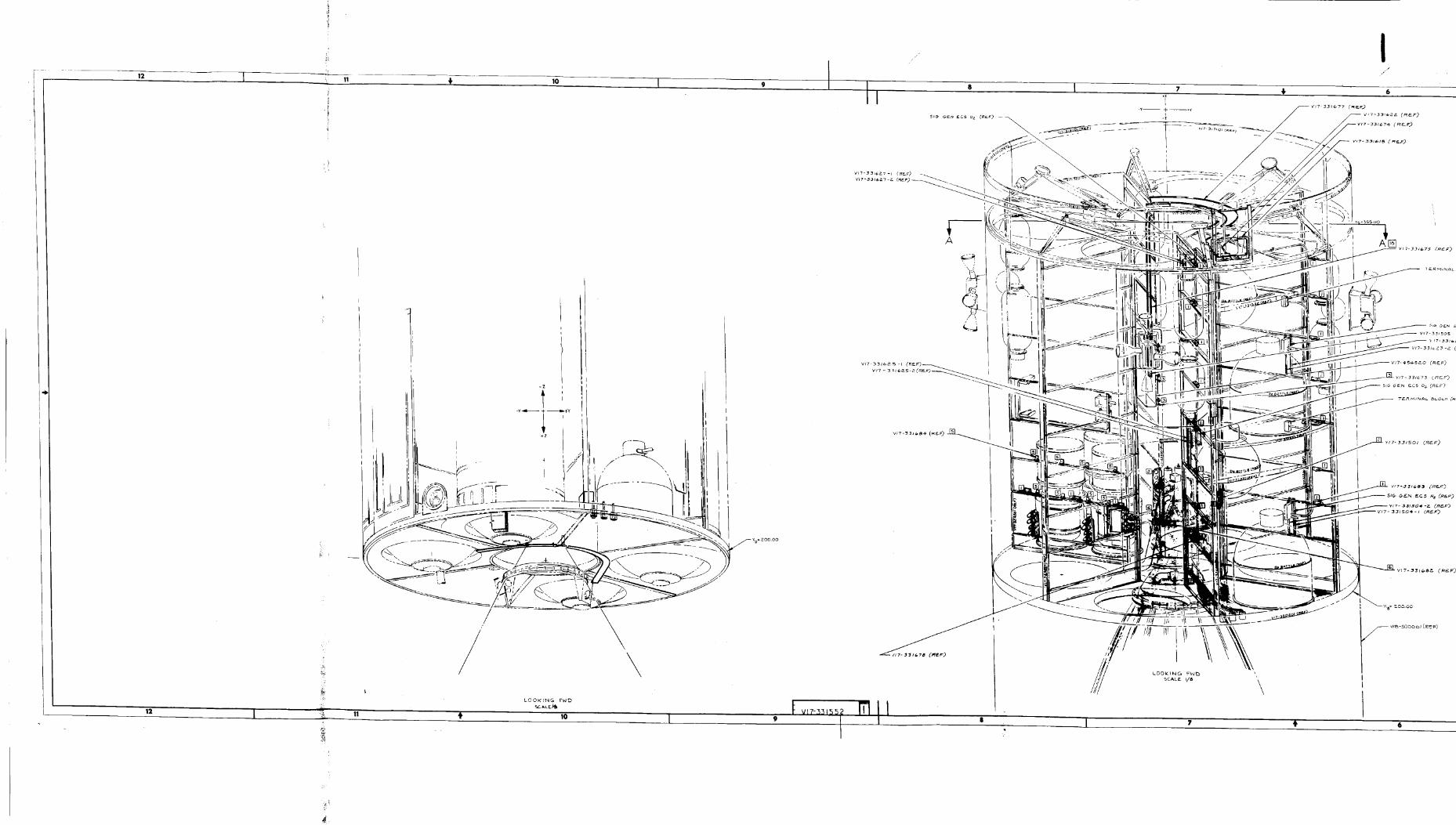
12 L_ 11.._
12 :]::{i
*._: 11
t_.. 10
\\
LO OI'C _N G FWD
"_ _,Lg.l'b
10
/
[ 7
//-
ill! b_;
IrJ!
\
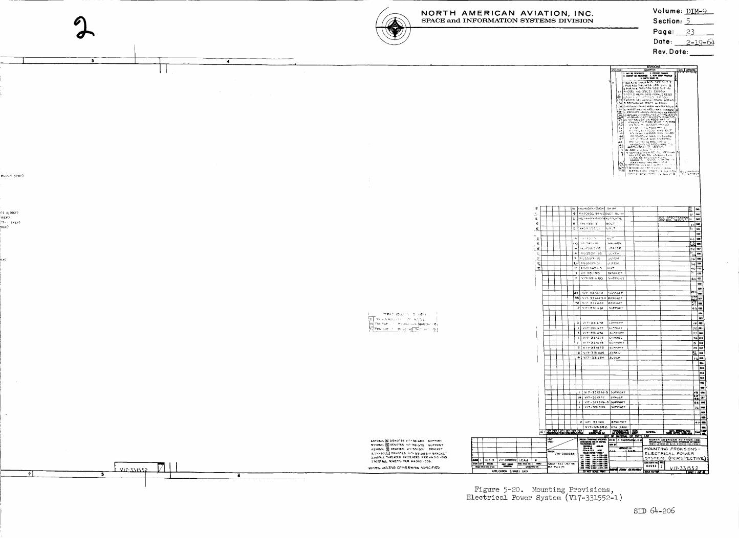
I
,c_ Hz (R_F)
;_EF>
[' _ - I (REF._
Lt
NORTH AMERICAN AVIATION, INC.SPACE and INFORMATION SYSTEMS DIVISION
Vo I u me: D__._.:_
Section: 5
Page: 23
Date: 2-19-64
Rev. Date:
REVISIONS
Figure _<-on=_. Mounting Provisions_
Electrical Power System (V17-33!552-I)
SID 64-206

_t
/
\
XIIEW LOOKING AFT
AT Y,_ - 254-,20
._cJ,LL 11_
-. _:_., _'-_ . .
_0 I _9 _ 18 I..C
P-c ----.
VIEW LO0 KINE, #
__,_-*, {._t_}_ _o_._._
m_*b5_-9 - m Z eEe,9
v_EwF-FI_I
view O -d []
22 I
I
L w_EwBNASlIB_ c _ _ ;'E@_ 6C_,L
L v_EWC-
ViEW D
IB
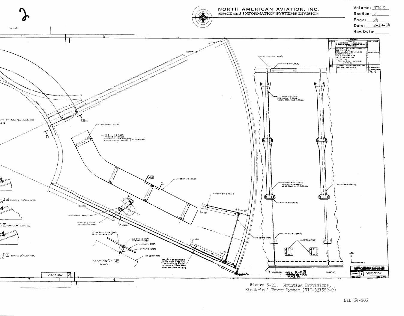
\
\
NORTH AMERICAN AVIATION, INC.SPACE and INFORMATION SYSTEMS DIVISION
Volume: DIM- 9
Section: 5
Page: 24
Date: 2-19-64
Rev. Date:
)
(
"........ Ill Il'z. _'b'b_ b i_ -z5 b_N1 •
i 11...............'% 4
Figure 5-21. Mounting Provisions_
Electrical Power System (V17-331552-2)
sz_ 64-2o6

I
I i
/
/
,I /Iq
FUEL GELLCR_
ill i _ :iti i I I , i
tl. ' ....... ,,
I d I I, | i i
\
S.e_! Yl
; i i .............. i I

/
/
c_L O_Fr_
1
FUEL CrLL_£_
NORTH AMERICAN AVIATION, INC.SPACE and INFORMATION SYSTEMS DIVISION
T • I
Volume: DIM-9
Section: 5
Page: 25
Date: 2-19-64
_ / ! ............ _ ........ "'1| /Bi q"l ,.v,_-33,s,.-,, _.. v,_.,s,5,8 ]d'_._-*l
w_ -- _ v_ (_) _
'_T
DgT/:I,L B []
I TR_CE_IuTY 5Y_SOL_ I
E TR/_CEA_ILITY NOT Rl_0._
T_ T_C[_ILt_ S'( _E_I_L NO[ _O_OI-O_O8NUT
BOLT
mOLT
BOLT
W£8
JhIS TI.
_m
i
Figure 5-22. Installation of Fuel-Cell Mounting_
............. e_ Web _VII-jjI524)
S!D 64-206
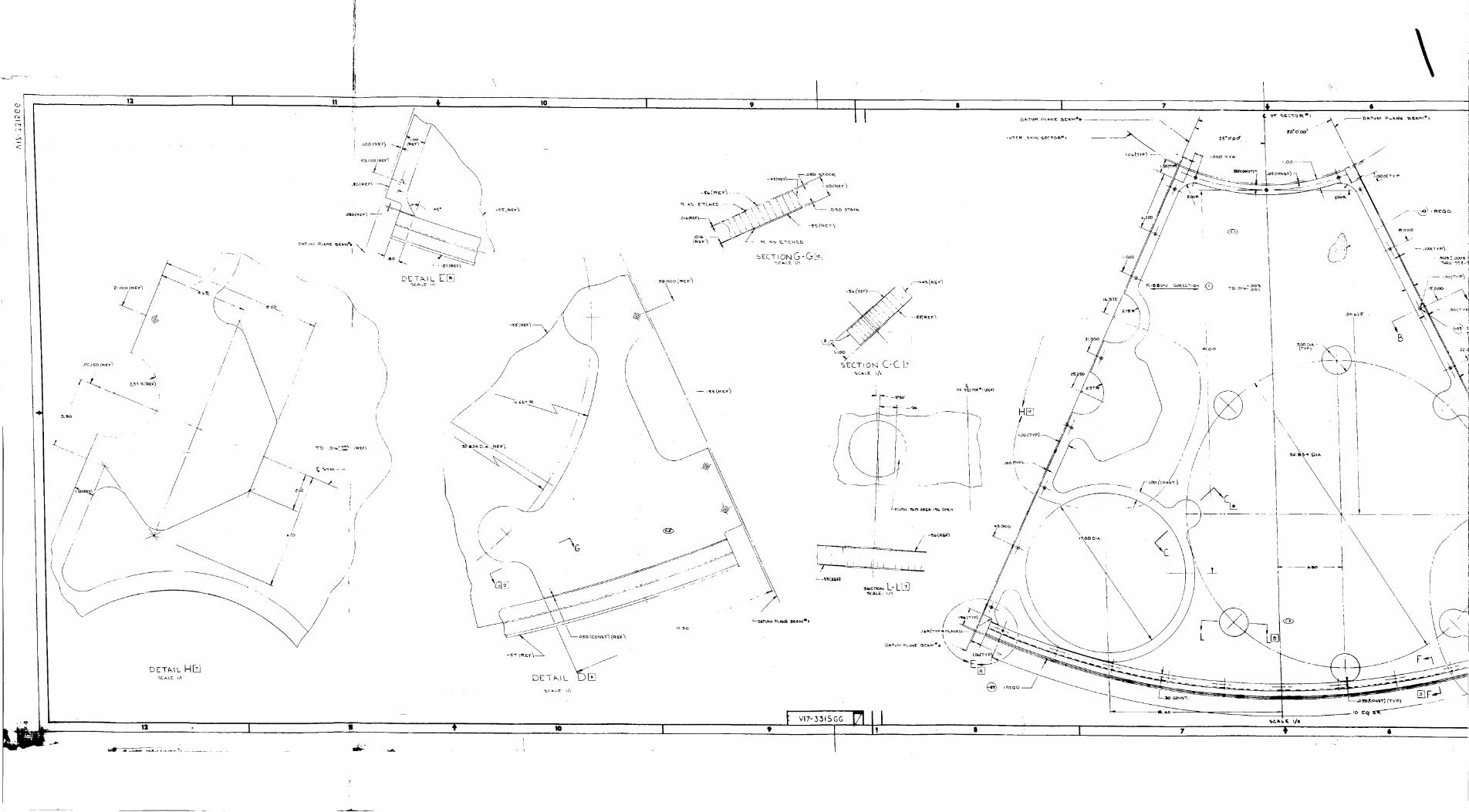
o.Jc_a
c_
.A
,2 I io I 9 I Ii I
\
r
nE-r_L H_
jr
/
/
/
12 I !1
//
/
iH_
/
//
B
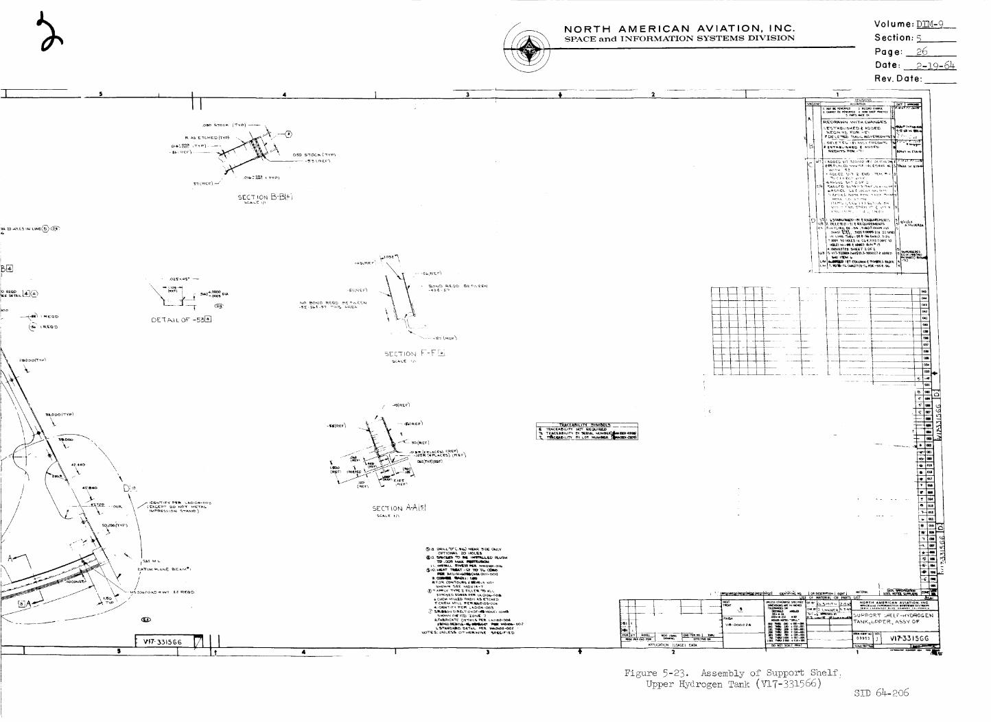
4=
iIB[]F)I
iooI
II
.oso _Toc_ (T,_p) ---- \
DKq N_ L Or -55_
t Vt7- 5315GGI =
_.o_'_
/, '\
/-- j_
scc-__0t_A-A[_I
NORTH AMERICAN AVIATION, INC.SPACE and INFORMATION SYSTEMS DIVISION
Volume: D_-9
Section: 5
Page: 26
Date: 2-i9-64Rev. Date:
9, CmNI _1: 1_
J _T OF MATE_#L OR P/_TS UST _J#_
_._ _*_." .
Figure 5-23. Assembly of Support ShelfUpper Hydrogen Tank (V17-331566)
_To,__D64-206

ll
. °.+,.
_.i I
\
i
_mII
SCALEL,
#
c,._/
L_,c,_u,._, ! ,_
4i, tl
_ML
SEC 77
5C,_L6

.I----.--.---.---.
NORTH AMERICAN AVIATION, INC.SPACE and INFORMATION SYSTEMS DIVISION
Volume: DIM-9 __
Section: 5
Page: 27
Date: 2-19-64
Rev. Date:
Figure 5-24.
Mill _TA
Control Layout - Electrical Power System Hadiator_
Sectors One and Four (V17-933074)
SiD 64-206
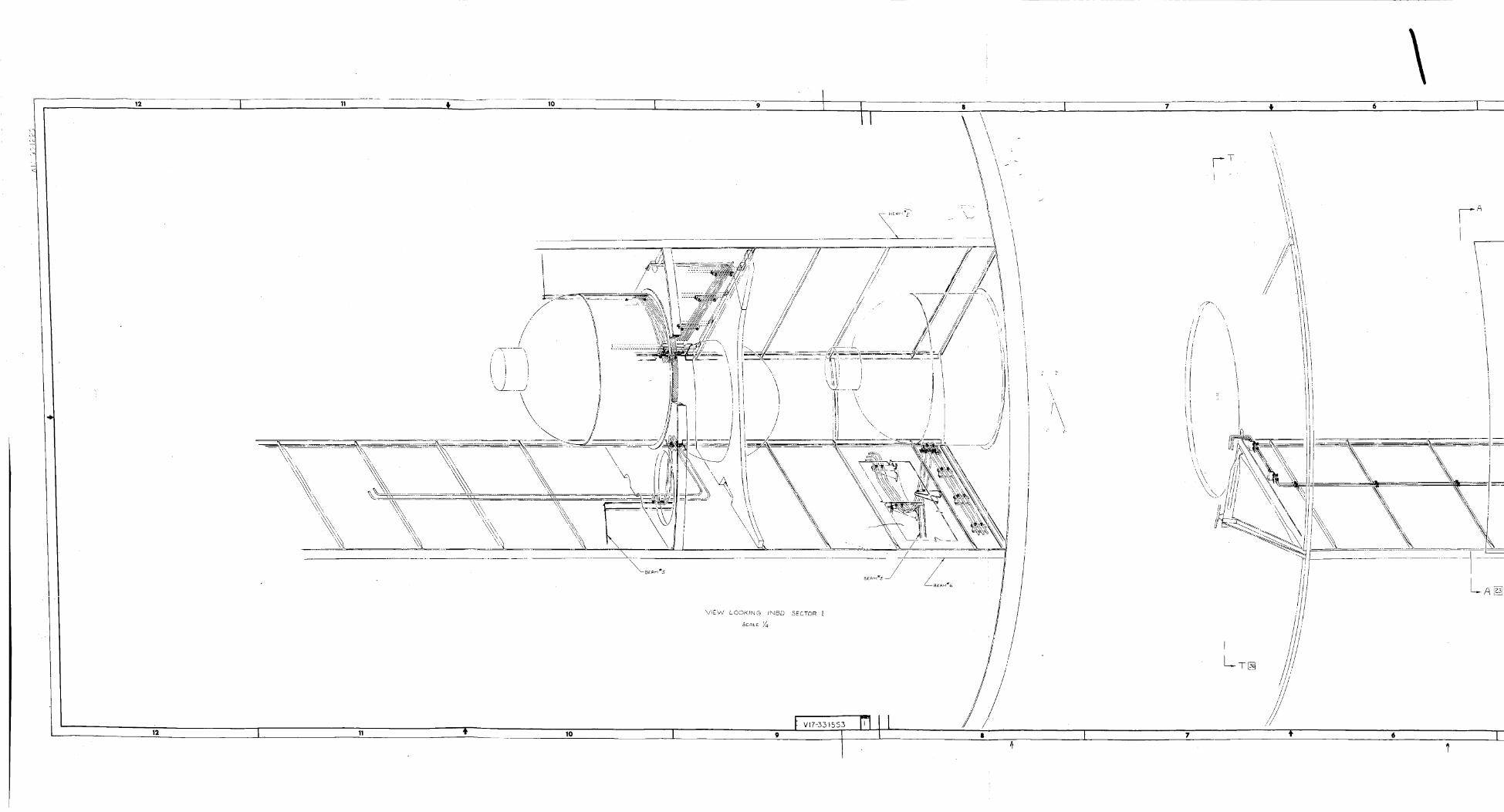
12
12
I11
//
\\
I
/
VIEW LOOKING INBD SECTOR
SCALE r/4
lO
I
I Z
//
\
I
/
///
'\\
//
\,
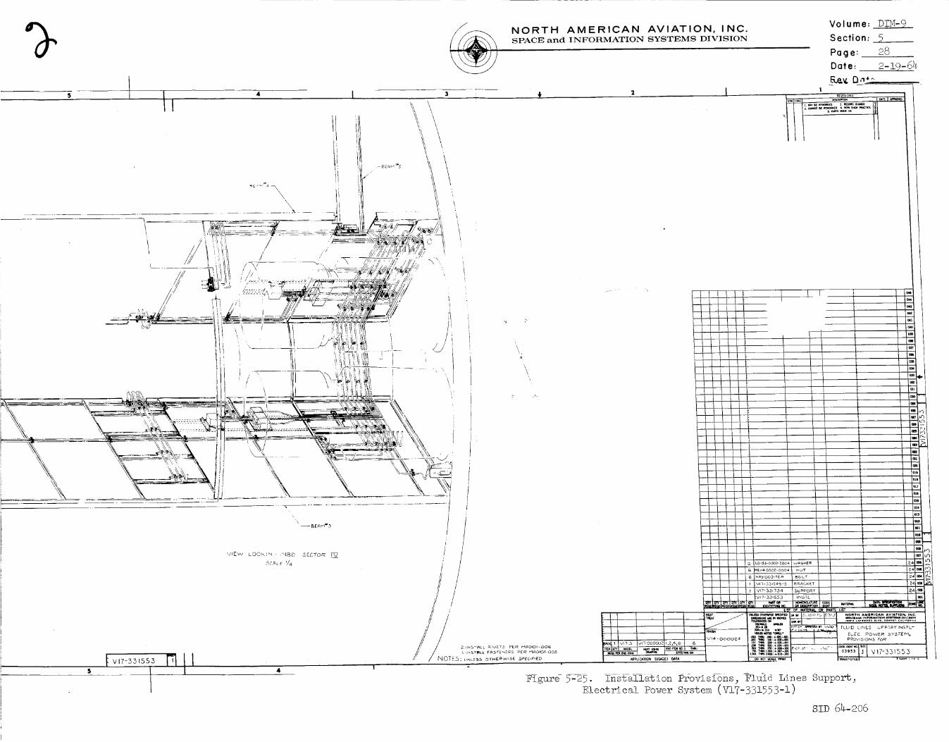
//
/ / '/
/ /
\
\'I
1
NORTH AMERICAN AVIATION, INC.SPACE and INFORMATION SYSTEMS DIVISION
Volume:
Section:
Page:
Date:
Ke,,v. Da,_-.I
IIv........x
DTM-9
528
2-19-6_
\
i
i
Installation Provisions_ Fluid Lines Support
Svstem (V!7-331553-!)
SID 64-206
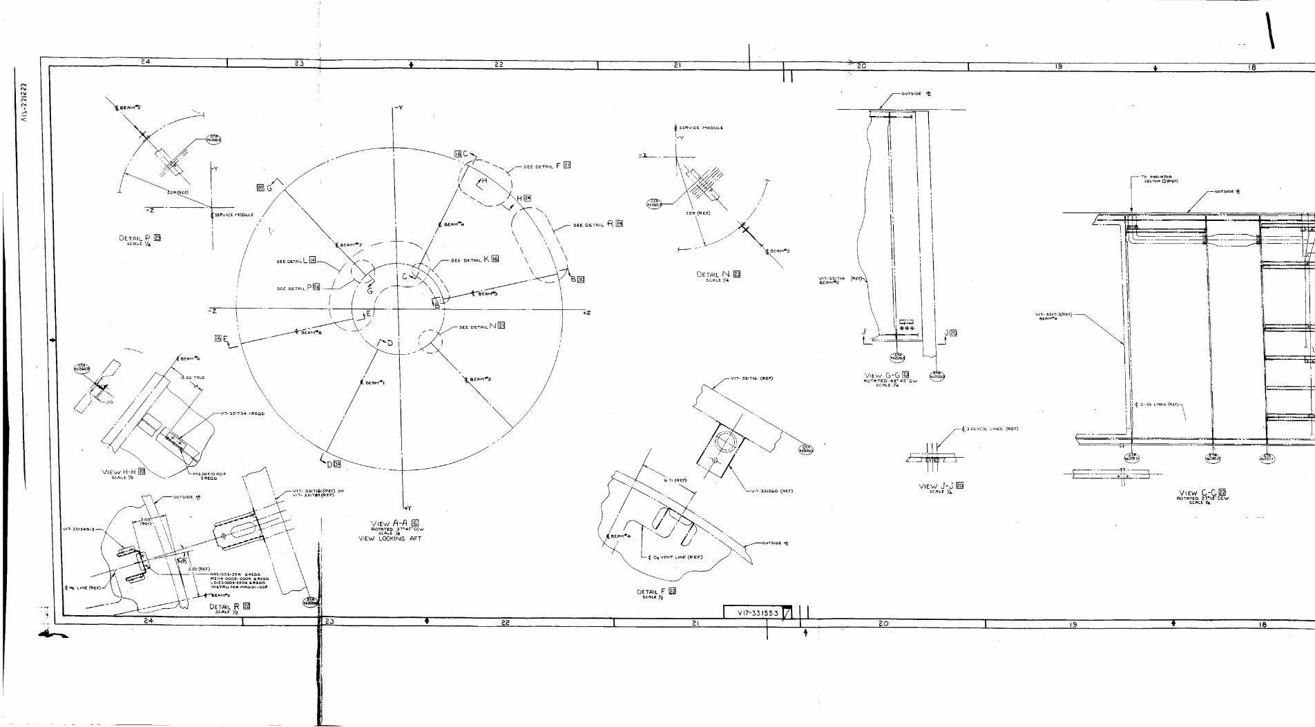
L_'ES (RE_)
w_w C-C__OT_T£D _IS'CCW
5CMLE_4
18
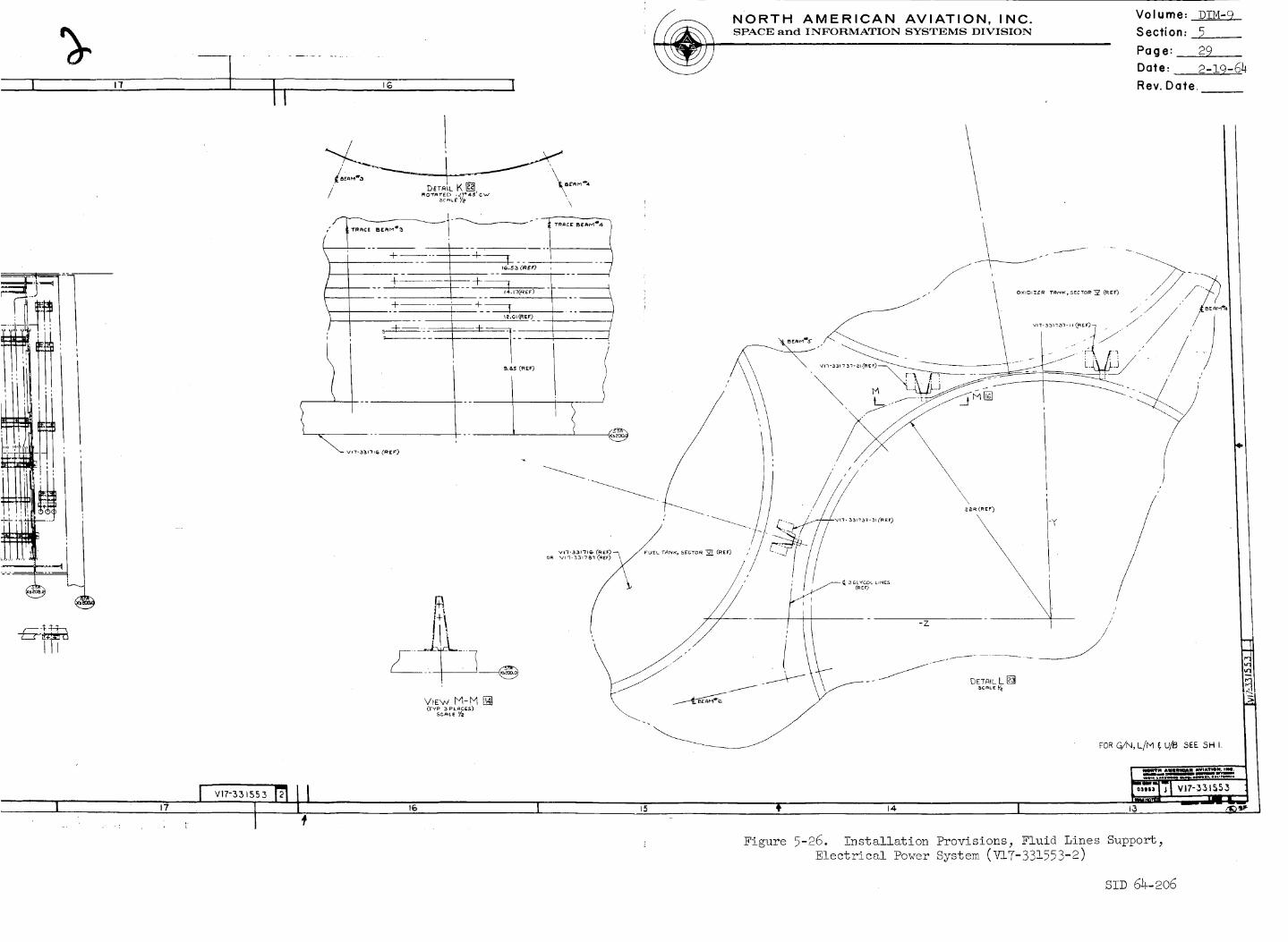
, I 17
NORTH AMERICAN AVIATION, INC.SPACE and INFORMATION SYSTEMS DIVISION
Volume: DIM-9
Section: 5
Page: 29
Date: 2-19-64
Rev. Date.
i 17
VI7-551553
i nll,V17-331553
Figure 5-26. Installation Provisions; Fluid Lines Support_
Electrical Power _'o+=_ (_n?-_-2]
SID 64-206
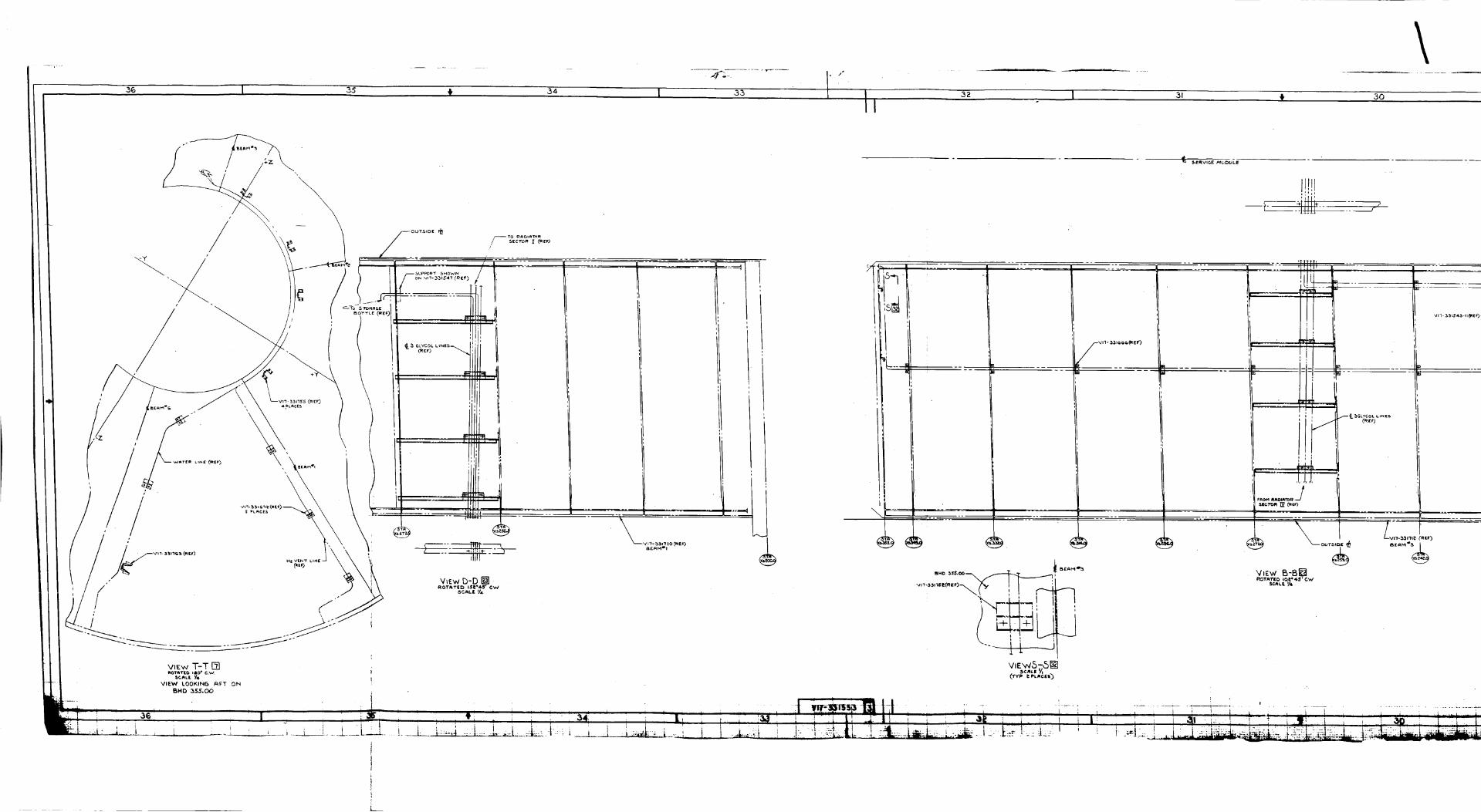
38 35 34
/
\
II
36
}
h.. -- __
35
_Y
5--]-
S
_Y
32 31 t 30
I_ I_£RVIGE /_/GDULE
frl?
I
I.° ""
vn- 331r_ c,r. (_ E r)
.... 3311SE{R|F)\(_
_y
ROT_T(O IOEe4,_'GM#
................. k ...... _

2S 28 I
NORTH AMERICAN AVIATION, INC.SPACE and INFORMATION SYSTEMS DIVISION
Volume:_
Section: 5
Page: 30
Date: 2-19-64
ffev. Date:
_- SERVICE _10 D UL f.
q
i
L-
I
View E-E []SC_LeV4
FOR G/N, Llhl_U/8 SEE ,SHt
I"
Figure 5-27. Installation Provisions, Fluid Lines Support,
Electrical Power System (V!7-33!553-3)
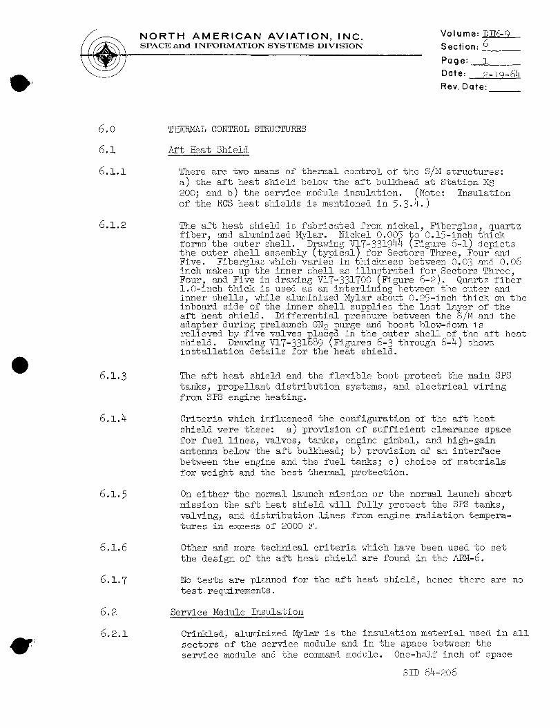
NORTH AMERICAN AVIATION, INC.SPACE and INFORMATION SYSTEMS DIVISION
Volume: DIM-9 _
Section: 6
Page: i
Date: 2-19-64
Rev. Date:
6.0
6.1
6.i.i
6.1.2
6.1.3
6.1.4
6.1.5
6.1.6
6.1.7
THERMAL CONTROL STRUCTURES
Aft Heat Shield
There are two means of thermal control of the S/H structures:
a) the aft heat shield below the aft bulkhead at Station KS
200; and b) the service module insulation. (Note: Insulation
of the RCS heat shields is mentioned in 5.3.4.)
The aft heat shield is fabricated from nickel_ Fiberglas_ quartzfiber_ and aluminized Hylar. Nickel 0.005 to O.!5-inch thickforms the outer shell. Drawing V$,7-331944 (Figure 6-1) depictsthe outer shell assembly [typical) for Sectors Three, Four andFive. Fiberglas which varies in thickness between 0.03 and 0.06
inch makes up the inner shell as illustrated for Sectors Three,Four, and Five in drawing V17-331700 (Figure 6-2). Quartz fiberl.O-inch thick is used as an interlining between the outer andinner shells, while aluminized Mylar about 0.25-inch thick on theinboard side of the inner shell supplies the last layer of theaft heat shield. Differential pressure between the S/M and the
adapter during prelaunch GN2 purge and boost blow-down isrelieved by five valves _laced in the outer shell of the aft heatshield. Drawing V17-331889 (Figures 6-3 through 6-4) showsinstallation details for the heat shield.
The aft heat shield and the flexible boot protect the main SPS
tanks_ propellant distribution systems, and electrical wiring
from SPS engine heating.
Criteria which influenced the configuration of the aft heat
shield were these: a) provision of sufficient clearance space
for fuel lines, valves_ tanks, engine gimbal, and high-gain
antenna below the aft bulkhead; b) provision of an interface
between the engine and the fuel tanks; c) choice of materials
for weight and the best thermal protection.
On either the normal launch mission or the normal launch abort
mission the aft heat shield will fully protect the SPS tanks,
valving, and distribution lines from engine radiation tempera-tures in excess of 2000 F.
Other and more technical criteria which have been used to set
the design of the aft heat shield are found in the ARM-6.
No tests are planned for the aft heat shield, hence there are no
test requirements.
Service Hodule Insulation
Crinkled, aluminized Hylar is the insulation material used in allsectors of the service module and in the space between the
service module and the command module. One-half inch of space
SID 64-206

T_
¢b
'1
12
\
/"
12
v_Ew A -A I_1
1 II 4, ...... Io I
\
SEC-_ON B-B_
t
,7; / ;1
/

4 I
NORTH AMERICAN AVIATION, INC.SPACE and INFORMATION SYSTEMS DIVISION
Volume: D!M-9
Section: 6
Page: 2
Date: 2-19-64
Rev. Date:
/
• 2 / d
/,
P!
%
1
-__:, ', E El4.,• -L',4
-\
--%
b4 I
Figure 6-!. Outer Shell Assembly, A£t Heat Shield,
Sectors Three, Four, and Five (V17-331944)
SiD 64-206
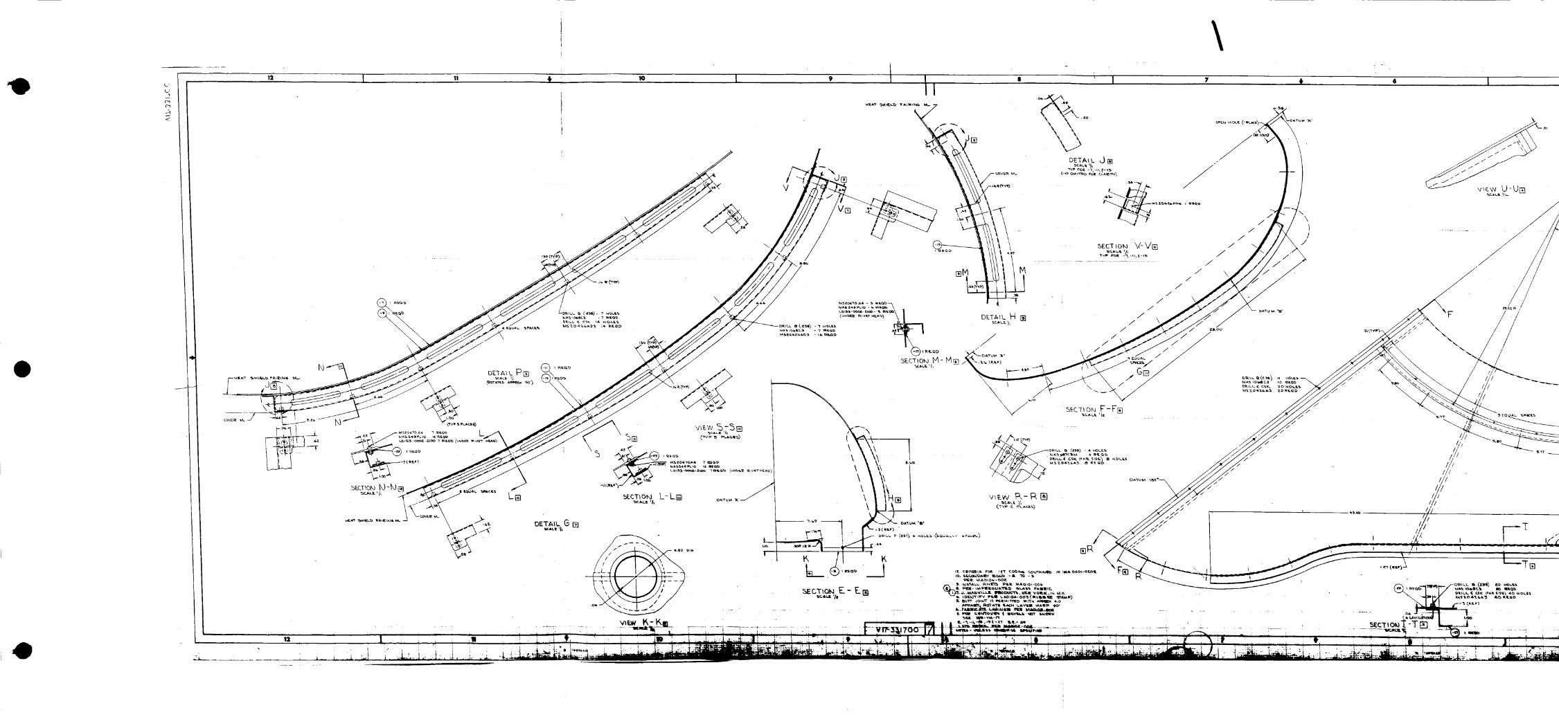
L
01
<
12 I! 10
\I 7 + 6 I
V
M
/
//
//
//
/
/
//
//
//
/\
////
////
//
/
//
/// F T

[]
\
\\
\
SK._LI. 'll.
\
\
\
NORTH AMERICAN AVIATION, INC.SPACE and INFORMATION SYSTEMS DIVISION
\
\\
\\
\\
\\
\
\
Volume: DIM-9
Section: 6
Page: 3
Date: 2-19-64Rev. Date:
Figure 6-2.Sectors
inmer Shell Assembly, Aft Heat Shield,
Three, Four, and Five (V!7-33!700)
SID 64-206
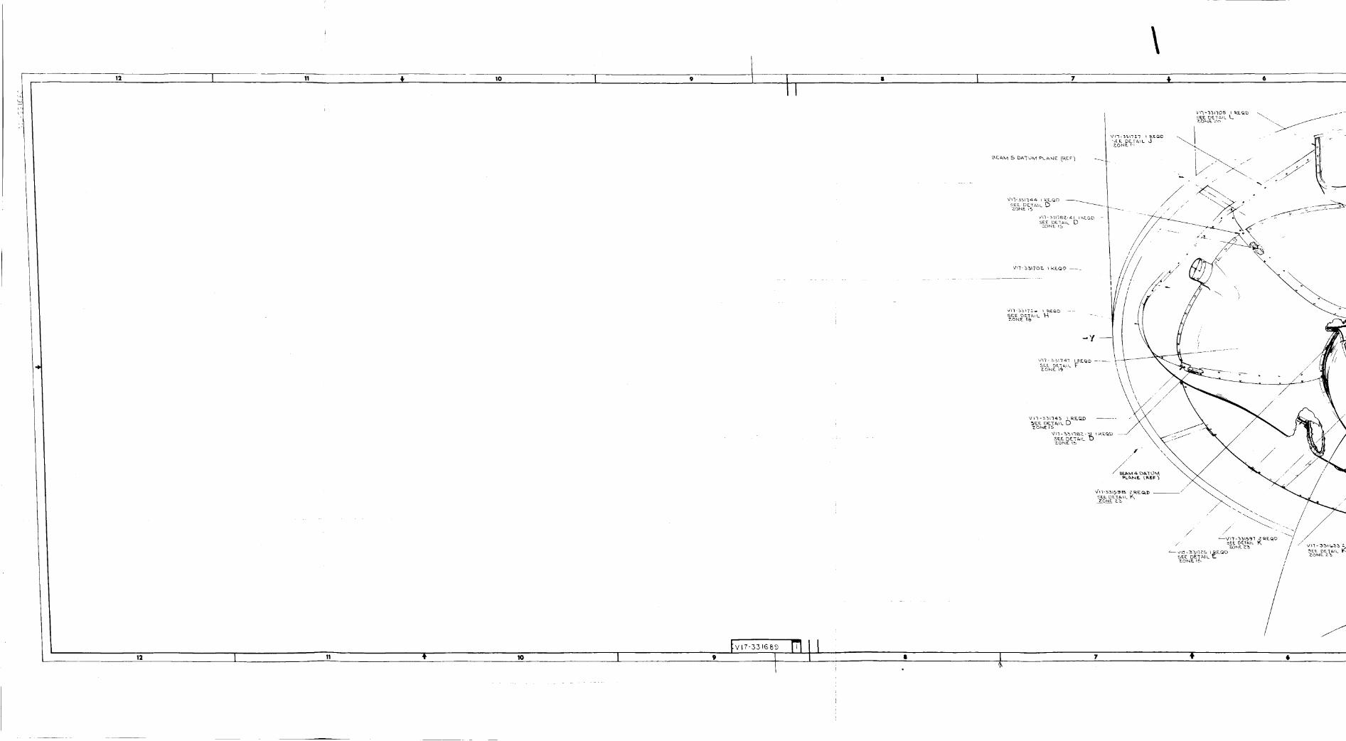
rI
12 11
12 !0
tv,7-++,++__11° t I
\6
|
\\
/,
7 t •
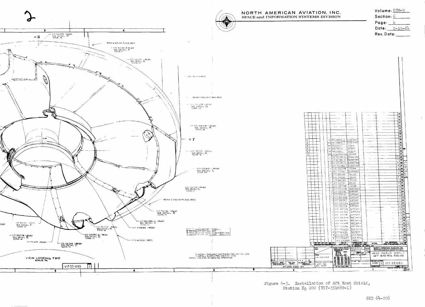
%
/'
\\
/ \
I
/r
//,/
/
I
NORTH AMERICAN AVIATION, INC.SPACE; and TNFOI:I1M.A.TIOiN SYSTEMS DIVISION
Volume: DIM-9
Section: 6
Page: 4
Date. 2-19-64
Rev. Date:
7_o_E LZ
SE£ DET_,_L H
SEE. DF._'[_I L _,
_EA, M Z Dt_TUK,1 P_-_kixlE ('R£JF]
7 l_?_-.l! I RfQDSE.E D_T_.IL U
Z-_4%T&L%- T_RtSDEO e_s_tRs PER _n_ol-oo5
NOT_ ¸ L)_-_% O_LR_I_ 5PE_ED
VI?-331G89
Eigure 6-3. Installation of Aft Heat Shieid_
Station XS 200 (V17-331689-I)
S!D 64-206

Z4
t
__-_ _. _wX
\
\
\\
i
L
I.¢.. lll.l. Ijli
(,<.,_,,,,,,.,.,,<><=,-,-,o,,,<,,-,
. _ - --.
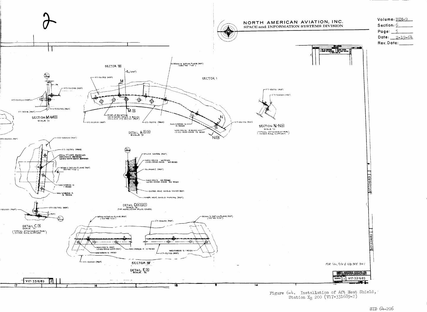
NORTH AMERICAN AVIATION, INC.SPACE and INFORMATION SYSTEMS DIVISION
/SE.CTOK ]Z_ / (zbz-4_, nzs")
-?-s t_'_o') ! !
/
M
s
Uw ,.1_5,,q3, ,,__,)
N-MI_ .... '-" ........ _
,..W( _ Zo.o.,.,..._....
I
DETAIL DI_N_
DETaiL C []S e.. _, L._.. 'I_ //'_ I'_L _ \ \ \ \
,--vn-_zozo,(,_,? SECTOI_ _ -
DE'[/_,,L E lEi
I.,7-_,_'mII - -...;-_ • " -,T ,I .I S ,_ ! " .... '_ ' • '"
I
Figure 6-4. Installation of Aft Heat Shield_
Station X S 200 (V17-331689-2)
Volume: DIM-9
Section: 6
Page:
Date: 2-19-64
Rev. Date:
smD 54-_o6
NORTH AMERICAN AVIATION, INC.SPACE and INFORMATION SYSTEMS DIVISION
Volume: DIM-9
Section: 6
Page:
Date: 2-iO-64
Rev. Date:
6.2.2
6.2.3
6.2.4
6.2.5
has been allotted for insulation, even though the total thick-
ness of the Mylar layers uncompressed will be only 0.25 inch.
Installation accessories are hollow aluminum rods, nylon buttons,
cords, and thread; spring clamps; and reflecting pressure-
sensitive tape. Drawing V17-331562 (Figures 6-5 through 6-6)
shows the perspective of the insulation-installation provisions.
The function of this insulation system is to supplement the aft
heat shield in the dissipation of heat from any source and to
keep the SPS tanks, propellants, and other equipment at an even,
nondestructive, proper, operative temperature. The insulation
system also prevents loss of heat in the cold environment of
space.
Criteria which governed the choice of aluminized Mylar (NRC-2)
as insulation material are these: a) it is the best reported
insulation value per pound; b) it has the ability to withstand
high compression of large g loads while maintaining initial
insulation effectiveness; c) its low bulk density is needed to
achieve thermal equilibrium with a minimum loss of cryogenic
fluids; d) by its use a high vacuum can be obtained; e) it is
easy to apply to complex shapes; f) a minimum effect is obtained
from thermal short circuiting.
During the normal launch mission or the normal launch abort
mission the thermal insulation system will protect the SPS tanks
and internal equipment of the S/M from environmental temperature
extremes generated externally. The insulation will maintain
the temperature range of 80 through 40 F for the propellant dur-
ing the mission.
Test requirements for the thermal insulation system are stated
in SID 62-109-2, "General Test Plan, Research and Development
for Project Apollo Spacecraft, Individual System Test." ATR
306, "Thermodynamic Analysis of the Typically Insulated S/M
Propellant Sextant," has not been completed since the test has
not been run. However, design work has begun on the thermal
simulator - test specimen. Drawing DTT-6600 (Figure 6-7) gives
details ol _ae SPS tank-insulation assembly. If additional
information is desired, contact can be made with Department696-210.
SID 64-206
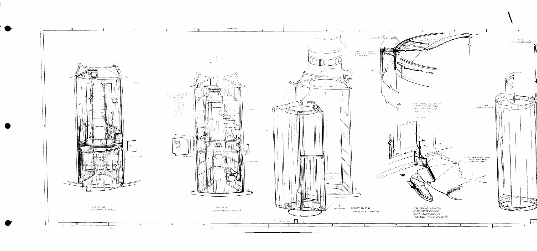
12 1 ,o _ - 9
\
k _ d ,rOl__ 2][_
m,v mEr_,/._ SEE ZO,VE _/ I
LEC TOP9 I
(FD_LTErm/Z5 SEW ?ON_ /5 >
_ 12 J 10
/
/
II
t
\
. I
-<I _ 7 (_EF)
V/E_V 5HOWINO IHSUL,gTION
JTT_CNED TO AFT TJNK-
5KiI{T ; /NA/6/_ ,qND OUTE?
<;?E_-j' \
I
J\
.]= , .
F<<
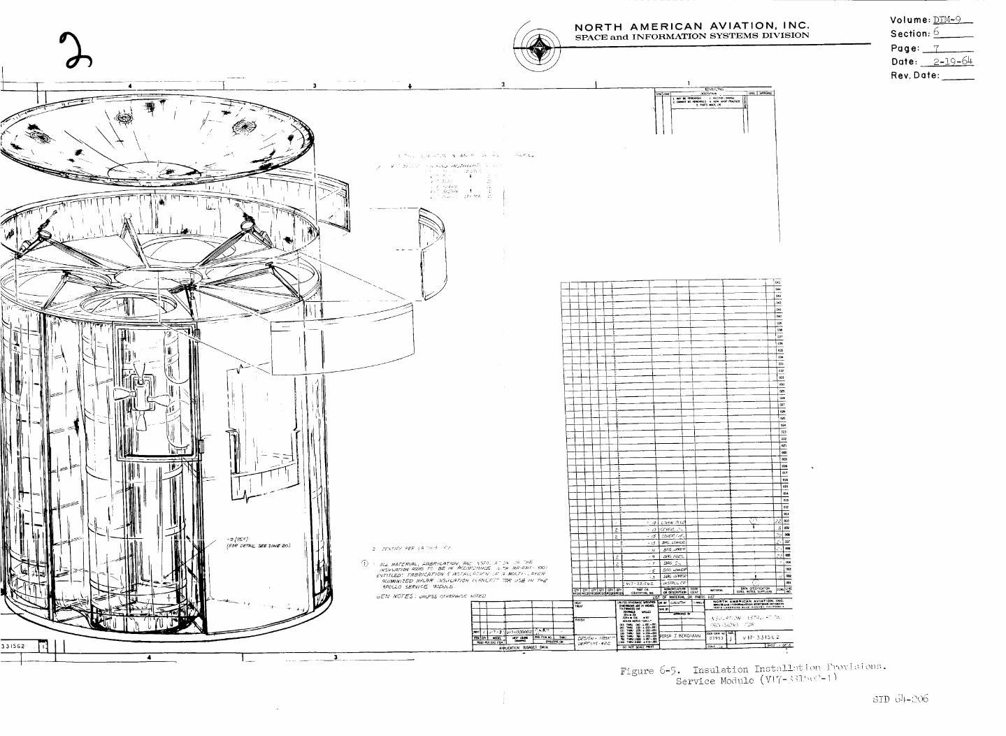
\
%
I ....
NORTH AMERICAN AVIATION, INC.SPACE and INFORMATION SYSTEMS DIVISION
I 1
IIL
Figure o-5 • _ ...... _" Tl,-l_,t._] 7 "_1= T L'_]'_ ]"t*>V i i OI'_S
Set-v-ice Module (V:I7-_ _] "_"'- I ]
Volume: D!M-9
Section: 6
Page: 7
Date: 2-19-64-
Rev. Date:
s]-D dh--2o6

Ci_3LL_
24 I z3 '_
VIEW
\
22 / 21
?
5_ ,_?o_vA-A
q-K ._t.__-- --I._
_-_24
sPc T/OA/ C-d
I 23 22
f VlT-331562
-t.-- 2i ao I ÷ le t m I
_-z TYP AT _P3'_
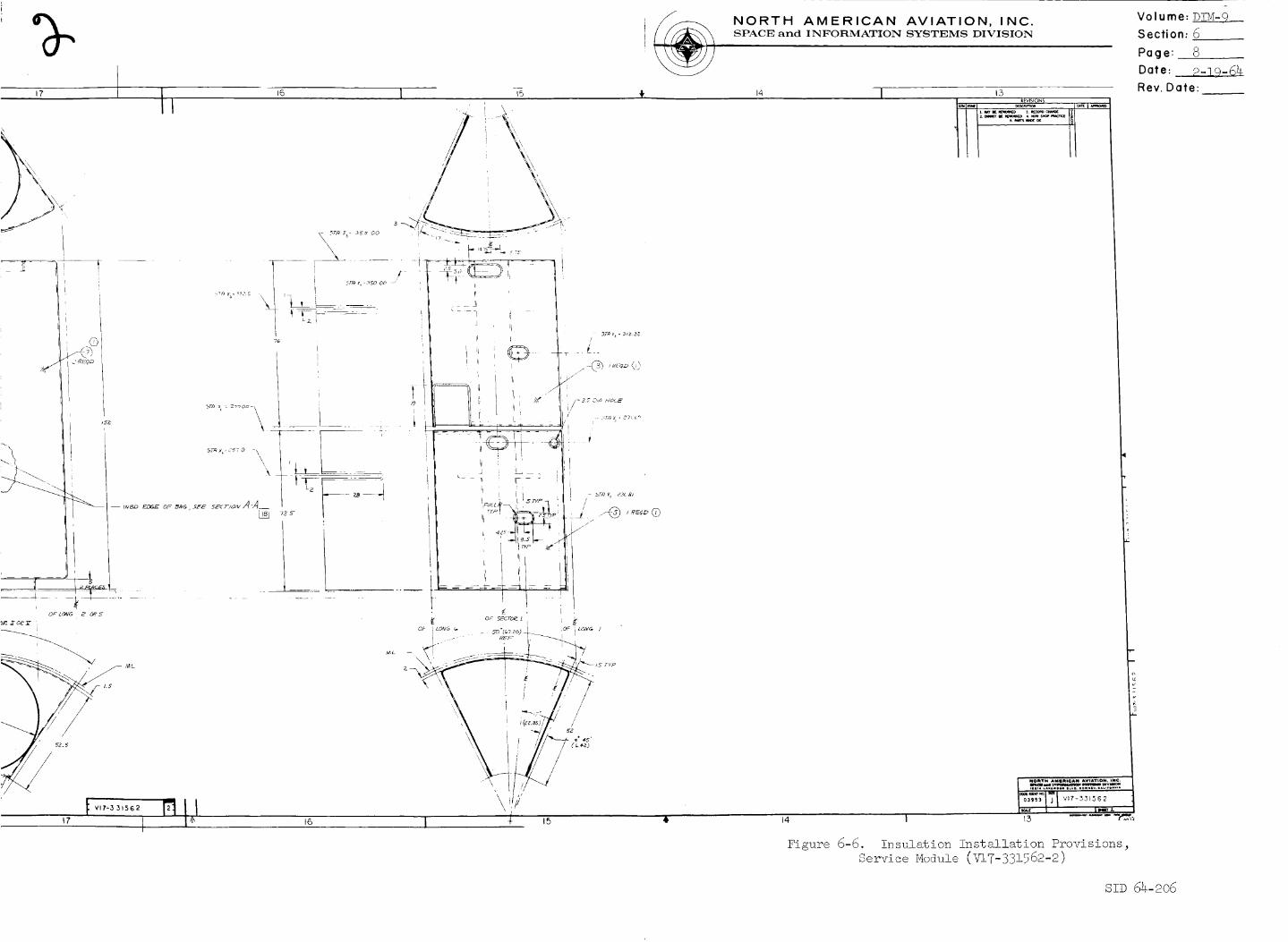
17 11
I
NORTH AMERICAN AVIATION, INC.SPACE and INFORMATION SYSTEMS DIVISION
16 _I, 14 I17
I....ii..................03_S_ J V17-551562
I ,_,,, l I"'_ _
Figure 6-6. Insulation Installation Provisions,Se_v-ice Module (V17-331562-2)
Volume: DIM-9__
Section: 6
Page: 8
Date: P-39-6_
Rev. Date:
SID 64-206

\
fx= 3ss
i
[ Ii I 7
8 I 7 t

% NORTH AMERICAN AVIATION, INC.SPACE and INFORMATION SYSTEMS DIVISION
!
Volume: DTM-9
Section: 6
Page: 9
Date: 2-19-64.
Rev. Date:
, _ DTTGGo_2K_k__
Figure 6-7. Complete Assembly o£ Thermal Simulator for Specimen Test(DTT-6600)
SID 64-206
NORTH AMERICAN AVIATION, INC.SPACE and INFORMATION SYSTEMS DIVISION
Volume: DIM- 9__
Section: 7
Page: !
Date: 2-19-64
Rev. Date:
7.0
7.1
7.1.1
7.1.2
7.1.3
7.1.4
7.2.2
7.2.3
SIGNIFICANT INTERFACES
General
By the term "interface" is meant the common boundary between
two or more systems or subsystems. At their points of contact_
matching or accommodation must be properly achieved to assure
compatibility and successful functioning.
Significant interfaces are divided into two categories: a)
those which are external, affecting structures; b) those which
are internal, affecting such things as mechanics, hydrau!ics_
pyrotechnics, and things electrical.
Some of the external interfaces are in the study stage. As the
studies crystallize into designs, the resultant drawings willbe added to later editions of this manual.
All of the systems-mounting provisions are really interfaces.
However_ these provisions are separately treated under heading5.0.
External Interfaces
The fairing_ an important part of the S/C is one of the chief
aerodynamic interfaces between the S/M and the C/M. It is made
of six equally sized panels fabricated from bonded aluminum-
honeycomb sandwich one-inch thick. Installation drawing
V!7-3!0001 (Figures 7-1 through 7-2) and panel assembly drawing
V17-3!!001 (Figure 7-3) depict the fairing interface. The
function of the fairing is twofold: a) to shield from atmos-
pheric pressure certain equipment essential to the smooth
functioning of the S/M and C/M; b) to prevent rapid evacuation
of air from the S/M interior.
The C/M to S/Mumbi!ical with its own fairing is the second
vital interface. This fairing is located in Sector One on the
outer shell of the S/M - C/M f_i_g. D_T_ V17-_q1771
(Figure 7-4) shows configuration details of the fairing. Drawing
V17-331913 (Figure 7-5) depicts these details for the fly away
umbilical. One criterion by which an external structure was
added to the otherwise smooth surface of the S/M was the impera-
tive necessity of finding a route for the umbilical - hard lines
and electrical wiring - such that it would not penetrate the
ablative material of the C/M.
A third significant interface exists between the S/M and the S-I
adapter. The chief feature is a strap-tension tie which also
carries the shaped charges used to separate the S-! adapter
panels from the S/C. See drawing T18-300005 (Figure _ £_I-u} •
S!D 64-206
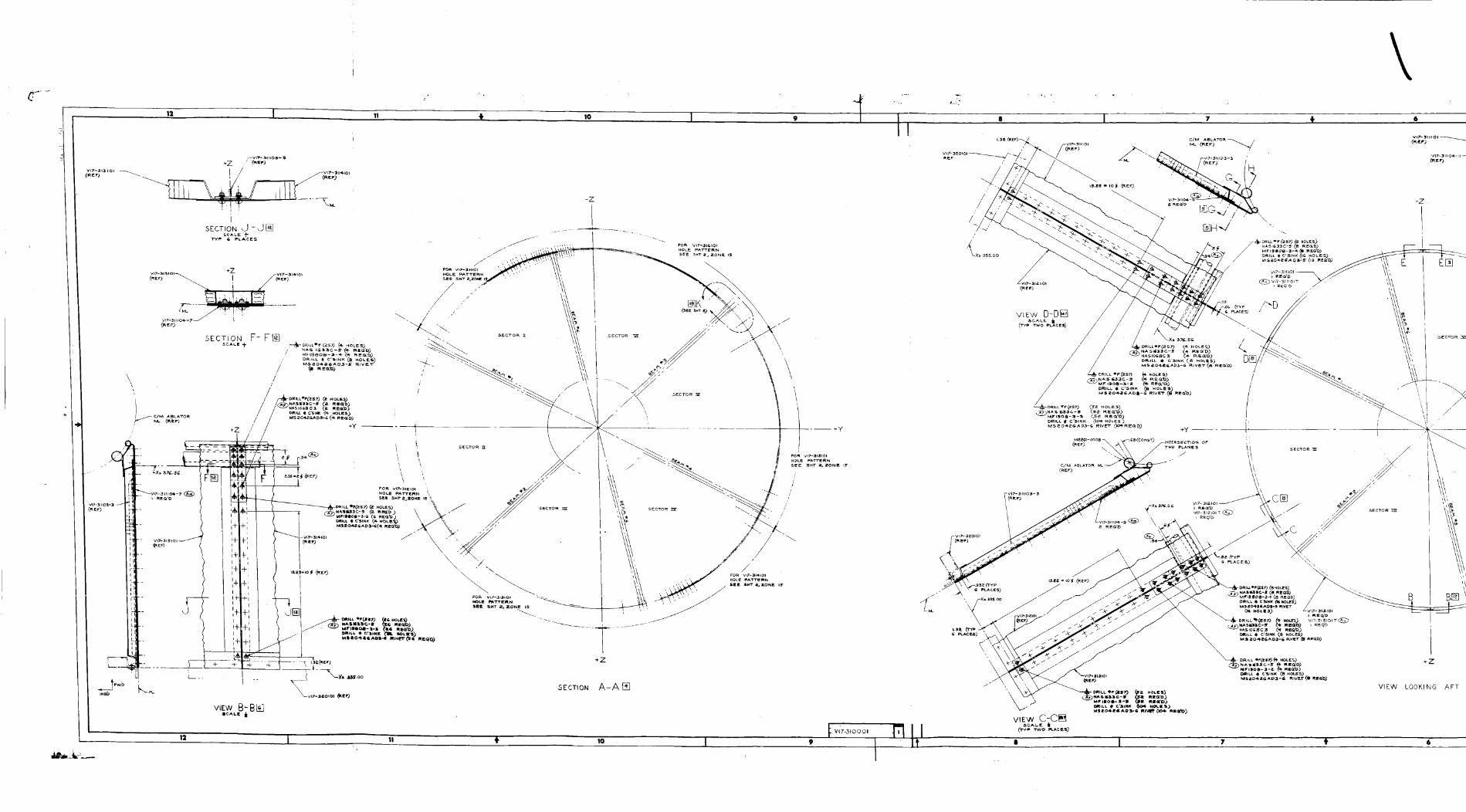
. --
VIEW B-B_
÷z
SECTION A-A []
12t lo I
_ V1'7-310 OOl
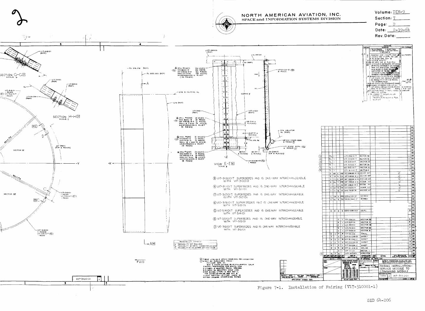
%
I S
+X
/ NORTH AMERICAN AVIATION, INC.SPACE and ]ZNFORMATION S¥STI_,MS DIVISIOIN
Volume: DIM-9
Section: 7
Page: 2
Date: 2-19-64
Rev. Date:
-Xs 355,000 (_E=3
_A
14 .......... Y
®
PLA c Es)
L..A®
FWD
!
Figure 7-1. Installation of Fairing (VI7-3IO00I-I)
SID 64-206

a4 ] 2_--'-----r------ 22 21
J__ Vl?-310 0 0 1 f__
i
VlT--_OIII
(REF)
WEW I_E]SCALE +

._o
NORTH AMERICAN AVIATION, INC.SPACE and INFORMATION SYSTEMS DIVISION
-Z
_ FAIRING ATTACM
i
-t-
-I ; _ RACES)I
.,-:7 f vI
!
-- - / + ........ ...... ÷/_-Lt (2÷.oL_)_.w_,,,o,.v,,._,_. / _,_L _ ('_ .o_Es._,. v,_-_.,o,.v,_-_-,ou VI7-31_1OI FLAT PATTERN (_E S_CT_ONA-A
(_ NAtIoi_'l- _ R[Q'°) NAS 1_34C-7 (*e _E_'O)
M_20"_AO_-I('_41 RE_O) MS_Q4_GAD3-7 (Si _E_'o)FAIRING A'rl_fJt I DRILL _ C'$1NK _1 HOLE_) D_I, ILL _il C'StNK _l_ HOLES)
I"+.... +• _ I e_a_4,-eeN_ -4,- 4- ÷ ÷ 4- 4- + + ÷ + 4- 4- + + 4- 4- 4- 4- ÷ + 4- + + ÷ ÷ 4- + 4- ÷ ÷ ÷ ÷ +
L-4-" ; 4--
FAIRING A_AC_
_t,-_C-I._ .......
V17-315101 FLAT PATTERN (_EE SEC'r,ON A-A
/
+ Z _- .... _e, ego
#, FAIRING A_TAC_ I_I_A_I e_ _ VlZ-iZOlO7 SPUCE
(_)
VIT-31'HOI FLAT PATTERN (GEE SECTION A°AGCAL_ _r _HI"_Z, ZONE IO)
t ! FAIRING ATTACH
Volume: DIM-9
Section: 7
Page: 3
Date: 2-19-64
Rev. Date:
3,ADDED .1_ 01M ('i PLACES)i ,:'_mi (__,L_c_s.).I I I
w,_$ 4.oo-_,(= pL^C_S). / /D.W/N._#S /
I 1/_,-':-':;:
_ FAIRING ATTAC M
i@ + ÷
,_s 4 L_-- *-f
+
+ZI__ FAI_ING AI"TACH
< rA_R_N6 Arv#o_ I_ SEAM el
-z_ PAl!flING A"t"i*h C H
_ + 4-,,s L'_*9
4,- ÷ + + + ÷ 4- 4- 4- 4- + + 4- + 4- ÷ -L 4- + + + + + -F ÷ + ÷ 4- + ÷ + ÷ ÷
V17-31_I01 FLAT PATTERN (_z_ S_CT,ON A-ASCALE _r a,_'r ,t!, ZONE. IO)
5a,ioo 1
+ + + + 4- + + + + + + + + + + + + _-_i _
_ fAIRING ATTAC _
VI7-311101 FLAT PATTERN (a_E ae¢'r,o. A-ASCALE _ IHT _Z_ ZONE IO_
X_ SSs. oo
I?
17t Vl7-31OOOI L F2It II
16
FOR L/M, GENERAL NOTES,
USAGE, SEE SHT I /
Figure 7-2. Installation of Fairing (V17-310001-2)
sip 64-206

C_
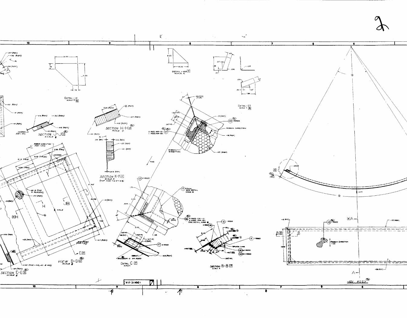
%Io I
/--3c _,--)
\ o
J.,_L
' I _ _ 6 I :
.scA L _ _
'f I 4_
//
//
//
I
\
AqI
-t01 _ S S'Y '''_"
/

\
lev
t w,_3,,°°,Fills I I
I
NORTH AMERICAN AVIATION, INC.SPACE and INFORMATION SYSTEMS DIVISION
Volume: DIM-9
Section: 7
Page: 4
Date: 2-19-64
Rev. Date:
>
•750
M
-- --.t
- - ..-i
-- -----t
- - ---i
- - -..t
.... ----t
-f---_t,,---.°_,8t :_
SEc'noN A-AI_I
I('r*u_
.1_13(r_u#)
t,oo _ (y-)'P
_. 90
LDET,_l_ - _ _U'__
3c,eL_
/£.aa -U-RU_)
(r*u_)
1
I
-Ila.tz
D E T/t l L -53 _:"[email protected]_ ,_
_)_,AP_Y TYPE Z FIkL_ _0 ALe [XPO_[OIDLES PEru LA0t0$--OOI
i.
4
/I-C
- uoa_" .o_ x 01,4 .SHOWN
I.ilil_l li I llmilm lllimlllil iI
Eigure 7-3 Fairing Panel As _=_3_Service Module to Command Module (V17-3!!00!)
SID 64-206

12 10 , I
..... I
i
J
I
I"w
I/ \I 11
\ j, ,I \_ / I
T,
li_q
I
II
I J..LI
I
,P
12 4_ I0 ' I

\\\
\\ \
NORTH AMERICAN AVIATION, INC.SPACE and INFORMATION SYSTEMS DIVISION
Volume: DIM-9
Section: 7
Page: 5
Date: 2-19-64
Rev. Date:
Figure 7-_. Fairing Assembly Complete,
Command Module to Ser__ce Module Umbilical (V!7-33!77!)

q
H -
\
\
i . ,/
\
\
_Z
//
p,
\t
\
\/

I
NORTH AMERICAN AVIATION, INC,SPACE and INFORMATION SYSTEMS DIVISION
z 4.
i
VIEW LOOKING AFT.
AT FAIRING INSTL.- S/_ TO C./_l
, !
Volume: DIM-9
Section: 7
Page: 6
Date: 2-!9-64
Rev. Date:
Figure 7-5. Assembly of Support - Command Module to Service Module
and, Fly Away Umbilical (V!7-331913)

_ NORTH AMERICAN AVIATION, INC. Volume:D!M-9SPACE and INFORMATION SYSTEMS DIVISION S ecti on: 7
Page: 7Date: 2-19-64
Rev. Date:
Figure 7-6. Strap-Tension Tie,
Service Module to Adapter (V18-300005)
szD 64-2o6

NORTH AMERICAN AVIATION, INC.SPACE and INFORMATION SYSTEMS DIVISION
Volume:_
Section: 7
Page: 8
Date: 2-19-64
Rev. Date:
7.2.4
7.2.5
7.3
7.3.1
7.3.2
7.4.2
A fourth external interface concerns the S/M and Adapter-to-
Launch Complex or the GSE umbilicals. Drawing V17-933401
(Figure 7-7) presents the control layout for the servicing and
umbilical locations. The latter are blown away hydraulically
from their respective structures at time of blast-off. (S-I
configuration only; S-5 configuration now in design study. )
Design studies are now in progress for the following external
interfaces:
a. S/M to SLA;
b. SLA to Saturn instrument package;
c. S-IV B adapter to L_;
d. S-I Adapter to S-IV B.
Internal Interfaces
One of the two internal interfaces is between the ECS and the
EPS. Drawing V17-331549 (not included) exhibits a bracket
mounting which binds members of each system.
A second internal interface is between the SPS and the EPS.
Drawing V17-331501 (not included.) likewise shows a bracket
mounting for members of each respective system.
Test Requirements
Tests for interfaces have been scheduled chiefly for separation
systems involving the modules. The test schedule given below is
included in this manual for information purposes. 0nly the
first three tests have been completed.
ATR NO. NAME OF TEST
i00 A
i01
i01-i
i01
I01 A
Separation System: C/M from S/M
Separation System: S,/M to S-!VB
Adapter
S/M Adapter Panel Ejection System
Supplement i - Separation System_
S/M to S-IV B Adapter
Separation System: S/M from
Adapter
SiD 64-206

1;
2
ll I . t Io I 9
t
t
t
<F
/7;J_.
z,: #Z'?,_ .......
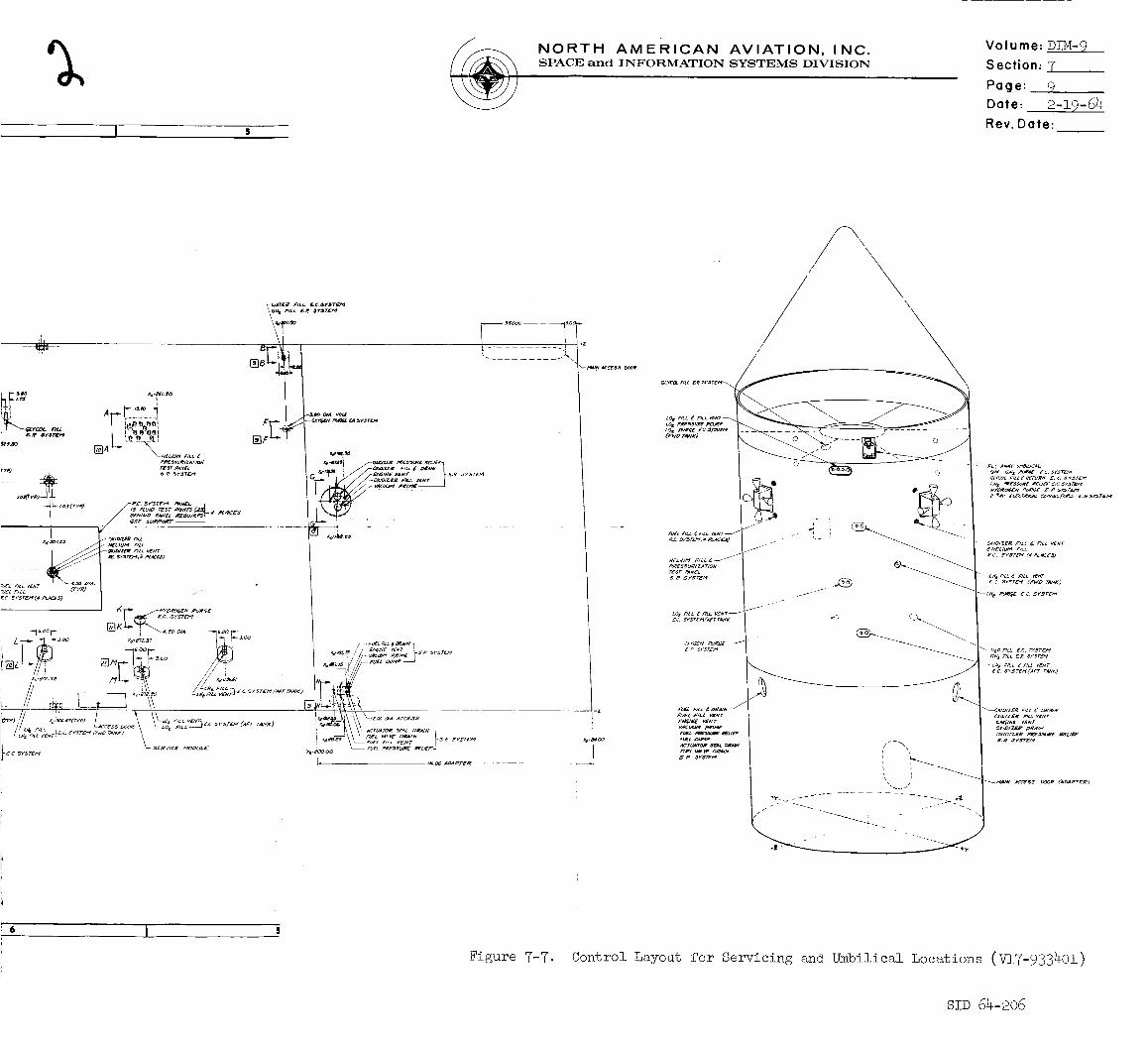
I s
NORTH AMERICAN AVIATION, INC.SPACE and INFORMATION SYSTEMS DIVISION
Volume: DIM-9
Section: 7
Page: 9
Date: 2-19-64
Rev. Date:
Figure 7-7. Control
CL_COt mL _e _rsru_.(
LO I ,qLI. _ FILL VENT_LOI pR_S_U_ R_UEF
FUEL #II.L _ FILL V_NT j
H[Z_U,_I FiLL _ --/
,oRESSUR/ZA7"/O_"rxsr _#_'cs _? srsrEm
co e F_L_ _ F/u_ V_#T_
_ P sr_TE_
,qJ£L F/Lt V_-
E,V_a/g v£_/r
Fus_ z_,_pAcrCllTOlt _L aeAw
, \
it
r-- ,
.I .J i- L-- "
I
CZ_COL f/z_ +_ e_rultW £. c. xvsr_
or/o/zE_ Fat _ _LL V_T
_ C, _YsrDv (_ Pc_cE_)
_--L_ _ EC. 5r._rEM
cN t _ILL _ _r_TE_
-C_ riLL ¢ flL_ VENT
_C _Y_TEM('A_T _KJ
OX/OIZ_e p_ES.SU_e P._C#Br
_.R SVSTE/_
I 'I
\ /' /,_allN ACCE$5 _OOe (_I_APTC_)
Layout for Servicing and Umbilical Locations (V!7-933401)
SlD 64-206

NORTH AMERICAN AVIATION, INC.SPACE and INFOR_IATION SYSTEMS DIVISION
Volume: D!M-9 ,
Section: 8
Page: 1
Date: ____4Rev. Date:
8.4
8.5
8.6
REFERENCES*
IOL AE-I-62-313, dated 5 December 1962, from C.H. Feltz, Department 695-i00_
to Apollo Engineering Management_ on subject of Apollo Engineering Manuals.
NASA Exhibit "B" Technical Specification_ Fart I. 3 January 1963.
Composite Construction £or Flight Vehicles_ Part III_ Design Procedure_
MiL Handbook 23.
Apollo Test Requirements Status and Coordination List. NAA S&ID_ 17 July
1963.
Command Module and Launch Escape System Structures. DIM-8_ Apollo Systems
Engineering Manual. NAA S&ID, 7 August 1963.
General Test P!an_ Research and Development for Project Apollo Spacecraft,
Individual System Test. NAA S&ID_ S!D 62-109-2.
*Add all current control_ perspective_ and nomenclature drawings as called out
in the list of illustrations for this manual.SID 64-206
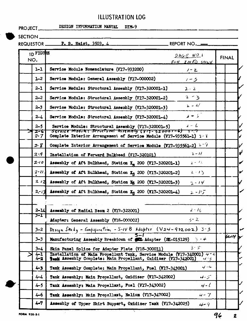
ILLUSTRATION LOG
PROJECT DESIGN INFORMATION MANUAL DIM-9
SECTION
REQUESTOR REPORT NO. --
I D FIGg
NO.
I-i Service Module Nomenclature (V17-933200)
i-2
7-2-
Service M_ule: General Assembly (Vl?-O00002) /-
Service Module: Structural Assembly (9-17-320001-1) i. Z
F INAL
2-1
2-2 Service Module: Structural Assembly (VI?-320001-2)
2-3 Service Module: Structural Assembly (V17-320001-3)
2-4 Service Module: Structural Assembly (V17-320001-4)
2-5 Service Module: Struc t_-al Assembly_ (V17-320001-5) z .-
C_mplete Interior Arrangement of Service Module (V17-935561-I) ;-
2- t_1,
Complete Interior Arrangement of Service Rodule
Installation of Forward Bulkhead (V17-_20101)
Assembly of Aft Bulkhead, Statiom _. 200 (_17-320201-i)
Assembly of Aft Bulkhead, Station _ 200 (V17-320201-2)
z-._/
l- /.,L
Z-I-_
_2 Assembly of Aft Bulkhead, Station XB 200 (_17-320201-3) _ - /V
_,'/3 Assembly of Aft Bulkhead, Station _ 200 (n7-320201-4) 2_ -',/'b-
2-14 Assembly of Radial Beam 2 (V17-322001) 2 -/_,
Adapter: General Assembly (V18-OOOOO2) _-2..
3-3 Manufacturing Assembly Breakdown of _ Adapter (_E-015129) -;;-,+
3-4>
4-s
_-4
Skin Panel Splice for Adapter Plate (V18-300011)
Installation of Maim Propellant Tank, Service Module (V17-340001) _-z.:_ Assembly Complete: Main Propellant, Oxidizer (VlT-3_l_O01J _ '_¢
Tank Assembly Complete: Main ProPellant _ Fuel (IF17-343001) _/"_¢
Tank Assembly: Main Propellant, Oxidiser (_17-342002) _ 5"
_-5 Tank Assembly, Main Propellant, Fuel (V17-343002)
4,.-6 Tank Assembly: Main Propellam%,. _elium (V17-347002)
A_sembly of Upper Skirt .Suppert, Oxidizer Tank (VlT-342025)

PROJECT
ILLUSTRATION LOG
DZ'!;I_-NI._'_(,=.:'.,;,TI','_'!"2_2._7AL DIM- 9
SECTION
REQUESTOR
I
NO.
P- 7_. t_.a_st 3503, .4 REPORT NO.
FINAL
Mo_mting Provisions, Znvir:m.'_enta! 3ontrc! System Instal]s.ticns (7].7-.55;71 7-"I
_-2 Mounting Provisions, Environmental Control System _nst,_.!]stions (_J!7-3-,J! 7-.2I
5-9 Molmting Provisions, Environmemtal Control System Installations (V3.7-_17 7":_.)
5-4 :-m_,_mb._ of Oxygen Tar_: Shelf Support (V17-331667)
5-5 Nodule InstalPation of Reaction Control System (V17-322000)
"9 ,. ,_4- " (_ . ......5-6 Panel Assembly 3omplete, ,_e_._ _l.m Control System (v17-33.2001-I)
5-7 Panel Asse_b!y Comolete, _*4c.n Control System (I_,-..j2001-_)
5-8 Pa_e]. Assemb2.y_ Peacticn Control System (F17-332002-I)
5-9 Panel Assemb_!y_ Peaction Ccntro! ._yst_m (V17:_.2OO2-2)
_-!O Housin_ Assembly, _....+_ o....... ......_ .n Control. Sys+.,_m (V!7-332010)
5-11 Longitudinal He_t Shield Instal].stion, .qe_ction Control System (7]..7-33:
5-].2 Lateral H_o.t Shield Installation, Reaction Control _vstem (VI7-_°_n]
5-]3 Insulation Imstallation for Reaction Control Systen,. (V17-3_2046)
5-1,/+ End M.ounti.-gAssembTy of Prooellant Tanks, Reaction Cen,<ro! System (7].5
5-].5 Motu_ting Assembly, Pro;._ellant and Pressure Tanks, Re cL_on C_t_o_
2ystem (V!7-332042)
5-16 Installation of _ _" *...._ngxne Mount, Service Propulsion oy_,,e_ ( V!7-3:_7101-I
"" _o,_ulsion Sv_t.__ (U!7-327!01-2)5-17 Installation of Engine No,mr, _er_ce . _. . .....
5-18. Mountin_ Provisions Installation, Service Propu!sJen Svst,_m (,l_-__.100(
5-19 }"..ounting_:'ovisions Installation, Service Pronu_--ion._.,_ _"_ssuriza1:.ion
System (717-331100)
r.,O ,_
)
0f:l)
--]
FORM 930- R-1
__;ou/uti_Provisions, Electrical Power System (V17-351552-I)
Mounting Provisions, Electrical Power System (V17-931552-2)l
/
!;"

PROJECT
SECTION
REQUESTOR
NO.
,o,. ,30 7
ILLUSTRATIONLOG
_IGN INFORMATION MANUAL DIM- 9
P. B. gaist. 3503. 4
| ,
i
REPORT NO,
Insta/lation of Fuel-Cell M_antlq, Stabilised Shear Web (VI?-33152_)
Assembly of Support Shelf, Upper R_rogen Tank (VI?-331566)
Control Layout - Electrical Power System Radiators, Seet_rs 0he and
FINAL
It
Four (V17-933074} _-"
Installation Previsions, Fluid Lines Support, Electrical Power _"
_ystem (_i?-331553-I)
Installation Provisions, Fluid Lines Support, Elee%rioal Power
System (VI?-331553-2)
Installation Provisions, Fluid Lines _ppert, _ee_ieal E_wer
Systen (v'z?-33z553.:.3)
0uter S_ell Assembly, Aft Heat Shleld, Seekers Three F_Ar and Five
Inner ShellAssembly, A_ Heat Shield, Se@ters Three and Fi_
)
Installation. of Aft Heat Shield, Station 200 (T17-331689-I)
InstaAlation of Aft Heat Shield, Statian 200 (V17-331689-2)
Insulation Installa_zon Pr_isions, Servlse Mule _rI?-331562-1)
Insulation _,stalla_Ion Provisions, Ser_Ise M_le (_17-33156_-2)
Complete Assembly of Thermal Simulator for Speoi_en Test _TT-6600)
Installation of Fairing (VI?-310001-1) 7- 2_
Installation of Fairing (_I?-31000_-2) 7-9
Fairing Panel Assembly, Serviee M_ule te Comad _ule (V17-311001)
Fairiag Assembly Complete, C_ma_ M_ule to Series R_4_I_ U_billeal
Strap-Tension Tie, Service _ule to _dapter (V18-300_05) _-7