Embed Size (px)
Citation preview
8/7/2019 Apollo Command Module Land-Impact Tests
http://slidepdf.com/reader/full/apollo-command-module-land-impact-tests 1/61
T E C H N IC A L N O T E
J. E . McCzlllozcgh and J. F. Lands, Jr.
Spacecrafi Center
Texas 77058
TIO NA L AERONAUTICS AN D SPACE ADMI NISTR ATION WASHING TON, D . C. OCTOBER.1972
8/7/2019 Apollo Command Module Land-Impact Tests
http://slidepdf.com/reader/full/apollo-command-module-land-impact-tests 2/61
1. Report No. 2. Government Accession No.
NASA TN D-69794. Title and Subtitle
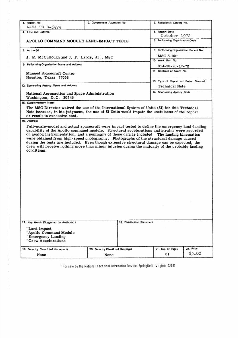
APOLLO COMMAND MODULE LAND-IMPACT TESTS
3. Recipient's Catalog No.
5. Reoort Date
October 1972.~ --
6. Performing Organization Code
7. Authodsl
J. E. McCullough and J. F. Lands, Jr . , MSC
9. Performing Organization Name and Address
14. Sponsoring Agency CodeNational Aeronautics and Space Administration
Washington, D. C. 20546
The MSC Director waived the use of the Inte rnational System of Units (SI) for this Technical
Note because, in his judgment, the use of SI Units would impair the usefulne ss of the repo rtor result in excessive cost.
15. Supplementary Notes
8. Performing Organization Report No.
MSC S-30110. Work Unit No.
9 14- 50-20- 17- 72
16. Abstract
Full-scale-model and actual spa cecra ft were impact tested to define the emergency land-landingcapability of the Apollo command module. Structural accelerations and st ra in s were re cordedon analog instrumentation, and a summary of these data is included. The landing kinematicswe re obtained fr om high-speed photography. Photographs of the st ruc tur al damage causedduring the te st s a r e included. Even though extensive structur al damage can be expected, thecrew will rece ive nothing mor e than minor inj uries during the majority of the probable landingconditions.
Manned Spacecraft CenterHouston, Texas 77058
12. Sponsoring Agency Name and Address
11. Contract.or Grant No.
13. Type of Report and Period Covered
Technical Note
17. Key Words (Suggested by Author(s))
* Land Impact.Apollo Command Module' Emergency Landing'Crew Accelerations
* F or s a le by t he N a t i ona l T ec hn ic a l I n f orm a t ion Serv i c e , Sp r i ng f i e l d , V i rg in ia 22151
18. Distribution Statement
I
19. Security Clanif. (of this report) ' 20. Security Classif. (of this page) 21. NO. of pages 22. Price
None None 6 1 $3.002
8/7/2019 Apollo Command Module Land-Impact Tests
http://slidepdf.com/reader/full/apollo-command-module-land-impact-tests 3/61
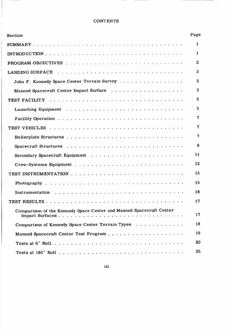
CONTENTS
. . . . . . . . . . . . . . . . . . . . . . . . . . . . . . . . . . . . .
. . . . . . . . . . . . . . . . . . . . . . . . . . . . . . . . . .. . . . . . . . . . . . . . . . . . . . . . . . . . . . .
. . . . . . . . . . . . . . . . . . . . . . . . . . . . . . .
John F . Kennedy Space Center Terrain Survey . . . . . . . . . . . . . . . .
Manned Spacecraft Center Impact Surface . . . . . . . . . . . . . . . . . .
. . . . . . . . . . . . . . . . . . . . . . . . . . . . . . . . .
Launching Equipment . . . . . . . . . . . . . . . . . . . . . . . . . . . . .
Facility Operation . . . . . . . . . . . . . . . . . . . . . . . . . . . . . . . .
. . . . . . . . . . . . . . . . . . . . . . . . . . . . . . . . .
Boilerplate Structures . . . . . . . . . . . . . . . . . . . . . . . . . . . . .
Spacecraft Structure s . . . . . . . . . . . . . . . . . . . . . . . . . . . . .
Secondary Spacecraft Equipment . . . . . . . . . . . . . . . . . . . . . . .
Crew-Systems Equipment . . . . . . . . . . . . . . . . . . . . . . . . . . .
INSTRUMENTATION . . . . . . . . . . . . . . . . . . . . . . . . . . . . .
Photography . . . . . . . . . . . . . . . . . . . . . . . . . . . . . . . . . .
Instrumen t ation . . . . . . . . . . . . . . . . . . . . . . . . . . . . . . . .
. . . . . . . . . . . . . . . . . . . . . . . . . . . . . . . . . .
Comparison of the Kennedy Space Center and Manned Spacecraft Center
Impact Surfaces . . . . . . . . . . . . . . . . . . . . . . . . . . . . . . .
Comparison of Kennedy Space Center Terrain Types . . . . . . . . . . . .
Manned Spacecraft Center Test Program . . . . . . . . . . . . . . . . . . .
Tests at 0" Roll . . . . . . . . . . . . . . . . . . . . . . . . . . . . . . . .
Tests at 180" Roll . . . . . . . . . . . . . . . . . . . . . . . . . . . . . . .
Page
1
1
2
3
3
3
5
5
7
7
7
a
11
12
15
15
16
17
17
18
19
20
25
iii
8/7/2019 Apollo Command Module Land-Impact Tests
http://slidepdf.com/reader/full/apollo-command-module-land-impact-tests 4/61
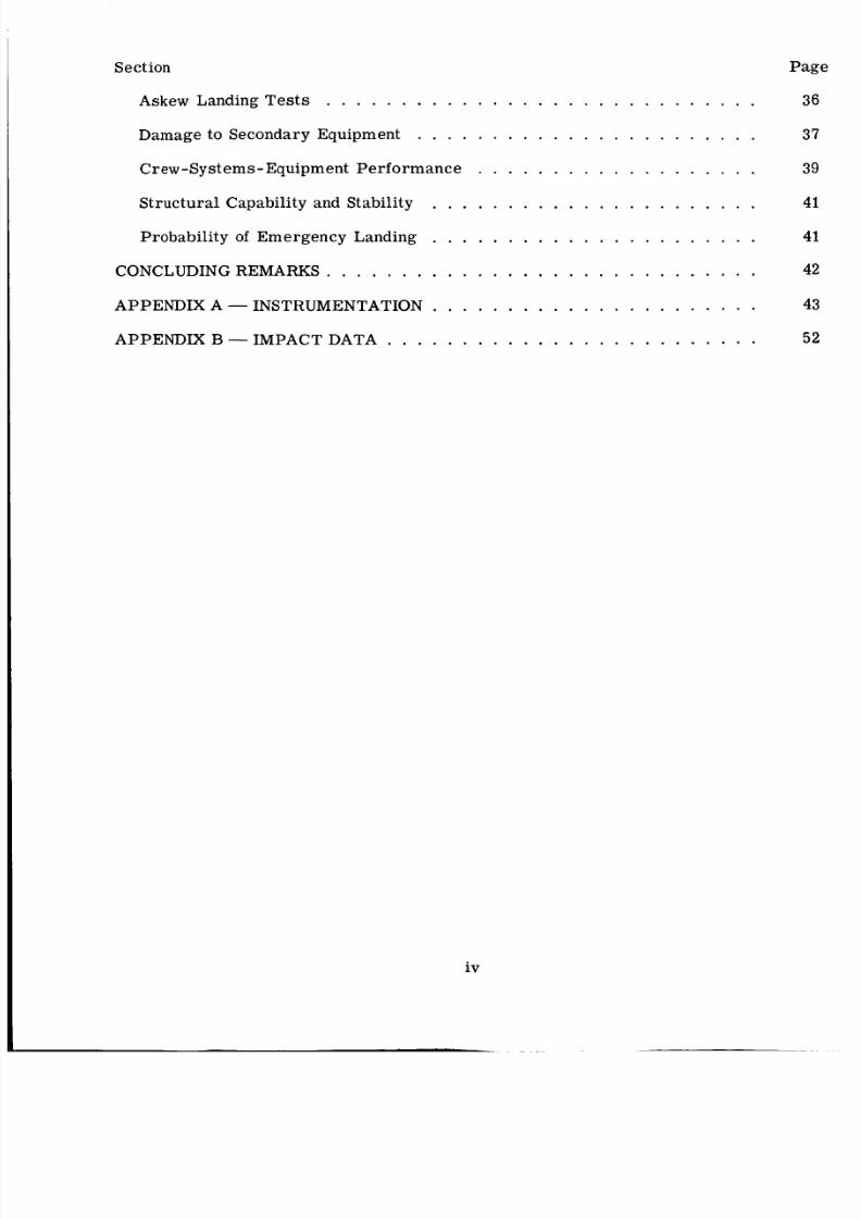
Sect on
Askew Landing Tests . . . . . . . . . .
Damage to Secondary Equipment . . . .
Crew-Systems-Equipment Performance
Struc tura l Capability and Stability . . .
Probability of Emergency Landing . . .
CONCLUDING REMARKS . . . . . . . . . .
APPENDIX A- NSTRUMENTATION . . .
APPENDIX B- MPACT DATA . . . . . .
Page
. . . . . . . . . . . . . . . . . . . 36
. . . . . . . . . . . . . . . . . . . 37
. . . . . . . . . . . . . . . . . . . 39
. . . . . . . . . . . . . . . . . . . 41
. . . . . . . . . . . . . . . . . . . 41
. . . . . . . . . . . . . . . . . . . 42
. . . . . . . . . . . . . . . . . . . 43
. . . . . . . . . . . . . . . . . . . 52
iv
8/7/2019 Apollo Command Module Land-Impact Tests
http://slidepdf.com/reader/full/apollo-command-module-land-impact-tests 5/61
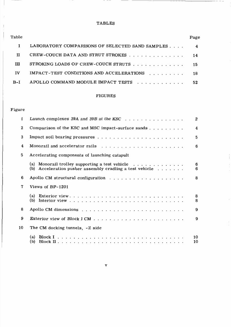
TABLES
Table Page
I LABORATORY COMPARISONS O F SELECTED SAND SAMPLES . . . . 4
I1 CREW-COUCH DATA AND STRUT STROKES . . . . . . . . . . . . . . 14
I11 STROKING LOADS OF CREW-COUCH STRUTS . . . . . . . . . . . . . 15
IV IMPACT-TEST CONDITIONS AND ACCELERATIONS . . . . . . . . . 18
B-I APOLLO COMMAND MODULE IMPACT TESTS . . . . . . . . . . . . 52
FIGURES
Figure
1 Launch complexes 39A and 39B at the KSC . . . . . . . . . . . . . . . 2
4Compari son of the KSC and MSC impact- surface sand s . . . . . . . . .
6
7
8
9
10
Impact soil bearing press ure s . . . . . . . . . . . . . . . . . . . . . . 5
Monorail and acce lerat or rails . . . . . . . . . . . . . . . . . . . . . 6
Acce lera ting components of launching catapult
66
8
(a) Monorail trolley supporting a test vehicle . . . . . . . . . . . . .(b) Acceleration pusher asse mbly cradling a test vehicle . . . . . . .
Apollo CM structural configuration . . . . . . . . . . . . . . . . . . .
Views of BP- 120
(a) Exterior view. 8(b) Int eri or view 8
9
. . . . . . . . . . . . . . . . . . . . . . . . . . . .. . . . . . . . . . . . . . . . . . . . . . . . . . . . .
Apollo CM dimensions . . . . . . . . . . . . . . . . . . . . . . . . . .
9xterior view of Block I CM . . . . . . . . . . . . . . . . . . . . . . .
The CM docking tunnels, - Z side
1010
(a) Block1 . . . . . . . . . . . . . . . . . . . . . . . . . . . . . . . .( b ) B l o c k I I . . . . . . . . . . . . . . . . . . . . . . . . . . . . . . . .
V
8/7/2019 Apollo Command Module Land-Impact Tests
http://slidepdf.com/reader/full/apollo-command-module-land-impact-tests 6/61
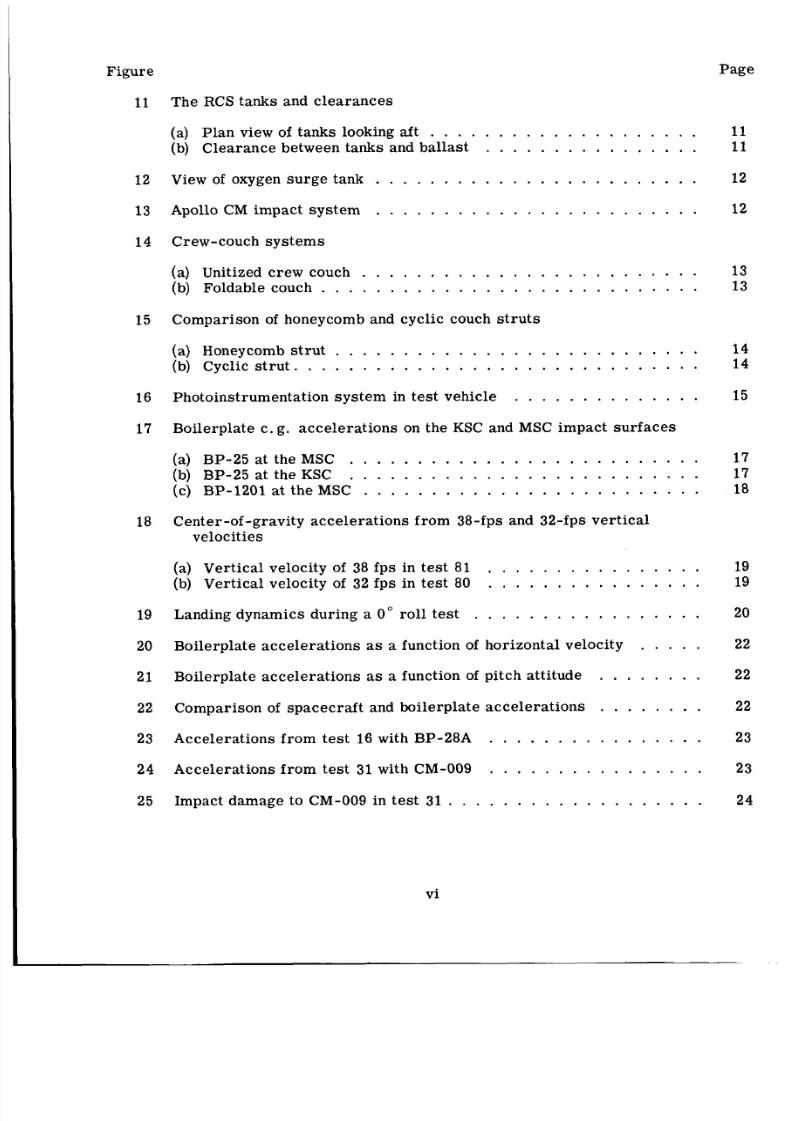
Figure Page
11 The RCS tanks and c leara nces
(a) Plan view of tanks looking af t . . . . . . . . . . . . . . . . . . . . 11(b) Clea rance between tanks and balla st . . . . . . . . . . . . . . . . 11
1 2 View of oxygen surge tank . . . . . . . . . . . . . . . . . . . . . . . . 12
13 Apollo CM imp act syst em . . . . . . . . . . . . . . . . . . . . . . . . 12
1 4 Crew-couch systems
(a) Unitized crew couch . . . . . . . . . . . . . . . . . . . . . . . . . 13
(b) Foldable couch . . . . . . . . . . . . . . . . . . . . . . . . . . . . 13
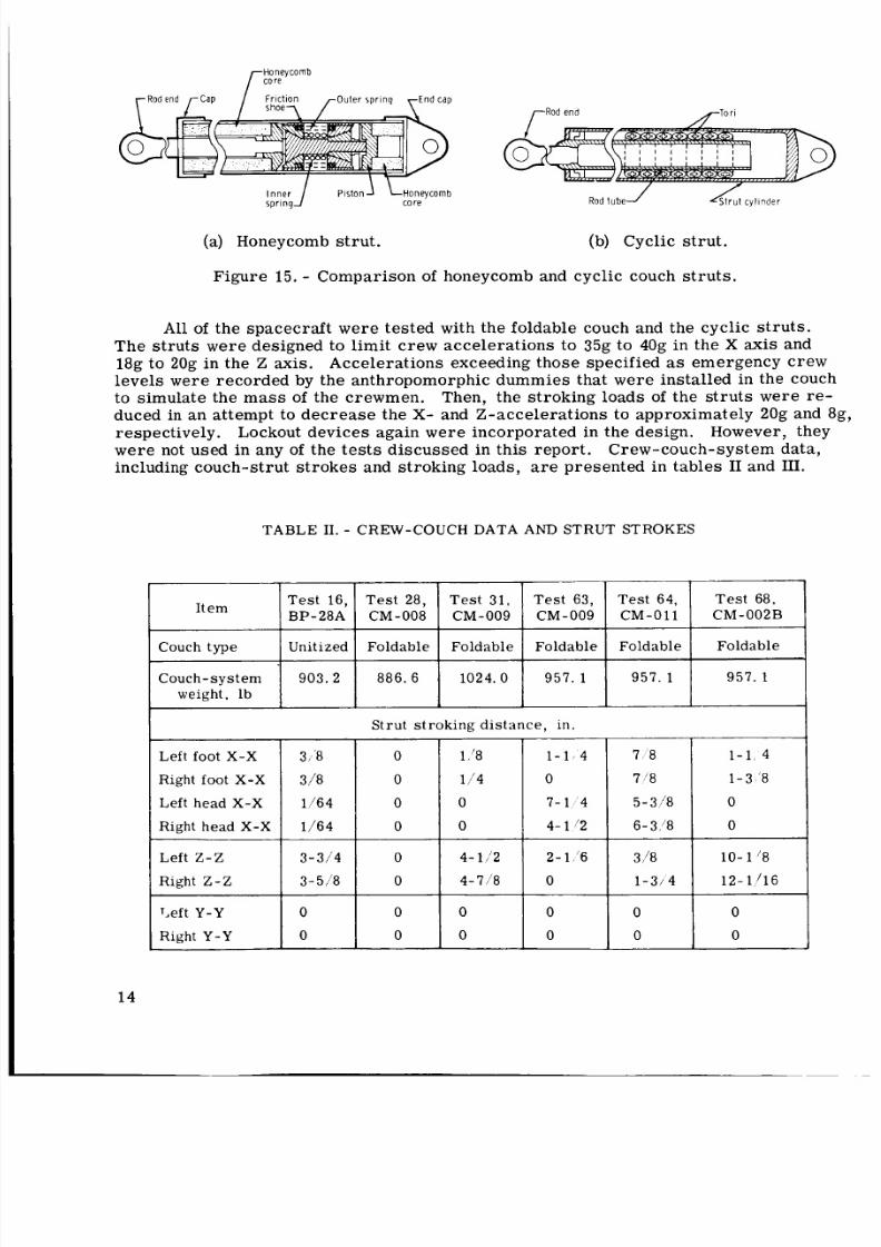
15 Compari son of honeycomb and cycl ic couch st ru ts
(a) Honeycomb str ut . . . . . . . . . . . . . . . . . . . . . . . . . . . 14
(b) Cyclic st ru t . . . . . . . . . . . . . . . . . . . . . . . . . . . . . . 14
156 Photoinstrumentation syste m in tes t vehicle . . . . . . . . . . . . . .
17 Boilerplate c . g. acc ele rat ion s on the KSC and MSC impact sur fa ces
(a) BP-25 at the MSC . . . . . . . . . . . . . . . . . . . . . . . . . . 17
(b) BP-25at theKSC . . . . . . . . . . . . . . . . . . . . . . . . . . 17
(c) BP-1201 at the MSC . . . . . . . . . . . . . . . . . . . . . . . . . 18
18 Center-of -gravity accelera tions from 38-fps and 32-fps verti calvelocities
(a) Ver tical velocity of 38 fps in te st 81 . . . . . . . . . . . . . . . . 19
(b) Verti cal velocity of 32 fps in te st 80 . . . . . . . . . . . . . . . . 19
19 Landing dynamics dur ing a 0" roll test . . . . . . . . . . . . . . . . . 20
20 Boilerplate accel erati ons as a function of horizontal velocity . . . . . 22
2 1 Boilerplate accelerations as a function of pitch att itude . . . . . . . . 22
22 Comparison of space craft and boilerplate acc elera tions . . . . . . . . 22
23 Accelerations fr om te st 16 with BP-28A . . . . . . . . . . . . . . . . 23
24 Accelerations fro m test 31 with CM-009 . . . . . . . . . . . . . . . . 23
25 Impact damage to CM-009 in test 31 . . . . . . . . . . . . . . . . . . . 24
vi
8/7/2019 Apollo Command Module Land-Impact Tests
http://slidepdf.com/reader/full/apollo-command-module-land-impact-tests 7/61
Figure
26
27
28
29
30
31
32
33
34
35
36
37
38
39
40
4142
43
44
45
46
47
A- 1
Page
Fac tor s in the dynamics of a CM landing
(a) Landing at 0" roll . . . . . . . . . . . . . . . . . . . . . . . . . . 25(b) Landing at 180" rol l . . . . . . . . . . . . . . . . . . . . . . . . . 25
Theoretical trajectory of CM c .g. during a 180" roll impact . . . . . . 26
Landing dynamics of CM-008 dur ing te st 28 . . . . . . . . . . . . . . . 27
Impact damage to CM-008 . . . . . . . . . . . . . . . . . . . . . . . . 27
Landing dynamics of CM-009 during tes t 63 . . . . . . . . . . . . . . . 29
Damage to CM-009 during a 180" ro ll landing . . . . . . . . . . . . . . 30
32
Impact damage to CM-011 . . . . . . . . . . . . . . . . . . . . . . . . 32
Accelerations at c .g. recorded during test 28 with CM-008 . . . . . . 34
Landing dynamics of CM-011 during test 64 . . . . . . . . . . . . . . .
Boilerplat e c.g. acce lera tions under conditions of tes t 28 . . . . . . . 34
Accelerations at c .g . during test 63 with CM-009 . . . . . . . . . . . . 34
Boilerplate acc elerations at c .g. under conditions of test 63
Accelerations at c .g. during t es t 64 with CM-011 . . . . . . . . . . . .
. . . . . . 35
35
Boilerplate accelerations under conditions of test 64 . . . . . . . . . . 36
36ccele rat ions re corded dur ing te st 68 with CM-OO2B . . . . . . . . . .
Boilerplate accel era tio ns under conditions of t es t 68 . . . . . . . . . .
Landing dynamics of CM-002B dur ing test 68 . . . . . . . . . . . . . .
Damage to CM-OO2B in test 68 . . . . . . . . . . . . . . . . . . . . . .
Typical impact da mage to RCS tanks . . . . . . . . . . . . . . . . . . .Accelerations in the X axis during tes t 31 with CM-009 . . . . . . . . .
Accelerations in the X axis during test 64 with CM-011 . . . . . . . . .
Land-landing capability as a function of ro l l angle of a CM . . . . . . .
Locations of acce lerom eter s and stroke indicators for test 16 withBP-28A . . . . . . . . . . . . . . . . . . . . . . . . . . . . . . . . .
36
37
37
38
40
40
41
43
vii
8/7/2019 Apollo Command Module Land-Impact Tests
http://slidepdf.com/reader/full/apollo-command-module-land-impact-tests 8/61
Pageigure
A-2
A- 3
A-4
A- 5
A- 6
A- 7
A-8
A-9
A- 10
A-11
A- 12
A- 13
A-14
A- 15
A- 16
A-17
A- 18
A- 19
A-20
Aft-sidewall stra in-g age locations fo r test 16 with BP-28A . . . . . . . 43
Deta ils of aft-sidewall str ain- gage locations for t es t 16 with
BP.28A . . . . . . . . . . . . . . . . . . . . . . . . . . . . . . . . . 44
Aft-sidewall st ra in gages at co re 2 for te st 16 with BP-28A . . . . . . 44
Aft-sidewall st ra in gages at co re 3 fo r te st 16 with BP-28A . . . . . . 44
Aft-bulkhead equipment and instrum enta tion fo r test 16 with
BP.28A . . . . . . . . . . . . . . . . . . . . . . . . . . . . . . . . . 44
Range-camera coverage for te st 16 with BP-28A . . . . . . . . . . . . 45
Locations of stru ctura l acce lero mete rs for test 28 with CM-008 . . . . 45
Instrumentation of foldable cre w couch and su pport sy ste m fo r tes t 28
with CM-008 and test 31 with CM-009 . . . . . . . . . . . . . . . . . 45
Locations of analog-re corded st ra in gages fo r tes t 28 with CM-008
(a) Inside view toward + Z . . . . . . . . . . . . . . . . . . . . . . . . 46(b) Inside view toward - Z . . . . . . . . . . . . . . . . . . . . . . . . 46
Locations and views of ran ge ca me ra s fo r test 28 with CM-008 . . . . 46
Locations of str uct ura l acc ele rom ete rs fo r te st 31 with CM-009 . . . . 47
Locations of s idewall- and aft-bulkhead st ra in gages for te st 31 with
CM.009 . . . . . . . . . . . . . . . . . . . . . . . . . . . . . . . . . 47
Locations of side- fram e st ra in gages fo r tes t 31 with CM-009 . . . . . 48
Locations of ran ge cameras fo r te st 31 with CM-009 . . . . . . . . . . 48
Structural accel erom eters f or tes t 63 with CM-009 and te st 64 with
CM.011 . . . . . . . . . . . . . . . . . . . . . . . . . . . . . . . . . 48
Crew-couch acc ele rom ete rs for t est 63 with CM-009 and te st 64 with
CM-011 . . . . . . . . . . . . . . . . . . . . . . . . . . . . . . . . . 48
Crew-couch str ut instrumen tation fo r te st 63 with CM-009 . . . . . . . 49
Locations of range ca me ra s fo r te st 63 with CM-009 . . . . . . . . . . 49
Crew-mu ch str ut instr umentatio n fo r test 64 with CM-011 and
test 68 with CM-OO2B . . . . . . . . . . . . . . . . . . . . . . . . . 50
viii
.
8/7/2019 Apollo Command Module Land-Impact Tests
http://slidepdf.com/reader/full/apollo-command-module-land-impact-tests 9/61
Figure
A - 2 1
A-22
A-23
A - 2 4
Page
Locations of range c am er as for te st 64 with CM-011 . . . . . . . . . . 50
Struc tural ac ce le rome te rs fo r tes t 68 with CM-OO2B . . . . . . . . . . 51
Crew-couch instrumentation for tes t 68 with CM-002B . . . . . . . . . 51
Locations of accel erom et er s in BP-1201 . . . . . . . . . . . . . . . . 51
8/7/2019 Apollo Command Module Land-Impact Tests
http://slidepdf.com/reader/full/apollo-command-module-land-impact-tests 10/61
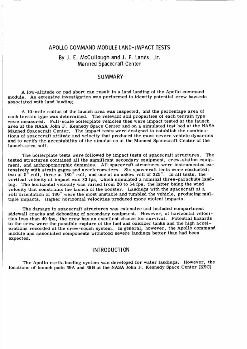
APOLLO COMMAND MODULE LAND-IMPACT TESTS
The boilerplate t es ts were followed by impact te st s of spacecraft struc tures . The
str uct ure s contained all the significant secondary equipment, crew-sta tion equip-
and anthropomorphic dummies. A l l spacecraft structu res were instrumented ex-
Six spac ecra ft tes ts w ere conducted:0 " roll, th re e at 180" roll, and one at a n askew rol l of 325". In all tests, the
at impact w a s 32 fps, which simulated a nominal three-parachute land-The horizontal velocity was varied from 20 to 54 fps , the l at te r being the wind
that constr ain s the launch of the booster. Landings with the spac ecr aft at all or ienta tion of 180" we re the most unstable and tumbled the vehicle, producing mul-
impacts. Higher horizontal velocities produced mo re violent impacts.
By J. E. McCuIlough and J . F. Lands, Jr.Manned Spacecraft Center
SUMMARY
A low-altitude o r pad abo rt can res ult in a land landing of the Apollo command
An extensive investigation w a s performed to identify potential crew hazards
A 10-mi le rad ius of the launch area w a s inspected, and the percentage a re a ofin type w a s determined. The relevant soil prope rties of each te rr ai n type
e meas ured. Full-scale boilerplate vehicles then were impact tested at the launchat the NASA John F. Kennedy Space Center and on a simulated test bed at the NASA
ned Spacecraft Center. The impact tests were designed to es tablish the combina-f spa cec raf t attitude and velocity that produced the most se ve re vehicle dynamics
ver ify the accep tabi lity of the simula tion at the Manned Spacecra ft Cen ter of t he
The damage to spacecraft st ructu res w a s extensive and included compartmentwall crac ks and debonding of secondary equipment. However, at horizontal veloci-
es le s s than 40 fps, the crew has an excellent chance for survival. Potential haza rds
at the crew-couch syste m. In general, however, the Apollo command
.
I NTRODUCT ION
The Apollo earth-landing syste m was developed for water landings. However, the
ca tions of launch pads 39A and 39B at the NASA John F. Kennedy Space Center (KSC)
8/7/2019 Apollo Command Module Land-Impact Tests
http://slidepdf.com/reader/full/apollo-command-module-land-impact-tests 11/61
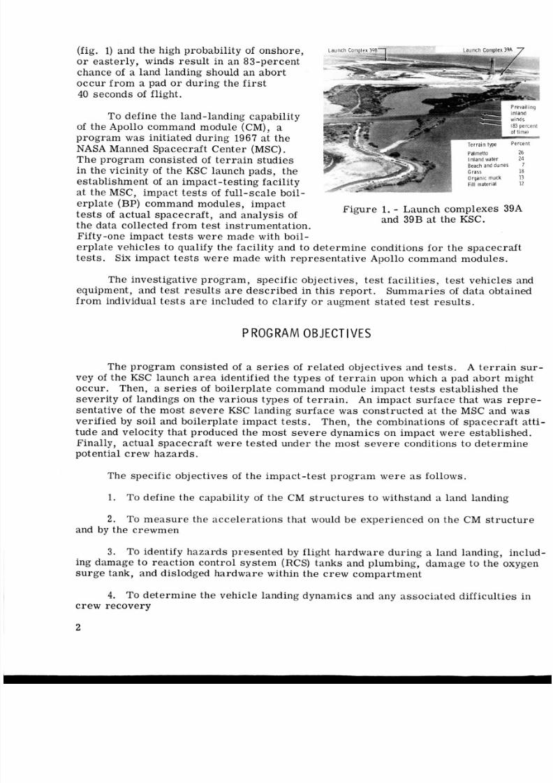
(fig. 1) and the high probability of onshore ,o r easterly, winds result in an 83-percent
chance of a land landing should an abor t
occur from a pad or during the first40 seconds of flight.
To define the land-landing capability
of the Apollo command module (CM), aprogram was initiated during 1967 at the
NASA Manned Spacecraft Center (MSC).The program consisted of te rr ai n studies
in the vicinity of the KSC launch pads, the
estab lishment of an impac t-test ing facil ity
at the MSC, impac t te s ts of full -sc ale boil-
erplate (BP) command modules, impac t
t es t s of actua l space craft , and analys is of
the data collected from test instrumentation.Fifty-one impact te st s wer e mad e with boil-
Beach and dunes 7
Organic muck 13FIII mater ia l 12
Figure 1. - Launch complexes 39Aand 39B at the KSC.
erplat e vehicles to qualify the facility and to dete rmi ne conditions for t he s pac ecr afttests . Six impact tests were made with representative Apollo command modules.
The investigative program , specific objectives, tes t faciliti es, tes t vehicles and
equipment, and tes t res ults a r e described in this report. Summa ries of data obtained
fro m individual te st s a r e included to clarify o r augment stated test results.
P ROG RAM O BJECTI VES
The program consisted of a se ri es of relate d objectives and tes ts. A t er ra in sur
vey of th e KSC launch ar ea identified the types of t er ra in upon which a pad abort mightoccur. Then, a series of boilerplate command module impact tests established the
sever ity of landings on the various types of te rr ai n. An impact sur fac e that w a s repre-
senta tive of th e most sev er e KSC landing surfac e w a s constructed at the MSC and w a sverified by soil and boilerplate impact te st s. Then, t he combinations of space craft atti
tude and velocity that produced the most se ve re dynamics on impact we re established.Finally, actual spacecraft were tested under the most s ev er e conditions to determine
potential crew hazards.
The specific objectives of the impa ct-tes t pro gra m we re as follows.
1. To define the capability of the CM s tr uc tu re s to withstand a land landing
2 . To me as ure the acc elera tions that would be experienced on the CM st ruc tu re
and by the crewmen
3. To identify haza rds pres ented by flight hard war e during a land landing, including damage to react ion control sys tem (RCS) tanks and plumbing, damage to the oxygen
su rge tank, and dislodged hardw are within the c rew compa rtment
4. To det erm ine the vehicle landing dynamics and any ass ociate d difficulties increw recovery
2
8/7/2019 Apollo Command Module Land-Impact Tests
http://slidepdf.com/reader/full/apollo-command-module-land-impact-tests 12/61
L A N D I N G SURFACE
J o h n F. K e n n e d y S pa ce C e n t e r T e r r a i n S u r v e y
To evaluate possible landing sit es, a fie ld study of t he KSC launch a re a was made
between October 2 and November 28, 1967. During the survey , the a re a was mapped,the relat ive proportions of soil and vegetation types were determ ined, and the crit ical
mechanical pro per tie s of the soil types were measured.
In the sit e survey, six basic types of terrain were identified.
and the rel ative proportions within the launch ar ea a re as follows.
The ter rai n types
Terra in type Area, percent
Palmetto
WaterGrass
Organic muck
Fill material
Beach and dunes
26
2 4
18
13
1 2
7
The palmetto te rr ai n was relatively dr y sand overgrown with thick underbrush andpalmetto vegetation. The water s it es were shallow-water ma rs he s and ponds. The
grass sites were sandy soi ls covered by salt grass 2 to 3 feet in height. The organic
muck occurred in tidewater marshes and w a s a s i l t y , quicksand type of so il with a highmois ture content and a low bearing strength. The f i l l material w a s a fine-grained sand
pumped fro m canals to rai se the surface level. When dry , this fill mate rial had a high
bear ing stren gth. The ar eas in the immediate vicinity of the launch pads wer e composed
of fill material. The last category, beach and dunes, was composed of loose, water-
washed o r wind-drifted sand. Because of the high bea ring strength , the fill material
w a s considered to be th e most formidable impact sur fac e on which a spacecraft couldland.
M a n n e d S p a c e cr af t C e n t e r I m p a c t S u r f a c e
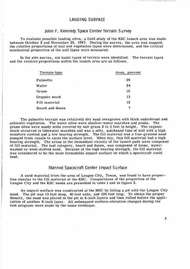
A sand material from the a rea of League City, Texas, w a s found to have proper -t ies s imilar to the f i l l material at the KSC. Comparisons of the prop ertie s of the
League City and the KSC sands a r e presented in table I and in figur e 2.
An impact surface w a s constructed at the MSC by filling a pit with the League City
sand. The pit w as 13 feet deep, 40 feet wide, and 100 feet long. To obtain the pro per
density, the sand was placed in the pit in 6-inch layers and then rolled before the appli-cation of anot her 6-inch laye r. All subsequent surface-eleva tion changes duri ng the
te st p rogra m were made by the s am e technique.
3
8/7/2019 Apollo Command Module Land-Impact Tests
http://slidepdf.com/reader/full/apollo-command-module-land-impact-tests 13/61
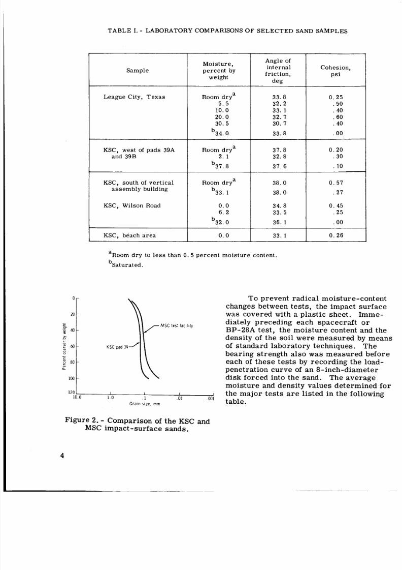
TABLE I. - LABORATORY COMPARISONS OF SELECTED SAND SAMPLES
I I
0 -
2 0 -
IS
P 40-
2-
.aL
c 6 0 -
0
CL
8 0 -0 )
loo -
7-
Sample
League City, Texas
KSC, west of pads 39Aand 39B
Moisture,percent by
weight
Room drya5 .5
10.0
20.030.5
b34. 0
aRoom dry
2 . 1
b37. 8
Angle ofinternalfriction,
deg
33.832. 2
33. 132. 730. 7
33.8
37.832. 8
37. 6
KSC, south of vert icalassembly building Room dryab33. 1
KSC, Wilson Road 0 . 06. 2
b32. 0
KSC, beach area 0 .0
38.038.0
34. 8
33. 5
36. 1
33.1
a
bSaturated.
Room dry to less than 0.5 percent moisture content.
120 1 I I I
10.0 1.0 . 1 .01 .001
Grain s i z e , mm
Cohesion,psi
0.25.50. 40.60. 40
.00
0.20.30
. 10
0.57.27
0.45.25
.00
0.26
To prevent ra dical moisture-content
changes between tests , the impact surfacew a s covered with a plastic sheet. Imme-
diately preceding each spacecraft o rBP-28A test, the moisture content and thedensity of the soi l wer e measur ed by meansof standard laboratory techniques. The
bearing strength als o w a s measured beforeeach of the se tes ts by recording the load-
penetration cur ve of a n 8-inch-diameterdisk forced into the sand. The aver age
moisture and density values determined forthe majo r te sts a r e listed in the following
table.
Figure 2. - Comparison of the KSC andMSC impact-surface sands.
4
8/7/2019 Apollo Command Module Land-Impact Tests
http://slidepdf.com/reader/full/apollo-command-module-land-impact-tests 14/61
Test-
5116
4116
.i 3116
ie
CL
2116
Vehicle
-- - i m i t of s c a t t e r b a n d .0 .
/
/-
-
-*-
-,Slope approximately 320 p s i l i n .
B a n d w i d t h a p p r o x i m a t e l y 60 p s i
16 BP-28A
28 CM-008
31 CM-009
63 CM-009
64 CM-011
Moisture content, percent
bv weight
8.36
11.96
10.80
9.96
9.80
Density, lb/ft3
122
127
123
125
125
- -8 CM-002B - -
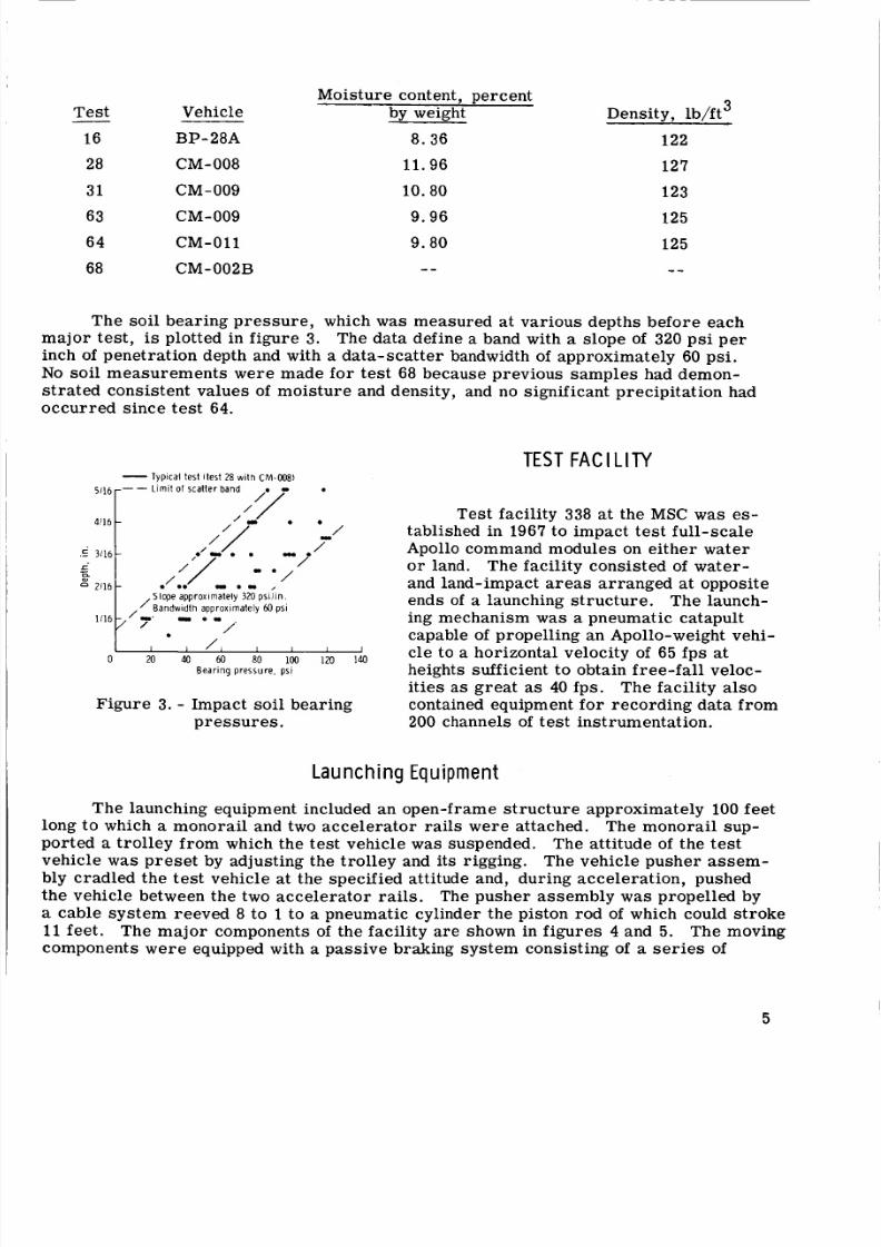
The soil bearing pre ssu re, which was measured at various depths before each
major test , is plotted in figur e 3. The data define a band with a slope of 320 ps i pe rinch of penetrat ion depth and with a data-scatter bandwidth of approximately 60 psi.
No soil measurements were made for test 68 because previous samples had demon-
st ra te d consistent values of m ois tur e and density, and no significant precipita tion had
occurred since test 64.
TEST F A C I L I T Y
Figure 3. - Impact soil bearing
pressures.
Test facility 338 at the MSC was es-tablished in 1967 to impact t est full -sca le
Apollo command modules on e ith er wateror land. The facility consisted of water -
and land-impact areas arranged at opposite
ends of a launching str uct ure . The launch-ing mechanism w a s a pneumatic catapult
capable of propel ling an Apollo-weight vehi-cle to a horizonta l velocity of 65 fp s atheights sufficient to obtain free-fall veloc-
i t ies as great as 40 fps. The facility al socontained equipment fo r reco rding data from
200 channels of test instrumentation.
La unch ng Equi me n
The launching equipment included an open-frame structure approximately 100 feetlong to which a monorail and two acc eler ator rail s were attached. The monorail sup-
ported a troll ey fr om which the tes t vehicle was suspended. The attitude of t he tes t
vehicle w a s preset by adjusting the trolley and its rigging. The vehicle pusher as sem -
bly cradled the te st vehicle at the specified attitude and, during accelera tion, pushed
the vehicle between the two acce lera tor rails. The pusher a ssem bly was propelled by
a cable system reeved 8 to 1 to a pneumatic cylinder the piston rod of which could st ro ke
11 feet . The ma jo r components of the facility a re shown in fig ure s 4 and 5. The moving
components we re equipped with a pass ive braking sy ste m consist ing of a se ri es of
5
8/7/2019 Apollo Command Module Land-Impact Tests
http://slidepdf.com/reader/full/apollo-command-module-land-impact-tests 15/61
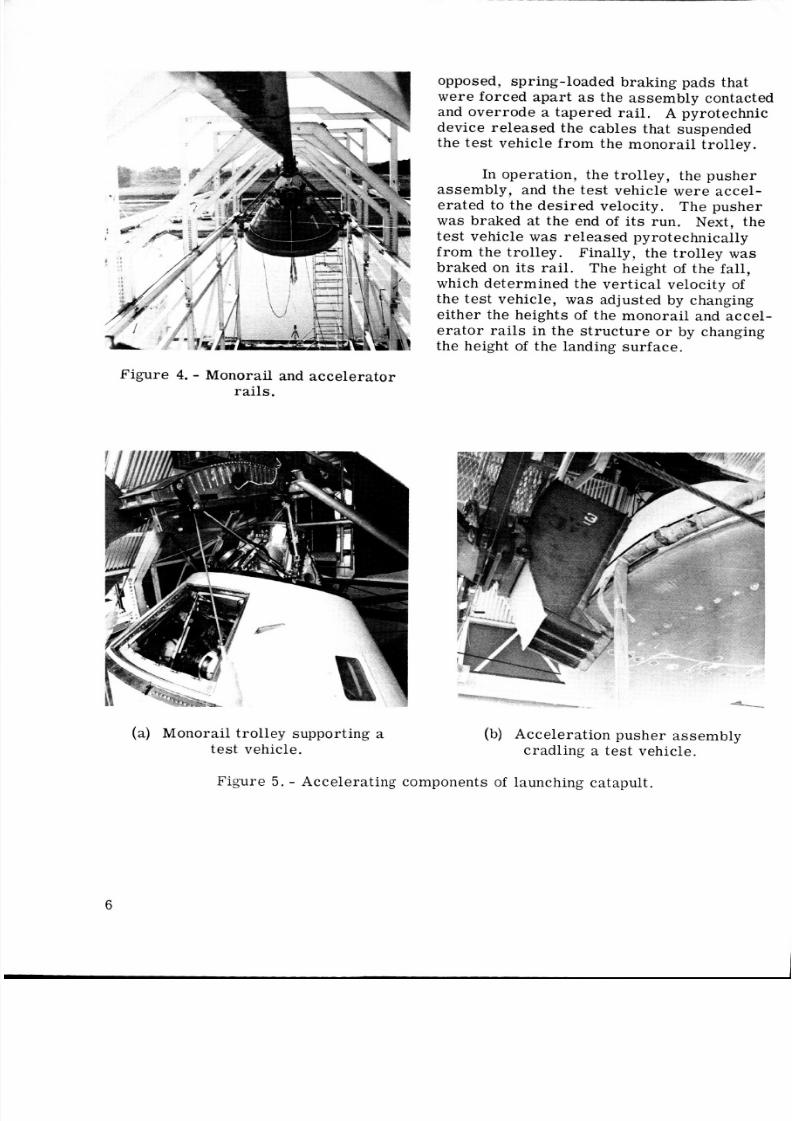
opposed, spring- loaded braking pads that
were forced apa rt as the ass emb ly contacted
and overrode a tapered rail. A pyrotechnicdevice released the cables that suspendedthe test vehicle from the monorail trolley.
In operation, the trolley, the pusherassembly, and the tes t vehicle wer e accel-
erated to the des ired velocity. The pusher
was braked at the end of it s run. Next, thete st vehicle was relea sed pyrotechnically
from the trolley. Finally, the trolley w a sbraked on its rail. Th e height of the fall,which de termin ed the ver tica l velocity of
the tes t vehicle, was adjus ted by changing
eit her the heights of the monora il and accel-
e ra to r rails in the st ructur e or by changingthe height of the landing surface.
Figure 4. - Monorail and accelerator
rails.
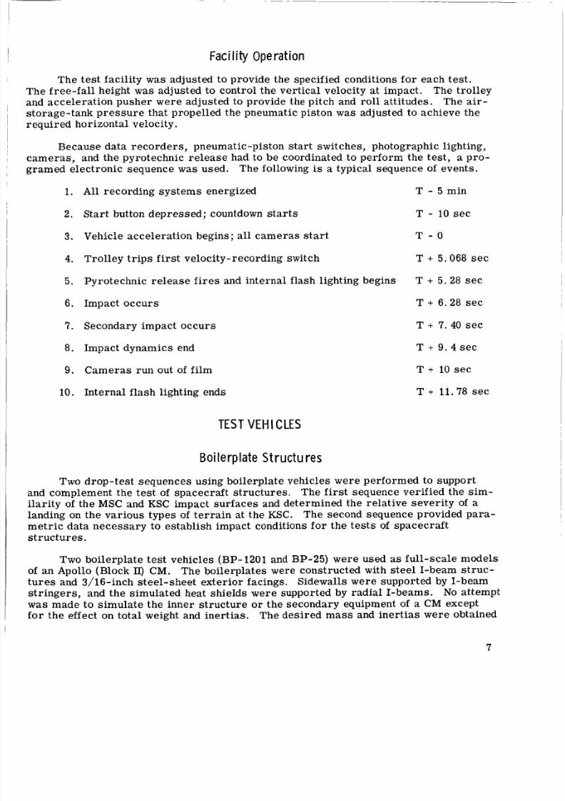
(a) Monorail trol ley supporting atest vehicle.
-ac__
(b) Accel eratio n pusher assemb ly
cradling a tes t vehicle.
Figure 5 . - Accele rat ing components of launching catapult.
6
8/7/2019 Apollo Command Module Land-Impact Tests
http://slidepdf.com/reader/full/apollo-command-module-land-impact-tests 16/61
F a c i l it y O p e r a t io n
The test facility w a s adjusted to provide the specified conditions f o r each te st .
The free -fa ll height w a s adjusted to control the vertical velocity at impact. The trolleyand acce lerat ion pusher we re adjusted to provide t h e pitch and roll attitudes. The air-storage-tank pr es su re that propelled the pneumatic piston w a s adjusted to achieve the
required horizontal velocity.
Because data recor der s, pneumatic-piston sta rt switches, photographic lighting,
cam era s, and the pyrotechnic rel ea se had to be coordinated to perform the test , a pro-
gramed electronic sequence w a s used. The following is a typical sequence of events .
1.
2.
3 .
4.
5.
6.
7.
8.
9.
10.
A l l recording syste ms energized
Star t button depr essed ; countdown st ar ts
Vehicle accelera tion begins ;all cameras s tar t
Trolley trips first velocity-recording switch
Pyrotechnic r el ea se fi re s and internal flash lighting begins
Impact occurs
Secondary impact occu rs
Impact dynamics end
Cameras run out of film
Internal flash lighting ends
T - 5 min
T - 10 se c
T - 0
T + 5.068 sec
T + 5.28 sec
T + 6.28 sec
T + 7.40 sec
T + 9 . 4 sec
T + 10 sec
T + 11.78 sec
TEST VEH ICLES
B o i l e r p l a t e Str u c t u r e s
Two drop-t est sequences using boilerplate vehicles we re performed to support
and complement the tes t of spacecra ft str uct ure s. The first sequence verified the si m-
ila rit y of th e MSC and KSC impact su rf ac es and determined the rela tive sev eri ty of alanding on the vari ous types of te rr ai n at the KSC. The second sequence provided pa ra -
me tr ic dat a nec ess ary to establish impact conditions for the te st s of spac ecra ft
s t ructures .
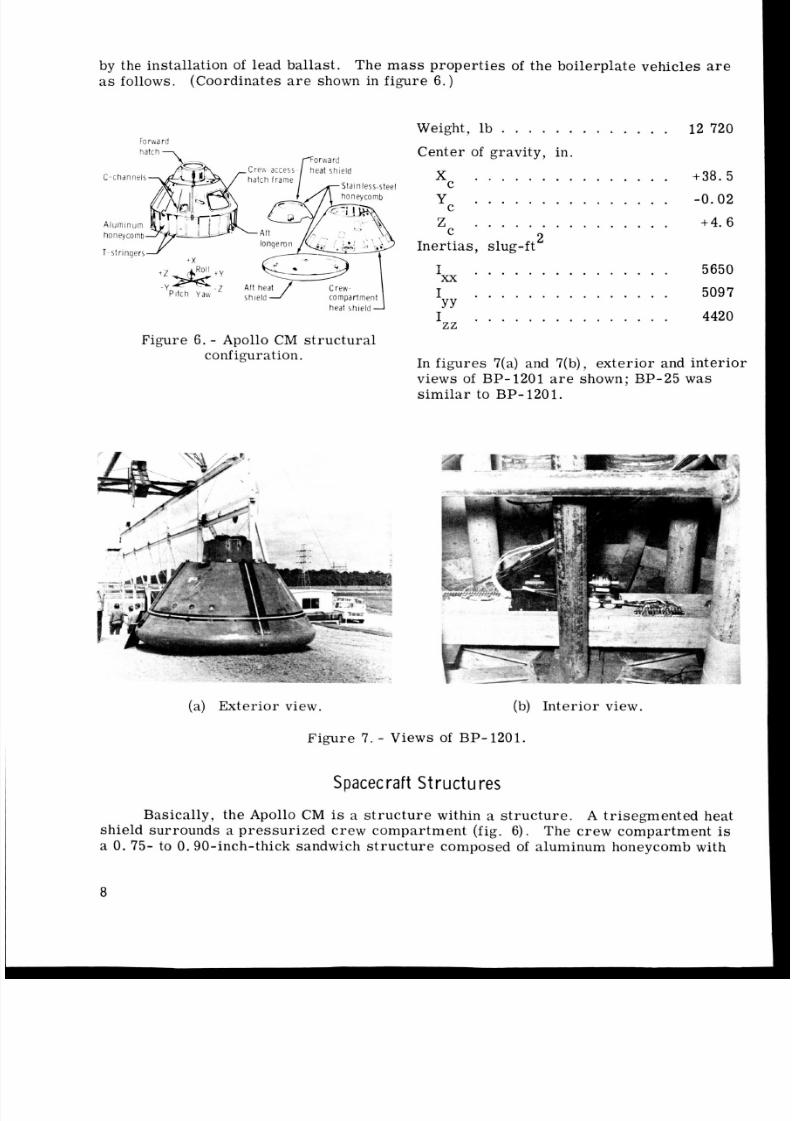
Two boilerplate test vehicles (BP-1201 and BP-25) were used as full-scale models
of an Apollo (Block 11) CM . The boilerplates were constructed with ste el I-beam st ru c-
tu re s and 3/16-inch steel -shee t ex terio r facings. Sidewalls were supported by I-beam
st ri ng er s, and the simulated heat shields were supported by radial I-beams. No attempt
w a s made to simulate the inner structu re or the secondary equipment of a CM exceptf o r the effect on total weight and inertias . The desi red ma ss and ine rti as were obtained
7
8/7/2019 Apollo Command Module Land-Impact Tests
http://slidepdf.com/reader/full/apollo-command-module-land-impact-tests 17/61
by the installation of lead ballast. The ma ss properties of the boilerplate vehicles areas follows. (Coordinates are shown in figure 6 . )
Forward
ha& CreLv access [Forwardea t shield
C-channels
/ -h at ch ' r a m - C I . , n l a r r ,
1-str ingers> iy
heat shield
Figure 6 . - Apollo CM structuralconfiguration.
(a) Exte rior view
Weight, lb . . . . . . . . . . . . . 12 720
Cen ter of gravity, in.
Xc . . . . . . . . . . . . . . . +38.5
Zc . . . . . . . . . . . . . . . +4.6
Ixx . . . . . . . . . . . . . . . 5650
I . . . . . . . . . . . . . . . 5097YY
Yc . . . . . . . . . . . . . . . -0.02
2Inertias, slug-ft
Izz . . . . . . . . . . . . . . . 4420
In figu res 7(a) and 7(b), ex teri or and inter iorviews of BP-1201 are shown; BP-25 was
sim ila r to BP- 1201.
(b ) Interior view.
Figure 7. - Views of BP-1201.
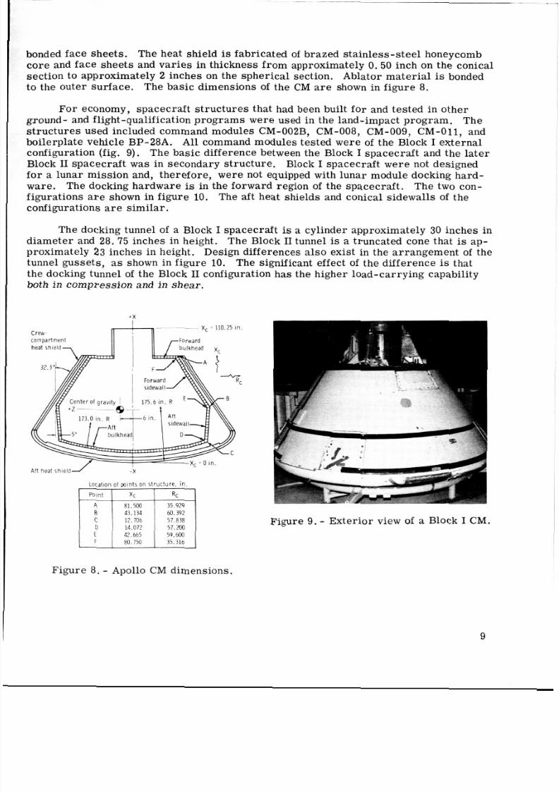
S p ac e cr a ft S t r u c t u r e s
Basically, the Apollo CM is a str uct ure within a stru cture . A trisegmented heat
shield surrounds a pressurized crew compartment (fig. 6). The crew compartment is
a 0. 75- to 0.90-inch-thick sandwich st ru c tu re composed of aluminum honeycomb with
8
8/7/2019 Apollo Command Module Land-Impact Tests
http://slidepdf.com/reader/full/apollo-command-module-land-impact-tests 18/61
8/7/2019 Apollo Command Module Land-Impact Tests
http://slidepdf.com/reader/full/apollo-command-module-land-impact-tests 19/61
(a) Block I. (b) Block 11.
Figure 10. - The CM docking tunnels , - 2 side.
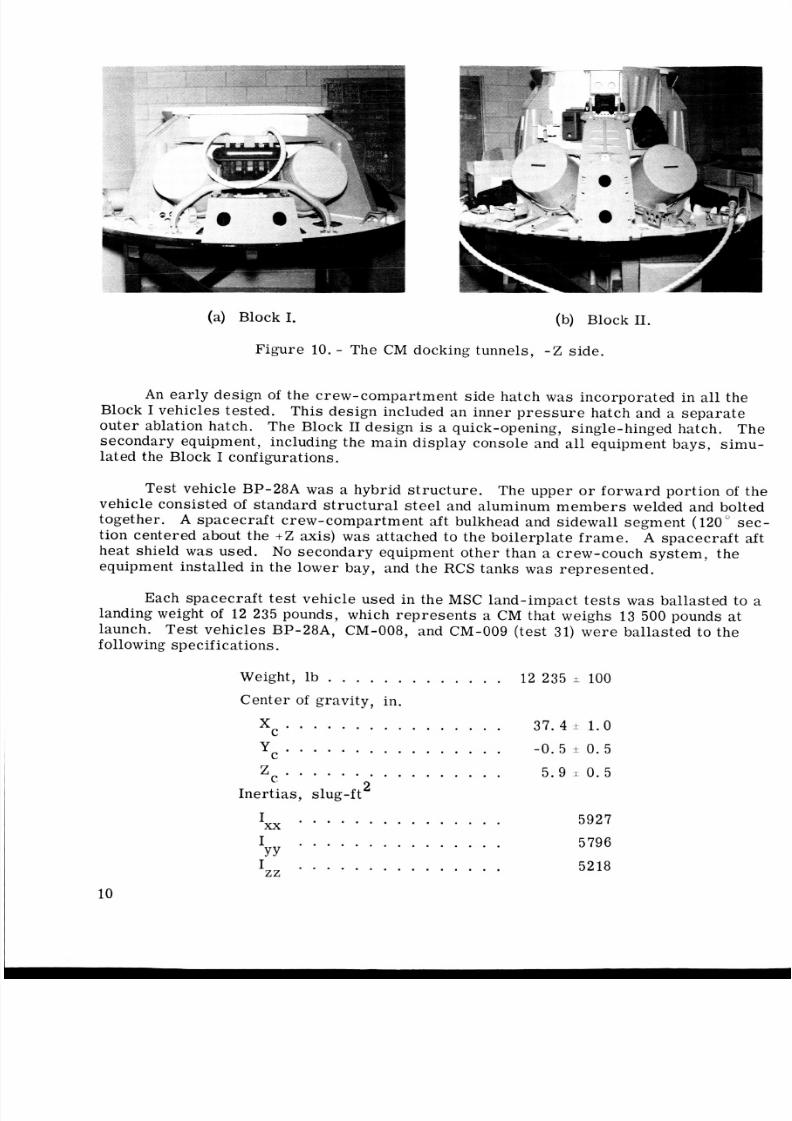
An ear ly design of the c rew-c ompart ment side hatch was in corpora ted in all the
Block I vehicles tested. This design included an inner pr es su re hatch and a separate
oute r ablation hatch. The Block I1 design is a quick-opening, single-hinged hatch. Th esecondary equipment, including the main display console and all equipment bays, simu-
lated the Block I configurations.
Test vehicle BP-28A was a hybrid structure. The upper o r forwar d portion of thevehicle consisted of s tandar d str uc tur al steel and aluminum m em be rs welded and bolted
together. A spa cec raf t crew-comp artme nt aft bulkhead and sidewall segme nt (120" se c-
tion centered about the +Z axis) was attached to the boilerplate fram e. A spacecraft aftheat shield w a s used. No seconda ry equipment othe r than a crew-couch system, theequipment ins talled in the lower bay, and the RCS tank s w a s represented.
Each sp acecr aft te st vehicle used in the MSC land-impact te st s was ballasted to alanding weight of 12 235 pounds, which repre sent s a CM that weighs 13 500 pounds a t
launch. Te st vehic les BP-28A, CM-008, and CM-009 (t es t 31) we re ballast ed to thefollowing specifications.
Weight, lb . . . . . . . . . . . . . 1 2 235 * 100
Center of gravity, in.
xc . . . . . . . . . . . . . . . . 37.4 * 1.0
Yc . . . . . . . . . . . . . . . . - 0 . 5 + 0.5
z . . . . . . . . . . . . . . . . 5.9 T 0 . 5
2Inertias, slug-ft
. . . . . . . . . . . . . . .xx 5927
I 5796YY
I 5218
. . . . . . . . . . . . . . .
. . . . . . . . . . . . . . .zz
10
8/7/2019 Apollo Command Module Land-Impact Tests
http://slidepdf.com/reader/full/apollo-command-module-land-impact-tests 20/61
In March 1968, new predictions of the center-of-gravity (c. g. ) location fo r the13 500-pound launch weight were made, and the remaining tes t s (CM-009 in te st 63,
CM-011, and CM-002B) were conducted with the vehicles bal las ted to the following
specifications.
Weight, lb . . . . . . . . . . . . .Cen ter of grav ity , in.12 235 *.lo0
X c . . . . . . . . . . . . . . . . 3 8 . 5 i 0 . 5
zc . . . . . . . . . . . . . . . . 4.7 i 0.5
I= . . . . . . . . . . . . . . . 5973
Y C . . " . . . . . . . . . . . . 0.0 * 0 .5
2Inertias, slug-ft
Secondaty Spacec ra f t Equ ipmen t
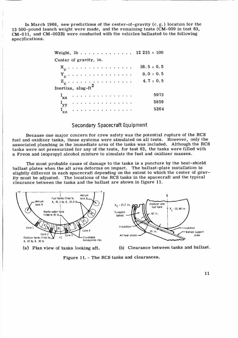
Because one major concern fo r crew safety w a s the poten tial rupture of t he RCSfuel and oxidizer tanks, these sys tem s were simulated on all te st s. However, only theassociat ed plumbing in the immediat e ar ea of th e tanks was included. Although the RCS
tanks wer e not pre ssu riz ed fo r any of the tes ts , f o r test 63, the tanks wer e filled with
a Freon and isopropyl alcohol mixture to simula te the fuel and oxidizer m ass es.
The most probable cau se of damage to the tanks is a puncture by the heat- shieldballast plates when the aft area defor ms on impact. The ballast-plate installation is
slightly different in each space craf t depending on the extent to which the center of grav-ity must be adjusted. The locations of the RCS tanks in the spacec raft and the typical
clea ranc e between the tanks and the ballast a r e shown in figur e 11.
F u e l t a n k s f i l l e d to: t a n k
A. 87 b: 8. 0 Ib h o n e y c o m b r i b s
\ \ \ . A? i n I I." L 1 1 1 .
Tungsten
b a l l a s t
I n s u l a t i o nI n s u l a t i o n
B a l l a s t s u p p o r t
p l a t ef t h e a t s h i e l d
(a) Plan view of tanks looking aft. (b) Clea ranc e between tanks and ballast.
Figure 11. - The RCS tanks and cle arances.
11
8/7/2019 Apollo Command Module Land-Impact Tests
http://slidepdf.com/reader/full/apollo-command-module-land-impact-tests 21/61
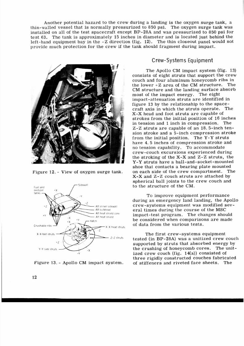
Another potential hazard t o the c rew during a landing is the oxygen sur ge tank, athin-walled ves sel that is normally pres suri zed to 850 psi. The oxygen sur ge tank wasinstalled on all of the te st spacec raft except BP-28A and was pres sur ize d to 850 ps i for
tes t 63. The tank is approximately 15 inches in dia met er and is located just behind the
left-hand equipment bay in the - Z direction (fig. 12) . The thin closeout pane l would notprovide much protection for the cre w if the tank should fragment during impact.
C rew -S y s t e m s Equ i rn e n
Figure 1 2 . - View of oxygen surge tank.
SidewallFuel an d
oxidizer + X
A f t inn er s idewa ll
Af t heat shield core
A f t heat shield
Y - Y side struts
- Y
Figure 13. - Apollo CM impact system.
The Apollo CM impact sys te m (fig. 13)cons ists of eight st ru ts that support the crew
couch and four aluminum honeycomb ribs inthe lower + Z a re a of the CM stru ctur e. The
CM st ruc tur e and the landing surf ace a bsor b
mos t of the impact ene rgy,
impact-attenuation struts are identified i nfigure 13 by the relationship to the space-
craft axis in which the st ru ts operate. TheX-X head and foot st ru ts a r e capable ofstr oke s from t he initial position of 16 inches
in tension and 1 inch in compres sion. The
Z - Z s t ru ts are capable of an 18. 5-inch ten-
sion st roke and a 5-inch compression stroke
fro m the initial position.
have 4 .5 inches of compres sion s tro ke and
no tension capability. To accommodate
crew-couch excursions experienced during
the s tro king of t he X-X and Z - Z struts , the
Y-Y t uts have a ball-and-socket -mounted
shoe that contacts a bearing plate mountedon eac h sid e of the crew compartment. The
X-X and Z - Z couch s tr ut s a r e attached by
sphe rica l ball joints to the c rew couch andto the st ruc tur e of the CM.
The eight
The Y-Y s t ru ts
To improv e equipment performance
during an emergency land landing, the Apollo
crew-systems equipment w a s modified sev-er al ti me s during the cou rse of t he MSC
impact -test program. The changes should
be considered when comparison s a r e made
of da ta from the various test s.
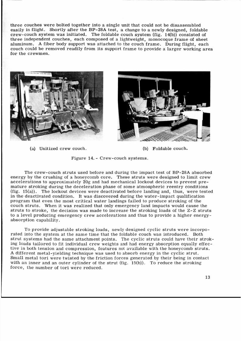
The first crew- system s equipmenttest ed (in BP-28A) was a unitized crew couch
supported by s tr ut s that absorbed energy bythe crush ing of honeycomb co re s. The unit-
ized crew couch (fig. 14(a))consisted ofthree rigidly constructed couches fabricated
of stif fene rs and riveted fac e she ets. The
12
8/7/2019 Apollo Command Module Land-Impact Tests
http://slidepdf.com/reader/full/apollo-command-module-land-impact-tests 22/61
re e couches were bolted together into a single unit that could not be disasse mble deasily in flight. Shortly af ter the BP-28A test , a change to a newly designed, foldablecrew-couch sys tem was initiated. The foldable couch syst em (fig. 14(b)) cons isted of
a lightweight, monocoque frame of sheet
luminum. A fib er body support was attached to the couch fr am e. During flight, each
couch could be removed readily f rom it s support fr am e to provide a large r working are a
the crewmen.
(a) Unitized crew couch. (b) Foldable couch.
Figure 14. - Crew-couch systems.
The crew-couch st ru ts used before and during the impact tes t of BP-28A absorbedener gy by the c rushi ng of a honeycomb core . These stru ts were designed to limi t crewaccelerations to approximately 20g and had mechanical lockout devices to prevent pre-
ma tur e stroki ng during the deceleration phase of some atmospheric ree ntry conditions
(fig. 15(a)). The lockout devices were deactivated befor e landing and, thus, we re testedin the deactivated condition. It w a s discovered during the wa ter-impact qualification
ro gra m that even the most crit ical water landings failed to produce stroking of thecouch st ru ts . When it w a s realized that only emergency land impacts would cause the
st ru ts to str oke , the decision was made to incre ase the stroking loads of the Z - Z s t ru ts
to a level producing emergency c rew a ccelerat ions and thus to provide a higher energy-
absorption capability.
To provide adjustable stroking loads, newly designed cyclic st ru ts we re incorpo-rate d into the s yst em a t the s am e time that the foldable couch w a s introduced. Both
str ut s yst ems had the sam e attachment points. The cyclic stru ts could have their strok -
ing loads ta ilo red to fit individual c rew weights and had energy absorption equally effec-tive in both tension and compression, features not available with the honeycomb struts.
different metal-yielding technique w a s used to abso rb energy in the cyclic str ut.Small meta l to ri were twisted by the friction forces generated by the ir being in contact
with an inner and an outer cylinder of the s tr ut (fig. 15(b)). To reduc e the strokin go rc e, the number of to ri were reduced.
13
8/7/2019 Apollo Command Module Land-Impact Tests
http://slidepdf.com/reader/full/apollo-command-module-land-impact-tests 23/61
I n n e r1 P i s t o n _I L H o n e y c o m b
s p r i n g co re
r R o d e n d /Tori
Ro d t u b e 1 d r u t c y l i n d e r
(a) Honeycomb st ru t. (b) Cyclic st ru t.
Figure 15 . - Comparison of honeycomb and cyclic couch str ut s.
All of the spa cecraft were tested with the foldable couch and the cyclic str uts .
The st ruts were designed to limit crew accelerations to 3 5 g to 40g in the X axis and
1 8 g to 20g in the Z axis. Accelera tions exceeding those specified as emergency crewlevels were recorded by the anthropomorphic dummies that were installed in the couch
to simulate the ma ss of the crewmen . Then, the stroking loads of the struts were re-duced in an attempt to decreas e the x- nd Z-accelerations to approximately 20g and 8g,
respectively. Lockout devices again wer e incorporated in the design. However, they
wer e not used in any of the te s ts discus sed in thi s re por t.including couch-strut str oke s and stroking loads, a r e presented in tables I1 and 111.
Crew-couch-system data,
TABLE 11. - CREW-COUCH DATA AND STRUT STROKES
Test 16, Tes t 28, Tes t 31. Test 63, Test 64, Test 68.BP-28A CM-008 CM-009 CM-009 CM-011 CM-OO2Btem
Couch type Unitized Foldable Foldab le Foldable Foldab le Foldab le
Couch-system 903. 2 886 .6 1024.0 957. 1 957.1 957.1
weight. lb
Strut stroking dist ance , in.
Left foot X -X 3, 8 0 1 '8 1- 1 4 7 8 1-1 4
Left head X -X 1/64 0 0 7-1 4 5- 3 18 0Right head X -X 1/64 0 0 4- 112 6-3 '8 0
Right foot X -X 3/8 0 1/ 4 0 7 '8 1-3 8
Left Z - Z 3-3/4 0 4- 1 / / 2 2 - 1 '6 3 '8 10- 1'8
Right Z -Z 3-518
1,eft Y -Y 0 0 0 0 0 0
0 4-718 0 1-3/ 4 12-1/16
Right Y -Y 0 0 0 0 0 0I -
1 4
8/7/2019 Apollo Command Module Land-Impact Tests
http://slidepdf.com/reader/full/apollo-command-module-land-impact-tests 24/61
TABLE 111. - STROKING LOADS OF CREW-COUCH STRUTS
-
Strut
location
Left foot X-X
Loads, lb
Te s t 16 Te s t 28 Test 31 Te s t 63
Design Actual Design Actual Design Actual Design Actual
7875 10 600 10 00 0 6250 6 00 0 (a) 4960 5200
Right foot X-X 7875 11 500 7 500 4720 4 400 9 670 49 50
Left head X-X 1 5167 1 3 440 I 6 00 0 1 5400 1 10 00 0 1 4 560 1 lii: 1 4200
Test 64
Design Actual
4960 5700
4230 4400
3660 4000
3089 4000
3750 3200
3320 4000
8170 0
8170 0
T e s t 68
Design Actual
5975 6950
5316 6100
4292 2370
3874 3200
5134 (a )
4541 4750
8170 4848
8170 0
aBad gage.
Right headX-X
Left Z - Z
Right Z - Z
Left Y - Y
Right Y -Y
5167 3 660 4 300 3070 7 500 3 610 3089 4776
5171 8 120 10 000 5900 10 00 0 10 70 0 3750 4444
5171 7 250 7 400 3820 7 400 5 420 3320 3765
8170 0 8 170 0 8 170 300 8170 0
8170 460 8 170 0 8 170 600 8170 0
TEST INSTRUMENTATI ON
Photog raphy
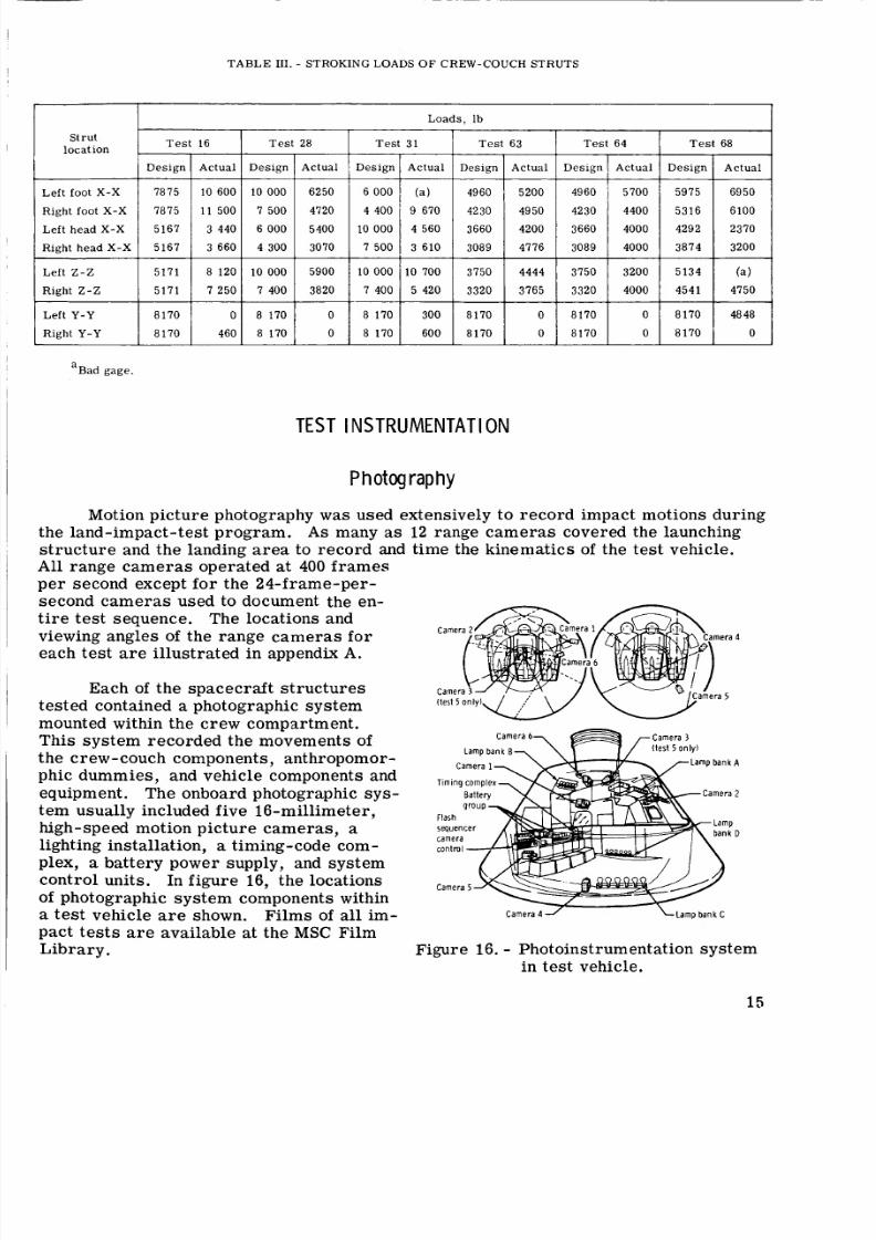
Motion pic tur e photography w a s used extensively to rec ord impact motions duringthe land-impact-test pro gram. A s many as 12 range ca me ra s covered the launching
str uct ure and the landing a re a to reco rd and time the kinematics of the tes t vehicle.ll range cameras operated at 400 fr am eser second except for the 24-frame-per-
second cam er as used to document the en-tire te st sequence. The locations and
viewing angles of the ra nge c am er as foreach test a r e illust rated in appendix A.
Each of the space craf t str uct ure s
tested contained a photographic system
mounted within the crew compartment.This syste m rec orded the movements ofthe crew-couch components, anthropomor-
phic dummies , and vehicle components and
equipment. The onboard photographic s y s -tem usually included five 16-millimeter,high-speed motion picture cameras, alighting installation, a timing-code com-
plex, a battery power supply, and system
cont rol units. In fig ure 16, the locations
of photographic s ys te m components within
a test vehicle are shown.pact tests a r e available at the MSC FilmLibrary.
T,m,ngco
Fil ms of all im-
Figure 16. - Photoinstrumentation syste m
in test vehicle.
15

8/7/2019 Apollo Command Module Land-Impact Tests
http://slidepdf.com/reader/full/apollo-command-module-land-impact-tests 25/61
I nst rumentation
Horizontal-velocity me as uremen ts of the trolley and the tes t vehicle were providedby a timing syste m on the launching str uct ure .broke three carbon electrical conductors mounted on the monorail immediately ahead of
the re lea se point of the tes t vehicle fro m the trolley. The horizontal release velocity at
rel eas e was computed from the ti me s of reco rded voltage dr ops ca used by breaking theconductors and the known spacings between the conductors.
A striker in the trolley sequentially
The leve l of test -vehi cle instr ument ation vari ed fro m nine channels of da ta acqui-sition for the boilerplate te sts to as many as 120 channels fo r the spacecraft tests .Instrumentation of the boilerplate vehicle was limited to range ca me ra s and acc eler om-
eters necessary to determine vehicular kinematics and c. g . accelerations.
tions of specific boile rpla te ins truments are shown in appendix A.The loca-
The spacecraft s tr uc tur es and equipment were instrumented with a much greaternumber and variety of tra nsd uce rs. Thes e included tra nsd uce rs to mea sur e ac cel era -
tions, str ain s, and crew-couch- strut deflections. All tra nsd uce rs (except the self-contained instrumenta tion packages within the c rew dummie s during te st s 16, 28,
and 31) we re connected to test-faci lity reco rding devices by an umbilical cable. Datafro m acce lerometers in the crew dummies during tes ts 63, 64, and 68 also were re-corded through the umbilical cable.
Test-facility recording device s consisted of analog and digital tape r ec or de rs .Acce lerom eter data were rec orded on magnetic tape in analog forma t and la ter wer e
converted to oscillograms at s eve ral frequency filtration levels. Crew-couch-strutloads and deflections also we re reco rded i n analog format and la te r converted to un-filtered oscillograms. Strain measurements were rec orded both in analog and digitalformat. The analog stra in measurements were processed in the sam e manner as thecouch-strut measurements .to produce maximum and minimum normal and sh ea r str es se s. Details of te st instr u-
mentation including locations and ran ges of the var ious tran duce rs are given in appen-dix A of this report.
The digital me asur ement s were proces sed by computer
All inst rumentat ion of the te st facili ty and te st veh icle , including photographicinstrumentation, was centrally timed by an Inter-Range Instrumentation Group B timing
tr ac k to permit correlation of specific impact events on al l transducer recordings.
Accelerations for the fi rs t 15 impact test s with boilerplate tes t vehicles were re -corded by the use of a closed-drum oscillograph data-acquisition s yst em.
of the data re vealed that the a ccel erat ions w ere d istor ted significantly both in magnitudeand in wave form by the galvanomete rs used.
Evaluation
The acceleration data obtained during subsequent boilerplate and spa cecr aft te st swe re recorde d on magnetic tape and then reproduced on oscillograph machines. Thes e
data a re presented as unfiltered, filtered at 320 hertz, and filtered at 100 hertz. Thefilt ering pro ces s di sto rts the data by reducing peak values and by introducing a t ime
lag. All accelerat ion values discu ssed within this repo rt are the authors' interpreta-tion of the values on unfiltered tr ac es . Interpretation was n eces sary to distinguish be-tween primary struc tural accelera tions and those accele rations superimposed b yhigh-frequency, low-energy vibrat ions of s peci fic equipment o r instrumentat ion
mountings.
16
8/7/2019 Apollo Command Module Land-Impact Tests
http://slidepdf.com/reader/full/apollo-command-module-land-impact-tests 26/61
TEST RESULTS
C o m p a r i s o n of the K e n n e d y S pa ce C e n t e r a n d M a n n e d
S p a c e c r a f t C e n t e r Impact Su r face s
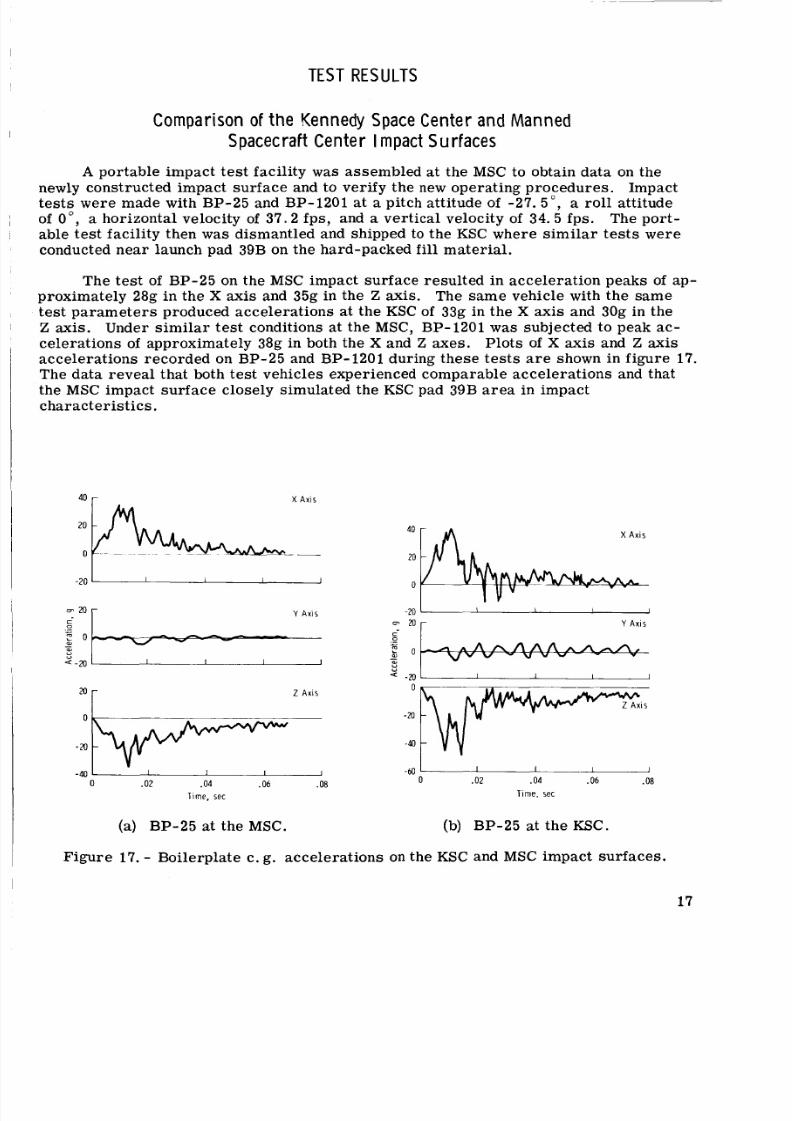
A porta le impact t est facility was assembled at the MSC to obtain Lata on thenewly constructed impac t surface and to verify the new operating pro ced ure s. Impact
tests were made with BP-25 and BP-1201 at a pitch att itude of -27. 5" , a rol l attitude
of O", a horizontal velocity of 37 .2 fps , and a vert ical velocity of 34.5 fps . The port-
able test facility then w a s dismantled and shipped to the KSC where si mi la r te st s were
conducted near launch pad 39B on the hard-packed fill material.
The test of BP-25 on the MSC impact su rfa ce resulted i n acce ler ati on peak s of a p-proximately 28g in the X axis and 35g in the Z axis. The sa me vehicle with the s ame
test pa ra me te rs produced acc ele rat ion s at the KSC of 33g in the X axis and 30g i n the
Z axis. Under sim il ar tes t conditions at the MSC, BP-1201 w a s subjected to peak ac-cel era tions of approximately 38g in both the X and Z axes . Plots of X axis and Z axis
accel erati ons recorded on BP-25 and BP-1201 during thes e test s a r e shown in figur e 17.The data reve al that both te st vehicles experienced compara ble accele ratio ns and that
the MSC impact su rf ac e closely simulated the KSC pad 39B a r ea in impact
characterist ics.
40 r X A x i s
2 A X I S
-40
I I I -
2 0 - Z A X I S
-60
0 .02 .04 .06 .08 0 .02 .04 .06 .08-40
T i m e , s e cl i m e . sec
(a) BP-25 at the MSC. (b) BP-25 at the KSC.
Figure 17. - Boilerplate c. g. acce lerat ions on the KSC and MSC impact surfaces.
17
8/7/2019 Apollo Command Module Land-Impact Tests
http://slidepdf.com/reader/full/apollo-command-module-land-impact-tests 27/61
C o m p a r i s o n of K e n n e d y S p a ce C e n t e rx d X l i
40 T e r r a i n T ype s
20
0
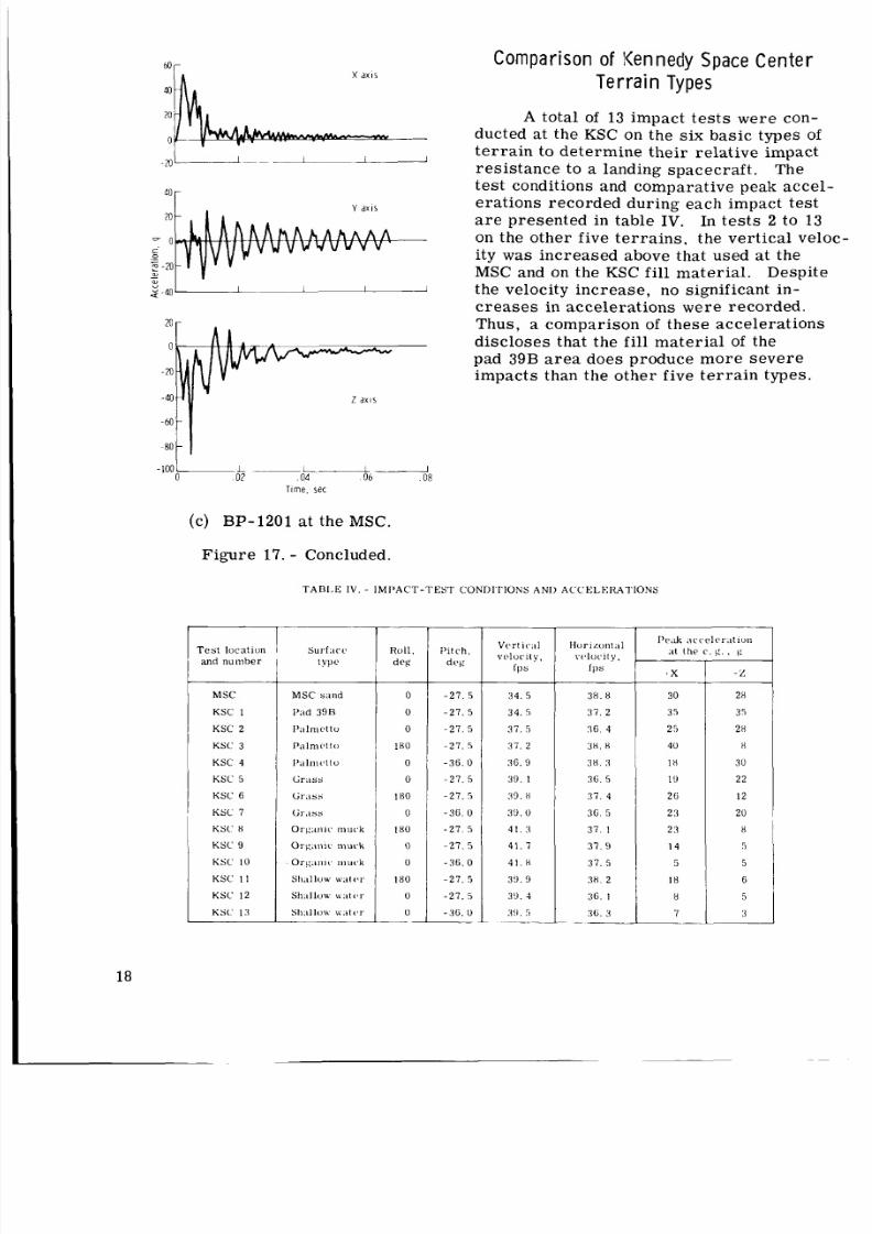
A total of 13 impact te st s we re con-
ducted a t the KSC on the six basic types ofterra in to determine their relat ive impact
resistance to a landing spacecraft. The
tes t conditions and comparativ e peak a ccel -
erations reco rded during each impact testa r e presented in table IV. In te st s 2 to 13
ity was incr ease d above that used at the
s -4 0 the velocity increase, no significant in-
cre ase s in accelerations were recorded.
discloses that the fill material of the
pad 39B ar ea does produce mo re sev ereimpacts than the other five terr ain types.
-2 0
40
20
Y a x i s
- 0 on the other five terra ins , the vertical velocc
y, MSC and on the KSC fill material. Despite20-a,
20 - Thus, a compariso n of the se acceler atio ns
0
-a
- 40
-6 0
80
-
-
- ---Lpi I2 04 06 08
Time, se c
(c) BP-1201 at the MSC
Figure 17. - Concluded.
T A B 1 , E I V . - I M P A C T - T E S T C O N D I T I O N S ANI) A C C E L E R A T I O N S
I Test l o ca t i o n I Surf.icc R o l l . P i t c h ,
I t y p e I d r g 1 dcxgI and
M SC M S C s ; in d 0
K SC 1 I'ad 3 9 B 0
KSC 2 1':i 1m 1 to 0
KSC 3 P.ilmcttu 1 8 0
KSC 4 l ' a l l ~ l l ~ to 0
KSC 5 tiriiss 0
KSC 6 tir.iss i n 0
KSC 7 tir.iss 0
KS( ' ti 0 r g : i i i i c mu c k 18 0
KSC 9 0rg . in ic murk 0
K SC 10 O r g . i ~ i i ( , n u r k 0
K SC 1 1 S l l . I l l O W N':It<'r 18 0
KSC 1 2 sI1:ll luw \ \ : i t < , r 0
KSC 13 sll;lllou \v.ltt'r 0-_ _ -
18
- 2 7 . 5
- 2 7 . 5
- 2 7 . 5
- 2 7 . 5
- 3 6 . 0
- 2 7 . 5
- 2 7 . 5
- 3 6 . 0
- 2 7 . 5
- 2 7 . 5
- 3 6 . 0
- 2 7 . 5
- 2 7 . 5
- 3 6 . 0
V c r I r I I
velocity.I p s
3 4 . 5
3 4 . 5
3 7 . 5
37 . 2
36. 9
3 9 . 1
99 . ti
3 9 . 0
4 1 . 3
4 1 . 7
4 1 . H
3 ! ) .9
3 9 . 4
X I . 5~
3H. ti
3 7 . 2
3 6 . 4
3 8 . n
3t i . :i
3 6 . 5
3 7 . 4
3 6 . 5
3 7 . 1
3 7 . 9
3 7 . 5
3n . 2
3 6 . 1
36 . 3__
1'e.k ; i c c e l t , r . i t i u n
:it th e c . g . , r:
2 6
2 3 2 0
2 3 8
5
5
I 8 6
H 5
7 I~ 3
8/7/2019 Apollo Command Module Land-Impact Tests
http://slidepdf.com/reader/full/apollo-command-module-land-impact-tests 28/61
M a n n e d S p a c e c ra f t C e n t e r T es t P r o g r a m
A total of 47 boilerplate land-impact tests were conducted at the MSC test facility
to obtain inexpensively as much par ametr ic data as possible within a short t ime. Acomplete tabulation of all test conditions is included in appendix B. The boi ler pla te
st ru ct ur es produced ac celerat ion and kinematic data that could be compared with data
obtained with spac ecra ft str uct ure s. This approach w a s an economical means of pr e-dicting reactions of the mor e costly spacecr aft stru ctur es.
A total of five spacecraft vehicles (six tests) w a s impacted to verify the boile r-
plat e resul ts and to est abli sh the land-landing capability of flight-type stru ct ur es . Theimpact te st s with boilerplate and space craft vehicles could be divided into thr ee ba sic
groups: 0" roll landings, 180" roll landings, and skewed landings (whe re the dire ctio n
of t ra ve l does not coincide with the X-Z plane). Pitch attitudes were var ied between
-18" and -36" to simulate a range of possib le impact attitudes resultin g fro m the pa ra -chute rigging tol era nce s and from the swinging motion of a CM descending under a para-
chute cluster. A l l spacecra ft tes ts were conducted at a vert ical velocity of 32 fp s to
simulate the nominal desce nt r ate with thre e deployed parachutes because a two-
parachute recovery terminating in a land landing would be the result of a double systemfailure.
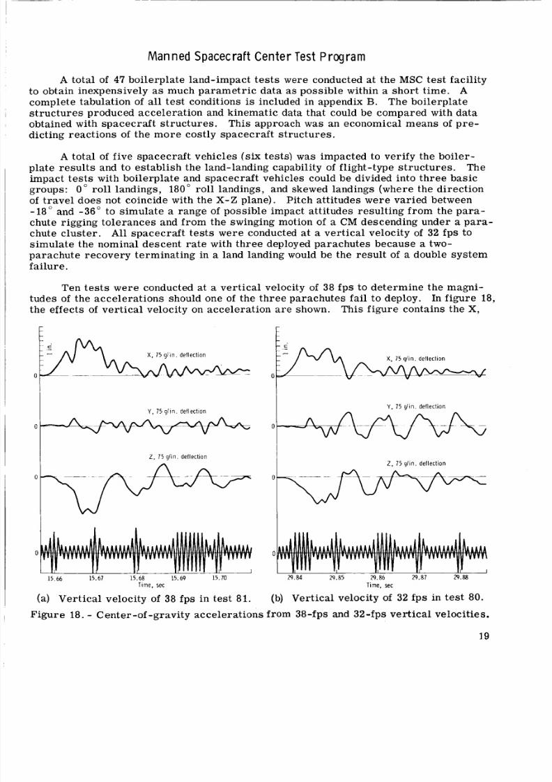
Ten tes ts w ere conducted at a ver tic al velocity of 38 fp s to det ermin e the magni-tudes of t he accele ra tio ns should one of the thr ee parachu tes fail to deploy. In figu re 18,
the effects of ver tic al velocity on acceler ation ar e shown. This figure contains the X ,
t
X , 7 5 g l i n . d e f l e c t io n
0
I Y , 7 5 g l i n . d e f l e c t io n
r
t
I Y , 7 5 g l i n . d e f l e c ti o n
0
I Z, 7 5 g l i n . d e f l e c t i o n
I 2 , 7 5 g l i n . d e f l e c t i o n
0 0
I( , I 1 1 1 I, '
I
15.66 15.67 15.68 15.69 15.70 29.84 29.85 29.86 29.87 29.88
l i m e , s e c
(a) Verti cal velocity of 38 fps in tes t 81.
Time, sec
(b) Vertical velocity of 32 fps in te st 80.
Figure 18. - Center-of -gravity acceler ations f r o m 38-fps and 32-fps ve rt ic al velocities.
19
8/7/2019 Apollo Command Module Land-Impact Tests
http://slidepdf.com/reader/full/apollo-command-module-land-impact-tests 29/61
Y, and Z axis accele rations rec orded during two boilerplate te st s in which the rate of
descent at impact was 38 and 32 fps. Th er e was no horizonta l velocity, and the initial
pitch attitude w a s maintained at -27. 5" during each test . The peak c. g. accelerations
increased from approximately 42g to 52g in the X axis and from 37.5g to 52.5g in theZ axis. The kinetic energy expended during the 32-fps te st was 780 000 foot-pounds com-
pare d with 1 100 000 foot-pounds during the 38-fps test. The difference represents an
incr eas e in energy of 40.8 percent . This significant inc re as e in accele ration and ki-
netic energy is est ima ted to exceed the st ru ct ur al capability of t he command module.
Tes ts a t O o R o l l
Earl ier tes ts with models and full-scale boilerplates indicated that the mo st Se-ve re accel erations during land landings occ urre d when the te st vehicle impacted at a.roll orienta tion of 0 '. Fourtee n boilerpla te and two space cra ft tes ts we re conducted
to define the capabi lity of the CM to withstand the 0" rol l landing.
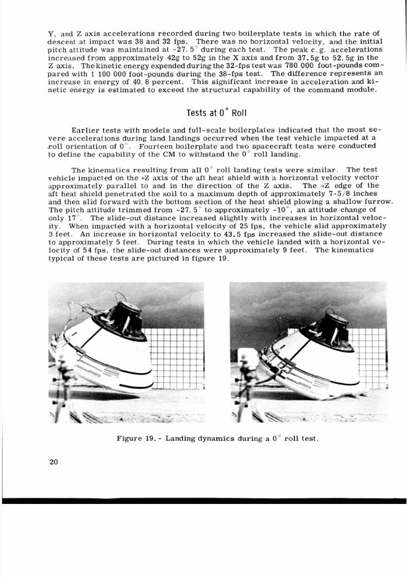
The kinematics resulting from all 0" roll landing tests were s imil ar. The tes t
vehicle impacted on the +Z axis of the aft heat shie ld with a horizontal velocity vect or
approximately para lle l to and in the direction of the Z axis. The +Z edge of theaft heat shield penetrated the soil to a maximum depth of approximately 7-5/8 inc hes
and then sl id forw ard with the bottom sec tion of the heat shield plowing a shallow furrow.
The pitch attitude trim med from -27. 5" to approximately - lo ", an attitude change of
only 17". The slide-out distanc e increa sed slightly with incr ea se s in horizontal veloc-
ity . When impacted with a horizontal velocity of 25 fps, the vehicle sl id approximately
3 feet. An in cre ase in horizontal velocity to 43.5 f ps incre ase d the slide-out di stance
to approximately 5 fee t. During te st s in which the vehicle landed with a horizontal ve-
locity of 54 fps , the slide-out dist ance s we re approximately 9 feet.
typical of these te st s a r e pictured in figure 19.
The kinematics
Figure 19. - Landing dynam ics dur ing a 0 " rol l test .
20
8/7/2019 Apollo Command Module Land-Impact Tests
http://slidepdf.com/reader/full/apollo-command-module-land-impact-tests 30/61
- -
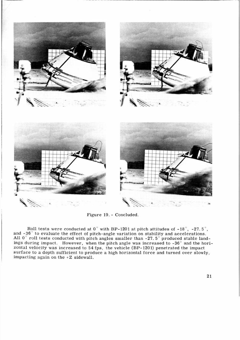
Figure 19. - Concluded.
Roll te st s wer e conducted a t 0" with BP-1201 at pitch atti tude s of -18", -27. 5 " ,and - 3 6 " to evaluate the effect of pitch-angle variation on stab ilit y and accel era tio ns .
Al l 0 " ro ll t es ts conducted with pitch angles sma ller than -27. 5" produced stab le land-
ings dur ing impact. However, when the pitch angle was incr ease d t o -36" and the ho ri-
zontal velocity was inc reas ed to 54 fps , the vehicle (B P- 1201) penetra ted t he impact
sur face to a depth sufficient to produce a high horizontal force and turned over slowly,impactin.g aga in on the +Z sidewall.
2 1
8/7/2019 Apollo Command Module Land-Impact Tests
http://slidepdf.com/reader/full/apollo-command-module-land-impact-tests 31/61
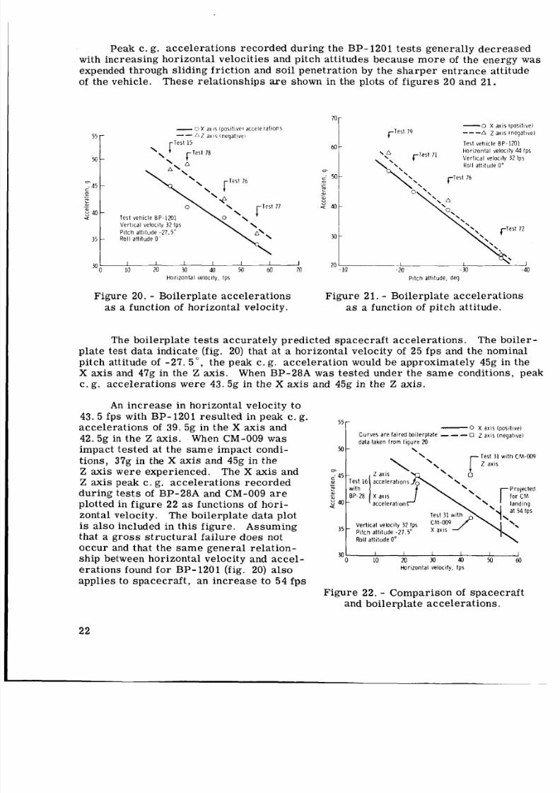
Peak c. g. acce lerat ions record ed during the BP- 1201 tests generally decreased
with incre asing horizontal velocitie s and pitch attitudes because m or e of the energy was
expended through sliding friction and s oil penetration by the sh ar pe r entrance attitude
of the vehicle. These relationships are shown in the plot s of f ig ur es 20 and 21.
55-
50 -
m
. 4 5 -
0-e
9 0
aJ--
U
35 -
- O X a x i s ( p o s i t i v e 1 a c c e l e r a t i o n sA Z a x i s l n e q a t i v e i-
r T e s t 1 5
T e s t v e h i c le B P - 1 2 0 1
V e r t i c a l v e lo c i ty 3 2 I p s
P i t c h a t t i t u d e - 2 7 .5 "
R o l l a t t i t u d e 0
I I I I I I I
10 M 30 40 5 0 60 70
H o r i z o n t a l v e lo c i ty . I p s
Figure 20. - Boilerplate accelerations
as a function of horizontal velocity.
-0X a x i s tp o s i t i v e l79 - - -6 Z a x i s l n e g a t i v e l
T e s t v e h i c l e B P - 1 2 0 1
H o r i z o n t a l v e l o c it y 44 fp s\ A +-lest 71 V e r t i c a l v e l o c it y 3 2 I p s+\\ Roll a t t i t u d e 0'
\ \ \ +-Test 76
o \\.-Test 72
- 1 I
- 20 -30 - 40
P i t c h a t t i tu d e . d e g
Figure 21. - Boilerplate accelerations
as a function of pitch attitude.
The boilerplate t est s accurately predicted spac ecraft accelerations. The boiler-
plate test da ta indicate (fig. 20) that at a horizontal velocity of 25 fps and the nominal
pitch attitude of -27. 5", the peak c. g. acc ele rat ion would be approxi mately 45g in theX axis and 47g in the Z ax is . When BP-28A w a s tested under the s am e conditions, peak
c. g. acce lera tions were 43. 5g in the X axis and 45g in the Z axis.
An in cr ea se in horizontal velocity to
43. 5 fps with BP-1201 result ed in peak c. g.
accelerations of 39. 5g in the X axis and
42.5g in the Z axis. When CM-009 wasimpact tested at the sa me impact condi-
tions, 37g in the X axis and 45g in theZ axis were experienced.
Z axis peak c. g. accelerations recorded
during te st s of BP-28A and CM-009 a r eplotted in figu re 22 as func tions of hori -
zontal velocity. The boile rplat e dat a plotis al so included in thi s figur e. Assumingthat a gross struc tural failu re does not
occu r and that the sa me gener al relation-
ship between horizontal velocity and acce l-
erations found for BP-1201 (fig. 20) also
applies to spacecraft, an incre ase to 54 fps
The X axis and
55--0 X a x i s I p o s i t i v e l
C u r v e s a r e f a i r e d b o i le r p l a t e - - - 0 Z a x i s t n e g a t i v e l
d a t a t a k e n f r o m f i g u r e 20
M - \
Test 31 with CM-009
Z a x i s
\
4 a c c e l e r a t i o n
\i t c h a t t i t u d e -2 7 5"
Roll a t t i t u d e 0"
30 I I I I I I0 10 20 3 0 4 0 M 60
Hor i z on t a l Ve l OC i t y . fp s
Figu re 22. - Compari son of spa cec raf t
and boilerplate acceleratio ns.
22
8/7/2019 Apollo Command Module Land-Impact Tests
http://slidepdf.com/reader/full/apollo-command-module-land-impact-tests 32/61
in the horizon tal landing velocity of a spacecraf t would r esu lt in X axi s and Z axis peak
c. g. a cce ler ati ons of 30g and 38g, respect ively. This extrapolation is shown infigu re 22.
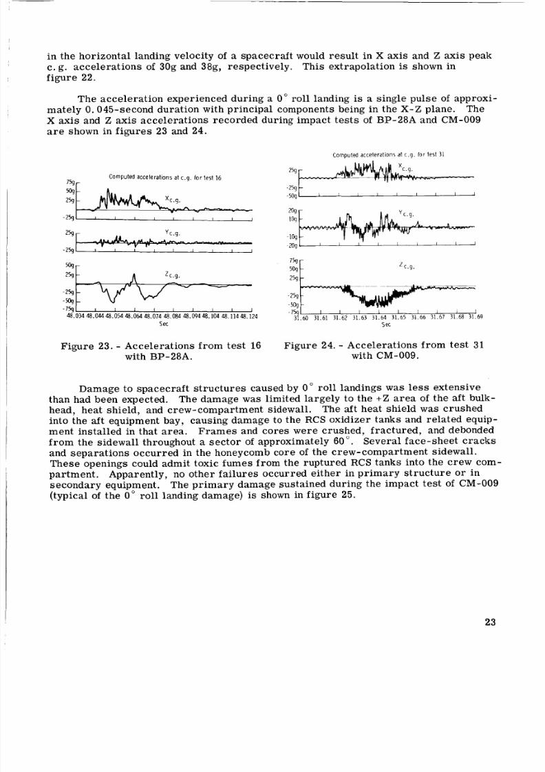
The acceleration experienced during a 0" roll landing is a single pul se of approxi-mate ly 0.045-second duration with principal components being in the X-Z plane.
X axis and Z axis accel erati ons recorded during impact tes ts of BP-28A and CM-009
are shown in figures 23 and 24.
The
C o m p u t e d a c c e l e r a t i o n s a t c . 9 . fo r tes t 31
C o m p u t e d a c c e l e r a t i o n s a t c . g. fo r t es t 16
7% r
% -
2% -
-- ---2 5 9 1 I I I I I I I I
259
. .-259 I I I I I I I I I I
z c . g .
- 259
-%75 9
48 . 034 48.044 48 . 054 48.064 8 . 074 48 . 084 48 . 094 48 . 104 48 . 1 14 48 . 124
S c
Figure 23. - Accelerations from te st 16with BP-28A.
259
- 2 5 9 t 1 , , I I I I I
- 509
I I I I I 1 I I I
ZC. 9 .
-7Gl I I I 1 I I 1 1 I
31 . 60 31 . 61 31 . 62 31 . 63 31 . 64 31 . 65 31 . 66 31 . 67 31 . 68 31 . 69
Se c
Figure 24. - Accelerations from tes t 31with CM-009.
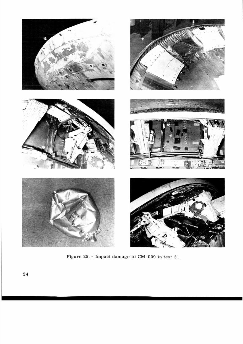
Damage to spacecraft structures caused by 0" roll landings was le ss extensive
The aft heat shield was crushedthan had been expected. The damage w a s limited largely to the + Z area of the aft bulk-
head, heat shield, and crew-compartment sidewall.
into the aft equipment bay, causing damage to the RCS oxidizer tanks and related equip-
ment installed in that ar ea . Fr am es and cores were crushed, fractu red, and debonded
fr om the sidewall throughout a se ct or of approximately 60". Several face-sheet crack s
and sep ara tio ns occu rred in the honeycomb core of the crew-compartment sidewall.Thes e openings could admit toxic fum es fro m the ruptured RCS anks into the crew com-
partment. Apparently, no other failur es occurred either in pri mar y struct ure or insecondary equipment. The pri mar y damage sustained during the impact tes t of CM-009
(typical of the 0" rol l landing damage) is shown in figure 25.
23
8/7/2019 Apollo Command Module Land-Impact Tests
http://slidepdf.com/reader/full/apollo-command-module-land-impact-tests 33/61
Figure 25 . - Impact damage to C M-0 0 9 i n test 31.
2 4
8/7/2019 Apollo Command Module Land-Impact Tests
http://slidepdf.com/reader/full/apollo-command-module-land-impact-tests 34/61
Tests a t 180° Roll
Thirteen tests with BP-1201 and spacecraft te s ts with CM-008, CM-009, and
CM-011 were conducted to define the capability of the Apollo CM to withstand 180" rol l
landings. Unlike the 0" roll tests, all landings at a ro ll of 180" were unstable, even atrelati vely low horizontal velocitie s (25 fps). As the horizontal velocity was i ncreas ed,the tumbling of the te st vehicle became more violent because of t he sphe rical shape of
the heat shield and the direct ion of the for ces involved.
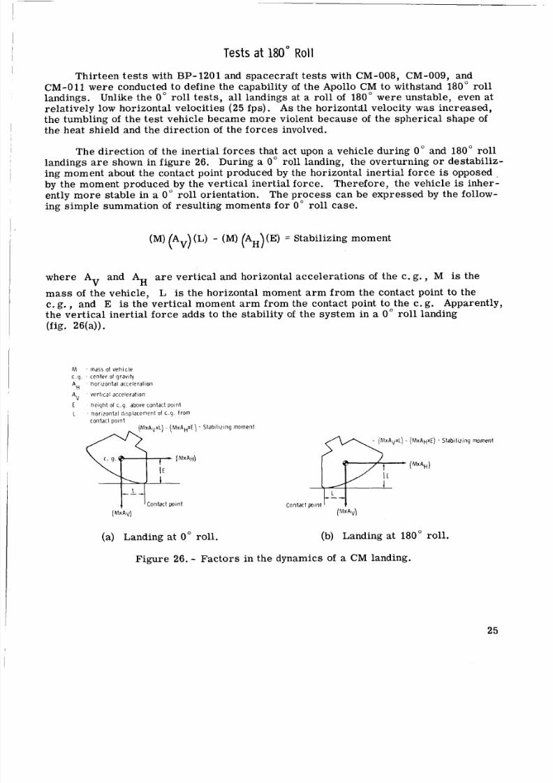
The direction of the i ner tia l fo rces that act upon a vehicle during 0" and 180" roll
landings a r e shown in figure 26. During a 0" roll landing, the overturning or destabiliz-
ing moment about the contact point produced by the horizontal ine rtia l forc e is opposed
by the moment produced by the vert ica l iner tia l force . Therefore, the vehicle is inher-ently mor e sta ble in a 0" roll orientation. The proces s can be expres sed by the follow-
ing simpl e summation of result ing moments for 0" roll case.
(M) (Av) (L) - (M ) (AH)(E) = Stabilizing moment
where A and AH a r e ver tica l and horizontal accele rat ions of the c. g. , M is theV
m as s of the vehicle, L is the horizontal moment a r m fro m the contact point to the
c. g., and E is the verti cal moment ar m from the contact point to the c. g. Apparently,the vertical inertial forc e adds to the stability of the system in a 0" roll landing
(fig. 26(a)).
M m a s s of v e h i c l e
c q c e n t e r o f g r a v i t y
AH h o r i z o n t a l a c c e le r a t io n
A V v e r t i c a l a c c e l e r a t i o n
E h e i g h t 01 c q a b o ve c o n t a c t p o i n t
t h o r i z o n t a l d i s p l a ce m e n t of c g l r o m
c o n t a c t pointA v x L ) ( M x A H ~ E )
c o n t a c t point( M X A ~ X L )M X A ~ X E )y7-MxAHj
C o n l a c t p o i n t
S t a b i l i z i n g m o m e n t
S t a b i l iz i n g m o m e n t
(a) Landing at 0" rol l. (b) Landing at 180" roll.
Figure 26. - Fac tors in the dynamics of a CM landing.
25
8/7/2019 Apollo Command Module Land-Impact Tests
http://slidepdf.com/reader/full/apollo-command-module-land-impact-tests 35/61
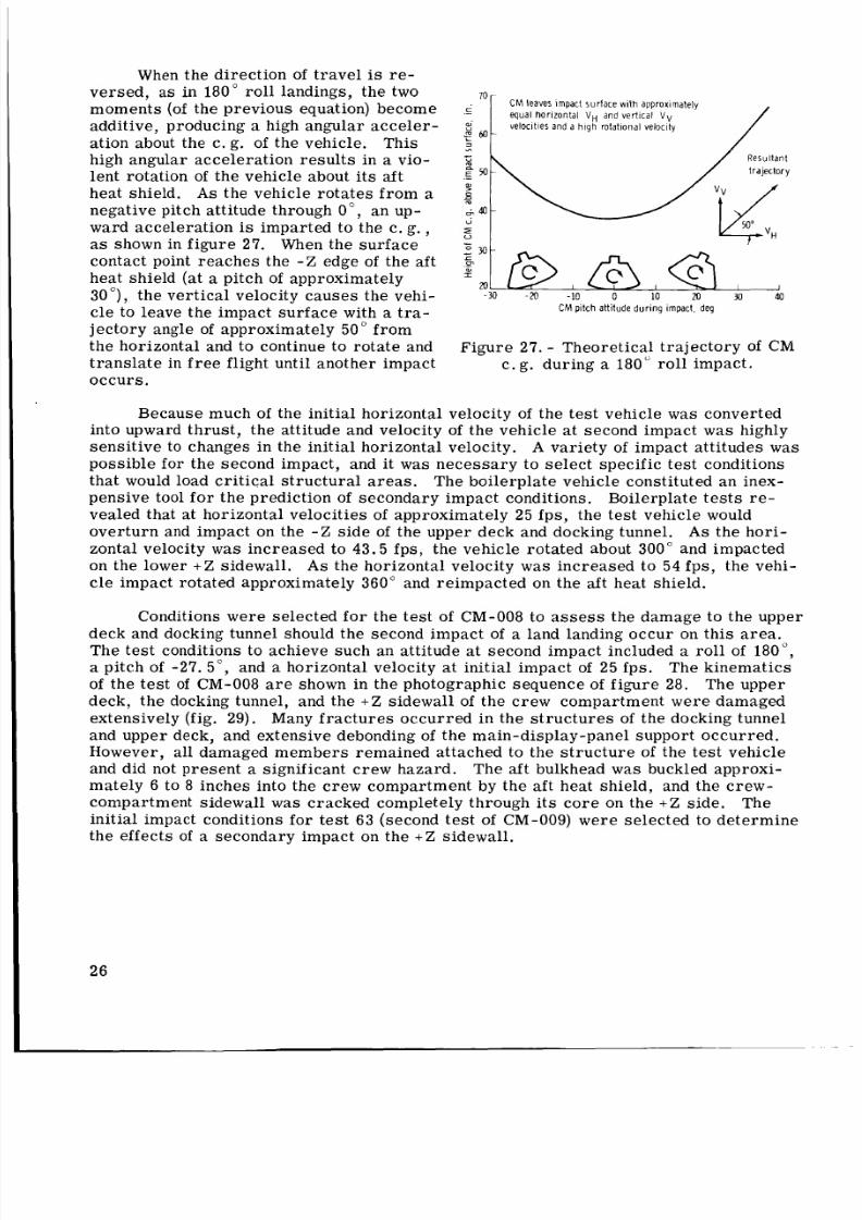
When the direct ion of t ra ve l is re-ver sed , as in 180" roll landings, the two
moments (of the pr eviou s equation) become
additive, producing a high angular acc ele r-
ation about the c. g. of the vehicle. Thishigh angular acceleration re sul ts in a vio-
lent rotat ion of the vehicle about it s aft
heat shield. A s the vehicle rotates fr om anegative pitch attitude through 0", an up-
ward acceleration is imparted to the c. g.,
as shown in figu re 27. When the sur face
contact point r eac hes the - Z edge of the af t
heat shield (at a pitch of approxima tely
30 ), the verti cal velocity c auses the vehi-
cle to leave the impa ct s urfac e with a t r a -
j ect ory angle of approxima tely 50" from
the ho rizontal and to continue to rotat e and
tra nsl ate in fre e flight until another impact
occurs.
70C M e a v e s i m p a c t s u r f a c e w i t h a p p r o x i m a t e l y
equal h o r i z o n t a l VH a n d v e r l i c a l V V
v e l o c i t i e s a n d a h i g h r o t a t i o n a l v e l o c l t y
._d
2 ) -2
- I
cFI
2 M -
20 I I 1 I
-30 -20 -10 0 10 20 M 40
CM p i t c h a t t it u d e d u r i n g i m p a c t, d e g
Figu re 27. - Theo retical tra jec tory of CMc. g. during a 180" roll i mpact.
Because much of t he initial horizonta l velocity of the te st veh icle was converted
into upward thru st, the attitude and velocity of the vehicle a t second impact was highly
sen sit ive to changes in the initial horizontal velocity. A vari ety of impact attitudes was
possible for the second impact, and it was ne ces sar y to select specific tes t conditions
that would load criti cal str uct ura l area s. The boilerplate vehicle constituted an inex-
pensive tool fo r the prediction of secondary impact conditions.
vealed that at horizontal veloc ities of approxima tely 25 fps, the tes t vehicle would
ove rtu rn and impact on the - Z side of the upper deck and docking tunnel. As the hori-
zontal velocity w a s increased to 43.5 fps, the vehicle rotated about 300" and impacted
on the lower + Z sidewall. A s the horizontal velocity w a s increased to 54 ps, the vehi-
cle impact rotated approximately 360" and reimpacted on the aft heat shield.
Boilerplate te st s re-
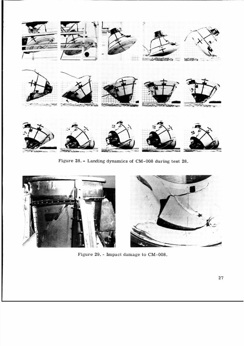
Conditions wer e selecte d for the tes t of CM-008 to a ss es s the damage to the upper
deck and docking tunnel should the second impac t of a land landing occur on this area.The tes t conditions to achieve such an attitude at second impact included a ro ll of 180",a pitch of -27. 5", and a horizontal velocity a t initial impact of 25 fps. The kinemati cs
of th e test of CM-008 are shown in the photographic seque nce of figu re 28. The upper
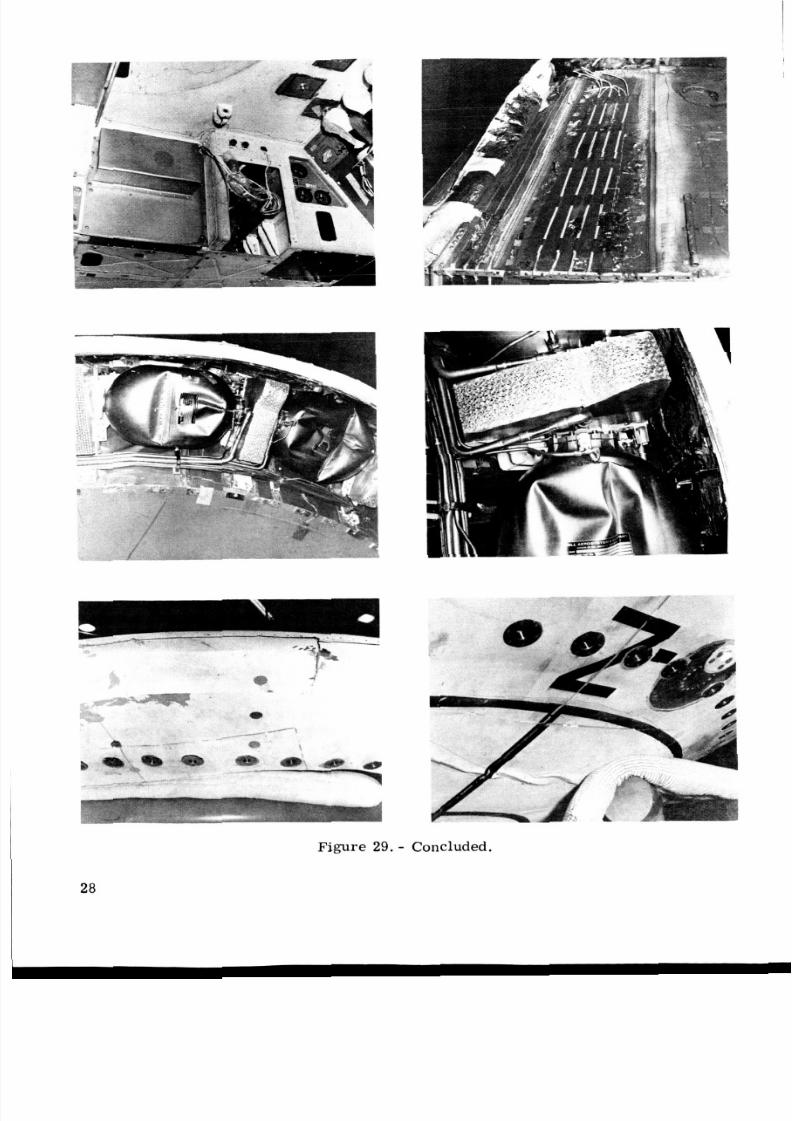
deck, the docking tunnel, and the + Z sidewall of the cr ew comp artment were damaged
extensively (fig. 29). Many fr ac tu re s occu rred in the stru ct ur es of the docking tunnel
and uppe r deck, and extensive debonding of th e main-display-pane l support occu rred.However, all damaged mem ber s remained attached to the str uc tu re of the test vehicle
and did not present a significant c rew h azard. The aft bulkhead was buckled approxi-
mately 6 to 8 inches into the cre w compartm ent by the aft heat shield, and the cre w-
compartment sidewall w a s cracked completely through its co re on the + Z side. The
initial impact conditions for test 63 (second test of CM-009) w ere selec ted to det erm inethe effec ts of a secondary im pact on the + Z sidewall.
26
8/7/2019 Apollo Command Module Land-Impact Tests
http://slidepdf.com/reader/full/apollo-command-module-land-impact-tests 36/61
. . __ . - . .
. .
. .
. .
Figure 28. - Landing dynam ics of CM-008 du ring test 28.
Figure 29. - Impact damage to CM-008.
27
8/7/2019 Apollo Command Module Land-Impact Tests
http://slidepdf.com/reader/full/apollo-command-module-land-impact-tests 37/61
Figure 29. - Concluded.
28
8/7/2019 Apollo Command Module Land-Impact Tests
http://slidepdf.com/reader/full/apollo-command-module-land-impact-tests 38/61
8/7/2019 Apollo Command Module Land-Impact Tests
http://slidepdf.com/reader/full/apollo-command-module-land-impact-tests 39/61
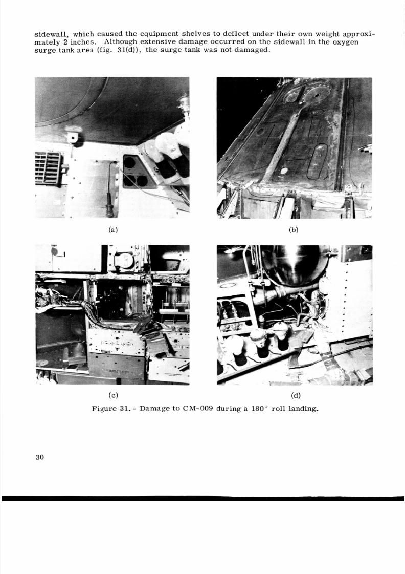
sidewall, which caused the equipment shelves to deflect under their own weight approxi-
mately 2 inches. Although extensive damage occur red on the sidewall in the oxygen
surge tank ar ea (fig. 3l(d )), the sur ge tank was not damaged.
( c ) (4Figure 31. - Damage to C M- 0 0 9 during a 180" roll landing.
30
8/7/2019 Apollo Command Module Land-Impact Tests
http://slidepdf.com/reader/full/apollo-command-module-land-impact-tests 40/61
...d
..-
I
Figure 31. - Concluded.
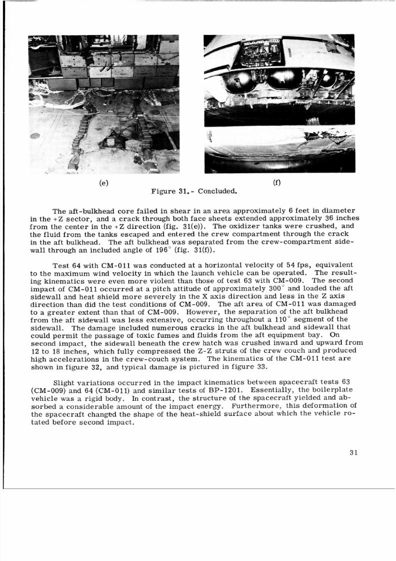
The aft-bulkhead co re failed in shear in an ar ea approximately 6 feet in diam eterin the +Z sector, and a cra ck through both face shee ts extended approximately 36 inches
from the center in the +Z direction (fig. 31(e)). The oxidizer tanks were crushed, and
the fluid from the tanks escaped and entered the crew compartment through the cra ck
in the aft bulkhead. The aft bulkhead w a s separated from the crew-compartment side-
wall through an included ang le of 196" (fig. 3l(f)).
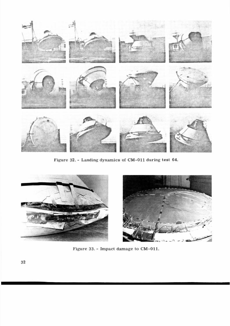
Te st 64 with CM-011 was conducted at a horizontal velocity of 54 ps, equivalent
to the maximum wind velocity in which the launch vehicle ca n be operated . The res ult-ing kinema tics w ere even mo re violent than those of te st 63 with CM-009. The secondimpact of CM-011 occurr ed at a pitch att itude of approximately 300" and loaded the aft
sidewall and heat shield mo re severely in the X axis direction and less in the Z axis
di rec tio n than did the tes t conditions of CM-009.
to a gre a te r extent than that of CM-009. However, t he sep ara tion of the aft bulkhead
from the aft sidewall was less extensive, occu rring throughout a 110" segm ent of t he
sidewall.
could pe rm it the passa ge of toxic fumes and fluids fr om the aft equipment bay. On
second impact, the sidewall beneath the crew hatch w a s crushed inward and upward from
1 2 to 18 inches, which fully compressed the Z - Z st ru ts of the crew couch and produced
high acceler ation s in the crew-couch syst em. The kinematic s of the CM-011 test a r e
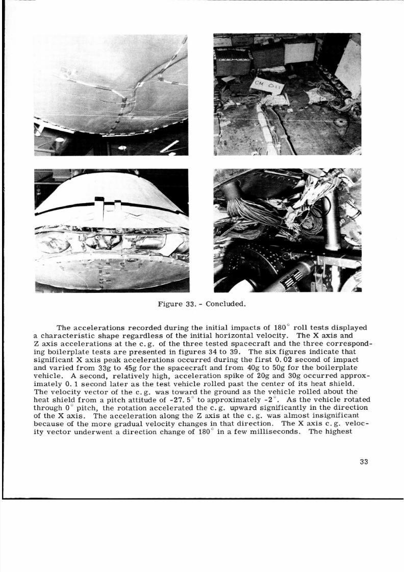
shown in fig ure 32, and typical damage is pictured in figure 33.
The aft ar ea of CM-011 w a s damaged
The damage included numerous crac ks in the aft bulkhead and sidewall that
Slight variations occu rred in the impact kinemati cs between spacec raft te st s 63(CM-009) and 64 (CM-011) and si mi la r te st s of BP-1201. Essentially , t he boile rp lat e
vehicle was a rigid body. In cont rast , the struc tur e of the spacec raft yielded and ab-
sorbed a consider able amount of the impact energy. Furt herm ore, this deformation of
the spacecraft changed the shape of the heat-shield surface about which the vehicle ro-tated before second impact.
31
8/7/2019 Apollo Command Module Land-Impact Tests
http://slidepdf.com/reader/full/apollo-command-module-land-impact-tests 41/61
1c - a
If' e
iI
t
I
Figure 32. - Landing dynamics of CM-011 uring test 64.
Figure 33 . - Impact damage to CM-011.
32
8/7/2019 Apollo Command Module Land-Impact Tests
http://slidepdf.com/reader/full/apollo-command-module-land-impact-tests 42/61
Figure 33. - Concluded.
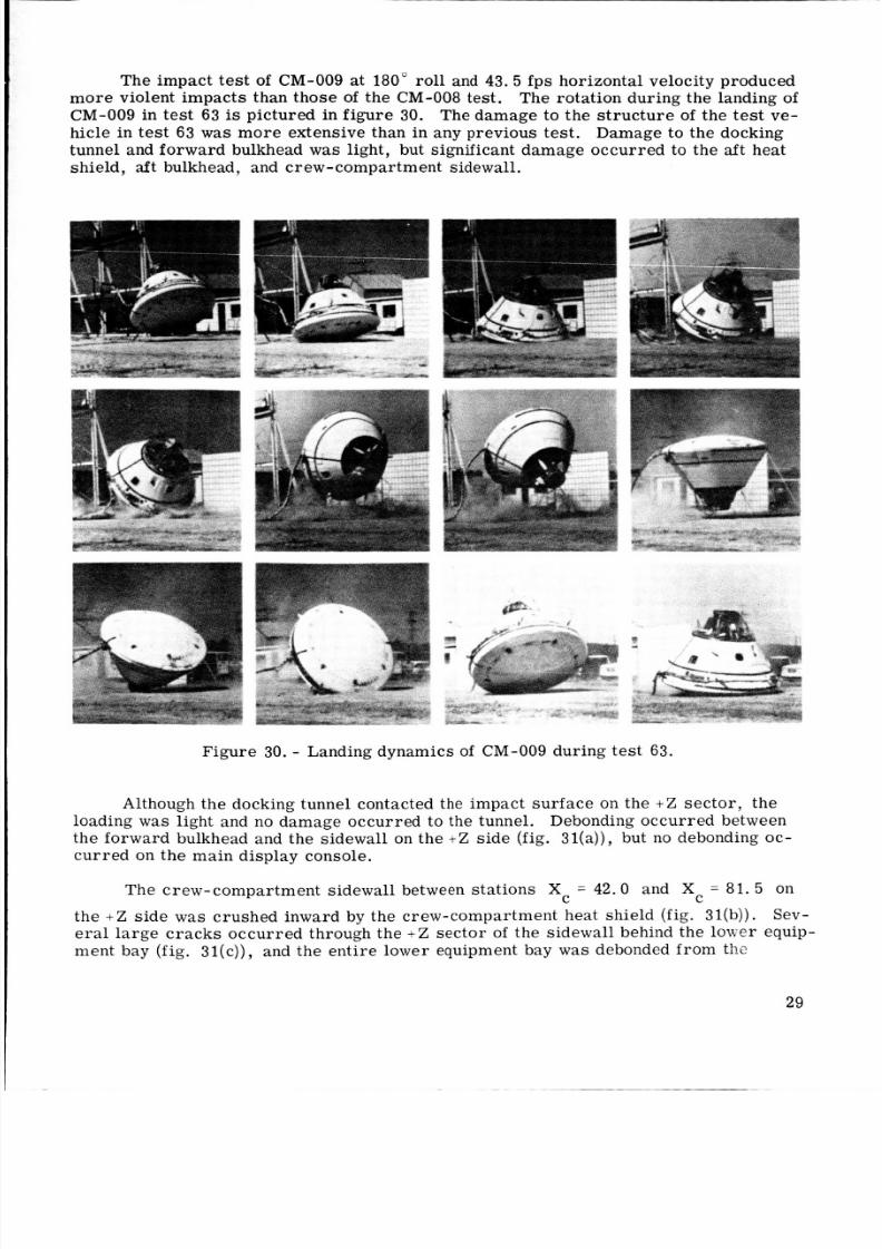
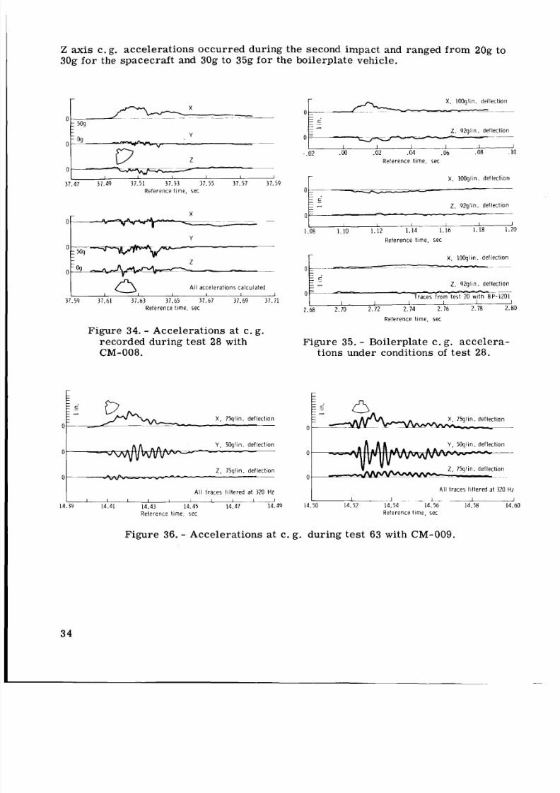
The acce lera tions recorded during the initial impa cts of 180 rol l te st s displayed
a cha rac ter ist ic shape reg ard les s of the initial horizontal velocity. The X axis and
Z axis acce lera tions at the c.g. of the thr ee tested spacecraft and the th re e correspond-
ing boilerplate te st s are pres ented in fig ure s 34 to 39. The six figures indicate thatsignificant X axis peak accelerations occurred during the first 0.02 second of impact
and varied fro m 33g to 45g for the spacecra ft and from 40g to 50g fo r the boi lerplatevehicle. A second, relatively high, acceleration spike of 20g and 30g occ urr ed approx-
imately 0. 1 second late r as the te st vehicle rolled past the cente r of it s heat shield.
The velocity vec tor of the c. g. w a s toward the ground as the vehicle rolled about theheat shield from a pitch a ttitude of - 27 . 5" to approximately -2". A s the vehicle rotated
through 0" pitch, the rotation acce lera ted the c. g. upward significantly in the direct ionof the X axis. The acc eleration along the Z axis at the c. g. was alm ost insignificantbecause of the mo re gradual velocity changes in that direction. The X axis c. g. veloc-
ity vec tor underwent a direction change of 180" in a few milliseconds. The highest
33
8/7/2019 Apollo Command Module Land-Impact Tests
http://slidepdf.com/reader/full/apollo-command-module-land-impact-tests 43/61
Z axis c.g. acceleratio ns occur red during the second impact and ranged from 20g to
30g fo r t h e spac ecra ft and 30g to 35g fo r the boilerpla te vehicle.
37.47 37.49 37.51 37.53 37.55 37.57 37.59
R e f e r e n c e t im e . s ec
A ll a c c e l e r a t i o n s c a l c u l a t e d,I I I 1
37.59 37.61 37.63 37.65 37.67 37.69 37.71
R e f e r e n c e t i m e . s e c
Figure 34. - Accelerations at c. g .
recorded during tes t 28 with
CM-008.
X . 1 0 C q f i n . d e f l e c t i o n
-~
Z. 9 2 g l i n . d e f l e c t i o n
0
I I I I I I
- .0 2 .MJ .02 . 04 . 06 . 08 . 10
R e f e r e n c e t im e . s ec
x. 1 i N q l i n . d e f l e c t i o n
I 2 . 9 2 g f i n . d e f l e c t i o n
1 . 08 1 . 10 1 . 12
R e f e r e n c e t im e . s ec
x. 1 0 0 g l i n . d e f l e c t i o n
Z. 9 2 g l i n . d e f l e c t i o n
2.68 2 . 70 2 . 72
R e f e r e n c e time. sec
Figure 35. - Boilerplate c. g. accelera-
tio ns under condi tions of te st 28.
X. 75qlin. d e f l e c t i o n
0
0 0
0 0
A l l t r ac es f i l t e r ed a1 320 H r
I I I I I 1 1 1 I i - ~ ~ 1~ -. l . ._ -4.39 14.41 14.43 14.45 14.47 14.4 9 14.50 14.52 14.54 14.56 14.58 14 . 60
R e f e r e n c e l i m e , s ec
A l l t r a c e s f i l t e r e d a t 3 2 0 Hz
R e f e r e n c e l ime. se c
Figure 36. - Accelerations at c. g . during test 63 w i t h CM-009.
34
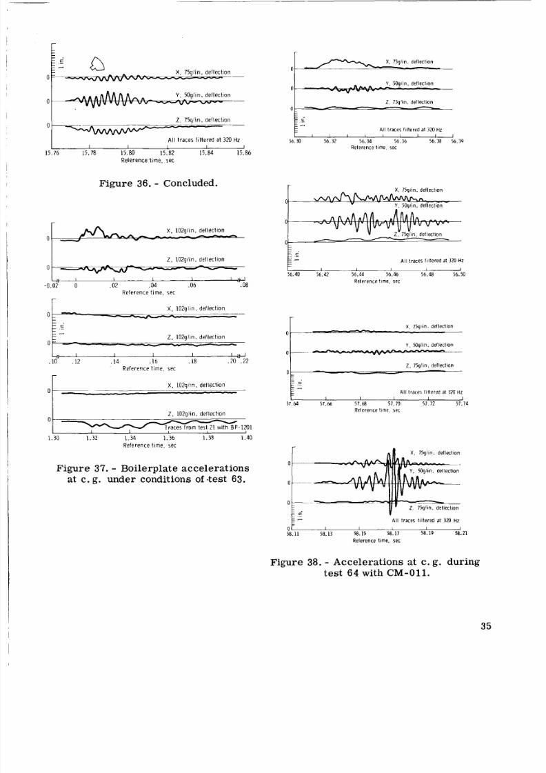
8/7/2019 Apollo Command Module Land-Impact Tests
http://slidepdf.com/reader/full/apollo-command-module-land-impact-tests 44/61
c
0
2 . 7 5 g i i n . d e f l e c t i o n
A l l t r a c e s f i l t e r e d a t 32 0 Hz
011 1 I I
15 . 76 15.78 15.80 15 . 82 15 . 84 15 . 86
R e f e r e n c e t i m e , sec
Z. 0 2 g f i n . d e f l e c t i o n
- -
Figure 36. - Concluded.
0 -
0 -
X. 1 0 2 g f i n . d e f l e c t i o n
r
X . 1 0 2 g l i n . d e f l e c t i o n-p_ .-
1 5-_ -- 2 . 1 0 2 g f i n . d e f l e c t i o n--
I I I I i I 4
0 .
0 -
Figure 37. - Boilerplate accelerations
at c. g. unde r conditions of -test 63.
-x . 7%1in.def lec t ion
Y . 50gfin. def lect ion
0---P. 75qIin. deflect ion
-_ .
- c
- -
X. 75gi in. def lect ion
0
0
2 . 75g' in. def lect ion
A l l t races f i l tered at 320 H
56.30 56.3 2 56.34 56.36 56.38 56.39Reference t ime. sec
X. 75gi in. def lec t ion
Y . 5Cqlin. def lect iond w n k h . -
c-- A l l t races f i l tered at 320 HZ
56.40 56.42 56.44 56.46 56.48 56.50I I I -
Reference t ime. sec
A l l t races f i l tered at 320 H
58.11 58.13 58.15 58.17 58.19 58.21
Reference time. set
Figure 38. - Accelerations at c. g. during
test 6 4 with CM-011.
35
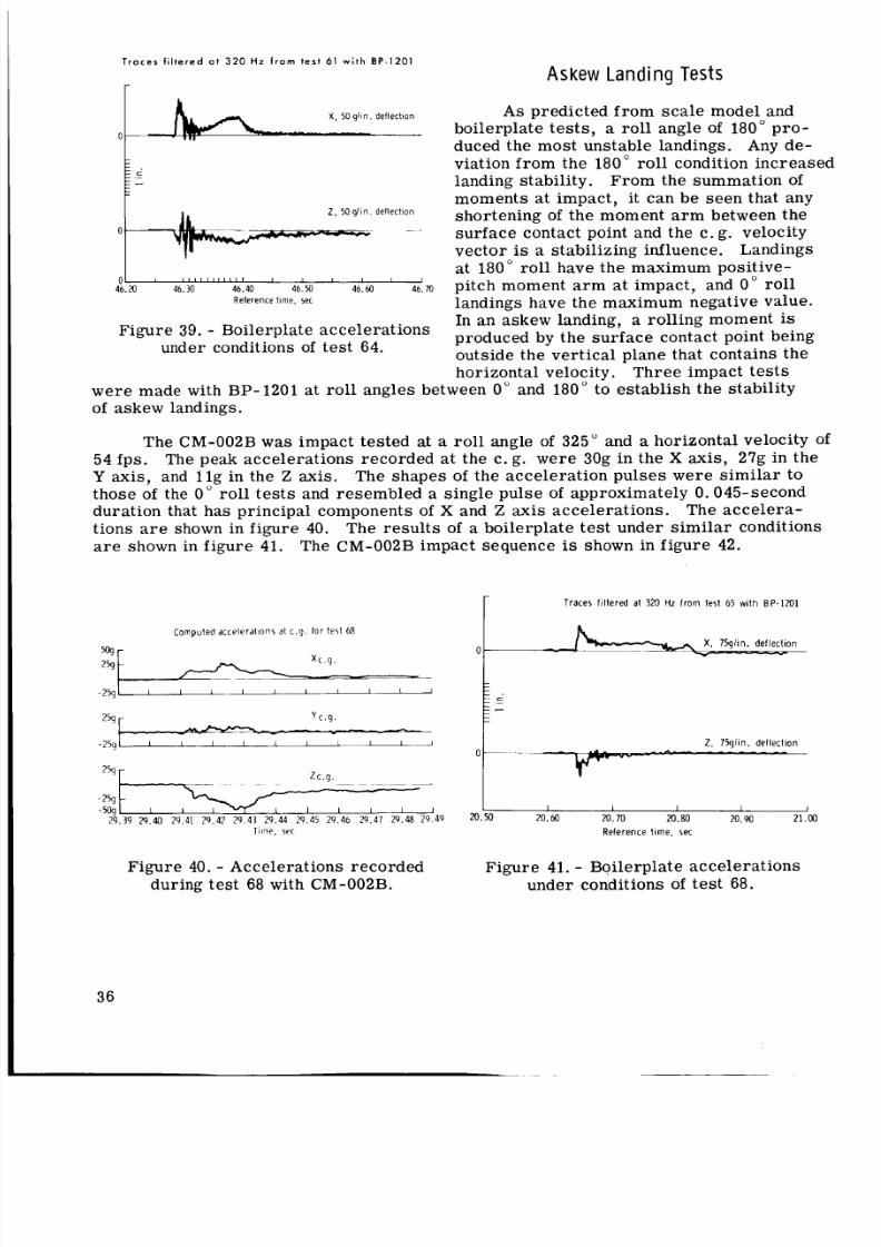
8/7/2019 Apollo Command Module Land-Impact Tests
http://slidepdf.com/reader/full/apollo-command-module-land-impact-tests 45/61
T r a c e s f i l t e r e d a t 3 2 0 Hz f r o m t e s t 61 w i t h B P - 1 2 0 1
0
0 .
-
X , 50 g!tn. deflection
-c-
Z, 0g i in deflection
~
01 , I I 1 I I I I I I 1 I I I I I I I
46 .20 46 .30 46 .40 46 .50 46 .60 46 . 70
Relerence time. sec
0 -
Figure 39. - Boilerplate accelera tions
under conditions of tes t 64.
X. 75glin. deflection-
As k e w Landing Tes ts
As predicted from scale model andboilerplate tes ts, a roll angle of 180" pro -
duced the mos t unstable landings. Any de-viation from the 180" roll condition increased
landing stability. From the summation of
moments at impact, it can be seen that anyshortening of the moment a r m between thesur fac e contact point and the c.g . velocityvector is a stab iliz ing influence. Landings
at 180" roll have the maximum positive-pitch moment a r m at impact, and 0" roll
landings have the maximum negative value.In an askew landing, a rolling moment is
produced by the su rf ac e contact point beingoutside the vert ical plane that contains thehorizontal velocity. Three impact te st s
we re made with BP-1201 at rol l angles between 0" and 180" to est abli sh the stability
of askew landings.
The CM-OO2B w a s impact tested at a rol l angle of 325" and a horizontal velocity Of
The peak accelerat ions re corde d a t the c. g. wer e 30g in the X axis, 27g in the4 fps.Y axis, and l l g in the Z axis. The shapes of the acceleration pulses were sim ila r to
those of the 0" rol l tes ts and rese mbled a single pulse of approximately 0.045-secondduration that has principal components of X and Z axis accelerations . The accelera-tions a r e shown in figure 40.
a r e shown in figure 41.
The resu lt s of a boilerplate test under similar conditions
The CM-OOBB impact sequence is shown in figure 42.
Traces filtered at 320 Hz from lest 65 with BP-1 2 0 1
rComputed a c c e l e r a t l o n s a t c . 9 . for test 68
259
-2 5 9 1 I I I I I I I I I I
2% y c . 9 .
-259 I I I I 1 1 I I 1 I
-
z c . 459 r
~
a
- 259
- 509 I I I I I I 12 9 . 3 9 29.40 29 41 29.42 29 4 3 29 44 29 45 29 4 6 29 4 1 29.48 29 49
Ti i l ie , sec
Figure 40. - Accelerations recorded
during test 68 with CM-002B.
Z. 75glin. deflection
20.
1 J " L - -20.60 20.70elerence t ime 0.80ec 20.90 21.00
Figure 41. - Boilerplate accelera tions
under conditions of te st 68.
36
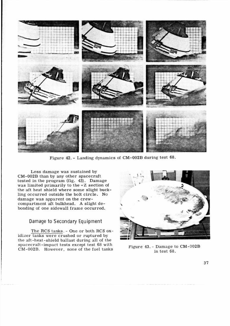
8/7/2019 Apollo Command Module Land-Impact Tests
http://slidepdf.com/reader/full/apollo-command-module-land-impact-tests 46/61
Figure 42. - Landing dynamics of CM-OO2B during test 68.
Les s damage w a s sustained by
CM-OO2B than by any othe r spacecraf ttested in the progra m (fig. 43). Damage
w a s limited primari ly to the +Z section ofthe aft heat shield where some slight buck-ling occurre d outside the bolt c irc le . N o
damage w a s apparent on the crew-compartment aft bulkhead. A slight de-
bonding of one sidewall fr am e occurre d.
D am age t o S ec onda r y E qu i pm e n t
The RCS tank s. - One o r both RCS ox
idizer tanks were crushed or ruptured by
the aft-heat -shield ball ast during all of the
spac ecra ft-i mpac t te st s except <est 68 withCM-002B. However, none of the fuel tanks
Figure 43. - Damage to CM-OO2B
in test 68.
37
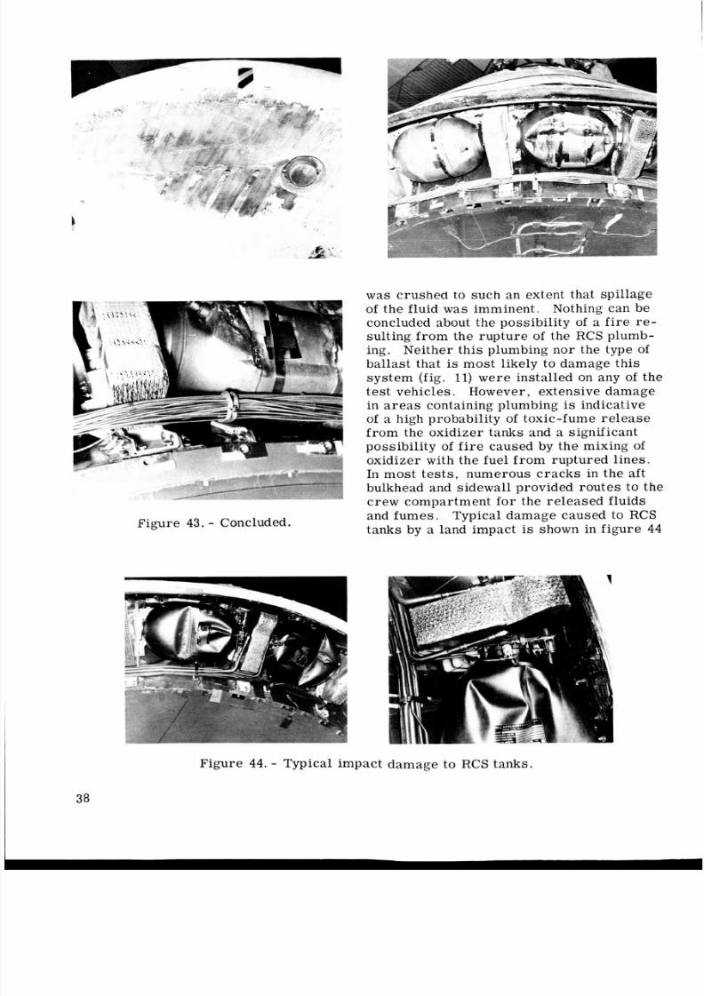
8/7/2019 Apollo Command Module Land-Impact Tests
http://slidepdf.com/reader/full/apollo-command-module-land-impact-tests 47/61
Figure 43. - Concluded.
was crushed to such an extent that s pillage
of the fluid was imminent. Nothing can be
concluded about the possibility of a f i re re-sulting from the r upt ure of the RCS plumb-
ing. Neither t hi s plumbing nor the type of
ballast that is most likely to damage this
syst em (fig. 11) we re insta lled on any of the
tes t vehicles . However, extensive damagein areas containing plumbing is indicativeof a high probability of toxic-fume releasefrom the oxidizer tanks and a significantpossibility of fire caused by the mixing of
oxidizer with the fuel from ruptured lines.
In most tests, numerous cracks in the aftbulkhead and sidewall provided rou tes to the
crew compartment for the release d fluids
and fumes .
tanks by a land impact is shown in figur e 44
Typical damage caused to RCS
Figure 44 . - Typical impact da mag e to RCS tanks.
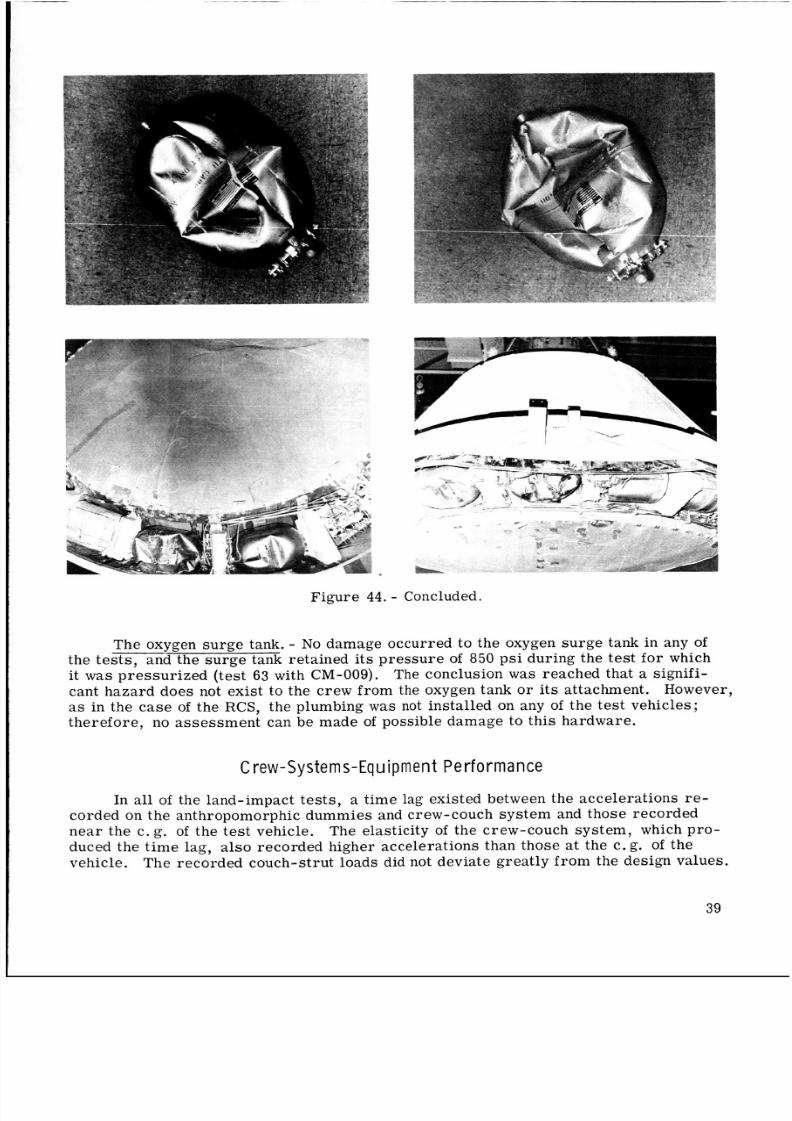
8/7/2019 Apollo Command Module Land-Impact Tests
http://slidepdf.com/reader/full/apollo-command-module-land-impact-tests 48/61
. -Figure 44. - Concluded.
The oxygen su rg e tank. - No damage occurred to the oxygen sur ge tank in any ofthe tests, and the sur ge tank retained its pre ssu re of 850 psi during the test for which
it was pressurized (test 63 with CM-009). The conclusion w a s reached that a signifi-
cant hazard doe s not exis t to the crew from the oxygen tank or its attachment. However,
as in the ca se of the RCS, he plumbing w a s not installed on any of the tes t veh icl es ;
therefore, no asse ssme nt can be made of possible damage to thi s hardware.
C rew -Sy ste m s -Eq u ment Pe rfo rma nce
In all of the land-impact tests, a time lag existed between the acceler ations re -
corded on the anthropomorphic dummie s and crew-couch syst em and those reco rded
nea r the c. g. of the te st vehicle. The elasticity of the crew -couch sys tem, which pro-
duced the tim e lag, al so recorded higher accelerations than those at the c.g. of thevehicle. The re corded couch-strut loads did not deviate greatly fro m the design values.
39
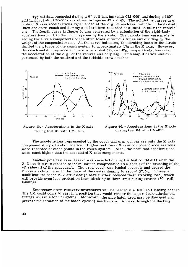
8/7/2019 Apollo Command Module Land-Impact Tests
http://slidepdf.com/reader/full/apollo-command-module-land-impact-tests 49/61
Typical data recorded during a 0" ro ll landing (with CM-009) and during a 180"
ro ll landing (with CM-011) a r e shown in fi gu re s 45 and 46. The solid-line cur ves a r e
plots of X axis accelerations experienced at the c. g. of each te st vehicle. The dashedlines are crew-couch and dummy accelerations recorded at a location near the vehicle
c. g. The four th curve in fig ure 46 w a s generated by a calculation of the rigid-body
accele rations put into the couch syst em by the str uts . The calculations were made by
adding the X axis components of the s tr ut loads at var ious t im es and dividing by the
weight of the suspended mass . A s the curve indicates, the stroking loads of the s tr ut slimited the g fo rc e of the couch syste m to approximately 17g in the X axis. However,
the couch and dummy ac ce le rome te rs reco rde d 37g and 42g, respect ively; however,
the accele ration at the c. g. of the vehicle was only 34g. Thi s amplification w a s ex-perienced by both the unitized and the foldable c rew couches.
50- e h i c l e c . g .
.- C h e s t of c e n t e r d u m m y
N e a r c e n t e r of CGUCh--
40
m I . rn
/ I L \
1 I I I 1 I I0 .01 .02 .03 .04 .05 .06 .0 7 0
T i m e . s e c
V e h i c l e c . g .6 .3 1 se c
--- e a r c e n t e r of c o u c h
--- P e l v i s of c e n t e r d u m m y
A C a l c u l a t e d f r o m s t r u t f o r c e s ,'I -----
2 -2 s t r u t s s t r o ke d t o t h e I
l i m i t in c o m p r e s s i o n I
.0 2 .04 .06 .08 .IO . I 2 . I 4
T i m e , s e c
Figure 45. - Accelerations in the X axis
during te st 31 with CM-009.
Fig ure 46. - Accelerations in the X axis
during test 64 with CM-011.
The acceler ations represente d by the couch and c. g. curv es a r e only the X axis
component at a par tic ula r location. Higher and lower X axis component accele rati ons
were recorded at other points in the couch syst em. Also, t he resultant ac cele rati ons
were much higher than the associated X axis components.
Another potential crew hazard w a s revealed dur ing the te st of CM-011 when the
Z - Z couch struts stroked to their limit in compression as a re su lt of the crush ing of the
-Z sidewall of the spac ecraft. The cre w couch w a s loaded sever ely and caused the
Z axis accelerometer i n the chest of the cente r dummy to rec ord 37.5g. Subsequentmodif ications of the Z - Z st ru t design have fur the r reduced thei r stroki ng load, which
w i l l provide even le ss protection from stroking to the ir limit during seve re 180" rolllandings.
Emergency crew-recovery procedures will be needed if a 180" roll landing occurs.The CM could come to rest in a position that would render the upper-deck-attachment
fittings unusable for uprighting. Moreover, the sid e hatch a r e a may be damaged and
prevent the actuation of the hatch-opening mechanism. Acc ess through the docking
40
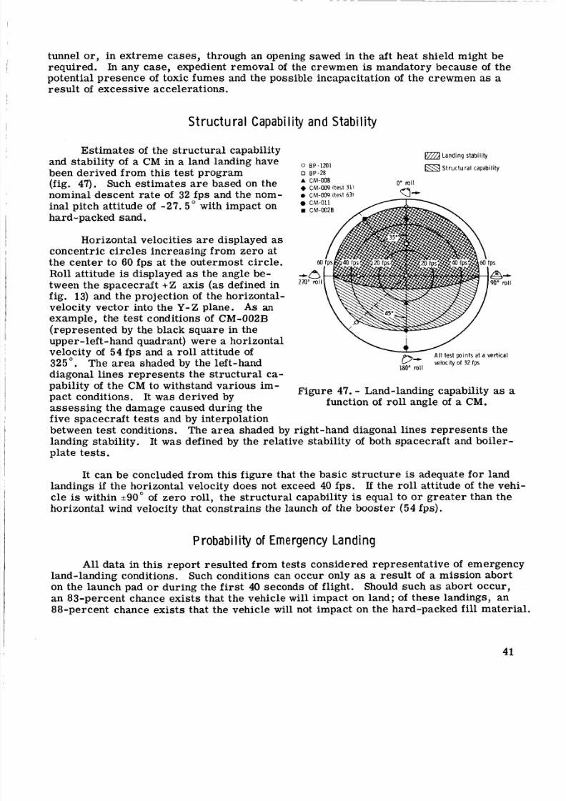
8/7/2019 Apollo Command Module Land-Impact Tests
http://slidepdf.com/reader/full/apollo-command-module-land-impact-tests 50/61
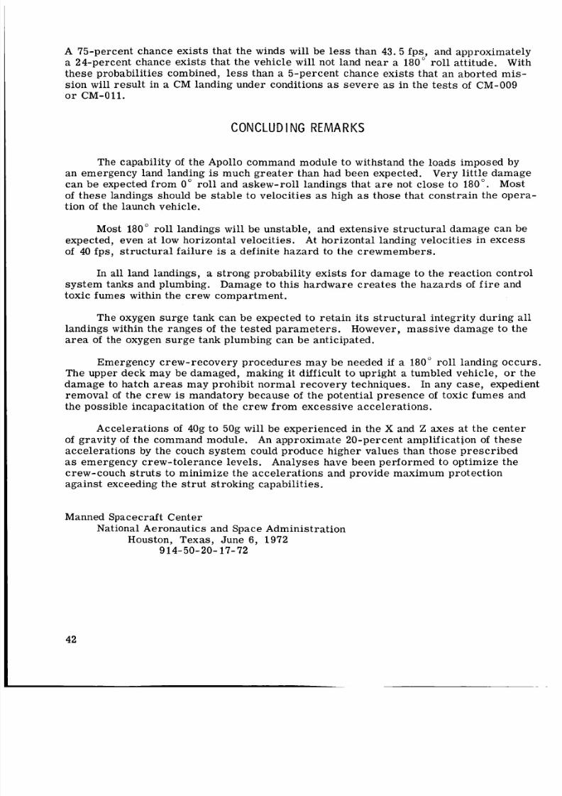
8/7/2019 Apollo Command Module Land-Impact Tests
http://slidepdf.com/reader/full/apollo-command-module-land-impact-tests 51/61
A 75-percent chance exi sts that the winds will be less than 43.5 fps, and approximately
a 24-percent chance exi sts that the vehicle w i l l not land near a 180" ro ll attitude. Withthes e probabilities combined, le s s than a 5-percent chance exists that an aborted mis -
sion will resul t in a CM landing under condit ions as severe as in the tes ts of CM-009
o r CM-011.
CONCLUD I NG REMARKS
The capability of the Apollo command module to withstand the loads imposed byan emergency land landing is much gr ea te r than had been expected. Very little damagecan be expected from 0" rol l and askew-roll landings that ar e not close to 180". Most
of t hese landings should be st ab le to veloci ties as high as those that constrain the opera-tion of the launch vehicle.
Most 180" roll landings w i l l be unstable, and extensive str uct ura l damage can be
expected, even at low horizontal velocities. At horizontal landing velocities in exc ess
of 40 fps, structural failure is a definite hazard to the crewmembers.
In all land landings, a stro ng probability exis ts for damage to the rea ction control
syst em tanks and plumbing. Damage to this har dwar e cr ea te s the haza rds of f ir e and
toxic fumes within the crew compartment.
The oxygen surg e tank can be expected to reta in i ts str uct ura l integrity during all
landings within the ranges of the tested para met ers . However, mas sive damage to the
area of the oxygen su rg e tank plumbing can be anti cipa ted.
Emergency crew-rec overy proc edur es may be needed if a 180" roll landing occurs.The upper deck may be damaged, making it difficult to upright a tumbled vehicle, o r the
damage to hatch areas may prohibit normal recovery techniques. In any case , expedientremoval of the crew is mandatory because of t he potential pre sence of toxic fumes and
the possible incapacitation of the crew fr om excessi ve acce lerations.
Accelerations of 40g to 50g w i l l be experienced in the X and Z axes at the center
of grav ity of the command module. An approximate 20-percent amplif ication of the seaccelerations by the couch system could produce higher values than those prescribed
as emergency crew-tole rance levels. Analyses have been performe d to optimize thecrew-couch st ru ts to minimize the acce lera tions and provide maximum protection
against exceeding the s tr ut stroking capabilities.
Manned Spacecraft CenterNational Aeronautics and Space Administration
Houston, Texas, June 6, 1972914-50-20-17-72
42
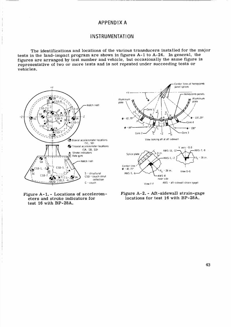
8/7/2019 Apollo Command Module Land-Impact Tests
http://slidepdf.com/reader/full/apollo-command-module-land-impact-tests 52/61
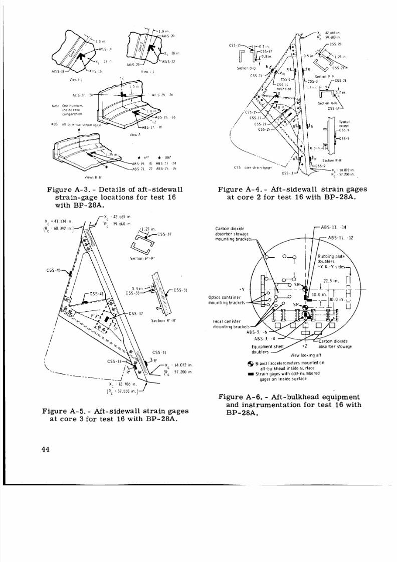
8/7/2019 Apollo Command Module Land-Impact Tests
http://slidepdf.com/reader/full/apollo-command-module-land-impact-tests 53/61
Note Odd numberr
insidecren
A BS a i l bhluhear I i r a tn ia
Vien A
+ 6 9 ~ + 108'
A B S 19 ?u A BS ?j 24
A B S ? I ?2 A B S 25 26
Figure A-3. Details of aft-sidewallstrain-gage locations for test 16
with BP-28A.
r X 42 665 i n
59 600 in
1 1 25 i n
S e c t i o n P ' - P '
Sect ion R ' - R '
Figure A-4. Aft-sidewall st ra in gages
at core 2 for tes t 16 with BP-28A.
C a r b o n d i o x i d e r A B S 13 , 14
O p t i c s c o n t a i n e r
F e c a l c a n i s t e r
E q u i p m e n y + Z a b s o r b e r s t o w ag e
d o u b l e r sV i e w l o o k i n g a l l
@ B i a x ia l a c c e l e r o m e t e r s m o u n t e d o na f t - b u lk h e a d i n s i d e s u r f a c eIt r a i n g a g es w i t h o d d - n u m b e r e d
g ag e s o n i n s i d e s u r f a c e
Figure A-6. Aft-bulkhead equipment
and instrumentation fo r test 16 with
[R c i 57 8 B n
Figure A-5. Aft-sidewall s tra in gages BP- 8A.at core 3 fo r test 16 with BP-28A.
44
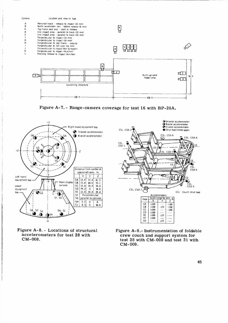
8/7/2019 Apollo Command Module Land-Impact Tests
http://slidepdf.com/reader/full/apollo-command-module-land-impact-tests 54/61
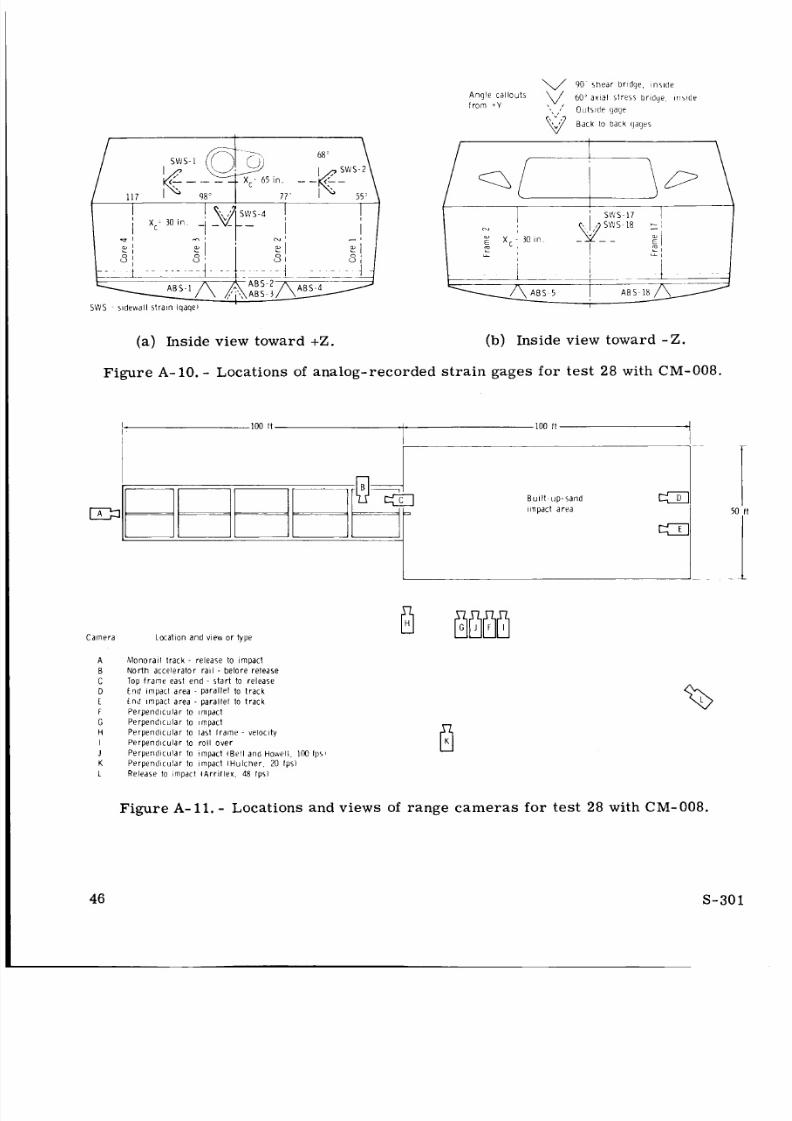
8/7/2019 Apollo Command Module Land-Impact Tests
http://slidepdf.com/reader/full/apollo-command-module-land-impact-tests 55/61
90 s h e a r b r i d g e . insii le
68 ’
11 7 9 8 ” 77 ’
S W S s i d e w a l l s t r a i n l q a q e l
(a) Inside
Figure A - 1 0 . -
A n g l e ca l lou ts
f r o m + Yv,0’ a x i a l s t r e s 5 b r l d q r ir1,ide
,I O u t s i d e g a g e
B a c k 10 b a c k g a g e s
view toward +Z. (b) Inside view toward - Z .
Locations of a nalog-recor ded st ra in gages for test 28 with CM-008.
C a m e r a L o c a t io n a n d v i e w o r t y p e
A
B
C
D
E
F
GH
I
J
KL
M o n o r a i l t r a c k - r e l e a s e t o i m p a c t
N o r t h a c c e le r a t o r r a i l - b e f o r e r e l e a s e
T op f r a m e e a st e n d - s t a r t to r e l e a s e
E n d i m p a c t a r e a - p a r a l l e l t o t r a c k
E n d i m p a c t a r e a - p a r a l l e l to t r a c k
P e r p e n d i c u l a r to i m p a c t
P e r p e n d i c u l a r to i m p a c tP e r p e n d i c u l a r to l a s t f r a m e - ve loc i ty
P e r p e n d i c u l a r to r o l l o v e r
P e r p e n d i c u l a r t o im p a c t lBe11 a n d H o w e l l 100 Ips1
P e r p e n d i c u l a r to i m p a c t I H u l c h e r 20 f p s l
R e l e a s e t o i m p a c t I A r r i l l e x 48 I p s 1
Bu i l t u p - s a n d
i i n p a c t a r e a
B
Figure A-11 . - Locations and views of range camera s for t es t 28 with CM-008.
46S - 3 0 1
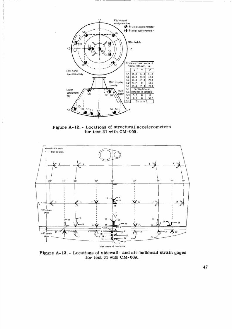
8/7/2019 Apollo Command Module Land-Impact Tests
http://slidepdf.com/reader/full/apollo-command-module-land-impact-tests 56/61
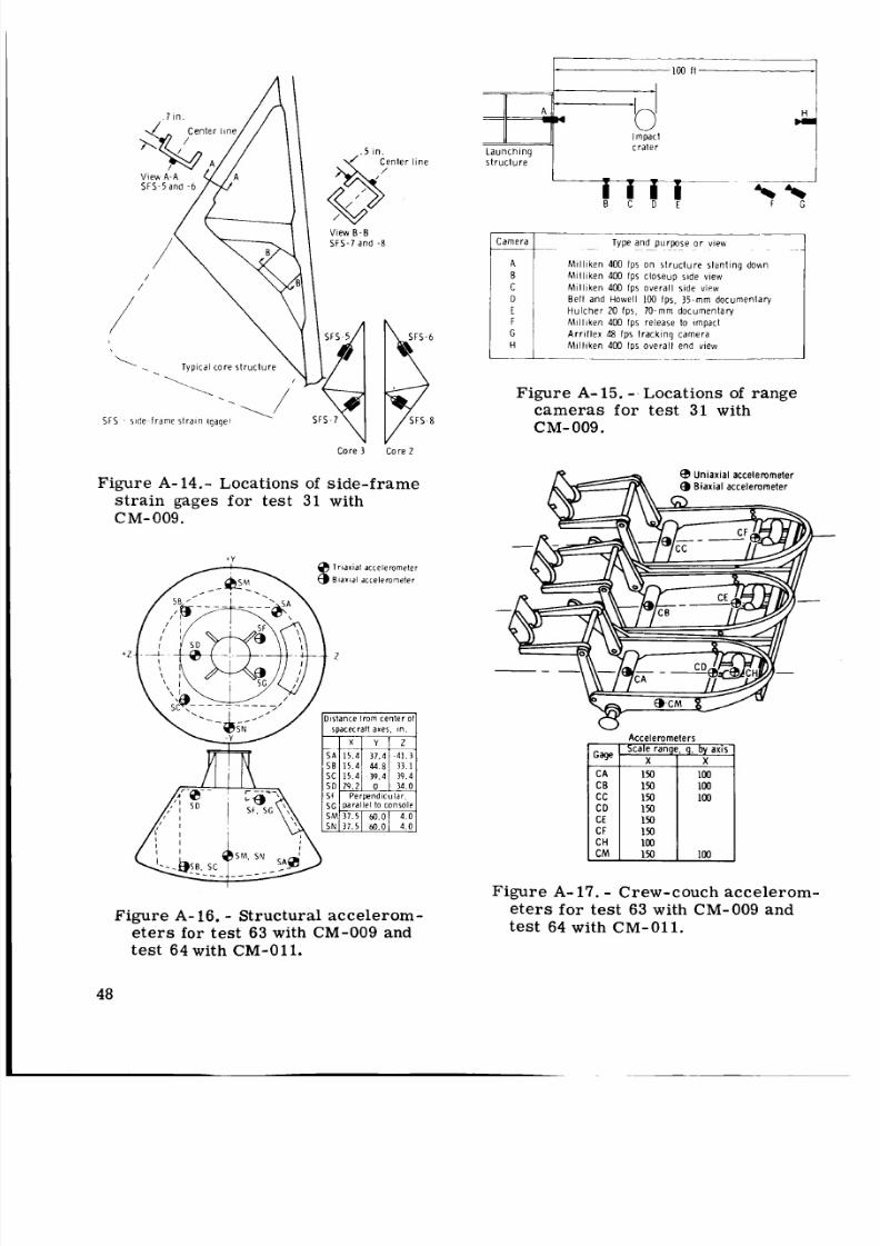
8/7/2019 Apollo Command Module Land-Impact Tests
http://slidepdf.com/reader/full/apollo-command-module-land-impact-tests 57/61
C o r e 3
l i n e
o r e 2
Figure A- 14.- Locations of side-frame
strain gages for test 31 with
C M- 009.
Triaxiat a c c e l e r o m e t e r
8 i a x i a l a c c e l e r o m e t e r
y - I .
I
Figure A- 16. - Structural acceler om-eters for test 63 with CM-009 and
test 64 with CM-011.
48
I m p a c t
L a u n c h i n g c r a t e r
s t r u c t u r e
; 'D
; i
M i l l i k e n 400 I ps o n s t r u c t u r e s l d n t in g d o w n
M i l l i k e n 400 I p s c l o s e u p s i d e v i e w
M i l l i k e n 400 I p s o v e r a l l s i d e VIPW
B e l l a n d H o w e l l 100 I p s 75 m m d o c u m en t a ry
H u l c h e r 20 f p s 7 0 - m m d o c u m e n t a r y
M i l l i k e n 400 I p s r e l e a s e t o i m p a c t
A r r i l l e x 48 I p s t r a c k i n q c a m e r a
M i l l i k e n 400 I p s o v e r a l l e n d v i ew- ~ ~~~ _ _ .Figure A-15. - Locations of range
cameras for t es t 31 with
CM-009.
Figure A- 17. - Crew-couch accelerom-eters fo r test 63 with CM-009 and
test 64 with CM-011.
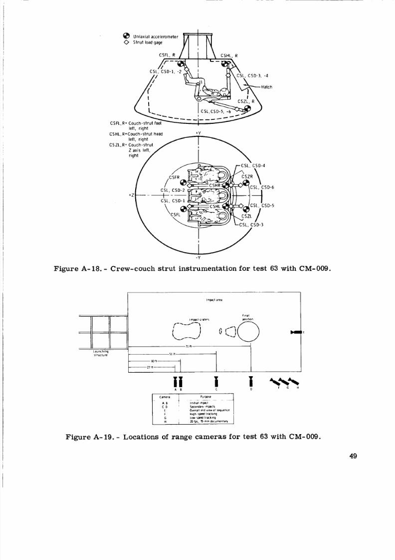
8/7/2019 Apollo Command Module Land-Impact Tests
http://slidepdf.com/reader/full/apollo-command-module-land-impact-tests 58/61
0 U n i a x i a l a c c e l e r o m e t e r
0 t r u t l o ad gage
l e f t . r i q h tC S H L . R - C o u c h - s t r u t h e a d + Y
C S 2 L . R - C o u c h - s t r u t
- Y
Figure A- 18. - Crew-couch st ru t instrumentation for test 63 with CM-009.
Figure A-19. - Locations of ra nge ca me ra s fo r test 63 with CM-009.
49
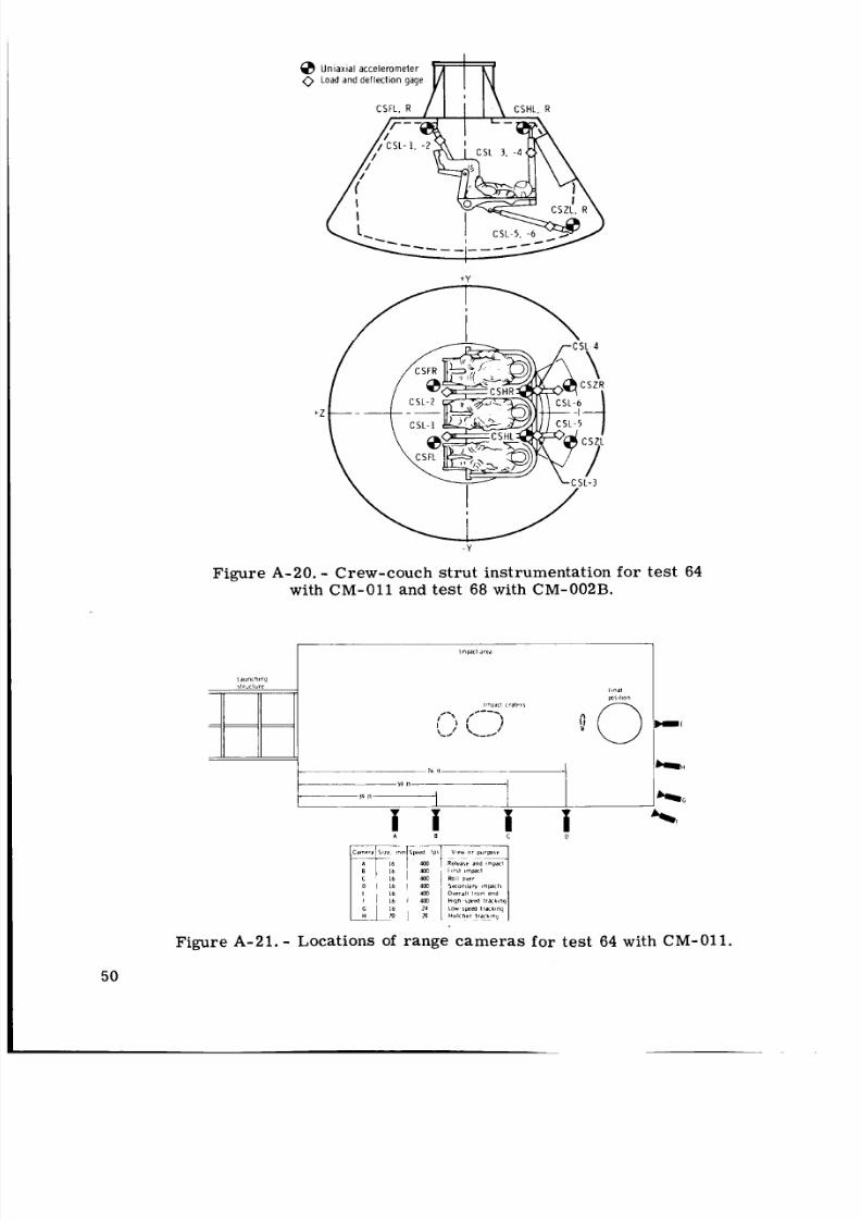
8/7/2019 Apollo Command Module Land-Impact Tests
http://slidepdf.com/reader/full/apollo-command-module-land-impact-tests 59/61
@ U n i a x i a l a c c e l e r o m e t e r
0 o a d a n d d e f l e c t i o n g a ge
- Y
Figure A-20. - Crew-couch s tr ut instrumentation fo r test 64
with CM-011 and test 68 with CM-002B.I 1 I Ii i i i +!
50
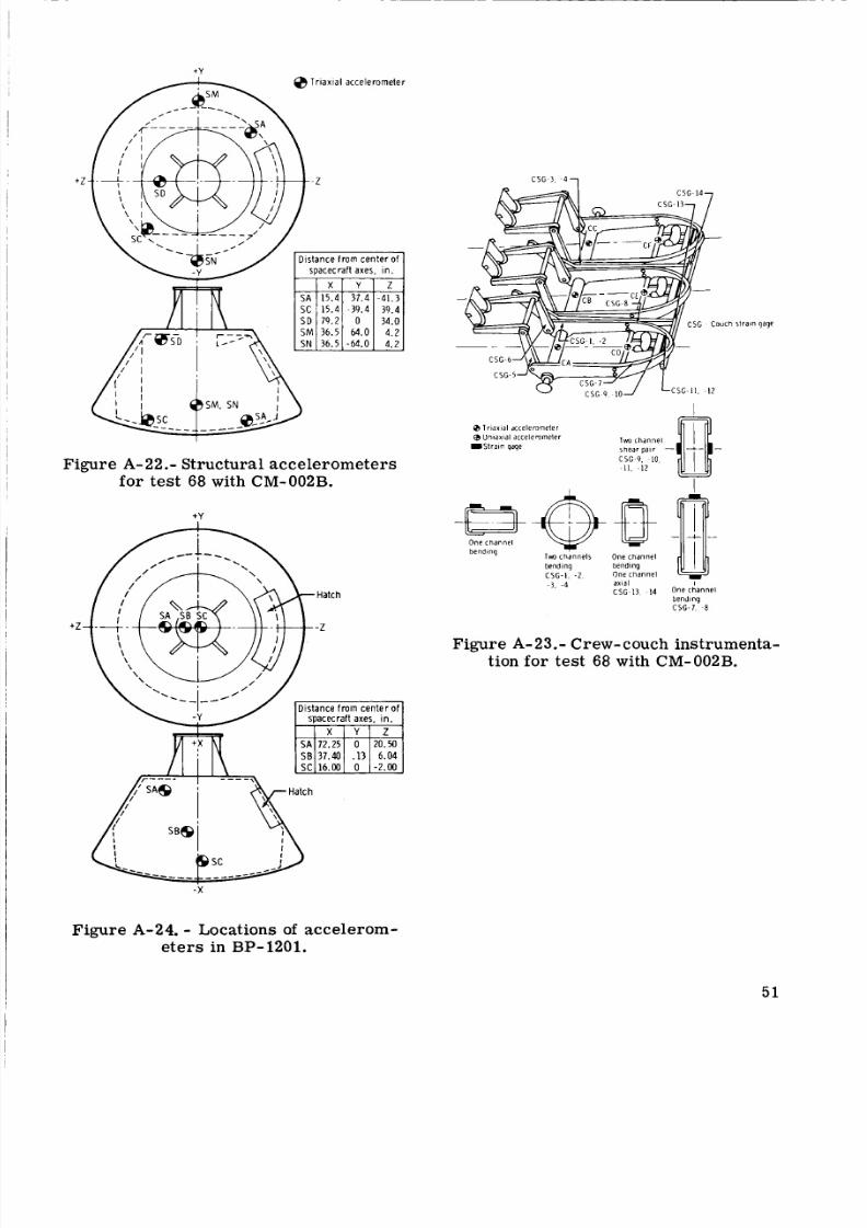
8/7/2019 Apollo Command Module Land-Impact Tests
http://slidepdf.com/reader/full/apollo-command-module-land-impact-tests 60/61
+V
Figure A-22.- Struc tura l acc ele rom ete rs
fo r test 68 with CM-002B.
+ Y
strain gage
0 Ir ia xial dccelerorneter rn
CSG-9. IO.
11. -1 2
8 niaxial accelemmeler
l S l r a i n qaqe
One channe l
bendingTWO channels One channe l
bending bending
CSG-I , -2 . Onechanne l
- 3 , -0 axial
C S G ~ I I14
I
IOne channe l
bending
CSG-1. 8
Figure A-23.- Crew-couc-. inst rumention for test 68 with CM-002B.
:a-
Figure A-24. Locations of accelerom-eters in BP-1201.
5 1
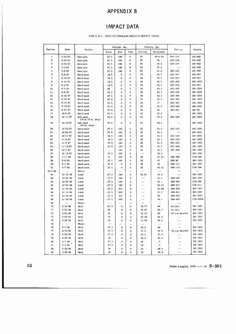
8/7/2019 Apollo Command Module Land-Impact Tests
http://slidepdf.com/reader/full/apollo-command-module-land-impact-tests 61/61
A P P E N D I X B
A t l i l u d e , deg
P i t c h Rol l Y aw
2 7 . 5 180 0
2 7 . 5 180 0
2 7 . 5 180 0
2 7 . 5 180 0
2 7 . 5 180 0
1 8 . 5 0 0
1 8 . 5 0 0
18.5 0 0
1 8 . 5 0 0
36 0 0
3 2 . 5 0 0
2 7 . 5 0 0
2 7 . 5 0 0
2 7 . 5 0 0
2 7 . 5 0 0
2 7 . 5 0 0
2 7 . 5 0 0
2 7 . 5 0 0
2 7 . 5 0 0
2 7 . 5 18 0 0
2 7 . 5 180 0
1 8 . 5 180 0
18.5 180 0
3 7 . 2 180 0
37.2 18 0 0
.. 18 0 0
2 7 . 5 180 0
31 18 0 0
2 7 . 5 18 0 0
2 7 . 5 0 0
2 7 . 5 0 0
_ _. .-
- 2 7 . 5 180 0
- 2 7 . 5 180 0
- 2 7 . 5 180 0
- 2 7 . 5 180 0
- 2 7 . 5 2 7 0 0
- 2 7 . 5 2 2 5 0
- 2 7 . 5 3 1 5 0
- 2 1 . 5 3 2 5 0
.. - _ .-
- 2 7 . 5 0 0
- 22 0 0
36 0 0
36 0 0
36 0 0
2 7 . 5 0 0
_ _ .. _ _
2 7 . 5 0 0
2 7 . 5 0 0
I M P A C T D AT A
T A B L E B-I. - A P O L L O C O M M A ND MO D U LE I M P A C T T E S T S
V e l o c i t y . fp s
V e r t i c a l H c r i z o n t a lFile no.
28 44 lo 4 6 S67-317
2 8 38 S67- 334
2 8 3 9 . 2 S 6 7 - 3 3 7
28 3 7 . 3 _ _28 5 1 . 0 5 6 7 - 5 6 5
38 4 3 . 5 S 6 7 - 4 1 7
38 4 3 . 7 5 6 7 - 4 2 7
38 4 3 . 5 9 5 7 - 4 4 9
38 4 3 . 5 S 6 7 - 4 5 2
38 4 3 . 5 S 6 7 - 4 5 9
38 4 3 . 5 S 6 7 - 4 5 6
38 4 3 . 5 S 6 7 - 4 6 6
32 2 5 . 3 S 6 7 - 4 8 6
3 2 17 S67- 487
32 2 5 . 6 S 6 7 - 4 8 8
32 2 5 S 6 7 - 4 9 1
3 3 37.8 ._
3 3 37.8 S 6 7 - 5 0 6
33 40 . 3 -.
3 2 2 5 . 0 5 6 7 - 5 3 3
3 2 4 3 . 5 -.
32 2 5 . 3 S 6 7 - 5 4 4
3 2 4 3 . 5 5 6 7 - 5 4 0
3 2 2 5 . 3 S 6 7 - 5 4 5
3 2 4 3 . 5 567.600
3 2 4 0 5 S67-600
.._ _ 40. 5
32 2 1 . 2 5 S 6 9 - 0 0 9
32 4 5 S68-83
3 2 4 6 S 6 8 - 1 5 1
32 42 . 55 S68- 17 4
-. _ _ _ _3 2 . 8 1 5 4 . 8 _ _
_ _ 5 1 . 3 S 6 8 - 5 9 6
_ _ 42 I S68-603
.- 5 6 . 3 4 568-613
.. 3 5. 08 S68- 629
.. 5 1 . 3 568-631
-. 4 6 S 6 8 - 6 2 3
54 . I S 6 8 - 4 4 5_
_ _ .. _.
3 2 . 7 7 4 4 No I i lm
3 2 . 6 5 4 3 . I No il m
32 . 16 44 7 0 - m m H u l r h v r
32. 39 56 . 4 .-
3 1 . 9 4 2 9 . 4 _ _.. .- ..
3 2 . 2 4 4 .-
3 1 . 9
3 2 . 5 3 1 . 2 -.
5 6 2 70- n im H u l r h e r
T e s t n o .
1
2
3
4
5
6
7
8
9
10
11
1 2
13
1 4
1 5
16
17
18
1 9
2 0
21
22
23
24
2 5
2 6
27
28
2 9
30
31
32 lo 60
61
62
63
64
65
66
67
68
69
I O
I 1
72
73
74
75
76
77
7 8
D a t e
5/31/67
6 / 23 / 67
6/30/67
7/3/67
7/6/67
8/8/67
8/16/67
8 31/67
9 / 2 1 67
9 / 7 / 6 7
9 / 9 / 6 7
9 / 1 2 ’67
9 / 1 6 / 6 7
9115‘ 67
9 / 1 8 / 6 7
9 27/67
1 0 / 9 / 6 7
10 / 11 / 67
10/13/67
1 0 ’ 2 3 / 6 7
1 0 / 2 4 / 6 7
1 0 l 3 1 ‘67
11 2/67
1 /9 ‘67
I 1 13/67
1 2 / 1 / 6 7
1 2 13/67
1 I 1/68
2 / 8 / 6 8
311 68
3/7/68
_ _10’18 68
10122 68
10/26/68
1 0 /3 1 /6 8
11 ’ 12 68
11 13’68
11/18 68
11 2 6 / 6 8
_ _3 10 / 69
31 2 1 / 69
3 / 2 5 / 6 9
3 / 2 6 6 9
3/28 69
-.
4 / 7 / 6 9
4 / 1 0 / 6 9
4 122 169
S u r f a c e
S a n d p i l e
S a n d p i l e
S a n d p i l e
S a n d p i l e
S a n d p i l e
H a r d s a n d
H a r d s a n d
H a r d s a n d
H a r d s a n d
H a r d s a n d
H a r d s a n d
H a r d s a n d
H a r d s a n d
H a r d s a n d
H a r d s a n d
H a r d s a n d
H a r d s a n d
Sol1 s a n d
So11 s a n d
H a r d s a n d
H a r d s a n d
H a r d s a n d
H a r d s a n d
H a r d s a n d
H a r d s a n d
H a r d s a n d
H a r d s a n d
H a r d s a n d
H a r d s a n d
H a r d s a n d
H a r d s a n d
Wale!
L a nd
L a nd
L a nd
L a nd
L a nd
L a nd
L a nd
L a nd
Wa l e ,
Sa nd
Sa nd
S n d
S i n d
Sa nd
W a l c r
Sa nd
Sa nd
Sa nd
(1 5 lo I 8 in. d e e p )
( 2 4 in. d e e p )
V e h i c l e
BP-002
B P - 0 0 2
B P - 0 0 2
B P - 0 0 2
BP-002
B P - 0 0 1
BP-001
B P - 1 2 0 1
B P - 0 0 1
B P - 1 2 0 1
B P - 1 2 0 1
B P - 1 2 0 1
B P - I 2 0 1
B P - I 2 0 1
B P - I 2 0 1
B P - 2 8
B P - I 2 0 1
BP- 1201
B P - 1 2 0 1
BP - 1201
B P - I 2 0 1
BP-1201
BP-1 2 0 1
B P - 1 2 0 1
BP- 1201
BP- 1201
B P - 1 2 0 1
C M - 0 0 8
B P - 1 2 0 1
B P - 1201
C M - 0 0 9
_ _B P - 1 2 0 1
B P - I 2 0 1
C M - 0 0 9
C M - 0 1 1
B P - 1 2 0 1
B P - 1 2 0 1
B P - 1 2 0 1
C M - 002B
-.
B P - I 2 0 1
B P - I 2 0 1
BP - I 2 0 1
B P - 1 2 0 1
BP-1201
_ _B P - 1 2 0 1
BP- 1201
B P - 1 2 0 1