Embed Size (px)
Citation preview

Apollo 400 Operating Instructions
1
Apollo 400
Operating Instructions
Bracken Hill
South West Industrial Estate
Peterlee
County Durham
SR8 2SW
Co Durham SR8 2SW
England
Tel (+44) 191 5863511
Part Number 380A5531 Revision 2
November 2015
copy 2015 Seaward Electronic Ltd
Apollo 400 Operating Instructions
2
Table of Contents
1 Limited Warranty amp Limitation of Liability 4
2 Disposal of old product 4
3 Certificate of Conformity 5
4 User Notes 6
5 Safety Notes 6
6 Accessories 7
61 Standard Accessories 7
62 Optional Accessories 7
7 Introduction to the Apollo 400 8
8 Getting Started 8
81 Charging New Batteries 8
82 Power On 8
9 User Interface Navigation 9
91 Screen Layout 9
92 Menu Navigation 9
93 Battery Status 10
94 Test Functionality 10
10 Main Menu 11
101 View Saved Data 11
102 User Options 11
103 Bluetooth Setup 12
104 Automatic Test Sequence Editor (PAT Edit) 12
105 Download 13
106 Set Date and Time 13
107 Memory 13
11 Portable Appliance Testing 14
111 Automatic Test Sequence 14
1111 Entering Asset Details 14
1112 The Formal Visual Inspection 14
1113 The Electrical Tests 15
1114 Printing a Label 15
112 Manual Test Interface 15
113 Test Functions 16
Earth Continuity 16
Nulling out the earth continuity test lead(s) resistance 17
Insulation Resistance 17
Substitute Leakage 19
Protective Earth (PE) Conductor Current 20
Touch Current 20
RCD Trip Time 21
IEC Lead Polarity 21
External Leakage Adaptors 21
114 Checkbox Verification 22
12 Updating your Firmware 22
13 Electrical Specification 23
14 Useful Information 25
Apollo 400 Operating Instructions
3
142 Other Information 26
15 Environmental Conditions 27
16 Maintenance 27
161 Charging the battery pack 27
162 Securing the Apollo 400 27
163 Cleaning the Apollo 400 27
164 Replacing the battery pack 28
17 Support 28
Apollo 400 Operating Instructions
4
1 Limited Warranty amp Limitation of Liability
SEAWARD Electronic Limited guarantees this product to be free from defects in material and
workmanship under normal use and service for a period of 2 years (subject to product
registration) provided that the instrument is serviced and calibrated by a Seaward approved
agent in accordance with the manufactures instructions The period of warranty will be
effective at the day of delivery (c) Copyright 2013 All rights reserved Nothing from this edition may be multiplied or made public in any form or
manner either electronically mechanically by photocopying recording or in any manner
without prior written consent from SEAWARD Electronic Limited This also applies to
accompanying drawings and diagrams Due to a policy of continuous development SEAWARD Electronic Limited reserves the right
to alter the equipment specification and description outlined in this publication without prior
notice and no part of this publication shall be deemed to be part of any contract for the
equipment unless specifically referred to as an inclusion within such contract
2 Disposal of old product
This product has been designed and manufactured
with high quality materials and components that can
be recycled and reused
When this symbol is attached to a product it means
the product is covered by the European Directive
200296EC
Please familiarise yourself with the appropriate local separate collection system for electrical
and electronic products Please dispose of this product according to local regulations Do not dispose of this product
along with normal waste material The correct disposal of this product will help prevent
potential negative consequences for the environment and human health
Apollo 400 Operating Instructions
5
3 Certificate of Conformity
As the manufacturer of the apparatus listed declare under our sole responsibility that the
product
Apollo 400
To which this declaration relates are in conformity with the relevant clauses of the following
standards
BS EN 61010-12010 BS EN 61010-1-0302010 BS EN 61010-0312008 Safety requirements for electrical equipment for measurement control and laboratory
use
BS EN 61557-1-2-42007 amp -102001 Electrical safety in low voltage distribution systems up to 1000V ac and 1500V dc ndash
Equipment for testing measuring and monitoring of protective measures BS EN 613262006 Electrical equipment for measurement control and laboratory user-EMC
Requirements Performance The instrument operates within specification when used under the conditions
in the above standards EMC and Safety Standards The product identified above conforms to the requirements of Council Directive 89336EEC
and 7323 EEC Seaward Electronic Ltd is registered under BS EN ISO90012000 Certificate No Q05356
Apollo 400 Operating Instructions
6
4 User Notes
These operating instructions are intended for the use of adequately trained personnel The following symbols are used in these operating instructions and on the Apollo 400
Warning of electrical danger
Indicates instructions must be followed to avoid
danger to persons
Caution follow the documentation This symbol
indicates that the operating instructions must be
adhered to in order to avoid danger
Note Data may be lost or altered in virtually any electronic memory under certain
circumstances Therefore Seaward Electronic assumes no responsibility for financial losses
or claims due to data lost or otherwise rendered unusable whether as a result of abuse
improper use defects disregard of operating instructions or procedures or any allied
causes
5 Safety Notes
This Apollo 400 has been built and tested in accordance with BS EN 61010-1 2010 BS EN 61557 part 1 2 4 and 10 To ensure safe operation of the unit all notes and warnings in these instructions must be
observed at all times
If the Apollo 400 is used in a manner not specified by
these operating instructions then the protection
provided may be impaired
Always ensure that the circuit or appliance under test
is electrically isolated
Do not connect the Apollo 400 to electric circuits with
nominal voltage greater than CAT II 300 V ACDC
The Apollo 400 and all associated cables and leads
must be checked for signs of damage before
equipment is operated Do not use if there are signs of
damage Only use the correct leads supplied with the
Apollo 400
Do not touch test probes beyond the hand barrier on
the test probe
The Apollo 400 may apply high voltage or mains power
to the appliance under test Do not touch conductive
parts of the appliance while tests are active
If the Apollo 400 is being used to determine the
presence or absence of hazardous voltages always
prove the operation of voltage measurement function
before and after use by means of a known voltage
source or proving unit
Do not operate the Apollo 400 in an explosive gas or
dust environment
Apollo 400 Operating Instructions
7
The Apollo 400 has been designed to make
measurements in a dry environment
The Apollo 400 includes a rechargeable battery pack
which is charged while the Apollo 400 is connected to
a mains supply Only a Seaward battery pack should
be connected into the Apollo 400 Disconnect the
Apollo 400 from all leads before opening the battery
compartment
Do not open the Apollo 400 no user serviceable parts
Where safe operation of the Apollo 400 is no longer possible it should be immediately shut
down and secured to prevent accidental operation It must be assumed that safe operation is no longer possible - if the instrument or leads show visible signs of damage or - the instrument does not function or - after long periods of storage under adverse environmental conditions
6 Accessories
61 Standard Accessories
The Apollo 400 is supplied with the following items
Apollo 400 unit 1
Seaward black power lead 1
Test lead red 12m with alligator clip red 1
IEC test lead 1
USB Download Lead 1
62 Optional Accessories
Test lead red 12m with alligator clip black 380A983
Apollo Checkbox 380A953
Apollo carry case 380A952
Professional Seaward kit bag 71G109
Test n Tag Elite Bluetooth Label Printer 339A970
Test n Tag Pro Bluetooth Label Printer 339A980
Bluetooth Barcode Scanner 339A923
PATGuard 3 Software see wwwseawardcoukPG3Trial
110V test adaptor 270A076
3 Phase Leakage Adaptor 5 Star 16A 391A920
3 Phase Leakage Adaptor 5 Star 32A 391A910
3 Phase Adapter Delta 4 pin 16A 415V (for Rpe amp IR) 209A910
3 Phase Adapter Star 5 pin 16A 415V (for Rpe amp IR) 209A911
3 Phase Adapter Delta 4 pin 32A 415V (for Rpe amp IR) 209A912
3 Phase Adapter Star 5 pin 32A 415V (for Rpe amp IR) 209A913
Apollo 400 Operating Instructions
8
7 Introduction to the Apollo 400
Front
1 Test terminal end plate
2 Screen
3 Function keys F1 - F5
4 QWERTY keyboard
5 Power OffStop Key
6 Power OnStart Key
7 Arrow keys
Top
1 EUT test socket
2 IEC Inlet
3 Probe Socket
4 Mains InletProbe Socket 2
5 USB B Port for download
Back
1 Battery compartment
8 Getting Started
81 Charging New Batteries
Before using Apollo 400 for the first time please ensure that you fully charge the unit using
the Seaward black power lead plugged into the mains inlet socket on the top of the tester
82 Power On
This is the Power On button
This is the Power Off button
The first time the Apollo 400 is powered up the User will be automatically set to admin
For further information about changing User see 102 User Options
Apollo 400 Operating Instructions
9
9 User Interface Navigation
91 Screen Layout
1 Information bar
2 Function key icons
3 Test interface sequence table
4 Test interface details
5 Main area
Information Bar This area of the screen shows the Date Time Current User Battery Status and Connection
Status Function Key Icons This area of the screen is used to identify the current action assigned to the function keys Test Interface Sequence Table This area is only displaying in test mode showing the tests within the selected test sequence
This will also show the results and status of the results that have been performed In the
manual mode this table may only show one test Test Interface Details This area is only displayed in test mode showing the details specific to the active test This
includes the measurement an analogue measurement graph the duration and limit Some
tests may show more than more measurement Main Area This area is used to display menu items text fields and forms
92 Menu Navigation
The Apollo is controlled by the function keys The function key icons which are located
above each key are context sensitive and will change depending on the current options
available to you
This is the Home function This will take you back to the
Home screen
This is the Escape function This will return to the previous
screen without saving changes
This is the Accept function This will accept the changes
made in the current screen and move to the next screen
This is the Setup Options function This will take you the
Setup Options screen for the specific function that you are
currently viewing
This is the information key Depending on the current
screen displayed this will display the manual or the Apollo
400 details in the details screen this function will display
the manual
Apollo 400 Operating Instructions
10
This is the MenuOptions key This function will bring up a
context sensitive menu giving the options available for the
current screen
This is the Save key This function is used to save
datachanges that you have made on the current screen
93 Battery Status
While the Apollo 400 is powered on there are periodic checks of the batteries The Apollo
400 will show the status of the batteries
This symbol indicates that the batteries are at 100
capacity
There are several symbols which will display the current
battery voltage When these icons are displayed the
batteries are still good
This symbol indicates that the batteries are low
Although tests performed with the batteries in this state
are still valid all test types may not complete their
intended duration
This symbol indicates that the batteries are discharged
The Apollo 400 will switch itself off after a short period of
time
This symbol indicates that the Apollo 400 is bulk
charging batteries at the full charge current
This symbol indicates that the Apollo 400 is trickle
charging the batteries with reduced charge current This
is known as the Top Up Charge
This symbol indicates that the Apollo 400 has detected a
fault with the battery or battery charger circuit Unplug
the Apollo 400 from the mains supply and wait 2 minutes
before reconnecting the mains If the fault persists then
return the Apollo 400 for service Please note that the battery symbols are not updated in real time and may take a while to
update
94 Test Functionality
There are two buttons which control the starting and stopping of the selected test type
This is the Start Test button This is used to start
electrical tests
This is the Abort Test button This is used to stop
electrical tests
Apollo 400 Operating Instructions
11
10 Main Menu
101 View Saved Data This will allow you to view any data that you have saved in the Apollo 400 By selecting this
icon in the Main Menu you can view a list of all saved Asset IDs by site and location
Use the arrow keys to scroll up and down
This is the Accept function This will open the selected
record
This button allows you to filter records to give a
customised view Select the filters you wish to apply and
press lsquoAcceptrsquo
Once in the record you will be given a list of items under that record such as PAT results and
JPEG images Press Accept to open
This button allows you to delete the selectde record
When viewing a PAT_results record the Menu icon will become available so that you can
view results or print labels When viewing a saved Health amp Safety Form you can edit the report and then save the
changes This will create a new time and date stamped report as well as saving the original
This is the MenuOptions key This function will bring up a
context sensitive menu giving the options available for the
current screen
102 User Options
Apollo 400 has one default user account set up as admin who will have full access to the
product You can add one additional user account to the Apollo 400
This is where you can set up new edit and delete the user account The user can alter their
own screen power save time Auto power down background image avatar and power on
screen and press Save to apply
Use this button to Change User You can then select the
User name to change the current user of the tester
This User Information menu allows users to view their
user type (Expert or Novice)
This is the New User button Here you can set up a new
user account by adding a username and pressing lsquoSave
You can then select their name from the dropdown in the
User Information screen select the type of user (Expert or
Novice
Apollo 400 Operating Instructions
12
This is the Delete User button It will delete whichever
user is currently selected in the lsquoUsernamersquo dropdown
Please note that the admin user cannot be deleted
Press this button to Save changes and return to the
previous screen
103 Bluetooth Setup
Select this icon to setup your Bluetooth accessories to work with the Apollo 400 Switch on
the Bluetooth device you wish to pair with and ensure it is discoverable
This will Bluetooth Search button will search the area for
Bluetooth discoverable devices and return to the previous
menu You can then use the arrow keys to select the
correct Bluetooth ID from the dropdowns for your Bar
Code Scanner Printer or Mobile Device Press lsquoSaversquo
once complete
Press this button to save changes and return to the
previous screen
104 Automatic Test Sequence Editor (PAT Edit)
Although the Apollo 400 comes with a number of pre-defined test sequences you can modify
existing or create new test sequences of their own
From the Menu function key select one of the following options using the arrow keys and the
Accept button
This is the MenuOptions key This function will bring up a
context sensitive menu giving the options available for the
current screen
This is the Accept function This will open the selected
option
Edit Edits the highlighted sequence
Copy Makes a copy of the highlighted test
sequence
Delete Deletes the highlighted test sequence
Add New Adds a new test sequence to the bottom of the
list
Insert New Adds a new test below the highlighted test
sequence
Apollo 400 Operating Instructions
13
When editing a test sequence the following functions are available
This is the Add Test function This will add a new test
directly under the currently selected test
This is the Delete Test function This will delete the
highlighted test from the test sequence
This is the Edit Test function This will edit the
highlighted test
105 Download
Downloading to PATGuard 3
You can download the data from your Apollo to PATGuard 3 software
In the Download menu select To PATGuard in the Download from Apollo dropdown
This button is a way of downloading all data from Apollo
You then need to select one of 2 options from the using dropdown
USB-PC cable
Connect the USB download cable to the USB type B port on the Apollo 400 and to a USB
port on your PC Press Save
Instructions for how to import this download into PATGuard 3 can be found in the PATGuard
3 help files
Bluetooth to Mobile Device
You will need to have a Bluetooth enabled mobile device configured with the Apollo 400 to
use this method See 103 Bluetooth Setup
NB The Apollo 400 does not have the option to download to flash disk
106 Set Date and Time
You can change the date and time in this menu using the arrow keys and number keys
Press this button to save changes and return to the
previous screen
107 Memory
This section will allow you to view how much memory space you have used and how much
is left
This is the Restore button Selecting this will allow you to
clear memory or reset factory settings Select what you
Apollo 400 Operating Instructions
14
would like to restore by pressing the Enter button
Press this button to save changes and return to the
previous screen
11 Portable Appliance Testing
111 Automatic Test Sequence
The Apollo 400 comes with a number of pre-defined test sequences (see Factory Set Test
Sequences) These test sequences can include any combination of electrical tests These
test sequences are performed on equipment to ensure that it meets the safety requirements
outlined in the IET Code of Practice for In-service Inspection and Testing of Electrical
Equipment
1111 Entering Asset Details
Asset ID This is unique identifier for the equipment under
test This can be entered using the keypad or a
barcode scanner (see 103 Bluetooth Setup)
Test
Sequence This is the name of the pre-defined test sequence
which will be performed on the equipment
Site This is the site where the equipment is located
You can choose a site from the dropdown using
the arrow keys or enter a new one
Location This is the location within the site where the
equipment is You can choose a location from the
dropdown using the arrow keys or enter a new
one
Retest Period
(Visual) This is the period in months in which the
equipment should be re-inspected
Retest Period
(Full) This is the period in months in which the
equipment should be re-tested
1112 The Formal Visual Inspection
All pre-set test sequences start with a Visual Inspection
This is the Pass Icon
This is the Fail icon
Apollo 400 Operating Instructions
15
This means that the inspection is not applicable to the
EUT
Pass
All
Pressing the Pass All button will apply a pass to all
relevant inspections and move onto the next test
1113 The Electrical Tests
The Apollo 400 has probe detection that will automatically flag up if you do not have the
correct probe configuration for the test you are trying to perform
During the tests you can see the test duration limit and result on screen see 91 Screen
Layout
Should any test with the sequence fail the sequence will be aborted and you will presented
with the Notes screen by default but this can be changed see 115 PAT Settings
1114 Printing a Label
If you have a TnT Bluetooth printer configured with the Apollo 400 you can print a label after
each test
See 103 Bluetooth Settings to set up a printer
Press this button to go to the print screen and then
again to print a label
This is the Tools function This function allows you to
configure which pre-configured label printer to use
112 Manual Test Interface
The Apollo 400 allows direct access to all of the electrical tests through Manual Mode
Within each test there are a number of function key options
This is the Tools function This function allows you to
configure the test current test type this includes - test duration - test passfail limit
- test typeconnection
Always ensure that you have selected the correct test
connection method in the test for the probe
connections made
Please refer to the Test Functions section for specific information about each test type
Apollo 400 Operating Instructions
16
113 Test Functions
Earth Continuity
Always ensure that the circuit under test is electrically
isolated
Note that measurements can be adversely affected by
parallel resistances of additional circuits or by
transient currents
Connecting a test probe to a hazardous voltage when
a point to point measurement is active will result in
that voltage being present on the other test probe This test is applicable to Class I equipment This test will measure one of the following
resistance between the protective earth terminal in the EUT mains plug and the point
at which a single test probe is applied ndash CLI EUT Continuity
resistance between two test probes ndash Point to Point Continuity resistance between the protective earth terminal in an IEC lead mains plug and the
protective earth terminal in the IEC connector ndash IEC Continuity to ensure that the connection is satisfactory and of sufficiently low resistance The
measurement will be displayed in Ohms There are three possible connection methods for the Earth Continuity test
CLI EUT Continuity
The test is performed between the red
test terminal and the EUT test socket
Point to Point Continuity
This test is performed between the red
test terminal and the black test
terminal Additional test lead is
required
IEC Continuity
The test is performed between the EUT
test socket and the IEC test socket
Always ensure that you have selected the appropriate
test type for the probe connections
Apollo 400 Operating Instructions
17
Selecting test type
In manual PAT test mode the earth continuity test can be switched between a Class I EUT
continuity test and a point to point continuity test as follows
Select Class I Continuity (1) and press the setup key (F3) In the Test Type field select EUT
Continuity Test or Point to Point Continuity Test
During automatic sequences the test type will be as per the test type programmed in the
test sequence Once the correct connections have been made for the selected test type press
the Start button The test will continue until it times out If we wish to abort the current test
press the Stop button Tests on IEC leads CLI EUTs can be performed using a current of
+200mA andor -200mA Tests performed in point to point mode are always performed
using a current +200mA test The direction of the test current can be reversed by switching
the test probes at the point of connection to the appliancecircuit under test
Nulling out the earth continuity test lead(s) resistance
For a more accurate earth continuity measurement the resistance of the test lead(s) can be
zeroed out The feature can be used with both the EUT Continuity and Point to Point
measurement modes
The null facility remains active even if the Apollo 400 is powered off until the feature is
deactivated by pressing the null key again or the Test Type is changed eg if a pair of test
leads are nulled for point to point measurement the null will be deactivated if the Test Type
is changed to EUT Continuity test
Nulling a single test lead
In the manual PAT screen press the setup key (F3) and change the Test Type to EUT
Continuity Test Press save (F4) Connect the earth continuity test lead to the earth continuity
test socket and connect the probe tip to the earth pin of the EUT socket Press Null (F4) to
measure and stored the test lead resistance When the null feature is active the Null icon will
appear on the display
Nulling both test leads
In the manual PAT screen press the setup key (F3) and change the Test Type to Point to
Point Continuity Test Press save (F4) Connect both earth continuity test leads to the earth
continuity test sockets and connect the probe tips together using the supplied alligator clips
Press Null (F4) to measure and stored the test lead resistance When the null feature is active
the Null icon will appear on the display
Insulation Resistance
Always ensure that the circuit under test is electrically
isolated
Connecting a test probe to a hazardous voltage when
a point to point measurement is active will result in
that voltage being present on the other test probe This test is applicable to Class I and Class II equipment This test will measure one of the
following
insulation resistance between live circuits and the protective earth circuit in the EUT
ndash Class I IEC lead insulation test insulation resistance between live circuits and a test probe applied to the EUT ndash
Class II insulation test
Apollo 400 Operating Instructions
18
insulation resistance between two test probes ndash Point to Point Insulation
to ensure that the test points are adequately insulated from one another The measurement
is displayed in MOhms There are three possible connection methods for the Insulation test
CLI and IEC Insulation
The test is performed between the EUT
test socket live and neutral and the EUT
test socket earth pin For IEC leads the other end of the lead
should be connected into the IEC test
socket
CLII Insulation
The test is performed between the EUT
test socket live and neutral and Red
test terminal
Point to Point Insulation
The test is performed between the Red
and Black test terminals both the
continuity test leads are required for
this test Additional test lead is
required
Always ensure that you have selected the correct test
connection method in the test for the probe
connections made
Ensure that the appliance mains switch is in the ON
position
During this test 250V or 500V DC is applied between
the two connections points The 500V DC potential
will be present across the two probe tips during a
Point to Point test
Selecting test type
In manual PAT test mode the insulation test can be switched between a 250V EUT
Insulation test 500V EUT Insulation test 250V Point to Point Insulation test or 500V Point to
Point Insulation test as follows
Apollo 400 Operating Instructions
19
Select Insulation Resistance (2) and press the setup key (F3) In the Test Type field select
the required test
During automatic sequences the test type will be as per the test type programmed in the
test sequence
In manual mode once the correct connections have been made for the selected test type
press the Start button in automatic mode the test will proceed automatically The test will
continue until it times out If we wish to abort the current test press the Stop button The
measurement will be displayed in Mega Ohms If an EUT fails the Insulation test then this may be because of internal filtering or an MOV
Retry the test at 250V or substitute the Insulation test with a Protective Conductor or Touch
Current test
Substitute Leakage
This test is applicable to Class I and Class II equipment This test is used to verify that the
leakage between the mains conductors of the EUT to the EUT earth pin or conductive
accessible surface of the enclosure is to a satisfactory low level There are two possible connection methods for the Substitute Leakage test
CLI and IEC Substitute Leakage
The test is performed between the EUT
test socket live and neutral and the EUT
socket earth pin
For IEC leads the other end of the lead
should be connected into the IEC test
socket
CLII Substitute Leakage The test is performed between the EUT
socket live and neutral and Red test
terminal
During this test 40V AC is applied between the earth pin and both the live and neutral
pins of the appliance mains supply plug In manual mode once the correct connections have been made for the selected test type
press the Start button in automatic mode the test will proceed automatically The test will
continue until it times out If we wish to abort the current test press the Stop button The
measurement will be displayed in milli Amps
This test can prove useful in situations where neither conventional insulation nor flash tests
are acceptable methods of testing the insulation of the appliance
Please note that values for substitute leakage may differ substantially from that of
Apollo 400 Operating Instructions
20
conventional earth leakage tests because of the way that the test is performed (eg it will be
affected by the presence of Neutral-to-Earth suppression capacitors)
Protective Earth (PE) Conductor Current
Always test the earth continuity and insulation
resistance before performing a PE Conductor Current
test
Always check that an appliance with moving parts (eg
an electric drill) is safely mounted to avoid risk of
damage to equipment or personnel
Avoid prolonged repeated use at full load (16A) and
excessive test duration as this may reduce the life of the
unit
Always ensure that appliance and leads which include
RCD protection that the RCD is reset at the beginning
of the test Failure to do so may result in incorrect
measurements being recorded
This test is applicable on Class I
Equipment The Apollo 400 should be connected to
a mains supply The EUT should be
connected into the EUT test socket In manual mode once the correct
connections have been made for the
selected test type press
the Start button in automatic mode the
test will proceed automatically
The test will continue until it times out If we wish to abort the current test press
the Stop button The measurement will be displayed in mA Should the test measurement over range then the test will be aborted immediately and a fail
will be logged
Touch Current
Warning Always test the insulation resistance before
performing a Touch Current test
Warning Always check that an appliance with moving
parts (eg an electric drill) is safely mounted to avoid
risk of damage to equipment or personnel
Attention Avoid prolonged repeated use at full load
(16A) and excessive test duration as this may reduce the
life of the unit
Always ensure that appliance and leads which include
RCD protection that the RCD is reset at the beginning
of the test Failure to do so may result in incorrect
measurements being recorded
Apollo 400 Operating Instructions
21
This test is applicable on Class I and
Class II Equipment The Apollo 400 should be connected to
a mains supply The EUT should be
connected into the EUT socket the red
test terminal should be connected to
point at which the leakage measurement
is required
In manual mode once the correct connections have been made for the selected test type
press the Start button in automatic mode the test will proceed automatically The test will
continue until it times out If we wish to abort the current test press the Stop button The
measurement will be displayed in milli Amps Should the test measurement over range then the test will be aborted immediately and a fail
will be logged
RCD Trip Time
Voltages between the protective conductor and earth
may influence measurements This test will pass a sinusoidal current of 30mA between the EUT socket and the IEC socket
and measure the time it takes for the in-line RCD to trip
Remove all other connections before performing an
RCD test
The Apollo 400 should be connected to
a mains supply The RCD should be
plugged into the EUT test socket and a
connection should be made from the
RCD mains output to the IEC test
socket
Once the correct connections have been made for the selected test type press
the Start button The RCD will be powered and you will be prompted to reset the RCD
When you have reset the RCD the Apollo 400 will count down and then perform the RCD
test the RCD trip time will be displayed The measurement will be displayed in milli seconds
IEC Lead Polarity
The IEC lead input is a test socket and is not intended
to be connected directly to mains Do not connect this
input to the mains supply
The Polarity test checks the wiring
polarity of an IEC lead the IEC should
be plugged into both the EUT and IEC
test sockets
This test can be used to test the wiring polarity of extension leads by plugging the supplied
test IEC lead into the end of the extension lead to complete the circuit to the IEC tests
socket In the automatic sequence editor the Polarity can be added to sequence In the manual
mode the polarity test is already part of a pre-defined test sequence which includes an Earth
Continuity test an Insulation test and the Polarity test
External Leakage Adaptors
Apollo 400 Operating Instructions
22
While using an External Leakage Adaptor the mains
supply will be connected to the EUT through the
adaptor
Ensure that when tests are performed using the
external Leakage Adaptor that the Earth Reverse
option is set to Off
The External Leakage Adaptor test
function is intended to used in
conjunction with the one of Seawards
external leakage adaptors Connect the
external leakage adaptor into the Red
test terminal connect the Earth
Continuity probe into the Black test
terminal
Connect the mains supply and the EUT
to the external leakage adaptor
Note that connecting both the EUT and mains supply to the external leakage adaptor will
connect the mains supply to the EUT
114 Checkbox Verification
A checkbox for the Apollo 400 is available as an optional accessory This can be used to
verify that the Apollo 400 test functions are working correctly When selecting the Checkbox
function follow the onscreen instructions
The Checkbox function will perform a number of
electrical tests Ensure that the onscreen instructions
are followed and that you do not touch the checkbox
during the active tests
12 Updating your Firmware
1 Go to wwwseawardcoukfirmware and save the latest Apollo 400 firmware file on
your PC
2 Power on the unit whilst holding down the F1 button
3 Press F2 to update via PC
4 Follow the onscreen instructions
5 Restart the unit
You can check the firmware version of your tester by
pressing this icon in the Home screen
Apollo 400 Operating Instructions
23
13 Electrical Specification
Earth Continuity
Output Current (Load 2Ω)
Test Voltage (oc)
Measuring Range
Display Range
Resolution Operating Error
Number of tests as per IEC61557-
4
+- 200mA DC with ZAP
gt 4VDC
005 Ωndash 1999 Ω
001 Ω ndash 1999 Ω
001 Ω +-5 + 4 counts
approx 1500
Insulation Test
Test Voltages
Test Current
Test Voltage Accuracy
Measuring Range
Display Range
Resolution Operating Error ( lt 10MΩ ) ( gt 10MΩ )
Number of tests as per IEC61557-
2
500V and 250V DC
1mA minimum for a load of
1kohmvolt lt2mA into sc
+20 -0
010M Ω to 1999M Ω
000M Ω to 1999M Ω
001M Ω +-5 +5 counts +-10 +5 counts approx 1500
Subsitute Leakage Test
Test Voltages
Measuring Range
Display Range
Resolution Operating Error
gt25Vac lt50Vac
020mA to 1999mA
000mA to 1999mA
001mA +-10 +2 digits
Protective Conductor Current
Test Voltage
Display Range
Measurement Range
Resolution
Operating Error
Frequency Response
Supply Voltage maximum
load current 16A
001mA to 1999mA
025mA to 1999mA
001mA
+-5 of reading +- 3 digits
40Hz to 25 kHz
Touch Current
Test Voltage
Display Range
Measurement Range
Resolution
Operating Error
Frequency Response
Supply Voltage maximum
load current 16A
000mA to 350mA
010mA to 350mA
001mA
+-5 of reading +- 2 digits
DC to 25 kHz
Apollo 400 Operating Instructions
24
Load PowerCurrent
Test Voltage
Display Range
Measurement Range
Resolution
Operating Error
Supply Voltage maximum
load current 16A
000 - 1600A
050 - 1600A
001A
+-10 of reading +- 5 digits
Lead Test
Test Voltage
Test 5V DC nominal
Live Neutral checks for oc
sc and crossed
Power Socket Test
Input voltage range
195V ndash 253V AC
Indicates configuration of
voltage potential-
Line potential phase to earth
Line potential phase to neutral
Line potential neutral to earth
RCD Test
Test Voltage
Test Current
Test Current Accuracy
Display Range
Measuring Range
Resolution
Operating Error
230V +10 -15
30mA 150mA rms sinusoidal
30mA -10 +0 150mA +10 -0
0 ndash 2000ms
1ms ndash 2000ms
1ms plusmn1ms
External Leakage
Test Voltage
Display Range
Measuring Range
Resolution
Operating Error
Connected to External
Adapter
0mA - 999mA
025mA - 999mA
001mA +-5 of reading +-2 digits
Apollo 400 Operating Instructions
25
14 Useful Information - 141 Factory Set Test Sequences
Test
Visual Earth Continuity Insulation PE Conductor
Current Touch Current
Substitute
Leakage Wiring
RCD
Trip
Time
Name
Duration
(s)
Limit
(ΩΩ) Duration (s) Voltage
Limit
(MΩΩ)
Duration
(s)
Limit
(mA)
Duration
(s)
Limit
(mA)
Duration
(s)
Limit
(mA)
Limit
(ms)
PortableHandheldIT CLI Yes 5 01 2 500 1
PortableHandheldIT CLII Yes 2 500 2
Fixed Appliance CLI Yes 2 01 5 500 1
Fixed Appliance CLII Yes 5 500 2
IEC Lead 2m Yes 5 02 2 500 1 Yes
13A 5m Surge Protected Lead Yes 5 02 2 250 1 Yes
13A 25m Ext Lead 30mA RCD Yes 5 05 5 08 30
Portable CLI PE Current Yes 5 05 2 250 1 5 08
Portable CLII Touch Current Yes 2 250 2 5 03
IT Equip CLI PE Current Yes 5 01 2 250 1 5 35
IT Equip CLII T ouch Current Yes 2 250 5 03
13A 6m Mains Lead Yes 5 02 2 500 1 Yes
13A 12m Mains Lead Yes 5 03 2 500 1 Yes
13A 24m Mains Lead Yes 5 05 2 500 1 Yes
MovStat CLI 500V Insulation Yes 5 01 2 500 1
MovStat CLII 500V Insulation Yes 2 500 2
MovStat CLI PE Current Yes 5 01 2 250 1 5 35
MovStat CLII Touch Current Yes 2 250 2 5 35
110V HandheldPortable CLI Yes 5 01 2 500 1 2 08
110V HandheldPortable CLII Yes 2 500 2 2 03
110V MovableStationary CLI Yes 5 01 2 500 1 2 35
110V MovableStationary CLII Yes 2 500 2 2 03
110V 25m Lead
RpeampInsulation Yes 5 05 2 500 1
Visual Only Yes
Apollo 400 Operating Instructions
26
142 Other Information
Parameter Default Min Max
Earth Continuity PF limit (Ω) 01 001 1999
Earth Continuity Duration (s) 5 2 30
Insulation Resistance PF limit (MΩ) 1 001 1999
Insulation Resistance Duration (s) 5 2 30
Substitute Leakage PF limit (mA) 075 025 15
Substitute Leakage Duration (s) 5 2 30
IEC Cord Earth Continuity PF limit
(ohms) 01 001 5
IEC Cord Insulation PF limit (MΩ) 1 001 1999
Touch Current PF limit (mA) 025 025 350
Touch Current Duration (s) 5 2 30
PE Conductor Current PF limit (mA) 075 025 1999
PE Conductor Current Duration (s) 5 2 30
External Adapter Continuity (Ω) 01 001 5
External Adapter Leakage (mA) 075 025 999
External Adapter Duration (s) 5 2 30
RCD 30mA trip time (ms) 200 1 2000
RCD 150mA trip time (ms) 40 1 40
Number of tests in a test sequence 1 60
Characters in a test sequence name 1 30
Characters in a User Test name 1 15
Characters in a User Test Unit 15
Total number of Test Sequences 25
Test Results (typical) 2000
Sites 50
Characters in Site name 1 15
Locations 50
Characters in Location name 1 15
Users (including admin) 2
Characters in User name 1 15
Comments List 50
Characters in Comment 25
Characters in Asset ID 1 15
Apollo 400 Operating Instructions
27
15 Environmental Conditions
The Apollo 400 has been designed to perform tests and measurements in a dry environment
Maximum barometric elevation for making measurements is 2000M
Pollution degree 2 according to IEC 60529
Electromagnetic compatibility (EMC) Interference immunity and emitted interference
conforming to IEC 61326-1
Operating temperature range of 0 to 40 degrees C without moisture condensation
Operating Altitude 0 to 2000 metres
16 Maintenance
161 Charging the battery pack
The battery pack will be charged whenever the Apollo 400 is connected to the mains supply
regardless of whether it is switched on or off
The typical charging current is set to 500mA but this may vary as the instrument also
includes pre-charge and top up charge modes
When no tests are being performed the battery pack will be fully re-charged after 7 hours
162 Securing the Apollo 400
Under certain conditions safe operation of the Apollo 400 can no longer be assumed
Visible damage of the instrument case
Incorrect measurement results
Recognisable abuse to the instrument due to prolonged storage under improper conditions
Recognisable abuse to the instrument due to extraordinary transportation stress
In these case the Apollo 400 should be immediately switched off disconnected from any test
and measurement function and secured to prevent any further use
163 Cleaning the Apollo 400
Clean the external case of the Apollo 400 with a dry clean cloth
Avoid using solvents and abrasive scouring agents to clean the external case of the Apollo
400
Apollo 400 Operating Instructions
28
164 Replacing the battery pack
Before opening the Apollo 400 battery compartment
ensure that all test leads and accessories are
disconnected
Power off the instrument
Disconnect all test leads and accessories
Position the instrument face down and remove the screw holding the battery compartment
cover in place
Remove the battery compartment cover
Remove the battery pack from the compartment and unplug the 4 way connector
Connect the 4 way connector of the new battery to the 4 way header in the battery
compartment put the battery pack into the compartment
Relocate the battery compartment cover and fasten in position with the battery compartment
screw
ONLY USE A REPLACEMENT BATTERY PACK THAT HAS BEEN SUPPLIED BY SEAWARD
OR A SEAWARD APPROVED DISTRIBUTOR
17 Support
The Apollo 400 must be registered with Seaward before support will be made available For Technical Support contact Tel (+44) 191 587 8718
For help or advice on Service and Calibration contact
CalibrationHouse Seaward Electronic Bracken Hill South West Industrial Estate Peterlee Co Durham SR8 2SW England Tel (+44) 191 5878739 (+44) 191 5878737 Email serviceseawardcouk
Calibration House is part of the Seaward Group
Apollo 400 Operating Instructions
29
171 Register your product here-
wwwseawardcouk 172 Calibration Services-
wwwcalibrationhousecouk Bracken Hill South West Industrial Estate Peterlee County Durham SR8 2SW Co Durham SR8 2SW England Tel (+44) 191 5863511 Some icons provided by Fat Cow (httpwwwfatcowcomfree-icons) Based in part on the work of the Qwt project (httpqwtsfnet)
Apollo 400A simple no-nonsense PAT tester with fast data entry and storage for up to 2000appliance records
Key Featuresn High definition colour displayn Store 2000 appliance recordsn Remote data transfer from field to office n Bluetooth connectivity
Electrical Test Functionsn Low current earth continuity test guaranteeing accurate measurement n Point to point testing (earth continuity and insulation resistance)n Insulation resistancen IEC lead testn Protective conductor currentn Touch currentn Load powercurrentn Alternative leakage currentn RCD testn Power socket test
Ideal Forn Electrical Contractorsn Facilities Managersn Operations Managers
Apollo 400 offers simple electrical safety testing with straightforward data entryusing the intuitive QWERTY keypad
A comprehensive range of electrical safety tests ensure compliance with theIET 4th Edition Code of Practice whilst remote data transfer and USB downloadmakes data management easy and efficient
The Apollo 400 is ideal for mid-volume PAT testing where detailed records arerequired
Streamline the PAT testing process further by using the Apollo 400 with acompatible label printer barcode scanner and PATGuard 3 software
wwwseawardcoukapollo400
Tel +44 (0) 191 587 8741Email salesseawardcouk
Requires optional accessory (part number 380A983)
Straightforward PAT testing with simple data managementApollo 400 offers a comprehensive suite of electrical safetytests to enable any workplace appliance to be tested including3-phase equipment fixed appliances and RCDs
The QWERTY keypad enables asset information to be entered quicklyand easily while a large colour display with an intuitive menu structure makesthe Apollo 400 simple to grasp Lightweight and small in size with battery or mainspower modes the Apollo 400 is good to go in seconds allowing more appliances to betested without downtime for boot-up or a battery re-charge
Superb software for total traceabilityApollo 400 has an internal memory capable of storing up to 2000electrical test records Its compatibility with Seawardrsquos PATGuard 3software means that complete test records are easily managed ona PC
Transfer data to the PC remotely using the Bluetooth function anda smartphone or download the results via a USB cable directly toa PC Once downloaded to PATGuard 3 it is easy to keep track ofthe history of test and inspections as well as produce reportscertificates and invoices ndash offering total peace of mind and quickereasier management of scheduling inspections and tests
Download a free trial at wwwseawardcoukpg3trial
wwwseawardcoukapollo400
Tel +44 (0) 191 587 8741Email salesseawardcouk
additional accessory required for point to point testing
u Accessory BundlesThe Apollo 400 is available to buy with a selectionof optional accessory bundles to help you get themost out of your tester
Apollo 400 is supplied as standard with a UKAScalibration certificate and a 2 yearmanufacturerrsquos warranty (subject to terms andconditions)
Greater efficiency through useful accessoriesAs with many Seaward PAT testers the Apollo 400 is compatible with arange of printers and barcode scanners further speeding up the processof asset recognition testing and labelling
Also available in this range
A multi-tasking and fully customisable PAT with additionalhealth and safety features and on-board camera forunrivalled record keeping
Apollo 600 includes a universal risk assessment tool andthe ability to store up to 50000 appliance records plus2000 images - providing visual evidence of testenvironments perfect for advanced record-keeping inorganisations with high-volume workplace test andinspection routines
Apollo 600Multi-tasking PAT tester with on-board camera
wwwseawardcoukapollo400
Tel +44 (0) 191 587 8741Email salesseawardcouk
A powerful PAT tester with a built-in PAT retest calculatorand flexible user-configurable sequences for recordingany non-electrical workplace test or inspection
The ability to customise a number of settings and a largememory to store up to 10000 appliance records makesthe Apollo 500 a versatile and dependable tool for highvolume PAT testing
Apollo 500A fast amp fully customisable and versatile PAT tester
Optional accessory bundles available Part Number
Elite Bundle n Test n Tag Elite 2 rugged portable printer
n Test n Tag printer labels x 4
n Bluetooth barcode scanner
n Apollo kit carry case
n 110V adapter
Includes Apollo 400 tester
380A978
Elite Bundle +Software
PLUS PATGuard 3 software 1yr licence 380A979
Pro Bundle n Test n Tag Pro lightweight portable printer
n Test n Tag printer labels x 4
n Bluetooth barcode scanner
n Apollo kit carry case
n 110V adapter
Includes Apollo 400 tester
380A980
Pro Bundle +Software PLUS PATGuard 3 software 1yr licence 380A981
wwwseawardcoukapollo400
Tel +44 (0) 191 587 8741Email salesseawardcouk
Apollo 400 Apollo 500 Apollo 600
General Features
Battery amp mains powered n n n
Colour Screen amp QWERTY keypad n n n
Large internal memory 2000 records 10000 records 50000 records
Scanner amp printer compatible n n n
Password controlled user accounts n n
Set up multiple user accounts with varyinglevels of privileges
n n
Clone facility to set up multiple testers n n
Checkbox supplied as standard n n
On-board user manual n n
Test amp InspectionFeatures
Auto-increment asset ID n n
PAT Setup option to allow for custom menus n n
Enter asset description after test usingkeypad or barcode scanner
n n n
Comprehensive electrical safety test features n n n
Point to point measurement (Rpe amp IR)
n
(optional
accessory
required)
n n
User configurable electrical testvisualinspection sequences 25 100 100
User set sites amp locations 50 100 100
Risk based retest period calculator n n
User definable comments lines against testrecords
n n
Configurable checklists for any workplacetest or inspection (user tests)
n n
On-board camera n
Universal risk assessment n
Health amp safety certificates n
Data Transfer
Bluetooth connectivity n n n
Barcode scanner connectivity n n n
Print Pass amp Fail labels n n n
Add your company logo to labels n n
Select from various label formats to print n n
Remote data transfer via mobile device n
(Android only)
n
(Android only)
n
(Android and iOS)
Download to PC via USB cable n n n
Filter results to be downloaded n n
Upload previous results to tester for retest n n
Data transfer via USB flash drive n
Apollo Series Comparison Chart
PAT TESTS
Earth ContinuityTest Current +- 200mA DC Display Range 001 ndash 1999ΩPass Value User Defined
Insulation ResistanceTest Voltage 500V 250VDC 1mA nominalDisplay Range 001MΩ - 1999MΩPass Value User Defined
IEC Lead TestTest Voltage 5VAC nominalTest Live Neutral Checks for oc sc and crossed
Protective Conductor CurrentLoad
Test Voltage Supply voltage maximum load current 16A Display Ranges 001mA to 1999mA Pass Value User Defined
Touch Current
Test Voltage Supply Voltage maximum load current 16ADisplay Range 000 ndash 350mA Pass Value User defined
Load PowerCurrent
Test Voltage Supply Voltage maximum load current 16ATest Duration Programmable up to a maximum of 255s depending on load ie max duration is reduced for high loadsDisplay Range 000kVA ndash 400kVA 000A ndash 1600A
Alternative Leakage Current
Test Voltages gt25VAC lt50VAC Display Range 000mA to 1999mAPass Value User Defined
RCD Test
Test Voltage 230V +10 -15Test Current 30mA 150mA rms sinusoidalDisplay Range 0ms - 2000ms (30mA) 0-40ms (150mA)Test Method Internal isolation to avoid tripping distribution board RCD
Power Socket Test
Voltage Range 207V ndash 253VACIndicates configuration of voltage potential-Line potential phase to earthLine potential phase to neutralLine potential neutral to earth
General
Memory Size 2000 recordsWeight 15kgDimensions 230mm x 150mm x 100mmPower Source Mains or rechargeable battery pack
Standard Accessories (supplied with Apollo 400)30 day free trial of PATGuard 3 software 1x red test lead and probe with crocodile clip05m IEC leadMains power leadUSB download cableQuick start guideUKAS calibration certificate
Optional Accessories Test n Tag Elite 2 Bluetooth printer with roll of small labels (339A995)Test n Tag Pro Bluetooth printer with roll of small labels (339A987)Roll of small labels (approx 350 off 52 x 25mm labels) (339A947)Additional black test lead and probe with crocodile clip (for point to point testing) (380A983)Bluetooth barcode scanner (339A923)110V test adaptor (270A076)110V to IEC adapter (344A050)Apollo checkbox (380A953)3 Phase Leakage Adaptor 5 Star 16A (391A920)3 Phase Leakage Adaptor 5 Star 32A (391A910)3 Phase Adapter Delta 4 pin 16A 415V (for Rpe amp IR) (209A910)3 Phase Adapter Star 5 pin 16A 415V (for Rpe amp IR) (209A911)3 Phase Adapter Delta 4 pin 32A 415V (for Rpe amp IR) (209A912)3 Phase Adapter Star 5 pin 32A 415V (for Rpe amp IR) (209A913)Professional Seaward kit bag (71G109)Apollo carry case (380A952)PATGuard 3 software ndash download 30 day free trial atwwwseawardcoukpg3trial
Part NumbersApollo 400 standard package 380A920Apollo 400 with Elite accessory bundle 380A978Apollo 400 with Elite accessory bundle amp PATGuard 3 one year licence380A979Apollo 400 with Pro accessory bundle 380A980Apollo 400 with Pro accessory bundle amp PATGuard 3 one year licence380A981
TrainingSeaward offer a range of PAT testing courses including City amp GuildsGo to wwwseawardcouktraining for more information
Services2 year warranty (subject to terms and conditions available atwwwseawardcoukwarranty24)Service amp Calibration by CalibrationhouseGo to wwwcalibrationhousecom for more information
Technical Specifications
Part of
Rev 12
wwwseawardcoukapollo400
Tel +44 (0) 191 587 8741Email salesseawardcouk

Apollo 400 Operating Instructions
2
Table of Contents
1 Limited Warranty amp Limitation of Liability 4
2 Disposal of old product 4
3 Certificate of Conformity 5
4 User Notes 6
5 Safety Notes 6
6 Accessories 7
61 Standard Accessories 7
62 Optional Accessories 7
7 Introduction to the Apollo 400 8
8 Getting Started 8
81 Charging New Batteries 8
82 Power On 8
9 User Interface Navigation 9
91 Screen Layout 9
92 Menu Navigation 9
93 Battery Status 10
94 Test Functionality 10
10 Main Menu 11
101 View Saved Data 11
102 User Options 11
103 Bluetooth Setup 12
104 Automatic Test Sequence Editor (PAT Edit) 12
105 Download 13
106 Set Date and Time 13
107 Memory 13
11 Portable Appliance Testing 14
111 Automatic Test Sequence 14
1111 Entering Asset Details 14
1112 The Formal Visual Inspection 14
1113 The Electrical Tests 15
1114 Printing a Label 15
112 Manual Test Interface 15
113 Test Functions 16
Earth Continuity 16
Nulling out the earth continuity test lead(s) resistance 17
Insulation Resistance 17
Substitute Leakage 19
Protective Earth (PE) Conductor Current 20
Touch Current 20
RCD Trip Time 21
IEC Lead Polarity 21
External Leakage Adaptors 21
114 Checkbox Verification 22
12 Updating your Firmware 22
13 Electrical Specification 23
14 Useful Information 25
Apollo 400 Operating Instructions
3
142 Other Information 26
15 Environmental Conditions 27
16 Maintenance 27
161 Charging the battery pack 27
162 Securing the Apollo 400 27
163 Cleaning the Apollo 400 27
164 Replacing the battery pack 28
17 Support 28
Apollo 400 Operating Instructions
4
1 Limited Warranty amp Limitation of Liability
SEAWARD Electronic Limited guarantees this product to be free from defects in material and
workmanship under normal use and service for a period of 2 years (subject to product
registration) provided that the instrument is serviced and calibrated by a Seaward approved
agent in accordance with the manufactures instructions The period of warranty will be
effective at the day of delivery (c) Copyright 2013 All rights reserved Nothing from this edition may be multiplied or made public in any form or
manner either electronically mechanically by photocopying recording or in any manner
without prior written consent from SEAWARD Electronic Limited This also applies to
accompanying drawings and diagrams Due to a policy of continuous development SEAWARD Electronic Limited reserves the right
to alter the equipment specification and description outlined in this publication without prior
notice and no part of this publication shall be deemed to be part of any contract for the
equipment unless specifically referred to as an inclusion within such contract
2 Disposal of old product
This product has been designed and manufactured
with high quality materials and components that can
be recycled and reused
When this symbol is attached to a product it means
the product is covered by the European Directive
200296EC
Please familiarise yourself with the appropriate local separate collection system for electrical
and electronic products Please dispose of this product according to local regulations Do not dispose of this product
along with normal waste material The correct disposal of this product will help prevent
potential negative consequences for the environment and human health
Apollo 400 Operating Instructions
5
3 Certificate of Conformity
As the manufacturer of the apparatus listed declare under our sole responsibility that the
product
Apollo 400
To which this declaration relates are in conformity with the relevant clauses of the following
standards
BS EN 61010-12010 BS EN 61010-1-0302010 BS EN 61010-0312008 Safety requirements for electrical equipment for measurement control and laboratory
use
BS EN 61557-1-2-42007 amp -102001 Electrical safety in low voltage distribution systems up to 1000V ac and 1500V dc ndash
Equipment for testing measuring and monitoring of protective measures BS EN 613262006 Electrical equipment for measurement control and laboratory user-EMC
Requirements Performance The instrument operates within specification when used under the conditions
in the above standards EMC and Safety Standards The product identified above conforms to the requirements of Council Directive 89336EEC
and 7323 EEC Seaward Electronic Ltd is registered under BS EN ISO90012000 Certificate No Q05356
Apollo 400 Operating Instructions
6
4 User Notes
These operating instructions are intended for the use of adequately trained personnel The following symbols are used in these operating instructions and on the Apollo 400
Warning of electrical danger
Indicates instructions must be followed to avoid
danger to persons
Caution follow the documentation This symbol
indicates that the operating instructions must be
adhered to in order to avoid danger
Note Data may be lost or altered in virtually any electronic memory under certain
circumstances Therefore Seaward Electronic assumes no responsibility for financial losses
or claims due to data lost or otherwise rendered unusable whether as a result of abuse
improper use defects disregard of operating instructions or procedures or any allied
causes
5 Safety Notes
This Apollo 400 has been built and tested in accordance with BS EN 61010-1 2010 BS EN 61557 part 1 2 4 and 10 To ensure safe operation of the unit all notes and warnings in these instructions must be
observed at all times
If the Apollo 400 is used in a manner not specified by
these operating instructions then the protection
provided may be impaired
Always ensure that the circuit or appliance under test
is electrically isolated
Do not connect the Apollo 400 to electric circuits with
nominal voltage greater than CAT II 300 V ACDC
The Apollo 400 and all associated cables and leads
must be checked for signs of damage before
equipment is operated Do not use if there are signs of
damage Only use the correct leads supplied with the
Apollo 400
Do not touch test probes beyond the hand barrier on
the test probe
The Apollo 400 may apply high voltage or mains power
to the appliance under test Do not touch conductive
parts of the appliance while tests are active
If the Apollo 400 is being used to determine the
presence or absence of hazardous voltages always
prove the operation of voltage measurement function
before and after use by means of a known voltage
source or proving unit
Do not operate the Apollo 400 in an explosive gas or
dust environment
Apollo 400 Operating Instructions
7
The Apollo 400 has been designed to make
measurements in a dry environment
The Apollo 400 includes a rechargeable battery pack
which is charged while the Apollo 400 is connected to
a mains supply Only a Seaward battery pack should
be connected into the Apollo 400 Disconnect the
Apollo 400 from all leads before opening the battery
compartment
Do not open the Apollo 400 no user serviceable parts
Where safe operation of the Apollo 400 is no longer possible it should be immediately shut
down and secured to prevent accidental operation It must be assumed that safe operation is no longer possible - if the instrument or leads show visible signs of damage or - the instrument does not function or - after long periods of storage under adverse environmental conditions
6 Accessories
61 Standard Accessories
The Apollo 400 is supplied with the following items
Apollo 400 unit 1
Seaward black power lead 1
Test lead red 12m with alligator clip red 1
IEC test lead 1
USB Download Lead 1
62 Optional Accessories
Test lead red 12m with alligator clip black 380A983
Apollo Checkbox 380A953
Apollo carry case 380A952
Professional Seaward kit bag 71G109
Test n Tag Elite Bluetooth Label Printer 339A970
Test n Tag Pro Bluetooth Label Printer 339A980
Bluetooth Barcode Scanner 339A923
PATGuard 3 Software see wwwseawardcoukPG3Trial
110V test adaptor 270A076
3 Phase Leakage Adaptor 5 Star 16A 391A920
3 Phase Leakage Adaptor 5 Star 32A 391A910
3 Phase Adapter Delta 4 pin 16A 415V (for Rpe amp IR) 209A910
3 Phase Adapter Star 5 pin 16A 415V (for Rpe amp IR) 209A911
3 Phase Adapter Delta 4 pin 32A 415V (for Rpe amp IR) 209A912
3 Phase Adapter Star 5 pin 32A 415V (for Rpe amp IR) 209A913
Apollo 400 Operating Instructions
8
7 Introduction to the Apollo 400
Front
1 Test terminal end plate
2 Screen
3 Function keys F1 - F5
4 QWERTY keyboard
5 Power OffStop Key
6 Power OnStart Key
7 Arrow keys
Top
1 EUT test socket
2 IEC Inlet
3 Probe Socket
4 Mains InletProbe Socket 2
5 USB B Port for download
Back
1 Battery compartment
8 Getting Started
81 Charging New Batteries
Before using Apollo 400 for the first time please ensure that you fully charge the unit using
the Seaward black power lead plugged into the mains inlet socket on the top of the tester
82 Power On
This is the Power On button
This is the Power Off button
The first time the Apollo 400 is powered up the User will be automatically set to admin
For further information about changing User see 102 User Options
Apollo 400 Operating Instructions
9
9 User Interface Navigation
91 Screen Layout
1 Information bar
2 Function key icons
3 Test interface sequence table
4 Test interface details
5 Main area
Information Bar This area of the screen shows the Date Time Current User Battery Status and Connection
Status Function Key Icons This area of the screen is used to identify the current action assigned to the function keys Test Interface Sequence Table This area is only displaying in test mode showing the tests within the selected test sequence
This will also show the results and status of the results that have been performed In the
manual mode this table may only show one test Test Interface Details This area is only displayed in test mode showing the details specific to the active test This
includes the measurement an analogue measurement graph the duration and limit Some
tests may show more than more measurement Main Area This area is used to display menu items text fields and forms
92 Menu Navigation
The Apollo is controlled by the function keys The function key icons which are located
above each key are context sensitive and will change depending on the current options
available to you
This is the Home function This will take you back to the
Home screen
This is the Escape function This will return to the previous
screen without saving changes
This is the Accept function This will accept the changes
made in the current screen and move to the next screen
This is the Setup Options function This will take you the
Setup Options screen for the specific function that you are
currently viewing
This is the information key Depending on the current
screen displayed this will display the manual or the Apollo
400 details in the details screen this function will display
the manual
Apollo 400 Operating Instructions
10
This is the MenuOptions key This function will bring up a
context sensitive menu giving the options available for the
current screen
This is the Save key This function is used to save
datachanges that you have made on the current screen
93 Battery Status
While the Apollo 400 is powered on there are periodic checks of the batteries The Apollo
400 will show the status of the batteries
This symbol indicates that the batteries are at 100
capacity
There are several symbols which will display the current
battery voltage When these icons are displayed the
batteries are still good
This symbol indicates that the batteries are low
Although tests performed with the batteries in this state
are still valid all test types may not complete their
intended duration
This symbol indicates that the batteries are discharged
The Apollo 400 will switch itself off after a short period of
time
This symbol indicates that the Apollo 400 is bulk
charging batteries at the full charge current
This symbol indicates that the Apollo 400 is trickle
charging the batteries with reduced charge current This
is known as the Top Up Charge
This symbol indicates that the Apollo 400 has detected a
fault with the battery or battery charger circuit Unplug
the Apollo 400 from the mains supply and wait 2 minutes
before reconnecting the mains If the fault persists then
return the Apollo 400 for service Please note that the battery symbols are not updated in real time and may take a while to
update
94 Test Functionality
There are two buttons which control the starting and stopping of the selected test type
This is the Start Test button This is used to start
electrical tests
This is the Abort Test button This is used to stop
electrical tests
Apollo 400 Operating Instructions
11
10 Main Menu
101 View Saved Data This will allow you to view any data that you have saved in the Apollo 400 By selecting this
icon in the Main Menu you can view a list of all saved Asset IDs by site and location
Use the arrow keys to scroll up and down
This is the Accept function This will open the selected
record
This button allows you to filter records to give a
customised view Select the filters you wish to apply and
press lsquoAcceptrsquo
Once in the record you will be given a list of items under that record such as PAT results and
JPEG images Press Accept to open
This button allows you to delete the selectde record
When viewing a PAT_results record the Menu icon will become available so that you can
view results or print labels When viewing a saved Health amp Safety Form you can edit the report and then save the
changes This will create a new time and date stamped report as well as saving the original
This is the MenuOptions key This function will bring up a
context sensitive menu giving the options available for the
current screen
102 User Options
Apollo 400 has one default user account set up as admin who will have full access to the
product You can add one additional user account to the Apollo 400
This is where you can set up new edit and delete the user account The user can alter their
own screen power save time Auto power down background image avatar and power on
screen and press Save to apply
Use this button to Change User You can then select the
User name to change the current user of the tester
This User Information menu allows users to view their
user type (Expert or Novice)
This is the New User button Here you can set up a new
user account by adding a username and pressing lsquoSave
You can then select their name from the dropdown in the
User Information screen select the type of user (Expert or
Novice
Apollo 400 Operating Instructions
12
This is the Delete User button It will delete whichever
user is currently selected in the lsquoUsernamersquo dropdown
Please note that the admin user cannot be deleted
Press this button to Save changes and return to the
previous screen
103 Bluetooth Setup
Select this icon to setup your Bluetooth accessories to work with the Apollo 400 Switch on
the Bluetooth device you wish to pair with and ensure it is discoverable
This will Bluetooth Search button will search the area for
Bluetooth discoverable devices and return to the previous
menu You can then use the arrow keys to select the
correct Bluetooth ID from the dropdowns for your Bar
Code Scanner Printer or Mobile Device Press lsquoSaversquo
once complete
Press this button to save changes and return to the
previous screen
104 Automatic Test Sequence Editor (PAT Edit)
Although the Apollo 400 comes with a number of pre-defined test sequences you can modify
existing or create new test sequences of their own
From the Menu function key select one of the following options using the arrow keys and the
Accept button
This is the MenuOptions key This function will bring up a
context sensitive menu giving the options available for the
current screen
This is the Accept function This will open the selected
option
Edit Edits the highlighted sequence
Copy Makes a copy of the highlighted test
sequence
Delete Deletes the highlighted test sequence
Add New Adds a new test sequence to the bottom of the
list
Insert New Adds a new test below the highlighted test
sequence
Apollo 400 Operating Instructions
13
When editing a test sequence the following functions are available
This is the Add Test function This will add a new test
directly under the currently selected test
This is the Delete Test function This will delete the
highlighted test from the test sequence
This is the Edit Test function This will edit the
highlighted test
105 Download
Downloading to PATGuard 3
You can download the data from your Apollo to PATGuard 3 software
In the Download menu select To PATGuard in the Download from Apollo dropdown
This button is a way of downloading all data from Apollo
You then need to select one of 2 options from the using dropdown
USB-PC cable
Connect the USB download cable to the USB type B port on the Apollo 400 and to a USB
port on your PC Press Save
Instructions for how to import this download into PATGuard 3 can be found in the PATGuard
3 help files
Bluetooth to Mobile Device
You will need to have a Bluetooth enabled mobile device configured with the Apollo 400 to
use this method See 103 Bluetooth Setup
NB The Apollo 400 does not have the option to download to flash disk
106 Set Date and Time
You can change the date and time in this menu using the arrow keys and number keys
Press this button to save changes and return to the
previous screen
107 Memory
This section will allow you to view how much memory space you have used and how much
is left
This is the Restore button Selecting this will allow you to
clear memory or reset factory settings Select what you
Apollo 400 Operating Instructions
14
would like to restore by pressing the Enter button
Press this button to save changes and return to the
previous screen
11 Portable Appliance Testing
111 Automatic Test Sequence
The Apollo 400 comes with a number of pre-defined test sequences (see Factory Set Test
Sequences) These test sequences can include any combination of electrical tests These
test sequences are performed on equipment to ensure that it meets the safety requirements
outlined in the IET Code of Practice for In-service Inspection and Testing of Electrical
Equipment
1111 Entering Asset Details
Asset ID This is unique identifier for the equipment under
test This can be entered using the keypad or a
barcode scanner (see 103 Bluetooth Setup)
Test
Sequence This is the name of the pre-defined test sequence
which will be performed on the equipment
Site This is the site where the equipment is located
You can choose a site from the dropdown using
the arrow keys or enter a new one
Location This is the location within the site where the
equipment is You can choose a location from the
dropdown using the arrow keys or enter a new
one
Retest Period
(Visual) This is the period in months in which the
equipment should be re-inspected
Retest Period
(Full) This is the period in months in which the
equipment should be re-tested
1112 The Formal Visual Inspection
All pre-set test sequences start with a Visual Inspection
This is the Pass Icon
This is the Fail icon
Apollo 400 Operating Instructions
15
This means that the inspection is not applicable to the
EUT
Pass
All
Pressing the Pass All button will apply a pass to all
relevant inspections and move onto the next test
1113 The Electrical Tests
The Apollo 400 has probe detection that will automatically flag up if you do not have the
correct probe configuration for the test you are trying to perform
During the tests you can see the test duration limit and result on screen see 91 Screen
Layout
Should any test with the sequence fail the sequence will be aborted and you will presented
with the Notes screen by default but this can be changed see 115 PAT Settings
1114 Printing a Label
If you have a TnT Bluetooth printer configured with the Apollo 400 you can print a label after
each test
See 103 Bluetooth Settings to set up a printer
Press this button to go to the print screen and then
again to print a label
This is the Tools function This function allows you to
configure which pre-configured label printer to use
112 Manual Test Interface
The Apollo 400 allows direct access to all of the electrical tests through Manual Mode
Within each test there are a number of function key options
This is the Tools function This function allows you to
configure the test current test type this includes - test duration - test passfail limit
- test typeconnection
Always ensure that you have selected the correct test
connection method in the test for the probe
connections made
Please refer to the Test Functions section for specific information about each test type
Apollo 400 Operating Instructions
16
113 Test Functions
Earth Continuity
Always ensure that the circuit under test is electrically
isolated
Note that measurements can be adversely affected by
parallel resistances of additional circuits or by
transient currents
Connecting a test probe to a hazardous voltage when
a point to point measurement is active will result in
that voltage being present on the other test probe This test is applicable to Class I equipment This test will measure one of the following
resistance between the protective earth terminal in the EUT mains plug and the point
at which a single test probe is applied ndash CLI EUT Continuity
resistance between two test probes ndash Point to Point Continuity resistance between the protective earth terminal in an IEC lead mains plug and the
protective earth terminal in the IEC connector ndash IEC Continuity to ensure that the connection is satisfactory and of sufficiently low resistance The
measurement will be displayed in Ohms There are three possible connection methods for the Earth Continuity test
CLI EUT Continuity
The test is performed between the red
test terminal and the EUT test socket
Point to Point Continuity
This test is performed between the red
test terminal and the black test
terminal Additional test lead is
required
IEC Continuity
The test is performed between the EUT
test socket and the IEC test socket
Always ensure that you have selected the appropriate
test type for the probe connections
Apollo 400 Operating Instructions
17
Selecting test type
In manual PAT test mode the earth continuity test can be switched between a Class I EUT
continuity test and a point to point continuity test as follows
Select Class I Continuity (1) and press the setup key (F3) In the Test Type field select EUT
Continuity Test or Point to Point Continuity Test
During automatic sequences the test type will be as per the test type programmed in the
test sequence Once the correct connections have been made for the selected test type press
the Start button The test will continue until it times out If we wish to abort the current test
press the Stop button Tests on IEC leads CLI EUTs can be performed using a current of
+200mA andor -200mA Tests performed in point to point mode are always performed
using a current +200mA test The direction of the test current can be reversed by switching
the test probes at the point of connection to the appliancecircuit under test
Nulling out the earth continuity test lead(s) resistance
For a more accurate earth continuity measurement the resistance of the test lead(s) can be
zeroed out The feature can be used with both the EUT Continuity and Point to Point
measurement modes
The null facility remains active even if the Apollo 400 is powered off until the feature is
deactivated by pressing the null key again or the Test Type is changed eg if a pair of test
leads are nulled for point to point measurement the null will be deactivated if the Test Type
is changed to EUT Continuity test
Nulling a single test lead
In the manual PAT screen press the setup key (F3) and change the Test Type to EUT
Continuity Test Press save (F4) Connect the earth continuity test lead to the earth continuity
test socket and connect the probe tip to the earth pin of the EUT socket Press Null (F4) to
measure and stored the test lead resistance When the null feature is active the Null icon will
appear on the display
Nulling both test leads
In the manual PAT screen press the setup key (F3) and change the Test Type to Point to
Point Continuity Test Press save (F4) Connect both earth continuity test leads to the earth
continuity test sockets and connect the probe tips together using the supplied alligator clips
Press Null (F4) to measure and stored the test lead resistance When the null feature is active
the Null icon will appear on the display
Insulation Resistance
Always ensure that the circuit under test is electrically
isolated
Connecting a test probe to a hazardous voltage when
a point to point measurement is active will result in
that voltage being present on the other test probe This test is applicable to Class I and Class II equipment This test will measure one of the
following
insulation resistance between live circuits and the protective earth circuit in the EUT
ndash Class I IEC lead insulation test insulation resistance between live circuits and a test probe applied to the EUT ndash
Class II insulation test
Apollo 400 Operating Instructions
18
insulation resistance between two test probes ndash Point to Point Insulation
to ensure that the test points are adequately insulated from one another The measurement
is displayed in MOhms There are three possible connection methods for the Insulation test
CLI and IEC Insulation
The test is performed between the EUT
test socket live and neutral and the EUT
test socket earth pin For IEC leads the other end of the lead
should be connected into the IEC test
socket
CLII Insulation
The test is performed between the EUT
test socket live and neutral and Red
test terminal
Point to Point Insulation
The test is performed between the Red
and Black test terminals both the
continuity test leads are required for
this test Additional test lead is
required
Always ensure that you have selected the correct test
connection method in the test for the probe
connections made
Ensure that the appliance mains switch is in the ON
position
During this test 250V or 500V DC is applied between
the two connections points The 500V DC potential
will be present across the two probe tips during a
Point to Point test
Selecting test type
In manual PAT test mode the insulation test can be switched between a 250V EUT
Insulation test 500V EUT Insulation test 250V Point to Point Insulation test or 500V Point to
Point Insulation test as follows
Apollo 400 Operating Instructions
19
Select Insulation Resistance (2) and press the setup key (F3) In the Test Type field select
the required test
During automatic sequences the test type will be as per the test type programmed in the
test sequence
In manual mode once the correct connections have been made for the selected test type
press the Start button in automatic mode the test will proceed automatically The test will
continue until it times out If we wish to abort the current test press the Stop button The
measurement will be displayed in Mega Ohms If an EUT fails the Insulation test then this may be because of internal filtering or an MOV
Retry the test at 250V or substitute the Insulation test with a Protective Conductor or Touch
Current test
Substitute Leakage
This test is applicable to Class I and Class II equipment This test is used to verify that the
leakage between the mains conductors of the EUT to the EUT earth pin or conductive
accessible surface of the enclosure is to a satisfactory low level There are two possible connection methods for the Substitute Leakage test
CLI and IEC Substitute Leakage
The test is performed between the EUT
test socket live and neutral and the EUT
socket earth pin
For IEC leads the other end of the lead
should be connected into the IEC test
socket
CLII Substitute Leakage The test is performed between the EUT
socket live and neutral and Red test
terminal
During this test 40V AC is applied between the earth pin and both the live and neutral
pins of the appliance mains supply plug In manual mode once the correct connections have been made for the selected test type
press the Start button in automatic mode the test will proceed automatically The test will
continue until it times out If we wish to abort the current test press the Stop button The
measurement will be displayed in milli Amps
This test can prove useful in situations where neither conventional insulation nor flash tests
are acceptable methods of testing the insulation of the appliance
Please note that values for substitute leakage may differ substantially from that of
Apollo 400 Operating Instructions
20
conventional earth leakage tests because of the way that the test is performed (eg it will be
affected by the presence of Neutral-to-Earth suppression capacitors)
Protective Earth (PE) Conductor Current
Always test the earth continuity and insulation
resistance before performing a PE Conductor Current
test
Always check that an appliance with moving parts (eg
an electric drill) is safely mounted to avoid risk of
damage to equipment or personnel
Avoid prolonged repeated use at full load (16A) and
excessive test duration as this may reduce the life of the
unit
Always ensure that appliance and leads which include
RCD protection that the RCD is reset at the beginning
of the test Failure to do so may result in incorrect
measurements being recorded
This test is applicable on Class I
Equipment The Apollo 400 should be connected to
a mains supply The EUT should be
connected into the EUT test socket In manual mode once the correct
connections have been made for the
selected test type press
the Start button in automatic mode the
test will proceed automatically
The test will continue until it times out If we wish to abort the current test press
the Stop button The measurement will be displayed in mA Should the test measurement over range then the test will be aborted immediately and a fail
will be logged
Touch Current
Warning Always test the insulation resistance before
performing a Touch Current test
Warning Always check that an appliance with moving
parts (eg an electric drill) is safely mounted to avoid
risk of damage to equipment or personnel
Attention Avoid prolonged repeated use at full load
(16A) and excessive test duration as this may reduce the
life of the unit
Always ensure that appliance and leads which include
RCD protection that the RCD is reset at the beginning
of the test Failure to do so may result in incorrect
measurements being recorded
Apollo 400 Operating Instructions
21
This test is applicable on Class I and
Class II Equipment The Apollo 400 should be connected to
a mains supply The EUT should be
connected into the EUT socket the red
test terminal should be connected to
point at which the leakage measurement
is required
In manual mode once the correct connections have been made for the selected test type
press the Start button in automatic mode the test will proceed automatically The test will
continue until it times out If we wish to abort the current test press the Stop button The
measurement will be displayed in milli Amps Should the test measurement over range then the test will be aborted immediately and a fail
will be logged
RCD Trip Time
Voltages between the protective conductor and earth
may influence measurements This test will pass a sinusoidal current of 30mA between the EUT socket and the IEC socket
and measure the time it takes for the in-line RCD to trip
Remove all other connections before performing an
RCD test
The Apollo 400 should be connected to
a mains supply The RCD should be
plugged into the EUT test socket and a
connection should be made from the
RCD mains output to the IEC test
socket
Once the correct connections have been made for the selected test type press
the Start button The RCD will be powered and you will be prompted to reset the RCD
When you have reset the RCD the Apollo 400 will count down and then perform the RCD
test the RCD trip time will be displayed The measurement will be displayed in milli seconds
IEC Lead Polarity
The IEC lead input is a test socket and is not intended
to be connected directly to mains Do not connect this
input to the mains supply
The Polarity test checks the wiring
polarity of an IEC lead the IEC should
be plugged into both the EUT and IEC
test sockets
This test can be used to test the wiring polarity of extension leads by plugging the supplied
test IEC lead into the end of the extension lead to complete the circuit to the IEC tests
socket In the automatic sequence editor the Polarity can be added to sequence In the manual
mode the polarity test is already part of a pre-defined test sequence which includes an Earth
Continuity test an Insulation test and the Polarity test
External Leakage Adaptors
Apollo 400 Operating Instructions
22
While using an External Leakage Adaptor the mains
supply will be connected to the EUT through the
adaptor
Ensure that when tests are performed using the
external Leakage Adaptor that the Earth Reverse
option is set to Off
The External Leakage Adaptor test
function is intended to used in
conjunction with the one of Seawards
external leakage adaptors Connect the
external leakage adaptor into the Red
test terminal connect the Earth
Continuity probe into the Black test
terminal
Connect the mains supply and the EUT
to the external leakage adaptor
Note that connecting both the EUT and mains supply to the external leakage adaptor will
connect the mains supply to the EUT
114 Checkbox Verification
A checkbox for the Apollo 400 is available as an optional accessory This can be used to
verify that the Apollo 400 test functions are working correctly When selecting the Checkbox
function follow the onscreen instructions
The Checkbox function will perform a number of
electrical tests Ensure that the onscreen instructions
are followed and that you do not touch the checkbox
during the active tests
12 Updating your Firmware
1 Go to wwwseawardcoukfirmware and save the latest Apollo 400 firmware file on
your PC
2 Power on the unit whilst holding down the F1 button
3 Press F2 to update via PC
4 Follow the onscreen instructions
5 Restart the unit
You can check the firmware version of your tester by
pressing this icon in the Home screen
Apollo 400 Operating Instructions
23
13 Electrical Specification
Earth Continuity
Output Current (Load 2Ω)
Test Voltage (oc)
Measuring Range
Display Range
Resolution Operating Error
Number of tests as per IEC61557-
4
+- 200mA DC with ZAP
gt 4VDC
005 Ωndash 1999 Ω
001 Ω ndash 1999 Ω
001 Ω +-5 + 4 counts
approx 1500
Insulation Test
Test Voltages
Test Current
Test Voltage Accuracy
Measuring Range
Display Range
Resolution Operating Error ( lt 10MΩ ) ( gt 10MΩ )
Number of tests as per IEC61557-
2
500V and 250V DC
1mA minimum for a load of
1kohmvolt lt2mA into sc
+20 -0
010M Ω to 1999M Ω
000M Ω to 1999M Ω
001M Ω +-5 +5 counts +-10 +5 counts approx 1500
Subsitute Leakage Test
Test Voltages
Measuring Range
Display Range
Resolution Operating Error
gt25Vac lt50Vac
020mA to 1999mA
000mA to 1999mA
001mA +-10 +2 digits
Protective Conductor Current
Test Voltage
Display Range
Measurement Range
Resolution
Operating Error
Frequency Response
Supply Voltage maximum
load current 16A
001mA to 1999mA
025mA to 1999mA
001mA
+-5 of reading +- 3 digits
40Hz to 25 kHz
Touch Current
Test Voltage
Display Range
Measurement Range
Resolution
Operating Error
Frequency Response
Supply Voltage maximum
load current 16A
000mA to 350mA
010mA to 350mA
001mA
+-5 of reading +- 2 digits
DC to 25 kHz
Apollo 400 Operating Instructions
24
Load PowerCurrent
Test Voltage
Display Range
Measurement Range
Resolution
Operating Error
Supply Voltage maximum
load current 16A
000 - 1600A
050 - 1600A
001A
+-10 of reading +- 5 digits
Lead Test
Test Voltage
Test 5V DC nominal
Live Neutral checks for oc
sc and crossed
Power Socket Test
Input voltage range
195V ndash 253V AC
Indicates configuration of
voltage potential-
Line potential phase to earth
Line potential phase to neutral
Line potential neutral to earth
RCD Test
Test Voltage
Test Current
Test Current Accuracy
Display Range
Measuring Range
Resolution
Operating Error
230V +10 -15
30mA 150mA rms sinusoidal
30mA -10 +0 150mA +10 -0
0 ndash 2000ms
1ms ndash 2000ms
1ms plusmn1ms
External Leakage
Test Voltage
Display Range
Measuring Range
Resolution
Operating Error
Connected to External
Adapter
0mA - 999mA
025mA - 999mA
001mA +-5 of reading +-2 digits
Apollo 400 Operating Instructions
25
14 Useful Information - 141 Factory Set Test Sequences
Test
Visual Earth Continuity Insulation PE Conductor
Current Touch Current
Substitute
Leakage Wiring
RCD
Trip
Time
Name
Duration
(s)
Limit
(ΩΩ) Duration (s) Voltage
Limit
(MΩΩ)
Duration
(s)
Limit
(mA)
Duration
(s)
Limit
(mA)
Duration
(s)
Limit
(mA)
Limit
(ms)
PortableHandheldIT CLI Yes 5 01 2 500 1
PortableHandheldIT CLII Yes 2 500 2
Fixed Appliance CLI Yes 2 01 5 500 1
Fixed Appliance CLII Yes 5 500 2
IEC Lead 2m Yes 5 02 2 500 1 Yes
13A 5m Surge Protected Lead Yes 5 02 2 250 1 Yes
13A 25m Ext Lead 30mA RCD Yes 5 05 5 08 30
Portable CLI PE Current Yes 5 05 2 250 1 5 08
Portable CLII Touch Current Yes 2 250 2 5 03
IT Equip CLI PE Current Yes 5 01 2 250 1 5 35
IT Equip CLII T ouch Current Yes 2 250 5 03
13A 6m Mains Lead Yes 5 02 2 500 1 Yes
13A 12m Mains Lead Yes 5 03 2 500 1 Yes
13A 24m Mains Lead Yes 5 05 2 500 1 Yes
MovStat CLI 500V Insulation Yes 5 01 2 500 1
MovStat CLII 500V Insulation Yes 2 500 2
MovStat CLI PE Current Yes 5 01 2 250 1 5 35
MovStat CLII Touch Current Yes 2 250 2 5 35
110V HandheldPortable CLI Yes 5 01 2 500 1 2 08
110V HandheldPortable CLII Yes 2 500 2 2 03
110V MovableStationary CLI Yes 5 01 2 500 1 2 35
110V MovableStationary CLII Yes 2 500 2 2 03
110V 25m Lead
RpeampInsulation Yes 5 05 2 500 1
Visual Only Yes
Apollo 400 Operating Instructions
26
142 Other Information
Parameter Default Min Max
Earth Continuity PF limit (Ω) 01 001 1999
Earth Continuity Duration (s) 5 2 30
Insulation Resistance PF limit (MΩ) 1 001 1999
Insulation Resistance Duration (s) 5 2 30
Substitute Leakage PF limit (mA) 075 025 15
Substitute Leakage Duration (s) 5 2 30
IEC Cord Earth Continuity PF limit
(ohms) 01 001 5
IEC Cord Insulation PF limit (MΩ) 1 001 1999
Touch Current PF limit (mA) 025 025 350
Touch Current Duration (s) 5 2 30
PE Conductor Current PF limit (mA) 075 025 1999
PE Conductor Current Duration (s) 5 2 30
External Adapter Continuity (Ω) 01 001 5
External Adapter Leakage (mA) 075 025 999
External Adapter Duration (s) 5 2 30
RCD 30mA trip time (ms) 200 1 2000
RCD 150mA trip time (ms) 40 1 40
Number of tests in a test sequence 1 60
Characters in a test sequence name 1 30
Characters in a User Test name 1 15
Characters in a User Test Unit 15
Total number of Test Sequences 25
Test Results (typical) 2000
Sites 50
Characters in Site name 1 15
Locations 50
Characters in Location name 1 15
Users (including admin) 2
Characters in User name 1 15
Comments List 50
Characters in Comment 25
Characters in Asset ID 1 15
Apollo 400 Operating Instructions
27
15 Environmental Conditions
The Apollo 400 has been designed to perform tests and measurements in a dry environment
Maximum barometric elevation for making measurements is 2000M
Pollution degree 2 according to IEC 60529
Electromagnetic compatibility (EMC) Interference immunity and emitted interference
conforming to IEC 61326-1
Operating temperature range of 0 to 40 degrees C without moisture condensation
Operating Altitude 0 to 2000 metres
16 Maintenance
161 Charging the battery pack
The battery pack will be charged whenever the Apollo 400 is connected to the mains supply
regardless of whether it is switched on or off
The typical charging current is set to 500mA but this may vary as the instrument also
includes pre-charge and top up charge modes
When no tests are being performed the battery pack will be fully re-charged after 7 hours
162 Securing the Apollo 400
Under certain conditions safe operation of the Apollo 400 can no longer be assumed
Visible damage of the instrument case
Incorrect measurement results
Recognisable abuse to the instrument due to prolonged storage under improper conditions
Recognisable abuse to the instrument due to extraordinary transportation stress
In these case the Apollo 400 should be immediately switched off disconnected from any test
and measurement function and secured to prevent any further use
163 Cleaning the Apollo 400
Clean the external case of the Apollo 400 with a dry clean cloth
Avoid using solvents and abrasive scouring agents to clean the external case of the Apollo
400
Apollo 400 Operating Instructions
28
164 Replacing the battery pack
Before opening the Apollo 400 battery compartment
ensure that all test leads and accessories are
disconnected
Power off the instrument
Disconnect all test leads and accessories
Position the instrument face down and remove the screw holding the battery compartment
cover in place
Remove the battery compartment cover
Remove the battery pack from the compartment and unplug the 4 way connector
Connect the 4 way connector of the new battery to the 4 way header in the battery
compartment put the battery pack into the compartment
Relocate the battery compartment cover and fasten in position with the battery compartment
screw
ONLY USE A REPLACEMENT BATTERY PACK THAT HAS BEEN SUPPLIED BY SEAWARD
OR A SEAWARD APPROVED DISTRIBUTOR
17 Support
The Apollo 400 must be registered with Seaward before support will be made available For Technical Support contact Tel (+44) 191 587 8718
For help or advice on Service and Calibration contact
CalibrationHouse Seaward Electronic Bracken Hill South West Industrial Estate Peterlee Co Durham SR8 2SW England Tel (+44) 191 5878739 (+44) 191 5878737 Email serviceseawardcouk
Calibration House is part of the Seaward Group
Apollo 400 Operating Instructions
29
171 Register your product here-
wwwseawardcouk 172 Calibration Services-
wwwcalibrationhousecouk Bracken Hill South West Industrial Estate Peterlee County Durham SR8 2SW Co Durham SR8 2SW England Tel (+44) 191 5863511 Some icons provided by Fat Cow (httpwwwfatcowcomfree-icons) Based in part on the work of the Qwt project (httpqwtsfnet)
Apollo 400A simple no-nonsense PAT tester with fast data entry and storage for up to 2000appliance records
Key Featuresn High definition colour displayn Store 2000 appliance recordsn Remote data transfer from field to office n Bluetooth connectivity
Electrical Test Functionsn Low current earth continuity test guaranteeing accurate measurement n Point to point testing (earth continuity and insulation resistance)n Insulation resistancen IEC lead testn Protective conductor currentn Touch currentn Load powercurrentn Alternative leakage currentn RCD testn Power socket test
Ideal Forn Electrical Contractorsn Facilities Managersn Operations Managers
Apollo 400 offers simple electrical safety testing with straightforward data entryusing the intuitive QWERTY keypad
A comprehensive range of electrical safety tests ensure compliance with theIET 4th Edition Code of Practice whilst remote data transfer and USB downloadmakes data management easy and efficient
The Apollo 400 is ideal for mid-volume PAT testing where detailed records arerequired
Streamline the PAT testing process further by using the Apollo 400 with acompatible label printer barcode scanner and PATGuard 3 software
wwwseawardcoukapollo400
Tel +44 (0) 191 587 8741Email salesseawardcouk
Requires optional accessory (part number 380A983)
Straightforward PAT testing with simple data managementApollo 400 offers a comprehensive suite of electrical safetytests to enable any workplace appliance to be tested including3-phase equipment fixed appliances and RCDs
The QWERTY keypad enables asset information to be entered quicklyand easily while a large colour display with an intuitive menu structure makesthe Apollo 400 simple to grasp Lightweight and small in size with battery or mainspower modes the Apollo 400 is good to go in seconds allowing more appliances to betested without downtime for boot-up or a battery re-charge
Superb software for total traceabilityApollo 400 has an internal memory capable of storing up to 2000electrical test records Its compatibility with Seawardrsquos PATGuard 3software means that complete test records are easily managed ona PC
Transfer data to the PC remotely using the Bluetooth function anda smartphone or download the results via a USB cable directly toa PC Once downloaded to PATGuard 3 it is easy to keep track ofthe history of test and inspections as well as produce reportscertificates and invoices ndash offering total peace of mind and quickereasier management of scheduling inspections and tests
Download a free trial at wwwseawardcoukpg3trial
wwwseawardcoukapollo400
Tel +44 (0) 191 587 8741Email salesseawardcouk
additional accessory required for point to point testing
u Accessory BundlesThe Apollo 400 is available to buy with a selectionof optional accessory bundles to help you get themost out of your tester
Apollo 400 is supplied as standard with a UKAScalibration certificate and a 2 yearmanufacturerrsquos warranty (subject to terms andconditions)
Greater efficiency through useful accessoriesAs with many Seaward PAT testers the Apollo 400 is compatible with arange of printers and barcode scanners further speeding up the processof asset recognition testing and labelling
Also available in this range
A multi-tasking and fully customisable PAT with additionalhealth and safety features and on-board camera forunrivalled record keeping
Apollo 600 includes a universal risk assessment tool andthe ability to store up to 50000 appliance records plus2000 images - providing visual evidence of testenvironments perfect for advanced record-keeping inorganisations with high-volume workplace test andinspection routines
Apollo 600Multi-tasking PAT tester with on-board camera
wwwseawardcoukapollo400
Tel +44 (0) 191 587 8741Email salesseawardcouk
A powerful PAT tester with a built-in PAT retest calculatorand flexible user-configurable sequences for recordingany non-electrical workplace test or inspection
The ability to customise a number of settings and a largememory to store up to 10000 appliance records makesthe Apollo 500 a versatile and dependable tool for highvolume PAT testing
Apollo 500A fast amp fully customisable and versatile PAT tester
Optional accessory bundles available Part Number
Elite Bundle n Test n Tag Elite 2 rugged portable printer
n Test n Tag printer labels x 4
n Bluetooth barcode scanner
n Apollo kit carry case
n 110V adapter
Includes Apollo 400 tester
380A978
Elite Bundle +Software
PLUS PATGuard 3 software 1yr licence 380A979
Pro Bundle n Test n Tag Pro lightweight portable printer
n Test n Tag printer labels x 4
n Bluetooth barcode scanner
n Apollo kit carry case
n 110V adapter
Includes Apollo 400 tester
380A980
Pro Bundle +Software PLUS PATGuard 3 software 1yr licence 380A981
wwwseawardcoukapollo400
Tel +44 (0) 191 587 8741Email salesseawardcouk
Apollo 400 Apollo 500 Apollo 600
General Features
Battery amp mains powered n n n
Colour Screen amp QWERTY keypad n n n
Large internal memory 2000 records 10000 records 50000 records
Scanner amp printer compatible n n n
Password controlled user accounts n n
Set up multiple user accounts with varyinglevels of privileges
n n
Clone facility to set up multiple testers n n
Checkbox supplied as standard n n
On-board user manual n n
Test amp InspectionFeatures
Auto-increment asset ID n n
PAT Setup option to allow for custom menus n n
Enter asset description after test usingkeypad or barcode scanner
n n n
Comprehensive electrical safety test features n n n
Point to point measurement (Rpe amp IR)
n
(optional
accessory
required)
n n
User configurable electrical testvisualinspection sequences 25 100 100
User set sites amp locations 50 100 100
Risk based retest period calculator n n
User definable comments lines against testrecords
n n
Configurable checklists for any workplacetest or inspection (user tests)
n n
On-board camera n
Universal risk assessment n
Health amp safety certificates n
Data Transfer
Bluetooth connectivity n n n
Barcode scanner connectivity n n n
Print Pass amp Fail labels n n n
Add your company logo to labels n n
Select from various label formats to print n n
Remote data transfer via mobile device n
(Android only)
n
(Android only)
n
(Android and iOS)
Download to PC via USB cable n n n
Filter results to be downloaded n n
Upload previous results to tester for retest n n
Data transfer via USB flash drive n
Apollo Series Comparison Chart
PAT TESTS
Earth ContinuityTest Current +- 200mA DC Display Range 001 ndash 1999ΩPass Value User Defined
Insulation ResistanceTest Voltage 500V 250VDC 1mA nominalDisplay Range 001MΩ - 1999MΩPass Value User Defined
IEC Lead TestTest Voltage 5VAC nominalTest Live Neutral Checks for oc sc and crossed
Protective Conductor CurrentLoad
Test Voltage Supply voltage maximum load current 16A Display Ranges 001mA to 1999mA Pass Value User Defined
Touch Current
Test Voltage Supply Voltage maximum load current 16ADisplay Range 000 ndash 350mA Pass Value User defined
Load PowerCurrent
Test Voltage Supply Voltage maximum load current 16ATest Duration Programmable up to a maximum of 255s depending on load ie max duration is reduced for high loadsDisplay Range 000kVA ndash 400kVA 000A ndash 1600A
Alternative Leakage Current
Test Voltages gt25VAC lt50VAC Display Range 000mA to 1999mAPass Value User Defined
RCD Test
Test Voltage 230V +10 -15Test Current 30mA 150mA rms sinusoidalDisplay Range 0ms - 2000ms (30mA) 0-40ms (150mA)Test Method Internal isolation to avoid tripping distribution board RCD
Power Socket Test
Voltage Range 207V ndash 253VACIndicates configuration of voltage potential-Line potential phase to earthLine potential phase to neutralLine potential neutral to earth
General
Memory Size 2000 recordsWeight 15kgDimensions 230mm x 150mm x 100mmPower Source Mains or rechargeable battery pack
Standard Accessories (supplied with Apollo 400)30 day free trial of PATGuard 3 software 1x red test lead and probe with crocodile clip05m IEC leadMains power leadUSB download cableQuick start guideUKAS calibration certificate
Optional Accessories Test n Tag Elite 2 Bluetooth printer with roll of small labels (339A995)Test n Tag Pro Bluetooth printer with roll of small labels (339A987)Roll of small labels (approx 350 off 52 x 25mm labels) (339A947)Additional black test lead and probe with crocodile clip (for point to point testing) (380A983)Bluetooth barcode scanner (339A923)110V test adaptor (270A076)110V to IEC adapter (344A050)Apollo checkbox (380A953)3 Phase Leakage Adaptor 5 Star 16A (391A920)3 Phase Leakage Adaptor 5 Star 32A (391A910)3 Phase Adapter Delta 4 pin 16A 415V (for Rpe amp IR) (209A910)3 Phase Adapter Star 5 pin 16A 415V (for Rpe amp IR) (209A911)3 Phase Adapter Delta 4 pin 32A 415V (for Rpe amp IR) (209A912)3 Phase Adapter Star 5 pin 32A 415V (for Rpe amp IR) (209A913)Professional Seaward kit bag (71G109)Apollo carry case (380A952)PATGuard 3 software ndash download 30 day free trial atwwwseawardcoukpg3trial
Part NumbersApollo 400 standard package 380A920Apollo 400 with Elite accessory bundle 380A978Apollo 400 with Elite accessory bundle amp PATGuard 3 one year licence380A979Apollo 400 with Pro accessory bundle 380A980Apollo 400 with Pro accessory bundle amp PATGuard 3 one year licence380A981
TrainingSeaward offer a range of PAT testing courses including City amp GuildsGo to wwwseawardcouktraining for more information
Services2 year warranty (subject to terms and conditions available atwwwseawardcoukwarranty24)Service amp Calibration by CalibrationhouseGo to wwwcalibrationhousecom for more information
Technical Specifications
Part of
Rev 12
wwwseawardcoukapollo400
Tel +44 (0) 191 587 8741Email salesseawardcouk

Apollo 400 Operating Instructions
3
142 Other Information 26
15 Environmental Conditions 27
16 Maintenance 27
161 Charging the battery pack 27
162 Securing the Apollo 400 27
163 Cleaning the Apollo 400 27
164 Replacing the battery pack 28
17 Support 28
Apollo 400 Operating Instructions
4
1 Limited Warranty amp Limitation of Liability
SEAWARD Electronic Limited guarantees this product to be free from defects in material and
workmanship under normal use and service for a period of 2 years (subject to product
registration) provided that the instrument is serviced and calibrated by a Seaward approved
agent in accordance with the manufactures instructions The period of warranty will be
effective at the day of delivery (c) Copyright 2013 All rights reserved Nothing from this edition may be multiplied or made public in any form or
manner either electronically mechanically by photocopying recording or in any manner
without prior written consent from SEAWARD Electronic Limited This also applies to
accompanying drawings and diagrams Due to a policy of continuous development SEAWARD Electronic Limited reserves the right
to alter the equipment specification and description outlined in this publication without prior
notice and no part of this publication shall be deemed to be part of any contract for the
equipment unless specifically referred to as an inclusion within such contract
2 Disposal of old product
This product has been designed and manufactured
with high quality materials and components that can
be recycled and reused
When this symbol is attached to a product it means
the product is covered by the European Directive
200296EC
Please familiarise yourself with the appropriate local separate collection system for electrical
and electronic products Please dispose of this product according to local regulations Do not dispose of this product
along with normal waste material The correct disposal of this product will help prevent
potential negative consequences for the environment and human health
Apollo 400 Operating Instructions
5
3 Certificate of Conformity
As the manufacturer of the apparatus listed declare under our sole responsibility that the
product
Apollo 400
To which this declaration relates are in conformity with the relevant clauses of the following
standards
BS EN 61010-12010 BS EN 61010-1-0302010 BS EN 61010-0312008 Safety requirements for electrical equipment for measurement control and laboratory
use
BS EN 61557-1-2-42007 amp -102001 Electrical safety in low voltage distribution systems up to 1000V ac and 1500V dc ndash
Equipment for testing measuring and monitoring of protective measures BS EN 613262006 Electrical equipment for measurement control and laboratory user-EMC
Requirements Performance The instrument operates within specification when used under the conditions
in the above standards EMC and Safety Standards The product identified above conforms to the requirements of Council Directive 89336EEC
and 7323 EEC Seaward Electronic Ltd is registered under BS EN ISO90012000 Certificate No Q05356
Apollo 400 Operating Instructions
6
4 User Notes
These operating instructions are intended for the use of adequately trained personnel The following symbols are used in these operating instructions and on the Apollo 400
Warning of electrical danger
Indicates instructions must be followed to avoid
danger to persons
Caution follow the documentation This symbol
indicates that the operating instructions must be
adhered to in order to avoid danger
Note Data may be lost or altered in virtually any electronic memory under certain
circumstances Therefore Seaward Electronic assumes no responsibility for financial losses
or claims due to data lost or otherwise rendered unusable whether as a result of abuse
improper use defects disregard of operating instructions or procedures or any allied
causes
5 Safety Notes
This Apollo 400 has been built and tested in accordance with BS EN 61010-1 2010 BS EN 61557 part 1 2 4 and 10 To ensure safe operation of the unit all notes and warnings in these instructions must be
observed at all times
If the Apollo 400 is used in a manner not specified by
these operating instructions then the protection
provided may be impaired
Always ensure that the circuit or appliance under test
is electrically isolated
Do not connect the Apollo 400 to electric circuits with
nominal voltage greater than CAT II 300 V ACDC
The Apollo 400 and all associated cables and leads
must be checked for signs of damage before
equipment is operated Do not use if there are signs of
damage Only use the correct leads supplied with the
Apollo 400
Do not touch test probes beyond the hand barrier on
the test probe
The Apollo 400 may apply high voltage or mains power
to the appliance under test Do not touch conductive
parts of the appliance while tests are active
If the Apollo 400 is being used to determine the
presence or absence of hazardous voltages always
prove the operation of voltage measurement function
before and after use by means of a known voltage
source or proving unit
Do not operate the Apollo 400 in an explosive gas or
dust environment
Apollo 400 Operating Instructions
7
The Apollo 400 has been designed to make
measurements in a dry environment
The Apollo 400 includes a rechargeable battery pack
which is charged while the Apollo 400 is connected to
a mains supply Only a Seaward battery pack should
be connected into the Apollo 400 Disconnect the
Apollo 400 from all leads before opening the battery
compartment
Do not open the Apollo 400 no user serviceable parts
Where safe operation of the Apollo 400 is no longer possible it should be immediately shut
down and secured to prevent accidental operation It must be assumed that safe operation is no longer possible - if the instrument or leads show visible signs of damage or - the instrument does not function or - after long periods of storage under adverse environmental conditions
6 Accessories
61 Standard Accessories
The Apollo 400 is supplied with the following items
Apollo 400 unit 1
Seaward black power lead 1
Test lead red 12m with alligator clip red 1
IEC test lead 1
USB Download Lead 1
62 Optional Accessories
Test lead red 12m with alligator clip black 380A983
Apollo Checkbox 380A953
Apollo carry case 380A952
Professional Seaward kit bag 71G109
Test n Tag Elite Bluetooth Label Printer 339A970
Test n Tag Pro Bluetooth Label Printer 339A980
Bluetooth Barcode Scanner 339A923
PATGuard 3 Software see wwwseawardcoukPG3Trial
110V test adaptor 270A076
3 Phase Leakage Adaptor 5 Star 16A 391A920
3 Phase Leakage Adaptor 5 Star 32A 391A910
3 Phase Adapter Delta 4 pin 16A 415V (for Rpe amp IR) 209A910
3 Phase Adapter Star 5 pin 16A 415V (for Rpe amp IR) 209A911
3 Phase Adapter Delta 4 pin 32A 415V (for Rpe amp IR) 209A912
3 Phase Adapter Star 5 pin 32A 415V (for Rpe amp IR) 209A913
Apollo 400 Operating Instructions
8
7 Introduction to the Apollo 400
Front
1 Test terminal end plate
2 Screen
3 Function keys F1 - F5
4 QWERTY keyboard
5 Power OffStop Key
6 Power OnStart Key
7 Arrow keys
Top
1 EUT test socket
2 IEC Inlet
3 Probe Socket
4 Mains InletProbe Socket 2
5 USB B Port for download
Back
1 Battery compartment
8 Getting Started
81 Charging New Batteries
Before using Apollo 400 for the first time please ensure that you fully charge the unit using
the Seaward black power lead plugged into the mains inlet socket on the top of the tester
82 Power On
This is the Power On button
This is the Power Off button
The first time the Apollo 400 is powered up the User will be automatically set to admin
For further information about changing User see 102 User Options
Apollo 400 Operating Instructions
9
9 User Interface Navigation
91 Screen Layout
1 Information bar
2 Function key icons
3 Test interface sequence table
4 Test interface details
5 Main area
Information Bar This area of the screen shows the Date Time Current User Battery Status and Connection
Status Function Key Icons This area of the screen is used to identify the current action assigned to the function keys Test Interface Sequence Table This area is only displaying in test mode showing the tests within the selected test sequence
This will also show the results and status of the results that have been performed In the
manual mode this table may only show one test Test Interface Details This area is only displayed in test mode showing the details specific to the active test This
includes the measurement an analogue measurement graph the duration and limit Some
tests may show more than more measurement Main Area This area is used to display menu items text fields and forms
92 Menu Navigation
The Apollo is controlled by the function keys The function key icons which are located
above each key are context sensitive and will change depending on the current options
available to you
This is the Home function This will take you back to the
Home screen
This is the Escape function This will return to the previous
screen without saving changes
This is the Accept function This will accept the changes
made in the current screen and move to the next screen
This is the Setup Options function This will take you the
Setup Options screen for the specific function that you are
currently viewing
This is the information key Depending on the current
screen displayed this will display the manual or the Apollo
400 details in the details screen this function will display
the manual
Apollo 400 Operating Instructions
10
This is the MenuOptions key This function will bring up a
context sensitive menu giving the options available for the
current screen
This is the Save key This function is used to save
datachanges that you have made on the current screen
93 Battery Status
While the Apollo 400 is powered on there are periodic checks of the batteries The Apollo
400 will show the status of the batteries
This symbol indicates that the batteries are at 100
capacity
There are several symbols which will display the current
battery voltage When these icons are displayed the
batteries are still good
This symbol indicates that the batteries are low
Although tests performed with the batteries in this state
are still valid all test types may not complete their
intended duration
This symbol indicates that the batteries are discharged
The Apollo 400 will switch itself off after a short period of
time
This symbol indicates that the Apollo 400 is bulk
charging batteries at the full charge current
This symbol indicates that the Apollo 400 is trickle
charging the batteries with reduced charge current This
is known as the Top Up Charge
This symbol indicates that the Apollo 400 has detected a
fault with the battery or battery charger circuit Unplug
the Apollo 400 from the mains supply and wait 2 minutes
before reconnecting the mains If the fault persists then
return the Apollo 400 for service Please note that the battery symbols are not updated in real time and may take a while to
update
94 Test Functionality
There are two buttons which control the starting and stopping of the selected test type
This is the Start Test button This is used to start
electrical tests
This is the Abort Test button This is used to stop
electrical tests
Apollo 400 Operating Instructions
11
10 Main Menu
101 View Saved Data This will allow you to view any data that you have saved in the Apollo 400 By selecting this
icon in the Main Menu you can view a list of all saved Asset IDs by site and location
Use the arrow keys to scroll up and down
This is the Accept function This will open the selected
record
This button allows you to filter records to give a
customised view Select the filters you wish to apply and
press lsquoAcceptrsquo
Once in the record you will be given a list of items under that record such as PAT results and
JPEG images Press Accept to open
This button allows you to delete the selectde record
When viewing a PAT_results record the Menu icon will become available so that you can
view results or print labels When viewing a saved Health amp Safety Form you can edit the report and then save the
changes This will create a new time and date stamped report as well as saving the original
This is the MenuOptions key This function will bring up a
context sensitive menu giving the options available for the
current screen
102 User Options
Apollo 400 has one default user account set up as admin who will have full access to the
product You can add one additional user account to the Apollo 400
This is where you can set up new edit and delete the user account The user can alter their
own screen power save time Auto power down background image avatar and power on
screen and press Save to apply
Use this button to Change User You can then select the
User name to change the current user of the tester
This User Information menu allows users to view their
user type (Expert or Novice)
This is the New User button Here you can set up a new
user account by adding a username and pressing lsquoSave
You can then select their name from the dropdown in the
User Information screen select the type of user (Expert or
Novice
Apollo 400 Operating Instructions
12
This is the Delete User button It will delete whichever
user is currently selected in the lsquoUsernamersquo dropdown
Please note that the admin user cannot be deleted
Press this button to Save changes and return to the
previous screen
103 Bluetooth Setup
Select this icon to setup your Bluetooth accessories to work with the Apollo 400 Switch on
the Bluetooth device you wish to pair with and ensure it is discoverable
This will Bluetooth Search button will search the area for
Bluetooth discoverable devices and return to the previous
menu You can then use the arrow keys to select the
correct Bluetooth ID from the dropdowns for your Bar
Code Scanner Printer or Mobile Device Press lsquoSaversquo
once complete
Press this button to save changes and return to the
previous screen
104 Automatic Test Sequence Editor (PAT Edit)
Although the Apollo 400 comes with a number of pre-defined test sequences you can modify
existing or create new test sequences of their own
From the Menu function key select one of the following options using the arrow keys and the
Accept button
This is the MenuOptions key This function will bring up a
context sensitive menu giving the options available for the
current screen
This is the Accept function This will open the selected
option
Edit Edits the highlighted sequence
Copy Makes a copy of the highlighted test
sequence
Delete Deletes the highlighted test sequence
Add New Adds a new test sequence to the bottom of the
list
Insert New Adds a new test below the highlighted test
sequence
Apollo 400 Operating Instructions
13
When editing a test sequence the following functions are available
This is the Add Test function This will add a new test
directly under the currently selected test
This is the Delete Test function This will delete the
highlighted test from the test sequence
This is the Edit Test function This will edit the
highlighted test
105 Download
Downloading to PATGuard 3
You can download the data from your Apollo to PATGuard 3 software
In the Download menu select To PATGuard in the Download from Apollo dropdown
This button is a way of downloading all data from Apollo
You then need to select one of 2 options from the using dropdown
USB-PC cable
Connect the USB download cable to the USB type B port on the Apollo 400 and to a USB
port on your PC Press Save
Instructions for how to import this download into PATGuard 3 can be found in the PATGuard
3 help files
Bluetooth to Mobile Device
You will need to have a Bluetooth enabled mobile device configured with the Apollo 400 to
use this method See 103 Bluetooth Setup
NB The Apollo 400 does not have the option to download to flash disk
106 Set Date and Time
You can change the date and time in this menu using the arrow keys and number keys
Press this button to save changes and return to the
previous screen
107 Memory
This section will allow you to view how much memory space you have used and how much
is left
This is the Restore button Selecting this will allow you to
clear memory or reset factory settings Select what you
Apollo 400 Operating Instructions
14
would like to restore by pressing the Enter button
Press this button to save changes and return to the
previous screen
11 Portable Appliance Testing
111 Automatic Test Sequence
The Apollo 400 comes with a number of pre-defined test sequences (see Factory Set Test
Sequences) These test sequences can include any combination of electrical tests These
test sequences are performed on equipment to ensure that it meets the safety requirements
outlined in the IET Code of Practice for In-service Inspection and Testing of Electrical
Equipment
1111 Entering Asset Details
Asset ID This is unique identifier for the equipment under
test This can be entered using the keypad or a
barcode scanner (see 103 Bluetooth Setup)
Test
Sequence This is the name of the pre-defined test sequence
which will be performed on the equipment
Site This is the site where the equipment is located
You can choose a site from the dropdown using
the arrow keys or enter a new one
Location This is the location within the site where the
equipment is You can choose a location from the
dropdown using the arrow keys or enter a new
one
Retest Period
(Visual) This is the period in months in which the
equipment should be re-inspected
Retest Period
(Full) This is the period in months in which the
equipment should be re-tested
1112 The Formal Visual Inspection
All pre-set test sequences start with a Visual Inspection
This is the Pass Icon
This is the Fail icon
Apollo 400 Operating Instructions
15
This means that the inspection is not applicable to the
EUT
Pass
All
Pressing the Pass All button will apply a pass to all
relevant inspections and move onto the next test
1113 The Electrical Tests
The Apollo 400 has probe detection that will automatically flag up if you do not have the
correct probe configuration for the test you are trying to perform
During the tests you can see the test duration limit and result on screen see 91 Screen
Layout
Should any test with the sequence fail the sequence will be aborted and you will presented
with the Notes screen by default but this can be changed see 115 PAT Settings
1114 Printing a Label
If you have a TnT Bluetooth printer configured with the Apollo 400 you can print a label after
each test
See 103 Bluetooth Settings to set up a printer
Press this button to go to the print screen and then
again to print a label
This is the Tools function This function allows you to
configure which pre-configured label printer to use
112 Manual Test Interface
The Apollo 400 allows direct access to all of the electrical tests through Manual Mode
Within each test there are a number of function key options
This is the Tools function This function allows you to
configure the test current test type this includes - test duration - test passfail limit
- test typeconnection
Always ensure that you have selected the correct test
connection method in the test for the probe
connections made
Please refer to the Test Functions section for specific information about each test type
Apollo 400 Operating Instructions
16
113 Test Functions
Earth Continuity
Always ensure that the circuit under test is electrically
isolated
Note that measurements can be adversely affected by
parallel resistances of additional circuits or by
transient currents
Connecting a test probe to a hazardous voltage when
a point to point measurement is active will result in
that voltage being present on the other test probe This test is applicable to Class I equipment This test will measure one of the following
resistance between the protective earth terminal in the EUT mains plug and the point
at which a single test probe is applied ndash CLI EUT Continuity
resistance between two test probes ndash Point to Point Continuity resistance between the protective earth terminal in an IEC lead mains plug and the
protective earth terminal in the IEC connector ndash IEC Continuity to ensure that the connection is satisfactory and of sufficiently low resistance The
measurement will be displayed in Ohms There are three possible connection methods for the Earth Continuity test
CLI EUT Continuity
The test is performed between the red
test terminal and the EUT test socket
Point to Point Continuity
This test is performed between the red
test terminal and the black test
terminal Additional test lead is
required
IEC Continuity
The test is performed between the EUT
test socket and the IEC test socket
Always ensure that you have selected the appropriate
test type for the probe connections
Apollo 400 Operating Instructions
17
Selecting test type
In manual PAT test mode the earth continuity test can be switched between a Class I EUT
continuity test and a point to point continuity test as follows
Select Class I Continuity (1) and press the setup key (F3) In the Test Type field select EUT
Continuity Test or Point to Point Continuity Test
During automatic sequences the test type will be as per the test type programmed in the
test sequence Once the correct connections have been made for the selected test type press
the Start button The test will continue until it times out If we wish to abort the current test
press the Stop button Tests on IEC leads CLI EUTs can be performed using a current of
+200mA andor -200mA Tests performed in point to point mode are always performed
using a current +200mA test The direction of the test current can be reversed by switching
the test probes at the point of connection to the appliancecircuit under test
Nulling out the earth continuity test lead(s) resistance
For a more accurate earth continuity measurement the resistance of the test lead(s) can be
zeroed out The feature can be used with both the EUT Continuity and Point to Point
measurement modes
The null facility remains active even if the Apollo 400 is powered off until the feature is
deactivated by pressing the null key again or the Test Type is changed eg if a pair of test
leads are nulled for point to point measurement the null will be deactivated if the Test Type
is changed to EUT Continuity test
Nulling a single test lead
In the manual PAT screen press the setup key (F3) and change the Test Type to EUT
Continuity Test Press save (F4) Connect the earth continuity test lead to the earth continuity
test socket and connect the probe tip to the earth pin of the EUT socket Press Null (F4) to
measure and stored the test lead resistance When the null feature is active the Null icon will
appear on the display
Nulling both test leads
In the manual PAT screen press the setup key (F3) and change the Test Type to Point to
Point Continuity Test Press save (F4) Connect both earth continuity test leads to the earth
continuity test sockets and connect the probe tips together using the supplied alligator clips
Press Null (F4) to measure and stored the test lead resistance When the null feature is active
the Null icon will appear on the display
Insulation Resistance
Always ensure that the circuit under test is electrically
isolated
Connecting a test probe to a hazardous voltage when
a point to point measurement is active will result in
that voltage being present on the other test probe This test is applicable to Class I and Class II equipment This test will measure one of the
following
insulation resistance between live circuits and the protective earth circuit in the EUT
ndash Class I IEC lead insulation test insulation resistance between live circuits and a test probe applied to the EUT ndash
Class II insulation test
Apollo 400 Operating Instructions
18
insulation resistance between two test probes ndash Point to Point Insulation
to ensure that the test points are adequately insulated from one another The measurement
is displayed in MOhms There are three possible connection methods for the Insulation test
CLI and IEC Insulation
The test is performed between the EUT
test socket live and neutral and the EUT
test socket earth pin For IEC leads the other end of the lead
should be connected into the IEC test
socket
CLII Insulation
The test is performed between the EUT
test socket live and neutral and Red
test terminal
Point to Point Insulation
The test is performed between the Red
and Black test terminals both the
continuity test leads are required for
this test Additional test lead is
required
Always ensure that you have selected the correct test
connection method in the test for the probe
connections made
Ensure that the appliance mains switch is in the ON
position
During this test 250V or 500V DC is applied between
the two connections points The 500V DC potential
will be present across the two probe tips during a
Point to Point test
Selecting test type
In manual PAT test mode the insulation test can be switched between a 250V EUT
Insulation test 500V EUT Insulation test 250V Point to Point Insulation test or 500V Point to
Point Insulation test as follows
Apollo 400 Operating Instructions
19
Select Insulation Resistance (2) and press the setup key (F3) In the Test Type field select
the required test
During automatic sequences the test type will be as per the test type programmed in the
test sequence
In manual mode once the correct connections have been made for the selected test type
press the Start button in automatic mode the test will proceed automatically The test will
continue until it times out If we wish to abort the current test press the Stop button The
measurement will be displayed in Mega Ohms If an EUT fails the Insulation test then this may be because of internal filtering or an MOV
Retry the test at 250V or substitute the Insulation test with a Protective Conductor or Touch
Current test
Substitute Leakage
This test is applicable to Class I and Class II equipment This test is used to verify that the
leakage between the mains conductors of the EUT to the EUT earth pin or conductive
accessible surface of the enclosure is to a satisfactory low level There are two possible connection methods for the Substitute Leakage test
CLI and IEC Substitute Leakage
The test is performed between the EUT
test socket live and neutral and the EUT
socket earth pin
For IEC leads the other end of the lead
should be connected into the IEC test
socket
CLII Substitute Leakage The test is performed between the EUT
socket live and neutral and Red test
terminal
During this test 40V AC is applied between the earth pin and both the live and neutral
pins of the appliance mains supply plug In manual mode once the correct connections have been made for the selected test type
press the Start button in automatic mode the test will proceed automatically The test will
continue until it times out If we wish to abort the current test press the Stop button The
measurement will be displayed in milli Amps
This test can prove useful in situations where neither conventional insulation nor flash tests
are acceptable methods of testing the insulation of the appliance
Please note that values for substitute leakage may differ substantially from that of
Apollo 400 Operating Instructions
20
conventional earth leakage tests because of the way that the test is performed (eg it will be
affected by the presence of Neutral-to-Earth suppression capacitors)
Protective Earth (PE) Conductor Current
Always test the earth continuity and insulation
resistance before performing a PE Conductor Current
test
Always check that an appliance with moving parts (eg
an electric drill) is safely mounted to avoid risk of
damage to equipment or personnel
Avoid prolonged repeated use at full load (16A) and
excessive test duration as this may reduce the life of the
unit
Always ensure that appliance and leads which include
RCD protection that the RCD is reset at the beginning
of the test Failure to do so may result in incorrect
measurements being recorded
This test is applicable on Class I
Equipment The Apollo 400 should be connected to
a mains supply The EUT should be
connected into the EUT test socket In manual mode once the correct
connections have been made for the
selected test type press
the Start button in automatic mode the
test will proceed automatically
The test will continue until it times out If we wish to abort the current test press
the Stop button The measurement will be displayed in mA Should the test measurement over range then the test will be aborted immediately and a fail
will be logged
Touch Current
Warning Always test the insulation resistance before
performing a Touch Current test
Warning Always check that an appliance with moving
parts (eg an electric drill) is safely mounted to avoid
risk of damage to equipment or personnel
Attention Avoid prolonged repeated use at full load
(16A) and excessive test duration as this may reduce the
life of the unit
Always ensure that appliance and leads which include
RCD protection that the RCD is reset at the beginning
of the test Failure to do so may result in incorrect
measurements being recorded
Apollo 400 Operating Instructions
21
This test is applicable on Class I and
Class II Equipment The Apollo 400 should be connected to
a mains supply The EUT should be
connected into the EUT socket the red
test terminal should be connected to
point at which the leakage measurement
is required
In manual mode once the correct connections have been made for the selected test type
press the Start button in automatic mode the test will proceed automatically The test will
continue until it times out If we wish to abort the current test press the Stop button The
measurement will be displayed in milli Amps Should the test measurement over range then the test will be aborted immediately and a fail
will be logged
RCD Trip Time
Voltages between the protective conductor and earth
may influence measurements This test will pass a sinusoidal current of 30mA between the EUT socket and the IEC socket
and measure the time it takes for the in-line RCD to trip
Remove all other connections before performing an
RCD test
The Apollo 400 should be connected to
a mains supply The RCD should be
plugged into the EUT test socket and a
connection should be made from the
RCD mains output to the IEC test
socket
Once the correct connections have been made for the selected test type press
the Start button The RCD will be powered and you will be prompted to reset the RCD
When you have reset the RCD the Apollo 400 will count down and then perform the RCD
test the RCD trip time will be displayed The measurement will be displayed in milli seconds
IEC Lead Polarity
The IEC lead input is a test socket and is not intended
to be connected directly to mains Do not connect this
input to the mains supply
The Polarity test checks the wiring
polarity of an IEC lead the IEC should
be plugged into both the EUT and IEC
test sockets
This test can be used to test the wiring polarity of extension leads by plugging the supplied
test IEC lead into the end of the extension lead to complete the circuit to the IEC tests
socket In the automatic sequence editor the Polarity can be added to sequence In the manual
mode the polarity test is already part of a pre-defined test sequence which includes an Earth
Continuity test an Insulation test and the Polarity test
External Leakage Adaptors
Apollo 400 Operating Instructions
22
While using an External Leakage Adaptor the mains
supply will be connected to the EUT through the
adaptor
Ensure that when tests are performed using the
external Leakage Adaptor that the Earth Reverse
option is set to Off
The External Leakage Adaptor test
function is intended to used in
conjunction with the one of Seawards
external leakage adaptors Connect the
external leakage adaptor into the Red
test terminal connect the Earth
Continuity probe into the Black test
terminal
Connect the mains supply and the EUT
to the external leakage adaptor
Note that connecting both the EUT and mains supply to the external leakage adaptor will
connect the mains supply to the EUT
114 Checkbox Verification
A checkbox for the Apollo 400 is available as an optional accessory This can be used to
verify that the Apollo 400 test functions are working correctly When selecting the Checkbox
function follow the onscreen instructions
The Checkbox function will perform a number of
electrical tests Ensure that the onscreen instructions
are followed and that you do not touch the checkbox
during the active tests
12 Updating your Firmware
1 Go to wwwseawardcoukfirmware and save the latest Apollo 400 firmware file on
your PC
2 Power on the unit whilst holding down the F1 button
3 Press F2 to update via PC
4 Follow the onscreen instructions
5 Restart the unit
You can check the firmware version of your tester by
pressing this icon in the Home screen
Apollo 400 Operating Instructions
23
13 Electrical Specification
Earth Continuity
Output Current (Load 2Ω)
Test Voltage (oc)
Measuring Range
Display Range
Resolution Operating Error
Number of tests as per IEC61557-
4
+- 200mA DC with ZAP
gt 4VDC
005 Ωndash 1999 Ω
001 Ω ndash 1999 Ω
001 Ω +-5 + 4 counts
approx 1500
Insulation Test
Test Voltages
Test Current
Test Voltage Accuracy
Measuring Range
Display Range
Resolution Operating Error ( lt 10MΩ ) ( gt 10MΩ )
Number of tests as per IEC61557-
2
500V and 250V DC
1mA minimum for a load of
1kohmvolt lt2mA into sc
+20 -0
010M Ω to 1999M Ω
000M Ω to 1999M Ω
001M Ω +-5 +5 counts +-10 +5 counts approx 1500
Subsitute Leakage Test
Test Voltages
Measuring Range
Display Range
Resolution Operating Error
gt25Vac lt50Vac
020mA to 1999mA
000mA to 1999mA
001mA +-10 +2 digits
Protective Conductor Current
Test Voltage
Display Range
Measurement Range
Resolution
Operating Error
Frequency Response
Supply Voltage maximum
load current 16A
001mA to 1999mA
025mA to 1999mA
001mA
+-5 of reading +- 3 digits
40Hz to 25 kHz
Touch Current
Test Voltage
Display Range
Measurement Range
Resolution
Operating Error
Frequency Response
Supply Voltage maximum
load current 16A
000mA to 350mA
010mA to 350mA
001mA
+-5 of reading +- 2 digits
DC to 25 kHz
Apollo 400 Operating Instructions
24
Load PowerCurrent
Test Voltage
Display Range
Measurement Range
Resolution
Operating Error
Supply Voltage maximum
load current 16A
000 - 1600A
050 - 1600A
001A
+-10 of reading +- 5 digits
Lead Test
Test Voltage
Test 5V DC nominal
Live Neutral checks for oc
sc and crossed
Power Socket Test
Input voltage range
195V ndash 253V AC
Indicates configuration of
voltage potential-
Line potential phase to earth
Line potential phase to neutral
Line potential neutral to earth
RCD Test
Test Voltage
Test Current
Test Current Accuracy
Display Range
Measuring Range
Resolution
Operating Error
230V +10 -15
30mA 150mA rms sinusoidal
30mA -10 +0 150mA +10 -0
0 ndash 2000ms
1ms ndash 2000ms
1ms plusmn1ms
External Leakage
Test Voltage
Display Range
Measuring Range
Resolution
Operating Error
Connected to External
Adapter
0mA - 999mA
025mA - 999mA
001mA +-5 of reading +-2 digits
Apollo 400 Operating Instructions
25
14 Useful Information - 141 Factory Set Test Sequences
Test
Visual Earth Continuity Insulation PE Conductor
Current Touch Current
Substitute
Leakage Wiring
RCD
Trip
Time
Name
Duration
(s)
Limit
(ΩΩ) Duration (s) Voltage
Limit
(MΩΩ)
Duration
(s)
Limit
(mA)
Duration
(s)
Limit
(mA)
Duration
(s)
Limit
(mA)
Limit
(ms)
PortableHandheldIT CLI Yes 5 01 2 500 1
PortableHandheldIT CLII Yes 2 500 2
Fixed Appliance CLI Yes 2 01 5 500 1
Fixed Appliance CLII Yes 5 500 2
IEC Lead 2m Yes 5 02 2 500 1 Yes
13A 5m Surge Protected Lead Yes 5 02 2 250 1 Yes
13A 25m Ext Lead 30mA RCD Yes 5 05 5 08 30
Portable CLI PE Current Yes 5 05 2 250 1 5 08
Portable CLII Touch Current Yes 2 250 2 5 03
IT Equip CLI PE Current Yes 5 01 2 250 1 5 35
IT Equip CLII T ouch Current Yes 2 250 5 03
13A 6m Mains Lead Yes 5 02 2 500 1 Yes
13A 12m Mains Lead Yes 5 03 2 500 1 Yes
13A 24m Mains Lead Yes 5 05 2 500 1 Yes
MovStat CLI 500V Insulation Yes 5 01 2 500 1
MovStat CLII 500V Insulation Yes 2 500 2
MovStat CLI PE Current Yes 5 01 2 250 1 5 35
MovStat CLII Touch Current Yes 2 250 2 5 35
110V HandheldPortable CLI Yes 5 01 2 500 1 2 08
110V HandheldPortable CLII Yes 2 500 2 2 03
110V MovableStationary CLI Yes 5 01 2 500 1 2 35
110V MovableStationary CLII Yes 2 500 2 2 03
110V 25m Lead
RpeampInsulation Yes 5 05 2 500 1
Visual Only Yes
Apollo 400 Operating Instructions
26
142 Other Information
Parameter Default Min Max
Earth Continuity PF limit (Ω) 01 001 1999
Earth Continuity Duration (s) 5 2 30
Insulation Resistance PF limit (MΩ) 1 001 1999
Insulation Resistance Duration (s) 5 2 30
Substitute Leakage PF limit (mA) 075 025 15
Substitute Leakage Duration (s) 5 2 30
IEC Cord Earth Continuity PF limit
(ohms) 01 001 5
IEC Cord Insulation PF limit (MΩ) 1 001 1999
Touch Current PF limit (mA) 025 025 350
Touch Current Duration (s) 5 2 30
PE Conductor Current PF limit (mA) 075 025 1999
PE Conductor Current Duration (s) 5 2 30
External Adapter Continuity (Ω) 01 001 5
External Adapter Leakage (mA) 075 025 999
External Adapter Duration (s) 5 2 30
RCD 30mA trip time (ms) 200 1 2000
RCD 150mA trip time (ms) 40 1 40
Number of tests in a test sequence 1 60
Characters in a test sequence name 1 30
Characters in a User Test name 1 15
Characters in a User Test Unit 15
Total number of Test Sequences 25
Test Results (typical) 2000
Sites 50
Characters in Site name 1 15
Locations 50
Characters in Location name 1 15
Users (including admin) 2
Characters in User name 1 15
Comments List 50
Characters in Comment 25
Characters in Asset ID 1 15
Apollo 400 Operating Instructions
27
15 Environmental Conditions
The Apollo 400 has been designed to perform tests and measurements in a dry environment
Maximum barometric elevation for making measurements is 2000M
Pollution degree 2 according to IEC 60529
Electromagnetic compatibility (EMC) Interference immunity and emitted interference
conforming to IEC 61326-1
Operating temperature range of 0 to 40 degrees C without moisture condensation
Operating Altitude 0 to 2000 metres
16 Maintenance
161 Charging the battery pack
The battery pack will be charged whenever the Apollo 400 is connected to the mains supply
regardless of whether it is switched on or off
The typical charging current is set to 500mA but this may vary as the instrument also
includes pre-charge and top up charge modes
When no tests are being performed the battery pack will be fully re-charged after 7 hours
162 Securing the Apollo 400
Under certain conditions safe operation of the Apollo 400 can no longer be assumed
Visible damage of the instrument case
Incorrect measurement results
Recognisable abuse to the instrument due to prolonged storage under improper conditions
Recognisable abuse to the instrument due to extraordinary transportation stress
In these case the Apollo 400 should be immediately switched off disconnected from any test
and measurement function and secured to prevent any further use
163 Cleaning the Apollo 400
Clean the external case of the Apollo 400 with a dry clean cloth
Avoid using solvents and abrasive scouring agents to clean the external case of the Apollo
400
Apollo 400 Operating Instructions
28
164 Replacing the battery pack
Before opening the Apollo 400 battery compartment
ensure that all test leads and accessories are
disconnected
Power off the instrument
Disconnect all test leads and accessories
Position the instrument face down and remove the screw holding the battery compartment
cover in place
Remove the battery compartment cover
Remove the battery pack from the compartment and unplug the 4 way connector
Connect the 4 way connector of the new battery to the 4 way header in the battery
compartment put the battery pack into the compartment
Relocate the battery compartment cover and fasten in position with the battery compartment
screw
ONLY USE A REPLACEMENT BATTERY PACK THAT HAS BEEN SUPPLIED BY SEAWARD
OR A SEAWARD APPROVED DISTRIBUTOR
17 Support
The Apollo 400 must be registered with Seaward before support will be made available For Technical Support contact Tel (+44) 191 587 8718
For help or advice on Service and Calibration contact
CalibrationHouse Seaward Electronic Bracken Hill South West Industrial Estate Peterlee Co Durham SR8 2SW England Tel (+44) 191 5878739 (+44) 191 5878737 Email serviceseawardcouk
Calibration House is part of the Seaward Group
Apollo 400 Operating Instructions
29
171 Register your product here-
wwwseawardcouk 172 Calibration Services-
wwwcalibrationhousecouk Bracken Hill South West Industrial Estate Peterlee County Durham SR8 2SW Co Durham SR8 2SW England Tel (+44) 191 5863511 Some icons provided by Fat Cow (httpwwwfatcowcomfree-icons) Based in part on the work of the Qwt project (httpqwtsfnet)
Apollo 400A simple no-nonsense PAT tester with fast data entry and storage for up to 2000appliance records
Key Featuresn High definition colour displayn Store 2000 appliance recordsn Remote data transfer from field to office n Bluetooth connectivity
Electrical Test Functionsn Low current earth continuity test guaranteeing accurate measurement n Point to point testing (earth continuity and insulation resistance)n Insulation resistancen IEC lead testn Protective conductor currentn Touch currentn Load powercurrentn Alternative leakage currentn RCD testn Power socket test
Ideal Forn Electrical Contractorsn Facilities Managersn Operations Managers
Apollo 400 offers simple electrical safety testing with straightforward data entryusing the intuitive QWERTY keypad
A comprehensive range of electrical safety tests ensure compliance with theIET 4th Edition Code of Practice whilst remote data transfer and USB downloadmakes data management easy and efficient
The Apollo 400 is ideal for mid-volume PAT testing where detailed records arerequired
Streamline the PAT testing process further by using the Apollo 400 with acompatible label printer barcode scanner and PATGuard 3 software
wwwseawardcoukapollo400
Tel +44 (0) 191 587 8741Email salesseawardcouk
Requires optional accessory (part number 380A983)
Straightforward PAT testing with simple data managementApollo 400 offers a comprehensive suite of electrical safetytests to enable any workplace appliance to be tested including3-phase equipment fixed appliances and RCDs
The QWERTY keypad enables asset information to be entered quicklyand easily while a large colour display with an intuitive menu structure makesthe Apollo 400 simple to grasp Lightweight and small in size with battery or mainspower modes the Apollo 400 is good to go in seconds allowing more appliances to betested without downtime for boot-up or a battery re-charge
Superb software for total traceabilityApollo 400 has an internal memory capable of storing up to 2000electrical test records Its compatibility with Seawardrsquos PATGuard 3software means that complete test records are easily managed ona PC
Transfer data to the PC remotely using the Bluetooth function anda smartphone or download the results via a USB cable directly toa PC Once downloaded to PATGuard 3 it is easy to keep track ofthe history of test and inspections as well as produce reportscertificates and invoices ndash offering total peace of mind and quickereasier management of scheduling inspections and tests
Download a free trial at wwwseawardcoukpg3trial
wwwseawardcoukapollo400
Tel +44 (0) 191 587 8741Email salesseawardcouk
additional accessory required for point to point testing
u Accessory BundlesThe Apollo 400 is available to buy with a selectionof optional accessory bundles to help you get themost out of your tester
Apollo 400 is supplied as standard with a UKAScalibration certificate and a 2 yearmanufacturerrsquos warranty (subject to terms andconditions)
Greater efficiency through useful accessoriesAs with many Seaward PAT testers the Apollo 400 is compatible with arange of printers and barcode scanners further speeding up the processof asset recognition testing and labelling
Also available in this range
A multi-tasking and fully customisable PAT with additionalhealth and safety features and on-board camera forunrivalled record keeping
Apollo 600 includes a universal risk assessment tool andthe ability to store up to 50000 appliance records plus2000 images - providing visual evidence of testenvironments perfect for advanced record-keeping inorganisations with high-volume workplace test andinspection routines
Apollo 600Multi-tasking PAT tester with on-board camera
wwwseawardcoukapollo400
Tel +44 (0) 191 587 8741Email salesseawardcouk
A powerful PAT tester with a built-in PAT retest calculatorand flexible user-configurable sequences for recordingany non-electrical workplace test or inspection
The ability to customise a number of settings and a largememory to store up to 10000 appliance records makesthe Apollo 500 a versatile and dependable tool for highvolume PAT testing
Apollo 500A fast amp fully customisable and versatile PAT tester
Optional accessory bundles available Part Number
Elite Bundle n Test n Tag Elite 2 rugged portable printer
n Test n Tag printer labels x 4
n Bluetooth barcode scanner
n Apollo kit carry case
n 110V adapter
Includes Apollo 400 tester
380A978
Elite Bundle +Software
PLUS PATGuard 3 software 1yr licence 380A979
Pro Bundle n Test n Tag Pro lightweight portable printer
n Test n Tag printer labels x 4
n Bluetooth barcode scanner
n Apollo kit carry case
n 110V adapter
Includes Apollo 400 tester
380A980
Pro Bundle +Software PLUS PATGuard 3 software 1yr licence 380A981
wwwseawardcoukapollo400
Tel +44 (0) 191 587 8741Email salesseawardcouk
Apollo 400 Apollo 500 Apollo 600
General Features
Battery amp mains powered n n n
Colour Screen amp QWERTY keypad n n n
Large internal memory 2000 records 10000 records 50000 records
Scanner amp printer compatible n n n
Password controlled user accounts n n
Set up multiple user accounts with varyinglevels of privileges
n n
Clone facility to set up multiple testers n n
Checkbox supplied as standard n n
On-board user manual n n
Test amp InspectionFeatures
Auto-increment asset ID n n
PAT Setup option to allow for custom menus n n
Enter asset description after test usingkeypad or barcode scanner
n n n
Comprehensive electrical safety test features n n n
Point to point measurement (Rpe amp IR)
n
(optional
accessory
required)
n n
User configurable electrical testvisualinspection sequences 25 100 100
User set sites amp locations 50 100 100
Risk based retest period calculator n n
User definable comments lines against testrecords
n n
Configurable checklists for any workplacetest or inspection (user tests)
n n
On-board camera n
Universal risk assessment n
Health amp safety certificates n
Data Transfer
Bluetooth connectivity n n n
Barcode scanner connectivity n n n
Print Pass amp Fail labels n n n
Add your company logo to labels n n
Select from various label formats to print n n
Remote data transfer via mobile device n
(Android only)
n
(Android only)
n
(Android and iOS)
Download to PC via USB cable n n n
Filter results to be downloaded n n
Upload previous results to tester for retest n n
Data transfer via USB flash drive n
Apollo Series Comparison Chart
PAT TESTS
Earth ContinuityTest Current +- 200mA DC Display Range 001 ndash 1999ΩPass Value User Defined
Insulation ResistanceTest Voltage 500V 250VDC 1mA nominalDisplay Range 001MΩ - 1999MΩPass Value User Defined
IEC Lead TestTest Voltage 5VAC nominalTest Live Neutral Checks for oc sc and crossed
Protective Conductor CurrentLoad
Test Voltage Supply voltage maximum load current 16A Display Ranges 001mA to 1999mA Pass Value User Defined
Touch Current
Test Voltage Supply Voltage maximum load current 16ADisplay Range 000 ndash 350mA Pass Value User defined
Load PowerCurrent
Test Voltage Supply Voltage maximum load current 16ATest Duration Programmable up to a maximum of 255s depending on load ie max duration is reduced for high loadsDisplay Range 000kVA ndash 400kVA 000A ndash 1600A
Alternative Leakage Current
Test Voltages gt25VAC lt50VAC Display Range 000mA to 1999mAPass Value User Defined
RCD Test
Test Voltage 230V +10 -15Test Current 30mA 150mA rms sinusoidalDisplay Range 0ms - 2000ms (30mA) 0-40ms (150mA)Test Method Internal isolation to avoid tripping distribution board RCD
Power Socket Test
Voltage Range 207V ndash 253VACIndicates configuration of voltage potential-Line potential phase to earthLine potential phase to neutralLine potential neutral to earth
General
Memory Size 2000 recordsWeight 15kgDimensions 230mm x 150mm x 100mmPower Source Mains or rechargeable battery pack
Standard Accessories (supplied with Apollo 400)30 day free trial of PATGuard 3 software 1x red test lead and probe with crocodile clip05m IEC leadMains power leadUSB download cableQuick start guideUKAS calibration certificate
Optional Accessories Test n Tag Elite 2 Bluetooth printer with roll of small labels (339A995)Test n Tag Pro Bluetooth printer with roll of small labels (339A987)Roll of small labels (approx 350 off 52 x 25mm labels) (339A947)Additional black test lead and probe with crocodile clip (for point to point testing) (380A983)Bluetooth barcode scanner (339A923)110V test adaptor (270A076)110V to IEC adapter (344A050)Apollo checkbox (380A953)3 Phase Leakage Adaptor 5 Star 16A (391A920)3 Phase Leakage Adaptor 5 Star 32A (391A910)3 Phase Adapter Delta 4 pin 16A 415V (for Rpe amp IR) (209A910)3 Phase Adapter Star 5 pin 16A 415V (for Rpe amp IR) (209A911)3 Phase Adapter Delta 4 pin 32A 415V (for Rpe amp IR) (209A912)3 Phase Adapter Star 5 pin 32A 415V (for Rpe amp IR) (209A913)Professional Seaward kit bag (71G109)Apollo carry case (380A952)PATGuard 3 software ndash download 30 day free trial atwwwseawardcoukpg3trial
Part NumbersApollo 400 standard package 380A920Apollo 400 with Elite accessory bundle 380A978Apollo 400 with Elite accessory bundle amp PATGuard 3 one year licence380A979Apollo 400 with Pro accessory bundle 380A980Apollo 400 with Pro accessory bundle amp PATGuard 3 one year licence380A981
TrainingSeaward offer a range of PAT testing courses including City amp GuildsGo to wwwseawardcouktraining for more information
Services2 year warranty (subject to terms and conditions available atwwwseawardcoukwarranty24)Service amp Calibration by CalibrationhouseGo to wwwcalibrationhousecom for more information
Technical Specifications
Part of
Rev 12
wwwseawardcoukapollo400
Tel +44 (0) 191 587 8741Email salesseawardcouk
Apollo 400 Operating Instructions
4
1 Limited Warranty amp Limitation of Liability
SEAWARD Electronic Limited guarantees this product to be free from defects in material and
workmanship under normal use and service for a period of 2 years (subject to product
registration) provided that the instrument is serviced and calibrated by a Seaward approved
agent in accordance with the manufactures instructions The period of warranty will be
effective at the day of delivery (c) Copyright 2013 All rights reserved Nothing from this edition may be multiplied or made public in any form or
manner either electronically mechanically by photocopying recording or in any manner
without prior written consent from SEAWARD Electronic Limited This also applies to
accompanying drawings and diagrams Due to a policy of continuous development SEAWARD Electronic Limited reserves the right
to alter the equipment specification and description outlined in this publication without prior
notice and no part of this publication shall be deemed to be part of any contract for the
equipment unless specifically referred to as an inclusion within such contract
2 Disposal of old product
This product has been designed and manufactured
with high quality materials and components that can
be recycled and reused
When this symbol is attached to a product it means
the product is covered by the European Directive
200296EC
Please familiarise yourself with the appropriate local separate collection system for electrical
and electronic products Please dispose of this product according to local regulations Do not dispose of this product
along with normal waste material The correct disposal of this product will help prevent
potential negative consequences for the environment and human health
Apollo 400 Operating Instructions
5
3 Certificate of Conformity
As the manufacturer of the apparatus listed declare under our sole responsibility that the
product
Apollo 400
To which this declaration relates are in conformity with the relevant clauses of the following
standards
BS EN 61010-12010 BS EN 61010-1-0302010 BS EN 61010-0312008 Safety requirements for electrical equipment for measurement control and laboratory
use
BS EN 61557-1-2-42007 amp -102001 Electrical safety in low voltage distribution systems up to 1000V ac and 1500V dc ndash
Equipment for testing measuring and monitoring of protective measures BS EN 613262006 Electrical equipment for measurement control and laboratory user-EMC
Requirements Performance The instrument operates within specification when used under the conditions
in the above standards EMC and Safety Standards The product identified above conforms to the requirements of Council Directive 89336EEC
and 7323 EEC Seaward Electronic Ltd is registered under BS EN ISO90012000 Certificate No Q05356
Apollo 400 Operating Instructions
6
4 User Notes
These operating instructions are intended for the use of adequately trained personnel The following symbols are used in these operating instructions and on the Apollo 400
Warning of electrical danger
Indicates instructions must be followed to avoid
danger to persons
Caution follow the documentation This symbol
indicates that the operating instructions must be
adhered to in order to avoid danger
Note Data may be lost or altered in virtually any electronic memory under certain
circumstances Therefore Seaward Electronic assumes no responsibility for financial losses
or claims due to data lost or otherwise rendered unusable whether as a result of abuse
improper use defects disregard of operating instructions or procedures or any allied
causes
5 Safety Notes
This Apollo 400 has been built and tested in accordance with BS EN 61010-1 2010 BS EN 61557 part 1 2 4 and 10 To ensure safe operation of the unit all notes and warnings in these instructions must be
observed at all times
If the Apollo 400 is used in a manner not specified by
these operating instructions then the protection
provided may be impaired
Always ensure that the circuit or appliance under test
is electrically isolated
Do not connect the Apollo 400 to electric circuits with
nominal voltage greater than CAT II 300 V ACDC
The Apollo 400 and all associated cables and leads
must be checked for signs of damage before
equipment is operated Do not use if there are signs of
damage Only use the correct leads supplied with the
Apollo 400
Do not touch test probes beyond the hand barrier on
the test probe
The Apollo 400 may apply high voltage or mains power
to the appliance under test Do not touch conductive
parts of the appliance while tests are active
If the Apollo 400 is being used to determine the
presence or absence of hazardous voltages always
prove the operation of voltage measurement function
before and after use by means of a known voltage
source or proving unit
Do not operate the Apollo 400 in an explosive gas or
dust environment
Apollo 400 Operating Instructions
7
The Apollo 400 has been designed to make
measurements in a dry environment
The Apollo 400 includes a rechargeable battery pack
which is charged while the Apollo 400 is connected to
a mains supply Only a Seaward battery pack should
be connected into the Apollo 400 Disconnect the
Apollo 400 from all leads before opening the battery
compartment
Do not open the Apollo 400 no user serviceable parts
Where safe operation of the Apollo 400 is no longer possible it should be immediately shut
down and secured to prevent accidental operation It must be assumed that safe operation is no longer possible - if the instrument or leads show visible signs of damage or - the instrument does not function or - after long periods of storage under adverse environmental conditions
6 Accessories
61 Standard Accessories
The Apollo 400 is supplied with the following items
Apollo 400 unit 1
Seaward black power lead 1
Test lead red 12m with alligator clip red 1
IEC test lead 1
USB Download Lead 1
62 Optional Accessories
Test lead red 12m with alligator clip black 380A983
Apollo Checkbox 380A953
Apollo carry case 380A952
Professional Seaward kit bag 71G109
Test n Tag Elite Bluetooth Label Printer 339A970
Test n Tag Pro Bluetooth Label Printer 339A980
Bluetooth Barcode Scanner 339A923
PATGuard 3 Software see wwwseawardcoukPG3Trial
110V test adaptor 270A076
3 Phase Leakage Adaptor 5 Star 16A 391A920
3 Phase Leakage Adaptor 5 Star 32A 391A910
3 Phase Adapter Delta 4 pin 16A 415V (for Rpe amp IR) 209A910
3 Phase Adapter Star 5 pin 16A 415V (for Rpe amp IR) 209A911
3 Phase Adapter Delta 4 pin 32A 415V (for Rpe amp IR) 209A912
3 Phase Adapter Star 5 pin 32A 415V (for Rpe amp IR) 209A913
Apollo 400 Operating Instructions
8
7 Introduction to the Apollo 400
Front
1 Test terminal end plate
2 Screen
3 Function keys F1 - F5
4 QWERTY keyboard
5 Power OffStop Key
6 Power OnStart Key
7 Arrow keys
Top
1 EUT test socket
2 IEC Inlet
3 Probe Socket
4 Mains InletProbe Socket 2
5 USB B Port for download
Back
1 Battery compartment
8 Getting Started
81 Charging New Batteries
Before using Apollo 400 for the first time please ensure that you fully charge the unit using
the Seaward black power lead plugged into the mains inlet socket on the top of the tester
82 Power On
This is the Power On button
This is the Power Off button
The first time the Apollo 400 is powered up the User will be automatically set to admin
For further information about changing User see 102 User Options
Apollo 400 Operating Instructions
9
9 User Interface Navigation
91 Screen Layout
1 Information bar
2 Function key icons
3 Test interface sequence table
4 Test interface details
5 Main area
Information Bar This area of the screen shows the Date Time Current User Battery Status and Connection
Status Function Key Icons This area of the screen is used to identify the current action assigned to the function keys Test Interface Sequence Table This area is only displaying in test mode showing the tests within the selected test sequence
This will also show the results and status of the results that have been performed In the
manual mode this table may only show one test Test Interface Details This area is only displayed in test mode showing the details specific to the active test This
includes the measurement an analogue measurement graph the duration and limit Some
tests may show more than more measurement Main Area This area is used to display menu items text fields and forms
92 Menu Navigation
The Apollo is controlled by the function keys The function key icons which are located
above each key are context sensitive and will change depending on the current options
available to you
This is the Home function This will take you back to the
Home screen
This is the Escape function This will return to the previous
screen without saving changes
This is the Accept function This will accept the changes
made in the current screen and move to the next screen
This is the Setup Options function This will take you the
Setup Options screen for the specific function that you are
currently viewing
This is the information key Depending on the current
screen displayed this will display the manual or the Apollo
400 details in the details screen this function will display
the manual
Apollo 400 Operating Instructions
10
This is the MenuOptions key This function will bring up a
context sensitive menu giving the options available for the
current screen
This is the Save key This function is used to save
datachanges that you have made on the current screen
93 Battery Status
While the Apollo 400 is powered on there are periodic checks of the batteries The Apollo
400 will show the status of the batteries
This symbol indicates that the batteries are at 100
capacity
There are several symbols which will display the current
battery voltage When these icons are displayed the
batteries are still good
This symbol indicates that the batteries are low
Although tests performed with the batteries in this state
are still valid all test types may not complete their
intended duration
This symbol indicates that the batteries are discharged
The Apollo 400 will switch itself off after a short period of
time
This symbol indicates that the Apollo 400 is bulk
charging batteries at the full charge current
This symbol indicates that the Apollo 400 is trickle
charging the batteries with reduced charge current This
is known as the Top Up Charge
This symbol indicates that the Apollo 400 has detected a
fault with the battery or battery charger circuit Unplug
the Apollo 400 from the mains supply and wait 2 minutes
before reconnecting the mains If the fault persists then
return the Apollo 400 for service Please note that the battery symbols are not updated in real time and may take a while to
update
94 Test Functionality
There are two buttons which control the starting and stopping of the selected test type
This is the Start Test button This is used to start
electrical tests
This is the Abort Test button This is used to stop
electrical tests
Apollo 400 Operating Instructions
11
10 Main Menu
101 View Saved Data This will allow you to view any data that you have saved in the Apollo 400 By selecting this
icon in the Main Menu you can view a list of all saved Asset IDs by site and location
Use the arrow keys to scroll up and down
This is the Accept function This will open the selected
record
This button allows you to filter records to give a
customised view Select the filters you wish to apply and
press lsquoAcceptrsquo
Once in the record you will be given a list of items under that record such as PAT results and
JPEG images Press Accept to open
This button allows you to delete the selectde record
When viewing a PAT_results record the Menu icon will become available so that you can
view results or print labels When viewing a saved Health amp Safety Form you can edit the report and then save the
changes This will create a new time and date stamped report as well as saving the original
This is the MenuOptions key This function will bring up a
context sensitive menu giving the options available for the
current screen
102 User Options
Apollo 400 has one default user account set up as admin who will have full access to the
product You can add one additional user account to the Apollo 400
This is where you can set up new edit and delete the user account The user can alter their
own screen power save time Auto power down background image avatar and power on
screen and press Save to apply
Use this button to Change User You can then select the
User name to change the current user of the tester
This User Information menu allows users to view their
user type (Expert or Novice)
This is the New User button Here you can set up a new
user account by adding a username and pressing lsquoSave
You can then select their name from the dropdown in the
User Information screen select the type of user (Expert or
Novice
Apollo 400 Operating Instructions
12
This is the Delete User button It will delete whichever
user is currently selected in the lsquoUsernamersquo dropdown
Please note that the admin user cannot be deleted
Press this button to Save changes and return to the
previous screen
103 Bluetooth Setup
Select this icon to setup your Bluetooth accessories to work with the Apollo 400 Switch on
the Bluetooth device you wish to pair with and ensure it is discoverable
This will Bluetooth Search button will search the area for
Bluetooth discoverable devices and return to the previous
menu You can then use the arrow keys to select the
correct Bluetooth ID from the dropdowns for your Bar
Code Scanner Printer or Mobile Device Press lsquoSaversquo
once complete
Press this button to save changes and return to the
previous screen
104 Automatic Test Sequence Editor (PAT Edit)
Although the Apollo 400 comes with a number of pre-defined test sequences you can modify
existing or create new test sequences of their own
From the Menu function key select one of the following options using the arrow keys and the
Accept button
This is the MenuOptions key This function will bring up a
context sensitive menu giving the options available for the
current screen
This is the Accept function This will open the selected
option
Edit Edits the highlighted sequence
Copy Makes a copy of the highlighted test
sequence
Delete Deletes the highlighted test sequence
Add New Adds a new test sequence to the bottom of the
list
Insert New Adds a new test below the highlighted test
sequence
Apollo 400 Operating Instructions
13
When editing a test sequence the following functions are available
This is the Add Test function This will add a new test
directly under the currently selected test
This is the Delete Test function This will delete the
highlighted test from the test sequence
This is the Edit Test function This will edit the
highlighted test
105 Download
Downloading to PATGuard 3
You can download the data from your Apollo to PATGuard 3 software
In the Download menu select To PATGuard in the Download from Apollo dropdown
This button is a way of downloading all data from Apollo
You then need to select one of 2 options from the using dropdown
USB-PC cable
Connect the USB download cable to the USB type B port on the Apollo 400 and to a USB
port on your PC Press Save
Instructions for how to import this download into PATGuard 3 can be found in the PATGuard
3 help files
Bluetooth to Mobile Device
You will need to have a Bluetooth enabled mobile device configured with the Apollo 400 to
use this method See 103 Bluetooth Setup
NB The Apollo 400 does not have the option to download to flash disk
106 Set Date and Time
You can change the date and time in this menu using the arrow keys and number keys
Press this button to save changes and return to the
previous screen
107 Memory
This section will allow you to view how much memory space you have used and how much
is left
This is the Restore button Selecting this will allow you to
clear memory or reset factory settings Select what you
Apollo 400 Operating Instructions
14
would like to restore by pressing the Enter button
Press this button to save changes and return to the
previous screen
11 Portable Appliance Testing
111 Automatic Test Sequence
The Apollo 400 comes with a number of pre-defined test sequences (see Factory Set Test
Sequences) These test sequences can include any combination of electrical tests These
test sequences are performed on equipment to ensure that it meets the safety requirements
outlined in the IET Code of Practice for In-service Inspection and Testing of Electrical
Equipment
1111 Entering Asset Details
Asset ID This is unique identifier for the equipment under
test This can be entered using the keypad or a
barcode scanner (see 103 Bluetooth Setup)
Test
Sequence This is the name of the pre-defined test sequence
which will be performed on the equipment
Site This is the site where the equipment is located
You can choose a site from the dropdown using
the arrow keys or enter a new one
Location This is the location within the site where the
equipment is You can choose a location from the
dropdown using the arrow keys or enter a new
one
Retest Period
(Visual) This is the period in months in which the
equipment should be re-inspected
Retest Period
(Full) This is the period in months in which the
equipment should be re-tested
1112 The Formal Visual Inspection
All pre-set test sequences start with a Visual Inspection
This is the Pass Icon
This is the Fail icon
Apollo 400 Operating Instructions
15
This means that the inspection is not applicable to the
EUT
Pass
All
Pressing the Pass All button will apply a pass to all
relevant inspections and move onto the next test
1113 The Electrical Tests
The Apollo 400 has probe detection that will automatically flag up if you do not have the
correct probe configuration for the test you are trying to perform
During the tests you can see the test duration limit and result on screen see 91 Screen
Layout
Should any test with the sequence fail the sequence will be aborted and you will presented
with the Notes screen by default but this can be changed see 115 PAT Settings
1114 Printing a Label
If you have a TnT Bluetooth printer configured with the Apollo 400 you can print a label after
each test
See 103 Bluetooth Settings to set up a printer
Press this button to go to the print screen and then
again to print a label
This is the Tools function This function allows you to
configure which pre-configured label printer to use
112 Manual Test Interface
The Apollo 400 allows direct access to all of the electrical tests through Manual Mode
Within each test there are a number of function key options
This is the Tools function This function allows you to
configure the test current test type this includes - test duration - test passfail limit
- test typeconnection
Always ensure that you have selected the correct test
connection method in the test for the probe
connections made
Please refer to the Test Functions section for specific information about each test type
Apollo 400 Operating Instructions
16
113 Test Functions
Earth Continuity
Always ensure that the circuit under test is electrically
isolated
Note that measurements can be adversely affected by
parallel resistances of additional circuits or by
transient currents
Connecting a test probe to a hazardous voltage when
a point to point measurement is active will result in
that voltage being present on the other test probe This test is applicable to Class I equipment This test will measure one of the following
resistance between the protective earth terminal in the EUT mains plug and the point
at which a single test probe is applied ndash CLI EUT Continuity
resistance between two test probes ndash Point to Point Continuity resistance between the protective earth terminal in an IEC lead mains plug and the
protective earth terminal in the IEC connector ndash IEC Continuity to ensure that the connection is satisfactory and of sufficiently low resistance The
measurement will be displayed in Ohms There are three possible connection methods for the Earth Continuity test
CLI EUT Continuity
The test is performed between the red
test terminal and the EUT test socket
Point to Point Continuity
This test is performed between the red
test terminal and the black test
terminal Additional test lead is
required
IEC Continuity
The test is performed between the EUT
test socket and the IEC test socket
Always ensure that you have selected the appropriate
test type for the probe connections
Apollo 400 Operating Instructions
17
Selecting test type
In manual PAT test mode the earth continuity test can be switched between a Class I EUT
continuity test and a point to point continuity test as follows
Select Class I Continuity (1) and press the setup key (F3) In the Test Type field select EUT
Continuity Test or Point to Point Continuity Test
During automatic sequences the test type will be as per the test type programmed in the
test sequence Once the correct connections have been made for the selected test type press
the Start button The test will continue until it times out If we wish to abort the current test
press the Stop button Tests on IEC leads CLI EUTs can be performed using a current of
+200mA andor -200mA Tests performed in point to point mode are always performed
using a current +200mA test The direction of the test current can be reversed by switching
the test probes at the point of connection to the appliancecircuit under test
Nulling out the earth continuity test lead(s) resistance
For a more accurate earth continuity measurement the resistance of the test lead(s) can be
zeroed out The feature can be used with both the EUT Continuity and Point to Point
measurement modes
The null facility remains active even if the Apollo 400 is powered off until the feature is
deactivated by pressing the null key again or the Test Type is changed eg if a pair of test
leads are nulled for point to point measurement the null will be deactivated if the Test Type
is changed to EUT Continuity test
Nulling a single test lead
In the manual PAT screen press the setup key (F3) and change the Test Type to EUT
Continuity Test Press save (F4) Connect the earth continuity test lead to the earth continuity
test socket and connect the probe tip to the earth pin of the EUT socket Press Null (F4) to
measure and stored the test lead resistance When the null feature is active the Null icon will
appear on the display
Nulling both test leads
In the manual PAT screen press the setup key (F3) and change the Test Type to Point to
Point Continuity Test Press save (F4) Connect both earth continuity test leads to the earth
continuity test sockets and connect the probe tips together using the supplied alligator clips
Press Null (F4) to measure and stored the test lead resistance When the null feature is active
the Null icon will appear on the display
Insulation Resistance
Always ensure that the circuit under test is electrically
isolated
Connecting a test probe to a hazardous voltage when
a point to point measurement is active will result in
that voltage being present on the other test probe This test is applicable to Class I and Class II equipment This test will measure one of the
following
insulation resistance between live circuits and the protective earth circuit in the EUT
ndash Class I IEC lead insulation test insulation resistance between live circuits and a test probe applied to the EUT ndash
Class II insulation test
Apollo 400 Operating Instructions
18
insulation resistance between two test probes ndash Point to Point Insulation
to ensure that the test points are adequately insulated from one another The measurement
is displayed in MOhms There are three possible connection methods for the Insulation test
CLI and IEC Insulation
The test is performed between the EUT
test socket live and neutral and the EUT
test socket earth pin For IEC leads the other end of the lead
should be connected into the IEC test
socket
CLII Insulation
The test is performed between the EUT
test socket live and neutral and Red
test terminal
Point to Point Insulation
The test is performed between the Red
and Black test terminals both the
continuity test leads are required for
this test Additional test lead is
required
Always ensure that you have selected the correct test
connection method in the test for the probe
connections made
Ensure that the appliance mains switch is in the ON
position
During this test 250V or 500V DC is applied between
the two connections points The 500V DC potential
will be present across the two probe tips during a
Point to Point test
Selecting test type
In manual PAT test mode the insulation test can be switched between a 250V EUT
Insulation test 500V EUT Insulation test 250V Point to Point Insulation test or 500V Point to
Point Insulation test as follows
Apollo 400 Operating Instructions
19
Select Insulation Resistance (2) and press the setup key (F3) In the Test Type field select
the required test
During automatic sequences the test type will be as per the test type programmed in the
test sequence
In manual mode once the correct connections have been made for the selected test type
press the Start button in automatic mode the test will proceed automatically The test will
continue until it times out If we wish to abort the current test press the Stop button The
measurement will be displayed in Mega Ohms If an EUT fails the Insulation test then this may be because of internal filtering or an MOV
Retry the test at 250V or substitute the Insulation test with a Protective Conductor or Touch
Current test
Substitute Leakage
This test is applicable to Class I and Class II equipment This test is used to verify that the
leakage between the mains conductors of the EUT to the EUT earth pin or conductive
accessible surface of the enclosure is to a satisfactory low level There are two possible connection methods for the Substitute Leakage test
CLI and IEC Substitute Leakage
The test is performed between the EUT
test socket live and neutral and the EUT
socket earth pin
For IEC leads the other end of the lead
should be connected into the IEC test
socket
CLII Substitute Leakage The test is performed between the EUT
socket live and neutral and Red test
terminal
During this test 40V AC is applied between the earth pin and both the live and neutral
pins of the appliance mains supply plug In manual mode once the correct connections have been made for the selected test type
press the Start button in automatic mode the test will proceed automatically The test will
continue until it times out If we wish to abort the current test press the Stop button The
measurement will be displayed in milli Amps
This test can prove useful in situations where neither conventional insulation nor flash tests
are acceptable methods of testing the insulation of the appliance
Please note that values for substitute leakage may differ substantially from that of
Apollo 400 Operating Instructions
20
conventional earth leakage tests because of the way that the test is performed (eg it will be
affected by the presence of Neutral-to-Earth suppression capacitors)
Protective Earth (PE) Conductor Current
Always test the earth continuity and insulation
resistance before performing a PE Conductor Current
test
Always check that an appliance with moving parts (eg
an electric drill) is safely mounted to avoid risk of
damage to equipment or personnel
Avoid prolonged repeated use at full load (16A) and
excessive test duration as this may reduce the life of the
unit
Always ensure that appliance and leads which include
RCD protection that the RCD is reset at the beginning
of the test Failure to do so may result in incorrect
measurements being recorded
This test is applicable on Class I
Equipment The Apollo 400 should be connected to
a mains supply The EUT should be
connected into the EUT test socket In manual mode once the correct
connections have been made for the
selected test type press
the Start button in automatic mode the
test will proceed automatically
The test will continue until it times out If we wish to abort the current test press
the Stop button The measurement will be displayed in mA Should the test measurement over range then the test will be aborted immediately and a fail
will be logged
Touch Current
Warning Always test the insulation resistance before
performing a Touch Current test
Warning Always check that an appliance with moving
parts (eg an electric drill) is safely mounted to avoid
risk of damage to equipment or personnel
Attention Avoid prolonged repeated use at full load
(16A) and excessive test duration as this may reduce the
life of the unit
Always ensure that appliance and leads which include
RCD protection that the RCD is reset at the beginning
of the test Failure to do so may result in incorrect
measurements being recorded
Apollo 400 Operating Instructions
21
This test is applicable on Class I and
Class II Equipment The Apollo 400 should be connected to
a mains supply The EUT should be
connected into the EUT socket the red
test terminal should be connected to
point at which the leakage measurement
is required
In manual mode once the correct connections have been made for the selected test type
press the Start button in automatic mode the test will proceed automatically The test will
continue until it times out If we wish to abort the current test press the Stop button The
measurement will be displayed in milli Amps Should the test measurement over range then the test will be aborted immediately and a fail
will be logged
RCD Trip Time
Voltages between the protective conductor and earth
may influence measurements This test will pass a sinusoidal current of 30mA between the EUT socket and the IEC socket
and measure the time it takes for the in-line RCD to trip
Remove all other connections before performing an
RCD test
The Apollo 400 should be connected to
a mains supply The RCD should be
plugged into the EUT test socket and a
connection should be made from the
RCD mains output to the IEC test
socket
Once the correct connections have been made for the selected test type press
the Start button The RCD will be powered and you will be prompted to reset the RCD
When you have reset the RCD the Apollo 400 will count down and then perform the RCD
test the RCD trip time will be displayed The measurement will be displayed in milli seconds
IEC Lead Polarity
The IEC lead input is a test socket and is not intended
to be connected directly to mains Do not connect this
input to the mains supply
The Polarity test checks the wiring
polarity of an IEC lead the IEC should
be plugged into both the EUT and IEC
test sockets
This test can be used to test the wiring polarity of extension leads by plugging the supplied
test IEC lead into the end of the extension lead to complete the circuit to the IEC tests
socket In the automatic sequence editor the Polarity can be added to sequence In the manual
mode the polarity test is already part of a pre-defined test sequence which includes an Earth
Continuity test an Insulation test and the Polarity test
External Leakage Adaptors
Apollo 400 Operating Instructions
22
While using an External Leakage Adaptor the mains
supply will be connected to the EUT through the
adaptor
Ensure that when tests are performed using the
external Leakage Adaptor that the Earth Reverse
option is set to Off
The External Leakage Adaptor test
function is intended to used in
conjunction with the one of Seawards
external leakage adaptors Connect the
external leakage adaptor into the Red
test terminal connect the Earth
Continuity probe into the Black test
terminal
Connect the mains supply and the EUT
to the external leakage adaptor
Note that connecting both the EUT and mains supply to the external leakage adaptor will
connect the mains supply to the EUT
114 Checkbox Verification
A checkbox for the Apollo 400 is available as an optional accessory This can be used to
verify that the Apollo 400 test functions are working correctly When selecting the Checkbox
function follow the onscreen instructions
The Checkbox function will perform a number of
electrical tests Ensure that the onscreen instructions
are followed and that you do not touch the checkbox
during the active tests
12 Updating your Firmware
1 Go to wwwseawardcoukfirmware and save the latest Apollo 400 firmware file on
your PC
2 Power on the unit whilst holding down the F1 button
3 Press F2 to update via PC
4 Follow the onscreen instructions
5 Restart the unit
You can check the firmware version of your tester by
pressing this icon in the Home screen
Apollo 400 Operating Instructions
23
13 Electrical Specification
Earth Continuity
Output Current (Load 2Ω)
Test Voltage (oc)
Measuring Range
Display Range
Resolution Operating Error
Number of tests as per IEC61557-
4
+- 200mA DC with ZAP
gt 4VDC
005 Ωndash 1999 Ω
001 Ω ndash 1999 Ω
001 Ω +-5 + 4 counts
approx 1500
Insulation Test
Test Voltages
Test Current
Test Voltage Accuracy
Measuring Range
Display Range
Resolution Operating Error ( lt 10MΩ ) ( gt 10MΩ )
Number of tests as per IEC61557-
2
500V and 250V DC
1mA minimum for a load of
1kohmvolt lt2mA into sc
+20 -0
010M Ω to 1999M Ω
000M Ω to 1999M Ω
001M Ω +-5 +5 counts +-10 +5 counts approx 1500
Subsitute Leakage Test
Test Voltages
Measuring Range
Display Range
Resolution Operating Error
gt25Vac lt50Vac
020mA to 1999mA
000mA to 1999mA
001mA +-10 +2 digits
Protective Conductor Current
Test Voltage
Display Range
Measurement Range
Resolution
Operating Error
Frequency Response
Supply Voltage maximum
load current 16A
001mA to 1999mA
025mA to 1999mA
001mA
+-5 of reading +- 3 digits
40Hz to 25 kHz
Touch Current
Test Voltage
Display Range
Measurement Range
Resolution
Operating Error
Frequency Response
Supply Voltage maximum
load current 16A
000mA to 350mA
010mA to 350mA
001mA
+-5 of reading +- 2 digits
DC to 25 kHz
Apollo 400 Operating Instructions
24
Load PowerCurrent
Test Voltage
Display Range
Measurement Range
Resolution
Operating Error
Supply Voltage maximum
load current 16A
000 - 1600A
050 - 1600A
001A
+-10 of reading +- 5 digits
Lead Test
Test Voltage
Test 5V DC nominal
Live Neutral checks for oc
sc and crossed
Power Socket Test
Input voltage range
195V ndash 253V AC
Indicates configuration of
voltage potential-
Line potential phase to earth
Line potential phase to neutral
Line potential neutral to earth
RCD Test
Test Voltage
Test Current
Test Current Accuracy
Display Range
Measuring Range
Resolution
Operating Error
230V +10 -15
30mA 150mA rms sinusoidal
30mA -10 +0 150mA +10 -0
0 ndash 2000ms
1ms ndash 2000ms
1ms plusmn1ms
External Leakage
Test Voltage
Display Range
Measuring Range
Resolution
Operating Error
Connected to External
Adapter
0mA - 999mA
025mA - 999mA
001mA +-5 of reading +-2 digits
Apollo 400 Operating Instructions
25
14 Useful Information - 141 Factory Set Test Sequences
Test
Visual Earth Continuity Insulation PE Conductor
Current Touch Current
Substitute
Leakage Wiring
RCD
Trip
Time
Name
Duration
(s)
Limit
(ΩΩ) Duration (s) Voltage
Limit
(MΩΩ)
Duration
(s)
Limit
(mA)
Duration
(s)
Limit
(mA)
Duration
(s)
Limit
(mA)
Limit
(ms)
PortableHandheldIT CLI Yes 5 01 2 500 1
PortableHandheldIT CLII Yes 2 500 2
Fixed Appliance CLI Yes 2 01 5 500 1
Fixed Appliance CLII Yes 5 500 2
IEC Lead 2m Yes 5 02 2 500 1 Yes
13A 5m Surge Protected Lead Yes 5 02 2 250 1 Yes
13A 25m Ext Lead 30mA RCD Yes 5 05 5 08 30
Portable CLI PE Current Yes 5 05 2 250 1 5 08
Portable CLII Touch Current Yes 2 250 2 5 03
IT Equip CLI PE Current Yes 5 01 2 250 1 5 35
IT Equip CLII T ouch Current Yes 2 250 5 03
13A 6m Mains Lead Yes 5 02 2 500 1 Yes
13A 12m Mains Lead Yes 5 03 2 500 1 Yes
13A 24m Mains Lead Yes 5 05 2 500 1 Yes
MovStat CLI 500V Insulation Yes 5 01 2 500 1
MovStat CLII 500V Insulation Yes 2 500 2
MovStat CLI PE Current Yes 5 01 2 250 1 5 35
MovStat CLII Touch Current Yes 2 250 2 5 35
110V HandheldPortable CLI Yes 5 01 2 500 1 2 08
110V HandheldPortable CLII Yes 2 500 2 2 03
110V MovableStationary CLI Yes 5 01 2 500 1 2 35
110V MovableStationary CLII Yes 2 500 2 2 03
110V 25m Lead
RpeampInsulation Yes 5 05 2 500 1
Visual Only Yes
Apollo 400 Operating Instructions
26
142 Other Information
Parameter Default Min Max
Earth Continuity PF limit (Ω) 01 001 1999
Earth Continuity Duration (s) 5 2 30
Insulation Resistance PF limit (MΩ) 1 001 1999
Insulation Resistance Duration (s) 5 2 30
Substitute Leakage PF limit (mA) 075 025 15
Substitute Leakage Duration (s) 5 2 30
IEC Cord Earth Continuity PF limit
(ohms) 01 001 5
IEC Cord Insulation PF limit (MΩ) 1 001 1999
Touch Current PF limit (mA) 025 025 350
Touch Current Duration (s) 5 2 30
PE Conductor Current PF limit (mA) 075 025 1999
PE Conductor Current Duration (s) 5 2 30
External Adapter Continuity (Ω) 01 001 5
External Adapter Leakage (mA) 075 025 999
External Adapter Duration (s) 5 2 30
RCD 30mA trip time (ms) 200 1 2000
RCD 150mA trip time (ms) 40 1 40
Number of tests in a test sequence 1 60
Characters in a test sequence name 1 30
Characters in a User Test name 1 15
Characters in a User Test Unit 15
Total number of Test Sequences 25
Test Results (typical) 2000
Sites 50
Characters in Site name 1 15
Locations 50
Characters in Location name 1 15
Users (including admin) 2
Characters in User name 1 15
Comments List 50
Characters in Comment 25
Characters in Asset ID 1 15
Apollo 400 Operating Instructions
27
15 Environmental Conditions
The Apollo 400 has been designed to perform tests and measurements in a dry environment
Maximum barometric elevation for making measurements is 2000M
Pollution degree 2 according to IEC 60529
Electromagnetic compatibility (EMC) Interference immunity and emitted interference
conforming to IEC 61326-1
Operating temperature range of 0 to 40 degrees C without moisture condensation
Operating Altitude 0 to 2000 metres
16 Maintenance
161 Charging the battery pack
The battery pack will be charged whenever the Apollo 400 is connected to the mains supply
regardless of whether it is switched on or off
The typical charging current is set to 500mA but this may vary as the instrument also
includes pre-charge and top up charge modes
When no tests are being performed the battery pack will be fully re-charged after 7 hours
162 Securing the Apollo 400
Under certain conditions safe operation of the Apollo 400 can no longer be assumed
Visible damage of the instrument case
Incorrect measurement results
Recognisable abuse to the instrument due to prolonged storage under improper conditions
Recognisable abuse to the instrument due to extraordinary transportation stress
In these case the Apollo 400 should be immediately switched off disconnected from any test
and measurement function and secured to prevent any further use
163 Cleaning the Apollo 400
Clean the external case of the Apollo 400 with a dry clean cloth
Avoid using solvents and abrasive scouring agents to clean the external case of the Apollo
400
Apollo 400 Operating Instructions
28
164 Replacing the battery pack
Before opening the Apollo 400 battery compartment
ensure that all test leads and accessories are
disconnected
Power off the instrument
Disconnect all test leads and accessories
Position the instrument face down and remove the screw holding the battery compartment
cover in place
Remove the battery compartment cover
Remove the battery pack from the compartment and unplug the 4 way connector
Connect the 4 way connector of the new battery to the 4 way header in the battery
compartment put the battery pack into the compartment
Relocate the battery compartment cover and fasten in position with the battery compartment
screw
ONLY USE A REPLACEMENT BATTERY PACK THAT HAS BEEN SUPPLIED BY SEAWARD
OR A SEAWARD APPROVED DISTRIBUTOR
17 Support
The Apollo 400 must be registered with Seaward before support will be made available For Technical Support contact Tel (+44) 191 587 8718
For help or advice on Service and Calibration contact
CalibrationHouse Seaward Electronic Bracken Hill South West Industrial Estate Peterlee Co Durham SR8 2SW England Tel (+44) 191 5878739 (+44) 191 5878737 Email serviceseawardcouk
Calibration House is part of the Seaward Group
Apollo 400 Operating Instructions
29
171 Register your product here-
wwwseawardcouk 172 Calibration Services-
wwwcalibrationhousecouk Bracken Hill South West Industrial Estate Peterlee County Durham SR8 2SW Co Durham SR8 2SW England Tel (+44) 191 5863511 Some icons provided by Fat Cow (httpwwwfatcowcomfree-icons) Based in part on the work of the Qwt project (httpqwtsfnet)
Apollo 400A simple no-nonsense PAT tester with fast data entry and storage for up to 2000appliance records
Key Featuresn High definition colour displayn Store 2000 appliance recordsn Remote data transfer from field to office n Bluetooth connectivity
Electrical Test Functionsn Low current earth continuity test guaranteeing accurate measurement n Point to point testing (earth continuity and insulation resistance)n Insulation resistancen IEC lead testn Protective conductor currentn Touch currentn Load powercurrentn Alternative leakage currentn RCD testn Power socket test
Ideal Forn Electrical Contractorsn Facilities Managersn Operations Managers
Apollo 400 offers simple electrical safety testing with straightforward data entryusing the intuitive QWERTY keypad
A comprehensive range of electrical safety tests ensure compliance with theIET 4th Edition Code of Practice whilst remote data transfer and USB downloadmakes data management easy and efficient
The Apollo 400 is ideal for mid-volume PAT testing where detailed records arerequired
Streamline the PAT testing process further by using the Apollo 400 with acompatible label printer barcode scanner and PATGuard 3 software
wwwseawardcoukapollo400
Tel +44 (0) 191 587 8741Email salesseawardcouk
Requires optional accessory (part number 380A983)
Straightforward PAT testing with simple data managementApollo 400 offers a comprehensive suite of electrical safetytests to enable any workplace appliance to be tested including3-phase equipment fixed appliances and RCDs
The QWERTY keypad enables asset information to be entered quicklyand easily while a large colour display with an intuitive menu structure makesthe Apollo 400 simple to grasp Lightweight and small in size with battery or mainspower modes the Apollo 400 is good to go in seconds allowing more appliances to betested without downtime for boot-up or a battery re-charge
Superb software for total traceabilityApollo 400 has an internal memory capable of storing up to 2000electrical test records Its compatibility with Seawardrsquos PATGuard 3software means that complete test records are easily managed ona PC
Transfer data to the PC remotely using the Bluetooth function anda smartphone or download the results via a USB cable directly toa PC Once downloaded to PATGuard 3 it is easy to keep track ofthe history of test and inspections as well as produce reportscertificates and invoices ndash offering total peace of mind and quickereasier management of scheduling inspections and tests
Download a free trial at wwwseawardcoukpg3trial
wwwseawardcoukapollo400
Tel +44 (0) 191 587 8741Email salesseawardcouk
additional accessory required for point to point testing
u Accessory BundlesThe Apollo 400 is available to buy with a selectionof optional accessory bundles to help you get themost out of your tester
Apollo 400 is supplied as standard with a UKAScalibration certificate and a 2 yearmanufacturerrsquos warranty (subject to terms andconditions)
Greater efficiency through useful accessoriesAs with many Seaward PAT testers the Apollo 400 is compatible with arange of printers and barcode scanners further speeding up the processof asset recognition testing and labelling
Also available in this range
A multi-tasking and fully customisable PAT with additionalhealth and safety features and on-board camera forunrivalled record keeping
Apollo 600 includes a universal risk assessment tool andthe ability to store up to 50000 appliance records plus2000 images - providing visual evidence of testenvironments perfect for advanced record-keeping inorganisations with high-volume workplace test andinspection routines
Apollo 600Multi-tasking PAT tester with on-board camera
wwwseawardcoukapollo400
Tel +44 (0) 191 587 8741Email salesseawardcouk
A powerful PAT tester with a built-in PAT retest calculatorand flexible user-configurable sequences for recordingany non-electrical workplace test or inspection
The ability to customise a number of settings and a largememory to store up to 10000 appliance records makesthe Apollo 500 a versatile and dependable tool for highvolume PAT testing
Apollo 500A fast amp fully customisable and versatile PAT tester
Optional accessory bundles available Part Number
Elite Bundle n Test n Tag Elite 2 rugged portable printer
n Test n Tag printer labels x 4
n Bluetooth barcode scanner
n Apollo kit carry case
n 110V adapter
Includes Apollo 400 tester
380A978
Elite Bundle +Software
PLUS PATGuard 3 software 1yr licence 380A979
Pro Bundle n Test n Tag Pro lightweight portable printer
n Test n Tag printer labels x 4
n Bluetooth barcode scanner
n Apollo kit carry case
n 110V adapter
Includes Apollo 400 tester
380A980
Pro Bundle +Software PLUS PATGuard 3 software 1yr licence 380A981
wwwseawardcoukapollo400
Tel +44 (0) 191 587 8741Email salesseawardcouk
Apollo 400 Apollo 500 Apollo 600
General Features
Battery amp mains powered n n n
Colour Screen amp QWERTY keypad n n n
Large internal memory 2000 records 10000 records 50000 records
Scanner amp printer compatible n n n
Password controlled user accounts n n
Set up multiple user accounts with varyinglevels of privileges
n n
Clone facility to set up multiple testers n n
Checkbox supplied as standard n n
On-board user manual n n
Test amp InspectionFeatures
Auto-increment asset ID n n
PAT Setup option to allow for custom menus n n
Enter asset description after test usingkeypad or barcode scanner
n n n
Comprehensive electrical safety test features n n n
Point to point measurement (Rpe amp IR)
n
(optional
accessory
required)
n n
User configurable electrical testvisualinspection sequences 25 100 100
User set sites amp locations 50 100 100
Risk based retest period calculator n n
User definable comments lines against testrecords
n n
Configurable checklists for any workplacetest or inspection (user tests)
n n
On-board camera n
Universal risk assessment n
Health amp safety certificates n
Data Transfer
Bluetooth connectivity n n n
Barcode scanner connectivity n n n
Print Pass amp Fail labels n n n
Add your company logo to labels n n
Select from various label formats to print n n
Remote data transfer via mobile device n
(Android only)
n
(Android only)
n
(Android and iOS)
Download to PC via USB cable n n n
Filter results to be downloaded n n
Upload previous results to tester for retest n n
Data transfer via USB flash drive n
Apollo Series Comparison Chart
PAT TESTS
Earth ContinuityTest Current +- 200mA DC Display Range 001 ndash 1999ΩPass Value User Defined
Insulation ResistanceTest Voltage 500V 250VDC 1mA nominalDisplay Range 001MΩ - 1999MΩPass Value User Defined
IEC Lead TestTest Voltage 5VAC nominalTest Live Neutral Checks for oc sc and crossed
Protective Conductor CurrentLoad
Test Voltage Supply voltage maximum load current 16A Display Ranges 001mA to 1999mA Pass Value User Defined
Touch Current
Test Voltage Supply Voltage maximum load current 16ADisplay Range 000 ndash 350mA Pass Value User defined
Load PowerCurrent
Test Voltage Supply Voltage maximum load current 16ATest Duration Programmable up to a maximum of 255s depending on load ie max duration is reduced for high loadsDisplay Range 000kVA ndash 400kVA 000A ndash 1600A
Alternative Leakage Current
Test Voltages gt25VAC lt50VAC Display Range 000mA to 1999mAPass Value User Defined
RCD Test
Test Voltage 230V +10 -15Test Current 30mA 150mA rms sinusoidalDisplay Range 0ms - 2000ms (30mA) 0-40ms (150mA)Test Method Internal isolation to avoid tripping distribution board RCD
Power Socket Test
Voltage Range 207V ndash 253VACIndicates configuration of voltage potential-Line potential phase to earthLine potential phase to neutralLine potential neutral to earth
General
Memory Size 2000 recordsWeight 15kgDimensions 230mm x 150mm x 100mmPower Source Mains or rechargeable battery pack
Standard Accessories (supplied with Apollo 400)30 day free trial of PATGuard 3 software 1x red test lead and probe with crocodile clip05m IEC leadMains power leadUSB download cableQuick start guideUKAS calibration certificate
Optional Accessories Test n Tag Elite 2 Bluetooth printer with roll of small labels (339A995)Test n Tag Pro Bluetooth printer with roll of small labels (339A987)Roll of small labels (approx 350 off 52 x 25mm labels) (339A947)Additional black test lead and probe with crocodile clip (for point to point testing) (380A983)Bluetooth barcode scanner (339A923)110V test adaptor (270A076)110V to IEC adapter (344A050)Apollo checkbox (380A953)3 Phase Leakage Adaptor 5 Star 16A (391A920)3 Phase Leakage Adaptor 5 Star 32A (391A910)3 Phase Adapter Delta 4 pin 16A 415V (for Rpe amp IR) (209A910)3 Phase Adapter Star 5 pin 16A 415V (for Rpe amp IR) (209A911)3 Phase Adapter Delta 4 pin 32A 415V (for Rpe amp IR) (209A912)3 Phase Adapter Star 5 pin 32A 415V (for Rpe amp IR) (209A913)Professional Seaward kit bag (71G109)Apollo carry case (380A952)PATGuard 3 software ndash download 30 day free trial atwwwseawardcoukpg3trial
Part NumbersApollo 400 standard package 380A920Apollo 400 with Elite accessory bundle 380A978Apollo 400 with Elite accessory bundle amp PATGuard 3 one year licence380A979Apollo 400 with Pro accessory bundle 380A980Apollo 400 with Pro accessory bundle amp PATGuard 3 one year licence380A981
TrainingSeaward offer a range of PAT testing courses including City amp GuildsGo to wwwseawardcouktraining for more information
Services2 year warranty (subject to terms and conditions available atwwwseawardcoukwarranty24)Service amp Calibration by CalibrationhouseGo to wwwcalibrationhousecom for more information
Technical Specifications
Part of
Rev 12
wwwseawardcoukapollo400
Tel +44 (0) 191 587 8741Email salesseawardcouk

Apollo 400 Operating Instructions
5
3 Certificate of Conformity
As the manufacturer of the apparatus listed declare under our sole responsibility that the
product
Apollo 400
To which this declaration relates are in conformity with the relevant clauses of the following
standards
BS EN 61010-12010 BS EN 61010-1-0302010 BS EN 61010-0312008 Safety requirements for electrical equipment for measurement control and laboratory
use
BS EN 61557-1-2-42007 amp -102001 Electrical safety in low voltage distribution systems up to 1000V ac and 1500V dc ndash
Equipment for testing measuring and monitoring of protective measures BS EN 613262006 Electrical equipment for measurement control and laboratory user-EMC
Requirements Performance The instrument operates within specification when used under the conditions
in the above standards EMC and Safety Standards The product identified above conforms to the requirements of Council Directive 89336EEC
and 7323 EEC Seaward Electronic Ltd is registered under BS EN ISO90012000 Certificate No Q05356
Apollo 400 Operating Instructions
6
4 User Notes
These operating instructions are intended for the use of adequately trained personnel The following symbols are used in these operating instructions and on the Apollo 400
Warning of electrical danger
Indicates instructions must be followed to avoid
danger to persons
Caution follow the documentation This symbol
indicates that the operating instructions must be
adhered to in order to avoid danger
Note Data may be lost or altered in virtually any electronic memory under certain
circumstances Therefore Seaward Electronic assumes no responsibility for financial losses
or claims due to data lost or otherwise rendered unusable whether as a result of abuse
improper use defects disregard of operating instructions or procedures or any allied
causes
5 Safety Notes
This Apollo 400 has been built and tested in accordance with BS EN 61010-1 2010 BS EN 61557 part 1 2 4 and 10 To ensure safe operation of the unit all notes and warnings in these instructions must be
observed at all times
If the Apollo 400 is used in a manner not specified by
these operating instructions then the protection
provided may be impaired
Always ensure that the circuit or appliance under test
is electrically isolated
Do not connect the Apollo 400 to electric circuits with
nominal voltage greater than CAT II 300 V ACDC
The Apollo 400 and all associated cables and leads
must be checked for signs of damage before
equipment is operated Do not use if there are signs of
damage Only use the correct leads supplied with the
Apollo 400
Do not touch test probes beyond the hand barrier on
the test probe
The Apollo 400 may apply high voltage or mains power
to the appliance under test Do not touch conductive
parts of the appliance while tests are active
If the Apollo 400 is being used to determine the
presence or absence of hazardous voltages always
prove the operation of voltage measurement function
before and after use by means of a known voltage
source or proving unit
Do not operate the Apollo 400 in an explosive gas or
dust environment
Apollo 400 Operating Instructions
7
The Apollo 400 has been designed to make
measurements in a dry environment
The Apollo 400 includes a rechargeable battery pack
which is charged while the Apollo 400 is connected to
a mains supply Only a Seaward battery pack should
be connected into the Apollo 400 Disconnect the
Apollo 400 from all leads before opening the battery
compartment
Do not open the Apollo 400 no user serviceable parts
Where safe operation of the Apollo 400 is no longer possible it should be immediately shut
down and secured to prevent accidental operation It must be assumed that safe operation is no longer possible - if the instrument or leads show visible signs of damage or - the instrument does not function or - after long periods of storage under adverse environmental conditions
6 Accessories
61 Standard Accessories
The Apollo 400 is supplied with the following items
Apollo 400 unit 1
Seaward black power lead 1
Test lead red 12m with alligator clip red 1
IEC test lead 1
USB Download Lead 1
62 Optional Accessories
Test lead red 12m with alligator clip black 380A983
Apollo Checkbox 380A953
Apollo carry case 380A952
Professional Seaward kit bag 71G109
Test n Tag Elite Bluetooth Label Printer 339A970
Test n Tag Pro Bluetooth Label Printer 339A980
Bluetooth Barcode Scanner 339A923
PATGuard 3 Software see wwwseawardcoukPG3Trial
110V test adaptor 270A076
3 Phase Leakage Adaptor 5 Star 16A 391A920
3 Phase Leakage Adaptor 5 Star 32A 391A910
3 Phase Adapter Delta 4 pin 16A 415V (for Rpe amp IR) 209A910
3 Phase Adapter Star 5 pin 16A 415V (for Rpe amp IR) 209A911
3 Phase Adapter Delta 4 pin 32A 415V (for Rpe amp IR) 209A912
3 Phase Adapter Star 5 pin 32A 415V (for Rpe amp IR) 209A913
Apollo 400 Operating Instructions
8
7 Introduction to the Apollo 400
Front
1 Test terminal end plate
2 Screen
3 Function keys F1 - F5
4 QWERTY keyboard
5 Power OffStop Key
6 Power OnStart Key
7 Arrow keys
Top
1 EUT test socket
2 IEC Inlet
3 Probe Socket
4 Mains InletProbe Socket 2
5 USB B Port for download
Back
1 Battery compartment
8 Getting Started
81 Charging New Batteries
Before using Apollo 400 for the first time please ensure that you fully charge the unit using
the Seaward black power lead plugged into the mains inlet socket on the top of the tester
82 Power On
This is the Power On button
This is the Power Off button
The first time the Apollo 400 is powered up the User will be automatically set to admin
For further information about changing User see 102 User Options
Apollo 400 Operating Instructions
9
9 User Interface Navigation
91 Screen Layout
1 Information bar
2 Function key icons
3 Test interface sequence table
4 Test interface details
5 Main area
Information Bar This area of the screen shows the Date Time Current User Battery Status and Connection
Status Function Key Icons This area of the screen is used to identify the current action assigned to the function keys Test Interface Sequence Table This area is only displaying in test mode showing the tests within the selected test sequence
This will also show the results and status of the results that have been performed In the
manual mode this table may only show one test Test Interface Details This area is only displayed in test mode showing the details specific to the active test This
includes the measurement an analogue measurement graph the duration and limit Some
tests may show more than more measurement Main Area This area is used to display menu items text fields and forms
92 Menu Navigation
The Apollo is controlled by the function keys The function key icons which are located
above each key are context sensitive and will change depending on the current options
available to you
This is the Home function This will take you back to the
Home screen
This is the Escape function This will return to the previous
screen without saving changes
This is the Accept function This will accept the changes
made in the current screen and move to the next screen
This is the Setup Options function This will take you the
Setup Options screen for the specific function that you are
currently viewing
This is the information key Depending on the current
screen displayed this will display the manual or the Apollo
400 details in the details screen this function will display
the manual
Apollo 400 Operating Instructions
10
This is the MenuOptions key This function will bring up a
context sensitive menu giving the options available for the
current screen
This is the Save key This function is used to save
datachanges that you have made on the current screen
93 Battery Status
While the Apollo 400 is powered on there are periodic checks of the batteries The Apollo
400 will show the status of the batteries
This symbol indicates that the batteries are at 100
capacity
There are several symbols which will display the current
battery voltage When these icons are displayed the
batteries are still good
This symbol indicates that the batteries are low
Although tests performed with the batteries in this state
are still valid all test types may not complete their
intended duration
This symbol indicates that the batteries are discharged
The Apollo 400 will switch itself off after a short period of
time
This symbol indicates that the Apollo 400 is bulk
charging batteries at the full charge current
This symbol indicates that the Apollo 400 is trickle
charging the batteries with reduced charge current This
is known as the Top Up Charge
This symbol indicates that the Apollo 400 has detected a
fault with the battery or battery charger circuit Unplug
the Apollo 400 from the mains supply and wait 2 minutes
before reconnecting the mains If the fault persists then
return the Apollo 400 for service Please note that the battery symbols are not updated in real time and may take a while to
update
94 Test Functionality
There are two buttons which control the starting and stopping of the selected test type
This is the Start Test button This is used to start
electrical tests
This is the Abort Test button This is used to stop
electrical tests
Apollo 400 Operating Instructions
11
10 Main Menu
101 View Saved Data This will allow you to view any data that you have saved in the Apollo 400 By selecting this
icon in the Main Menu you can view a list of all saved Asset IDs by site and location
Use the arrow keys to scroll up and down
This is the Accept function This will open the selected
record
This button allows you to filter records to give a
customised view Select the filters you wish to apply and
press lsquoAcceptrsquo
Once in the record you will be given a list of items under that record such as PAT results and
JPEG images Press Accept to open
This button allows you to delete the selectde record
When viewing a PAT_results record the Menu icon will become available so that you can
view results or print labels When viewing a saved Health amp Safety Form you can edit the report and then save the
changes This will create a new time and date stamped report as well as saving the original
This is the MenuOptions key This function will bring up a
context sensitive menu giving the options available for the
current screen
102 User Options
Apollo 400 has one default user account set up as admin who will have full access to the
product You can add one additional user account to the Apollo 400
This is where you can set up new edit and delete the user account The user can alter their
own screen power save time Auto power down background image avatar and power on
screen and press Save to apply
Use this button to Change User You can then select the
User name to change the current user of the tester
This User Information menu allows users to view their
user type (Expert or Novice)
This is the New User button Here you can set up a new
user account by adding a username and pressing lsquoSave
You can then select their name from the dropdown in the
User Information screen select the type of user (Expert or
Novice
Apollo 400 Operating Instructions
12
This is the Delete User button It will delete whichever
user is currently selected in the lsquoUsernamersquo dropdown
Please note that the admin user cannot be deleted
Press this button to Save changes and return to the
previous screen
103 Bluetooth Setup
Select this icon to setup your Bluetooth accessories to work with the Apollo 400 Switch on
the Bluetooth device you wish to pair with and ensure it is discoverable
This will Bluetooth Search button will search the area for
Bluetooth discoverable devices and return to the previous
menu You can then use the arrow keys to select the
correct Bluetooth ID from the dropdowns for your Bar
Code Scanner Printer or Mobile Device Press lsquoSaversquo
once complete
Press this button to save changes and return to the
previous screen
104 Automatic Test Sequence Editor (PAT Edit)
Although the Apollo 400 comes with a number of pre-defined test sequences you can modify
existing or create new test sequences of their own
From the Menu function key select one of the following options using the arrow keys and the
Accept button
This is the MenuOptions key This function will bring up a
context sensitive menu giving the options available for the
current screen
This is the Accept function This will open the selected
option
Edit Edits the highlighted sequence
Copy Makes a copy of the highlighted test
sequence
Delete Deletes the highlighted test sequence
Add New Adds a new test sequence to the bottom of the
list
Insert New Adds a new test below the highlighted test
sequence
Apollo 400 Operating Instructions
13
When editing a test sequence the following functions are available
This is the Add Test function This will add a new test
directly under the currently selected test
This is the Delete Test function This will delete the
highlighted test from the test sequence
This is the Edit Test function This will edit the
highlighted test
105 Download
Downloading to PATGuard 3
You can download the data from your Apollo to PATGuard 3 software
In the Download menu select To PATGuard in the Download from Apollo dropdown
This button is a way of downloading all data from Apollo
You then need to select one of 2 options from the using dropdown
USB-PC cable
Connect the USB download cable to the USB type B port on the Apollo 400 and to a USB
port on your PC Press Save
Instructions for how to import this download into PATGuard 3 can be found in the PATGuard
3 help files
Bluetooth to Mobile Device
You will need to have a Bluetooth enabled mobile device configured with the Apollo 400 to
use this method See 103 Bluetooth Setup
NB The Apollo 400 does not have the option to download to flash disk
106 Set Date and Time
You can change the date and time in this menu using the arrow keys and number keys
Press this button to save changes and return to the
previous screen
107 Memory
This section will allow you to view how much memory space you have used and how much
is left
This is the Restore button Selecting this will allow you to
clear memory or reset factory settings Select what you
Apollo 400 Operating Instructions
14
would like to restore by pressing the Enter button
Press this button to save changes and return to the
previous screen
11 Portable Appliance Testing
111 Automatic Test Sequence
The Apollo 400 comes with a number of pre-defined test sequences (see Factory Set Test
Sequences) These test sequences can include any combination of electrical tests These
test sequences are performed on equipment to ensure that it meets the safety requirements
outlined in the IET Code of Practice for In-service Inspection and Testing of Electrical
Equipment
1111 Entering Asset Details
Asset ID This is unique identifier for the equipment under
test This can be entered using the keypad or a
barcode scanner (see 103 Bluetooth Setup)
Test
Sequence This is the name of the pre-defined test sequence
which will be performed on the equipment
Site This is the site where the equipment is located
You can choose a site from the dropdown using
the arrow keys or enter a new one
Location This is the location within the site where the
equipment is You can choose a location from the
dropdown using the arrow keys or enter a new
one
Retest Period
(Visual) This is the period in months in which the
equipment should be re-inspected
Retest Period
(Full) This is the period in months in which the
equipment should be re-tested
1112 The Formal Visual Inspection
All pre-set test sequences start with a Visual Inspection
This is the Pass Icon
This is the Fail icon
Apollo 400 Operating Instructions
15
This means that the inspection is not applicable to the
EUT
Pass
All
Pressing the Pass All button will apply a pass to all
relevant inspections and move onto the next test
1113 The Electrical Tests
The Apollo 400 has probe detection that will automatically flag up if you do not have the
correct probe configuration for the test you are trying to perform
During the tests you can see the test duration limit and result on screen see 91 Screen
Layout
Should any test with the sequence fail the sequence will be aborted and you will presented
with the Notes screen by default but this can be changed see 115 PAT Settings
1114 Printing a Label
If you have a TnT Bluetooth printer configured with the Apollo 400 you can print a label after
each test
See 103 Bluetooth Settings to set up a printer
Press this button to go to the print screen and then
again to print a label
This is the Tools function This function allows you to
configure which pre-configured label printer to use
112 Manual Test Interface
The Apollo 400 allows direct access to all of the electrical tests through Manual Mode
Within each test there are a number of function key options
This is the Tools function This function allows you to
configure the test current test type this includes - test duration - test passfail limit
- test typeconnection
Always ensure that you have selected the correct test
connection method in the test for the probe
connections made
Please refer to the Test Functions section for specific information about each test type
Apollo 400 Operating Instructions
16
113 Test Functions
Earth Continuity
Always ensure that the circuit under test is electrically
isolated
Note that measurements can be adversely affected by
parallel resistances of additional circuits or by
transient currents
Connecting a test probe to a hazardous voltage when
a point to point measurement is active will result in
that voltage being present on the other test probe This test is applicable to Class I equipment This test will measure one of the following
resistance between the protective earth terminal in the EUT mains plug and the point
at which a single test probe is applied ndash CLI EUT Continuity
resistance between two test probes ndash Point to Point Continuity resistance between the protective earth terminal in an IEC lead mains plug and the
protective earth terminal in the IEC connector ndash IEC Continuity to ensure that the connection is satisfactory and of sufficiently low resistance The
measurement will be displayed in Ohms There are three possible connection methods for the Earth Continuity test
CLI EUT Continuity
The test is performed between the red
test terminal and the EUT test socket
Point to Point Continuity
This test is performed between the red
test terminal and the black test
terminal Additional test lead is
required
IEC Continuity
The test is performed between the EUT
test socket and the IEC test socket
Always ensure that you have selected the appropriate
test type for the probe connections
Apollo 400 Operating Instructions
17
Selecting test type
In manual PAT test mode the earth continuity test can be switched between a Class I EUT
continuity test and a point to point continuity test as follows
Select Class I Continuity (1) and press the setup key (F3) In the Test Type field select EUT
Continuity Test or Point to Point Continuity Test
During automatic sequences the test type will be as per the test type programmed in the
test sequence Once the correct connections have been made for the selected test type press
the Start button The test will continue until it times out If we wish to abort the current test
press the Stop button Tests on IEC leads CLI EUTs can be performed using a current of
+200mA andor -200mA Tests performed in point to point mode are always performed
using a current +200mA test The direction of the test current can be reversed by switching
the test probes at the point of connection to the appliancecircuit under test
Nulling out the earth continuity test lead(s) resistance
For a more accurate earth continuity measurement the resistance of the test lead(s) can be
zeroed out The feature can be used with both the EUT Continuity and Point to Point
measurement modes
The null facility remains active even if the Apollo 400 is powered off until the feature is
deactivated by pressing the null key again or the Test Type is changed eg if a pair of test
leads are nulled for point to point measurement the null will be deactivated if the Test Type
is changed to EUT Continuity test
Nulling a single test lead
In the manual PAT screen press the setup key (F3) and change the Test Type to EUT
Continuity Test Press save (F4) Connect the earth continuity test lead to the earth continuity
test socket and connect the probe tip to the earth pin of the EUT socket Press Null (F4) to
measure and stored the test lead resistance When the null feature is active the Null icon will
appear on the display
Nulling both test leads
In the manual PAT screen press the setup key (F3) and change the Test Type to Point to
Point Continuity Test Press save (F4) Connect both earth continuity test leads to the earth
continuity test sockets and connect the probe tips together using the supplied alligator clips
Press Null (F4) to measure and stored the test lead resistance When the null feature is active
the Null icon will appear on the display
Insulation Resistance
Always ensure that the circuit under test is electrically
isolated
Connecting a test probe to a hazardous voltage when
a point to point measurement is active will result in
that voltage being present on the other test probe This test is applicable to Class I and Class II equipment This test will measure one of the
following
insulation resistance between live circuits and the protective earth circuit in the EUT
ndash Class I IEC lead insulation test insulation resistance between live circuits and a test probe applied to the EUT ndash
Class II insulation test
Apollo 400 Operating Instructions
18
insulation resistance between two test probes ndash Point to Point Insulation
to ensure that the test points are adequately insulated from one another The measurement
is displayed in MOhms There are three possible connection methods for the Insulation test
CLI and IEC Insulation
The test is performed between the EUT
test socket live and neutral and the EUT
test socket earth pin For IEC leads the other end of the lead
should be connected into the IEC test
socket
CLII Insulation
The test is performed between the EUT
test socket live and neutral and Red
test terminal
Point to Point Insulation
The test is performed between the Red
and Black test terminals both the
continuity test leads are required for
this test Additional test lead is
required
Always ensure that you have selected the correct test
connection method in the test for the probe
connections made
Ensure that the appliance mains switch is in the ON
position
During this test 250V or 500V DC is applied between
the two connections points The 500V DC potential
will be present across the two probe tips during a
Point to Point test
Selecting test type
In manual PAT test mode the insulation test can be switched between a 250V EUT
Insulation test 500V EUT Insulation test 250V Point to Point Insulation test or 500V Point to
Point Insulation test as follows
Apollo 400 Operating Instructions
19
Select Insulation Resistance (2) and press the setup key (F3) In the Test Type field select
the required test
During automatic sequences the test type will be as per the test type programmed in the
test sequence
In manual mode once the correct connections have been made for the selected test type
press the Start button in automatic mode the test will proceed automatically The test will
continue until it times out If we wish to abort the current test press the Stop button The
measurement will be displayed in Mega Ohms If an EUT fails the Insulation test then this may be because of internal filtering or an MOV
Retry the test at 250V or substitute the Insulation test with a Protective Conductor or Touch
Current test
Substitute Leakage
This test is applicable to Class I and Class II equipment This test is used to verify that the
leakage between the mains conductors of the EUT to the EUT earth pin or conductive
accessible surface of the enclosure is to a satisfactory low level There are two possible connection methods for the Substitute Leakage test
CLI and IEC Substitute Leakage
The test is performed between the EUT
test socket live and neutral and the EUT
socket earth pin
For IEC leads the other end of the lead
should be connected into the IEC test
socket
CLII Substitute Leakage The test is performed between the EUT
socket live and neutral and Red test
terminal
During this test 40V AC is applied between the earth pin and both the live and neutral
pins of the appliance mains supply plug In manual mode once the correct connections have been made for the selected test type
press the Start button in automatic mode the test will proceed automatically The test will
continue until it times out If we wish to abort the current test press the Stop button The
measurement will be displayed in milli Amps
This test can prove useful in situations where neither conventional insulation nor flash tests
are acceptable methods of testing the insulation of the appliance
Please note that values for substitute leakage may differ substantially from that of
Apollo 400 Operating Instructions
20
conventional earth leakage tests because of the way that the test is performed (eg it will be
affected by the presence of Neutral-to-Earth suppression capacitors)
Protective Earth (PE) Conductor Current
Always test the earth continuity and insulation
resistance before performing a PE Conductor Current
test
Always check that an appliance with moving parts (eg
an electric drill) is safely mounted to avoid risk of
damage to equipment or personnel
Avoid prolonged repeated use at full load (16A) and
excessive test duration as this may reduce the life of the
unit
Always ensure that appliance and leads which include
RCD protection that the RCD is reset at the beginning
of the test Failure to do so may result in incorrect
measurements being recorded
This test is applicable on Class I
Equipment The Apollo 400 should be connected to
a mains supply The EUT should be
connected into the EUT test socket In manual mode once the correct
connections have been made for the
selected test type press
the Start button in automatic mode the
test will proceed automatically
The test will continue until it times out If we wish to abort the current test press
the Stop button The measurement will be displayed in mA Should the test measurement over range then the test will be aborted immediately and a fail
will be logged
Touch Current
Warning Always test the insulation resistance before
performing a Touch Current test
Warning Always check that an appliance with moving
parts (eg an electric drill) is safely mounted to avoid
risk of damage to equipment or personnel
Attention Avoid prolonged repeated use at full load
(16A) and excessive test duration as this may reduce the
life of the unit
Always ensure that appliance and leads which include
RCD protection that the RCD is reset at the beginning
of the test Failure to do so may result in incorrect
measurements being recorded
Apollo 400 Operating Instructions
21
This test is applicable on Class I and
Class II Equipment The Apollo 400 should be connected to
a mains supply The EUT should be
connected into the EUT socket the red
test terminal should be connected to
point at which the leakage measurement
is required
In manual mode once the correct connections have been made for the selected test type
press the Start button in automatic mode the test will proceed automatically The test will
continue until it times out If we wish to abort the current test press the Stop button The
measurement will be displayed in milli Amps Should the test measurement over range then the test will be aborted immediately and a fail
will be logged
RCD Trip Time
Voltages between the protective conductor and earth
may influence measurements This test will pass a sinusoidal current of 30mA between the EUT socket and the IEC socket
and measure the time it takes for the in-line RCD to trip
Remove all other connections before performing an
RCD test
The Apollo 400 should be connected to
a mains supply The RCD should be
plugged into the EUT test socket and a
connection should be made from the
RCD mains output to the IEC test
socket
Once the correct connections have been made for the selected test type press
the Start button The RCD will be powered and you will be prompted to reset the RCD
When you have reset the RCD the Apollo 400 will count down and then perform the RCD
test the RCD trip time will be displayed The measurement will be displayed in milli seconds
IEC Lead Polarity
The IEC lead input is a test socket and is not intended
to be connected directly to mains Do not connect this
input to the mains supply
The Polarity test checks the wiring
polarity of an IEC lead the IEC should
be plugged into both the EUT and IEC
test sockets
This test can be used to test the wiring polarity of extension leads by plugging the supplied
test IEC lead into the end of the extension lead to complete the circuit to the IEC tests
socket In the automatic sequence editor the Polarity can be added to sequence In the manual
mode the polarity test is already part of a pre-defined test sequence which includes an Earth
Continuity test an Insulation test and the Polarity test
External Leakage Adaptors
Apollo 400 Operating Instructions
22
While using an External Leakage Adaptor the mains
supply will be connected to the EUT through the
adaptor
Ensure that when tests are performed using the
external Leakage Adaptor that the Earth Reverse
option is set to Off
The External Leakage Adaptor test
function is intended to used in
conjunction with the one of Seawards
external leakage adaptors Connect the
external leakage adaptor into the Red
test terminal connect the Earth
Continuity probe into the Black test
terminal
Connect the mains supply and the EUT
to the external leakage adaptor
Note that connecting both the EUT and mains supply to the external leakage adaptor will
connect the mains supply to the EUT
114 Checkbox Verification
A checkbox for the Apollo 400 is available as an optional accessory This can be used to
verify that the Apollo 400 test functions are working correctly When selecting the Checkbox
function follow the onscreen instructions
The Checkbox function will perform a number of
electrical tests Ensure that the onscreen instructions
are followed and that you do not touch the checkbox
during the active tests
12 Updating your Firmware
1 Go to wwwseawardcoukfirmware and save the latest Apollo 400 firmware file on
your PC
2 Power on the unit whilst holding down the F1 button
3 Press F2 to update via PC
4 Follow the onscreen instructions
5 Restart the unit
You can check the firmware version of your tester by
pressing this icon in the Home screen
Apollo 400 Operating Instructions
23
13 Electrical Specification
Earth Continuity
Output Current (Load 2Ω)
Test Voltage (oc)
Measuring Range
Display Range
Resolution Operating Error
Number of tests as per IEC61557-
4
+- 200mA DC with ZAP
gt 4VDC
005 Ωndash 1999 Ω
001 Ω ndash 1999 Ω
001 Ω +-5 + 4 counts
approx 1500
Insulation Test
Test Voltages
Test Current
Test Voltage Accuracy
Measuring Range
Display Range
Resolution Operating Error ( lt 10MΩ ) ( gt 10MΩ )
Number of tests as per IEC61557-
2
500V and 250V DC
1mA minimum for a load of
1kohmvolt lt2mA into sc
+20 -0
010M Ω to 1999M Ω
000M Ω to 1999M Ω
001M Ω +-5 +5 counts +-10 +5 counts approx 1500
Subsitute Leakage Test
Test Voltages
Measuring Range
Display Range
Resolution Operating Error
gt25Vac lt50Vac
020mA to 1999mA
000mA to 1999mA
001mA +-10 +2 digits
Protective Conductor Current
Test Voltage
Display Range
Measurement Range
Resolution
Operating Error
Frequency Response
Supply Voltage maximum
load current 16A
001mA to 1999mA
025mA to 1999mA
001mA
+-5 of reading +- 3 digits
40Hz to 25 kHz
Touch Current
Test Voltage
Display Range
Measurement Range
Resolution
Operating Error
Frequency Response
Supply Voltage maximum
load current 16A
000mA to 350mA
010mA to 350mA
001mA
+-5 of reading +- 2 digits
DC to 25 kHz
Apollo 400 Operating Instructions
24
Load PowerCurrent
Test Voltage
Display Range
Measurement Range
Resolution
Operating Error
Supply Voltage maximum
load current 16A
000 - 1600A
050 - 1600A
001A
+-10 of reading +- 5 digits
Lead Test
Test Voltage
Test 5V DC nominal
Live Neutral checks for oc
sc and crossed
Power Socket Test
Input voltage range
195V ndash 253V AC
Indicates configuration of
voltage potential-
Line potential phase to earth
Line potential phase to neutral
Line potential neutral to earth
RCD Test
Test Voltage
Test Current
Test Current Accuracy
Display Range
Measuring Range
Resolution
Operating Error
230V +10 -15
30mA 150mA rms sinusoidal
30mA -10 +0 150mA +10 -0
0 ndash 2000ms
1ms ndash 2000ms
1ms plusmn1ms
External Leakage
Test Voltage
Display Range
Measuring Range
Resolution
Operating Error
Connected to External
Adapter
0mA - 999mA
025mA - 999mA
001mA +-5 of reading +-2 digits
Apollo 400 Operating Instructions
25
14 Useful Information - 141 Factory Set Test Sequences
Test
Visual Earth Continuity Insulation PE Conductor
Current Touch Current
Substitute
Leakage Wiring
RCD
Trip
Time
Name
Duration
(s)
Limit
(ΩΩ) Duration (s) Voltage
Limit
(MΩΩ)
Duration
(s)
Limit
(mA)
Duration
(s)
Limit
(mA)
Duration
(s)
Limit
(mA)
Limit
(ms)
PortableHandheldIT CLI Yes 5 01 2 500 1
PortableHandheldIT CLII Yes 2 500 2
Fixed Appliance CLI Yes 2 01 5 500 1
Fixed Appliance CLII Yes 5 500 2
IEC Lead 2m Yes 5 02 2 500 1 Yes
13A 5m Surge Protected Lead Yes 5 02 2 250 1 Yes
13A 25m Ext Lead 30mA RCD Yes 5 05 5 08 30
Portable CLI PE Current Yes 5 05 2 250 1 5 08
Portable CLII Touch Current Yes 2 250 2 5 03
IT Equip CLI PE Current Yes 5 01 2 250 1 5 35
IT Equip CLII T ouch Current Yes 2 250 5 03
13A 6m Mains Lead Yes 5 02 2 500 1 Yes
13A 12m Mains Lead Yes 5 03 2 500 1 Yes
13A 24m Mains Lead Yes 5 05 2 500 1 Yes
MovStat CLI 500V Insulation Yes 5 01 2 500 1
MovStat CLII 500V Insulation Yes 2 500 2
MovStat CLI PE Current Yes 5 01 2 250 1 5 35
MovStat CLII Touch Current Yes 2 250 2 5 35
110V HandheldPortable CLI Yes 5 01 2 500 1 2 08
110V HandheldPortable CLII Yes 2 500 2 2 03
110V MovableStationary CLI Yes 5 01 2 500 1 2 35
110V MovableStationary CLII Yes 2 500 2 2 03
110V 25m Lead
RpeampInsulation Yes 5 05 2 500 1
Visual Only Yes
Apollo 400 Operating Instructions
26
142 Other Information
Parameter Default Min Max
Earth Continuity PF limit (Ω) 01 001 1999
Earth Continuity Duration (s) 5 2 30
Insulation Resistance PF limit (MΩ) 1 001 1999
Insulation Resistance Duration (s) 5 2 30
Substitute Leakage PF limit (mA) 075 025 15
Substitute Leakage Duration (s) 5 2 30
IEC Cord Earth Continuity PF limit
(ohms) 01 001 5
IEC Cord Insulation PF limit (MΩ) 1 001 1999
Touch Current PF limit (mA) 025 025 350
Touch Current Duration (s) 5 2 30
PE Conductor Current PF limit (mA) 075 025 1999
PE Conductor Current Duration (s) 5 2 30
External Adapter Continuity (Ω) 01 001 5
External Adapter Leakage (mA) 075 025 999
External Adapter Duration (s) 5 2 30
RCD 30mA trip time (ms) 200 1 2000
RCD 150mA trip time (ms) 40 1 40
Number of tests in a test sequence 1 60
Characters in a test sequence name 1 30
Characters in a User Test name 1 15
Characters in a User Test Unit 15
Total number of Test Sequences 25
Test Results (typical) 2000
Sites 50
Characters in Site name 1 15
Locations 50
Characters in Location name 1 15
Users (including admin) 2
Characters in User name 1 15
Comments List 50
Characters in Comment 25
Characters in Asset ID 1 15
Apollo 400 Operating Instructions
27
15 Environmental Conditions
The Apollo 400 has been designed to perform tests and measurements in a dry environment
Maximum barometric elevation for making measurements is 2000M
Pollution degree 2 according to IEC 60529
Electromagnetic compatibility (EMC) Interference immunity and emitted interference
conforming to IEC 61326-1
Operating temperature range of 0 to 40 degrees C without moisture condensation
Operating Altitude 0 to 2000 metres
16 Maintenance
161 Charging the battery pack
The battery pack will be charged whenever the Apollo 400 is connected to the mains supply
regardless of whether it is switched on or off
The typical charging current is set to 500mA but this may vary as the instrument also
includes pre-charge and top up charge modes
When no tests are being performed the battery pack will be fully re-charged after 7 hours
162 Securing the Apollo 400
Under certain conditions safe operation of the Apollo 400 can no longer be assumed
Visible damage of the instrument case
Incorrect measurement results
Recognisable abuse to the instrument due to prolonged storage under improper conditions
Recognisable abuse to the instrument due to extraordinary transportation stress
In these case the Apollo 400 should be immediately switched off disconnected from any test
and measurement function and secured to prevent any further use
163 Cleaning the Apollo 400
Clean the external case of the Apollo 400 with a dry clean cloth
Avoid using solvents and abrasive scouring agents to clean the external case of the Apollo
400
Apollo 400 Operating Instructions
28
164 Replacing the battery pack
Before opening the Apollo 400 battery compartment
ensure that all test leads and accessories are
disconnected
Power off the instrument
Disconnect all test leads and accessories
Position the instrument face down and remove the screw holding the battery compartment
cover in place
Remove the battery compartment cover
Remove the battery pack from the compartment and unplug the 4 way connector
Connect the 4 way connector of the new battery to the 4 way header in the battery
compartment put the battery pack into the compartment
Relocate the battery compartment cover and fasten in position with the battery compartment
screw
ONLY USE A REPLACEMENT BATTERY PACK THAT HAS BEEN SUPPLIED BY SEAWARD
OR A SEAWARD APPROVED DISTRIBUTOR
17 Support
The Apollo 400 must be registered with Seaward before support will be made available For Technical Support contact Tel (+44) 191 587 8718
For help or advice on Service and Calibration contact
CalibrationHouse Seaward Electronic Bracken Hill South West Industrial Estate Peterlee Co Durham SR8 2SW England Tel (+44) 191 5878739 (+44) 191 5878737 Email serviceseawardcouk
Calibration House is part of the Seaward Group
Apollo 400 Operating Instructions
29
171 Register your product here-
wwwseawardcouk 172 Calibration Services-
wwwcalibrationhousecouk Bracken Hill South West Industrial Estate Peterlee County Durham SR8 2SW Co Durham SR8 2SW England Tel (+44) 191 5863511 Some icons provided by Fat Cow (httpwwwfatcowcomfree-icons) Based in part on the work of the Qwt project (httpqwtsfnet)
Apollo 400A simple no-nonsense PAT tester with fast data entry and storage for up to 2000appliance records
Key Featuresn High definition colour displayn Store 2000 appliance recordsn Remote data transfer from field to office n Bluetooth connectivity
Electrical Test Functionsn Low current earth continuity test guaranteeing accurate measurement n Point to point testing (earth continuity and insulation resistance)n Insulation resistancen IEC lead testn Protective conductor currentn Touch currentn Load powercurrentn Alternative leakage currentn RCD testn Power socket test
Ideal Forn Electrical Contractorsn Facilities Managersn Operations Managers
Apollo 400 offers simple electrical safety testing with straightforward data entryusing the intuitive QWERTY keypad
A comprehensive range of electrical safety tests ensure compliance with theIET 4th Edition Code of Practice whilst remote data transfer and USB downloadmakes data management easy and efficient
The Apollo 400 is ideal for mid-volume PAT testing where detailed records arerequired
Streamline the PAT testing process further by using the Apollo 400 with acompatible label printer barcode scanner and PATGuard 3 software
wwwseawardcoukapollo400
Tel +44 (0) 191 587 8741Email salesseawardcouk
Requires optional accessory (part number 380A983)
Straightforward PAT testing with simple data managementApollo 400 offers a comprehensive suite of electrical safetytests to enable any workplace appliance to be tested including3-phase equipment fixed appliances and RCDs
The QWERTY keypad enables asset information to be entered quicklyand easily while a large colour display with an intuitive menu structure makesthe Apollo 400 simple to grasp Lightweight and small in size with battery or mainspower modes the Apollo 400 is good to go in seconds allowing more appliances to betested without downtime for boot-up or a battery re-charge
Superb software for total traceabilityApollo 400 has an internal memory capable of storing up to 2000electrical test records Its compatibility with Seawardrsquos PATGuard 3software means that complete test records are easily managed ona PC
Transfer data to the PC remotely using the Bluetooth function anda smartphone or download the results via a USB cable directly toa PC Once downloaded to PATGuard 3 it is easy to keep track ofthe history of test and inspections as well as produce reportscertificates and invoices ndash offering total peace of mind and quickereasier management of scheduling inspections and tests
Download a free trial at wwwseawardcoukpg3trial
wwwseawardcoukapollo400
Tel +44 (0) 191 587 8741Email salesseawardcouk
additional accessory required for point to point testing
u Accessory BundlesThe Apollo 400 is available to buy with a selectionof optional accessory bundles to help you get themost out of your tester
Apollo 400 is supplied as standard with a UKAScalibration certificate and a 2 yearmanufacturerrsquos warranty (subject to terms andconditions)
Greater efficiency through useful accessoriesAs with many Seaward PAT testers the Apollo 400 is compatible with arange of printers and barcode scanners further speeding up the processof asset recognition testing and labelling
Also available in this range
A multi-tasking and fully customisable PAT with additionalhealth and safety features and on-board camera forunrivalled record keeping
Apollo 600 includes a universal risk assessment tool andthe ability to store up to 50000 appliance records plus2000 images - providing visual evidence of testenvironments perfect for advanced record-keeping inorganisations with high-volume workplace test andinspection routines
Apollo 600Multi-tasking PAT tester with on-board camera
wwwseawardcoukapollo400
Tel +44 (0) 191 587 8741Email salesseawardcouk
A powerful PAT tester with a built-in PAT retest calculatorand flexible user-configurable sequences for recordingany non-electrical workplace test or inspection
The ability to customise a number of settings and a largememory to store up to 10000 appliance records makesthe Apollo 500 a versatile and dependable tool for highvolume PAT testing
Apollo 500A fast amp fully customisable and versatile PAT tester
Optional accessory bundles available Part Number
Elite Bundle n Test n Tag Elite 2 rugged portable printer
n Test n Tag printer labels x 4
n Bluetooth barcode scanner
n Apollo kit carry case
n 110V adapter
Includes Apollo 400 tester
380A978
Elite Bundle +Software
PLUS PATGuard 3 software 1yr licence 380A979
Pro Bundle n Test n Tag Pro lightweight portable printer
n Test n Tag printer labels x 4
n Bluetooth barcode scanner
n Apollo kit carry case
n 110V adapter
Includes Apollo 400 tester
380A980
Pro Bundle +Software PLUS PATGuard 3 software 1yr licence 380A981
wwwseawardcoukapollo400
Tel +44 (0) 191 587 8741Email salesseawardcouk
Apollo 400 Apollo 500 Apollo 600
General Features
Battery amp mains powered n n n
Colour Screen amp QWERTY keypad n n n
Large internal memory 2000 records 10000 records 50000 records
Scanner amp printer compatible n n n
Password controlled user accounts n n
Set up multiple user accounts with varyinglevels of privileges
n n
Clone facility to set up multiple testers n n
Checkbox supplied as standard n n
On-board user manual n n
Test amp InspectionFeatures
Auto-increment asset ID n n
PAT Setup option to allow for custom menus n n
Enter asset description after test usingkeypad or barcode scanner
n n n
Comprehensive electrical safety test features n n n
Point to point measurement (Rpe amp IR)
n
(optional
accessory
required)
n n
User configurable electrical testvisualinspection sequences 25 100 100
User set sites amp locations 50 100 100
Risk based retest period calculator n n
User definable comments lines against testrecords
n n
Configurable checklists for any workplacetest or inspection (user tests)
n n
On-board camera n
Universal risk assessment n
Health amp safety certificates n
Data Transfer
Bluetooth connectivity n n n
Barcode scanner connectivity n n n
Print Pass amp Fail labels n n n
Add your company logo to labels n n
Select from various label formats to print n n
Remote data transfer via mobile device n
(Android only)
n
(Android only)
n
(Android and iOS)
Download to PC via USB cable n n n
Filter results to be downloaded n n
Upload previous results to tester for retest n n
Data transfer via USB flash drive n
Apollo Series Comparison Chart
PAT TESTS
Earth ContinuityTest Current +- 200mA DC Display Range 001 ndash 1999ΩPass Value User Defined
Insulation ResistanceTest Voltage 500V 250VDC 1mA nominalDisplay Range 001MΩ - 1999MΩPass Value User Defined
IEC Lead TestTest Voltage 5VAC nominalTest Live Neutral Checks for oc sc and crossed
Protective Conductor CurrentLoad
Test Voltage Supply voltage maximum load current 16A Display Ranges 001mA to 1999mA Pass Value User Defined
Touch Current
Test Voltage Supply Voltage maximum load current 16ADisplay Range 000 ndash 350mA Pass Value User defined
Load PowerCurrent
Test Voltage Supply Voltage maximum load current 16ATest Duration Programmable up to a maximum of 255s depending on load ie max duration is reduced for high loadsDisplay Range 000kVA ndash 400kVA 000A ndash 1600A
Alternative Leakage Current
Test Voltages gt25VAC lt50VAC Display Range 000mA to 1999mAPass Value User Defined
RCD Test
Test Voltage 230V +10 -15Test Current 30mA 150mA rms sinusoidalDisplay Range 0ms - 2000ms (30mA) 0-40ms (150mA)Test Method Internal isolation to avoid tripping distribution board RCD
Power Socket Test
Voltage Range 207V ndash 253VACIndicates configuration of voltage potential-Line potential phase to earthLine potential phase to neutralLine potential neutral to earth
General
Memory Size 2000 recordsWeight 15kgDimensions 230mm x 150mm x 100mmPower Source Mains or rechargeable battery pack
Standard Accessories (supplied with Apollo 400)30 day free trial of PATGuard 3 software 1x red test lead and probe with crocodile clip05m IEC leadMains power leadUSB download cableQuick start guideUKAS calibration certificate
Optional Accessories Test n Tag Elite 2 Bluetooth printer with roll of small labels (339A995)Test n Tag Pro Bluetooth printer with roll of small labels (339A987)Roll of small labels (approx 350 off 52 x 25mm labels) (339A947)Additional black test lead and probe with crocodile clip (for point to point testing) (380A983)Bluetooth barcode scanner (339A923)110V test adaptor (270A076)110V to IEC adapter (344A050)Apollo checkbox (380A953)3 Phase Leakage Adaptor 5 Star 16A (391A920)3 Phase Leakage Adaptor 5 Star 32A (391A910)3 Phase Adapter Delta 4 pin 16A 415V (for Rpe amp IR) (209A910)3 Phase Adapter Star 5 pin 16A 415V (for Rpe amp IR) (209A911)3 Phase Adapter Delta 4 pin 32A 415V (for Rpe amp IR) (209A912)3 Phase Adapter Star 5 pin 32A 415V (for Rpe amp IR) (209A913)Professional Seaward kit bag (71G109)Apollo carry case (380A952)PATGuard 3 software ndash download 30 day free trial atwwwseawardcoukpg3trial
Part NumbersApollo 400 standard package 380A920Apollo 400 with Elite accessory bundle 380A978Apollo 400 with Elite accessory bundle amp PATGuard 3 one year licence380A979Apollo 400 with Pro accessory bundle 380A980Apollo 400 with Pro accessory bundle amp PATGuard 3 one year licence380A981
TrainingSeaward offer a range of PAT testing courses including City amp GuildsGo to wwwseawardcouktraining for more information
Services2 year warranty (subject to terms and conditions available atwwwseawardcoukwarranty24)Service amp Calibration by CalibrationhouseGo to wwwcalibrationhousecom for more information
Technical Specifications
Part of
Rev 12
wwwseawardcoukapollo400
Tel +44 (0) 191 587 8741Email salesseawardcouk
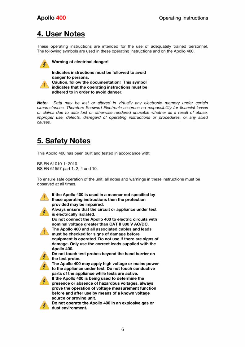
Apollo 400 Operating Instructions
6
4 User Notes
These operating instructions are intended for the use of adequately trained personnel The following symbols are used in these operating instructions and on the Apollo 400
Warning of electrical danger
Indicates instructions must be followed to avoid
danger to persons
Caution follow the documentation This symbol
indicates that the operating instructions must be
adhered to in order to avoid danger
Note Data may be lost or altered in virtually any electronic memory under certain
circumstances Therefore Seaward Electronic assumes no responsibility for financial losses
or claims due to data lost or otherwise rendered unusable whether as a result of abuse
improper use defects disregard of operating instructions or procedures or any allied
causes
5 Safety Notes
This Apollo 400 has been built and tested in accordance with BS EN 61010-1 2010 BS EN 61557 part 1 2 4 and 10 To ensure safe operation of the unit all notes and warnings in these instructions must be
observed at all times
If the Apollo 400 is used in a manner not specified by
these operating instructions then the protection
provided may be impaired
Always ensure that the circuit or appliance under test
is electrically isolated
Do not connect the Apollo 400 to electric circuits with
nominal voltage greater than CAT II 300 V ACDC
The Apollo 400 and all associated cables and leads
must be checked for signs of damage before
equipment is operated Do not use if there are signs of
damage Only use the correct leads supplied with the
Apollo 400
Do not touch test probes beyond the hand barrier on
the test probe
The Apollo 400 may apply high voltage or mains power
to the appliance under test Do not touch conductive
parts of the appliance while tests are active
If the Apollo 400 is being used to determine the
presence or absence of hazardous voltages always
prove the operation of voltage measurement function
before and after use by means of a known voltage
source or proving unit
Do not operate the Apollo 400 in an explosive gas or
dust environment
Apollo 400 Operating Instructions
7
The Apollo 400 has been designed to make
measurements in a dry environment
The Apollo 400 includes a rechargeable battery pack
which is charged while the Apollo 400 is connected to
a mains supply Only a Seaward battery pack should
be connected into the Apollo 400 Disconnect the
Apollo 400 from all leads before opening the battery
compartment
Do not open the Apollo 400 no user serviceable parts
Where safe operation of the Apollo 400 is no longer possible it should be immediately shut
down and secured to prevent accidental operation It must be assumed that safe operation is no longer possible - if the instrument or leads show visible signs of damage or - the instrument does not function or - after long periods of storage under adverse environmental conditions
6 Accessories
61 Standard Accessories
The Apollo 400 is supplied with the following items
Apollo 400 unit 1
Seaward black power lead 1
Test lead red 12m with alligator clip red 1
IEC test lead 1
USB Download Lead 1
62 Optional Accessories
Test lead red 12m with alligator clip black 380A983
Apollo Checkbox 380A953
Apollo carry case 380A952
Professional Seaward kit bag 71G109
Test n Tag Elite Bluetooth Label Printer 339A970
Test n Tag Pro Bluetooth Label Printer 339A980
Bluetooth Barcode Scanner 339A923
PATGuard 3 Software see wwwseawardcoukPG3Trial
110V test adaptor 270A076
3 Phase Leakage Adaptor 5 Star 16A 391A920
3 Phase Leakage Adaptor 5 Star 32A 391A910
3 Phase Adapter Delta 4 pin 16A 415V (for Rpe amp IR) 209A910
3 Phase Adapter Star 5 pin 16A 415V (for Rpe amp IR) 209A911
3 Phase Adapter Delta 4 pin 32A 415V (for Rpe amp IR) 209A912
3 Phase Adapter Star 5 pin 32A 415V (for Rpe amp IR) 209A913
Apollo 400 Operating Instructions
8
7 Introduction to the Apollo 400
Front
1 Test terminal end plate
2 Screen
3 Function keys F1 - F5
4 QWERTY keyboard
5 Power OffStop Key
6 Power OnStart Key
7 Arrow keys
Top
1 EUT test socket
2 IEC Inlet
3 Probe Socket
4 Mains InletProbe Socket 2
5 USB B Port for download
Back
1 Battery compartment
8 Getting Started
81 Charging New Batteries
Before using Apollo 400 for the first time please ensure that you fully charge the unit using
the Seaward black power lead plugged into the mains inlet socket on the top of the tester
82 Power On
This is the Power On button
This is the Power Off button
The first time the Apollo 400 is powered up the User will be automatically set to admin
For further information about changing User see 102 User Options
Apollo 400 Operating Instructions
9
9 User Interface Navigation
91 Screen Layout
1 Information bar
2 Function key icons
3 Test interface sequence table
4 Test interface details
5 Main area
Information Bar This area of the screen shows the Date Time Current User Battery Status and Connection
Status Function Key Icons This area of the screen is used to identify the current action assigned to the function keys Test Interface Sequence Table This area is only displaying in test mode showing the tests within the selected test sequence
This will also show the results and status of the results that have been performed In the
manual mode this table may only show one test Test Interface Details This area is only displayed in test mode showing the details specific to the active test This
includes the measurement an analogue measurement graph the duration and limit Some
tests may show more than more measurement Main Area This area is used to display menu items text fields and forms
92 Menu Navigation
The Apollo is controlled by the function keys The function key icons which are located
above each key are context sensitive and will change depending on the current options
available to you
This is the Home function This will take you back to the
Home screen
This is the Escape function This will return to the previous
screen without saving changes
This is the Accept function This will accept the changes
made in the current screen and move to the next screen
This is the Setup Options function This will take you the
Setup Options screen for the specific function that you are
currently viewing
This is the information key Depending on the current
screen displayed this will display the manual or the Apollo
400 details in the details screen this function will display
the manual
Apollo 400 Operating Instructions
10
This is the MenuOptions key This function will bring up a
context sensitive menu giving the options available for the
current screen
This is the Save key This function is used to save
datachanges that you have made on the current screen
93 Battery Status
While the Apollo 400 is powered on there are periodic checks of the batteries The Apollo
400 will show the status of the batteries
This symbol indicates that the batteries are at 100
capacity
There are several symbols which will display the current
battery voltage When these icons are displayed the
batteries are still good
This symbol indicates that the batteries are low
Although tests performed with the batteries in this state
are still valid all test types may not complete their
intended duration
This symbol indicates that the batteries are discharged
The Apollo 400 will switch itself off after a short period of
time
This symbol indicates that the Apollo 400 is bulk
charging batteries at the full charge current
This symbol indicates that the Apollo 400 is trickle
charging the batteries with reduced charge current This
is known as the Top Up Charge
This symbol indicates that the Apollo 400 has detected a
fault with the battery or battery charger circuit Unplug
the Apollo 400 from the mains supply and wait 2 minutes
before reconnecting the mains If the fault persists then
return the Apollo 400 for service Please note that the battery symbols are not updated in real time and may take a while to
update
94 Test Functionality
There are two buttons which control the starting and stopping of the selected test type
This is the Start Test button This is used to start
electrical tests
This is the Abort Test button This is used to stop
electrical tests
Apollo 400 Operating Instructions
11
10 Main Menu
101 View Saved Data This will allow you to view any data that you have saved in the Apollo 400 By selecting this
icon in the Main Menu you can view a list of all saved Asset IDs by site and location
Use the arrow keys to scroll up and down
This is the Accept function This will open the selected
record
This button allows you to filter records to give a
customised view Select the filters you wish to apply and
press lsquoAcceptrsquo
Once in the record you will be given a list of items under that record such as PAT results and
JPEG images Press Accept to open
This button allows you to delete the selectde record
When viewing a PAT_results record the Menu icon will become available so that you can
view results or print labels When viewing a saved Health amp Safety Form you can edit the report and then save the
changes This will create a new time and date stamped report as well as saving the original
This is the MenuOptions key This function will bring up a
context sensitive menu giving the options available for the
current screen
102 User Options
Apollo 400 has one default user account set up as admin who will have full access to the
product You can add one additional user account to the Apollo 400
This is where you can set up new edit and delete the user account The user can alter their
own screen power save time Auto power down background image avatar and power on
screen and press Save to apply
Use this button to Change User You can then select the
User name to change the current user of the tester
This User Information menu allows users to view their
user type (Expert or Novice)
This is the New User button Here you can set up a new
user account by adding a username and pressing lsquoSave
You can then select their name from the dropdown in the
User Information screen select the type of user (Expert or
Novice
Apollo 400 Operating Instructions
12
This is the Delete User button It will delete whichever
user is currently selected in the lsquoUsernamersquo dropdown
Please note that the admin user cannot be deleted
Press this button to Save changes and return to the
previous screen
103 Bluetooth Setup
Select this icon to setup your Bluetooth accessories to work with the Apollo 400 Switch on
the Bluetooth device you wish to pair with and ensure it is discoverable
This will Bluetooth Search button will search the area for
Bluetooth discoverable devices and return to the previous
menu You can then use the arrow keys to select the
correct Bluetooth ID from the dropdowns for your Bar
Code Scanner Printer or Mobile Device Press lsquoSaversquo
once complete
Press this button to save changes and return to the
previous screen
104 Automatic Test Sequence Editor (PAT Edit)
Although the Apollo 400 comes with a number of pre-defined test sequences you can modify
existing or create new test sequences of their own
From the Menu function key select one of the following options using the arrow keys and the
Accept button
This is the MenuOptions key This function will bring up a
context sensitive menu giving the options available for the
current screen
This is the Accept function This will open the selected
option
Edit Edits the highlighted sequence
Copy Makes a copy of the highlighted test
sequence
Delete Deletes the highlighted test sequence
Add New Adds a new test sequence to the bottom of the
list
Insert New Adds a new test below the highlighted test
sequence
Apollo 400 Operating Instructions
13
When editing a test sequence the following functions are available
This is the Add Test function This will add a new test
directly under the currently selected test
This is the Delete Test function This will delete the
highlighted test from the test sequence
This is the Edit Test function This will edit the
highlighted test
105 Download
Downloading to PATGuard 3
You can download the data from your Apollo to PATGuard 3 software
In the Download menu select To PATGuard in the Download from Apollo dropdown
This button is a way of downloading all data from Apollo
You then need to select one of 2 options from the using dropdown
USB-PC cable
Connect the USB download cable to the USB type B port on the Apollo 400 and to a USB
port on your PC Press Save
Instructions for how to import this download into PATGuard 3 can be found in the PATGuard
3 help files
Bluetooth to Mobile Device
You will need to have a Bluetooth enabled mobile device configured with the Apollo 400 to
use this method See 103 Bluetooth Setup
NB The Apollo 400 does not have the option to download to flash disk
106 Set Date and Time
You can change the date and time in this menu using the arrow keys and number keys
Press this button to save changes and return to the
previous screen
107 Memory
This section will allow you to view how much memory space you have used and how much
is left
This is the Restore button Selecting this will allow you to
clear memory or reset factory settings Select what you
Apollo 400 Operating Instructions
14
would like to restore by pressing the Enter button
Press this button to save changes and return to the
previous screen
11 Portable Appliance Testing
111 Automatic Test Sequence
The Apollo 400 comes with a number of pre-defined test sequences (see Factory Set Test
Sequences) These test sequences can include any combination of electrical tests These
test sequences are performed on equipment to ensure that it meets the safety requirements
outlined in the IET Code of Practice for In-service Inspection and Testing of Electrical
Equipment
1111 Entering Asset Details
Asset ID This is unique identifier for the equipment under
test This can be entered using the keypad or a
barcode scanner (see 103 Bluetooth Setup)
Test
Sequence This is the name of the pre-defined test sequence
which will be performed on the equipment
Site This is the site where the equipment is located
You can choose a site from the dropdown using
the arrow keys or enter a new one
Location This is the location within the site where the
equipment is You can choose a location from the
dropdown using the arrow keys or enter a new
one
Retest Period
(Visual) This is the period in months in which the
equipment should be re-inspected
Retest Period
(Full) This is the period in months in which the
equipment should be re-tested
1112 The Formal Visual Inspection
All pre-set test sequences start with a Visual Inspection
This is the Pass Icon
This is the Fail icon
Apollo 400 Operating Instructions
15
This means that the inspection is not applicable to the
EUT
Pass
All
Pressing the Pass All button will apply a pass to all
relevant inspections and move onto the next test
1113 The Electrical Tests
The Apollo 400 has probe detection that will automatically flag up if you do not have the
correct probe configuration for the test you are trying to perform
During the tests you can see the test duration limit and result on screen see 91 Screen
Layout
Should any test with the sequence fail the sequence will be aborted and you will presented
with the Notes screen by default but this can be changed see 115 PAT Settings
1114 Printing a Label
If you have a TnT Bluetooth printer configured with the Apollo 400 you can print a label after
each test
See 103 Bluetooth Settings to set up a printer
Press this button to go to the print screen and then
again to print a label
This is the Tools function This function allows you to
configure which pre-configured label printer to use
112 Manual Test Interface
The Apollo 400 allows direct access to all of the electrical tests through Manual Mode
Within each test there are a number of function key options
This is the Tools function This function allows you to
configure the test current test type this includes - test duration - test passfail limit
- test typeconnection
Always ensure that you have selected the correct test
connection method in the test for the probe
connections made
Please refer to the Test Functions section for specific information about each test type
Apollo 400 Operating Instructions
16
113 Test Functions
Earth Continuity
Always ensure that the circuit under test is electrically
isolated
Note that measurements can be adversely affected by
parallel resistances of additional circuits or by
transient currents
Connecting a test probe to a hazardous voltage when
a point to point measurement is active will result in
that voltage being present on the other test probe This test is applicable to Class I equipment This test will measure one of the following
resistance between the protective earth terminal in the EUT mains plug and the point
at which a single test probe is applied ndash CLI EUT Continuity
resistance between two test probes ndash Point to Point Continuity resistance between the protective earth terminal in an IEC lead mains plug and the
protective earth terminal in the IEC connector ndash IEC Continuity to ensure that the connection is satisfactory and of sufficiently low resistance The
measurement will be displayed in Ohms There are three possible connection methods for the Earth Continuity test
CLI EUT Continuity
The test is performed between the red
test terminal and the EUT test socket
Point to Point Continuity
This test is performed between the red
test terminal and the black test
terminal Additional test lead is
required
IEC Continuity
The test is performed between the EUT
test socket and the IEC test socket
Always ensure that you have selected the appropriate
test type for the probe connections
Apollo 400 Operating Instructions
17
Selecting test type
In manual PAT test mode the earth continuity test can be switched between a Class I EUT
continuity test and a point to point continuity test as follows
Select Class I Continuity (1) and press the setup key (F3) In the Test Type field select EUT
Continuity Test or Point to Point Continuity Test
During automatic sequences the test type will be as per the test type programmed in the
test sequence Once the correct connections have been made for the selected test type press
the Start button The test will continue until it times out If we wish to abort the current test
press the Stop button Tests on IEC leads CLI EUTs can be performed using a current of
+200mA andor -200mA Tests performed in point to point mode are always performed
using a current +200mA test The direction of the test current can be reversed by switching
the test probes at the point of connection to the appliancecircuit under test
Nulling out the earth continuity test lead(s) resistance
For a more accurate earth continuity measurement the resistance of the test lead(s) can be
zeroed out The feature can be used with both the EUT Continuity and Point to Point
measurement modes
The null facility remains active even if the Apollo 400 is powered off until the feature is
deactivated by pressing the null key again or the Test Type is changed eg if a pair of test
leads are nulled for point to point measurement the null will be deactivated if the Test Type
is changed to EUT Continuity test
Nulling a single test lead
In the manual PAT screen press the setup key (F3) and change the Test Type to EUT
Continuity Test Press save (F4) Connect the earth continuity test lead to the earth continuity
test socket and connect the probe tip to the earth pin of the EUT socket Press Null (F4) to
measure and stored the test lead resistance When the null feature is active the Null icon will
appear on the display
Nulling both test leads
In the manual PAT screen press the setup key (F3) and change the Test Type to Point to
Point Continuity Test Press save (F4) Connect both earth continuity test leads to the earth
continuity test sockets and connect the probe tips together using the supplied alligator clips
Press Null (F4) to measure and stored the test lead resistance When the null feature is active
the Null icon will appear on the display
Insulation Resistance
Always ensure that the circuit under test is electrically
isolated
Connecting a test probe to a hazardous voltage when
a point to point measurement is active will result in
that voltage being present on the other test probe This test is applicable to Class I and Class II equipment This test will measure one of the
following
insulation resistance between live circuits and the protective earth circuit in the EUT
ndash Class I IEC lead insulation test insulation resistance between live circuits and a test probe applied to the EUT ndash
Class II insulation test
Apollo 400 Operating Instructions
18
insulation resistance between two test probes ndash Point to Point Insulation
to ensure that the test points are adequately insulated from one another The measurement
is displayed in MOhms There are three possible connection methods for the Insulation test
CLI and IEC Insulation
The test is performed between the EUT
test socket live and neutral and the EUT
test socket earth pin For IEC leads the other end of the lead
should be connected into the IEC test
socket
CLII Insulation
The test is performed between the EUT
test socket live and neutral and Red
test terminal
Point to Point Insulation
The test is performed between the Red
and Black test terminals both the
continuity test leads are required for
this test Additional test lead is
required
Always ensure that you have selected the correct test
connection method in the test for the probe
connections made
Ensure that the appliance mains switch is in the ON
position
During this test 250V or 500V DC is applied between
the two connections points The 500V DC potential
will be present across the two probe tips during a
Point to Point test
Selecting test type
In manual PAT test mode the insulation test can be switched between a 250V EUT
Insulation test 500V EUT Insulation test 250V Point to Point Insulation test or 500V Point to
Point Insulation test as follows
Apollo 400 Operating Instructions
19
Select Insulation Resistance (2) and press the setup key (F3) In the Test Type field select
the required test
During automatic sequences the test type will be as per the test type programmed in the
test sequence
In manual mode once the correct connections have been made for the selected test type
press the Start button in automatic mode the test will proceed automatically The test will
continue until it times out If we wish to abort the current test press the Stop button The
measurement will be displayed in Mega Ohms If an EUT fails the Insulation test then this may be because of internal filtering or an MOV
Retry the test at 250V or substitute the Insulation test with a Protective Conductor or Touch
Current test
Substitute Leakage
This test is applicable to Class I and Class II equipment This test is used to verify that the
leakage between the mains conductors of the EUT to the EUT earth pin or conductive
accessible surface of the enclosure is to a satisfactory low level There are two possible connection methods for the Substitute Leakage test
CLI and IEC Substitute Leakage
The test is performed between the EUT
test socket live and neutral and the EUT
socket earth pin
For IEC leads the other end of the lead
should be connected into the IEC test
socket
CLII Substitute Leakage The test is performed between the EUT
socket live and neutral and Red test
terminal
During this test 40V AC is applied between the earth pin and both the live and neutral
pins of the appliance mains supply plug In manual mode once the correct connections have been made for the selected test type
press the Start button in automatic mode the test will proceed automatically The test will
continue until it times out If we wish to abort the current test press the Stop button The
measurement will be displayed in milli Amps
This test can prove useful in situations where neither conventional insulation nor flash tests
are acceptable methods of testing the insulation of the appliance
Please note that values for substitute leakage may differ substantially from that of
Apollo 400 Operating Instructions
20
conventional earth leakage tests because of the way that the test is performed (eg it will be
affected by the presence of Neutral-to-Earth suppression capacitors)
Protective Earth (PE) Conductor Current
Always test the earth continuity and insulation
resistance before performing a PE Conductor Current
test
Always check that an appliance with moving parts (eg
an electric drill) is safely mounted to avoid risk of
damage to equipment or personnel
Avoid prolonged repeated use at full load (16A) and
excessive test duration as this may reduce the life of the
unit
Always ensure that appliance and leads which include
RCD protection that the RCD is reset at the beginning
of the test Failure to do so may result in incorrect
measurements being recorded
This test is applicable on Class I
Equipment The Apollo 400 should be connected to
a mains supply The EUT should be
connected into the EUT test socket In manual mode once the correct
connections have been made for the
selected test type press
the Start button in automatic mode the
test will proceed automatically
The test will continue until it times out If we wish to abort the current test press
the Stop button The measurement will be displayed in mA Should the test measurement over range then the test will be aborted immediately and a fail
will be logged
Touch Current
Warning Always test the insulation resistance before
performing a Touch Current test
Warning Always check that an appliance with moving
parts (eg an electric drill) is safely mounted to avoid
risk of damage to equipment or personnel
Attention Avoid prolonged repeated use at full load
(16A) and excessive test duration as this may reduce the
life of the unit
Always ensure that appliance and leads which include
RCD protection that the RCD is reset at the beginning
of the test Failure to do so may result in incorrect
measurements being recorded
Apollo 400 Operating Instructions
21
This test is applicable on Class I and
Class II Equipment The Apollo 400 should be connected to
a mains supply The EUT should be
connected into the EUT socket the red
test terminal should be connected to
point at which the leakage measurement
is required
In manual mode once the correct connections have been made for the selected test type
press the Start button in automatic mode the test will proceed automatically The test will
continue until it times out If we wish to abort the current test press the Stop button The
measurement will be displayed in milli Amps Should the test measurement over range then the test will be aborted immediately and a fail
will be logged
RCD Trip Time
Voltages between the protective conductor and earth
may influence measurements This test will pass a sinusoidal current of 30mA between the EUT socket and the IEC socket
and measure the time it takes for the in-line RCD to trip
Remove all other connections before performing an
RCD test
The Apollo 400 should be connected to
a mains supply The RCD should be
plugged into the EUT test socket and a
connection should be made from the
RCD mains output to the IEC test
socket
Once the correct connections have been made for the selected test type press
the Start button The RCD will be powered and you will be prompted to reset the RCD
When you have reset the RCD the Apollo 400 will count down and then perform the RCD
test the RCD trip time will be displayed The measurement will be displayed in milli seconds
IEC Lead Polarity
The IEC lead input is a test socket and is not intended
to be connected directly to mains Do not connect this
input to the mains supply
The Polarity test checks the wiring
polarity of an IEC lead the IEC should
be plugged into both the EUT and IEC
test sockets
This test can be used to test the wiring polarity of extension leads by plugging the supplied
test IEC lead into the end of the extension lead to complete the circuit to the IEC tests
socket In the automatic sequence editor the Polarity can be added to sequence In the manual
mode the polarity test is already part of a pre-defined test sequence which includes an Earth
Continuity test an Insulation test and the Polarity test
External Leakage Adaptors
Apollo 400 Operating Instructions
22
While using an External Leakage Adaptor the mains
supply will be connected to the EUT through the
adaptor
Ensure that when tests are performed using the
external Leakage Adaptor that the Earth Reverse
option is set to Off
The External Leakage Adaptor test
function is intended to used in
conjunction with the one of Seawards
external leakage adaptors Connect the
external leakage adaptor into the Red
test terminal connect the Earth
Continuity probe into the Black test
terminal
Connect the mains supply and the EUT
to the external leakage adaptor
Note that connecting both the EUT and mains supply to the external leakage adaptor will
connect the mains supply to the EUT
114 Checkbox Verification
A checkbox for the Apollo 400 is available as an optional accessory This can be used to
verify that the Apollo 400 test functions are working correctly When selecting the Checkbox
function follow the onscreen instructions
The Checkbox function will perform a number of
electrical tests Ensure that the onscreen instructions
are followed and that you do not touch the checkbox
during the active tests
12 Updating your Firmware
1 Go to wwwseawardcoukfirmware and save the latest Apollo 400 firmware file on
your PC
2 Power on the unit whilst holding down the F1 button
3 Press F2 to update via PC
4 Follow the onscreen instructions
5 Restart the unit
You can check the firmware version of your tester by
pressing this icon in the Home screen
Apollo 400 Operating Instructions
23
13 Electrical Specification
Earth Continuity
Output Current (Load 2Ω)
Test Voltage (oc)
Measuring Range
Display Range
Resolution Operating Error
Number of tests as per IEC61557-
4
+- 200mA DC with ZAP
gt 4VDC
005 Ωndash 1999 Ω
001 Ω ndash 1999 Ω
001 Ω +-5 + 4 counts
approx 1500
Insulation Test
Test Voltages
Test Current
Test Voltage Accuracy
Measuring Range
Display Range
Resolution Operating Error ( lt 10MΩ ) ( gt 10MΩ )
Number of tests as per IEC61557-
2
500V and 250V DC
1mA minimum for a load of
1kohmvolt lt2mA into sc
+20 -0
010M Ω to 1999M Ω
000M Ω to 1999M Ω
001M Ω +-5 +5 counts +-10 +5 counts approx 1500
Subsitute Leakage Test
Test Voltages
Measuring Range
Display Range
Resolution Operating Error
gt25Vac lt50Vac
020mA to 1999mA
000mA to 1999mA
001mA +-10 +2 digits
Protective Conductor Current
Test Voltage
Display Range
Measurement Range
Resolution
Operating Error
Frequency Response
Supply Voltage maximum
load current 16A
001mA to 1999mA
025mA to 1999mA
001mA
+-5 of reading +- 3 digits
40Hz to 25 kHz
Touch Current
Test Voltage
Display Range
Measurement Range
Resolution
Operating Error
Frequency Response
Supply Voltage maximum
load current 16A
000mA to 350mA
010mA to 350mA
001mA
+-5 of reading +- 2 digits
DC to 25 kHz
Apollo 400 Operating Instructions
24
Load PowerCurrent
Test Voltage
Display Range
Measurement Range
Resolution
Operating Error
Supply Voltage maximum
load current 16A
000 - 1600A
050 - 1600A
001A
+-10 of reading +- 5 digits
Lead Test
Test Voltage
Test 5V DC nominal
Live Neutral checks for oc
sc and crossed
Power Socket Test
Input voltage range
195V ndash 253V AC
Indicates configuration of
voltage potential-
Line potential phase to earth
Line potential phase to neutral
Line potential neutral to earth
RCD Test
Test Voltage
Test Current
Test Current Accuracy
Display Range
Measuring Range
Resolution
Operating Error
230V +10 -15
30mA 150mA rms sinusoidal
30mA -10 +0 150mA +10 -0
0 ndash 2000ms
1ms ndash 2000ms
1ms plusmn1ms
External Leakage
Test Voltage
Display Range
Measuring Range
Resolution
Operating Error
Connected to External
Adapter
0mA - 999mA
025mA - 999mA
001mA +-5 of reading +-2 digits
Apollo 400 Operating Instructions
25
14 Useful Information - 141 Factory Set Test Sequences
Test
Visual Earth Continuity Insulation PE Conductor
Current Touch Current
Substitute
Leakage Wiring
RCD
Trip
Time
Name
Duration
(s)
Limit
(ΩΩ) Duration (s) Voltage
Limit
(MΩΩ)
Duration
(s)
Limit
(mA)
Duration
(s)
Limit
(mA)
Duration
(s)
Limit
(mA)
Limit
(ms)
PortableHandheldIT CLI Yes 5 01 2 500 1
PortableHandheldIT CLII Yes 2 500 2
Fixed Appliance CLI Yes 2 01 5 500 1
Fixed Appliance CLII Yes 5 500 2
IEC Lead 2m Yes 5 02 2 500 1 Yes
13A 5m Surge Protected Lead Yes 5 02 2 250 1 Yes
13A 25m Ext Lead 30mA RCD Yes 5 05 5 08 30
Portable CLI PE Current Yes 5 05 2 250 1 5 08
Portable CLII Touch Current Yes 2 250 2 5 03
IT Equip CLI PE Current Yes 5 01 2 250 1 5 35
IT Equip CLII T ouch Current Yes 2 250 5 03
13A 6m Mains Lead Yes 5 02 2 500 1 Yes
13A 12m Mains Lead Yes 5 03 2 500 1 Yes
13A 24m Mains Lead Yes 5 05 2 500 1 Yes
MovStat CLI 500V Insulation Yes 5 01 2 500 1
MovStat CLII 500V Insulation Yes 2 500 2
MovStat CLI PE Current Yes 5 01 2 250 1 5 35
MovStat CLII Touch Current Yes 2 250 2 5 35
110V HandheldPortable CLI Yes 5 01 2 500 1 2 08
110V HandheldPortable CLII Yes 2 500 2 2 03
110V MovableStationary CLI Yes 5 01 2 500 1 2 35
110V MovableStationary CLII Yes 2 500 2 2 03
110V 25m Lead
RpeampInsulation Yes 5 05 2 500 1
Visual Only Yes
Apollo 400 Operating Instructions
26
142 Other Information
Parameter Default Min Max
Earth Continuity PF limit (Ω) 01 001 1999
Earth Continuity Duration (s) 5 2 30
Insulation Resistance PF limit (MΩ) 1 001 1999
Insulation Resistance Duration (s) 5 2 30
Substitute Leakage PF limit (mA) 075 025 15
Substitute Leakage Duration (s) 5 2 30
IEC Cord Earth Continuity PF limit
(ohms) 01 001 5
IEC Cord Insulation PF limit (MΩ) 1 001 1999
Touch Current PF limit (mA) 025 025 350
Touch Current Duration (s) 5 2 30
PE Conductor Current PF limit (mA) 075 025 1999
PE Conductor Current Duration (s) 5 2 30
External Adapter Continuity (Ω) 01 001 5
External Adapter Leakage (mA) 075 025 999
External Adapter Duration (s) 5 2 30
RCD 30mA trip time (ms) 200 1 2000
RCD 150mA trip time (ms) 40 1 40
Number of tests in a test sequence 1 60
Characters in a test sequence name 1 30
Characters in a User Test name 1 15
Characters in a User Test Unit 15
Total number of Test Sequences 25
Test Results (typical) 2000
Sites 50
Characters in Site name 1 15
Locations 50
Characters in Location name 1 15
Users (including admin) 2
Characters in User name 1 15
Comments List 50
Characters in Comment 25
Characters in Asset ID 1 15
Apollo 400 Operating Instructions
27
15 Environmental Conditions
The Apollo 400 has been designed to perform tests and measurements in a dry environment
Maximum barometric elevation for making measurements is 2000M
Pollution degree 2 according to IEC 60529
Electromagnetic compatibility (EMC) Interference immunity and emitted interference
conforming to IEC 61326-1
Operating temperature range of 0 to 40 degrees C without moisture condensation
Operating Altitude 0 to 2000 metres
16 Maintenance
161 Charging the battery pack
The battery pack will be charged whenever the Apollo 400 is connected to the mains supply
regardless of whether it is switched on or off
The typical charging current is set to 500mA but this may vary as the instrument also
includes pre-charge and top up charge modes
When no tests are being performed the battery pack will be fully re-charged after 7 hours
162 Securing the Apollo 400
Under certain conditions safe operation of the Apollo 400 can no longer be assumed
Visible damage of the instrument case
Incorrect measurement results
Recognisable abuse to the instrument due to prolonged storage under improper conditions
Recognisable abuse to the instrument due to extraordinary transportation stress
In these case the Apollo 400 should be immediately switched off disconnected from any test
and measurement function and secured to prevent any further use
163 Cleaning the Apollo 400
Clean the external case of the Apollo 400 with a dry clean cloth
Avoid using solvents and abrasive scouring agents to clean the external case of the Apollo
400
Apollo 400 Operating Instructions
28
164 Replacing the battery pack
Before opening the Apollo 400 battery compartment
ensure that all test leads and accessories are
disconnected
Power off the instrument
Disconnect all test leads and accessories
Position the instrument face down and remove the screw holding the battery compartment
cover in place
Remove the battery compartment cover
Remove the battery pack from the compartment and unplug the 4 way connector
Connect the 4 way connector of the new battery to the 4 way header in the battery
compartment put the battery pack into the compartment
Relocate the battery compartment cover and fasten in position with the battery compartment
screw
ONLY USE A REPLACEMENT BATTERY PACK THAT HAS BEEN SUPPLIED BY SEAWARD
OR A SEAWARD APPROVED DISTRIBUTOR
17 Support
The Apollo 400 must be registered with Seaward before support will be made available For Technical Support contact Tel (+44) 191 587 8718
For help or advice on Service and Calibration contact
CalibrationHouse Seaward Electronic Bracken Hill South West Industrial Estate Peterlee Co Durham SR8 2SW England Tel (+44) 191 5878739 (+44) 191 5878737 Email serviceseawardcouk
Calibration House is part of the Seaward Group
Apollo 400 Operating Instructions
29
171 Register your product here-
wwwseawardcouk 172 Calibration Services-
wwwcalibrationhousecouk Bracken Hill South West Industrial Estate Peterlee County Durham SR8 2SW Co Durham SR8 2SW England Tel (+44) 191 5863511 Some icons provided by Fat Cow (httpwwwfatcowcomfree-icons) Based in part on the work of the Qwt project (httpqwtsfnet)
Apollo 400A simple no-nonsense PAT tester with fast data entry and storage for up to 2000appliance records
Key Featuresn High definition colour displayn Store 2000 appliance recordsn Remote data transfer from field to office n Bluetooth connectivity
Electrical Test Functionsn Low current earth continuity test guaranteeing accurate measurement n Point to point testing (earth continuity and insulation resistance)n Insulation resistancen IEC lead testn Protective conductor currentn Touch currentn Load powercurrentn Alternative leakage currentn RCD testn Power socket test
Ideal Forn Electrical Contractorsn Facilities Managersn Operations Managers
Apollo 400 offers simple electrical safety testing with straightforward data entryusing the intuitive QWERTY keypad
A comprehensive range of electrical safety tests ensure compliance with theIET 4th Edition Code of Practice whilst remote data transfer and USB downloadmakes data management easy and efficient
The Apollo 400 is ideal for mid-volume PAT testing where detailed records arerequired
Streamline the PAT testing process further by using the Apollo 400 with acompatible label printer barcode scanner and PATGuard 3 software
wwwseawardcoukapollo400
Tel +44 (0) 191 587 8741Email salesseawardcouk
Requires optional accessory (part number 380A983)
Straightforward PAT testing with simple data managementApollo 400 offers a comprehensive suite of electrical safetytests to enable any workplace appliance to be tested including3-phase equipment fixed appliances and RCDs
The QWERTY keypad enables asset information to be entered quicklyand easily while a large colour display with an intuitive menu structure makesthe Apollo 400 simple to grasp Lightweight and small in size with battery or mainspower modes the Apollo 400 is good to go in seconds allowing more appliances to betested without downtime for boot-up or a battery re-charge
Superb software for total traceabilityApollo 400 has an internal memory capable of storing up to 2000electrical test records Its compatibility with Seawardrsquos PATGuard 3software means that complete test records are easily managed ona PC
Transfer data to the PC remotely using the Bluetooth function anda smartphone or download the results via a USB cable directly toa PC Once downloaded to PATGuard 3 it is easy to keep track ofthe history of test and inspections as well as produce reportscertificates and invoices ndash offering total peace of mind and quickereasier management of scheduling inspections and tests
Download a free trial at wwwseawardcoukpg3trial
wwwseawardcoukapollo400
Tel +44 (0) 191 587 8741Email salesseawardcouk
additional accessory required for point to point testing
u Accessory BundlesThe Apollo 400 is available to buy with a selectionof optional accessory bundles to help you get themost out of your tester
Apollo 400 is supplied as standard with a UKAScalibration certificate and a 2 yearmanufacturerrsquos warranty (subject to terms andconditions)
Greater efficiency through useful accessoriesAs with many Seaward PAT testers the Apollo 400 is compatible with arange of printers and barcode scanners further speeding up the processof asset recognition testing and labelling
Also available in this range
A multi-tasking and fully customisable PAT with additionalhealth and safety features and on-board camera forunrivalled record keeping
Apollo 600 includes a universal risk assessment tool andthe ability to store up to 50000 appliance records plus2000 images - providing visual evidence of testenvironments perfect for advanced record-keeping inorganisations with high-volume workplace test andinspection routines
Apollo 600Multi-tasking PAT tester with on-board camera
wwwseawardcoukapollo400
Tel +44 (0) 191 587 8741Email salesseawardcouk
A powerful PAT tester with a built-in PAT retest calculatorand flexible user-configurable sequences for recordingany non-electrical workplace test or inspection
The ability to customise a number of settings and a largememory to store up to 10000 appliance records makesthe Apollo 500 a versatile and dependable tool for highvolume PAT testing
Apollo 500A fast amp fully customisable and versatile PAT tester
Optional accessory bundles available Part Number
Elite Bundle n Test n Tag Elite 2 rugged portable printer
n Test n Tag printer labels x 4
n Bluetooth barcode scanner
n Apollo kit carry case
n 110V adapter
Includes Apollo 400 tester
380A978
Elite Bundle +Software
PLUS PATGuard 3 software 1yr licence 380A979
Pro Bundle n Test n Tag Pro lightweight portable printer
n Test n Tag printer labels x 4
n Bluetooth barcode scanner
n Apollo kit carry case
n 110V adapter
Includes Apollo 400 tester
380A980
Pro Bundle +Software PLUS PATGuard 3 software 1yr licence 380A981
wwwseawardcoukapollo400
Tel +44 (0) 191 587 8741Email salesseawardcouk
Apollo 400 Apollo 500 Apollo 600
General Features
Battery amp mains powered n n n
Colour Screen amp QWERTY keypad n n n
Large internal memory 2000 records 10000 records 50000 records
Scanner amp printer compatible n n n
Password controlled user accounts n n
Set up multiple user accounts with varyinglevels of privileges
n n
Clone facility to set up multiple testers n n
Checkbox supplied as standard n n
On-board user manual n n
Test amp InspectionFeatures
Auto-increment asset ID n n
PAT Setup option to allow for custom menus n n
Enter asset description after test usingkeypad or barcode scanner
n n n
Comprehensive electrical safety test features n n n
Point to point measurement (Rpe amp IR)
n
(optional
accessory
required)
n n
User configurable electrical testvisualinspection sequences 25 100 100
User set sites amp locations 50 100 100
Risk based retest period calculator n n
User definable comments lines against testrecords
n n
Configurable checklists for any workplacetest or inspection (user tests)
n n
On-board camera n
Universal risk assessment n
Health amp safety certificates n
Data Transfer
Bluetooth connectivity n n n
Barcode scanner connectivity n n n
Print Pass amp Fail labels n n n
Add your company logo to labels n n
Select from various label formats to print n n
Remote data transfer via mobile device n
(Android only)
n
(Android only)
n
(Android and iOS)
Download to PC via USB cable n n n
Filter results to be downloaded n n
Upload previous results to tester for retest n n
Data transfer via USB flash drive n
Apollo Series Comparison Chart
PAT TESTS
Earth ContinuityTest Current +- 200mA DC Display Range 001 ndash 1999ΩPass Value User Defined
Insulation ResistanceTest Voltage 500V 250VDC 1mA nominalDisplay Range 001MΩ - 1999MΩPass Value User Defined
IEC Lead TestTest Voltage 5VAC nominalTest Live Neutral Checks for oc sc and crossed
Protective Conductor CurrentLoad
Test Voltage Supply voltage maximum load current 16A Display Ranges 001mA to 1999mA Pass Value User Defined
Touch Current
Test Voltage Supply Voltage maximum load current 16ADisplay Range 000 ndash 350mA Pass Value User defined
Load PowerCurrent
Test Voltage Supply Voltage maximum load current 16ATest Duration Programmable up to a maximum of 255s depending on load ie max duration is reduced for high loadsDisplay Range 000kVA ndash 400kVA 000A ndash 1600A
Alternative Leakage Current
Test Voltages gt25VAC lt50VAC Display Range 000mA to 1999mAPass Value User Defined
RCD Test
Test Voltage 230V +10 -15Test Current 30mA 150mA rms sinusoidalDisplay Range 0ms - 2000ms (30mA) 0-40ms (150mA)Test Method Internal isolation to avoid tripping distribution board RCD
Power Socket Test
Voltage Range 207V ndash 253VACIndicates configuration of voltage potential-Line potential phase to earthLine potential phase to neutralLine potential neutral to earth
General
Memory Size 2000 recordsWeight 15kgDimensions 230mm x 150mm x 100mmPower Source Mains or rechargeable battery pack
Standard Accessories (supplied with Apollo 400)30 day free trial of PATGuard 3 software 1x red test lead and probe with crocodile clip05m IEC leadMains power leadUSB download cableQuick start guideUKAS calibration certificate
Optional Accessories Test n Tag Elite 2 Bluetooth printer with roll of small labels (339A995)Test n Tag Pro Bluetooth printer with roll of small labels (339A987)Roll of small labels (approx 350 off 52 x 25mm labels) (339A947)Additional black test lead and probe with crocodile clip (for point to point testing) (380A983)Bluetooth barcode scanner (339A923)110V test adaptor (270A076)110V to IEC adapter (344A050)Apollo checkbox (380A953)3 Phase Leakage Adaptor 5 Star 16A (391A920)3 Phase Leakage Adaptor 5 Star 32A (391A910)3 Phase Adapter Delta 4 pin 16A 415V (for Rpe amp IR) (209A910)3 Phase Adapter Star 5 pin 16A 415V (for Rpe amp IR) (209A911)3 Phase Adapter Delta 4 pin 32A 415V (for Rpe amp IR) (209A912)3 Phase Adapter Star 5 pin 32A 415V (for Rpe amp IR) (209A913)Professional Seaward kit bag (71G109)Apollo carry case (380A952)PATGuard 3 software ndash download 30 day free trial atwwwseawardcoukpg3trial
Part NumbersApollo 400 standard package 380A920Apollo 400 with Elite accessory bundle 380A978Apollo 400 with Elite accessory bundle amp PATGuard 3 one year licence380A979Apollo 400 with Pro accessory bundle 380A980Apollo 400 with Pro accessory bundle amp PATGuard 3 one year licence380A981
TrainingSeaward offer a range of PAT testing courses including City amp GuildsGo to wwwseawardcouktraining for more information
Services2 year warranty (subject to terms and conditions available atwwwseawardcoukwarranty24)Service amp Calibration by CalibrationhouseGo to wwwcalibrationhousecom for more information
Technical Specifications
Part of
Rev 12
wwwseawardcoukapollo400
Tel +44 (0) 191 587 8741Email salesseawardcouk
Apollo 400 Operating Instructions
7
The Apollo 400 has been designed to make
measurements in a dry environment
The Apollo 400 includes a rechargeable battery pack
which is charged while the Apollo 400 is connected to
a mains supply Only a Seaward battery pack should
be connected into the Apollo 400 Disconnect the
Apollo 400 from all leads before opening the battery
compartment
Do not open the Apollo 400 no user serviceable parts
Where safe operation of the Apollo 400 is no longer possible it should be immediately shut
down and secured to prevent accidental operation It must be assumed that safe operation is no longer possible - if the instrument or leads show visible signs of damage or - the instrument does not function or - after long periods of storage under adverse environmental conditions
6 Accessories
61 Standard Accessories
The Apollo 400 is supplied with the following items
Apollo 400 unit 1
Seaward black power lead 1
Test lead red 12m with alligator clip red 1
IEC test lead 1
USB Download Lead 1
62 Optional Accessories
Test lead red 12m with alligator clip black 380A983
Apollo Checkbox 380A953
Apollo carry case 380A952
Professional Seaward kit bag 71G109
Test n Tag Elite Bluetooth Label Printer 339A970
Test n Tag Pro Bluetooth Label Printer 339A980
Bluetooth Barcode Scanner 339A923
PATGuard 3 Software see wwwseawardcoukPG3Trial
110V test adaptor 270A076
3 Phase Leakage Adaptor 5 Star 16A 391A920
3 Phase Leakage Adaptor 5 Star 32A 391A910
3 Phase Adapter Delta 4 pin 16A 415V (for Rpe amp IR) 209A910
3 Phase Adapter Star 5 pin 16A 415V (for Rpe amp IR) 209A911
3 Phase Adapter Delta 4 pin 32A 415V (for Rpe amp IR) 209A912
3 Phase Adapter Star 5 pin 32A 415V (for Rpe amp IR) 209A913
Apollo 400 Operating Instructions
8
7 Introduction to the Apollo 400
Front
1 Test terminal end plate
2 Screen
3 Function keys F1 - F5
4 QWERTY keyboard
5 Power OffStop Key
6 Power OnStart Key
7 Arrow keys
Top
1 EUT test socket
2 IEC Inlet
3 Probe Socket
4 Mains InletProbe Socket 2
5 USB B Port for download
Back
1 Battery compartment
8 Getting Started
81 Charging New Batteries
Before using Apollo 400 for the first time please ensure that you fully charge the unit using
the Seaward black power lead plugged into the mains inlet socket on the top of the tester
82 Power On
This is the Power On button
This is the Power Off button
The first time the Apollo 400 is powered up the User will be automatically set to admin
For further information about changing User see 102 User Options
Apollo 400 Operating Instructions
9
9 User Interface Navigation
91 Screen Layout
1 Information bar
2 Function key icons
3 Test interface sequence table
4 Test interface details
5 Main area
Information Bar This area of the screen shows the Date Time Current User Battery Status and Connection
Status Function Key Icons This area of the screen is used to identify the current action assigned to the function keys Test Interface Sequence Table This area is only displaying in test mode showing the tests within the selected test sequence
This will also show the results and status of the results that have been performed In the
manual mode this table may only show one test Test Interface Details This area is only displayed in test mode showing the details specific to the active test This
includes the measurement an analogue measurement graph the duration and limit Some
tests may show more than more measurement Main Area This area is used to display menu items text fields and forms
92 Menu Navigation
The Apollo is controlled by the function keys The function key icons which are located
above each key are context sensitive and will change depending on the current options
available to you
This is the Home function This will take you back to the
Home screen
This is the Escape function This will return to the previous
screen without saving changes
This is the Accept function This will accept the changes
made in the current screen and move to the next screen
This is the Setup Options function This will take you the
Setup Options screen for the specific function that you are
currently viewing
This is the information key Depending on the current
screen displayed this will display the manual or the Apollo
400 details in the details screen this function will display
the manual
Apollo 400 Operating Instructions
10
This is the MenuOptions key This function will bring up a
context sensitive menu giving the options available for the
current screen
This is the Save key This function is used to save
datachanges that you have made on the current screen
93 Battery Status
While the Apollo 400 is powered on there are periodic checks of the batteries The Apollo
400 will show the status of the batteries
This symbol indicates that the batteries are at 100
capacity
There are several symbols which will display the current
battery voltage When these icons are displayed the
batteries are still good
This symbol indicates that the batteries are low
Although tests performed with the batteries in this state
are still valid all test types may not complete their
intended duration
This symbol indicates that the batteries are discharged
The Apollo 400 will switch itself off after a short period of
time
This symbol indicates that the Apollo 400 is bulk
charging batteries at the full charge current
This symbol indicates that the Apollo 400 is trickle
charging the batteries with reduced charge current This
is known as the Top Up Charge
This symbol indicates that the Apollo 400 has detected a
fault with the battery or battery charger circuit Unplug
the Apollo 400 from the mains supply and wait 2 minutes
before reconnecting the mains If the fault persists then
return the Apollo 400 for service Please note that the battery symbols are not updated in real time and may take a while to
update
94 Test Functionality
There are two buttons which control the starting and stopping of the selected test type
This is the Start Test button This is used to start
electrical tests
This is the Abort Test button This is used to stop
electrical tests
Apollo 400 Operating Instructions
11
10 Main Menu
101 View Saved Data This will allow you to view any data that you have saved in the Apollo 400 By selecting this
icon in the Main Menu you can view a list of all saved Asset IDs by site and location
Use the arrow keys to scroll up and down
This is the Accept function This will open the selected
record
This button allows you to filter records to give a
customised view Select the filters you wish to apply and
press lsquoAcceptrsquo
Once in the record you will be given a list of items under that record such as PAT results and
JPEG images Press Accept to open
This button allows you to delete the selectde record
When viewing a PAT_results record the Menu icon will become available so that you can
view results or print labels When viewing a saved Health amp Safety Form you can edit the report and then save the
changes This will create a new time and date stamped report as well as saving the original
This is the MenuOptions key This function will bring up a
context sensitive menu giving the options available for the
current screen
102 User Options
Apollo 400 has one default user account set up as admin who will have full access to the
product You can add one additional user account to the Apollo 400
This is where you can set up new edit and delete the user account The user can alter their
own screen power save time Auto power down background image avatar and power on
screen and press Save to apply
Use this button to Change User You can then select the
User name to change the current user of the tester
This User Information menu allows users to view their
user type (Expert or Novice)
This is the New User button Here you can set up a new
user account by adding a username and pressing lsquoSave
You can then select their name from the dropdown in the
User Information screen select the type of user (Expert or
Novice
Apollo 400 Operating Instructions
12
This is the Delete User button It will delete whichever
user is currently selected in the lsquoUsernamersquo dropdown
Please note that the admin user cannot be deleted
Press this button to Save changes and return to the
previous screen
103 Bluetooth Setup
Select this icon to setup your Bluetooth accessories to work with the Apollo 400 Switch on
the Bluetooth device you wish to pair with and ensure it is discoverable
This will Bluetooth Search button will search the area for
Bluetooth discoverable devices and return to the previous
menu You can then use the arrow keys to select the
correct Bluetooth ID from the dropdowns for your Bar
Code Scanner Printer or Mobile Device Press lsquoSaversquo
once complete
Press this button to save changes and return to the
previous screen
104 Automatic Test Sequence Editor (PAT Edit)
Although the Apollo 400 comes with a number of pre-defined test sequences you can modify
existing or create new test sequences of their own
From the Menu function key select one of the following options using the arrow keys and the
Accept button
This is the MenuOptions key This function will bring up a
context sensitive menu giving the options available for the
current screen
This is the Accept function This will open the selected
option
Edit Edits the highlighted sequence
Copy Makes a copy of the highlighted test
sequence
Delete Deletes the highlighted test sequence
Add New Adds a new test sequence to the bottom of the
list
Insert New Adds a new test below the highlighted test
sequence
Apollo 400 Operating Instructions
13
When editing a test sequence the following functions are available
This is the Add Test function This will add a new test
directly under the currently selected test
This is the Delete Test function This will delete the
highlighted test from the test sequence
This is the Edit Test function This will edit the
highlighted test
105 Download
Downloading to PATGuard 3
You can download the data from your Apollo to PATGuard 3 software
In the Download menu select To PATGuard in the Download from Apollo dropdown
This button is a way of downloading all data from Apollo
You then need to select one of 2 options from the using dropdown
USB-PC cable
Connect the USB download cable to the USB type B port on the Apollo 400 and to a USB
port on your PC Press Save
Instructions for how to import this download into PATGuard 3 can be found in the PATGuard
3 help files
Bluetooth to Mobile Device
You will need to have a Bluetooth enabled mobile device configured with the Apollo 400 to
use this method See 103 Bluetooth Setup
NB The Apollo 400 does not have the option to download to flash disk
106 Set Date and Time
You can change the date and time in this menu using the arrow keys and number keys
Press this button to save changes and return to the
previous screen
107 Memory
This section will allow you to view how much memory space you have used and how much
is left
This is the Restore button Selecting this will allow you to
clear memory or reset factory settings Select what you
Apollo 400 Operating Instructions
14
would like to restore by pressing the Enter button
Press this button to save changes and return to the
previous screen
11 Portable Appliance Testing
111 Automatic Test Sequence
The Apollo 400 comes with a number of pre-defined test sequences (see Factory Set Test
Sequences) These test sequences can include any combination of electrical tests These
test sequences are performed on equipment to ensure that it meets the safety requirements
outlined in the IET Code of Practice for In-service Inspection and Testing of Electrical
Equipment
1111 Entering Asset Details
Asset ID This is unique identifier for the equipment under
test This can be entered using the keypad or a
barcode scanner (see 103 Bluetooth Setup)
Test
Sequence This is the name of the pre-defined test sequence
which will be performed on the equipment
Site This is the site where the equipment is located
You can choose a site from the dropdown using
the arrow keys or enter a new one
Location This is the location within the site where the
equipment is You can choose a location from the
dropdown using the arrow keys or enter a new
one
Retest Period
(Visual) This is the period in months in which the
equipment should be re-inspected
Retest Period
(Full) This is the period in months in which the
equipment should be re-tested
1112 The Formal Visual Inspection
All pre-set test sequences start with a Visual Inspection
This is the Pass Icon
This is the Fail icon
Apollo 400 Operating Instructions
15
This means that the inspection is not applicable to the
EUT
Pass
All
Pressing the Pass All button will apply a pass to all
relevant inspections and move onto the next test
1113 The Electrical Tests
The Apollo 400 has probe detection that will automatically flag up if you do not have the
correct probe configuration for the test you are trying to perform
During the tests you can see the test duration limit and result on screen see 91 Screen
Layout
Should any test with the sequence fail the sequence will be aborted and you will presented
with the Notes screen by default but this can be changed see 115 PAT Settings
1114 Printing a Label
If you have a TnT Bluetooth printer configured with the Apollo 400 you can print a label after
each test
See 103 Bluetooth Settings to set up a printer
Press this button to go to the print screen and then
again to print a label
This is the Tools function This function allows you to
configure which pre-configured label printer to use
112 Manual Test Interface
The Apollo 400 allows direct access to all of the electrical tests through Manual Mode
Within each test there are a number of function key options
This is the Tools function This function allows you to
configure the test current test type this includes - test duration - test passfail limit
- test typeconnection
Always ensure that you have selected the correct test
connection method in the test for the probe
connections made
Please refer to the Test Functions section for specific information about each test type
Apollo 400 Operating Instructions
16
113 Test Functions
Earth Continuity
Always ensure that the circuit under test is electrically
isolated
Note that measurements can be adversely affected by
parallel resistances of additional circuits or by
transient currents
Connecting a test probe to a hazardous voltage when
a point to point measurement is active will result in
that voltage being present on the other test probe This test is applicable to Class I equipment This test will measure one of the following
resistance between the protective earth terminal in the EUT mains plug and the point
at which a single test probe is applied ndash CLI EUT Continuity
resistance between two test probes ndash Point to Point Continuity resistance between the protective earth terminal in an IEC lead mains plug and the
protective earth terminal in the IEC connector ndash IEC Continuity to ensure that the connection is satisfactory and of sufficiently low resistance The
measurement will be displayed in Ohms There are three possible connection methods for the Earth Continuity test
CLI EUT Continuity
The test is performed between the red
test terminal and the EUT test socket
Point to Point Continuity
This test is performed between the red
test terminal and the black test
terminal Additional test lead is
required
IEC Continuity
The test is performed between the EUT
test socket and the IEC test socket
Always ensure that you have selected the appropriate
test type for the probe connections
Apollo 400 Operating Instructions
17
Selecting test type
In manual PAT test mode the earth continuity test can be switched between a Class I EUT
continuity test and a point to point continuity test as follows
Select Class I Continuity (1) and press the setup key (F3) In the Test Type field select EUT
Continuity Test or Point to Point Continuity Test
During automatic sequences the test type will be as per the test type programmed in the
test sequence Once the correct connections have been made for the selected test type press
the Start button The test will continue until it times out If we wish to abort the current test
press the Stop button Tests on IEC leads CLI EUTs can be performed using a current of
+200mA andor -200mA Tests performed in point to point mode are always performed
using a current +200mA test The direction of the test current can be reversed by switching
the test probes at the point of connection to the appliancecircuit under test
Nulling out the earth continuity test lead(s) resistance
For a more accurate earth continuity measurement the resistance of the test lead(s) can be
zeroed out The feature can be used with both the EUT Continuity and Point to Point
measurement modes
The null facility remains active even if the Apollo 400 is powered off until the feature is
deactivated by pressing the null key again or the Test Type is changed eg if a pair of test
leads are nulled for point to point measurement the null will be deactivated if the Test Type
is changed to EUT Continuity test
Nulling a single test lead
In the manual PAT screen press the setup key (F3) and change the Test Type to EUT
Continuity Test Press save (F4) Connect the earth continuity test lead to the earth continuity
test socket and connect the probe tip to the earth pin of the EUT socket Press Null (F4) to
measure and stored the test lead resistance When the null feature is active the Null icon will
appear on the display
Nulling both test leads
In the manual PAT screen press the setup key (F3) and change the Test Type to Point to
Point Continuity Test Press save (F4) Connect both earth continuity test leads to the earth
continuity test sockets and connect the probe tips together using the supplied alligator clips
Press Null (F4) to measure and stored the test lead resistance When the null feature is active
the Null icon will appear on the display
Insulation Resistance
Always ensure that the circuit under test is electrically
isolated
Connecting a test probe to a hazardous voltage when
a point to point measurement is active will result in
that voltage being present on the other test probe This test is applicable to Class I and Class II equipment This test will measure one of the
following
insulation resistance between live circuits and the protective earth circuit in the EUT
ndash Class I IEC lead insulation test insulation resistance between live circuits and a test probe applied to the EUT ndash
Class II insulation test
Apollo 400 Operating Instructions
18
insulation resistance between two test probes ndash Point to Point Insulation
to ensure that the test points are adequately insulated from one another The measurement
is displayed in MOhms There are three possible connection methods for the Insulation test
CLI and IEC Insulation
The test is performed between the EUT
test socket live and neutral and the EUT
test socket earth pin For IEC leads the other end of the lead
should be connected into the IEC test
socket
CLII Insulation
The test is performed between the EUT
test socket live and neutral and Red
test terminal
Point to Point Insulation
The test is performed between the Red
and Black test terminals both the
continuity test leads are required for
this test Additional test lead is
required
Always ensure that you have selected the correct test
connection method in the test for the probe
connections made
Ensure that the appliance mains switch is in the ON
position
During this test 250V or 500V DC is applied between
the two connections points The 500V DC potential
will be present across the two probe tips during a
Point to Point test
Selecting test type
In manual PAT test mode the insulation test can be switched between a 250V EUT
Insulation test 500V EUT Insulation test 250V Point to Point Insulation test or 500V Point to
Point Insulation test as follows
Apollo 400 Operating Instructions
19
Select Insulation Resistance (2) and press the setup key (F3) In the Test Type field select
the required test
During automatic sequences the test type will be as per the test type programmed in the
test sequence
In manual mode once the correct connections have been made for the selected test type
press the Start button in automatic mode the test will proceed automatically The test will
continue until it times out If we wish to abort the current test press the Stop button The
measurement will be displayed in Mega Ohms If an EUT fails the Insulation test then this may be because of internal filtering or an MOV
Retry the test at 250V or substitute the Insulation test with a Protective Conductor or Touch
Current test
Substitute Leakage
This test is applicable to Class I and Class II equipment This test is used to verify that the
leakage between the mains conductors of the EUT to the EUT earth pin or conductive
accessible surface of the enclosure is to a satisfactory low level There are two possible connection methods for the Substitute Leakage test
CLI and IEC Substitute Leakage
The test is performed between the EUT
test socket live and neutral and the EUT
socket earth pin
For IEC leads the other end of the lead
should be connected into the IEC test
socket
CLII Substitute Leakage The test is performed between the EUT
socket live and neutral and Red test
terminal
During this test 40V AC is applied between the earth pin and both the live and neutral
pins of the appliance mains supply plug In manual mode once the correct connections have been made for the selected test type
press the Start button in automatic mode the test will proceed automatically The test will
continue until it times out If we wish to abort the current test press the Stop button The
measurement will be displayed in milli Amps
This test can prove useful in situations where neither conventional insulation nor flash tests
are acceptable methods of testing the insulation of the appliance
Please note that values for substitute leakage may differ substantially from that of
Apollo 400 Operating Instructions
20
conventional earth leakage tests because of the way that the test is performed (eg it will be
affected by the presence of Neutral-to-Earth suppression capacitors)
Protective Earth (PE) Conductor Current
Always test the earth continuity and insulation
resistance before performing a PE Conductor Current
test
Always check that an appliance with moving parts (eg
an electric drill) is safely mounted to avoid risk of
damage to equipment or personnel
Avoid prolonged repeated use at full load (16A) and
excessive test duration as this may reduce the life of the
unit
Always ensure that appliance and leads which include
RCD protection that the RCD is reset at the beginning
of the test Failure to do so may result in incorrect
measurements being recorded
This test is applicable on Class I
Equipment The Apollo 400 should be connected to
a mains supply The EUT should be
connected into the EUT test socket In manual mode once the correct
connections have been made for the
selected test type press
the Start button in automatic mode the
test will proceed automatically
The test will continue until it times out If we wish to abort the current test press
the Stop button The measurement will be displayed in mA Should the test measurement over range then the test will be aborted immediately and a fail
will be logged
Touch Current
Warning Always test the insulation resistance before
performing a Touch Current test
Warning Always check that an appliance with moving
parts (eg an electric drill) is safely mounted to avoid
risk of damage to equipment or personnel
Attention Avoid prolonged repeated use at full load
(16A) and excessive test duration as this may reduce the
life of the unit
Always ensure that appliance and leads which include
RCD protection that the RCD is reset at the beginning
of the test Failure to do so may result in incorrect
measurements being recorded
Apollo 400 Operating Instructions
21
This test is applicable on Class I and
Class II Equipment The Apollo 400 should be connected to
a mains supply The EUT should be
connected into the EUT socket the red
test terminal should be connected to
point at which the leakage measurement
is required
In manual mode once the correct connections have been made for the selected test type
press the Start button in automatic mode the test will proceed automatically The test will
continue until it times out If we wish to abort the current test press the Stop button The
measurement will be displayed in milli Amps Should the test measurement over range then the test will be aborted immediately and a fail
will be logged
RCD Trip Time
Voltages between the protective conductor and earth
may influence measurements This test will pass a sinusoidal current of 30mA between the EUT socket and the IEC socket
and measure the time it takes for the in-line RCD to trip
Remove all other connections before performing an
RCD test
The Apollo 400 should be connected to
a mains supply The RCD should be
plugged into the EUT test socket and a
connection should be made from the
RCD mains output to the IEC test
socket
Once the correct connections have been made for the selected test type press
the Start button The RCD will be powered and you will be prompted to reset the RCD
When you have reset the RCD the Apollo 400 will count down and then perform the RCD
test the RCD trip time will be displayed The measurement will be displayed in milli seconds
IEC Lead Polarity
The IEC lead input is a test socket and is not intended
to be connected directly to mains Do not connect this
input to the mains supply
The Polarity test checks the wiring
polarity of an IEC lead the IEC should
be plugged into both the EUT and IEC
test sockets
This test can be used to test the wiring polarity of extension leads by plugging the supplied
test IEC lead into the end of the extension lead to complete the circuit to the IEC tests
socket In the automatic sequence editor the Polarity can be added to sequence In the manual
mode the polarity test is already part of a pre-defined test sequence which includes an Earth
Continuity test an Insulation test and the Polarity test
External Leakage Adaptors
Apollo 400 Operating Instructions
22
While using an External Leakage Adaptor the mains
supply will be connected to the EUT through the
adaptor
Ensure that when tests are performed using the
external Leakage Adaptor that the Earth Reverse
option is set to Off
The External Leakage Adaptor test
function is intended to used in
conjunction with the one of Seawards
external leakage adaptors Connect the
external leakage adaptor into the Red
test terminal connect the Earth
Continuity probe into the Black test
terminal
Connect the mains supply and the EUT
to the external leakage adaptor
Note that connecting both the EUT and mains supply to the external leakage adaptor will
connect the mains supply to the EUT
114 Checkbox Verification
A checkbox for the Apollo 400 is available as an optional accessory This can be used to
verify that the Apollo 400 test functions are working correctly When selecting the Checkbox
function follow the onscreen instructions
The Checkbox function will perform a number of
electrical tests Ensure that the onscreen instructions
are followed and that you do not touch the checkbox
during the active tests
12 Updating your Firmware
1 Go to wwwseawardcoukfirmware and save the latest Apollo 400 firmware file on
your PC
2 Power on the unit whilst holding down the F1 button
3 Press F2 to update via PC
4 Follow the onscreen instructions
5 Restart the unit
You can check the firmware version of your tester by
pressing this icon in the Home screen
Apollo 400 Operating Instructions
23
13 Electrical Specification
Earth Continuity
Output Current (Load 2Ω)
Test Voltage (oc)
Measuring Range
Display Range
Resolution Operating Error
Number of tests as per IEC61557-
4
+- 200mA DC with ZAP
gt 4VDC
005 Ωndash 1999 Ω
001 Ω ndash 1999 Ω
001 Ω +-5 + 4 counts
approx 1500
Insulation Test
Test Voltages
Test Current
Test Voltage Accuracy
Measuring Range
Display Range
Resolution Operating Error ( lt 10MΩ ) ( gt 10MΩ )
Number of tests as per IEC61557-
2
500V and 250V DC
1mA minimum for a load of
1kohmvolt lt2mA into sc
+20 -0
010M Ω to 1999M Ω
000M Ω to 1999M Ω
001M Ω +-5 +5 counts +-10 +5 counts approx 1500
Subsitute Leakage Test
Test Voltages
Measuring Range
Display Range
Resolution Operating Error
gt25Vac lt50Vac
020mA to 1999mA
000mA to 1999mA
001mA +-10 +2 digits
Protective Conductor Current
Test Voltage
Display Range
Measurement Range
Resolution
Operating Error
Frequency Response
Supply Voltage maximum
load current 16A
001mA to 1999mA
025mA to 1999mA
001mA
+-5 of reading +- 3 digits
40Hz to 25 kHz
Touch Current
Test Voltage
Display Range
Measurement Range
Resolution
Operating Error
Frequency Response
Supply Voltage maximum
load current 16A
000mA to 350mA
010mA to 350mA
001mA
+-5 of reading +- 2 digits
DC to 25 kHz
Apollo 400 Operating Instructions
24
Load PowerCurrent
Test Voltage
Display Range
Measurement Range
Resolution
Operating Error
Supply Voltage maximum
load current 16A
000 - 1600A
050 - 1600A
001A
+-10 of reading +- 5 digits
Lead Test
Test Voltage
Test 5V DC nominal
Live Neutral checks for oc
sc and crossed
Power Socket Test
Input voltage range
195V ndash 253V AC
Indicates configuration of
voltage potential-
Line potential phase to earth
Line potential phase to neutral
Line potential neutral to earth
RCD Test
Test Voltage
Test Current
Test Current Accuracy
Display Range
Measuring Range
Resolution
Operating Error
230V +10 -15
30mA 150mA rms sinusoidal
30mA -10 +0 150mA +10 -0
0 ndash 2000ms
1ms ndash 2000ms
1ms plusmn1ms
External Leakage
Test Voltage
Display Range
Measuring Range
Resolution
Operating Error
Connected to External
Adapter
0mA - 999mA
025mA - 999mA
001mA +-5 of reading +-2 digits
Apollo 400 Operating Instructions
25
14 Useful Information - 141 Factory Set Test Sequences
Test
Visual Earth Continuity Insulation PE Conductor
Current Touch Current
Substitute
Leakage Wiring
RCD
Trip
Time
Name
Duration
(s)
Limit
(ΩΩ) Duration (s) Voltage
Limit
(MΩΩ)
Duration
(s)
Limit
(mA)
Duration
(s)
Limit
(mA)
Duration
(s)
Limit
(mA)
Limit
(ms)
PortableHandheldIT CLI Yes 5 01 2 500 1
PortableHandheldIT CLII Yes 2 500 2
Fixed Appliance CLI Yes 2 01 5 500 1
Fixed Appliance CLII Yes 5 500 2
IEC Lead 2m Yes 5 02 2 500 1 Yes
13A 5m Surge Protected Lead Yes 5 02 2 250 1 Yes
13A 25m Ext Lead 30mA RCD Yes 5 05 5 08 30
Portable CLI PE Current Yes 5 05 2 250 1 5 08
Portable CLII Touch Current Yes 2 250 2 5 03
IT Equip CLI PE Current Yes 5 01 2 250 1 5 35
IT Equip CLII T ouch Current Yes 2 250 5 03
13A 6m Mains Lead Yes 5 02 2 500 1 Yes
13A 12m Mains Lead Yes 5 03 2 500 1 Yes
13A 24m Mains Lead Yes 5 05 2 500 1 Yes
MovStat CLI 500V Insulation Yes 5 01 2 500 1
MovStat CLII 500V Insulation Yes 2 500 2
MovStat CLI PE Current Yes 5 01 2 250 1 5 35
MovStat CLII Touch Current Yes 2 250 2 5 35
110V HandheldPortable CLI Yes 5 01 2 500 1 2 08
110V HandheldPortable CLII Yes 2 500 2 2 03
110V MovableStationary CLI Yes 5 01 2 500 1 2 35
110V MovableStationary CLII Yes 2 500 2 2 03
110V 25m Lead
RpeampInsulation Yes 5 05 2 500 1
Visual Only Yes
Apollo 400 Operating Instructions
26
142 Other Information
Parameter Default Min Max
Earth Continuity PF limit (Ω) 01 001 1999
Earth Continuity Duration (s) 5 2 30
Insulation Resistance PF limit (MΩ) 1 001 1999
Insulation Resistance Duration (s) 5 2 30
Substitute Leakage PF limit (mA) 075 025 15
Substitute Leakage Duration (s) 5 2 30
IEC Cord Earth Continuity PF limit
(ohms) 01 001 5
IEC Cord Insulation PF limit (MΩ) 1 001 1999
Touch Current PF limit (mA) 025 025 350
Touch Current Duration (s) 5 2 30
PE Conductor Current PF limit (mA) 075 025 1999
PE Conductor Current Duration (s) 5 2 30
External Adapter Continuity (Ω) 01 001 5
External Adapter Leakage (mA) 075 025 999
External Adapter Duration (s) 5 2 30
RCD 30mA trip time (ms) 200 1 2000
RCD 150mA trip time (ms) 40 1 40
Number of tests in a test sequence 1 60
Characters in a test sequence name 1 30
Characters in a User Test name 1 15
Characters in a User Test Unit 15
Total number of Test Sequences 25
Test Results (typical) 2000
Sites 50
Characters in Site name 1 15
Locations 50
Characters in Location name 1 15
Users (including admin) 2
Characters in User name 1 15
Comments List 50
Characters in Comment 25
Characters in Asset ID 1 15
Apollo 400 Operating Instructions
27
15 Environmental Conditions
The Apollo 400 has been designed to perform tests and measurements in a dry environment
Maximum barometric elevation for making measurements is 2000M
Pollution degree 2 according to IEC 60529
Electromagnetic compatibility (EMC) Interference immunity and emitted interference
conforming to IEC 61326-1
Operating temperature range of 0 to 40 degrees C without moisture condensation
Operating Altitude 0 to 2000 metres
16 Maintenance
161 Charging the battery pack
The battery pack will be charged whenever the Apollo 400 is connected to the mains supply
regardless of whether it is switched on or off
The typical charging current is set to 500mA but this may vary as the instrument also
includes pre-charge and top up charge modes
When no tests are being performed the battery pack will be fully re-charged after 7 hours
162 Securing the Apollo 400
Under certain conditions safe operation of the Apollo 400 can no longer be assumed
Visible damage of the instrument case
Incorrect measurement results
Recognisable abuse to the instrument due to prolonged storage under improper conditions
Recognisable abuse to the instrument due to extraordinary transportation stress
In these case the Apollo 400 should be immediately switched off disconnected from any test
and measurement function and secured to prevent any further use
163 Cleaning the Apollo 400
Clean the external case of the Apollo 400 with a dry clean cloth
Avoid using solvents and abrasive scouring agents to clean the external case of the Apollo
400
Apollo 400 Operating Instructions
28
164 Replacing the battery pack
Before opening the Apollo 400 battery compartment
ensure that all test leads and accessories are
disconnected
Power off the instrument
Disconnect all test leads and accessories
Position the instrument face down and remove the screw holding the battery compartment
cover in place
Remove the battery compartment cover
Remove the battery pack from the compartment and unplug the 4 way connector
Connect the 4 way connector of the new battery to the 4 way header in the battery
compartment put the battery pack into the compartment
Relocate the battery compartment cover and fasten in position with the battery compartment
screw
ONLY USE A REPLACEMENT BATTERY PACK THAT HAS BEEN SUPPLIED BY SEAWARD
OR A SEAWARD APPROVED DISTRIBUTOR
17 Support
The Apollo 400 must be registered with Seaward before support will be made available For Technical Support contact Tel (+44) 191 587 8718
For help or advice on Service and Calibration contact
CalibrationHouse Seaward Electronic Bracken Hill South West Industrial Estate Peterlee Co Durham SR8 2SW England Tel (+44) 191 5878739 (+44) 191 5878737 Email serviceseawardcouk
Calibration House is part of the Seaward Group
Apollo 400 Operating Instructions
29
171 Register your product here-
wwwseawardcouk 172 Calibration Services-
wwwcalibrationhousecouk Bracken Hill South West Industrial Estate Peterlee County Durham SR8 2SW Co Durham SR8 2SW England Tel (+44) 191 5863511 Some icons provided by Fat Cow (httpwwwfatcowcomfree-icons) Based in part on the work of the Qwt project (httpqwtsfnet)
Apollo 400A simple no-nonsense PAT tester with fast data entry and storage for up to 2000appliance records
Key Featuresn High definition colour displayn Store 2000 appliance recordsn Remote data transfer from field to office n Bluetooth connectivity
Electrical Test Functionsn Low current earth continuity test guaranteeing accurate measurement n Point to point testing (earth continuity and insulation resistance)n Insulation resistancen IEC lead testn Protective conductor currentn Touch currentn Load powercurrentn Alternative leakage currentn RCD testn Power socket test
Ideal Forn Electrical Contractorsn Facilities Managersn Operations Managers
Apollo 400 offers simple electrical safety testing with straightforward data entryusing the intuitive QWERTY keypad
A comprehensive range of electrical safety tests ensure compliance with theIET 4th Edition Code of Practice whilst remote data transfer and USB downloadmakes data management easy and efficient
The Apollo 400 is ideal for mid-volume PAT testing where detailed records arerequired
Streamline the PAT testing process further by using the Apollo 400 with acompatible label printer barcode scanner and PATGuard 3 software
wwwseawardcoukapollo400
Tel +44 (0) 191 587 8741Email salesseawardcouk
Requires optional accessory (part number 380A983)
Straightforward PAT testing with simple data managementApollo 400 offers a comprehensive suite of electrical safetytests to enable any workplace appliance to be tested including3-phase equipment fixed appliances and RCDs
The QWERTY keypad enables asset information to be entered quicklyand easily while a large colour display with an intuitive menu structure makesthe Apollo 400 simple to grasp Lightweight and small in size with battery or mainspower modes the Apollo 400 is good to go in seconds allowing more appliances to betested without downtime for boot-up or a battery re-charge
Superb software for total traceabilityApollo 400 has an internal memory capable of storing up to 2000electrical test records Its compatibility with Seawardrsquos PATGuard 3software means that complete test records are easily managed ona PC
Transfer data to the PC remotely using the Bluetooth function anda smartphone or download the results via a USB cable directly toa PC Once downloaded to PATGuard 3 it is easy to keep track ofthe history of test and inspections as well as produce reportscertificates and invoices ndash offering total peace of mind and quickereasier management of scheduling inspections and tests
Download a free trial at wwwseawardcoukpg3trial
wwwseawardcoukapollo400
Tel +44 (0) 191 587 8741Email salesseawardcouk
additional accessory required for point to point testing
u Accessory BundlesThe Apollo 400 is available to buy with a selectionof optional accessory bundles to help you get themost out of your tester
Apollo 400 is supplied as standard with a UKAScalibration certificate and a 2 yearmanufacturerrsquos warranty (subject to terms andconditions)
Greater efficiency through useful accessoriesAs with many Seaward PAT testers the Apollo 400 is compatible with arange of printers and barcode scanners further speeding up the processof asset recognition testing and labelling
Also available in this range
A multi-tasking and fully customisable PAT with additionalhealth and safety features and on-board camera forunrivalled record keeping
Apollo 600 includes a universal risk assessment tool andthe ability to store up to 50000 appliance records plus2000 images - providing visual evidence of testenvironments perfect for advanced record-keeping inorganisations with high-volume workplace test andinspection routines
Apollo 600Multi-tasking PAT tester with on-board camera
wwwseawardcoukapollo400
Tel +44 (0) 191 587 8741Email salesseawardcouk
A powerful PAT tester with a built-in PAT retest calculatorand flexible user-configurable sequences for recordingany non-electrical workplace test or inspection
The ability to customise a number of settings and a largememory to store up to 10000 appliance records makesthe Apollo 500 a versatile and dependable tool for highvolume PAT testing
Apollo 500A fast amp fully customisable and versatile PAT tester
Optional accessory bundles available Part Number
Elite Bundle n Test n Tag Elite 2 rugged portable printer
n Test n Tag printer labels x 4
n Bluetooth barcode scanner
n Apollo kit carry case
n 110V adapter
Includes Apollo 400 tester
380A978
Elite Bundle +Software
PLUS PATGuard 3 software 1yr licence 380A979
Pro Bundle n Test n Tag Pro lightweight portable printer
n Test n Tag printer labels x 4
n Bluetooth barcode scanner
n Apollo kit carry case
n 110V adapter
Includes Apollo 400 tester
380A980
Pro Bundle +Software PLUS PATGuard 3 software 1yr licence 380A981
wwwseawardcoukapollo400
Tel +44 (0) 191 587 8741Email salesseawardcouk
Apollo 400 Apollo 500 Apollo 600
General Features
Battery amp mains powered n n n
Colour Screen amp QWERTY keypad n n n
Large internal memory 2000 records 10000 records 50000 records
Scanner amp printer compatible n n n
Password controlled user accounts n n
Set up multiple user accounts with varyinglevels of privileges
n n
Clone facility to set up multiple testers n n
Checkbox supplied as standard n n
On-board user manual n n
Test amp InspectionFeatures
Auto-increment asset ID n n
PAT Setup option to allow for custom menus n n
Enter asset description after test usingkeypad or barcode scanner
n n n
Comprehensive electrical safety test features n n n
Point to point measurement (Rpe amp IR)
n
(optional
accessory
required)
n n
User configurable electrical testvisualinspection sequences 25 100 100
User set sites amp locations 50 100 100
Risk based retest period calculator n n
User definable comments lines against testrecords
n n
Configurable checklists for any workplacetest or inspection (user tests)
n n
On-board camera n
Universal risk assessment n
Health amp safety certificates n
Data Transfer
Bluetooth connectivity n n n
Barcode scanner connectivity n n n
Print Pass amp Fail labels n n n
Add your company logo to labels n n
Select from various label formats to print n n
Remote data transfer via mobile device n
(Android only)
n
(Android only)
n
(Android and iOS)
Download to PC via USB cable n n n
Filter results to be downloaded n n
Upload previous results to tester for retest n n
Data transfer via USB flash drive n
Apollo Series Comparison Chart
PAT TESTS
Earth ContinuityTest Current +- 200mA DC Display Range 001 ndash 1999ΩPass Value User Defined
Insulation ResistanceTest Voltage 500V 250VDC 1mA nominalDisplay Range 001MΩ - 1999MΩPass Value User Defined
IEC Lead TestTest Voltage 5VAC nominalTest Live Neutral Checks for oc sc and crossed
Protective Conductor CurrentLoad
Test Voltage Supply voltage maximum load current 16A Display Ranges 001mA to 1999mA Pass Value User Defined
Touch Current
Test Voltage Supply Voltage maximum load current 16ADisplay Range 000 ndash 350mA Pass Value User defined
Load PowerCurrent
Test Voltage Supply Voltage maximum load current 16ATest Duration Programmable up to a maximum of 255s depending on load ie max duration is reduced for high loadsDisplay Range 000kVA ndash 400kVA 000A ndash 1600A
Alternative Leakage Current
Test Voltages gt25VAC lt50VAC Display Range 000mA to 1999mAPass Value User Defined
RCD Test
Test Voltage 230V +10 -15Test Current 30mA 150mA rms sinusoidalDisplay Range 0ms - 2000ms (30mA) 0-40ms (150mA)Test Method Internal isolation to avoid tripping distribution board RCD
Power Socket Test
Voltage Range 207V ndash 253VACIndicates configuration of voltage potential-Line potential phase to earthLine potential phase to neutralLine potential neutral to earth
General
Memory Size 2000 recordsWeight 15kgDimensions 230mm x 150mm x 100mmPower Source Mains or rechargeable battery pack
Standard Accessories (supplied with Apollo 400)30 day free trial of PATGuard 3 software 1x red test lead and probe with crocodile clip05m IEC leadMains power leadUSB download cableQuick start guideUKAS calibration certificate
Optional Accessories Test n Tag Elite 2 Bluetooth printer with roll of small labels (339A995)Test n Tag Pro Bluetooth printer with roll of small labels (339A987)Roll of small labels (approx 350 off 52 x 25mm labels) (339A947)Additional black test lead and probe with crocodile clip (for point to point testing) (380A983)Bluetooth barcode scanner (339A923)110V test adaptor (270A076)110V to IEC adapter (344A050)Apollo checkbox (380A953)3 Phase Leakage Adaptor 5 Star 16A (391A920)3 Phase Leakage Adaptor 5 Star 32A (391A910)3 Phase Adapter Delta 4 pin 16A 415V (for Rpe amp IR) (209A910)3 Phase Adapter Star 5 pin 16A 415V (for Rpe amp IR) (209A911)3 Phase Adapter Delta 4 pin 32A 415V (for Rpe amp IR) (209A912)3 Phase Adapter Star 5 pin 32A 415V (for Rpe amp IR) (209A913)Professional Seaward kit bag (71G109)Apollo carry case (380A952)PATGuard 3 software ndash download 30 day free trial atwwwseawardcoukpg3trial
Part NumbersApollo 400 standard package 380A920Apollo 400 with Elite accessory bundle 380A978Apollo 400 with Elite accessory bundle amp PATGuard 3 one year licence380A979Apollo 400 with Pro accessory bundle 380A980Apollo 400 with Pro accessory bundle amp PATGuard 3 one year licence380A981
TrainingSeaward offer a range of PAT testing courses including City amp GuildsGo to wwwseawardcouktraining for more information
Services2 year warranty (subject to terms and conditions available atwwwseawardcoukwarranty24)Service amp Calibration by CalibrationhouseGo to wwwcalibrationhousecom for more information
Technical Specifications
Part of
Rev 12
wwwseawardcoukapollo400
Tel +44 (0) 191 587 8741Email salesseawardcouk
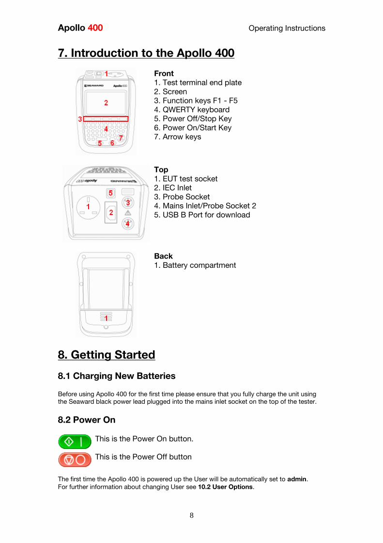
Apollo 400 Operating Instructions
8
7 Introduction to the Apollo 400
Front
1 Test terminal end plate
2 Screen
3 Function keys F1 - F5
4 QWERTY keyboard
5 Power OffStop Key
6 Power OnStart Key
7 Arrow keys
Top
1 EUT test socket
2 IEC Inlet
3 Probe Socket
4 Mains InletProbe Socket 2
5 USB B Port for download
Back
1 Battery compartment
8 Getting Started
81 Charging New Batteries
Before using Apollo 400 for the first time please ensure that you fully charge the unit using
the Seaward black power lead plugged into the mains inlet socket on the top of the tester
82 Power On
This is the Power On button
This is the Power Off button
The first time the Apollo 400 is powered up the User will be automatically set to admin
For further information about changing User see 102 User Options
Apollo 400 Operating Instructions
9
9 User Interface Navigation
91 Screen Layout
1 Information bar
2 Function key icons
3 Test interface sequence table
4 Test interface details
5 Main area
Information Bar This area of the screen shows the Date Time Current User Battery Status and Connection
Status Function Key Icons This area of the screen is used to identify the current action assigned to the function keys Test Interface Sequence Table This area is only displaying in test mode showing the tests within the selected test sequence
This will also show the results and status of the results that have been performed In the
manual mode this table may only show one test Test Interface Details This area is only displayed in test mode showing the details specific to the active test This
includes the measurement an analogue measurement graph the duration and limit Some
tests may show more than more measurement Main Area This area is used to display menu items text fields and forms
92 Menu Navigation
The Apollo is controlled by the function keys The function key icons which are located
above each key are context sensitive and will change depending on the current options
available to you
This is the Home function This will take you back to the
Home screen
This is the Escape function This will return to the previous
screen without saving changes
This is the Accept function This will accept the changes
made in the current screen and move to the next screen
This is the Setup Options function This will take you the
Setup Options screen for the specific function that you are
currently viewing
This is the information key Depending on the current
screen displayed this will display the manual or the Apollo
400 details in the details screen this function will display
the manual
Apollo 400 Operating Instructions
10
This is the MenuOptions key This function will bring up a
context sensitive menu giving the options available for the
current screen
This is the Save key This function is used to save
datachanges that you have made on the current screen
93 Battery Status
While the Apollo 400 is powered on there are periodic checks of the batteries The Apollo
400 will show the status of the batteries
This symbol indicates that the batteries are at 100
capacity
There are several symbols which will display the current
battery voltage When these icons are displayed the
batteries are still good
This symbol indicates that the batteries are low
Although tests performed with the batteries in this state
are still valid all test types may not complete their
intended duration
This symbol indicates that the batteries are discharged
The Apollo 400 will switch itself off after a short period of
time
This symbol indicates that the Apollo 400 is bulk
charging batteries at the full charge current
This symbol indicates that the Apollo 400 is trickle
charging the batteries with reduced charge current This
is known as the Top Up Charge
This symbol indicates that the Apollo 400 has detected a
fault with the battery or battery charger circuit Unplug
the Apollo 400 from the mains supply and wait 2 minutes
before reconnecting the mains If the fault persists then
return the Apollo 400 for service Please note that the battery symbols are not updated in real time and may take a while to
update
94 Test Functionality
There are two buttons which control the starting and stopping of the selected test type
This is the Start Test button This is used to start
electrical tests
This is the Abort Test button This is used to stop
electrical tests
Apollo 400 Operating Instructions
11
10 Main Menu
101 View Saved Data This will allow you to view any data that you have saved in the Apollo 400 By selecting this
icon in the Main Menu you can view a list of all saved Asset IDs by site and location
Use the arrow keys to scroll up and down
This is the Accept function This will open the selected
record
This button allows you to filter records to give a
customised view Select the filters you wish to apply and
press lsquoAcceptrsquo
Once in the record you will be given a list of items under that record such as PAT results and
JPEG images Press Accept to open
This button allows you to delete the selectde record
When viewing a PAT_results record the Menu icon will become available so that you can
view results or print labels When viewing a saved Health amp Safety Form you can edit the report and then save the
changes This will create a new time and date stamped report as well as saving the original
This is the MenuOptions key This function will bring up a
context sensitive menu giving the options available for the
current screen
102 User Options
Apollo 400 has one default user account set up as admin who will have full access to the
product You can add one additional user account to the Apollo 400
This is where you can set up new edit and delete the user account The user can alter their
own screen power save time Auto power down background image avatar and power on
screen and press Save to apply
Use this button to Change User You can then select the
User name to change the current user of the tester
This User Information menu allows users to view their
user type (Expert or Novice)
This is the New User button Here you can set up a new
user account by adding a username and pressing lsquoSave
You can then select their name from the dropdown in the
User Information screen select the type of user (Expert or
Novice
Apollo 400 Operating Instructions
12
This is the Delete User button It will delete whichever
user is currently selected in the lsquoUsernamersquo dropdown
Please note that the admin user cannot be deleted
Press this button to Save changes and return to the
previous screen
103 Bluetooth Setup
Select this icon to setup your Bluetooth accessories to work with the Apollo 400 Switch on
the Bluetooth device you wish to pair with and ensure it is discoverable
This will Bluetooth Search button will search the area for
Bluetooth discoverable devices and return to the previous
menu You can then use the arrow keys to select the
correct Bluetooth ID from the dropdowns for your Bar
Code Scanner Printer or Mobile Device Press lsquoSaversquo
once complete
Press this button to save changes and return to the
previous screen
104 Automatic Test Sequence Editor (PAT Edit)
Although the Apollo 400 comes with a number of pre-defined test sequences you can modify
existing or create new test sequences of their own
From the Menu function key select one of the following options using the arrow keys and the
Accept button
This is the MenuOptions key This function will bring up a
context sensitive menu giving the options available for the
current screen
This is the Accept function This will open the selected
option
Edit Edits the highlighted sequence
Copy Makes a copy of the highlighted test
sequence
Delete Deletes the highlighted test sequence
Add New Adds a new test sequence to the bottom of the
list
Insert New Adds a new test below the highlighted test
sequence
Apollo 400 Operating Instructions
13
When editing a test sequence the following functions are available
This is the Add Test function This will add a new test
directly under the currently selected test
This is the Delete Test function This will delete the
highlighted test from the test sequence
This is the Edit Test function This will edit the
highlighted test
105 Download
Downloading to PATGuard 3
You can download the data from your Apollo to PATGuard 3 software
In the Download menu select To PATGuard in the Download from Apollo dropdown
This button is a way of downloading all data from Apollo
You then need to select one of 2 options from the using dropdown
USB-PC cable
Connect the USB download cable to the USB type B port on the Apollo 400 and to a USB
port on your PC Press Save
Instructions for how to import this download into PATGuard 3 can be found in the PATGuard
3 help files
Bluetooth to Mobile Device
You will need to have a Bluetooth enabled mobile device configured with the Apollo 400 to
use this method See 103 Bluetooth Setup
NB The Apollo 400 does not have the option to download to flash disk
106 Set Date and Time
You can change the date and time in this menu using the arrow keys and number keys
Press this button to save changes and return to the
previous screen
107 Memory
This section will allow you to view how much memory space you have used and how much
is left
This is the Restore button Selecting this will allow you to
clear memory or reset factory settings Select what you
Apollo 400 Operating Instructions
14
would like to restore by pressing the Enter button
Press this button to save changes and return to the
previous screen
11 Portable Appliance Testing
111 Automatic Test Sequence
The Apollo 400 comes with a number of pre-defined test sequences (see Factory Set Test
Sequences) These test sequences can include any combination of electrical tests These
test sequences are performed on equipment to ensure that it meets the safety requirements
outlined in the IET Code of Practice for In-service Inspection and Testing of Electrical
Equipment
1111 Entering Asset Details
Asset ID This is unique identifier for the equipment under
test This can be entered using the keypad or a
barcode scanner (see 103 Bluetooth Setup)
Test
Sequence This is the name of the pre-defined test sequence
which will be performed on the equipment
Site This is the site where the equipment is located
You can choose a site from the dropdown using
the arrow keys or enter a new one
Location This is the location within the site where the
equipment is You can choose a location from the
dropdown using the arrow keys or enter a new
one
Retest Period
(Visual) This is the period in months in which the
equipment should be re-inspected
Retest Period
(Full) This is the period in months in which the
equipment should be re-tested
1112 The Formal Visual Inspection
All pre-set test sequences start with a Visual Inspection
This is the Pass Icon
This is the Fail icon
Apollo 400 Operating Instructions
15
This means that the inspection is not applicable to the
EUT
Pass
All
Pressing the Pass All button will apply a pass to all
relevant inspections and move onto the next test
1113 The Electrical Tests
The Apollo 400 has probe detection that will automatically flag up if you do not have the
correct probe configuration for the test you are trying to perform
During the tests you can see the test duration limit and result on screen see 91 Screen
Layout
Should any test with the sequence fail the sequence will be aborted and you will presented
with the Notes screen by default but this can be changed see 115 PAT Settings
1114 Printing a Label
If you have a TnT Bluetooth printer configured with the Apollo 400 you can print a label after
each test
See 103 Bluetooth Settings to set up a printer
Press this button to go to the print screen and then
again to print a label
This is the Tools function This function allows you to
configure which pre-configured label printer to use
112 Manual Test Interface
The Apollo 400 allows direct access to all of the electrical tests through Manual Mode
Within each test there are a number of function key options
This is the Tools function This function allows you to
configure the test current test type this includes - test duration - test passfail limit
- test typeconnection
Always ensure that you have selected the correct test
connection method in the test for the probe
connections made
Please refer to the Test Functions section for specific information about each test type
Apollo 400 Operating Instructions
16
113 Test Functions
Earth Continuity
Always ensure that the circuit under test is electrically
isolated
Note that measurements can be adversely affected by
parallel resistances of additional circuits or by
transient currents
Connecting a test probe to a hazardous voltage when
a point to point measurement is active will result in
that voltage being present on the other test probe This test is applicable to Class I equipment This test will measure one of the following
resistance between the protective earth terminal in the EUT mains plug and the point
at which a single test probe is applied ndash CLI EUT Continuity
resistance between two test probes ndash Point to Point Continuity resistance between the protective earth terminal in an IEC lead mains plug and the
protective earth terminal in the IEC connector ndash IEC Continuity to ensure that the connection is satisfactory and of sufficiently low resistance The
measurement will be displayed in Ohms There are three possible connection methods for the Earth Continuity test
CLI EUT Continuity
The test is performed between the red
test terminal and the EUT test socket
Point to Point Continuity
This test is performed between the red
test terminal and the black test
terminal Additional test lead is
required
IEC Continuity
The test is performed between the EUT
test socket and the IEC test socket
Always ensure that you have selected the appropriate
test type for the probe connections
Apollo 400 Operating Instructions
17
Selecting test type
In manual PAT test mode the earth continuity test can be switched between a Class I EUT
continuity test and a point to point continuity test as follows
Select Class I Continuity (1) and press the setup key (F3) In the Test Type field select EUT
Continuity Test or Point to Point Continuity Test
During automatic sequences the test type will be as per the test type programmed in the
test sequence Once the correct connections have been made for the selected test type press
the Start button The test will continue until it times out If we wish to abort the current test
press the Stop button Tests on IEC leads CLI EUTs can be performed using a current of
+200mA andor -200mA Tests performed in point to point mode are always performed
using a current +200mA test The direction of the test current can be reversed by switching
the test probes at the point of connection to the appliancecircuit under test
Nulling out the earth continuity test lead(s) resistance
For a more accurate earth continuity measurement the resistance of the test lead(s) can be
zeroed out The feature can be used with both the EUT Continuity and Point to Point
measurement modes
The null facility remains active even if the Apollo 400 is powered off until the feature is
deactivated by pressing the null key again or the Test Type is changed eg if a pair of test
leads are nulled for point to point measurement the null will be deactivated if the Test Type
is changed to EUT Continuity test
Nulling a single test lead
In the manual PAT screen press the setup key (F3) and change the Test Type to EUT
Continuity Test Press save (F4) Connect the earth continuity test lead to the earth continuity
test socket and connect the probe tip to the earth pin of the EUT socket Press Null (F4) to
measure and stored the test lead resistance When the null feature is active the Null icon will
appear on the display
Nulling both test leads
In the manual PAT screen press the setup key (F3) and change the Test Type to Point to
Point Continuity Test Press save (F4) Connect both earth continuity test leads to the earth
continuity test sockets and connect the probe tips together using the supplied alligator clips
Press Null (F4) to measure and stored the test lead resistance When the null feature is active
the Null icon will appear on the display
Insulation Resistance
Always ensure that the circuit under test is electrically
isolated
Connecting a test probe to a hazardous voltage when
a point to point measurement is active will result in
that voltage being present on the other test probe This test is applicable to Class I and Class II equipment This test will measure one of the
following
insulation resistance between live circuits and the protective earth circuit in the EUT
ndash Class I IEC lead insulation test insulation resistance between live circuits and a test probe applied to the EUT ndash
Class II insulation test
Apollo 400 Operating Instructions
18
insulation resistance between two test probes ndash Point to Point Insulation
to ensure that the test points are adequately insulated from one another The measurement
is displayed in MOhms There are three possible connection methods for the Insulation test
CLI and IEC Insulation
The test is performed between the EUT
test socket live and neutral and the EUT
test socket earth pin For IEC leads the other end of the lead
should be connected into the IEC test
socket
CLII Insulation
The test is performed between the EUT
test socket live and neutral and Red
test terminal
Point to Point Insulation
The test is performed between the Red
and Black test terminals both the
continuity test leads are required for
this test Additional test lead is
required
Always ensure that you have selected the correct test
connection method in the test for the probe
connections made
Ensure that the appliance mains switch is in the ON
position
During this test 250V or 500V DC is applied between
the two connections points The 500V DC potential
will be present across the two probe tips during a
Point to Point test
Selecting test type
In manual PAT test mode the insulation test can be switched between a 250V EUT
Insulation test 500V EUT Insulation test 250V Point to Point Insulation test or 500V Point to
Point Insulation test as follows
Apollo 400 Operating Instructions
19
Select Insulation Resistance (2) and press the setup key (F3) In the Test Type field select
the required test
During automatic sequences the test type will be as per the test type programmed in the
test sequence
In manual mode once the correct connections have been made for the selected test type
press the Start button in automatic mode the test will proceed automatically The test will
continue until it times out If we wish to abort the current test press the Stop button The
measurement will be displayed in Mega Ohms If an EUT fails the Insulation test then this may be because of internal filtering or an MOV
Retry the test at 250V or substitute the Insulation test with a Protective Conductor or Touch
Current test
Substitute Leakage
This test is applicable to Class I and Class II equipment This test is used to verify that the
leakage between the mains conductors of the EUT to the EUT earth pin or conductive
accessible surface of the enclosure is to a satisfactory low level There are two possible connection methods for the Substitute Leakage test
CLI and IEC Substitute Leakage
The test is performed between the EUT
test socket live and neutral and the EUT
socket earth pin
For IEC leads the other end of the lead
should be connected into the IEC test
socket
CLII Substitute Leakage The test is performed between the EUT
socket live and neutral and Red test
terminal
During this test 40V AC is applied between the earth pin and both the live and neutral
pins of the appliance mains supply plug In manual mode once the correct connections have been made for the selected test type
press the Start button in automatic mode the test will proceed automatically The test will
continue until it times out If we wish to abort the current test press the Stop button The
measurement will be displayed in milli Amps
This test can prove useful in situations where neither conventional insulation nor flash tests
are acceptable methods of testing the insulation of the appliance
Please note that values for substitute leakage may differ substantially from that of
Apollo 400 Operating Instructions
20
conventional earth leakage tests because of the way that the test is performed (eg it will be
affected by the presence of Neutral-to-Earth suppression capacitors)
Protective Earth (PE) Conductor Current
Always test the earth continuity and insulation
resistance before performing a PE Conductor Current
test
Always check that an appliance with moving parts (eg
an electric drill) is safely mounted to avoid risk of
damage to equipment or personnel
Avoid prolonged repeated use at full load (16A) and
excessive test duration as this may reduce the life of the
unit
Always ensure that appliance and leads which include
RCD protection that the RCD is reset at the beginning
of the test Failure to do so may result in incorrect
measurements being recorded
This test is applicable on Class I
Equipment The Apollo 400 should be connected to
a mains supply The EUT should be
connected into the EUT test socket In manual mode once the correct
connections have been made for the
selected test type press
the Start button in automatic mode the
test will proceed automatically
The test will continue until it times out If we wish to abort the current test press
the Stop button The measurement will be displayed in mA Should the test measurement over range then the test will be aborted immediately and a fail
will be logged
Touch Current
Warning Always test the insulation resistance before
performing a Touch Current test
Warning Always check that an appliance with moving
parts (eg an electric drill) is safely mounted to avoid
risk of damage to equipment or personnel
Attention Avoid prolonged repeated use at full load
(16A) and excessive test duration as this may reduce the
life of the unit
Always ensure that appliance and leads which include
RCD protection that the RCD is reset at the beginning
of the test Failure to do so may result in incorrect
measurements being recorded
Apollo 400 Operating Instructions
21
This test is applicable on Class I and
Class II Equipment The Apollo 400 should be connected to
a mains supply The EUT should be
connected into the EUT socket the red
test terminal should be connected to
point at which the leakage measurement
is required
In manual mode once the correct connections have been made for the selected test type
press the Start button in automatic mode the test will proceed automatically The test will
continue until it times out If we wish to abort the current test press the Stop button The
measurement will be displayed in milli Amps Should the test measurement over range then the test will be aborted immediately and a fail
will be logged
RCD Trip Time
Voltages between the protective conductor and earth
may influence measurements This test will pass a sinusoidal current of 30mA between the EUT socket and the IEC socket
and measure the time it takes for the in-line RCD to trip
Remove all other connections before performing an
RCD test
The Apollo 400 should be connected to
a mains supply The RCD should be
plugged into the EUT test socket and a
connection should be made from the
RCD mains output to the IEC test
socket
Once the correct connections have been made for the selected test type press
the Start button The RCD will be powered and you will be prompted to reset the RCD
When you have reset the RCD the Apollo 400 will count down and then perform the RCD
test the RCD trip time will be displayed The measurement will be displayed in milli seconds
IEC Lead Polarity
The IEC lead input is a test socket and is not intended
to be connected directly to mains Do not connect this
input to the mains supply
The Polarity test checks the wiring
polarity of an IEC lead the IEC should
be plugged into both the EUT and IEC
test sockets
This test can be used to test the wiring polarity of extension leads by plugging the supplied
test IEC lead into the end of the extension lead to complete the circuit to the IEC tests
socket In the automatic sequence editor the Polarity can be added to sequence In the manual
mode the polarity test is already part of a pre-defined test sequence which includes an Earth
Continuity test an Insulation test and the Polarity test
External Leakage Adaptors
Apollo 400 Operating Instructions
22
While using an External Leakage Adaptor the mains
supply will be connected to the EUT through the
adaptor
Ensure that when tests are performed using the
external Leakage Adaptor that the Earth Reverse
option is set to Off
The External Leakage Adaptor test
function is intended to used in
conjunction with the one of Seawards
external leakage adaptors Connect the
external leakage adaptor into the Red
test terminal connect the Earth
Continuity probe into the Black test
terminal
Connect the mains supply and the EUT
to the external leakage adaptor
Note that connecting both the EUT and mains supply to the external leakage adaptor will
connect the mains supply to the EUT
114 Checkbox Verification
A checkbox for the Apollo 400 is available as an optional accessory This can be used to
verify that the Apollo 400 test functions are working correctly When selecting the Checkbox
function follow the onscreen instructions
The Checkbox function will perform a number of
electrical tests Ensure that the onscreen instructions
are followed and that you do not touch the checkbox
during the active tests
12 Updating your Firmware
1 Go to wwwseawardcoukfirmware and save the latest Apollo 400 firmware file on
your PC
2 Power on the unit whilst holding down the F1 button
3 Press F2 to update via PC
4 Follow the onscreen instructions
5 Restart the unit
You can check the firmware version of your tester by
pressing this icon in the Home screen
Apollo 400 Operating Instructions
23
13 Electrical Specification
Earth Continuity
Output Current (Load 2Ω)
Test Voltage (oc)
Measuring Range
Display Range
Resolution Operating Error
Number of tests as per IEC61557-
4
+- 200mA DC with ZAP
gt 4VDC
005 Ωndash 1999 Ω
001 Ω ndash 1999 Ω
001 Ω +-5 + 4 counts
approx 1500
Insulation Test
Test Voltages
Test Current
Test Voltage Accuracy
Measuring Range
Display Range
Resolution Operating Error ( lt 10MΩ ) ( gt 10MΩ )
Number of tests as per IEC61557-
2
500V and 250V DC
1mA minimum for a load of
1kohmvolt lt2mA into sc
+20 -0
010M Ω to 1999M Ω
000M Ω to 1999M Ω
001M Ω +-5 +5 counts +-10 +5 counts approx 1500
Subsitute Leakage Test
Test Voltages
Measuring Range
Display Range
Resolution Operating Error
gt25Vac lt50Vac
020mA to 1999mA
000mA to 1999mA
001mA +-10 +2 digits
Protective Conductor Current
Test Voltage
Display Range
Measurement Range
Resolution
Operating Error
Frequency Response
Supply Voltage maximum
load current 16A
001mA to 1999mA
025mA to 1999mA
001mA
+-5 of reading +- 3 digits
40Hz to 25 kHz
Touch Current
Test Voltage
Display Range
Measurement Range
Resolution
Operating Error
Frequency Response
Supply Voltage maximum
load current 16A
000mA to 350mA
010mA to 350mA
001mA
+-5 of reading +- 2 digits
DC to 25 kHz
Apollo 400 Operating Instructions
24
Load PowerCurrent
Test Voltage
Display Range
Measurement Range
Resolution
Operating Error
Supply Voltage maximum
load current 16A
000 - 1600A
050 - 1600A
001A
+-10 of reading +- 5 digits
Lead Test
Test Voltage
Test 5V DC nominal
Live Neutral checks for oc
sc and crossed
Power Socket Test
Input voltage range
195V ndash 253V AC
Indicates configuration of
voltage potential-
Line potential phase to earth
Line potential phase to neutral
Line potential neutral to earth
RCD Test
Test Voltage
Test Current
Test Current Accuracy
Display Range
Measuring Range
Resolution
Operating Error
230V +10 -15
30mA 150mA rms sinusoidal
30mA -10 +0 150mA +10 -0
0 ndash 2000ms
1ms ndash 2000ms
1ms plusmn1ms
External Leakage
Test Voltage
Display Range
Measuring Range
Resolution
Operating Error
Connected to External
Adapter
0mA - 999mA
025mA - 999mA
001mA +-5 of reading +-2 digits
Apollo 400 Operating Instructions
25
14 Useful Information - 141 Factory Set Test Sequences
Test
Visual Earth Continuity Insulation PE Conductor
Current Touch Current
Substitute
Leakage Wiring
RCD
Trip
Time
Name
Duration
(s)
Limit
(ΩΩ) Duration (s) Voltage
Limit
(MΩΩ)
Duration
(s)
Limit
(mA)
Duration
(s)
Limit
(mA)
Duration
(s)
Limit
(mA)
Limit
(ms)
PortableHandheldIT CLI Yes 5 01 2 500 1
PortableHandheldIT CLII Yes 2 500 2
Fixed Appliance CLI Yes 2 01 5 500 1
Fixed Appliance CLII Yes 5 500 2
IEC Lead 2m Yes 5 02 2 500 1 Yes
13A 5m Surge Protected Lead Yes 5 02 2 250 1 Yes
13A 25m Ext Lead 30mA RCD Yes 5 05 5 08 30
Portable CLI PE Current Yes 5 05 2 250 1 5 08
Portable CLII Touch Current Yes 2 250 2 5 03
IT Equip CLI PE Current Yes 5 01 2 250 1 5 35
IT Equip CLII T ouch Current Yes 2 250 5 03
13A 6m Mains Lead Yes 5 02 2 500 1 Yes
13A 12m Mains Lead Yes 5 03 2 500 1 Yes
13A 24m Mains Lead Yes 5 05 2 500 1 Yes
MovStat CLI 500V Insulation Yes 5 01 2 500 1
MovStat CLII 500V Insulation Yes 2 500 2
MovStat CLI PE Current Yes 5 01 2 250 1 5 35
MovStat CLII Touch Current Yes 2 250 2 5 35
110V HandheldPortable CLI Yes 5 01 2 500 1 2 08
110V HandheldPortable CLII Yes 2 500 2 2 03
110V MovableStationary CLI Yes 5 01 2 500 1 2 35
110V MovableStationary CLII Yes 2 500 2 2 03
110V 25m Lead
RpeampInsulation Yes 5 05 2 500 1
Visual Only Yes
Apollo 400 Operating Instructions
26
142 Other Information
Parameter Default Min Max
Earth Continuity PF limit (Ω) 01 001 1999
Earth Continuity Duration (s) 5 2 30
Insulation Resistance PF limit (MΩ) 1 001 1999
Insulation Resistance Duration (s) 5 2 30
Substitute Leakage PF limit (mA) 075 025 15
Substitute Leakage Duration (s) 5 2 30
IEC Cord Earth Continuity PF limit
(ohms) 01 001 5
IEC Cord Insulation PF limit (MΩ) 1 001 1999
Touch Current PF limit (mA) 025 025 350
Touch Current Duration (s) 5 2 30
PE Conductor Current PF limit (mA) 075 025 1999
PE Conductor Current Duration (s) 5 2 30
External Adapter Continuity (Ω) 01 001 5
External Adapter Leakage (mA) 075 025 999
External Adapter Duration (s) 5 2 30
RCD 30mA trip time (ms) 200 1 2000
RCD 150mA trip time (ms) 40 1 40
Number of tests in a test sequence 1 60
Characters in a test sequence name 1 30
Characters in a User Test name 1 15
Characters in a User Test Unit 15
Total number of Test Sequences 25
Test Results (typical) 2000
Sites 50
Characters in Site name 1 15
Locations 50
Characters in Location name 1 15
Users (including admin) 2
Characters in User name 1 15
Comments List 50
Characters in Comment 25
Characters in Asset ID 1 15
Apollo 400 Operating Instructions
27
15 Environmental Conditions
The Apollo 400 has been designed to perform tests and measurements in a dry environment
Maximum barometric elevation for making measurements is 2000M
Pollution degree 2 according to IEC 60529
Electromagnetic compatibility (EMC) Interference immunity and emitted interference
conforming to IEC 61326-1
Operating temperature range of 0 to 40 degrees C without moisture condensation
Operating Altitude 0 to 2000 metres
16 Maintenance
161 Charging the battery pack
The battery pack will be charged whenever the Apollo 400 is connected to the mains supply
regardless of whether it is switched on or off
The typical charging current is set to 500mA but this may vary as the instrument also
includes pre-charge and top up charge modes
When no tests are being performed the battery pack will be fully re-charged after 7 hours
162 Securing the Apollo 400
Under certain conditions safe operation of the Apollo 400 can no longer be assumed
Visible damage of the instrument case
Incorrect measurement results
Recognisable abuse to the instrument due to prolonged storage under improper conditions
Recognisable abuse to the instrument due to extraordinary transportation stress
In these case the Apollo 400 should be immediately switched off disconnected from any test
and measurement function and secured to prevent any further use
163 Cleaning the Apollo 400
Clean the external case of the Apollo 400 with a dry clean cloth
Avoid using solvents and abrasive scouring agents to clean the external case of the Apollo
400
Apollo 400 Operating Instructions
28
164 Replacing the battery pack
Before opening the Apollo 400 battery compartment
ensure that all test leads and accessories are
disconnected
Power off the instrument
Disconnect all test leads and accessories
Position the instrument face down and remove the screw holding the battery compartment
cover in place
Remove the battery compartment cover
Remove the battery pack from the compartment and unplug the 4 way connector
Connect the 4 way connector of the new battery to the 4 way header in the battery
compartment put the battery pack into the compartment
Relocate the battery compartment cover and fasten in position with the battery compartment
screw
ONLY USE A REPLACEMENT BATTERY PACK THAT HAS BEEN SUPPLIED BY SEAWARD
OR A SEAWARD APPROVED DISTRIBUTOR
17 Support
The Apollo 400 must be registered with Seaward before support will be made available For Technical Support contact Tel (+44) 191 587 8718
For help or advice on Service and Calibration contact
CalibrationHouse Seaward Electronic Bracken Hill South West Industrial Estate Peterlee Co Durham SR8 2SW England Tel (+44) 191 5878739 (+44) 191 5878737 Email serviceseawardcouk
Calibration House is part of the Seaward Group
Apollo 400 Operating Instructions
29
171 Register your product here-
wwwseawardcouk 172 Calibration Services-
wwwcalibrationhousecouk Bracken Hill South West Industrial Estate Peterlee County Durham SR8 2SW Co Durham SR8 2SW England Tel (+44) 191 5863511 Some icons provided by Fat Cow (httpwwwfatcowcomfree-icons) Based in part on the work of the Qwt project (httpqwtsfnet)
Apollo 400A simple no-nonsense PAT tester with fast data entry and storage for up to 2000appliance records
Key Featuresn High definition colour displayn Store 2000 appliance recordsn Remote data transfer from field to office n Bluetooth connectivity
Electrical Test Functionsn Low current earth continuity test guaranteeing accurate measurement n Point to point testing (earth continuity and insulation resistance)n Insulation resistancen IEC lead testn Protective conductor currentn Touch currentn Load powercurrentn Alternative leakage currentn RCD testn Power socket test
Ideal Forn Electrical Contractorsn Facilities Managersn Operations Managers
Apollo 400 offers simple electrical safety testing with straightforward data entryusing the intuitive QWERTY keypad
A comprehensive range of electrical safety tests ensure compliance with theIET 4th Edition Code of Practice whilst remote data transfer and USB downloadmakes data management easy and efficient
The Apollo 400 is ideal for mid-volume PAT testing where detailed records arerequired
Streamline the PAT testing process further by using the Apollo 400 with acompatible label printer barcode scanner and PATGuard 3 software
wwwseawardcoukapollo400
Tel +44 (0) 191 587 8741Email salesseawardcouk
Requires optional accessory (part number 380A983)
Straightforward PAT testing with simple data managementApollo 400 offers a comprehensive suite of electrical safetytests to enable any workplace appliance to be tested including3-phase equipment fixed appliances and RCDs
The QWERTY keypad enables asset information to be entered quicklyand easily while a large colour display with an intuitive menu structure makesthe Apollo 400 simple to grasp Lightweight and small in size with battery or mainspower modes the Apollo 400 is good to go in seconds allowing more appliances to betested without downtime for boot-up or a battery re-charge
Superb software for total traceabilityApollo 400 has an internal memory capable of storing up to 2000electrical test records Its compatibility with Seawardrsquos PATGuard 3software means that complete test records are easily managed ona PC
Transfer data to the PC remotely using the Bluetooth function anda smartphone or download the results via a USB cable directly toa PC Once downloaded to PATGuard 3 it is easy to keep track ofthe history of test and inspections as well as produce reportscertificates and invoices ndash offering total peace of mind and quickereasier management of scheduling inspections and tests
Download a free trial at wwwseawardcoukpg3trial
wwwseawardcoukapollo400
Tel +44 (0) 191 587 8741Email salesseawardcouk
additional accessory required for point to point testing
u Accessory BundlesThe Apollo 400 is available to buy with a selectionof optional accessory bundles to help you get themost out of your tester
Apollo 400 is supplied as standard with a UKAScalibration certificate and a 2 yearmanufacturerrsquos warranty (subject to terms andconditions)
Greater efficiency through useful accessoriesAs with many Seaward PAT testers the Apollo 400 is compatible with arange of printers and barcode scanners further speeding up the processof asset recognition testing and labelling
Also available in this range
A multi-tasking and fully customisable PAT with additionalhealth and safety features and on-board camera forunrivalled record keeping
Apollo 600 includes a universal risk assessment tool andthe ability to store up to 50000 appliance records plus2000 images - providing visual evidence of testenvironments perfect for advanced record-keeping inorganisations with high-volume workplace test andinspection routines
Apollo 600Multi-tasking PAT tester with on-board camera
wwwseawardcoukapollo400
Tel +44 (0) 191 587 8741Email salesseawardcouk
A powerful PAT tester with a built-in PAT retest calculatorand flexible user-configurable sequences for recordingany non-electrical workplace test or inspection
The ability to customise a number of settings and a largememory to store up to 10000 appliance records makesthe Apollo 500 a versatile and dependable tool for highvolume PAT testing
Apollo 500A fast amp fully customisable and versatile PAT tester
Optional accessory bundles available Part Number
Elite Bundle n Test n Tag Elite 2 rugged portable printer
n Test n Tag printer labels x 4
n Bluetooth barcode scanner
n Apollo kit carry case
n 110V adapter
Includes Apollo 400 tester
380A978
Elite Bundle +Software
PLUS PATGuard 3 software 1yr licence 380A979
Pro Bundle n Test n Tag Pro lightweight portable printer
n Test n Tag printer labels x 4
n Bluetooth barcode scanner
n Apollo kit carry case
n 110V adapter
Includes Apollo 400 tester
380A980
Pro Bundle +Software PLUS PATGuard 3 software 1yr licence 380A981
wwwseawardcoukapollo400
Tel +44 (0) 191 587 8741Email salesseawardcouk
Apollo 400 Apollo 500 Apollo 600
General Features
Battery amp mains powered n n n
Colour Screen amp QWERTY keypad n n n
Large internal memory 2000 records 10000 records 50000 records
Scanner amp printer compatible n n n
Password controlled user accounts n n
Set up multiple user accounts with varyinglevels of privileges
n n
Clone facility to set up multiple testers n n
Checkbox supplied as standard n n
On-board user manual n n
Test amp InspectionFeatures
Auto-increment asset ID n n
PAT Setup option to allow for custom menus n n
Enter asset description after test usingkeypad or barcode scanner
n n n
Comprehensive electrical safety test features n n n
Point to point measurement (Rpe amp IR)
n
(optional
accessory
required)
n n
User configurable electrical testvisualinspection sequences 25 100 100
User set sites amp locations 50 100 100
Risk based retest period calculator n n
User definable comments lines against testrecords
n n
Configurable checklists for any workplacetest or inspection (user tests)
n n
On-board camera n
Universal risk assessment n
Health amp safety certificates n
Data Transfer
Bluetooth connectivity n n n
Barcode scanner connectivity n n n
Print Pass amp Fail labels n n n
Add your company logo to labels n n
Select from various label formats to print n n
Remote data transfer via mobile device n
(Android only)
n
(Android only)
n
(Android and iOS)
Download to PC via USB cable n n n
Filter results to be downloaded n n
Upload previous results to tester for retest n n
Data transfer via USB flash drive n
Apollo Series Comparison Chart
PAT TESTS
Earth ContinuityTest Current +- 200mA DC Display Range 001 ndash 1999ΩPass Value User Defined
Insulation ResistanceTest Voltage 500V 250VDC 1mA nominalDisplay Range 001MΩ - 1999MΩPass Value User Defined
IEC Lead TestTest Voltage 5VAC nominalTest Live Neutral Checks for oc sc and crossed
Protective Conductor CurrentLoad
Test Voltage Supply voltage maximum load current 16A Display Ranges 001mA to 1999mA Pass Value User Defined
Touch Current
Test Voltage Supply Voltage maximum load current 16ADisplay Range 000 ndash 350mA Pass Value User defined
Load PowerCurrent
Test Voltage Supply Voltage maximum load current 16ATest Duration Programmable up to a maximum of 255s depending on load ie max duration is reduced for high loadsDisplay Range 000kVA ndash 400kVA 000A ndash 1600A
Alternative Leakage Current
Test Voltages gt25VAC lt50VAC Display Range 000mA to 1999mAPass Value User Defined
RCD Test
Test Voltage 230V +10 -15Test Current 30mA 150mA rms sinusoidalDisplay Range 0ms - 2000ms (30mA) 0-40ms (150mA)Test Method Internal isolation to avoid tripping distribution board RCD
Power Socket Test
Voltage Range 207V ndash 253VACIndicates configuration of voltage potential-Line potential phase to earthLine potential phase to neutralLine potential neutral to earth
General
Memory Size 2000 recordsWeight 15kgDimensions 230mm x 150mm x 100mmPower Source Mains or rechargeable battery pack
Standard Accessories (supplied with Apollo 400)30 day free trial of PATGuard 3 software 1x red test lead and probe with crocodile clip05m IEC leadMains power leadUSB download cableQuick start guideUKAS calibration certificate
Optional Accessories Test n Tag Elite 2 Bluetooth printer with roll of small labels (339A995)Test n Tag Pro Bluetooth printer with roll of small labels (339A987)Roll of small labels (approx 350 off 52 x 25mm labels) (339A947)Additional black test lead and probe with crocodile clip (for point to point testing) (380A983)Bluetooth barcode scanner (339A923)110V test adaptor (270A076)110V to IEC adapter (344A050)Apollo checkbox (380A953)3 Phase Leakage Adaptor 5 Star 16A (391A920)3 Phase Leakage Adaptor 5 Star 32A (391A910)3 Phase Adapter Delta 4 pin 16A 415V (for Rpe amp IR) (209A910)3 Phase Adapter Star 5 pin 16A 415V (for Rpe amp IR) (209A911)3 Phase Adapter Delta 4 pin 32A 415V (for Rpe amp IR) (209A912)3 Phase Adapter Star 5 pin 32A 415V (for Rpe amp IR) (209A913)Professional Seaward kit bag (71G109)Apollo carry case (380A952)PATGuard 3 software ndash download 30 day free trial atwwwseawardcoukpg3trial
Part NumbersApollo 400 standard package 380A920Apollo 400 with Elite accessory bundle 380A978Apollo 400 with Elite accessory bundle amp PATGuard 3 one year licence380A979Apollo 400 with Pro accessory bundle 380A980Apollo 400 with Pro accessory bundle amp PATGuard 3 one year licence380A981
TrainingSeaward offer a range of PAT testing courses including City amp GuildsGo to wwwseawardcouktraining for more information
Services2 year warranty (subject to terms and conditions available atwwwseawardcoukwarranty24)Service amp Calibration by CalibrationhouseGo to wwwcalibrationhousecom for more information
Technical Specifications
Part of
Rev 12
wwwseawardcoukapollo400
Tel +44 (0) 191 587 8741Email salesseawardcouk
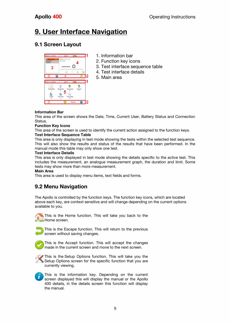
Apollo 400 Operating Instructions
9
9 User Interface Navigation
91 Screen Layout
1 Information bar
2 Function key icons
3 Test interface sequence table
4 Test interface details
5 Main area
Information Bar This area of the screen shows the Date Time Current User Battery Status and Connection
Status Function Key Icons This area of the screen is used to identify the current action assigned to the function keys Test Interface Sequence Table This area is only displaying in test mode showing the tests within the selected test sequence
This will also show the results and status of the results that have been performed In the
manual mode this table may only show one test Test Interface Details This area is only displayed in test mode showing the details specific to the active test This
includes the measurement an analogue measurement graph the duration and limit Some
tests may show more than more measurement Main Area This area is used to display menu items text fields and forms
92 Menu Navigation
The Apollo is controlled by the function keys The function key icons which are located
above each key are context sensitive and will change depending on the current options
available to you
This is the Home function This will take you back to the
Home screen
This is the Escape function This will return to the previous
screen without saving changes
This is the Accept function This will accept the changes
made in the current screen and move to the next screen
This is the Setup Options function This will take you the
Setup Options screen for the specific function that you are
currently viewing
This is the information key Depending on the current
screen displayed this will display the manual or the Apollo
400 details in the details screen this function will display
the manual
Apollo 400 Operating Instructions
10
This is the MenuOptions key This function will bring up a
context sensitive menu giving the options available for the
current screen
This is the Save key This function is used to save
datachanges that you have made on the current screen
93 Battery Status
While the Apollo 400 is powered on there are periodic checks of the batteries The Apollo
400 will show the status of the batteries
This symbol indicates that the batteries are at 100
capacity
There are several symbols which will display the current
battery voltage When these icons are displayed the
batteries are still good
This symbol indicates that the batteries are low
Although tests performed with the batteries in this state
are still valid all test types may not complete their
intended duration
This symbol indicates that the batteries are discharged
The Apollo 400 will switch itself off after a short period of
time
This symbol indicates that the Apollo 400 is bulk
charging batteries at the full charge current
This symbol indicates that the Apollo 400 is trickle
charging the batteries with reduced charge current This
is known as the Top Up Charge
This symbol indicates that the Apollo 400 has detected a
fault with the battery or battery charger circuit Unplug
the Apollo 400 from the mains supply and wait 2 minutes
before reconnecting the mains If the fault persists then
return the Apollo 400 for service Please note that the battery symbols are not updated in real time and may take a while to
update
94 Test Functionality
There are two buttons which control the starting and stopping of the selected test type
This is the Start Test button This is used to start
electrical tests
This is the Abort Test button This is used to stop
electrical tests
Apollo 400 Operating Instructions
11
10 Main Menu
101 View Saved Data This will allow you to view any data that you have saved in the Apollo 400 By selecting this
icon in the Main Menu you can view a list of all saved Asset IDs by site and location
Use the arrow keys to scroll up and down
This is the Accept function This will open the selected
record
This button allows you to filter records to give a
customised view Select the filters you wish to apply and
press lsquoAcceptrsquo
Once in the record you will be given a list of items under that record such as PAT results and
JPEG images Press Accept to open
This button allows you to delete the selectde record
When viewing a PAT_results record the Menu icon will become available so that you can
view results or print labels When viewing a saved Health amp Safety Form you can edit the report and then save the
changes This will create a new time and date stamped report as well as saving the original
This is the MenuOptions key This function will bring up a
context sensitive menu giving the options available for the
current screen
102 User Options
Apollo 400 has one default user account set up as admin who will have full access to the
product You can add one additional user account to the Apollo 400
This is where you can set up new edit and delete the user account The user can alter their
own screen power save time Auto power down background image avatar and power on
screen and press Save to apply
Use this button to Change User You can then select the
User name to change the current user of the tester
This User Information menu allows users to view their
user type (Expert or Novice)
This is the New User button Here you can set up a new
user account by adding a username and pressing lsquoSave
You can then select their name from the dropdown in the
User Information screen select the type of user (Expert or
Novice
Apollo 400 Operating Instructions
12
This is the Delete User button It will delete whichever
user is currently selected in the lsquoUsernamersquo dropdown
Please note that the admin user cannot be deleted
Press this button to Save changes and return to the
previous screen
103 Bluetooth Setup
Select this icon to setup your Bluetooth accessories to work with the Apollo 400 Switch on
the Bluetooth device you wish to pair with and ensure it is discoverable
This will Bluetooth Search button will search the area for
Bluetooth discoverable devices and return to the previous
menu You can then use the arrow keys to select the
correct Bluetooth ID from the dropdowns for your Bar
Code Scanner Printer or Mobile Device Press lsquoSaversquo
once complete
Press this button to save changes and return to the
previous screen
104 Automatic Test Sequence Editor (PAT Edit)
Although the Apollo 400 comes with a number of pre-defined test sequences you can modify
existing or create new test sequences of their own
From the Menu function key select one of the following options using the arrow keys and the
Accept button
This is the MenuOptions key This function will bring up a
context sensitive menu giving the options available for the
current screen
This is the Accept function This will open the selected
option
Edit Edits the highlighted sequence
Copy Makes a copy of the highlighted test
sequence
Delete Deletes the highlighted test sequence
Add New Adds a new test sequence to the bottom of the
list
Insert New Adds a new test below the highlighted test
sequence
Apollo 400 Operating Instructions
13
When editing a test sequence the following functions are available
This is the Add Test function This will add a new test
directly under the currently selected test
This is the Delete Test function This will delete the
highlighted test from the test sequence
This is the Edit Test function This will edit the
highlighted test
105 Download
Downloading to PATGuard 3
You can download the data from your Apollo to PATGuard 3 software
In the Download menu select To PATGuard in the Download from Apollo dropdown
This button is a way of downloading all data from Apollo
You then need to select one of 2 options from the using dropdown
USB-PC cable
Connect the USB download cable to the USB type B port on the Apollo 400 and to a USB
port on your PC Press Save
Instructions for how to import this download into PATGuard 3 can be found in the PATGuard
3 help files
Bluetooth to Mobile Device
You will need to have a Bluetooth enabled mobile device configured with the Apollo 400 to
use this method See 103 Bluetooth Setup
NB The Apollo 400 does not have the option to download to flash disk
106 Set Date and Time
You can change the date and time in this menu using the arrow keys and number keys
Press this button to save changes and return to the
previous screen
107 Memory
This section will allow you to view how much memory space you have used and how much
is left
This is the Restore button Selecting this will allow you to
clear memory or reset factory settings Select what you
Apollo 400 Operating Instructions
14
would like to restore by pressing the Enter button
Press this button to save changes and return to the
previous screen
11 Portable Appliance Testing
111 Automatic Test Sequence
The Apollo 400 comes with a number of pre-defined test sequences (see Factory Set Test
Sequences) These test sequences can include any combination of electrical tests These
test sequences are performed on equipment to ensure that it meets the safety requirements
outlined in the IET Code of Practice for In-service Inspection and Testing of Electrical
Equipment
1111 Entering Asset Details
Asset ID This is unique identifier for the equipment under
test This can be entered using the keypad or a
barcode scanner (see 103 Bluetooth Setup)
Test
Sequence This is the name of the pre-defined test sequence
which will be performed on the equipment
Site This is the site where the equipment is located
You can choose a site from the dropdown using
the arrow keys or enter a new one
Location This is the location within the site where the
equipment is You can choose a location from the
dropdown using the arrow keys or enter a new
one
Retest Period
(Visual) This is the period in months in which the
equipment should be re-inspected
Retest Period
(Full) This is the period in months in which the
equipment should be re-tested
1112 The Formal Visual Inspection
All pre-set test sequences start with a Visual Inspection
This is the Pass Icon
This is the Fail icon
Apollo 400 Operating Instructions
15
This means that the inspection is not applicable to the
EUT
Pass
All
Pressing the Pass All button will apply a pass to all
relevant inspections and move onto the next test
1113 The Electrical Tests
The Apollo 400 has probe detection that will automatically flag up if you do not have the
correct probe configuration for the test you are trying to perform
During the tests you can see the test duration limit and result on screen see 91 Screen
Layout
Should any test with the sequence fail the sequence will be aborted and you will presented
with the Notes screen by default but this can be changed see 115 PAT Settings
1114 Printing a Label
If you have a TnT Bluetooth printer configured with the Apollo 400 you can print a label after
each test
See 103 Bluetooth Settings to set up a printer
Press this button to go to the print screen and then
again to print a label
This is the Tools function This function allows you to
configure which pre-configured label printer to use
112 Manual Test Interface
The Apollo 400 allows direct access to all of the electrical tests through Manual Mode
Within each test there are a number of function key options
This is the Tools function This function allows you to
configure the test current test type this includes - test duration - test passfail limit
- test typeconnection
Always ensure that you have selected the correct test
connection method in the test for the probe
connections made
Please refer to the Test Functions section for specific information about each test type
Apollo 400 Operating Instructions
16
113 Test Functions
Earth Continuity
Always ensure that the circuit under test is electrically
isolated
Note that measurements can be adversely affected by
parallel resistances of additional circuits or by
transient currents
Connecting a test probe to a hazardous voltage when
a point to point measurement is active will result in
that voltage being present on the other test probe This test is applicable to Class I equipment This test will measure one of the following
resistance between the protective earth terminal in the EUT mains plug and the point
at which a single test probe is applied ndash CLI EUT Continuity
resistance between two test probes ndash Point to Point Continuity resistance between the protective earth terminal in an IEC lead mains plug and the
protective earth terminal in the IEC connector ndash IEC Continuity to ensure that the connection is satisfactory and of sufficiently low resistance The
measurement will be displayed in Ohms There are three possible connection methods for the Earth Continuity test
CLI EUT Continuity
The test is performed between the red
test terminal and the EUT test socket
Point to Point Continuity
This test is performed between the red
test terminal and the black test
terminal Additional test lead is
required
IEC Continuity
The test is performed between the EUT
test socket and the IEC test socket
Always ensure that you have selected the appropriate
test type for the probe connections
Apollo 400 Operating Instructions
17
Selecting test type
In manual PAT test mode the earth continuity test can be switched between a Class I EUT
continuity test and a point to point continuity test as follows
Select Class I Continuity (1) and press the setup key (F3) In the Test Type field select EUT
Continuity Test or Point to Point Continuity Test
During automatic sequences the test type will be as per the test type programmed in the
test sequence Once the correct connections have been made for the selected test type press
the Start button The test will continue until it times out If we wish to abort the current test
press the Stop button Tests on IEC leads CLI EUTs can be performed using a current of
+200mA andor -200mA Tests performed in point to point mode are always performed
using a current +200mA test The direction of the test current can be reversed by switching
the test probes at the point of connection to the appliancecircuit under test
Nulling out the earth continuity test lead(s) resistance
For a more accurate earth continuity measurement the resistance of the test lead(s) can be
zeroed out The feature can be used with both the EUT Continuity and Point to Point
measurement modes
The null facility remains active even if the Apollo 400 is powered off until the feature is
deactivated by pressing the null key again or the Test Type is changed eg if a pair of test
leads are nulled for point to point measurement the null will be deactivated if the Test Type
is changed to EUT Continuity test
Nulling a single test lead
In the manual PAT screen press the setup key (F3) and change the Test Type to EUT
Continuity Test Press save (F4) Connect the earth continuity test lead to the earth continuity
test socket and connect the probe tip to the earth pin of the EUT socket Press Null (F4) to
measure and stored the test lead resistance When the null feature is active the Null icon will
appear on the display
Nulling both test leads
In the manual PAT screen press the setup key (F3) and change the Test Type to Point to
Point Continuity Test Press save (F4) Connect both earth continuity test leads to the earth
continuity test sockets and connect the probe tips together using the supplied alligator clips
Press Null (F4) to measure and stored the test lead resistance When the null feature is active
the Null icon will appear on the display
Insulation Resistance
Always ensure that the circuit under test is electrically
isolated
Connecting a test probe to a hazardous voltage when
a point to point measurement is active will result in
that voltage being present on the other test probe This test is applicable to Class I and Class II equipment This test will measure one of the
following
insulation resistance between live circuits and the protective earth circuit in the EUT
ndash Class I IEC lead insulation test insulation resistance between live circuits and a test probe applied to the EUT ndash
Class II insulation test
Apollo 400 Operating Instructions
18
insulation resistance between two test probes ndash Point to Point Insulation
to ensure that the test points are adequately insulated from one another The measurement
is displayed in MOhms There are three possible connection methods for the Insulation test
CLI and IEC Insulation
The test is performed between the EUT
test socket live and neutral and the EUT
test socket earth pin For IEC leads the other end of the lead
should be connected into the IEC test
socket
CLII Insulation
The test is performed between the EUT
test socket live and neutral and Red
test terminal
Point to Point Insulation
The test is performed between the Red
and Black test terminals both the
continuity test leads are required for
this test Additional test lead is
required
Always ensure that you have selected the correct test
connection method in the test for the probe
connections made
Ensure that the appliance mains switch is in the ON
position
During this test 250V or 500V DC is applied between
the two connections points The 500V DC potential
will be present across the two probe tips during a
Point to Point test
Selecting test type
In manual PAT test mode the insulation test can be switched between a 250V EUT
Insulation test 500V EUT Insulation test 250V Point to Point Insulation test or 500V Point to
Point Insulation test as follows
Apollo 400 Operating Instructions
19
Select Insulation Resistance (2) and press the setup key (F3) In the Test Type field select
the required test
During automatic sequences the test type will be as per the test type programmed in the
test sequence
In manual mode once the correct connections have been made for the selected test type
press the Start button in automatic mode the test will proceed automatically The test will
continue until it times out If we wish to abort the current test press the Stop button The
measurement will be displayed in Mega Ohms If an EUT fails the Insulation test then this may be because of internal filtering or an MOV
Retry the test at 250V or substitute the Insulation test with a Protective Conductor or Touch
Current test
Substitute Leakage
This test is applicable to Class I and Class II equipment This test is used to verify that the
leakage between the mains conductors of the EUT to the EUT earth pin or conductive
accessible surface of the enclosure is to a satisfactory low level There are two possible connection methods for the Substitute Leakage test
CLI and IEC Substitute Leakage
The test is performed between the EUT
test socket live and neutral and the EUT
socket earth pin
For IEC leads the other end of the lead
should be connected into the IEC test
socket
CLII Substitute Leakage The test is performed between the EUT
socket live and neutral and Red test
terminal
During this test 40V AC is applied between the earth pin and both the live and neutral
pins of the appliance mains supply plug In manual mode once the correct connections have been made for the selected test type
press the Start button in automatic mode the test will proceed automatically The test will
continue until it times out If we wish to abort the current test press the Stop button The
measurement will be displayed in milli Amps
This test can prove useful in situations where neither conventional insulation nor flash tests
are acceptable methods of testing the insulation of the appliance
Please note that values for substitute leakage may differ substantially from that of
Apollo 400 Operating Instructions
20
conventional earth leakage tests because of the way that the test is performed (eg it will be
affected by the presence of Neutral-to-Earth suppression capacitors)
Protective Earth (PE) Conductor Current
Always test the earth continuity and insulation
resistance before performing a PE Conductor Current
test
Always check that an appliance with moving parts (eg
an electric drill) is safely mounted to avoid risk of
damage to equipment or personnel
Avoid prolonged repeated use at full load (16A) and
excessive test duration as this may reduce the life of the
unit
Always ensure that appliance and leads which include
RCD protection that the RCD is reset at the beginning
of the test Failure to do so may result in incorrect
measurements being recorded
This test is applicable on Class I
Equipment The Apollo 400 should be connected to
a mains supply The EUT should be
connected into the EUT test socket In manual mode once the correct
connections have been made for the
selected test type press
the Start button in automatic mode the
test will proceed automatically
The test will continue until it times out If we wish to abort the current test press
the Stop button The measurement will be displayed in mA Should the test measurement over range then the test will be aborted immediately and a fail
will be logged
Touch Current
Warning Always test the insulation resistance before
performing a Touch Current test
Warning Always check that an appliance with moving
parts (eg an electric drill) is safely mounted to avoid
risk of damage to equipment or personnel
Attention Avoid prolonged repeated use at full load
(16A) and excessive test duration as this may reduce the
life of the unit
Always ensure that appliance and leads which include
RCD protection that the RCD is reset at the beginning
of the test Failure to do so may result in incorrect
measurements being recorded
Apollo 400 Operating Instructions
21
This test is applicable on Class I and
Class II Equipment The Apollo 400 should be connected to
a mains supply The EUT should be
connected into the EUT socket the red
test terminal should be connected to
point at which the leakage measurement
is required
In manual mode once the correct connections have been made for the selected test type
press the Start button in automatic mode the test will proceed automatically The test will
continue until it times out If we wish to abort the current test press the Stop button The
measurement will be displayed in milli Amps Should the test measurement over range then the test will be aborted immediately and a fail
will be logged
RCD Trip Time
Voltages between the protective conductor and earth
may influence measurements This test will pass a sinusoidal current of 30mA between the EUT socket and the IEC socket
and measure the time it takes for the in-line RCD to trip
Remove all other connections before performing an
RCD test
The Apollo 400 should be connected to
a mains supply The RCD should be
plugged into the EUT test socket and a
connection should be made from the
RCD mains output to the IEC test
socket
Once the correct connections have been made for the selected test type press
the Start button The RCD will be powered and you will be prompted to reset the RCD
When you have reset the RCD the Apollo 400 will count down and then perform the RCD
test the RCD trip time will be displayed The measurement will be displayed in milli seconds
IEC Lead Polarity
The IEC lead input is a test socket and is not intended
to be connected directly to mains Do not connect this
input to the mains supply
The Polarity test checks the wiring
polarity of an IEC lead the IEC should
be plugged into both the EUT and IEC
test sockets
This test can be used to test the wiring polarity of extension leads by plugging the supplied
test IEC lead into the end of the extension lead to complete the circuit to the IEC tests
socket In the automatic sequence editor the Polarity can be added to sequence In the manual
mode the polarity test is already part of a pre-defined test sequence which includes an Earth
Continuity test an Insulation test and the Polarity test
External Leakage Adaptors
Apollo 400 Operating Instructions
22
While using an External Leakage Adaptor the mains
supply will be connected to the EUT through the
adaptor
Ensure that when tests are performed using the
external Leakage Adaptor that the Earth Reverse
option is set to Off
The External Leakage Adaptor test
function is intended to used in
conjunction with the one of Seawards
external leakage adaptors Connect the
external leakage adaptor into the Red
test terminal connect the Earth
Continuity probe into the Black test
terminal
Connect the mains supply and the EUT
to the external leakage adaptor
Note that connecting both the EUT and mains supply to the external leakage adaptor will
connect the mains supply to the EUT
114 Checkbox Verification
A checkbox for the Apollo 400 is available as an optional accessory This can be used to
verify that the Apollo 400 test functions are working correctly When selecting the Checkbox
function follow the onscreen instructions
The Checkbox function will perform a number of
electrical tests Ensure that the onscreen instructions
are followed and that you do not touch the checkbox
during the active tests
12 Updating your Firmware
1 Go to wwwseawardcoukfirmware and save the latest Apollo 400 firmware file on
your PC
2 Power on the unit whilst holding down the F1 button
3 Press F2 to update via PC
4 Follow the onscreen instructions
5 Restart the unit
You can check the firmware version of your tester by
pressing this icon in the Home screen
Apollo 400 Operating Instructions
23
13 Electrical Specification
Earth Continuity
Output Current (Load 2Ω)
Test Voltage (oc)
Measuring Range
Display Range
Resolution Operating Error
Number of tests as per IEC61557-
4
+- 200mA DC with ZAP
gt 4VDC
005 Ωndash 1999 Ω
001 Ω ndash 1999 Ω
001 Ω +-5 + 4 counts
approx 1500
Insulation Test
Test Voltages
Test Current
Test Voltage Accuracy
Measuring Range
Display Range
Resolution Operating Error ( lt 10MΩ ) ( gt 10MΩ )
Number of tests as per IEC61557-
2
500V and 250V DC
1mA minimum for a load of
1kohmvolt lt2mA into sc
+20 -0
010M Ω to 1999M Ω
000M Ω to 1999M Ω
001M Ω +-5 +5 counts +-10 +5 counts approx 1500
Subsitute Leakage Test
Test Voltages
Measuring Range
Display Range
Resolution Operating Error
gt25Vac lt50Vac
020mA to 1999mA
000mA to 1999mA
001mA +-10 +2 digits
Protective Conductor Current
Test Voltage
Display Range
Measurement Range
Resolution
Operating Error
Frequency Response
Supply Voltage maximum
load current 16A
001mA to 1999mA
025mA to 1999mA
001mA
+-5 of reading +- 3 digits
40Hz to 25 kHz
Touch Current
Test Voltage
Display Range
Measurement Range
Resolution
Operating Error
Frequency Response
Supply Voltage maximum
load current 16A
000mA to 350mA
010mA to 350mA
001mA
+-5 of reading +- 2 digits
DC to 25 kHz
Apollo 400 Operating Instructions
24
Load PowerCurrent
Test Voltage
Display Range
Measurement Range
Resolution
Operating Error
Supply Voltage maximum
load current 16A
000 - 1600A
050 - 1600A
001A
+-10 of reading +- 5 digits
Lead Test
Test Voltage
Test 5V DC nominal
Live Neutral checks for oc
sc and crossed
Power Socket Test
Input voltage range
195V ndash 253V AC
Indicates configuration of
voltage potential-
Line potential phase to earth
Line potential phase to neutral
Line potential neutral to earth
RCD Test
Test Voltage
Test Current
Test Current Accuracy
Display Range
Measuring Range
Resolution
Operating Error
230V +10 -15
30mA 150mA rms sinusoidal
30mA -10 +0 150mA +10 -0
0 ndash 2000ms
1ms ndash 2000ms
1ms plusmn1ms
External Leakage
Test Voltage
Display Range
Measuring Range
Resolution
Operating Error
Connected to External
Adapter
0mA - 999mA
025mA - 999mA
001mA +-5 of reading +-2 digits
Apollo 400 Operating Instructions
25
14 Useful Information - 141 Factory Set Test Sequences
Test
Visual Earth Continuity Insulation PE Conductor
Current Touch Current
Substitute
Leakage Wiring
RCD
Trip
Time
Name
Duration
(s)
Limit
(ΩΩ) Duration (s) Voltage
Limit
(MΩΩ)
Duration
(s)
Limit
(mA)
Duration
(s)
Limit
(mA)
Duration
(s)
Limit
(mA)
Limit
(ms)
PortableHandheldIT CLI Yes 5 01 2 500 1
PortableHandheldIT CLII Yes 2 500 2
Fixed Appliance CLI Yes 2 01 5 500 1
Fixed Appliance CLII Yes 5 500 2
IEC Lead 2m Yes 5 02 2 500 1 Yes
13A 5m Surge Protected Lead Yes 5 02 2 250 1 Yes
13A 25m Ext Lead 30mA RCD Yes 5 05 5 08 30
Portable CLI PE Current Yes 5 05 2 250 1 5 08
Portable CLII Touch Current Yes 2 250 2 5 03
IT Equip CLI PE Current Yes 5 01 2 250 1 5 35
IT Equip CLII T ouch Current Yes 2 250 5 03
13A 6m Mains Lead Yes 5 02 2 500 1 Yes
13A 12m Mains Lead Yes 5 03 2 500 1 Yes
13A 24m Mains Lead Yes 5 05 2 500 1 Yes
MovStat CLI 500V Insulation Yes 5 01 2 500 1
MovStat CLII 500V Insulation Yes 2 500 2
MovStat CLI PE Current Yes 5 01 2 250 1 5 35
MovStat CLII Touch Current Yes 2 250 2 5 35
110V HandheldPortable CLI Yes 5 01 2 500 1 2 08
110V HandheldPortable CLII Yes 2 500 2 2 03
110V MovableStationary CLI Yes 5 01 2 500 1 2 35
110V MovableStationary CLII Yes 2 500 2 2 03
110V 25m Lead
RpeampInsulation Yes 5 05 2 500 1
Visual Only Yes
Apollo 400 Operating Instructions
26
142 Other Information
Parameter Default Min Max
Earth Continuity PF limit (Ω) 01 001 1999
Earth Continuity Duration (s) 5 2 30
Insulation Resistance PF limit (MΩ) 1 001 1999
Insulation Resistance Duration (s) 5 2 30
Substitute Leakage PF limit (mA) 075 025 15
Substitute Leakage Duration (s) 5 2 30
IEC Cord Earth Continuity PF limit
(ohms) 01 001 5
IEC Cord Insulation PF limit (MΩ) 1 001 1999
Touch Current PF limit (mA) 025 025 350
Touch Current Duration (s) 5 2 30
PE Conductor Current PF limit (mA) 075 025 1999
PE Conductor Current Duration (s) 5 2 30
External Adapter Continuity (Ω) 01 001 5
External Adapter Leakage (mA) 075 025 999
External Adapter Duration (s) 5 2 30
RCD 30mA trip time (ms) 200 1 2000
RCD 150mA trip time (ms) 40 1 40
Number of tests in a test sequence 1 60
Characters in a test sequence name 1 30
Characters in a User Test name 1 15
Characters in a User Test Unit 15
Total number of Test Sequences 25
Test Results (typical) 2000
Sites 50
Characters in Site name 1 15
Locations 50
Characters in Location name 1 15
Users (including admin) 2
Characters in User name 1 15
Comments List 50
Characters in Comment 25
Characters in Asset ID 1 15
Apollo 400 Operating Instructions
27
15 Environmental Conditions
The Apollo 400 has been designed to perform tests and measurements in a dry environment
Maximum barometric elevation for making measurements is 2000M
Pollution degree 2 according to IEC 60529
Electromagnetic compatibility (EMC) Interference immunity and emitted interference
conforming to IEC 61326-1
Operating temperature range of 0 to 40 degrees C without moisture condensation
Operating Altitude 0 to 2000 metres
16 Maintenance
161 Charging the battery pack
The battery pack will be charged whenever the Apollo 400 is connected to the mains supply
regardless of whether it is switched on or off
The typical charging current is set to 500mA but this may vary as the instrument also
includes pre-charge and top up charge modes
When no tests are being performed the battery pack will be fully re-charged after 7 hours
162 Securing the Apollo 400
Under certain conditions safe operation of the Apollo 400 can no longer be assumed
Visible damage of the instrument case
Incorrect measurement results
Recognisable abuse to the instrument due to prolonged storage under improper conditions
Recognisable abuse to the instrument due to extraordinary transportation stress
In these case the Apollo 400 should be immediately switched off disconnected from any test
and measurement function and secured to prevent any further use
163 Cleaning the Apollo 400
Clean the external case of the Apollo 400 with a dry clean cloth
Avoid using solvents and abrasive scouring agents to clean the external case of the Apollo
400
Apollo 400 Operating Instructions
28
164 Replacing the battery pack
Before opening the Apollo 400 battery compartment
ensure that all test leads and accessories are
disconnected
Power off the instrument
Disconnect all test leads and accessories
Position the instrument face down and remove the screw holding the battery compartment
cover in place
Remove the battery compartment cover
Remove the battery pack from the compartment and unplug the 4 way connector
Connect the 4 way connector of the new battery to the 4 way header in the battery
compartment put the battery pack into the compartment
Relocate the battery compartment cover and fasten in position with the battery compartment
screw
ONLY USE A REPLACEMENT BATTERY PACK THAT HAS BEEN SUPPLIED BY SEAWARD
OR A SEAWARD APPROVED DISTRIBUTOR
17 Support
The Apollo 400 must be registered with Seaward before support will be made available For Technical Support contact Tel (+44) 191 587 8718
For help or advice on Service and Calibration contact
CalibrationHouse Seaward Electronic Bracken Hill South West Industrial Estate Peterlee Co Durham SR8 2SW England Tel (+44) 191 5878739 (+44) 191 5878737 Email serviceseawardcouk
Calibration House is part of the Seaward Group
Apollo 400 Operating Instructions
29
171 Register your product here-
wwwseawardcouk 172 Calibration Services-
wwwcalibrationhousecouk Bracken Hill South West Industrial Estate Peterlee County Durham SR8 2SW Co Durham SR8 2SW England Tel (+44) 191 5863511 Some icons provided by Fat Cow (httpwwwfatcowcomfree-icons) Based in part on the work of the Qwt project (httpqwtsfnet)
Apollo 400A simple no-nonsense PAT tester with fast data entry and storage for up to 2000appliance records
Key Featuresn High definition colour displayn Store 2000 appliance recordsn Remote data transfer from field to office n Bluetooth connectivity
Electrical Test Functionsn Low current earth continuity test guaranteeing accurate measurement n Point to point testing (earth continuity and insulation resistance)n Insulation resistancen IEC lead testn Protective conductor currentn Touch currentn Load powercurrentn Alternative leakage currentn RCD testn Power socket test
Ideal Forn Electrical Contractorsn Facilities Managersn Operations Managers
Apollo 400 offers simple electrical safety testing with straightforward data entryusing the intuitive QWERTY keypad
A comprehensive range of electrical safety tests ensure compliance with theIET 4th Edition Code of Practice whilst remote data transfer and USB downloadmakes data management easy and efficient
The Apollo 400 is ideal for mid-volume PAT testing where detailed records arerequired
Streamline the PAT testing process further by using the Apollo 400 with acompatible label printer barcode scanner and PATGuard 3 software
wwwseawardcoukapollo400
Tel +44 (0) 191 587 8741Email salesseawardcouk
Requires optional accessory (part number 380A983)
Straightforward PAT testing with simple data managementApollo 400 offers a comprehensive suite of electrical safetytests to enable any workplace appliance to be tested including3-phase equipment fixed appliances and RCDs
The QWERTY keypad enables asset information to be entered quicklyand easily while a large colour display with an intuitive menu structure makesthe Apollo 400 simple to grasp Lightweight and small in size with battery or mainspower modes the Apollo 400 is good to go in seconds allowing more appliances to betested without downtime for boot-up or a battery re-charge
Superb software for total traceabilityApollo 400 has an internal memory capable of storing up to 2000electrical test records Its compatibility with Seawardrsquos PATGuard 3software means that complete test records are easily managed ona PC
Transfer data to the PC remotely using the Bluetooth function anda smartphone or download the results via a USB cable directly toa PC Once downloaded to PATGuard 3 it is easy to keep track ofthe history of test and inspections as well as produce reportscertificates and invoices ndash offering total peace of mind and quickereasier management of scheduling inspections and tests
Download a free trial at wwwseawardcoukpg3trial
wwwseawardcoukapollo400
Tel +44 (0) 191 587 8741Email salesseawardcouk
additional accessory required for point to point testing
u Accessory BundlesThe Apollo 400 is available to buy with a selectionof optional accessory bundles to help you get themost out of your tester
Apollo 400 is supplied as standard with a UKAScalibration certificate and a 2 yearmanufacturerrsquos warranty (subject to terms andconditions)
Greater efficiency through useful accessoriesAs with many Seaward PAT testers the Apollo 400 is compatible with arange of printers and barcode scanners further speeding up the processof asset recognition testing and labelling
Also available in this range
A multi-tasking and fully customisable PAT with additionalhealth and safety features and on-board camera forunrivalled record keeping
Apollo 600 includes a universal risk assessment tool andthe ability to store up to 50000 appliance records plus2000 images - providing visual evidence of testenvironments perfect for advanced record-keeping inorganisations with high-volume workplace test andinspection routines
Apollo 600Multi-tasking PAT tester with on-board camera
wwwseawardcoukapollo400
Tel +44 (0) 191 587 8741Email salesseawardcouk
A powerful PAT tester with a built-in PAT retest calculatorand flexible user-configurable sequences for recordingany non-electrical workplace test or inspection
The ability to customise a number of settings and a largememory to store up to 10000 appliance records makesthe Apollo 500 a versatile and dependable tool for highvolume PAT testing
Apollo 500A fast amp fully customisable and versatile PAT tester
Optional accessory bundles available Part Number
Elite Bundle n Test n Tag Elite 2 rugged portable printer
n Test n Tag printer labels x 4
n Bluetooth barcode scanner
n Apollo kit carry case
n 110V adapter
Includes Apollo 400 tester
380A978
Elite Bundle +Software
PLUS PATGuard 3 software 1yr licence 380A979
Pro Bundle n Test n Tag Pro lightweight portable printer
n Test n Tag printer labels x 4
n Bluetooth barcode scanner
n Apollo kit carry case
n 110V adapter
Includes Apollo 400 tester
380A980
Pro Bundle +Software PLUS PATGuard 3 software 1yr licence 380A981
wwwseawardcoukapollo400
Tel +44 (0) 191 587 8741Email salesseawardcouk
Apollo 400 Apollo 500 Apollo 600
General Features
Battery amp mains powered n n n
Colour Screen amp QWERTY keypad n n n
Large internal memory 2000 records 10000 records 50000 records
Scanner amp printer compatible n n n
Password controlled user accounts n n
Set up multiple user accounts with varyinglevels of privileges
n n
Clone facility to set up multiple testers n n
Checkbox supplied as standard n n
On-board user manual n n
Test amp InspectionFeatures
Auto-increment asset ID n n
PAT Setup option to allow for custom menus n n
Enter asset description after test usingkeypad or barcode scanner
n n n
Comprehensive electrical safety test features n n n
Point to point measurement (Rpe amp IR)
n
(optional
accessory
required)
n n
User configurable electrical testvisualinspection sequences 25 100 100
User set sites amp locations 50 100 100
Risk based retest period calculator n n
User definable comments lines against testrecords
n n
Configurable checklists for any workplacetest or inspection (user tests)
n n
On-board camera n
Universal risk assessment n
Health amp safety certificates n
Data Transfer
Bluetooth connectivity n n n
Barcode scanner connectivity n n n
Print Pass amp Fail labels n n n
Add your company logo to labels n n
Select from various label formats to print n n
Remote data transfer via mobile device n
(Android only)
n
(Android only)
n
(Android and iOS)
Download to PC via USB cable n n n
Filter results to be downloaded n n
Upload previous results to tester for retest n n
Data transfer via USB flash drive n
Apollo Series Comparison Chart
PAT TESTS
Earth ContinuityTest Current +- 200mA DC Display Range 001 ndash 1999ΩPass Value User Defined
Insulation ResistanceTest Voltage 500V 250VDC 1mA nominalDisplay Range 001MΩ - 1999MΩPass Value User Defined
IEC Lead TestTest Voltage 5VAC nominalTest Live Neutral Checks for oc sc and crossed
Protective Conductor CurrentLoad
Test Voltage Supply voltage maximum load current 16A Display Ranges 001mA to 1999mA Pass Value User Defined
Touch Current
Test Voltage Supply Voltage maximum load current 16ADisplay Range 000 ndash 350mA Pass Value User defined
Load PowerCurrent
Test Voltage Supply Voltage maximum load current 16ATest Duration Programmable up to a maximum of 255s depending on load ie max duration is reduced for high loadsDisplay Range 000kVA ndash 400kVA 000A ndash 1600A
Alternative Leakage Current
Test Voltages gt25VAC lt50VAC Display Range 000mA to 1999mAPass Value User Defined
RCD Test
Test Voltage 230V +10 -15Test Current 30mA 150mA rms sinusoidalDisplay Range 0ms - 2000ms (30mA) 0-40ms (150mA)Test Method Internal isolation to avoid tripping distribution board RCD
Power Socket Test
Voltage Range 207V ndash 253VACIndicates configuration of voltage potential-Line potential phase to earthLine potential phase to neutralLine potential neutral to earth
General
Memory Size 2000 recordsWeight 15kgDimensions 230mm x 150mm x 100mmPower Source Mains or rechargeable battery pack
Standard Accessories (supplied with Apollo 400)30 day free trial of PATGuard 3 software 1x red test lead and probe with crocodile clip05m IEC leadMains power leadUSB download cableQuick start guideUKAS calibration certificate
Optional Accessories Test n Tag Elite 2 Bluetooth printer with roll of small labels (339A995)Test n Tag Pro Bluetooth printer with roll of small labels (339A987)Roll of small labels (approx 350 off 52 x 25mm labels) (339A947)Additional black test lead and probe with crocodile clip (for point to point testing) (380A983)Bluetooth barcode scanner (339A923)110V test adaptor (270A076)110V to IEC adapter (344A050)Apollo checkbox (380A953)3 Phase Leakage Adaptor 5 Star 16A (391A920)3 Phase Leakage Adaptor 5 Star 32A (391A910)3 Phase Adapter Delta 4 pin 16A 415V (for Rpe amp IR) (209A910)3 Phase Adapter Star 5 pin 16A 415V (for Rpe amp IR) (209A911)3 Phase Adapter Delta 4 pin 32A 415V (for Rpe amp IR) (209A912)3 Phase Adapter Star 5 pin 32A 415V (for Rpe amp IR) (209A913)Professional Seaward kit bag (71G109)Apollo carry case (380A952)PATGuard 3 software ndash download 30 day free trial atwwwseawardcoukpg3trial
Part NumbersApollo 400 standard package 380A920Apollo 400 with Elite accessory bundle 380A978Apollo 400 with Elite accessory bundle amp PATGuard 3 one year licence380A979Apollo 400 with Pro accessory bundle 380A980Apollo 400 with Pro accessory bundle amp PATGuard 3 one year licence380A981
TrainingSeaward offer a range of PAT testing courses including City amp GuildsGo to wwwseawardcouktraining for more information
Services2 year warranty (subject to terms and conditions available atwwwseawardcoukwarranty24)Service amp Calibration by CalibrationhouseGo to wwwcalibrationhousecom for more information
Technical Specifications
Part of
Rev 12
wwwseawardcoukapollo400
Tel +44 (0) 191 587 8741Email salesseawardcouk
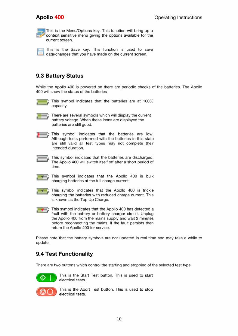
Apollo 400 Operating Instructions
10
This is the MenuOptions key This function will bring up a
context sensitive menu giving the options available for the
current screen
This is the Save key This function is used to save
datachanges that you have made on the current screen
93 Battery Status
While the Apollo 400 is powered on there are periodic checks of the batteries The Apollo
400 will show the status of the batteries
This symbol indicates that the batteries are at 100
capacity
There are several symbols which will display the current
battery voltage When these icons are displayed the
batteries are still good
This symbol indicates that the batteries are low
Although tests performed with the batteries in this state
are still valid all test types may not complete their
intended duration
This symbol indicates that the batteries are discharged
The Apollo 400 will switch itself off after a short period of
time
This symbol indicates that the Apollo 400 is bulk
charging batteries at the full charge current
This symbol indicates that the Apollo 400 is trickle
charging the batteries with reduced charge current This
is known as the Top Up Charge
This symbol indicates that the Apollo 400 has detected a
fault with the battery or battery charger circuit Unplug
the Apollo 400 from the mains supply and wait 2 minutes
before reconnecting the mains If the fault persists then
return the Apollo 400 for service Please note that the battery symbols are not updated in real time and may take a while to
update
94 Test Functionality
There are two buttons which control the starting and stopping of the selected test type
This is the Start Test button This is used to start
electrical tests
This is the Abort Test button This is used to stop
electrical tests
Apollo 400 Operating Instructions
11
10 Main Menu
101 View Saved Data This will allow you to view any data that you have saved in the Apollo 400 By selecting this
icon in the Main Menu you can view a list of all saved Asset IDs by site and location
Use the arrow keys to scroll up and down
This is the Accept function This will open the selected
record
This button allows you to filter records to give a
customised view Select the filters you wish to apply and
press lsquoAcceptrsquo
Once in the record you will be given a list of items under that record such as PAT results and
JPEG images Press Accept to open
This button allows you to delete the selectde record
When viewing a PAT_results record the Menu icon will become available so that you can
view results or print labels When viewing a saved Health amp Safety Form you can edit the report and then save the
changes This will create a new time and date stamped report as well as saving the original
This is the MenuOptions key This function will bring up a
context sensitive menu giving the options available for the
current screen
102 User Options
Apollo 400 has one default user account set up as admin who will have full access to the
product You can add one additional user account to the Apollo 400
This is where you can set up new edit and delete the user account The user can alter their
own screen power save time Auto power down background image avatar and power on
screen and press Save to apply
Use this button to Change User You can then select the
User name to change the current user of the tester
This User Information menu allows users to view their
user type (Expert or Novice)
This is the New User button Here you can set up a new
user account by adding a username and pressing lsquoSave
You can then select their name from the dropdown in the
User Information screen select the type of user (Expert or
Novice
Apollo 400 Operating Instructions
12
This is the Delete User button It will delete whichever
user is currently selected in the lsquoUsernamersquo dropdown
Please note that the admin user cannot be deleted
Press this button to Save changes and return to the
previous screen
103 Bluetooth Setup
Select this icon to setup your Bluetooth accessories to work with the Apollo 400 Switch on
the Bluetooth device you wish to pair with and ensure it is discoverable
This will Bluetooth Search button will search the area for
Bluetooth discoverable devices and return to the previous
menu You can then use the arrow keys to select the
correct Bluetooth ID from the dropdowns for your Bar
Code Scanner Printer or Mobile Device Press lsquoSaversquo
once complete
Press this button to save changes and return to the
previous screen
104 Automatic Test Sequence Editor (PAT Edit)
Although the Apollo 400 comes with a number of pre-defined test sequences you can modify
existing or create new test sequences of their own
From the Menu function key select one of the following options using the arrow keys and the
Accept button
This is the MenuOptions key This function will bring up a
context sensitive menu giving the options available for the
current screen
This is the Accept function This will open the selected
option
Edit Edits the highlighted sequence
Copy Makes a copy of the highlighted test
sequence
Delete Deletes the highlighted test sequence
Add New Adds a new test sequence to the bottom of the
list
Insert New Adds a new test below the highlighted test
sequence
Apollo 400 Operating Instructions
13
When editing a test sequence the following functions are available
This is the Add Test function This will add a new test
directly under the currently selected test
This is the Delete Test function This will delete the
highlighted test from the test sequence
This is the Edit Test function This will edit the
highlighted test
105 Download
Downloading to PATGuard 3
You can download the data from your Apollo to PATGuard 3 software
In the Download menu select To PATGuard in the Download from Apollo dropdown
This button is a way of downloading all data from Apollo
You then need to select one of 2 options from the using dropdown
USB-PC cable
Connect the USB download cable to the USB type B port on the Apollo 400 and to a USB
port on your PC Press Save
Instructions for how to import this download into PATGuard 3 can be found in the PATGuard
3 help files
Bluetooth to Mobile Device
You will need to have a Bluetooth enabled mobile device configured with the Apollo 400 to
use this method See 103 Bluetooth Setup
NB The Apollo 400 does not have the option to download to flash disk
106 Set Date and Time
You can change the date and time in this menu using the arrow keys and number keys
Press this button to save changes and return to the
previous screen
107 Memory
This section will allow you to view how much memory space you have used and how much
is left
This is the Restore button Selecting this will allow you to
clear memory or reset factory settings Select what you
Apollo 400 Operating Instructions
14
would like to restore by pressing the Enter button
Press this button to save changes and return to the
previous screen
11 Portable Appliance Testing
111 Automatic Test Sequence
The Apollo 400 comes with a number of pre-defined test sequences (see Factory Set Test
Sequences) These test sequences can include any combination of electrical tests These
test sequences are performed on equipment to ensure that it meets the safety requirements
outlined in the IET Code of Practice for In-service Inspection and Testing of Electrical
Equipment
1111 Entering Asset Details
Asset ID This is unique identifier for the equipment under
test This can be entered using the keypad or a
barcode scanner (see 103 Bluetooth Setup)
Test
Sequence This is the name of the pre-defined test sequence
which will be performed on the equipment
Site This is the site where the equipment is located
You can choose a site from the dropdown using
the arrow keys or enter a new one
Location This is the location within the site where the
equipment is You can choose a location from the
dropdown using the arrow keys or enter a new
one
Retest Period
(Visual) This is the period in months in which the
equipment should be re-inspected
Retest Period
(Full) This is the period in months in which the
equipment should be re-tested
1112 The Formal Visual Inspection
All pre-set test sequences start with a Visual Inspection
This is the Pass Icon
This is the Fail icon
Apollo 400 Operating Instructions
15
This means that the inspection is not applicable to the
EUT
Pass
All
Pressing the Pass All button will apply a pass to all
relevant inspections and move onto the next test
1113 The Electrical Tests
The Apollo 400 has probe detection that will automatically flag up if you do not have the
correct probe configuration for the test you are trying to perform
During the tests you can see the test duration limit and result on screen see 91 Screen
Layout
Should any test with the sequence fail the sequence will be aborted and you will presented
with the Notes screen by default but this can be changed see 115 PAT Settings
1114 Printing a Label
If you have a TnT Bluetooth printer configured with the Apollo 400 you can print a label after
each test
See 103 Bluetooth Settings to set up a printer
Press this button to go to the print screen and then
again to print a label
This is the Tools function This function allows you to
configure which pre-configured label printer to use
112 Manual Test Interface
The Apollo 400 allows direct access to all of the electrical tests through Manual Mode
Within each test there are a number of function key options
This is the Tools function This function allows you to
configure the test current test type this includes - test duration - test passfail limit
- test typeconnection
Always ensure that you have selected the correct test
connection method in the test for the probe
connections made
Please refer to the Test Functions section for specific information about each test type
Apollo 400 Operating Instructions
16
113 Test Functions
Earth Continuity
Always ensure that the circuit under test is electrically
isolated
Note that measurements can be adversely affected by
parallel resistances of additional circuits or by
transient currents
Connecting a test probe to a hazardous voltage when
a point to point measurement is active will result in
that voltage being present on the other test probe This test is applicable to Class I equipment This test will measure one of the following
resistance between the protective earth terminal in the EUT mains plug and the point
at which a single test probe is applied ndash CLI EUT Continuity
resistance between two test probes ndash Point to Point Continuity resistance between the protective earth terminal in an IEC lead mains plug and the
protective earth terminal in the IEC connector ndash IEC Continuity to ensure that the connection is satisfactory and of sufficiently low resistance The
measurement will be displayed in Ohms There are three possible connection methods for the Earth Continuity test
CLI EUT Continuity
The test is performed between the red
test terminal and the EUT test socket
Point to Point Continuity
This test is performed between the red
test terminal and the black test
terminal Additional test lead is
required
IEC Continuity
The test is performed between the EUT
test socket and the IEC test socket
Always ensure that you have selected the appropriate
test type for the probe connections
Apollo 400 Operating Instructions
17
Selecting test type
In manual PAT test mode the earth continuity test can be switched between a Class I EUT
continuity test and a point to point continuity test as follows
Select Class I Continuity (1) and press the setup key (F3) In the Test Type field select EUT
Continuity Test or Point to Point Continuity Test
During automatic sequences the test type will be as per the test type programmed in the
test sequence Once the correct connections have been made for the selected test type press
the Start button The test will continue until it times out If we wish to abort the current test
press the Stop button Tests on IEC leads CLI EUTs can be performed using a current of
+200mA andor -200mA Tests performed in point to point mode are always performed
using a current +200mA test The direction of the test current can be reversed by switching
the test probes at the point of connection to the appliancecircuit under test
Nulling out the earth continuity test lead(s) resistance
For a more accurate earth continuity measurement the resistance of the test lead(s) can be
zeroed out The feature can be used with both the EUT Continuity and Point to Point
measurement modes
The null facility remains active even if the Apollo 400 is powered off until the feature is
deactivated by pressing the null key again or the Test Type is changed eg if a pair of test
leads are nulled for point to point measurement the null will be deactivated if the Test Type
is changed to EUT Continuity test
Nulling a single test lead
In the manual PAT screen press the setup key (F3) and change the Test Type to EUT
Continuity Test Press save (F4) Connect the earth continuity test lead to the earth continuity
test socket and connect the probe tip to the earth pin of the EUT socket Press Null (F4) to
measure and stored the test lead resistance When the null feature is active the Null icon will
appear on the display
Nulling both test leads
In the manual PAT screen press the setup key (F3) and change the Test Type to Point to
Point Continuity Test Press save (F4) Connect both earth continuity test leads to the earth
continuity test sockets and connect the probe tips together using the supplied alligator clips
Press Null (F4) to measure and stored the test lead resistance When the null feature is active
the Null icon will appear on the display
Insulation Resistance
Always ensure that the circuit under test is electrically
isolated
Connecting a test probe to a hazardous voltage when
a point to point measurement is active will result in
that voltage being present on the other test probe This test is applicable to Class I and Class II equipment This test will measure one of the
following
insulation resistance between live circuits and the protective earth circuit in the EUT
ndash Class I IEC lead insulation test insulation resistance between live circuits and a test probe applied to the EUT ndash
Class II insulation test
Apollo 400 Operating Instructions
18
insulation resistance between two test probes ndash Point to Point Insulation
to ensure that the test points are adequately insulated from one another The measurement
is displayed in MOhms There are three possible connection methods for the Insulation test
CLI and IEC Insulation
The test is performed between the EUT
test socket live and neutral and the EUT
test socket earth pin For IEC leads the other end of the lead
should be connected into the IEC test
socket
CLII Insulation
The test is performed between the EUT
test socket live and neutral and Red
test terminal
Point to Point Insulation
The test is performed between the Red
and Black test terminals both the
continuity test leads are required for
this test Additional test lead is
required
Always ensure that you have selected the correct test
connection method in the test for the probe
connections made
Ensure that the appliance mains switch is in the ON
position
During this test 250V or 500V DC is applied between
the two connections points The 500V DC potential
will be present across the two probe tips during a
Point to Point test
Selecting test type
In manual PAT test mode the insulation test can be switched between a 250V EUT
Insulation test 500V EUT Insulation test 250V Point to Point Insulation test or 500V Point to
Point Insulation test as follows
Apollo 400 Operating Instructions
19
Select Insulation Resistance (2) and press the setup key (F3) In the Test Type field select
the required test
During automatic sequences the test type will be as per the test type programmed in the
test sequence
In manual mode once the correct connections have been made for the selected test type
press the Start button in automatic mode the test will proceed automatically The test will
continue until it times out If we wish to abort the current test press the Stop button The
measurement will be displayed in Mega Ohms If an EUT fails the Insulation test then this may be because of internal filtering or an MOV
Retry the test at 250V or substitute the Insulation test with a Protective Conductor or Touch
Current test
Substitute Leakage
This test is applicable to Class I and Class II equipment This test is used to verify that the
leakage between the mains conductors of the EUT to the EUT earth pin or conductive
accessible surface of the enclosure is to a satisfactory low level There are two possible connection methods for the Substitute Leakage test
CLI and IEC Substitute Leakage
The test is performed between the EUT
test socket live and neutral and the EUT
socket earth pin
For IEC leads the other end of the lead
should be connected into the IEC test
socket
CLII Substitute Leakage The test is performed between the EUT
socket live and neutral and Red test
terminal
During this test 40V AC is applied between the earth pin and both the live and neutral
pins of the appliance mains supply plug In manual mode once the correct connections have been made for the selected test type
press the Start button in automatic mode the test will proceed automatically The test will
continue until it times out If we wish to abort the current test press the Stop button The
measurement will be displayed in milli Amps
This test can prove useful in situations where neither conventional insulation nor flash tests
are acceptable methods of testing the insulation of the appliance
Please note that values for substitute leakage may differ substantially from that of
Apollo 400 Operating Instructions
20
conventional earth leakage tests because of the way that the test is performed (eg it will be
affected by the presence of Neutral-to-Earth suppression capacitors)
Protective Earth (PE) Conductor Current
Always test the earth continuity and insulation
resistance before performing a PE Conductor Current
test
Always check that an appliance with moving parts (eg
an electric drill) is safely mounted to avoid risk of
damage to equipment or personnel
Avoid prolonged repeated use at full load (16A) and
excessive test duration as this may reduce the life of the
unit
Always ensure that appliance and leads which include
RCD protection that the RCD is reset at the beginning
of the test Failure to do so may result in incorrect
measurements being recorded
This test is applicable on Class I
Equipment The Apollo 400 should be connected to
a mains supply The EUT should be
connected into the EUT test socket In manual mode once the correct
connections have been made for the
selected test type press
the Start button in automatic mode the
test will proceed automatically
The test will continue until it times out If we wish to abort the current test press
the Stop button The measurement will be displayed in mA Should the test measurement over range then the test will be aborted immediately and a fail
will be logged
Touch Current
Warning Always test the insulation resistance before
performing a Touch Current test
Warning Always check that an appliance with moving
parts (eg an electric drill) is safely mounted to avoid
risk of damage to equipment or personnel
Attention Avoid prolonged repeated use at full load
(16A) and excessive test duration as this may reduce the
life of the unit
Always ensure that appliance and leads which include
RCD protection that the RCD is reset at the beginning
of the test Failure to do so may result in incorrect
measurements being recorded
Apollo 400 Operating Instructions
21
This test is applicable on Class I and
Class II Equipment The Apollo 400 should be connected to
a mains supply The EUT should be
connected into the EUT socket the red
test terminal should be connected to
point at which the leakage measurement
is required
In manual mode once the correct connections have been made for the selected test type
press the Start button in automatic mode the test will proceed automatically The test will
continue until it times out If we wish to abort the current test press the Stop button The
measurement will be displayed in milli Amps Should the test measurement over range then the test will be aborted immediately and a fail
will be logged
RCD Trip Time
Voltages between the protective conductor and earth
may influence measurements This test will pass a sinusoidal current of 30mA between the EUT socket and the IEC socket
and measure the time it takes for the in-line RCD to trip
Remove all other connections before performing an
RCD test
The Apollo 400 should be connected to
a mains supply The RCD should be
plugged into the EUT test socket and a
connection should be made from the
RCD mains output to the IEC test
socket
Once the correct connections have been made for the selected test type press
the Start button The RCD will be powered and you will be prompted to reset the RCD
When you have reset the RCD the Apollo 400 will count down and then perform the RCD
test the RCD trip time will be displayed The measurement will be displayed in milli seconds
IEC Lead Polarity
The IEC lead input is a test socket and is not intended
to be connected directly to mains Do not connect this
input to the mains supply
The Polarity test checks the wiring
polarity of an IEC lead the IEC should
be plugged into both the EUT and IEC
test sockets
This test can be used to test the wiring polarity of extension leads by plugging the supplied
test IEC lead into the end of the extension lead to complete the circuit to the IEC tests
socket In the automatic sequence editor the Polarity can be added to sequence In the manual
mode the polarity test is already part of a pre-defined test sequence which includes an Earth
Continuity test an Insulation test and the Polarity test
External Leakage Adaptors
Apollo 400 Operating Instructions
22
While using an External Leakage Adaptor the mains
supply will be connected to the EUT through the
adaptor
Ensure that when tests are performed using the
external Leakage Adaptor that the Earth Reverse
option is set to Off
The External Leakage Adaptor test
function is intended to used in
conjunction with the one of Seawards
external leakage adaptors Connect the
external leakage adaptor into the Red
test terminal connect the Earth
Continuity probe into the Black test
terminal
Connect the mains supply and the EUT
to the external leakage adaptor
Note that connecting both the EUT and mains supply to the external leakage adaptor will
connect the mains supply to the EUT
114 Checkbox Verification
A checkbox for the Apollo 400 is available as an optional accessory This can be used to
verify that the Apollo 400 test functions are working correctly When selecting the Checkbox
function follow the onscreen instructions
The Checkbox function will perform a number of
electrical tests Ensure that the onscreen instructions
are followed and that you do not touch the checkbox
during the active tests
12 Updating your Firmware
1 Go to wwwseawardcoukfirmware and save the latest Apollo 400 firmware file on
your PC
2 Power on the unit whilst holding down the F1 button
3 Press F2 to update via PC
4 Follow the onscreen instructions
5 Restart the unit
You can check the firmware version of your tester by
pressing this icon in the Home screen
Apollo 400 Operating Instructions
23
13 Electrical Specification
Earth Continuity
Output Current (Load 2Ω)
Test Voltage (oc)
Measuring Range
Display Range
Resolution Operating Error
Number of tests as per IEC61557-
4
+- 200mA DC with ZAP
gt 4VDC
005 Ωndash 1999 Ω
001 Ω ndash 1999 Ω
001 Ω +-5 + 4 counts
approx 1500
Insulation Test
Test Voltages
Test Current
Test Voltage Accuracy
Measuring Range
Display Range
Resolution Operating Error ( lt 10MΩ ) ( gt 10MΩ )
Number of tests as per IEC61557-
2
500V and 250V DC
1mA minimum for a load of
1kohmvolt lt2mA into sc
+20 -0
010M Ω to 1999M Ω
000M Ω to 1999M Ω
001M Ω +-5 +5 counts +-10 +5 counts approx 1500
Subsitute Leakage Test
Test Voltages
Measuring Range
Display Range
Resolution Operating Error
gt25Vac lt50Vac
020mA to 1999mA
000mA to 1999mA
001mA +-10 +2 digits
Protective Conductor Current
Test Voltage
Display Range
Measurement Range
Resolution
Operating Error
Frequency Response
Supply Voltage maximum
load current 16A
001mA to 1999mA
025mA to 1999mA
001mA
+-5 of reading +- 3 digits
40Hz to 25 kHz
Touch Current
Test Voltage
Display Range
Measurement Range
Resolution
Operating Error
Frequency Response
Supply Voltage maximum
load current 16A
000mA to 350mA
010mA to 350mA
001mA
+-5 of reading +- 2 digits
DC to 25 kHz
Apollo 400 Operating Instructions
24
Load PowerCurrent
Test Voltage
Display Range
Measurement Range
Resolution
Operating Error
Supply Voltage maximum
load current 16A
000 - 1600A
050 - 1600A
001A
+-10 of reading +- 5 digits
Lead Test
Test Voltage
Test 5V DC nominal
Live Neutral checks for oc
sc and crossed
Power Socket Test
Input voltage range
195V ndash 253V AC
Indicates configuration of
voltage potential-
Line potential phase to earth
Line potential phase to neutral
Line potential neutral to earth
RCD Test
Test Voltage
Test Current
Test Current Accuracy
Display Range
Measuring Range
Resolution
Operating Error
230V +10 -15
30mA 150mA rms sinusoidal
30mA -10 +0 150mA +10 -0
0 ndash 2000ms
1ms ndash 2000ms
1ms plusmn1ms
External Leakage
Test Voltage
Display Range
Measuring Range
Resolution
Operating Error
Connected to External
Adapter
0mA - 999mA
025mA - 999mA
001mA +-5 of reading +-2 digits
Apollo 400 Operating Instructions
25
14 Useful Information - 141 Factory Set Test Sequences
Test
Visual Earth Continuity Insulation PE Conductor
Current Touch Current
Substitute
Leakage Wiring
RCD
Trip
Time
Name
Duration
(s)
Limit
(ΩΩ) Duration (s) Voltage
Limit
(MΩΩ)
Duration
(s)
Limit
(mA)
Duration
(s)
Limit
(mA)
Duration
(s)
Limit
(mA)
Limit
(ms)
PortableHandheldIT CLI Yes 5 01 2 500 1
PortableHandheldIT CLII Yes 2 500 2
Fixed Appliance CLI Yes 2 01 5 500 1
Fixed Appliance CLII Yes 5 500 2
IEC Lead 2m Yes 5 02 2 500 1 Yes
13A 5m Surge Protected Lead Yes 5 02 2 250 1 Yes
13A 25m Ext Lead 30mA RCD Yes 5 05 5 08 30
Portable CLI PE Current Yes 5 05 2 250 1 5 08
Portable CLII Touch Current Yes 2 250 2 5 03
IT Equip CLI PE Current Yes 5 01 2 250 1 5 35
IT Equip CLII T ouch Current Yes 2 250 5 03
13A 6m Mains Lead Yes 5 02 2 500 1 Yes
13A 12m Mains Lead Yes 5 03 2 500 1 Yes
13A 24m Mains Lead Yes 5 05 2 500 1 Yes
MovStat CLI 500V Insulation Yes 5 01 2 500 1
MovStat CLII 500V Insulation Yes 2 500 2
MovStat CLI PE Current Yes 5 01 2 250 1 5 35
MovStat CLII Touch Current Yes 2 250 2 5 35
110V HandheldPortable CLI Yes 5 01 2 500 1 2 08
110V HandheldPortable CLII Yes 2 500 2 2 03
110V MovableStationary CLI Yes 5 01 2 500 1 2 35
110V MovableStationary CLII Yes 2 500 2 2 03
110V 25m Lead
RpeampInsulation Yes 5 05 2 500 1
Visual Only Yes
Apollo 400 Operating Instructions
26
142 Other Information
Parameter Default Min Max
Earth Continuity PF limit (Ω) 01 001 1999
Earth Continuity Duration (s) 5 2 30
Insulation Resistance PF limit (MΩ) 1 001 1999
Insulation Resistance Duration (s) 5 2 30
Substitute Leakage PF limit (mA) 075 025 15
Substitute Leakage Duration (s) 5 2 30
IEC Cord Earth Continuity PF limit
(ohms) 01 001 5
IEC Cord Insulation PF limit (MΩ) 1 001 1999
Touch Current PF limit (mA) 025 025 350
Touch Current Duration (s) 5 2 30
PE Conductor Current PF limit (mA) 075 025 1999
PE Conductor Current Duration (s) 5 2 30
External Adapter Continuity (Ω) 01 001 5
External Adapter Leakage (mA) 075 025 999
External Adapter Duration (s) 5 2 30
RCD 30mA trip time (ms) 200 1 2000
RCD 150mA trip time (ms) 40 1 40
Number of tests in a test sequence 1 60
Characters in a test sequence name 1 30
Characters in a User Test name 1 15
Characters in a User Test Unit 15
Total number of Test Sequences 25
Test Results (typical) 2000
Sites 50
Characters in Site name 1 15
Locations 50
Characters in Location name 1 15
Users (including admin) 2
Characters in User name 1 15
Comments List 50
Characters in Comment 25
Characters in Asset ID 1 15
Apollo 400 Operating Instructions
27
15 Environmental Conditions
The Apollo 400 has been designed to perform tests and measurements in a dry environment
Maximum barometric elevation for making measurements is 2000M
Pollution degree 2 according to IEC 60529
Electromagnetic compatibility (EMC) Interference immunity and emitted interference
conforming to IEC 61326-1
Operating temperature range of 0 to 40 degrees C without moisture condensation
Operating Altitude 0 to 2000 metres
16 Maintenance
161 Charging the battery pack
The battery pack will be charged whenever the Apollo 400 is connected to the mains supply
regardless of whether it is switched on or off
The typical charging current is set to 500mA but this may vary as the instrument also
includes pre-charge and top up charge modes
When no tests are being performed the battery pack will be fully re-charged after 7 hours
162 Securing the Apollo 400
Under certain conditions safe operation of the Apollo 400 can no longer be assumed
Visible damage of the instrument case
Incorrect measurement results
Recognisable abuse to the instrument due to prolonged storage under improper conditions
Recognisable abuse to the instrument due to extraordinary transportation stress
In these case the Apollo 400 should be immediately switched off disconnected from any test
and measurement function and secured to prevent any further use
163 Cleaning the Apollo 400
Clean the external case of the Apollo 400 with a dry clean cloth
Avoid using solvents and abrasive scouring agents to clean the external case of the Apollo
400
Apollo 400 Operating Instructions
28
164 Replacing the battery pack
Before opening the Apollo 400 battery compartment
ensure that all test leads and accessories are
disconnected
Power off the instrument
Disconnect all test leads and accessories
Position the instrument face down and remove the screw holding the battery compartment
cover in place
Remove the battery compartment cover
Remove the battery pack from the compartment and unplug the 4 way connector
Connect the 4 way connector of the new battery to the 4 way header in the battery
compartment put the battery pack into the compartment
Relocate the battery compartment cover and fasten in position with the battery compartment
screw
ONLY USE A REPLACEMENT BATTERY PACK THAT HAS BEEN SUPPLIED BY SEAWARD
OR A SEAWARD APPROVED DISTRIBUTOR
17 Support
The Apollo 400 must be registered with Seaward before support will be made available For Technical Support contact Tel (+44) 191 587 8718
For help or advice on Service and Calibration contact
CalibrationHouse Seaward Electronic Bracken Hill South West Industrial Estate Peterlee Co Durham SR8 2SW England Tel (+44) 191 5878739 (+44) 191 5878737 Email serviceseawardcouk
Calibration House is part of the Seaward Group
Apollo 400 Operating Instructions
29
171 Register your product here-
wwwseawardcouk 172 Calibration Services-
wwwcalibrationhousecouk Bracken Hill South West Industrial Estate Peterlee County Durham SR8 2SW Co Durham SR8 2SW England Tel (+44) 191 5863511 Some icons provided by Fat Cow (httpwwwfatcowcomfree-icons) Based in part on the work of the Qwt project (httpqwtsfnet)
Apollo 400A simple no-nonsense PAT tester with fast data entry and storage for up to 2000appliance records
Key Featuresn High definition colour displayn Store 2000 appliance recordsn Remote data transfer from field to office n Bluetooth connectivity
Electrical Test Functionsn Low current earth continuity test guaranteeing accurate measurement n Point to point testing (earth continuity and insulation resistance)n Insulation resistancen IEC lead testn Protective conductor currentn Touch currentn Load powercurrentn Alternative leakage currentn RCD testn Power socket test
Ideal Forn Electrical Contractorsn Facilities Managersn Operations Managers
Apollo 400 offers simple electrical safety testing with straightforward data entryusing the intuitive QWERTY keypad
A comprehensive range of electrical safety tests ensure compliance with theIET 4th Edition Code of Practice whilst remote data transfer and USB downloadmakes data management easy and efficient
The Apollo 400 is ideal for mid-volume PAT testing where detailed records arerequired
Streamline the PAT testing process further by using the Apollo 400 with acompatible label printer barcode scanner and PATGuard 3 software
wwwseawardcoukapollo400
Tel +44 (0) 191 587 8741Email salesseawardcouk
Requires optional accessory (part number 380A983)
Straightforward PAT testing with simple data managementApollo 400 offers a comprehensive suite of electrical safetytests to enable any workplace appliance to be tested including3-phase equipment fixed appliances and RCDs
The QWERTY keypad enables asset information to be entered quicklyand easily while a large colour display with an intuitive menu structure makesthe Apollo 400 simple to grasp Lightweight and small in size with battery or mainspower modes the Apollo 400 is good to go in seconds allowing more appliances to betested without downtime for boot-up or a battery re-charge
Superb software for total traceabilityApollo 400 has an internal memory capable of storing up to 2000electrical test records Its compatibility with Seawardrsquos PATGuard 3software means that complete test records are easily managed ona PC
Transfer data to the PC remotely using the Bluetooth function anda smartphone or download the results via a USB cable directly toa PC Once downloaded to PATGuard 3 it is easy to keep track ofthe history of test and inspections as well as produce reportscertificates and invoices ndash offering total peace of mind and quickereasier management of scheduling inspections and tests
Download a free trial at wwwseawardcoukpg3trial
wwwseawardcoukapollo400
Tel +44 (0) 191 587 8741Email salesseawardcouk
additional accessory required for point to point testing
u Accessory BundlesThe Apollo 400 is available to buy with a selectionof optional accessory bundles to help you get themost out of your tester
Apollo 400 is supplied as standard with a UKAScalibration certificate and a 2 yearmanufacturerrsquos warranty (subject to terms andconditions)
Greater efficiency through useful accessoriesAs with many Seaward PAT testers the Apollo 400 is compatible with arange of printers and barcode scanners further speeding up the processof asset recognition testing and labelling
Also available in this range
A multi-tasking and fully customisable PAT with additionalhealth and safety features and on-board camera forunrivalled record keeping
Apollo 600 includes a universal risk assessment tool andthe ability to store up to 50000 appliance records plus2000 images - providing visual evidence of testenvironments perfect for advanced record-keeping inorganisations with high-volume workplace test andinspection routines
Apollo 600Multi-tasking PAT tester with on-board camera
wwwseawardcoukapollo400
Tel +44 (0) 191 587 8741Email salesseawardcouk
A powerful PAT tester with a built-in PAT retest calculatorand flexible user-configurable sequences for recordingany non-electrical workplace test or inspection
The ability to customise a number of settings and a largememory to store up to 10000 appliance records makesthe Apollo 500 a versatile and dependable tool for highvolume PAT testing
Apollo 500A fast amp fully customisable and versatile PAT tester
Optional accessory bundles available Part Number
Elite Bundle n Test n Tag Elite 2 rugged portable printer
n Test n Tag printer labels x 4
n Bluetooth barcode scanner
n Apollo kit carry case
n 110V adapter
Includes Apollo 400 tester
380A978
Elite Bundle +Software
PLUS PATGuard 3 software 1yr licence 380A979
Pro Bundle n Test n Tag Pro lightweight portable printer
n Test n Tag printer labels x 4
n Bluetooth barcode scanner
n Apollo kit carry case
n 110V adapter
Includes Apollo 400 tester
380A980
Pro Bundle +Software PLUS PATGuard 3 software 1yr licence 380A981
wwwseawardcoukapollo400
Tel +44 (0) 191 587 8741Email salesseawardcouk
Apollo 400 Apollo 500 Apollo 600
General Features
Battery amp mains powered n n n
Colour Screen amp QWERTY keypad n n n
Large internal memory 2000 records 10000 records 50000 records
Scanner amp printer compatible n n n
Password controlled user accounts n n
Set up multiple user accounts with varyinglevels of privileges
n n
Clone facility to set up multiple testers n n
Checkbox supplied as standard n n
On-board user manual n n
Test amp InspectionFeatures
Auto-increment asset ID n n
PAT Setup option to allow for custom menus n n
Enter asset description after test usingkeypad or barcode scanner
n n n
Comprehensive electrical safety test features n n n
Point to point measurement (Rpe amp IR)
n
(optional
accessory
required)
n n
User configurable electrical testvisualinspection sequences 25 100 100
User set sites amp locations 50 100 100
Risk based retest period calculator n n
User definable comments lines against testrecords
n n
Configurable checklists for any workplacetest or inspection (user tests)
n n
On-board camera n
Universal risk assessment n
Health amp safety certificates n
Data Transfer
Bluetooth connectivity n n n
Barcode scanner connectivity n n n
Print Pass amp Fail labels n n n
Add your company logo to labels n n
Select from various label formats to print n n
Remote data transfer via mobile device n
(Android only)
n
(Android only)
n
(Android and iOS)
Download to PC via USB cable n n n
Filter results to be downloaded n n
Upload previous results to tester for retest n n
Data transfer via USB flash drive n
Apollo Series Comparison Chart
PAT TESTS
Earth ContinuityTest Current +- 200mA DC Display Range 001 ndash 1999ΩPass Value User Defined
Insulation ResistanceTest Voltage 500V 250VDC 1mA nominalDisplay Range 001MΩ - 1999MΩPass Value User Defined
IEC Lead TestTest Voltage 5VAC nominalTest Live Neutral Checks for oc sc and crossed
Protective Conductor CurrentLoad
Test Voltage Supply voltage maximum load current 16A Display Ranges 001mA to 1999mA Pass Value User Defined
Touch Current
Test Voltage Supply Voltage maximum load current 16ADisplay Range 000 ndash 350mA Pass Value User defined
Load PowerCurrent
Test Voltage Supply Voltage maximum load current 16ATest Duration Programmable up to a maximum of 255s depending on load ie max duration is reduced for high loadsDisplay Range 000kVA ndash 400kVA 000A ndash 1600A
Alternative Leakage Current
Test Voltages gt25VAC lt50VAC Display Range 000mA to 1999mAPass Value User Defined
RCD Test
Test Voltage 230V +10 -15Test Current 30mA 150mA rms sinusoidalDisplay Range 0ms - 2000ms (30mA) 0-40ms (150mA)Test Method Internal isolation to avoid tripping distribution board RCD
Power Socket Test
Voltage Range 207V ndash 253VACIndicates configuration of voltage potential-Line potential phase to earthLine potential phase to neutralLine potential neutral to earth
General
Memory Size 2000 recordsWeight 15kgDimensions 230mm x 150mm x 100mmPower Source Mains or rechargeable battery pack
Standard Accessories (supplied with Apollo 400)30 day free trial of PATGuard 3 software 1x red test lead and probe with crocodile clip05m IEC leadMains power leadUSB download cableQuick start guideUKAS calibration certificate
Optional Accessories Test n Tag Elite 2 Bluetooth printer with roll of small labels (339A995)Test n Tag Pro Bluetooth printer with roll of small labels (339A987)Roll of small labels (approx 350 off 52 x 25mm labels) (339A947)Additional black test lead and probe with crocodile clip (for point to point testing) (380A983)Bluetooth barcode scanner (339A923)110V test adaptor (270A076)110V to IEC adapter (344A050)Apollo checkbox (380A953)3 Phase Leakage Adaptor 5 Star 16A (391A920)3 Phase Leakage Adaptor 5 Star 32A (391A910)3 Phase Adapter Delta 4 pin 16A 415V (for Rpe amp IR) (209A910)3 Phase Adapter Star 5 pin 16A 415V (for Rpe amp IR) (209A911)3 Phase Adapter Delta 4 pin 32A 415V (for Rpe amp IR) (209A912)3 Phase Adapter Star 5 pin 32A 415V (for Rpe amp IR) (209A913)Professional Seaward kit bag (71G109)Apollo carry case (380A952)PATGuard 3 software ndash download 30 day free trial atwwwseawardcoukpg3trial
Part NumbersApollo 400 standard package 380A920Apollo 400 with Elite accessory bundle 380A978Apollo 400 with Elite accessory bundle amp PATGuard 3 one year licence380A979Apollo 400 with Pro accessory bundle 380A980Apollo 400 with Pro accessory bundle amp PATGuard 3 one year licence380A981
TrainingSeaward offer a range of PAT testing courses including City amp GuildsGo to wwwseawardcouktraining for more information
Services2 year warranty (subject to terms and conditions available atwwwseawardcoukwarranty24)Service amp Calibration by CalibrationhouseGo to wwwcalibrationhousecom for more information
Technical Specifications
Part of
Rev 12
wwwseawardcoukapollo400
Tel +44 (0) 191 587 8741Email salesseawardcouk
Apollo 400 Operating Instructions
15
This means that the inspection is not applicable to the
EUT
Pass
All
Pressing the Pass All button will apply a pass to all
relevant inspections and move onto the next test
1113 The Electrical Tests
The Apollo 400 has probe detection that will automatically flag up if you do not have the
correct probe configuration for the test you are trying to perform
During the tests you can see the test duration limit and result on screen see 91 Screen
Layout
Should any test with the sequence fail the sequence will be aborted and you will presented
with the Notes screen by default but this can be changed see 115 PAT Settings
1114 Printing a Label
If you have a TnT Bluetooth printer configured with the Apollo 400 you can print a label after
each test
See 103 Bluetooth Settings to set up a printer
Press this button to go to the print screen and then
again to print a label
This is the Tools function This function allows you to
configure which pre-configured label printer to use
112 Manual Test Interface
The Apollo 400 allows direct access to all of the electrical tests through Manual Mode
Within each test there are a number of function key options
This is the Tools function This function allows you to
configure the test current test type this includes - test duration - test passfail limit
- test typeconnection
Always ensure that you have selected the correct test
connection method in the test for the probe
connections made
Please refer to the Test Functions section for specific information about each test type
Apollo 400 Operating Instructions
16
113 Test Functions
Earth Continuity
Always ensure that the circuit under test is electrically
isolated
Note that measurements can be adversely affected by
parallel resistances of additional circuits or by
transient currents
Connecting a test probe to a hazardous voltage when
a point to point measurement is active will result in
that voltage being present on the other test probe This test is applicable to Class I equipment This test will measure one of the following
resistance between the protective earth terminal in the EUT mains plug and the point
at which a single test probe is applied ndash CLI EUT Continuity
resistance between two test probes ndash Point to Point Continuity resistance between the protective earth terminal in an IEC lead mains plug and the
protective earth terminal in the IEC connector ndash IEC Continuity to ensure that the connection is satisfactory and of sufficiently low resistance The
measurement will be displayed in Ohms There are three possible connection methods for the Earth Continuity test
CLI EUT Continuity
The test is performed between the red
test terminal and the EUT test socket
Point to Point Continuity
This test is performed between the red
test terminal and the black test
terminal Additional test lead is
required
IEC Continuity
The test is performed between the EUT
test socket and the IEC test socket
Always ensure that you have selected the appropriate
test type for the probe connections
Apollo 400 Operating Instructions
17
Selecting test type
In manual PAT test mode the earth continuity test can be switched between a Class I EUT
continuity test and a point to point continuity test as follows
Select Class I Continuity (1) and press the setup key (F3) In the Test Type field select EUT
Continuity Test or Point to Point Continuity Test
During automatic sequences the test type will be as per the test type programmed in the
test sequence Once the correct connections have been made for the selected test type press
the Start button The test will continue until it times out If we wish to abort the current test
press the Stop button Tests on IEC leads CLI EUTs can be performed using a current of
+200mA andor -200mA Tests performed in point to point mode are always performed
using a current +200mA test The direction of the test current can be reversed by switching
the test probes at the point of connection to the appliancecircuit under test
Nulling out the earth continuity test lead(s) resistance
For a more accurate earth continuity measurement the resistance of the test lead(s) can be
zeroed out The feature can be used with both the EUT Continuity and Point to Point
measurement modes
The null facility remains active even if the Apollo 400 is powered off until the feature is
deactivated by pressing the null key again or the Test Type is changed eg if a pair of test
leads are nulled for point to point measurement the null will be deactivated if the Test Type
is changed to EUT Continuity test
Nulling a single test lead
In the manual PAT screen press the setup key (F3) and change the Test Type to EUT
Continuity Test Press save (F4) Connect the earth continuity test lead to the earth continuity
test socket and connect the probe tip to the earth pin of the EUT socket Press Null (F4) to
measure and stored the test lead resistance When the null feature is active the Null icon will
appear on the display
Nulling both test leads
In the manual PAT screen press the setup key (F3) and change the Test Type to Point to
Point Continuity Test Press save (F4) Connect both earth continuity test leads to the earth
continuity test sockets and connect the probe tips together using the supplied alligator clips
Press Null (F4) to measure and stored the test lead resistance When the null feature is active
the Null icon will appear on the display
Insulation Resistance
Always ensure that the circuit under test is electrically
isolated
Connecting a test probe to a hazardous voltage when
a point to point measurement is active will result in
that voltage being present on the other test probe This test is applicable to Class I and Class II equipment This test will measure one of the
following
insulation resistance between live circuits and the protective earth circuit in the EUT
ndash Class I IEC lead insulation test insulation resistance between live circuits and a test probe applied to the EUT ndash
Class II insulation test
Apollo 400 Operating Instructions
18
insulation resistance between two test probes ndash Point to Point Insulation
to ensure that the test points are adequately insulated from one another The measurement
is displayed in MOhms There are three possible connection methods for the Insulation test
CLI and IEC Insulation
The test is performed between the EUT
test socket live and neutral and the EUT
test socket earth pin For IEC leads the other end of the lead
should be connected into the IEC test
socket
CLII Insulation
The test is performed between the EUT
test socket live and neutral and Red
test terminal
Point to Point Insulation
The test is performed between the Red
and Black test terminals both the
continuity test leads are required for
this test Additional test lead is
required
Always ensure that you have selected the correct test
connection method in the test for the probe
connections made
Ensure that the appliance mains switch is in the ON
position
During this test 250V or 500V DC is applied between
the two connections points The 500V DC potential
will be present across the two probe tips during a
Point to Point test
Selecting test type
In manual PAT test mode the insulation test can be switched between a 250V EUT
Insulation test 500V EUT Insulation test 250V Point to Point Insulation test or 500V Point to
Point Insulation test as follows
Apollo 400 Operating Instructions
19
Select Insulation Resistance (2) and press the setup key (F3) In the Test Type field select
the required test
During automatic sequences the test type will be as per the test type programmed in the
test sequence
In manual mode once the correct connections have been made for the selected test type
press the Start button in automatic mode the test will proceed automatically The test will
continue until it times out If we wish to abort the current test press the Stop button The
measurement will be displayed in Mega Ohms If an EUT fails the Insulation test then this may be because of internal filtering or an MOV
Retry the test at 250V or substitute the Insulation test with a Protective Conductor or Touch
Current test
Substitute Leakage
This test is applicable to Class I and Class II equipment This test is used to verify that the
leakage between the mains conductors of the EUT to the EUT earth pin or conductive
accessible surface of the enclosure is to a satisfactory low level There are two possible connection methods for the Substitute Leakage test
CLI and IEC Substitute Leakage
The test is performed between the EUT
test socket live and neutral and the EUT
socket earth pin
For IEC leads the other end of the lead
should be connected into the IEC test
socket
CLII Substitute Leakage The test is performed between the EUT
socket live and neutral and Red test
terminal
During this test 40V AC is applied between the earth pin and both the live and neutral
pins of the appliance mains supply plug In manual mode once the correct connections have been made for the selected test type
press the Start button in automatic mode the test will proceed automatically The test will
continue until it times out If we wish to abort the current test press the Stop button The
measurement will be displayed in milli Amps
This test can prove useful in situations where neither conventional insulation nor flash tests
are acceptable methods of testing the insulation of the appliance
Please note that values for substitute leakage may differ substantially from that of
Apollo 400 Operating Instructions
20
conventional earth leakage tests because of the way that the test is performed (eg it will be
affected by the presence of Neutral-to-Earth suppression capacitors)
Protective Earth (PE) Conductor Current
Always test the earth continuity and insulation
resistance before performing a PE Conductor Current
test
Always check that an appliance with moving parts (eg
an electric drill) is safely mounted to avoid risk of
damage to equipment or personnel
Avoid prolonged repeated use at full load (16A) and
excessive test duration as this may reduce the life of the
unit
Always ensure that appliance and leads which include
RCD protection that the RCD is reset at the beginning
of the test Failure to do so may result in incorrect
measurements being recorded
This test is applicable on Class I
Equipment The Apollo 400 should be connected to
a mains supply The EUT should be
connected into the EUT test socket In manual mode once the correct
connections have been made for the
selected test type press
the Start button in automatic mode the
test will proceed automatically
The test will continue until it times out If we wish to abort the current test press
the Stop button The measurement will be displayed in mA Should the test measurement over range then the test will be aborted immediately and a fail
will be logged
Touch Current
Warning Always test the insulation resistance before
performing a Touch Current test
Warning Always check that an appliance with moving
parts (eg an electric drill) is safely mounted to avoid
risk of damage to equipment or personnel
Attention Avoid prolonged repeated use at full load
(16A) and excessive test duration as this may reduce the
life of the unit
Always ensure that appliance and leads which include
RCD protection that the RCD is reset at the beginning
of the test Failure to do so may result in incorrect
measurements being recorded
Apollo 400 Operating Instructions
21
This test is applicable on Class I and
Class II Equipment The Apollo 400 should be connected to
a mains supply The EUT should be
connected into the EUT socket the red
test terminal should be connected to
point at which the leakage measurement
is required
In manual mode once the correct connections have been made for the selected test type
press the Start button in automatic mode the test will proceed automatically The test will
continue until it times out If we wish to abort the current test press the Stop button The
measurement will be displayed in milli Amps Should the test measurement over range then the test will be aborted immediately and a fail
will be logged
RCD Trip Time
Voltages between the protective conductor and earth
may influence measurements This test will pass a sinusoidal current of 30mA between the EUT socket and the IEC socket
and measure the time it takes for the in-line RCD to trip
Remove all other connections before performing an
RCD test
The Apollo 400 should be connected to
a mains supply The RCD should be
plugged into the EUT test socket and a
connection should be made from the
RCD mains output to the IEC test
socket
Once the correct connections have been made for the selected test type press
the Start button The RCD will be powered and you will be prompted to reset the RCD
When you have reset the RCD the Apollo 400 will count down and then perform the RCD
test the RCD trip time will be displayed The measurement will be displayed in milli seconds
IEC Lead Polarity
The IEC lead input is a test socket and is not intended
to be connected directly to mains Do not connect this
input to the mains supply
The Polarity test checks the wiring
polarity of an IEC lead the IEC should
be plugged into both the EUT and IEC
test sockets
This test can be used to test the wiring polarity of extension leads by plugging the supplied
test IEC lead into the end of the extension lead to complete the circuit to the IEC tests
socket In the automatic sequence editor the Polarity can be added to sequence In the manual
mode the polarity test is already part of a pre-defined test sequence which includes an Earth
Continuity test an Insulation test and the Polarity test
External Leakage Adaptors
Apollo 400 Operating Instructions
22
While using an External Leakage Adaptor the mains
supply will be connected to the EUT through the
adaptor
Ensure that when tests are performed using the
external Leakage Adaptor that the Earth Reverse
option is set to Off
The External Leakage Adaptor test
function is intended to used in
conjunction with the one of Seawards
external leakage adaptors Connect the
external leakage adaptor into the Red
test terminal connect the Earth
Continuity probe into the Black test
terminal
Connect the mains supply and the EUT
to the external leakage adaptor
Note that connecting both the EUT and mains supply to the external leakage adaptor will
connect the mains supply to the EUT
114 Checkbox Verification
A checkbox for the Apollo 400 is available as an optional accessory This can be used to
verify that the Apollo 400 test functions are working correctly When selecting the Checkbox
function follow the onscreen instructions
The Checkbox function will perform a number of
electrical tests Ensure that the onscreen instructions
are followed and that you do not touch the checkbox
during the active tests
12 Updating your Firmware
1 Go to wwwseawardcoukfirmware and save the latest Apollo 400 firmware file on
your PC
2 Power on the unit whilst holding down the F1 button
3 Press F2 to update via PC
4 Follow the onscreen instructions
5 Restart the unit
You can check the firmware version of your tester by
pressing this icon in the Home screen
Apollo 400 Operating Instructions
23
13 Electrical Specification
Earth Continuity
Output Current (Load 2Ω)
Test Voltage (oc)
Measuring Range
Display Range
Resolution Operating Error
Number of tests as per IEC61557-
4
+- 200mA DC with ZAP
gt 4VDC
005 Ωndash 1999 Ω
001 Ω ndash 1999 Ω
001 Ω +-5 + 4 counts
approx 1500
Insulation Test
Test Voltages
Test Current
Test Voltage Accuracy
Measuring Range
Display Range
Resolution Operating Error ( lt 10MΩ ) ( gt 10MΩ )
Number of tests as per IEC61557-
2
500V and 250V DC
1mA minimum for a load of
1kohmvolt lt2mA into sc
+20 -0
010M Ω to 1999M Ω
000M Ω to 1999M Ω
001M Ω +-5 +5 counts +-10 +5 counts approx 1500
Subsitute Leakage Test
Test Voltages
Measuring Range
Display Range
Resolution Operating Error
gt25Vac lt50Vac
020mA to 1999mA
000mA to 1999mA
001mA +-10 +2 digits
Protective Conductor Current
Test Voltage
Display Range
Measurement Range
Resolution
Operating Error
Frequency Response
Supply Voltage maximum
load current 16A
001mA to 1999mA
025mA to 1999mA
001mA
+-5 of reading +- 3 digits
40Hz to 25 kHz
Touch Current
Test Voltage
Display Range
Measurement Range
Resolution
Operating Error
Frequency Response
Supply Voltage maximum
load current 16A
000mA to 350mA
010mA to 350mA
001mA
+-5 of reading +- 2 digits
DC to 25 kHz
Apollo 400 Operating Instructions
24
Load PowerCurrent
Test Voltage
Display Range
Measurement Range
Resolution
Operating Error
Supply Voltage maximum
load current 16A
000 - 1600A
050 - 1600A
001A
+-10 of reading +- 5 digits
Lead Test
Test Voltage
Test 5V DC nominal
Live Neutral checks for oc
sc and crossed
Power Socket Test
Input voltage range
195V ndash 253V AC
Indicates configuration of
voltage potential-
Line potential phase to earth
Line potential phase to neutral
Line potential neutral to earth
RCD Test
Test Voltage
Test Current
Test Current Accuracy
Display Range
Measuring Range
Resolution
Operating Error
230V +10 -15
30mA 150mA rms sinusoidal
30mA -10 +0 150mA +10 -0
0 ndash 2000ms
1ms ndash 2000ms
1ms plusmn1ms
External Leakage
Test Voltage
Display Range
Measuring Range
Resolution
Operating Error
Connected to External
Adapter
0mA - 999mA
025mA - 999mA
001mA +-5 of reading +-2 digits
Apollo 400 Operating Instructions
25
14 Useful Information - 141 Factory Set Test Sequences
Test
Visual Earth Continuity Insulation PE Conductor
Current Touch Current
Substitute
Leakage Wiring
RCD
Trip
Time
Name
Duration
(s)
Limit
(ΩΩ) Duration (s) Voltage
Limit
(MΩΩ)
Duration
(s)
Limit
(mA)
Duration
(s)
Limit
(mA)
Duration
(s)
Limit
(mA)
Limit
(ms)
PortableHandheldIT CLI Yes 5 01 2 500 1
PortableHandheldIT CLII Yes 2 500 2
Fixed Appliance CLI Yes 2 01 5 500 1
Fixed Appliance CLII Yes 5 500 2
IEC Lead 2m Yes 5 02 2 500 1 Yes
13A 5m Surge Protected Lead Yes 5 02 2 250 1 Yes
13A 25m Ext Lead 30mA RCD Yes 5 05 5 08 30
Portable CLI PE Current Yes 5 05 2 250 1 5 08
Portable CLII Touch Current Yes 2 250 2 5 03
IT Equip CLI PE Current Yes 5 01 2 250 1 5 35
IT Equip CLII T ouch Current Yes 2 250 5 03
13A 6m Mains Lead Yes 5 02 2 500 1 Yes
13A 12m Mains Lead Yes 5 03 2 500 1 Yes
13A 24m Mains Lead Yes 5 05 2 500 1 Yes
MovStat CLI 500V Insulation Yes 5 01 2 500 1
MovStat CLII 500V Insulation Yes 2 500 2
MovStat CLI PE Current Yes 5 01 2 250 1 5 35
MovStat CLII Touch Current Yes 2 250 2 5 35
110V HandheldPortable CLI Yes 5 01 2 500 1 2 08
110V HandheldPortable CLII Yes 2 500 2 2 03
110V MovableStationary CLI Yes 5 01 2 500 1 2 35
110V MovableStationary CLII Yes 2 500 2 2 03
110V 25m Lead
RpeampInsulation Yes 5 05 2 500 1
Visual Only Yes
Apollo 400 Operating Instructions
26
142 Other Information
Parameter Default Min Max
Earth Continuity PF limit (Ω) 01 001 1999
Earth Continuity Duration (s) 5 2 30
Insulation Resistance PF limit (MΩ) 1 001 1999
Insulation Resistance Duration (s) 5 2 30
Substitute Leakage PF limit (mA) 075 025 15
Substitute Leakage Duration (s) 5 2 30
IEC Cord Earth Continuity PF limit
(ohms) 01 001 5
IEC Cord Insulation PF limit (MΩ) 1 001 1999
Touch Current PF limit (mA) 025 025 350
Touch Current Duration (s) 5 2 30
PE Conductor Current PF limit (mA) 075 025 1999
PE Conductor Current Duration (s) 5 2 30
External Adapter Continuity (Ω) 01 001 5
External Adapter Leakage (mA) 075 025 999
External Adapter Duration (s) 5 2 30
RCD 30mA trip time (ms) 200 1 2000
RCD 150mA trip time (ms) 40 1 40
Number of tests in a test sequence 1 60
Characters in a test sequence name 1 30
Characters in a User Test name 1 15
Characters in a User Test Unit 15
Total number of Test Sequences 25
Test Results (typical) 2000
Sites 50
Characters in Site name 1 15
Locations 50
Characters in Location name 1 15
Users (including admin) 2
Characters in User name 1 15
Comments List 50
Characters in Comment 25
Characters in Asset ID 1 15
Apollo 400 Operating Instructions
27
15 Environmental Conditions
The Apollo 400 has been designed to perform tests and measurements in a dry environment
Maximum barometric elevation for making measurements is 2000M
Pollution degree 2 according to IEC 60529
Electromagnetic compatibility (EMC) Interference immunity and emitted interference
conforming to IEC 61326-1
Operating temperature range of 0 to 40 degrees C without moisture condensation
Operating Altitude 0 to 2000 metres
16 Maintenance
161 Charging the battery pack
The battery pack will be charged whenever the Apollo 400 is connected to the mains supply
regardless of whether it is switched on or off
The typical charging current is set to 500mA but this may vary as the instrument also
includes pre-charge and top up charge modes
When no tests are being performed the battery pack will be fully re-charged after 7 hours
162 Securing the Apollo 400
Under certain conditions safe operation of the Apollo 400 can no longer be assumed
Visible damage of the instrument case
Incorrect measurement results
Recognisable abuse to the instrument due to prolonged storage under improper conditions
Recognisable abuse to the instrument due to extraordinary transportation stress
In these case the Apollo 400 should be immediately switched off disconnected from any test
and measurement function and secured to prevent any further use
163 Cleaning the Apollo 400
Clean the external case of the Apollo 400 with a dry clean cloth
Avoid using solvents and abrasive scouring agents to clean the external case of the Apollo
400
Apollo 400 Operating Instructions
28
164 Replacing the battery pack
Before opening the Apollo 400 battery compartment
ensure that all test leads and accessories are
disconnected
Power off the instrument
Disconnect all test leads and accessories
Position the instrument face down and remove the screw holding the battery compartment
cover in place
Remove the battery compartment cover
Remove the battery pack from the compartment and unplug the 4 way connector
Connect the 4 way connector of the new battery to the 4 way header in the battery
compartment put the battery pack into the compartment
Relocate the battery compartment cover and fasten in position with the battery compartment
screw
ONLY USE A REPLACEMENT BATTERY PACK THAT HAS BEEN SUPPLIED BY SEAWARD
OR A SEAWARD APPROVED DISTRIBUTOR
17 Support
The Apollo 400 must be registered with Seaward before support will be made available For Technical Support contact Tel (+44) 191 587 8718
For help or advice on Service and Calibration contact
CalibrationHouse Seaward Electronic Bracken Hill South West Industrial Estate Peterlee Co Durham SR8 2SW England Tel (+44) 191 5878739 (+44) 191 5878737 Email serviceseawardcouk
Calibration House is part of the Seaward Group
Apollo 400 Operating Instructions
29
171 Register your product here-
wwwseawardcouk 172 Calibration Services-
wwwcalibrationhousecouk Bracken Hill South West Industrial Estate Peterlee County Durham SR8 2SW Co Durham SR8 2SW England Tel (+44) 191 5863511 Some icons provided by Fat Cow (httpwwwfatcowcomfree-icons) Based in part on the work of the Qwt project (httpqwtsfnet)
Apollo 400A simple no-nonsense PAT tester with fast data entry and storage for up to 2000appliance records
Key Featuresn High definition colour displayn Store 2000 appliance recordsn Remote data transfer from field to office n Bluetooth connectivity
Electrical Test Functionsn Low current earth continuity test guaranteeing accurate measurement n Point to point testing (earth continuity and insulation resistance)n Insulation resistancen IEC lead testn Protective conductor currentn Touch currentn Load powercurrentn Alternative leakage currentn RCD testn Power socket test
Ideal Forn Electrical Contractorsn Facilities Managersn Operations Managers
Apollo 400 offers simple electrical safety testing with straightforward data entryusing the intuitive QWERTY keypad
A comprehensive range of electrical safety tests ensure compliance with theIET 4th Edition Code of Practice whilst remote data transfer and USB downloadmakes data management easy and efficient
The Apollo 400 is ideal for mid-volume PAT testing where detailed records arerequired
Streamline the PAT testing process further by using the Apollo 400 with acompatible label printer barcode scanner and PATGuard 3 software
wwwseawardcoukapollo400
Tel +44 (0) 191 587 8741Email salesseawardcouk
Requires optional accessory (part number 380A983)
Straightforward PAT testing with simple data managementApollo 400 offers a comprehensive suite of electrical safetytests to enable any workplace appliance to be tested including3-phase equipment fixed appliances and RCDs
The QWERTY keypad enables asset information to be entered quicklyand easily while a large colour display with an intuitive menu structure makesthe Apollo 400 simple to grasp Lightweight and small in size with battery or mainspower modes the Apollo 400 is good to go in seconds allowing more appliances to betested without downtime for boot-up or a battery re-charge
Superb software for total traceabilityApollo 400 has an internal memory capable of storing up to 2000electrical test records Its compatibility with Seawardrsquos PATGuard 3software means that complete test records are easily managed ona PC
Transfer data to the PC remotely using the Bluetooth function anda smartphone or download the results via a USB cable directly toa PC Once downloaded to PATGuard 3 it is easy to keep track ofthe history of test and inspections as well as produce reportscertificates and invoices ndash offering total peace of mind and quickereasier management of scheduling inspections and tests
Download a free trial at wwwseawardcoukpg3trial
wwwseawardcoukapollo400
Tel +44 (0) 191 587 8741Email salesseawardcouk
additional accessory required for point to point testing
u Accessory BundlesThe Apollo 400 is available to buy with a selectionof optional accessory bundles to help you get themost out of your tester
Apollo 400 is supplied as standard with a UKAScalibration certificate and a 2 yearmanufacturerrsquos warranty (subject to terms andconditions)
Greater efficiency through useful accessoriesAs with many Seaward PAT testers the Apollo 400 is compatible with arange of printers and barcode scanners further speeding up the processof asset recognition testing and labelling
Also available in this range
A multi-tasking and fully customisable PAT with additionalhealth and safety features and on-board camera forunrivalled record keeping
Apollo 600 includes a universal risk assessment tool andthe ability to store up to 50000 appliance records plus2000 images - providing visual evidence of testenvironments perfect for advanced record-keeping inorganisations with high-volume workplace test andinspection routines
Apollo 600Multi-tasking PAT tester with on-board camera
wwwseawardcoukapollo400
Tel +44 (0) 191 587 8741Email salesseawardcouk
A powerful PAT tester with a built-in PAT retest calculatorand flexible user-configurable sequences for recordingany non-electrical workplace test or inspection
The ability to customise a number of settings and a largememory to store up to 10000 appliance records makesthe Apollo 500 a versatile and dependable tool for highvolume PAT testing
Apollo 500A fast amp fully customisable and versatile PAT tester
Optional accessory bundles available Part Number
Elite Bundle n Test n Tag Elite 2 rugged portable printer
n Test n Tag printer labels x 4
n Bluetooth barcode scanner
n Apollo kit carry case
n 110V adapter
Includes Apollo 400 tester
380A978
Elite Bundle +Software
PLUS PATGuard 3 software 1yr licence 380A979
Pro Bundle n Test n Tag Pro lightweight portable printer
n Test n Tag printer labels x 4
n Bluetooth barcode scanner
n Apollo kit carry case
n 110V adapter
Includes Apollo 400 tester
380A980
Pro Bundle +Software PLUS PATGuard 3 software 1yr licence 380A981
wwwseawardcoukapollo400
Tel +44 (0) 191 587 8741Email salesseawardcouk
Apollo 400 Apollo 500 Apollo 600
General Features
Battery amp mains powered n n n
Colour Screen amp QWERTY keypad n n n
Large internal memory 2000 records 10000 records 50000 records
Scanner amp printer compatible n n n
Password controlled user accounts n n
Set up multiple user accounts with varyinglevels of privileges
n n
Clone facility to set up multiple testers n n
Checkbox supplied as standard n n
On-board user manual n n
Test amp InspectionFeatures
Auto-increment asset ID n n
PAT Setup option to allow for custom menus n n
Enter asset description after test usingkeypad or barcode scanner
n n n
Comprehensive electrical safety test features n n n
Point to point measurement (Rpe amp IR)
n
(optional
accessory
required)
n n
User configurable electrical testvisualinspection sequences 25 100 100
User set sites amp locations 50 100 100
Risk based retest period calculator n n
User definable comments lines against testrecords
n n
Configurable checklists for any workplacetest or inspection (user tests)
n n
On-board camera n
Universal risk assessment n
Health amp safety certificates n
Data Transfer
Bluetooth connectivity n n n
Barcode scanner connectivity n n n
Print Pass amp Fail labels n n n
Add your company logo to labels n n
Select from various label formats to print n n
Remote data transfer via mobile device n
(Android only)
n
(Android only)
n
(Android and iOS)
Download to PC via USB cable n n n
Filter results to be downloaded n n
Upload previous results to tester for retest n n
Data transfer via USB flash drive n
Apollo Series Comparison Chart
PAT TESTS
Earth ContinuityTest Current +- 200mA DC Display Range 001 ndash 1999ΩPass Value User Defined
Insulation ResistanceTest Voltage 500V 250VDC 1mA nominalDisplay Range 001MΩ - 1999MΩPass Value User Defined
IEC Lead TestTest Voltage 5VAC nominalTest Live Neutral Checks for oc sc and crossed
Protective Conductor CurrentLoad
Test Voltage Supply voltage maximum load current 16A Display Ranges 001mA to 1999mA Pass Value User Defined
Touch Current
Test Voltage Supply Voltage maximum load current 16ADisplay Range 000 ndash 350mA Pass Value User defined
Load PowerCurrent
Test Voltage Supply Voltage maximum load current 16ATest Duration Programmable up to a maximum of 255s depending on load ie max duration is reduced for high loadsDisplay Range 000kVA ndash 400kVA 000A ndash 1600A
Alternative Leakage Current
Test Voltages gt25VAC lt50VAC Display Range 000mA to 1999mAPass Value User Defined
RCD Test
Test Voltage 230V +10 -15Test Current 30mA 150mA rms sinusoidalDisplay Range 0ms - 2000ms (30mA) 0-40ms (150mA)Test Method Internal isolation to avoid tripping distribution board RCD
Power Socket Test
Voltage Range 207V ndash 253VACIndicates configuration of voltage potential-Line potential phase to earthLine potential phase to neutralLine potential neutral to earth
General
Memory Size 2000 recordsWeight 15kgDimensions 230mm x 150mm x 100mmPower Source Mains or rechargeable battery pack
Standard Accessories (supplied with Apollo 400)30 day free trial of PATGuard 3 software 1x red test lead and probe with crocodile clip05m IEC leadMains power leadUSB download cableQuick start guideUKAS calibration certificate
Optional Accessories Test n Tag Elite 2 Bluetooth printer with roll of small labels (339A995)Test n Tag Pro Bluetooth printer with roll of small labels (339A987)Roll of small labels (approx 350 off 52 x 25mm labels) (339A947)Additional black test lead and probe with crocodile clip (for point to point testing) (380A983)Bluetooth barcode scanner (339A923)110V test adaptor (270A076)110V to IEC adapter (344A050)Apollo checkbox (380A953)3 Phase Leakage Adaptor 5 Star 16A (391A920)3 Phase Leakage Adaptor 5 Star 32A (391A910)3 Phase Adapter Delta 4 pin 16A 415V (for Rpe amp IR) (209A910)3 Phase Adapter Star 5 pin 16A 415V (for Rpe amp IR) (209A911)3 Phase Adapter Delta 4 pin 32A 415V (for Rpe amp IR) (209A912)3 Phase Adapter Star 5 pin 32A 415V (for Rpe amp IR) (209A913)Professional Seaward kit bag (71G109)Apollo carry case (380A952)PATGuard 3 software ndash download 30 day free trial atwwwseawardcoukpg3trial
Part NumbersApollo 400 standard package 380A920Apollo 400 with Elite accessory bundle 380A978Apollo 400 with Elite accessory bundle amp PATGuard 3 one year licence380A979Apollo 400 with Pro accessory bundle 380A980Apollo 400 with Pro accessory bundle amp PATGuard 3 one year licence380A981
TrainingSeaward offer a range of PAT testing courses including City amp GuildsGo to wwwseawardcouktraining for more information
Services2 year warranty (subject to terms and conditions available atwwwseawardcoukwarranty24)Service amp Calibration by CalibrationhouseGo to wwwcalibrationhousecom for more information
Technical Specifications
Part of
Rev 12
wwwseawardcoukapollo400
Tel +44 (0) 191 587 8741Email salesseawardcouk
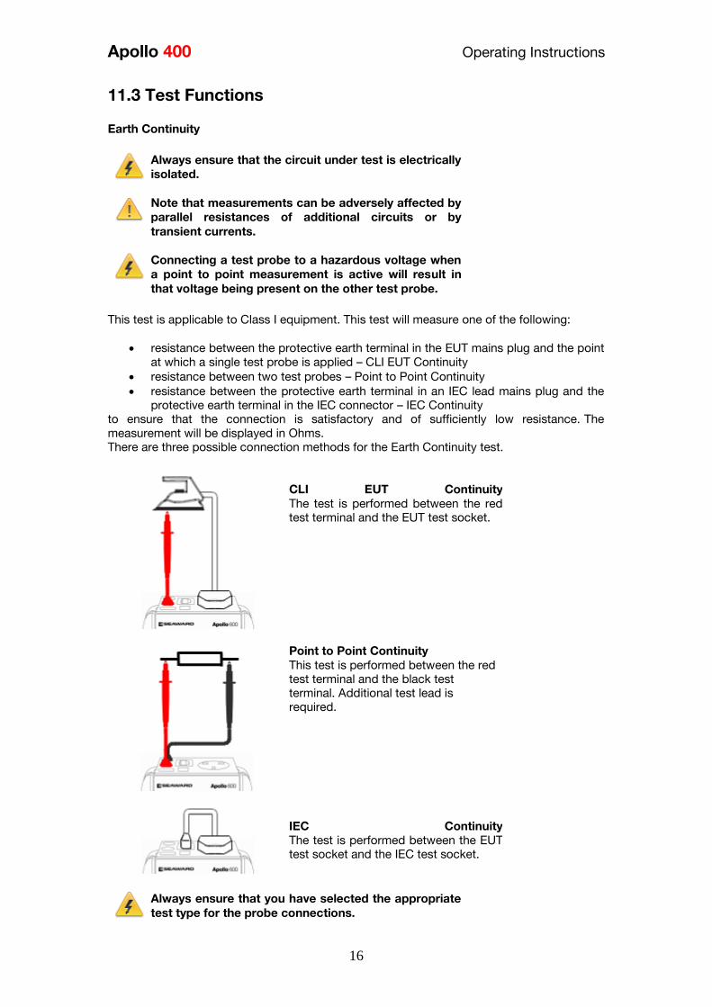
Apollo 400 Operating Instructions
16
113 Test Functions
Earth Continuity
Always ensure that the circuit under test is electrically
isolated
Note that measurements can be adversely affected by
parallel resistances of additional circuits or by
transient currents
Connecting a test probe to a hazardous voltage when
a point to point measurement is active will result in
that voltage being present on the other test probe This test is applicable to Class I equipment This test will measure one of the following
resistance between the protective earth terminal in the EUT mains plug and the point
at which a single test probe is applied ndash CLI EUT Continuity
resistance between two test probes ndash Point to Point Continuity resistance between the protective earth terminal in an IEC lead mains plug and the
protective earth terminal in the IEC connector ndash IEC Continuity to ensure that the connection is satisfactory and of sufficiently low resistance The
measurement will be displayed in Ohms There are three possible connection methods for the Earth Continuity test
CLI EUT Continuity
The test is performed between the red
test terminal and the EUT test socket
Point to Point Continuity
This test is performed between the red
test terminal and the black test
terminal Additional test lead is
required
IEC Continuity
The test is performed between the EUT
test socket and the IEC test socket
Always ensure that you have selected the appropriate
test type for the probe connections
Apollo 400 Operating Instructions
17
Selecting test type
In manual PAT test mode the earth continuity test can be switched between a Class I EUT
continuity test and a point to point continuity test as follows
Select Class I Continuity (1) and press the setup key (F3) In the Test Type field select EUT
Continuity Test or Point to Point Continuity Test
During automatic sequences the test type will be as per the test type programmed in the
test sequence Once the correct connections have been made for the selected test type press
the Start button The test will continue until it times out If we wish to abort the current test
press the Stop button Tests on IEC leads CLI EUTs can be performed using a current of
+200mA andor -200mA Tests performed in point to point mode are always performed
using a current +200mA test The direction of the test current can be reversed by switching
the test probes at the point of connection to the appliancecircuit under test
Nulling out the earth continuity test lead(s) resistance
For a more accurate earth continuity measurement the resistance of the test lead(s) can be
zeroed out The feature can be used with both the EUT Continuity and Point to Point
measurement modes
The null facility remains active even if the Apollo 400 is powered off until the feature is
deactivated by pressing the null key again or the Test Type is changed eg if a pair of test
leads are nulled for point to point measurement the null will be deactivated if the Test Type
is changed to EUT Continuity test
Nulling a single test lead
In the manual PAT screen press the setup key (F3) and change the Test Type to EUT
Continuity Test Press save (F4) Connect the earth continuity test lead to the earth continuity
test socket and connect the probe tip to the earth pin of the EUT socket Press Null (F4) to
measure and stored the test lead resistance When the null feature is active the Null icon will
appear on the display
Nulling both test leads
In the manual PAT screen press the setup key (F3) and change the Test Type to Point to
Point Continuity Test Press save (F4) Connect both earth continuity test leads to the earth
continuity test sockets and connect the probe tips together using the supplied alligator clips
Press Null (F4) to measure and stored the test lead resistance When the null feature is active
the Null icon will appear on the display
Insulation Resistance
Always ensure that the circuit under test is electrically
isolated
Connecting a test probe to a hazardous voltage when
a point to point measurement is active will result in
that voltage being present on the other test probe This test is applicable to Class I and Class II equipment This test will measure one of the
following
insulation resistance between live circuits and the protective earth circuit in the EUT
ndash Class I IEC lead insulation test insulation resistance between live circuits and a test probe applied to the EUT ndash
Class II insulation test
Apollo 400 Operating Instructions
18
insulation resistance between two test probes ndash Point to Point Insulation
to ensure that the test points are adequately insulated from one another The measurement
is displayed in MOhms There are three possible connection methods for the Insulation test
CLI and IEC Insulation
The test is performed between the EUT
test socket live and neutral and the EUT
test socket earth pin For IEC leads the other end of the lead
should be connected into the IEC test
socket
CLII Insulation
The test is performed between the EUT
test socket live and neutral and Red
test terminal
Point to Point Insulation
The test is performed between the Red
and Black test terminals both the
continuity test leads are required for
this test Additional test lead is
required
Always ensure that you have selected the correct test
connection method in the test for the probe
connections made
Ensure that the appliance mains switch is in the ON
position
During this test 250V or 500V DC is applied between
the two connections points The 500V DC potential
will be present across the two probe tips during a
Point to Point test
Selecting test type
In manual PAT test mode the insulation test can be switched between a 250V EUT
Insulation test 500V EUT Insulation test 250V Point to Point Insulation test or 500V Point to
Point Insulation test as follows
Apollo 400 Operating Instructions
19
Select Insulation Resistance (2) and press the setup key (F3) In the Test Type field select
the required test
During automatic sequences the test type will be as per the test type programmed in the
test sequence
In manual mode once the correct connections have been made for the selected test type
press the Start button in automatic mode the test will proceed automatically The test will
continue until it times out If we wish to abort the current test press the Stop button The
measurement will be displayed in Mega Ohms If an EUT fails the Insulation test then this may be because of internal filtering or an MOV
Retry the test at 250V or substitute the Insulation test with a Protective Conductor or Touch
Current test
Substitute Leakage
This test is applicable to Class I and Class II equipment This test is used to verify that the
leakage between the mains conductors of the EUT to the EUT earth pin or conductive
accessible surface of the enclosure is to a satisfactory low level There are two possible connection methods for the Substitute Leakage test
CLI and IEC Substitute Leakage
The test is performed between the EUT
test socket live and neutral and the EUT
socket earth pin
For IEC leads the other end of the lead
should be connected into the IEC test
socket
CLII Substitute Leakage The test is performed between the EUT
socket live and neutral and Red test
terminal
During this test 40V AC is applied between the earth pin and both the live and neutral
pins of the appliance mains supply plug In manual mode once the correct connections have been made for the selected test type
press the Start button in automatic mode the test will proceed automatically The test will
continue until it times out If we wish to abort the current test press the Stop button The
measurement will be displayed in milli Amps
This test can prove useful in situations where neither conventional insulation nor flash tests
are acceptable methods of testing the insulation of the appliance
Please note that values for substitute leakage may differ substantially from that of
Apollo 400 Operating Instructions
20
conventional earth leakage tests because of the way that the test is performed (eg it will be
affected by the presence of Neutral-to-Earth suppression capacitors)
Protective Earth (PE) Conductor Current
Always test the earth continuity and insulation
resistance before performing a PE Conductor Current
test
Always check that an appliance with moving parts (eg
an electric drill) is safely mounted to avoid risk of
damage to equipment or personnel
Avoid prolonged repeated use at full load (16A) and
excessive test duration as this may reduce the life of the
unit
Always ensure that appliance and leads which include
RCD protection that the RCD is reset at the beginning
of the test Failure to do so may result in incorrect
measurements being recorded
This test is applicable on Class I
Equipment The Apollo 400 should be connected to
a mains supply The EUT should be
connected into the EUT test socket In manual mode once the correct
connections have been made for the
selected test type press
the Start button in automatic mode the
test will proceed automatically
The test will continue until it times out If we wish to abort the current test press
the Stop button The measurement will be displayed in mA Should the test measurement over range then the test will be aborted immediately and a fail
will be logged
Touch Current
Warning Always test the insulation resistance before
performing a Touch Current test
Warning Always check that an appliance with moving
parts (eg an electric drill) is safely mounted to avoid
risk of damage to equipment or personnel
Attention Avoid prolonged repeated use at full load
(16A) and excessive test duration as this may reduce the
life of the unit
Always ensure that appliance and leads which include
RCD protection that the RCD is reset at the beginning
of the test Failure to do so may result in incorrect
measurements being recorded
Apollo 400 Operating Instructions
21
This test is applicable on Class I and
Class II Equipment The Apollo 400 should be connected to
a mains supply The EUT should be
connected into the EUT socket the red
test terminal should be connected to
point at which the leakage measurement
is required
In manual mode once the correct connections have been made for the selected test type
press the Start button in automatic mode the test will proceed automatically The test will
continue until it times out If we wish to abort the current test press the Stop button The
measurement will be displayed in milli Amps Should the test measurement over range then the test will be aborted immediately and a fail
will be logged
RCD Trip Time
Voltages between the protective conductor and earth
may influence measurements This test will pass a sinusoidal current of 30mA between the EUT socket and the IEC socket
and measure the time it takes for the in-line RCD to trip
Remove all other connections before performing an
RCD test
The Apollo 400 should be connected to
a mains supply The RCD should be
plugged into the EUT test socket and a
connection should be made from the
RCD mains output to the IEC test
socket
Once the correct connections have been made for the selected test type press
the Start button The RCD will be powered and you will be prompted to reset the RCD
When you have reset the RCD the Apollo 400 will count down and then perform the RCD
test the RCD trip time will be displayed The measurement will be displayed in milli seconds
IEC Lead Polarity
The IEC lead input is a test socket and is not intended
to be connected directly to mains Do not connect this
input to the mains supply
The Polarity test checks the wiring
polarity of an IEC lead the IEC should
be plugged into both the EUT and IEC
test sockets
This test can be used to test the wiring polarity of extension leads by plugging the supplied
test IEC lead into the end of the extension lead to complete the circuit to the IEC tests
socket In the automatic sequence editor the Polarity can be added to sequence In the manual
mode the polarity test is already part of a pre-defined test sequence which includes an Earth
Continuity test an Insulation test and the Polarity test
External Leakage Adaptors
Apollo 400 Operating Instructions
22
While using an External Leakage Adaptor the mains
supply will be connected to the EUT through the
adaptor
Ensure that when tests are performed using the
external Leakage Adaptor that the Earth Reverse
option is set to Off
The External Leakage Adaptor test
function is intended to used in
conjunction with the one of Seawards
external leakage adaptors Connect the
external leakage adaptor into the Red
test terminal connect the Earth
Continuity probe into the Black test
terminal
Connect the mains supply and the EUT
to the external leakage adaptor
Note that connecting both the EUT and mains supply to the external leakage adaptor will
connect the mains supply to the EUT
114 Checkbox Verification
A checkbox for the Apollo 400 is available as an optional accessory This can be used to
verify that the Apollo 400 test functions are working correctly When selecting the Checkbox
function follow the onscreen instructions
The Checkbox function will perform a number of
electrical tests Ensure that the onscreen instructions
are followed and that you do not touch the checkbox
during the active tests
12 Updating your Firmware
1 Go to wwwseawardcoukfirmware and save the latest Apollo 400 firmware file on
your PC
2 Power on the unit whilst holding down the F1 button
3 Press F2 to update via PC
4 Follow the onscreen instructions
5 Restart the unit
You can check the firmware version of your tester by
pressing this icon in the Home screen
Apollo 400 Operating Instructions
23
13 Electrical Specification
Earth Continuity
Output Current (Load 2Ω)
Test Voltage (oc)
Measuring Range
Display Range
Resolution Operating Error
Number of tests as per IEC61557-
4
+- 200mA DC with ZAP
gt 4VDC
005 Ωndash 1999 Ω
001 Ω ndash 1999 Ω
001 Ω +-5 + 4 counts
approx 1500
Insulation Test
Test Voltages
Test Current
Test Voltage Accuracy
Measuring Range
Display Range
Resolution Operating Error ( lt 10MΩ ) ( gt 10MΩ )
Number of tests as per IEC61557-
2
500V and 250V DC
1mA minimum for a load of
1kohmvolt lt2mA into sc
+20 -0
010M Ω to 1999M Ω
000M Ω to 1999M Ω
001M Ω +-5 +5 counts +-10 +5 counts approx 1500
Subsitute Leakage Test
Test Voltages
Measuring Range
Display Range
Resolution Operating Error
gt25Vac lt50Vac
020mA to 1999mA
000mA to 1999mA
001mA +-10 +2 digits
Protective Conductor Current
Test Voltage
Display Range
Measurement Range
Resolution
Operating Error
Frequency Response
Supply Voltage maximum
load current 16A
001mA to 1999mA
025mA to 1999mA
001mA
+-5 of reading +- 3 digits
40Hz to 25 kHz
Touch Current
Test Voltage
Display Range
Measurement Range
Resolution
Operating Error
Frequency Response
Supply Voltage maximum
load current 16A
000mA to 350mA
010mA to 350mA
001mA
+-5 of reading +- 2 digits
DC to 25 kHz
Apollo 400 Operating Instructions
24
Load PowerCurrent
Test Voltage
Display Range
Measurement Range
Resolution
Operating Error
Supply Voltage maximum
load current 16A
000 - 1600A
050 - 1600A
001A
+-10 of reading +- 5 digits
Lead Test
Test Voltage
Test 5V DC nominal
Live Neutral checks for oc
sc and crossed
Power Socket Test
Input voltage range
195V ndash 253V AC
Indicates configuration of
voltage potential-
Line potential phase to earth
Line potential phase to neutral
Line potential neutral to earth
RCD Test
Test Voltage
Test Current
Test Current Accuracy
Display Range
Measuring Range
Resolution
Operating Error
230V +10 -15
30mA 150mA rms sinusoidal
30mA -10 +0 150mA +10 -0
0 ndash 2000ms
1ms ndash 2000ms
1ms plusmn1ms
External Leakage
Test Voltage
Display Range
Measuring Range
Resolution
Operating Error
Connected to External
Adapter
0mA - 999mA
025mA - 999mA
001mA +-5 of reading +-2 digits
Apollo 400 Operating Instructions
25
14 Useful Information - 141 Factory Set Test Sequences
Test
Visual Earth Continuity Insulation PE Conductor
Current Touch Current
Substitute
Leakage Wiring
RCD
Trip
Time
Name
Duration
(s)
Limit
(ΩΩ) Duration (s) Voltage
Limit
(MΩΩ)
Duration
(s)
Limit
(mA)
Duration
(s)
Limit
(mA)
Duration
(s)
Limit
(mA)
Limit
(ms)
PortableHandheldIT CLI Yes 5 01 2 500 1
PortableHandheldIT CLII Yes 2 500 2
Fixed Appliance CLI Yes 2 01 5 500 1
Fixed Appliance CLII Yes 5 500 2
IEC Lead 2m Yes 5 02 2 500 1 Yes
13A 5m Surge Protected Lead Yes 5 02 2 250 1 Yes
13A 25m Ext Lead 30mA RCD Yes 5 05 5 08 30
Portable CLI PE Current Yes 5 05 2 250 1 5 08
Portable CLII Touch Current Yes 2 250 2 5 03
IT Equip CLI PE Current Yes 5 01 2 250 1 5 35
IT Equip CLII T ouch Current Yes 2 250 5 03
13A 6m Mains Lead Yes 5 02 2 500 1 Yes
13A 12m Mains Lead Yes 5 03 2 500 1 Yes
13A 24m Mains Lead Yes 5 05 2 500 1 Yes
MovStat CLI 500V Insulation Yes 5 01 2 500 1
MovStat CLII 500V Insulation Yes 2 500 2
MovStat CLI PE Current Yes 5 01 2 250 1 5 35
MovStat CLII Touch Current Yes 2 250 2 5 35
110V HandheldPortable CLI Yes 5 01 2 500 1 2 08
110V HandheldPortable CLII Yes 2 500 2 2 03
110V MovableStationary CLI Yes 5 01 2 500 1 2 35
110V MovableStationary CLII Yes 2 500 2 2 03
110V 25m Lead
RpeampInsulation Yes 5 05 2 500 1
Visual Only Yes
Apollo 400 Operating Instructions
26
142 Other Information
Parameter Default Min Max
Earth Continuity PF limit (Ω) 01 001 1999
Earth Continuity Duration (s) 5 2 30
Insulation Resistance PF limit (MΩ) 1 001 1999
Insulation Resistance Duration (s) 5 2 30
Substitute Leakage PF limit (mA) 075 025 15
Substitute Leakage Duration (s) 5 2 30
IEC Cord Earth Continuity PF limit
(ohms) 01 001 5
IEC Cord Insulation PF limit (MΩ) 1 001 1999
Touch Current PF limit (mA) 025 025 350
Touch Current Duration (s) 5 2 30
PE Conductor Current PF limit (mA) 075 025 1999
PE Conductor Current Duration (s) 5 2 30
External Adapter Continuity (Ω) 01 001 5
External Adapter Leakage (mA) 075 025 999
External Adapter Duration (s) 5 2 30
RCD 30mA trip time (ms) 200 1 2000
RCD 150mA trip time (ms) 40 1 40
Number of tests in a test sequence 1 60
Characters in a test sequence name 1 30
Characters in a User Test name 1 15
Characters in a User Test Unit 15
Total number of Test Sequences 25
Test Results (typical) 2000
Sites 50
Characters in Site name 1 15
Locations 50
Characters in Location name 1 15
Users (including admin) 2
Characters in User name 1 15
Comments List 50
Characters in Comment 25
Characters in Asset ID 1 15
Apollo 400 Operating Instructions
27
15 Environmental Conditions
The Apollo 400 has been designed to perform tests and measurements in a dry environment
Maximum barometric elevation for making measurements is 2000M
Pollution degree 2 according to IEC 60529
Electromagnetic compatibility (EMC) Interference immunity and emitted interference
conforming to IEC 61326-1
Operating temperature range of 0 to 40 degrees C without moisture condensation
Operating Altitude 0 to 2000 metres
16 Maintenance
161 Charging the battery pack
The battery pack will be charged whenever the Apollo 400 is connected to the mains supply
regardless of whether it is switched on or off
The typical charging current is set to 500mA but this may vary as the instrument also
includes pre-charge and top up charge modes
When no tests are being performed the battery pack will be fully re-charged after 7 hours
162 Securing the Apollo 400
Under certain conditions safe operation of the Apollo 400 can no longer be assumed
Visible damage of the instrument case
Incorrect measurement results
Recognisable abuse to the instrument due to prolonged storage under improper conditions
Recognisable abuse to the instrument due to extraordinary transportation stress
In these case the Apollo 400 should be immediately switched off disconnected from any test
and measurement function and secured to prevent any further use
163 Cleaning the Apollo 400
Clean the external case of the Apollo 400 with a dry clean cloth
Avoid using solvents and abrasive scouring agents to clean the external case of the Apollo
400
Apollo 400 Operating Instructions
28
164 Replacing the battery pack
Before opening the Apollo 400 battery compartment
ensure that all test leads and accessories are
disconnected
Power off the instrument
Disconnect all test leads and accessories
Position the instrument face down and remove the screw holding the battery compartment
cover in place
Remove the battery compartment cover
Remove the battery pack from the compartment and unplug the 4 way connector
Connect the 4 way connector of the new battery to the 4 way header in the battery
compartment put the battery pack into the compartment
Relocate the battery compartment cover and fasten in position with the battery compartment
screw
ONLY USE A REPLACEMENT BATTERY PACK THAT HAS BEEN SUPPLIED BY SEAWARD
OR A SEAWARD APPROVED DISTRIBUTOR
17 Support
The Apollo 400 must be registered with Seaward before support will be made available For Technical Support contact Tel (+44) 191 587 8718
For help or advice on Service and Calibration contact
CalibrationHouse Seaward Electronic Bracken Hill South West Industrial Estate Peterlee Co Durham SR8 2SW England Tel (+44) 191 5878739 (+44) 191 5878737 Email serviceseawardcouk
Calibration House is part of the Seaward Group
Apollo 400 Operating Instructions
29
171 Register your product here-
wwwseawardcouk 172 Calibration Services-
wwwcalibrationhousecouk Bracken Hill South West Industrial Estate Peterlee County Durham SR8 2SW Co Durham SR8 2SW England Tel (+44) 191 5863511 Some icons provided by Fat Cow (httpwwwfatcowcomfree-icons) Based in part on the work of the Qwt project (httpqwtsfnet)
Apollo 400A simple no-nonsense PAT tester with fast data entry and storage for up to 2000appliance records
Key Featuresn High definition colour displayn Store 2000 appliance recordsn Remote data transfer from field to office n Bluetooth connectivity
Electrical Test Functionsn Low current earth continuity test guaranteeing accurate measurement n Point to point testing (earth continuity and insulation resistance)n Insulation resistancen IEC lead testn Protective conductor currentn Touch currentn Load powercurrentn Alternative leakage currentn RCD testn Power socket test
Ideal Forn Electrical Contractorsn Facilities Managersn Operations Managers
Apollo 400 offers simple electrical safety testing with straightforward data entryusing the intuitive QWERTY keypad
A comprehensive range of electrical safety tests ensure compliance with theIET 4th Edition Code of Practice whilst remote data transfer and USB downloadmakes data management easy and efficient
The Apollo 400 is ideal for mid-volume PAT testing where detailed records arerequired
Streamline the PAT testing process further by using the Apollo 400 with acompatible label printer barcode scanner and PATGuard 3 software
wwwseawardcoukapollo400
Tel +44 (0) 191 587 8741Email salesseawardcouk
Requires optional accessory (part number 380A983)
Straightforward PAT testing with simple data managementApollo 400 offers a comprehensive suite of electrical safetytests to enable any workplace appliance to be tested including3-phase equipment fixed appliances and RCDs
The QWERTY keypad enables asset information to be entered quicklyand easily while a large colour display with an intuitive menu structure makesthe Apollo 400 simple to grasp Lightweight and small in size with battery or mainspower modes the Apollo 400 is good to go in seconds allowing more appliances to betested without downtime for boot-up or a battery re-charge
Superb software for total traceabilityApollo 400 has an internal memory capable of storing up to 2000electrical test records Its compatibility with Seawardrsquos PATGuard 3software means that complete test records are easily managed ona PC
Transfer data to the PC remotely using the Bluetooth function anda smartphone or download the results via a USB cable directly toa PC Once downloaded to PATGuard 3 it is easy to keep track ofthe history of test and inspections as well as produce reportscertificates and invoices ndash offering total peace of mind and quickereasier management of scheduling inspections and tests
Download a free trial at wwwseawardcoukpg3trial
wwwseawardcoukapollo400
Tel +44 (0) 191 587 8741Email salesseawardcouk
additional accessory required for point to point testing
u Accessory BundlesThe Apollo 400 is available to buy with a selectionof optional accessory bundles to help you get themost out of your tester
Apollo 400 is supplied as standard with a UKAScalibration certificate and a 2 yearmanufacturerrsquos warranty (subject to terms andconditions)
Greater efficiency through useful accessoriesAs with many Seaward PAT testers the Apollo 400 is compatible with arange of printers and barcode scanners further speeding up the processof asset recognition testing and labelling
Also available in this range
A multi-tasking and fully customisable PAT with additionalhealth and safety features and on-board camera forunrivalled record keeping
Apollo 600 includes a universal risk assessment tool andthe ability to store up to 50000 appliance records plus2000 images - providing visual evidence of testenvironments perfect for advanced record-keeping inorganisations with high-volume workplace test andinspection routines
Apollo 600Multi-tasking PAT tester with on-board camera
wwwseawardcoukapollo400
Tel +44 (0) 191 587 8741Email salesseawardcouk
A powerful PAT tester with a built-in PAT retest calculatorand flexible user-configurable sequences for recordingany non-electrical workplace test or inspection
The ability to customise a number of settings and a largememory to store up to 10000 appliance records makesthe Apollo 500 a versatile and dependable tool for highvolume PAT testing
Apollo 500A fast amp fully customisable and versatile PAT tester
Optional accessory bundles available Part Number
Elite Bundle n Test n Tag Elite 2 rugged portable printer
n Test n Tag printer labels x 4
n Bluetooth barcode scanner
n Apollo kit carry case
n 110V adapter
Includes Apollo 400 tester
380A978
Elite Bundle +Software
PLUS PATGuard 3 software 1yr licence 380A979
Pro Bundle n Test n Tag Pro lightweight portable printer
n Test n Tag printer labels x 4
n Bluetooth barcode scanner
n Apollo kit carry case
n 110V adapter
Includes Apollo 400 tester
380A980
Pro Bundle +Software PLUS PATGuard 3 software 1yr licence 380A981
wwwseawardcoukapollo400
Tel +44 (0) 191 587 8741Email salesseawardcouk
Apollo 400 Apollo 500 Apollo 600
General Features
Battery amp mains powered n n n
Colour Screen amp QWERTY keypad n n n
Large internal memory 2000 records 10000 records 50000 records
Scanner amp printer compatible n n n
Password controlled user accounts n n
Set up multiple user accounts with varyinglevels of privileges
n n
Clone facility to set up multiple testers n n
Checkbox supplied as standard n n
On-board user manual n n
Test amp InspectionFeatures
Auto-increment asset ID n n
PAT Setup option to allow for custom menus n n
Enter asset description after test usingkeypad or barcode scanner
n n n
Comprehensive electrical safety test features n n n
Point to point measurement (Rpe amp IR)
n
(optional
accessory
required)
n n
User configurable electrical testvisualinspection sequences 25 100 100
User set sites amp locations 50 100 100
Risk based retest period calculator n n
User definable comments lines against testrecords
n n
Configurable checklists for any workplacetest or inspection (user tests)
n n
On-board camera n
Universal risk assessment n
Health amp safety certificates n
Data Transfer
Bluetooth connectivity n n n
Barcode scanner connectivity n n n
Print Pass amp Fail labels n n n
Add your company logo to labels n n
Select from various label formats to print n n
Remote data transfer via mobile device n
(Android only)
n
(Android only)
n
(Android and iOS)
Download to PC via USB cable n n n
Filter results to be downloaded n n
Upload previous results to tester for retest n n
Data transfer via USB flash drive n
Apollo Series Comparison Chart
PAT TESTS
Earth ContinuityTest Current +- 200mA DC Display Range 001 ndash 1999ΩPass Value User Defined
Insulation ResistanceTest Voltage 500V 250VDC 1mA nominalDisplay Range 001MΩ - 1999MΩPass Value User Defined
IEC Lead TestTest Voltage 5VAC nominalTest Live Neutral Checks for oc sc and crossed
Protective Conductor CurrentLoad
Test Voltage Supply voltage maximum load current 16A Display Ranges 001mA to 1999mA Pass Value User Defined
Touch Current
Test Voltage Supply Voltage maximum load current 16ADisplay Range 000 ndash 350mA Pass Value User defined
Load PowerCurrent
Test Voltage Supply Voltage maximum load current 16ATest Duration Programmable up to a maximum of 255s depending on load ie max duration is reduced for high loadsDisplay Range 000kVA ndash 400kVA 000A ndash 1600A
Alternative Leakage Current
Test Voltages gt25VAC lt50VAC Display Range 000mA to 1999mAPass Value User Defined
RCD Test
Test Voltage 230V +10 -15Test Current 30mA 150mA rms sinusoidalDisplay Range 0ms - 2000ms (30mA) 0-40ms (150mA)Test Method Internal isolation to avoid tripping distribution board RCD
Power Socket Test
Voltage Range 207V ndash 253VACIndicates configuration of voltage potential-Line potential phase to earthLine potential phase to neutralLine potential neutral to earth
General
Memory Size 2000 recordsWeight 15kgDimensions 230mm x 150mm x 100mmPower Source Mains or rechargeable battery pack
Standard Accessories (supplied with Apollo 400)30 day free trial of PATGuard 3 software 1x red test lead and probe with crocodile clip05m IEC leadMains power leadUSB download cableQuick start guideUKAS calibration certificate
Optional Accessories Test n Tag Elite 2 Bluetooth printer with roll of small labels (339A995)Test n Tag Pro Bluetooth printer with roll of small labels (339A987)Roll of small labels (approx 350 off 52 x 25mm labels) (339A947)Additional black test lead and probe with crocodile clip (for point to point testing) (380A983)Bluetooth barcode scanner (339A923)110V test adaptor (270A076)110V to IEC adapter (344A050)Apollo checkbox (380A953)3 Phase Leakage Adaptor 5 Star 16A (391A920)3 Phase Leakage Adaptor 5 Star 32A (391A910)3 Phase Adapter Delta 4 pin 16A 415V (for Rpe amp IR) (209A910)3 Phase Adapter Star 5 pin 16A 415V (for Rpe amp IR) (209A911)3 Phase Adapter Delta 4 pin 32A 415V (for Rpe amp IR) (209A912)3 Phase Adapter Star 5 pin 32A 415V (for Rpe amp IR) (209A913)Professional Seaward kit bag (71G109)Apollo carry case (380A952)PATGuard 3 software ndash download 30 day free trial atwwwseawardcoukpg3trial
Part NumbersApollo 400 standard package 380A920Apollo 400 with Elite accessory bundle 380A978Apollo 400 with Elite accessory bundle amp PATGuard 3 one year licence380A979Apollo 400 with Pro accessory bundle 380A980Apollo 400 with Pro accessory bundle amp PATGuard 3 one year licence380A981
TrainingSeaward offer a range of PAT testing courses including City amp GuildsGo to wwwseawardcouktraining for more information
Services2 year warranty (subject to terms and conditions available atwwwseawardcoukwarranty24)Service amp Calibration by CalibrationhouseGo to wwwcalibrationhousecom for more information
Technical Specifications
Part of
Rev 12
wwwseawardcoukapollo400
Tel +44 (0) 191 587 8741Email salesseawardcouk
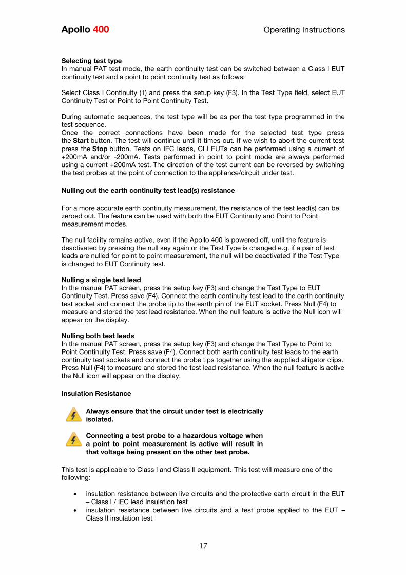
Apollo 400 Operating Instructions
17
Selecting test type
In manual PAT test mode the earth continuity test can be switched between a Class I EUT
continuity test and a point to point continuity test as follows
Select Class I Continuity (1) and press the setup key (F3) In the Test Type field select EUT
Continuity Test or Point to Point Continuity Test
During automatic sequences the test type will be as per the test type programmed in the
test sequence Once the correct connections have been made for the selected test type press
the Start button The test will continue until it times out If we wish to abort the current test
press the Stop button Tests on IEC leads CLI EUTs can be performed using a current of
+200mA andor -200mA Tests performed in point to point mode are always performed
using a current +200mA test The direction of the test current can be reversed by switching
the test probes at the point of connection to the appliancecircuit under test
Nulling out the earth continuity test lead(s) resistance
For a more accurate earth continuity measurement the resistance of the test lead(s) can be
zeroed out The feature can be used with both the EUT Continuity and Point to Point
measurement modes
The null facility remains active even if the Apollo 400 is powered off until the feature is
deactivated by pressing the null key again or the Test Type is changed eg if a pair of test
leads are nulled for point to point measurement the null will be deactivated if the Test Type
is changed to EUT Continuity test
Nulling a single test lead
In the manual PAT screen press the setup key (F3) and change the Test Type to EUT
Continuity Test Press save (F4) Connect the earth continuity test lead to the earth continuity
test socket and connect the probe tip to the earth pin of the EUT socket Press Null (F4) to
measure and stored the test lead resistance When the null feature is active the Null icon will
appear on the display
Nulling both test leads
In the manual PAT screen press the setup key (F3) and change the Test Type to Point to
Point Continuity Test Press save (F4) Connect both earth continuity test leads to the earth
continuity test sockets and connect the probe tips together using the supplied alligator clips
Press Null (F4) to measure and stored the test lead resistance When the null feature is active
the Null icon will appear on the display
Insulation Resistance
Always ensure that the circuit under test is electrically
isolated
Connecting a test probe to a hazardous voltage when
a point to point measurement is active will result in
that voltage being present on the other test probe This test is applicable to Class I and Class II equipment This test will measure one of the
following
insulation resistance between live circuits and the protective earth circuit in the EUT
ndash Class I IEC lead insulation test insulation resistance between live circuits and a test probe applied to the EUT ndash
Class II insulation test
Apollo 400 Operating Instructions
18
insulation resistance between two test probes ndash Point to Point Insulation
to ensure that the test points are adequately insulated from one another The measurement
is displayed in MOhms There are three possible connection methods for the Insulation test
CLI and IEC Insulation
The test is performed between the EUT
test socket live and neutral and the EUT
test socket earth pin For IEC leads the other end of the lead
should be connected into the IEC test
socket
CLII Insulation
The test is performed between the EUT
test socket live and neutral and Red
test terminal
Point to Point Insulation
The test is performed between the Red
and Black test terminals both the
continuity test leads are required for
this test Additional test lead is
required
Always ensure that you have selected the correct test
connection method in the test for the probe
connections made
Ensure that the appliance mains switch is in the ON
position
During this test 250V or 500V DC is applied between
the two connections points The 500V DC potential
will be present across the two probe tips during a
Point to Point test
Selecting test type
In manual PAT test mode the insulation test can be switched between a 250V EUT
Insulation test 500V EUT Insulation test 250V Point to Point Insulation test or 500V Point to
Point Insulation test as follows
Apollo 400 Operating Instructions
19
Select Insulation Resistance (2) and press the setup key (F3) In the Test Type field select
the required test
During automatic sequences the test type will be as per the test type programmed in the
test sequence
In manual mode once the correct connections have been made for the selected test type
press the Start button in automatic mode the test will proceed automatically The test will
continue until it times out If we wish to abort the current test press the Stop button The
measurement will be displayed in Mega Ohms If an EUT fails the Insulation test then this may be because of internal filtering or an MOV
Retry the test at 250V or substitute the Insulation test with a Protective Conductor or Touch
Current test
Substitute Leakage
This test is applicable to Class I and Class II equipment This test is used to verify that the
leakage between the mains conductors of the EUT to the EUT earth pin or conductive
accessible surface of the enclosure is to a satisfactory low level There are two possible connection methods for the Substitute Leakage test
CLI and IEC Substitute Leakage
The test is performed between the EUT
test socket live and neutral and the EUT
socket earth pin
For IEC leads the other end of the lead
should be connected into the IEC test
socket
CLII Substitute Leakage The test is performed between the EUT
socket live and neutral and Red test
terminal
During this test 40V AC is applied between the earth pin and both the live and neutral
pins of the appliance mains supply plug In manual mode once the correct connections have been made for the selected test type
press the Start button in automatic mode the test will proceed automatically The test will
continue until it times out If we wish to abort the current test press the Stop button The
measurement will be displayed in milli Amps
This test can prove useful in situations where neither conventional insulation nor flash tests
are acceptable methods of testing the insulation of the appliance
Please note that values for substitute leakage may differ substantially from that of
Apollo 400 Operating Instructions
20
conventional earth leakage tests because of the way that the test is performed (eg it will be
affected by the presence of Neutral-to-Earth suppression capacitors)
Protective Earth (PE) Conductor Current
Always test the earth continuity and insulation
resistance before performing a PE Conductor Current
test
Always check that an appliance with moving parts (eg
an electric drill) is safely mounted to avoid risk of
damage to equipment or personnel
Avoid prolonged repeated use at full load (16A) and
excessive test duration as this may reduce the life of the
unit
Always ensure that appliance and leads which include
RCD protection that the RCD is reset at the beginning
of the test Failure to do so may result in incorrect
measurements being recorded
This test is applicable on Class I
Equipment The Apollo 400 should be connected to
a mains supply The EUT should be
connected into the EUT test socket In manual mode once the correct
connections have been made for the
selected test type press
the Start button in automatic mode the
test will proceed automatically
The test will continue until it times out If we wish to abort the current test press
the Stop button The measurement will be displayed in mA Should the test measurement over range then the test will be aborted immediately and a fail
will be logged
Touch Current
Warning Always test the insulation resistance before
performing a Touch Current test
Warning Always check that an appliance with moving
parts (eg an electric drill) is safely mounted to avoid
risk of damage to equipment or personnel
Attention Avoid prolonged repeated use at full load
(16A) and excessive test duration as this may reduce the
life of the unit
Always ensure that appliance and leads which include
RCD protection that the RCD is reset at the beginning
of the test Failure to do so may result in incorrect
measurements being recorded
Apollo 400 Operating Instructions
21
This test is applicable on Class I and
Class II Equipment The Apollo 400 should be connected to
a mains supply The EUT should be
connected into the EUT socket the red
test terminal should be connected to
point at which the leakage measurement
is required
In manual mode once the correct connections have been made for the selected test type
press the Start button in automatic mode the test will proceed automatically The test will
continue until it times out If we wish to abort the current test press the Stop button The
measurement will be displayed in milli Amps Should the test measurement over range then the test will be aborted immediately and a fail
will be logged
RCD Trip Time
Voltages between the protective conductor and earth
may influence measurements This test will pass a sinusoidal current of 30mA between the EUT socket and the IEC socket
and measure the time it takes for the in-line RCD to trip
Remove all other connections before performing an
RCD test
The Apollo 400 should be connected to
a mains supply The RCD should be
plugged into the EUT test socket and a
connection should be made from the
RCD mains output to the IEC test
socket
Once the correct connections have been made for the selected test type press
the Start button The RCD will be powered and you will be prompted to reset the RCD
When you have reset the RCD the Apollo 400 will count down and then perform the RCD
test the RCD trip time will be displayed The measurement will be displayed in milli seconds
IEC Lead Polarity
The IEC lead input is a test socket and is not intended
to be connected directly to mains Do not connect this
input to the mains supply
The Polarity test checks the wiring
polarity of an IEC lead the IEC should
be plugged into both the EUT and IEC
test sockets
This test can be used to test the wiring polarity of extension leads by plugging the supplied
test IEC lead into the end of the extension lead to complete the circuit to the IEC tests
socket In the automatic sequence editor the Polarity can be added to sequence In the manual
mode the polarity test is already part of a pre-defined test sequence which includes an Earth
Continuity test an Insulation test and the Polarity test
External Leakage Adaptors
Apollo 400 Operating Instructions
22
While using an External Leakage Adaptor the mains
supply will be connected to the EUT through the
adaptor
Ensure that when tests are performed using the
external Leakage Adaptor that the Earth Reverse
option is set to Off
The External Leakage Adaptor test
function is intended to used in
conjunction with the one of Seawards
external leakage adaptors Connect the
external leakage adaptor into the Red
test terminal connect the Earth
Continuity probe into the Black test
terminal
Connect the mains supply and the EUT
to the external leakage adaptor
Note that connecting both the EUT and mains supply to the external leakage adaptor will
connect the mains supply to the EUT
114 Checkbox Verification
A checkbox for the Apollo 400 is available as an optional accessory This can be used to
verify that the Apollo 400 test functions are working correctly When selecting the Checkbox
function follow the onscreen instructions
The Checkbox function will perform a number of
electrical tests Ensure that the onscreen instructions
are followed and that you do not touch the checkbox
during the active tests
12 Updating your Firmware
1 Go to wwwseawardcoukfirmware and save the latest Apollo 400 firmware file on
your PC
2 Power on the unit whilst holding down the F1 button
3 Press F2 to update via PC
4 Follow the onscreen instructions
5 Restart the unit
You can check the firmware version of your tester by
pressing this icon in the Home screen
Apollo 400 Operating Instructions
23
13 Electrical Specification
Earth Continuity
Output Current (Load 2Ω)
Test Voltage (oc)
Measuring Range
Display Range
Resolution Operating Error
Number of tests as per IEC61557-
4
+- 200mA DC with ZAP
gt 4VDC
005 Ωndash 1999 Ω
001 Ω ndash 1999 Ω
001 Ω +-5 + 4 counts
approx 1500
Insulation Test
Test Voltages
Test Current
Test Voltage Accuracy
Measuring Range
Display Range
Resolution Operating Error ( lt 10MΩ ) ( gt 10MΩ )
Number of tests as per IEC61557-
2
500V and 250V DC
1mA minimum for a load of
1kohmvolt lt2mA into sc
+20 -0
010M Ω to 1999M Ω
000M Ω to 1999M Ω
001M Ω +-5 +5 counts +-10 +5 counts approx 1500
Subsitute Leakage Test
Test Voltages
Measuring Range
Display Range
Resolution Operating Error
gt25Vac lt50Vac
020mA to 1999mA
000mA to 1999mA
001mA +-10 +2 digits
Protective Conductor Current
Test Voltage
Display Range
Measurement Range
Resolution
Operating Error
Frequency Response
Supply Voltage maximum
load current 16A
001mA to 1999mA
025mA to 1999mA
001mA
+-5 of reading +- 3 digits
40Hz to 25 kHz
Touch Current
Test Voltage
Display Range
Measurement Range
Resolution
Operating Error
Frequency Response
Supply Voltage maximum
load current 16A
000mA to 350mA
010mA to 350mA
001mA
+-5 of reading +- 2 digits
DC to 25 kHz
Apollo 400 Operating Instructions
24
Load PowerCurrent
Test Voltage
Display Range
Measurement Range
Resolution
Operating Error
Supply Voltage maximum
load current 16A
000 - 1600A
050 - 1600A
001A
+-10 of reading +- 5 digits
Lead Test
Test Voltage
Test 5V DC nominal
Live Neutral checks for oc
sc and crossed
Power Socket Test
Input voltage range
195V ndash 253V AC
Indicates configuration of
voltage potential-
Line potential phase to earth
Line potential phase to neutral
Line potential neutral to earth
RCD Test
Test Voltage
Test Current
Test Current Accuracy
Display Range
Measuring Range
Resolution
Operating Error
230V +10 -15
30mA 150mA rms sinusoidal
30mA -10 +0 150mA +10 -0
0 ndash 2000ms
1ms ndash 2000ms
1ms plusmn1ms
External Leakage
Test Voltage
Display Range
Measuring Range
Resolution
Operating Error
Connected to External
Adapter
0mA - 999mA
025mA - 999mA
001mA +-5 of reading +-2 digits
Apollo 400 Operating Instructions
25
14 Useful Information - 141 Factory Set Test Sequences
Test
Visual Earth Continuity Insulation PE Conductor
Current Touch Current
Substitute
Leakage Wiring
RCD
Trip
Time
Name
Duration
(s)
Limit
(ΩΩ) Duration (s) Voltage
Limit
(MΩΩ)
Duration
(s)
Limit
(mA)
Duration
(s)
Limit
(mA)
Duration
(s)
Limit
(mA)
Limit
(ms)
PortableHandheldIT CLI Yes 5 01 2 500 1
PortableHandheldIT CLII Yes 2 500 2
Fixed Appliance CLI Yes 2 01 5 500 1
Fixed Appliance CLII Yes 5 500 2
IEC Lead 2m Yes 5 02 2 500 1 Yes
13A 5m Surge Protected Lead Yes 5 02 2 250 1 Yes
13A 25m Ext Lead 30mA RCD Yes 5 05 5 08 30
Portable CLI PE Current Yes 5 05 2 250 1 5 08
Portable CLII Touch Current Yes 2 250 2 5 03
IT Equip CLI PE Current Yes 5 01 2 250 1 5 35
IT Equip CLII T ouch Current Yes 2 250 5 03
13A 6m Mains Lead Yes 5 02 2 500 1 Yes
13A 12m Mains Lead Yes 5 03 2 500 1 Yes
13A 24m Mains Lead Yes 5 05 2 500 1 Yes
MovStat CLI 500V Insulation Yes 5 01 2 500 1
MovStat CLII 500V Insulation Yes 2 500 2
MovStat CLI PE Current Yes 5 01 2 250 1 5 35
MovStat CLII Touch Current Yes 2 250 2 5 35
110V HandheldPortable CLI Yes 5 01 2 500 1 2 08
110V HandheldPortable CLII Yes 2 500 2 2 03
110V MovableStationary CLI Yes 5 01 2 500 1 2 35
110V MovableStationary CLII Yes 2 500 2 2 03
110V 25m Lead
RpeampInsulation Yes 5 05 2 500 1
Visual Only Yes
Apollo 400 Operating Instructions
26
142 Other Information
Parameter Default Min Max
Earth Continuity PF limit (Ω) 01 001 1999
Earth Continuity Duration (s) 5 2 30
Insulation Resistance PF limit (MΩ) 1 001 1999
Insulation Resistance Duration (s) 5 2 30
Substitute Leakage PF limit (mA) 075 025 15
Substitute Leakage Duration (s) 5 2 30
IEC Cord Earth Continuity PF limit
(ohms) 01 001 5
IEC Cord Insulation PF limit (MΩ) 1 001 1999
Touch Current PF limit (mA) 025 025 350
Touch Current Duration (s) 5 2 30
PE Conductor Current PF limit (mA) 075 025 1999
PE Conductor Current Duration (s) 5 2 30
External Adapter Continuity (Ω) 01 001 5
External Adapter Leakage (mA) 075 025 999
External Adapter Duration (s) 5 2 30
RCD 30mA trip time (ms) 200 1 2000
RCD 150mA trip time (ms) 40 1 40
Number of tests in a test sequence 1 60
Characters in a test sequence name 1 30
Characters in a User Test name 1 15
Characters in a User Test Unit 15
Total number of Test Sequences 25
Test Results (typical) 2000
Sites 50
Characters in Site name 1 15
Locations 50
Characters in Location name 1 15
Users (including admin) 2
Characters in User name 1 15
Comments List 50
Characters in Comment 25
Characters in Asset ID 1 15
Apollo 400 Operating Instructions
27
15 Environmental Conditions
The Apollo 400 has been designed to perform tests and measurements in a dry environment
Maximum barometric elevation for making measurements is 2000M
Pollution degree 2 according to IEC 60529
Electromagnetic compatibility (EMC) Interference immunity and emitted interference
conforming to IEC 61326-1
Operating temperature range of 0 to 40 degrees C without moisture condensation
Operating Altitude 0 to 2000 metres
16 Maintenance
161 Charging the battery pack
The battery pack will be charged whenever the Apollo 400 is connected to the mains supply
regardless of whether it is switched on or off
The typical charging current is set to 500mA but this may vary as the instrument also
includes pre-charge and top up charge modes
When no tests are being performed the battery pack will be fully re-charged after 7 hours
162 Securing the Apollo 400
Under certain conditions safe operation of the Apollo 400 can no longer be assumed
Visible damage of the instrument case
Incorrect measurement results
Recognisable abuse to the instrument due to prolonged storage under improper conditions
Recognisable abuse to the instrument due to extraordinary transportation stress
In these case the Apollo 400 should be immediately switched off disconnected from any test
and measurement function and secured to prevent any further use
163 Cleaning the Apollo 400
Clean the external case of the Apollo 400 with a dry clean cloth
Avoid using solvents and abrasive scouring agents to clean the external case of the Apollo
400
Apollo 400 Operating Instructions
28
164 Replacing the battery pack
Before opening the Apollo 400 battery compartment
ensure that all test leads and accessories are
disconnected
Power off the instrument
Disconnect all test leads and accessories
Position the instrument face down and remove the screw holding the battery compartment
cover in place
Remove the battery compartment cover
Remove the battery pack from the compartment and unplug the 4 way connector
Connect the 4 way connector of the new battery to the 4 way header in the battery
compartment put the battery pack into the compartment
Relocate the battery compartment cover and fasten in position with the battery compartment
screw
ONLY USE A REPLACEMENT BATTERY PACK THAT HAS BEEN SUPPLIED BY SEAWARD
OR A SEAWARD APPROVED DISTRIBUTOR
17 Support
The Apollo 400 must be registered with Seaward before support will be made available For Technical Support contact Tel (+44) 191 587 8718
For help or advice on Service and Calibration contact
CalibrationHouse Seaward Electronic Bracken Hill South West Industrial Estate Peterlee Co Durham SR8 2SW England Tel (+44) 191 5878739 (+44) 191 5878737 Email serviceseawardcouk
Calibration House is part of the Seaward Group
Apollo 400 Operating Instructions
29
171 Register your product here-
wwwseawardcouk 172 Calibration Services-
wwwcalibrationhousecouk Bracken Hill South West Industrial Estate Peterlee County Durham SR8 2SW Co Durham SR8 2SW England Tel (+44) 191 5863511 Some icons provided by Fat Cow (httpwwwfatcowcomfree-icons) Based in part on the work of the Qwt project (httpqwtsfnet)
Apollo 400A simple no-nonsense PAT tester with fast data entry and storage for up to 2000appliance records
Key Featuresn High definition colour displayn Store 2000 appliance recordsn Remote data transfer from field to office n Bluetooth connectivity
Electrical Test Functionsn Low current earth continuity test guaranteeing accurate measurement n Point to point testing (earth continuity and insulation resistance)n Insulation resistancen IEC lead testn Protective conductor currentn Touch currentn Load powercurrentn Alternative leakage currentn RCD testn Power socket test
Ideal Forn Electrical Contractorsn Facilities Managersn Operations Managers
Apollo 400 offers simple electrical safety testing with straightforward data entryusing the intuitive QWERTY keypad
A comprehensive range of electrical safety tests ensure compliance with theIET 4th Edition Code of Practice whilst remote data transfer and USB downloadmakes data management easy and efficient
The Apollo 400 is ideal for mid-volume PAT testing where detailed records arerequired
Streamline the PAT testing process further by using the Apollo 400 with acompatible label printer barcode scanner and PATGuard 3 software
wwwseawardcoukapollo400
Tel +44 (0) 191 587 8741Email salesseawardcouk
Requires optional accessory (part number 380A983)
Straightforward PAT testing with simple data managementApollo 400 offers a comprehensive suite of electrical safetytests to enable any workplace appliance to be tested including3-phase equipment fixed appliances and RCDs
The QWERTY keypad enables asset information to be entered quicklyand easily while a large colour display with an intuitive menu structure makesthe Apollo 400 simple to grasp Lightweight and small in size with battery or mainspower modes the Apollo 400 is good to go in seconds allowing more appliances to betested without downtime for boot-up or a battery re-charge
Superb software for total traceabilityApollo 400 has an internal memory capable of storing up to 2000electrical test records Its compatibility with Seawardrsquos PATGuard 3software means that complete test records are easily managed ona PC
Transfer data to the PC remotely using the Bluetooth function anda smartphone or download the results via a USB cable directly toa PC Once downloaded to PATGuard 3 it is easy to keep track ofthe history of test and inspections as well as produce reportscertificates and invoices ndash offering total peace of mind and quickereasier management of scheduling inspections and tests
Download a free trial at wwwseawardcoukpg3trial
wwwseawardcoukapollo400
Tel +44 (0) 191 587 8741Email salesseawardcouk
additional accessory required for point to point testing
u Accessory BundlesThe Apollo 400 is available to buy with a selectionof optional accessory bundles to help you get themost out of your tester
Apollo 400 is supplied as standard with a UKAScalibration certificate and a 2 yearmanufacturerrsquos warranty (subject to terms andconditions)
Greater efficiency through useful accessoriesAs with many Seaward PAT testers the Apollo 400 is compatible with arange of printers and barcode scanners further speeding up the processof asset recognition testing and labelling
Also available in this range
A multi-tasking and fully customisable PAT with additionalhealth and safety features and on-board camera forunrivalled record keeping
Apollo 600 includes a universal risk assessment tool andthe ability to store up to 50000 appliance records plus2000 images - providing visual evidence of testenvironments perfect for advanced record-keeping inorganisations with high-volume workplace test andinspection routines
Apollo 600Multi-tasking PAT tester with on-board camera
wwwseawardcoukapollo400
Tel +44 (0) 191 587 8741Email salesseawardcouk
A powerful PAT tester with a built-in PAT retest calculatorand flexible user-configurable sequences for recordingany non-electrical workplace test or inspection
The ability to customise a number of settings and a largememory to store up to 10000 appliance records makesthe Apollo 500 a versatile and dependable tool for highvolume PAT testing
Apollo 500A fast amp fully customisable and versatile PAT tester
Optional accessory bundles available Part Number
Elite Bundle n Test n Tag Elite 2 rugged portable printer
n Test n Tag printer labels x 4
n Bluetooth barcode scanner
n Apollo kit carry case
n 110V adapter
Includes Apollo 400 tester
380A978
Elite Bundle +Software
PLUS PATGuard 3 software 1yr licence 380A979
Pro Bundle n Test n Tag Pro lightweight portable printer
n Test n Tag printer labels x 4
n Bluetooth barcode scanner
n Apollo kit carry case
n 110V adapter
Includes Apollo 400 tester
380A980
Pro Bundle +Software PLUS PATGuard 3 software 1yr licence 380A981
wwwseawardcoukapollo400
Tel +44 (0) 191 587 8741Email salesseawardcouk
Apollo 400 Apollo 500 Apollo 600
General Features
Battery amp mains powered n n n
Colour Screen amp QWERTY keypad n n n
Large internal memory 2000 records 10000 records 50000 records
Scanner amp printer compatible n n n
Password controlled user accounts n n
Set up multiple user accounts with varyinglevels of privileges
n n
Clone facility to set up multiple testers n n
Checkbox supplied as standard n n
On-board user manual n n
Test amp InspectionFeatures
Auto-increment asset ID n n
PAT Setup option to allow for custom menus n n
Enter asset description after test usingkeypad or barcode scanner
n n n
Comprehensive electrical safety test features n n n
Point to point measurement (Rpe amp IR)
n
(optional
accessory
required)
n n
User configurable electrical testvisualinspection sequences 25 100 100
User set sites amp locations 50 100 100
Risk based retest period calculator n n
User definable comments lines against testrecords
n n
Configurable checklists for any workplacetest or inspection (user tests)
n n
On-board camera n
Universal risk assessment n
Health amp safety certificates n
Data Transfer
Bluetooth connectivity n n n
Barcode scanner connectivity n n n
Print Pass amp Fail labels n n n
Add your company logo to labels n n
Select from various label formats to print n n
Remote data transfer via mobile device n
(Android only)
n
(Android only)
n
(Android and iOS)
Download to PC via USB cable n n n
Filter results to be downloaded n n
Upload previous results to tester for retest n n
Data transfer via USB flash drive n
Apollo Series Comparison Chart
PAT TESTS
Earth ContinuityTest Current +- 200mA DC Display Range 001 ndash 1999ΩPass Value User Defined
Insulation ResistanceTest Voltage 500V 250VDC 1mA nominalDisplay Range 001MΩ - 1999MΩPass Value User Defined
IEC Lead TestTest Voltage 5VAC nominalTest Live Neutral Checks for oc sc and crossed
Protective Conductor CurrentLoad
Test Voltage Supply voltage maximum load current 16A Display Ranges 001mA to 1999mA Pass Value User Defined
Touch Current
Test Voltage Supply Voltage maximum load current 16ADisplay Range 000 ndash 350mA Pass Value User defined
Load PowerCurrent
Test Voltage Supply Voltage maximum load current 16ATest Duration Programmable up to a maximum of 255s depending on load ie max duration is reduced for high loadsDisplay Range 000kVA ndash 400kVA 000A ndash 1600A
Alternative Leakage Current
Test Voltages gt25VAC lt50VAC Display Range 000mA to 1999mAPass Value User Defined
RCD Test
Test Voltage 230V +10 -15Test Current 30mA 150mA rms sinusoidalDisplay Range 0ms - 2000ms (30mA) 0-40ms (150mA)Test Method Internal isolation to avoid tripping distribution board RCD
Power Socket Test
Voltage Range 207V ndash 253VACIndicates configuration of voltage potential-Line potential phase to earthLine potential phase to neutralLine potential neutral to earth
General
Memory Size 2000 recordsWeight 15kgDimensions 230mm x 150mm x 100mmPower Source Mains or rechargeable battery pack
Standard Accessories (supplied with Apollo 400)30 day free trial of PATGuard 3 software 1x red test lead and probe with crocodile clip05m IEC leadMains power leadUSB download cableQuick start guideUKAS calibration certificate
Optional Accessories Test n Tag Elite 2 Bluetooth printer with roll of small labels (339A995)Test n Tag Pro Bluetooth printer with roll of small labels (339A987)Roll of small labels (approx 350 off 52 x 25mm labels) (339A947)Additional black test lead and probe with crocodile clip (for point to point testing) (380A983)Bluetooth barcode scanner (339A923)110V test adaptor (270A076)110V to IEC adapter (344A050)Apollo checkbox (380A953)3 Phase Leakage Adaptor 5 Star 16A (391A920)3 Phase Leakage Adaptor 5 Star 32A (391A910)3 Phase Adapter Delta 4 pin 16A 415V (for Rpe amp IR) (209A910)3 Phase Adapter Star 5 pin 16A 415V (for Rpe amp IR) (209A911)3 Phase Adapter Delta 4 pin 32A 415V (for Rpe amp IR) (209A912)3 Phase Adapter Star 5 pin 32A 415V (for Rpe amp IR) (209A913)Professional Seaward kit bag (71G109)Apollo carry case (380A952)PATGuard 3 software ndash download 30 day free trial atwwwseawardcoukpg3trial
Part NumbersApollo 400 standard package 380A920Apollo 400 with Elite accessory bundle 380A978Apollo 400 with Elite accessory bundle amp PATGuard 3 one year licence380A979Apollo 400 with Pro accessory bundle 380A980Apollo 400 with Pro accessory bundle amp PATGuard 3 one year licence380A981
TrainingSeaward offer a range of PAT testing courses including City amp GuildsGo to wwwseawardcouktraining for more information
Services2 year warranty (subject to terms and conditions available atwwwseawardcoukwarranty24)Service amp Calibration by CalibrationhouseGo to wwwcalibrationhousecom for more information
Technical Specifications
Part of
Rev 12
wwwseawardcoukapollo400
Tel +44 (0) 191 587 8741Email salesseawardcouk
Apollo 400 Operating Instructions
18
insulation resistance between two test probes ndash Point to Point Insulation
to ensure that the test points are adequately insulated from one another The measurement
is displayed in MOhms There are three possible connection methods for the Insulation test
CLI and IEC Insulation
The test is performed between the EUT
test socket live and neutral and the EUT
test socket earth pin For IEC leads the other end of the lead
should be connected into the IEC test
socket
CLII Insulation
The test is performed between the EUT
test socket live and neutral and Red
test terminal
Point to Point Insulation
The test is performed between the Red
and Black test terminals both the
continuity test leads are required for
this test Additional test lead is
required
Always ensure that you have selected the correct test
connection method in the test for the probe
connections made
Ensure that the appliance mains switch is in the ON
position
During this test 250V or 500V DC is applied between
the two connections points The 500V DC potential
will be present across the two probe tips during a
Point to Point test
Selecting test type
In manual PAT test mode the insulation test can be switched between a 250V EUT
Insulation test 500V EUT Insulation test 250V Point to Point Insulation test or 500V Point to
Point Insulation test as follows
Apollo 400 Operating Instructions
19
Select Insulation Resistance (2) and press the setup key (F3) In the Test Type field select
the required test
During automatic sequences the test type will be as per the test type programmed in the
test sequence
In manual mode once the correct connections have been made for the selected test type
press the Start button in automatic mode the test will proceed automatically The test will
continue until it times out If we wish to abort the current test press the Stop button The
measurement will be displayed in Mega Ohms If an EUT fails the Insulation test then this may be because of internal filtering or an MOV
Retry the test at 250V or substitute the Insulation test with a Protective Conductor or Touch
Current test
Substitute Leakage
This test is applicable to Class I and Class II equipment This test is used to verify that the
leakage between the mains conductors of the EUT to the EUT earth pin or conductive
accessible surface of the enclosure is to a satisfactory low level There are two possible connection methods for the Substitute Leakage test
CLI and IEC Substitute Leakage
The test is performed between the EUT
test socket live and neutral and the EUT
socket earth pin
For IEC leads the other end of the lead
should be connected into the IEC test
socket
CLII Substitute Leakage The test is performed between the EUT
socket live and neutral and Red test
terminal
During this test 40V AC is applied between the earth pin and both the live and neutral
pins of the appliance mains supply plug In manual mode once the correct connections have been made for the selected test type
press the Start button in automatic mode the test will proceed automatically The test will
continue until it times out If we wish to abort the current test press the Stop button The
measurement will be displayed in milli Amps
This test can prove useful in situations where neither conventional insulation nor flash tests
are acceptable methods of testing the insulation of the appliance
Please note that values for substitute leakage may differ substantially from that of
Apollo 400 Operating Instructions
20
conventional earth leakage tests because of the way that the test is performed (eg it will be
affected by the presence of Neutral-to-Earth suppression capacitors)
Protective Earth (PE) Conductor Current
Always test the earth continuity and insulation
resistance before performing a PE Conductor Current
test
Always check that an appliance with moving parts (eg
an electric drill) is safely mounted to avoid risk of
damage to equipment or personnel
Avoid prolonged repeated use at full load (16A) and
excessive test duration as this may reduce the life of the
unit
Always ensure that appliance and leads which include
RCD protection that the RCD is reset at the beginning
of the test Failure to do so may result in incorrect
measurements being recorded
This test is applicable on Class I
Equipment The Apollo 400 should be connected to
a mains supply The EUT should be
connected into the EUT test socket In manual mode once the correct
connections have been made for the
selected test type press
the Start button in automatic mode the
test will proceed automatically
The test will continue until it times out If we wish to abort the current test press
the Stop button The measurement will be displayed in mA Should the test measurement over range then the test will be aborted immediately and a fail
will be logged
Touch Current
Warning Always test the insulation resistance before
performing a Touch Current test
Warning Always check that an appliance with moving
parts (eg an electric drill) is safely mounted to avoid
risk of damage to equipment or personnel
Attention Avoid prolonged repeated use at full load
(16A) and excessive test duration as this may reduce the
life of the unit
Always ensure that appliance and leads which include
RCD protection that the RCD is reset at the beginning
of the test Failure to do so may result in incorrect
measurements being recorded
Apollo 400 Operating Instructions
21
This test is applicable on Class I and
Class II Equipment The Apollo 400 should be connected to
a mains supply The EUT should be
connected into the EUT socket the red
test terminal should be connected to
point at which the leakage measurement
is required
In manual mode once the correct connections have been made for the selected test type
press the Start button in automatic mode the test will proceed automatically The test will
continue until it times out If we wish to abort the current test press the Stop button The
measurement will be displayed in milli Amps Should the test measurement over range then the test will be aborted immediately and a fail
will be logged
RCD Trip Time
Voltages between the protective conductor and earth
may influence measurements This test will pass a sinusoidal current of 30mA between the EUT socket and the IEC socket
and measure the time it takes for the in-line RCD to trip
Remove all other connections before performing an
RCD test
The Apollo 400 should be connected to
a mains supply The RCD should be
plugged into the EUT test socket and a
connection should be made from the
RCD mains output to the IEC test
socket
Once the correct connections have been made for the selected test type press
the Start button The RCD will be powered and you will be prompted to reset the RCD
When you have reset the RCD the Apollo 400 will count down and then perform the RCD
test the RCD trip time will be displayed The measurement will be displayed in milli seconds
IEC Lead Polarity
The IEC lead input is a test socket and is not intended
to be connected directly to mains Do not connect this
input to the mains supply
The Polarity test checks the wiring
polarity of an IEC lead the IEC should
be plugged into both the EUT and IEC
test sockets
This test can be used to test the wiring polarity of extension leads by plugging the supplied
test IEC lead into the end of the extension lead to complete the circuit to the IEC tests
socket In the automatic sequence editor the Polarity can be added to sequence In the manual
mode the polarity test is already part of a pre-defined test sequence which includes an Earth
Continuity test an Insulation test and the Polarity test
External Leakage Adaptors
Apollo 400 Operating Instructions
22
While using an External Leakage Adaptor the mains
supply will be connected to the EUT through the
adaptor
Ensure that when tests are performed using the
external Leakage Adaptor that the Earth Reverse
option is set to Off
The External Leakage Adaptor test
function is intended to used in
conjunction with the one of Seawards
external leakage adaptors Connect the
external leakage adaptor into the Red
test terminal connect the Earth
Continuity probe into the Black test
terminal
Connect the mains supply and the EUT
to the external leakage adaptor
Note that connecting both the EUT and mains supply to the external leakage adaptor will
connect the mains supply to the EUT
114 Checkbox Verification
A checkbox for the Apollo 400 is available as an optional accessory This can be used to
verify that the Apollo 400 test functions are working correctly When selecting the Checkbox
function follow the onscreen instructions
The Checkbox function will perform a number of
electrical tests Ensure that the onscreen instructions
are followed and that you do not touch the checkbox
during the active tests
12 Updating your Firmware
1 Go to wwwseawardcoukfirmware and save the latest Apollo 400 firmware file on
your PC
2 Power on the unit whilst holding down the F1 button
3 Press F2 to update via PC
4 Follow the onscreen instructions
5 Restart the unit
You can check the firmware version of your tester by
pressing this icon in the Home screen
Apollo 400 Operating Instructions
23
13 Electrical Specification
Earth Continuity
Output Current (Load 2Ω)
Test Voltage (oc)
Measuring Range
Display Range
Resolution Operating Error
Number of tests as per IEC61557-
4
+- 200mA DC with ZAP
gt 4VDC
005 Ωndash 1999 Ω
001 Ω ndash 1999 Ω
001 Ω +-5 + 4 counts
approx 1500
Insulation Test
Test Voltages
Test Current
Test Voltage Accuracy
Measuring Range
Display Range
Resolution Operating Error ( lt 10MΩ ) ( gt 10MΩ )
Number of tests as per IEC61557-
2
500V and 250V DC
1mA minimum for a load of
1kohmvolt lt2mA into sc
+20 -0
010M Ω to 1999M Ω
000M Ω to 1999M Ω
001M Ω +-5 +5 counts +-10 +5 counts approx 1500
Subsitute Leakage Test
Test Voltages
Measuring Range
Display Range
Resolution Operating Error
gt25Vac lt50Vac
020mA to 1999mA
000mA to 1999mA
001mA +-10 +2 digits
Protective Conductor Current
Test Voltage
Display Range
Measurement Range
Resolution
Operating Error
Frequency Response
Supply Voltage maximum
load current 16A
001mA to 1999mA
025mA to 1999mA
001mA
+-5 of reading +- 3 digits
40Hz to 25 kHz
Touch Current
Test Voltage
Display Range
Measurement Range
Resolution
Operating Error
Frequency Response
Supply Voltage maximum
load current 16A
000mA to 350mA
010mA to 350mA
001mA
+-5 of reading +- 2 digits
DC to 25 kHz
Apollo 400 Operating Instructions
24
Load PowerCurrent
Test Voltage
Display Range
Measurement Range
Resolution
Operating Error
Supply Voltage maximum
load current 16A
000 - 1600A
050 - 1600A
001A
+-10 of reading +- 5 digits
Lead Test
Test Voltage
Test 5V DC nominal
Live Neutral checks for oc
sc and crossed
Power Socket Test
Input voltage range
195V ndash 253V AC
Indicates configuration of
voltage potential-
Line potential phase to earth
Line potential phase to neutral
Line potential neutral to earth
RCD Test
Test Voltage
Test Current
Test Current Accuracy
Display Range
Measuring Range
Resolution
Operating Error
230V +10 -15
30mA 150mA rms sinusoidal
30mA -10 +0 150mA +10 -0
0 ndash 2000ms
1ms ndash 2000ms
1ms plusmn1ms
External Leakage
Test Voltage
Display Range
Measuring Range
Resolution
Operating Error
Connected to External
Adapter
0mA - 999mA
025mA - 999mA
001mA +-5 of reading +-2 digits
Apollo 400 Operating Instructions
25
14 Useful Information - 141 Factory Set Test Sequences
Test
Visual Earth Continuity Insulation PE Conductor
Current Touch Current
Substitute
Leakage Wiring
RCD
Trip
Time
Name
Duration
(s)
Limit
(ΩΩ) Duration (s) Voltage
Limit
(MΩΩ)
Duration
(s)
Limit
(mA)
Duration
(s)
Limit
(mA)
Duration
(s)
Limit
(mA)
Limit
(ms)
PortableHandheldIT CLI Yes 5 01 2 500 1
PortableHandheldIT CLII Yes 2 500 2
Fixed Appliance CLI Yes 2 01 5 500 1
Fixed Appliance CLII Yes 5 500 2
IEC Lead 2m Yes 5 02 2 500 1 Yes
13A 5m Surge Protected Lead Yes 5 02 2 250 1 Yes
13A 25m Ext Lead 30mA RCD Yes 5 05 5 08 30
Portable CLI PE Current Yes 5 05 2 250 1 5 08
Portable CLII Touch Current Yes 2 250 2 5 03
IT Equip CLI PE Current Yes 5 01 2 250 1 5 35
IT Equip CLII T ouch Current Yes 2 250 5 03
13A 6m Mains Lead Yes 5 02 2 500 1 Yes
13A 12m Mains Lead Yes 5 03 2 500 1 Yes
13A 24m Mains Lead Yes 5 05 2 500 1 Yes
MovStat CLI 500V Insulation Yes 5 01 2 500 1
MovStat CLII 500V Insulation Yes 2 500 2
MovStat CLI PE Current Yes 5 01 2 250 1 5 35
MovStat CLII Touch Current Yes 2 250 2 5 35
110V HandheldPortable CLI Yes 5 01 2 500 1 2 08
110V HandheldPortable CLII Yes 2 500 2 2 03
110V MovableStationary CLI Yes 5 01 2 500 1 2 35
110V MovableStationary CLII Yes 2 500 2 2 03
110V 25m Lead
RpeampInsulation Yes 5 05 2 500 1
Visual Only Yes
Apollo 400 Operating Instructions
26
142 Other Information
Parameter Default Min Max
Earth Continuity PF limit (Ω) 01 001 1999
Earth Continuity Duration (s) 5 2 30
Insulation Resistance PF limit (MΩ) 1 001 1999
Insulation Resistance Duration (s) 5 2 30
Substitute Leakage PF limit (mA) 075 025 15
Substitute Leakage Duration (s) 5 2 30
IEC Cord Earth Continuity PF limit
(ohms) 01 001 5
IEC Cord Insulation PF limit (MΩ) 1 001 1999
Touch Current PF limit (mA) 025 025 350
Touch Current Duration (s) 5 2 30
PE Conductor Current PF limit (mA) 075 025 1999
PE Conductor Current Duration (s) 5 2 30
External Adapter Continuity (Ω) 01 001 5
External Adapter Leakage (mA) 075 025 999
External Adapter Duration (s) 5 2 30
RCD 30mA trip time (ms) 200 1 2000
RCD 150mA trip time (ms) 40 1 40
Number of tests in a test sequence 1 60
Characters in a test sequence name 1 30
Characters in a User Test name 1 15
Characters in a User Test Unit 15
Total number of Test Sequences 25
Test Results (typical) 2000
Sites 50
Characters in Site name 1 15
Locations 50
Characters in Location name 1 15
Users (including admin) 2
Characters in User name 1 15
Comments List 50
Characters in Comment 25
Characters in Asset ID 1 15
Apollo 400 Operating Instructions
27
15 Environmental Conditions
The Apollo 400 has been designed to perform tests and measurements in a dry environment
Maximum barometric elevation for making measurements is 2000M
Pollution degree 2 according to IEC 60529
Electromagnetic compatibility (EMC) Interference immunity and emitted interference
conforming to IEC 61326-1
Operating temperature range of 0 to 40 degrees C without moisture condensation
Operating Altitude 0 to 2000 metres
16 Maintenance
161 Charging the battery pack
The battery pack will be charged whenever the Apollo 400 is connected to the mains supply
regardless of whether it is switched on or off
The typical charging current is set to 500mA but this may vary as the instrument also
includes pre-charge and top up charge modes
When no tests are being performed the battery pack will be fully re-charged after 7 hours
162 Securing the Apollo 400
Under certain conditions safe operation of the Apollo 400 can no longer be assumed
Visible damage of the instrument case
Incorrect measurement results
Recognisable abuse to the instrument due to prolonged storage under improper conditions
Recognisable abuse to the instrument due to extraordinary transportation stress
In these case the Apollo 400 should be immediately switched off disconnected from any test
and measurement function and secured to prevent any further use
163 Cleaning the Apollo 400
Clean the external case of the Apollo 400 with a dry clean cloth
Avoid using solvents and abrasive scouring agents to clean the external case of the Apollo
400
Apollo 400 Operating Instructions
28
164 Replacing the battery pack
Before opening the Apollo 400 battery compartment
ensure that all test leads and accessories are
disconnected
Power off the instrument
Disconnect all test leads and accessories
Position the instrument face down and remove the screw holding the battery compartment
cover in place
Remove the battery compartment cover
Remove the battery pack from the compartment and unplug the 4 way connector
Connect the 4 way connector of the new battery to the 4 way header in the battery
compartment put the battery pack into the compartment
Relocate the battery compartment cover and fasten in position with the battery compartment
screw
ONLY USE A REPLACEMENT BATTERY PACK THAT HAS BEEN SUPPLIED BY SEAWARD
OR A SEAWARD APPROVED DISTRIBUTOR
17 Support
The Apollo 400 must be registered with Seaward before support will be made available For Technical Support contact Tel (+44) 191 587 8718
For help or advice on Service and Calibration contact
CalibrationHouse Seaward Electronic Bracken Hill South West Industrial Estate Peterlee Co Durham SR8 2SW England Tel (+44) 191 5878739 (+44) 191 5878737 Email serviceseawardcouk
Calibration House is part of the Seaward Group
Apollo 400 Operating Instructions
29
171 Register your product here-
wwwseawardcouk 172 Calibration Services-
wwwcalibrationhousecouk Bracken Hill South West Industrial Estate Peterlee County Durham SR8 2SW Co Durham SR8 2SW England Tel (+44) 191 5863511 Some icons provided by Fat Cow (httpwwwfatcowcomfree-icons) Based in part on the work of the Qwt project (httpqwtsfnet)
Apollo 400A simple no-nonsense PAT tester with fast data entry and storage for up to 2000appliance records
Key Featuresn High definition colour displayn Store 2000 appliance recordsn Remote data transfer from field to office n Bluetooth connectivity
Electrical Test Functionsn Low current earth continuity test guaranteeing accurate measurement n Point to point testing (earth continuity and insulation resistance)n Insulation resistancen IEC lead testn Protective conductor currentn Touch currentn Load powercurrentn Alternative leakage currentn RCD testn Power socket test
Ideal Forn Electrical Contractorsn Facilities Managersn Operations Managers
Apollo 400 offers simple electrical safety testing with straightforward data entryusing the intuitive QWERTY keypad
A comprehensive range of electrical safety tests ensure compliance with theIET 4th Edition Code of Practice whilst remote data transfer and USB downloadmakes data management easy and efficient
The Apollo 400 is ideal for mid-volume PAT testing where detailed records arerequired
Streamline the PAT testing process further by using the Apollo 400 with acompatible label printer barcode scanner and PATGuard 3 software
wwwseawardcoukapollo400
Tel +44 (0) 191 587 8741Email salesseawardcouk
Requires optional accessory (part number 380A983)
Straightforward PAT testing with simple data managementApollo 400 offers a comprehensive suite of electrical safetytests to enable any workplace appliance to be tested including3-phase equipment fixed appliances and RCDs
The QWERTY keypad enables asset information to be entered quicklyand easily while a large colour display with an intuitive menu structure makesthe Apollo 400 simple to grasp Lightweight and small in size with battery or mainspower modes the Apollo 400 is good to go in seconds allowing more appliances to betested without downtime for boot-up or a battery re-charge
Superb software for total traceabilityApollo 400 has an internal memory capable of storing up to 2000electrical test records Its compatibility with Seawardrsquos PATGuard 3software means that complete test records are easily managed ona PC
Transfer data to the PC remotely using the Bluetooth function anda smartphone or download the results via a USB cable directly toa PC Once downloaded to PATGuard 3 it is easy to keep track ofthe history of test and inspections as well as produce reportscertificates and invoices ndash offering total peace of mind and quickereasier management of scheduling inspections and tests
Download a free trial at wwwseawardcoukpg3trial
wwwseawardcoukapollo400
Tel +44 (0) 191 587 8741Email salesseawardcouk
additional accessory required for point to point testing
u Accessory BundlesThe Apollo 400 is available to buy with a selectionof optional accessory bundles to help you get themost out of your tester
Apollo 400 is supplied as standard with a UKAScalibration certificate and a 2 yearmanufacturerrsquos warranty (subject to terms andconditions)
Greater efficiency through useful accessoriesAs with many Seaward PAT testers the Apollo 400 is compatible with arange of printers and barcode scanners further speeding up the processof asset recognition testing and labelling
Also available in this range
A multi-tasking and fully customisable PAT with additionalhealth and safety features and on-board camera forunrivalled record keeping
Apollo 600 includes a universal risk assessment tool andthe ability to store up to 50000 appliance records plus2000 images - providing visual evidence of testenvironments perfect for advanced record-keeping inorganisations with high-volume workplace test andinspection routines
Apollo 600Multi-tasking PAT tester with on-board camera
wwwseawardcoukapollo400
Tel +44 (0) 191 587 8741Email salesseawardcouk
A powerful PAT tester with a built-in PAT retest calculatorand flexible user-configurable sequences for recordingany non-electrical workplace test or inspection
The ability to customise a number of settings and a largememory to store up to 10000 appliance records makesthe Apollo 500 a versatile and dependable tool for highvolume PAT testing
Apollo 500A fast amp fully customisable and versatile PAT tester
Optional accessory bundles available Part Number
Elite Bundle n Test n Tag Elite 2 rugged portable printer
n Test n Tag printer labels x 4
n Bluetooth barcode scanner
n Apollo kit carry case
n 110V adapter
Includes Apollo 400 tester
380A978
Elite Bundle +Software
PLUS PATGuard 3 software 1yr licence 380A979
Pro Bundle n Test n Tag Pro lightweight portable printer
n Test n Tag printer labels x 4
n Bluetooth barcode scanner
n Apollo kit carry case
n 110V adapter
Includes Apollo 400 tester
380A980
Pro Bundle +Software PLUS PATGuard 3 software 1yr licence 380A981
wwwseawardcoukapollo400
Tel +44 (0) 191 587 8741Email salesseawardcouk
Apollo 400 Apollo 500 Apollo 600
General Features
Battery amp mains powered n n n
Colour Screen amp QWERTY keypad n n n
Large internal memory 2000 records 10000 records 50000 records
Scanner amp printer compatible n n n
Password controlled user accounts n n
Set up multiple user accounts with varyinglevels of privileges
n n
Clone facility to set up multiple testers n n
Checkbox supplied as standard n n
On-board user manual n n
Test amp InspectionFeatures
Auto-increment asset ID n n
PAT Setup option to allow for custom menus n n
Enter asset description after test usingkeypad or barcode scanner
n n n
Comprehensive electrical safety test features n n n
Point to point measurement (Rpe amp IR)
n
(optional
accessory
required)
n n
User configurable electrical testvisualinspection sequences 25 100 100
User set sites amp locations 50 100 100
Risk based retest period calculator n n
User definable comments lines against testrecords
n n
Configurable checklists for any workplacetest or inspection (user tests)
n n
On-board camera n
Universal risk assessment n
Health amp safety certificates n
Data Transfer
Bluetooth connectivity n n n
Barcode scanner connectivity n n n
Print Pass amp Fail labels n n n
Add your company logo to labels n n
Select from various label formats to print n n
Remote data transfer via mobile device n
(Android only)
n
(Android only)
n
(Android and iOS)
Download to PC via USB cable n n n
Filter results to be downloaded n n
Upload previous results to tester for retest n n
Data transfer via USB flash drive n
Apollo Series Comparison Chart
PAT TESTS
Earth ContinuityTest Current +- 200mA DC Display Range 001 ndash 1999ΩPass Value User Defined
Insulation ResistanceTest Voltage 500V 250VDC 1mA nominalDisplay Range 001MΩ - 1999MΩPass Value User Defined
IEC Lead TestTest Voltage 5VAC nominalTest Live Neutral Checks for oc sc and crossed
Protective Conductor CurrentLoad
Test Voltage Supply voltage maximum load current 16A Display Ranges 001mA to 1999mA Pass Value User Defined
Touch Current
Test Voltage Supply Voltage maximum load current 16ADisplay Range 000 ndash 350mA Pass Value User defined
Load PowerCurrent
Test Voltage Supply Voltage maximum load current 16ATest Duration Programmable up to a maximum of 255s depending on load ie max duration is reduced for high loadsDisplay Range 000kVA ndash 400kVA 000A ndash 1600A
Alternative Leakage Current
Test Voltages gt25VAC lt50VAC Display Range 000mA to 1999mAPass Value User Defined
RCD Test
Test Voltage 230V +10 -15Test Current 30mA 150mA rms sinusoidalDisplay Range 0ms - 2000ms (30mA) 0-40ms (150mA)Test Method Internal isolation to avoid tripping distribution board RCD
Power Socket Test
Voltage Range 207V ndash 253VACIndicates configuration of voltage potential-Line potential phase to earthLine potential phase to neutralLine potential neutral to earth
General
Memory Size 2000 recordsWeight 15kgDimensions 230mm x 150mm x 100mmPower Source Mains or rechargeable battery pack
Standard Accessories (supplied with Apollo 400)30 day free trial of PATGuard 3 software 1x red test lead and probe with crocodile clip05m IEC leadMains power leadUSB download cableQuick start guideUKAS calibration certificate
Optional Accessories Test n Tag Elite 2 Bluetooth printer with roll of small labels (339A995)Test n Tag Pro Bluetooth printer with roll of small labels (339A987)Roll of small labels (approx 350 off 52 x 25mm labels) (339A947)Additional black test lead and probe with crocodile clip (for point to point testing) (380A983)Bluetooth barcode scanner (339A923)110V test adaptor (270A076)110V to IEC adapter (344A050)Apollo checkbox (380A953)3 Phase Leakage Adaptor 5 Star 16A (391A920)3 Phase Leakage Adaptor 5 Star 32A (391A910)3 Phase Adapter Delta 4 pin 16A 415V (for Rpe amp IR) (209A910)3 Phase Adapter Star 5 pin 16A 415V (for Rpe amp IR) (209A911)3 Phase Adapter Delta 4 pin 32A 415V (for Rpe amp IR) (209A912)3 Phase Adapter Star 5 pin 32A 415V (for Rpe amp IR) (209A913)Professional Seaward kit bag (71G109)Apollo carry case (380A952)PATGuard 3 software ndash download 30 day free trial atwwwseawardcoukpg3trial
Part NumbersApollo 400 standard package 380A920Apollo 400 with Elite accessory bundle 380A978Apollo 400 with Elite accessory bundle amp PATGuard 3 one year licence380A979Apollo 400 with Pro accessory bundle 380A980Apollo 400 with Pro accessory bundle amp PATGuard 3 one year licence380A981
TrainingSeaward offer a range of PAT testing courses including City amp GuildsGo to wwwseawardcouktraining for more information
Services2 year warranty (subject to terms and conditions available atwwwseawardcoukwarranty24)Service amp Calibration by CalibrationhouseGo to wwwcalibrationhousecom for more information
Technical Specifications
Part of
Rev 12
wwwseawardcoukapollo400
Tel +44 (0) 191 587 8741Email salesseawardcouk
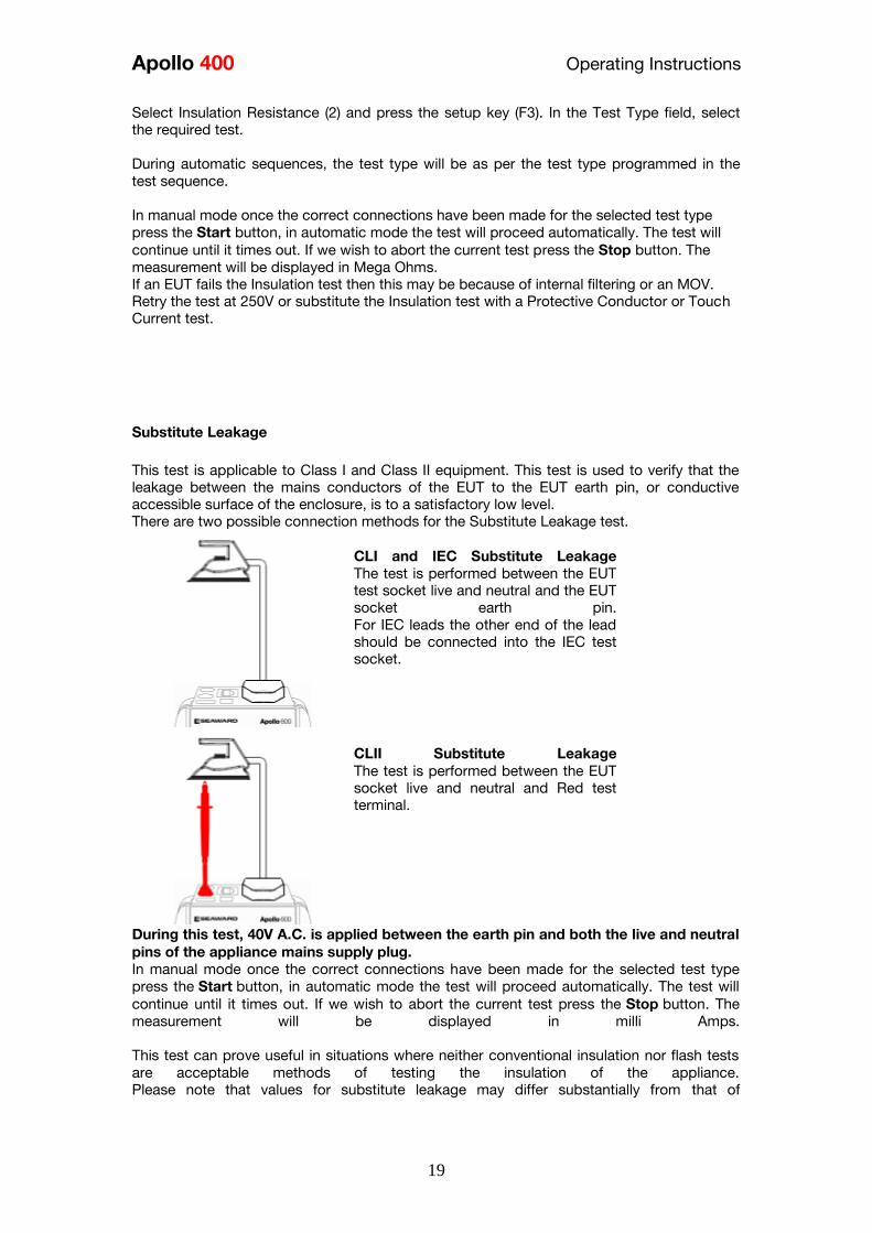
Apollo 400 Operating Instructions
19
Select Insulation Resistance (2) and press the setup key (F3) In the Test Type field select
the required test
During automatic sequences the test type will be as per the test type programmed in the
test sequence
In manual mode once the correct connections have been made for the selected test type
press the Start button in automatic mode the test will proceed automatically The test will
continue until it times out If we wish to abort the current test press the Stop button The
measurement will be displayed in Mega Ohms If an EUT fails the Insulation test then this may be because of internal filtering or an MOV
Retry the test at 250V or substitute the Insulation test with a Protective Conductor or Touch
Current test
Substitute Leakage
This test is applicable to Class I and Class II equipment This test is used to verify that the
leakage between the mains conductors of the EUT to the EUT earth pin or conductive
accessible surface of the enclosure is to a satisfactory low level There are two possible connection methods for the Substitute Leakage test
CLI and IEC Substitute Leakage
The test is performed between the EUT
test socket live and neutral and the EUT
socket earth pin
For IEC leads the other end of the lead
should be connected into the IEC test
socket
CLII Substitute Leakage The test is performed between the EUT
socket live and neutral and Red test
terminal
During this test 40V AC is applied between the earth pin and both the live and neutral
pins of the appliance mains supply plug In manual mode once the correct connections have been made for the selected test type
press the Start button in automatic mode the test will proceed automatically The test will
continue until it times out If we wish to abort the current test press the Stop button The
measurement will be displayed in milli Amps
This test can prove useful in situations where neither conventional insulation nor flash tests
are acceptable methods of testing the insulation of the appliance
Please note that values for substitute leakage may differ substantially from that of
Apollo 400 Operating Instructions
20
conventional earth leakage tests because of the way that the test is performed (eg it will be
affected by the presence of Neutral-to-Earth suppression capacitors)
Protective Earth (PE) Conductor Current
Always test the earth continuity and insulation
resistance before performing a PE Conductor Current
test
Always check that an appliance with moving parts (eg
an electric drill) is safely mounted to avoid risk of
damage to equipment or personnel
Avoid prolonged repeated use at full load (16A) and
excessive test duration as this may reduce the life of the
unit
Always ensure that appliance and leads which include
RCD protection that the RCD is reset at the beginning
of the test Failure to do so may result in incorrect
measurements being recorded
This test is applicable on Class I
Equipment The Apollo 400 should be connected to
a mains supply The EUT should be
connected into the EUT test socket In manual mode once the correct
connections have been made for the
selected test type press
the Start button in automatic mode the
test will proceed automatically
The test will continue until it times out If we wish to abort the current test press
the Stop button The measurement will be displayed in mA Should the test measurement over range then the test will be aborted immediately and a fail
will be logged
Touch Current
Warning Always test the insulation resistance before
performing a Touch Current test
Warning Always check that an appliance with moving
parts (eg an electric drill) is safely mounted to avoid
risk of damage to equipment or personnel
Attention Avoid prolonged repeated use at full load
(16A) and excessive test duration as this may reduce the
life of the unit
Always ensure that appliance and leads which include
RCD protection that the RCD is reset at the beginning
of the test Failure to do so may result in incorrect
measurements being recorded
Apollo 400 Operating Instructions
21
This test is applicable on Class I and
Class II Equipment The Apollo 400 should be connected to
a mains supply The EUT should be
connected into the EUT socket the red
test terminal should be connected to
point at which the leakage measurement
is required
In manual mode once the correct connections have been made for the selected test type
press the Start button in automatic mode the test will proceed automatically The test will
continue until it times out If we wish to abort the current test press the Stop button The
measurement will be displayed in milli Amps Should the test measurement over range then the test will be aborted immediately and a fail
will be logged
RCD Trip Time
Voltages between the protective conductor and earth
may influence measurements This test will pass a sinusoidal current of 30mA between the EUT socket and the IEC socket
and measure the time it takes for the in-line RCD to trip
Remove all other connections before performing an
RCD test
The Apollo 400 should be connected to
a mains supply The RCD should be
plugged into the EUT test socket and a
connection should be made from the
RCD mains output to the IEC test
socket
Once the correct connections have been made for the selected test type press
the Start button The RCD will be powered and you will be prompted to reset the RCD
When you have reset the RCD the Apollo 400 will count down and then perform the RCD
test the RCD trip time will be displayed The measurement will be displayed in milli seconds
IEC Lead Polarity
The IEC lead input is a test socket and is not intended
to be connected directly to mains Do not connect this
input to the mains supply
The Polarity test checks the wiring
polarity of an IEC lead the IEC should
be plugged into both the EUT and IEC
test sockets
This test can be used to test the wiring polarity of extension leads by plugging the supplied
test IEC lead into the end of the extension lead to complete the circuit to the IEC tests
socket In the automatic sequence editor the Polarity can be added to sequence In the manual
mode the polarity test is already part of a pre-defined test sequence which includes an Earth
Continuity test an Insulation test and the Polarity test
External Leakage Adaptors
Apollo 400 Operating Instructions
22
While using an External Leakage Adaptor the mains
supply will be connected to the EUT through the
adaptor
Ensure that when tests are performed using the
external Leakage Adaptor that the Earth Reverse
option is set to Off
The External Leakage Adaptor test
function is intended to used in
conjunction with the one of Seawards
external leakage adaptors Connect the
external leakage adaptor into the Red
test terminal connect the Earth
Continuity probe into the Black test
terminal
Connect the mains supply and the EUT
to the external leakage adaptor
Note that connecting both the EUT and mains supply to the external leakage adaptor will
connect the mains supply to the EUT
114 Checkbox Verification
A checkbox for the Apollo 400 is available as an optional accessory This can be used to
verify that the Apollo 400 test functions are working correctly When selecting the Checkbox
function follow the onscreen instructions
The Checkbox function will perform a number of
electrical tests Ensure that the onscreen instructions
are followed and that you do not touch the checkbox
during the active tests
12 Updating your Firmware
1 Go to wwwseawardcoukfirmware and save the latest Apollo 400 firmware file on
your PC
2 Power on the unit whilst holding down the F1 button
3 Press F2 to update via PC
4 Follow the onscreen instructions
5 Restart the unit
You can check the firmware version of your tester by
pressing this icon in the Home screen
Apollo 400 Operating Instructions
23
13 Electrical Specification
Earth Continuity
Output Current (Load 2Ω)
Test Voltage (oc)
Measuring Range
Display Range
Resolution Operating Error
Number of tests as per IEC61557-
4
+- 200mA DC with ZAP
gt 4VDC
005 Ωndash 1999 Ω
001 Ω ndash 1999 Ω
001 Ω +-5 + 4 counts
approx 1500
Insulation Test
Test Voltages
Test Current
Test Voltage Accuracy
Measuring Range
Display Range
Resolution Operating Error ( lt 10MΩ ) ( gt 10MΩ )
Number of tests as per IEC61557-
2
500V and 250V DC
1mA minimum for a load of
1kohmvolt lt2mA into sc
+20 -0
010M Ω to 1999M Ω
000M Ω to 1999M Ω
001M Ω +-5 +5 counts +-10 +5 counts approx 1500
Subsitute Leakage Test
Test Voltages
Measuring Range
Display Range
Resolution Operating Error
gt25Vac lt50Vac
020mA to 1999mA
000mA to 1999mA
001mA +-10 +2 digits
Protective Conductor Current
Test Voltage
Display Range
Measurement Range
Resolution
Operating Error
Frequency Response
Supply Voltage maximum
load current 16A
001mA to 1999mA
025mA to 1999mA
001mA
+-5 of reading +- 3 digits
40Hz to 25 kHz
Touch Current
Test Voltage
Display Range
Measurement Range
Resolution
Operating Error
Frequency Response
Supply Voltage maximum
load current 16A
000mA to 350mA
010mA to 350mA
001mA
+-5 of reading +- 2 digits
DC to 25 kHz
Apollo 400 Operating Instructions
24
Load PowerCurrent
Test Voltage
Display Range
Measurement Range
Resolution
Operating Error
Supply Voltage maximum
load current 16A
000 - 1600A
050 - 1600A
001A
+-10 of reading +- 5 digits
Lead Test
Test Voltage
Test 5V DC nominal
Live Neutral checks for oc
sc and crossed
Power Socket Test
Input voltage range
195V ndash 253V AC
Indicates configuration of
voltage potential-
Line potential phase to earth
Line potential phase to neutral
Line potential neutral to earth
RCD Test
Test Voltage
Test Current
Test Current Accuracy
Display Range
Measuring Range
Resolution
Operating Error
230V +10 -15
30mA 150mA rms sinusoidal
30mA -10 +0 150mA +10 -0
0 ndash 2000ms
1ms ndash 2000ms
1ms plusmn1ms
External Leakage
Test Voltage
Display Range
Measuring Range
Resolution
Operating Error
Connected to External
Adapter
0mA - 999mA
025mA - 999mA
001mA +-5 of reading +-2 digits
Apollo 400 Operating Instructions
25
14 Useful Information - 141 Factory Set Test Sequences
Test
Visual Earth Continuity Insulation PE Conductor
Current Touch Current
Substitute
Leakage Wiring
RCD
Trip
Time
Name
Duration
(s)
Limit
(ΩΩ) Duration (s) Voltage
Limit
(MΩΩ)
Duration
(s)
Limit
(mA)
Duration
(s)
Limit
(mA)
Duration
(s)
Limit
(mA)
Limit
(ms)
PortableHandheldIT CLI Yes 5 01 2 500 1
PortableHandheldIT CLII Yes 2 500 2
Fixed Appliance CLI Yes 2 01 5 500 1
Fixed Appliance CLII Yes 5 500 2
IEC Lead 2m Yes 5 02 2 500 1 Yes
13A 5m Surge Protected Lead Yes 5 02 2 250 1 Yes
13A 25m Ext Lead 30mA RCD Yes 5 05 5 08 30
Portable CLI PE Current Yes 5 05 2 250 1 5 08
Portable CLII Touch Current Yes 2 250 2 5 03
IT Equip CLI PE Current Yes 5 01 2 250 1 5 35
IT Equip CLII T ouch Current Yes 2 250 5 03
13A 6m Mains Lead Yes 5 02 2 500 1 Yes
13A 12m Mains Lead Yes 5 03 2 500 1 Yes
13A 24m Mains Lead Yes 5 05 2 500 1 Yes
MovStat CLI 500V Insulation Yes 5 01 2 500 1
MovStat CLII 500V Insulation Yes 2 500 2
MovStat CLI PE Current Yes 5 01 2 250 1 5 35
MovStat CLII Touch Current Yes 2 250 2 5 35
110V HandheldPortable CLI Yes 5 01 2 500 1 2 08
110V HandheldPortable CLII Yes 2 500 2 2 03
110V MovableStationary CLI Yes 5 01 2 500 1 2 35
110V MovableStationary CLII Yes 2 500 2 2 03
110V 25m Lead
RpeampInsulation Yes 5 05 2 500 1
Visual Only Yes
Apollo 400 Operating Instructions
26
142 Other Information
Parameter Default Min Max
Earth Continuity PF limit (Ω) 01 001 1999
Earth Continuity Duration (s) 5 2 30
Insulation Resistance PF limit (MΩ) 1 001 1999
Insulation Resistance Duration (s) 5 2 30
Substitute Leakage PF limit (mA) 075 025 15
Substitute Leakage Duration (s) 5 2 30
IEC Cord Earth Continuity PF limit
(ohms) 01 001 5
IEC Cord Insulation PF limit (MΩ) 1 001 1999
Touch Current PF limit (mA) 025 025 350
Touch Current Duration (s) 5 2 30
PE Conductor Current PF limit (mA) 075 025 1999
PE Conductor Current Duration (s) 5 2 30
External Adapter Continuity (Ω) 01 001 5
External Adapter Leakage (mA) 075 025 999
External Adapter Duration (s) 5 2 30
RCD 30mA trip time (ms) 200 1 2000
RCD 150mA trip time (ms) 40 1 40
Number of tests in a test sequence 1 60
Characters in a test sequence name 1 30
Characters in a User Test name 1 15
Characters in a User Test Unit 15
Total number of Test Sequences 25
Test Results (typical) 2000
Sites 50
Characters in Site name 1 15
Locations 50
Characters in Location name 1 15
Users (including admin) 2
Characters in User name 1 15
Comments List 50
Characters in Comment 25
Characters in Asset ID 1 15
Apollo 400 Operating Instructions
27
15 Environmental Conditions
The Apollo 400 has been designed to perform tests and measurements in a dry environment
Maximum barometric elevation for making measurements is 2000M
Pollution degree 2 according to IEC 60529
Electromagnetic compatibility (EMC) Interference immunity and emitted interference
conforming to IEC 61326-1
Operating temperature range of 0 to 40 degrees C without moisture condensation
Operating Altitude 0 to 2000 metres
16 Maintenance
161 Charging the battery pack
The battery pack will be charged whenever the Apollo 400 is connected to the mains supply
regardless of whether it is switched on or off
The typical charging current is set to 500mA but this may vary as the instrument also
includes pre-charge and top up charge modes
When no tests are being performed the battery pack will be fully re-charged after 7 hours
162 Securing the Apollo 400
Under certain conditions safe operation of the Apollo 400 can no longer be assumed
Visible damage of the instrument case
Incorrect measurement results
Recognisable abuse to the instrument due to prolonged storage under improper conditions
Recognisable abuse to the instrument due to extraordinary transportation stress
In these case the Apollo 400 should be immediately switched off disconnected from any test
and measurement function and secured to prevent any further use
163 Cleaning the Apollo 400
Clean the external case of the Apollo 400 with a dry clean cloth
Avoid using solvents and abrasive scouring agents to clean the external case of the Apollo
400
Apollo 400 Operating Instructions
28
164 Replacing the battery pack
Before opening the Apollo 400 battery compartment
ensure that all test leads and accessories are
disconnected
Power off the instrument
Disconnect all test leads and accessories
Position the instrument face down and remove the screw holding the battery compartment
cover in place
Remove the battery compartment cover
Remove the battery pack from the compartment and unplug the 4 way connector
Connect the 4 way connector of the new battery to the 4 way header in the battery
compartment put the battery pack into the compartment
Relocate the battery compartment cover and fasten in position with the battery compartment
screw
ONLY USE A REPLACEMENT BATTERY PACK THAT HAS BEEN SUPPLIED BY SEAWARD
OR A SEAWARD APPROVED DISTRIBUTOR
17 Support
The Apollo 400 must be registered with Seaward before support will be made available For Technical Support contact Tel (+44) 191 587 8718
For help or advice on Service and Calibration contact
CalibrationHouse Seaward Electronic Bracken Hill South West Industrial Estate Peterlee Co Durham SR8 2SW England Tel (+44) 191 5878739 (+44) 191 5878737 Email serviceseawardcouk
Calibration House is part of the Seaward Group
Apollo 400 Operating Instructions
29
171 Register your product here-
wwwseawardcouk 172 Calibration Services-
wwwcalibrationhousecouk Bracken Hill South West Industrial Estate Peterlee County Durham SR8 2SW Co Durham SR8 2SW England Tel (+44) 191 5863511 Some icons provided by Fat Cow (httpwwwfatcowcomfree-icons) Based in part on the work of the Qwt project (httpqwtsfnet)
Apollo 400A simple no-nonsense PAT tester with fast data entry and storage for up to 2000appliance records
Key Featuresn High definition colour displayn Store 2000 appliance recordsn Remote data transfer from field to office n Bluetooth connectivity
Electrical Test Functionsn Low current earth continuity test guaranteeing accurate measurement n Point to point testing (earth continuity and insulation resistance)n Insulation resistancen IEC lead testn Protective conductor currentn Touch currentn Load powercurrentn Alternative leakage currentn RCD testn Power socket test
Ideal Forn Electrical Contractorsn Facilities Managersn Operations Managers
Apollo 400 offers simple electrical safety testing with straightforward data entryusing the intuitive QWERTY keypad
A comprehensive range of electrical safety tests ensure compliance with theIET 4th Edition Code of Practice whilst remote data transfer and USB downloadmakes data management easy and efficient
The Apollo 400 is ideal for mid-volume PAT testing where detailed records arerequired
Streamline the PAT testing process further by using the Apollo 400 with acompatible label printer barcode scanner and PATGuard 3 software
wwwseawardcoukapollo400
Tel +44 (0) 191 587 8741Email salesseawardcouk
Requires optional accessory (part number 380A983)
Straightforward PAT testing with simple data managementApollo 400 offers a comprehensive suite of electrical safetytests to enable any workplace appliance to be tested including3-phase equipment fixed appliances and RCDs
The QWERTY keypad enables asset information to be entered quicklyand easily while a large colour display with an intuitive menu structure makesthe Apollo 400 simple to grasp Lightweight and small in size with battery or mainspower modes the Apollo 400 is good to go in seconds allowing more appliances to betested without downtime for boot-up or a battery re-charge
Superb software for total traceabilityApollo 400 has an internal memory capable of storing up to 2000electrical test records Its compatibility with Seawardrsquos PATGuard 3software means that complete test records are easily managed ona PC
Transfer data to the PC remotely using the Bluetooth function anda smartphone or download the results via a USB cable directly toa PC Once downloaded to PATGuard 3 it is easy to keep track ofthe history of test and inspections as well as produce reportscertificates and invoices ndash offering total peace of mind and quickereasier management of scheduling inspections and tests
Download a free trial at wwwseawardcoukpg3trial
wwwseawardcoukapollo400
Tel +44 (0) 191 587 8741Email salesseawardcouk
additional accessory required for point to point testing
u Accessory BundlesThe Apollo 400 is available to buy with a selectionof optional accessory bundles to help you get themost out of your tester
Apollo 400 is supplied as standard with a UKAScalibration certificate and a 2 yearmanufacturerrsquos warranty (subject to terms andconditions)
Greater efficiency through useful accessoriesAs with many Seaward PAT testers the Apollo 400 is compatible with arange of printers and barcode scanners further speeding up the processof asset recognition testing and labelling
Also available in this range
A multi-tasking and fully customisable PAT with additionalhealth and safety features and on-board camera forunrivalled record keeping
Apollo 600 includes a universal risk assessment tool andthe ability to store up to 50000 appliance records plus2000 images - providing visual evidence of testenvironments perfect for advanced record-keeping inorganisations with high-volume workplace test andinspection routines
Apollo 600Multi-tasking PAT tester with on-board camera
wwwseawardcoukapollo400
Tel +44 (0) 191 587 8741Email salesseawardcouk
A powerful PAT tester with a built-in PAT retest calculatorand flexible user-configurable sequences for recordingany non-electrical workplace test or inspection
The ability to customise a number of settings and a largememory to store up to 10000 appliance records makesthe Apollo 500 a versatile and dependable tool for highvolume PAT testing
Apollo 500A fast amp fully customisable and versatile PAT tester
Optional accessory bundles available Part Number
Elite Bundle n Test n Tag Elite 2 rugged portable printer
n Test n Tag printer labels x 4
n Bluetooth barcode scanner
n Apollo kit carry case
n 110V adapter
Includes Apollo 400 tester
380A978
Elite Bundle +Software
PLUS PATGuard 3 software 1yr licence 380A979
Pro Bundle n Test n Tag Pro lightweight portable printer
n Test n Tag printer labels x 4
n Bluetooth barcode scanner
n Apollo kit carry case
n 110V adapter
Includes Apollo 400 tester
380A980
Pro Bundle +Software PLUS PATGuard 3 software 1yr licence 380A981
wwwseawardcoukapollo400
Tel +44 (0) 191 587 8741Email salesseawardcouk
Apollo 400 Apollo 500 Apollo 600
General Features
Battery amp mains powered n n n
Colour Screen amp QWERTY keypad n n n
Large internal memory 2000 records 10000 records 50000 records
Scanner amp printer compatible n n n
Password controlled user accounts n n
Set up multiple user accounts with varyinglevels of privileges
n n
Clone facility to set up multiple testers n n
Checkbox supplied as standard n n
On-board user manual n n
Test amp InspectionFeatures
Auto-increment asset ID n n
PAT Setup option to allow for custom menus n n
Enter asset description after test usingkeypad or barcode scanner
n n n
Comprehensive electrical safety test features n n n
Point to point measurement (Rpe amp IR)
n
(optional
accessory
required)
n n
User configurable electrical testvisualinspection sequences 25 100 100
User set sites amp locations 50 100 100
Risk based retest period calculator n n
User definable comments lines against testrecords
n n
Configurable checklists for any workplacetest or inspection (user tests)
n n
On-board camera n
Universal risk assessment n
Health amp safety certificates n
Data Transfer
Bluetooth connectivity n n n
Barcode scanner connectivity n n n
Print Pass amp Fail labels n n n
Add your company logo to labels n n
Select from various label formats to print n n
Remote data transfer via mobile device n
(Android only)
n
(Android only)
n
(Android and iOS)
Download to PC via USB cable n n n
Filter results to be downloaded n n
Upload previous results to tester for retest n n
Data transfer via USB flash drive n
Apollo Series Comparison Chart
PAT TESTS
Earth ContinuityTest Current +- 200mA DC Display Range 001 ndash 1999ΩPass Value User Defined
Insulation ResistanceTest Voltage 500V 250VDC 1mA nominalDisplay Range 001MΩ - 1999MΩPass Value User Defined
IEC Lead TestTest Voltage 5VAC nominalTest Live Neutral Checks for oc sc and crossed
Protective Conductor CurrentLoad
Test Voltage Supply voltage maximum load current 16A Display Ranges 001mA to 1999mA Pass Value User Defined
Touch Current
Test Voltage Supply Voltage maximum load current 16ADisplay Range 000 ndash 350mA Pass Value User defined
Load PowerCurrent
Test Voltage Supply Voltage maximum load current 16ATest Duration Programmable up to a maximum of 255s depending on load ie max duration is reduced for high loadsDisplay Range 000kVA ndash 400kVA 000A ndash 1600A
Alternative Leakage Current
Test Voltages gt25VAC lt50VAC Display Range 000mA to 1999mAPass Value User Defined
RCD Test
Test Voltage 230V +10 -15Test Current 30mA 150mA rms sinusoidalDisplay Range 0ms - 2000ms (30mA) 0-40ms (150mA)Test Method Internal isolation to avoid tripping distribution board RCD
Power Socket Test
Voltage Range 207V ndash 253VACIndicates configuration of voltage potential-Line potential phase to earthLine potential phase to neutralLine potential neutral to earth
General
Memory Size 2000 recordsWeight 15kgDimensions 230mm x 150mm x 100mmPower Source Mains or rechargeable battery pack
Standard Accessories (supplied with Apollo 400)30 day free trial of PATGuard 3 software 1x red test lead and probe with crocodile clip05m IEC leadMains power leadUSB download cableQuick start guideUKAS calibration certificate
Optional Accessories Test n Tag Elite 2 Bluetooth printer with roll of small labels (339A995)Test n Tag Pro Bluetooth printer with roll of small labels (339A987)Roll of small labels (approx 350 off 52 x 25mm labels) (339A947)Additional black test lead and probe with crocodile clip (for point to point testing) (380A983)Bluetooth barcode scanner (339A923)110V test adaptor (270A076)110V to IEC adapter (344A050)Apollo checkbox (380A953)3 Phase Leakage Adaptor 5 Star 16A (391A920)3 Phase Leakage Adaptor 5 Star 32A (391A910)3 Phase Adapter Delta 4 pin 16A 415V (for Rpe amp IR) (209A910)3 Phase Adapter Star 5 pin 16A 415V (for Rpe amp IR) (209A911)3 Phase Adapter Delta 4 pin 32A 415V (for Rpe amp IR) (209A912)3 Phase Adapter Star 5 pin 32A 415V (for Rpe amp IR) (209A913)Professional Seaward kit bag (71G109)Apollo carry case (380A952)PATGuard 3 software ndash download 30 day free trial atwwwseawardcoukpg3trial
Part NumbersApollo 400 standard package 380A920Apollo 400 with Elite accessory bundle 380A978Apollo 400 with Elite accessory bundle amp PATGuard 3 one year licence380A979Apollo 400 with Pro accessory bundle 380A980Apollo 400 with Pro accessory bundle amp PATGuard 3 one year licence380A981
TrainingSeaward offer a range of PAT testing courses including City amp GuildsGo to wwwseawardcouktraining for more information
Services2 year warranty (subject to terms and conditions available atwwwseawardcoukwarranty24)Service amp Calibration by CalibrationhouseGo to wwwcalibrationhousecom for more information
Technical Specifications
Part of
Rev 12
wwwseawardcoukapollo400
Tel +44 (0) 191 587 8741Email salesseawardcouk
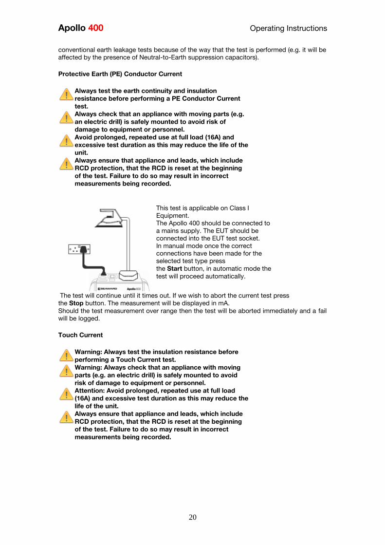
Apollo 400 Operating Instructions
20
conventional earth leakage tests because of the way that the test is performed (eg it will be
affected by the presence of Neutral-to-Earth suppression capacitors)
Protective Earth (PE) Conductor Current
Always test the earth continuity and insulation
resistance before performing a PE Conductor Current
test
Always check that an appliance with moving parts (eg
an electric drill) is safely mounted to avoid risk of
damage to equipment or personnel
Avoid prolonged repeated use at full load (16A) and
excessive test duration as this may reduce the life of the
unit
Always ensure that appliance and leads which include
RCD protection that the RCD is reset at the beginning
of the test Failure to do so may result in incorrect
measurements being recorded
This test is applicable on Class I
Equipment The Apollo 400 should be connected to
a mains supply The EUT should be
connected into the EUT test socket In manual mode once the correct
connections have been made for the
selected test type press
the Start button in automatic mode the
test will proceed automatically
The test will continue until it times out If we wish to abort the current test press
the Stop button The measurement will be displayed in mA Should the test measurement over range then the test will be aborted immediately and a fail
will be logged
Touch Current
Warning Always test the insulation resistance before
performing a Touch Current test
Warning Always check that an appliance with moving
parts (eg an electric drill) is safely mounted to avoid
risk of damage to equipment or personnel
Attention Avoid prolonged repeated use at full load
(16A) and excessive test duration as this may reduce the
life of the unit
Always ensure that appliance and leads which include
RCD protection that the RCD is reset at the beginning
of the test Failure to do so may result in incorrect
measurements being recorded
Apollo 400 Operating Instructions
21
This test is applicable on Class I and
Class II Equipment The Apollo 400 should be connected to
a mains supply The EUT should be
connected into the EUT socket the red
test terminal should be connected to
point at which the leakage measurement
is required
In manual mode once the correct connections have been made for the selected test type
press the Start button in automatic mode the test will proceed automatically The test will
continue until it times out If we wish to abort the current test press the Stop button The
measurement will be displayed in milli Amps Should the test measurement over range then the test will be aborted immediately and a fail
will be logged
RCD Trip Time
Voltages between the protective conductor and earth
may influence measurements This test will pass a sinusoidal current of 30mA between the EUT socket and the IEC socket
and measure the time it takes for the in-line RCD to trip
Remove all other connections before performing an
RCD test
The Apollo 400 should be connected to
a mains supply The RCD should be
plugged into the EUT test socket and a
connection should be made from the
RCD mains output to the IEC test
socket
Once the correct connections have been made for the selected test type press
the Start button The RCD will be powered and you will be prompted to reset the RCD
When you have reset the RCD the Apollo 400 will count down and then perform the RCD
test the RCD trip time will be displayed The measurement will be displayed in milli seconds
IEC Lead Polarity
The IEC lead input is a test socket and is not intended
to be connected directly to mains Do not connect this
input to the mains supply
The Polarity test checks the wiring
polarity of an IEC lead the IEC should
be plugged into both the EUT and IEC
test sockets
This test can be used to test the wiring polarity of extension leads by plugging the supplied
test IEC lead into the end of the extension lead to complete the circuit to the IEC tests
socket In the automatic sequence editor the Polarity can be added to sequence In the manual
mode the polarity test is already part of a pre-defined test sequence which includes an Earth
Continuity test an Insulation test and the Polarity test
External Leakage Adaptors
Apollo 400 Operating Instructions
22
While using an External Leakage Adaptor the mains
supply will be connected to the EUT through the
adaptor
Ensure that when tests are performed using the
external Leakage Adaptor that the Earth Reverse
option is set to Off
The External Leakage Adaptor test
function is intended to used in
conjunction with the one of Seawards
external leakage adaptors Connect the
external leakage adaptor into the Red
test terminal connect the Earth
Continuity probe into the Black test
terminal
Connect the mains supply and the EUT
to the external leakage adaptor
Note that connecting both the EUT and mains supply to the external leakage adaptor will
connect the mains supply to the EUT
114 Checkbox Verification
A checkbox for the Apollo 400 is available as an optional accessory This can be used to
verify that the Apollo 400 test functions are working correctly When selecting the Checkbox
function follow the onscreen instructions
The Checkbox function will perform a number of
electrical tests Ensure that the onscreen instructions
are followed and that you do not touch the checkbox
during the active tests
12 Updating your Firmware
1 Go to wwwseawardcoukfirmware and save the latest Apollo 400 firmware file on
your PC
2 Power on the unit whilst holding down the F1 button
3 Press F2 to update via PC
4 Follow the onscreen instructions
5 Restart the unit
You can check the firmware version of your tester by
pressing this icon in the Home screen
Apollo 400 Operating Instructions
23
13 Electrical Specification
Earth Continuity
Output Current (Load 2Ω)
Test Voltage (oc)
Measuring Range
Display Range
Resolution Operating Error
Number of tests as per IEC61557-
4
+- 200mA DC with ZAP
gt 4VDC
005 Ωndash 1999 Ω
001 Ω ndash 1999 Ω
001 Ω +-5 + 4 counts
approx 1500
Insulation Test
Test Voltages
Test Current
Test Voltage Accuracy
Measuring Range
Display Range
Resolution Operating Error ( lt 10MΩ ) ( gt 10MΩ )
Number of tests as per IEC61557-
2
500V and 250V DC
1mA minimum for a load of
1kohmvolt lt2mA into sc
+20 -0
010M Ω to 1999M Ω
000M Ω to 1999M Ω
001M Ω +-5 +5 counts +-10 +5 counts approx 1500
Subsitute Leakage Test
Test Voltages
Measuring Range
Display Range
Resolution Operating Error
gt25Vac lt50Vac
020mA to 1999mA
000mA to 1999mA
001mA +-10 +2 digits
Protective Conductor Current
Test Voltage
Display Range
Measurement Range
Resolution
Operating Error
Frequency Response
Supply Voltage maximum
load current 16A
001mA to 1999mA
025mA to 1999mA
001mA
+-5 of reading +- 3 digits
40Hz to 25 kHz
Touch Current
Test Voltage
Display Range
Measurement Range
Resolution
Operating Error
Frequency Response
Supply Voltage maximum
load current 16A
000mA to 350mA
010mA to 350mA
001mA
+-5 of reading +- 2 digits
DC to 25 kHz
Apollo 400 Operating Instructions
24
Load PowerCurrent
Test Voltage
Display Range
Measurement Range
Resolution
Operating Error
Supply Voltage maximum
load current 16A
000 - 1600A
050 - 1600A
001A
+-10 of reading +- 5 digits
Lead Test
Test Voltage
Test 5V DC nominal
Live Neutral checks for oc
sc and crossed
Power Socket Test
Input voltage range
195V ndash 253V AC
Indicates configuration of
voltage potential-
Line potential phase to earth
Line potential phase to neutral
Line potential neutral to earth
RCD Test
Test Voltage
Test Current
Test Current Accuracy
Display Range
Measuring Range
Resolution
Operating Error
230V +10 -15
30mA 150mA rms sinusoidal
30mA -10 +0 150mA +10 -0
0 ndash 2000ms
1ms ndash 2000ms
1ms plusmn1ms
External Leakage
Test Voltage
Display Range
Measuring Range
Resolution
Operating Error
Connected to External
Adapter
0mA - 999mA
025mA - 999mA
001mA +-5 of reading +-2 digits
Apollo 400 Operating Instructions
25
14 Useful Information - 141 Factory Set Test Sequences
Test
Visual Earth Continuity Insulation PE Conductor
Current Touch Current
Substitute
Leakage Wiring
RCD
Trip
Time
Name
Duration
(s)
Limit
(ΩΩ) Duration (s) Voltage
Limit
(MΩΩ)
Duration
(s)
Limit
(mA)
Duration
(s)
Limit
(mA)
Duration
(s)
Limit
(mA)
Limit
(ms)
PortableHandheldIT CLI Yes 5 01 2 500 1
PortableHandheldIT CLII Yes 2 500 2
Fixed Appliance CLI Yes 2 01 5 500 1
Fixed Appliance CLII Yes 5 500 2
IEC Lead 2m Yes 5 02 2 500 1 Yes
13A 5m Surge Protected Lead Yes 5 02 2 250 1 Yes
13A 25m Ext Lead 30mA RCD Yes 5 05 5 08 30
Portable CLI PE Current Yes 5 05 2 250 1 5 08
Portable CLII Touch Current Yes 2 250 2 5 03
IT Equip CLI PE Current Yes 5 01 2 250 1 5 35
IT Equip CLII T ouch Current Yes 2 250 5 03
13A 6m Mains Lead Yes 5 02 2 500 1 Yes
13A 12m Mains Lead Yes 5 03 2 500 1 Yes
13A 24m Mains Lead Yes 5 05 2 500 1 Yes
MovStat CLI 500V Insulation Yes 5 01 2 500 1
MovStat CLII 500V Insulation Yes 2 500 2
MovStat CLI PE Current Yes 5 01 2 250 1 5 35
MovStat CLII Touch Current Yes 2 250 2 5 35
110V HandheldPortable CLI Yes 5 01 2 500 1 2 08
110V HandheldPortable CLII Yes 2 500 2 2 03
110V MovableStationary CLI Yes 5 01 2 500 1 2 35
110V MovableStationary CLII Yes 2 500 2 2 03
110V 25m Lead
RpeampInsulation Yes 5 05 2 500 1
Visual Only Yes
Apollo 400 Operating Instructions
26
142 Other Information
Parameter Default Min Max
Earth Continuity PF limit (Ω) 01 001 1999
Earth Continuity Duration (s) 5 2 30
Insulation Resistance PF limit (MΩ) 1 001 1999
Insulation Resistance Duration (s) 5 2 30
Substitute Leakage PF limit (mA) 075 025 15
Substitute Leakage Duration (s) 5 2 30
IEC Cord Earth Continuity PF limit
(ohms) 01 001 5
IEC Cord Insulation PF limit (MΩ) 1 001 1999
Touch Current PF limit (mA) 025 025 350
Touch Current Duration (s) 5 2 30
PE Conductor Current PF limit (mA) 075 025 1999
PE Conductor Current Duration (s) 5 2 30
External Adapter Continuity (Ω) 01 001 5
External Adapter Leakage (mA) 075 025 999
External Adapter Duration (s) 5 2 30
RCD 30mA trip time (ms) 200 1 2000
RCD 150mA trip time (ms) 40 1 40
Number of tests in a test sequence 1 60
Characters in a test sequence name 1 30
Characters in a User Test name 1 15
Characters in a User Test Unit 15
Total number of Test Sequences 25
Test Results (typical) 2000
Sites 50
Characters in Site name 1 15
Locations 50
Characters in Location name 1 15
Users (including admin) 2
Characters in User name 1 15
Comments List 50
Characters in Comment 25
Characters in Asset ID 1 15
Apollo 400 Operating Instructions
27
15 Environmental Conditions
The Apollo 400 has been designed to perform tests and measurements in a dry environment
Maximum barometric elevation for making measurements is 2000M
Pollution degree 2 according to IEC 60529
Electromagnetic compatibility (EMC) Interference immunity and emitted interference
conforming to IEC 61326-1
Operating temperature range of 0 to 40 degrees C without moisture condensation
Operating Altitude 0 to 2000 metres
16 Maintenance
161 Charging the battery pack
The battery pack will be charged whenever the Apollo 400 is connected to the mains supply
regardless of whether it is switched on or off
The typical charging current is set to 500mA but this may vary as the instrument also
includes pre-charge and top up charge modes
When no tests are being performed the battery pack will be fully re-charged after 7 hours
162 Securing the Apollo 400
Under certain conditions safe operation of the Apollo 400 can no longer be assumed
Visible damage of the instrument case
Incorrect measurement results
Recognisable abuse to the instrument due to prolonged storage under improper conditions
Recognisable abuse to the instrument due to extraordinary transportation stress
In these case the Apollo 400 should be immediately switched off disconnected from any test
and measurement function and secured to prevent any further use
163 Cleaning the Apollo 400
Clean the external case of the Apollo 400 with a dry clean cloth
Avoid using solvents and abrasive scouring agents to clean the external case of the Apollo
400
Apollo 400 Operating Instructions
28
164 Replacing the battery pack
Before opening the Apollo 400 battery compartment
ensure that all test leads and accessories are
disconnected
Power off the instrument
Disconnect all test leads and accessories
Position the instrument face down and remove the screw holding the battery compartment
cover in place
Remove the battery compartment cover
Remove the battery pack from the compartment and unplug the 4 way connector
Connect the 4 way connector of the new battery to the 4 way header in the battery
compartment put the battery pack into the compartment
Relocate the battery compartment cover and fasten in position with the battery compartment
screw
ONLY USE A REPLACEMENT BATTERY PACK THAT HAS BEEN SUPPLIED BY SEAWARD
OR A SEAWARD APPROVED DISTRIBUTOR
17 Support
The Apollo 400 must be registered with Seaward before support will be made available For Technical Support contact Tel (+44) 191 587 8718
For help or advice on Service and Calibration contact
CalibrationHouse Seaward Electronic Bracken Hill South West Industrial Estate Peterlee Co Durham SR8 2SW England Tel (+44) 191 5878739 (+44) 191 5878737 Email serviceseawardcouk
Calibration House is part of the Seaward Group
Apollo 400 Operating Instructions
29
171 Register your product here-
wwwseawardcouk 172 Calibration Services-
wwwcalibrationhousecouk Bracken Hill South West Industrial Estate Peterlee County Durham SR8 2SW Co Durham SR8 2SW England Tel (+44) 191 5863511 Some icons provided by Fat Cow (httpwwwfatcowcomfree-icons) Based in part on the work of the Qwt project (httpqwtsfnet)
Apollo 400A simple no-nonsense PAT tester with fast data entry and storage for up to 2000appliance records
Key Featuresn High definition colour displayn Store 2000 appliance recordsn Remote data transfer from field to office n Bluetooth connectivity
Electrical Test Functionsn Low current earth continuity test guaranteeing accurate measurement n Point to point testing (earth continuity and insulation resistance)n Insulation resistancen IEC lead testn Protective conductor currentn Touch currentn Load powercurrentn Alternative leakage currentn RCD testn Power socket test
Ideal Forn Electrical Contractorsn Facilities Managersn Operations Managers
Apollo 400 offers simple electrical safety testing with straightforward data entryusing the intuitive QWERTY keypad
A comprehensive range of electrical safety tests ensure compliance with theIET 4th Edition Code of Practice whilst remote data transfer and USB downloadmakes data management easy and efficient
The Apollo 400 is ideal for mid-volume PAT testing where detailed records arerequired
Streamline the PAT testing process further by using the Apollo 400 with acompatible label printer barcode scanner and PATGuard 3 software
wwwseawardcoukapollo400
Tel +44 (0) 191 587 8741Email salesseawardcouk
Requires optional accessory (part number 380A983)
Straightforward PAT testing with simple data managementApollo 400 offers a comprehensive suite of electrical safetytests to enable any workplace appliance to be tested including3-phase equipment fixed appliances and RCDs
The QWERTY keypad enables asset information to be entered quicklyand easily while a large colour display with an intuitive menu structure makesthe Apollo 400 simple to grasp Lightweight and small in size with battery or mainspower modes the Apollo 400 is good to go in seconds allowing more appliances to betested without downtime for boot-up or a battery re-charge
Superb software for total traceabilityApollo 400 has an internal memory capable of storing up to 2000electrical test records Its compatibility with Seawardrsquos PATGuard 3software means that complete test records are easily managed ona PC
Transfer data to the PC remotely using the Bluetooth function anda smartphone or download the results via a USB cable directly toa PC Once downloaded to PATGuard 3 it is easy to keep track ofthe history of test and inspections as well as produce reportscertificates and invoices ndash offering total peace of mind and quickereasier management of scheduling inspections and tests
Download a free trial at wwwseawardcoukpg3trial
wwwseawardcoukapollo400
Tel +44 (0) 191 587 8741Email salesseawardcouk
additional accessory required for point to point testing
u Accessory BundlesThe Apollo 400 is available to buy with a selectionof optional accessory bundles to help you get themost out of your tester
Apollo 400 is supplied as standard with a UKAScalibration certificate and a 2 yearmanufacturerrsquos warranty (subject to terms andconditions)
Greater efficiency through useful accessoriesAs with many Seaward PAT testers the Apollo 400 is compatible with arange of printers and barcode scanners further speeding up the processof asset recognition testing and labelling
Also available in this range
A multi-tasking and fully customisable PAT with additionalhealth and safety features and on-board camera forunrivalled record keeping
Apollo 600 includes a universal risk assessment tool andthe ability to store up to 50000 appliance records plus2000 images - providing visual evidence of testenvironments perfect for advanced record-keeping inorganisations with high-volume workplace test andinspection routines
Apollo 600Multi-tasking PAT tester with on-board camera
wwwseawardcoukapollo400
Tel +44 (0) 191 587 8741Email salesseawardcouk
A powerful PAT tester with a built-in PAT retest calculatorand flexible user-configurable sequences for recordingany non-electrical workplace test or inspection
The ability to customise a number of settings and a largememory to store up to 10000 appliance records makesthe Apollo 500 a versatile and dependable tool for highvolume PAT testing
Apollo 500A fast amp fully customisable and versatile PAT tester
Optional accessory bundles available Part Number
Elite Bundle n Test n Tag Elite 2 rugged portable printer
n Test n Tag printer labels x 4
n Bluetooth barcode scanner
n Apollo kit carry case
n 110V adapter
Includes Apollo 400 tester
380A978
Elite Bundle +Software
PLUS PATGuard 3 software 1yr licence 380A979
Pro Bundle n Test n Tag Pro lightweight portable printer
n Test n Tag printer labels x 4
n Bluetooth barcode scanner
n Apollo kit carry case
n 110V adapter
Includes Apollo 400 tester
380A980
Pro Bundle +Software PLUS PATGuard 3 software 1yr licence 380A981
wwwseawardcoukapollo400
Tel +44 (0) 191 587 8741Email salesseawardcouk
Apollo 400 Apollo 500 Apollo 600
General Features
Battery amp mains powered n n n
Colour Screen amp QWERTY keypad n n n
Large internal memory 2000 records 10000 records 50000 records
Scanner amp printer compatible n n n
Password controlled user accounts n n
Set up multiple user accounts with varyinglevels of privileges
n n
Clone facility to set up multiple testers n n
Checkbox supplied as standard n n
On-board user manual n n
Test amp InspectionFeatures
Auto-increment asset ID n n
PAT Setup option to allow for custom menus n n
Enter asset description after test usingkeypad or barcode scanner
n n n
Comprehensive electrical safety test features n n n
Point to point measurement (Rpe amp IR)
n
(optional
accessory
required)
n n
User configurable electrical testvisualinspection sequences 25 100 100
User set sites amp locations 50 100 100
Risk based retest period calculator n n
User definable comments lines against testrecords
n n
Configurable checklists for any workplacetest or inspection (user tests)
n n
On-board camera n
Universal risk assessment n
Health amp safety certificates n
Data Transfer
Bluetooth connectivity n n n
Barcode scanner connectivity n n n
Print Pass amp Fail labels n n n
Add your company logo to labels n n
Select from various label formats to print n n
Remote data transfer via mobile device n
(Android only)
n
(Android only)
n
(Android and iOS)
Download to PC via USB cable n n n
Filter results to be downloaded n n
Upload previous results to tester for retest n n
Data transfer via USB flash drive n
Apollo Series Comparison Chart
PAT TESTS
Earth ContinuityTest Current +- 200mA DC Display Range 001 ndash 1999ΩPass Value User Defined
Insulation ResistanceTest Voltage 500V 250VDC 1mA nominalDisplay Range 001MΩ - 1999MΩPass Value User Defined
IEC Lead TestTest Voltage 5VAC nominalTest Live Neutral Checks for oc sc and crossed
Protective Conductor CurrentLoad
Test Voltage Supply voltage maximum load current 16A Display Ranges 001mA to 1999mA Pass Value User Defined
Touch Current
Test Voltage Supply Voltage maximum load current 16ADisplay Range 000 ndash 350mA Pass Value User defined
Load PowerCurrent
Test Voltage Supply Voltage maximum load current 16ATest Duration Programmable up to a maximum of 255s depending on load ie max duration is reduced for high loadsDisplay Range 000kVA ndash 400kVA 000A ndash 1600A
Alternative Leakage Current
Test Voltages gt25VAC lt50VAC Display Range 000mA to 1999mAPass Value User Defined
RCD Test
Test Voltage 230V +10 -15Test Current 30mA 150mA rms sinusoidalDisplay Range 0ms - 2000ms (30mA) 0-40ms (150mA)Test Method Internal isolation to avoid tripping distribution board RCD
Power Socket Test
Voltage Range 207V ndash 253VACIndicates configuration of voltage potential-Line potential phase to earthLine potential phase to neutralLine potential neutral to earth
General
Memory Size 2000 recordsWeight 15kgDimensions 230mm x 150mm x 100mmPower Source Mains or rechargeable battery pack
Standard Accessories (supplied with Apollo 400)30 day free trial of PATGuard 3 software 1x red test lead and probe with crocodile clip05m IEC leadMains power leadUSB download cableQuick start guideUKAS calibration certificate
Optional Accessories Test n Tag Elite 2 Bluetooth printer with roll of small labels (339A995)Test n Tag Pro Bluetooth printer with roll of small labels (339A987)Roll of small labels (approx 350 off 52 x 25mm labels) (339A947)Additional black test lead and probe with crocodile clip (for point to point testing) (380A983)Bluetooth barcode scanner (339A923)110V test adaptor (270A076)110V to IEC adapter (344A050)Apollo checkbox (380A953)3 Phase Leakage Adaptor 5 Star 16A (391A920)3 Phase Leakage Adaptor 5 Star 32A (391A910)3 Phase Adapter Delta 4 pin 16A 415V (for Rpe amp IR) (209A910)3 Phase Adapter Star 5 pin 16A 415V (for Rpe amp IR) (209A911)3 Phase Adapter Delta 4 pin 32A 415V (for Rpe amp IR) (209A912)3 Phase Adapter Star 5 pin 32A 415V (for Rpe amp IR) (209A913)Professional Seaward kit bag (71G109)Apollo carry case (380A952)PATGuard 3 software ndash download 30 day free trial atwwwseawardcoukpg3trial
Part NumbersApollo 400 standard package 380A920Apollo 400 with Elite accessory bundle 380A978Apollo 400 with Elite accessory bundle amp PATGuard 3 one year licence380A979Apollo 400 with Pro accessory bundle 380A980Apollo 400 with Pro accessory bundle amp PATGuard 3 one year licence380A981
TrainingSeaward offer a range of PAT testing courses including City amp GuildsGo to wwwseawardcouktraining for more information
Services2 year warranty (subject to terms and conditions available atwwwseawardcoukwarranty24)Service amp Calibration by CalibrationhouseGo to wwwcalibrationhousecom for more information
Technical Specifications
Part of
Rev 12
wwwseawardcoukapollo400
Tel +44 (0) 191 587 8741Email salesseawardcouk
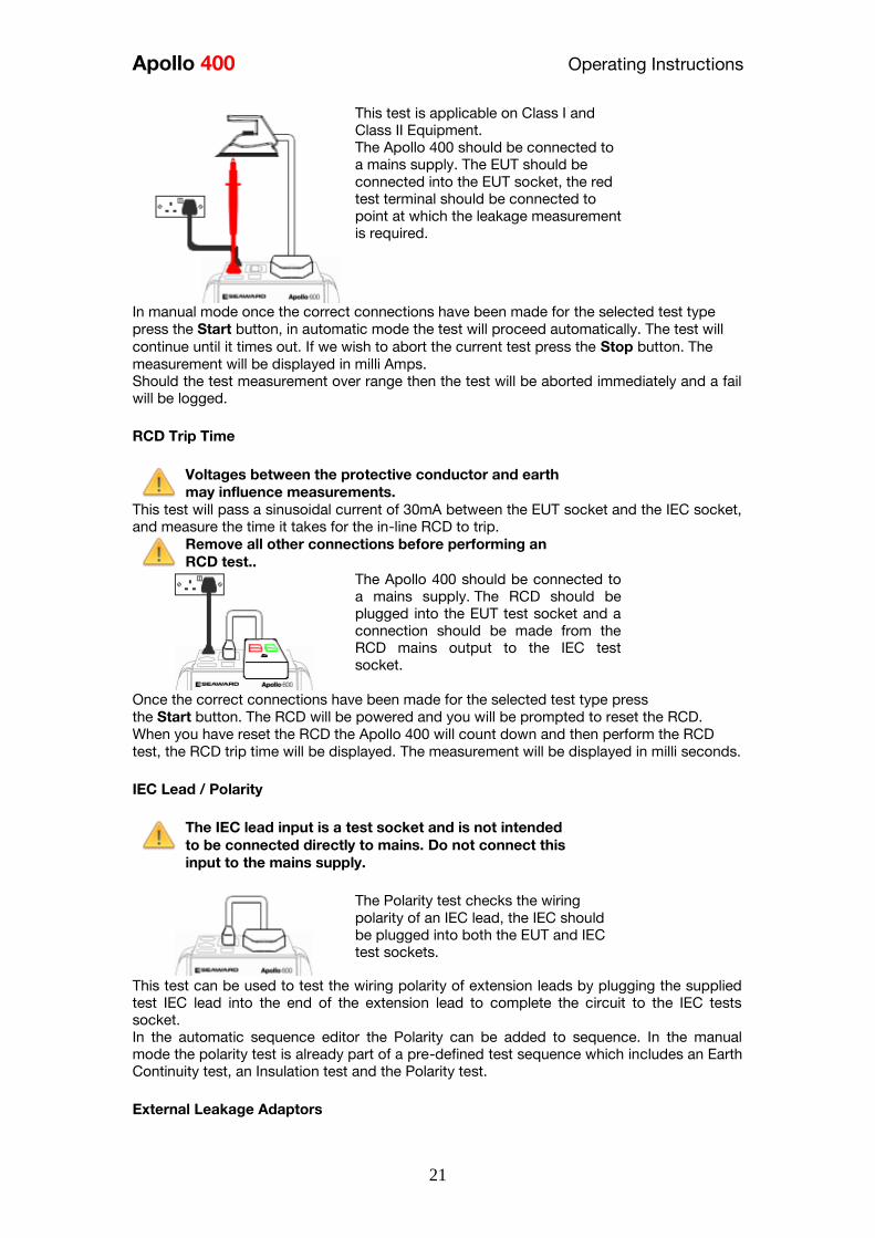
Apollo 400 Operating Instructions
21
This test is applicable on Class I and
Class II Equipment The Apollo 400 should be connected to
a mains supply The EUT should be
connected into the EUT socket the red
test terminal should be connected to
point at which the leakage measurement
is required
In manual mode once the correct connections have been made for the selected test type
press the Start button in automatic mode the test will proceed automatically The test will
continue until it times out If we wish to abort the current test press the Stop button The
measurement will be displayed in milli Amps Should the test measurement over range then the test will be aborted immediately and a fail
will be logged
RCD Trip Time
Voltages between the protective conductor and earth
may influence measurements This test will pass a sinusoidal current of 30mA between the EUT socket and the IEC socket
and measure the time it takes for the in-line RCD to trip
Remove all other connections before performing an
RCD test
The Apollo 400 should be connected to
a mains supply The RCD should be
plugged into the EUT test socket and a
connection should be made from the
RCD mains output to the IEC test
socket
Once the correct connections have been made for the selected test type press
the Start button The RCD will be powered and you will be prompted to reset the RCD
When you have reset the RCD the Apollo 400 will count down and then perform the RCD
test the RCD trip time will be displayed The measurement will be displayed in milli seconds
IEC Lead Polarity
The IEC lead input is a test socket and is not intended
to be connected directly to mains Do not connect this
input to the mains supply
The Polarity test checks the wiring
polarity of an IEC lead the IEC should
be plugged into both the EUT and IEC
test sockets
This test can be used to test the wiring polarity of extension leads by plugging the supplied
test IEC lead into the end of the extension lead to complete the circuit to the IEC tests
socket In the automatic sequence editor the Polarity can be added to sequence In the manual
mode the polarity test is already part of a pre-defined test sequence which includes an Earth
Continuity test an Insulation test and the Polarity test
External Leakage Adaptors
Apollo 400 Operating Instructions
22
While using an External Leakage Adaptor the mains
supply will be connected to the EUT through the
adaptor
Ensure that when tests are performed using the
external Leakage Adaptor that the Earth Reverse
option is set to Off
The External Leakage Adaptor test
function is intended to used in
conjunction with the one of Seawards
external leakage adaptors Connect the
external leakage adaptor into the Red
test terminal connect the Earth
Continuity probe into the Black test
terminal
Connect the mains supply and the EUT
to the external leakage adaptor
Note that connecting both the EUT and mains supply to the external leakage adaptor will
connect the mains supply to the EUT
114 Checkbox Verification
A checkbox for the Apollo 400 is available as an optional accessory This can be used to
verify that the Apollo 400 test functions are working correctly When selecting the Checkbox
function follow the onscreen instructions
The Checkbox function will perform a number of
electrical tests Ensure that the onscreen instructions
are followed and that you do not touch the checkbox
during the active tests
12 Updating your Firmware
1 Go to wwwseawardcoukfirmware and save the latest Apollo 400 firmware file on
your PC
2 Power on the unit whilst holding down the F1 button
3 Press F2 to update via PC
4 Follow the onscreen instructions
5 Restart the unit
You can check the firmware version of your tester by
pressing this icon in the Home screen
Apollo 400 Operating Instructions
23
13 Electrical Specification
Earth Continuity
Output Current (Load 2Ω)
Test Voltage (oc)
Measuring Range
Display Range
Resolution Operating Error
Number of tests as per IEC61557-
4
+- 200mA DC with ZAP
gt 4VDC
005 Ωndash 1999 Ω
001 Ω ndash 1999 Ω
001 Ω +-5 + 4 counts
approx 1500
Insulation Test
Test Voltages
Test Current
Test Voltage Accuracy
Measuring Range
Display Range
Resolution Operating Error ( lt 10MΩ ) ( gt 10MΩ )
Number of tests as per IEC61557-
2
500V and 250V DC
1mA minimum for a load of
1kohmvolt lt2mA into sc
+20 -0
010M Ω to 1999M Ω
000M Ω to 1999M Ω
001M Ω +-5 +5 counts +-10 +5 counts approx 1500
Subsitute Leakage Test
Test Voltages
Measuring Range
Display Range
Resolution Operating Error
gt25Vac lt50Vac
020mA to 1999mA
000mA to 1999mA
001mA +-10 +2 digits
Protective Conductor Current
Test Voltage
Display Range
Measurement Range
Resolution
Operating Error
Frequency Response
Supply Voltage maximum
load current 16A
001mA to 1999mA
025mA to 1999mA
001mA
+-5 of reading +- 3 digits
40Hz to 25 kHz
Touch Current
Test Voltage
Display Range
Measurement Range
Resolution
Operating Error
Frequency Response
Supply Voltage maximum
load current 16A
000mA to 350mA
010mA to 350mA
001mA
+-5 of reading +- 2 digits
DC to 25 kHz
Apollo 400 Operating Instructions
24
Load PowerCurrent
Test Voltage
Display Range
Measurement Range
Resolution
Operating Error
Supply Voltage maximum
load current 16A
000 - 1600A
050 - 1600A
001A
+-10 of reading +- 5 digits
Lead Test
Test Voltage
Test 5V DC nominal
Live Neutral checks for oc
sc and crossed
Power Socket Test
Input voltage range
195V ndash 253V AC
Indicates configuration of
voltage potential-
Line potential phase to earth
Line potential phase to neutral
Line potential neutral to earth
RCD Test
Test Voltage
Test Current
Test Current Accuracy
Display Range
Measuring Range
Resolution
Operating Error
230V +10 -15
30mA 150mA rms sinusoidal
30mA -10 +0 150mA +10 -0
0 ndash 2000ms
1ms ndash 2000ms
1ms plusmn1ms
External Leakage
Test Voltage
Display Range
Measuring Range
Resolution
Operating Error
Connected to External
Adapter
0mA - 999mA
025mA - 999mA
001mA +-5 of reading +-2 digits
Apollo 400 Operating Instructions
25
14 Useful Information - 141 Factory Set Test Sequences
Test
Visual Earth Continuity Insulation PE Conductor
Current Touch Current
Substitute
Leakage Wiring
RCD
Trip
Time
Name
Duration
(s)
Limit
(ΩΩ) Duration (s) Voltage
Limit
(MΩΩ)
Duration
(s)
Limit
(mA)
Duration
(s)
Limit
(mA)
Duration
(s)
Limit
(mA)
Limit
(ms)
PortableHandheldIT CLI Yes 5 01 2 500 1
PortableHandheldIT CLII Yes 2 500 2
Fixed Appliance CLI Yes 2 01 5 500 1
Fixed Appliance CLII Yes 5 500 2
IEC Lead 2m Yes 5 02 2 500 1 Yes
13A 5m Surge Protected Lead Yes 5 02 2 250 1 Yes
13A 25m Ext Lead 30mA RCD Yes 5 05 5 08 30
Portable CLI PE Current Yes 5 05 2 250 1 5 08
Portable CLII Touch Current Yes 2 250 2 5 03
IT Equip CLI PE Current Yes 5 01 2 250 1 5 35
IT Equip CLII T ouch Current Yes 2 250 5 03
13A 6m Mains Lead Yes 5 02 2 500 1 Yes
13A 12m Mains Lead Yes 5 03 2 500 1 Yes
13A 24m Mains Lead Yes 5 05 2 500 1 Yes
MovStat CLI 500V Insulation Yes 5 01 2 500 1
MovStat CLII 500V Insulation Yes 2 500 2
MovStat CLI PE Current Yes 5 01 2 250 1 5 35
MovStat CLII Touch Current Yes 2 250 2 5 35
110V HandheldPortable CLI Yes 5 01 2 500 1 2 08
110V HandheldPortable CLII Yes 2 500 2 2 03
110V MovableStationary CLI Yes 5 01 2 500 1 2 35
110V MovableStationary CLII Yes 2 500 2 2 03
110V 25m Lead
RpeampInsulation Yes 5 05 2 500 1
Visual Only Yes
Apollo 400 Operating Instructions
26
142 Other Information
Parameter Default Min Max
Earth Continuity PF limit (Ω) 01 001 1999
Earth Continuity Duration (s) 5 2 30
Insulation Resistance PF limit (MΩ) 1 001 1999
Insulation Resistance Duration (s) 5 2 30
Substitute Leakage PF limit (mA) 075 025 15
Substitute Leakage Duration (s) 5 2 30
IEC Cord Earth Continuity PF limit
(ohms) 01 001 5
IEC Cord Insulation PF limit (MΩ) 1 001 1999
Touch Current PF limit (mA) 025 025 350
Touch Current Duration (s) 5 2 30
PE Conductor Current PF limit (mA) 075 025 1999
PE Conductor Current Duration (s) 5 2 30
External Adapter Continuity (Ω) 01 001 5
External Adapter Leakage (mA) 075 025 999
External Adapter Duration (s) 5 2 30
RCD 30mA trip time (ms) 200 1 2000
RCD 150mA trip time (ms) 40 1 40
Number of tests in a test sequence 1 60
Characters in a test sequence name 1 30
Characters in a User Test name 1 15
Characters in a User Test Unit 15
Total number of Test Sequences 25
Test Results (typical) 2000
Sites 50
Characters in Site name 1 15
Locations 50
Characters in Location name 1 15
Users (including admin) 2
Characters in User name 1 15
Comments List 50
Characters in Comment 25
Characters in Asset ID 1 15
Apollo 400 Operating Instructions
27
15 Environmental Conditions
The Apollo 400 has been designed to perform tests and measurements in a dry environment
Maximum barometric elevation for making measurements is 2000M
Pollution degree 2 according to IEC 60529
Electromagnetic compatibility (EMC) Interference immunity and emitted interference
conforming to IEC 61326-1
Operating temperature range of 0 to 40 degrees C without moisture condensation
Operating Altitude 0 to 2000 metres
16 Maintenance
161 Charging the battery pack
The battery pack will be charged whenever the Apollo 400 is connected to the mains supply
regardless of whether it is switched on or off
The typical charging current is set to 500mA but this may vary as the instrument also
includes pre-charge and top up charge modes
When no tests are being performed the battery pack will be fully re-charged after 7 hours
162 Securing the Apollo 400
Under certain conditions safe operation of the Apollo 400 can no longer be assumed
Visible damage of the instrument case
Incorrect measurement results
Recognisable abuse to the instrument due to prolonged storage under improper conditions
Recognisable abuse to the instrument due to extraordinary transportation stress
In these case the Apollo 400 should be immediately switched off disconnected from any test
and measurement function and secured to prevent any further use
163 Cleaning the Apollo 400
Clean the external case of the Apollo 400 with a dry clean cloth
Avoid using solvents and abrasive scouring agents to clean the external case of the Apollo
400
Apollo 400 Operating Instructions
28
164 Replacing the battery pack
Before opening the Apollo 400 battery compartment
ensure that all test leads and accessories are
disconnected
Power off the instrument
Disconnect all test leads and accessories
Position the instrument face down and remove the screw holding the battery compartment
cover in place
Remove the battery compartment cover
Remove the battery pack from the compartment and unplug the 4 way connector
Connect the 4 way connector of the new battery to the 4 way header in the battery
compartment put the battery pack into the compartment
Relocate the battery compartment cover and fasten in position with the battery compartment
screw
ONLY USE A REPLACEMENT BATTERY PACK THAT HAS BEEN SUPPLIED BY SEAWARD
OR A SEAWARD APPROVED DISTRIBUTOR
17 Support
The Apollo 400 must be registered with Seaward before support will be made available For Technical Support contact Tel (+44) 191 587 8718
For help or advice on Service and Calibration contact
CalibrationHouse Seaward Electronic Bracken Hill South West Industrial Estate Peterlee Co Durham SR8 2SW England Tel (+44) 191 5878739 (+44) 191 5878737 Email serviceseawardcouk
Calibration House is part of the Seaward Group
Apollo 400 Operating Instructions
29
171 Register your product here-
wwwseawardcouk 172 Calibration Services-
wwwcalibrationhousecouk Bracken Hill South West Industrial Estate Peterlee County Durham SR8 2SW Co Durham SR8 2SW England Tel (+44) 191 5863511 Some icons provided by Fat Cow (httpwwwfatcowcomfree-icons) Based in part on the work of the Qwt project (httpqwtsfnet)
Apollo 400A simple no-nonsense PAT tester with fast data entry and storage for up to 2000appliance records
Key Featuresn High definition colour displayn Store 2000 appliance recordsn Remote data transfer from field to office n Bluetooth connectivity
Electrical Test Functionsn Low current earth continuity test guaranteeing accurate measurement n Point to point testing (earth continuity and insulation resistance)n Insulation resistancen IEC lead testn Protective conductor currentn Touch currentn Load powercurrentn Alternative leakage currentn RCD testn Power socket test
Ideal Forn Electrical Contractorsn Facilities Managersn Operations Managers
Apollo 400 offers simple electrical safety testing with straightforward data entryusing the intuitive QWERTY keypad
A comprehensive range of electrical safety tests ensure compliance with theIET 4th Edition Code of Practice whilst remote data transfer and USB downloadmakes data management easy and efficient
The Apollo 400 is ideal for mid-volume PAT testing where detailed records arerequired
Streamline the PAT testing process further by using the Apollo 400 with acompatible label printer barcode scanner and PATGuard 3 software
wwwseawardcoukapollo400
Tel +44 (0) 191 587 8741Email salesseawardcouk
Requires optional accessory (part number 380A983)
Straightforward PAT testing with simple data managementApollo 400 offers a comprehensive suite of electrical safetytests to enable any workplace appliance to be tested including3-phase equipment fixed appliances and RCDs
The QWERTY keypad enables asset information to be entered quicklyand easily while a large colour display with an intuitive menu structure makesthe Apollo 400 simple to grasp Lightweight and small in size with battery or mainspower modes the Apollo 400 is good to go in seconds allowing more appliances to betested without downtime for boot-up or a battery re-charge
Superb software for total traceabilityApollo 400 has an internal memory capable of storing up to 2000electrical test records Its compatibility with Seawardrsquos PATGuard 3software means that complete test records are easily managed ona PC
Transfer data to the PC remotely using the Bluetooth function anda smartphone or download the results via a USB cable directly toa PC Once downloaded to PATGuard 3 it is easy to keep track ofthe history of test and inspections as well as produce reportscertificates and invoices ndash offering total peace of mind and quickereasier management of scheduling inspections and tests
Download a free trial at wwwseawardcoukpg3trial
wwwseawardcoukapollo400
Tel +44 (0) 191 587 8741Email salesseawardcouk
additional accessory required for point to point testing
u Accessory BundlesThe Apollo 400 is available to buy with a selectionof optional accessory bundles to help you get themost out of your tester
Apollo 400 is supplied as standard with a UKAScalibration certificate and a 2 yearmanufacturerrsquos warranty (subject to terms andconditions)
Greater efficiency through useful accessoriesAs with many Seaward PAT testers the Apollo 400 is compatible with arange of printers and barcode scanners further speeding up the processof asset recognition testing and labelling
Also available in this range
A multi-tasking and fully customisable PAT with additionalhealth and safety features and on-board camera forunrivalled record keeping
Apollo 600 includes a universal risk assessment tool andthe ability to store up to 50000 appliance records plus2000 images - providing visual evidence of testenvironments perfect for advanced record-keeping inorganisations with high-volume workplace test andinspection routines
Apollo 600Multi-tasking PAT tester with on-board camera
wwwseawardcoukapollo400
Tel +44 (0) 191 587 8741Email salesseawardcouk
A powerful PAT tester with a built-in PAT retest calculatorand flexible user-configurable sequences for recordingany non-electrical workplace test or inspection
The ability to customise a number of settings and a largememory to store up to 10000 appliance records makesthe Apollo 500 a versatile and dependable tool for highvolume PAT testing
Apollo 500A fast amp fully customisable and versatile PAT tester
Optional accessory bundles available Part Number
Elite Bundle n Test n Tag Elite 2 rugged portable printer
n Test n Tag printer labels x 4
n Bluetooth barcode scanner
n Apollo kit carry case
n 110V adapter
Includes Apollo 400 tester
380A978
Elite Bundle +Software
PLUS PATGuard 3 software 1yr licence 380A979
Pro Bundle n Test n Tag Pro lightweight portable printer
n Test n Tag printer labels x 4
n Bluetooth barcode scanner
n Apollo kit carry case
n 110V adapter
Includes Apollo 400 tester
380A980
Pro Bundle +Software PLUS PATGuard 3 software 1yr licence 380A981
wwwseawardcoukapollo400
Tel +44 (0) 191 587 8741Email salesseawardcouk
Apollo 400 Apollo 500 Apollo 600
General Features
Battery amp mains powered n n n
Colour Screen amp QWERTY keypad n n n
Large internal memory 2000 records 10000 records 50000 records
Scanner amp printer compatible n n n
Password controlled user accounts n n
Set up multiple user accounts with varyinglevels of privileges
n n
Clone facility to set up multiple testers n n
Checkbox supplied as standard n n
On-board user manual n n
Test amp InspectionFeatures
Auto-increment asset ID n n
PAT Setup option to allow for custom menus n n
Enter asset description after test usingkeypad or barcode scanner
n n n
Comprehensive electrical safety test features n n n
Point to point measurement (Rpe amp IR)
n
(optional
accessory
required)
n n
User configurable electrical testvisualinspection sequences 25 100 100
User set sites amp locations 50 100 100
Risk based retest period calculator n n
User definable comments lines against testrecords
n n
Configurable checklists for any workplacetest or inspection (user tests)
n n
On-board camera n
Universal risk assessment n
Health amp safety certificates n
Data Transfer
Bluetooth connectivity n n n
Barcode scanner connectivity n n n
Print Pass amp Fail labels n n n
Add your company logo to labels n n
Select from various label formats to print n n
Remote data transfer via mobile device n
(Android only)
n
(Android only)
n
(Android and iOS)
Download to PC via USB cable n n n
Filter results to be downloaded n n
Upload previous results to tester for retest n n
Data transfer via USB flash drive n
Apollo Series Comparison Chart
PAT TESTS
Earth ContinuityTest Current +- 200mA DC Display Range 001 ndash 1999ΩPass Value User Defined
Insulation ResistanceTest Voltage 500V 250VDC 1mA nominalDisplay Range 001MΩ - 1999MΩPass Value User Defined
IEC Lead TestTest Voltage 5VAC nominalTest Live Neutral Checks for oc sc and crossed
Protective Conductor CurrentLoad
Test Voltage Supply voltage maximum load current 16A Display Ranges 001mA to 1999mA Pass Value User Defined
Touch Current
Test Voltage Supply Voltage maximum load current 16ADisplay Range 000 ndash 350mA Pass Value User defined
Load PowerCurrent
Test Voltage Supply Voltage maximum load current 16ATest Duration Programmable up to a maximum of 255s depending on load ie max duration is reduced for high loadsDisplay Range 000kVA ndash 400kVA 000A ndash 1600A
Alternative Leakage Current
Test Voltages gt25VAC lt50VAC Display Range 000mA to 1999mAPass Value User Defined
RCD Test
Test Voltage 230V +10 -15Test Current 30mA 150mA rms sinusoidalDisplay Range 0ms - 2000ms (30mA) 0-40ms (150mA)Test Method Internal isolation to avoid tripping distribution board RCD
Power Socket Test
Voltage Range 207V ndash 253VACIndicates configuration of voltage potential-Line potential phase to earthLine potential phase to neutralLine potential neutral to earth
General
Memory Size 2000 recordsWeight 15kgDimensions 230mm x 150mm x 100mmPower Source Mains or rechargeable battery pack
Standard Accessories (supplied with Apollo 400)30 day free trial of PATGuard 3 software 1x red test lead and probe with crocodile clip05m IEC leadMains power leadUSB download cableQuick start guideUKAS calibration certificate
Optional Accessories Test n Tag Elite 2 Bluetooth printer with roll of small labels (339A995)Test n Tag Pro Bluetooth printer with roll of small labels (339A987)Roll of small labels (approx 350 off 52 x 25mm labels) (339A947)Additional black test lead and probe with crocodile clip (for point to point testing) (380A983)Bluetooth barcode scanner (339A923)110V test adaptor (270A076)110V to IEC adapter (344A050)Apollo checkbox (380A953)3 Phase Leakage Adaptor 5 Star 16A (391A920)3 Phase Leakage Adaptor 5 Star 32A (391A910)3 Phase Adapter Delta 4 pin 16A 415V (for Rpe amp IR) (209A910)3 Phase Adapter Star 5 pin 16A 415V (for Rpe amp IR) (209A911)3 Phase Adapter Delta 4 pin 32A 415V (for Rpe amp IR) (209A912)3 Phase Adapter Star 5 pin 32A 415V (for Rpe amp IR) (209A913)Professional Seaward kit bag (71G109)Apollo carry case (380A952)PATGuard 3 software ndash download 30 day free trial atwwwseawardcoukpg3trial
Part NumbersApollo 400 standard package 380A920Apollo 400 with Elite accessory bundle 380A978Apollo 400 with Elite accessory bundle amp PATGuard 3 one year licence380A979Apollo 400 with Pro accessory bundle 380A980Apollo 400 with Pro accessory bundle amp PATGuard 3 one year licence380A981
TrainingSeaward offer a range of PAT testing courses including City amp GuildsGo to wwwseawardcouktraining for more information
Services2 year warranty (subject to terms and conditions available atwwwseawardcoukwarranty24)Service amp Calibration by CalibrationhouseGo to wwwcalibrationhousecom for more information
Technical Specifications
Part of
Rev 12
wwwseawardcoukapollo400
Tel +44 (0) 191 587 8741Email salesseawardcouk
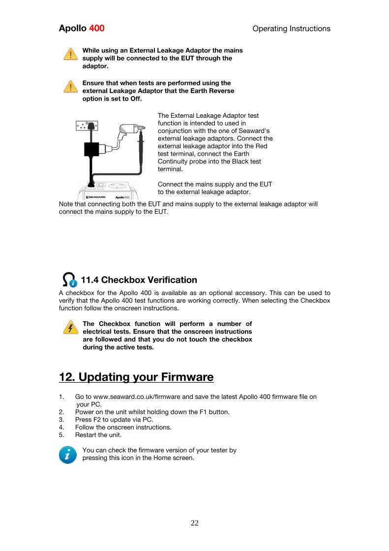
Apollo 400 Operating Instructions
22
While using an External Leakage Adaptor the mains
supply will be connected to the EUT through the
adaptor
Ensure that when tests are performed using the
external Leakage Adaptor that the Earth Reverse
option is set to Off
The External Leakage Adaptor test
function is intended to used in
conjunction with the one of Seawards
external leakage adaptors Connect the
external leakage adaptor into the Red
test terminal connect the Earth
Continuity probe into the Black test
terminal
Connect the mains supply and the EUT
to the external leakage adaptor
Note that connecting both the EUT and mains supply to the external leakage adaptor will
connect the mains supply to the EUT
114 Checkbox Verification
A checkbox for the Apollo 400 is available as an optional accessory This can be used to
verify that the Apollo 400 test functions are working correctly When selecting the Checkbox
function follow the onscreen instructions
The Checkbox function will perform a number of
electrical tests Ensure that the onscreen instructions
are followed and that you do not touch the checkbox
during the active tests
12 Updating your Firmware
1 Go to wwwseawardcoukfirmware and save the latest Apollo 400 firmware file on
your PC
2 Power on the unit whilst holding down the F1 button
3 Press F2 to update via PC
4 Follow the onscreen instructions
5 Restart the unit
You can check the firmware version of your tester by
pressing this icon in the Home screen
Apollo 400 Operating Instructions
23
13 Electrical Specification
Earth Continuity
Output Current (Load 2Ω)
Test Voltage (oc)
Measuring Range
Display Range
Resolution Operating Error
Number of tests as per IEC61557-
4
+- 200mA DC with ZAP
gt 4VDC
005 Ωndash 1999 Ω
001 Ω ndash 1999 Ω
001 Ω +-5 + 4 counts
approx 1500
Insulation Test
Test Voltages
Test Current
Test Voltage Accuracy
Measuring Range
Display Range
Resolution Operating Error ( lt 10MΩ ) ( gt 10MΩ )
Number of tests as per IEC61557-
2
500V and 250V DC
1mA minimum for a load of
1kohmvolt lt2mA into sc
+20 -0
010M Ω to 1999M Ω
000M Ω to 1999M Ω
001M Ω +-5 +5 counts +-10 +5 counts approx 1500
Subsitute Leakage Test
Test Voltages
Measuring Range
Display Range
Resolution Operating Error
gt25Vac lt50Vac
020mA to 1999mA
000mA to 1999mA
001mA +-10 +2 digits
Protective Conductor Current
Test Voltage
Display Range
Measurement Range
Resolution
Operating Error
Frequency Response
Supply Voltage maximum
load current 16A
001mA to 1999mA
025mA to 1999mA
001mA
+-5 of reading +- 3 digits
40Hz to 25 kHz
Touch Current
Test Voltage
Display Range
Measurement Range
Resolution
Operating Error
Frequency Response
Supply Voltage maximum
load current 16A
000mA to 350mA
010mA to 350mA
001mA
+-5 of reading +- 2 digits
DC to 25 kHz
Apollo 400 Operating Instructions
24
Load PowerCurrent
Test Voltage
Display Range
Measurement Range
Resolution
Operating Error
Supply Voltage maximum
load current 16A
000 - 1600A
050 - 1600A
001A
+-10 of reading +- 5 digits
Lead Test
Test Voltage
Test 5V DC nominal
Live Neutral checks for oc
sc and crossed
Power Socket Test
Input voltage range
195V ndash 253V AC
Indicates configuration of
voltage potential-
Line potential phase to earth
Line potential phase to neutral
Line potential neutral to earth
RCD Test
Test Voltage
Test Current
Test Current Accuracy
Display Range
Measuring Range
Resolution
Operating Error
230V +10 -15
30mA 150mA rms sinusoidal
30mA -10 +0 150mA +10 -0
0 ndash 2000ms
1ms ndash 2000ms
1ms plusmn1ms
External Leakage
Test Voltage
Display Range
Measuring Range
Resolution
Operating Error
Connected to External
Adapter
0mA - 999mA
025mA - 999mA
001mA +-5 of reading +-2 digits
Apollo 400 Operating Instructions
25
14 Useful Information - 141 Factory Set Test Sequences
Test
Visual Earth Continuity Insulation PE Conductor
Current Touch Current
Substitute
Leakage Wiring
RCD
Trip
Time
Name
Duration
(s)
Limit
(ΩΩ) Duration (s) Voltage
Limit
(MΩΩ)
Duration
(s)
Limit
(mA)
Duration
(s)
Limit
(mA)
Duration
(s)
Limit
(mA)
Limit
(ms)
PortableHandheldIT CLI Yes 5 01 2 500 1
PortableHandheldIT CLII Yes 2 500 2
Fixed Appliance CLI Yes 2 01 5 500 1
Fixed Appliance CLII Yes 5 500 2
IEC Lead 2m Yes 5 02 2 500 1 Yes
13A 5m Surge Protected Lead Yes 5 02 2 250 1 Yes
13A 25m Ext Lead 30mA RCD Yes 5 05 5 08 30
Portable CLI PE Current Yes 5 05 2 250 1 5 08
Portable CLII Touch Current Yes 2 250 2 5 03
IT Equip CLI PE Current Yes 5 01 2 250 1 5 35
IT Equip CLII T ouch Current Yes 2 250 5 03
13A 6m Mains Lead Yes 5 02 2 500 1 Yes
13A 12m Mains Lead Yes 5 03 2 500 1 Yes
13A 24m Mains Lead Yes 5 05 2 500 1 Yes
MovStat CLI 500V Insulation Yes 5 01 2 500 1
MovStat CLII 500V Insulation Yes 2 500 2
MovStat CLI PE Current Yes 5 01 2 250 1 5 35
MovStat CLII Touch Current Yes 2 250 2 5 35
110V HandheldPortable CLI Yes 5 01 2 500 1 2 08
110V HandheldPortable CLII Yes 2 500 2 2 03
110V MovableStationary CLI Yes 5 01 2 500 1 2 35
110V MovableStationary CLII Yes 2 500 2 2 03
110V 25m Lead
RpeampInsulation Yes 5 05 2 500 1
Visual Only Yes
Apollo 400 Operating Instructions
26
142 Other Information
Parameter Default Min Max
Earth Continuity PF limit (Ω) 01 001 1999
Earth Continuity Duration (s) 5 2 30
Insulation Resistance PF limit (MΩ) 1 001 1999
Insulation Resistance Duration (s) 5 2 30
Substitute Leakage PF limit (mA) 075 025 15
Substitute Leakage Duration (s) 5 2 30
IEC Cord Earth Continuity PF limit
(ohms) 01 001 5
IEC Cord Insulation PF limit (MΩ) 1 001 1999
Touch Current PF limit (mA) 025 025 350
Touch Current Duration (s) 5 2 30
PE Conductor Current PF limit (mA) 075 025 1999
PE Conductor Current Duration (s) 5 2 30
External Adapter Continuity (Ω) 01 001 5
External Adapter Leakage (mA) 075 025 999
External Adapter Duration (s) 5 2 30
RCD 30mA trip time (ms) 200 1 2000
RCD 150mA trip time (ms) 40 1 40
Number of tests in a test sequence 1 60
Characters in a test sequence name 1 30
Characters in a User Test name 1 15
Characters in a User Test Unit 15
Total number of Test Sequences 25
Test Results (typical) 2000
Sites 50
Characters in Site name 1 15
Locations 50
Characters in Location name 1 15
Users (including admin) 2
Characters in User name 1 15
Comments List 50
Characters in Comment 25
Characters in Asset ID 1 15
Apollo 400 Operating Instructions
27
15 Environmental Conditions
The Apollo 400 has been designed to perform tests and measurements in a dry environment
Maximum barometric elevation for making measurements is 2000M
Pollution degree 2 according to IEC 60529
Electromagnetic compatibility (EMC) Interference immunity and emitted interference
conforming to IEC 61326-1
Operating temperature range of 0 to 40 degrees C without moisture condensation
Operating Altitude 0 to 2000 metres
16 Maintenance
161 Charging the battery pack
The battery pack will be charged whenever the Apollo 400 is connected to the mains supply
regardless of whether it is switched on or off
The typical charging current is set to 500mA but this may vary as the instrument also
includes pre-charge and top up charge modes
When no tests are being performed the battery pack will be fully re-charged after 7 hours
162 Securing the Apollo 400
Under certain conditions safe operation of the Apollo 400 can no longer be assumed
Visible damage of the instrument case
Incorrect measurement results
Recognisable abuse to the instrument due to prolonged storage under improper conditions
Recognisable abuse to the instrument due to extraordinary transportation stress
In these case the Apollo 400 should be immediately switched off disconnected from any test
and measurement function and secured to prevent any further use
163 Cleaning the Apollo 400
Clean the external case of the Apollo 400 with a dry clean cloth
Avoid using solvents and abrasive scouring agents to clean the external case of the Apollo
400
Apollo 400 Operating Instructions
28
164 Replacing the battery pack
Before opening the Apollo 400 battery compartment
ensure that all test leads and accessories are
disconnected
Power off the instrument
Disconnect all test leads and accessories
Position the instrument face down and remove the screw holding the battery compartment
cover in place
Remove the battery compartment cover
Remove the battery pack from the compartment and unplug the 4 way connector
Connect the 4 way connector of the new battery to the 4 way header in the battery
compartment put the battery pack into the compartment
Relocate the battery compartment cover and fasten in position with the battery compartment
screw
ONLY USE A REPLACEMENT BATTERY PACK THAT HAS BEEN SUPPLIED BY SEAWARD
OR A SEAWARD APPROVED DISTRIBUTOR
17 Support
The Apollo 400 must be registered with Seaward before support will be made available For Technical Support contact Tel (+44) 191 587 8718
For help or advice on Service and Calibration contact
CalibrationHouse Seaward Electronic Bracken Hill South West Industrial Estate Peterlee Co Durham SR8 2SW England Tel (+44) 191 5878739 (+44) 191 5878737 Email serviceseawardcouk
Calibration House is part of the Seaward Group
Apollo 400 Operating Instructions
29
171 Register your product here-
wwwseawardcouk 172 Calibration Services-
wwwcalibrationhousecouk Bracken Hill South West Industrial Estate Peterlee County Durham SR8 2SW Co Durham SR8 2SW England Tel (+44) 191 5863511 Some icons provided by Fat Cow (httpwwwfatcowcomfree-icons) Based in part on the work of the Qwt project (httpqwtsfnet)
Apollo 400A simple no-nonsense PAT tester with fast data entry and storage for up to 2000appliance records
Key Featuresn High definition colour displayn Store 2000 appliance recordsn Remote data transfer from field to office n Bluetooth connectivity
Electrical Test Functionsn Low current earth continuity test guaranteeing accurate measurement n Point to point testing (earth continuity and insulation resistance)n Insulation resistancen IEC lead testn Protective conductor currentn Touch currentn Load powercurrentn Alternative leakage currentn RCD testn Power socket test
Ideal Forn Electrical Contractorsn Facilities Managersn Operations Managers
Apollo 400 offers simple electrical safety testing with straightforward data entryusing the intuitive QWERTY keypad
A comprehensive range of electrical safety tests ensure compliance with theIET 4th Edition Code of Practice whilst remote data transfer and USB downloadmakes data management easy and efficient
The Apollo 400 is ideal for mid-volume PAT testing where detailed records arerequired
Streamline the PAT testing process further by using the Apollo 400 with acompatible label printer barcode scanner and PATGuard 3 software
wwwseawardcoukapollo400
Tel +44 (0) 191 587 8741Email salesseawardcouk
Requires optional accessory (part number 380A983)
Straightforward PAT testing with simple data managementApollo 400 offers a comprehensive suite of electrical safetytests to enable any workplace appliance to be tested including3-phase equipment fixed appliances and RCDs
The QWERTY keypad enables asset information to be entered quicklyand easily while a large colour display with an intuitive menu structure makesthe Apollo 400 simple to grasp Lightweight and small in size with battery or mainspower modes the Apollo 400 is good to go in seconds allowing more appliances to betested without downtime for boot-up or a battery re-charge
Superb software for total traceabilityApollo 400 has an internal memory capable of storing up to 2000electrical test records Its compatibility with Seawardrsquos PATGuard 3software means that complete test records are easily managed ona PC
Transfer data to the PC remotely using the Bluetooth function anda smartphone or download the results via a USB cable directly toa PC Once downloaded to PATGuard 3 it is easy to keep track ofthe history of test and inspections as well as produce reportscertificates and invoices ndash offering total peace of mind and quickereasier management of scheduling inspections and tests
Download a free trial at wwwseawardcoukpg3trial
wwwseawardcoukapollo400
Tel +44 (0) 191 587 8741Email salesseawardcouk
additional accessory required for point to point testing
u Accessory BundlesThe Apollo 400 is available to buy with a selectionof optional accessory bundles to help you get themost out of your tester
Apollo 400 is supplied as standard with a UKAScalibration certificate and a 2 yearmanufacturerrsquos warranty (subject to terms andconditions)
Greater efficiency through useful accessoriesAs with many Seaward PAT testers the Apollo 400 is compatible with arange of printers and barcode scanners further speeding up the processof asset recognition testing and labelling
Also available in this range
A multi-tasking and fully customisable PAT with additionalhealth and safety features and on-board camera forunrivalled record keeping
Apollo 600 includes a universal risk assessment tool andthe ability to store up to 50000 appliance records plus2000 images - providing visual evidence of testenvironments perfect for advanced record-keeping inorganisations with high-volume workplace test andinspection routines
Apollo 600Multi-tasking PAT tester with on-board camera
wwwseawardcoukapollo400
Tel +44 (0) 191 587 8741Email salesseawardcouk
A powerful PAT tester with a built-in PAT retest calculatorand flexible user-configurable sequences for recordingany non-electrical workplace test or inspection
The ability to customise a number of settings and a largememory to store up to 10000 appliance records makesthe Apollo 500 a versatile and dependable tool for highvolume PAT testing
Apollo 500A fast amp fully customisable and versatile PAT tester
Optional accessory bundles available Part Number
Elite Bundle n Test n Tag Elite 2 rugged portable printer
n Test n Tag printer labels x 4
n Bluetooth barcode scanner
n Apollo kit carry case
n 110V adapter
Includes Apollo 400 tester
380A978
Elite Bundle +Software
PLUS PATGuard 3 software 1yr licence 380A979
Pro Bundle n Test n Tag Pro lightweight portable printer
n Test n Tag printer labels x 4
n Bluetooth barcode scanner
n Apollo kit carry case
n 110V adapter
Includes Apollo 400 tester
380A980
Pro Bundle +Software PLUS PATGuard 3 software 1yr licence 380A981
wwwseawardcoukapollo400
Tel +44 (0) 191 587 8741Email salesseawardcouk
Apollo 400 Apollo 500 Apollo 600
General Features
Battery amp mains powered n n n
Colour Screen amp QWERTY keypad n n n
Large internal memory 2000 records 10000 records 50000 records
Scanner amp printer compatible n n n
Password controlled user accounts n n
Set up multiple user accounts with varyinglevels of privileges
n n
Clone facility to set up multiple testers n n
Checkbox supplied as standard n n
On-board user manual n n
Test amp InspectionFeatures
Auto-increment asset ID n n
PAT Setup option to allow for custom menus n n
Enter asset description after test usingkeypad or barcode scanner
n n n
Comprehensive electrical safety test features n n n
Point to point measurement (Rpe amp IR)
n
(optional
accessory
required)
n n
User configurable electrical testvisualinspection sequences 25 100 100
User set sites amp locations 50 100 100
Risk based retest period calculator n n
User definable comments lines against testrecords
n n
Configurable checklists for any workplacetest or inspection (user tests)
n n
On-board camera n
Universal risk assessment n
Health amp safety certificates n
Data Transfer
Bluetooth connectivity n n n
Barcode scanner connectivity n n n
Print Pass amp Fail labels n n n
Add your company logo to labels n n
Select from various label formats to print n n
Remote data transfer via mobile device n
(Android only)
n
(Android only)
n
(Android and iOS)
Download to PC via USB cable n n n
Filter results to be downloaded n n
Upload previous results to tester for retest n n
Data transfer via USB flash drive n
Apollo Series Comparison Chart
PAT TESTS
Earth ContinuityTest Current +- 200mA DC Display Range 001 ndash 1999ΩPass Value User Defined
Insulation ResistanceTest Voltage 500V 250VDC 1mA nominalDisplay Range 001MΩ - 1999MΩPass Value User Defined
IEC Lead TestTest Voltage 5VAC nominalTest Live Neutral Checks for oc sc and crossed
Protective Conductor CurrentLoad
Test Voltage Supply voltage maximum load current 16A Display Ranges 001mA to 1999mA Pass Value User Defined
Touch Current
Test Voltage Supply Voltage maximum load current 16ADisplay Range 000 ndash 350mA Pass Value User defined
Load PowerCurrent
Test Voltage Supply Voltage maximum load current 16ATest Duration Programmable up to a maximum of 255s depending on load ie max duration is reduced for high loadsDisplay Range 000kVA ndash 400kVA 000A ndash 1600A
Alternative Leakage Current
Test Voltages gt25VAC lt50VAC Display Range 000mA to 1999mAPass Value User Defined
RCD Test
Test Voltage 230V +10 -15Test Current 30mA 150mA rms sinusoidalDisplay Range 0ms - 2000ms (30mA) 0-40ms (150mA)Test Method Internal isolation to avoid tripping distribution board RCD
Power Socket Test
Voltage Range 207V ndash 253VACIndicates configuration of voltage potential-Line potential phase to earthLine potential phase to neutralLine potential neutral to earth
General
Memory Size 2000 recordsWeight 15kgDimensions 230mm x 150mm x 100mmPower Source Mains or rechargeable battery pack
Standard Accessories (supplied with Apollo 400)30 day free trial of PATGuard 3 software 1x red test lead and probe with crocodile clip05m IEC leadMains power leadUSB download cableQuick start guideUKAS calibration certificate
Optional Accessories Test n Tag Elite 2 Bluetooth printer with roll of small labels (339A995)Test n Tag Pro Bluetooth printer with roll of small labels (339A987)Roll of small labels (approx 350 off 52 x 25mm labels) (339A947)Additional black test lead and probe with crocodile clip (for point to point testing) (380A983)Bluetooth barcode scanner (339A923)110V test adaptor (270A076)110V to IEC adapter (344A050)Apollo checkbox (380A953)3 Phase Leakage Adaptor 5 Star 16A (391A920)3 Phase Leakage Adaptor 5 Star 32A (391A910)3 Phase Adapter Delta 4 pin 16A 415V (for Rpe amp IR) (209A910)3 Phase Adapter Star 5 pin 16A 415V (for Rpe amp IR) (209A911)3 Phase Adapter Delta 4 pin 32A 415V (for Rpe amp IR) (209A912)3 Phase Adapter Star 5 pin 32A 415V (for Rpe amp IR) (209A913)Professional Seaward kit bag (71G109)Apollo carry case (380A952)PATGuard 3 software ndash download 30 day free trial atwwwseawardcoukpg3trial
Part NumbersApollo 400 standard package 380A920Apollo 400 with Elite accessory bundle 380A978Apollo 400 with Elite accessory bundle amp PATGuard 3 one year licence380A979Apollo 400 with Pro accessory bundle 380A980Apollo 400 with Pro accessory bundle amp PATGuard 3 one year licence380A981
TrainingSeaward offer a range of PAT testing courses including City amp GuildsGo to wwwseawardcouktraining for more information
Services2 year warranty (subject to terms and conditions available atwwwseawardcoukwarranty24)Service amp Calibration by CalibrationhouseGo to wwwcalibrationhousecom for more information
Technical Specifications
Part of
Rev 12
wwwseawardcoukapollo400
Tel +44 (0) 191 587 8741Email salesseawardcouk
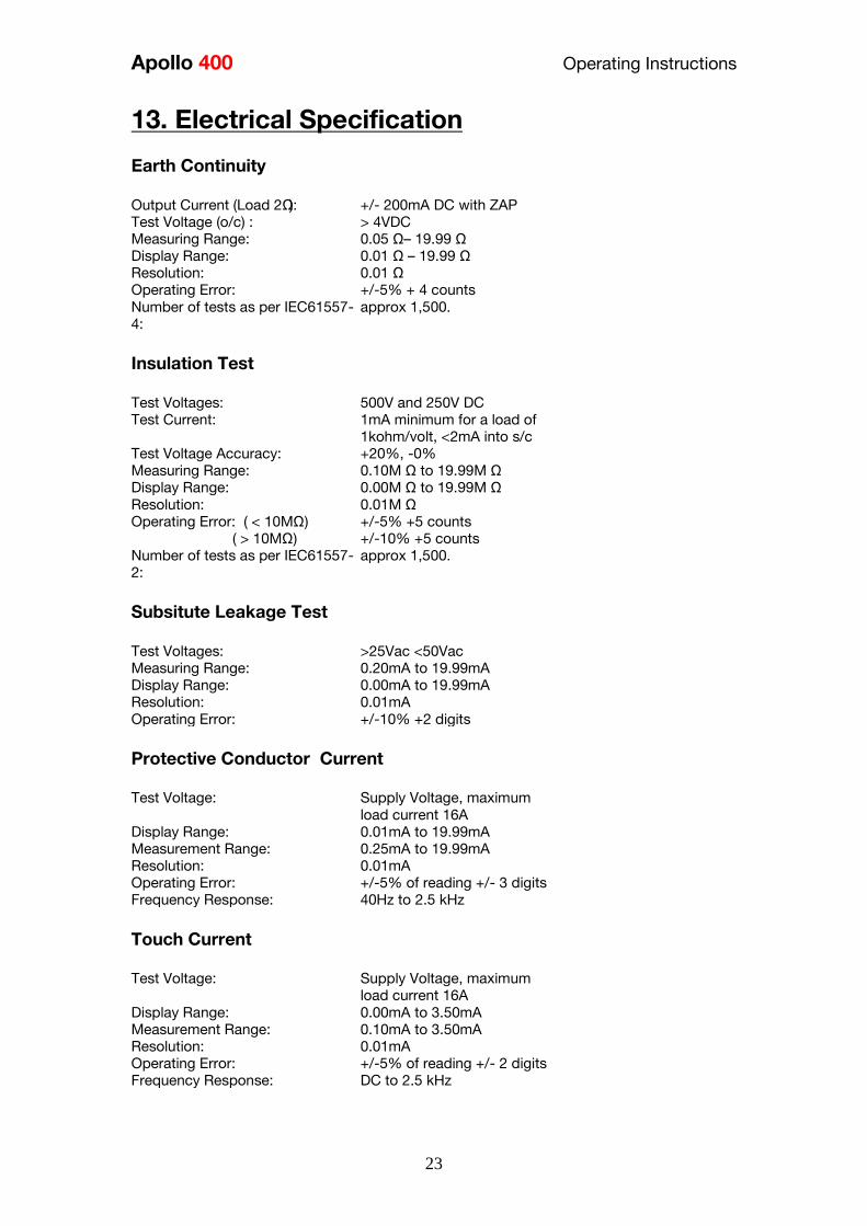
Apollo 400 Operating Instructions
23
13 Electrical Specification
Earth Continuity
Output Current (Load 2Ω)
Test Voltage (oc)
Measuring Range
Display Range
Resolution Operating Error
Number of tests as per IEC61557-
4
+- 200mA DC with ZAP
gt 4VDC
005 Ωndash 1999 Ω
001 Ω ndash 1999 Ω
001 Ω +-5 + 4 counts
approx 1500
Insulation Test
Test Voltages
Test Current
Test Voltage Accuracy
Measuring Range
Display Range
Resolution Operating Error ( lt 10MΩ ) ( gt 10MΩ )
Number of tests as per IEC61557-
2
500V and 250V DC
1mA minimum for a load of
1kohmvolt lt2mA into sc
+20 -0
010M Ω to 1999M Ω
000M Ω to 1999M Ω
001M Ω +-5 +5 counts +-10 +5 counts approx 1500
Subsitute Leakage Test
Test Voltages
Measuring Range
Display Range
Resolution Operating Error
gt25Vac lt50Vac
020mA to 1999mA
000mA to 1999mA
001mA +-10 +2 digits
Protective Conductor Current
Test Voltage
Display Range
Measurement Range
Resolution
Operating Error
Frequency Response
Supply Voltage maximum
load current 16A
001mA to 1999mA
025mA to 1999mA
001mA
+-5 of reading +- 3 digits
40Hz to 25 kHz
Touch Current
Test Voltage
Display Range
Measurement Range
Resolution
Operating Error
Frequency Response
Supply Voltage maximum
load current 16A
000mA to 350mA
010mA to 350mA
001mA
+-5 of reading +- 2 digits
DC to 25 kHz
Apollo 400 Operating Instructions
24
Load PowerCurrent
Test Voltage
Display Range
Measurement Range
Resolution
Operating Error
Supply Voltage maximum
load current 16A
000 - 1600A
050 - 1600A
001A
+-10 of reading +- 5 digits
Lead Test
Test Voltage
Test 5V DC nominal
Live Neutral checks for oc
sc and crossed
Power Socket Test
Input voltage range
195V ndash 253V AC
Indicates configuration of
voltage potential-
Line potential phase to earth
Line potential phase to neutral
Line potential neutral to earth
RCD Test
Test Voltage
Test Current
Test Current Accuracy
Display Range
Measuring Range
Resolution
Operating Error
230V +10 -15
30mA 150mA rms sinusoidal
30mA -10 +0 150mA +10 -0
0 ndash 2000ms
1ms ndash 2000ms
1ms plusmn1ms
External Leakage
Test Voltage
Display Range
Measuring Range
Resolution
Operating Error
Connected to External
Adapter
0mA - 999mA
025mA - 999mA
001mA +-5 of reading +-2 digits
Apollo 400 Operating Instructions
25
14 Useful Information - 141 Factory Set Test Sequences
Test
Visual Earth Continuity Insulation PE Conductor
Current Touch Current
Substitute
Leakage Wiring
RCD
Trip
Time
Name
Duration
(s)
Limit
(ΩΩ) Duration (s) Voltage
Limit
(MΩΩ)
Duration
(s)
Limit
(mA)
Duration
(s)
Limit
(mA)
Duration
(s)
Limit
(mA)
Limit
(ms)
PortableHandheldIT CLI Yes 5 01 2 500 1
PortableHandheldIT CLII Yes 2 500 2
Fixed Appliance CLI Yes 2 01 5 500 1
Fixed Appliance CLII Yes 5 500 2
IEC Lead 2m Yes 5 02 2 500 1 Yes
13A 5m Surge Protected Lead Yes 5 02 2 250 1 Yes
13A 25m Ext Lead 30mA RCD Yes 5 05 5 08 30
Portable CLI PE Current Yes 5 05 2 250 1 5 08
Portable CLII Touch Current Yes 2 250 2 5 03
IT Equip CLI PE Current Yes 5 01 2 250 1 5 35
IT Equip CLII T ouch Current Yes 2 250 5 03
13A 6m Mains Lead Yes 5 02 2 500 1 Yes
13A 12m Mains Lead Yes 5 03 2 500 1 Yes
13A 24m Mains Lead Yes 5 05 2 500 1 Yes
MovStat CLI 500V Insulation Yes 5 01 2 500 1
MovStat CLII 500V Insulation Yes 2 500 2
MovStat CLI PE Current Yes 5 01 2 250 1 5 35
MovStat CLII Touch Current Yes 2 250 2 5 35
110V HandheldPortable CLI Yes 5 01 2 500 1 2 08
110V HandheldPortable CLII Yes 2 500 2 2 03
110V MovableStationary CLI Yes 5 01 2 500 1 2 35
110V MovableStationary CLII Yes 2 500 2 2 03
110V 25m Lead
RpeampInsulation Yes 5 05 2 500 1
Visual Only Yes
Apollo 400 Operating Instructions
26
142 Other Information
Parameter Default Min Max
Earth Continuity PF limit (Ω) 01 001 1999
Earth Continuity Duration (s) 5 2 30
Insulation Resistance PF limit (MΩ) 1 001 1999
Insulation Resistance Duration (s) 5 2 30
Substitute Leakage PF limit (mA) 075 025 15
Substitute Leakage Duration (s) 5 2 30
IEC Cord Earth Continuity PF limit
(ohms) 01 001 5
IEC Cord Insulation PF limit (MΩ) 1 001 1999
Touch Current PF limit (mA) 025 025 350
Touch Current Duration (s) 5 2 30
PE Conductor Current PF limit (mA) 075 025 1999
PE Conductor Current Duration (s) 5 2 30
External Adapter Continuity (Ω) 01 001 5
External Adapter Leakage (mA) 075 025 999
External Adapter Duration (s) 5 2 30
RCD 30mA trip time (ms) 200 1 2000
RCD 150mA trip time (ms) 40 1 40
Number of tests in a test sequence 1 60
Characters in a test sequence name 1 30
Characters in a User Test name 1 15
Characters in a User Test Unit 15
Total number of Test Sequences 25
Test Results (typical) 2000
Sites 50
Characters in Site name 1 15
Locations 50
Characters in Location name 1 15
Users (including admin) 2
Characters in User name 1 15
Comments List 50
Characters in Comment 25
Characters in Asset ID 1 15
Apollo 400 Operating Instructions
27
15 Environmental Conditions
The Apollo 400 has been designed to perform tests and measurements in a dry environment
Maximum barometric elevation for making measurements is 2000M
Pollution degree 2 according to IEC 60529
Electromagnetic compatibility (EMC) Interference immunity and emitted interference
conforming to IEC 61326-1
Operating temperature range of 0 to 40 degrees C without moisture condensation
Operating Altitude 0 to 2000 metres
16 Maintenance
161 Charging the battery pack
The battery pack will be charged whenever the Apollo 400 is connected to the mains supply
regardless of whether it is switched on or off
The typical charging current is set to 500mA but this may vary as the instrument also
includes pre-charge and top up charge modes
When no tests are being performed the battery pack will be fully re-charged after 7 hours
162 Securing the Apollo 400
Under certain conditions safe operation of the Apollo 400 can no longer be assumed
Visible damage of the instrument case
Incorrect measurement results
Recognisable abuse to the instrument due to prolonged storage under improper conditions
Recognisable abuse to the instrument due to extraordinary transportation stress
In these case the Apollo 400 should be immediately switched off disconnected from any test
and measurement function and secured to prevent any further use
163 Cleaning the Apollo 400
Clean the external case of the Apollo 400 with a dry clean cloth
Avoid using solvents and abrasive scouring agents to clean the external case of the Apollo
400
Apollo 400 Operating Instructions
28
164 Replacing the battery pack
Before opening the Apollo 400 battery compartment
ensure that all test leads and accessories are
disconnected
Power off the instrument
Disconnect all test leads and accessories
Position the instrument face down and remove the screw holding the battery compartment
cover in place
Remove the battery compartment cover
Remove the battery pack from the compartment and unplug the 4 way connector
Connect the 4 way connector of the new battery to the 4 way header in the battery
compartment put the battery pack into the compartment
Relocate the battery compartment cover and fasten in position with the battery compartment
screw
ONLY USE A REPLACEMENT BATTERY PACK THAT HAS BEEN SUPPLIED BY SEAWARD
OR A SEAWARD APPROVED DISTRIBUTOR
17 Support
The Apollo 400 must be registered with Seaward before support will be made available For Technical Support contact Tel (+44) 191 587 8718
For help or advice on Service and Calibration contact
CalibrationHouse Seaward Electronic Bracken Hill South West Industrial Estate Peterlee Co Durham SR8 2SW England Tel (+44) 191 5878739 (+44) 191 5878737 Email serviceseawardcouk
Calibration House is part of the Seaward Group
Apollo 400 Operating Instructions
29
171 Register your product here-
wwwseawardcouk 172 Calibration Services-
wwwcalibrationhousecouk Bracken Hill South West Industrial Estate Peterlee County Durham SR8 2SW Co Durham SR8 2SW England Tel (+44) 191 5863511 Some icons provided by Fat Cow (httpwwwfatcowcomfree-icons) Based in part on the work of the Qwt project (httpqwtsfnet)
Apollo 400A simple no-nonsense PAT tester with fast data entry and storage for up to 2000appliance records
Key Featuresn High definition colour displayn Store 2000 appliance recordsn Remote data transfer from field to office n Bluetooth connectivity
Electrical Test Functionsn Low current earth continuity test guaranteeing accurate measurement n Point to point testing (earth continuity and insulation resistance)n Insulation resistancen IEC lead testn Protective conductor currentn Touch currentn Load powercurrentn Alternative leakage currentn RCD testn Power socket test
Ideal Forn Electrical Contractorsn Facilities Managersn Operations Managers
Apollo 400 offers simple electrical safety testing with straightforward data entryusing the intuitive QWERTY keypad
A comprehensive range of electrical safety tests ensure compliance with theIET 4th Edition Code of Practice whilst remote data transfer and USB downloadmakes data management easy and efficient
The Apollo 400 is ideal for mid-volume PAT testing where detailed records arerequired
Streamline the PAT testing process further by using the Apollo 400 with acompatible label printer barcode scanner and PATGuard 3 software
wwwseawardcoukapollo400
Tel +44 (0) 191 587 8741Email salesseawardcouk
Requires optional accessory (part number 380A983)
Straightforward PAT testing with simple data managementApollo 400 offers a comprehensive suite of electrical safetytests to enable any workplace appliance to be tested including3-phase equipment fixed appliances and RCDs
The QWERTY keypad enables asset information to be entered quicklyand easily while a large colour display with an intuitive menu structure makesthe Apollo 400 simple to grasp Lightweight and small in size with battery or mainspower modes the Apollo 400 is good to go in seconds allowing more appliances to betested without downtime for boot-up or a battery re-charge
Superb software for total traceabilityApollo 400 has an internal memory capable of storing up to 2000electrical test records Its compatibility with Seawardrsquos PATGuard 3software means that complete test records are easily managed ona PC
Transfer data to the PC remotely using the Bluetooth function anda smartphone or download the results via a USB cable directly toa PC Once downloaded to PATGuard 3 it is easy to keep track ofthe history of test and inspections as well as produce reportscertificates and invoices ndash offering total peace of mind and quickereasier management of scheduling inspections and tests
Download a free trial at wwwseawardcoukpg3trial
wwwseawardcoukapollo400
Tel +44 (0) 191 587 8741Email salesseawardcouk
additional accessory required for point to point testing
u Accessory BundlesThe Apollo 400 is available to buy with a selectionof optional accessory bundles to help you get themost out of your tester
Apollo 400 is supplied as standard with a UKAScalibration certificate and a 2 yearmanufacturerrsquos warranty (subject to terms andconditions)
Greater efficiency through useful accessoriesAs with many Seaward PAT testers the Apollo 400 is compatible with arange of printers and barcode scanners further speeding up the processof asset recognition testing and labelling
Also available in this range
A multi-tasking and fully customisable PAT with additionalhealth and safety features and on-board camera forunrivalled record keeping
Apollo 600 includes a universal risk assessment tool andthe ability to store up to 50000 appliance records plus2000 images - providing visual evidence of testenvironments perfect for advanced record-keeping inorganisations with high-volume workplace test andinspection routines
Apollo 600Multi-tasking PAT tester with on-board camera
wwwseawardcoukapollo400
Tel +44 (0) 191 587 8741Email salesseawardcouk
A powerful PAT tester with a built-in PAT retest calculatorand flexible user-configurable sequences for recordingany non-electrical workplace test or inspection
The ability to customise a number of settings and a largememory to store up to 10000 appliance records makesthe Apollo 500 a versatile and dependable tool for highvolume PAT testing
Apollo 500A fast amp fully customisable and versatile PAT tester
Optional accessory bundles available Part Number
Elite Bundle n Test n Tag Elite 2 rugged portable printer
n Test n Tag printer labels x 4
n Bluetooth barcode scanner
n Apollo kit carry case
n 110V adapter
Includes Apollo 400 tester
380A978
Elite Bundle +Software
PLUS PATGuard 3 software 1yr licence 380A979
Pro Bundle n Test n Tag Pro lightweight portable printer
n Test n Tag printer labels x 4
n Bluetooth barcode scanner
n Apollo kit carry case
n 110V adapter
Includes Apollo 400 tester
380A980
Pro Bundle +Software PLUS PATGuard 3 software 1yr licence 380A981
wwwseawardcoukapollo400
Tel +44 (0) 191 587 8741Email salesseawardcouk
Apollo 400 Apollo 500 Apollo 600
General Features
Battery amp mains powered n n n
Colour Screen amp QWERTY keypad n n n
Large internal memory 2000 records 10000 records 50000 records
Scanner amp printer compatible n n n
Password controlled user accounts n n
Set up multiple user accounts with varyinglevels of privileges
n n
Clone facility to set up multiple testers n n
Checkbox supplied as standard n n
On-board user manual n n
Test amp InspectionFeatures
Auto-increment asset ID n n
PAT Setup option to allow for custom menus n n
Enter asset description after test usingkeypad or barcode scanner
n n n
Comprehensive electrical safety test features n n n
Point to point measurement (Rpe amp IR)
n
(optional
accessory
required)
n n
User configurable electrical testvisualinspection sequences 25 100 100
User set sites amp locations 50 100 100
Risk based retest period calculator n n
User definable comments lines against testrecords
n n
Configurable checklists for any workplacetest or inspection (user tests)
n n
On-board camera n
Universal risk assessment n
Health amp safety certificates n
Data Transfer
Bluetooth connectivity n n n
Barcode scanner connectivity n n n
Print Pass amp Fail labels n n n
Add your company logo to labels n n
Select from various label formats to print n n
Remote data transfer via mobile device n
(Android only)
n
(Android only)
n
(Android and iOS)
Download to PC via USB cable n n n
Filter results to be downloaded n n
Upload previous results to tester for retest n n
Data transfer via USB flash drive n
Apollo Series Comparison Chart
PAT TESTS
Earth ContinuityTest Current +- 200mA DC Display Range 001 ndash 1999ΩPass Value User Defined
Insulation ResistanceTest Voltage 500V 250VDC 1mA nominalDisplay Range 001MΩ - 1999MΩPass Value User Defined
IEC Lead TestTest Voltage 5VAC nominalTest Live Neutral Checks for oc sc and crossed
Protective Conductor CurrentLoad
Test Voltage Supply voltage maximum load current 16A Display Ranges 001mA to 1999mA Pass Value User Defined
Touch Current
Test Voltage Supply Voltage maximum load current 16ADisplay Range 000 ndash 350mA Pass Value User defined
Load PowerCurrent
Test Voltage Supply Voltage maximum load current 16ATest Duration Programmable up to a maximum of 255s depending on load ie max duration is reduced for high loadsDisplay Range 000kVA ndash 400kVA 000A ndash 1600A
Alternative Leakage Current
Test Voltages gt25VAC lt50VAC Display Range 000mA to 1999mAPass Value User Defined
RCD Test
Test Voltage 230V +10 -15Test Current 30mA 150mA rms sinusoidalDisplay Range 0ms - 2000ms (30mA) 0-40ms (150mA)Test Method Internal isolation to avoid tripping distribution board RCD
Power Socket Test
Voltage Range 207V ndash 253VACIndicates configuration of voltage potential-Line potential phase to earthLine potential phase to neutralLine potential neutral to earth
General
Memory Size 2000 recordsWeight 15kgDimensions 230mm x 150mm x 100mmPower Source Mains or rechargeable battery pack
Standard Accessories (supplied with Apollo 400)30 day free trial of PATGuard 3 software 1x red test lead and probe with crocodile clip05m IEC leadMains power leadUSB download cableQuick start guideUKAS calibration certificate
Optional Accessories Test n Tag Elite 2 Bluetooth printer with roll of small labels (339A995)Test n Tag Pro Bluetooth printer with roll of small labels (339A987)Roll of small labels (approx 350 off 52 x 25mm labels) (339A947)Additional black test lead and probe with crocodile clip (for point to point testing) (380A983)Bluetooth barcode scanner (339A923)110V test adaptor (270A076)110V to IEC adapter (344A050)Apollo checkbox (380A953)3 Phase Leakage Adaptor 5 Star 16A (391A920)3 Phase Leakage Adaptor 5 Star 32A (391A910)3 Phase Adapter Delta 4 pin 16A 415V (for Rpe amp IR) (209A910)3 Phase Adapter Star 5 pin 16A 415V (for Rpe amp IR) (209A911)3 Phase Adapter Delta 4 pin 32A 415V (for Rpe amp IR) (209A912)3 Phase Adapter Star 5 pin 32A 415V (for Rpe amp IR) (209A913)Professional Seaward kit bag (71G109)Apollo carry case (380A952)PATGuard 3 software ndash download 30 day free trial atwwwseawardcoukpg3trial
Part NumbersApollo 400 standard package 380A920Apollo 400 with Elite accessory bundle 380A978Apollo 400 with Elite accessory bundle amp PATGuard 3 one year licence380A979Apollo 400 with Pro accessory bundle 380A980Apollo 400 with Pro accessory bundle amp PATGuard 3 one year licence380A981
TrainingSeaward offer a range of PAT testing courses including City amp GuildsGo to wwwseawardcouktraining for more information
Services2 year warranty (subject to terms and conditions available atwwwseawardcoukwarranty24)Service amp Calibration by CalibrationhouseGo to wwwcalibrationhousecom for more information
Technical Specifications
Part of
Rev 12
wwwseawardcoukapollo400
Tel +44 (0) 191 587 8741Email salesseawardcouk
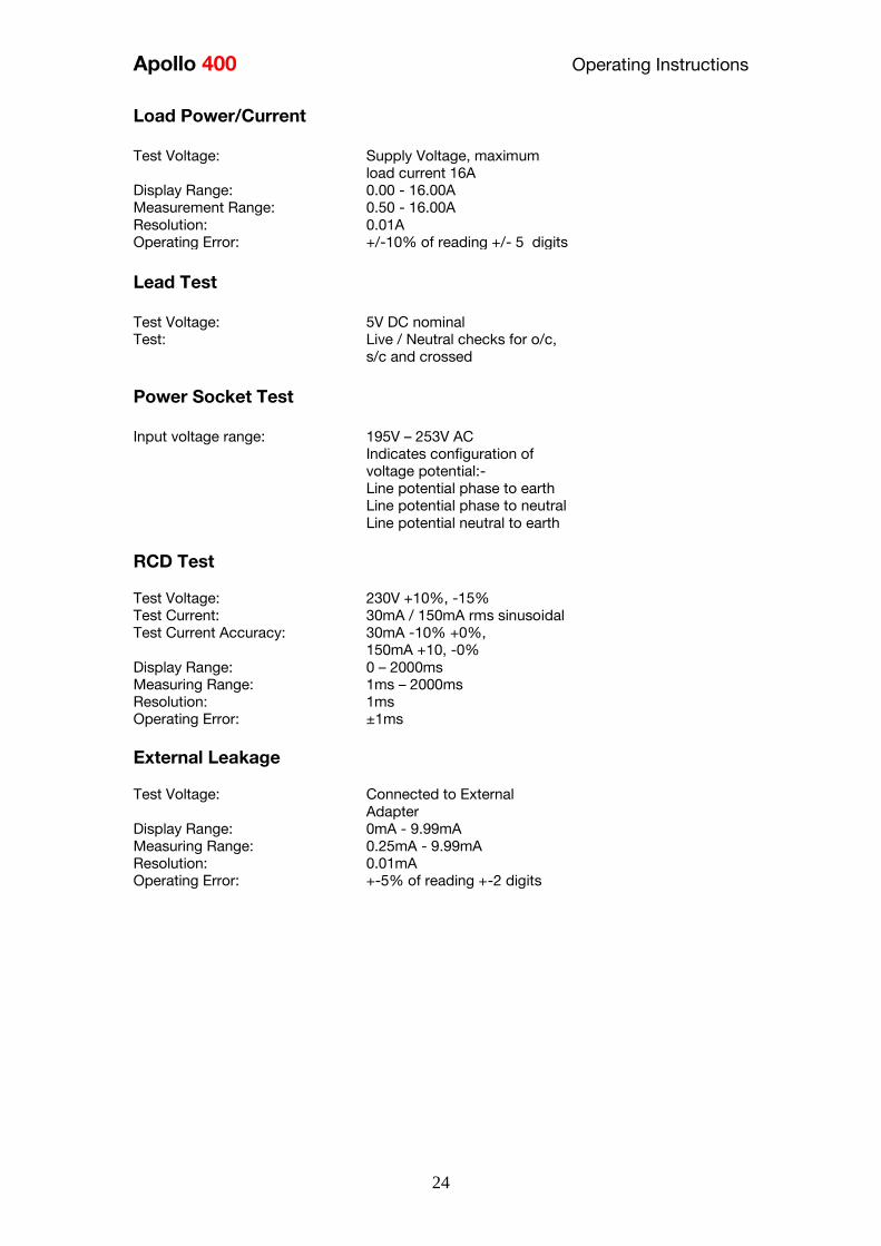
Apollo 400 Operating Instructions
24
Load PowerCurrent
Test Voltage
Display Range
Measurement Range
Resolution
Operating Error
Supply Voltage maximum
load current 16A
000 - 1600A
050 - 1600A
001A
+-10 of reading +- 5 digits
Lead Test
Test Voltage
Test 5V DC nominal
Live Neutral checks for oc
sc and crossed
Power Socket Test
Input voltage range
195V ndash 253V AC
Indicates configuration of
voltage potential-
Line potential phase to earth
Line potential phase to neutral
Line potential neutral to earth
RCD Test
Test Voltage
Test Current
Test Current Accuracy
Display Range
Measuring Range
Resolution
Operating Error
230V +10 -15
30mA 150mA rms sinusoidal
30mA -10 +0 150mA +10 -0
0 ndash 2000ms
1ms ndash 2000ms
1ms plusmn1ms
External Leakage
Test Voltage
Display Range
Measuring Range
Resolution
Operating Error
Connected to External
Adapter
0mA - 999mA
025mA - 999mA
001mA +-5 of reading +-2 digits
Apollo 400 Operating Instructions
25
14 Useful Information - 141 Factory Set Test Sequences
Test
Visual Earth Continuity Insulation PE Conductor
Current Touch Current
Substitute
Leakage Wiring
RCD
Trip
Time
Name
Duration
(s)
Limit
(ΩΩ) Duration (s) Voltage
Limit
(MΩΩ)
Duration
(s)
Limit
(mA)
Duration
(s)
Limit
(mA)
Duration
(s)
Limit
(mA)
Limit
(ms)
PortableHandheldIT CLI Yes 5 01 2 500 1
PortableHandheldIT CLII Yes 2 500 2
Fixed Appliance CLI Yes 2 01 5 500 1
Fixed Appliance CLII Yes 5 500 2
IEC Lead 2m Yes 5 02 2 500 1 Yes
13A 5m Surge Protected Lead Yes 5 02 2 250 1 Yes
13A 25m Ext Lead 30mA RCD Yes 5 05 5 08 30
Portable CLI PE Current Yes 5 05 2 250 1 5 08
Portable CLII Touch Current Yes 2 250 2 5 03
IT Equip CLI PE Current Yes 5 01 2 250 1 5 35
IT Equip CLII T ouch Current Yes 2 250 5 03
13A 6m Mains Lead Yes 5 02 2 500 1 Yes
13A 12m Mains Lead Yes 5 03 2 500 1 Yes
13A 24m Mains Lead Yes 5 05 2 500 1 Yes
MovStat CLI 500V Insulation Yes 5 01 2 500 1
MovStat CLII 500V Insulation Yes 2 500 2
MovStat CLI PE Current Yes 5 01 2 250 1 5 35
MovStat CLII Touch Current Yes 2 250 2 5 35
110V HandheldPortable CLI Yes 5 01 2 500 1 2 08
110V HandheldPortable CLII Yes 2 500 2 2 03
110V MovableStationary CLI Yes 5 01 2 500 1 2 35
110V MovableStationary CLII Yes 2 500 2 2 03
110V 25m Lead
RpeampInsulation Yes 5 05 2 500 1
Visual Only Yes
Apollo 400 Operating Instructions
26
142 Other Information
Parameter Default Min Max
Earth Continuity PF limit (Ω) 01 001 1999
Earth Continuity Duration (s) 5 2 30
Insulation Resistance PF limit (MΩ) 1 001 1999
Insulation Resistance Duration (s) 5 2 30
Substitute Leakage PF limit (mA) 075 025 15
Substitute Leakage Duration (s) 5 2 30
IEC Cord Earth Continuity PF limit
(ohms) 01 001 5
IEC Cord Insulation PF limit (MΩ) 1 001 1999
Touch Current PF limit (mA) 025 025 350
Touch Current Duration (s) 5 2 30
PE Conductor Current PF limit (mA) 075 025 1999
PE Conductor Current Duration (s) 5 2 30
External Adapter Continuity (Ω) 01 001 5
External Adapter Leakage (mA) 075 025 999
External Adapter Duration (s) 5 2 30
RCD 30mA trip time (ms) 200 1 2000
RCD 150mA trip time (ms) 40 1 40
Number of tests in a test sequence 1 60
Characters in a test sequence name 1 30
Characters in a User Test name 1 15
Characters in a User Test Unit 15
Total number of Test Sequences 25
Test Results (typical) 2000
Sites 50
Characters in Site name 1 15
Locations 50
Characters in Location name 1 15
Users (including admin) 2
Characters in User name 1 15
Comments List 50
Characters in Comment 25
Characters in Asset ID 1 15
Apollo 400 Operating Instructions
27
15 Environmental Conditions
The Apollo 400 has been designed to perform tests and measurements in a dry environment
Maximum barometric elevation for making measurements is 2000M
Pollution degree 2 according to IEC 60529
Electromagnetic compatibility (EMC) Interference immunity and emitted interference
conforming to IEC 61326-1
Operating temperature range of 0 to 40 degrees C without moisture condensation
Operating Altitude 0 to 2000 metres
16 Maintenance
161 Charging the battery pack
The battery pack will be charged whenever the Apollo 400 is connected to the mains supply
regardless of whether it is switched on or off
The typical charging current is set to 500mA but this may vary as the instrument also
includes pre-charge and top up charge modes
When no tests are being performed the battery pack will be fully re-charged after 7 hours
162 Securing the Apollo 400
Under certain conditions safe operation of the Apollo 400 can no longer be assumed
Visible damage of the instrument case
Incorrect measurement results
Recognisable abuse to the instrument due to prolonged storage under improper conditions
Recognisable abuse to the instrument due to extraordinary transportation stress
In these case the Apollo 400 should be immediately switched off disconnected from any test
and measurement function and secured to prevent any further use
163 Cleaning the Apollo 400
Clean the external case of the Apollo 400 with a dry clean cloth
Avoid using solvents and abrasive scouring agents to clean the external case of the Apollo
400
Apollo 400 Operating Instructions
28
164 Replacing the battery pack
Before opening the Apollo 400 battery compartment
ensure that all test leads and accessories are
disconnected
Power off the instrument
Disconnect all test leads and accessories
Position the instrument face down and remove the screw holding the battery compartment
cover in place
Remove the battery compartment cover
Remove the battery pack from the compartment and unplug the 4 way connector
Connect the 4 way connector of the new battery to the 4 way header in the battery
compartment put the battery pack into the compartment
Relocate the battery compartment cover and fasten in position with the battery compartment
screw
ONLY USE A REPLACEMENT BATTERY PACK THAT HAS BEEN SUPPLIED BY SEAWARD
OR A SEAWARD APPROVED DISTRIBUTOR
17 Support
The Apollo 400 must be registered with Seaward before support will be made available For Technical Support contact Tel (+44) 191 587 8718
For help or advice on Service and Calibration contact
CalibrationHouse Seaward Electronic Bracken Hill South West Industrial Estate Peterlee Co Durham SR8 2SW England Tel (+44) 191 5878739 (+44) 191 5878737 Email serviceseawardcouk
Calibration House is part of the Seaward Group
Apollo 400 Operating Instructions
29
171 Register your product here-
wwwseawardcouk 172 Calibration Services-
wwwcalibrationhousecouk Bracken Hill South West Industrial Estate Peterlee County Durham SR8 2SW Co Durham SR8 2SW England Tel (+44) 191 5863511 Some icons provided by Fat Cow (httpwwwfatcowcomfree-icons) Based in part on the work of the Qwt project (httpqwtsfnet)
Apollo 400A simple no-nonsense PAT tester with fast data entry and storage for up to 2000appliance records
Key Featuresn High definition colour displayn Store 2000 appliance recordsn Remote data transfer from field to office n Bluetooth connectivity
Electrical Test Functionsn Low current earth continuity test guaranteeing accurate measurement n Point to point testing (earth continuity and insulation resistance)n Insulation resistancen IEC lead testn Protective conductor currentn Touch currentn Load powercurrentn Alternative leakage currentn RCD testn Power socket test
Ideal Forn Electrical Contractorsn Facilities Managersn Operations Managers
Apollo 400 offers simple electrical safety testing with straightforward data entryusing the intuitive QWERTY keypad
A comprehensive range of electrical safety tests ensure compliance with theIET 4th Edition Code of Practice whilst remote data transfer and USB downloadmakes data management easy and efficient
The Apollo 400 is ideal for mid-volume PAT testing where detailed records arerequired
Streamline the PAT testing process further by using the Apollo 400 with acompatible label printer barcode scanner and PATGuard 3 software
wwwseawardcoukapollo400
Tel +44 (0) 191 587 8741Email salesseawardcouk
Requires optional accessory (part number 380A983)
Straightforward PAT testing with simple data managementApollo 400 offers a comprehensive suite of electrical safetytests to enable any workplace appliance to be tested including3-phase equipment fixed appliances and RCDs
The QWERTY keypad enables asset information to be entered quicklyand easily while a large colour display with an intuitive menu structure makesthe Apollo 400 simple to grasp Lightweight and small in size with battery or mainspower modes the Apollo 400 is good to go in seconds allowing more appliances to betested without downtime for boot-up or a battery re-charge
Superb software for total traceabilityApollo 400 has an internal memory capable of storing up to 2000electrical test records Its compatibility with Seawardrsquos PATGuard 3software means that complete test records are easily managed ona PC
Transfer data to the PC remotely using the Bluetooth function anda smartphone or download the results via a USB cable directly toa PC Once downloaded to PATGuard 3 it is easy to keep track ofthe history of test and inspections as well as produce reportscertificates and invoices ndash offering total peace of mind and quickereasier management of scheduling inspections and tests
Download a free trial at wwwseawardcoukpg3trial
wwwseawardcoukapollo400
Tel +44 (0) 191 587 8741Email salesseawardcouk
additional accessory required for point to point testing
u Accessory BundlesThe Apollo 400 is available to buy with a selectionof optional accessory bundles to help you get themost out of your tester
Apollo 400 is supplied as standard with a UKAScalibration certificate and a 2 yearmanufacturerrsquos warranty (subject to terms andconditions)
Greater efficiency through useful accessoriesAs with many Seaward PAT testers the Apollo 400 is compatible with arange of printers and barcode scanners further speeding up the processof asset recognition testing and labelling
Also available in this range
A multi-tasking and fully customisable PAT with additionalhealth and safety features and on-board camera forunrivalled record keeping
Apollo 600 includes a universal risk assessment tool andthe ability to store up to 50000 appliance records plus2000 images - providing visual evidence of testenvironments perfect for advanced record-keeping inorganisations with high-volume workplace test andinspection routines
Apollo 600Multi-tasking PAT tester with on-board camera
wwwseawardcoukapollo400
Tel +44 (0) 191 587 8741Email salesseawardcouk
A powerful PAT tester with a built-in PAT retest calculatorand flexible user-configurable sequences for recordingany non-electrical workplace test or inspection
The ability to customise a number of settings and a largememory to store up to 10000 appliance records makesthe Apollo 500 a versatile and dependable tool for highvolume PAT testing
Apollo 500A fast amp fully customisable and versatile PAT tester
Optional accessory bundles available Part Number
Elite Bundle n Test n Tag Elite 2 rugged portable printer
n Test n Tag printer labels x 4
n Bluetooth barcode scanner
n Apollo kit carry case
n 110V adapter
Includes Apollo 400 tester
380A978
Elite Bundle +Software
PLUS PATGuard 3 software 1yr licence 380A979
Pro Bundle n Test n Tag Pro lightweight portable printer
n Test n Tag printer labels x 4
n Bluetooth barcode scanner
n Apollo kit carry case
n 110V adapter
Includes Apollo 400 tester
380A980
Pro Bundle +Software PLUS PATGuard 3 software 1yr licence 380A981
wwwseawardcoukapollo400
Tel +44 (0) 191 587 8741Email salesseawardcouk
Apollo 400 Apollo 500 Apollo 600
General Features
Battery amp mains powered n n n
Colour Screen amp QWERTY keypad n n n
Large internal memory 2000 records 10000 records 50000 records
Scanner amp printer compatible n n n
Password controlled user accounts n n
Set up multiple user accounts with varyinglevels of privileges
n n
Clone facility to set up multiple testers n n
Checkbox supplied as standard n n
On-board user manual n n
Test amp InspectionFeatures
Auto-increment asset ID n n
PAT Setup option to allow for custom menus n n
Enter asset description after test usingkeypad or barcode scanner
n n n
Comprehensive electrical safety test features n n n
Point to point measurement (Rpe amp IR)
n
(optional
accessory
required)
n n
User configurable electrical testvisualinspection sequences 25 100 100
User set sites amp locations 50 100 100
Risk based retest period calculator n n
User definable comments lines against testrecords
n n
Configurable checklists for any workplacetest or inspection (user tests)
n n
On-board camera n
Universal risk assessment n
Health amp safety certificates n
Data Transfer
Bluetooth connectivity n n n
Barcode scanner connectivity n n n
Print Pass amp Fail labels n n n
Add your company logo to labels n n
Select from various label formats to print n n
Remote data transfer via mobile device n
(Android only)
n
(Android only)
n
(Android and iOS)
Download to PC via USB cable n n n
Filter results to be downloaded n n
Upload previous results to tester for retest n n
Data transfer via USB flash drive n
Apollo Series Comparison Chart
PAT TESTS
Earth ContinuityTest Current +- 200mA DC Display Range 001 ndash 1999ΩPass Value User Defined
Insulation ResistanceTest Voltage 500V 250VDC 1mA nominalDisplay Range 001MΩ - 1999MΩPass Value User Defined
IEC Lead TestTest Voltage 5VAC nominalTest Live Neutral Checks for oc sc and crossed
Protective Conductor CurrentLoad
Test Voltage Supply voltage maximum load current 16A Display Ranges 001mA to 1999mA Pass Value User Defined
Touch Current
Test Voltage Supply Voltage maximum load current 16ADisplay Range 000 ndash 350mA Pass Value User defined
Load PowerCurrent
Test Voltage Supply Voltage maximum load current 16ATest Duration Programmable up to a maximum of 255s depending on load ie max duration is reduced for high loadsDisplay Range 000kVA ndash 400kVA 000A ndash 1600A
Alternative Leakage Current
Test Voltages gt25VAC lt50VAC Display Range 000mA to 1999mAPass Value User Defined
RCD Test
Test Voltage 230V +10 -15Test Current 30mA 150mA rms sinusoidalDisplay Range 0ms - 2000ms (30mA) 0-40ms (150mA)Test Method Internal isolation to avoid tripping distribution board RCD
Power Socket Test
Voltage Range 207V ndash 253VACIndicates configuration of voltage potential-Line potential phase to earthLine potential phase to neutralLine potential neutral to earth
General
Memory Size 2000 recordsWeight 15kgDimensions 230mm x 150mm x 100mmPower Source Mains or rechargeable battery pack
Standard Accessories (supplied with Apollo 400)30 day free trial of PATGuard 3 software 1x red test lead and probe with crocodile clip05m IEC leadMains power leadUSB download cableQuick start guideUKAS calibration certificate
Optional Accessories Test n Tag Elite 2 Bluetooth printer with roll of small labels (339A995)Test n Tag Pro Bluetooth printer with roll of small labels (339A987)Roll of small labels (approx 350 off 52 x 25mm labels) (339A947)Additional black test lead and probe with crocodile clip (for point to point testing) (380A983)Bluetooth barcode scanner (339A923)110V test adaptor (270A076)110V to IEC adapter (344A050)Apollo checkbox (380A953)3 Phase Leakage Adaptor 5 Star 16A (391A920)3 Phase Leakage Adaptor 5 Star 32A (391A910)3 Phase Adapter Delta 4 pin 16A 415V (for Rpe amp IR) (209A910)3 Phase Adapter Star 5 pin 16A 415V (for Rpe amp IR) (209A911)3 Phase Adapter Delta 4 pin 32A 415V (for Rpe amp IR) (209A912)3 Phase Adapter Star 5 pin 32A 415V (for Rpe amp IR) (209A913)Professional Seaward kit bag (71G109)Apollo carry case (380A952)PATGuard 3 software ndash download 30 day free trial atwwwseawardcoukpg3trial
Part NumbersApollo 400 standard package 380A920Apollo 400 with Elite accessory bundle 380A978Apollo 400 with Elite accessory bundle amp PATGuard 3 one year licence380A979Apollo 400 with Pro accessory bundle 380A980Apollo 400 with Pro accessory bundle amp PATGuard 3 one year licence380A981
TrainingSeaward offer a range of PAT testing courses including City amp GuildsGo to wwwseawardcouktraining for more information
Services2 year warranty (subject to terms and conditions available atwwwseawardcoukwarranty24)Service amp Calibration by CalibrationhouseGo to wwwcalibrationhousecom for more information
Technical Specifications
Part of
Rev 12
wwwseawardcoukapollo400
Tel +44 (0) 191 587 8741Email salesseawardcouk
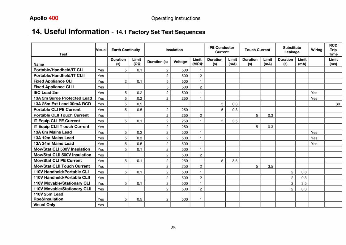
Apollo 400 Operating Instructions
25
14 Useful Information - 141 Factory Set Test Sequences
Test
Visual Earth Continuity Insulation PE Conductor
Current Touch Current
Substitute
Leakage Wiring
RCD
Trip
Time
Name
Duration
(s)
Limit
(ΩΩ) Duration (s) Voltage
Limit
(MΩΩ)
Duration
(s)
Limit
(mA)
Duration
(s)
Limit
(mA)
Duration
(s)
Limit
(mA)
Limit
(ms)
PortableHandheldIT CLI Yes 5 01 2 500 1
PortableHandheldIT CLII Yes 2 500 2
Fixed Appliance CLI Yes 2 01 5 500 1
Fixed Appliance CLII Yes 5 500 2
IEC Lead 2m Yes 5 02 2 500 1 Yes
13A 5m Surge Protected Lead Yes 5 02 2 250 1 Yes
13A 25m Ext Lead 30mA RCD Yes 5 05 5 08 30
Portable CLI PE Current Yes 5 05 2 250 1 5 08
Portable CLII Touch Current Yes 2 250 2 5 03
IT Equip CLI PE Current Yes 5 01 2 250 1 5 35
IT Equip CLII T ouch Current Yes 2 250 5 03
13A 6m Mains Lead Yes 5 02 2 500 1 Yes
13A 12m Mains Lead Yes 5 03 2 500 1 Yes
13A 24m Mains Lead Yes 5 05 2 500 1 Yes
MovStat CLI 500V Insulation Yes 5 01 2 500 1
MovStat CLII 500V Insulation Yes 2 500 2
MovStat CLI PE Current Yes 5 01 2 250 1 5 35
MovStat CLII Touch Current Yes 2 250 2 5 35
110V HandheldPortable CLI Yes 5 01 2 500 1 2 08
110V HandheldPortable CLII Yes 2 500 2 2 03
110V MovableStationary CLI Yes 5 01 2 500 1 2 35
110V MovableStationary CLII Yes 2 500 2 2 03
110V 25m Lead
RpeampInsulation Yes 5 05 2 500 1
Visual Only Yes
Apollo 400 Operating Instructions
26
142 Other Information
Parameter Default Min Max
Earth Continuity PF limit (Ω) 01 001 1999
Earth Continuity Duration (s) 5 2 30
Insulation Resistance PF limit (MΩ) 1 001 1999
Insulation Resistance Duration (s) 5 2 30
Substitute Leakage PF limit (mA) 075 025 15
Substitute Leakage Duration (s) 5 2 30
IEC Cord Earth Continuity PF limit
(ohms) 01 001 5
IEC Cord Insulation PF limit (MΩ) 1 001 1999
Touch Current PF limit (mA) 025 025 350
Touch Current Duration (s) 5 2 30
PE Conductor Current PF limit (mA) 075 025 1999
PE Conductor Current Duration (s) 5 2 30
External Adapter Continuity (Ω) 01 001 5
External Adapter Leakage (mA) 075 025 999
External Adapter Duration (s) 5 2 30
RCD 30mA trip time (ms) 200 1 2000
RCD 150mA trip time (ms) 40 1 40
Number of tests in a test sequence 1 60
Characters in a test sequence name 1 30
Characters in a User Test name 1 15
Characters in a User Test Unit 15
Total number of Test Sequences 25
Test Results (typical) 2000
Sites 50
Characters in Site name 1 15
Locations 50
Characters in Location name 1 15
Users (including admin) 2
Characters in User name 1 15
Comments List 50
Characters in Comment 25
Characters in Asset ID 1 15
Apollo 400 Operating Instructions
27
15 Environmental Conditions
The Apollo 400 has been designed to perform tests and measurements in a dry environment
Maximum barometric elevation for making measurements is 2000M
Pollution degree 2 according to IEC 60529
Electromagnetic compatibility (EMC) Interference immunity and emitted interference
conforming to IEC 61326-1
Operating temperature range of 0 to 40 degrees C without moisture condensation
Operating Altitude 0 to 2000 metres
16 Maintenance
161 Charging the battery pack
The battery pack will be charged whenever the Apollo 400 is connected to the mains supply
regardless of whether it is switched on or off
The typical charging current is set to 500mA but this may vary as the instrument also
includes pre-charge and top up charge modes
When no tests are being performed the battery pack will be fully re-charged after 7 hours
162 Securing the Apollo 400
Under certain conditions safe operation of the Apollo 400 can no longer be assumed
Visible damage of the instrument case
Incorrect measurement results
Recognisable abuse to the instrument due to prolonged storage under improper conditions
Recognisable abuse to the instrument due to extraordinary transportation stress
In these case the Apollo 400 should be immediately switched off disconnected from any test
and measurement function and secured to prevent any further use
163 Cleaning the Apollo 400
Clean the external case of the Apollo 400 with a dry clean cloth
Avoid using solvents and abrasive scouring agents to clean the external case of the Apollo
400
Apollo 400 Operating Instructions
28
164 Replacing the battery pack
Before opening the Apollo 400 battery compartment
ensure that all test leads and accessories are
disconnected
Power off the instrument
Disconnect all test leads and accessories
Position the instrument face down and remove the screw holding the battery compartment
cover in place
Remove the battery compartment cover
Remove the battery pack from the compartment and unplug the 4 way connector
Connect the 4 way connector of the new battery to the 4 way header in the battery
compartment put the battery pack into the compartment
Relocate the battery compartment cover and fasten in position with the battery compartment
screw
ONLY USE A REPLACEMENT BATTERY PACK THAT HAS BEEN SUPPLIED BY SEAWARD
OR A SEAWARD APPROVED DISTRIBUTOR
17 Support
The Apollo 400 must be registered with Seaward before support will be made available For Technical Support contact Tel (+44) 191 587 8718
For help or advice on Service and Calibration contact
CalibrationHouse Seaward Electronic Bracken Hill South West Industrial Estate Peterlee Co Durham SR8 2SW England Tel (+44) 191 5878739 (+44) 191 5878737 Email serviceseawardcouk
Calibration House is part of the Seaward Group
Apollo 400 Operating Instructions
29
171 Register your product here-
wwwseawardcouk 172 Calibration Services-
wwwcalibrationhousecouk Bracken Hill South West Industrial Estate Peterlee County Durham SR8 2SW Co Durham SR8 2SW England Tel (+44) 191 5863511 Some icons provided by Fat Cow (httpwwwfatcowcomfree-icons) Based in part on the work of the Qwt project (httpqwtsfnet)
Apollo 400A simple no-nonsense PAT tester with fast data entry and storage for up to 2000appliance records
Key Featuresn High definition colour displayn Store 2000 appliance recordsn Remote data transfer from field to office n Bluetooth connectivity
Electrical Test Functionsn Low current earth continuity test guaranteeing accurate measurement n Point to point testing (earth continuity and insulation resistance)n Insulation resistancen IEC lead testn Protective conductor currentn Touch currentn Load powercurrentn Alternative leakage currentn RCD testn Power socket test
Ideal Forn Electrical Contractorsn Facilities Managersn Operations Managers
Apollo 400 offers simple electrical safety testing with straightforward data entryusing the intuitive QWERTY keypad
A comprehensive range of electrical safety tests ensure compliance with theIET 4th Edition Code of Practice whilst remote data transfer and USB downloadmakes data management easy and efficient
The Apollo 400 is ideal for mid-volume PAT testing where detailed records arerequired
Streamline the PAT testing process further by using the Apollo 400 with acompatible label printer barcode scanner and PATGuard 3 software
wwwseawardcoukapollo400
Tel +44 (0) 191 587 8741Email salesseawardcouk
Requires optional accessory (part number 380A983)
Straightforward PAT testing with simple data managementApollo 400 offers a comprehensive suite of electrical safetytests to enable any workplace appliance to be tested including3-phase equipment fixed appliances and RCDs
The QWERTY keypad enables asset information to be entered quicklyand easily while a large colour display with an intuitive menu structure makesthe Apollo 400 simple to grasp Lightweight and small in size with battery or mainspower modes the Apollo 400 is good to go in seconds allowing more appliances to betested without downtime for boot-up or a battery re-charge
Superb software for total traceabilityApollo 400 has an internal memory capable of storing up to 2000electrical test records Its compatibility with Seawardrsquos PATGuard 3software means that complete test records are easily managed ona PC
Transfer data to the PC remotely using the Bluetooth function anda smartphone or download the results via a USB cable directly toa PC Once downloaded to PATGuard 3 it is easy to keep track ofthe history of test and inspections as well as produce reportscertificates and invoices ndash offering total peace of mind and quickereasier management of scheduling inspections and tests
Download a free trial at wwwseawardcoukpg3trial
wwwseawardcoukapollo400
Tel +44 (0) 191 587 8741Email salesseawardcouk
additional accessory required for point to point testing
u Accessory BundlesThe Apollo 400 is available to buy with a selectionof optional accessory bundles to help you get themost out of your tester
Apollo 400 is supplied as standard with a UKAScalibration certificate and a 2 yearmanufacturerrsquos warranty (subject to terms andconditions)
Greater efficiency through useful accessoriesAs with many Seaward PAT testers the Apollo 400 is compatible with arange of printers and barcode scanners further speeding up the processof asset recognition testing and labelling
Also available in this range
A multi-tasking and fully customisable PAT with additionalhealth and safety features and on-board camera forunrivalled record keeping
Apollo 600 includes a universal risk assessment tool andthe ability to store up to 50000 appliance records plus2000 images - providing visual evidence of testenvironments perfect for advanced record-keeping inorganisations with high-volume workplace test andinspection routines
Apollo 600Multi-tasking PAT tester with on-board camera
wwwseawardcoukapollo400
Tel +44 (0) 191 587 8741Email salesseawardcouk
A powerful PAT tester with a built-in PAT retest calculatorand flexible user-configurable sequences for recordingany non-electrical workplace test or inspection
The ability to customise a number of settings and a largememory to store up to 10000 appliance records makesthe Apollo 500 a versatile and dependable tool for highvolume PAT testing
Apollo 500A fast amp fully customisable and versatile PAT tester
Optional accessory bundles available Part Number
Elite Bundle n Test n Tag Elite 2 rugged portable printer
n Test n Tag printer labels x 4
n Bluetooth barcode scanner
n Apollo kit carry case
n 110V adapter
Includes Apollo 400 tester
380A978
Elite Bundle +Software
PLUS PATGuard 3 software 1yr licence 380A979
Pro Bundle n Test n Tag Pro lightweight portable printer
n Test n Tag printer labels x 4
n Bluetooth barcode scanner
n Apollo kit carry case
n 110V adapter
Includes Apollo 400 tester
380A980
Pro Bundle +Software PLUS PATGuard 3 software 1yr licence 380A981
wwwseawardcoukapollo400
Tel +44 (0) 191 587 8741Email salesseawardcouk
Apollo 400 Apollo 500 Apollo 600
General Features
Battery amp mains powered n n n
Colour Screen amp QWERTY keypad n n n
Large internal memory 2000 records 10000 records 50000 records
Scanner amp printer compatible n n n
Password controlled user accounts n n
Set up multiple user accounts with varyinglevels of privileges
n n
Clone facility to set up multiple testers n n
Checkbox supplied as standard n n
On-board user manual n n
Test amp InspectionFeatures
Auto-increment asset ID n n
PAT Setup option to allow for custom menus n n
Enter asset description after test usingkeypad or barcode scanner
n n n
Comprehensive electrical safety test features n n n
Point to point measurement (Rpe amp IR)
n
(optional
accessory
required)
n n
User configurable electrical testvisualinspection sequences 25 100 100
User set sites amp locations 50 100 100
Risk based retest period calculator n n
User definable comments lines against testrecords
n n
Configurable checklists for any workplacetest or inspection (user tests)
n n
On-board camera n
Universal risk assessment n
Health amp safety certificates n
Data Transfer
Bluetooth connectivity n n n
Barcode scanner connectivity n n n
Print Pass amp Fail labels n n n
Add your company logo to labels n n
Select from various label formats to print n n
Remote data transfer via mobile device n
(Android only)
n
(Android only)
n
(Android and iOS)
Download to PC via USB cable n n n
Filter results to be downloaded n n
Upload previous results to tester for retest n n
Data transfer via USB flash drive n
Apollo Series Comparison Chart
PAT TESTS
Earth ContinuityTest Current +- 200mA DC Display Range 001 ndash 1999ΩPass Value User Defined
Insulation ResistanceTest Voltage 500V 250VDC 1mA nominalDisplay Range 001MΩ - 1999MΩPass Value User Defined
IEC Lead TestTest Voltage 5VAC nominalTest Live Neutral Checks for oc sc and crossed
Protective Conductor CurrentLoad
Test Voltage Supply voltage maximum load current 16A Display Ranges 001mA to 1999mA Pass Value User Defined
Touch Current
Test Voltage Supply Voltage maximum load current 16ADisplay Range 000 ndash 350mA Pass Value User defined
Load PowerCurrent
Test Voltage Supply Voltage maximum load current 16ATest Duration Programmable up to a maximum of 255s depending on load ie max duration is reduced for high loadsDisplay Range 000kVA ndash 400kVA 000A ndash 1600A
Alternative Leakage Current
Test Voltages gt25VAC lt50VAC Display Range 000mA to 1999mAPass Value User Defined
RCD Test
Test Voltage 230V +10 -15Test Current 30mA 150mA rms sinusoidalDisplay Range 0ms - 2000ms (30mA) 0-40ms (150mA)Test Method Internal isolation to avoid tripping distribution board RCD
Power Socket Test
Voltage Range 207V ndash 253VACIndicates configuration of voltage potential-Line potential phase to earthLine potential phase to neutralLine potential neutral to earth
General
Memory Size 2000 recordsWeight 15kgDimensions 230mm x 150mm x 100mmPower Source Mains or rechargeable battery pack
Standard Accessories (supplied with Apollo 400)30 day free trial of PATGuard 3 software 1x red test lead and probe with crocodile clip05m IEC leadMains power leadUSB download cableQuick start guideUKAS calibration certificate
Optional Accessories Test n Tag Elite 2 Bluetooth printer with roll of small labels (339A995)Test n Tag Pro Bluetooth printer with roll of small labels (339A987)Roll of small labels (approx 350 off 52 x 25mm labels) (339A947)Additional black test lead and probe with crocodile clip (for point to point testing) (380A983)Bluetooth barcode scanner (339A923)110V test adaptor (270A076)110V to IEC adapter (344A050)Apollo checkbox (380A953)3 Phase Leakage Adaptor 5 Star 16A (391A920)3 Phase Leakage Adaptor 5 Star 32A (391A910)3 Phase Adapter Delta 4 pin 16A 415V (for Rpe amp IR) (209A910)3 Phase Adapter Star 5 pin 16A 415V (for Rpe amp IR) (209A911)3 Phase Adapter Delta 4 pin 32A 415V (for Rpe amp IR) (209A912)3 Phase Adapter Star 5 pin 32A 415V (for Rpe amp IR) (209A913)Professional Seaward kit bag (71G109)Apollo carry case (380A952)PATGuard 3 software ndash download 30 day free trial atwwwseawardcoukpg3trial
Part NumbersApollo 400 standard package 380A920Apollo 400 with Elite accessory bundle 380A978Apollo 400 with Elite accessory bundle amp PATGuard 3 one year licence380A979Apollo 400 with Pro accessory bundle 380A980Apollo 400 with Pro accessory bundle amp PATGuard 3 one year licence380A981
TrainingSeaward offer a range of PAT testing courses including City amp GuildsGo to wwwseawardcouktraining for more information
Services2 year warranty (subject to terms and conditions available atwwwseawardcoukwarranty24)Service amp Calibration by CalibrationhouseGo to wwwcalibrationhousecom for more information
Technical Specifications
Part of
Rev 12
wwwseawardcoukapollo400
Tel +44 (0) 191 587 8741Email salesseawardcouk
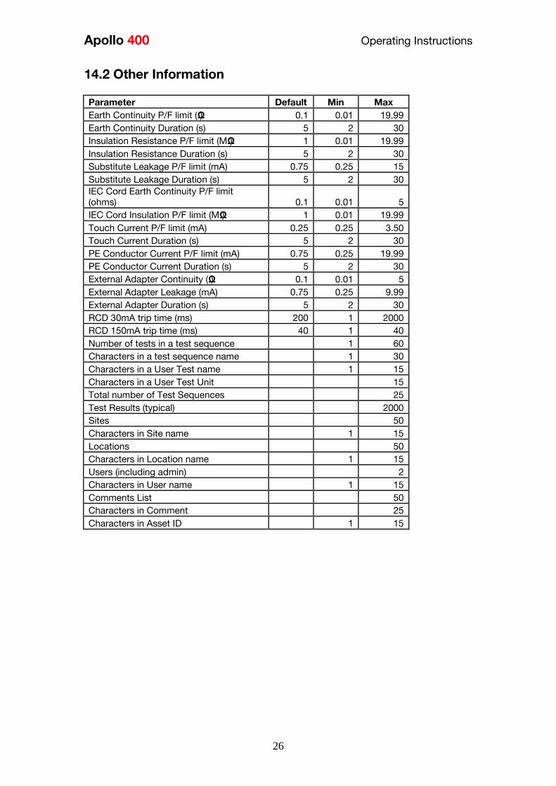
Apollo 400 Operating Instructions
26
142 Other Information
Parameter Default Min Max
Earth Continuity PF limit (Ω) 01 001 1999
Earth Continuity Duration (s) 5 2 30
Insulation Resistance PF limit (MΩ) 1 001 1999
Insulation Resistance Duration (s) 5 2 30
Substitute Leakage PF limit (mA) 075 025 15
Substitute Leakage Duration (s) 5 2 30
IEC Cord Earth Continuity PF limit
(ohms) 01 001 5
IEC Cord Insulation PF limit (MΩ) 1 001 1999
Touch Current PF limit (mA) 025 025 350
Touch Current Duration (s) 5 2 30
PE Conductor Current PF limit (mA) 075 025 1999
PE Conductor Current Duration (s) 5 2 30
External Adapter Continuity (Ω) 01 001 5
External Adapter Leakage (mA) 075 025 999
External Adapter Duration (s) 5 2 30
RCD 30mA trip time (ms) 200 1 2000
RCD 150mA trip time (ms) 40 1 40
Number of tests in a test sequence 1 60
Characters in a test sequence name 1 30
Characters in a User Test name 1 15
Characters in a User Test Unit 15
Total number of Test Sequences 25
Test Results (typical) 2000
Sites 50
Characters in Site name 1 15
Locations 50
Characters in Location name 1 15
Users (including admin) 2
Characters in User name 1 15
Comments List 50
Characters in Comment 25
Characters in Asset ID 1 15
Apollo 400 Operating Instructions
27
15 Environmental Conditions
The Apollo 400 has been designed to perform tests and measurements in a dry environment
Maximum barometric elevation for making measurements is 2000M
Pollution degree 2 according to IEC 60529
Electromagnetic compatibility (EMC) Interference immunity and emitted interference
conforming to IEC 61326-1
Operating temperature range of 0 to 40 degrees C without moisture condensation
Operating Altitude 0 to 2000 metres
16 Maintenance
161 Charging the battery pack
The battery pack will be charged whenever the Apollo 400 is connected to the mains supply
regardless of whether it is switched on or off
The typical charging current is set to 500mA but this may vary as the instrument also
includes pre-charge and top up charge modes
When no tests are being performed the battery pack will be fully re-charged after 7 hours
162 Securing the Apollo 400
Under certain conditions safe operation of the Apollo 400 can no longer be assumed
Visible damage of the instrument case
Incorrect measurement results
Recognisable abuse to the instrument due to prolonged storage under improper conditions
Recognisable abuse to the instrument due to extraordinary transportation stress
In these case the Apollo 400 should be immediately switched off disconnected from any test
and measurement function and secured to prevent any further use
163 Cleaning the Apollo 400
Clean the external case of the Apollo 400 with a dry clean cloth
Avoid using solvents and abrasive scouring agents to clean the external case of the Apollo
400
Apollo 400 Operating Instructions
28
164 Replacing the battery pack
Before opening the Apollo 400 battery compartment
ensure that all test leads and accessories are
disconnected
Power off the instrument
Disconnect all test leads and accessories
Position the instrument face down and remove the screw holding the battery compartment
cover in place
Remove the battery compartment cover
Remove the battery pack from the compartment and unplug the 4 way connector
Connect the 4 way connector of the new battery to the 4 way header in the battery
compartment put the battery pack into the compartment
Relocate the battery compartment cover and fasten in position with the battery compartment
screw
ONLY USE A REPLACEMENT BATTERY PACK THAT HAS BEEN SUPPLIED BY SEAWARD
OR A SEAWARD APPROVED DISTRIBUTOR
17 Support
The Apollo 400 must be registered with Seaward before support will be made available For Technical Support contact Tel (+44) 191 587 8718
For help or advice on Service and Calibration contact
CalibrationHouse Seaward Electronic Bracken Hill South West Industrial Estate Peterlee Co Durham SR8 2SW England Tel (+44) 191 5878739 (+44) 191 5878737 Email serviceseawardcouk
Calibration House is part of the Seaward Group
Apollo 400 Operating Instructions
29
171 Register your product here-
wwwseawardcouk 172 Calibration Services-
wwwcalibrationhousecouk Bracken Hill South West Industrial Estate Peterlee County Durham SR8 2SW Co Durham SR8 2SW England Tel (+44) 191 5863511 Some icons provided by Fat Cow (httpwwwfatcowcomfree-icons) Based in part on the work of the Qwt project (httpqwtsfnet)
Apollo 400A simple no-nonsense PAT tester with fast data entry and storage for up to 2000appliance records
Key Featuresn High definition colour displayn Store 2000 appliance recordsn Remote data transfer from field to office n Bluetooth connectivity
Electrical Test Functionsn Low current earth continuity test guaranteeing accurate measurement n Point to point testing (earth continuity and insulation resistance)n Insulation resistancen IEC lead testn Protective conductor currentn Touch currentn Load powercurrentn Alternative leakage currentn RCD testn Power socket test
Ideal Forn Electrical Contractorsn Facilities Managersn Operations Managers
Apollo 400 offers simple electrical safety testing with straightforward data entryusing the intuitive QWERTY keypad
A comprehensive range of electrical safety tests ensure compliance with theIET 4th Edition Code of Practice whilst remote data transfer and USB downloadmakes data management easy and efficient
The Apollo 400 is ideal for mid-volume PAT testing where detailed records arerequired
Streamline the PAT testing process further by using the Apollo 400 with acompatible label printer barcode scanner and PATGuard 3 software
wwwseawardcoukapollo400
Tel +44 (0) 191 587 8741Email salesseawardcouk
Requires optional accessory (part number 380A983)
Straightforward PAT testing with simple data managementApollo 400 offers a comprehensive suite of electrical safetytests to enable any workplace appliance to be tested including3-phase equipment fixed appliances and RCDs
The QWERTY keypad enables asset information to be entered quicklyand easily while a large colour display with an intuitive menu structure makesthe Apollo 400 simple to grasp Lightweight and small in size with battery or mainspower modes the Apollo 400 is good to go in seconds allowing more appliances to betested without downtime for boot-up or a battery re-charge
Superb software for total traceabilityApollo 400 has an internal memory capable of storing up to 2000electrical test records Its compatibility with Seawardrsquos PATGuard 3software means that complete test records are easily managed ona PC
Transfer data to the PC remotely using the Bluetooth function anda smartphone or download the results via a USB cable directly toa PC Once downloaded to PATGuard 3 it is easy to keep track ofthe history of test and inspections as well as produce reportscertificates and invoices ndash offering total peace of mind and quickereasier management of scheduling inspections and tests
Download a free trial at wwwseawardcoukpg3trial
wwwseawardcoukapollo400
Tel +44 (0) 191 587 8741Email salesseawardcouk
additional accessory required for point to point testing
u Accessory BundlesThe Apollo 400 is available to buy with a selectionof optional accessory bundles to help you get themost out of your tester
Apollo 400 is supplied as standard with a UKAScalibration certificate and a 2 yearmanufacturerrsquos warranty (subject to terms andconditions)
Greater efficiency through useful accessoriesAs with many Seaward PAT testers the Apollo 400 is compatible with arange of printers and barcode scanners further speeding up the processof asset recognition testing and labelling
Also available in this range
A multi-tasking and fully customisable PAT with additionalhealth and safety features and on-board camera forunrivalled record keeping
Apollo 600 includes a universal risk assessment tool andthe ability to store up to 50000 appliance records plus2000 images - providing visual evidence of testenvironments perfect for advanced record-keeping inorganisations with high-volume workplace test andinspection routines
Apollo 600Multi-tasking PAT tester with on-board camera
wwwseawardcoukapollo400
Tel +44 (0) 191 587 8741Email salesseawardcouk
A powerful PAT tester with a built-in PAT retest calculatorand flexible user-configurable sequences for recordingany non-electrical workplace test or inspection
The ability to customise a number of settings and a largememory to store up to 10000 appliance records makesthe Apollo 500 a versatile and dependable tool for highvolume PAT testing
Apollo 500A fast amp fully customisable and versatile PAT tester
Optional accessory bundles available Part Number
Elite Bundle n Test n Tag Elite 2 rugged portable printer
n Test n Tag printer labels x 4
n Bluetooth barcode scanner
n Apollo kit carry case
n 110V adapter
Includes Apollo 400 tester
380A978
Elite Bundle +Software
PLUS PATGuard 3 software 1yr licence 380A979
Pro Bundle n Test n Tag Pro lightweight portable printer
n Test n Tag printer labels x 4
n Bluetooth barcode scanner
n Apollo kit carry case
n 110V adapter
Includes Apollo 400 tester
380A980
Pro Bundle +Software PLUS PATGuard 3 software 1yr licence 380A981
wwwseawardcoukapollo400
Tel +44 (0) 191 587 8741Email salesseawardcouk
Apollo 400 Apollo 500 Apollo 600
General Features
Battery amp mains powered n n n
Colour Screen amp QWERTY keypad n n n
Large internal memory 2000 records 10000 records 50000 records
Scanner amp printer compatible n n n
Password controlled user accounts n n
Set up multiple user accounts with varyinglevels of privileges
n n
Clone facility to set up multiple testers n n
Checkbox supplied as standard n n
On-board user manual n n
Test amp InspectionFeatures
Auto-increment asset ID n n
PAT Setup option to allow for custom menus n n
Enter asset description after test usingkeypad or barcode scanner
n n n
Comprehensive electrical safety test features n n n
Point to point measurement (Rpe amp IR)
n
(optional
accessory
required)
n n
User configurable electrical testvisualinspection sequences 25 100 100
User set sites amp locations 50 100 100
Risk based retest period calculator n n
User definable comments lines against testrecords
n n
Configurable checklists for any workplacetest or inspection (user tests)
n n
On-board camera n
Universal risk assessment n
Health amp safety certificates n
Data Transfer
Bluetooth connectivity n n n
Barcode scanner connectivity n n n
Print Pass amp Fail labels n n n
Add your company logo to labels n n
Select from various label formats to print n n
Remote data transfer via mobile device n
(Android only)
n
(Android only)
n
(Android and iOS)
Download to PC via USB cable n n n
Filter results to be downloaded n n
Upload previous results to tester for retest n n
Data transfer via USB flash drive n
Apollo Series Comparison Chart
PAT TESTS
Earth ContinuityTest Current +- 200mA DC Display Range 001 ndash 1999ΩPass Value User Defined
Insulation ResistanceTest Voltage 500V 250VDC 1mA nominalDisplay Range 001MΩ - 1999MΩPass Value User Defined
IEC Lead TestTest Voltage 5VAC nominalTest Live Neutral Checks for oc sc and crossed
Protective Conductor CurrentLoad
Test Voltage Supply voltage maximum load current 16A Display Ranges 001mA to 1999mA Pass Value User Defined
Touch Current
Test Voltage Supply Voltage maximum load current 16ADisplay Range 000 ndash 350mA Pass Value User defined
Load PowerCurrent
Test Voltage Supply Voltage maximum load current 16ATest Duration Programmable up to a maximum of 255s depending on load ie max duration is reduced for high loadsDisplay Range 000kVA ndash 400kVA 000A ndash 1600A
Alternative Leakage Current
Test Voltages gt25VAC lt50VAC Display Range 000mA to 1999mAPass Value User Defined
RCD Test
Test Voltage 230V +10 -15Test Current 30mA 150mA rms sinusoidalDisplay Range 0ms - 2000ms (30mA) 0-40ms (150mA)Test Method Internal isolation to avoid tripping distribution board RCD
Power Socket Test
Voltage Range 207V ndash 253VACIndicates configuration of voltage potential-Line potential phase to earthLine potential phase to neutralLine potential neutral to earth
General
Memory Size 2000 recordsWeight 15kgDimensions 230mm x 150mm x 100mmPower Source Mains or rechargeable battery pack
Standard Accessories (supplied with Apollo 400)30 day free trial of PATGuard 3 software 1x red test lead and probe with crocodile clip05m IEC leadMains power leadUSB download cableQuick start guideUKAS calibration certificate
Optional Accessories Test n Tag Elite 2 Bluetooth printer with roll of small labels (339A995)Test n Tag Pro Bluetooth printer with roll of small labels (339A987)Roll of small labels (approx 350 off 52 x 25mm labels) (339A947)Additional black test lead and probe with crocodile clip (for point to point testing) (380A983)Bluetooth barcode scanner (339A923)110V test adaptor (270A076)110V to IEC adapter (344A050)Apollo checkbox (380A953)3 Phase Leakage Adaptor 5 Star 16A (391A920)3 Phase Leakage Adaptor 5 Star 32A (391A910)3 Phase Adapter Delta 4 pin 16A 415V (for Rpe amp IR) (209A910)3 Phase Adapter Star 5 pin 16A 415V (for Rpe amp IR) (209A911)3 Phase Adapter Delta 4 pin 32A 415V (for Rpe amp IR) (209A912)3 Phase Adapter Star 5 pin 32A 415V (for Rpe amp IR) (209A913)Professional Seaward kit bag (71G109)Apollo carry case (380A952)PATGuard 3 software ndash download 30 day free trial atwwwseawardcoukpg3trial
Part NumbersApollo 400 standard package 380A920Apollo 400 with Elite accessory bundle 380A978Apollo 400 with Elite accessory bundle amp PATGuard 3 one year licence380A979Apollo 400 with Pro accessory bundle 380A980Apollo 400 with Pro accessory bundle amp PATGuard 3 one year licence380A981
TrainingSeaward offer a range of PAT testing courses including City amp GuildsGo to wwwseawardcouktraining for more information
Services2 year warranty (subject to terms and conditions available atwwwseawardcoukwarranty24)Service amp Calibration by CalibrationhouseGo to wwwcalibrationhousecom for more information
Technical Specifications
Part of
Rev 12
wwwseawardcoukapollo400
Tel +44 (0) 191 587 8741Email salesseawardcouk
Apollo 400 Operating Instructions
29
171 Register your product here-
wwwseawardcouk 172 Calibration Services-
wwwcalibrationhousecouk Bracken Hill South West Industrial Estate Peterlee County Durham SR8 2SW Co Durham SR8 2SW England Tel (+44) 191 5863511 Some icons provided by Fat Cow (httpwwwfatcowcomfree-icons) Based in part on the work of the Qwt project (httpqwtsfnet)
Apollo 400A simple no-nonsense PAT tester with fast data entry and storage for up to 2000appliance records
Key Featuresn High definition colour displayn Store 2000 appliance recordsn Remote data transfer from field to office n Bluetooth connectivity
Electrical Test Functionsn Low current earth continuity test guaranteeing accurate measurement n Point to point testing (earth continuity and insulation resistance)n Insulation resistancen IEC lead testn Protective conductor currentn Touch currentn Load powercurrentn Alternative leakage currentn RCD testn Power socket test
Ideal Forn Electrical Contractorsn Facilities Managersn Operations Managers
Apollo 400 offers simple electrical safety testing with straightforward data entryusing the intuitive QWERTY keypad
A comprehensive range of electrical safety tests ensure compliance with theIET 4th Edition Code of Practice whilst remote data transfer and USB downloadmakes data management easy and efficient
The Apollo 400 is ideal for mid-volume PAT testing where detailed records arerequired
Streamline the PAT testing process further by using the Apollo 400 with acompatible label printer barcode scanner and PATGuard 3 software
wwwseawardcoukapollo400
Tel +44 (0) 191 587 8741Email salesseawardcouk
Requires optional accessory (part number 380A983)
Straightforward PAT testing with simple data managementApollo 400 offers a comprehensive suite of electrical safetytests to enable any workplace appliance to be tested including3-phase equipment fixed appliances and RCDs
The QWERTY keypad enables asset information to be entered quicklyand easily while a large colour display with an intuitive menu structure makesthe Apollo 400 simple to grasp Lightweight and small in size with battery or mainspower modes the Apollo 400 is good to go in seconds allowing more appliances to betested without downtime for boot-up or a battery re-charge
Superb software for total traceabilityApollo 400 has an internal memory capable of storing up to 2000electrical test records Its compatibility with Seawardrsquos PATGuard 3software means that complete test records are easily managed ona PC
Transfer data to the PC remotely using the Bluetooth function anda smartphone or download the results via a USB cable directly toa PC Once downloaded to PATGuard 3 it is easy to keep track ofthe history of test and inspections as well as produce reportscertificates and invoices ndash offering total peace of mind and quickereasier management of scheduling inspections and tests
Download a free trial at wwwseawardcoukpg3trial
wwwseawardcoukapollo400
Tel +44 (0) 191 587 8741Email salesseawardcouk
additional accessory required for point to point testing
u Accessory BundlesThe Apollo 400 is available to buy with a selectionof optional accessory bundles to help you get themost out of your tester
Apollo 400 is supplied as standard with a UKAScalibration certificate and a 2 yearmanufacturerrsquos warranty (subject to terms andconditions)
Greater efficiency through useful accessoriesAs with many Seaward PAT testers the Apollo 400 is compatible with arange of printers and barcode scanners further speeding up the processof asset recognition testing and labelling
Also available in this range
A multi-tasking and fully customisable PAT with additionalhealth and safety features and on-board camera forunrivalled record keeping
Apollo 600 includes a universal risk assessment tool andthe ability to store up to 50000 appliance records plus2000 images - providing visual evidence of testenvironments perfect for advanced record-keeping inorganisations with high-volume workplace test andinspection routines
Apollo 600Multi-tasking PAT tester with on-board camera
wwwseawardcoukapollo400
Tel +44 (0) 191 587 8741Email salesseawardcouk
A powerful PAT tester with a built-in PAT retest calculatorand flexible user-configurable sequences for recordingany non-electrical workplace test or inspection
The ability to customise a number of settings and a largememory to store up to 10000 appliance records makesthe Apollo 500 a versatile and dependable tool for highvolume PAT testing
Apollo 500A fast amp fully customisable and versatile PAT tester
Optional accessory bundles available Part Number
Elite Bundle n Test n Tag Elite 2 rugged portable printer
n Test n Tag printer labels x 4
n Bluetooth barcode scanner
n Apollo kit carry case
n 110V adapter
Includes Apollo 400 tester
380A978
Elite Bundle +Software
PLUS PATGuard 3 software 1yr licence 380A979
Pro Bundle n Test n Tag Pro lightweight portable printer
n Test n Tag printer labels x 4
n Bluetooth barcode scanner
n Apollo kit carry case
n 110V adapter
Includes Apollo 400 tester
380A980
Pro Bundle +Software PLUS PATGuard 3 software 1yr licence 380A981
wwwseawardcoukapollo400
Tel +44 (0) 191 587 8741Email salesseawardcouk
Apollo 400 Apollo 500 Apollo 600
General Features
Battery amp mains powered n n n
Colour Screen amp QWERTY keypad n n n
Large internal memory 2000 records 10000 records 50000 records
Scanner amp printer compatible n n n
Password controlled user accounts n n
Set up multiple user accounts with varyinglevels of privileges
n n
Clone facility to set up multiple testers n n
Checkbox supplied as standard n n
On-board user manual n n
Test amp InspectionFeatures
Auto-increment asset ID n n
PAT Setup option to allow for custom menus n n
Enter asset description after test usingkeypad or barcode scanner
n n n
Comprehensive electrical safety test features n n n
Point to point measurement (Rpe amp IR)
n
(optional
accessory
required)
n n
User configurable electrical testvisualinspection sequences 25 100 100
User set sites amp locations 50 100 100
Risk based retest period calculator n n
User definable comments lines against testrecords
n n
Configurable checklists for any workplacetest or inspection (user tests)
n n
On-board camera n
Universal risk assessment n
Health amp safety certificates n
Data Transfer
Bluetooth connectivity n n n
Barcode scanner connectivity n n n
Print Pass amp Fail labels n n n
Add your company logo to labels n n
Select from various label formats to print n n
Remote data transfer via mobile device n
(Android only)
n
(Android only)
n
(Android and iOS)
Download to PC via USB cable n n n
Filter results to be downloaded n n
Upload previous results to tester for retest n n
Data transfer via USB flash drive n
Apollo Series Comparison Chart
PAT TESTS
Earth ContinuityTest Current +- 200mA DC Display Range 001 ndash 1999ΩPass Value User Defined
Insulation ResistanceTest Voltage 500V 250VDC 1mA nominalDisplay Range 001MΩ - 1999MΩPass Value User Defined
IEC Lead TestTest Voltage 5VAC nominalTest Live Neutral Checks for oc sc and crossed
Protective Conductor CurrentLoad
Test Voltage Supply voltage maximum load current 16A Display Ranges 001mA to 1999mA Pass Value User Defined
Touch Current
Test Voltage Supply Voltage maximum load current 16ADisplay Range 000 ndash 350mA Pass Value User defined
Load PowerCurrent
Test Voltage Supply Voltage maximum load current 16ATest Duration Programmable up to a maximum of 255s depending on load ie max duration is reduced for high loadsDisplay Range 000kVA ndash 400kVA 000A ndash 1600A
Alternative Leakage Current
Test Voltages gt25VAC lt50VAC Display Range 000mA to 1999mAPass Value User Defined
RCD Test
Test Voltage 230V +10 -15Test Current 30mA 150mA rms sinusoidalDisplay Range 0ms - 2000ms (30mA) 0-40ms (150mA)Test Method Internal isolation to avoid tripping distribution board RCD
Power Socket Test
Voltage Range 207V ndash 253VACIndicates configuration of voltage potential-Line potential phase to earthLine potential phase to neutralLine potential neutral to earth
General
Memory Size 2000 recordsWeight 15kgDimensions 230mm x 150mm x 100mmPower Source Mains or rechargeable battery pack
Standard Accessories (supplied with Apollo 400)30 day free trial of PATGuard 3 software 1x red test lead and probe with crocodile clip05m IEC leadMains power leadUSB download cableQuick start guideUKAS calibration certificate
Optional Accessories Test n Tag Elite 2 Bluetooth printer with roll of small labels (339A995)Test n Tag Pro Bluetooth printer with roll of small labels (339A987)Roll of small labels (approx 350 off 52 x 25mm labels) (339A947)Additional black test lead and probe with crocodile clip (for point to point testing) (380A983)Bluetooth barcode scanner (339A923)110V test adaptor (270A076)110V to IEC adapter (344A050)Apollo checkbox (380A953)3 Phase Leakage Adaptor 5 Star 16A (391A920)3 Phase Leakage Adaptor 5 Star 32A (391A910)3 Phase Adapter Delta 4 pin 16A 415V (for Rpe amp IR) (209A910)3 Phase Adapter Star 5 pin 16A 415V (for Rpe amp IR) (209A911)3 Phase Adapter Delta 4 pin 32A 415V (for Rpe amp IR) (209A912)3 Phase Adapter Star 5 pin 32A 415V (for Rpe amp IR) (209A913)Professional Seaward kit bag (71G109)Apollo carry case (380A952)PATGuard 3 software ndash download 30 day free trial atwwwseawardcoukpg3trial
Part NumbersApollo 400 standard package 380A920Apollo 400 with Elite accessory bundle 380A978Apollo 400 with Elite accessory bundle amp PATGuard 3 one year licence380A979Apollo 400 with Pro accessory bundle 380A980Apollo 400 with Pro accessory bundle amp PATGuard 3 one year licence380A981
TrainingSeaward offer a range of PAT testing courses including City amp GuildsGo to wwwseawardcouktraining for more information
Services2 year warranty (subject to terms and conditions available atwwwseawardcoukwarranty24)Service amp Calibration by CalibrationhouseGo to wwwcalibrationhousecom for more information
Technical Specifications
Part of
Rev 12
wwwseawardcoukapollo400
Tel +44 (0) 191 587 8741Email salesseawardcouk
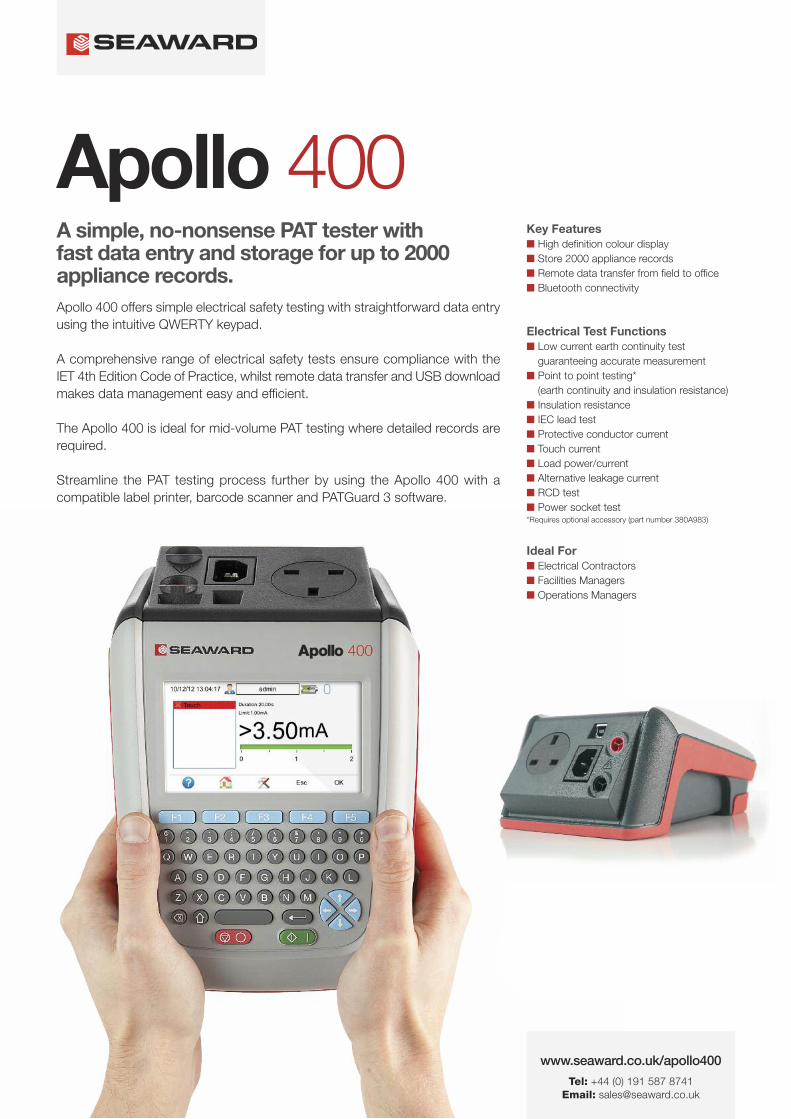
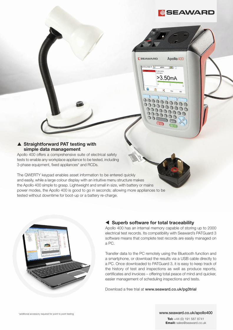
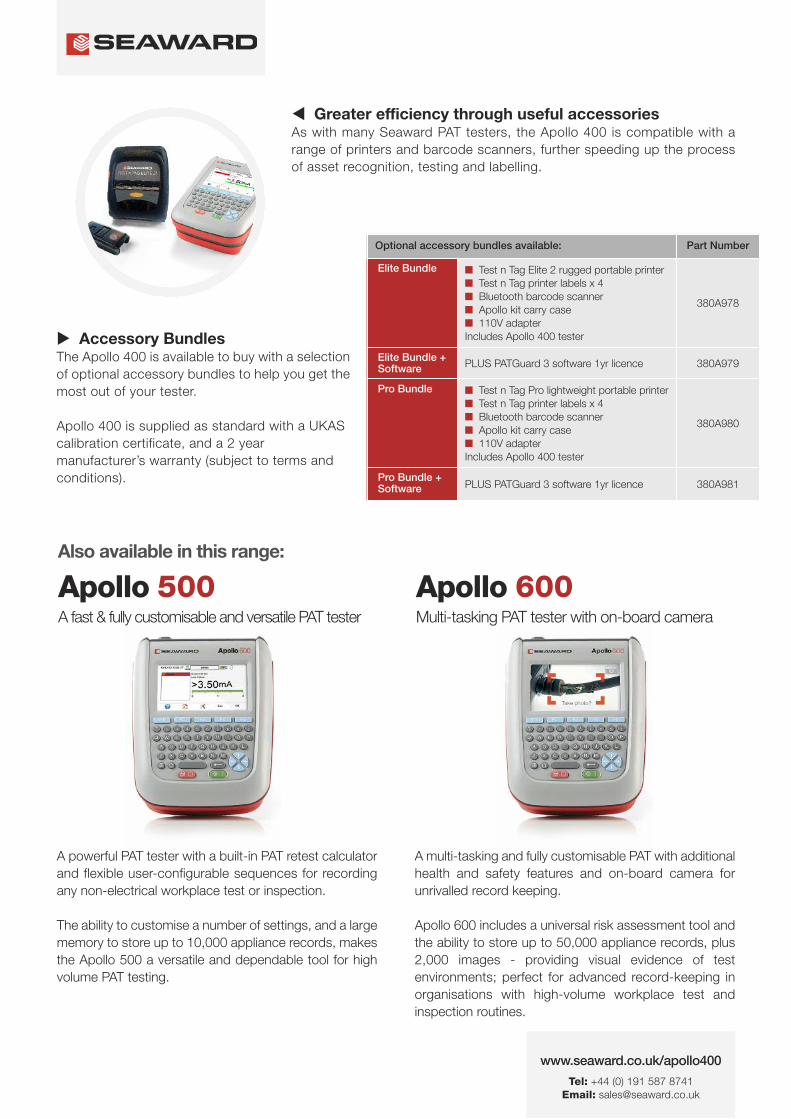
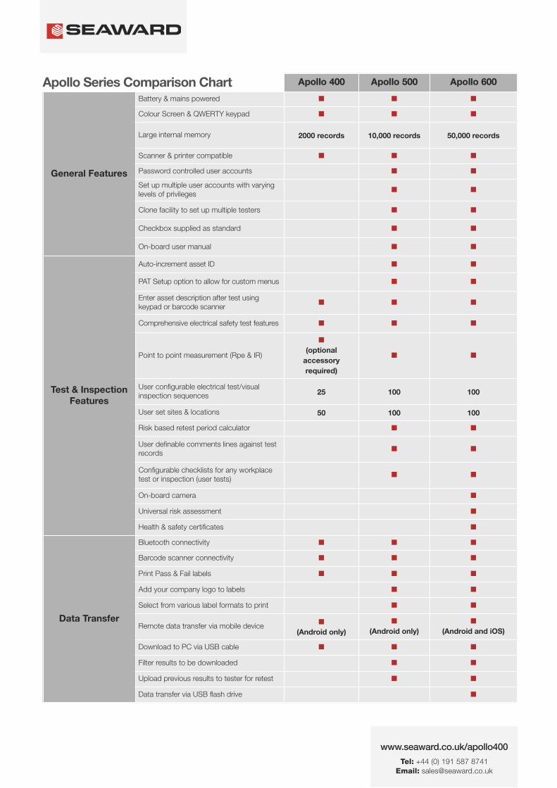
wwwseawardcoukapollo400
Tel +44 (0) 191 587 8741Email salesseawardcouk
Apollo 400 Apollo 500 Apollo 600
General Features
Battery amp mains powered n n n
Colour Screen amp QWERTY keypad n n n
Large internal memory 2000 records 10000 records 50000 records
Scanner amp printer compatible n n n
Password controlled user accounts n n
Set up multiple user accounts with varyinglevels of privileges
n n
Clone facility to set up multiple testers n n
Checkbox supplied as standard n n
On-board user manual n n
Test amp InspectionFeatures
Auto-increment asset ID n n
PAT Setup option to allow for custom menus n n
Enter asset description after test usingkeypad or barcode scanner
n n n
Comprehensive electrical safety test features n n n
Point to point measurement (Rpe amp IR)
n
(optional
accessory
required)
n n
User configurable electrical testvisualinspection sequences 25 100 100
User set sites amp locations 50 100 100
Risk based retest period calculator n n
User definable comments lines against testrecords
n n
Configurable checklists for any workplacetest or inspection (user tests)
n n
On-board camera n
Universal risk assessment n
Health amp safety certificates n
Data Transfer
Bluetooth connectivity n n n
Barcode scanner connectivity n n n
Print Pass amp Fail labels n n n
Add your company logo to labels n n
Select from various label formats to print n n
Remote data transfer via mobile device n
(Android only)
n
(Android only)
n
(Android and iOS)
Download to PC via USB cable n n n
Filter results to be downloaded n n
Upload previous results to tester for retest n n
Data transfer via USB flash drive n
Apollo Series Comparison Chart
PAT TESTS
Earth ContinuityTest Current +- 200mA DC Display Range 001 ndash 1999ΩPass Value User Defined
Insulation ResistanceTest Voltage 500V 250VDC 1mA nominalDisplay Range 001MΩ - 1999MΩPass Value User Defined
IEC Lead TestTest Voltage 5VAC nominalTest Live Neutral Checks for oc sc and crossed
Protective Conductor CurrentLoad
Test Voltage Supply voltage maximum load current 16A Display Ranges 001mA to 1999mA Pass Value User Defined
Touch Current
Test Voltage Supply Voltage maximum load current 16ADisplay Range 000 ndash 350mA Pass Value User defined
Load PowerCurrent
Test Voltage Supply Voltage maximum load current 16ATest Duration Programmable up to a maximum of 255s depending on load ie max duration is reduced for high loadsDisplay Range 000kVA ndash 400kVA 000A ndash 1600A
Alternative Leakage Current
Test Voltages gt25VAC lt50VAC Display Range 000mA to 1999mAPass Value User Defined
RCD Test
Test Voltage 230V +10 -15Test Current 30mA 150mA rms sinusoidalDisplay Range 0ms - 2000ms (30mA) 0-40ms (150mA)Test Method Internal isolation to avoid tripping distribution board RCD
Power Socket Test
Voltage Range 207V ndash 253VACIndicates configuration of voltage potential-Line potential phase to earthLine potential phase to neutralLine potential neutral to earth
General
Memory Size 2000 recordsWeight 15kgDimensions 230mm x 150mm x 100mmPower Source Mains or rechargeable battery pack
Standard Accessories (supplied with Apollo 400)30 day free trial of PATGuard 3 software 1x red test lead and probe with crocodile clip05m IEC leadMains power leadUSB download cableQuick start guideUKAS calibration certificate
Optional Accessories Test n Tag Elite 2 Bluetooth printer with roll of small labels (339A995)Test n Tag Pro Bluetooth printer with roll of small labels (339A987)Roll of small labels (approx 350 off 52 x 25mm labels) (339A947)Additional black test lead and probe with crocodile clip (for point to point testing) (380A983)Bluetooth barcode scanner (339A923)110V test adaptor (270A076)110V to IEC adapter (344A050)Apollo checkbox (380A953)3 Phase Leakage Adaptor 5 Star 16A (391A920)3 Phase Leakage Adaptor 5 Star 32A (391A910)3 Phase Adapter Delta 4 pin 16A 415V (for Rpe amp IR) (209A910)3 Phase Adapter Star 5 pin 16A 415V (for Rpe amp IR) (209A911)3 Phase Adapter Delta 4 pin 32A 415V (for Rpe amp IR) (209A912)3 Phase Adapter Star 5 pin 32A 415V (for Rpe amp IR) (209A913)Professional Seaward kit bag (71G109)Apollo carry case (380A952)PATGuard 3 software ndash download 30 day free trial atwwwseawardcoukpg3trial
Part NumbersApollo 400 standard package 380A920Apollo 400 with Elite accessory bundle 380A978Apollo 400 with Elite accessory bundle amp PATGuard 3 one year licence380A979Apollo 400 with Pro accessory bundle 380A980Apollo 400 with Pro accessory bundle amp PATGuard 3 one year licence380A981
TrainingSeaward offer a range of PAT testing courses including City amp GuildsGo to wwwseawardcouktraining for more information
Services2 year warranty (subject to terms and conditions available atwwwseawardcoukwarranty24)Service amp Calibration by CalibrationhouseGo to wwwcalibrationhousecom for more information
Technical Specifications
Part of
Rev 12
wwwseawardcoukapollo400
Tel +44 (0) 191 587 8741Email salesseawardcouk