Embed Size (px)
Citation preview

Guide To Advanced Control Systems
API RECOMMENDED PRACTICE 557 FIRST EDITION, DECEMBER 2000
American Petroleum Institute
Helping You Get The Job Done Right?
COPYRIGHT American Petroleum InstituteLicensed by Information Handling ServicesCOPYRIGHT American Petroleum InstituteLicensed by Information Handling Services

COPYRIGHT American Petroleum InstituteLicensed by Information Handling ServicesCOPYRIGHT American Petroleum InstituteLicensed by Information Handling Services

Guide To Advanced Control Systems
Downstream Segment
API RECOMMENDED PRACTICE 557 FIRST EDITION, DECEMBER 2000
American Petroleum Institute
Helping You Get The Job Done Right.""
COPYRIGHT American Petroleum InstituteLicensed by Information Handling ServicesCOPYRIGHT American Petroleum InstituteLicensed by Information Handling Services
SPECIAL NOTES
API publications necessarily address problems of a general nature. With respect to partic- ular circumstances, local, state, and federal laws and regulations should be reviewed.
API is not undertaking to meet the duties of employers, manufacturers, or suppliers to warn and properly train and equip their employees, and others exposed, concerning health and safety risks and precautions, nor undertaking their obligations under local, state, or fed- eral laws.
Information concerning safety and health risks and proper precautions with respect to par- ticular materials and conditions should be obtained from the employer, the manufacturer or supplier of that material, or the material safety data sheet.
Nothing contained in any API publication is to be construed as granting any right, by implication or otherwise, for the manufacture, sale, or use of any method, apparatus, or prod- uct covered by letters patent. Neither should anything contained in the publication be con- strued as insuring anyone against liability for infringement of letters patent.
Generally, API standards are reviewed and revised, reafhed, or withdrawn at least every five years. Sometimes a one-time extension of up to two years will be added to this review cycle. This publication will no longer be in effect five years after its publication date as an operative API standard or, where an extension has been granted, upon republication. Status of the publication can be ascertained from the API Standardization Manager [telephone (202) 682-8000]. A catalog of API publications and materials is published annudy and updated quarterly by API, 1220 L Street, N.W., Washington, D.C. 20005.
This document was produced under API standardization procedures that ensure appropri- ate notification and participation in the developmental process and is designated as an API standard. Questions concerning the interpretation of the content of this standard or com- ments and questions concerning the procedures under which this standard was developed should be directed in writing to the API Standardization Manager, American Petroleum Insti- tute, 1220 L Street, N.W., Washington, D.C. 20005. Requests for permission to reproduce or translate d or any part of the material published herein should also be addressed to the gen- eral manager.
API standards are published to facilitate the broad availability of proven, sound engineer- ing and operating practices. These standards are not intended to obviate the need for apply- ing sound engineering judgment regarding when and where these standards should be utilized. The formulation and publication of API standards is not intended in any way to inhibit anyone from using any other practices.
Any manufacturer marking equipment or materials in conformance with the marking requirements of an API standard is solely responsible for complying with all the applicable requirements of that standard. API does not represent, warrant, or guarantee that such prod- ucts do in fact conform to the applicable API standard.
All rights resewed. No part of this work may be reproduced, stored in a retrieval system, or transmitted by any means, electronic, mechanical, photocopying, recording, or otherwise,
without prior written permission fiom the publisher. Contact the Publisher, API Publishing Services, 1220 L Street, N.W, Washington, D.C. 20005.
Copyright O 2000American Petroleum Institute
COPYRIGHT American Petroleum InstituteLicensed by Information Handling ServicesCOPYRIGHT American Petroleum InstituteLicensed by Information Handling Services

FOREWORD
API publications may be used by anyone desiring to do so. Every effort has been made by the Institute to assure the accuracy and reliability of the data contained in them; however, the Institute makes no representation, warranty, or guarantee in connection with this publication and hereby expressly disclaims any liability or responsibility for loss or damage resulting from its use or for the violation of any federal, state, or municipal regulation with which this publication may conñict.
Suggested revisions are invited and should be submitted to the API Standardization Man- ager, American Petroleum Institute, 1220 L Street, N.W., Washington, D.C. 20005.
... 111
COPYRIGHT American Petroleum InstituteLicensed by Information Handling ServicesCOPYRIGHT American Petroleum InstituteLicensed by Information Handling Services

COPYRIGHT American Petroleum InstituteLicensed by Information Handling ServicesCOPYRIGHT American Petroleum InstituteLicensed by Information Handling Services

CONTENTS
Page
1 GENERAL ............................................................ 1 1.1 Introduction ...................................................... 1 1.2 Scope ........................................................... 1 1.3 Definitions ....................................................... 1
2 CONTROL SYSTEM FUNCTIONS AND TYPES ........................... 3 Regulatory Control System Functions ................................. 3
2.3 Optimizers ....................................................... 5 2.4 ExpertSystems .................................................... 6
Fuzzy Logic Systems ............................................... 6 Batch and Sequence Systems ........................................ 6
Oil Movement Systems ............................................. 6
2.1 2.2 Model-Based Control Systems ....................................... 3
2.5 2.6 2.7 BlendingSystems ................................................. 6 2.8
3 OPPORTUNlTY IDENTIFICATION AND JUSTIFICATION .................. 6 3.1 Resource Requirements ............................................. 6 3.2 The Economic Drivers .............................................. 6 3.3 Identification of Potential Applications ................................. 7 3.4 Identification and Quantification of Benefits-Feasibility Study ............. 7
4 ADVANCED CONTROL PROJECTS .................................... 12 4.1 MasterPlan ..................................................... 12 4.2 Project Execution Plan ............................................. 12 4.3 Implementation Issues ............................................. 12 4.4 Personnel Commitments ........................................... 13 4.5 Schedule ........................................................ 14 4.6 Application Documentation ......................................... 16
5 TECHNOLOGY CONSIDERATIONS .................................... 17 5.1 HardwarePlatform ................................................ 17 5.2 Software Platform ................................................ 18
6 DESIGN CONSIDERATIONS .......................................... 19 6.1 General Design Issues ............................................. 19 6.2 Plant Data Collection for Application Design ........................... 20 6.3 Functional Considerations .......................................... 21 6.4 Manipulated Variable Functions ..................................... 23 6.5 Operator Interface ................................................ 24 6.6 Application Tools ................................................. 25 6.7 Engineering Graphics ............................................. 25 6.8 Performance Monitoring ........................................... 26
7 APPLICATIONMAINTENANCE ....................................... 26 7.1 Personnel Requirements ........................................... 27 7.2 Continuing Training ............................................... 27 7.3 Change Control .................................................. 27 7.4 Performance Monitoring ........................................... 28 7.5 Documentation Maintenance ........................................ 28
V
COPYRIGHT American Petroleum InstituteLicensed by Information Handling ServicesCOPYRIGHT American Petroleum InstituteLicensed by Information Handling Services

CONTENTS
Page
Figures 1.1 Refinery OperationFunctions .......................................... 2 2.1 Control and Automation Functions ...................................... 4 2.2 Operating Conditions versus Constraints ................................. 5 3.1 Improvements from Reduced Variability ................................ 10 6.1 Advanced Control System/Regulatory Control System Interface ............. 24
Tables 3.1 Advanced Control Benefits ............................................ 8 3.2 Benefit Feasibility Study Steps ......................................... 9 4.1 Typical Advanced Control Project Tasks ................................ 14 4.2 Advanced Control System Training Program ............................. 16
COPYRIGHT American Petroleum InstituteLicensed by Information Handling ServicesCOPYRIGHT American Petroleum InstituteLicensed by Information Handling Services

Guide To Advanced Control Systems
1 General 1.2.4 Technology Considerations
The technical issues that should be considered in selecting advanced control system hardware and software are described in Section 5.
1 . I INTRODUCTION
This recommended practice addresses the implementation and ownership of advanced control systems for refìnery pur- poses. The major sections of this recommended practice are described below.
Figure 1.1 illustrates the major functions involved in the efficient and economic operation of a refìnery and shows where advanced control fits into this scheme. Advanced con- trol systems form a fundamental building block on which many of the other functions depend.
1.2 SCOPE
This recommended practice describes commonly used practices for the opportunity identification, justification, project management, implementation and maintenance of advanced control system applications in refinery services. This practice is not intended to spec@ the use or selection of any particular technique over another, nor is intended to describe specific applications. It may be used as the basis for defining the work processes and common functions required to defìne, implement and maintain advanced control system applications.
The practices described in this document are applicable to dl advanced control system applications. Users who are experienced in advanced control may have developed their own equivalent practices. This document is not intended to supersede user practices that have been found to be accept- able or to require that the practices described in this document be followed if they are not appropriate to the circumstance.
Selection of a specific hardware platform, software plat- form or application software is not within the scope of this recommended practice.
1.2.1 Control Systems Functions and Types
The functions and characteristics of commonly used advanced control systems applications are described in Sec- tion 2.
1.2.2 Opportunity Identification and Justification
General procedures for identification of advanced control systems applications which may provide economic or opera- tional benefit to a facility are described in Section 3.
1.2.3 Advanced Control Projects
advanced control project are described in Section 4. General concepts for planning and management of an
1.2.5 Design Considerations
Application design features needed to support control functions, operator interfaces and engineer interfaces are described in Section 6.
1.2.6 Application Maintenance
Ongoing maintenance recommended practices for advanced control system applications are described in Section 7.
1.3 DEFINITIONS
The following are definitions of terms used in this recom- mended practice. Also refer to API RP 554 for deñnitions of related terms.
1.3.1 Personnel
1.3.1 . I advanced control engineering specialist: An individual trained and experienced in the design and implementation of advanced control systems. This individual is knowledgeable in process engineering, process control the- ory and application and computer applications. An advanced control engineering specialist may be an employee of a refin- ing company, an employee of a control systems manufacturer or consultant, an independent consultant or other contractor.
1.3.1.2 advanced control support specialist: An individual charged with monitoring and maintaining an exist- ing advanced control application. This individual may be a unit process engineer, a plant control system engineer or other individual who is knowledgeable in the specific application.
1.3.1.3 advanced control user: An individual who is the ultimate user of an advanced control system application. This individual may be a process operator or an engineer charged with operation of the advanced control system appli- cation.
1.3.1.4 operator: A person or persons that is responsible for day-to-day operation of a process unit and its advanced control applications.
1.3.1.5 project engineer: An individual responsible for the execution of an advanced control project. This individual may have a variety of responsibilities depending on the nature and scope of a particular project. Primary among these is
1
COPYRIGHT American Petroleum InstituteLicensed by Information Handling ServicesCOPYRIGHT American Petroleum InstituteLicensed by Information Handling Services

2 API RECOMMENDED PRACTICE 557
Corporate management/Enterprise resource planning systems
I I
I Facility management I I I
Maintenance, engineering and
administration
Multi plant integration Product, intermediate and raw material planning and operating objectives
Operation planning and optimization process analysis on-line optimization
Blending and oil movements
Field measurements, control elements and communications
Figure 1 .I-Refinery Operation Functions
management of the project resources, budget and schedule. On smaller projects, an advanced control engineering special- ist may also perform the duties of the project engineer.
1.3.1.6 unit engineer: An engineer charged with engi- neering tasks directly associated with the day to day opera- tion of a process unit or area. In some cases, this engineer may also be assigned the duties of an advanced control sup- port specialist.
1.3.2 Controller Types
1.3.2.1 advanced control system application: Any control system application that has functions beyond those commonly associated with regulatory control systems. An advanced control systems application may be characterized by any of the following:
a. A control system that controls or manipulates multiple variables in order to maintain one or more operating objectives. b. A control system that performs calculations beyond those that could normally be performed using standard algorithms available in DCS systems or multi-loop controllers. c. A control system that may utilize a significant number of DCS standard algorithms connected together in a com- plex manner. d. A control system that is executed in a higher level comput- ing resource such as a process control computer or implemented in a programming environment at lower control levels, irrespective of the complexity of the computations.
These types of applications are referred to by terms such as advanced process control (APC), model based predictive con- trol (MPC), matrix control, multivariable control (MVC) etc.
1.3.2.2 controller: The collection of functions associated with either a regulatory control system or an advanced control system. In the context of this document, controller used with- out any other description is intended to mean an advanced control system.
1.3.2.3 manufacturing execution system: An appli- cation that is directed towards management of manufacturing operations. This includes issues such as manufacturing sched- uling, raw material management and resource planning.
1.3.2.4 optimization: A process control function that determines the operating conditions that maximize the eco- nomic benefit of an operation within a set of constraints. An optimization scheme may address any number of objectives such as maximization of a particular product stream, minimi- zation of operating cost or maximization of an equipment item’s operating life. Typically optimization programs are executed at a frequency of hours to days and can take a few minutes to an hour to run.
1.3.2.5 multivariable control: A form of an advanced control system application in which several control variables are maintained at desired values through a complex relation- ship. Several manipulated variables may be adjusted simulta- neously in order to maintain an economic or other operating objective. Multivariable controllers typically execute at a fre- quency of one to five minutes.
COPYRIGHT American Petroleum InstituteLicensed by Information Handling ServicesCOPYRIGHT American Petroleum InstituteLicensed by Information Handling Services

GUIDE TO ADVANCED CONTROL SYSTEMS 3
1.3.2.6 regulatory control: A control application in which generally one controlled variable is maintained at a desired value by manipulation of one manipulated vari- able. Regulatory control may also include control applica- tions that utilize common calculations or predictions. Examples are steam drum level controls, combustion con- trols or mass flow calculations.
1.3.3 Controller Terminology
1.3.3.1 advanced control system: The combination of the hardware platform, software platform and applica- tion software necessary to implement an advanced control system application.
1.3.3.2 automatic shedding: A function by which an advanced control system application fully or partially turns off and control is returned to the regulatory control scheme. This may be a result of invalid input values, inability to deliver controller outputs or inability of the controller to meet its objectives.
1.3.3.3 constraints: Limits in the process or equipment that should not be exceeded. Constraints may take the form of physical limits such as a design temperature or pressure or other pre-defìned process limits such as a maximum feed rate, composition or other value. Constraints may be either maxi- mum values or minimum values such as flow pressure, tem- perature or process stream qualities.
1.3.3.4 controlled variables: Process values that are maintained by the control system by making appropriate adjustments to manipulated variables.
1.3.3.5 disturbance variables: Process input values associated with an advanced control system application that are measured but are not controlled by the application. An advanced control system application often takes control actions to maintain the control objectives when disturbance variables change. Examples are ambient temperature, feed from another unit, etc.
1.3.3.6 linear programming: An algebraic computa- tion optimization technique that uses two or more linear equations that relate process or economic variables. The linear program solves the relationship to maximize or min- imize the objective function that is usually an economic measure of operating efficiency.
1.3.3.7 manipulated variables: Process values that are adjusted by the advanced control system application to meet operating targets and desired values of controlled variables.
1.3.3.8 process variable: An indication of process performance, which are directly measured using instru- mentation sensors and transmitters, values that are com- puted from these variables or values obtained from laboratory testing or other techniques.
1.3.3.9 service factor: A measure of the effectiveness of an advanced control system application. It is more than a measure of whether the application is on or off. This usually is a complex calculation that is based on the numbers and types of subfmctions within an application, the percentage of time that the functions are operating and the relative eco- nomic weighting of each subfunction.
2 Control System Functions and Types This section describes functions common to advanced con-
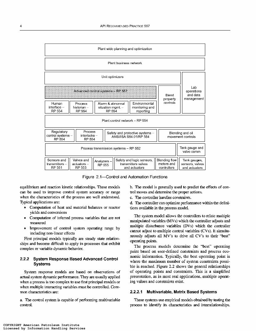
trol system applications and related systems. Figure 2.1 illus- trates basic control system functions and how they relate to this and other recommended practices.
2.1 REGULATORY CONTROL SYSTEM FUNCTIONS
Regulatory control systems provide fundamental control of process variables such as pressure, temperature, flow, and level by manipulating fìnal control elements such as control valves or electric motors. The standard control algorithm used in these systems is proportional-integral-derivative (PD), although alternate algorithms and calculations may also be used. The functions of regulatory control systems are covered in API RP 554.
Complex regulatory control systems typically combine a number of functions used in regulatory control systems to meet a control objective. Typical applications include:
Cascade control Dynamic compensation, e.g., filtering or time-shifting of variables Variable gain adaptive controllers or other non-linear
Calculated variables such as pressure and temperature compensation of flow or other simple computations Override control using output selectors Ratio controllers
The regulatory control system must be configured to allow remote access to its setpoints so the advanced control system can write to them. It must also have a mechanism to automat- ically disable these remote setpoints or go to a pre-deter- mined status if the advanced control system has failed.
algorithms
2.2 MODEL-BASED CONTROL SYSTEMS
Model-based control systems use a mathematical model of the process to improve process performance. The model may be based on process engineering principles or may be are described below.
2.2.1 First Principle Model-Based Advanced Control Systems
First principle models are derived from the fundamental mass and energy balances, and associated thermodynamics,
COPYRIGHT American Petroleum InstituteLicensed by Information Handling ServicesCOPYRIGHT American Petroleum InstituteLicensed by Information Handling Services
4 API RECOMMENDED PRACTICE 557
Plant wide planning and optimization
Plant business network
Unit optimizers
Plant control network - RP 554
I I
ANSVISA S84.01/RP 554 movement controls
Tank gauge and 1 valve comm Process transmission systems - RP 552
Figure 2.1-Control and Automation Functions
equilibrium and reaction kinetic relationships. These models can be used to improve control system accuracy or range when the characteristics of the process are well understood. Typical applications are:
Computation of heat and material balances or reactor yields and conversions Computation of inferred process variables that are not measured Improvement of control system operating range by including non-linear effects
First principal models typically are steady state relation- ships and become difficult to apply in processes that exhibit complex or variable dynamic behavior.
2.2.2 System Response Based Advanced Control Systems
System response models are based on observations of actual system dynamic performance. They are usually applied when a process is too complex to use first principal models or when multiple interacting variables must be controlled. Com- mon characteristics are:
a. The control system is capable of performing multivariable control.
b. The model is generally used to predict the effects of con- trol moves and determine the proper actions. c. The controller handles constraints. d. The controller can optimize performance within the defini- tions available in the process model.
The system model allows the controllers to relate multiple manipulated variables (h4Vs) which the controller adjusts and multiple disturbance variables (DVs) which the controller cannot adjust to multiple control variables (CVs). It simulta- neously adjusts all MV’s to drive all CV’s to their “best” operating points.
The process models determine the “best” operating point based on user-defined constraints and process eco- nomic information. Typically, the best operating point is where the maximum number of system constraints possi- ble is reached. Figure 2.2 shows the general relationships of operating points and constraints. This is a simplified presentation, as in most real applications, multiple operat- ing values and constraints exist.
2.2.2.1 Multivariable, Matrix Based Systems
These systems use empirical models obtained by testing the process to iden@ its characteristics and interrelationships.
COPYRIGHT American Petroleum InstituteLicensed by Information Handling ServicesCOPYRIGHT American Petroleum InstituteLicensed by Information Handling Services

GUIDE TO ADVANCED CONTROL SYSTEMS 5
Operating range wlo
r Cooling I constraint Operating raige WIO
advanced controls
Controlled variable
Figure 2.2-Operating Conditions versus Constraints
Matrix controllers use linear models to relate MVs and DVs to CVs. They may also incorporate transformations of inputs and outputs to handle process nonlinearities. Some versions of these controllers have been extended to use non-linear models. These controllers have been used in the refining industry for several years and have evolved considerably.
2.3 OPTIMIZERS
ûptimizers provide a computation method to determine the “best” operating point based on user-defined economic objec- tives and a model of the process. The outputs of optimizers are usually steady state objectives for other controllers such as multivariable controllers that handle dynamic control.
2.2.2.2 Neural Net Systems
Neural networks are capable of providing similar fmction- ality as matrix controllers. The fundamental difference between neural net and matrix controllers is a learning engine that develops the process model based on observations. The learning engine behaves somewhat like an optimizer that combines observations and user-supplied rules to generate a process model.
Neural net controllers require substantial historical data from which the model is created. If such data is not available, an extended data acquisition period may be required. In some applications step testing is done to “train” the neural net.
Neural net controllers can produce non-linear models and can adapt the model to process changes without requiring for- mal process testing. Typically, these adaptations are per- formed off-line using parameters generated by the on-line neural net application.
Neural net controllers are a recent development and do not yet have the same experience or success base as matnx-based controllers.
ûptimizers may operate in an off-line or on-line mode. In the off-line mode the model is not receiving dynamic data from the process. In the on-line mode key real-time process data is connected to the model.
An on-line mode application may be on-line open loop or on-line closed loop. In on-line closed-loop mode the outputs are automatically passed to the dynamic controls. In on-line open-loop mode, the optimizer outputs are presented to the operator, and the operator is responsible for passing changes to the dynamic control.
In on-line applications, significant data validation and rec- onciliation are necessary. It may also be necessary that steady operations exist when the optimizer is run. Some more pow- erfiil optimizers may not require this.
2.3.1 Imbedded Linear Programs
Many multi-variable controllers contain an imbedded lin- ear program to solve an optimization problem. The imbedded LPs are based on linear relationships between CVs and costs. Typically, these applications address a small number of pro- cess variables, usually less than 20 variables.
COPYRIGHT American Petroleum InstituteLicensed by Information Handling ServicesCOPYRIGHT American Petroleum InstituteLicensed by Information Handling Services

6 API RECOMMENDED PRACTICE 557
2.3.2 Unit Level On-Line Optimizers
Unit level optimizers may be used to compute operating targets for one or more unit multi-variable controllers. These optimizers typicaiiy use a much larger number of variables and may have thermodynamic, equilibrium or kinetic rela- tionships built into them. They usuaiiy require functions for data validation, reconciliation and parameter estimation. Unit level optimizers typicaiiy are able to access economic data from external sources. Unit optimizers may use more rigor- ous non-linear models to identify optimum operating condi- tions for the overall unit.
2.3.3 Plant Wide Optimizers
Linking several unit level optimizers allows the system to locate a global optimum for the entire plant. In practice this is an extremely complex undertaking. This type of optimization requires rigorous models to ensure accurate results. Data rec- onciliation with overd material balances and yield account- ing systems is a critical requirement for plant level optimizers. For example, as the product slate from one unit is the feed to the next, a smaii error introduced due to a poor model or conflicting data will propagate throughout the entire optimizer, which can provide an inferior result.
Use of these optimizers has often been limited by the accu- racy of the unit optimizers when applied to very large systems. The computing load for these optimizers and the volume of input data can be immense. Some success has been obtained using off-line linear program models of a number of plants.
2.4 EXPERT SYSTEMS
Rule based systems are used in refìnery applications where predetermined events exist. They are well suited for providing detailed information to operations based on events that have occurred in the process. Typically, these systems are used in an advisory capacity and are not directly connected to a con- trol system. Abnormal Situation Management is an emerging application of expert systems.
2.5 FUZZY LOGIC SYSTEMS
Fuzzy logic is used when the rules followed are inexact. It is a technique which can transform graded or qualified rules, such as if a “temperature gets too hot then slowly increase the cooling water”, into specific actions. Fuzzy controllers are a developing technology in the process industries. Fuzzy con- trollers may be imbedded in equipment controllers provided with packages. Some DCS systems provide fuzzy control blocks as part of their algorithm set.
2.6 BATCH AND SEQUENCE SYSTEMS
These control strategies are used for operations that have finite steps executed in a predetermined order. Examples are reformer regeneration, water treating, coke handling, etc. These operations are described in detail in ISA S88.01 and are not within the scope of this recommended practice.
2.7 BLENDING SYSTEMS
Component blending is used in various fuel production complexes. These systems are comprised of blend ratio regu- latory control elements, property estimators and optimizers that adjust recipes to meet final property specifications. The control systems used include advanced strategies as described in this document, but blending practices are not within the scope of this recommended practice.
2.8 OIL MOVEMENT SYSTEMS
oil movement systems use heuristic rule-based systems and are not within the scope of this recommended practice.
3 Opportunity Identification and Justification
3.1 RESOURCE REQUIREMENTS
The identification of improved control opportunities is a multi-disciplinary task with operations planning, operations, process and control application knowledge and experience playing the most significant roles. Refiners’ experiences have demonstrated that the essential element of success in imple- menting advanced control projects is the engineers’ knowl- edge, experience and ability. While appropriate technology is an important factor, it cannot make up for lack of skill or experience in the personnel implementing the application.
A benefits feasibility study for a single process advanced control application can be handled by a suitably skilled indi- vidual relying on specialist support where required. However, as the scope of the study increases, particularly when study- ing a complete refìnery, a small mixed discipline team approach is recommended. The team should include repre- sentation from site process/planning, operations and control system engineering.
Benefit identification requires both technical and inter-per- sonal communication skills. Identification and realization of benefits requires:
a. Understanding the economic driving forces for the processes. b. Understanding how the processes work and interact. c. Understanding the process’s real limitations and con- straints . d. Obtaining buy-in for the benefits and solutions from the advanced control users and support specialists.
3.2 THE ECONOMIC DRIVERS
Long and short-range business plans should be the basis for evaluating potential benefits. These plans must reflect the impact of a number of typical economic driv- ers. Not all of them will be applicable to a particular mar- ket or refinery, but they are indicative of the forces that
COPYRIGHT American Petroleum InstituteLicensed by Information Handling ServicesCOPYRIGHT American Petroleum InstituteLicensed by Information Handling Services

GUIDE TO ADVANCED CONTROL SYSTEMS 7
determine refining economics. Examples of economic drivers that must be considered are:
Business Management Drivers Financial objectives Environmental and safety objectives Process unit turnaround schedules
Local Plant Drivers Crude and other feed stocks and finished product pricing Volume and shipping methods for crude and other feed stock Demand and shipping method of finished products Product margins Utility usage and prices
Local Economy Issues Seasonal variations in product demand, quality and
The economy in which the plant operates, e.g., open or closed market economic operation Government influence and requirements
supply
3.3 IDENTIFICATION OF POTENTIAL APPLICATIONS
Most opportunities are identified during discussions with site personnel from the process, planning and operations functions and a preliminary assessment of the process perfor- mance data. The following are useful guidelines for this pre- liminary assessment:
a. Review actual plant performance against production/oper- ating targets. b. Review plant performance against best of class or other benchmarks. c. Review the economic drivers added value potentials. d. Consider any anticipated process plant changes. e. Ident@ improvements that have been realized by existing advanced control system applications. f. Ident@ opportunities for control improvements using rig- orous plant steady state models that have been tuned to correlate with actual plant data.
A number of improvement areas which may be considered are listed in Table 3.1.
The outcome of this preliminary assessment is a list of potential applications and their benefits. This list should be reviewed with appropriate personnel to rank the potential benefits and identify those which appear to have high poten- tial and which should be further studied.
3.4 IDENTIFICATION AND QUANTIFICATION OF BENEFITS-FEASIBILITY STUDY
Each of the top ranked items identified from examination of the potential benefits should be considered in detail. The
overall methodology is outlined in Table 3.2. For existing plants, data can be obtained based on observed operation. For new plants, these data could be obtained from assessment of equivalent data from similar operations or process models.
3.4.1 Application Objectives
The first step in the feasibility study is to identify the objectives of the proposed control application. This can be achieved though a series of discussions with the site represen- tatives from the planning, technical and operations functions. It is important that process constraints/iimits and production targets/specifications are examined and challenged. Identified constraints should be considered for testing and data collec- tion, as they may be perceived rather than real.
It is also important to iden@ the effects that proposed control improvements may have on other units or utilities. For example, an increase in an intermediate product stream rate may exceed the capabilities of downstream equipment. How- ever, the benefits of selling any excess intermediate should be considered.
3.4.2 Data Collection and Validation
3.4.2.1 Data Requirements
The objective of this step is to iden@ all the necessary data and information which will quan@ the actual perfor- mance of the process relative to its operating targets and the control objectives.
The following types of data should be collected in suffi- cient quantity to be statistically significant and consistent:
a. Operating targets-such as product qualities, rates, yields. b. Actual values achieved-feed and product rates, yields and laboratory and on-line analyzer results. c. Process operating constraints and limits, reasons and val- ues-this could include throughputs; pressure/ flow/ temperature limits, valve position and equipment capacity limits, limitations imposed by other processes or planning restrictions, environmental restrictions or safety restrictions. d. Availability of process (stream days) and reasons for out- ages or restricted operation. e. Measurement availability- analyzers, flows, etc., includ- ing accuracy, repeatability and reliability. f. Discrete events such as coke drum sequencing, dryer switches, etc. g. Control system performance indicators such as poorly per- forming control loops, control valves, etc. h. Future plans and timing for process modifications and their potential impact. i. Production operating target changes which may be planned. j. Future operational flexibility requirements. k. Economic driver data and long-term plan. See Section 3.2.
COPYRIGHT American Petroleum InstituteLicensed by Information Handling ServicesCOPYRIGHT American Petroleum InstituteLicensed by Information Handling Services

8 API RECOMMENDED PRACTICE 557
Improvement Area
Yield
Stability
Throughput
Reactors
Energy Usage
Heaters
Miscellaneous
Table 3.1-Advanced Control Benefits
Potential Benefits
Product upgrading Reduced variability Reduced quality give-away on intermediate or final product 2ontrol closer to targets
Reduced product downgrading Reduced energy usage Production closer to constraints for better control
Higher production by better operation against process equipment constraints and limits such as: rray vaporhquid loading 2ondensedreboiler duty Pump/control valve capacity Heater/vessel temperatures Pressures/flowsilevels 2ompressor parameters Minimization of unwanted material in feedstock (i.e. nC4 in alkylation feed)
improved reactor performance by better control of: Weighted average inlet temperature Weighted average bed temperature Hydrogen to feedrecycle Reactant and other key process variables
Reduce total energy costs by better control of: Reflux ratios Pressure minimization, Reduced stripping steam Pumparound heat recovery
Improved efficiency of heater operation through: Swing fuel firing control to maximize usage of lower value or variable fuel Injection steam ratio control where appropriate Multi-user control strategy @.e., Hot Oil Systems) Pass outlet temperature balance control
Enhanced understanding of the process for better management of all site functions improved equipment reliability due to more stable operation at intended conditions Sharing of best practices from other applications
Assumptions will have to be made where necessary data and information are unavailable. Assumptions relative to missing data and the impact on the confidence of eco- nomic predictions should be discussed with and accepted by site personnel.
3.4.2.2 Representative Period of Operation
It is important that one or more representative periods of operation be selected and agreed on as the basis for benefit identification. These should reflect ‘normal’ operation of the process-no shutdowns, processing deficiencies nor unusual planning/production requirements. Any variation due to weather or day/night operation should be included. One month minimum is recommended, particularly when infre- quent (once per day) laboratory data will be used in the analy- sis. The data analyzed must be statistically significant and consistent.
Data from several periods during the operational run of a unit may be required. This will account for effects such as seasonal changes to plans and targets, ambient conditions or start-of-run to end-of-run conditions that may have a signifi- cant impact on potential benefits.
The representative period(s) will be used for pro-rating the potential benefit to an annual basis using an agreed on stream days per year. Stream days vary between processes and sites. Three-hundred-and-fifty stream days per year are often used as a default when no specific information is available.
Failure to identify and agree on realistic representative periods can lead to misleading and erroneous benefit pre- dictions. For example, the actual and audited benefits of a crude unit application were $900,000 for the summer months and only $100,000 for the winter months. The original feasibility study had been based on summer oper- ation only ($1.8MM/year). Benefits were therefore over- predicted by $800,000 per year.
COPYRIGHT American Petroleum InstituteLicensed by Information Handling ServicesCOPYRIGHT American Petroleum InstituteLicensed by Information Handling Services

GUIDE TO ADVANCED CONTROL SYSTEMS 9
Table 3.2-Benefit Feasibility Study Steps
1. Identify application objectives . 2. Identify representative period of operation.
I 3. Collect and validate process data . I I 4. ~nalyze data for performance against targets. I I 5. Identify control application improvement. I
6. Analyze control infrastructure performance and requirements. 7. Apply appropriate economics.
8. Categorize benefits on a confidence basis. I 9. Review and agree benefits analysis with site. I I 10. Set-up post-application benefit audit basis. I 3.4.2.3 Performance Data Validation
Collected data must be validated before it is used in benefits computations. Typical steps taken to validate the data include:
a. Filter out any obvious bad process data, including data from identified ‘non-normal’ operation in the representative period( s) . b. Carry out a simple statistical mean and standard deviation analysis of the absolute actual values of targets and con- straints as appropriate. c. Compare to site-wide data reconciliation.
Note: Frequently the statistics vary as a function of the targets set and often reflect the non-linear response of the process. In these cases, it is more meaningful to perform the statistical average and standard deviation on the difference between the target and actual values and to calculate a time weighted average for the actual value.
3.4.3 Control Improvement Prediction
3.4.3.1 Analysis Techniques
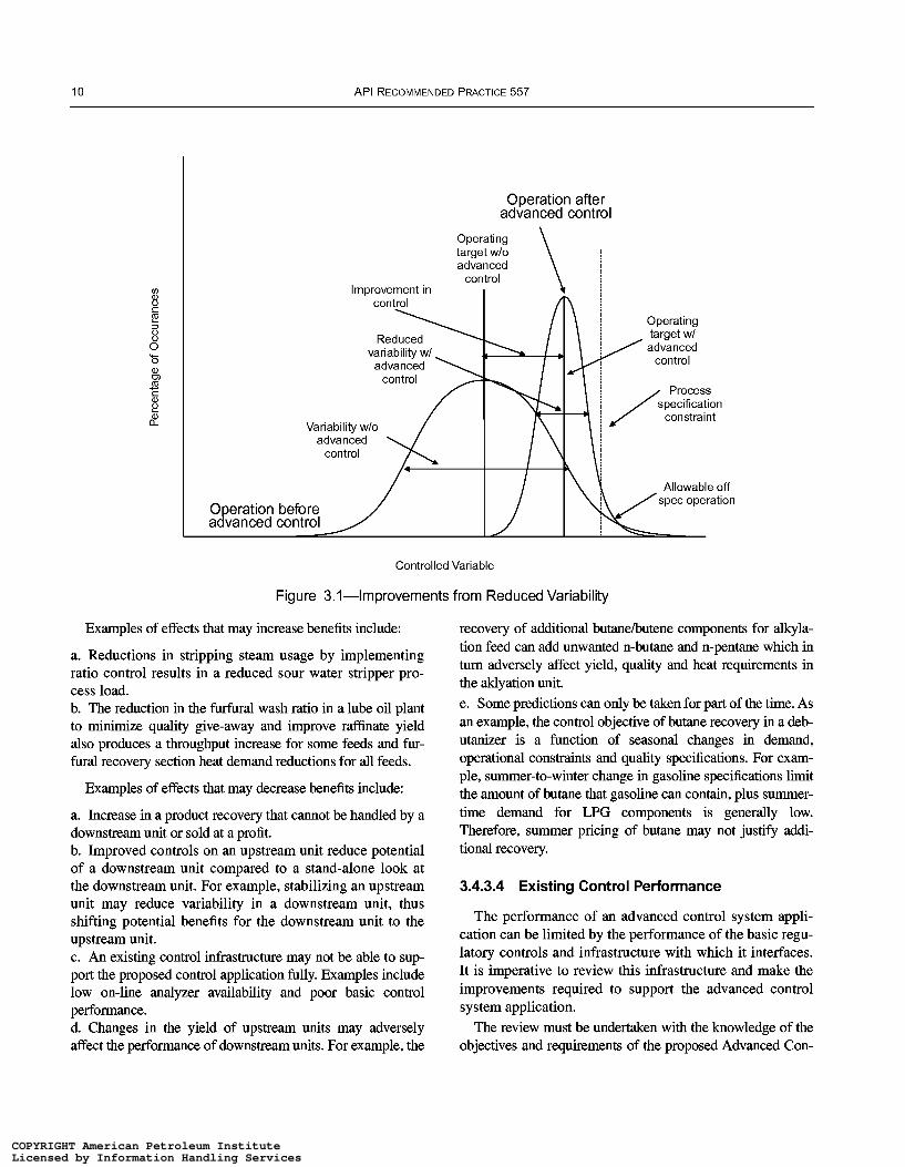
An important method in analyzing potential control improvement benefits is statistical analysis. Reducing the standard deviation of controlled variables (targets, set- points) and moving operation closer to constraints is well accepted in practice as a basis for predicting the improve- ment achievable. Often a 50% reduction is assumed, but the current value of the standard deviation should be con- sidered and evaluated before assuming a reduction. Often, a 50% reduction, can be somewhat conservative as shown by actual audits of control applications.
It should also be noted that the improvement in stability of the controlled variables is often achieved by more frequent adjustments of the manipulated variables. However, the net effect is a reduction in variability of the controlled variables. Figure 3.1 illustrates how reduction in variability results in the ability to operate closer to process constraints, which gen- erally translates into tangible benefits related to increased
process rates, improved product quality, reduced giveaway or similar economic benefits.
Another valuable analysis is to compare operations vari- ability among operating crews. Often significant benefits can be quantified by comparing “best” operation vs. average operation within the site.
Skill is required in selecting which prediction method to employ. Limitations in information or current capability may indicate one method when in fact another is more appropriate. As discussed above, it is also necessary to consider the time weighted average of control targets when those targets are changing.
The prediction of reduced variability may then affect the overall process yield, feed rate or energy usage. Economic factors for these effects should be readily available from the site. The same data can be obtained from a rigorous steady state process model and appropriate pricing information. Such a model can also be used to assess the impact of the pre- dicted change(s) on other process parameters to confìrm that the change is realistic and viable with respect to known pro- cess operating limits/constraints.
Where no acceptable analysis technique exists, it may be possible to infer benefit information from similar applications. However, this will impact on the confidence of the prediction.
3.4.3.2 Practical Considerations
One hundred percent of an identified benefit is rarely achievable in practice. Perfect control is not possible and some small, but positive, give-away will generally be required to ensure that market product specifications are not exceeded.
The existing control performance affects both the benefits prediction and the ability to realize the benefit with the intended control application. Additional measurement and control capabilities may be required and their availability and utilization affect the realizable benefit. The use of on-line analyzers, either physical or inferential, may be required to realize a significant part of the benefit. Analyzer availability must be pro-rated into the prediction.
Process constraints and plant limitations provide limits to a benefit. However, actual constraints or limits should be estab- lished on an objective basis as limits may be more perceived than real or could be relaxed by improved control or minor physical modification.
Significant product yield pattern changes are often a result of these evaluations. However, the prediction must reflect the present and future market situation. Predicted benefits will have to show up in the bottom line of the site’s operation.
3.4.3.3 Synergystic Effects
The realization of a predicted benefit can have synergys- tic effects. These can either increase or decrease the ulti- mate benefits.
COPYRIGHT American Petroleum InstituteLicensed by Information Handling ServicesCOPYRIGHT American Petroleum InstituteLicensed by Information Handling Services
10 API RECOMMENDED PRACTICE 557
Operation after advanced control
Controlled Variable
Figure 3.1-Improvements from Reduced Variability
Examples of effects that may increase benefits include:
a. Reductions in stripping steam usage by implementing ratio control results in a reduced sour water stripper pro- cess load. b. The reduction in the furfural wash ratio in a lube oil plant to minimize quality give-away and improve raffìnate yield also produces a throughput increase for some feeds and fur- fural recovery section heat demand reductions for all feeds.
Examples of effects that may decrease benefits include:
a. Increase in a product recovery that cannot be handled by a downstream unit or sold at a profit. b. Improved controls on an upstream unit reduce potential of a downstream unit compared to a stand-alone look at the downstream unit. For example, stabilizing an upstream unit may reduce variability in a downstream unit, thus shifting potential benefits for the downstream unit to the upstream unit. c. An existing control infrastructure may not be able to sup- port the proposed control application fully. Examples include low on-line analyzer availability and poor basic control performance. d. Changes in the yield of upstream units may adversely affect the performance of downstream units. For example, the
recovery of additional butanebutene components for *la- tion feed can add unwanted n-butane and n-pentane which in turn adversely affect yield, quality and heat requirements in the aklyation unit. e. Some predictions can only be taken for part of the time. As an example, the control objective of butane recovery in a deb- utanizer is a function of seasonal changes in demand, operational constraints and quality specifications. For exam- ple, summer-to-winter change in gasoline specifications limit the amount of butane that gasoline can contain, plus summer- time demand for LPG components is generally low. Therefore, summer pricing of butane may not justify addi- tional recovery.
3.4.3.4 Existing Control Performance
The performance of an advanced control system appli- cation can be limited by the performance of the basic regu- latory controls and infrastructure with which it interfaces. It is imperative to review this infrastructure and make the improvements required to support the advanced control system application.
The review must be undertaken with the knowledge of the objectives and requirements of the proposed Advanced Con-
COPYRIGHT American Petroleum InstituteLicensed by Information Handling ServicesCOPYRIGHT American Petroleum InstituteLicensed by Information Handling Services

GUIDE TO ADVANCED CONTROL SYSTEMS 11
trol System Applications. Examples of the areas which should be addressed include:
a. On-line analyzers-current performance and availabil- ity -Is improvement required? What additional analyzers or analyzer modifications are required? b. Regulatory controls -current performance- Are modi- fications or loop tuning required? Is a major upgrade prerequisite to implementation of the advanced control applications? c. Control facilities maintenance-Is field equipment reli- ability high enough to support an Advanced Control System Application? d. Control valve performance problems-Are valves appro- priate to the service or are improvements in valve dynamics or precision required? e. Additional required measurements- Are additional flow, column dBerential pressures, levels, etc. measurements needed to support the advanced control applications? f. Are inferential models required because analyzers are not reusable or because the cycle time is long or results are not frequent enough for the control. g. New or upgraded control facilities-Often existing regulatory control schemes must be improved or modi- fied. Occasionally equipment cannot be operated in the manner intended and the control objectives must be modi- fied. Examples are:
- Heaters-A control objective may be to improve efficiency by air trim control, but the basic require- ments of box pressure and emissions compliance must also be met.
- Local Controllers-Many sidestream strippers have local pneumatic level controllers with perhaps an indication in the control room. Often the level con- trol valve position is identified as a constraint. This requires relocating the controller to the DCS or mak- ing the control valve position available to the advanced control system.
- Measurements/Control Loops - Stability improve- ment may require upgrade of existing regulatory controls. For example, existing level and tempera- ture control loops may need to be modified to include cascade flow control. New measurements may be necessary for identified constraints. Often, side streams are not flow controlled, but the advanced control scheme may require it. In this instance a flow measurement element and flow con- troller may need to be added.
- Pre-Control Project Improvements -The feasibly study invariably results in identification of any num- ber of improvements. For example, loop tuning, con- trol valve sizing and performance, improved sensors, etc., can be made without implementing the advanced control application. The benefits of these
improvements may reduce the increment benefits attributable to the advanced control application.
3.4.4 Economic Prediction
The final economic benefits predictions require combining the identified control improvements and operating economics discussed above.
Where possible the predicted benefits should be con- firmed against production performance monitoring. For example, performance monitoring should indicate similar magnitudes from assessment of product give-away or loss. Where available plant wide LP models can also help back check predicted benefits.
3.4.5 Benefits Assessment
Predicted benefits should be assessed to identify probabili- ties of realizing the benefits. Idenming benefits in terms of confidence can be very helpful in supporting financial cases for applications and quanming of economic risk. Generally, benefits fall into three areas:
a. Benefits which can be rigorously quantified. b. Benefits which can be positively identified in a qualitative sense but less rigorously quantified. c. Benefits which are less tangible. These benefits cannot be readily quantified, but are generally recognized in the indus- try. The quantification of these benefits may be somewhat subjective. These benefits tend to be those derived from the improved knowledge of the process, better operator inter- faces, improved efficiencies such as better operator utilization, reduced maintenance and faster troubleshooting.
3.4.6 Benefits ReportinglFunctional Specification
An advanced control feasibility report should be prepared. This document should address the following items:
a. An overview of the process. b. Current and future operating objectives. c. Economics used for the benefits prediction. d. Benefits prediction analysis, including assumptions made and references to all data sources. e. Functional specification and scope definition of application:
- Description of control objectives. - List of control UO. - Implementation platform requirements. - List controllmeasurement upgrades required. - Control infrastructure upgrade requirements.
f. Preliminary estimates of implementation costs, including the following:
- Application hardware and software including licence fees.
- Engineering and project management.
COPYRIGHT American Petroleum InstituteLicensed by Information Handling ServicesCOPYRIGHT American Petroleum InstituteLicensed by Information Handling Services

12 API RECOMMENDED PRACTICE 557
- Owners costs, support, training, documentation. - Measurement additions and upgrades. - Regulatory control upgrades. - Contract services. - Travel and living expenses.
g. Preliminary schedule. h. Plans for post application audit.
3.4.7 Benefit Post-Application Audit Planning
Experience has demonstrated that post-implementation audits are only as good as the quality of the pre-implementa- tion (base case) information. The base case must be devel- oped prior to implementation as this is the only time that the correct base data exists.
The information and data produced for a benefits predic- tion study provides a very sound basis (base case) for car- rying out a subsequent post-application audit. The application implementation will always be in the future. Hence, it is important that the impact of any intervening changes, both non control (process modifications, catalyst/ target changes etc.) and control are evaluated to check the validity of the base case.
4 Advanced Control Projects This section addresses aspects of project management
and execution that are unique to advanced control projects. This section is not intended to describe general project execution issues such as budget, schedule and contracting, but is intended to address those issues unique to advanced control projects.
An advanced control project may consist of implemen- tation of one or more applications. The scope may also include infrastructure scope items such as field instrumen- tation and measurements, and regulatory control enhance- ments in addition to the applications and their associated hardware and software.
4.1 MASTER PLAN
Prior to embarking on any advanced control projects, the facility should have a defined Master Plan for Automation. This plan should have the full support of facility management and have considered the strategic business impacts. The con- tent of an automation master plan will vary from facility to facility, but should contain the following elements:
a. Definition of the long-term objective of the master plan and division of the work into phases. b. Identification of benefits to be realized from each phase of the plan. c. Definition of the control and computing equipment and software platforms that the facility will use. This may include definition of dowed applications for various hardware and software alternatives.
d. Identification of existing and planned control networks and an expansion path or evolution plan for those networks. e. Definition of process control implementation standards and practices for the facility. f. Identification of critical timing issues with respect to unit turnarounds or other shutdowns that may be opportunities for control and instrumentation system modifications, upgrades or improvements. g. Milestones or schedule for review and update of the plan. h. Identification of resources required to provide ongoing application maintenance after implementation is complete.
4.2 PROJECT EXECUTION PLAN
Prior to commencement of an advanced control project, a project execution plan should be prepared as a guide to how the objectives of an advanced control project will be realized. The plan should build on the information in the feasibility report and master plan. It should address the following:
4.3
Timing of the project Functional specification Resource requirements Project benefits Benefit validation plan Training plan Design plant testing and implementation plan Commissioning plan Post commissioning economic performance plan Ongoing application support and maintenance
IMPLEMENTATION ISSUES
Advanced control projects have a number of implementa- tion issues that are not normally associated with projects of other types. The project engineer should be fully cognizant of the requirements of the facility master plan and be prepared to execute the project within the guidelines of this plan
Common issues associated with implementation of advanced control applications are:
a. Advanced control projects often involve upgrades of exist- ing control systems. This may range from wholesale upgrades of obsolete instrumentation systems with modern DCS sys- tems to incremental upgrades of existing systems. b. Most advanced control projects will involve addition or upgrade of process measurements. Some of these measure- ments may not be accessible during normal operation and design of the control system may have to recognize delayed availability of certain measurements. Some of these measure- ments may involve the use of on-line analyzers. Typically analyzers must be installed and have a demonstrated perfor- mance history before the advanced control application can use the measurement. The project budget and schedule must recognize the costs and timing associated with new or upgraded measurements.
COPYRIGHT American Petroleum InstituteLicensed by Information Handling ServicesCOPYRIGHT American Petroleum InstituteLicensed by Information Handling Services

GUIDE TO ADVANCED CONTROL SYSTEMS 13
c. New construction projects often involve implementation of an advanced control system. Usually this implementation cannot proceed to any extent until after the construction has been completed and operating data are available. d. New construction projects may also involve modification of existing units, which may also have existing advanced con- trol systems. The scope of new construction may be such that the process equipment, operating conditions or operating characteristics will be different than those on which the exist- ing advanced control system was based. This may require that the existing advanced control system be redesigned or modi- fied before it can be recommissioned. e. Many advanced control projects are dependent on having a unit shutdown to install measurements that may not be acces- sible during operation. Until these measurements are available, it may not be possible to completely perform pro- cess testing or control system implementation tasks. This shutdown may also be required to implement control system replacements or upgrades. Many times the turnaround or shutdown schedule will determine the overall advanced con- trol project schedule. f. Process safety management regulations usually require that process hazard analysis be performed on the advanced control system. This may require implementation of a management of change procedure to assure that develop- ments in system design are properly reviewed before they are implemented. g. An advanced control system’s design may be based on a number of different techniques. Among these are steady state and dynamic process modeling to iden@ relationships among key operating variables and on stream testing of exist- ing systems to derive empirical relationships. If significant process modifications are being made in parallel with the advanced control project, some of this work may not be com- pleted until the modifications have been completed. h. An advanced control system project may require integra- tion of multiple software packages, possibly from more than one supplier. An integration plan, including identification of the organization and individuals responsible for ensuring that all software works as intended. The use of a single “suite” of software versus several applications from different sources should be evaluated. Not all applications in a suite of software may be the best fit for a project, but this should be weighed against the cost of implementing and maintaining software integration among several vendor’s offerings.
4.4 PERSONNEL COMMITMENTS
Successful execution of an advanced control project requires commitment of an appropriate number of personnel with the appropriate skill sets. As mentioned above, availabil- ity of personnel with the knowledge, experience and ability to undertake advanced control projects is critical to the success
of the project. Attempting to implement a project without adequately skilled personnel will likely result in failure.
As compared to many other types of desigdconstruction projects, advanced control projects require that a substantially higher percentage of total project costs be devoted to engi- neering. Advanced control applications also require contin- ued maintenance if a continuous benefit stream is to be realized. Process facility management must recognize the personnel commitments required and consider them with respect to benefits when making staffing decisions.
4.4.1 General Skill Set
Personnel assigned to advanced control projects should be familiar with the specific practices and techniques associated with such projects. This includes knowledge and experience in process control engineering, control system hardware and software and general process engineering.
4.4.2 Project Management Skills
Project management skills are an important factor in advanced control project execution. However, the manage- ment methodology must recognize the unique characteris- tics of advanced control projects. This includes issues such as critical path schedule items often being unit shutdown driven, extended periods where little or no apparent progress is made due to these restrictions, and the often extended implementation, testing and validation periods associated with such projects.
4.4.3 Specialist Support
Participation of specialists skilled in such areas as process engineering, computer implementation or analytical methods is a critical component of an advanced control project. These individuals may be on the owner’s staff or may be contract or manufacturer/vendor employees. In any case, these individu- als may need to devote a significant amount of time to the effort.
4.4.4 Vendor or Consultant Support
In many cases, an owner may not have sufficient staff with the requisite skills available. In these cases, use of manufacturer, vendor or consultant personnel can be applied to leverage existing staff and realize the benefits of the applications. Should use of such personnel be neces- sary, the owner should ensure that the personnel have the requisite skills and training.
4.4.5 Plant Operations and Maintenance Support
A key component of any successful advanced control project is the support and participation of plant operations and maintenance personnel. Operations input is a key factor in
COPYRIGHT American Petroleum InstituteLicensed by Information Handling ServicesCOPYRIGHT American Petroleum InstituteLicensed by Information Handling Services

14 API RECOMMENDED PRACTICE 557
Task
Facility Master Automation Plan
defining advanced control objectives and strategies and in 4.5 SCHEDULE
Typical Timing
12 to 60 months prior to project initiation
implementation, execution and maintenance of the control scheme, operator interfaces and backup and fallback strate- gies. It is highly recommended that a skilled operator be assigned to the project team.
Maintenance input is necessary to identify requirements for the advanced control system to handle routine or unscheduled maintenance of sensors, transmitters, control elements and control equipment and engineering oriented changes such as loop tuning, configuration changes, etc. These issues must be addressed as an integral part of the advanced control system design.
Regulatory Control and Measurement Design
Design Specification
Advanced control projects have scheduling characteristics that are unique to these types of projects. These characteris- tics often result in high activity periods separated by substan- tial periods of little or no apparent activity.
Prior to starting an advanced control project, all significant tasks and their expected duration must be deñned. All sched- ule constraints imposed by resource availability and opera- tions should be identified. Table 4.1 shows a list of typical tasks associated with an advanced control project. The actual tasks, duration and lead time may vary substantially depend- ing on the scope of the application, plant operations and the prior experience of the engineering, operations and mainte- nance staff.
6- 12 months prior toprior to commissioning
With Regulatory Control and Measurement Design
Model Identification and Implementation
Engineer Training
Operator and Engineering Graphics Implementation
Advanced Control Hardware and Software Installation
I Feasibility Study and Project Identification I 6 to 18 months prior to project initiation
2-4 months prior to commissioning
Initial at software purchase. General training 4-6 months prior to commissioning
2-4 months prior to commissioning
2-4 months prior to commissioning
I Project Implementation plan I At initiation of project
Operator and Maintenance Training
Commissioning
Initial Advanced Control System Operation
Full Time Advanced Control System Operation
Close-out Documentation
I Functional Specification I Start of project scope definition
1 month prior to commissioning and during commissioning
1 to 2 months-Subject to operations schedule-reference point for other tasks
Commissioning and 2-4 months after commissioning
2-4 months after commissioning
1-4 months after commissioning
I Advanced Control Software Purchase I 6- 12 months prior to commissioning
I Hardware Platform Purchase I 6- 12 months prior to commissioning
I Model Identification Testing I 3-6 months prior to commissioning
Regulatory Control and Measurement Installation As allowed by operation and scope of design. Minimum 2-4 months prior to commissioning
I Install, Test and Simulate Advanced Control Applications I 2-4 months prior to commissioning
I Post Commissioning Economics Audit I 3-6 months after commissioning
I Advanced Control System Adjustments and Modifications I 2-6 months after commissioning
I Life Cycle support I Ongoing
Note: These tasks are generalized and not all tasks may be applicable to all types of control technologies. Depending on the technology used, additional or modified tasks may be necessary.
COPYRIGHT American Petroleum InstituteLicensed by Information Handling ServicesCOPYRIGHT American Petroleum InstituteLicensed by Information Handling Services

GUIDE TO ADVANCED CONTROL SYSTEMS 15
4.5.1 Re so u rce Avai lab i I ity
Personnel with the skills required for implementation of an advanced control project are in limited availability. As part of the scheduling process, the types of skills and number of per- sonnel required must be defined. The availability of such per- sonnel may determine the project schedule.
4.5.2 Impact of Ongoing Operations
Implementation of advanced control projects is often dependent on ongoing operations. Shutdowns or turnarounds may be required to add or modi3 process measurements or final control elements.
Process testing to develop process models or other relation- ships is usually required for any advanced control system. This testing often can consume several weeks and may be interrupted by unstable operations or operations at conditions different than those contemplated by the advanced control system. It is also not unusual that after initial process testing is completed, changes in operating conditions or objectives require additional testing.
4.5.3 Training
Training programs for operations, engineering and mainte- nance personnel must be developed. Depending on the responsibilities and prior knowledge of the personnel to be trained, the content and timing of this training will vary. Table 5.1 shows an example of an overall training program.
The training program must address initial training, refresher training for existing personnel, training for new per- sonnel and training in operations without the advanced con- trol application in service. The training program should have provisions for tracking an individual’s training history. Based on local regulations, it may be necessary that operators be certified to operate the process and its control systems.
4.5.3.1 Training Tools
At a minimum, training manuals shall be prepared for operator and maintenance technician training. The manual should describe:
a. The application and its implementation. b. All operator interfaces and reports. c. A list of inputs and outputs associated with the application and any requirements for their maintenance. d. Instructions on how to put the application on control and take it off of control. e. Operations in degraded control modes-e.g., partial shed- ding, operation with substituted values, etc. f. Application maintenance requirements and procedures.
Initial classroom training can familiarize the operators with the general application. This formal training must be supple- mented with on-console training and support by the advanced
control application engineers during initial testing and com- missioning. This training may occur over several weeks. The training plan should include plans for on-process training of shift operators and post commissioning training to update personnel on changes that were made during commissioning.
In the event that the advanced controls are not operating, the unit operator must be able to assume safe control of the unit. The effectiveness and reliability of modern DCS and advanced control systems has resulted in much more stable operation of process units. As a result, operators have far less exposure to upset operation, or operation without the advanced control applications running. Additional training is required to assure that the operators are capable of handling upset and degraded control conditions.
Process simulators are an effective means to provide this training. The advances in computer technology have made implementation of high fidelity dynamic simulators an effec- tive and economical tool for training. These simulators can accurately represent the behavior of a process, its control sys- tems and the operator interface. Routine refresher training of operators using dynamic simulators is becoming a viable and effective means of maintaining operator skills.
4.5.4 Testing and Commissioning
Relative to many other types of projects, the testing and commissioning processes for an advanced control systems are extended activities. Advanced control systems are usu- ally complex and require that a large number of variables and possibly several different operating conditions be tested and monitored.
Testing for an advanced control application consists of off- line or simulated operation during which the performance of the application is checked for correct operation. Some of the test objectives are to:
a. Ve@ input and output connections. b. Ve@ bad value behavior and control application shed- ding and degradation performance. c. Ve@ watchdog timer function for communication and application program failure. d. Ve@ that intermediate calculations produce expected results. e. Ve@ that application predictions and control outputs are as expected. f. Develop preliminary tuning. g. Exercise all operator, engineering and maintenance interfaces.
Commissioning consists of placing the application on pro- cess and observing and adjusting its performance for a long enough period to demonstrate acceptable operation.
Often initial commissioning is done on a limited basis with the advanced control scheme being operated during day shifts or when a key operating crew is on shift. During
COPYRIGHT American Petroleum InstituteLicensed by Information Handling ServicesCOPYRIGHT American Petroleum InstituteLicensed by Information Handling Services

16 API RECOMMENDED PRACTICE 557
Engineering
Table 4.2-Advanced Control System Training Program
Other Operators Operation w-wlo On-site Prior to commission- Classroom, on con- Controls ing and continuation sole & simulator
during commission- ing
sion tions and objectives "g Operation Supervi- Overview of func- Office Prior to commission- Presentation
Control Engineer Objectives, Process, Vendor facility & Prior to project and Classroom, simulator Control Technolo- office during functional gies and Detailed design Application
Organization
Operations
Maintenance
Personnel
Console Operator1 Liaison with APC project
Process Engineer Objectives, Applica- Vendor facility or Prior to commission- Presentation and tion Details, Com- plant training facility ing Classroom missioning, Operation w-wlo Controls
Scope Project Engineer Objectives and Office At start of project Presentation
Application Support Control Technolo- Plant training facili- During design Classroom, simula- Specialist gies and Detailed ties tor, actual system
Application Mainte- nance
Content
Detailed Commis- sioning, Operation w-wlo Controls
Location
Vendor facility or plant training facility
Timing
At functional design wl continuation dur- ing implementation and at commission- ing
Method
Classroom, detailed simulators, on pro- cess
I on-site Instrument and DCS Maintenance Proce- Technicians I dures w-wlo Con-
I Prior to commission- ing and continuation during commission- ing
Classroom, on pro- cess
this period, substantial specialist support is necessary to monitor the control system performance and identify any necessary modifications to the application. Larger applica- tions, or applications which are difficult to turn on and off may require that the control application operate around the clock and that commissioning application support also be available around the clock.
4.5.5 Economic Performance Audit
Prior to close out of an advanced control project, an eco- nomic performance audit of the advanced control system should be performed. This audit serves to validate the ben- efits identified during project development and provides the base line for use in monitoring ongoing performance. The methods used in performing this audit should be the same as those described above under Identification and Quantification of Benefits.
4.6 APPLICATION DOCUMENTATION
Each advanced control project shall produce a complete and accurate set of documentation for turn over to the plant
operations, maintenance and engineering groups. A docu- mentation package should be produced for each application. This documentation package typically contains items described below.
In addition to these documents, there will be a number of project oriented documents that may be retained in historical files. Some of these items are records of feasibility studies, scope definitions and estimates, project execution records and other records that are not identified as being required for turn over. Description of these files is not part of this scope.
4.6.1 Functional Specification
A functional specification for the advanced control appli- cation should be prepared and maintained during implemen- tation. This specification will be an update of the specification developed for the feasibility study.
4.6.2 Design Specification
The design specification addresses detailed require- ments to implement the application described in the func-
COPYRIGHT American Petroleum InstituteLicensed by Information Handling ServicesCOPYRIGHT American Petroleum InstituteLicensed by Information Handling Services
GUIDE TO ADVANCED CONTROL SYSTEMS 17
tional specification. Examples of the items that this document addresses are:
a. Description of the application objectives and functions. b. Definition of control technology and communications methods. c. Scope of DCS, regulatory control and measurement improvements. d. U 0 requirements. e. Model details.
- Expected M v s , CVs, and DVs. - Estimated response time for each controller.
f. Operator, engineer and maintenance interfaces. g. Requirements for turning the application on and off, and shedding or control degradation behaviors. h. Data base contents and structure. i. Maintenance requirements. j. Training requirements.
sidered while developing this specification. Section 6 describes a number of issues that should be con-
4.6.3 Ongoing Documentation
installation in the field and shall be kept current. The following types of documents represent the actual
4.6.3.1 Applications Configuration Data Base
A description of the contents and structure of the applica- tions configuration data base shall be maintained. Backup copies of the data base shall be made at regular intervals.
4.6.3.2 Graphics and Reports
The primary documentation for graphics is a hard copy of each graphic in the system, preferably in color, and a listing of code or configuration associated with the behaviors of all active graphic elements. Similar information shall be docu- mented for all configured reports. Electronic backups of all graphics and report fìles shall be made at regular intervals.
4.6.3.3 Program Listings
Up-to-date listings of all application programs should be kept in backed up electronic form, and if desired, in hard copy. It is also suggested that the listings be accom- panied by descriptive material defining the purpose and function of all programs and the inputs and outputs used by the application. Program flow diagrams should be included where appropriate.
4.6.3.4 Training Documents and Procedures
be maintained. Copies of training procedures, records and manuals shall
4.6.3.5 Maintenance Procedures
shall be maintained. Copies of maintenance procedures, records and manuals
5 Technology Considerations 5.1 HARDWARE PLATFORM
The hardware platform used for an advanced control appli- cation usually has a fundamental impact on the feasibility, economics, and the ultimate success of the application. The available options should be evaluated, and a choice of plat- form should be made, as early in the implementation as prac- ticable. Often, this may have been determined during development of the master plan. Control engineers and com- puter hardware systems specialists should be consulted when making this choice.
If the application software can run on multiple platforms, the relative advantages and disadvantages of each should be studied carefully. Typically, the choice will be between run- ning the application on standard distributed control system @CS) equipment or on general-purpose computer hardware. If the application is run on general-purpose computer hard- ware, often the choice will be between a workstation and a personal computer (PC) type platform. As DCS equipment migrates toward using more general-purpose hardware, and as PCs and workstations evolve to have similar capabilities and pricing, the distinctions between hardware platforms are becoming increasingly difficult to discern.
There are trade-offs between locating applications on DCS platforms versus general-purpose computers. For example, running an application on DCS equipment may have the advantages of close coupling to the underlying regulatory controls, use of the familiar DCS operator inter- face console, and for many applications, may require no new hardware. Disadvantages may be lack of portability of the application to other systems, less “friendly” implemen- tation and maintenance tools, and if required, hardware that is more expensive.
System security and maintainability are major consider- ations. Any computer running an advanced control system should be dedicated to advanced control functions and not be shared with non-related functions. It generally is permissible to run advanced control applications on the same computer that is running a historian, but should not be shared with applications such as accounting, personal computing servers or similar applications. It is good practice to segregate appli- cations so that loss of a single computer will have limited impact. Consideration must also be given to computer load- ing so that applications will execute in the time required.
The recent history and likely future for a hardware plat- form should be analyzed carefully against the require- ments for the application. The computer hardware and operating system environment is volatile and consideration
COPYRIGHT American Petroleum InstituteLicensed by Information Handling ServicesCOPYRIGHT American Petroleum InstituteLicensed by Information Handling Services

18 API RECOMMENDED PRACTICE 557
should be given to migration paths available. The condi- tions and the hardware support infrastructure at the site should be evaluated carefully. This is especially true if the hardware platform will be completely new to the plant site requiring additional training or new support personnel. Contract hardware support with the hardware vendor may be an attractive alternative.
Involving knowledgeable specialists from diverse back- grounds often can prove beneficial in hardware selection. The capabilities of general-purpose computer hardware and DCS systems are continuously changing. Proper selec- tion of hardware requires the input of specialists who are aware of the existing and developing capabilities of vari- ous hardware platforms.
often the advanced control application supplier, the under- lying DCS hardware restrictions, or a previous choice of user company standard hardware may dictate the choice of hard- ware. Such a dictated choice should be evaluated to assure that the selection is appropriate.
5.2 SOFMIARE PLATFORM
The software platform consists of the operating system, the control application development package, and data collec- tiodarchiving packages with associated database systems. Issues which should be considered when selecting a software platform are discussed below.
5.2.1 Data Flow
Data flow requirements for control applications can have a major inñuence on the selection of a software (and hardware) platform. The data flow requirements of each control applica- tion should be analyzed when choosing the software plat- form. The real time aspects of control applications require that data flow in a deterministic manner at regular intervals, and that this data come from or go to a permanently assigned location. Some software platforms can present a major prob- lem for some control applications, for example:
a. The platform depends on exception-based data reporting. b. The platform uses relational database structures. c. The platform cannot process data frequently enough.
Control engineers familiar with the dynamic data require- ments of the control application should be involved in data flow evaluations.
5.2.2 Application Separation
Individual control applications running on a common software platform shall be separate and distinct from each other. Any control application shall not depend on any part of any other unrelated control application for its proper functioning. Control applications shall be capable of being turned on and off and otherwise manipulated without caus-
ing disruption in any other, unrelated application. This requirement shall be clearly specified and communicated to the people who will be doing the programming and con- figuration of the control applications.
5.2.3 Security
The software platform shall provide security from unau- thorized access to the control applications and security from inadvertent and unauthorized changes to the basic process control system.
Security from unauthorized access usually is accomplished by some combination of password and keylock access. Sys- tem administration and security procedures should be estab- lished as early in the project as practicable. A person knowledgeable in computer security administration and asso- ciated issues should be used when setting up the system.
Security from inadvertent changes shall be evaluated thor- oughly when choosing the software platform. Any software platform used in process control must provide very robust, hard-to-bypass protection against accidental or unauthorized changes to the basic process control system. A computer spe- cialist familiar with the software platform, how it communi- cates, and possible protections should be used when choosing the software platform.
Some plants adhere to strict security, such as using pass- words, to limit DCS access to certain usage levels. For exam- ple, process operators are allowed access to all operating levels required to control the process, shift supervisors might have additional access to production schedules, and plant engineers would be able to access everything, including con- figuring the system. Access to controller tuning parameters is generally restricted to the plant engineers and instrument peo- ple. ûtherwise, a troublesome control loop might be "re- tuned" by each shift.
5.2.4 Communications with Regulatory Control System
Communications with the regulatory control system are a fundamental requirement for any advanced control system application. The quantity and frequency of data communi- cated between the advanced control application and the pro- cess system should be determined as early in a project as practicable. Communication functions between the advanced control platform and the regulatory control system must be verified.
Typically, DCS systems provide a mechanism for restrict- ing the ability for a remote application to write data to the DCS. The security set up of the DCS system shall be evalu- ated to ensure that unauthorized data writes from a remote application do not occur.
Communication limitations could have a major influ- ence on the feasibility of a given advanced control applica- tion. Control engineers familiar with the quantity and
COPYRIGHT American Petroleum InstituteLicensed by Information Handling ServicesCOPYRIGHT American Petroleum InstituteLicensed by Information Handling Services
GUIDE TO ADVANCED CONTROL SYSTEMS 19
frequency of data communication required by a given con- trol application should be consulted when choosing a soft- warehardware platform.
5.2.5 Communications with Historian
The software platform should be capable of communicat- ing with a historical database system. Usually the advanced control application is required to keep data on its past perfor- mance. The application may also require historical data to perform its functions.
Many control applications generate a set of future moves that the control system plans to make. It is desirable to be able to store the forecast moves and display them to the operator in either tabular or graphic format. Such capa- bilities should be included in either the historian or control application package.
Historical data requirements will have an inñuence on soft- ware (and hardware) platform choice. Frequency of historical data collection, retention time for this data, and where histori- cal data will reside should be determined at the outset of an advanced control project. Any special uses of historical data, such as statistical calculations, can be heavily inñuenced by data archiving techniques.
5.2.6 Open Systems and Software Standards
Many of the open systems and software standards that are being developed for business information systems are being applied to process control applications. Methods for applica- tion of these standards to process control are evolving and are not yet mature. Use of these standards offers the potential for:
a. Significant reduction in the implementation and mainte- nance costs associated with advanced control applications. b. Applications that are flexible, reusable and portable. Applications programs can be developed using the concepts of object oriented and modular programming. The applica- tions may then be connected to many DCS systems or hardware platforms through vendor supplied open systems interface. c. Significant improvement in the ability to support and mon- itor applications from remote locations through the use of dialup connections, intranets and internet access.
These benefits must be balanced with the significant secu- rity and reliability concerns associated with the use of open systems. Applications personnel must approach use of infor- mation systems standards with care. The security and reliabil- ity requirements of process control applications are much higher than those required of many business applications. Designs must recognize these requirements and provide for isolation of control system from other networks. The security system must also restrict access to the control systems to
those computers and personnel who are authorized and ensure that actions and communications from other networks do not impact control system performance and security. Refer to API RP 554 for information on network isolation practices.
6 Design Considerations 6.1 GENERAL DESIGN ISSUES
6.1 . I Regulatory Control System
Performance of the underlying regulatory control loops is an essential part of advanced control success. Many advanced control performance problems can be tracked to poor regula- tory control performance. Regulatory controller performance should be reviewed to veri3 that measurement accuracy and reliability, controller tuning, PV range selection and control valve performance are adequate for advanced control func- tions. If regulatory control performance is unacceptable, upgrades of the regulatory controls will be required prior to the advanced controls can be commissioned.
The design of an advanced control application may also require that the basic regulatory scheme be reorganized. A key step in the overall design is determining which regulatory control loops should be connected to the advanced control system application.
6.1.2 Acceptance and Support
A successful advanced control application is accepted and supported by the process facility operating and technical peo- ple. It stabilizes operations and is robust. It is easily operated and monitored.
Acceptance and support of the application requires the following:
a. Make process facility operations and maintenance person- nel part of the project team. b. Charge the process facility representatives with soliciting input from the rest of the process facility and representing their requirements to the project team. c. Require that the project team conduct design reviews with the remaining process facility personnel. The design reviews should address the functions of the application, the status of work and outstanding issues. d. Involvement from the economics and planning personnel is critical to ensure that the application meets the overall requirements of the facility. It is also important that the changes in the operation of the plant (e.g., product yields and capacities) realized from the applications are communicated back to these groups. e. Involve all of the facility operations and maintenance peo- ple during the installation and testing phases.
COPYRIGHT American Petroleum InstituteLicensed by Information Handling ServicesCOPYRIGHT American Petroleum InstituteLicensed by Information Handling Services

20 API RECOMMENDED PRACTICE 557
An advanced control application that stabilizes operations and is robust will:
a. Handle normal process disturbances with little or no oper- ator attention. b. Handle major disturbances and bring the facility back into a normal operating range within an acceptable time frame. The magnitude and duration of disturbances that the control system should handle must be developed with the facility per- sonnel. This is often a trade off between model complexity and willingness to accept some loss of the application on stream time. c. Incorporate techniques that allow the application to tol- erate failures and degradation of control without upsetting the process. See Application Shutdown, Shedding and Degradation (6.4.3.2). d. Run reliably without internal application program faults causing the application software to shut down.
An advanced control application that is easily operated and monitored will allow the operator to quickly and accurately determine the status of the application, determine the values of important measurements, and make appropriate changes when necessary. This is discussed in 6.3.
6.1.3 Focus and Simplicity
The project team should carefdy examine the options available in the selected advanced control software and use only those functions required. Successful control applications are those that are only as complex as necessary to perform the required functions and do not include unneeded options and features. Direct, easy to understand implementations should be used even if they result in slightly less efficient program operation. Implementations that use tricks or complex func- tions make applications more difficult to maintain or modify and result in lower application usage.
6.2 PLANT DATA COLLECTION FOR APPLICATION DESIGN
Most advanced control applications require the collec- tion of significant plant data in order to complete the design. The type of data needed, the quantity needed, and how it will be collected should be determined early in a project. The type of data required will vary based on the type of control application. For example, multivariable matrix controls require plant testing. Neural Net control- lers often require evaluation of historical data, while fuzzy logic or expert systems often require development of rules based on operating or process knowledge.
state operations. If this is the case, involvement and consent of the operating personnel shall be sought well in advance. The extent and magnitude of the disturbances should be clearly understood and agreed to. Procedures for the testing should be in place and understood prior to testing begins. Prior to commencement of testing, the calibration of all mea- suring instruments and review of the performance of all con- trol valves shall be performed. A qualified and knowledgeable control engineer shall be present during all testing.
Disturbance testing may take the form of a series of step tests using either set point or control valve position step changes. Advances in analysis of test data have allowed use of other types of disturbance testing such as use of impulses. Disturbance testing may last over a period of days to weeks.
For some facilities, disturbances to normal operations could have major consequences; however, some advanced control applications require disturbance testing. In this case, compromises shall be explored with the relevant operations and technical people. If compromise is not possible, an alter- native advanced control application may be required, or the application may not be feasible at all. The feasibility of per- forming necessary plant testing shall be established during the scope definition of the project.
6.2.2 Plant Historian
often, data collected from the plant historical database, can be used in designing the advanced control application. This is especially applicable if neural net controllers are being imple- mented. If the application has special requirements for type, frequency, and time period the data collected, these require- ments should be communicated to those responsible for oper- ating and maintaining the plant historian. If the requirements for the application data collection cannot be met, then alterna- tives and compromises should be explored and agreed to.
Historical data should be analyzed carefully to make sure that it is providing useful information for the control applica- tion. Often historical data collection schemes, such as averag- ing, compression, or exception reporting can distort the dynamic or statistical behavior of the process to be con- trolled, and make the historical data of limited value for con- troller design purposes.
If the process contains a regulatory controller that will not be present in the final advanced control application, the his- torical data may not be valid for the affected variables and additional testing or data analysis may be necessary. For example, the original control strategy may contain a tempera- ture cascade that would not be used in the advanced control application. The behavior of this cascade can affect the valid- ity of historical data for use in developing the model for the advanced control application.
6.2.1 Step Disturbance Testing
often an advanced control application will require data collected during disturbances to the process facility steady
COPYRIGHT American Petroleum InstituteLicensed by Information Handling ServicesCOPYRIGHT American Petroleum InstituteLicensed by Information Handling Services

GUIDE TO ADVANCED CONTROL SYSTEMS 21
6.2.3 Data Validation
Any data collected, massaged, and used to design the con- trol application should be validated with the real operation and behavior of the process facility. During data collection, the reasonableness of the data should be evaluated. Criteria to evaluate data reasonableness are:
a. Do flows add up to satis3 material balances? b. Are energy balances correct? (e.g., Does a stream being heated have higher temperature leaving the exchanger than entering and does the heated stream absorb as much energy as the cooled stream gives up?) c. The dynamic nature of the data should be analyzed care- fully, especially where modeling is being done. (e.g., Is this truly a response to a process disturbance or is it noise?) d. The state of the process facility at the time of data collec- tion should be accounted for. (e.g., Was everything “normd”, or was the facility in the middle of major transition?) e. Any output resulting from the data should be analyzed carefully to make sure that it is reflective of actual conditions. (e.g., Does this dynamic model really show what happens?) f. Has an measured disturbance occurred during the data collection? If such a disturbance occurs during a test run, that data must be discarded.
Data analysis and reconciliation has a major influence on successful advanced control application design. Sufficient time to do a thorough job should be allowed for in the project schedule. This activity requires a well trained, thoroughly experienced control engineer.
In some cases, use of on-line data reconciliation may be necessary. This is a function of how much analysis or manip- ulation of test data is required. The need for on-line reconcili- ation should be identified early in a project, as this can require substantial amounts of planning and programming.
6.2.4 Data Collection for Fuzzy Logic or Expert Systems
Fuzzy logic and expert systems use a set of rules or knowl- edge about a system to generate their control decisions. Col- lection of data for these systems usually amounts to accumulating knowledge from personnel who are familiar with the operation of the process, from which rules that the controller should follow are generated.
6.3 FUNCTIONAL CONSIDERATIONS
6.3.1 Control Design Criteria
Controller design is based to some extent on the experience of the control engineer and the features provided by commer- cial controller vendors. Packages available from various sources may have differing features and tools. Some may contain support for data input validation, operator interfaces,
controller performance monitoring or other accessories and tools.
In addition to technical decisions such as selecting control- ler type. control objectives and design of the core control functions, controller design also consists of providing the support functions necessary for day to day operation. Some of the functions that need to be considered are:
a. Input data validation and controller response to detection of bad data. b. Operator interfaces, including simple methods to turn the controller on and off. c. Controller size and complexity versus issues of ease of operation and reliability. d. Means to monitor controller performance. e. Means to adjust controller operating parameters and tuning. f. Use of inferential calculations in place of physical devices, such as temperature sensors and analyzers.
6.3.2 Application Maintenance
The application package should be designed to readily sup- port modification of the advanced control application. These modifications can be of several different forms:
a. Modifications due to normally anticipated changes in operating modes. Depending on the nature or frequency of these changes, it may be advisable to incorporate these capa- bilities directly in the base design. For example, an application may have to accommodate highAow severity, start or end of run conditions or winter/summer operations. b. Modifications due to changes in process requirements or process economics that were not anticipated at the time the application was designed. Examples here may be changes in equipment, changes in product slates or substantial changes in economics. c. Modifications that result from changes in control technol- ogy, platform technology changes, application package upgrades, etc. For example a new controller algorithm may become available or a change in control platform or operating system may be necessary.
The evaluation of control packages should also consider the vendor’s base structure and their technology migration philosophy. For example, does the vendor provide modular structure which allows for incremental upgrades and ease of change without having to do significant work to reimplement the users control applications.
6.3.3 Input Value Validation and Value Substitution
Any control system relies on the quality of the data received from sensors, transmitters, analyzers or other input devices. In regulatory control applications, it is usually easy to assess the quality of the input, or an input failure generally
COPYRIGHT American Petroleum InstituteLicensed by Information Handling ServicesCOPYRIGHT American Petroleum InstituteLicensed by Information Handling Services

22 API RECOMMENDED PRACTICE 557
has limited impact. In advanced control systems, numerous control outputs may be affected by failure of one input. Provi- sions shall be made to validate the input and to provide means of running with alternate data.
There are three general classes of input failure:
a. The input signal has failed. b. A sensor or transmitter needs to be taken off-line for main- tenance, calibration, etc. c. The input signal appears to be good, but is inaccurate, unstable, frozen, etc.
When an input signal goes bad while in service, the control application must be able to recognize this event and take appropriate actions. Validation of input signals can be han- dled in a number of ways depending on the importance of the input and how it is used.
If an input is to a single regulatory controller, the controller may be placed in manual mode while the input is being repaired. Many DCS regulatory controllers have functions that automatically place the controller into a standby mode if its input is determined to be bad. If the input goes to a multi- variable controller, it may be permissible to substitute a man- ual value, the last good value or drop it from the multivariable controller calculations. If the value is a critical value, mecha- nisms may need to be in place to automatically shut down the multivariable controller.
The most common way of determining if a input is valid is to compare it with other process data. For example, a temper- ature may be compared with other temperatures or against a computed heat duty to determine if its value is reasonable. If the measured and computed variables do not agree within some limit, the variable can be declared bad.
Another method to validate input data is to use a statistical software package. The statistical package can monitor a large number of inputs of various types. It automatically and con- tinually calculates on-line the mean, standard deviation, and median value for each monitored input. These values can be used to assess the quality of a given piece of data. This method tends to be quite computation intensive and normally is not used for Advanced Control Applications. The more common application of this technique is for use in optimizer data reconciliation.
Analyzers are a good example of the kind of input where input validation and value substitution are needed. Analyzers often provide key inputs to an advanced control application, but are the most complex and least reliable of inputs. For this reason, the inputs must be checked for absolute and relative accuracy. Analyzer results should be routinely checked against laboratory analysis. Analyzer status alarms and flags must be checked to verify that the analyzer is performing properly.
Some techniques that are used to compensate for loss of an analyzer are:
Use of inferred value computations that can be used for short periods of time if the analyzer fails. These may less accurate than an analyzer, but suitable for short term use. The inferred calculation can also be used to validate analyzer inputs. Use of inferred value computations which are corrected by the analyzer output, but which may be used for short time periods without correction from the analyzer. This may allow the inferred value computation to be much simpler than a stand alone algorithm, but still allow for short term operation without an analyzer. For example, this method will allow one analyzer to be used for sev- eral streams where normally cycle times would be unacceptable.
6.3.4 Application Controls
6.3.4.1 Initialization, Startup and Restart
For an advanced control application to be put into service, it is necessary for all underlying controls to be capable of accepting the application outputs and for all inputs used by the application to be available. Advanced control applications can be started up in a “cold start’’ or “warm start” mode. A “cold start” of an application is necessary when it is first implemented, has been totaiiy shut down, the computer has been restarted, etc. A “warm restart” occurs after partial shed- ding or degradation as described below.
A cold startup of an advanced control application requires that all underlying regulatory controllers be in the mode required by the advanced control application and that required inputs be available. Any inferred property calcula- tions and process models used by the application should be functional. The advanced control application should track or initialize all appropriate internal values and set points so that the application startup is bumpless. It may also be necessary for the advanced control application to initialize internal cal- culations, tables and matrices, or perform other calculations necessary to start the application.
A warm restart may not require that all of these actions be performed. Examples of what may be necessary for a warm restart are validation that a previously failed value is now good or placing a controller back into the proper mode in order to resume operation of the application.
An advanced control application is usually put on-line manually by the process operator. Advanced control appli- cations should have start-up utilities that will either auto- matically perform all start-up steps when commanded or which step an operator through a commissioning proce- dure. A warm restart will likely have fewer operations that must be performed. The operator interface should be designed so the startup process can be initiated and moni- tored by a single operator.
COPYRIGHT American Petroleum InstituteLicensed by Information Handling ServicesCOPYRIGHT American Petroleum InstituteLicensed by Information Handling Services
GUIDE TO ADVANCED CONTROL SYSTEMS 23
6.3.4.2 Application Shutdown, Shedding and Degradation
Advanced control applications require a means of both manually and automatically turning off all or part of the application. This may be characterized by any of the fol- lowing:
a. Total shutdown of the control application and return to regulatory control operation. This is defined as application shutdown or total shedding. b. Shutdown of part of the application with some of the advanced control applications functioning, but with other por- tions not operating. This is deñned as partial shedding. c. Continued operation of the advanced control application using last good values or substituted values for one or more input variables. This is defined as application degradation.
Automatic application shutdown may be the result of
a. Failure of a key input variable. b. Decision by the control application that it cannot maintain the control objectives. c. Operation outside of the valid control range. d. The control application cannot write its outputs due to incorrect regulatory control modes.
Depending on the nature of a problem, automatic shut- down may shut down all or part of the application. The opera- tor may initiate manual shutdown at any time.
Automatic or manual application shutdown should return control to the regulatory control system without disturbing the process or requiring additional intervention by the opera- tor. All application shutdowns, sheds or degradation should be alarmed or logged, depending on the severity or criticality of the event.
Any regulatory controllers having parameters adjusted by the advanced control application should be returned to auto- matic or cascade modes. The user will have to decide if auto- matic shutdown should establish cascade loops that are broken when the advanced control system application is oper- ating. Any regulatory controllers that might have been placed in direct digital control by the advanced control application should be automatically placed back into operation.
6.3.4.3 Instrument Maintenance and Calibration
When a signal is being maintained or calibrated, it must be taken out of service as far as the advanced control application is concerned. This requires that facilities be provided to allow the operator to tell the application that a value should not be used, or that a substituted value should be used. The operator interface should be designed to indicate the status of all val- ues used by the application. Provisions should be made to detect bad values and shed control as described above.
A manual input may be used in place of the live signal if the signal is noncritical, typically stable, and is not the PV to
a regulatory controller. If the value is a critical input, part or all of the application may need to be stopped during mainte- nance. It is recommended that field instruments associated with advanced control applications be identified as such by field labeling and maintenance of lists or displays of all inputs used by an advanced control application.
Maintenance of control valves usually require that an entire control loop be taken out of service, and it may require that all or part of an advanced control application also be taken out of service. This should be done manually before the loop is released for service.
Maintenance practices must also address the effect on reg- ulatory controls. This is beyond the scope of this document.
6.4 MANIPULATED VARIABLE FUNCTIONS
6.4.1 Set Point Control
Set point control is a mode of control where an advanced control application’s outputs are the set points of regulatory controllers. The regulatory controllers perform the task of maintaining an advanced control system’s manipulated variables at the values required. Figure 6.1 illustrates this relationship.
A well-designed, well-tuned regulatory control scheme is critical to the success of any advanced control system. If key regulatory controllers are in manual or cannot maintain their set points, the advanced control application may have to auto- matically shed.
Set point control requires that the advanced control system be aware of the operating mode for the controller and be able to read the regulatory controller set points. During operations when the advanced control system is not determining the set point of the regulatory controllers, the advanced control application should be able to adjust its internal values to track the current setpoints and be ready for bumpless transfer. If automatic application startup is part of the system design, the advanced control system must also be able to command and verify mode changes in the target regulatory controllers.
It is possible to independently set regulatory control limits (e.g., set point minimudmaximum and set point rate of change) in both the advanced control application and the DCS. It is important to consider these issues and set standards for the implementation. The clear problem to avoid is having limits set in the DCS that are unknown to the advanced con- trol system (e.g., set point rate of change limits in the DCS). This can introduce model error when the advanced control system performs its control calculations.
The advanced control application must be made aware if there is any limitation in the regulatory control loop that would prevent the set point to the regulatory controller from being realized. Typical examples are controller windup or set point/valve clamping logic in the regulatory control system. This communication typically takes the form of a discrete
COPYRIGHT American Petroleum InstituteLicensed by Information Handling ServicesCOPYRIGHT American Petroleum InstituteLicensed by Information Handling Services

24 API RECOMMENDED PRACTICE 557
_ _ I I I I I I I I I I I I I I I I I
L - - - I I I I I I I I I I I I I I I I I
Manual Operator Objectives Economics Constraint inputs Historian
I I I I
Advanced control algorithm I ADVANCED I
CONTROLLER I
On/off/s hed
I I
I
I I I I I I I
controllers
(typical)
& I l
I I I
I I I
REGULATORY CONTROL I
Figure 6. I-Advanced Control System/Regulatory Control System Interface
flag informing the Advanced Control application that set 6.5 OPERATOR INTERFACE
6.5.1 Operator Graphics point changes are only dowable in ce& directions (up, down, or neither direction).
6.4.2 Direct Digital Control (DDC)
DDC is a form of control in which the output signal from an advanced control application goes directly to a valve rather than to a set point of a regulatory controller. In most imple- mentations, DDC control bypasses a regulatory controller. If the advanced control application is turned off or automati- c d y sheds, the regulatory controller takes over control of the valve. This practice is no longer as common as it once was and is not recommended.
If DDC is used, the advanced control system must be able to read the current values of the regulatory controller set point and output and be able to track those values for bumpless transfer. The regulatory controller must also be conñgured to track the performance of the advanced control system and be
Operator graphics can range from tabular data to very sophisticated pictorial displays. Graphic fields can display fixed data, and dynamic data whose attributes can change the color of process values, vessels, pipes, etc.
Advanced control applications should be provided with adequate graphic displays to d o w operators to understand and control the operating state of the application. Generally, overview information and access to detail graphics are included on normal operating graphics. Detailed graphics dis- play comprehensive data and provide the means for interfac- ing with the advanced control application. Detailed advanced control graphics provide the operator and engineer with suffi- cient information to d o w for monitoring and manipulation of the application. Detailed graphics provide information such as the following:
able to bumplessly transfer control back to the regulatory controller when required. control system.
a. The state of each control function within the advanced
b. Values and status of inputs and outputs. c. Predicted values for manipulated and controlled variables.
COPYRIGHT American Petroleum InstituteLicensed by Information Handling ServicesCOPYRIGHT American Petroleum InstituteLicensed by Information Handling Services

GUIDE TO ADVANCED CONTROL SYSTEMS 25
d. Indication of active or predicted constraints. e. Interface for starting and stopping the application or por- tions of this application. f. Functions to command the bypass or substitution of input variables. g. Instructions on startup and shutdown procedures.
Engineering detail graphics provide information on the function of the application, intermediate results, performance statistics and tuning parameters. These are discussed below.
6.5.2 On-Line Instructions And Help
On line instructions and help should be provided with any advanced control application. On-line instructions are used to instruct the operator how to perform a particular task when a certain process event occurs or to provide background infor- mation on the application. On-line instructionshelp may appear as tabular or written text on a graphic or they may appear as single line text in a dedicated field on the graphic. If available, on-line help should be context sensitive. If the com- puter or DCS system being used supports a multi-window environment, help instructions may be contained in pop-up windows. More sophisticated systems may support on-line access to the application instruction manuals.
6.5.3 Engineering Interface
An effective engineering interface is required to allow engineering personnel to develop and maintain applications, monitor performance and tune and adjust the system. Depending on specific system design, the engineering inter- face may be integrated with the DCS or be implemented on a separate computer or PC platform.
Access to engineering functions should be restricted to authorized personnel by some type of security system.
6.6 APPLICATION TOOLS
The proprietary software package and the hardware plat- form used for a particular application define application tools. These engineering tools provide the following functions.
a. Application installation. Software should be provided to install the application and tools on the application plat- form. This software should be designed such that the applications can be installed without interruption to any ongoing operations. b. Data acquisition and analysis. These tools should per- form or enable data acquisition for purposes of model or control engine identification. Depending on the applica- tion, data acquisition may be direct or utilize an existing plant data historian. The analysis tools should allow for designation of good and bad data. Tools should be avail- able for evaluation of the data for purposes of validating the data collected. (See section 6.2.3). The analysis tools
should also provide methods for evaluating the data and converting it to a control model. c. Application and model building and editing. The applica- tion and model building tools should provide the means to interface the plant model to the basic control system and to set up all parameters required for the controller and model. d. Model and controller simulation and testing. These tools allow the engineer to simulate, test and debug the controller without having to operate the controller on the process. Simu- lators can also be used to provide training to engineering personnel.
Note: The simulator functions available as an engineering tool gen- erally may not be sufficient for operator training.
e. Application perjGomumce monitoring and historimtion. The application tool set should provide functions that allow for monitoring of the performance of the advanced control application. This tool should allow the user to monitor on- control time, time operating against constraints, controller errors and degraded performance time, and to define the eco- nomic performance of the controller. The monitoring tool should be able to historize the performance results of the con- troller for periods specified by the user, typically for 2 to 5 years. If alternate history tools are available, these may used to satis3 this function. f. Application tuning. The tuning tools should provide a means for the engineer to adjust the tuning parameters associ- ated with the advanced controller to provide the desired dynamic response. g. Engineering displays. An application’s software set may provide a number of standard displays and graphics that facil- itate all of the above functions. These graphics may be fixed or may be customizable by the user depending on the specific control technology and supplier. They may reside on a PC, a Workstation or on the DCS. (See 6.7)
The ultimate application tool is the control system archi- tecture itself. When deciding on a new process control system several systems may be considered. In many cases, existing plant infrastructure may dictate the system to be used.
An important consideration in assessing application tools is to identify the means by which the advanced control sys- tem will interface with the underlying regulatory control sys- tem. Additional hardware and software may be required, See “Technology Considerations”.
6.7 ENGINEERING GRAPHICS
Engineering graphics are those displays used by the Engi- neer to install, starnip, monitor and adjust the application. This information is normally viewed by technical personnel. Examples include:
a. Intermediate calculations. b. Special tuning parameters. c. Unit performance calculations.
COPYRIGHT American Petroleum InstituteLicensed by Information Handling ServicesCOPYRIGHT American Petroleum InstituteLicensed by Information Handling Services
26 API RECOMMENDED PRACTICE 557
d. Cost and profitability data. e. Production schedule.
These displays should be comprehensive, easy to use and under tight security (See 5.2.3). Engineering data that is of relevance to an operator should be replicated on the opera- tor’s graphics (See 6.5.1).
6.8 PERFORMANCE MONITORING
Monitoring is necessary to quantify the effectiveness and economic performance of an advanced control application. There are two kinds of performance monitoring. The first is the functioning of the control model and algorithms as com- pared to their design intent. The second is monitoring of the economic performance of the process with the control appli- cation in service.
Some vendors offer proprietary packages that provide monitoring of advanced process control applications and ben- efits. These packages provide automatic reporting of benefits and functionality.
6.8.1 Control Function Performance
The application monitoring system should be able to quan- tify the following information relative to the function of the control model and algorithms:
a. The percentage of time that each controlled variable was in service. b. The percentage of time that the advanced control system was on-line and controlling the process. c. The percentage of time that each manipulated variable (regulatory control loop) was in cascade mode and receiving its set point from the advanced control application. d. The percentage of time that the controller was operating against constraints and what those constraints were. e. The number of moves, sizes of moves and direction of moves made by the control application. f. The times when the control system had to shed due to input or output errors and the cause of the errors. g. The times when the control system was turned off or on by the operator. h. A measure of the controller model prediction compared with actud process response. This is a measure of the pro- cess/model mismatch. i. A measure of the dynamic behavior of the controller (under-damped, over-damped, oscillatory). This is a measure of the controller tuning.
6.8.2 Economic Performance
The primary measure of success of any advanced control application is its economic performance. Economic perfor- mance metrics should be as simple as possible and directly
indicate the economic performance of the unit. Examples of performance metrics that are commonly used include:
a. Measurement of the cost of production per unit of feed or product. b. Measurement of energy use per unit of feed or product. c. Total throughput. d. Product yields. e. Product quality and variability relative to specifications.
Economic performance metrics should be evaluated at multiple points during the life of an advanced control applica- tion. A baseline operation should be determined for pre- project operation. A second evaluation is determined during a post-project audit. This second value normally becomes the baseline for values that are calculated at regular intervals as a measure of continuous improvement.
The baseline performance metrics may require re-evalua- tion as modifications are made to plant equipment or operat- ing objectives.
6.8.3 Performance Information for the Operator
The advanced control application should have functions that compute and display key monitoring factors. Notification to alert the operator that the control application is not per- forming as expected should be provided. This may consist of alarms, messages, or flags. Examples include:
a. Indication that the advanced control application is on and functioning normally. Notification should be provided to warn that the application or parts of it have been turned off either manually or automatically. b. Indication that the status of inputs and the underlying reg- ulatory control is normal. Alarms should be provided to warn that the advanced control application function has been degraded due to loss of connection to the regulatory controls or due to bad inputs. c. The advanced control service factor. d. Computed economic metrics and the current delta from the baseline. e. When control against constraints is a control objective, the status of which constraints are active and the percentage of time at which the application has operated against constraints should be indicated. In larger applications, prioritization of constraints may be necessary.
7 Application Maintenance Advanced control systems support requirements do not end
with completion of the implementation project, but continue for the life cycle of the application. Advanced control applica- tions typically are designed around a very specific set of oper- ating conditions and economics. Changes in business requirements, operating objectives, operating conditions or
COPYRIGHT American Petroleum InstituteLicensed by Information Handling ServicesCOPYRIGHT American Petroleum InstituteLicensed by Information Handling Services

GUIDE TO ADVANCED CONTROL SYSTEMS 27
plant physical design can adversely affect the benefits that can be obtained from a specific design.
7.1 PERSONNEL REQUIREMENTS
Life Cycle support requirements must also address person- nel issues such as turnover, changing work assignments, and promotions. Personnel involved in the original design may be working on new applications and may unavailable for exist- ing application maintenance.
Industry experience has shown that the long term success of advanced control applications is directly related to the quality of ongoing application support. Dedicated staff will be necessary to perform maintenance activities. Usually this takes the form of advanced control support engineers and technicians directly available to operations, preferably located in close proximity to the operating areas.
Depending on the size of the applications it may be desirable to outsource application support to a control ven- dor or local specialized engineering house. Many control vendors also offer remote maintenance and diagnostic ser- vices via a secure remote network connection or dialup phone connection.
7.2 CONTINUING TRAINING
Training is a key activity during implementation of an advanced control application, and it is also a key on-going activity during the life of the application. Refresher courses and new personnel training should parallel the training pro- gram developed for the original application training.
7.2.1 Operations Training
Experience has shown that well-designed advanced control applications result in substantial improvements in the stability of unit operations. This has also reduced the amount of opera- tor intervention required on a day-to-day basis. On-going operations training is necessary to maintain the skill set required to operate the unit with and without the advanced control system in service. This training should include:
a. Refresher training in the application for experienced operators. b. Application training for new operators. c. Training and drills to retain the skills required to operate the unit without the advanced control application in service and during abnormal situations.
7.2.2 Maintenance Training
Ongoing application maintenance training parallels opera- tions training. Existing personnel need refresher training on the application and new personnel require new user training.
This training should address training for all aspects of appli- cation maintenance including:
a. Maintenance of field instrumentation associated with the application. b. Application maintenance including backups of program files and data, and modification of application performance parameters and tuning. c. System platform maintenance, including computer hard- ware and operating systems.
7.3 CHANGE CONTROL
Change control refers to procedures to ensure that modifi- cations are made in an approved manner and are properly executed, tested and documented. Typically processing facil- ity management establishes overall Management of Change (MOC) policies and procedures. Change control functions for advanced control applications should adhere to those policies. These MOC policies usually deal with equipment issues, so specific advanced control change procedures will need to be defined. Areas which should be addressed by MOC for advanced control applications are discussed below.
7.3.1 Tuning and Parameters
Changes to tuning constants or operational parameters, such as input ranges, constraints, targets, alarm limits etc. should be restricted to authorized personnel. A list of parame- ters that should have controlled access shall be prepared for each application.
Any changes to restricted parameters should be logged or historized. Any advanced control applications that automati- cally change parameters must be clearly documented and a means for tracking the changes shall be available.
7.3.2 Control Objective modifications
Sometimes a control application must be modified to accommodate a change in the control objective. Changes of this type should go through the facility’s MOC process. Depending on the type and magnitude of change, additional engineering and validation testing may be necessary.
7.3.3 Process Modifications
Changes in processes usually affect advanced control applications associated with them. Any modifications required to the advanced control applications as a result of process changes should be handled under the MOC for the process change.
The control engineer must be consulted early in the process design phase so that he can analyze the impact on existing control hardware and applications. Additional control hard- ware required, control system processor capacity, and the impact on existing applications must be considered and
COPYRIGHT American Petroleum InstituteLicensed by Information Handling ServicesCOPYRIGHT American Petroleum InstituteLicensed by Information Handling Services

28 API RECOMMENDED PRACTICE 557
defined. Careiül planning and scheduling is required for the installation, testing, and commissioning of any new hardware and applications. Some process modifications may require that work be done during a plant shutdown. Control system scheduling considerations must be integrated into the master project schedule.
7.3.4 Infrastructure Modifications
Modification or upgrade (e.g., a new version) of existing software or hardware, or addition of new software or hard- ware requires administration under MOC procedures. Proce- dures shall be established for testing and validation of the modification and records must be maintained.
7.3.5 Control Technology Advances
Advances in control or computer technologies may make reimplementation of an existing application using a new tech- nology or platform desirable. The magnitude of the reimple- mentation scope usually will require that the work be managed under a project structure. The project organization will still be required to follow MOC procedures.
7.4 PERFORMANCE MONITORING
Performance monitoring of the advanced control applica- tion is necessary to track the benefits realized by the applica- tion and the control function performance. Procedures and standards for applications performance monitoring should be established and followed. A log of system deficiencies should be maintained.
7.4.1 Data Collection and Archiving
Advanced control system applications typically have a sig- nificant amount of performance data collected by the plant or application historian. The data captured by the historian should be reviewed periodically to veri3 that the data is being collected, archived, and backed up properly.
7.4.2 Performance Evaluation
Performance monitoring functions were described earlier in this document. The performance of an advanced control application is monitored by the operators and advanced con-
trol support specialists. The following are common perfor- mance problems and examples of corrective measures:
a. On-line time is unacceptable. This may be due to input variables that are not reliable, the controller may need tun- ing, the model may need re-identification, the objectives may need correction or additional operator training may be necessary. b. Benefits may not be as expected or may be declining. This may be due to a low on-line time factor, inappropriate objec- tives, changes in the process or unreliable input data. c. The controller may be operating against a constraint which limits potential benefits. Values assigned to constraints should be evaluated periodically to determine if they can be relaxed. d. The controller may be operating against an unexpected process limitation. If this is the case, the control objectives may need adjustment, the model may need to be updated or constraints may need to be re-identified. e. The controller may be making too many or too large of moves or be cycling. This may be indicative of a need for retuning or re-identification of the model. f. Inputs may not be valid or substituted values are being used. This is indicative that maintenance of field instrumenta- tion or analyzers may be required. g. Controller functions may be limited by underlying reg- ulatory control loops not being in cascade, or are not performing acceptably. Tuning or maintenance of those loops may be required.
7.5 DOCUMENTATION MAINTENANCE
Several types of supporting documentation for an advanced control application must be maintained and kept up to date. In addition to hard copies of these documents, regular backups of software and data bases should be made and kept in a secure location.
a. Functional and detailed design specifications b. Application configuration database and source code listings C.
d. e. f.
Graphics and reports Operations instruction and training manuals Training and certification records MOC change control records
COPYRIGHT American Petroleum InstituteLicensed by Information Handling ServicesCOPYRIGHT American Petroleum InstituteLicensed by Information Handling Services

GUIDE TO ADVANCED CONTROL SYSTEMS 29
COPYRIGHT American Petroleum InstituteLicensed by Information Handling ServicesCOPYRIGHT American Petroleum InstituteLicensed by Information Handling Services

12/00
COPYRIGHT American Petroleum InstituteLicensed by Information Handling ServicesCOPYRIGHT American Petroleum InstituteLicensed by Information Handling Services

Additional copies available from API Publications and Distribution:
Information about API Publications, Programs and Services is available on the World Wide Web at: http://www.api.org
(202) 682-8375
American 1220 L Street, Northwest Petroleum Washington, D.C. 20005-4070 Institute 202-682-8000 Order No. C55701
COPYRIGHT American Petroleum InstituteLicensed by Information Handling ServicesCOPYRIGHT American Petroleum InstituteLicensed by Information Handling Services