Embed Size (px)
Citation preview
APEX INSTRUMENTS, INC. Source Sampling Console Manual
XC-5000 Operator’s Manual
XC-5000
204 Technology Park Lane Fuquay-Varina, NC 27526
www.apexinst.com (919) 557-7300 (800) 882-3214
For Support or Service Contact:
Technical Services Group [email protected]
(877) 726-3919
XC-5000 Operators Manual Revision Date: 2.7.18
XC-5000
Apex Instruments Limited Warranty Policy
General Limited Warranty Period and Applicability
The warranty period is 1 year from date of purchase or any longer warranty period that may be indicated on the original sales order. During the warranty period, we will replace or repair, at our option, any new component failing due to a defect in materials or workmanship under normal use and service after proper use.
Contact Apex Instruments to receive a return merchandise authorization. Properly label and package the component and return to:
Apex Instruments, Inc. Attention: Warranty RMA # 204 Technology Park Lane Fuquay-Varina, NC 27526
You must be the original purchaser of the component. This warranty is NOT transferrable.
What is Not Covered Failure due to: Accident or collision; misuse, abuse or modification; all forms of corrosion or other environmental conditions including lightning, natural disasters; improper installation; installation of an incorrect part; and damages caused by other faulty parts. Normal wear and tear. Used or salvage parts. Shipping damage.
Additional Important Information THIS LIMITED WARRANTY DOES NOT COVER LABOR COSTS OR INCIDENTAL, INDIRECT, SPECIAL OR CONSEQUENTIAL DAMAGES SUCH AS, BUT NOT LIMITED TO, PHYSICAL INJURIES OR PROPERTY DAMAGE, LOSS OF TIME, LOSS OF USE OF THE COMPONENT, INCONVENIENCE, RENTAL EQUIPMENT CHARGES, OR ACCOMMODATIONS RESULTING FROM A DEFECT IN OR FAILURE OF THE COMPONENT.
This limited warranty represents the exclusive remedy for any component defect or failure and the total liability of APEX INSTRUMENTS, INC. (“APEX”) and its affiliates for any component it warrants.
APEX MAKES NO OTHER WARRANTIES, EXPRESS OR IMPLIED, INCLUDING ANY WARRANTIES OF MERCHANTABILITY, CONDITION OF ANY KIND OR FITNESS FOR A PARTICULAR PURPOSE.
Some states do not allow disclaimers of implied warranties. Therefore all implied warranties that may apply to the component are limited to the duration of this written warranty. Some states also do not allow limitations on how long an implied warranty lasts or the exclusion or limitation of incidental, special or consequential damages, so the above information may not apply. This warranty provides specific rights, and there may be other rights which vary from state to state. APEX does not authorize any entity to vary the terms, conditions or exclusions of this warranty. If any provision of the warranty should become invalid or unenforceable because of any laws, the remaining terms and provisions of the warranty shall remain in full force and effect. To the extent allowed under local law, the remedies provided in this Limited Warranty Policy are the purchaser’s sole and exclusive remedies. APEX INSTRUMENTS INC., 204 Technology Park Lane, Fuquay-Varina, NC 27526. Visit us on the web at www.apexinst.com.
XC-5000
Table of Contents 1 Introduction
1.1 Purpose of Manual. ........................................................................................................................... 1
1.2 Definition of Isokinetic. ....................................................................................................................... 1
1.3 Methods of Knowledge Required. ..................................................................................................... 1
1.4 User Friendly Interface and Data Management Control. ................................................................... 1
1.5 Multiple Method Versatility ...................................................................................................................... 1
2 System Description
2.1 Source Sampler Console ................................................................................................................... 3
2.2 User Interface Software ..................................................................................................................... 5
2.3 Software and Firmware Installation/Upgrade ..................................................................................... 6
2.4 Electrical Subsystem .......................................................................................................................... 9
2.5 Thermocouple Subsystem ................................................................................................................ 10
2.6 Vacuum Subsystem ......................................................................................................................... 10
3 Operating Procedures for Conducting a Test
3.1 Establish Communications. ............................................................................................................. 13
3.2 Complete Job Information ............................................................................................................... 13
3.3 Attach Pre-Console Audit .................................................................................................................. 14
3.4 Complete Other Pre-Test Data – Method 3 and Method 4 .............................................................. 15
3.5 Method 1 – Determining Sample Velocity Traverse Points ............................................................. 16
3.6 Method 2 – Stack Gas Velocity and Volumetric Flow Rate ................................................................ 19
3.7 Preliminary Determinations Verification/Nozzle Size Selection....................................................... 20
3.8 K-Factor Calculation ........................................................................................................................ 21
3.9 Sampling Run Procedure ................................................................................................................. 22
4 Recommended Reading List for Isokinetic Sampling
4.1 Recommended Reading List ........................................................................................................... 26
5 System Calibration and Audits
5.1 Calibration Procedures .................................................................................................................... 27
5.2 Audit Procedures ............................................................................................................................. 35
APEX INSTRUMENTS, INC. i
XC-5000
APEX INSTRUMENTS, INC. ii
Tables Table 1 - USEPA Test Methods Applicable to XC-5000 Source Monitoring Console .......................................... 1
Table 2 -XC-5000 Application– Associated US EPA Test Methods ................................................................... 2
Table 3 - System Features and Specifications ..................................................................................................... 5
Figures Figure 1 - XC-5000 Source Sampling Train ......................................................................................................... 3
Figure 2 - XC-5000 Source Sampling Console .................................................................................................... 3
Figure 3 - Main Screen - Console is NOT Connected ........................................................................................ 5
Figure 4 - Main Screen - Console IS Connected .................................................................................................. 6
Figure 5 - Config /Utilities Window................................................................................................................................... 7
Figure 6 - Firmware File Selection Window .......................................................................................................... 8
Figure 7 - Firmware Upload Successful Window .................................................................................................. 8
Figure 8 - Monitor Window ................................................................................................................................... 9
Figure 9 - Config /Utilities Window................................................................................................................................. 10
Figure 10 - Monitor Window ............................................................................................................................... 11
Figure 11 - Main Menu Before Establishing Communications Window ............................................................. 13
Figure 12 - Job Information Menu Window ........................................................................................................ 14
Figure 13 - Pre-Console Audit Menu Window .................................................................................................... 14
Figure 14 - Other Pre-Test Data Menu Window ................................................................................................. 15
Figure 15 - Method 1 Traverse Points Required Window .................................................................................. 16
Figure 16 - Top Section of Method 1 Menu Section Window ............................................................................. 16
Figure 17 - Method 1 Menu Windows. .............................................................................................................. 17
Figure 18 - Bottom Section Method 1 Menu Window ........................................................................................ 18
Figure 19 - Method 2 Menu Window .................................................................................................................. 19
Figure 20 - Stack Static Pressure Windows. ...................................................................................................... 20
Figure 21 - Nozzle Size Calculator Window ....................................................................................................... 20
Figure 22 - K-Factor Calculator Menu Window .................................................................................................. 22
Figure 23 - Leak Test Menu Window ................................................................................................................. 23
Figure 24 – Monitoring Menu/Display Window .................................................................................................. 24
Figure 25 – Leak Test Menu Window ................................................................................................................ 25
Figure 26 – Export Data to File Window ............................................................................................................ 25
XC-5000
APEX INSTRUMENTS, INC. 1
1 Introduction 1.1 The purpose of this manual is to provide a basic understanding of the Apex Instruments Model XC-5000 Source Sampler Console. Sections of the manual include System Description, Calibration Procedures, Sampling Procedures as well as Maintenance and Troubleshooting Guides. The manual is based on the procedures established by the United States Environmental Protection Agency (USEPA) in accordance with Reference Methods 1 through 5- Determination of Particulate Emissions from Stationary Sources.
1.2 The Apex Instruments XC-5000 Automatic Isokinetic Source Sampling System enables the operator to extract a sample from a stack isokinetically. The word “isokinetic” is comprised of two Greek root words “Iso” meaning “the same as” and “Kinet” meaning “relating to motion of material bodies.” Isokinetic Sampling is therefore the extraction of a gas sample from a gas stream at the same velocity as the gas travels in the stack. Isokinetic sampling is necessary because of the inertial effect of particulate matter in a gas stream. The isokinetic sampling ratio, or percent isokinetic, is the ratio of the sample velocity at the inlet of the sampling nozzle to the stack gas velocity.
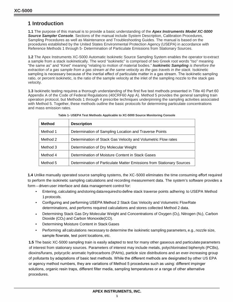
1.3 Isokinetic testing requires a thorough understanding of the first five test methods presented in Title 40 Part 60 Appendix A of the Code of Federal Regulations (40CRF60 App A). Method 5 provides the general sampling train operation protocol, but Methods 1 through 4 prescribe techniques underpinning the sampling activities associated with Method 5. Together, these methods outline the basic protocols for determining particulate concentrations and mass emission rates.
Table 1- USEPA Test Methods Applicable to XC-5000 Source Monitoring Console
Method Description
Method 1 Determination of Sampling Location and Traverse Points
Method 2 Determination of Stack Gas Velocity and Volumetric Flow rates
Method 3 Determination of Dry Molecular Weight
Method 4 Determination of Moisture Content in Stack Gases
Method 5 Determination of Particulate Matter Emissions from Stationary Sources
1.4 Unlike manually operated source sampling systems, the XC -5000 eliminates the time consuming effort required to perform the isokinetic sampling calculations and recording measurement data. The system’s software provides a form – driven user interface and data management control for:
• Entering, calculating and storing data required to define stack traverse points adhering to USEPA Method 1 protocols.
• Configuring and performing USEPA Method 2 Stack Gas Velocity and Volumetric Flow Rate determinations, and performs required calculations and stores collected Method 2 data.
• Determining Stack Gas Dry Molecular Weight and Concentrations of Oxygen (O2), Nitrogen (N2), Carbon Dioxide (CO2) and Carbon Monoxide(CO).
• Determining Moisture Content in Stack Gases • Performing all calculations necessary to determine the isokinetic sampling parameters, e.g., nozzle size,
sample flowrate, test point locations, etc.
1.5 The basic XC-5000 sampling train is easily adapted to test for many other gaseous and particulate parameters of interest from stationary sources. Parameters of interest may include metals, polychlorinated biphenyls (PCBs), dioxins/furans, polycyclic aromatic hydrocarbons (PAHs), particle size distributions and an ever-increasing group of pollutants by adaptations of basic test methods. While the different methods are designated by other US EPA or agency method numbers, they are variations of Method 5 procedures such as using: different impinger solutions, organic resin traps, different filter media, sampling temperatures or a range of other alternative procedures.
XC-5000
APEX INSTRUMENTS, INC. 2
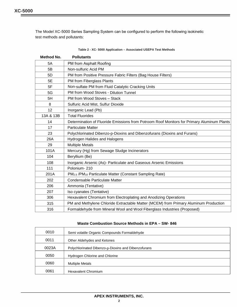
The Model XC-5000 Series Sampling System can be configured to perform the following isokinetic test methods and pollutants:
Table 2 - XC- 5000 Application – Associated USEPA Test Methods
Method No. Pollutants 5A PM from Asphalt Roofing 5B Non-sulfuric Acid PM 5D PM from Positive Pressure Fabric Filters (Bag House Filters) 5E PM from Fiberglass Plants 5F Non-sulfate PM from Fluid Catalytic Cracking Units 5G PM from Wood Stoves - Dilution Tunnel 5H PM from Wood Stoves – Stack 8 Sulfuric Acid Mist, Sulfur Dioxide 12 Inorganic Lead (Pb)
13A & 13B Total Fluorides 14 Determination of Fluoride Emissions from Potroom Roof Monitors for Primary Aluminum Plants 17 Particulate Matter 23 Polychlorinated Dibenzo-p-Dioxins and Dibenzofurans (Dioxins and Furans)
26A Hydrogen Halides and Halogens 29 Multiple Metals
101A Mercury (Hg) from Sewage Sludge Incinerators 104 Beryllium (Be) 108 Inorganic Arsenic (As)- Particulate and Gaseous Arsenic Emissions 111 Polonium- 210 201A PM2.5 /PM10 Particulate Matter (Constant Sampling Rate) 202 Condensable Particulate Matter 206 Ammonia (Tentative) 207 Iso cyanates (Tentative) 306 Hexavalent Chromium from Electroplating and Anodizing Operations 315 PM and Methylene Chloride Extractable Matter (MCEM) from Primary Aluminum Production 316 Formaldehyde from Mineral Wool and Wool Fiberglass Industries (Proposed)
Waste Combustion Source Methods in EPA – SW- 846
0010 Semi volatile Organic Compounds Formaldehyde
0011 Other Aldehydes and Ketones
0023A Polychlorinated Dibenzo-p-Dioxins and Dibenzofurans
0050 Hydrogen Chlorine and Chlorine
0060 Multiple Metals
0061 Hexavalent Chromium
XC-5000
APEX INSTRUMENTS, INC. 3
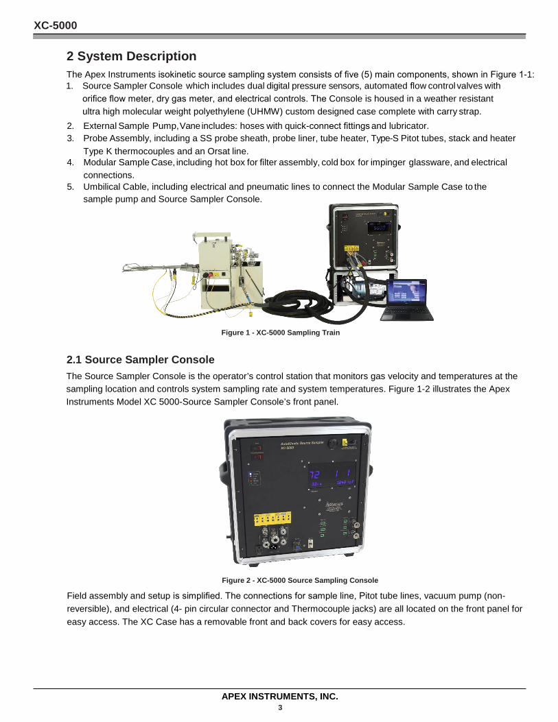
2 System Description The Apex Instruments isokinetic source sampling system consists of five (5) main components, shown in Figure 1-1: 1. Source Sampler Console which includes dual digital pressure sensors, automated flow control valves with
orifice flow meter, dry gas meter, and electrical controls. The Console is housed in a weather resistant ultra high molecular weight polyethylene (UHMW) custom designed case complete with carry strap.
2. External Sample Pump, Vane includes: hoses with quick-connect fittings and lubricator. 3. Probe Assembly, including a SS probe sheath, probe liner, tube heater, Type-S Pitot tubes, stack and heater
Type K thermocouples and an Orsat line. 4. Modular Sample Case, including hot box for filter assembly, cold box for impinger glassware, and electrical
connections. 5. Umbilical Cable, including electrical and pneumatic lines to connect the Modular Sample Case to the
sample pump and Source Sampler Console.
2.1 Source Sampler Console
Figure 1 - XC-5000 Sampling Train
The Source Sampler Console is the operator’s control station that monitors gas velocity and temperatures at the sampling location and controls system sampling rate and system temperatures. Figure 1-2 illustrates the Apex Instruments Model XC 5000-Source Sampler Console’s front panel.
Figure 2 - XC-5000 Source Sampling Console
Field assembly and setup is simplified. The connections for sample line, Pitot tube lines, vacuum pump (non- reversible), and electrical (4- pin circular connector and Thermocouple jacks) are all located on the front panel for easy access. The XC Case has a removable front and back covers for easy access.
XC-5000
APEX INSTRUMENTS, INC. 4
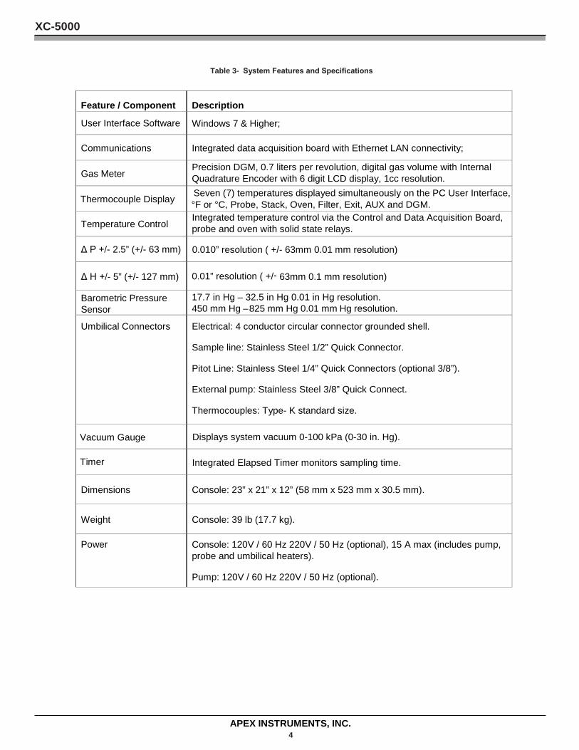
Table 3- System Features and Specifications
Feature / Component Description
User Interface Software Windows 7 & Higher;
Communications Integrated data acquisition board with Ethernet LAN connectivity;
Gas Meter Precision DGM, 0.7 liters per revolution, digital gas volume with Internal Quadrature Encoder with 6 digit LCD display, 1cc resolution.
Thermocouple Display Seven (7) temperatures displayed simultaneously on the PC User Interface, °F or °C, Probe, Stack, Oven, Filter, Exit, AUX and DGM.
Temperature Control Integrated temperature control via the Control and Data Acquisition Board, probe and oven with solid state relays.
Δ P +/- 2.5” (+/- 63 mm) 0.010” resolution ( +/- 63mm 0.01 mm resolution)
Δ H +/- 5” (+/- 127 mm) 0.01” resolution ( +/- 63mm 0.1 mm resolution)
Barometric Pressure Sensor
17.7 in Hg – 32.5 in Hg 0.01 in Hg resolution. 450 mm Hg – 825 mm Hg 0.01 mm Hg resolution.
Umbilical Connectors Electrical: 4 conductor circular connector grounded shell.
Sample line: Stainless Steel 1/2” Quick Connector.
Pitot Line: Stainless Steel 1/4” Quick Connectors (optional 3/8”).
External pump: Stainless Steel 3/8” Quick Connect.
Thermocouples: Type- K standard size.
Vacuum Gauge Displays system vacuum 0-100 kPa (0-30 in. Hg).
Timer Integrated Elapsed Timer monitors sampling time.
Dimensions Console: 23” x 21” x 12” (58 mm x 523 mm x 30.5 mm).
Weight Console: 39 lb (17.7 kg).
Power Console: 120V / 60 Hz 220V / 50 Hz (optional), 15 A max (includes pump, probe and umbilical heaters).
Pump: 120V / 60 Hz 220V / 50 Hz (optional).
XC-5000
APEX INSTRUMENTS, INC. 5
2.2 User Interface Software The configuration and operation of the XC- 5000 is completely controlled through the system’s User Interface software and the operating system running on the XC-5000 embedded computer resident on the Console’s mother board.
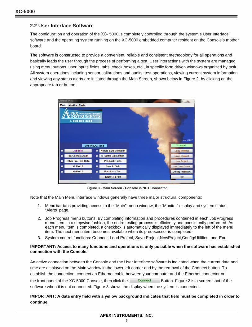
The software is constructed to provide a convenient, reliable and consistent methodology for all operations and basically leads the user through the process of performing a test. User interactions with the system are managed using menu buttons, user inputs fields, tabs, check boxes, etc., in specific form driven windows organized by task. All system operations including sensor calibrations and audits, test operations, viewing current system information and viewing any status alerts are initiated through the Main Screen, shown below in Figure 2, by clicking on the appropriate tab or button.
Figure 3 - Main Screen - Console is NOT Connected
Note that the Main Menu interface windows generally have three major structural components:
1. Menu bar tabs providing access to the “Main” menu window, the “Monitor” display and system status “Alerts” page.
2. Job Progress menu buttons. By completing information and procedures contained in each Job Progress menu item, in a stepwise fashion, the entire testing process is efficiently and consistently performed. As each menu item is completed, a checkbox is automatically displayed immediately to the left of the menu item. The next menu item becomes available when its predecessor is completed.
3. System control functions: Connect, Load Project, Save Project,NewProject,Config/Utilities, and End.
IMPORTANT: Access to many functions and operations is only possible when the software has established connection with the Console.
An active connection between the Console and the User Interface software is indicated when the current date and time are displayed on the Main window in the lower left corner and by the removal of the Connect button. To establish the connection, connect an Ethernet cable between your computer and the Ethernet connector on the front panel of the XC-5000 Console, then click the . Button. Figure 2 is a screen shot of the software when it is not connected. Figure 3 shows the display when the system is connected.
IMPORTANT: A data entry field with a yellow background indicates that field must be completed in order to continue.
XC-5000
APEX INSTRUMENTS, INC. 6
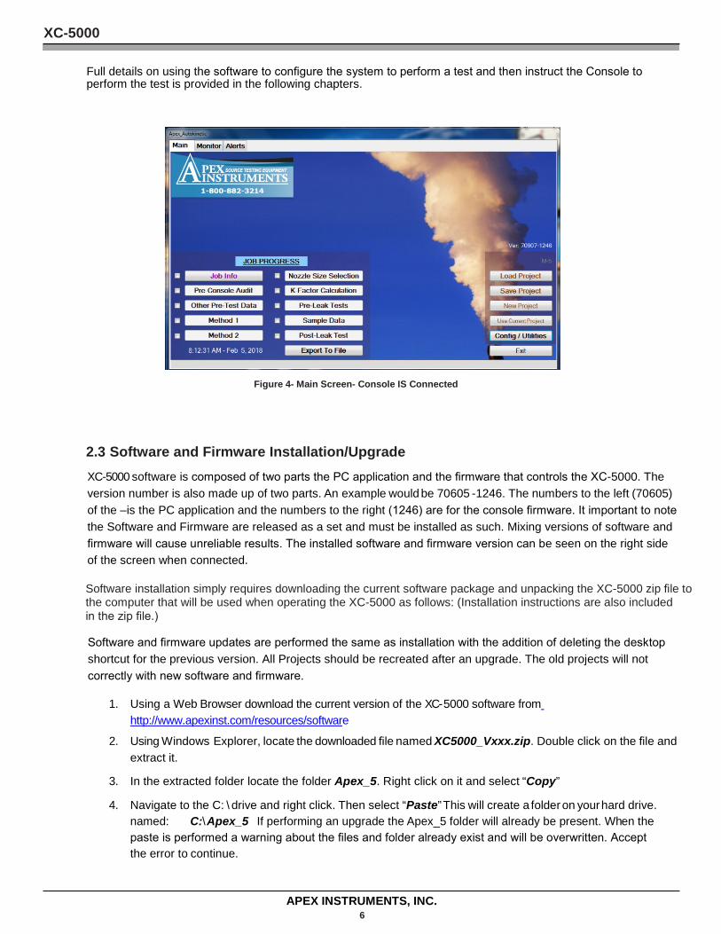
Full details on using the software to configure the system to perform a test and then instruct the Console to perform the test is provided in the following chapters.
Figure 4- Main Screen- Console IS Connected
2.3 Software and Firmware Installation/Upgrade XC-5000 software is composed of two parts the PC application and the firmware that controls the XC-5000. The version number is also made up of two parts. An example would be 70605 -1246. The numbers to the left (70605) of the –is the PC application and the numbers to the right (1246) are for the console firmware. It important to note the Software and Firmware are released as a set and must be installed as such. Mixing versions of software and firmware will cause unreliable results. The installed software and firmware version can be seen on the right side of the screen when connected.
Software installation simply requires downloading the current software package and unpacking the XC-5000 zip file to the computer that will be used when operating the XC-5000 as follows: (Installation instructions are also included in the zip file.)
Software and firmware updates are performed the same as installation with the addition of deleting the desktop shortcut for the previous version. All Projects should be recreated after an upgrade. The old projects will not correctly with new software and firmware.
1. Using a Web Browser download the current version of the XC- 5000 software from http://www.apexinst.com/resources/software
2. Using Windows Explorer, locate the downloaded file named XC5000_Vxxx.zip. Double click on the file and extract it.
3. In the extracted folder locate the folder Apex_5. Right click on it and select “Copy”
4. Navigate to the C: \ drive and right click. Then select “Paste” This will create a folder on your hard drive. named: C:\ Apex_5. If performing an upgrade the Apex_5 folder will already be present. When the paste is performed a warning about the files and folder already exist and will be overwritten. Accept the error to continue.
XC-5000
APEX INSTRUMENTS, INC. 7
5. Navigate to the Apex_5 folder. In this folder locate the file Apex_AutoKinetic_xxxxx. Right click on the file and select “Send to Desktop” This will create a shortcut to the application on the Desktop, shown below, on your desktop. If performing an update delete the old version shortcut from the desktop.
By default, all data and audit files created by the XC -5000 software during a test will be stored in the C:\ Apex_5 folder.
6. Make sure the PC and laptop are powered on and connect the PC to XC-5000 with Ethernet cable.
7. Double click the desktop icon to launch the application.
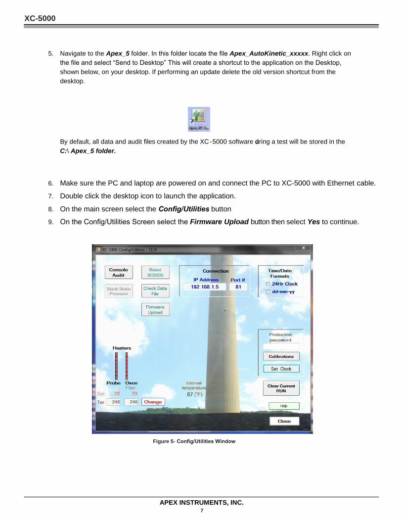
8. On the main screen select the Config/Utilities button
9. On the Config/Utilities Screen select the Firmware Upload button then select Yes to continue.
Figure 5- Config/Utilities Window

XC-5000
APEX INSTRUMENTS, INC. 8
Figure 4 Config / Utilities Screen
10. Navigate to the C:\ Apex_5 folder if not there by default. Select the Main firmware 5_Mainxxx.hex where xxx is the version number. Select Open
Figure 6 Firmware File Selection C:\ Apex_5 Folder
Figure 7 Firmware Upload Successful Window
11. The PC will automatically connect to the XC-5000.
XC-5000
APEX INSTRUMENTS, INC. 9
2.4 Electrical SubSystem The Source Sampler Console is factory- configured for 120VAC/60Hz electrical power. Configuration for 240VAC/50Hz operation is an available option. The Electrical Schematics for the Source Sampler Console are presented in Appendix B.
Circuits are protected by front panel mounted circuit breaker switches labeled Main (15 Amp for 110VAC or 10 Amp for 220VAC) and PUMP/OVEN/HEATERS. Circuit breakers detect and interrupt overload and short circuit conditions, providing an important safety factor. If the circuit breaker opens, or “trips,” indicating interruption of the circuit, investigate and repair the electrical fault. Then reset the breaker by toggling the power/circuit breaker switch off then on
The electrical subsystem provides switched power to several circuits, including: MAIN POWER, PUMP POWER, PROBE heater and OVEN heater.
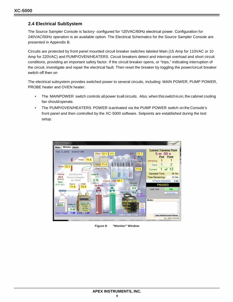
• The MAINPOWER switch controls all power to all circuits. Also, when this switch is on, the cabinet cooling fan should operate.
• The PUMP/OVEN/HEATERS POWER is activated via the PUMP POWER switch on the Console’s front panel and then controlled by the XC -5000 software. Setpoints are established during the test setup.
Figure 8- "Monitor" Window
XC-5000
APEX INSTRUMENTS, INC. 10
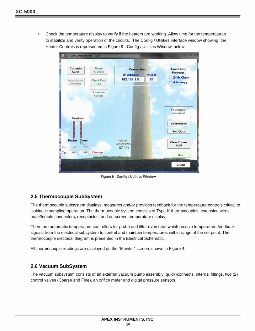
• Check the temperature display to verify if the heaters are working. Allow time for the temperatures to stabilize and verify operation of the circuits. The Config / Utilities interface window showing the Heater Controls is represented in Figure 9 - Config / Utilities Window, below.
Figure 9 - Config / Utilities Window
2.5 Thermocouple SubSystem The thermocouple subsystem displays, measures and/or provides feedback for the temperature controls critical to isokinetic sampling operation. The thermocouple system consists of Type-K thermocouples, extension wires, male/female connectors, receptacles, and on-screen temperature display.
There are automatic temperature controllers for probe and filter oven heat which receive temperature feedback signals from the electrical subsystem to control and maintain temperatures within range of the set point. The thermocouple electrical diagram is presented in the Electrical Schematic.
All thermocouple readings are displayed on the “Monitor” screen, shown in Figure 4.
2.6 Vacuum SubSystem The vacuum subsystem consists of an external vacuum pump assembly, quick-connects, internal fittings, two (2) control valves (Coarse and Fine), an orifice meter and digital pressure sensors.
XC-5000
APEX INSTRUMENTS, INC. 11
The external vacuum pump assembly provides the vacuum for extracting the gas sample from the stack and then through the various components of the isokinetic source sampling system.
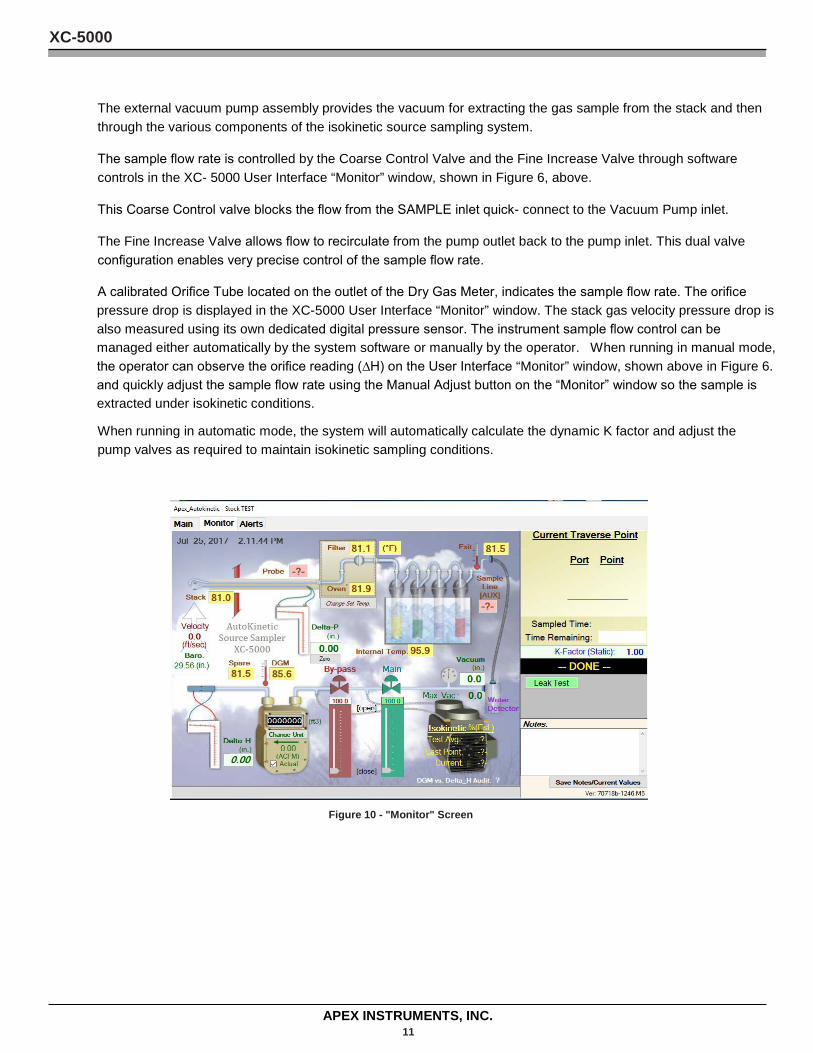
The sample flow rate is controlled by the Coarse Control Valve and the Fine Increase Valve through software controls in the XC- 5000 User Interface “Monitor” window, shown in Figure 6, above.
This Coarse Control valve blocks the flow from the SAMPLE inlet quick- connect to the Vacuum Pump inlet.
The Fine Increase Valve allows flow to recirculate from the pump outlet back to the pump inlet. This dual valve configuration enables very precise control of the sample flow rate.
A calibrated Orifice Tube located on the outlet of the Dry Gas Meter, indicates the sample flow rate. The orifice pressure drop is displayed in the XC-5000 User Interface “Monitor” window. The stack gas velocity pressure drop is also measured using its own dedicated digital pressure sensor. The instrument sample flow control can be managed either automatically by the system software or manually by the operator. When running in manual mode, the operator can observe the orifice reading (∆H) on the User Interface “Monitor” window, shown above in Figure 6. and quickly adjust the sample flow rate using the Manual Adjust button on the “Monitor” window so the sample is extracted under isokinetic conditions.
When running in automatic mode, the system will automatically calculate the dynamic K factor and adjust the pump valves as required to maintain isokinetic sampling conditions.
Figure 10 - "Monitor" Screen
XC-5000
APEX INSTRUMENTS, INC. 12
3 Operating Procedures Conducting a Test The XC-5000 Source Sampling System has been designed and developed to perform a test following USEPA stationary source testing methodology. The XC -5000 software design considers each individual sample run comprising one or more traverse points and traverse lines as a single “Test”.
The hardware and software work together to guide the user through the entire test process including Methods 1 through 4, necessary for gathering the preliminary values for Method 5 sampling, all associated system leak checks, sensor calibration/audits and then performing the Method 5 test.
It is vitally important that the system operator follow the Console’s menu structure in order to carry out a valid test in conformance with USEPA method requirements. By accurately completing required user input data and conducting the test according to method protocols, the XC-5000 ensures the completion of a valid test run. During the conduct of the test, the software performs all required calculations and automatically monitors the status of all system sensors and operating parameters and also provides operator prompts, for example, when to change the test point location.
Each test results in a test run specific data file (.CSV format) containing all required preliminary values including user desired test and site identification details, quality control checks, sensor parameter data.
As mentioned previously, the User Interface software menus have been constructed to follow the logic and steps used in the USEPA’s source testing methods. Any and all necessary calculations in the methods are normally performed automatically by the XC-5000 User Interface software and operating system firmware.
These features will be evident as the test is configured and carried out.
This chapter has been divided into several sections detailing each part of the test process: 3-1. Establish Communications 3-2. Complete Job Info 3-3. Attach Pre -Test Console Audit 3-4. Complete Other Pre -Test Data 3-5. Complete Method 1 3-6. Complete Method 2 3-7. Calculate Nozzle Size 3-8. K Factor Determination and Configuration 3-9. Perform Pre-Test Leak Check
3-10. Conduct Sample Traverse 3-11. Perform Post -Test Leak Checks
Where appropriate, the operational details, requirements and calculations underpinning Methods 1 – 5 have been retained in the following sections to provide background on what is being performed by the instrument when a test is being conducted.
XC-5000
APEX INSTRUMENTS, INC. 13
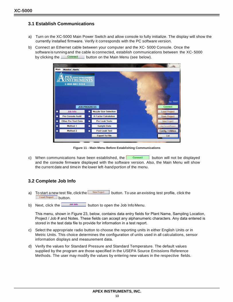
3.1 Establish Communications
a) Turn on the XC-5000 Main Power Switch and allow console to fully initialize. The display will show the currently installed firmware. Verify it corresponds with the PC software version.
b) Connect an Ethernet cable between your computer and the XC- 5000 Console. Once the software is running and the cable is connected, establish communications between the XC- 5000 by clicking the button on the Main Menu (see below).
Figure 11 - Main Menu Before Establishing Communications
c) When communications have been established, the button will not be displayed
and the console firmware displayed with the software version. Also, the Main Menu will show the current date and time in the lower left -hand portion of the menu.
3.2 Complete Job Info
a) To start a new test file, click the button. To use an existing test profile, click the
button.
b) Next, click the button to open the Job Info Menu.
This menu, shown in Figure 23, below, contains data entry fields for Plant Name, Sampling Location, Project / Job # and Notes. These fields can accept any alphanumeric characters. Any data entered is stored in the test data file to provide for information in a test report.
c) Select the appropriate radio button to choose the reporting units in either English Units or in Metric Units. This choice determines the configuration of units used in all calculations, sensor information displays and measurement data.
d) Verify the values for Standard Pressure and Standard Temperature. The default values supplied by the program are those specified in the USEPA Source Emissions Reference Methods. The user may modify the values by entering new values in the respective fields.
XC-5000
APEX INSTRUMENTS, INC. 14
the
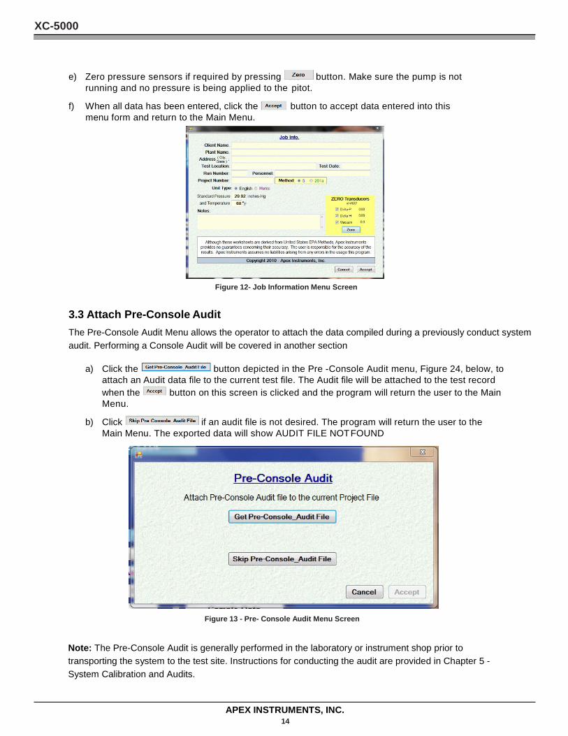
e) Zero pressure sensors if required by pressing button. Make sure the pump is not running and no pressure is being applied to the pitot.
f) When all data has been entered, click the button to accept data entered into this menu form and return to the Main Menu.
Figure 12- Job Information Menu Screen
3.3 Attach Pre-Console Audit The Pre-Console Audit Menu allows the operator to attach the data compiled during a previously conduct system audit. Performing a Console Audit will be covered in another section
a) Click the button depicted in the Pre -Console Audit menu, Figure 24, below, to attach an Audit data file to the current test file. The Audit file will be attached to the test record when the button on this screen is clicked and the program will return the user to the Main Menu.
b) Click if an audit file is not desired. The program will return the user to the Main Menu. The exported data will show AUDIT FILE NOT FOUND
Figure 13 - Pre- Console Audit Menu Screen
Note: The Pre-Console Audit is generally performed in the laboratory or instrument shop prior to transporting the system to the test site. Instructions for conducting the audit are provided in Chapter 5 - System Calibration and Audits.
XC-5000
APEX INSTRUMENTS, INC. 15
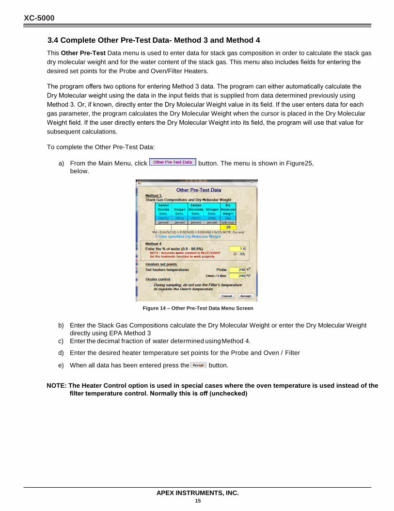
3.4 Complete Other Pre-Test Data- Method 3 and Method 4 This Other Pre-Test Data menu is used to enter data for stack gas composition in order to calculate the stack gas dry molecular weight and for the water content of the stack gas. This menu also includes fields for entering the desired set points for the Probe and Oven/Filter Heaters.
The program offers two options for entering Method 3 data. The program can either automatically calculate the Dry Molecular weight using the data in the input fields that is supplied from data determined previously using Method 3. Or, if known, directly enter the Dry Molecular Weight value in its field. If the user enters data for each gas parameter, the program calculates the Dry Molecular Weight when the cursor is placed in the Dry Molecular Weight field. If the user directly enters the Dry Molecular Weight into its field, the program will use that value for subsequent calculations.
To complete the Other Pre-Test Data:
a) From the Main Menu, click button. The menu is shown in Figure25, below.
Figure 14 – Other Pre-Test Data Menu Screen
b) Enter the Stack Gas Compositions calculate the Dry Molecular Weight or enter the Dry Molecular Weight
directly using EPA Method 3 c) Enter the decimal fraction of water determined using Method 4.
d) Enter the desired heater temperature set points for the Probe and Oven / Filter
e) When all data has been entered press the button.
NOTE: The Heater Control option is used in special cases where the oven temperature is used instead of the filter temperature control. Normally this is off (unchecked)
XC-5000
APEX INSTRUMENTS, INC. 16
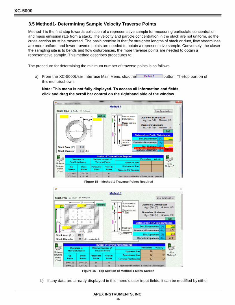
3.5 Method1- Determining Sample Velocity Traverse Points Method 1 is the first step towards collection of a representative sample for measuring particulate concentration and mass emission rate from a stack. The velocity and particle concentration in the stack are not uniform, so the cross-section must be traversed. The basic premise is that for straighter lengths of stack or duct, flow streamlines are more uniform and fewer traverse points are needed to obtain a representative sample. Conversely, the closer the sampling site is to bends and flow disturbances, the more traverse points are needed to obtain a representative sample. This method describes procedures to:
The procedure for determining the minimum number of traverse points is as follows:
a) From the XC-5000User Interface Main Menu, click the button. The top portion of
this menu is shown.
Note: This menu is not fully displayed. To access all information and fields, click and drag the scroll bar control on the righthand side of the window.
Figure 15 – Method 1 Traverse Points Required
Figure 16 - Top Section of Method 1 Menu Screen
b) If any data are already displayed in this menu’s user input fields, it can be modified by either
XC-5000
APEX INSTRUMENTS, INC. 17
entering the new value in each field or by clicking the button to clear all fields in this form.
c) Select the StackType (Circular or Rectangular) by clicking on the appropriate radio button.
d) Enter the length from the far inside wall of the stack to the port flange face (Lfw ).
Note: Be sure to enter data in the appropriate units of measure as shown on the labels next to the data input fields.
e) Enter the length from the near inside wall of the stack to the port flange face (Lnw). f) Enter the distances to the Downstream and Upstream Disturbances.
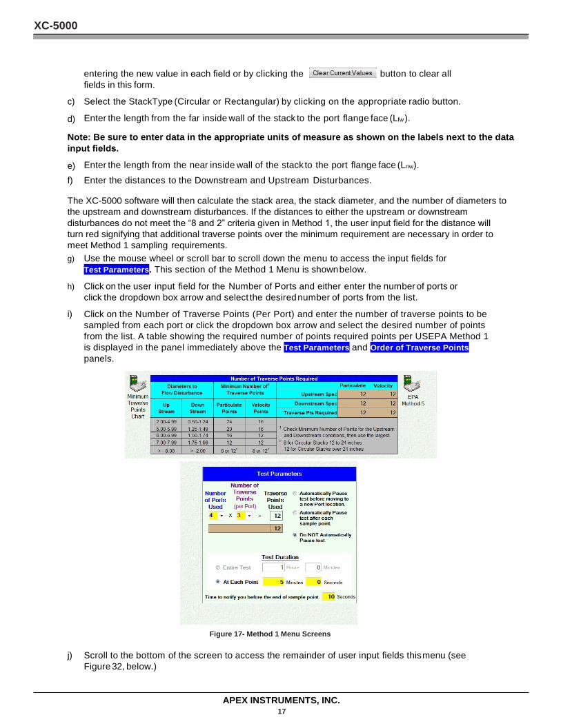
The XC-5000 software will then calculate the stack area, the stack diameter, and the number of diameters to the upstream and downstream disturbances. If the distances to either the upstream or downstream disturbances do not meet the “8 and 2” criteria given in Method 1, the user input field for the distance will turn red signifying that additional traverse points over the minimum requirement are necessary in order to meet Method 1 sampling requirements. g) Use the mouse wheel or scroll bar to scroll down the menu to access the input fields for
Test Parameters. This section of the Method 1 Menu is shown below.
h) Click on the user input field for the Number of Ports and either enter the number of ports or click the dropdown box arrow and select the desired number of ports from the list.
i) Click on the Number of Traverse Points (Per Port) and enter the number of traverse points to be sampled from each port or click the dropdown box arrow and select the desired number of points from the list. A table showing the required number of points required points per USEPA Method 1 is displayed in the panel immediately above the Test Parameters and Order of Traverse Points panels.
Figure 17- Method 1 Menu Screens
j) Scroll to the bottom of the screen to access the remainder of user input fields this menu (see Figure 32, below.)
XC-5000
APEX INSTRUMENTS, INC. 18
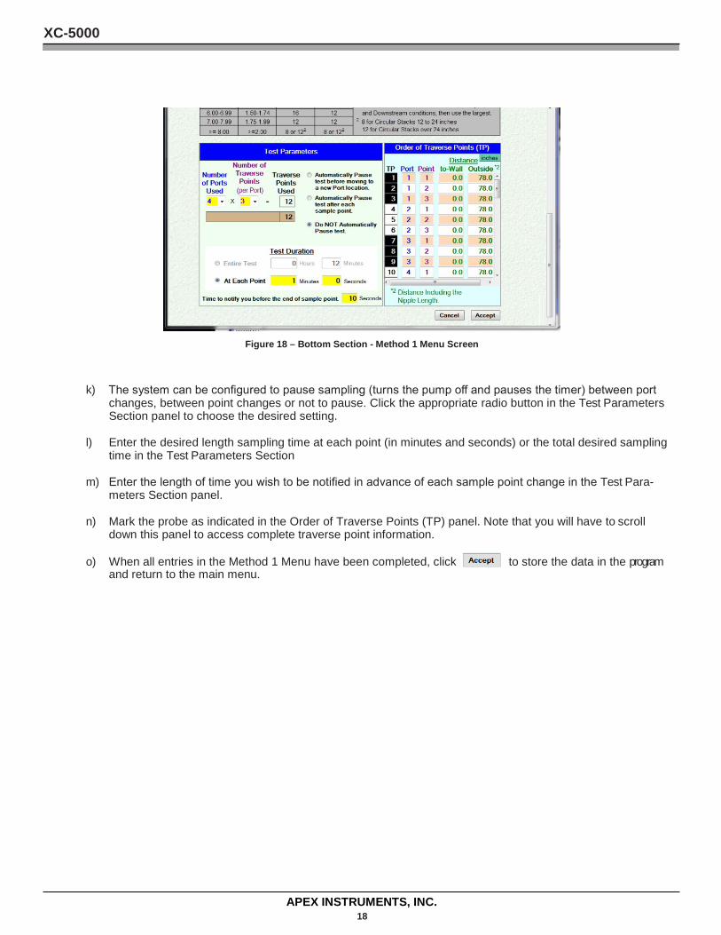
Figure 18 – Bottom Section - Method 1 Menu Screen
k) The system can be configured to pause sampling (turns the pump off and pauses the timer) between port changes, between point changes or not to pause. Click the appropriate radio button in the Test Parameters Section panel to choose the desired setting.
l) Enter the desired length sampling time at each point (in minutes and seconds) or the total desired sampling time in the Test Parameters Section
m) Enter the length of time you wish to be notified in advance of each sample point change in the Test Para- meters Section panel.
n) Mark the probe as indicated in the Order of Traverse Points (TP) panel. Note that you will have to scroll down this panel to access complete traverse point information.
o) When all entries in the Method 1 Menu have been completed, click to store the data in the program and return to the main menu.
XC-5000
APEX INSTRUMENTS, INC. 19
3.6 Method 2- Stack Gas Velocity and Volumetric Flow Rate Method 2 is used to measure the average velocity and volumetric flow rate of the stack gas. There are two instances where Method 2 would be used:
Prior to a particulate stack test series, to determine the size of the nozzle and length of the sampling run (preliminary velocity determination).
During each stack test run, to ensure that the particulate sample is extracted from the stack at isokinetic conditions.
The procedure for determining flow rate (preliminary or other) in a stack gas stream is as follows:
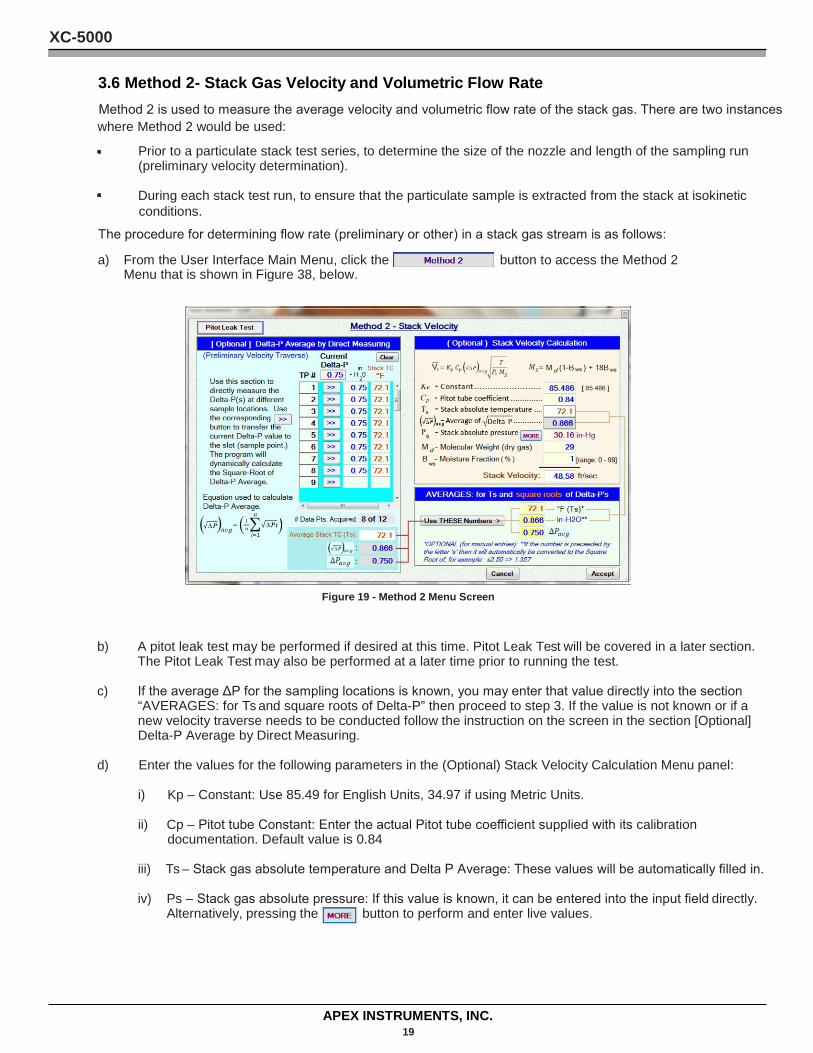
a) From the User Interface Main Menu, click the button to access the Method 2 Menu that is shown in Figure 38, below.
Figure 19 - Method 2 Menu Screen
b) A pitot leak test may be performed if desired at this time. Pitot Leak Test will be covered in a later section. The Pitot Leak Test may also be performed at a later time prior to running the test.
c) If the average ΔP for the sampling locations is known, you may enter that value directly into the section “AVERAGES: for Ts and square roots of Delta-P” then proceed to step 3. If the value is not known or if a new velocity traverse needs to be conducted follow the instruction on the screen in the section [Optional] Delta-P Average by Direct Measuring.
d) Enter the values for the following parameters in the (Optional) Stack Velocity Calculation Menu panel:
i) Kp – Constant: Use 85.49 for English Units, 34.97 if using Metric Units.
ii) Cp – Pitot tube Constant: Enter the actual Pitot tube coefficient supplied with its calibration documentation. Default value is 0.84
iii) Ts – Stack gas absolute temperature and Delta P Average: These values will be automatically filled in.
iv) Ps – Stack gas absolute pressure: If this value is known, it can be entered into the input field directly. Alternatively, pressing the button to perform and enter live values.
XC-5000
APEX INSTRUMENTS, INC. 20
Figure 20 – Stack Static Pressure
v) ΔP – Average Velocity Head: This value is imported automatically from the Delta -P Avg field in the (Optional) Delta-P Average by Direct Measuring Menu panel.
vi) Md – Molecular Weight (dry gas): This value is supplied automatically from the completed “Other Pre-Test Information” menu. If the value being displayed is not acceptable, enter the new value in the input field.
vii) Bws – Moisture Fraction: This value is also supplied automatically from the completed “Other Pre-Test Information” menu. If the value being displayed is not acceptable, enter the new value in the input field.
e) When all data have been entered, click the button at the bottom of the screen
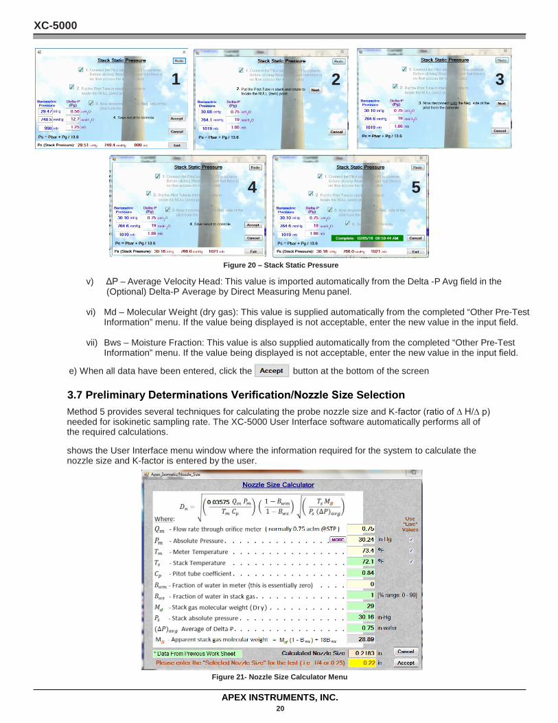
3.7 Preliminary Determinations Verification/Nozzle Size Selection Method 5 provides several techniques for calculating the probe nozzle size and K-factor (ratio of ∆ H/∆ p) needed for isokinetic sampling rate. The XC-5000 User Interface software automatically performs all of the required calculations.
shows the User Interface menu window where the information required for the system to calculate the nozzle size and K-factor is entered by the user.
Figure 21- Nozzle Size Calculator Menu
5 4
3 2 1
XC-5000
APEX INSTRUMENTS, INC. 21
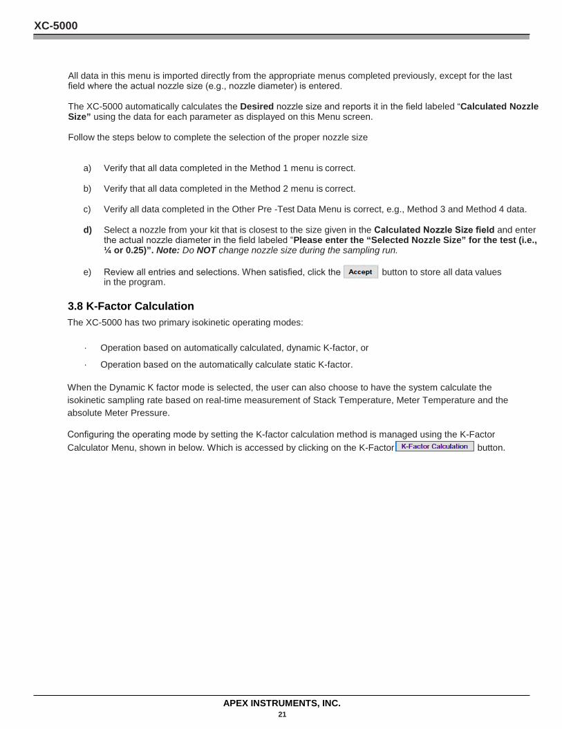
All data in this menu is imported directly from the appropriate menus completed previously, except for the last field where the actual nozzle size (e.g., nozzle diameter) is entered.
The XC-5000 automatically calculates the Desired nozzle size and reports it in the field labeled “Calculated Nozzle Size” using the data for each parameter as displayed on this Menu screen.
Follow the steps below to complete the selection of the proper nozzle size
a) Verify that all data completed in the Method 1 menu is correct.
b) Verify that all data completed in the Method 2 menu is correct.
c) Verify all data completed in the Other Pre -Test Data Menu is correct, e.g., Method 3 and Method 4 data.
d) Select a nozzle from your kit that is closest to the size given in the Calculated Nozzle Size field and enter the actual nozzle diameter in the field labeled “Please enter the “Selected Nozzle Size” for the test (i.e., ¼ or 0.25)”. Note: Do NOT change nozzle size during the sampling run.
e) Review all entries and selections. When satisfied, click the button to store all data values in the program.
3.8 K-Factor Calculation The XC-5000 has two primary isokinetic operating modes:
· Operation based on automatically calculated, dynamic K-factor, or
· Operation based on the automatically calculate static K-factor.
When the Dynamic K factor mode is selected, the user can also choose to have the system calculate the isokinetic sampling rate based on real-time measurement of Stack Temperature, Meter Temperature and the absolute Meter Pressure.
Configuring the operating mode by setting the K-factor calculation method is managed using the K-Factor Calculator Menu, shown in below. Which is accessed by clicking on the K-Factor button.
XC-5000
APEX INSTRUMENTS, INC. 22
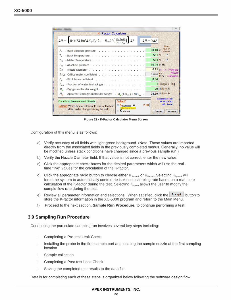
Figure 22 - K-Factor Calculator Menu Screen
Configuration of this menu is as follows:
a) Verify accuracy of all fields with light green background. (Note: These values are imported directly from the associated fields in the previously completed menus. Generally, no value will be modified unless stack conditions have changed since a previous sample run.)
b) Verify the Nozzle Diameter field. If that value is not correct, enter the new value. c) Click the appropriate check boxes for the desired parameters which will use the real -
time “live” values for the calculation of the K-factor.
d) Click the appropriate radio button to choose either K Dynamic or KManual . Selecting KDynamic will force the system to automatically control the isokinetic sampling rate based on a real -time calculation of the K-factor during the test. Selecting KManual allows the user to modify the sample flow rate during the test.
e) Review all parameter information and selections. When satisfied, click the button to store the K-factor information in the XC-5000 program and return to the Main Menu.
f) Proceed to the next section, Sample Run Procedure, to continue performing a test.
3.9 Sampling Run Procedure
Conducting the particulate sampling run involves several key steps including:
· Completing a Pre-test Leak Check
· Installing the probe in the first sample port and locating the sample nozzle at the first sampling location
· Sample collection
· Completing a Post-test Leak Check
· Saving the completed test results to the data file.
Details for completing each of these steps is organized below following the software design flow.
XC-5000
APEX INSTRUMENTS, INC. 23
a) Perform a Pre-test Leak Check
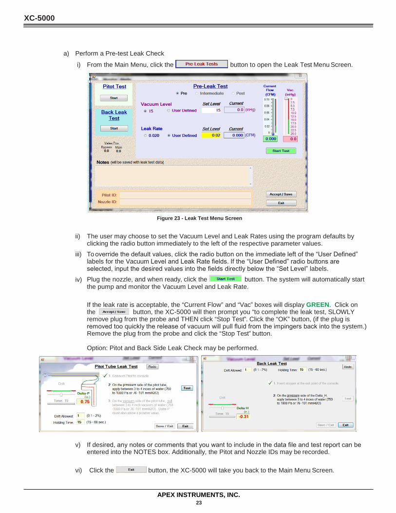
i) From the Main Menu, click the button to open the Leak Test Menu Screen.
Figure 23 - Leak Test Menu Screen
ii) The user may choose to set the Vacuum Level and Leak Rates using the program defaults by clicking the radio button immediately to the left of the respective parameter values.
iii) To override the default values, click the radio button on the immediate left of the “User Defined” labels for the Vacuum Level and Leak Rate fields. If the “User Defined” radio buttons are selected, input the desired values into the fields directly below the “Set Level” labels.
iv) Plug the nozzle, and when ready, click the button. The system will automatically start the pump and monitor the Vacuum Level and Leak Rate.
If the leak rate is acceptable, the “Current Flow” and “Vac” boxes will display GREEN. Click on the button, the XC-5000 will then prompt you “to complete the leak test, SLOWLY remove plug from the probe and THEN click “Stop Test”. Click the “OK” button, (if the plug is removed too quickly the release of vacuum will pull fluid from the impingers back into the system.) Remove the plug from the probe and click the “Stop Test” button.
Option: Pitot and Back Side Leak Check may be performed.
v) If desired, any notes or comments that you want to include in the data file and test report can be
entered into the NOTES box. Additionally, the Pitot and Nozzle IDs may be recorded.
vi) Click the button, the XC-5000 will take you back to the Main Menu Screen.
XC-5000
APEX INSTRUMENTS, INC. 24
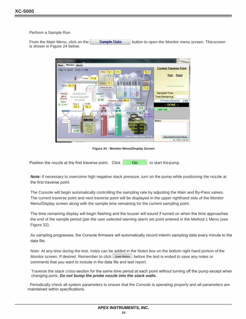
Perform a Sample Run
From the Main Menu, click on the button to open the Monitor menu screen. This screen is shown in Figure 24 below.
Figure 24 - Monitor Menu/Display Screen
Position the nozzle at the first traverse point. Click to start the pump.
Note: If necessary to overcome high negative stack pressure, turn on the pump while positioning the nozzle at the first traverse point.
The Console will begin automatically controlling the sampling rate by adjusting the Main and By-Pass valves. The current traverse point and next traverse point will be displayed in the upper righthand side of the Monitor Menu/Display screen along with the sample time remaining for the current sampling point.
The time remaining display will begin flashing and the buzzer will sound if turned on when the time approaches the end of the sample period (per the user selected warning alarm set point entered in the Method 1 Menu (see Figure 32).
As sampling progresses, the Console firmware will automatically record interim sampling data every minute to the data file.
Note: At any time during the test, notes can be added in the Notes box on the bottom right hand portion of the Monitor screen, If desired. Remember to click before the test is ended to save any notes or comments that you want to include in the data file and test report.
Traverse the stack cross-section for the same time period at each point without turning off the pump except when changing ports. Do not bump the probe nozzle into the stack walls.
Periodically check all system parameters to ensure that the Console is operating properly and all parameters are maintained within specifications.
XC-5000
APEX INSTRUMENTS, INC. 25
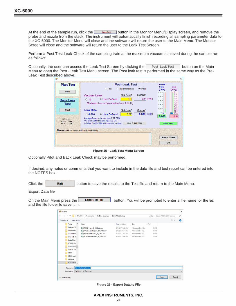
At the end of the sample run, click the button in the Monitor Menu/Display screen, and remove the probe and nozzle from the stack. The instrument will automatically finish recording all sampling parameter data to the XC-5000. The Monitor Menu will close and the software will return the user to the Main Menu. The Monitor Scree will close and the software will return the user to the Leak Test Screen.
Perform a Post Test Leak-Check of the sampling train at the maximum vacuum achieved during the sample run as follows:
Optionally, the user can access the Leak Test Screen by clicking the button on the Main Menu to open the Post -Leak Test Menu screen. The Post leak test is performed in the same way as the Pre-Leak Test described above.
Figure 25 - Leak Test Menu Screen
Optionally Pitot and Back Leak Check may be performed.
If desired, any notes or comments that you want to include in the data file and test report can be entered into the NOTES box.
Click the button to save the results to the Test file and return to the Main Menu.
Export Data file
On the Main Menu press the button. You will be prompted to enter a file name for the test and the file folder to save it in.
Figure 26 - Export Data to File
XC-5000
APEX INSTRUMENTS, INC. 26
4 Recommended Reading List for Isokinetic Sampling Code of Federal Regulations. Title 40. Part 60, Appendix A. Office of the Federal Register. National Archives and Records.
Compliance Test Coordination and Evaluation. Workshop Manual. U.S. Environmental Protection Agency. APTI 01-94a. 1994.
Jahnke, J. A., et al. Source Sampling for Particulate Pollutants. Student Manual, APTI Course 450. Edition 3.0. Raleigh, NC: North Carolina State University, 1995.
Manual for Coordination of VOC Emissions Testing Using EPA Methods 18, 21, 25, and 25A. U.S. Environmental Protection Agency. EPA 340/1-91-008. September 1991.
Quality Assurance Handbook for Air Pollution Measurement Systems. Vol. 3. Stationary Source Specific Methods, Section 3.4. U.S. Environmental Protection Agency. EPA-600/4-77-027b. 1988. Rom, J. J.
Maintenance, Calibration, and Operation of Isokinetic Source Sampling Equipment. Publication No. APTD-0576. Office of Air Programs. U.S. Environmental Protection Agency. Research Triangle Park, NC 1972
XC-5000
APEX INSTRUMENTS, INC. 27
5 System Calibrations and Audits Setting up and adhering to a routine maintenance program will help to ensure trouble-free operation of the isokinetic sampling system. In addition, a carefully documented maintenance and calibration system will help to assure that accurate results are obtained during stack testing activities. The following text describes maintenance and troubleshooting procedures for the various subsystems of the isokinetic sampling system.
Test results from a stack emission test are meaningless without calibration and audits of the equipment components. The creation and maintenance of a regularly scheduled calibration and record keeping program are critical to conducting any stack testing program. Without calibration, sampling cannot be verified as having been conducted isokinetically.
5.1 Calibration Procedures
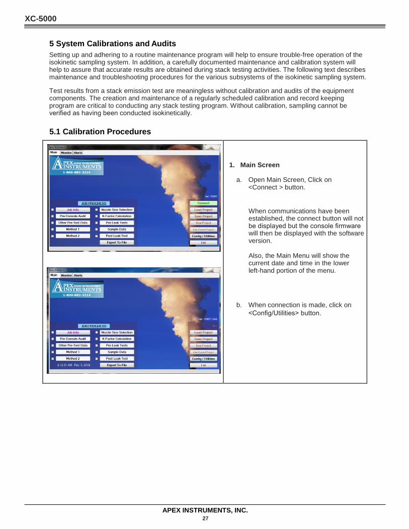
1. Main Screen
a. Open Main Screen, Click on <Connect > button.
When communications have been established, the connect button will not be displayed but the console firmware will then be displayed with the software version.
Also, the Main Menu will show the current date and time in the lower left-hand portion of the menu.
b. When connection is made, click on <Config/Utilities> button.
XC-5000
APEX INSTRUMENTS, INC. 28
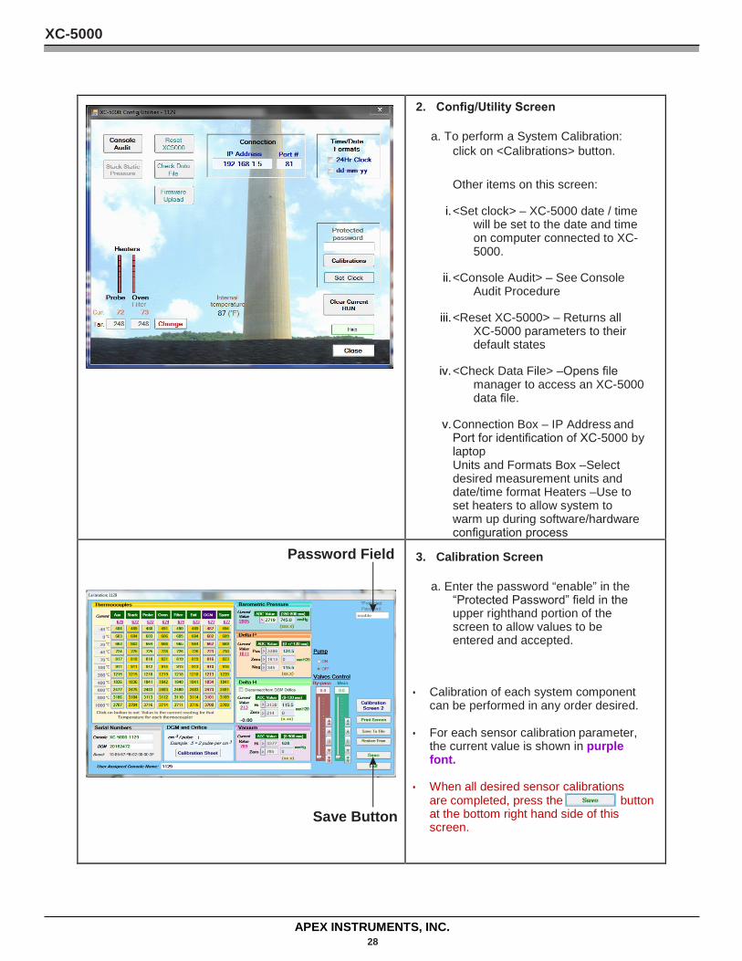
2. Config/Utility Screen
a. To perform a System Calibration: click on <Calibrations> button.
Other items on this screen:
i. <Set clock> – XC-5000 date / time will be set to the date and time on computer connected to XC-5000.
ii. <Console Audit> – See Console Audit Procedure
iii. <Reset XC-5000> – Returns all XC-5000 parameters to their default states
iv. <Check Data File> –Opens file manager to access an XC-5000 data file.
v. Connection Box – IP Address and Port for identification of XC-5000 by laptop Units and Formats Box –Select desired measurement units and date/time format Heaters –Use to set heaters to allow system to warm up during software/hardware configuration process
Password Field
Save Button
3. Calibration Screen
a. Enter the password “enable” in the “Protected Password” field in the upper righthand portion of the screen to allow values to be entered and accepted.
• Calibration of each system component can be performed in any order desired.
• For each sensor calibration parameter, the current value is shown in purple font.
• When all desired sensor calibrations are completed, press the button at the bottom right hand side of this screen.
XC-5000
APEX INSTRUMENTS, INC. 29
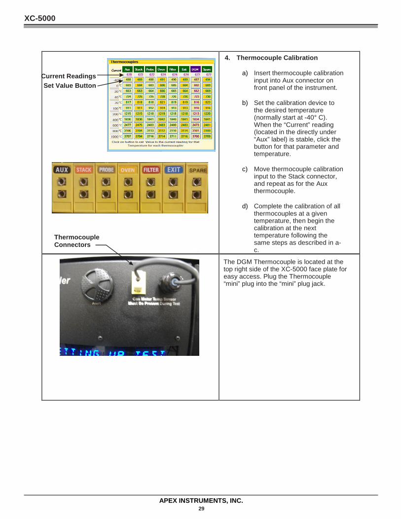
4. Thermocouple Calibration
a) Insert thermocouple calibration input into Aux connector on front panel of the instrument.
b) Set the calibration device to the desired temperature (normally start at -40° C). When the “Current” reading (located in the directly under “Aux” label) is stable, click the button for that parameter and temperature.
c) Move thermocouple calibration input to the Stack connector, and repeat as for the Aux thermocouple.
d) Complete the calibration of all thermocouples at a given temperature, then begin the calibration at the next temperature following the same steps as described in a-c.
The DGM Thermocouple is located at the top right side of the XC-5000 face plate for easy access. Plug the Thermocouple “mini” plug into the “mini” plug jack.
Thermocouple Connectors
Current Readings Set Value Button
XC-5000
APEX INSTRUMENTS, INC. 30
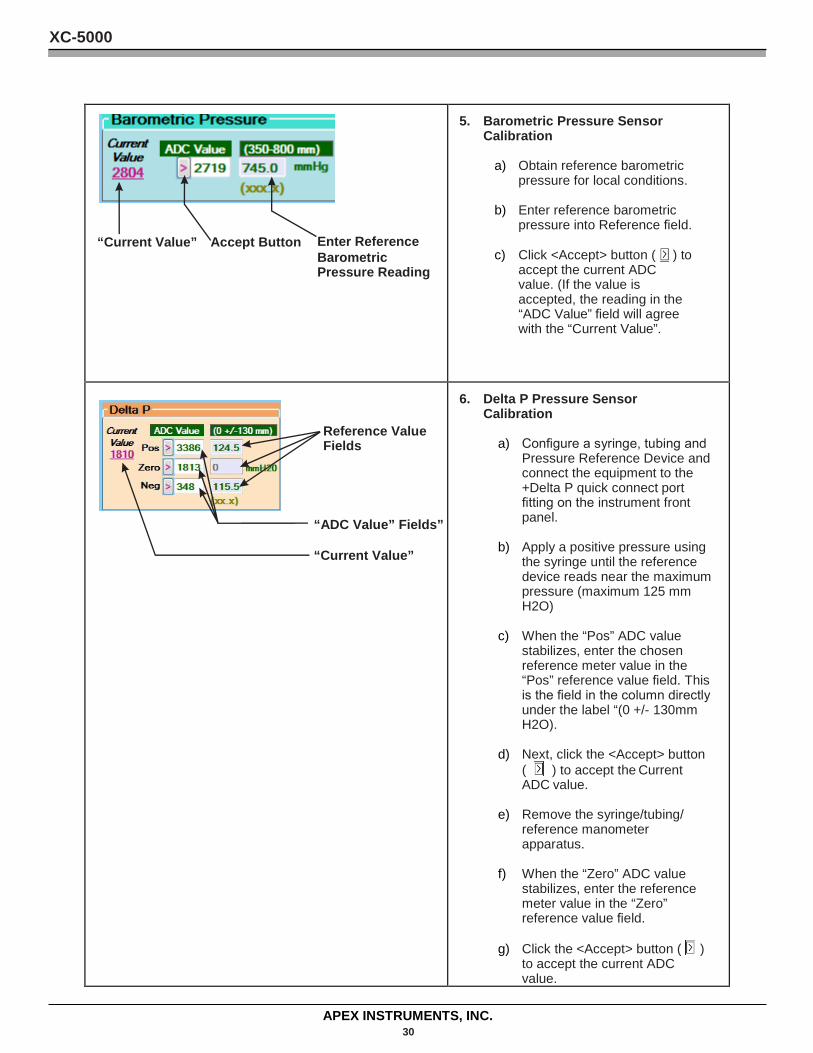
“Current Value” Accept Button Enter Reference Barometric Pressure Reading
5. Barometric Pressure Sensor Calibration
a) Obtain reference barometric pressure for local conditions.
b) Enter reference barometric pressure into Reference field.
c) Click <Accept> button ( ) to accept the current ADC value. (If the value is accepted, the reading in the “ADC Value” field will agree with the “Current Value”.
Reference Value Fields
“ADC Value” Fields”
“Current Value”
6. Delta P Pressure Sensor Calibration
a) Configure a syringe, tubing and Pressure Reference Device and connect the equipment to the +Delta P quick connect port fitting on the instrument front panel.
b) Apply a positive pressure using the syringe until the reference device reads near the maximum pressure (maximum 125 mm H2O)
c) When the “Pos” ADC value stabilizes, enter the chosen reference meter value in the “Pos” reference value field. This is the field in the column directly under the label “(0 +/- 130mm H2O).
d) Next, click the <Accept> button ( ) to accept the Current ADC value.
e) Remove the syringe/tubing/ reference manometer apparatus.
f) When the “Zero” ADC value stabilizes, enter the reference meter value in the “Zero” reference value field.
g) Click the <Accept> button ( ) to accept the current ADC value.
XC-5000
APEX INSTRUMENTS, INC. 31
Save Button
WARNING Changes in this area can adversely alter you sample volume.
Gamma This value is used to correlate the volume of the (DGM) and (WTM).
The ccm 3/pulse is a factor set by the factory that correlates the volume
measured per revolution of the meter shaft to the meter's digital encoder. DGM
rotational specifications vary from meter manufacture. To account for different
meter manufactures, this field allows the optical encoder to be calibrated to
the meter shaft rotational speed. This field is not a variable. The factor to
accommodate for various meters that have been used up to the current date of
this manual are (SK25EX-100 1.0), (SK25EX-360 4.75), (AIHACHI 1.93), ,(SK25
.5).
Please consult Apex support if you have any questions about the correct
setting for your system.
h) Attach the syringe/tubing/reference manometer apparatus to the –Delta P port.
i) Apply a positive pressure using the syringe until the reference device reads near the maximum pressure (maximum 125 mm H2O)
j) When the “Neg” ADC value stabilizes, enter the reference meter value in the “Neg” reference value field.
k) Click the <Accept> button ) to accept the current ADC value.
Note: Due to the way the Delta P pressure sensor functions, a positive pressure is input on both the +Delta P and – Delta P ports when performing the calibration.
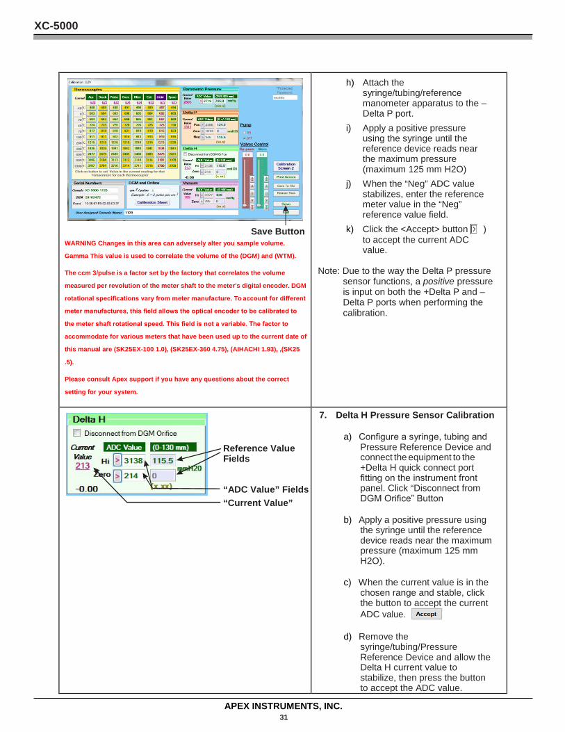
Reference Value Fields
“ADC Value” Fields “Current Value”
7. Delta H Pressure Sensor Calibration
a) Configure a syringe, tubing and Pressure Reference Device and connect the equipment to the +Delta H quick connect port fitting on the instrument front panel. Click “Disconnect from DGM Orifice” Button
b) Apply a positive pressure using the syringe until the reference device reads near the maximum pressure (maximum 125 mm H2O).
c) When the current value is in the chosen range and stable, click the button to accept the current ADC value.
d) Remove the syringe/tubing/Pressure Reference Device and allow the Delta H current value to stabilize, then press the button to accept the ADC value.
XC-5000
APEX INSTRUMENTS, INC. 32
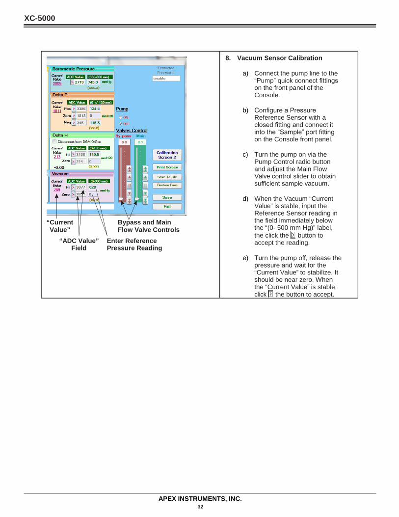
“Current Bypass and Main Value” Flow Valve Controls
“ADC Value” Enter Reference Field Pressure Reading
8. Vacuum Sensor Calibration
a) Connect the pump line to the “Pump” quick connect fittings on the front panel of the Console.
b) Configure a Pressure Reference Sensor with a closed fitting and connect it into the “Sample” port fitting on the Console front panel.
c) Turn the pump on via the Pump Control radio button and adjust the Main Flow Valve control slider to obtain sufficient sample vacuum.
d) When the Vacuum “Current Value” is stable, input the Reference Sensor reading in the field immediately below the “(0- 500 mm Hg)” label, the click the button to accept the reading.
e) Turn the pump off, release the pressure and wait for the “Current Value” to stabilize. It should be near zero. When the “Current Value” is stable, click the button to accept.
XC-5000
APEX INSTRUMENTS, INC. 33
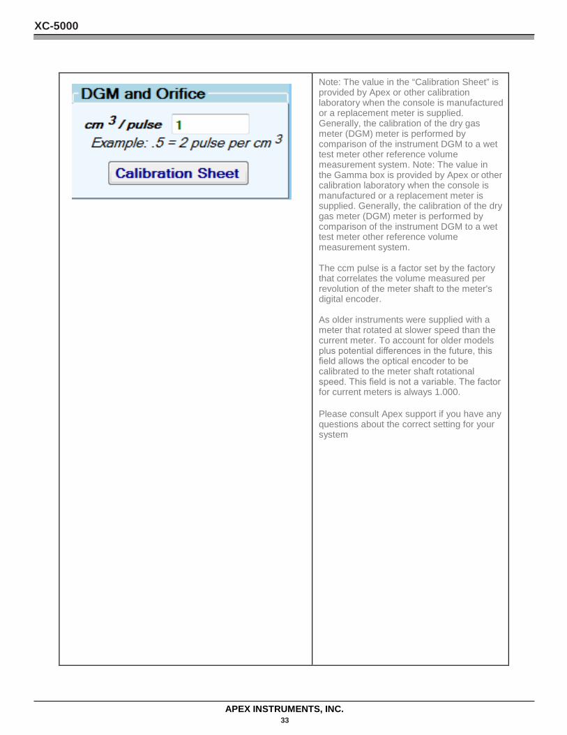
Note: The value in the “Calibration Sheet” is provided by Apex or other calibration laboratory when the console is manufactured or a replacement meter is supplied. Generally, the calibration of the dry gas meter (DGM) meter is performed by comparison of the instrument DGM to a wet test meter other reference volume measurement system. Note: The value in the Gamma box is provided by Apex or other calibration laboratory when the console is manufactured or a replacement meter is supplied. Generally, the calibration of the dry gas meter (DGM) meter is performed by comparison of the instrument DGM to a wet test meter other reference volume measurement system.
The ccm pulse is a factor set by the factory that correlates the volume measured per revolution of the meter shaft to the meter's digital encoder.
As older instruments were supplied with a meter that rotated at slower speed than the current meter. To account for older models plus potential differences in the future, this field allows the optical encoder to be calibrated to the meter shaft rotational speed. This field is not a variable. The factor for current meters is always 1.000.
Please consult Apex support if you have any questions about the correct setting for your system
XC-5000
APEX INSTRUMENTS, INC. 34
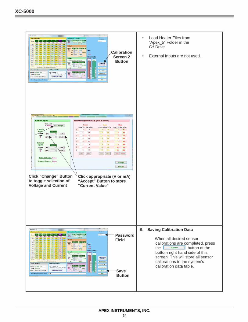
Calibration Screen 2 Button
Click “Change” Button Click appropriate (V or mA) to toggle selection of “Accept” Button to store Voltage and Current “Current Value”
• Load Heater Files from “Apex_5” Folder in the C:\ Drive.
• External Inputs are not used.
Password Field
Save Button
9. Saving Calibration Data
When all desired sensor calibrations are completed, press the button at the bottom right hand side of this screen. This will store all sensor calibrations to the system's calibration data table.
XC-5000
APEX INSTRUMENTS, INC. 35
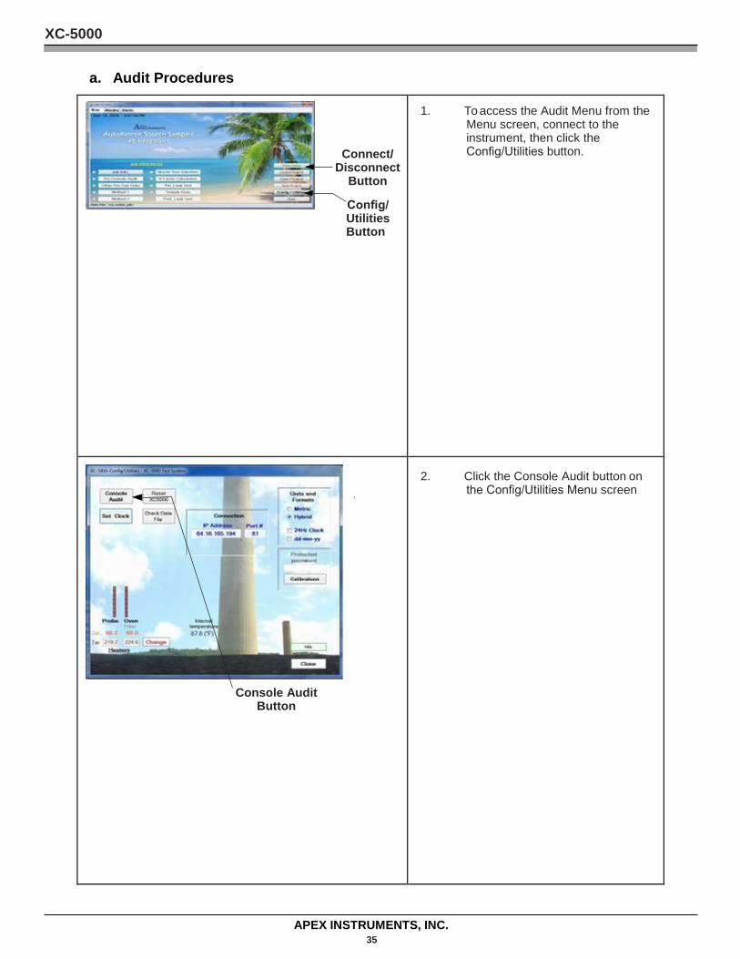
a. Audit Procedures
Connect/ Disconnect
Button
Config/ Utilities Button
1. To access the Audit Menu from the Menu screen, connect to the instrument, then click the Config/Utilities button.
Console Audit Button
2. Click the Console Audit button on the Config/Utilities Menu screen
XC-5000
APEX INSTRUMENTS, INC. 36
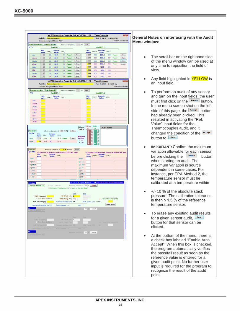
General Notes on interfacing with the Audit Menu window:
• The scroll bar on the righthand side of the menu window can be used at any time to reposition the field of view.
• Any field highlighted in YELLOW is an input field.
• To perform an audit of any sensor and turn on the input fields, the user must first click on the button. In the menu screen shot on the left side of this page, the button had already been clicked. This resulted in activating the “Ref. Value” input fields for the Thermocouples audit, and it changed the condition of the button to
• IMPORTANT: Confirm the maximum variation allowable for each sensor before clicking the button when starting an audit. The maximum variation is source dependent in some cases. For instance, per EPA Method 2, the temperature sensor must be calibrated at a temperature within
• +/- 10 % of the absolute stack pressure. The calibration tolerance is then ≤ 1.5 % of the reference temperature sensor.
• To erase any existing audit results for a given sensor audit, button for that sensor can be clicked.
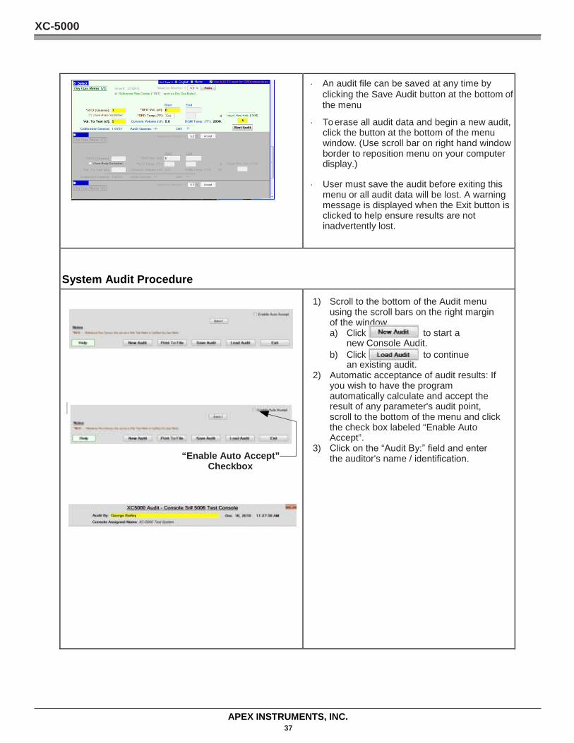
• At the bottom of the menu, there is a check box labeled “Enable Auto Accept”. When this box is checked, the program automatically verifies the pass/fail result as soon as the reference value is entered for a given audit point. No further user input is required for the program to recognize the result of the audit point.
XC-5000
APEX INSTRUMENTS, INC. 37
• An audit file can be saved at any time by clicking the Save Audit button at the bottom of the menu
• To erase all audit data and begin a new audit, click the button at the bottom of the menu window. (Use scroll bar on right hand window border to reposition menu on your computer display.)
• User must save the audit before exiting this menu or all audit data will be lost. A warning message is displayed when the Exit button is clicked to help ensure results are not inadvertently lost.
System Audit Procedure
“Enable Auto Accept” Checkbox
1) Scroll to the bottom of the Audit menu using the scroll bars on the right margin of the window. a) Click to start a
new Console Audit. b) Click to continue
an existing audit. 2) Automatic acceptance of audit results: If
you wish to have the program automatically calculate and accept the result of any parameter's audit point, scroll to the bottom of the menu and click the check box labeled “Enable Auto Accept”.
3) Click on the “Audit By:” field and enter the auditor's name / identification.
XC-5000
APEX INSTRUMENTS, INC. 38
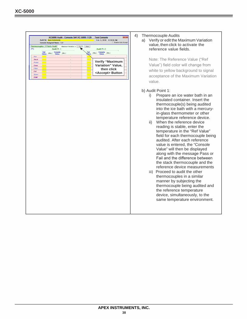
Verify “Maximum Variation” Value,
then click <Accept> Button
4) Thermocouple Audits a) Verify or edit the Maximum Variation
value, then click to activate the reference value fields.
Note: The Reference Value (“Ref Value”) field color will change from white to yellow background to signal acceptance of the Maximum Variation value.
b) Audit Point 1: i) Prepare an ice water bath in an
insulated container. Insert the thermocouple(s) being audited into the ice bath with a mercury- in-glass thermometer or other temperature reference device.
ii) When the reference device reading is stable, enter the temperature in the “Ref Value” field for each thermocouple being audited. After each reference value is entered, the “Console Value” will then be displayed along with the message Pass or Fail and the difference between the stack thermocouple and the reference device measurements
iii) Proceed to audit the other thermocouples in a similar manner by subjecting the thermocouple being audited and the reference temperature device, simultaneously, to the same temperature environment.
XC-5000
APEX INSTRUMENTS, INC. 39
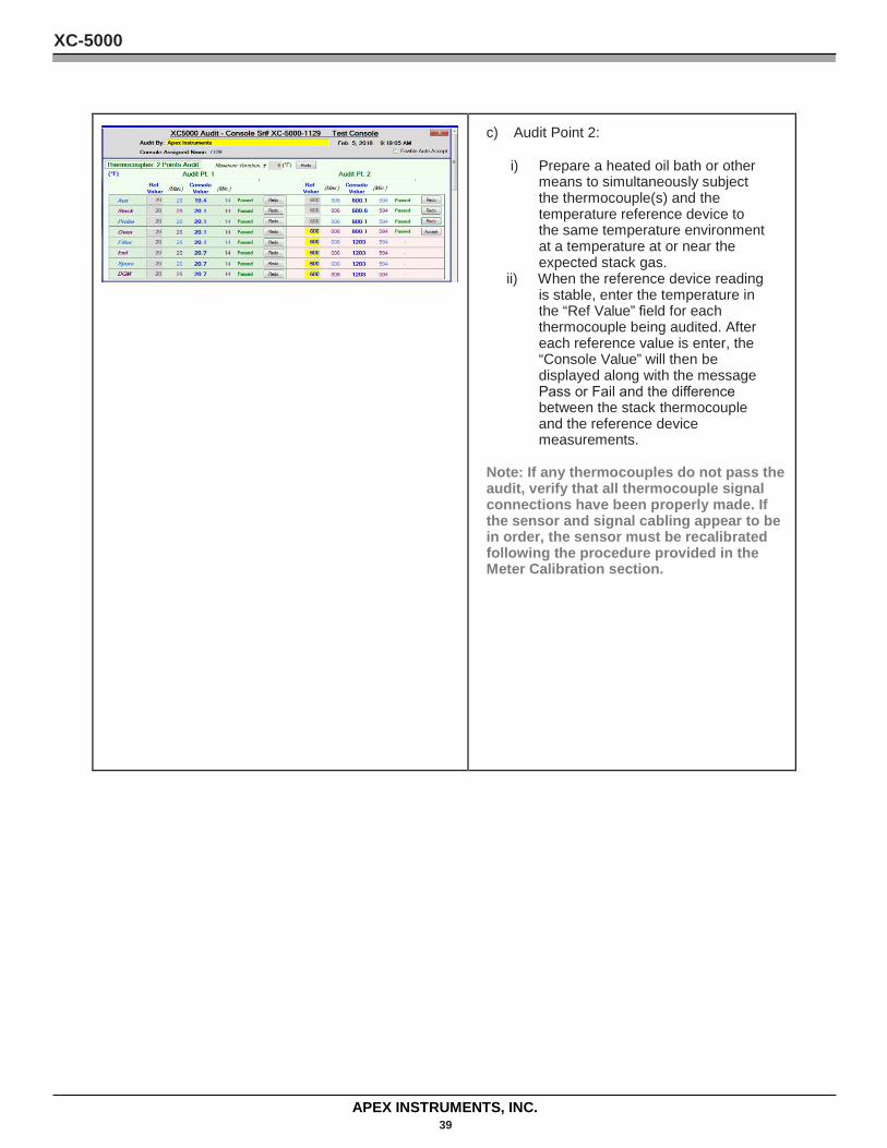
c) Audit Point 2: i) Prepare a heated oil bath or other
means to simultaneously subject the thermocouple(s) and the temperature reference device to the same temperature environment at a temperature at or near the expected stack gas.
ii) When the reference device reading is stable, enter the temperature in the “Ref Value” field for each thermocouple being audited. After each reference value is enter, the “Console Value” will then be displayed along with the message Pass or Fail and the difference between the stack thermocouple and the reference device measurements.
Note: If any thermocouples do not pass the audit, verify that all thermocouple signal connections have been properly made. If the sensor and signal cabling appear to be in order, the sensor must be recalibrated following the procedure provided in the Meter Calibration section.
XC-5000
APEX INSTRUMENTS, INC. 40
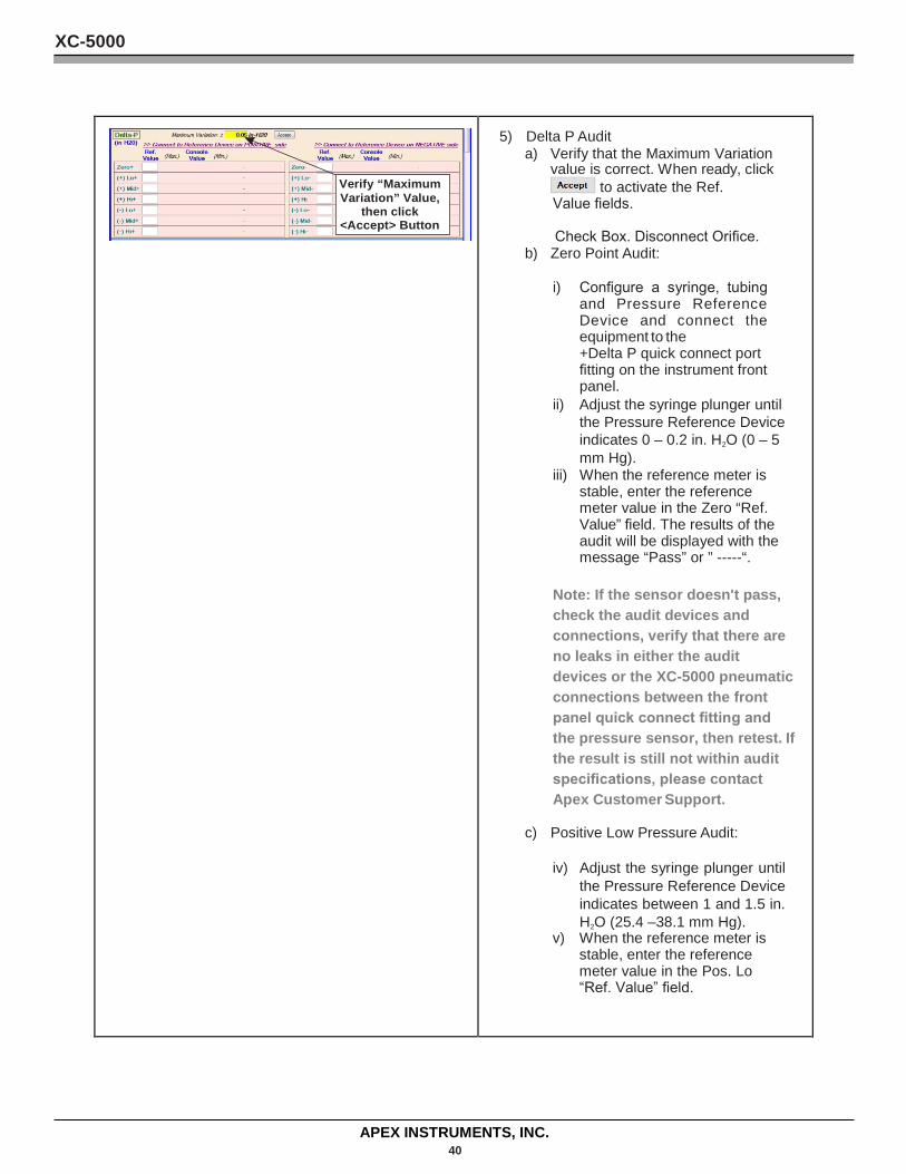
Verify “Maximum Variation” Value,
then click <Accept> Button
5) Delta P Audit a) Verify that the Maximum Variation
value is correct. When ready, click to activate the Ref.
Value fields.
Check Box. Disconnect Orifice. b) Zero Point Audit:
i) Configure a syringe, tubing and Pressure Reference Device and connect the equipment to the +Delta P quick connect port fitting on the instrument front panel.
ii) Adjust the syringe plunger until the Pressure Reference Device indicates 0 – 0.2 in. H2O (0 – 5 mm Hg).
iii) When the reference meter is stable, enter the reference meter value in the Zero “Ref. Value” field. The results of the audit will be displayed with the message “Pass” or ” -----“.
Note: If the sensor doesn't pass, check the audit devices and connections, verify that there are no leaks in either the audit devices or the XC-5000 pneumatic connections between the front panel quick connect fitting and the pressure sensor, then retest. If the result is still not within audit specifications, please contact Apex Customer Support.
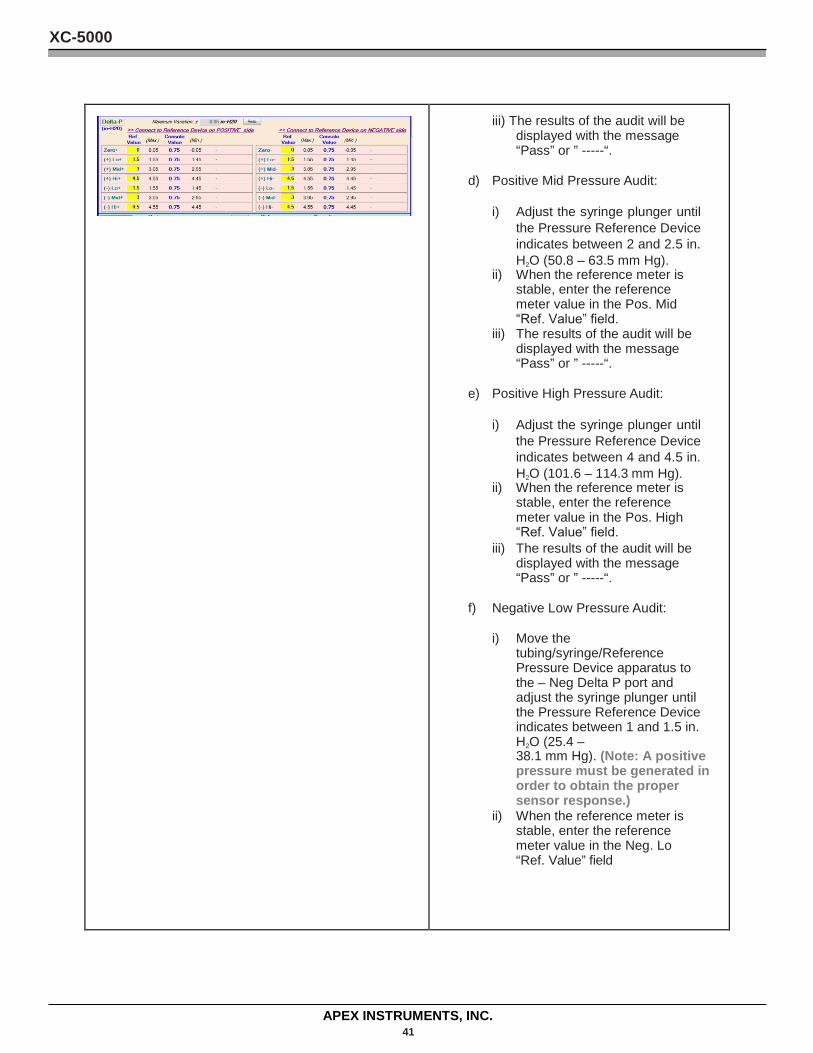
c) Positive Low Pressure Audit:
iv) Adjust the syringe plunger until the Pressure Reference Device indicates between 1 and 1.5 in. H2O (25.4 –38.1 mm Hg).
v) When the reference meter is stable, enter the reference meter value in the Pos. Lo “Ref. Value” field.
XC-5000
APEX INSTRUMENTS, INC. 41
iii) The results of the audit will be displayed with the message “Pass” or ” -----“.
d) Positive Mid Pressure Audit:
i) Adjust the syringe plunger until the Pressure Reference Device indicates between 2 and 2.5 in. H2O (50.8 – 63.5 mm Hg).
ii) When the reference meter is stable, enter the reference meter value in the Pos. Mid “Ref. Value” field.
iii) The results of the audit will be displayed with the message “Pass” or ” -----“.
e) Positive High Pressure Audit:
i) Adjust the syringe plunger until the Pressure Reference Device indicates between 4 and 4.5 in. H2O (101.6 – 114.3 mm Hg).
ii) When the reference meter is stable, enter the reference meter value in the Pos. High “Ref. Value” field.
iii) The results of the audit will be displayed with the message “Pass” or ” -----“.
f) Negative Low Pressure Audit:
i) Move the tubing/syringe/Reference Pressure Device apparatus to the – Neg Delta P port and adjust the syringe plunger until the Pressure Reference Device indicates between 1 and 1.5 in. H2O (25.4 – 38.1 mm Hg). (Note: A positive pressure must be generated in order to obtain the proper sensor response.)
ii) When the reference meter is stable, enter the reference meter value in the Neg. Lo “Ref. Value” field
XC-5000
APEX INSTRUMENTS, INC. 42
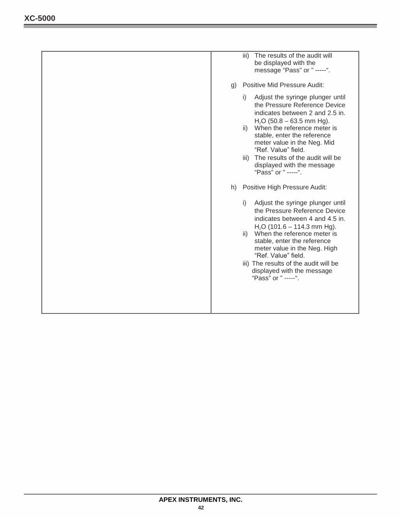
iii) The results of the audit will be displayed with the message “Pass” or ” -----“.
g) Positive Mid Pressure Audit:
i) Adjust the syringe plunger until the Pressure Reference Device indicates between 2 and 2.5 in. H2O (50.8 – 63.5 mm Hg).
ii) When the reference meter is stable, enter the reference meter value in the Neg. Mid “Ref. Value” field.
iii) The results of the audit will be displayed with the message “Pass” or ” -----“.
h) Positive High Pressure Audit:
i) Adjust the syringe plunger until the Pressure Reference Device indicates between 4 and 4.5 in. H2O (101.6 – 114.3 mm Hg).
ii) When the reference meter is stable, enter the reference meter value in the Neg. High “Ref. Value” field.
iii) The results of the audit will be displayed with the message “Pass” or ” -----“.
XC-5000
APEX INSTRUMENTS, INC. 43
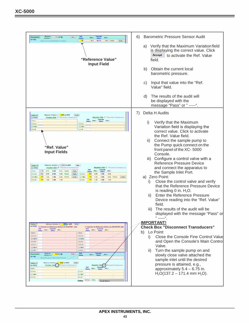
“Reference Value”
Input Field
6) Barometric Pressure Sensor Audit a) Verify that the Maximum Variation field
is displaying the correct value. Click to activate the Ref. Value
field.
b) Obtain the current local barometric pressure.
c) Input that value into the “Ref. Value” field.
d) The results of the audit will be displayed with the message “Pass” or ” -----“.
“Ref. Value” Input Fields
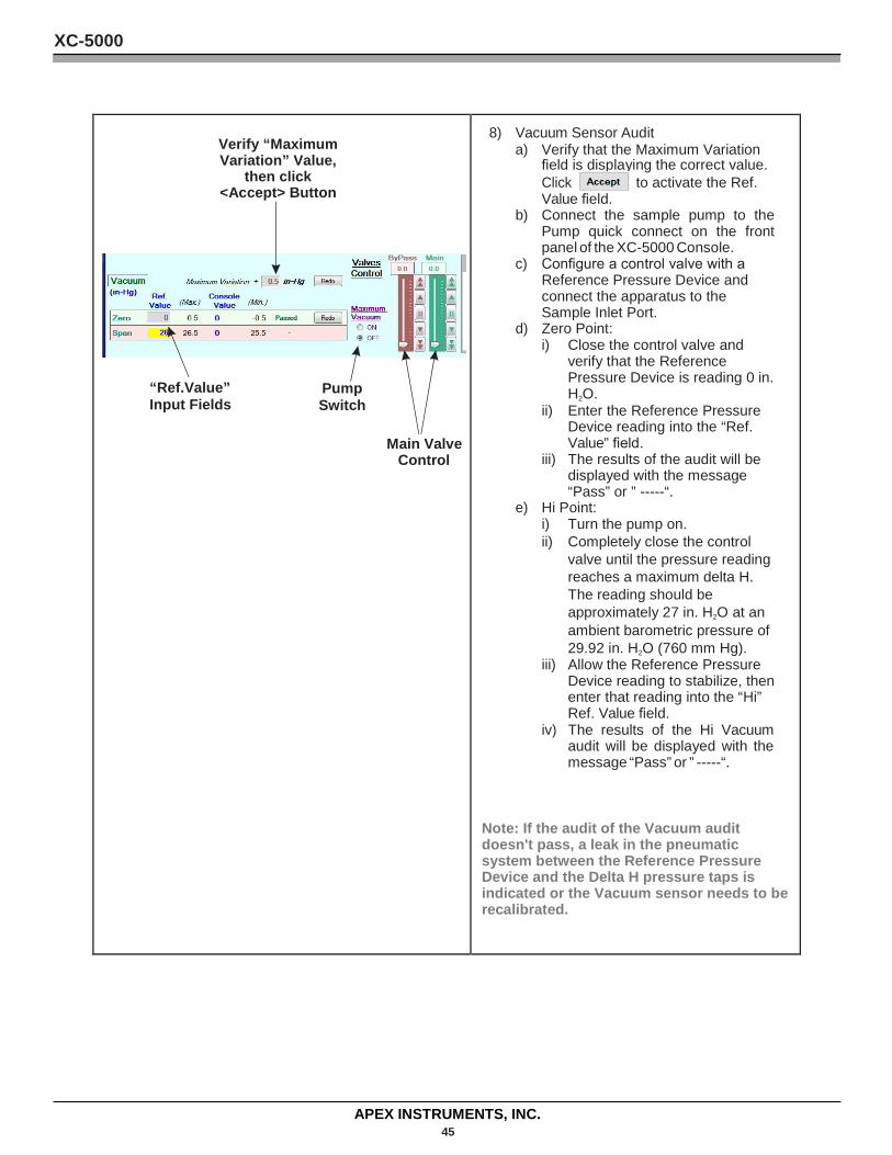
7) Delta H Audits
i) Verify that the Maximum Variation field is displaying the correct value. Click to activate the Ref. Value field.
ii) Connect the sample pump to the Pump quick connect on the front panel of the XC- 5000 Console.
iii) Configure a control valve with a Reference Pressure Device and connect the apparatus to the Sample Inlet Port.
a) Zero Point: i) Close the control valve and verify
that the Reference Pressure Device is reading 0 in. H2O.
ii) Enter the Reference Pressure Device reading into the “Ref. Value” field.
iii) The results of the audit will be displayed with the message “Pass” or ” -----“.
IMPORTANT! Check Box ”Disconnect Transducers” b) Lo Point:
i) Close the Console Fine Control Value and Open the Console's Main Control Valve.
ii) Turn the sample pump on and slowly close valve attached the sample inlet until the desired pressure is attained, e.g., approximately 5.4 – 6.75 in. H2O(137.2 – 171.4 mm H2O).
XC-5000
APEX INSTRUMENTS, INC. 44
iii) Allow the Reference
Pressure Device reading to stabilize, then enter that reading into the “Lo” Ref. Value field.
iv) The results of the Lo Delta H audit will be displayed with the message “Pass” or ” -----“.
Note: If the audit of the Lo point or any subsequent Delta H test point does not pass, a leak in the pneumatic system between the Reference Pressure Device and the Delta H pressure taps is indicated or the Delta H sensor needs to be recalibrated.
f) Mid Point: i) Close the control valve until
the pressure reading is between 10.8 and 13.5 in. H2O.
ii) Allow the Reference Pressure Device reading to stabilize, then enter that reading into the “Lo” Ref. Value field.
iii) The results of the Mid Delta H audit will be displayed with the message “Pass” or ” -----“.
g) Hi Point: i) Close the control valve until
the pressure reading is between 21.6 and 24.3 in. H2O.
ii) Allow the Reference Pressure Device reading to stabilize, then enter that reading into the “Lo” Ref. Value field. The results of the Hi Delta H audit will be displayed with the message “Pass” or ” -----“.
XC-5000
APEX INSTRUMENTS, INC. 45
Verify “Maximum Variation” Value,
then click <Accept> Button
“Ref.Value” Pump Input Fields Switch
Main Valve
Control
8) Vacuum Sensor Audit a) Verify that the Maximum Variation
field is displaying the correct value. Click to activate the Ref. Value field.
b) Connect the sample pump to the Pump quick connect on the front panel of the XC-5000 Console.
c) Configure a control valve with a Reference Pressure Device and connect the apparatus to the Sample Inlet Port.
d) Zero Point: i) Close the control valve and
verify that the Reference Pressure Device is reading 0 in. H2O.
ii) Enter the Reference Pressure Device reading into the “Ref. Value” field.
iii) The results of the audit will be displayed with the message “Pass” or ” -----“.
e) Hi Point: i) Turn the pump on. ii) Completely close the control
valve until the pressure reading reaches a maximum delta H. The reading should be approximately 27 in. H2O at an ambient barometric pressure of 29.92 in. H2O (760 mm Hg).
iii) Allow the Reference Pressure Device reading to stabilize, then enter that reading into the “Hi” Ref. Value field.
iv) The results of the Hi Vacuum audit will be displayed with the message “Pass” or ” -----“.
Note: If the audit of the Vacuum audit doesn't pass, a leak in the pneumatic system between the Reference Pressure Device and the Delta H pressure taps is indicated or the Vacuum sensor needs to be recalibrated.
XC-5000
APEX INSTRUMENTS, INC. 46
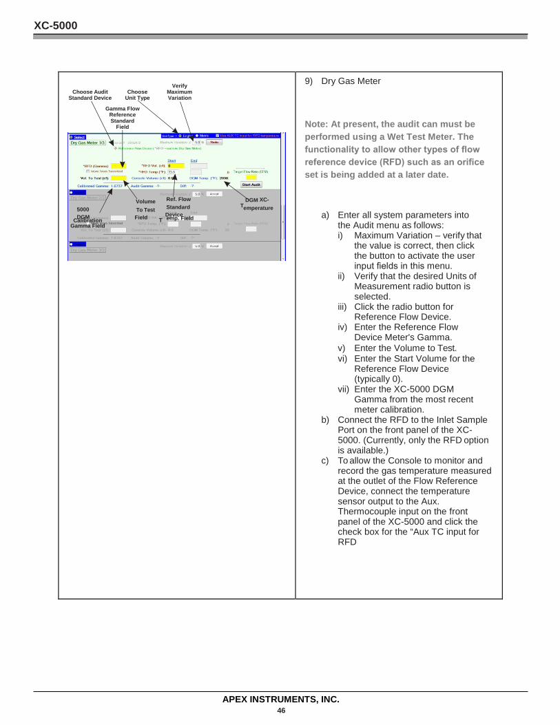
Verify
Choose Audit Choose Maximum Standard Device Unit Type Variation
Gamma Flow Reference Standard
Field
Volume Ref. Flow T
DGM XC-5000 To Test Standard emperature DGM Field T
Device Calibration emp. Field Gamma Field
9) Dry Gas Meter
Note: At present, the audit can must be performed using a Wet Test Meter. The functionality to allow other types of flow reference device (RFD) such as an orifice set is being added at a later date.
a) Enter all system parameters into the Audit menu as follows: i) Maximum Variation – verify that
the value is correct, then click the button to activate the user input fields in this menu.
ii) Verify that the desired Units of Measurement radio button is selected.
iii) Click the radio button for Reference Flow Device.
iv) Enter the Reference Flow Device Meter's Gamma.
v) Enter the Volume to Test. vi) Enter the Start Volume for the
Reference Flow Device (typically 0).
vii) Enter the XC-5000 DGM Gamma from the most recent meter calibration.
b) Connect the RFD to the Inlet Sample Port on the front panel of the XC- 5000. (Currently, only the RFD option is available.)
c) To allow the Console to monitor and record the gas temperature measured at the outlet of the Flow Reference Device, connect the temperature sensor output to the Aux. Thermocouple input on the front panel of the XC-5000 and click the check box for the “Aux TC input for RFD
XC-5000
APEX INSTRUMENTS, INC. 47
.
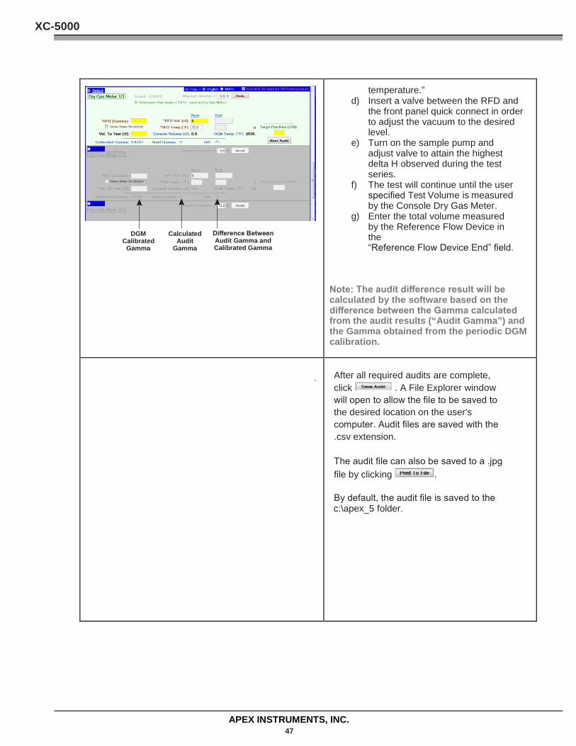
DGM Calculated Difference Between
Calibrated Audit Audit Gamma and Gamma Gamma Calibrated Gamma
temperature.” d) Insert a valve between the RFD and
the front panel quick connect in order to adjust the vacuum to the desired level.
e) Turn on the sample pump and adjust valve to attain the highest delta H observed during the test series.
f) The test will continue until the user specified Test Volume is measured by the Console Dry Gas Meter.
g) Enter the total volume measured by the Reference Flow Device in the “Reference Flow Device End” field.
Note: The audit difference result will be calculated by the software based on the difference between the Gamma calculated from the audit results (“Audit Gamma”) and the Gamma obtained from the periodic DGM calibration.
After all required audits are complete, click . A File Explorer window will open to allow the file to be saved to the desired location on the user's computer. Audit files are saved with the .csv extension. The audit file can also be saved to a .jpg file by clicking .
By default, the audit file is saved to the c:\apex_5 folder.